ICOM orporated IC-M402 Non-Brodcast Marine Transceiver User Manual IC M402 R s
ICOM Incorporated Non-Brodcast Marine Transceiver IC M402 R s
UserManual.wiki
>
ICOM orporated
>
IC-M402 User Manual
>
Manual
Contents
1.
Manual
2.
Revised Manual 2
Manual
Navigation menu
Upload a User Manual
Namespaces
Wiki Guide
HTML
PDF
Info
Views
User Manual
Discussion / Help
Navigation
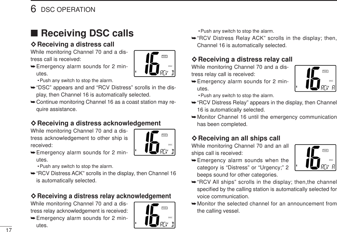
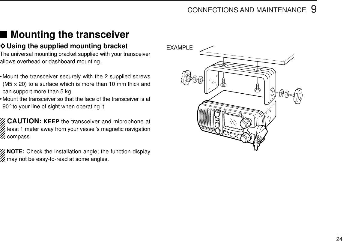
![IN CASE OF EMERGENCYiiIf your vessel requires assistance, contact other vessels andthe Coast Guard by sending a distress call on Channel 16.Or, transmit your distress call using digital selective calling onChannel 70.USING DIGITAL SELECTIVE CALLING (Ch 70)DISTRESS CALL PROCEDURE1. While lifting up the switch cover, push andhold [DISTRESS] for 5 sec. until you hear 5short beeps change to one long beep.2. Wait for an acknowledgment from a coaststation.•Channel 16 is automatically selected.3. Push and hold [PTT], then transmit theappropriate information as at left.USING CHANNEL 16DISTRESS CALL PROCEDURE1. “MAYDAY MAYDAY MAYDAY.”2. “THIS IS ...............” (name of vessel)3. Your call sign or other indication of the vessel(AND 9-digit DSC ID if you have one).4. “LOCATED AT ...............” (your position)5. The kind of the distress and assistancerequired.6.Any other information which might facilitatethe rescue.](https://usermanual.wiki/ICOM-orporated/IC-M402.Manual/User-Guide-132805-Page-3.png)
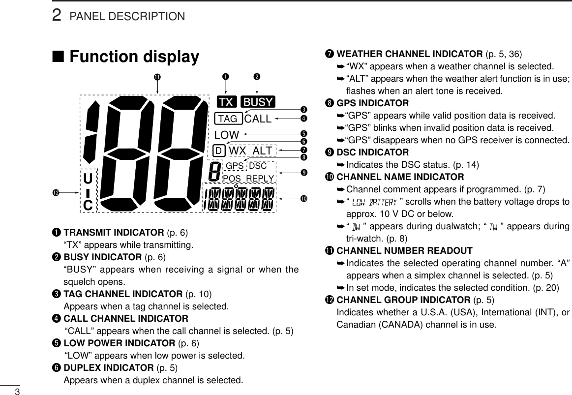
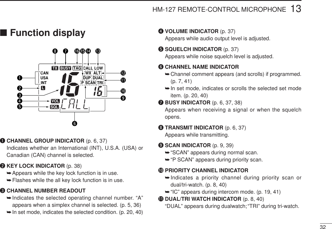
![22PANEL DESCRIPTION■Panel descriptionSpeaker Function display wuqertyiqCHANNEL UP / DOWN SWITCHES [YY] / [ZZ]➥Push to select the operating channels, set mode con-tents, etc. (p. 6)➥While pushing [H/L], push [Y] / [Z] to adjust the bright-ness of the LCD and switch backlight.➥Push for 1sec. to start/stop scanning(p. 9)➥Push [Y] and [Z] for 1sec. to toggle the tag setting forthe displayed channel. (p. 10)wPOWER / VOLUME CONTROL [VOL]Turns power ON and OFF and adjusts the audio level. (p. 6)eSQUELCH CONTROL [SQL]Sets the squelch threshold level. (p. 6)rTRANSMIT POWER SWITCH [H/L]➥Toggles high and low power when pushed. (p. 6)•Some channels are set to low power only.➥While pushing this switch, other switches perform sec-ondary functions.tCHANNEL SWITCH [CH/WX•DUAL]➥Selects and toggles the regular channels and weatherchannel when pushed momentarily. (p. 5)➥While pushing [HI/LO], selects one of 3 regular channelsin sequence when pushed. (p. 5)•International, U.S.A. and Canadian channels are available forregular channels.➥Starts dualwatch or tri-watch when pushed for 1 sec. (p. 8)➥Stops dualwatch or tri-watch when either is activated.yCHANNEL 16/CALL CHANNEL SWITCH [16•9]➥Selects channel 16 when pushed. (p. 5)➥Selects call channel when pushed for 1 sec. (p. 5)•“CALL” appears when call channel is selected.➥Push for 3 sec. to enter call channel programming con-dition when call channel is selected. (p. 7)➥While pushing [H/L], enters memory name programmingcondition. (p. 7)➥Enters set mode when pushed while turning power ON.(p. 20)uDISTRESS SWITCH [DISTRESS]Transmits distress call when pushed for 5 sec. (p. 17)iDSC/POSITION SWITCH [DSC/ENT•POS]➥Selects the DSC menu when pushed. (p. 11)➥Shows current position and time from an optional GPSreceiver, etc. when pushed for 1 sec. (p. 11)](https://usermanual.wiki/ICOM-orporated/IC-M402.Manual/User-Guide-132805-Page-7.png)
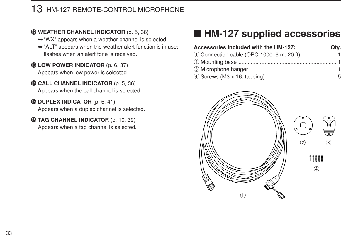
![PANEL DESCRIPTION42■MicrophoneqPTT SWITCH [PTT]Push and hold to transmit; release to receive. (p. 6)wCHANNEL UP/DOWN SWITCHES [YY]/[ZZ]Push either switch to change the operating memory chan-nel, set mode contents, etc. (p. 6)eCHANNEL 16/CALL CHANNEL SWITCH [16•9]➥Same as the [H/L] switch on the front panel. (p. 6)➥Selects channel 16 when pushed. (p. 5)➥Selects call channel when pushed for 1 sec. (p. 5)•“CALL” appears when call channel is selected.➥Push for 3 sec. to enter call channel programming con-dition when call channel is selected. (p. 7)➥While pushing [H/L], enters memory name programmingcondition. (p. 7)➥While pushing [16] on the supplied microphone, turnpower ON to toggle the lock function ON and OFF. (p. 6)Microphonewqe](https://usermanual.wiki/ICOM-orporated/IC-M402.Manual/User-Guide-132805-Page-9.png)
![■Channel selection◊Channel 16Channel 16 is the distress and safety channel. It is used forestablishing initial contact with another station and for emer-gency communications. Channel 16 is monitored during bothdualwatch and tri-watch. While standing by, you must monitorchannel 16.➥Push [16 ] momentarily to select channel 16.➥Push [CH/WX] to return to thecondition before selecting chan-nel 16, or push [Y] / [Z] to se-lect an operating channel.◊Channel 9 (Call channel)Each regular channel group has a separate leisure-use callchannel. The call channel is monitored during tri-watch. Thecall channels can be programmed (p. 7) and are used to storeyour most often used channels in each channel group forquick recall.➥Push [16] for 1 sec. to select the call channel of the se-lected channel group.•“CALLING” and call channel number appear. •Each channel group may have an independent call channel.➥Push [CH/WX] to return to thecondition before selecting callchannel,or push [Y] / [Z] toselect an operating channel.◊U.S.A., Canadian and international channelsThere are 57 U.S.A., 61 Canadian and 57 international chan-nels. These channel groups may be specified for the operat-ing area.qPush [CH/WX] to select a regular channel.•If a weather channel appears, push [CH/WX] again.wPush [CH/WX] while pushing [H/L] to change the channelgroup, if necessary.•U.S.A., International (INT) and Canadian channels can be se-lected in sequence.eRotate the channel selector to select a channel.•“D” appears for duplex channels.•“A” appears for simplex channels.53BASIC OPERATIONITAGPushICALLTAGPushPush +U.S.A. channelsCanadian channels International channelsCTAGIDTAGUTAG](https://usermanual.wiki/ICOM-orporated/IC-M402.Manual/User-Guide-132805-Page-10.png)
![◊Weather channelsThere are 10 weather channels. Used for monitoring weatherchannels from the NOAA (National Oceanographic and At-mospheric Administration) broadcasts.The transceiver can detect a weather alert tone on the se-lected weather channel while receiving the channel, duringstandby on a regular channel or while scanning. (p. 20) qPush [CH/WX] once or twice to select a weather channel.•“WEATHER” appears when aweather channel is selected.“WX ALT” appears when theweather alert function is in use.(p. 20)wRotate the channel selector toselect a channel.•Channels are memorized sepa-rately for each channel group■Microphone lock functionThe microphone lock function electrically locks the [Y]/[Z]and [16] switches on the supplied microphone. This preventsaccidental channel changes and accidental function access.➥While pushing [16] on the supplied microphone, turn powerON to toggle the lock function ON and OFF.3BASIC OPERATION6Push once or twiceWhen weather alert is OFF.When weather alert is ON.WXWX ALT■Receiving and transmittingCAUTION: Transmitting without an antenna may dam-age the transceiver.qTurn [VOL] right to turn power ON.wSet the audio and squelch levels.➥Rotate [SQL] fully counterclockwise in advance.➥Rotate [VOL] to adjust the audio output level.➥Rotate [SQL] clockwise until the noise disappears.ePush [Y]/[Z] to select the desired channel. (p. 5)•When receiving a signal, “BUSY” appears and audio is emittedfrom the speaker.rPush [H/L] to select the output power if necessary.•“LOW” appears when low power is selected.•Choose high power for longer distance communications.•Some channels are for low power only.tPush and hold [PTT] to transmit, then speak into the mi-crophone.•“TX” appears.•Channel 70 cannot be used for transmission (for GMDSS use).Simplex channels, 3, 21, 23, 61, 64, 81, 82 and 83 CAN-NOT be lawfully used by the general public in U.S.A. waters.yRelease [PTT] to receive.IMPORTANT: To maximize the readability of your trans-mitted signal, pause a few sec. after pushing [PTT], holdthe microphone 4 to 6 inches (10 to 15 cm) from yourmouth and speak at a normal voice level.](https://usermanual.wiki/ICOM-orporated/IC-M402.Manual/User-Guide-132805-Page-11.png)
![3BASIC OPERATION7■Call channel programmingThe call channel is used to select Channel 9, however, youcan program your most often-used channels in each channelgroup for quick recall.qWhile pushing [H/L], push [CH/WX] one or more times toselect the desired channel group (U.S.A., International,Canada) to be programmed.wPush [16 ] for 1 sec. to select the call channel of the se-lected channel group.•“CALL” and call channel number appear.ePush [16 ] again for 3 sec. (untillong beep changes to 2 shortbeeps) to enter call channel pro-gramming condition.•Channel number starts flashing.rPush [Y]/[Z] to select the de-sired channel.tPush [16 ] to program the dis-played channel as the call chan-nel.•Push [CH/WX] to cancel.•The channel number stops flashing.■Channel namesMemory channels can be tagged with alphanumeric namesof up to 10 characters each. Capital letters, small letters, numerals, some symbols (! " # $% & ' ( ) ✱+ ,– .⁄) and spaces can be used.qSelect the desired memory channel.•Cancel dual watch, tri-watch or scan in advance.wWhile pushing [H/L], push [16 ] to edit memory channelname.•A cursor appears and blinks.eSelect the desired character by pushing [Y]/[Z].•Push [CH/WX] or [H/L] for cursor movement.rPush [16 ] to input and set the name.•Push [H/L] to cancel.•The cursor disappears.tRepeat steps qto rto program other memory channelnames, if desired.ICALLTAGIDCALLTAGITAG](https://usermanual.wiki/ICOM-orporated/IC-M402.Manual/User-Guide-132805-Page-12.png)
![84DUAL WATCH/TRI-WATCH■DescriptionDualwatch monitors channel 16 while you are receiving an-other channel; tri-watch monitors Channel 16 and the callchannel while receiving another channel.DUALWATCH/TRI-WATCH SIMULATION•If a signal is received on Channel 16, dualwatch/tri-watch pauseson Channel 16 until the signal disappears.•If a signal is received on the call channel during tri-watch, tri-watchbecomes dualwatch until the signal disappears.•To transmit on the selected channel during dualwatch/tri-watch, pushand hold [PTT].■OperationqSelect the desired operating channel.wSelect dualwatch or tri-watch in set mode. (p. 20)ePush [CH/WX] for 1 sec. to start dualwatch or tri-watch.•“ ” appears during dualwatch; “ ” appears during tri-watch.•Beep tone sounds when a signal is received on Channel 16.rTo cancel dualwatch/tri-watch, push [CH/WX] again.Dualwatch Tri-watchCall channelOperating tri-watch on INTchannel 25Operating dual-watch on INTchannel 25Dual-watch starts.IDTAGSignal received on channel 16 takes priority.IDBUSYBUSYTAGDual-watch resumes after the signal disappears.IDTAGTri-watch starts.Signal is received on call channel.Signal received on channel 16 takes priority.Tri-watch resumes after the signal disappears.IDTAGIDBUSYBUSYTAGICALLBUSYBUSYTAGIDTAG[Example]](https://usermanual.wiki/ICOM-orporated/IC-M402.Manual/User-Guide-132805-Page-13.png)
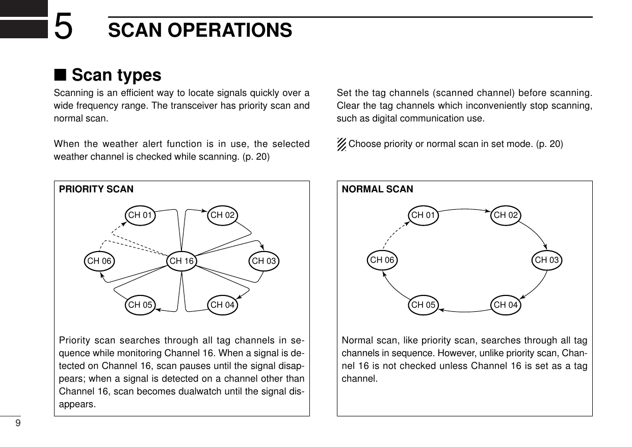
![105SCAN OPERATIONScan starts. When a signal is receiveIDTAGIDTAGIDBUSYBUSYTAG[Example]: Starting a priority scan.■Setting tag channelsFor more efficient scanning, add desired channels as tagchannels or clear tag channels for unwanted channels. Chan-nels set as non-tag channels will be skipped during scanning.Tag channels can be assigned to each channel group(U.S.A., International, Canada) independently.qWhile pushing [H/L], push [CH/WX] one or more times toselect the desired channel group, if desired.wSelect the desired channel to set as a tag channel.ePush [Y] and [Z] for 1 sec. to set the displayed channelas a tag channel.•“TAG” appears in the function display.rTo cancel the tag channel setting, repeat e.•“TAG” disappears.•Clearing all tag channels in the selected channel group➥While pushing [Y] and [Z], Turn power ON to clear all tagchannels in the channel group.■Starting a scanSet scan type (priority or normal scan) and scan resume timerin advance using set mode. (p. 20)qSet tag channels as described at left.wMake sure the squelch is closed to start a scan.eWhile pushing [H/L], push [CH/WX] one or more times toselect the desired channel group, if desired.rPush [Y] or [Z] for 1 sec. to start priority or normal scan.•“Pri scan 16” or “Normal scan” appears in the function display.•When a signal is detected, scan pauses until the signal disap-pears or resumes after pausing 5 sec. according to set mode set-ting. (Channel 16 is still monitored during priority scan.)•Rotate the channel selector to check the scanning tag channels,to change the scanning direction or resume the scan manually.•“16” flashes and a beep tone sounds when a signal is receivedon Channel 16 during priority scan.•Push [Y] and [Z] for 1 sec. to set the paused channel as a tagchannel.tTo stop the scan, push [Y] or [Z].Push [Y] or [Z] for 1 sec.](https://usermanual.wiki/ICOM-orporated/IC-M402.Manual/User-Guide-132805-Page-15.png)
![■MMSI code programmingThe 9-digit MMSI (DSC self ID) code can be programmed atpower ON.This function is not available when the MMSI code hasbeen programmed by the dealer. This code programmingcan be performed only 2 times.qTurn power OFF.wWhile pushing [DSC], turn power ON to enter MMSI codeprogramming condition.eAfter the display appears, release [DSC].rSelect the desired number by pushing [Y]/[Z] . tPush [CH/WX] to advance the cursor.•Push [H/L] to move the cursor backward.yRepeat steps rand tto input 9 digitcode.uPush [DSC] to input and set the code.•The previously selected channel appears.■MMSI code checkThe 9-digit MMSI (DSC self ID) code can be checked.qPush [DSC] to select the DSC menu.wPush [Y]/[Z] to select “MMSI” andpush [DSC].eCheck the 9-digit MMSI (DSC self ID)code.rPush [DSC] to exit the condition.■Position indicationWhen an optional GPS receiver (NMEA0183 ver. 2.0) is con-nected, the transceiver can display the current position and time. A GPS receiver appropriate for the IC-M402 is not supplied fromIcom. An NMEA0183 ver. 2.0 is required for position indication.Ask your dealer about the GPS receiver.➥While pushing [H/L], push [DSC] for 1 sec. to display the cur-rent position.•“Latitude and longitude are displayed alternately.ITAGGPSITAGGPS116DSC OPERATIONIDTAGIDTAG](https://usermanual.wiki/ICOM-orporated/IC-M402.Manual/User-Guide-132805-Page-16.png)
![126DSC OPERATION■Distress callA distress call should be transmitted if, in the opinion of theMaster, the ship or a person is in distress and requires imme-diate assistance.NEVER USE THE DISTRESS CALL WHENYOUR SHIP IS NOT IN AN EMERGENCY. ADISTRESS CALL CAN BE USED ONLY WHENIMMEDIATE HELP IS NEEDED.qConfirm any distress call is not being received.wWhile lifting up the switch cover, pushthe [DISTRESS] switch for 5 sec. totransmit the distress call.•An emergency channel (Ch 70) is auto-matically selected and the distress call is transmitted..eAfter transmitting the call, the transceiver waits for an ac-knowledgment call on Ch70.•The distress call is automatically transmit-ted every 3.5 to 4.5 minutes.•”DSC RPEAT” scrolls.rWhen receiving the acknowledgment,reply to the connected station via themicrophone.•”RCV Distress ACK” scrolls.➥Distress alert contains (default);•Kinds of distress : Undesignated distress•Position data : Latest GPS position data held for 23.5 hrs.or until the power is turned OFF.➥The distress call is repeated every 3.5–4.5 min., until re-ceiving an ‘acknowledgement.’➥Push [DISTRESS] to transmit a renewed distress call, ifdesired.➥Push [16] to cancel the ‘Call repeat’ mode.ITXTXILOWIDSC](https://usermanual.wiki/ICOM-orporated/IC-M402.Manual/User-Guide-132805-Page-17.png)
![13■Transmitting DSC calls◊Transmitting individual callThe individual call function allows you to transmit a DSC sig-nal to a specific party only.qSelect a desired channel other thanChannel 70.wPush [DSC] to select the DSC menuePush [Y]/[Z] to select “individual” andpush [DSC].rPush [Y]/[Z] to select the desired pre-programmed individual address.•The ID code for the individual call can beset in advance. (p. 22)tPush [DSC] to enter pre-programmed individual address.•‘OK’ appears.yPush [DSC] to transmit the individual call.•Channel 70 is selected and the individual call is transmitted tothe selected station.•If Channel 70 is busy, the transceiver stands by until the channelbecomes clear.•Routine category only is available.Push [DSC] to transmit DSC CALL. When Ch 70 is busy.uStan dby on Channel 70 until an ac-knowledgement is received.•”WAITING ACK” scrolls.iWhen the acknowledgement is re-ceived, the display changes to the previously selected userchannel with beeps.oPush and hold [PTT] to communicate your message to theresponding party.IBUSYBUSYILOWD6DSC OPERATIONILOWDILOWDTAGILOW](https://usermanual.wiki/ICOM-orporated/IC-M402.Manual/User-Guide-132805-Page-18.png)
![146DSC OPERATION◊Transmitting individual acknowledgementTransmit an acknowledgement (‘able to comply’ or ‘unable tocomply’) when an individual call for you is received.q“RCV Individual” scrolls.wPush [Y] or [Z] to select the acknowledgement “ABLE” or“UNABLE”.ePush [DSC] to enter selected individ-ual call acknowledgement, “OK” ap-pears.rPush [DSC] to.transmit individual callacknowledgementtIf you select “Able”,the channel speci-fied by the calling stationl is automati-cally selected.◊Transmitting all ships callLarge ships use Channel 70 as their “listening channel.”When you want to announce a message to these ships, usethe “all ships call” function.qSelect a desired channel other than Channel 70.wPush [DSC] to select the DSC menuePush [Y]/[Z] to select “ALL SHIPS”.•Routine category only is available.rPush [DSC] to enter all ships call.•‘OK’ appears.tPush [DSC] to transmit the all shipscall.•Channel 70 is selected and the all shipscall is transmitted.•Routine category only is available.yThe all ships call has been transmit-ted.•A previous channel is selected automati-cally.uPush [PTT] or [Y]/[Z] to exit the condition.ITAGDSCITXTXTAGITAGITAGDSCITAGDSCIDTAGIDTAGILOWTXTXTAGIDTAG](https://usermanual.wiki/ICOM-orporated/IC-M402.Manual/User-Guide-132805-Page-19.png)
![15◊Transmitting position request callTransmit a position request call when you want to know yourfriend’s current position, etc.qSelect a desired channel other than Channel 70.wPush [DSC] to select the DSC menuePush [Y]/[Z] to select “POS RE-QUEST”.rPush [Y]/[Z] to select the desired pre-programmed individual address.•The ID code for position request can beset in advance. (p. 22)tPush [DSC] to enter pre-programmed individual address.•“OK” appears.yPush [DSC] to transmit the positionrequest call.•Channel 70 is selected and the positionrequest call is transmitted.uThe position request call has beentransmitted.•”WAITING ACK” scrolls.iPush [PTT] or rotate the channel selector to exit the condi-tion.◊Transmitting position reply callTransmit a position reply call when a position request call isreceived.q”DSC” appears and a“RCV Pos re-quest” scrolls in the display.wPush [DSC] to reply to the position request call; push [H/L]to ignore the position request call.6DSC OPERATIONIDTAGILOWDTAGITXTXTAGILOWTAGIDTAGDSC](https://usermanual.wiki/ICOM-orporated/IC-M402.Manual/User-Guide-132805-Page-20.png)
![166DSC OPERATION■DSC individual IDA total of 40 DSC address ID’s can be programmed andnamed with up to 10 characters.◊Programming address IDqPush [DSC] to select the DSC menu.wPush [Y]/[Z] to select “ADDRESS”and push [DSC].ePush [Y]/[Z] to select “ADD” andpush [DSC].rSet the distress ID and ID name, thenpush [DSC/ENT].• Rotate the channel selector to select thecharacter.•Push [H/L] to advance the cursor.•Push [CH/WX] to move the cursor back-ward.•Push [16] to cancel and exit the condition.•Up to 5 characters available to enter IDnames.tPush [DSC] to program and to exit the condition.◊Deleting address IDqPush [DSC] to select the DSC menu.wPush [Y]/[Z] to select “ADDRESS” and push [DSC].ePush [Y]/[Z] to select ‘DEL,’ thenpush [DSC].•When no address ID is programmed, thetransceiver exits the condition automati-cally.rSelect the desired ID name pushing[Y]/[Z], then push [DSC].tPush [DSC] to delete the address ID;push an other switch to exit the condi-tion.IDTAGIDTAGIDTAGIDTAGIDTAGIDTAG](https://usermanual.wiki/ICOM-orporated/IC-M402.Manual/User-Guide-132805-Page-21.png)
![186DSC OPERATION◊Receiving an individual callWhile monitoring Channel 70 and an in-dividual call is received:➥Emergency alarm or beeps sound de-pending on the received category.➥“RCV Individual” scrolls in the display, then the channelspecified by the calling station is automatically selected forchecking the channel condition.◊Receiving a geographical area callWhile monitoring Channel 70 and a geo-graphical area call (for the area you arein) is received:➥Emergency alarm or beeps sound de-pending on the received category.➥“RCV Geographic” scrolls, then the channel specified bythe calling station is automatically selected for voice com-munications.➥Monitor the selected channel for an announcement fromthe calling ship.When no GPS receiver is connected or if there is a prob-lem with the connected receiver, all geographical area callsare received, regardless of your position.◊Receiving a position reply callWhile monitoring Channel 70 and a position reply call (for thearea you are in) is received:➥“Received POS” appears in the display.•“Latitude and longitude are displayed alternately.When no GPS receiver is connected or if there is a prob-lem with the connected receiver, all geographical area callsare received, regardless of your position.◊Receiving a position request callWhile monitoring Channel 70 and a posi-tion request call (for the area you are in)is received:➥“RCV Pos request” scrolls in the dis-play.➥Push [DSC] to reply to the call.When no GPS receiver is connected or if there is a prob-lem with the connected receiver, all geographical area callsare received, regardless of your position.ITAGITAGDSCPOS REPLY DSCPOS REPLYITAGDSCITAGDSCITAGDSC](https://usermanual.wiki/ICOM-orporated/IC-M402.Manual/User-Guide-132805-Page-23.png)
![197INTERCOM OPERATION■Intercom operationThe optional intercom function allows you to talk to the deckfrom the cabin. The optional HM-127 REMOTE-CONTROL MI-CROPHONE is required for intercom operation.Connect an optional HM-127 as described on p. 37.•Transmitting is impossible during intercom operation.•The received signal is muted during intercom operation.qPush [DSC] for 1 sec. to enter intercom mode.•The HM-127 power is automatically turned ON, even if the HM-127 power is OFF.wPush and hold [DSC] again to call up.•The transceiver and microphone emit call beeps.ePush and hold the PTT switch and speak at a normal voicelevel into the microphone.•“TALK” or “LSTN” appears on the caller or listener function dis-play, respectively.•To adjust the IC-M402’s speaker output level, rotate [VOL].•To adjust the HM-127’s speaker output level, push [Y]/[Z] afterpushing [VOL] on the HM-127.rAfter releasing the PTT switch you can hear the responsethrough the speaker.tTo return to normal operation, push [DSC] momentarily.•Other switches also turn the function OFF, however, the corre-sponding function is then activated e.g. pushing [16] selectsChannel 16.•While in the intercom mode, the transceiver functions(transmit and receive) are interrupted. If the transceiver isin transmit condition, the intercom function is not avail-able.•When a DSC call is received, “DSC received” appearsand the last received DSC message is displayed after theintercom use is finished.•When a WX alert is received, “WX ALT” flashes and abeep sounds. The WX alert sounds after the intercom useis finished.INTHM-127 (listener)IC-M402 (caller)ITAGINTHM-127IC-M402ITAG](https://usermanual.wiki/ICOM-orporated/IC-M402.Manual/User-Guide-132805-Page-24.png)
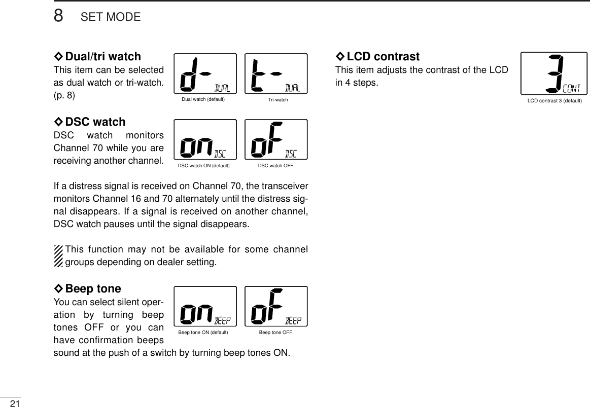
![208SET MODEScan mode Weather alertScan resume timer Dual/tri watchDSC watchLCD contrastWX ALTBeep tonePush■Set mode programmingSet mode is used to change the conditions of some of thetransceiver’s functions.•Available functions may differ depending on dealer setting.•The optional HM-127 has it’s own settings for the beeptone and LCD contrast.qTurn power OFF.wWhile pushing [16], turn power ON to enter set mode.eAfter the display appears, release [16].rPush [16] to select the desired item, if necessary.tPush [Y]/[Z] to select the desired condition of the item. yTurn power OFF, then ON again to exit set mode.•SET MODE CONSTRUCTION■Set mode items◊Scan modeThe scan mode can be se-lected as a normal scan orpriority scan. (p. 9)◊Scan resume timerThe scan resume timer canbe selected as a pause(OFF) or timer scan (ON).When OFF is selected, thescan pauses until the signaldisappears. When ON is selected, the scan pauses 5 sec. andresumes even if a signal is being received on channels exceptfor Channel 16.◊Weather alertAn NOAA broadcast sta-tion transmits a weatheralert tone before importantweather information. Whenthe weather alert function is turned ON, the transceiver detectsthe alert, then flashes the “WX ALT” indicator until the trans-ceiver is operated. The previously selected (used) weatherchannel is checked any time during standby or while scanning.•“ALT” appears with “WX” indication when the function is set ON.Normal scan (default) Priority scanScan timer OFF (default) Scan timer ONWeather alert ONWX ALTWeather alert OFF (default)WX](https://usermanual.wiki/ICOM-orporated/IC-M402.Manual/User-Guide-132805-Page-25.png)
![PROBLEM REF.POSSIBLE CAUSE SOLUTIONNo power comes ON.No sound comes fromthe speaker.Scan does not start.Transmitting is impossi-ble, or high power can-not be selected.No beep sounds.Distress call cannot betransmitted.•Squelch level is too deep.•Volume level is too low.•Speaker has been exposed to water.•Bad connection to the power supply.•Some channels are for low power orreceive only.•The output power is set to low.•TAG channel is not programmed.•Beep tone is turnd OFF.•The squelch is open.•MMSI (DSC self ID) code is not pro-grammed.•Check the connection to the transceiver.•Set squelch to the threshhold point.•Set [VOL] to a suitable level.•Drain water from the speaker.•Change channels.•Push [H/L] to select high power.•Set the desired channels as TAG channels.•Turn the beep tone ON in set mode.•Set squelch to the threshold point.•Program the MMSI (DSC self ID) code.p. 22p. 6p. 6p. 5,27p. 6p. 10p. 21p. 6p. 112610TROUBLESHOOTING](https://usermanual.wiki/ICOM-orporated/IC-M402.Manual/User-Guide-132805-Page-31.png)
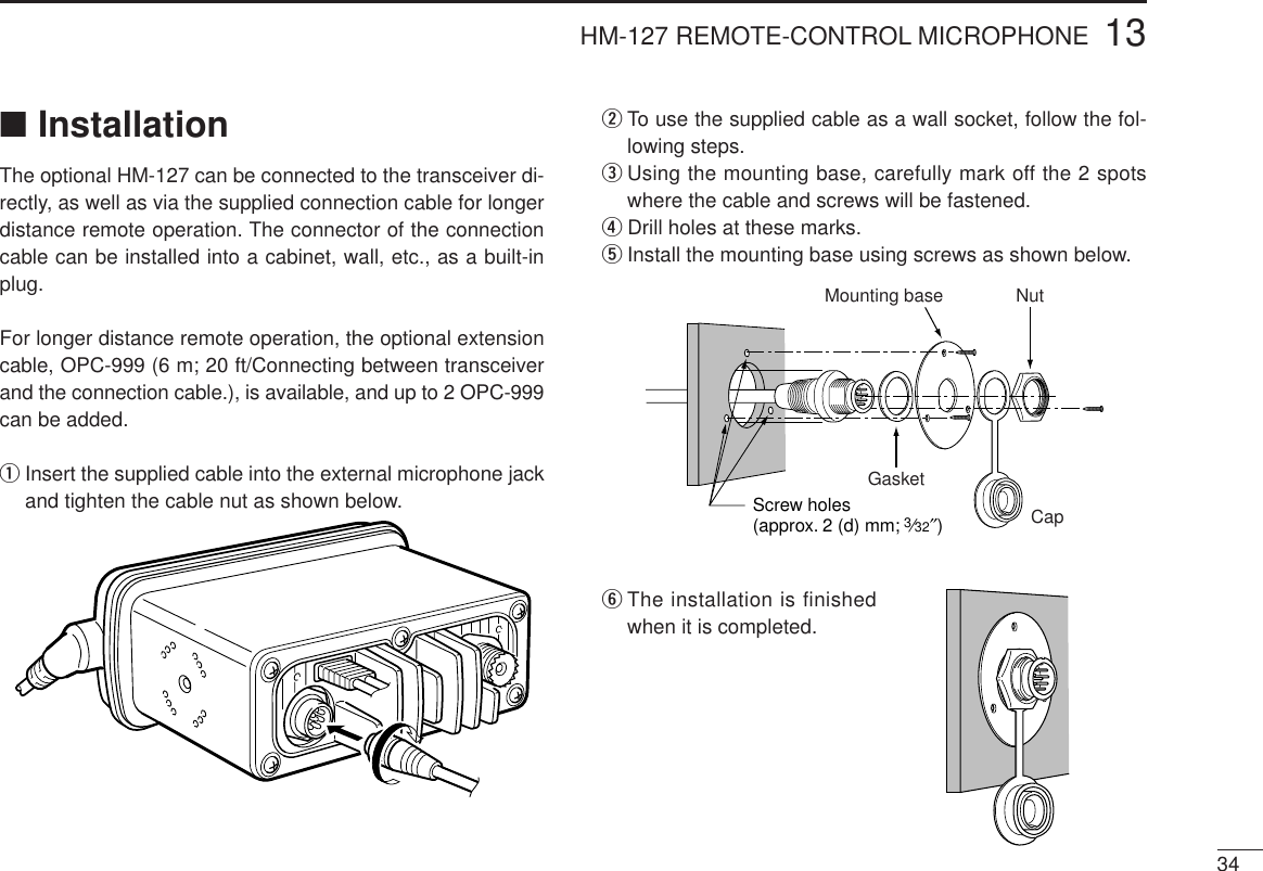
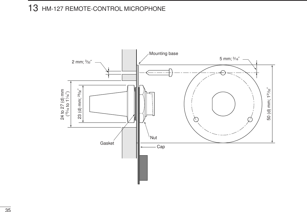
![3013HM-127 REMOTE-CONTROL MICROPHONEOPTIONAL■Panel descriptionThe optional HM-127 remotely controls the IC-M402 and pro-vides an optional intercom function.qPOWER SWITCH [PWR] (p. 6, 44)Push for 2 sec. to turn the HM-127 power ON or OFFwhen the IC-M402 power is turned ON.wPTT SWITCH [PTT] (p. 8, 44)Push and hold to transmit; release to receive.eCHANNEL UP/DOWN SWITCHES [YY]/[ZZ] ➥Push either switch to change the operating channel, setmode contents, etc. (p. 8, 44)➥While pushing [H/L], push [Y]/[Z] to adjust the bright-ness of the LCD and switch backlight. (p. 45)➥Push either switch to adjust audio level or noise squelchlevel after [VOL] or [SQL] is pushed, respectively. (p. 8, 45)➥In set mode, changes setting of the selected item.(p. 9, 46)➥Checks tag channels or changes scanning direction dur-ing scan. (p. 8, 45)rChannel 16/CALL CHANNEL SWITCH [16•9]➥Selects Channel 16 when pushed. (p. 6, 43)➥Selects call channel when pushed for 1 sec. (p. 6, 543)•“CALL” appears when call channel is selected.➥Push for 3 sec. to enter call channel programming con-dition when call channel is selected. (p. 9, 46)➥While pushing [H/L], enters memory name programmingcondition. (p. 9, 49)➥Enters set mode when pushed while turning power ON.(p. 26, 48)qwreuytio!0](https://usermanual.wiki/ICOM-orporated/IC-M402.Manual/User-Guide-132805-Page-35.png)
![3113 HM-127 REMOTE-CONTROL MICROPHONEtCHANNEL/DUALWATCH/TRI-WATCH SWITCH[CH/WX•DW•U/I/C]➥Selects and toggles the regular channels and weatherchannel when pushed momentarily. (p. 6, 7, 43)➥While pushing [H/L], selects one of 3 regular channelsin sequence when pushed. (p. 6, 7, 43)•International, U.S.A. and Canadian channels are available forregular channels.➥Starts dualwatch or tri-watch when pushed for 1 sec. (p. 11, 47)➥Stops dualwatch or tri-watch when either is activated.yATTENUATOR/INTERCOM/SCRAMBLER SWITCH[LO/DX•IC•SCR]➥Activates the intercom function when pushed for 1 sec.(p. 25, 49)➥Calls the IC-M402 when pushed and held while in inter-com mode. (p. 25, 49)•RF attenuator and voice scrambler are not available for IC-M402. uSQUELCH/MONITOR/LOCK SWITCH [SQL•MONI•L] ➥[Y]/[Z] sets the squelch threshold level after pushing[SQL]. (p. 44)➥Push [SQL•MONI] for 1 sec. to turn the monitor functionON. (p. 45)➥While pushing [H/L], push [SQL•MONI•L] to toggle themicrophone key lock function ON or OFF. (p. 45)•“ T” appears while key lock function is in use.•[PWR], [PTT], [VOL], [SQL] and [H/L] still function when themicrophone key lock function is turned ON.➥Advance the cursor while in memory name program-ming condition. (p. 9, 49)iVOLUME/DIMMER SWITCH [VOL•DIM] ➥[Y]/[Z] adjusts the audio level after pushing [VOL]. ➥Push [VOL•DIM] for 1 sec. to adjust the brightness ofthe LCD and switch backlight. (p. 45)➥Move the cursor backward while in memory name pro-gramming condition. (p. 9, 49)oTRANSMIT POWER SWITCH [H/L] ➥Toggles high and low power when pushed. (p. 8, 44)•Some channels are set to low power only.➥While pushing this switch, other switches perform sec-ondary functions.➥Toggles the all key lock function ON or OFF whenpushed while turning power ON. (p. 44)•“ T” flashes while the all key lock function is in use.•Only [PWR] and [PTT] function when the all key lock functionis in use.!0 SCAN SWITCH [SCN•TAG] (p. 13, 46)➥Starts and stops normal or priority scan when tag chan-nels are programmed.➥Push [SCN•TAG] for 1 sec. to set the displayed channelas a tag (scanned) channel. ➥While pushing [H/L], push for 3 sec. to clear all tag chan-nels.](https://usermanual.wiki/ICOM-orporated/IC-M402.Manual/User-Guide-132805-Page-36.png)
![3613HM-127 REMOTE-CONTROL MICROPHONE■Channel selection◊Channel 16qPush [16] to select Channel 16.wPush [CH/WX] to return to thecondition before selecting Chan-nel 16, or push [Y] or [Z] to se-lect operating channel.◊Call channelqPush [16•9] for 1 sec. to selectcall channel.wPush [CH/WX] to return to thecondition before selecting callchannel, or push [Y] or [Z] to se-lect operating channel.◊Weather channelsqPush [CH/WX] once or twice toselect weather channel group.wPush [Y] or [Z] to select weatherchannel.ePush [CH/WX] to return to thecondition before selecting theweather channel group.◊U.S.A., International and CanadianchannelsqPush [CH/WX] to select regular channel.•Push [CH/WX] again, if weather channel appears.wPush [CH/WX•U/I/C], while pushing [H/L], to select chan-nel group.•U.S.A., International and Canadian channels can be selected inPushPush for 1 sec.PushPush while pushingU.S.A. channelsCanadian channelsInternational channels++](https://usermanual.wiki/ICOM-orporated/IC-M402.Manual/User-Guide-132805-Page-41.png)
![3713 HM-127 REMOTE-CONTROL MICROPHONE■Receiving and transmittingqPush [PWR] to turn power ON.wPush [VOL], then [Y]/[Z] to adjust audio output level.•Push [SQL], then [Y]/[Z] to mute any audio noise, if necessary.ePush [Y]/[Z] to select the desired channel.•When receiving a signal, “ ” appears and audio is emittedfrom the speaker.•Further adjustment of audio level may be necessary at this point.rPush [H/L] to select the output power, if necessary.•“LOW” appears when low power is selected.•Choose low power for shorter, high power for longer distancecommunications.•Some channels are low power only.tPush and hold [PTT] to transmit, then speak into the mi-crophone.•“ ” appears.•Channel 70 cannot be used for transmission (for GMDSS use).Simplex channels, 3, 21, 23, 61, 64, 81, 82 and 83 CAN-NOT be lawfully used by the general public in U.S.A. wa-ters.yRelease [PTT] to receive.IMPORTANT: To maximize the readability of your trans-mitted signal (voice), pause a few sec. after pushing [PTT],hold the microphone 10 to 15 cm (4 to 6 inches) from yourmouth and speak at a normal voice level.•Tri-watch becomes dualwatch when receiving a signal on the callchannel.w Set volumew Set squelch, if requiredr Set output powert Speak into microphoneq Turn power ONe Set channelt Push to transmity Release to receive](https://usermanual.wiki/ICOM-orporated/IC-M402.Manual/User-Guide-132805-Page-42.png)
![3813HM-127 REMOTE-CONTROL MICROPHONE■Lock functionsThe lock function electronically locks keys and switches toprevent accidental changes and function access from the mi-crophone.•All keys, switches and controllers on the transceiver are functional.◊Activating the lockfunction➥Push [SQL] while pushing[H/L] to turn the lock functionON and OFF.•“ ” appears.•Only [PWR], [PTT], [H/L],[SQL•MONI], [VOL]+[Y]/[Z] and[SQL]+[Y]/[Z] are functional.◊Activating the all keylock function➥Turn the power ON by pushing[PWR] while pushing [H/L] toturn the all key lock functionON and OFF.•“ ” flashes.•Only [PWR] and [PTT] are functional.■Display backlightingThe function display and switches can be backlit for bettervisibility under low light conditions. And the backlighting con-dition can be adjusted independently from the transceiver.qPush [VOL•DIM] for 1 sec. to enter backlight adjustingmode.•“ ” with number of backlight level appears in the channel nameindicator.wPush [Y]/[Z] to adjust the backlight level.•The backlight level is adjustable between 0 (lights OFF) and 7(brightest).For your reference:Pushing [Y]/[Z], while [H/L] is pushed, also adjusts backlightlevel.•No backlight level indication is available.■Monitor functionThe monitor function releases the noise squelch mute of themicrophone only. (An independent noise squelch system isemployed.)➥Push [SQL•MONI] for 1 sec. to activate the monitor func-tion.•“ ” flashes and audio is emitted.•Any key, except [Y]/[Z], cancels the monitor function.Appears when the lockfunction is in use. Flashes when the all lockfunction is in use.](https://usermanual.wiki/ICOM-orporated/IC-M402.Manual/User-Guide-132805-Page-43.png)
![3913 HM-127 REMOTE-CONTROL MICROPHONE■Call channel programming.qPush [CH/WX•U/I/C] several timeswhile pushing [H/L] to select thedesired channel group (USA, INT,CAN) to be programmed.wPush [16•9] for 1 sec. to select thecall channel of the selected chan-nel group.•“CALL” and call channel number ap-pear.ePush [16•9] again for 3 sec. (untillong beep changes to 2 shortbeeps) to enter call channel pro-gramming condition.•Call channel number and channelgroup to be programmed flashes.rPush [Y]/[Z] to select the desiredchannel.tPush [16•9] to program the dis-played channel as the call channel.•The call channel number and channelgroup stop flashing.■Starting a scanqPush [CH/WX•U/I/C] several times while pushing [H/L] toselect the channel group (USA, INT, CAN), if desired.•When the weather alert function is in use, select the desiredweather channel with [CH/WX] and [Y]/[Z].wPush [SCN] to start priority or normal scan.•“SCAN” appears during normal scan.•The priority channel readout indicates “16”, and “P” and “SCAN”indicators appear during priority scan.•When a signal is received, scan pauses until the signal disap-pears or resumes after pausing 5 sec. according to set mode set-ting (Channel 16 is still monitored during priority scan).•Push [Y]/[Z] to check the scanning tag channels, to change thescanning direction or resume the scan manually.eTo stop the scan, push [SCN].•“SCAN” disappears.•Pushing [PTT], [16•9] or [CH/WX] also stops the scan.■Setting tag channelsqPush [CH/WX•U/I/C] several times while pushing [H/L] toselect the channel group (USA, INT, CAN), if desired.wPush [Y]/[Z] to select the desired channel to set as a tagchannel.ePush [SCN•TAG] for 1 sec. to set the displayed channel asa tag channel.•“ ” appears.](https://usermanual.wiki/ICOM-orporated/IC-M402.Manual/User-Guide-132805-Page-44.png)
![13HM-127 REMOTE-CONTROL MICROPHONE40rTo cancel the tag channel setting, push [SCN•TAG] for1 sec.•“ ” disappears.•Clearing all tag channels in the selected channel group➥Push [SCN•TAG] while pushing [H/L] for 3 sec. (until longbeep changes to 2 short beeps).■Dualwatch/Tri-watch operationqPush [Y]/[Z] to select the desired channel.•Push [CH/WX•U/I/C] several times while pushing [H/L] to selectthe channel group (USA, INT, CAN), if desired.wPush [CH/WX•DW] for 1 sec. to start dualwatch or tri-watch.•“DUAL” appears during dualwatch; “TRI” appears during tri-watch.•Beep tone sounds when a signal is received on Channel 16.•Tri-watch becomes dualwatch when receiving a signal on the callchannel.eTo cancel dualwatch/tri-watch, push [CH/WX•DW] again.■Set mode programmingSet mode is used to change the condition of the transceiver’sfunctions and the microphone’s own functions:In this section, instructions are for the microphone’s own func-tions only. Refer p. 30–33 for the setting of the other func-tions. (Some functions may not be selected from the micro-phone.)◊Entering set modeqTurn power OFF.wWhile pushing [16•9], turn power ON.•After beep emission, a set mode item (in the channel name indi-cator and condition in the channel number readout) is displayed.ePush [16•9] to select the desired item, if necessary.rPush [Y]/[Z] to select the desired condition of the item.tTurn power OFF, then ON to exit set mode.•Beep tone “BEEP”➥Push [Y] to turn ON,[Z] to turn OFF the beepoutput. •LCD contrast “LCD CONTRAST”➥Push [Y]/[Z] to adjustto a suitable LCD contrast.PushPush• •• •](https://usermanual.wiki/ICOM-orporated/IC-M402.Manual/User-Guide-132805-Page-45.png)
![4113 HM-127 REMOTE-CONTROL MICROPHONE■Intercom operationqPush [LO/DX•IC] for 1 sec. to ac-tivate the intercom function.•“IC” appears in the priority channelreadout.•The channel name disappears.wPush [PTT] to talk.•“ ” appears in the channelname indicator.eRelease [PTT] to listen.•“ ” appears in the channel name indicator when the trans-ceiver is in talking mode.rPush [LO/DX•IC] to cancel the intercom function.•Pushing [16], [SCN•TAG] or [CH/WX] is also cancels the inter-com function.For your reference:In case the intercom mode is selected with the transceiverduring microphone power OFF, the microphone power is au-tomatically turned ON and the intercom mode is selected.◊Intercom beep function➥Push [LO/DX•IC] for more than 1 sec.•Emits intercom beep while holding.■Channel namesqPush [Y]/[Z] to select a channel to program.•Push [CH/WX•U/I/C] several times while pushing [H/L] to selectthe channel group (USA, INT, CAN), if desired.wWhile pushing [H/L], push [16•9].•The 1st character of the currently programmed comment flashes.ePush [Y]/[Z] to select a character.rPush [SQL] to move to right; then push [Y]/[Z] to select acharacter.•Push [VOL] to move to the left.tContinue until the desired characters have been selected,then push [16•9] to return to normal operation.•Available characters(r)(s) (t) (u) (v) (w) (x) (y) (z)(q)(3)(D)(N)(X)(h)(+)(4)(E)(O)(Y)(i)(–)(5)(F)(P)(Z)(j)(✱)(6)(G)(Q)(a)(k)(/)(7)(H)(R)(b)(l)(,)(8)(I)(S)(c)(m)(space)(9)(T)(d)(n)(0)(A)(U)(e)(o)(1)(B)(V)(f)(p)(2)(C)(J) (K) (L)(M)(W)(g)(.)( ))(( )(’)(&)(%)($)(#)(")(!)Appears when the inter-com function is in use.](https://usermanual.wiki/ICOM-orporated/IC-M402.Manual/User-Guide-132805-Page-46.png)