ICOM orporated IC-M402 Non-Brodcast Marine Transceiver User Manual IC M402 R s
ICOM Incorporated Non-Brodcast Marine Transceiver IC M402 R s
Contents
- 1. Manual
- 2. Revised Manual 2
Manual

INSTRUCTION MANUAL
iM402
VHF MARINE TRANSCEIVER
This device complies with Part 15 of the FCC rules. Operation is sub-
ject to the following two conditions: (1) This device may not cause
harmful interference, and (2) this device must accept any interference
received, including interference that may cause undesired operation.

i
READ ALL INSTRUCTIONS carefully and completely
before using the transceiver.
SAVE THIS INSTRUCTION MANUAL —This in-
struction manual contains important operating instructions
for the IC-M402.
The installation of this equipment should
be made in such a manner as to respect
the EC recommended electromagnetic
field exposure limits (1999/519/EC).
The maximum RF power available from this device is 25
watts. The antenna should be installed as high as possible
for maximum efficiency and that this installation height
should be at least 6 meters above ground (or accessible)
level. In the case where an antenna cannot be installed at
a reasonable height, then the transmitter should neither
be continuously operated for long periods if any person is
within 6 meters of the antenna, nor operated at all if any
person is touching the antenna. If the antenna cannot be
installed at 6 meters or graterI, we recommend touse the
one watt setting to minimize RF exposure.
In all cases any possible risk depends on the transmitter
being activated for long periods. (actual recommendation
limits are specified as an average of 6 minutes) Normally
the transmitter is not active for long periods of time. Some
radio licenses will require that a timer circuit automatically
cuts the transmitter after 1–2 minutes etc.
CAUTION
IMPORTANTNOTE FOR RF SAFETY

IN CASE OF EMERGENCY
ii
If your vessel requires assistance, contact other vessels and
the Coast Guard by sending a distress call on Channel 16.
Or, transmit your distress call using digital selective calling on
Channel 70.
USING DIGITAL SELECTIVE CALLING (Ch 70)
DISTRESS CALL PROCEDURE
1. While lifting up the switch cover, push and
hold [DISTRESS] for 5 sec. until you hear 5
short beeps change to one long beep.
2. Wait for an acknowledgment from a coast
station.
•Channel 16 is automatically selected.
3. Push and hold [PTT], then transmit the
appropriate information as at left.
USING CHANNEL 16
DISTRESS CALL PROCEDURE
1. “MAYDAY MAYDAY MAYDAY.”
2. “THIS IS ...............” (name of vessel)
3. Your call sign or other indication of the vessel
(AND 9-digit DSC ID if you have one).
4. “LOCATED AT ...............” (your position)
5. The kind of the distress and assistance
required.
6.Any other information which might facilitate
the rescue.

SAFETY TRAINING INFORMATION ......... i
IMPORTANT .............................................. i
IN CASE OF EMERGENCY ...................... ii
TABLE OF CONTENTS ........................... iii
CAUTIONS .............................................. iv
1 OPERATING RULES .................. 1
2 PANEL DESCRIPTION .......... 2–4
■Panel description ............................ 2
■Function display .............................. 3
■Microphone ..................................... 4
3 BASIC OPERATION .............. 5–7
■Channel selection ........................... 5
■Microphone lock function ................ 6
■Receiving and transmitting ............. 6
■Call channel programming .............. 7
■Channel names .............................. 7
4 DUALWATCH/TRI-WATCH ......... 8
■Description ............................................ 8
■Operation ........................................ 8
5 SCAN OPERATIONS ........... 9–10
■Scan types ...................................... 9
■Setting tag channels ..................... 10
■Starting a scan .............................. 10
6 DSC OPERATION .............. 11–18
■MMSI code programming ............. 11
■MMSI code check ......................... 21
■Position indication ......................... 11
■Distress call .................................. 12
■Transmitting DSC calls ................. 13
■DSC individual ID ......................... 16
■Receiving DSC calls ..................... 17
7 INTERCOM OPERATION ......... 19
■Intercom operation ........................ 19
8 SET MODE ........................ 20–21
■Set mode programming ................ 20
■Set mode items ............................. 20
9 CONNECTIONS AND
MAINTENANCE ................. 22–25
■Supplied accessories .................... 22
■Antenna ........................................ 22
■Fuse replacement ......................... 22
■Cleaning ....................................... 22
■Connections .................................. 23
■Mounting the transceiver .............. 24
■Dimensions.................................... 25
10 TROUBLESHOOTING .............. 26
11 CHANNEL LIST ........................ 27
12 SPECIFICATIONS AND
OPTIONS ............................ 28–29
■Specifications ............................... 28
■Options ......................................... 29
13 HM-127 REMOTE-CONTROL
MICROPHONE ................... 30–41
■Panel description .......................... 30
■Function display ............................ 32
■HM-127 supplied accessories ...... 33
■Installation .................................... 34
■Channel selection ......................... 36
■Receiving and transmitting ........... 37
■Lock functions ............................... 38
■Display backlighting ...................... 38
■Monitor function ............................ 38
■Call channel programming ............ 39
■Starting a scan .............................. 39
■Setting tag channels ..................... 39
■Dualwatch/Tri-watch operation ..... 40
■Set mode programming ................ 40
■Intercom operation ........................ 41
■Channel names ............................ 41
TEMPLATE
iii
TABLE OF CONTENTS

iv
RWARNING! NEVER connect the transceiver to an AC
outlet. This may pose a fire hazard or result in an electric
shock.
CAUTION: Changes or modifications to this device, not ex-
pressly approved by Icom Inc., could void your authority to
operate this device under FCC regulations.
NEVER connect the transceiver to a power source of more
than 16 V DC or use reverse polarity. This will ruin the trans-
ceiver.
NEVER cut the DC power cable between the DC plug and
fuse holder. If an incorrect connection is made after cutting,
the transceiver may be damaged.
NEVER place the transceiver where normal operation of the
vehicle may be hindered or where it could cause bodily injury.
KEEP the transceiver at least 3.3 ft (1 m) away from the
ship’s navigation compass.
DO NOT use or place the transceiver in areas with temper-
atures below –4°F (–20°C) or above +140°F (+60°C) or, in
areas subject to direct sunlight, such as the dashboard.
AVOID the use of chemical agents such as benzine or al-
cohol when cleaning, as they may damage the transceiver
surfaces.
BE CAREFUL! The transceiver rear panel will become
hot when operating continuously for long periods.
Place the transceiver in a secure place to avoid inadvertent
use by children.
BE CAREFUL! The transceiver and optional HM-127 em-
ploy waterproof construction, which corresponds to JIS wa-
terproof specification, grade 7 (1 m/30 min.). However, once
the transceiver or microphone has been dropped, water-
proofing cannot be guaranteed due to the fact that the case
may be cracked, or the waterproof seal damaged, etc.
CAUTIONS

1
1OPERATING RULES
◊PRIORITIES
•Read all rules and regulations pertaining to priorities and
keep an up-to-date copy handy. Safety and distress calls
take priority over all others.
•You must monitor channel 16 when you are not operating on
another channel.
•False or fraudulent distress signals are prohibited and pun-
ishable by law.
◊PRIVACY
•Information overheard but not intended for you cannot law-
fully be used in any way.
•Indecent or profane language is prohibited.
◊RADIO LICENSES
(1) SHIP STATION LICENSE
You must have a current radio station license before using the
transceiver. It is unlawful to operate a ship station which is not
licensed.
Inquire through your dealer or the appropriate government
agency for a Ship-Radiotelephone license application. This
government-issued license states the call sign which is your
craft’s identification for radio purposes.
(2) OPERATOR’S LICENSE
A Restricted Radiotelephone Operator Permit is the license
most often held by small vessel radio operators when a radio
is not required for safety purposes.
The Restricted Radiotelephone Operator Permit must be
posted or kept with the operator. Only a licensed radio opera-
tor may operate a transceiver.
However, non-licensed individuals may talk over a transceiver
if a licensed operator starts, supervises, ends the call and
makes the necessary log entries.
Keep a copy of the current government rules and regulations
handy.
Radio license for boaters (U.S.A. only)
The Telecommunications Act of 1996 permits recreational
boaters to have and use a VHF marine radio, EPIRB, and
marine radar without having an FCC ship station license.
Boaters travelling on international voyages, having an HF
single sideband radiotelephone or marine satellite terminal,
or required to carry a marine radio under any other regula-
tion must still carry an FCC ship station license. For further
information, see the FCC Ship Radio Stations Fact Sheet.

2
2
PANEL DESCRIPTION
■Panel description
Speaker Function display wu
qertyi
qCHANNEL UP / DOWN SWITCHES [YY] / [ZZ]
➥Push to select the operating channels, set mode con-
tents, etc. (p. 6)
➥While pushing [H/L], push [Y] / [Z] to adjust the bright-
ness of the LCD and switch backlight.
➥Push for 1sec. to start/stop scanning(p. 9)
➥Push [Y] and [Z] for 1sec. to toggle the tag setting for
the displayed channel. (p. 10)
wPOWER / VOLUME CONTROL [VOL]
Turns power ON and OFF and adjusts the audio level. (p. 6)
eSQUELCH CONTROL [SQL]
Sets the squelch threshold level. (p. 6)
rTRANSMIT POWER SWITCH [H/L]
➥Toggles high and low power when pushed. (p. 6)
•Some channels are set to low power only.
➥While pushing this switch, other switches perform sec-
ondary functions.
tCHANNEL SWITCH [CH/WX•DUAL]
➥Selects and toggles the regular channels and weather
channel when pushed momentarily. (p. 5)
➥While pushing [HI/LO], selects one of 3 regular channels
in sequence when pushed. (p. 5)
•International, U.S.A. and Canadian channels are available for
regular channels.
➥Starts dualwatch or tri-watch when pushed for 1 sec.
(p. 8)
➥Stops dualwatch or tri-watch when either is activated.
yCHANNEL 16/CALL CHANNEL SWITCH [16•9]
➥Selects channel 16 when pushed. (p. 5)
➥Selects call channel when pushed for 1 sec. (p. 5)
•“CALL” appears when call channel is selected.
➥Push for 3 sec. to enter call channel programming con-
dition when call channel is selected. (p. 7)
➥While pushing [H/L], enters memory name programming
condition. (p. 7)
➥Enters set mode when pushed while turning power ON.
(p. 20)
uDISTRESS SWITCH [DISTRESS]
Transmits distress call when pushed for 5 sec. (p. 17)
iDSC/POSITION SWITCH [DSC/ENT•POS]
➥Selects the DSC menu when pushed. (p. 11)
➥Shows current position and time from an optional GPS
receiver, etc. when pushed for 1 sec. (p. 11)
3
2PANEL DESCRIPTION
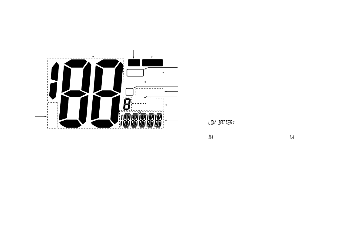
■Function display
qTRANSMIT INDICATOR (p. 6)
“TX” appears while transmitting.
wBUSY INDICATOR (p. 6)
“BUSY” appears when receiving a signal or when the
squelch opens.
eTAG CHANNEL INDICATOR (p. 10)
Appears when a tag channel is selected.
rCALL CHANNEL INDICATOR
“CALL” appears when the call channel is selected. (p. 5)
tLOW POWER INDICATOR (p. 6)
“LOW” appears when low power is selected.
yDUPLEX INDICATOR (p. 5)
Appears when a duplex channel is selected.
uWEATHER CHANNEL INDICATOR (p. 5, 36)
➥“WX” appears when a weather channel is selected.
➥“ALT” appears when the weather alert function is in use;
flashes when an alert tone is received.
iGPS INDICATOR
➥“GPS” appears while valid position data is received.
➥“GPS” blinks when invalid position data is received.
➥“GPS” disappears when no GPS receiver is connected.
oDSC INDICATOR
➥Indicates the DSC status. (p. 14)
!0 CHANNEL NAME INDICATOR
➥Channel comment appears if programmed. (p. 7)
➥“ ” scrolls when the battery voltage drops to
approx. 10 V DC or below.
➥“ ” appears during dualwatch; “ ” appears during
tri-watch. (p. 8)
!1 CHANNEL NUMBER READOUT
➥Indicates the selected operating channel number. “A”
appears when a simplex channel is selected. (p. 5)
➥In set mode, indicates the selected condition. (p. 20)
!2 CHANNEL GROUP INDICATOR (p. 5)
Indicates whether a U.S.A. (USA), International (INT), or
Canadian (CANADA) channel is in use.
U
C
I
LOW
DWX ALT
CALL
BUSY
BUSY
TXTX
TAG
GPS DSC
POS REPLY
wq
e
r
t
y
i
o
u
!0
!1
!2

PANEL DESCRIPTION
4
2
■Microphone
qPTT SWITCH [PTT]
Push and hold to transmit; release to receive. (p. 6)
wCHANNEL UP/DOWN SWITCHES [YY]/[ZZ]
Push either switch to change the operating memory chan-
nel, set mode contents, etc. (p. 6)
eCHANNEL 16/CALL CHANNEL SWITCH [16•9]
➥Same as the [H/L] switch on the front panel. (p. 6)
➥Selects channel 16 when pushed. (p. 5)
➥Selects call channel when pushed for 1 sec. (p. 5)
•“CALL” appears when call channel is selected.
➥Push for 3 sec. to enter call channel programming con-
dition when call channel is selected. (p. 7)
➥While pushing [H/L], enters memory name programming
condition. (p. 7)
➥While pushing [16] on the supplied microphone, turn
power ON to toggle the lock function ON and OFF. (p. 6)
Microphone
w
q
e
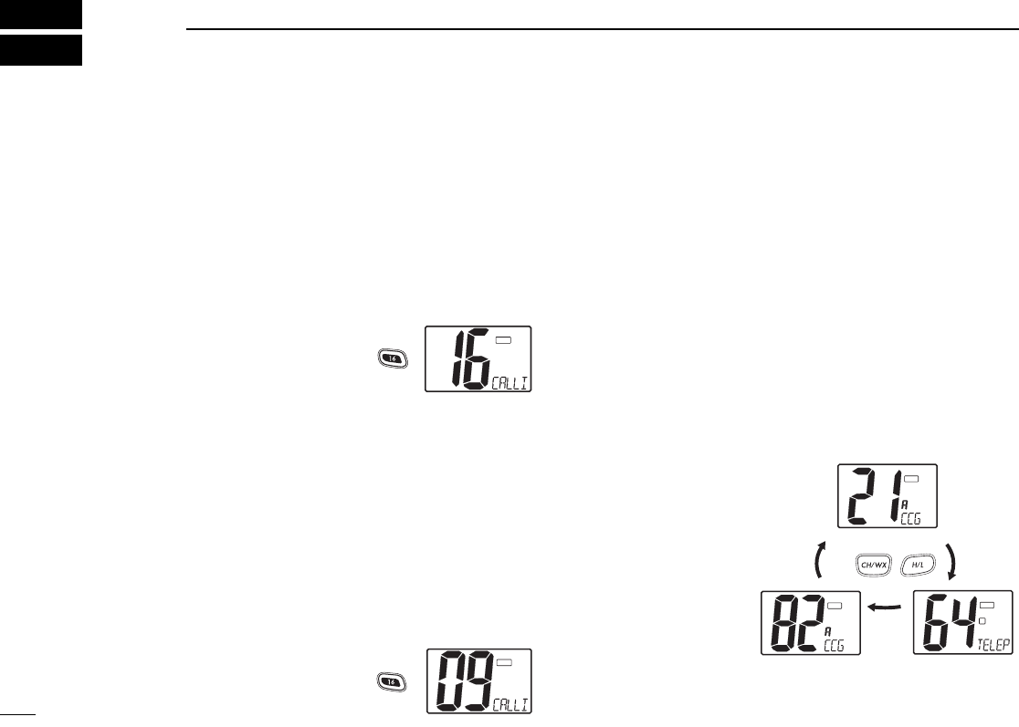
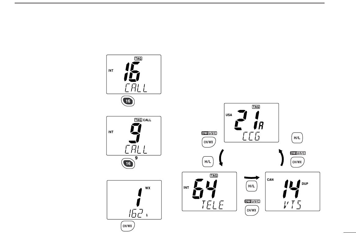
■Channel selection
◊Channel 16
Channel 16 is the distress and safety channel. It is used for
establishing initial contact with another station and for emer-
gency communications. Channel 16 is monitored during both
dualwatch and tri-watch. While standing by, you must monitor
channel 16.
➥Push [16 ] momentarily to select channel 16.
➥Push [CH/WX] to return to the
condition before selecting chan-
nel 16, or push [Y] / [Z] to se-
lect an operating channel.
◊Channel 9 (Call channel)
Each regular channel group has a separate leisure-use call
channel. The call channel is monitored during tri-watch. The
call channels can be programmed (p. 7) and are used to store
your most often used channels in each channel group for
quick recall.
➥Push [16] for 1 sec. to select the call channel of the se-
lected channel group.
•“CALLING” and call channel number appear.
•Each channel group may have an independent call channel.
➥Push [CH/WX] to return to the
condition before selecting call
channel,or push [Y] / [Z] to
select an operating channel.
◊U.S.A., Canadian and international channels
There are 57 U.S.A., 61 Canadian and 57 international chan-
nels. These channel groups may be specified for the operat-
ing area.
qPush [CH/WX] to select a regular channel.
•If a weather channel appears, push [CH/WX] again.
wPush [CH/WX] while pushing [H/L] to change the channel
group, if necessary.
•U.S.A., International (INT) and Canadian channels can be se-
lected in sequence.
eRotate the channel selector to select a channel.
•“D” appears for duplex channels.
•“A” appears for simplex channels.
5
3BASIC OPERATION
I
TAG
Push
I
CALL
TAG
Push
Push +
U.S.A. channels
Canadian channels International channels
C
TAG
I
D
TAG
U
TAG
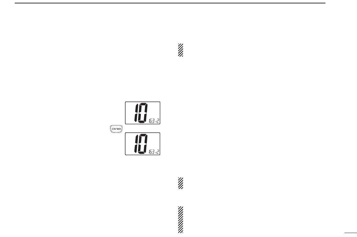
◊Weather channels
There are 10 weather channels. Used for monitoring weather
channels from the NOAA (National Oceanographic and At-
mospheric Administration) broadcasts.
The transceiver can detect a weather alert tone on the se-
lected weather channel while receiving the channel, during
standby on a regular channel or while scanning. (p. 20)
qPush [CH/WX] once or twice to select a weather channel.
•“WEATHER” appears when a
weather channel is selected.
“WX ALT” appears when the
weather alert function is in use.
(p. 20)
wRotate the channel selector to
select a channel.
•Channels are memorized sepa-
rately for each channel group
■Microphone lock function
The microphone lock function electrically locks the [Y]/[Z]
and [16] switches on the supplied microphone. This prevents
accidental channel changes and accidental function access.
➥While pushing [16] on the supplied microphone, turn power
ON to toggle the lock function ON and OFF.
3
BASIC OPERATION
6
Push
once
or
twice
When weather alert is OFF.
When weather alert is ON.
WX
WX ALT
■Receiving and transmitting
CAUTION: Transmitting without an antenna may dam-
age the transceiver.
qTurn [VOL] right to turn power ON.
wSet the audio and squelch levels.
➥Rotate [SQL] fully counterclockwise in advance.
➥Rotate [VOL] to adjust the audio output level.
➥Rotate [SQL] clockwise until the noise disappears.
ePush [Y]/[Z] to select the desired channel. (p. 5)
•When receiving a signal, “BUSY” appears and audio is emitted
from the speaker.
rPush [H/L] to select the output power if necessary.
•“LOW” appears when low power is selected.
•Choose high power for longer distance communications.
•Some channels are for low power only.
tPush and hold [PTT] to transmit, then speak into the mi-
crophone.
•“TX” appears.
•Channel 70 cannot be used for transmission (for GMDSS use).
Simplex channels, 3, 21, 23, 61, 64, 81, 82 and 83 CAN-
NOT be lawfully used by the general public in U.S.A. waters.
yRelease [PTT] to receive.
IMPORTANT: To maximize the readability of your trans-
mitted signal, pause a few sec. after pushing [PTT], hold
the microphone 4 to 6 inches (10 to 15 cm) from your
mouth and speak at a normal voice level.
3BASIC OPERATION
7
■Call channel programming
The call channel is used to select Channel 9, however, you
can program your most often-used channels in each channel
group for quick recall.
qWhile pushing [H/L], push [CH/WX] one or more times to
select the desired channel group (U.S.A., International,
Canada) to be programmed.
wPush [16 ] for 1 sec. to select the call channel of the se-
lected channel group.
•“CALL” and call channel number appear.
ePush [16 ] again for 3 sec. (until
long beep changes to 2 short
beeps) to enter call channel pro-
gramming condition.
•Channel number starts flashing.
rPush [Y]/[Z] to select the de-
sired channel.
tPush [16 ] to program the dis-
played channel as the call chan-
nel.
•Push [CH/WX] to cancel.
•The channel number stops flashing.
■Channel names
Memory channels can be tagged with alphanumeric names
of up to 10 characters each.
Capital letters, small letters, numerals, some symbols (! " # $
% & ' ( ) ✱+ ,– .⁄) and spaces can be used.
qSelect the desired memory channel.
•Cancel dual watch, tri-watch or scan in advance.
wWhile pushing [H/L], push [16 ] to edit memory channel
name.
•A cursor appears and blinks.
eSelect the desired character by pushing [Y]/[Z].
•Push [CH/WX] or [H/L] for cursor movement.
rPush [16 ] to input and set the name.
•Push [H/L] to cancel.
•The cursor disappears.
tRepeat steps qto rto program other memory channel
names, if desired.
I
CALL
TAG
I
D
CALL
TAG
I
TAG
8
4
DUAL WATCH/TRI-WATCH
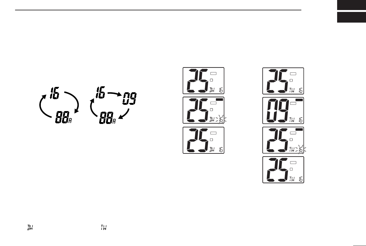
■Description
Dualwatch monitors channel 16 while you are receiving an-
other channel; tri-watch monitors Channel 16 and the call
channel while receiving another channel.
DUALWATCH/TRI-WATCH SIMULATION
•If a signal is received on Channel 16, dualwatch/tri-watch pauses
on Channel 16 until the signal disappears.
•If a signal is received on the call channel during tri-watch, tri-watch
becomes dualwatch until the signal disappears.
•To transmit on the selected channel during dualwatch/tri-watch, push
and hold [PTT].
■Operation
qSelect the desired operating channel.
wSelect dualwatch or tri-watch in set mode. (p. 20)
ePush [CH/WX] for 1 sec. to start dualwatch or tri-watch.
•“ ” appears during dualwatch; “ ” appears during tri-watch.
•Beep tone sounds when a signal is received on Channel 16.
rTo cancel dualwatch/tri-watch, push [CH/WX] again.
Dualwatch Tri-watch
Call channel
Operating tri-watch on INT
channel 25
Operating dual-watch on INT
channel 25
Dual-watch starts.
I
D
TAG
Signal received on
channel 16 takes
priority.
I
D
BUSY
BUSY
TAG
Dual-watch resumes
after the signal
disappears.
I
D
TAG
Tri-watch starts.
Signal is received
on call channel.
Signal received on
channel 16 takes
priority.
Tri-watch resumes
after the signal
disappears.
I
D
TAG
I
D
BUSY
BUSY
TAG
I
CALL
BUSY
BUSY
TAG
I
D
TAG
[Example]
9
■Scan types
Scanning is an efficient way to locate signals quickly over a
wide frequency range. The transceiver has priority scan and
normal scan.
When the weather alert function is in use, the selected
weather channel is checked while scanning. (p. 20)
Set the tag channels (scanned channel) before scanning.
Clear the tag channels which inconveniently stop scanning,
such as digital communication use.
Choose priority or normal scan in set mode. (p. 20)
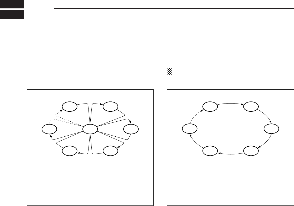
NORMAL SCAN
Normal scan, like priority scan, searches through all tag
channels in sequence. However, unlike priority scan, Chan-
nel 16 is not checked unless Channel 16 is set as a tag
channel.
CH 01 CH 02
CH 06
CH 05 CH 04
CH 03
5SCAN OPERATIONS
PRIORITY SCAN
Priority scan searches through all tag channels in se-
quence while monitoring Channel 16. When a signal is de-
tected on Channel 16, scan pauses until the signal disap-
pears; when a signal is detected on a channel other than
Channel 16, scan becomes dualwatch until the signal dis-
appears.
CH 06
CH 01
CH 16
CH 02
CH 05 CH 04
CH 03

10
5
SCAN OPERATION
Scan starts. When a signal is receiv
e
I
D
TAG
I
D
TAG
I
D
BU
SYBUSY
TAG
[Example]: Starting a priority scan.
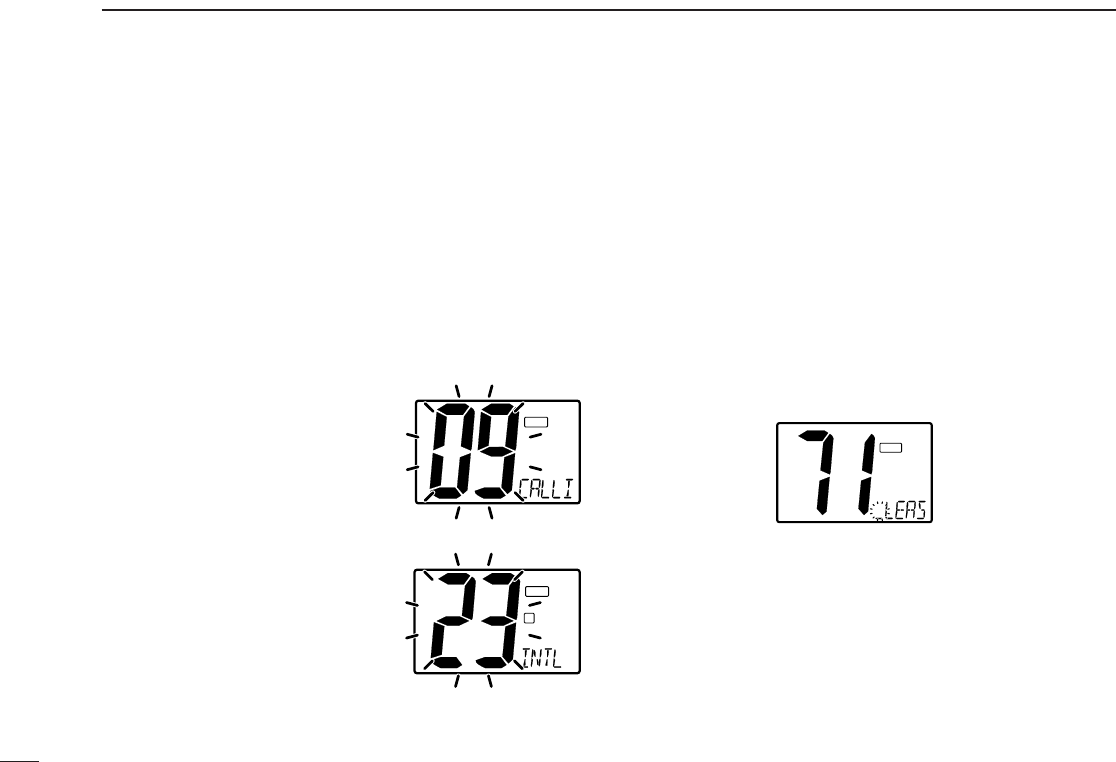
■Setting tag channels
For more efficient scanning, add desired channels as tag
channels or clear tag channels for unwanted channels. Chan-
nels set as non-tag channels will be skipped during scanning.
Tag channels can be assigned to each channel group
(U.S.A., International, Canada) independently.
qWhile pushing [H/L], push [CH/WX] one or more times to
select the desired channel group, if desired.
wSelect the desired channel to set as a tag channel.
ePush [Y] and [Z] for 1 sec. to set the displayed channel
as a tag channel.
•“TAG” appears in the function display.
rTo cancel the tag channel setting, repeat e.
•“TAG” disappears.
•Clearing all tag channels in the selected channel group
➥While pushing [Y] and [Z], Turn power ON to clear all tag
channels in the channel group.
■Starting a scan
Set scan type (priority or normal scan) and scan resume timer
in advance using set mode. (p. 20)
qSet tag channels as described at left.
wMake sure the squelch is closed to start a scan.
eWhile pushing [H/L], push [CH/WX] one or more times to
select the desired channel group, if desired.
rPush [Y] or [Z] for 1 sec. to start priority or normal scan.
•“Pri scan 16” or “Normal scan” appears in the function display.
•When a signal is detected, scan pauses until the signal disap-
pears or resumes after pausing 5 sec. according to set mode set-
ting. (Channel 16 is still monitored during priority scan.)
•Rotate the channel selector to check the scanning tag channels,
to change the scanning direction or resume the scan manually.
•“16” flashes and a beep tone sounds when a signal is received
on Channel 16 during priority scan.
•Push [Y] and [Z] for 1 sec. to set the paused channel as a tag
channel.
tTo stop the scan, push [Y] or [Z].
Push
[Y] or [Z]
for 1 sec.
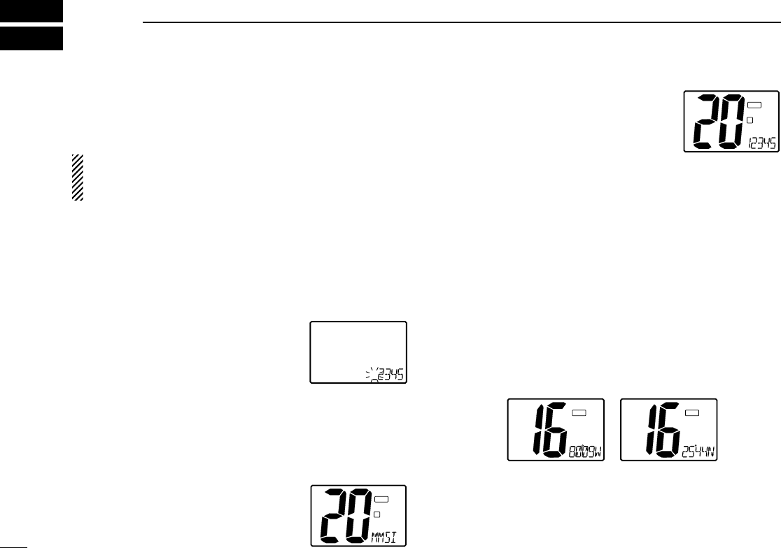
■MMSI code programming
The 9-digit MMSI (DSC self ID) code can be programmed at
power ON.
This function is not available when the MMSI code has
been programmed by the dealer. This code programming
can be performed only 2 times.
qTurn power OFF.
wWhile pushing [DSC], turn power ON to enter MMSI code
programming condition.
eAfter the display appears, release [DSC].
rSelect the desired number by pushing [Y]/[Z] .
tPush [CH/WX] to advance the cursor.
•Push [H/L] to move the cursor backward.
yRepeat steps rand tto input 9 digit
code.
uPush [DSC] to input and set the code.
•The previously selected channel appears.
■MMSI code check
The 9-digit MMSI (DSC self ID) code can be checked.
qPush [DSC] to select the DSC menu.
wPush [Y]/[Z] to select “MMSI” and
push [DSC].
eCheck the 9-digit MMSI (DSC self ID)
code.
rPush [DSC] to exit the condition.
■Position indication
When an optional GPS receiver (NMEA0183 ver. 2.0) is con-
nected, the transceiver can display the current position and time.
A GPS receiver appropriate for the IC-M402 is not supplied from
Icom. An NMEA0183 ver. 2.0 is required for position indication.
Ask your dealer about the GPS receiver.
➥While pushing [H/L], push [DSC] for 1 sec. to display the cur-
rent position.
•“Latitude and longitude are displayed alternately.
I
TAG
GPS
I
TAG
GPS
11
6DSC OPERATION
I
D
TAG
I
D
TAG
12
6
DSC OPERATION
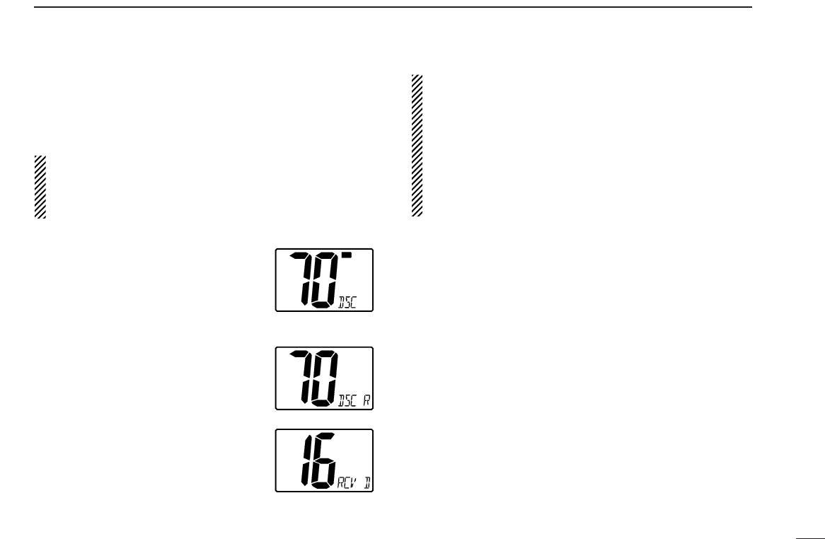
■Distress call
A distress call should be transmitted if, in the opinion of the
Master, the ship or a person is in distress and requires imme-
diate assistance.
NEVER USE THE DISTRESS CALL WHEN
YOUR SHIP IS NOT IN AN EMERGENCY. A
DISTRESS CALL CAN BE USED ONLY WHEN
IMMEDIATE HELP IS NEEDED.
qConfirm any distress call is not being received.
wWhile lifting up the switch cover, push
the [DISTRESS] switch for 5 sec. to
transmit the distress call.
•An emergency channel (Ch 70) is auto-
matically selected and the distress call is transmitted..
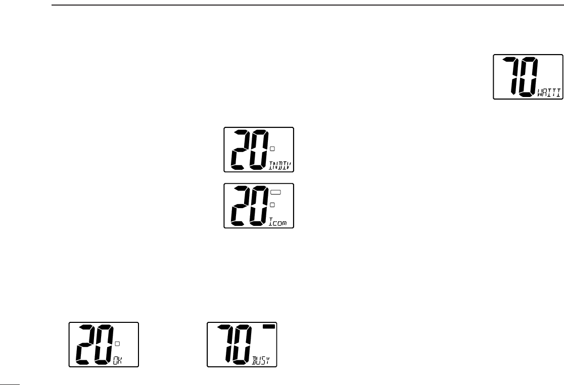
eAfter transmitting the call, the transceiver waits for an ac-
knowledgment call on Ch70.
•The distress call is automatically transmit-
ted every 3.5 to 4.5 minutes.
•”DSC RPEAT” scrolls.
rWhen receiving the acknowledgment,
reply to the connected station via the
microphone.
•”RCV Distress ACK” scrolls.
➥Distress alert contains (default);
•Kinds of distress : Undesignated distress
•Position data : Latest GPS position data held for 23.5 hrs.
or until the power is turned OFF.
➥The distress call is repeated every 3.5–4.5 min., until re-
ceiving an ‘acknowledgement.’
➥Push [DISTRESS] to transmit a renewed distress call, if
desired.
➥Push [16] to cancel the ‘Call repeat’ mode.
I
TX
TX
I
LOW
I
DSC
13
■Transmitting DSC calls
◊Transmitting individual call
The individual call function allows you to transmit a DSC sig-
nal to a specific party only.
qSelect a desired channel other than
Channel 70.
wPush [DSC] to select the DSC menu
ePush [Y]/[Z] to select “individual” and
push [DSC].
rPush [Y]/[Z] to select the desired pre-
programmed individual address.
•The ID code for the individual call can be
set in advance. (p. 22)
tPush [DSC] to enter pre-programmed individual address.
•‘OK’ appears.
yPush [DSC] to transmit the individual call.
•Channel 70 is selected and the individual call is transmitted to
the selected station.
•If Channel 70 is busy, the transceiver stands by until the channel
becomes clear.
•Routine category only is available.
Push [DSC] to transmit DSC CALL. When Ch 70 is busy.
uStan dby on Channel 70 until an ac-
knowledgement is received.
•”WAITING ACK” scrolls.
iWhen the acknowledgement is re-
ceived, the display changes to the previously selected user
channel with beeps.
oPush and hold [PTT] to communicate your message to the
responding party.
I
BUSY
BUSY
I
LOW
D
6DSC OPERATION
I
LOW
D
I
LOW
D
TAG
I
LOW
14
6
DSC OPERATION
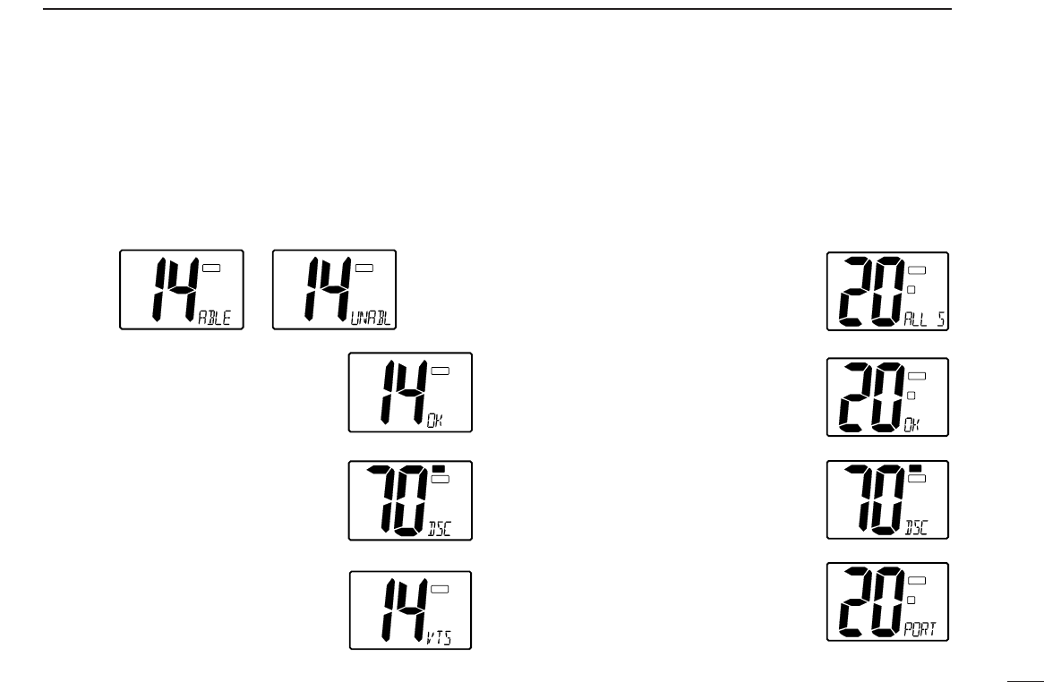
◊Transmitting individual acknowledgement
Transmit an acknowledgement (‘able to comply’ or ‘unable to
comply’) when an individual call for you is received.
q“RCV Individual” scrolls.
wPush [Y] or [Z] to select the acknowledgement “ABLE” or
“UNABLE”.
ePush [DSC] to enter selected individ-
ual call acknowledgement, “OK” ap-
pears.
rPush [DSC] to.transmit individual call
acknowledgement
tIf you select “Able”,the channel speci-
fied by the calling stationl is automati-
cally selected.
◊Transmitting all ships call
Large ships use Channel 70 as their “listening channel.”
When you want to announce a message to these ships, use
the “all ships call” function.
qSelect a desired channel other than Channel 70.
wPush [DSC] to select the DSC menu
ePush [Y]/[Z] to select “ALL SHIPS”.
•Routine category only is available.
rPush [DSC] to enter all ships call.
•‘OK’ appears.
tPush [DSC] to transmit the all ships
call.
•Channel 70 is selected and the all ships
call is transmitted.
•Routine category only is available.
yThe all ships call has been transmit-
ted.
•A previous channel is selected automati-
cally.
uPush [PTT] or [Y]/[Z] to exit the condition.
I
TAG
DSC
I
TX
TX
TAG
I
TAG
I
TAG
DSC
I
TAG
DSC
I
D
TAG
I
D
TAG
I
LOW
TXTX
TAG
I
D
TAG
15
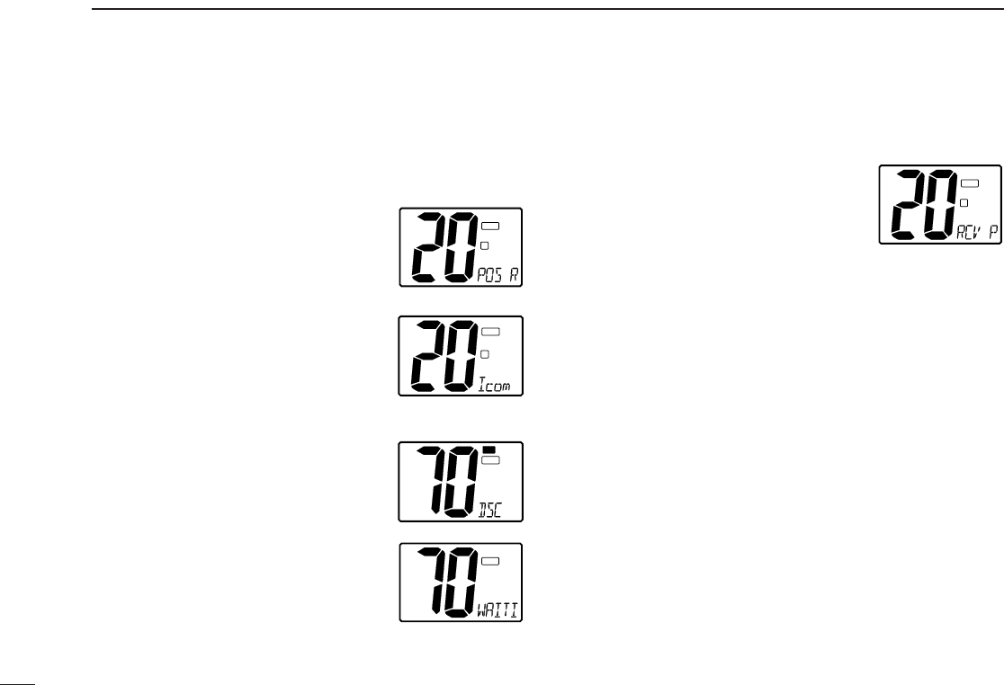
◊Transmitting position request call
Transmit a position request call when you want to know your
friend’s current position, etc.
qSelect a desired channel other than Channel 70.
wPush [DSC] to select the DSC menu
ePush [Y]/[Z] to select “POS RE-
QUEST”.
rPush [Y]/[Z] to select the desired pre-
programmed individual address.
•The ID code for position request can be
set in advance. (p. 22)
tPush [DSC] to enter pre-programmed individual address.
•“OK” appears.
yPush [DSC] to transmit the position
request call.
•Channel 70 is selected and the position
request call is transmitted.
uThe position request call has been
transmitted.
•”WAITING ACK” scrolls.
iPush [PTT] or rotate the channel selector to exit the condi-
tion.
◊Transmitting position reply call
Transmit a position reply call when a position request call is
received.
q”DSC” appears and a“RCV Pos re-
quest” scrolls in the display.
wPush [DSC] to reply to the position request call; push [H/L]
to ignore the position request call.
6DSC OPERATION
I
D
TAG
I
LOW
D
TAG
I
TX
TX
TAG
I
LOW
TAG
I
D
TAG
DSC
16
6
DSC OPERATION
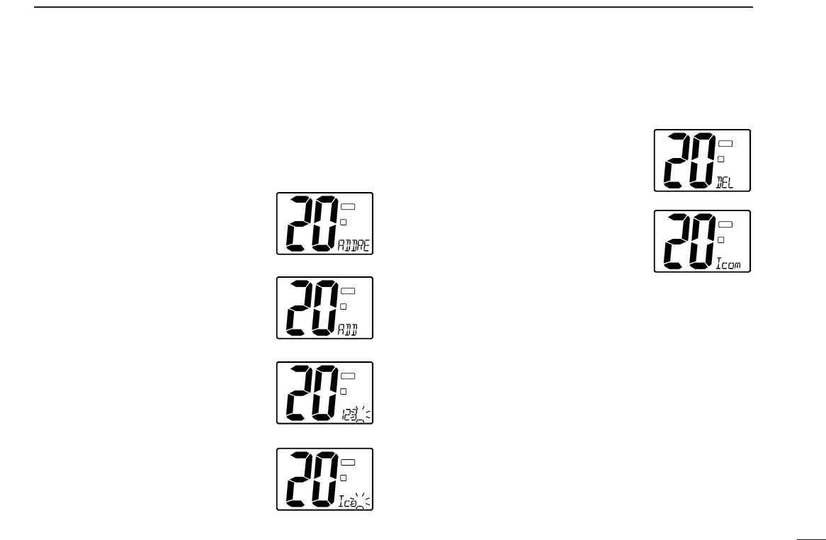
■DSC individual ID
A total of 40 DSC address ID’s can be programmed and
named with up to 10 characters.
◊Programming address ID
qPush [DSC] to select the DSC menu.
wPush [Y]/[Z] to select “ADDRESS”
and push [DSC].
ePush [Y]/[Z] to select “ADD” and
push [DSC].
rSet the distress ID and ID name, then
push [DSC/ENT].
• Rotate the channel selector to select the
character.
•Push [H/L] to advance the cursor.
•Push [CH/WX] to move the cursor back-
ward.
•Push [16] to cancel and exit the condition.
•Up to 5 characters available to enter ID
names.
tPush [DSC] to program and to exit the condition.
◊Deleting address ID
qPush [DSC] to select the DSC menu.
wPush [Y]/[Z] to select “ADDRESS” and push [DSC].
ePush [Y]/[Z] to select ‘DEL,’ then
push [DSC].
•When no address ID is programmed, the
transceiver exits the condition automati-
cally.
rSelect the desired ID name pushing
[Y]/[Z], then push [DSC].
tPush [DSC] to delete the address ID;
push an other switch to exit the condi-
tion.
I
D
TAG
I
D
TAG
I
D
TAG
I
D
TAG
I
D
TAG
I
D
TAG

17
6DSC OPERATION
■Receiving DSC calls
◊Receiving a distress call
While monitoring Channel 70 and a dis-
tress call is received:
➥Emergency alarm sounds for 2 min-
utes.
•Push any switch to stop the alarm.
➥“DSC” appears and and “RCV Distress” scrolls in the dis-
play, then Channel 16 is automatically selected.
➥Continue monitoring Channel 16 as a coast station may re-
quire assistance.
◊Receiving a distress acknowledgement
While monitoring Channel 70 and a dis-
tress acknowledgement to other ship is
received:
➥Emergency alarm sounds for 2 min-
utes.
•Push any switch to stop the alarm.
➥“RCV Distress ACK” scrolls in the display, then Channel 16
is automatically selected.
◊
Receiving a distress relay acknowledgement
While monitoring Channel 70 and a dis-
tress relay acknowledgement is received:
➥Emergency alarm sounds for 2 min-
utes.
•Push any switch to stop the alarm.
➥“RCV Distress Relay ACK” scrolls in the display; then,
Channel 16 is automatically selected.
◊Receiving a distress relay call
While monitoring Channel 70 and a dis-
tress relay call is received:
➥Emergency alarm sounds for 2 min-
utes.
•Push any switch to stop the alarm.
➥“RCV Distress Relay” appears in the display, then Channel
16 is automatically selected.
➥Monitor Channel 16 until the emergency communication
has been completed.
◊Receiving an all ships call
While monitoring Channel 70 and an all
ships call is received:
➥Emergency alarm sounds when the
category is “Distress” or “Urgency;” 2
beeps sound for other categories.
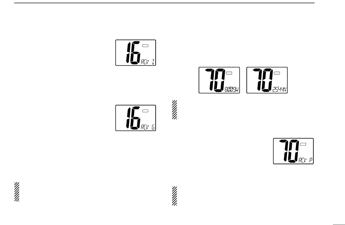
➥“RCV All ships” scrolls in the display; then,the channel
specified by the calling station is automatically selected for
voice communication.
➥Monitor the selected channel for an announcement from
the calling vessel.
I
TAG
DSC
I
TAG
DSC
I
TAG
DSC
I
TAG
DSC
I
TAG
DSC
18
6
DSC OPERATION
◊Receiving an individual call
While monitoring Channel 70 and an in-
dividual call is received:
➥Emergency alarm or beeps sound de-
pending on the received category.
➥“RCV Individual” scrolls in the display, then the channel
specified by the calling station is automatically selected for
checking the channel condition.
◊Receiving a geographical area call
While monitoring Channel 70 and a geo-
graphical area call (for the area you are
in) is received:
➥Emergency alarm or beeps sound de-
pending on the received category.
➥“RCV Geographic” scrolls, then the channel specified by
the calling station is automatically selected for voice com-
munications.
➥Monitor the selected channel for an announcement from
the calling ship.
When no GPS receiver is connected or if there is a prob-
lem with the connected receiver, all geographical area calls
are received, regardless of your position.
◊Receiving a position reply call
While monitoring Channel 70 and a position reply call (for the
area you are in) is received:
➥“Received POS” appears in the display.
•“Latitude and longitude are displayed alternately.
When no GPS receiver is connected or if there is a prob-
lem with the connected receiver, all geographical area calls
are received, regardless of your position.
◊Receiving a position request call
While monitoring Channel 70 and a posi-
tion request call (for the area you are in)
is received:
➥“RCV Pos request” scrolls in the dis-
play.
➥Push [DSC] to reply to the call.
When no GPS receiver is connected or if there is a prob-
lem with the connected receiver, all geographical area calls
are received, regardless of your position.
I
TAG
I
TAG
DSC
POS REPLY DSC
POS REPLY
I
TAG
DSC
I
TAG
DSC
I
TAG
DSC
19
7INTERCOM OPERATION
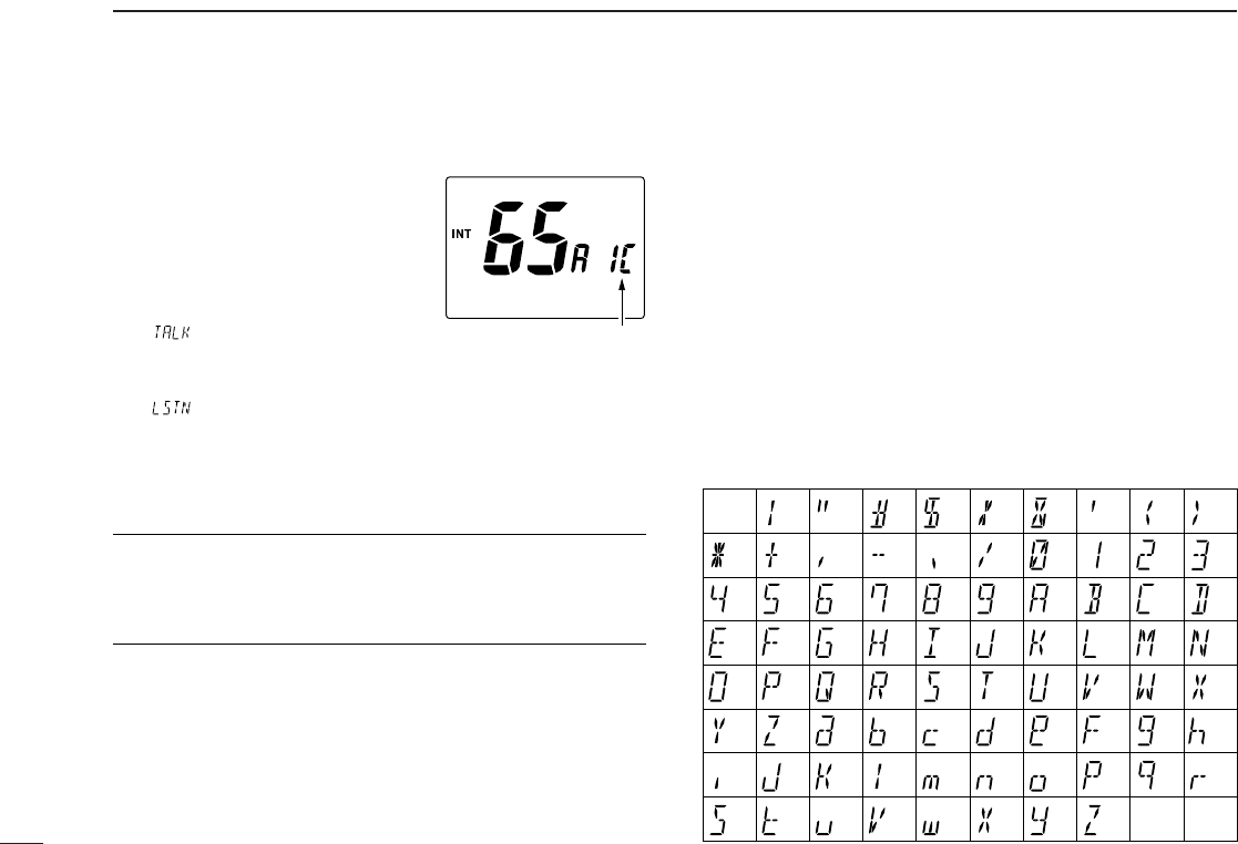
■Intercom operation
The optional intercom function allows you to talk to the deck
from the cabin. The optional HM-127 REMOTE-CONTROL MI-
CROPHONE is required for intercom operation.
Connect an optional HM-127 as described on p. 37.
•Transmitting is impossible during intercom operation.
•The received signal is muted during intercom operation.
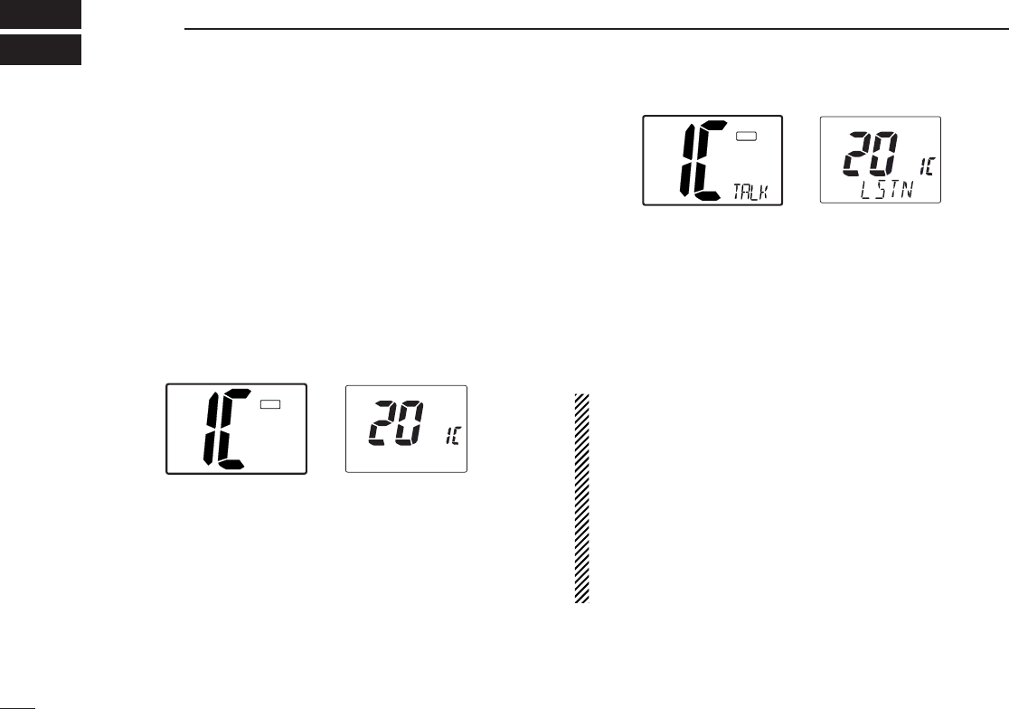
qPush [DSC] for 1 sec. to enter intercom mode.
•The HM-127 power is automatically turned ON, even if the HM-
127 power is OFF.
wPush and hold [DSC] again to call up.
•The transceiver and microphone emit call beeps.
ePush and hold the PTT switch and speak at a normal voice
level into the microphone.
•“TALK” or “LSTN” appears on the caller or listener function dis-
play, respectively.
•To adjust the IC-M402’s speaker output level, rotate [VOL].
•To adjust the HM-127’s speaker output level, push [Y]/[Z] after
pushing [VOL] on the HM-127.
rAfter releasing the PTT switch you can hear the response
through the speaker.
tTo return to normal operation, push [DSC] momentarily.
•Other switches also turn the function OFF, however, the corre-
sponding function is then activated e.g. pushing [16] selects
Channel 16.
•While in the intercom mode, the transceiver functions
(transmit and receive) are interrupted. If the transceiver is
in transmit condition, the intercom function is not avail-
able.
•When a DSC call is received, “DSC received” appears
and the last received DSC message is displayed after the
intercom use is finished.
•When a WX alert is received, “WX ALT” flashes and a
beep sounds. The WX alert sounds after the intercom use
is finished.
INT
HM-127 (listener)
IC-M402 (caller)
I
TAG
INT
HM-127IC-M402
I
TAG
20
8
SET MODE
Scan mode Weather alert
Scan resume timer Dual/tri watch
DSC watch
LCD contrast
WX ALT
Beep tone
Push
■Set mode programming
Set mode is used to change the conditions of some of the
transceiver’s functions.
•Available functions may differ depending on dealer setting.
•The optional HM-127 has it’s own settings for the beep
tone and LCD contrast.
qTurn power OFF.
wWhile pushing [16], turn power ON to enter set mode.
eAfter the display appears, release [16].
rPush [16] to select the desired item, if necessary.
tPush [Y]/[Z] to select the desired condition of the item.
yTurn power OFF, then ON again to exit set mode.
•SET MODE CONSTRUCTION
■Set mode items
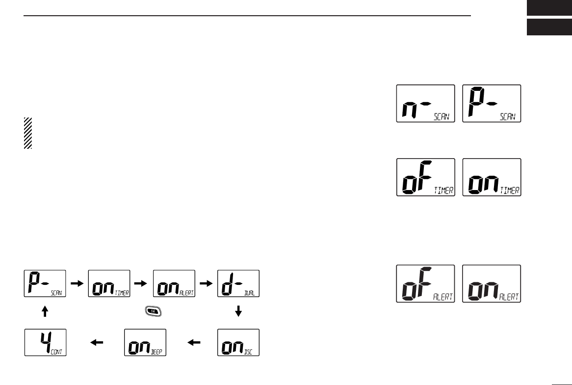
◊Scan mode
The scan mode can be se-
lected as a normal scan or
priority scan. (p. 9)
◊Scan resume timer
The scan resume timer can
be selected as a pause
(OFF) or timer scan (ON).
When OFF is selected, the
scan pauses until the signal
disappears. When ON is selected, the scan pauses 5 sec. and
resumes even if a signal is being received on channels except
for Channel 16.
◊Weather alert
An NOAA broadcast sta-
tion transmits a weather
alert tone before important
weather information. When
the weather alert function is turned ON, the transceiver detects
the alert, then flashes the “WX ALT” indicator until the trans-
ceiver is operated. The previously selected (used) weather
channel is checked any time during standby or while scanning.
•“ALT” appears with “WX” indication when the function is set ON.
Normal scan (default) Priority scan
Scan timer OFF (default) Scan timer ON
Weather alert ON
WX ALT
Weather alert OFF (default)
WX
21
8SET MODE
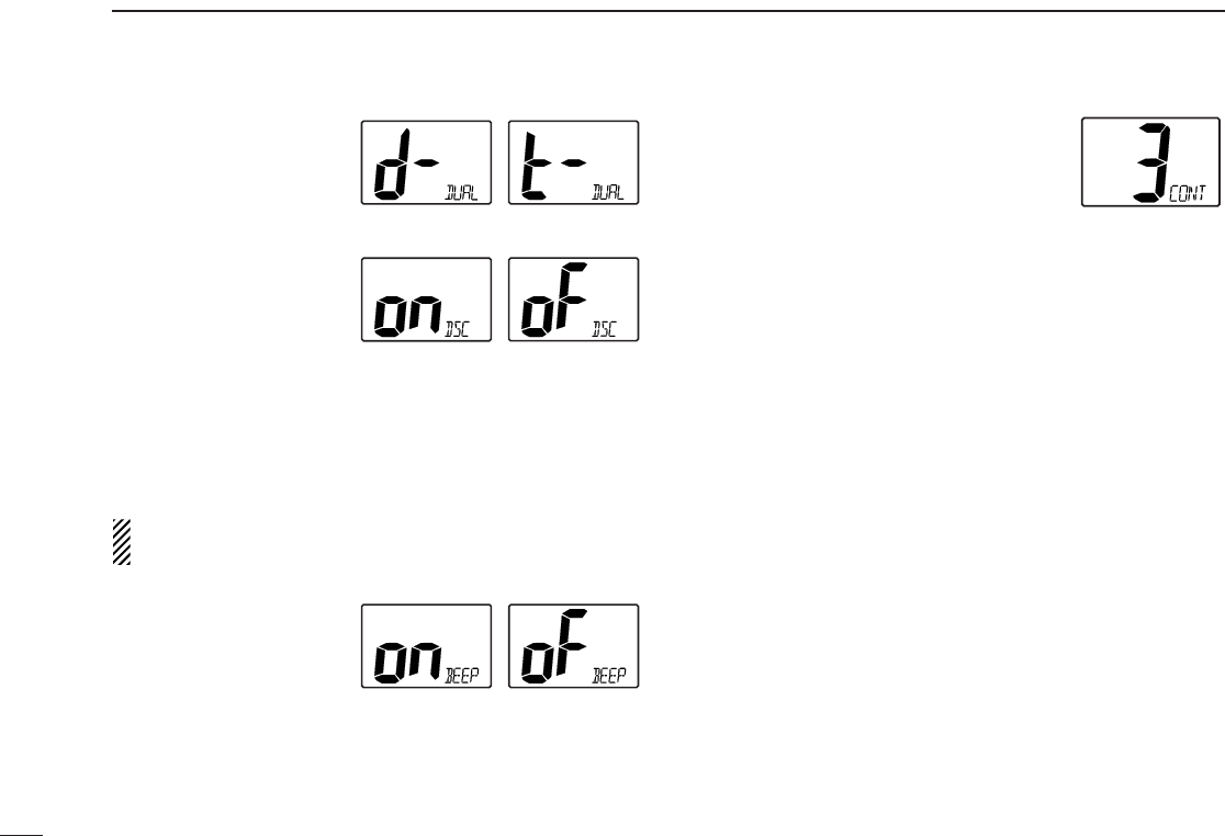
◊Dual/tri watch
This item can be selected
as dual watch or tri-watch.
(p. 8)
◊DSC watch
DSC watch monitors
Channel 70 while you are
receiving another channel.
If a distress signal is received on Channel 70, the transceiver
monitors Channel 16 and 70 alternately until the distress sig-
nal disappears. If a signal is received on another channel,
DSC watch pauses until the signal disappears.
This function may not be available for some channel
groups depending on dealer setting.
◊Beep tone
You can select silent oper-
ation by turning beep
tones OFF or you can
have confirmation beeps
sound at the push of a switch by turning beep tones ON.
◊LCD contrast
This item adjusts the contrast of the LCD
in 4 steps.
Dual watch (default) Tri-watch
DSC watch OFF
DSC watch ON (default)
Beep tone ON (default) Beep tone OFF
LCD contrast 3 (default)
22
9
CONNECTIONS AND MAINTENANCE
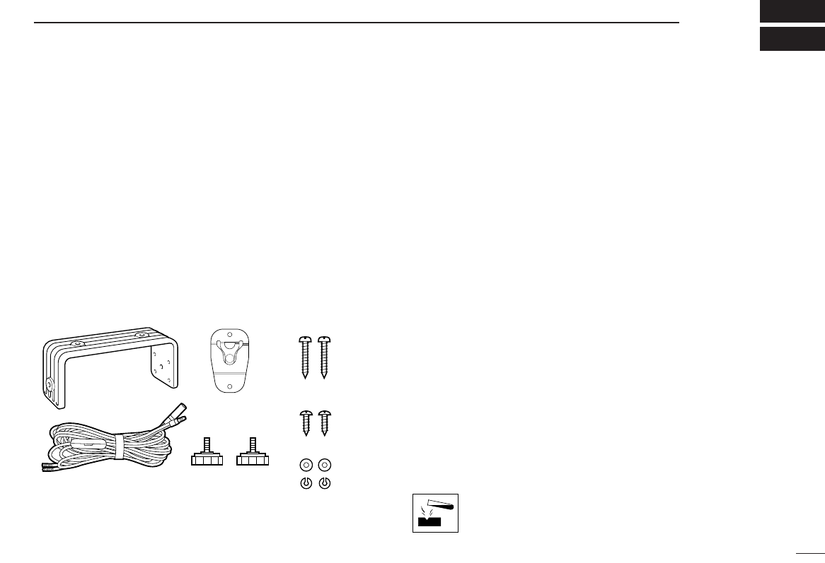
■Supplied accessories
The following accessories are supplied: Qty.
qMounting bracket ............................................................ 1
wDC power cable (OPC-891) ............................................ 1
eMicrophone hanger ......................................................... 1
rMounting bracket knobs ................................................. 2
tMounting screws (5 ×20)................................................ 2
yMic hanger screws (3 ×16) ........................................... 2
uFlat washers (M5) ........................................................... 2
iSpring washers (M5) ...................................................... 2
■Warning sticker attachment
A WARNING STICKER is supplied with the transceiver.
To comply with FCC regulations, this sticker must be affixed in
such a location as to be readily seen from the operating con-
trols of the radio. Make sure the chosen location is clean and
dry before applying the sticker.
■Antenna
A key element in the performance of any communication sys-
tem is an antenna. Ask your dealer about antennas and the
best places to mount them.
■Fuse replacement
One fuse is installed in the supplied DC power cable. If a fuse
blows or the transceiver stops functioning, track down the
source of the problem, if possible, and replace the damaged
fuse with a new, rated one.
■Cleaning
If the transceiver becomes dusty or dirty, wipe it clean with a
soft, dry cloth.
AVOID the use of solvents such as benzene or al-
cohol, as they may damage transceiver surfaces.
➀➂
➁➃
➄
➅
➆
➇
23
9CONNECTIONS AND MAINTENANCE
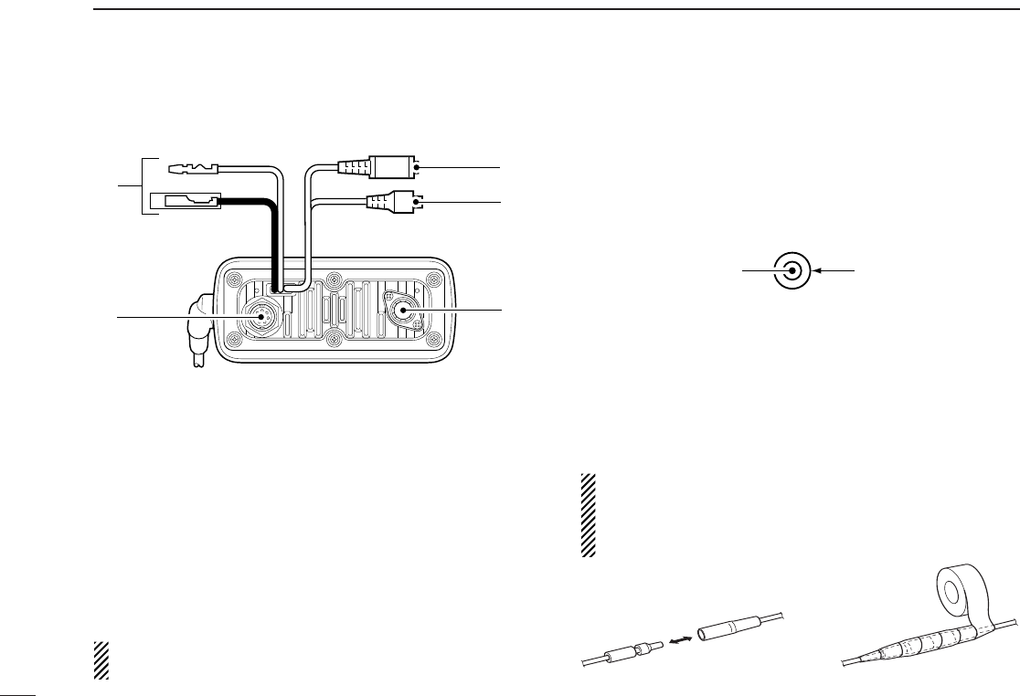
■Connections
qDC POWER CONNECTOR
Connects the supplied DC power cable from this connector
to an external 12 V DC power source.
wEXTERNAL MICROPHONE JACK
Connects to optional HM-127 REMOTE-CONTROL MICRO-
PHONE.
eANTENNA CONNECTOR
Connects a marine VHF antenna with a PL-259 connector
to the transceiver.
CAUTION: Transmitting without an antenna may dam-
age the transceiver.
rGPS RECEIVER JACK
Connects to an optional GPS receiver to input the position
data and time data.
•A GPS receiver appropriate for the IC-M402 is not supplied from
Icom. An NMEA0183 ver. 2.0 is required for position or time indi-
cation, etc. Ask your dealer about the GPS receiver.
tEXTERNAL SPEAKER JACK
Connects to an external speaker. See ‘Options’ on p. 30
for available external speakers.
MICROPHONE HANGER
Rest the supplied microphone on the hanger when not in
use.
CAUTION: After connecting the DC power cable, GPS
receiver jack and external speaker jack, cover the connec-
tor and jacks with an adhesion tape as shown below, to
prevent water seeping into the transceiver.
Adhesion
tape
NMEA (+)
RCA
NMEA (—)
r
q
t
e
w
24
9
CONNECTIONS AND MAINTENANCE
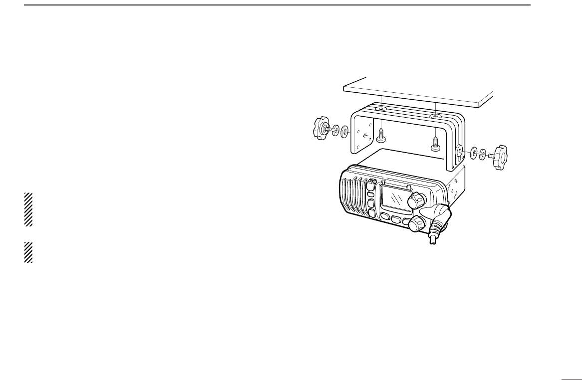
■Mounting the transceiver
◊Using the supplied mounting bracket
The universal mounting bracket supplied with your transceiver
allows overhead or dashboard mounting.
•Mount the transceiver securely with the 2 supplied screws
(M5 ×20) to a surface which is more than 10 mm thick and
can support more than 5 kg.
•Mount the transceiver so that the face of the transceiver is at
90° to your line of sight when operating it.
CAUTION: KEEP the transceiver and microphone at
least 1 meter away from your vessel’s magnetic navigation
compass.
NOTE: Check the installation angle; the function display
may not be easy-to-read at some angles.
EXAMPLE
25
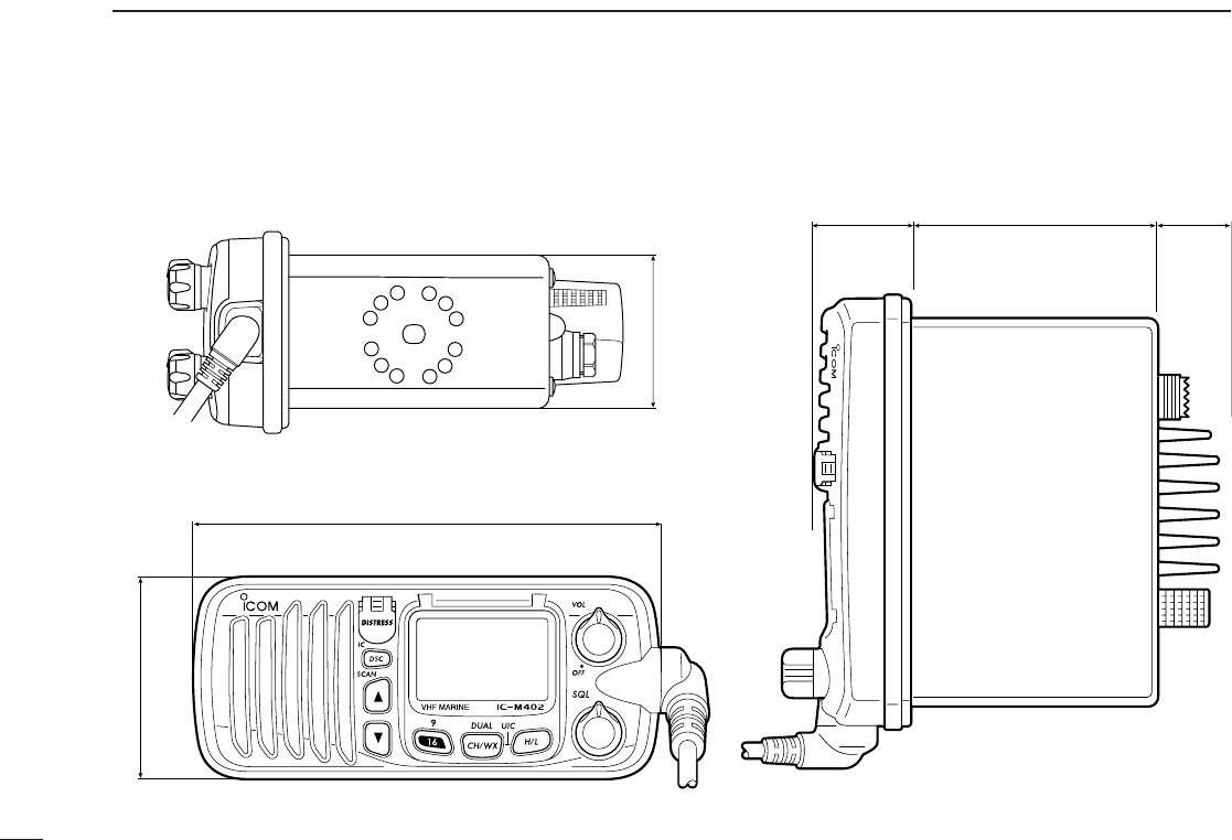
■Dimensions
152 mm (6 in)
67 mm (2 58 in)
28.5 mm
(1 18 in) 86.5 mm (3 13 32 in) 25 mm
(1 in)
51 mm (2 in)
9CONNECTIONS AND MAINTENANCE

PROBLEM REF.POSSIBLE CAUSE SOLUTION
No power comes ON.
No sound comes from
the speaker.
Scan does not start.
Transmitting is impossi-
ble, or high power can-
not be selected.
No beep sounds.
Distress call cannot be
transmitted.
•Squelch level is too deep.
•Volume level is too low.
•Speaker has been exposed to water.
•Bad connection to the power supply.
•Some channels are for low power or
receive only.
•The output power is set to low.
•TAG channel is not programmed.
•Beep tone is turnd OFF.
•The squelch is open.
•MMSI (DSC self ID) code is not pro-
grammed.
•Check the connection to the transceiver.
•Set squelch to the threshhold point.
•Set [VOL] to a suitable level.
•Drain water from the speaker.
•Change channels.
•Push [H/L] to select high power.
•Set the desired channels as TAG channels.
•Turn the beep tone ON in set mode.
•Set squelch to the threshold point.
•Program the MMSI (DSC self ID) code.
p. 22
p. 6
p. 6
p. 5,27
p. 6
p. 10
p. 21
p. 6
p. 11
26
10
TROUBLESHOOTING

27
Channel number
USA CAN
Transmit
Receive
01 156.050 160.650
01A 156.050 156.050
02 156.100 160.700
03 156.150 160.750
03A 156.150 156.150
156.200 160.800
04A 156.200 156.200
156.250 160.850
05A 05A 156.250 156.250
06 06 156.300 156.300
156.350 160.950
07A 07A 156.350 156.350
08 08 156.400 156.400
09 09 156.450 156.450
10 10 156.500 156.500
11 11 156.550 156.550
12 12 156.600 156.600
13
*2
13
*1
156.650 156.650
14 14 156.700 156.700
15
*2
15
*1
156.750 156.750
16 16 156.800 156.800
17
*1
17
*1
156.850 156.850
156.900 161.500
18A 18A 156.900 156.900
Frequency (MHz)
INT
01
02
03
04
05
06
07
08
09
10
11
12
13
14
15
*1
16
17
18
Channel number Frequency (MHz)
USA CAN
Transmit
Receive
19A 19A 156.950 156.950
20 20
*1
157.000 161.600
21 157.050 161.650
21A 21A 157.050 157.050
157.100 161.700
22A 22A 157.100 157.100
23 157.150 161.750
23A 157.150 157.150
24 24 157.200 161.800
25 25 157.250 161.850
26 26 157.300 161.900
27 27 157.350 161.950
28 28 157.400 162.000
60 156.025 160.625
156.075 160.675
61A 61A 156.075 156.075
156.125 160.725
62A 156.125 156.125
156.175 160.775
63A 156.175 156.175
64 156.225 160.825
INT
20
21
22
23
24
25
26
27
28
60
61
62
63
64
20A 157.000 157.000
Channel number
66A
Frequency (MHz)
66A
*1
USA CAN
Transmit
Receive
64A 64A 156.225 160.825
65A 65A 156.275 156.275
156.325 160.925
67
*2
67 156.375 156.375
68 68 156.425 156.425
69 69 156.475 156.475
70
*3
70
*3
156.525 156.525
71 71 156.575 156.575
72 72 156.625 156.625
73 73 156.675 156.675
74 74 156.725 156.725
77
*1
77
*1
156.875 156.875
156.925 161.525
78A 78A 156.925 156.925
156.975 161.575
79A 79A 156.975 156.975
157.025 161.625
80A 80A 157.025 157.025
157.075 161.675
81A 81A 157.075 157.075
157.125 161.725
82A 82A 157.125 157.125
INT
65A
66
67
68
69
70
*3
71
72
73
74
77
78
79
80
81
82
156.325 156.32566A
Channel number
84A
Frequency (MHz)
USA CAN
Transmit
Receive
83A 83A 157.175 157.175
84 84 157.225 161.825
85 85 157.275 161.875
85A 157.275 157.275
86 86 157.325 161.925
86A 157.325 157.325
87 87 157.375 161.975
87A 157.375 157.375
88 88 157.425 162.025
88A 157.425 157.425
INT
84
85
86
87
88
157.225 157.225
WX channel
4
Frequency (MHz)
Transmit Receive
1RX only 162.550
2RX only 162.400
3RX only 162.475
5RX only 162.450
6RX only 162.500
7RX only 162.525
8RX only 161.650
9RX only 161.775
10 RX only 163.275
RX only 162.425
*1
Low power only.
*3
Receive only.
156.950 161.55019
21b Rx only 161.650
25b Rx only 161.850
156.275 160.87565
28b Rx only 162.000
83 157.175 157.17583
83b Rx only 161.775
*2
Momentary high power.
11 CHANNEL LIST

28
12
SPECIFICATIONS AND OPTIONS
■Specifications
◊General
•Frequency coverage :
Transmit 156.025–157.425 MHz
Receive 156.050–163.275 MHz
•Mode : FM (16K0G3E)
DSC (16K0G2B)
•Channel spacing : 25 kHz
•Current drain (at 13.8 V) : TX high 6.0 A max.
Max. audio 1.2 A max.
•Power supply requirement: 13.8 V DC ±15%
•Frequency stability : ±10 ppm
(–20°C to + 60°C; –4°F to
+140°F)
•Dimensions : 152(W)×67(H)×144(D) mm
(Projection not included) 6(W)×25⁄8(H)×52⁄3(D) in
•Weight : 900 g; 2 lb
◊Transmitter
•Output power : 25 W and 1 W
•Modulation system : Variable reactance phase
modulation
•Max. frequency deviation : ±5.0 kHz
•Spurious emissions : –70 dB
◊Receiver
•Receive system :
Double conversion
superheterodyne
•Sensitivity (12 dB SINAD) : Less than 0.25 µV (typical)
•Squelch sensitivity : Less than 0.20 µV (typical)
•
Intermodulation rejection ratio
: More than 70 dB
•Spurious response : More than 70 dB
rejection ratio
•
Adjacent channel selectivity
: More than 70 dB
•Audio output power : More than 4.5 W at 10% distor-
tion with a 4 Ωload
All stated specifications are subject to change without
notice or obligation.

29
12 SPECIFICATTIONS AND OPTIONS
■Options
•MB-69 FLUSH MOUNT
For mounting the transceiver to a panel.
•SP-5 EXTERNAL SPEAKER
A large, external speaker for superior audio output.
•SP-10 EXTERNAL SPEAKER
A compact, external speaker. Features easy installation.
•HM-127 REMOTE-CONTROL MICROPHONE (p. 30)
External microphone-type controller. Provides optional inter-
com operation. 6 m (20 feet) microphone cable and mount-
ing base included. Black and white colours are available.
•OPC-999 MICROPHONE EXTENSION CABLE
6 m (20 feet) microphone extension cable for optional
HM-127. Up to 2 OPC-999 can be connected. (18 m; 60 feet
maximum)
30
13
HM-127 REMOTE-CONTROL MICROPHONE
OPTIONAL
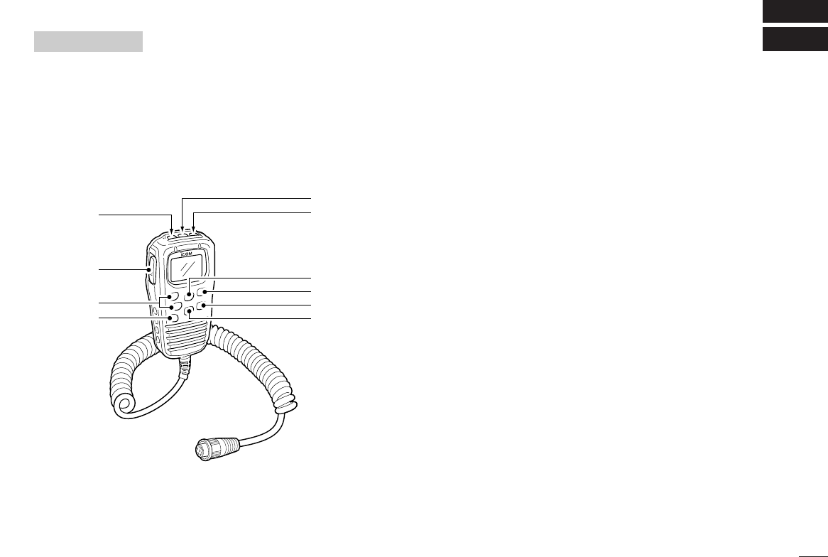
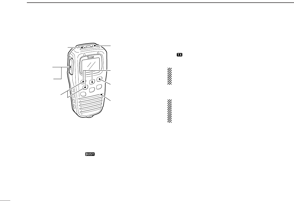
■Panel description
The optional HM-127 remotely controls the IC-M402 and pro-
vides an optional intercom function.
qPOWER SWITCH [PWR] (p. 6, 44)
Push for 2 sec. to turn the HM-127 power ON or OFF
when the IC-M402 power is turned ON.
wPTT SWITCH [PTT] (p. 8, 44)
Push and hold to transmit; release to receive.
eCHANNEL UP/DOWN SWITCHES [YY]/[ZZ]
➥Push either switch to change the operating channel, set
mode contents, etc. (p. 8, 44)
➥While pushing [H/L], push [Y]/[Z] to adjust the bright-
ness of the LCD and switch backlight. (p. 45)
➥Push either switch to adjust audio level or noise squelch
level after [VOL] or [SQL] is pushed, respectively.
(p. 8, 45)
➥In set mode, changes setting of the selected item.
(p. 9, 46)
➥Checks tag channels or changes scanning direction dur-
ing scan. (p. 8, 45)
rChannel 16/CALL CHANNEL SWITCH [16•9]
➥Selects Channel 16 when pushed. (p. 6, 43)
➥Selects call channel when pushed for 1 sec. (p. 6, 543)
•“CALL” appears when call channel is selected.
➥Push for 3 sec. to enter call channel programming con-
dition when call channel is selected. (p. 9, 46)
➥While pushing [H/L], enters memory name programming
condition. (p. 9, 49)
➥Enters set mode when pushed while turning power ON.
(p. 26, 48)
q
w
r
eu
y
t
i
o
!0

31
13 HM-127 REMOTE-CONTROL MICROPHONE
tCHANNEL/DUALWATCH/TRI-WATCH SWITCH
[CH/WX•DW•U/I/C]
➥Selects and toggles the regular channels and weather
channel when pushed momentarily. (p. 6, 7, 43)
➥While pushing [H/L], selects one of 3 regular channels
in sequence when pushed. (p. 6, 7, 43)
•International, U.S.A. and Canadian channels are available for
regular channels.
➥Starts dualwatch or tri-watch when pushed for 1 sec.
(p. 11, 47)
➥Stops dualwatch or tri-watch when either is activated.
yATTENUATOR/INTERCOM/SCRAMBLER SWITCH
[LO/DX•IC•SCR]
➥Activates the intercom function when pushed for 1 sec.
(p. 25, 49)
➥Calls the IC-M402 when pushed and held while in inter-
com mode. (p. 25, 49)
•RF attenuator and voice scrambler are not available for IC-
M402.
uSQUELCH/MONITOR/LOCK SWITCH [SQL•MONI•L]
➥[Y]/[Z] sets the squelch threshold level after pushing
[SQL]. (p. 44)
➥Push [SQL•MONI] for 1 sec. to turn the monitor function
ON. (p. 45)
➥While pushing [H/L], push [SQL•MONI•L] to toggle the
microphone key lock function ON or OFF. (p. 45)
•“ T” appears while key lock function is in use.
•[PWR], [PTT], [VOL], [SQL] and [H/L] still function when the
microphone key lock function is turned ON.
➥Advance the cursor while in memory name program-
ming condition. (p. 9, 49)
iVOLUME/DIMMER SWITCH [VOL•DIM]
➥[Y]/[Z] adjusts the audio level after pushing [VOL].
➥Push [VOL•DIM] for 1 sec. to adjust the brightness of
the LCD and switch backlight. (p. 45)
➥Move the cursor backward while in memory name pro-
gramming condition. (p. 9, 49)
oTRANSMIT POWER SWITCH [H/L]
➥Toggles high and low power when pushed. (p. 8, 44)
•Some channels are set to low power only.
➥While pushing this switch, other switches perform sec-
ondary functions.
➥Toggles the all key lock function ON or OFF when
pushed while turning power ON. (p. 44)
•“ T” flashes while the all key lock function is in use.
•Only [PWR] and [PTT] function when the all key lock function
is in use.
!0 SCAN SWITCH [SCN•TAG] (p. 13, 46)
➥Starts and stops normal or priority scan when tag chan-
nels are programmed.
➥Push [SCN•TAG] for 1 sec. to set the displayed channel
as a tag (scanned) channel.
➥While pushing [H/L], push for 3 sec. to clear all tag chan-
nels.
32
13
HM-127 REMOTE-CONTROL MICROPHONE
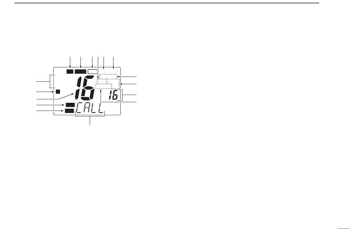
■Function display
qCHANNEL GROUP INDICATOR (p. 6, 37)
Indicates whether an International (INT), U.S.A. (USA) or
Canadian (CAN) channel is selected.
wKEY LOCK INDICATOR (p. 38)
➥Appears while the key lock function is in use.
➥Flashes while the all key lock function is in use.
eCHANNEL NUMBER READOUT
➥Indicates the selected operating channel number. “A”
appears when a simplex channel is selected. (p. 5, 36)
➥In set mode, indicates the selected condition. (p. 20, 40)
rVOLUME INDICATOR (p. 37)
Appears while audio output level is adjusted.
tSQUELCH INDICATOR (p. 37)
Appears while noise squelch level is adjusted.
yCHANNEL NAME INDICATOR
➥Channel comment appears (and scrolls) if programmed.
(p. 7, 41)
➥In set mode, indicates or scrolls the selected set mode
item. (p. 20, 40)
uBUSY INDICATOR (p. 6, 37, 38)
Appears when receiving a signal or when the squelch
opens.
iTRANSMIT INDICATOR (p. 6, 37)
Appears while transmitting.
oSCAN INDICATOR (p. 9, 39)
➥“SCAN” appears during normal scan.
➥“P SCAN” appears during priority scan.
!0 PRIORITY CHANNEL INDICATOR
➥Indicates a priority channel during priority scan or
dual/tri-watch. (p. 8, 40)
➥“IC” appears during intercom mode. (p. 19, 41)
!1 DUAL/TRI WATCH INDICATOR (p. 8, 40)
“DUAL” appears during dualwatch;“TRI” during tri-watch.
CALL
WX ALT
DUP
P SCAN TRI
DUAL
LOW
TAG
CAN
USA
INT
L
TX BUSY
VOL
SQL
q
w
r
t
e
iu !4!5 !3
!2
!1
!0
o
y
!6
33
13 HM-127 REMOTE-CONTROL MICROPHONE
!2 WEATHER CHANNEL INDICATOR (p. 5, 36)
➥“WX” appears when a weather channel is selected.
➥“ALT” appears when the weather alert function is in use;
flashes when an alert tone is received.
!3 LOW POWER INDICATOR (p. 6, 37)
Appears when low power is selected.
!4 CALL CHANNEL INDICATOR (p. 5, 36)
Appears when the call channel is selected.
!5 DUPLEX INDICATOR (p. 5, 41)
Appears when a duplex channel is selected.
!6 TAG CHANNEL INDICATOR (p. 10, 39)
Appears when a tag channel is selected.
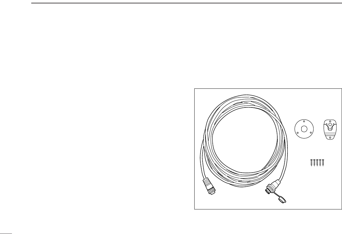
■HM-127 supplied accessories
Accessories included with the HM-127: Qty.
qConnection cable (OPC-1000: 6 m; 20 ft) ...................... 1
wMounting base ................................................................ 1
eMicrophone hanger ........................................................ 1
rScrews (M3 ×16; tapping) ............................................. 5
q
we
r
34
13
HM-127 REMOTE-CONTROL MICROPHONE
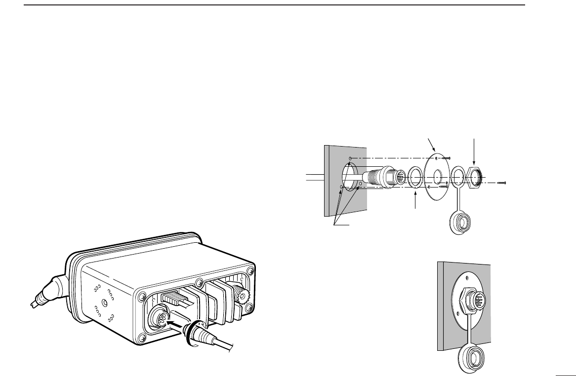
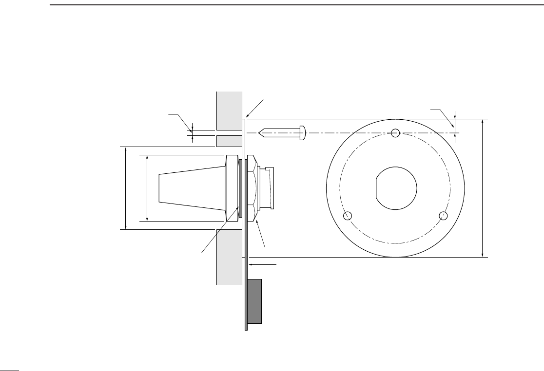
■Installation
The optional HM-127 can be connected to the transceiver di-
rectly, as well as via the supplied connection cable for longer
distance remote operation. The connector of the connection
cable can be installed into a cabinet, wall, etc., as a built-in
plug.
For longer distance remote operation, the optional extension
cable, OPC-999 (6 m; 20 ft/Connecting between transceiver
and the connection cable.), is available, and up to 2 OPC-999
can be added.
qInsert the supplied cable into the external microphone jack
and tighten the cable nut as shown below.
wTo use the supplied cable as a wall socket, follow the fol-
lowing steps.
eUsing the mounting base, carefully mark off the 2 spots
where the cable and screws will be fastened.
rDrill holes at these marks.
tInstall the mounting base using screws as shown below.
yThe installation is finished
when it is completed.
Gasket
Cap
Mounting base Nut
Screw holes
(approx. 2 (d) mm; 3⁄32″)
35
13 HM-127 REMOTE-CONTROL MICROPHONE
50 (d) mm; 131⁄32˝
23 (d) mm; 29⁄32˝
24 to 27 (d) mm
(15⁄16 to 11⁄16˝)
5 mm; 3⁄16˝
Gasket
Mounting base
Cap
Nut
2 mm; 3⁄32˝
36
13
HM-127 REMOTE-CONTROL MICROPHONE
■Channel selection
◊Channel 16
qPush [16] to select Channel 16.
wPush [CH/WX] to return to the
condition before selecting Chan-
nel 16, or push [Y] or [Z] to se-
lect operating channel.
◊Call channel
qPush [16•9] for 1 sec. to select
call channel.
wPush [CH/WX] to return to the
condition before selecting call
channel, or push [Y] or [Z] to se-
lect operating channel.
◊Weather channels
qPush [CH/WX] once or twice to
select weather channel group.
wPush [Y] or [Z] to select weather
channel.
ePush [CH/WX] to return to the
condition before selecting the
weather channel group.
◊U.S.A., International and Canadian
channels
qPush [CH/WX] to select regular channel.
•Push [CH/WX] again, if weather channel appears.
wPush [CH/WX•U/I/C], while pushing [H/L], to select chan-
nel group.
•U.S.A., International and Canadian channels can be selected in
Push
Push for 1 sec.
Push
Push
while pushing
U.S.A. channels
Canadian channelsInternational channels
+
+
37
13 HM-127 REMOTE-CONTROL MICROPHONE
■Receiving and transmitting
qPush [PWR] to turn power ON.
wPush [VOL], then [Y]/[Z] to adjust audio output level.
•Push [SQL], then [Y]/[Z] to mute any audio noise, if necessary.
ePush [Y]/[Z] to select the desired channel.
•When receiving a signal, “ ” appears and audio is emitted
from the speaker.
•Further adjustment of audio level may be necessary at this point.
rPush [H/L] to select the output power, if necessary.
•“LOW” appears when low power is selected.
•Choose low power for shorter, high power for longer distance
communications.
•Some channels are low power only.
tPush and hold [PTT] to transmit, then speak into the mi-
crophone.
•“ ” appears.
•Channel 70 cannot be used for transmission (for GMDSS use).
Simplex channels, 3, 21, 23, 61, 64, 81, 82 and 83 CAN-
NOT be lawfully used by the general public in U.S.A. wa-
ters.
yRelease [PTT] to receive.
IMPORTANT: To maximize the readability of your trans-
mitted signal (voice), pause a few sec. after pushing [PTT],
hold the microphone 10 to 15 cm (4 to 6 inches) from your
mouth and speak at a normal voice level.
•Tri-watch becomes dualwatch when receiving a signal on the call
channel.
w Set volume
w Set squelch,
if required
r Set output power
t Speak into
microphone
q Turn power ON
e Set channel
t Push to
transmit
y Release
to receive
38
13
HM-127 REMOTE-CONTROL MICROPHONE
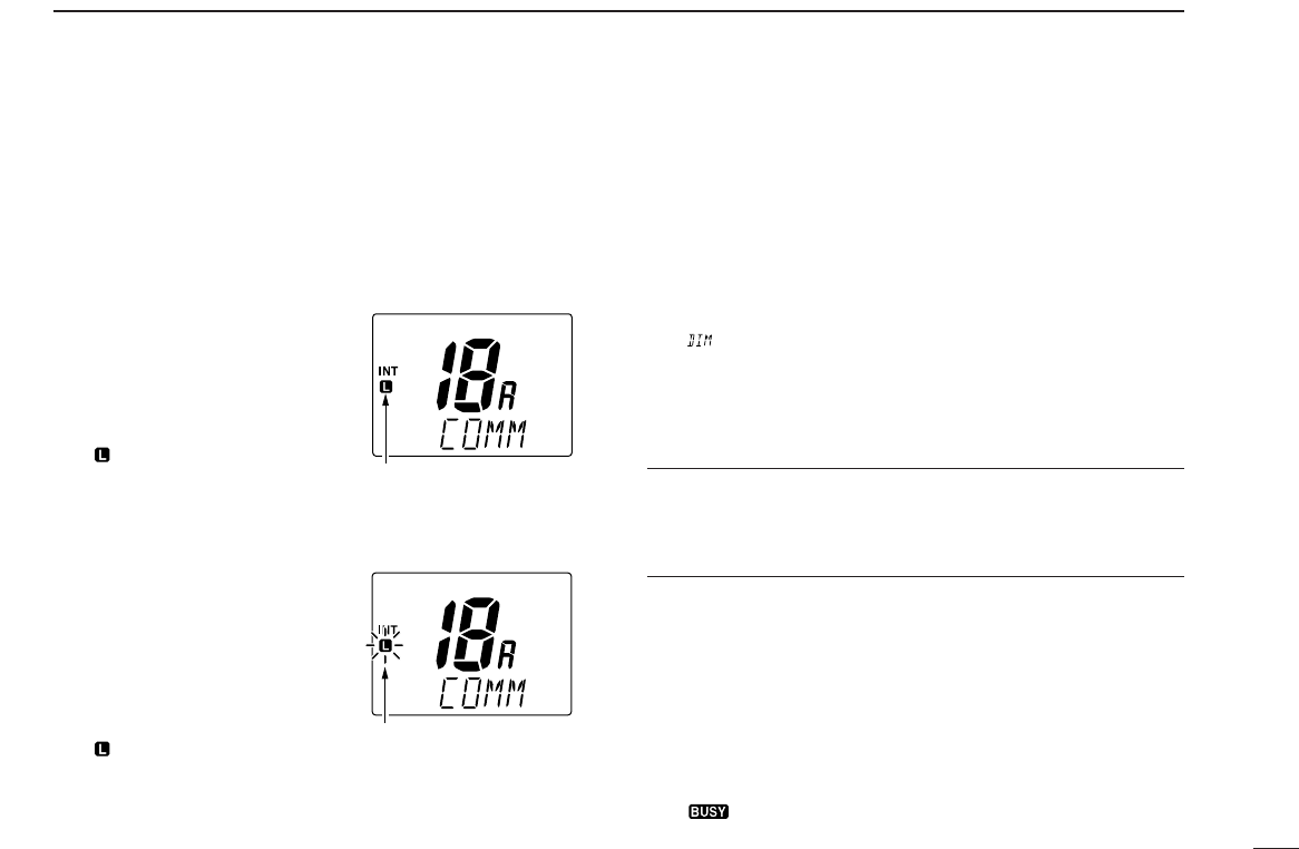
■Lock functions
The lock function electronically locks keys and switches to
prevent accidental changes and function access from the mi-
crophone.
•All keys, switches and controllers on the transceiver are functional.
◊Activating the lock
function
➥Push [SQL] while pushing
[H/L] to turn the lock function
ON and OFF.
•“ ” appears.
•Only [PWR], [PTT], [H/L],
[SQL•MONI], [VOL]+[Y]/[Z] and
[SQL]+[Y]/[Z] are functional.
◊Activating the all key
lock function
➥Turn the power ON by pushing
[PWR] while pushing [H/L] to
turn the all key lock function
ON and OFF.
•“ ” flashes.
•Only [PWR] and [PTT] are functional.
■Display backlighting
The function display and switches can be backlit for better
visibility under low light conditions. And the backlighting con-
dition can be adjusted independently from the transceiver.
qPush [VOL•DIM] for 1 sec. to enter backlight adjusting
mode.
•“ ” with number of backlight level appears in the channel name
indicator.
wPush [Y]/[Z] to adjust the backlight level.
•The backlight level is adjustable between 0 (lights OFF) and 7
(brightest).
For your reference:
Pushing [Y]/[Z], while [H/L] is pushed, also adjusts backlight
level.
•No backlight level indication is available.
■Monitor function
The monitor function releases the noise squelch mute of the
microphone only. (An independent noise squelch system is
employed.)
➥Push [SQL•MONI] for 1 sec. to activate the monitor func-
tion.
•“ ” flashes and audio is emitted.
•Any key, except [Y]/[Z], cancels the monitor function.
Appears when the lock
function is in use.
Flashes when the all lock
function is in use.

39
13 HM-127 REMOTE-CONTROL MICROPHONE
■Call channel programming.
qPush [CH/WX•U/I/C] several times
while pushing [H/L] to select the
desired channel group (USA, INT,
CAN) to be programmed.
wPush [16•9] for 1 sec. to select the
call channel of the selected chan-
nel group.
•“CALL” and call channel number ap-
pear.
ePush [16•9] again for 3 sec. (until
long beep changes to 2 short
beeps) to enter call channel pro-
gramming condition.
•Call channel number and channel
group to be programmed flashes.
rPush [Y]/[Z] to select the desired
channel.
tPush [16•9] to program the dis-
played channel as the call channel.
•The call channel number and channel
group stop flashing.
■Starting a scan
qPush [CH/WX•U/I/C] several times while pushing [H/L] to
select the channel group (USA, INT, CAN), if desired.
•When the weather alert function is in use, select the desired
weather channel with [CH/WX] and [Y]/[Z].
wPush [SCN] to start priority or normal scan.
•“SCAN” appears during normal scan.
•The priority channel readout indicates “16”, and “P” and “SCAN”
indicators appear during priority scan.
•When a signal is received, scan pauses until the signal disap-
pears or resumes after pausing 5 sec. according to set mode set-
ting (Channel 16 is still monitored during priority scan).
•Push [Y]/[Z] to check the scanning tag channels, to change the
scanning direction or resume the scan manually.
eTo stop the scan, push [SCN].
•“SCAN” disappears.
•Pushing [PTT], [16•9] or [CH/WX] also stops the scan.
■Setting tag channels
qPush [CH/WX•U/I/C] several times while pushing [H/L] to
select the channel group (USA, INT, CAN), if desired.
wPush [Y]/[Z] to select the desired channel to set as a tag
channel.
ePush [SCN•TAG] for 1 sec. to set the displayed channel as
a tag channel.
•“ ” appears.

13
HM-127 REMOTE-CONTROL MICROPHONE
40
rTo cancel the tag channel setting, push [SCN•TAG] for
1 sec.
•“ ” disappears.
•Clearing all tag channels in the selected channel group
➥Push [SCN•TAG] while pushing [H/L] for 3 sec. (until long
beep changes to 2 short beeps).
■Dualwatch/Tri-watch operation
qPush [Y]/[Z] to select the desired channel.
•Push [CH/WX•U/I/C] several times while pushing [H/L] to select
the channel group (USA, INT, CAN), if desired.
wPush [CH/WX•DW] for 1 sec. to start dualwatch or tri-
watch.
•“DUAL” appears during dualwatch; “TRI” appears during tri-
watch.
•Beep tone sounds when a signal is received on Channel 16.
•Tri-watch becomes dualwatch when receiving a signal on the call
channel.
eTo cancel dualwatch/tri-watch, push [CH/WX•DW] again.
■Set mode programming
Set mode is used to change the condition of the transceiver’s
functions and the microphone’s own functions:
In this section, instructions are for the microphone’s own func-
tions only. Refer p. 30–33 for the setting of the other func-
tions. (Some functions may not be selected from the micro-
phone.)
◊Entering set mode
qTurn power OFF.
wWhile pushing [16•9], turn power ON.
•After beep emission, a set mode item (in the channel name indi-
cator and condition in the channel number readout) is displayed.
ePush [16•9] to select the desired item, if necessary.
rPush [Y]/[Z] to select the desired condition of the item.
tTurn power OFF, then ON to exit set mode.
•Beep tone “BEEP”
➥Push [Y] to turn ON,
[Z] to turn OFF the beep
output.
•LCD contrast “LCD CONTRAST”
➥Push [Y]/[Z] to adjust
to a suitable LCD contrast.
Push
Push
• •
• •
41
13 HM-127 REMOTE-CONTROL MICROPHONE
■Intercom operation
qPush [LO/DX•IC] for 1 sec. to ac-
tivate the intercom function.
•“IC” appears in the priority channel
readout.
•The channel name disappears.
wPush [PTT] to talk.
•“ ” appears in the channel
name indicator.
eRelease [PTT] to listen.
•“ ” appears in the channel name indicator when the trans-
ceiver is in talking mode.
rPush [LO/DX•IC] to cancel the intercom function.
•Pushing [16], [SCN•TAG] or [CH/WX] is also cancels the inter-
com function.
For your reference:
In case the intercom mode is selected with the transceiver
during microphone power OFF, the microphone power is au-
tomatically turned ON and the intercom mode is selected.
◊Intercom beep function
➥Push [LO/DX•IC] for more than 1 sec.
•Emits intercom beep while holding.
■Channel names
qPush [Y]/[Z] to select a channel to program.
•Push [CH/WX•U/I/C] several times while pushing [H/L] to select
the channel group (USA, INT, CAN), if desired.
wWhile pushing [H/L], push [16•9].
•The 1st character of the currently programmed comment flashes.
ePush [Y]/[Z] to select a character.
rPush [SQL] to move to right; then push [Y]/[Z] to select a
character.
•Push [VOL] to move to the left.
tContinue until the desired characters have been selected,
then push [16•9] to return to normal operation.
•Available characters
(r)
(s) (t) (u) (v) (w) (x) (y) (z)
(q)
(3)
(D)
(N)
(X)
(h)
(+)
(4)
(E)
(O)
(Y)
(i)
(–)
(5)
(F)
(P)
(Z)
(j)
(✱)
(6)
(G)
(Q)
(a)
(k)
(/)
(7)
(H)
(R)
(b)
(l)
(,)
(8)
(I)
(S)
(c)
(m)
(space)
(9)
(T)
(d)
(n)
(0)
(A)
(U)
(e)
(o)
(1)
(B)
(V)
(f)
(p)
(2)
(C)
(J) (K) (L)
(M)
(W)
(g)
(.)
(
))((
)(’)(&)(
%
)($)(#)(")(!)
Appears when the inter-
com function is in use.
42
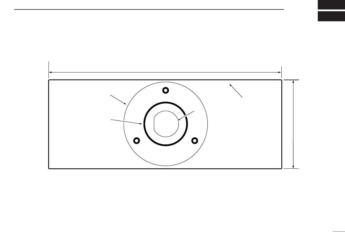
TEMPLATE
139 (515 32 )
53 (2332 )
Unit: mm (inch)
24 to 27 (d) mm
(15 16 to 1116 )
2 mm; 332
MB-69
HM-127

Count on us!
1-1-32 Kamiminami, Hirano-ku, Osaka 547-0003 Japan
A-6019H-1US
Printed in Japan
© 2000 Icom Inc.