ICOM orporated IC-M602 IC-M602 User Manual
ICOM Incorporated IC-M602 Users Manual
UserManual.wiki
>
ICOM orporated
>
IC M602 User Manual
Users Manual
Navigation menu
Upload a User Manual
Namespaces
Wiki Guide
HTML
PDF
Info
Views
User Manual
Discussion / Help
Navigation

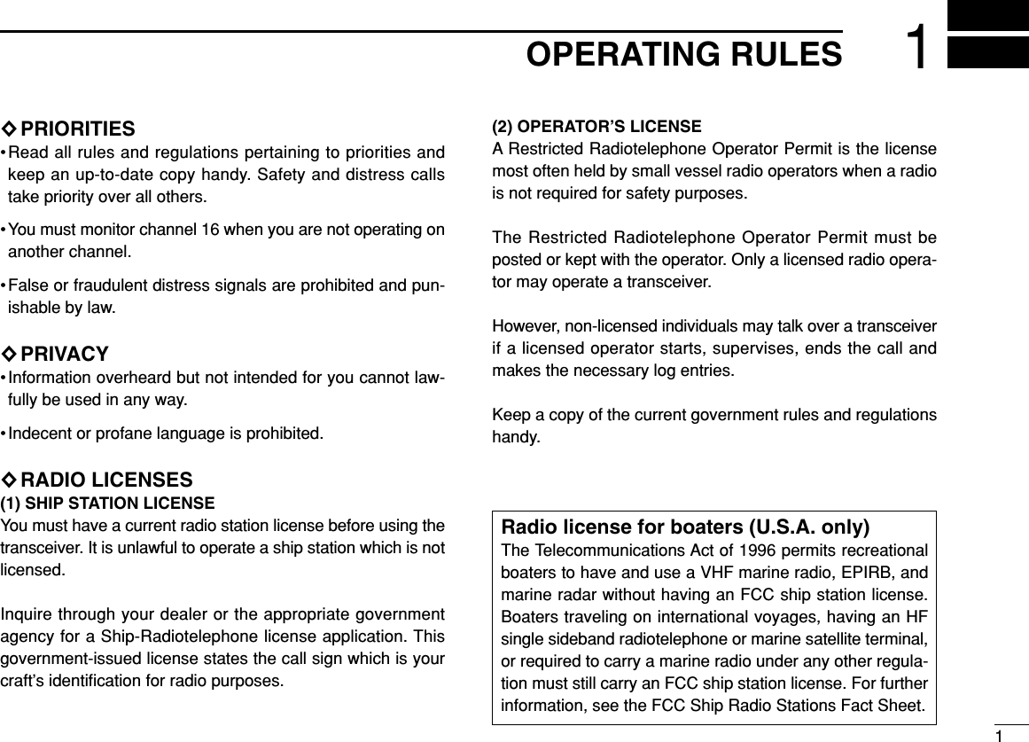
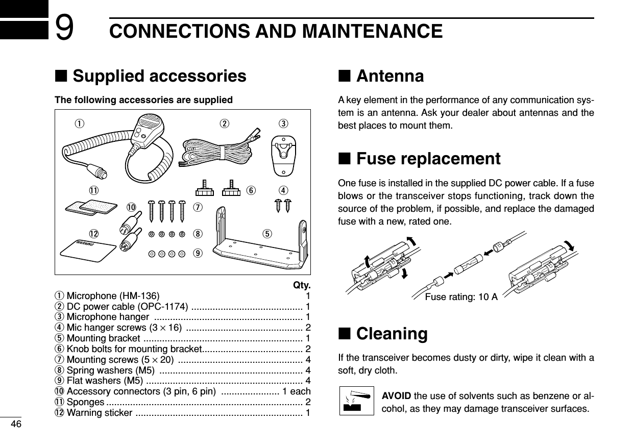
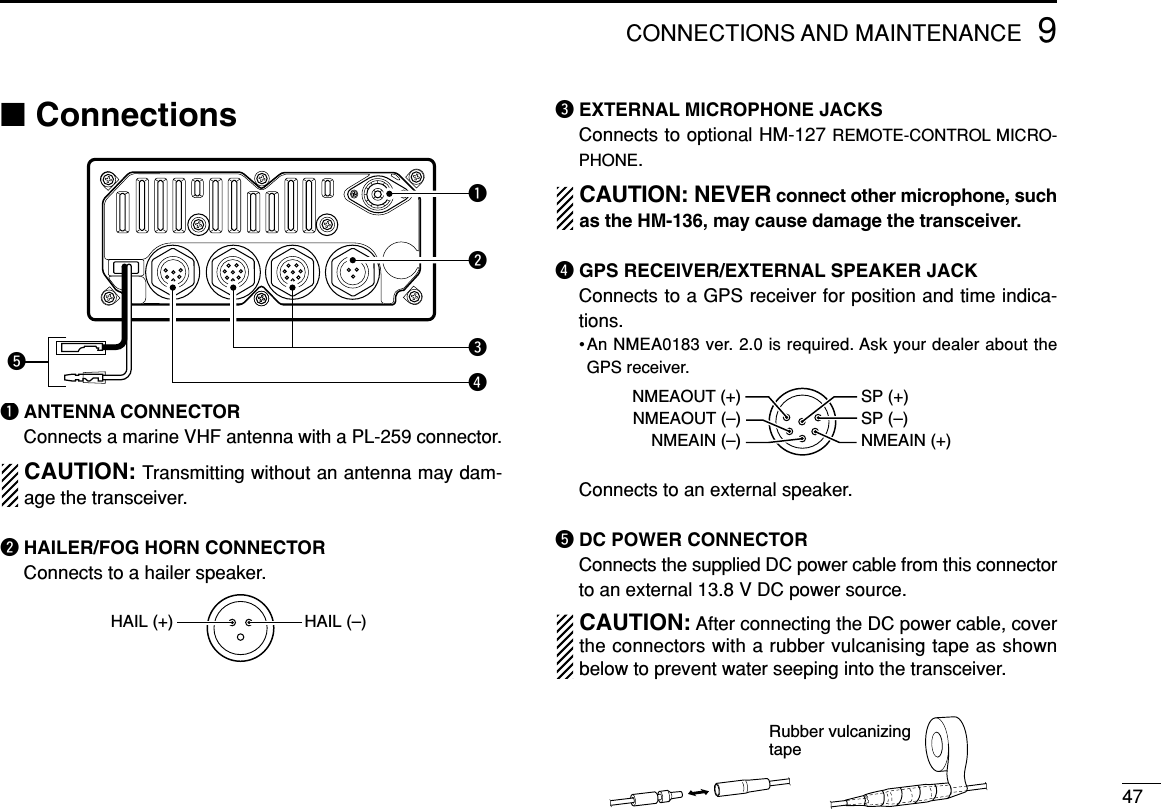
![iiIN CASE OF EMERGENCYIf your vessel requires assistance, contact other vessels andthe Coast Guard by sending a distress call on Ch 16.Or, transmit your distress call using digital selective calling onCh 70.USING CHANNEL 16DISTRESS CALL PROCEDURE1. “MAYDAY MAYDAY MAYDAY.”2. “THIS IS ...............” (name of vessel)3. Your call sign or other indication of the vessel (AND 9-digit DSC ID if you have one).4. “LOCATED AT ...............” (your position)5. The nature of the distress and assistance required.6. Any other information which might facilitate the rescue.USING DIGITAL SELECTIVE CALLING (Ch 70)DISTRESS CALL PROCEDURE1. While lifting up the switch cover, push and hold[DISTRESS] for 5 sec. until you hear 5 short beepschange to one long beep.2. Wait for an acknowledgment from a coast station.• Channel 16 is automatically selected.3. Push and hold [PTT], then transmit the appropriateinformation as at above.WARNING STICKERNOTEA WARNING STICKER is supplied with the transceiver.To comply with FCC regulations, this sticker must be affixed insuch a location as to be readily seen from the operating con-trols of the radio like as follows. Make sure the chosen loca-tion is clean and dry before applying the sticker. (p. 46)EXAMPLE](https://usermanual.wiki/ICOM-orporated/IC-M602/User-Guide-278623-Page-3.png)

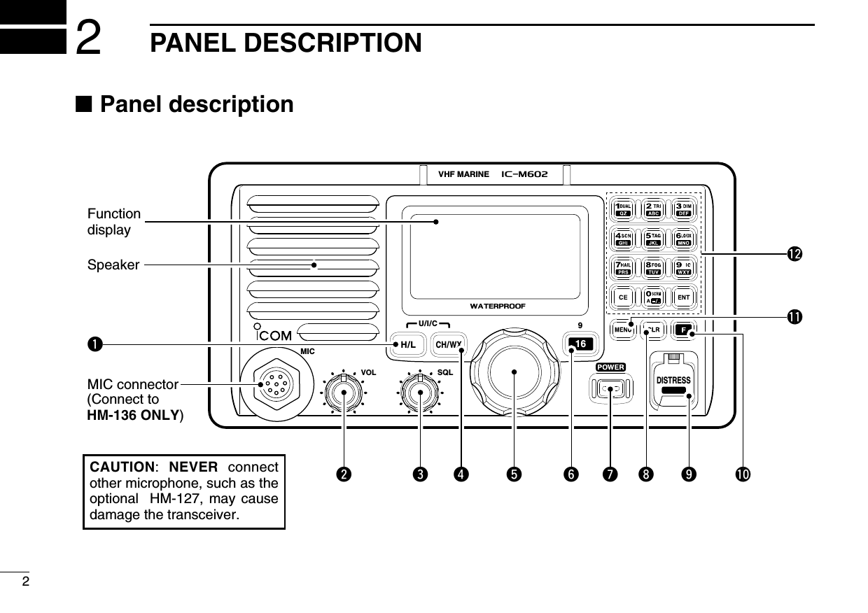
![qTRANSMIT POWER SWITCH [H/L]➥Toggles high or low power when pushed. (p. 10)• Some channels are set to low power only.➥While pushing this switch, some switches perform sec-ondary functions.wVOLUME CONTROL [VOL] (P. 10)Adjusts the audio level.eSQUELCH CONTROL [SQL] (P. 10)Sets the squelch threshold level.rCHANNEL SWITCH [CH/WX•U/I/C] (pgs. 8, 9)➥Selects and toggles the regular channels or weatherchannel when pushed momentarily.➥While pushing [H/L], push to select one of 3 regularchannels in sequence.•International, U.S.A. and Canadian channels are available forregular channels.tCHANNEL SELECTOR [CHANNEL] (p. 10)Rotate [CHANNEL] to select the operating channels, setmode contents, etc.yCHANNEL 16/CALL CHANNEL SWITCH [16•9]➥Selects channel 16 when pushed. (p. 8)➥Selects call channel when pushed for 1 sec. (p. 8)•“CALL” appears when call channel is selected.➥Push for 3 sec. to enter call channel programming con-dition when call channel is selected. (p. 11)➥While pushing [H/L], enters memory name programmingcondition. (p. 11)➥While turning power ON, enters set mode when pushedand held. (p. 42)uPOWER SWITCH [POWER]Push to toggle the transceiver power ON or OFF.iCLEAR SWITCH [CLR]Push to cancel the entered function.oDISTRESS SWITCH [DISTRESS] (p. 18)Transmits distress call when pushed for 5 sec.!0 FUNCTION SWITCH [F]After pushing, activates the secondary functions.•“F” appears when a secondary function can be accessed.!1 DSC MENU SWITCH [MENU] (P. 16)➥Toggles the DSC menu ON or OFF when pushed.PANEL DESCRIPTION32](https://usermanual.wiki/ICOM-orporated/IC-M602/User-Guide-278623-Page-9.png)
![42PANEL DESCRIPTION!2 KEYPAD ➥Inputs numeral “1” for channel number input,etc.➥Inputs “1,” “Q,” “Z,” “q,” “z” or space for chan-nel comment input.➥After pushing [F], turns the dualwatch functionON and OFF. (p. 13)➥Inputs numeral “2” for channel number input,etc.➥Inputs “2,” “A,” “B,” “C” “a,” “b” or “c” for chan-nel comment input.➥After pushing [F], turns the tri-watch functionON and OFF. (p. 13)➥Inputs numeral “3” for channel number input,etc.➥Inputs “3,” “D,” “E,” “F,” “d,” “e” or “f” for chan-nel comment input.➥After pushing [F], push this switch and rotate[CHANNEL] to adjust the brightness of theLCD and switch backlight.➥Inputs numeral “4” for channel number input,etc.➥Inputs “4,” “G,” “H,” “I,” “g,” “h” or “i” for channelcomment input.➥After pushing [F], starts and stops the scanfunction. (p. 15)](https://usermanual.wiki/ICOM-orporated/IC-M602/User-Guide-278623-Page-10.png)
![52PANEL DESCRIPTION➥Inputs numeral “5” for channel number input,etc.➥Inputs “5,” “J,” “K,” “L,” “j,” “k” or “l” for channelcomment input.➥After pushing [F], sets the displayed channelas a tag (scanned) channel.➥While pushing [H/L], push for 3 sec. to clear alltag channels.➥Inputs numeral “6” for channel number input,etc.➥Inputs “6,” “M,” “N,” “O,” “m,” “n” or “o” for chan-nel comment input.➥After pushing [F], turns the attenuator functionON and OFF. (p. 10)•“LOCAL” appears when the attenuator is in use. ➥Inputs numeral “7” for channel number input,etc.➥Inputs “7,” “P,” “R,” “S,” “p,” “r” or “s” for chan-nel comment input.➥After pushing [F], turns the hailer function ONand OFF. (p. 39)➥Inputs numeral “8” for channel number input,etc.➥Inputs “8,” “T,” “U,” “V,” “t,” “u” or “v” for channelcomment input.➥After pushing [F], turns the auto fog horn func-tion ON and OFF. (p. 40)➥Inputs numeral “9” for channel number input,etc.➥Inputs “9,” “W,” “X,” “Y,” “w,” “x” or “y” for chan-nel comment input.➥After pushing [F], turns the intercom functionON and OFF. (p. 38)➥Inputs numeral “0” for channel number input,etc.➥Push for 1 sec. to edit “A” channel for channelnumber input.➥Inputs “0” and symbols (-/.,()*+<=>@) for channel comment input.➥After pushing [F], activates an optional voicescrambler function. (p. 12)•The optional voice scrambler function cannot beused on channel 16 and 70.➥Fixes input of channel number and channelcomment, etc. ➥Clears entered digits and retrieves the previ-ous frequency, channel or channel names dur-ing setting.](https://usermanual.wiki/ICOM-orporated/IC-M602/User-Guide-278623-Page-11.png)
![72PANEL DESCRIPTION■Microphone (HM-136)qPTT SWITCH [PTT] (p. 10)Push and hold to transmit; release to receive.wCHANNEL UP/DOWN SWITCHES [YY]/[ZZ](P. 10)Push either switch to change the operating channel, setmode contents, etc.eCHANNEL 16/CALL CHANNEL SWITCH [16/9]➥Push to select channel 16; push for 1 sec. to channel 9.(p. 8)➥While pushing [16/9], turn power ON to toggle the lockfunction ON and OFF. (p. 9)SpeakerMicrophonewqe16/9iCHANNEL NUMBER READOUT➥Indicates the selected operating channel number. “A” appears when a simplex channel is selected. (p. 9)“b” appears when a receive only channel for a Canadianchannel group is selected.➥“F” appears when [F] switch is pushed.oCALL CHANNEL INDICATOR (p. 8)“CALL” appears when the call channel is selected.!0 CHANNEL GROUP INDICATOR (pgs. 8, 9)Indicates whether an International “INT”, U.S.A. “USA”,Canadian “CAN” or weather “WX” channel is selected.!1 DUPLEX INDICATOR (p. 9)Appears when a duplex channel is selected.!2 POWER INDICATOR (p. 10)➥“25W” appears when high power is selected.➥“1W” appears when low power is selected.!3 TAG CHANNEL INDICATOR (p. 15)Appears when a tag channel is selected.](https://usermanual.wiki/ICOM-orporated/IC-M602/User-Guide-278623-Page-13.png)
![83BASIC OPERATION■Channel selection◊Channel 16Channel 16 is the distress and safety channel. It is used forestablishing initial contact with another station and for emer-gency communications. Channel 16 is monitored during bothdualwatch and tri-watch. While standing by, you must monitorchannel 16.➥Push [16•9] momentarily to select channel 16.➥Push [CH/WX•U/I/C] to return to the condition before se-lecting channel 16, or rotate [CHANNEL] to select operat-ing channel.◊Channel 9 (Call channel)Each regular channel group has a separate leisure-use callchannel. The call channel is monitored during tri-watch. Thecall channels can be programmed (p. 11) and are used tostore your most often used channels in each channel groupfor quick recall.➥Push [16•9] for 1 sec. to select the call channel of the se-lected channel group.•“CALL” and call channel number appear. • Each channel group may have an independent call channel afterchanging a call channel.➥Push [CH/WX•U/I/C] to return to the condition before se-lecting call channel,or rotate [CHANNEL] to select operat-ing channel.Push for1 sec.916BUSY-25W---INT---CALLLOCAL--DUPSCRAM--TAGNORMAL-SCAN-34"34.206N123"23.236W--UTC-10:10--CALLINGPush916BUSY-25W---INT---CALLLOCAL--DUPSCRAM--TAGNORMAL-SCAN-34"34.206N123"23.236W--UTC-10:10--CALLING](https://usermanual.wiki/ICOM-orporated/IC-M602/User-Guide-278623-Page-14.png)
![3BASIC OPERATION9◊U.S.A., Canadian and International channelsThere are 57 U.S.A., 61 Canadian and 57 International chan-nels. These channel groups may be specified for the operat-ing area.qPush [CH/WX•U/I/C] to select a regular channel.• If a weather channel appears, push [CH/WX•U/I/C] again.wWhile pushing [H/L], push [CH/WX•U/I/C] to change thechannel group, if necessary.•U.S.A., International (INT) and Canadian channels can be se-lected in sequence.eRotate the channel selector to select a channel.•“DUP” appears for duplex channels.• “A” appears for simplex channels.◊Weather channelsThere are 10 weather channels. Used for monitoring weatherchannels from the NOAA (National Oceanographic and At-mospheric Administration) broadcasts.The transceiver can detect a weather alert tone on the se-lected weather channel while receiving the channel, duringstandby on a regular channel or while scanning. See“Weather alert” on p. 43.qPush [CH/WX•U/I/C] once or twice to select a weatherchannel.•“WX” appears when a weather channel is selected.• “WX ALERT” appears when the weather alert function is in use.(p. 43)wRotate the channel selector to select a channel.Push onceor twiceWhen weather alert is OFF. When weather alert is ON.WXALERTWXCH/WXPush +U.S.A. channelsH/L CH/WXCanadian channelsCANInternational channelsINTDUPUSA](https://usermanual.wiki/ICOM-orporated/IC-M602/User-Guide-278623-Page-15.png)
![■Receiving and transmittingCAUTION: Transmitting without an antenna may dam-age the transceiver.qPush [POWER] to turn power ON.wSet the audio and squelch levels.➥Rotate [SQL] fully counterclockwise in advance.➥Rotate [VOL] to adjust the audio output level.➥Rotate [SQL] clockwise until the noise disappears.eTo change the channel group, push [CH/WX•U/I/C] whilepushing [H/L]. (pgs. 8, 9)rRotate the channel selector or push [Y]/[Z] on the micro-phone to select the desired channel.• When receiving a signal, “BUSY” appears and audio is emittedfrom the speaker.• Further adjustment of [VOL] may be necessary at this point.• Use the optional voice scrambler function for privacy. (p. 12)tPush [F], then push [6 LO/DX] to turn the receive attenu-ator ON or OFF if necessary.•“LOCAL” appears when the receive attenuator is in use.yPush [H/L] to select the output power if necessary.•“25W” or “1W” appears when high or low power is selected, re-spectively.•Choose low power to conserve power, choose high power forlonger distance communications.• Some channels are for low power only.uPush and hold [PTT] to transmit, then speak into the mi-crophone.•“TX” appears.• Channel 70 cannot be used for transmission.Simplex channels, 3, 21, 23, 61, 64, 81, 82 and 83 CAN-NOT be lawfully used by the general public in U.S.A. wa-ters.iRelease [PTT] to receive.IMPORTANT: To maximize the readability of your trans-mitted signal, pause a few sec. after pushing [PTT], holdthe microphone 1 to 2 inches (2.5 to 5 cm) from yourmouth and speak at a normal voice level.WATERPROOFVOLiM602VHF MARINEMICU/I/C 9SQL16/9wetqrryui3BASIC OPERATION10](https://usermanual.wiki/ICOM-orporated/IC-M602/User-Guide-278623-Page-16.png)
![3BASIC OPERATION11■Call channel programmingThe call channel is used to select channel 9, however, youcan program your most often-used channels in each channelgroup for quick recall.qWhile pushing [H/L], push [CH/WX•U/I/C] once or moretimes to select the desired channel group (U.S.A., Interna-tional, Canada) to be programmed.wPush [16•9] for 1 sec. to select the call channel of the se-lected channel group.•“CALL” and call channel number appear.ePush [16•9] again for 3 sec. (until long beep changes to 2short beeps) to enter callchannel programming con-dition.•Channel number starts blink-ing.rRotate the [CHANNEL] toselect the desired channel.tPush [16•9] to program thedisplayed channel as thecall channel.•Push [CH/WX•U/I/C] to can-cel.•The channel number stopsblinking.■Channel namesMemory channels can be tagged with alphanumeric namesof up to 10 characters each. Capital letters, small letters, numerals, some symbols (! "# $ % & ' ( ) * + ,- ./) and spaces can be used.qSelect the desired memory channel.• Cancel dual watch, tri-watch or scan in advance.wWhile pushing [H/L], push [16•9] to edit memory channelname.•A cursor appears and blinks.ePush keypad several times to enter the desired character.• Rotate [CHANNEL] or push [Y]/[Z] on the microphone for cursormovement.rPush [ENT] to input and set the name.• Push [CLR] to cancel.• The cursor disappears.tRepeat steps qto rto program other memory channelnames, if desired.BUSYBUSY-25W25W------INTINT------CALLCALLLOCAL--DUPLOCAL--DUPSCRAMSCRAM----TAGTAGNORMAL-SCANNORMAL-SCAN-34"34.206N34"34.206N123"23.236W123"23.236W----UTCUTC-10:1010:10----CALLINGCALLINGBUSYBUSY-25W25W------INTINT------CALLCALLLOCAL--LOCAL--DUPDUPSCRAMSCRAM----TAGTAGNORMAL-SCANNORMAL-SCAN-34"34.206N34"34.206N123"23.236W123"23.236W----UTCUTC-10:1010:10------INTLINTLBUSY-BUSY-25W25W------INTINT------CALLCALLLOCAL--LOCAL--DUPDUPSCRAMSCRAM----TAGTAGNORMAL-SCANNORMAL-SCAN-34"34.206N34"34.206N123"23.236W123"23.236W----UTCUTC-10:1010:10-PLEASURELEASURE](https://usermanual.wiki/ICOM-orporated/IC-M602/User-Guide-278623-Page-17.png)
![3BASIC OPERATION12■Optional voice scrambler operation◊Activating the scramblerThe optional voice scrambler provides private communica-tions. In order to receive or send scrambled transmissionsyou must first activate the scrambler function. To activate thefunction, an optional UT-112 is necessary. See p. 45 for set-ting the scrambler unit. Ask your dealer for details.The scrambler function automatically turns OFF whenchannel 16 or 70 is selected.qSelect an operating channel other than channel 16 and 70.wPush [F] then [0 SCRM] to toggle an optional scramblerfunction ON or OFF.• “SCRAM” appears.eTo turn the scrambler function OFF, repeat step w.• “SCRAM” disappears.◊Programming scrambler codesThere are 32 codes (1 to 32) available for programming whenthe optional UT-112 is installed. In order to understand oneanother, all transceivers in your group must have the samescramble code. This function may not be available depend-ing on dealer setting.qTurn power OFF.wWhile pushing [16•9], turn power ON to enter set mode.eAfter the display appears, release [16•9].rRotate [CHANNEL] to select the “Scrambler Code,”push [ENT].tRotate [CHANNEL] to select desired scrambler code.yPush [ENT] to set and exit the scrambler code item.uRotare [CANNEL] to select “Exit,” then push [ENT] toexit set mode.Enter set modePOWER+916ENT ENTSelect itemthen pushSelect codethen pushScrambler Code˘9˘7--Set Mode--˘5˘6˘8˘<ENT˘OK>˘Scan Type˘Scan Timer--Set Mode--˘Internal Speaker˘Contrast˘Beep˘Dual/Tri COMMANDMIC˘WX Alert˘Internal Speaker˘Contrast--Set Mode--˘Scrambler Code˘Exit˘Scrambler Type˘Foghorn Frequency˘RF Attenuator[Example]: Programming scrambler code 8.](https://usermanual.wiki/ICOM-orporated/IC-M602/User-Guide-278623-Page-18.png)
![■DescriptionDualwatch monitors channel 16 while you are receiving an-other channel; tri-watch monitors channel 16 and the callchannel while receiving another channel.■OperationqSelect the desired operating channel.wPush [F] then [1 DUAL] to start dualwatch or [2 TRI] tostart tri-watch.•“DUAL” appears during dualwatch; “TRI” appears during tri-watch.• Beep tone sounds when a signal is received on channel 16.eTo cancel dualwatch/tri-watch, push [CLR].[Example]: Operating tri-watch on INT channel 25.DUALWATCH/TRI-WATCH SIMULATION•If a signal is received on channel 16, dualwatch/tri-watch pauseson channel 16 until the signal disappears.•If a signal is received on the call channel during tri-watch, tri-watch becomes dualwatch until the signal disappears.•To transmit on the selected channel during dualwatch/tri-watch,push and hold [PTT].Call channelDualwatch Tri-watchDUAL WATCH/TRI-WATCH 413BUSY-25W---INT---CALLLOCAL--DUPSCRAM--TAGTRIMAL-SC16-34"34.206N123"23.236W--UTC-10:10-TELEPHONEBUSY-25W---INT---CALLLOCAL--DUPSCRAM--TAGTRIMAL-SC16-34"34.206N123"23.236W--UTC-10:10-TELEPHONEBUSY-25W---INT---CALLLOCAL--DUPSCRAM--TAGTRIMAL-SC16-34"34.206N123"23.236W--UTC-10:10-TELEPHONEBUSY-25W---INT---CALLLOCAL--DUPSCRAM--TAGTRIMAL-SC16-34"34.206N123"23.236W--UTC-10:10--CALLINGTri-watch starts.Signal is received on call channel.Signal received on channel 16 takes priority.Tri-watch resumes after the signal disappears.](https://usermanual.wiki/ICOM-orporated/IC-M602/User-Guide-278623-Page-19.png)
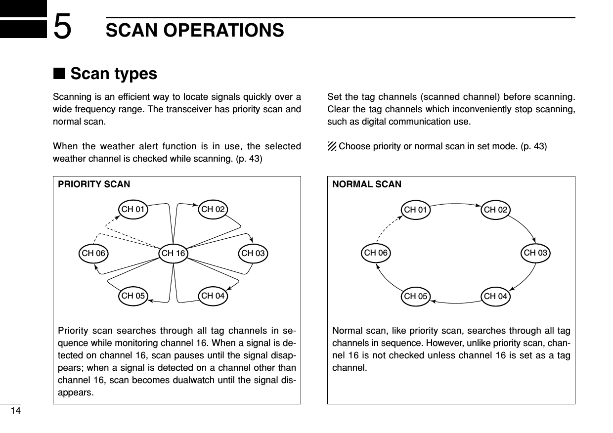
![5SCAN OPERATION15PushSCNGHIthenScan starts. When a signal is receivedBUSY-25W---INT---CALLLOCAL--DUPSCRAM--TAGNORMAL-SCAN-34"34.206N123"23.236W--UTC-10:10---INTL-BUSY-25W---INT---CALLLOCAL--DUPSCRAM--TAGNORMAL-SCAN-34"34.206N123"23.236W--UTC-10:10---INTL-4BUSY-25W---INT---CALLLOCAL--DUPSCRAM--TAGNORMAL-SCAN-34"34.206N123"23.236W--UTC-10:10---INTL-[Example]: Starting a normal scan.■Setting tag channelsFor more efficient scanning, add desired channels as tagchannels or clear tag channels for unwanted channels. Chan-nels set as non-tag channels will be skipped during scanning.Tag channels can be assigned to each channel group(U.S.A., International, Canada) independently.qWhile pushing [H/L], push [CH/WX•U/I/C] once or moretimes to select the desired channel group, if desired.wSelect the desired channel to set as a tag channel.ePush [F] then [5 TAG] to set the displayed channel as atag channel.•“TAG” appears in the function display.rTo cancel the tag channel setting, repeat e.•“TAG” disappears.•Clearing all tag channels in the selected channel group➥While pushing [H/L], push [5 TAG] for 3 sec. to clear all tagchannels in the channel group.■Starting a scanSet scan type (priority or normal scan) and scan resume timerin advance using set mode. (p. 43)qSet tag channels as described at left.wMake sure the squelch is closed to start a scan.eWhile pushing [H/L], push [CH/WX•U/I/C] once or moretimes to select the desired channel group, if desired.rPush [F] then [4 SCN] to start priority or normal scan.•“PRI-SCAN 16” or “NORMAL SCAN” appears in the functiondisplay.•When a signal is detected, scan pauses until the signal disap-pears or resumes after pausing 5 sec. according to set mode set-ting. (Channel 16 is still monitored during priority scan.)• Rotate the [CHANNEL] to check the scanning tag channels, tochange the scanning direction or resume the scan manually.• “16” blinks and a beep tone sounds when a signal is received onchannel 16 during priority scan.tTo stop the scan, push [CLR].](https://usermanual.wiki/ICOM-orporated/IC-M602/User-Guide-278623-Page-21.png)
![166DSC OPERATION■MMSI code programmingThe 9-digit MMSI (Maritime Mobile Service Identity: DSC selfID) code can be programmed at power ON.This code programming can be performed only twice.qTurn power OFF.wWhile pushing [MENU], turn power ON to enter MMSIcode programming condition.eAfter the display appears, release [MENU].rPush [MENU] to enter the DSC menu.tRotate [CHANNEL] to select “Set up,” push [ENT].yRotate [CHANNEL] to select “MMSI check,” push [ENT].uEdit the specific MMSI code directly with keypad.• Rotate [CHANNEL] to move the cursor backward or advance.iInput 9 digit code, then push [ENT] to set the code.• Return to DSC set up menu.oRotate [CHANNEL] to select “Exit,” push [ENT].• Return to DSC menu.• Repeat again to return the normal operation condition.■Position and time programmingA distress call should include the ship’s position and time. Ifno GPS is connected, your position and UTC (Universal TimeCoordinated) time should be input. They are included auto-matically when a GPS receiver (NMEA0183 ver. 2.0) is con-nected. This manual programing is not available when a GPS re-ceiver (NMEA0183 ver. 2.0) is connected.qPush [MENU] to enter the DSC menu.wRotate [CHANNEL] to select “Position Input,” push[ENT].eEdit the digit of your latitude data directly with keypad.• Push [6•MNO] to edit N; north latitude or [7•PRS] to edit S; southlatitude.• Rotate [CHANNEL] to move the cursor backward or advance.• Push [CE] to clear the position data.Input PositionLatitudeLongitude--DSC Menu--<CE˘Null Data>___°__.___W˘˘˘˘˘˘˘˘Null˘_°__.___N˘˘˘˘˘˘˘˘Null<CLR˘Exit / ENT˘OK>MMSI Check˘ä________________--DSC Menu--<CLR˘Exit / ENT˘OK>](https://usermanual.wiki/ICOM-orporated/IC-M602/User-Guide-278623-Page-22.png)
![176DSC OPERATIONrEdit the digit of your longitude data directly with keypad.• Push [3•DEF] to edit E; east longitude or [9•WXY] to edit W; westlongitude.• Rotate [CHANNEL] to move the cursor backward or advance.• Push [CE] to clear the position data.5t Push [ENT] to set the position and advance to time settingcondition.• Push [CLR] to abandon the setting and exit the condition.yEdit the digit of current UTC time directly with keypad.• Rotate [CHANNEL] to move the cursor backward or advance.• Push [CE] to clear the time.uPush [ENT] to set the time.• Push [CLR] to abandon the setting and exit the condition.■Position indicationWhen a GPS receiver (NMEA0183 ver. 2.0) is connected, thetransceiver displays the current position and time. When noGPS receiver is connected, the transceiver displays the man-ually entered position and time.A GPS receiver appropriate for the IC-M602 is not suppliedfrom Icom. An NMEA0183 ver. 2.0 is required for position in-dication. Ask your dealer about the GPS receiver.BUSY-25W---INT---CALLLOCAL--DUPSCRAM--TAGNORMAL-SCAN-34"34.506N123"23.236W--UTC-19:10--CALLINGInput UTC time˘__:__˘˘˘˘˘˘˘˘˘˘˘˘Null--DSC Menu--<CE˘Null Data><CLR˘Exit / ENT˘OK>](https://usermanual.wiki/ICOM-orporated/IC-M602/User-Guide-278623-Page-23.png)
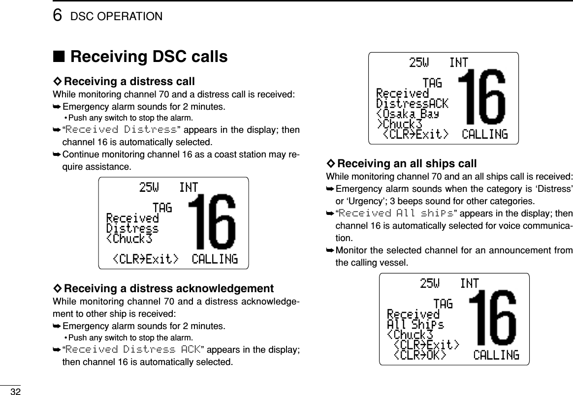
![186DSC OPERATION■Distress callA distress call should be transmitted, if in the opinion of theMaster, the ship or a person is in distress and requires imme-diate assistance.NEVER USE THE DISTRESS CALL WHENYOUR SHIP IS NOT IN AN EMERGENCY. ADISTRESS CALL CAN BE USED ONLY WHENIMMEDIATE HELP IS NEEDED.qConfirm any distress call is not being received.wWhile lifting up the switch cover, push the [DISTRESS] for5 sec. to transmit the distress call.• An emergency channel (Ch 70) is automatically selected and thedistress call is transmitted.• When no GPS is connected, input your position and UTC time, ifpossible.eAfter transmitting the call, the transceiver waits for an ac-knowledgment call on Ch70.•The distress call is automatically transmitted every 3.5 to 4.5minutes.rAfter 5 sec. the every ditress call, the transceiver is set tothe phone frequency (ch 16) automatically.BUSY-25W---INT---CALLLOCAL--DUPSCRAM--TAGNORMAL-SCANWait ACK-34"34.506N<CLR˘Cancel ACK---CALLINGDistress CallTX CompleateNow Wating for ACK<CLR˘Cancel ACK>Distress CallPush for 5 sec.](https://usermanual.wiki/ICOM-orporated/IC-M602/User-Guide-278623-Page-24.png)
![196DSC OPERATIONtWhen receiving the acknowledgment, reply to the con-nected station via the microphone.➥Distress alert contains (default);• Kinds of distress : Undesignated distress• Position data : GPS or manual input position data held for23.5 hrs.➥The distress call is repeated every 3.5–4.5 min., until re-ceiving an ‘acknowledgement.’➥Push [DISTRESS] to transmit a renewed distress call, ifdesired.➥Push [CLR] to cancel the ‘Call repeat’ mode.➥“??” may blink instead of position and time indications,when the GPS data is invalid, or 4 hours after the timedata is input manually.BUSY-25W---INT---CALLLOCAL--DUPSCRAM--TAGReceivedCANDistressACK<Osaka Bay>Chuck3-<CLR˘Exit>--CALLING](https://usermanual.wiki/ICOM-orporated/IC-M602/User-Guide-278623-Page-25.png)
![206DSC OPERATION■Transmitting DSC calls◊Transmitting individual callThe individual call function allows you to transmit a DSC sig-nal to a specific ship only.qPush [MENU] to enter the DSC menu.wRotate [CHANNEL] to select “Individual Call,”push [ENT].eRotate [CHANNEL] to select the desired pre-programmedindividual address or “Manual Input,” push [ENT].• The ID code for the individual call can be set in advance. (p. 29)• When “Manual Input” is selected, set the 9-digit ID code forthe individual you wish to call with keypad.rRotate [CHANNEL] to select a desired intership channelor “Manual Input,” push [ENT].• When “Manual Input” is selected, rotate [CHANNEL] to se-lect desired channel other than channel 70.Select Intership CH<CLR˘Exit / ENT˘OK>˘08˘77--DSC Menu--˘˘06˘69Select Address<CLR˘Exit / ENT˘OK>˘Manual Input˘Margurite--DSC Menu--˘Ricky˘JohnSelect item˘Received Calls˘Individual Call˘All Ships Call--DSC Menu--˘Polling Request˘Position Request˘Group Call](https://usermanual.wiki/ICOM-orporated/IC-M602/User-Guide-278623-Page-26.png)
![216DSC OPERATIONtPush [ENT] to transmit the individual call.• If channel 70 is busy, the transceiver is standby until the channelbecomes clear.yStandby on channel 70 until an acknowledgement is re-ceived.uWhen the acknowledgement is received, the displaychanges to the previously selected channel with beeps.iPush and hold [PTT] to communicate your message to theresponding ship.◊Transmitting individual acknowledgementTransmit an acknowledgement (‘able to comply’ or ‘unable tocomply’) when an individual call for you is received.qPush [MENU] to enter the DSC menu.wRotate [CHANNEL] to select “Individual ACK,” push[ENT].•“Individual ACK” item appears after an individual call isreceived.eRotate [CHANNEL] to select the desired individual addressor ID code, push [ENT].Select Address<CLR˘Exit / ENT˘OK>˘Manual Input˘Margurite--DSC Menu--˘Ricky˘JohnSelect item˘Polling Request˘Individual Call˘Group Call--DSC Menu--˘Position Request˘All Ships Call˘Individual ACKIndividual Call<CLR˘Exit>TX CompleteNow Waiting for ACK--DSC Menu--˘˘Ricky˘IcomIndividual Call Ready<CLR˘Exit / ENT˘OK>--DSC Menu--Individual CallCH70 BUSY<CLR˘Exit>--DSC Menu--Push [ENT] to transmit DSC call. When Ch70 is busy.](https://usermanual.wiki/ICOM-orporated/IC-M602/User-Guide-278623-Page-27.png)
![226DSC OPERATIONrRotate [CHANNEL] to select an acknowledgement “Ableto Comply” or “Unable to Comply,” push [ENT].tIf you select “Unable to Comply,” select the reasonby rotating [CHANNEL], push [ENT].• ‘No reason given,’ ‘Congestion,’ ‘Busy,’ ‘Queue indication,’ ‘Sta-tion Barred,’ ‘No operator,’ ‘Operator Unavailable,’ ‘EquipmentDisable,’ ‘Channel Unable’ and ‘Mode Unable’ are available.yPush [ENT] to transmit the acknowledgement to the se-lected station.uAfter the individual acknowledgement has been transmit-ted, the following indication is displayed.iThen the display change to the channel specified by thecalling station automatically.Individual ACKTX Complete--DSC Menu--Individual ACK Ready<CLR˘Exit / ENT˘OK>--DSC Menu--Select Reason˘No Reason Given˘Busy--DSC Menu--˘˘Queue Indication˘Station Barred˘Channel Unable˘No Operator˘Operator Unavailable˘Equipment Disable<CLR˘Exit / ENT˘OK>˘Mode Unable˘Equipment Disable˘CongestionSelect Action<CLR˘Exit / ENT˘OK>˘Able to Comply˘77--DSC Menu--˘˘06˘Unable to Comply](https://usermanual.wiki/ICOM-orporated/IC-M602/User-Guide-278623-Page-28.png)
![236DSC OPERATION◊Transmitting group callThe Group call function allows you to transmit a DSC signalto a specific group only.qPush [MENU] to enter the DSC menu.wRotate [CHANNEL] to select “Group Call,” push[ENT].eRotate [CHANNEL] to select the desired pre-programmedgroup address or “Manual Input,” push [ENT].• The ID code for the group call can be set in advance. (p. 31)• When “Manual Input” is selected, set the 8-digit ID code forthe group you wish to call with keypad.rRotate [CHANNEL] to select a desired intership channelor “Manual Input,” push [ENT].• When “Manual Input” is selected, rotate [CHANNEL] to se-lect desired channel other than channel 70.tPush [ENT] to transmit the group call.• If channel 70 is busy, the transceiver stands by until the channelbecomes clear.yAfter the group call has been transmitted, the following in-dication is displayed.uPush [CLR] to exit the condition.Group CallTX Complete<CLR˘Exit>--DSC Menu--Group Call ready<CLR˘Exit / ENT˘OK>--DSC Menu--Select Address<CLR˘Exit / ENT˘OK>˘Manual Input˘Osaka--DSC Menu--˘˘Tokyo˘I-comSelect item˘Received Calls˘Individual Call˘All Ships Call--DSC Menu--˘Polling Request˘Position Request˘Group Call](https://usermanual.wiki/ICOM-orporated/IC-M602/User-Guide-278623-Page-29.png)
![246DSC OPERATION◊Transmitting all ships callLarge ships use channel 70 as their ‘listening channel.’ Whenyou want to announce a message to these ships, use the ‘allships call’ function.qPush [MENU] to enter the DSC menu.wRotate [CHANNEL] to select “All Ships Call,” push[ENT].eRotate [CHANNEL] to select the desired category, push[ENT].• Output power of ‘Routine’ category is 1 W (low power) only.rPush [ENT] to transmit the all ships call.• Channel 70 is selected and the all ships call is transmitted.tAfter the all ships call has been transmitted, the followingindication is displayed.yPush [CLR] to exit the condition.All Ships CallTX Complete<CLR˘Exit>--DSC Menu--All Ships Call Ready<CLR˘Exit / ENT˘OK>--DSC Menu--Select Category˘Received Calls˘Routine˘Urgency--DSC Menu--˘Polling Request˘Position Request˘SafetySelect item˘Received Calls˘Individual Call˘All Ships Call--DSC Menu--˘Polling Request˘Position Request˘Group Call](https://usermanual.wiki/ICOM-orporated/IC-M602/User-Guide-278623-Page-30.png)
![256DSC OPERATION◊Transmitting position request callTransmit a position request call when you want to know spe-cific ship’s current position, etc.qPush [MENU] to enter the DSC menu.wRotate [CHANNEL] to select “Position Request,”push [ENT].eRotate [CHANNEL] to select the desired pre-programmedindividual address or “Manual Input,” push [ENT].• The ID code for the individual call can be set in advance. (p. 29)• When “Manual Input” is selected, set the 9-digit ID code forthe individual you wish to call with keypad.rPush [ENT] to transmit the position request call.tAfter the position request call has been transmitted, the fol-lowing indication is displayed.yPush [CLR] to exit the condition.•Even [CLR] hasn’t been pushed, the display automatically re-turns to the original indication after 5 sec. inactivity.Position RequestTX Complete--DSC Menu--˘<CLR˘Exit>Now Waiting for ACKPosition Request Ready<CLR˘Exit / ENT˘OK>--DSC Menu--Select Address<CLR˘Exit / ENT˘OK>˘Manual Input˘Margurite--DSC Menu--˘Ricky˘JohnSelect item˘Received Calls˘Individual Call˘All Ships Call--DSC Menu--˘Polling Request˘Position Request˘Group Call](https://usermanual.wiki/ICOM-orporated/IC-M602/User-Guide-278623-Page-31.png)
![266DSC OPERATION◊Transmitting position reply callTransmit a position reply call when a position request call isreceived.qWhen a position request call is received, the following in-dication is displayed.wPush [ENT] to reply the position request call; push [CLR] toignore the position request call.◊Transmitting polling request callTransmit a polling request call when you want to know spe-cific ship is in communicable area, etc.qPush [MENU] to enter the DSC menu.wRotate [CHANNEL] to select “Polling Request,”push [ENT].eRotate [CHANNEL] to select the desired pre-pro-grammed individual address or “Manual Input,”push [ENT].• The ID code for the individual call can be set in advance. (p. 29)• When “Manual Input” is selected, set the 9-digit ID code forthe individual you wish to call with keypad.Select Address<CLR˘Exit / ENT˘OK>˘Manual Input˘Margurite--DSC Menu--˘Ricky˘JohnSelect item˘Received Calls˘Individual Call˘All Ships Call--DSC Menu--˘Polling Request˘Position Request˘Group CallBUSY-25W---INT---CALLLOCAL--DUPSCRAM--TAGReceivedCANPOS REQ<Chuck3<CLR˘Exit><ENT˘Reply>COMMERCIAL](https://usermanual.wiki/ICOM-orporated/IC-M602/User-Guide-278623-Page-32.png)
![276DSC OPERATIONrPush [ENT] to transmit the polling request call.tAfter the polling request call has been transmitted, the fol-lowing indication is displayedyPush [CLR] to exit the condition.•Even [CLR] hasn’t been pushed, the display automatically re-turns to the original indication after 5 sec. inactivity.◊Transmitting polling reply callTransmit a polling reply call when a polling request call is re-ceived.qWhen a polling request call is received, the following indi-cation is displayed.wPush [ENT] to reply the polling request call; push [CLR] toignore the polling request call.BUSY-25W---INT---CALLLOCAL--DUPSCRAM--TAGReceivedCANPOLL REQ<Chuck3<CLR˘Exit><ENT˘Reply>COMMERCIAL˘Polling RequestTX Complete--DSC Menu--<CLR˘Exit>Now Waiting for ACKPoslling Request Ready˘<CLR˘Exit / ENT˘OK>--DSC Menu--](https://usermanual.wiki/ICOM-orporated/IC-M602/User-Guide-278623-Page-33.png)
![286DSC OPERATION■Setting the distress informationThe nature of the distress call should be included in the dis-tress call.qPush [MENU] to enter the DSC menu.wRotate [CHANNEL] to select “Distress Setting,”push [ENT].eRotate [CHANNEL] to select the nature of the distress,push [ENT].•‘Undesigned,’ ‘Explosion,’ ‘Flooding,’ ‘Collision,’ ‘Grounding,’‘Capsizing,’ ‘Sinking,’ ‘Adrift (Disable adrift),’ ‘Abandoning (Aban-doning ship),’ ‘Piracy (Piracy attack),’ ‘MOB (Man overboard)’ and‘EPIRB (EPIRB emission)’ are available.rThe position information appears. Set the current position,then push [ENT].• Edit the digit of your position data directly with keypad.• Push [6•MNO] to edit N; north latitude or [7•PRS] to edit S; southlatitude.• Push [3•DEF] to edit E; east longitude or [9•WXY] to edit W; westlongitude.• Rotate [CHANNEL] to move the cursor backward or advance.• Push [CE] to clear the position data.Select Nature˘Undesignated˘Flooding--DSC Menu--˘˘Collision˘Grounding˘Abandoning˘Capsizing˘Sinking˘Adrift<CLR˘Exit / ENT˘OK>˘Piracy˘EPIRB˘MOB˘-----˘ExplosionSelect item˘Exit˘Position Request˘Received Calls--DSC Menu--˘Set up˘Distress Setting˘Polling Request](https://usermanual.wiki/ICOM-orporated/IC-M602/User-Guide-278623-Page-34.png)
![296DSC OPERATIONtThe time information appears. Set the current UTC time,push [ENT].• Edit the digit of current UTC time directly with keypad.• Push [CLR] to abandon the setting and exit the condition.• Rotate [CHANNEL] to move the cursor backward or advance.• Push [CE] to clear the time.yPush [ENT] to set the time.• Push [CLR] to abandon the setting and exit the condition.• The selected nature of the distress is stored for 10 minutes.uPush [DISTRESS] for 5 sec. to transmit the distress call.■DSC individual IDA total of 100 DSC address IDs can be programmed andnamed with up to 10 characters.◊Programming address IDqPush [MENU] to enter the DSC menu.wRotate [CHANNEL] to select “Set up,” push [ENT].eRotate the channel selector to select “Add: INDV ID,”push [ENT].Set up˘MMSI Check˘Add:INDV ID˘DEL:INDV ID--DSC Menu--˘Offset time˘DEL:Group ID˘Add:Group IDSelect item˘Exit˘Position Request˘Received Calls--DSC Menu--˘Set up˘Distress Setting˘Polling RequestInput UTC time˘__:__˘˘˘˘˘˘˘˘˘˘˘˘Null--DSC Menu--<CE˘Null Data><CLR˘Exit / ENT˘OK>Input PositionLatitudeLongitude--DSC Menu--<CE˘Null Data>___°__.___W˘˘˘˘˘˘˘˘Null˘_°__.___N˘˘˘˘˘˘˘˘Null<CLR˘Exit / ENT˘OK>](https://usermanual.wiki/ICOM-orporated/IC-M602/User-Guide-278623-Page-35.png)
![306DSC OPERATIONrSet the individual ID and ID name.• Edit the 9-digits of distress ID directly with keypad.• Push keypad several times to edit the character.• Rotate [CHANNEL] to move the cursor backward or advance.• Push [CE] to clear the ID and name.• Push [CLR] to cancel and exit the condition.tPush [ENT] to program and exit the condition.◊Deleting address IDqPush [MENU] to enter the DSC menu.wRotate [CHANNEL] to select “Set up,” push [ENT].eRotate [CHANNEL] to select “DEL: INDV ID,” push[ENT].•When no address ID is programmed, the transceiver exits thecondition automatically.rRotate [CHANNEL] to select the desired ID name for delet-ing.tPush [ENT] to delete the address ID and exit the condition.Select ID<CLR˘Exit / ENT˘OK>˘Turtle˘Margurite--DSC Menu--˘˘Ricky˘JohnSet up˘MMSI Check˘Add:INDV ID˘DEL:INDV ID--DSC Menu--˘Offset time˘DEL:Group ID˘Add:Group IDAdd:Individual IDInput 9 digitsInput name--DSC Menu--˘__________________˘ä________________](https://usermanual.wiki/ICOM-orporated/IC-M602/User-Guide-278623-Page-36.png)
![316DSC OPERATION◊Programming group IDqPush [MENU] to enter the DSC menu.wRotate [CHANNEL] to select “Set up,” push [ENT].eRotate the channel selector to select “Add: GroupID,” push [ENT].rSet the group ID and ID name.• Edit the 8-digits of group ID directly with keypad.• Push keypad several times to edit the character.• Rotate [CHANNEL] to move the cursor backward or advance.• Push [CE] to clear the ID and name.• Push [CLR] to cancel and exit the condition.tPush [ENT] to program and exit the condition.◊Deleting group IDqPush [MENU] to select the DSC menu.wRotate [CHANNEL] to select “Set up,” push [ENT].eRotate [CHANNEL] to select ‘DEL: Group ID,’ push [ENT].• When no group ID is programmed, the transceiver exits the con-dition automatically.rRotate [CHANNEL] to select the desired ID name for delet-ing.tPush [ENT] to delete the group ID and exit the condition.Set up˘MMSI Check˘Add:INDV ID˘DEL:INDV ID--DSC Menu--˘Offset time˘DEL:Group ID˘Add:Group IDAdd:Individual IDInput 8 digitsInput name--DSC Menu--˘__________________˘0ä______________Set up˘MMSI Check˘Add:INDV ID˘DEL:INDV ID--DSC Menu--˘Offset time˘DEL:Group ID˘Add:Group IDSelect item˘Exit˘Position Request˘Received Calls--DSC Menu--˘Set up˘Distress Setting˘Polling Request](https://usermanual.wiki/ICOM-orporated/IC-M602/User-Guide-278623-Page-37.png)
![336DSC OPERATION◊Receiving an individual callWhile monitoring channel 70 and an individual call is re-ceived:➥Emergency alarm or beeps sound depending on the re-ceived category.➥“Received Individual” appears in the display.➥Push [ENT] to change to the channel specified by the call-ing station for voice communication; push [CLR] to ignorethe individual call.◊Receiving a position request callWhile monitoring channel 70 and a position request call is re-ceived:➥“Received POS REQ” appears in the display.➥Push [ENT] to reply to the call.◊Receiving a polling request callWhile monitoring channel 70 and a polling request call is re-ceived:➥“Received POLL REQ” appears in the display.➥Push [ENT] to reply to the call.BUSY-25W---INT---CALLLOCAL--DUPSCRAM--TAGReceivedCANPOLL REQ<Chuck3<CLR˘Exit><ENT˘Reply>COMMERCIALBUSY-25W---INT---CALLLOCAL--DUPSCRAM--TAGReceivedCANPOS REQ<Chuck3<CLR˘Exit><ENT˘Reply>COMMERCIALBUSY-25W---INT---CALLLOCAL--DUPSCRAM--TAGReceivedCANIndividual<Chuck3 <CLR˘Exit> <ENT˘OK> COMMERCIAL](https://usermanual.wiki/ICOM-orporated/IC-M602/User-Guide-278623-Page-39.png)
![346DSC OPERATION■DSC set mode◊Offset timeThis item sets the offset time from the UTC (Universal TimeCoordinated) time.qPush [MENU] to enter the DSC menu.wRotate [CHANNEL] to select “Set up,” push [ENT].eRotate [CHANNEL] to select “Offset time,” push[ENT].rSet the offset time from the UTC (Universal Time Coordi-nated) time.• Edit the digit of offset time directly with keypad• Push [0•–/.] to edit or delete “-”, when the cursor is on the firstdigit.• Rotate [CHANNEL] to move the cursor backward or advance.• Push [CE] to clear the time data.• Push [CLR] to cancel and exit the condition.tPush [ENT] to program and to exit the condition.Input Offset Time--DSC Menu--No offset time (default) –12 hours_0:__Input Offset Time--DSC Menu---12:00Set up˘MMSI Check˘Add:INDV ID˘DEL:INDV ID--DSC Menu--˘Offset time˘DEL:Group ID˘Add:Group IDSelect item˘Exit˘Position Request˘Received Calls--DSC Menu--˘Set up˘Distress Setting˘Polling Request](https://usermanual.wiki/ICOM-orporated/IC-M602/User-Guide-278623-Page-40.png)
![356DSC OPERATION◊MMSI code checkThe programmed 9-digit MMSI (DSC self ID) code can bechecked in DSC set mode.qPush [MENU] to enter the DSC menu.wRotate [CHANNEL] to select “Set up,” push [ENT].eRotate [CHANNEL] to select “MMSI check,” push[ENT].rCheck the 9-digit MMSI (DSC self ID) code.tPush [CLR] or [ENT] to exit the condition.MMSI Check˘123456789--DSC Menu--<CLR˘Exit>Set up˘MMSI Check˘Add:INDV ID˘DEL:INDV ID--DSC Menu--˘Offset time˘DEL:Group ID˘Add:Group IDSelect item˘Exit˘Position Request˘Received Calls--DSC Menu--˘Set up˘Distress Setting˘Polling Request](https://usermanual.wiki/ICOM-orporated/IC-M602/User-Guide-278623-Page-41.png)
![366DSC OPERATION■Receive messagesThe transceiver automatically stores up to 20 distress mes-sages and 20 other messages. The messages can be usedas an assistance to the logbook.qPush [MENU] to select the DSC menu.wRotate [CHANNEL] to select “Received calls,” push[ENT].◊Distress messageqRotate [CHANNEL] to select “Distress,” push [ENT].wRotate [CHANNEL] to scroll the desired message, push[ENT].•When some messages are blinking, the messages have notbeen read yet.eRotate [CHANNEL] to scroll the message.rPush [CLR] to exit the condition or push [CE] to clear thedisplayed message.Distress<Chuck3LAT: 23"45.234N--DSC Menu--LON:123"45.456WMOB<CLR˘Exit / CE˘Del>Distress--DSC Menu--UTC: 8:00LAT: 23"45.234NLON:123"45.456WMOB<CLR˘Exit / CE˘Del>--DSC Menu--<CLR˘Exit / ENT˘OK>Select Item˘16:00 Ricky˘14:56 Chuck3˘12:34 Smith--DSC Menu--<CLR˘Exit / ENT˘OK>Select Message˘Distress˘OtherSelect item˘Exit˘Position Request˘Received Calls--DSC Menu--˘Set up˘Distress Setting˘Polling Request](https://usermanual.wiki/ICOM-orporated/IC-M602/User-Guide-278623-Page-42.png)
![376DSC OPERATION◊Other messageqRotate [CHANNEL] to select “Other,” push [ENT].wRotate [CHANNEL] to scroll the desired message, push[ENT].•When some messages are blinking, the messages have notbeen read yet.eRotate [CHANNEL] to scroll the message.• The stored message has several information and depends on thedistress call types.rPush [CLR] to exit the condition or push [CE] to clear thedisplayed message.Group Call<Chuck3>OSAKA-1--DSC Menu--F3E simplexRoutine<CLR˘Exit / CE˘Del>Group Call--DSC Menu--CH10>OSAKA-1F3E simplexRoutine<CLR˘Exit / CE˘Del>--DSC Menu--<CLR˘Exit / ENT˘OK>Select Message˘Position Request˘Individual Call˘Group Call˘Individual Call--DSC Menu--<CLR˘Exit / ENT˘OK>Select Message˘Distress˘Other](https://usermanual.wiki/ICOM-orporated/IC-M602/User-Guide-278623-Page-43.png)
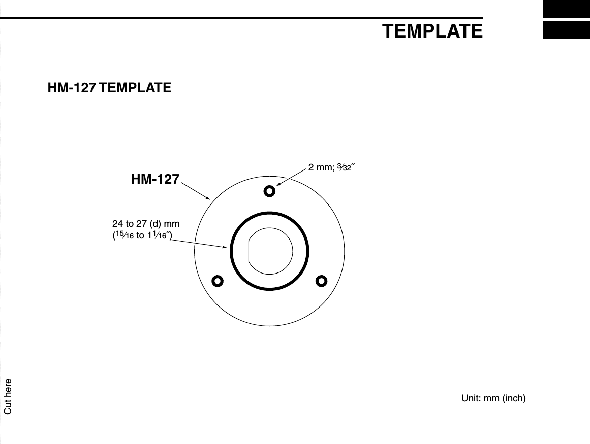
![387OTHER FUNCTIONS■Intercom operationThe optional intercom function allows you to talk to the deckfrom the cabin. The optional HM-127 REMOTE-CONTROL MI-CROPHONE is required for intercom operation.Connect an optional HM-127 as described on p. 60.• Transmitting is impossible during intercom operation.• The received signal is muted during intercom operation.qPush [F], then push [9 IC] to enter intercom mode.• The HM-127 power is automatically turned ON, even if the poweris OFF.wPush and hold [9 IC] again to call up.• The transceiver and microphone emit call beeps.ePush and hold [PTT] and speak at a normal voice level intothe microphone.• “TALK” or “LISTEN” appears on the caller or listener function dis-play, respectively.• To adjust the IC-M602’s speaker output level, rotate [VOL].• To adjust the HM-127’s speaker output level, push [Y]/[Z] afterpushing [VOL].rAfter releasing the PTT switch you can hear the responsethrough the speaker.tTo return to normal operation, push [CLR] or repeat step q.•While in the intercom mode, the transceiver functions(transmit and receive) are interrupted. If the transceiver isin transmit condition, the intercom function is not avail-able.•When a DSC call is received, the intercom function is in-terrupted and automatically return to the transceivermode. The transceiver’s display indicate “Receiving DSCcalls.” (p 32) INTBUSY-25W---INT---CALLLOCAL--DUPSCRAM--TAGNORMAL-SCANINTERCOM-34"34.206NTALK123"23.236W--UTC-10:10COMMERCIALIC-M602 (caller) HM-127 (listener)INTBUSY-25W---INT---CALLLOCAL--DUPSCRAM--TAGNORMAL-SCANINTERCOM-34"34.206N123"23.236W--UTC-10:10COMMERCIALIC-M602 HM-127](https://usermanual.wiki/ICOM-orporated/IC-M602/User-Guide-278623-Page-44.png)
![397OTHER FUNCTIONS■Hailer operationThe IC-M602 has a 2-way hailer function for voice amplifica-tion and reception over the loudspeaker, making it unneces-sary to leave the bridge to hear a hailing party.Connect an external hailer speaker as described on p. 47.• Transmitting is impossible during hailer operation.• The received signal is muted during hailer operation.qPush [F], then push [7 HAIL] to enter hailer mode.wPush and hold the PTT switch and speak at a normal voicelevel into the microphone.• “TALK” or “LISTEN” appears on the caller or listener function dis-play, respectively.• While pushing [PTT], rotate [CHANNEL] to adjust the hailer level.eAfter releasing [PTT] you can hear the response throughthe speaker.rTo return to normal operation, push [CLR] or repeat step q.• While in the hailer mode, the transceiver functions (trans-mit and receive) are interrupted. If the transceiver is intransmit condition, the hailer function is not available.•When a DSC call is received, the hailer function is inter-rupted and automatically return to the transceiver mode.The transceiver’s display indicate “Receiving DSC calls.”(p 32) BUSY-25W---INT---CALLLOCAL--DUPSCRAM--TAGNORMAL-SCANHAILER-34"34.506NLISTEN.236W___cal--1:10--CALLING____](https://usermanual.wiki/ICOM-orporated/IC-M602/User-Guide-278623-Page-45.png)
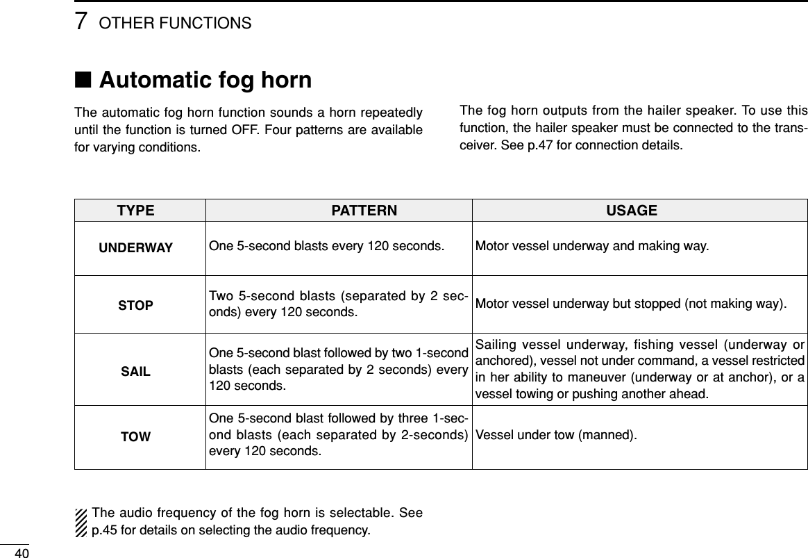
![417OTHER FUNCTIONSqPush [F], then push [8 FOG] to enter auto fog horn mode.wRotate [CHANNEL] to select the desired fog horn pattern,push [ENT].• ‘UNDERWAY,’ ‘STOP,’ ‘SAIL,’ ‘TOW’ are available. (p.40)•Even [ENT] hasn’t been pushed, the display automaticallychanges to the next step after 5 sec. inactivity.eRotate [CHANNEL] to adjust the fog horn level, push[ENT].• The fog horn level is adjustable in 7 steps.•Even [ENT] hasn’t been pushed, the display automaticallychanges to the next step after 5 sec. inactivity.rTo return to normal operation, repeat step q.When a DSC call is received, the automatic fog horn func-tion is interrupted and automatically return to the trans-ceiver mode. The transceiver’s display indicate “Receiving DSC calls.” (p 32)■Microphone lock functionThe microphone lock function electrically locks the [Y]/[Z]and [16/9] switches on the supplied microphone. This pre-vents accidental channel changes and accidental function ac-cess.➥While pushing [16/9] on the HM-136, turn power ON to tog-gle the lock function ON and OFF.BUSY-25W---INT---CALLLOCAL--DUPSCRAM--TAGReceivedCANFOG HORNOUTPUTUNDERWAYE<ENT˘OK> COMMERCIAL_______BUSY-25W---INT---CALLLOCAL--DUPSCRAM--TAGReceivedCANFOG HORNOUTPUT <CLR˘Exit>E<ENT˘OK> COMMERCIAL_______BUSY-25W---INT---CALLLOCAL--DUPSCRAM--TAGReceivedCAN˘UNDERWAY<STOP <CLR˘Exit> <ENT˘OK> COMMERCIAL](https://usermanual.wiki/ICOM-orporated/IC-M602/User-Guide-278623-Page-47.png)
![8SET MODE42Beep toneBeepScan typeScan typeWeather alertWX AlertScan resume timerScan timerAutomatic fog horn frequencyFoghornFrequencyAttenuation levelRFAttenuatorInternal speakerInternalspeakerScrambler codeScramblercodeScrambler typeScramblertypeDual/tri-watch of COMMANDMICDual/Tri COMMANDMIC LCD contrastContrastRotate or[CHANNEL]Push when using HM-127These items are not select using HM-127■Set mode programmingSet mode is used to change the conditions of the trans-ceiver’s functions: scan type (normal or priority), scan resumetimer, weather alert, dual/tri-watch of COMMAND MIC, trans-ceiver’s beep tone, internal speaker, LCD contrast, RF atten-uation level, automatic fog horn frequency, scrambler typeand scrambler code.Available functions may differ depending on dealer setting.qTurn power OFF.wWhile pushing [16•9], turn power ON to enter set mode.eAfter the display appears, release [16•9].rRotate [CHANNEL] to select the desired item, push [ENT].Or push [16•9] to select the item using an optional HM-127.tRotate the [CHANNEL] to select the desired condition ofthe item. Use [Y]/[Z] when using an optional HM-127.yTurn power OFF, then ON again to exit set mode.•SET MODE CONSTRUCTION](https://usermanual.wiki/ICOM-orporated/IC-M602/User-Guide-278623-Page-48.png)
![8SET MODE43■Set mode items◊Scan typeThe transceiver has 2 scan types: normal scan and priorityscan. Normal scan searches all tag channels in the selectedchannel group. Priority scan searches all tag channels in se-quence while monitoring channel 16.◊Scan resume timerThe scan resume timer can be selected as a pause (OFF) ortimer scan (ON). When OFF is selected, the scan pausesuntil the signal disappears. When ON is selected, the scanpauses 5 sec. and resumes even if a signal has been re-ceived on channels except for channel 16.◊Weather alertAn NOAA broadcast station transmits a weather alert tone be-fore important weather information. When the weather alertfunction is turned ON, the transceiver detects the alert, thenflashes the “WX ALERT” indicator until the transceiver is op-erated. The previously selected (used) weather channel ischecked any time during standby or while scanning.•“WX ALERT” appears instead of “WX” indication when the functionis set ON.◊Dual/Tri-watch of COMMANDMIC(Appears when connecting HM-127)This item sets the HM-127’s [CH/WX•DW] switch function asdual watch or tri-watch.Dual/Tri COMMANDMIC˘Tri-watch˘OFF--Set Mode--˘Polling Request˘Position Request˘Dualwatch˘<ENT˘OK>WX Alert˘ON˘OFF--Set Mode--˘Polling Request˘Position Request˘ON with WX SCAN<ENT˘OK>Scan Timer˘ON˘All Ships Call--Set Mode--˘Polling Request˘Position Request˘OFF<ENT˘OK>Scan Type˘Priority˘All Ships Call--Set Mode--˘Polling Request˘Position Request˘Normal<ENT˘OK>](https://usermanual.wiki/ICOM-orporated/IC-M602/User-Guide-278623-Page-49.png)
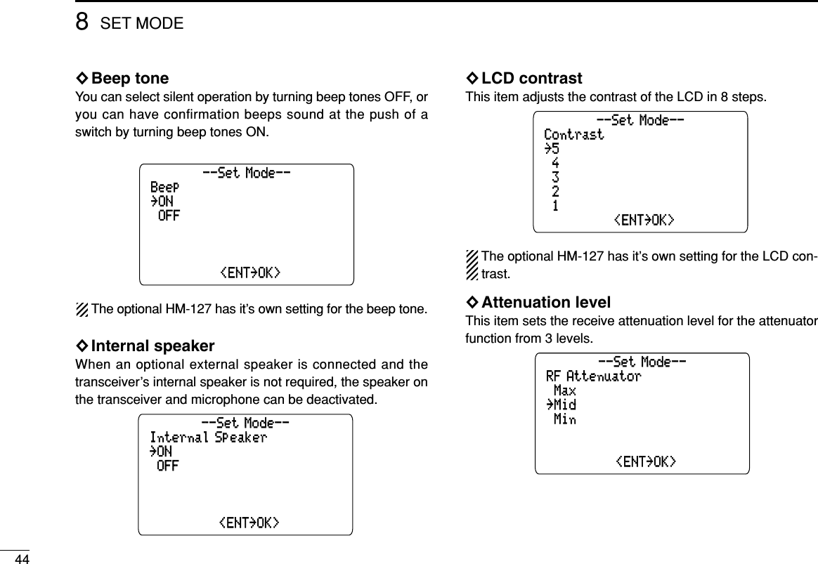
![458SET MODE◊Automatic fog horn frequencyThe audio frequency of the automatic fog horn can be ad-justed to suit your preference. While this item is selected,pushing [PTT] outputs the fog horn—experiment with the fre-quencies available until you find one you like.•Available frequency range is 200 Hz to 850Hz in 50 Hz step.◊Scrambler type (Appears when UT-112 is installed)When an optional scrambler unit is installed, the scramblertype can be selected in set mode depending on dealer set-ting.◊Scrambler code (Appears when UT-112 is installed)When an optional scrambler unit is installed, the scramblercode can be set depending on dealer setting.When the UT-112 is installed, 32 codes (1 to 32) can be se-lected.Scrambler Code˘5˘300--Set Mode--˘100˘250˘4˘<ENT˘OK>Scrambler Type˘UT-98˘300--Set Mode--˘200˘250˘UT-112˘<ENT˘OK>Foghorn Frequency˘400˘300--Set Mode--˘200˘250˘350˘<ENT˘OK>](https://usermanual.wiki/ICOM-orporated/IC-M602/User-Guide-278623-Page-51.png)
![10 TROUBLESHOOTING52PROBLEM POSSIBLE CAUSE SOLUTION REF.No power comes ON. •Bad connection to the power supply. •Check the connection to the transceiver. p. 47No sound comes fromthe speaker.•Squelch level is too deep.•Volume level is too low.•Speaker has been exposed to water.•Internal speaker is turned OFF.•Set squelch to the threshold point.•Set [VOL] to a suitable level.•Drain water from the speaker.•Turn the internal speaker ON in set mode.p. 10p. 10—p. 44Transmitting is impossi-ble, or high power can-not be selected.•Some channels are for low power or re-ceive only.•The output power is set to low.•Change channels.•Push [H/L] to select high power.pgs.8, 53p. 10Scan does not start. •“TAG ” channel is not programmed. •Set the desired channels as “TAG” chan-nels.p. 15No beep sounds. •Beep tone is turned OFF.•The squelch is open.•Turn the beep tone ON in set mode.•Set squelch to the threshold point.p. 44p. 10Receive signal cannotbe understood.•Optional voice scrambler is turned OFF.•Scramble code is not set correctly.•Turn the optional voice scrambler ON.•Reset the scramble code.p. 12p. 45Sensitivity is low. •The attenuator is activated. •Push [F], then [6 LO/DX] to turn the function OFF.p. 10Distress call cannot betransmitted.•MMSI (DSC self ID) code is not pro-grammed.•Program the MMSI (DSC self ID) code. p. 16](https://usermanual.wiki/ICOM-orporated/IC-M602/User-Guide-278623-Page-58.png)

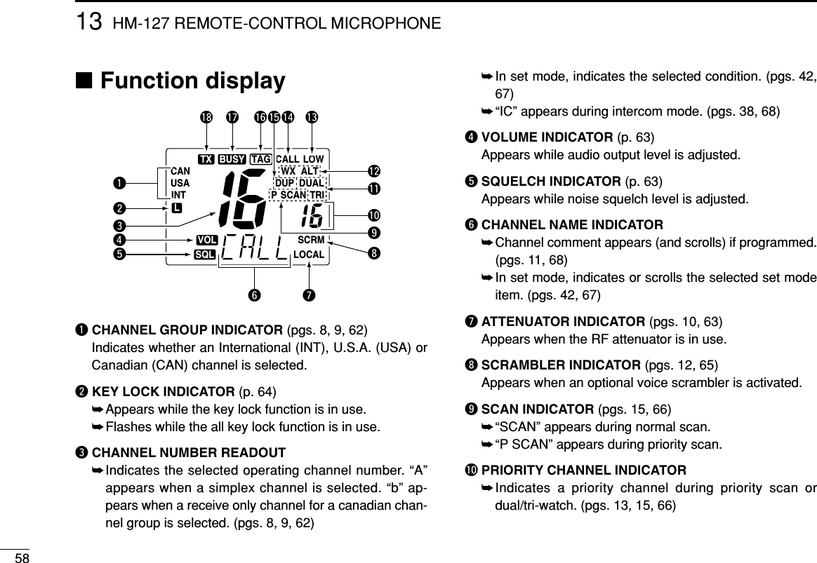
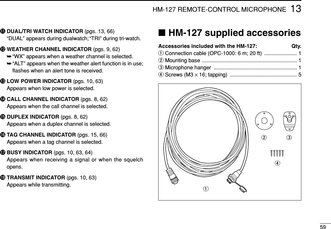
![5613 HM-127 REMOTE-CONTROL MICROPHONE OPTIONAL■Panel descriptionThe optional HM-127 remotely controls the IC-M602 and pro-vides an optional intercom function.qPOWER SWITCH [PWR] (pgs. 10, 63)Push for 2 sec. to turn the HM-127 power ON or OFFwhen the IC-M602 power is turned ON.wPTT SWITCH [PTT] (pgs. 10, 63)Push and hold to transmit; release to receive.eCHANNEL UP/DOWN SWITCHES [YY]/[ZZ] ➥Push either switch to change the operating channel, setmode contents, etc. (pgs. 10, 63)➥Push either switch to adjust audio level or noise squelchlevel after [VOL] or [SQL] is pushed, respectively. (pgs.10, 63)➥Push either switch to adjust the brightness of the LCD andswitch backlight after [VOL] is pushed for 1 sec. (p. 64)➥In set mode, changes setting of the selected item. (pgs.42, 67)➥Checks tag channels or changes scanning direction dur-ing scan. (pgs. 15, 66)rCHANNEL 16/CALL CHANNEL SWITCH [16•9]➥Selects channel 16 when pushed. (pgs. 8, 62)➥Selects call channel when pushed for 1 sec. (pgs. 8, 62)•“CALL” appears when call channel is selected.➥Push for 3 sec. to enter call channel programming con-dition when call channel is selected. (pgs. 11, 65)➥While pushing [H/L], enters memory name programmingcondition. (pgs. 11, 68)➥Enters set mode when pushed while turning power ON.(pgs. 42, 67)tCHANNEL/DUALWATCH/TRI-WATCH SWITCH[CH/WX•DW•U/I/C]➥Selects and toggles the regular channels and weatherchannel when pushed momentarily. (pgs. 8, 9, 62)qwreuytio!0](https://usermanual.wiki/ICOM-orporated/IC-M602/User-Guide-278623-Page-62.png)
![5713HM-127 REMOTE-CONTROL MICROPHONE➥While pushing [H/L], selects one of 3 regular channelsin sequence when pushed. (pgs. 8, 9, 62)•International, U.S.A. and Canadian channels are available forregular channels.➥Starts dualwatch or tri-watch when pushed for 1 sec. (pgs. 13, 66)➥Stops dualwatch or tri-watch when either is activated.yATTENUATOR/INTERCOM/SCRAMBLER SWITCH[LO/DX•IC•SCR]➥Toggles the attenuator function ON or OFF whenpushed momentarily. (pgs. 10, 63)•“LOCAL” appears when the attenuator is in use.➥Activates the intercom function when pushed for 1 sec.(pgs. 38, 68)➥Calls the IC-M602 when pushed and held while in inter-com mode. (pgs. 38, 68)➥While pushing [H/L], activates an optional voice scram-bler function. (pgs. 12, 65)•The optional voice scrambler function cannot be used onchannel 16 and 70.uSQUELCH/MONITOR/LOCK SWITCH [SQL•MONI•L] ➥[Y]/[Z] sets the squelch threshold level after pushing[SQL]. (p. 63)➥Push [SQL•MONI] for 1 sec. to turn the monitor functionON. (p. 64)➥While pushing [H/L], push [SQL•MONI•L] to toggle themicrophone key lock function ON or OFF. (p. 64)•“ T” appears while key lock function is in use.•[PWR], [PTT], [VOL], [SQL] and [H/L] still function when themicrophone key lock function is turned ON.➥Advance the cursor while in memory name program-ming condition. (pgs. 11, 68)iVOLUME/DIMMER SWITCH [VOL•DIM] ➥[Y]/[Z] adjusts the audio level after pushing [VOL]. ➥Push [VOL•DIM] for 1 sec. to adjust the brightness ofthe LCD and switch backlight. (p. 64)➥Move the cursor backward while in memory name pro-gramming condition. (pgs. 11, 68)oTRANSMIT POWER SWITCH [H/L] ➥Toggles high and low power when pushed. (pgs. 10, 63)• Some channels are set to low power only.➥While pushing this switch, other switches perform sec-ondary functions.➥Toggles the all key lock function ON or OFF whenpushed while turning power ON. (p. 64)•“ T” flashes while the all key lock function is in use.•Only [PWR] and [PTT] function when the all key lock functionis in use.!0 SCAN SWITCH [SCN•TAG] (pgs. 15, 66)➥Starts and stops normal or priority scan when tag chan-nels are programmed.➥Push [SCN•TAG] for 1 sec. to set the displayed channelas a tag (scanned) channel. ➥While pushing [H/L], push for 3 sec. to clear all tag chan-nels.](https://usermanual.wiki/ICOM-orporated/IC-M602/User-Guide-278623-Page-63.png)
![6213 HM-127 REMOTE-CONTROL MICROPHONE■Channel selection◊Channel 16qPush [16] to select channel 16.wPush [CH/WX] to return to thecondition before selecting chan-nel 16, or push [Y] or [Z] to se-lect operating channel.◊Call channelqPush [16•9] for 1 sec. to selectcall channel.wPush [CH/WX] to return to thecondition before selecting callchannel, or push [Y] or [Z] to se-lect operating channel.◊Weather channelsqPush [CH/WX] once or twice toselect weather channel group.wPush [Y] or [Z] to select weatherchannel.ePush [CH/WX] to return to thecondition before selecting theweather channel group.◊U.S.A., International and Canadian channelsqPush [CH/WX] to select regular channel.• Push [CH/WX] again, if weather channel appears.wPush [CH/WX•U/I/C], while pushing [H/L], to select chan-nel group.• U.S.A., International and Canadian channels can be selected insequence.PushPush for 1 sec.PushPush while pushingU.S.A. channelsCanadian channelsInternational channels++](https://usermanual.wiki/ICOM-orporated/IC-M602/User-Guide-278623-Page-68.png)
![6313HM-127 REMOTE-CONTROL MICROPHONE■Receiving and transmittingqPush [PWR] to turn power ON.wPush [VOL], then [Y]/[Z] to adjust audio output level.• Push [SQL], then [Y]/[Z] to mute any audio noise, if necessary.ePush [Y]/[Z] to select the desired channel.•When receiving a signal, “ ” appears and audio is emittedfrom the speaker.• Further adjustment of audio level may be necessary at this point.• Use the optional voice scrambler function for privacy. (pgs. 12, 65)rPush [H/L] to select the output power, if necessary.• “LOW” appears when low power is selected.•Choose low power for shorter, high power for longer distancecommunications.• Some channels are low power only.tPush and hold [PTT] to transmit, then speak into the mi-crophone.• “ ” appears.• Channel 70 cannot be used for transmission (for GMDSS use).Simplex channels, 3, 21, 23, 61, 64, 81, 82 and 83 CAN-NOT be lawfully used by the general public in U.S.A. wa-ters.yRelease [PTT] to receive.IMPORTANT: To maximize the readability of your trans-mitted signal (voice), pause a few sec. after pushing [PTT],hold the microphone 1 to 2 inches (2.5 to 5 cm) from yourmouth and speak at a normal voice level.■RF attenuator function➥Push [LO/DX] to turn the RFattenuator function ON andOFF.w Set volumew Set squelch, if requiredr Set output powert Speak into microphoneq Turn power ONe Set channelt Push to transmity Release to receiveAppears when the RFattenuator function is in use](https://usermanual.wiki/ICOM-orporated/IC-M602/User-Guide-278623-Page-69.png)
![6413 HM-127 REMOTE-CONTROL MICROPHONE■Lock functionsThe lock function electronically locks keys and switches toprevent accidental changes and function access from the mi-crophone.• All keys, switches and controllers on the transceiver are functional.◊Activating the lockfunction➥Push [SQL] while pushing[H/L] to turn the lock functionON or OFF.• “ ” appears.•Only [PWR], [PTT], [H/L],[SQL•MONI], [VOL]+[Y]/[Z] and[SQL]+[Y]/[Z] are functional.◊Activating the all keylock function➥Turn the power ON by pushing[PWR] while pushing [H/L] toturn the all key lock functionON or OFF.• “ ” flashes.• Only [PWR] and [PTT] are func-tional.■Display backlightingThe function display and switches can be backlight for bettervisibility under low light conditions. And the backlighting con-dition can be adjusted independently from the transceiver.qPush [VOL•DIM] for 1 sec. to enter backlight adjustingmode.• “ ” with number of backlight level appears in the channel nameindicator.wPush [Y]/[Z] to adjust the backlight level.•The backlight level is adjustable between 0 (lights OFF) and 7(brightest).For your reference:Pushing [Y]/[Z], while [H/L] is pushed, also adjusts backlightlevel.• No backlight level indication is available.■Monitor functionThe monitor function releases the noise squelch mute of themicrophone only. (An independent noise squelch system isemployed.)➥Push [SQL•MONI] for 1 sec. to activate the monitor func-tion.• “ ” flashes and audio is emitted.• Any key cancels the monitor function.Appears when the lockfunction is in use. Flashes when the all lockfunction is in use.](https://usermanual.wiki/ICOM-orporated/IC-M602/User-Guide-278623-Page-70.png)
![6513HM-127 REMOTE-CONTROL MICROPHONE■Call channel programmingqPush [CH/WX•U/I/C] several timeswhile pushing [H/L] to select thedesired channel group (USA, INT,CAN) to be programmed.wPush [16•9] for 1 sec. to select thecall channel of the selected chan-nel group.•“CALL” and call channel number ap-pear.ePush [16•9] again for 3 sec. (untillong beep changes to 2 shortbeeps) to enter call channel pro-gramming condition.•Call channel number and channelgroup to be programmed flashes.rPush [Y]/[Z] to select the desiredchannel.tPush [16•9] to program the dis-played channel as the call channel.• The call channel number and channelgroup stop flashing.■Optional voice scrambleroperation◊Activating the scramblerqSelect an operating channel, except channel 16, channel70 or weather channels.wPush [LO/DX•IC•SCR] whilepushing [H/L] to turn thevoice scrambler function ON.• “SCRM” appears.eTo turn the scrambler func-tion OFF, repeat step w.• “SCRM” disappears.◊Programming scramble codesThere are 32 codes (01 to 32) available with the UT-112 forprogramming. In order to understand one another, all trans-ceivers in your group must have the same scrambler code.The scrambler code is programmed in set mode. See pgs.12, 45 for details.Appears when the voicescrambler function is in use.](https://usermanual.wiki/ICOM-orporated/IC-M602/User-Guide-278623-Page-71.png)
![6613 HM-127 REMOTE-CONTROL MICROPHONE■Starting a scanqPush [CH/WX•U/I/C] several timeswhile pushing [H/L] to select thechannel group (USA, INT, CAN), ifdesired.•When the weather alert function is inuse, select the desired weather channelwith [CH/WX] and [Y]/[Z].wPush [SCN] to start priority or normalscan.• “SCAN” appears during normal scan.•The priority channel readout indicates“16”, and “P” and “SCAN” indicators ap-pear during priority scan.• When a signal is received, scan pausesuntil the signal disappears or resumesafter pausing 5 sec. according to setmode setting (Channel 16 is still moni-tored during priority scan).• Push [Y]/[Z] to check the scanning tagchannels, to change the scanning direc-tion or resume the scan manually.eTo stop the scan, push [SCN].• “SCAN” disappears.•Pushing [PTT], [16•9] or [CH/WX] alsostops the scan.■Setting tagchannelsqPush [CH/WX•U/I/C] several timeswhile pushing [H/L] to select thechannel group (USA, INT, CAN), ifdesired.wPush [Y]/[Z] to select the desiredchannel to set as a tag channel.ePush [SCN•TAG] for 1 sec. to set thedisplayed channel as a tag channel.• “ ” appears.rTo cancel the tag channel setting,push [SCN•TAG] for 1 sec.• “ ” disappears.•Clearing all tag channels in theselected channel group➥Push [SCN•TAG] while pushing [H/L]for 3 sec. (until long beep changes to2 short beeps).■Dualwatch/Tri-watch operationqPush [Y]/[Z] to select the desiredchannel.• Push [CH/WX•U/I/C] several times whilepushing [H/L] to select the channelgroup (USA, INT, CAN), if desired.wPush [CH/WX•DW] for 1 sec. to startdualwatch or tri-watch.• “DUAL” appears during dualwatch; “TRI”appears during tri-watch.•Beep tone sounds when a signal is re-ceived on channel 16.• Tri-watch becomes dualwatch when re-ceiving a signal on the call channel.• Dualwatch or tri-watch can be selectedon the transceiver’s set mode.eTo cancel dualwatch/tri-watch, push[CH/WX•DW] again.](https://usermanual.wiki/ICOM-orporated/IC-M602/User-Guide-278623-Page-72.png)
![6713HM-127 REMOTE-CONTROL MICROPHONE■Set mode programmingSet mode is used to change the condition of the transceiver’sfunctions and the microphone’s own functions:Transceiver’s functions— scan type (normal or priority), scan resume timer, weatheralert, dualwatch/tri-watch of COMMANDMIC, transceiver’sbeep tone, internal speaker (transceiver), LCD contrast(transceiver), RF attenuation level, foghorn frequency, scram-bler type and scrambler code.Microphone’s own functions— beep tone function (microphone) and LCD contrast (micro-phone).In this section, instructions are for the microphone’s own func-tions only. Refer pgs. 42–45 for the setting of the other func-tions. (Some functions may not be selected from the micro-phone.)◊Entering set modeqTurn power OFF.wWhile pushing [16•9], turn power ON.• After beep emission, a set mode item (in the channel name indi-cator and condition in the channel number readout) is displayed.ePush [16•9] to select the desired item, if necessary.rPush [Y]/[Z] to select the desired condition of the item.tTurn power OFF, then ON to exit set mode.•Beep tone “BEEP”➥Push [Y] to turn ON, [Z] to turn OFF the beep output. •LCD contrast “LCD CONTRAST”➥Push [Y]/[Z] to adjust to a suitable LCD contrast.Push• •• •Push](https://usermanual.wiki/ICOM-orporated/IC-M602/User-Guide-278623-Page-73.png)
![6813 HM-127 REMOTE-CONTROL MICROPHONE■Intercom operationqPush [LO/DX•IC] for 1 sec. to ac-tivate the intercom function.• “IC” appears in the channel readout.• The channel name disappears.wPush [PTT] to talk.•“ ” appears in the channelname indicator.eRelease [PTT] to listen.•“ ” appears in the channel name indicator when the trans-ceiver is in talking.rPush [LO/DX•IC] to cancel the intercom function.• Pushing [16], [SCN•TAG] or [CH/WX] also cancels the intercomfunction.For your reference:In case the intercom mode is selected with the transceiverduring microphone power OFF, the microphone power is au-tomatically turned ON and the intercom mode is selected.◊Intercom beep function➥Push [LO/DX•IC] for more than 1 sec.• Emits intercom beep while holding.■Channel namesqPush [Y]/[Z] to select a channel to program the channel name.• Push [CH/WX•U/I/C] several times while pushing [H/L] to selectthe channel group (USA, INT, CAN), if desired.wWhile pushing [H/L], push [16•9].• The 1st character of the currently programmed comment flashes.ePush [Y]/[Z] to select a character.rPush [SQL] to move to right; then push [Y]/[Z] to select acharacter.• Push [VOL] to move to left.tContinue until the desired characters have been selected,then push [16•9] to return to normal operation.•Available characters(r)(s) (t) (u) (v) (w) (x) (y) (z)(q)(3)(D)(N)(X)(h)(+)(4)(E)(O)(Y)(i)(–)(5)(F)(P)(Z)(j)(✱)(6)(G)(Q)(a)(k)(/)(7)(H)(R)(b)(l)(,)(8)(I)(S)(c)(m)(space)(9)(T)(d)(n)(0)(A)(U)(e)(o)(1)(B)(V)(f)(p)(2)(C)(J) (K) (L)(M)(W)(g)(.)( ))(( )(’)(&)(%)($)(#)(")(!)Appears when the inter-com function is in use.](https://usermanual.wiki/ICOM-orporated/IC-M602/User-Guide-278623-Page-74.png)