ICOM orporated IC-M802 IC-M802 User Manual manual
ICOM Incorporated IC-M802 manual
UserManual.wiki
>
ICOM orporated
>
IC M802 User Manual
manual
Navigation menu
Upload a User Manual
Namespaces
Wiki Guide
HTML
PDF
Info
Views
User Manual
Discussion / Help
Navigation
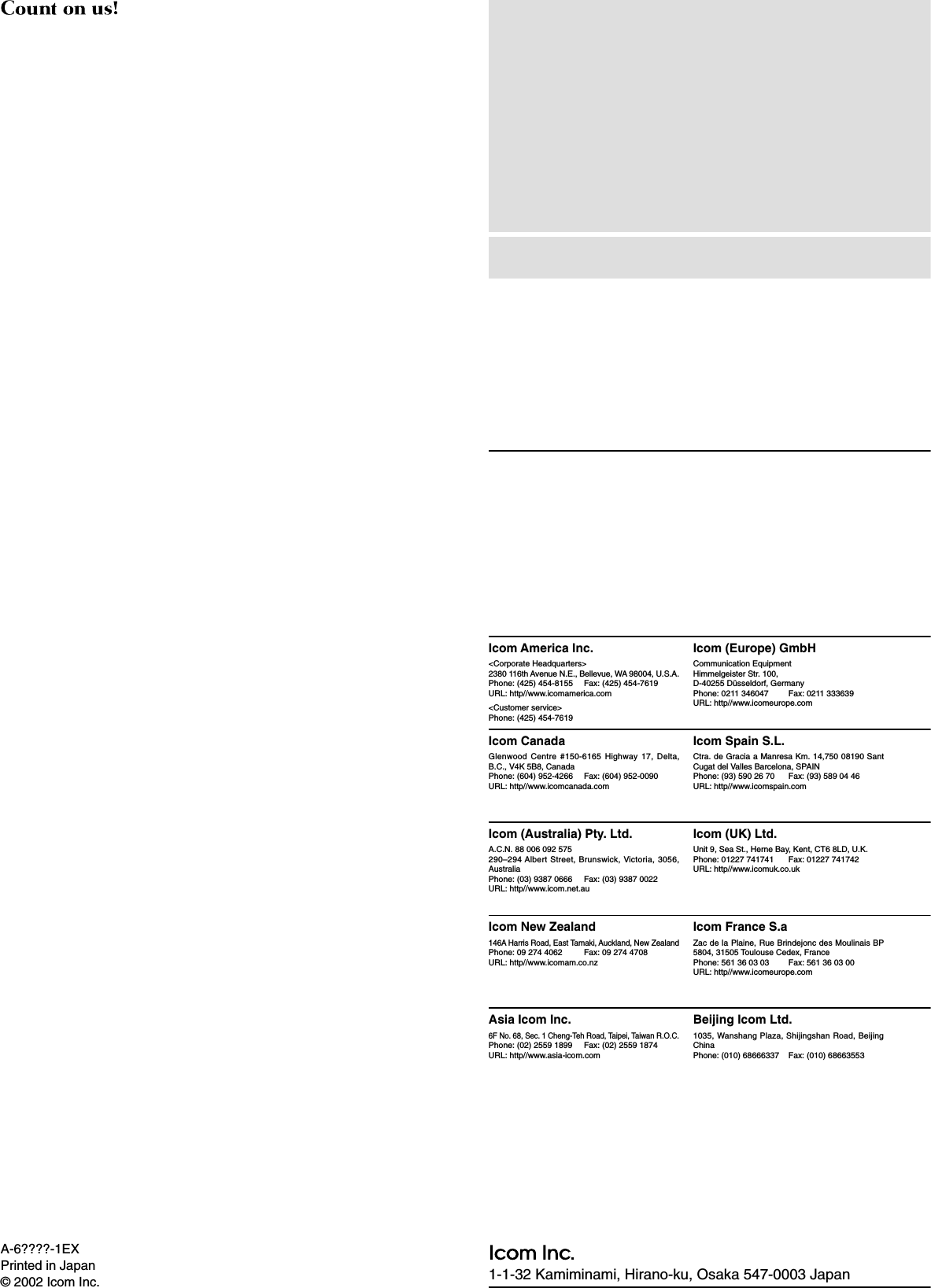
![iiIf your vessel requires assistance, contact other ves-sels and the Coast Guard by sending a distress call on2182 kHz.Or transmit your distress call using digital selectivecalling on 2187.5 kHz.IN CASE OF EMERGENCY (for maritime operation)DUSING 2182 kHz WITH VOICEqPush [2182kHz] to select the emergency fre-quency.wPush [ALARM] and [TX FREQ] for 1 sec. totransmit a two tone alarm signal for at least30 sec.•The transceiver automatically stops the alarm after50 sec.ePush [ALARM] to turn OFF the alarm transmis-sion, then push and hold the PTT switch on themicrophone and send the following information.1. “MAY DAY, MAY DAY, MAY DAY.”2. “THIS IS. . . . . . . . . ” (name of vessel)3. “LOCATED AT . . . . ” (vessel's position)4. Give the reason for the distress call.5. Explain what assistance you need.6. Give additional information:• Vessel type• Vessel length• Vessel color• Number of people on-boardDUSING DIGITAL SELECTIVE CALLINGWhen immediate help is neededqPush and hold [DISTRESS] for 5 sec. until theshort beeps become one long beep, to send thedistress call.wAfter 2182 kHz is automatically selected, trans-mit the appropriate information as at left usingvoice.When potential problems existsqPush [SEL], then select “All ships call” with [CH]selector.wPush and hold [CANCEL/CALL] for 5 sec. untilthe short beeps becomes one long beep, to usethe “all ships call” function.eAfter the pre-selected frequency is selected,transmit the appropriate information using voice.• DSC equipped ships may monitor your transmission.](https://usermanual.wiki/ICOM-orporated/IC-M802/User-Guide-233099-Page-3.png)
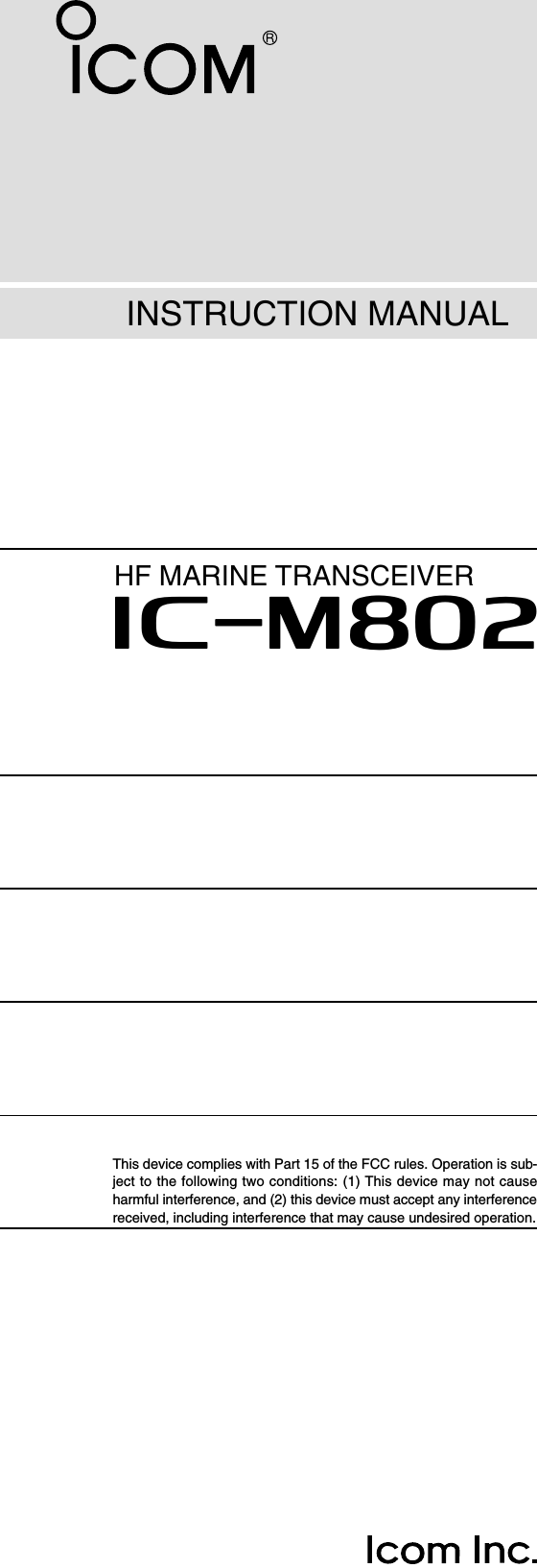
![22PANEL DESCRIPTION■Front panel— ControllerqDISTRESS SWITCH [DISTRESS] (p. 00)Push for 5 sec. to make a distress call.wDSC SWITCH [DSC] ➥Selects DSC function when pushed. (p. 00)• Select DSC channel with [CH].➥After pushing [F], print out the selected contents,when a printer is connected. (p. 00)eCANCEL/CALL SWITCH [CANCEL/CALL] ➥Cancels a distress call. (p. 00)➥Push for 1 sec. to make a DSC call. (p. 00)rHEADPHONE JACK [ ]Accepts headphones.• Output power: 5 mW with an 8 Ωload.• When headphones are connected, the internal speakeror connected external speaker does not function.tMICROPHONE CONNECTOR [MIC]Accepts the supplied or optional microphone orhandset.• See p. 00 for appropriate microphones.• See p. 00 for microphone connector information.yGROUP CHANNEL SELECTOR [GRP] (p. 00)Selects groups in 20 channel steps and ITU marinechannel groups.NOTE: Some versions have no ITU channels.uCHANNEL SELECTOR [CH] (p. 00)➥Selects an operating channel within the selectedchannel group such as ITU channels. (p. 00)•User channels can be selected from 1 to 160 (max.)in sequence regardless of the channel group.➥Changes the operating frequency* after[RXCLAR] is pushed (while “å” appears).•The changed frequency is not programmed in thisway.iRX/CLARITY SWITCH [RXCLAR] (p. 00)➥Push to enable the receive frequency set with thekeypad or [CH] selector. (p. 00)• While receive frequency set is enabled, “å” appears.➥After pushing [F], turns clarity function ON andOFF.• [CH] selector is used for clarity control.➥After pushing [DSC], shows received DSC mes-sages.•[GRP] selector is used for Distress and Individual callselection.• [CH] selector is used for message selection.oPOWER SWITCH [POWER] ➥Push to turn the power ON.➥Push for 1 sec. to turn the power OFF.!0 TX/TRANSMIT FREQUENCY SWITCH [TXTXF](p. 00)➥Push to enable the transmit frequency set withthe keypad. (p. 00)• While transmit frequency set is enabled, “TX” blinks.➥After pushing [F], displays the transmit fre-quency, and opens the squelch. Checks and mon-itors the transmit frequency while holding. (p. 00)DISTRESSqwertyuio!0 !1!2!3!4!5!6!7Function display (p. 00)*Some versions do not have frequency selection and fre-quency indication.](https://usermanual.wiki/ICOM-orporated/IC-M802/User-Guide-233099-Page-5.png)
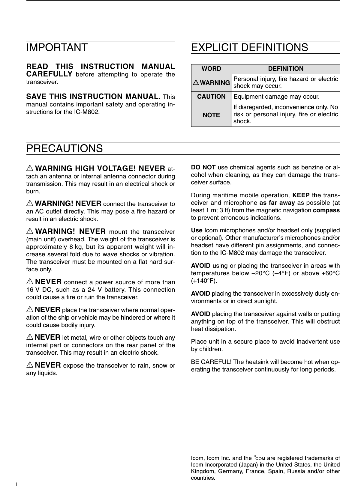
![32PANEL DESCRIPTION!1 VOLUME CONTROL [VOL] (p. 00)Adjusts the audio output level.•Audio does not come from the speaker when:- A microphone is not connected.- The speaker switch is turned ON.- The squelch switch is turned ON and no signal is beingreceived.!2 FUNCTION SWITCH [F] (p. 00)After pushing, activates the secondary functions.•“F” appears when when a secondary function can beaccessed.!3 KEYPAD (p. 00)➥Input numeral “1” for channel number,frequency input, etc.➥Input “1,” “Q” or “Z” for channel commentinput.➥After pushing [F], turns the noiseblanker function ON and OFF. (p. 00)➥Input numeral “2” for channel number,frequency input, etc.➥Input “2,” “A,” “B” or “C” for channel com-ment input.➥After pushing [F], turns the voice or S-meter squelch ON and OFF. (p. 00)➥Input numeral “3” for channel number,frequency input, etc.➥Input “3,” “D,” “E” or “F” for channel com-ment input.➥After pushing [F], starts and stops thescan function. (p. 00)➥Input numeral “4” for channel number,frequency input, etc.➥Input “4,” “G,” “H” or “I” for channel com-ment input.➥After pushing [F], turns the speaker out-put ON and OFF. (p. 00)➥Input numeral “5” for channel number,frequency input, etc.➥Input “5,” “J,” “K” or “L” for channel com-ment input.➥After pushing [F], turns the AGC functionON and OFF. (p. 00)➥Input numeral “6” for channel number,frequency input, etc.➥Input “6,” “M,” “N” or “O” for channel com-ment input.➥After pushing [F], enters to the RF gainadjustment mode. (p. 00)➥Input numeral “7” for channel number,frequency input, etc.➥Input “7,” “P, ” “R” or “S” for channel com-ment input.➥After pushing [F], selects low transmitoutput power. (p. 00)➥Input numeral “8” for channel number,frequency input, etc.➥Input “8,” “T,” “U” or “V” for channel com-ment input.➥After pushing [F], selects middle trans-mit output power. (p. 00)➥Input numeral “9” for channel number,frequency input, etc.➥Input “9,” “W,” “X” or “Y” for channel com-ment input.➥After pushing [F], selects high transmitoutput power. (p. 00)➥Input numeral “0” for channel number,frequency input, etc.➥Input “0” and symbols (as follows) forchannel comment input.➥Fixes input of channel number, frequencyand channel comment, etc. ➥When pushed for 1 sec., stores pro-grammed frequency, operating mode andmemory comment into a channel.➥After pushing [F], clears clarity setting.➥Selects display type:When channel comment indication is ON;switches transmit frequency indicationON and OFFwhen channel comment indication is OFF;switches channel comment indicationON and OFF➥After pushing [F], enters channel com-ment programming mode, when channelcomment indication is ON.!4 SET SWITCH [SET] ➥Enters quick set mode (p. 00)➥After pushing [DSC], enters DSC set mode.(p. 00)!5 TUNE/THROUGH SWITCH [TUNETHRU] (p. 00)➥Starts tuning when an optional antenna tuner isconnected. •“TUNE” appears when tuned.•When the tuner cannot tune the antenna, the tuningcircuit is bypassed automatically after 20 sec.➥After pushing [F], bypasses an external antennatuner. •“THROUGH” appears instead of “TUNE” indication.!6 MODE/DIMMER SWITCH [MODEDIM](p. 00)➥Push to select an operating mode.•J3E, H3E, LSB, J2B, F1B and A1A modes are avail-able, depending on version or countries.➥After pushing [F], selects LCD backlight bright-ness.!7 E-MAIL SWITCH [e-mail] (p. 00)➥Selects the operating frequencies, mode and fil-ter setting for e-mail operation.](https://usermanual.wiki/ICOM-orporated/IC-M802/User-Guide-233099-Page-6.png)
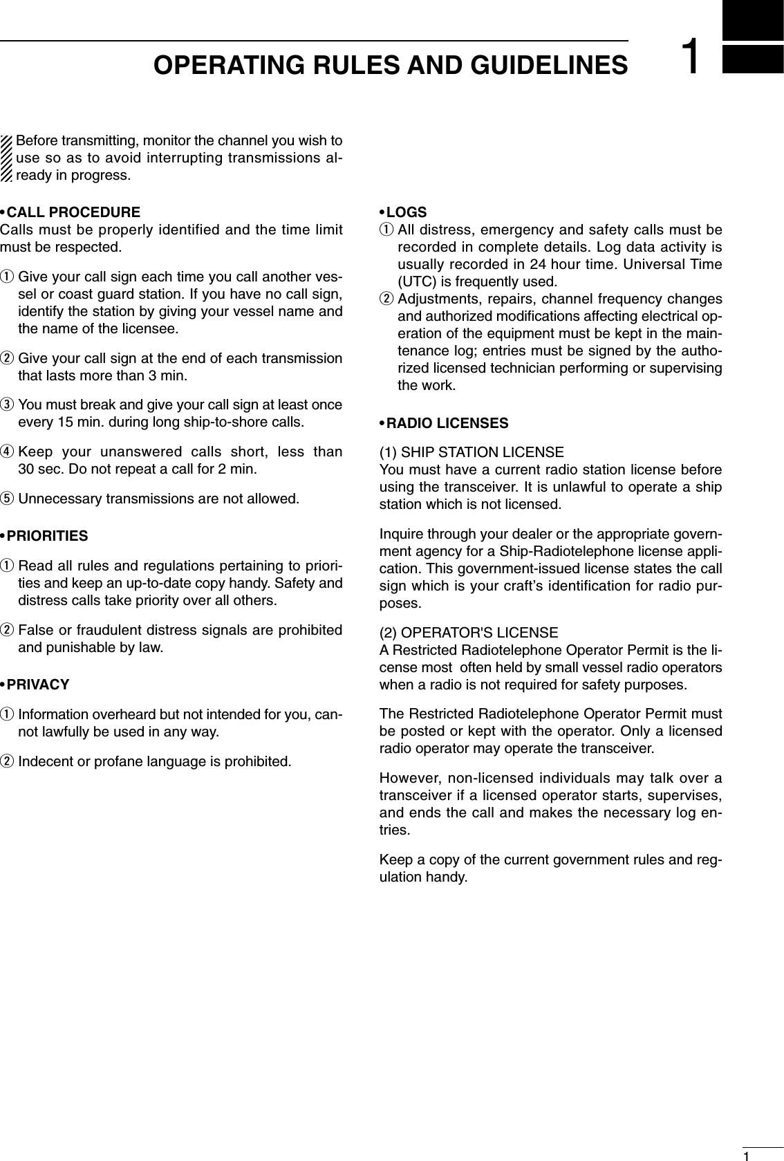
![■Front panel— Main unit qGPS CONNECTOR [GPS] (p. 00)Connects a GPS receiver (NMEA0183 ver. 2.0) forsending positioning data without manual input.wREMOTE CONNECTOR [REMOTE] (p. 00)Connects the IC-M802 to a PC via an RS-232Ccable (9-pin) for remote control of transceiver func-tion in the NMEA format.eAF/MOD CONNECTOR [AF/MOD] (p. 00)Connects the IC-M802 to an NBDP system via anRS-232C cable (9-pin).rACC CONNECTOR [ACC] (p. 00)Connects a CW keyer or an FSK terminal unittCONTROLLER CONNECTOR [CONTROLLER](p. 00)Connects the supplied remote controller.ySPEAKER JACK [SP] (p. 00)Connects the supplied external speaker.42PANEL DESCRIPTIONqw erty](https://usermanual.wiki/ICOM-orporated/IC-M802/User-Guide-233099-Page-7.png)
![52PANEL DESCRIPTION■Rear panel— Main unit qTUNER CONTROL SOCKET (p. 00)Connects a control cable to an optional antennatuner, AT-140, AT-130/E ANTENNA TUNER, A femaleconnector is supplied for connection.wGROUND TERMINAL (p. 00)IMPORTANT! Connects a vessel's (or vehicle's)ground. See p. 00 for details.eANTENNA CONNECTOR 1 (p. 00)Connects a 50 ΩHF band antenna with a 50 Ωmatched coaxial cable and a PL-259 plug for bothtransmit and receive operation.rANTENNA CONNECTOR 2 (p. 00)Connects a 50 ΩHF band antenna with a 50 Ωmatched coaxial cable and a PL-259 plug for DSCreceive operation only.tDC POWER SOCKET (p. 00)Accepts 13.6 V DC through the supplied DC powercable.qwe r t■Microphone (HM-135)qPTT SWITCH [PTT]Push and hold to transmit; release to receive.wUP/DOWN SWITCHES [∫∫]/[√√](p. 00)Push either switch to change the operating channel,set mode contents, etc.eUSER PROGRAMMABLE SWITCH [P] (p. 00)Push to activate or deactivate a function, selectedin set mode (p. 00).SpeakerMicrophonewqe](https://usermanual.wiki/ICOM-orporated/IC-M802/User-Guide-233099-Page-8.png)
![qRECEIVE INDICATOR“RX” appears when signals are received or thesquelch is open.wTUNE INDICATOR (p. 00)“TUNE” blinks while tuning, if an optional externalantenna tuner is connected.•“TUNE” appears after tuning is completed and the tuneris ON when AH-3 is connected. eOPERATING MODE INDICATOR (p. 00)Shows the selected operating mode.•“J3E,” “H3E,” “LSB,” “J2B,” “F1B” or “A1A” appearsdepending on version.rSIMPLEX/DUPLEX INDICATOR (p. 00)“SIMP” appears when a simplex channel, “DUP”appears when a duplex channel is selected.tCLARITY INDICATOR (p. 00)“CLAR” appears when the clarity function is acti-vated and shows shifting frequency in Hz.yCHANNEL NAME INDICATIONShows the programmed channel names.•Shows the programmed receive frequency when nochannel names are programmed.uCHANNEL NUMBER INDICATIONShows the selected channel number.iSPEAKER OFF INDICATOR (p. 00)“” appears when the speaker output is turnedOFF.oAGC OFF INDICATOR (p. 00)“” appears when the AGC is turned OFF.!0 DSC WATCH INDICATOR (p. 00)“DSC Watch” appears while the DSC receiver isactivated.!1 NOISE BLANKER INDICATOR (p. 00)“NB” appears when the noise blanker function is ac-tivated.!2 SQUELCH INDICATOR (p. 00)“SQL” appears when the squelch is open.!3 S/RF INDICATOR (p. 00)Shows relative transmit output power levels duringtransmit and receiving signal strength during re-ceive.!4 GPS INDICATOR (p. 00)Shows position and UTC time when a GPS receiveris connected. The indication is up dated each timenew GPS data is received.•If no GPS receiver is connected, the position and UTCtime must be set in advance.!5 TRANSMIT INDICATOR (p. 00)➥“TX” appears during transmit.➥“TX” blinks when setting a transmit frequency orduring cross channel operation.!6 RECEIVE FREQUENCY READOUT (p. 00)Shows receive frequency.!7 TRANSMIT FREQUENCY READOUT (p. 00)Shows transmit frequency.!8 RECEIVE FREQUENCY SELECT MODE INDICATOR (p. 00)“å” appears while in receive frequency select mode.!9 CURSOR (p. 00)Shows the changeable receive frequency digit.•The cursor moves by rotating the [GRP] selector whilein receive frequency select mode.AGCSP62PANEL DESCRIPTION■LCD screenThe IC-M802 has 2 display types, one is channelname indication and other one is frequency indication.These display types can be switched with a push of abutton, depending on versions and set modes setting.See p. 00 and p. 00 for display type settings.• Channel name indication • Frequency indicationNBLHCHCLAR0SPAGCDSC Watch ---GPS---UTC 16:23Lat 45 59'NLon134 44'ERX TUNE J3E SIMP NBC HCLAR 0SPAGCUTC 16:23RX TUNEå J3E SIMP](https://usermanual.wiki/ICOM-orporated/IC-M802/User-Guide-233099-Page-9.png)
![37SELECTING A CHANNEL/FREQUENCY■Selecting a channelThe transceiver as 160 user channels and ITU chan-nels. However, the number of user channels can beoptionally restricted and ITU channels are not availablewith some versions.☞NOTE: When Channel 0 or 2182 kHz is selectedwith the [2182kHz] switch, channel selection is NOTpossible. In such case, push [2182kHz] in advance.☞NOTE: Channel name (alphanumeric) may not ap-pear during channel indication depending on setmode setting. C HUTC 16:23RXå J3E SIMPC HUTC 16:23RX J3E SIMPCHDSC Watch ---GPS---UTC 16:23Lat 45 59'NLon134 44'ERXå J3E SIMPLHCHDSC Watch ---GPS---UTC 16:23Lat 45 59'NLon134 44'ERX J3E SIMPLHCHANNELindicationFREQUENCYindicationCHANNEL SELECTION MODEchannel can be selectedFREQUENCY SELECTION MODEfrequency can be changedDDUsing the channel selectorThe transceiver has two large controls for group se-lection and channel selection. The [GRP] selectorchanges channels in 20 channel increments and se-lects ITU channel groups*; and the [CH] selector se-lects each channel.qMake sure no “å” indicator appears in the display.wRotate [GRP] selector to select the desired chan-nel group as shown at right and/or below.eRotate [CH] selector to select the desired channel.[EXAMPLE]: Selection with the [GRP] selector*All ITU channels are not available with some versions andITU FSK channels can be hidden using set mode (p 00).ITU SSB channels*ITU FSK channels*CHDSC Watch ---GPS---UTC 16:23Lat 45 59'NLon134 44'ERX J3E SIMPLHCHDSC Watch ---GPS---UTC 16:23Lat 45 59'NLon134 44'ERX J3E SIMPLHCHDSC Watch ---GPS---UTC 16:23Lat 45 59'NLon134 44'ERX J3E SIMPLHCHDSC Watch ---GPS---UTC 16:23Lat 45 59'NLon134 44'ERX J3E SIMPLHCHDSC Watch ---GPS---UTC 16:23Lat 45 59'NLon134 44'ERX J3E SIMPLHCHDSC Watch ---GPS---UTC 16:23Lat 45 59'NLon134 44'ERX J3E DUPLHCHDSC Watch ---GPS---UTC 16:23Lat 45 59'NLon134 44'ERX J3E SIMPLHCHDSC Watch ---GPS---UTC 16:23Lat 45 59'NLon134 44'ERX J3E DUPLHCHDSC Watch ---GPS---UTC 16:23Lat 45 59'NLon134 44'ERX J3E SIMPåLHCHDSC Watch ---GPS---UTC 16:23Lat 45 59'NLon134 44'ERX F1B DUPLHCHDSC Watch ---GPS---UTC 16:23Lat 45 59'NLon134 44'ERX J3E SIMPåLHIf appears, push to delete it.](https://usermanual.wiki/ICOM-orporated/IC-M802/User-Guide-233099-Page-10.png)
![83SELECTING A CHANNEL/FREQUENCYDDUsing the keypadDirect channel selection via the keypad is availablefor quick channel selection.qMake sure no “å” indicator appears in the display.•If it appears, push [RXCLAR] to delete it.wEnter the desired channel number via the keypad.•A user channel is selected when channel 1–160 isinput (max. number may be optionally restricted).•An ITU SSB channel is selected when channel num-bers higher than 401 are input (not available for someversions).•An ITU FSK channel is selected when channel num-bers higher than 4001 are input (not usable accordingto set mode setting).•When selecting an ITU simplex channel, push [0] threetimes instead of the “–” input. (e.g. When selecting the channel 4-1;— push [4SP], [0], [0], [0] then [1NB].) ePush [ENTCE] to select the channel.[EXAMPLE]: Selecting channel 158LHCHDSC Watch ---GPS---UTC 16:23Lat 45 59'NLon134 44'ERX J3ECHDSC Watch ---GPS---UTC 16:23Lat 45 59'NLon134 44'ERX J3ECHDSC Watch ---GPS---UTC 16:23Lat 45 59'NLon134 44'ERX J3ECHDSC Watch ---GPS---UTC 16:23Lat 45 59'NLon134 44'ERX J3ECHDSC Watch ---GPS---UTC 16:23Lat 45 59'NLon134 44'ERX J3E SIMPLHLHLHLHCHANNEL GROUPS*1[GRP] selector changes in 20 channels steps. *2SITOR use— no group separation.Channel No. Description Channel No. Description Channel No. Description1 to 160 User ch.*18-1 to 8-9 8 MHz ITU simplex ch. 18-1 to 18-9 18 MHz ITU simplex ch.401 to 427 4 MHz ITU duplex ch. 1201 to 1241 12 MHz ITU duplex ch. 2201 to 2253 22 MHz ITU duplex ch.4-1 to 4-9 4 MHz ITU simplex ch. 12-1 to 12-9 12 MHz ITU simplex ch. 22-1 to 22-9 22 MHz ITU simplex ch.601 to 608 6 MHz ITU duplex ch. 1601 to 1656 16 MHz ITU duplex ch. 2501 to 2510 25 MHz ITU duplex ch.6-1 to 6-9 6 MHz ITU simplex ch. 16-1 to 16-9 16 MHz ITU simplex ch. 25-1 to 25-9 25 MHz ITU simplex ch.801 to 832 8 MHz ITU duplex ch. 1801 to 1815 18 MHz ITU duplex ch. 4001 to 25040 ITU FSK duplex ch.*2DDUsing scan function(some versions do not have these functions)The transceiver has automatic channel or frequencychange capability (scan function). There are 3 typesof scan functions available to suit your needs.Channel scan and channel resume scan increasechannels within a 5 channel range such as Ch 1 toCh 5, Ch 156 to Ch 160, etc. in user channels; or allchannels in the group of ITU channels.Programmed scan (optional) scans frequencieswithin the frequency range between user channels159 and 160.Scan selection is available in set mode. See p. 00 forscan selection.SCAN OPERATIONqRotate [GRP] and [CH] selectors to select your de-sired channel group.•Or use the keypad and [CEENT] for direct selection.•This operation is not necessary for programmed scan.wPush [F] then [2SQL] to turn OFF the squelchfunction, if programmed scan is selected.•A user channel is selected when channel 1–160 isinput (max. number may be optionally restricted).ePush [F] then [3SCAN] to start the scan.rTo stop the scan, repeat step eagain.•Pushing other switches also stops the scan.Channel scan/Channel resume scanch 1ch 2 ch 3ch 4ch 5When resume OFF;scan is cancelled whetransmittingWhen resume ON;scan pauses for 30 secthen resumes aftetransmittingProgrammed scan (optional)ch 159 ch 160Scans the frequency rangbetween the programmefrequencies on channel159 and 160. Scans fast when squelch iclosed and slowly whesquelch is open.](https://usermanual.wiki/ICOM-orporated/IC-M802/User-Guide-233099-Page-11.png)
![39SELECTING A CHANNEL/FREQUENCY■Selecting a frequencyThe transceiver has 0.5 to 30.0 MHz general coveragereceive capability with 1 Hz resolution. The receivefrequency can be changed instantly, independent ofthe transmit frequency.☞NOTE: The selected frequency is used fortemporary receiving (transmitting is not available).This frequency is cleared once the channel ischanged. If you want to program a frequency referto p. 00.DDUsing the channel selectorqSelect a channel which is programmed near thefrequency you want to receive.wPush [RXCLAR] to select frequency selectionmode. •“å” appears in the display.eRotate [GRP] selector to select the digit for tuning.•Under-bar shows the selected digit.☞The under-bar is not displayed when 10 or 1 Hz dig-its are selected during frqeuency indication.rRotate [CH] selector to tune the frequency.tTo return to the previous frequency, push[RXCLAR].•“å” disappears.CHDSC Watch ---GPS---UTC 16:23Lat 45 59'NLon134 44'ERXå J3E SIMPLHThe under-bar is moved with [GRP] rotaion.CHDSC Watch ---GPS---UTC 16:23Lat 45 59'NLon134 44'ERXå J3E SIMPLH“å” and frequency show that the frequency can be changed.DDUsing the keypad☞CAUTION: A frequency can be entered into a userchannel or ITU simplex channel by pushing[RXCLAR] after entering a frequency. The previ-ously programmed contents are erased and can-not be retrieved. Therefore, keypad entry shouldbe used only on spare channels.qRotate [GRP] and [CH], or enter a 1 to 4 digit num-ber via the keypad, then push [ENTCE] to selectthe memory channel to be used for general cover-age use.When no frequency programmed channel is selected, op-erating frequency, mode and channel name do not appear.wPush [RXCLAR] to select frequency selectionmode.•“å” appears in the display.eEnter 4 to 6 digits of the desired frequency via thekeypad.rPush [ENTCE] to input the frequency.•DO NOT hold [ENTCE] for more than 1 sec., otherwisethe frequency will be programmed into the channel.[EXAMPLE]: Setting 12.3450 MHzååååRXå J3ECHDSC Watch ---GPS---UTC 16:23Lat 45 59'NLon134 44'ELHSelect no frqeu-ency program-med channelWhen push then rotate [CH] to re-select the channel, the set frequency will be cleared.LHCHDSC Watch ---GPS---UTC 16:23Lat 45 59'NLon134 44'E](https://usermanual.wiki/ICOM-orporated/IC-M802/User-Guide-233099-Page-12.png)
![410RECEIVE AND TRANSMIT■Basic voice transmit and receiveqCheck the following in advance.➥Microphone or handset is connected.➥No “SQL” indication.•If “SQL” appears, push [F] then [2SQL] to turn thesquelch OFF.➥No “” indication.•If “” appears, push [F] then [4SP] to activate thespeaker.➥The clarity function is not activated.•Push [F] then [RXCLAR] to turn the clarity functionOFF.wRotate [GRP] and [CH] selectors to select the de-sired channel to be received.•When receiving a signal, the S-meter shows the signalstrength.eAdjust [VOL] to the desired audio level when re-ceiving a signal.rPush [MODEDIM] to select the desired operatingmode.tPush [TUNETHRU] to tune the antenna tuner, if con-nected.•This operation is not necessary when “automatic tuning”is selected in set mode (p. 00).yTo transmit on the channel, push and hold the PTTswitch on the microphone (or handset).•“TUNE” blinks for 1 to 2 sec. for the first transmissionon a channel when an antenna tuner is connected.uAfter the blinking stops, speak into the microphoneat your normal voice level.•The RF meter shows the output power according to yourvoice level.iRelease the PTT switch to return to receive.[RX CLAR]Microphoneconnector[4 SP] [2 SQL][F]SPSP■Functions for transmitDDTransmit frequency checkWhen “DUP” appears in the display such as for aship-to-ship channel, the transmit frequency differsfrom the receive frequency.In such cases, the transmit frequency should be mon-itored before transmitting to prevent interference toother stations.➥Push and hold [TXTXF] to monitor the transmit fre-quency. •The display shows the transmit frequency.[TX TXF]DDTransmit power selectionThe transceiver has 3 selectable power output lev-els.* High power allows linger distance communica-tions and low power reduces power consumption.*Only 2 selectable output power levels are available withsome versions. In this case, low stands for 60 W (the sameas middle).qPush [F] first.•“F” appears.wPush one of [7Lo], [8Mid] or [9Hi] to select low,middle or high output power levels, respectively.•The display shows the selected output power level forapprox. 2 sec., then returns to the previous indication.☞NOTE: Low power setting affects all channels ex-cept the 2182 kHz emergency channel.[F][9 Hi][8 Mid][7 Lo]](https://usermanual.wiki/ICOM-orporated/IC-M802/User-Guide-233099-Page-13.png)
![114RECEIVE AND TRANSMIT■Functions for receiveDDSquelch functionThe squelch function detects signals with voice com-ponents and squelches (mutes) unwanted signalssuch as unmodulated beat signals. This providesquiet stand-by.When you need to receive weak signals, the squelchshould be turned OFF.➥Push [F] then [2SQL] to switch the function ONand OFF. •“SQL” appears when the squelch function is turned ON.[2 SQL][F]DDNoise blankerThe noise blanker function reduces pulse type noisesuch as that coming from engine ignitions, etc.The noise blanker may distort reception of strong sig-nals. In such cases, the noise blanker should beturned OFF.➥Push [F] then [1NB] to switch the function ON andOFF. •“NB” appears when the squelch function is turned ON.[1 NB][F]DDAGC OFF functionThe receive gain is automatically adjusted accordingto received signal strength with the AGC (AutomaticGain Control) function to prevent distortion fromstrong signals and to obtain a constant output level.When receiving weak signals with adjacent strongsignals or noise, the AGC function may reduce thesensitivity. In this situation, the AGC function shouldbe deactivated.➥Push [F] then [5AGC] to switch the function ONand OFF. •“ ” appears when the squelch function is turned OFF.AGC[5 AGC][F]DDRF gain settingThe receiver gain can be reduced with the RF gainsetting. This may help to remove undesired weak sig-nals while monitoring strong signals.Usually, the AGC function reduces the RF gain ac-cording to the receive signal strength and these weaksignals are removed. However, during no signal re-ception, these weak signals may not be heard.In such cases, the RF gain may be useful for setting aminimum level at which to hear signals.qPush [F] then [6RF-G] to select the RF gain setmode, as shown at right.wRotate [CH] selector to set the desired minimumcutting level.•“0” to “9” are available.•S-meter shows the minimum permitted level.ePush [SET] to exit the RF gain set mode.](https://usermanual.wiki/ICOM-orporated/IC-M802/User-Guide-233099-Page-14.png)
![DDClarity controlVoice signals received from other stations may be dif-ficult to receive. This may sometimes happen if a sta-tion is transmitting slightly off frequency. In suchcases, you can compensate by using the clarity con-trol.When receiving weak signals with adjacent strongsignals or noise, the AGC function may reduce thesensitivity. In this situation, the AGC function shouldbe deactivated.qPush [F] then [RX CLAR] to switch the function ONand OFF. •“CLAR” and shifting value appearwRotate [CH] to improve the audio readability.•Adjustable between ±150 Hz in 10 Hz steps.[RX CLAR][CH] [F]■Functions for receive (continued)■CW operation124RECEIVE AND TRANSMITThe transceiver has the following CW keying featuresselectable in set mode as described on p. 00.➥Full break-in (receiving is possible while transmitting)➥Semi break-in (automatic transmission with keying)➥OFF (manual transmission is necessary before keying)qConnect a CW keyer or an external electronickeyer to the [ACC] socket as shown at right.wSelect the desired channel to operate CW mode.eWhen the selected channel is not in A1A mode,push [MODEDIM] several times to select “A1A.”rOperate the CW keyer to transmit a CW signal.☞NOTE: CW mode is not available in some versionsand CW narrow can be selected in set mode (p. 00)when an optional filter is installed (already built-into the GMDSS version).CW key connection12345678To pin 1To pin 2■FSK operationThe transceiver has FSK and J2B modes for FSK op-eration— use F1B when using the built-in oscillator;use J2B when using an AFSK terminal unit.qConnect an FSK terminal unit to the [ACC] socketas shown at right.wSelect the desired channel to operate FSK mode.•FSK ITU channel group, Ch 4001 to Ch 2540, are avail-able depending on version.ePush [MODEDIM] several times to select F1B or J2B.rOperate the FSK terminal unit.☞NOTE: ➥FSK shift frequency and FSK polarity can be ad-justed in set mode (p. 00)➥Some transceivers may operate 1.7 kHz higherthan the IC-M802’s J2B mode even when the samedisplayed frequencies are in use.FSK terminal unit connection12345678To pin 1To pin 3FSK keyingAF inputFSK terminal unitAF groundTx/Rx controlGroundTo pins 2, 5](https://usermanual.wiki/ICOM-orporated/IC-M802/User-Guide-233099-Page-15.png)
![513USER CHANNEL PROGRAMMING■Programming a frequencyThe IC-M802 has up to 160 user-programmable chan-nels each with channel name capability of up to 8 al-phanumeric characters.☞NOTE: ITU simplex channels can be programmedas well as user channels. However, transmit fre-quencies cannot be programmed as it is not neces-sary.DDReceive frequencyqSelect the desired channel to be programmed.•Channel 1 to 160 (maximum) are programmable.wPush [RX CLAR] to select frequency selectionmode.•“Ç” and frequency appear in the display.eEnter the desired frequency via the keypad— 5 or6 digits.•Or rotate [GRP] and [CH] selectors to change the fre-quency.rPush [MODEDIM] several times to select the de-sired operating mode (type of emission).tPush [ENTCE] for 1 sec. to program the userchannel.•3 beeps sound.•“Ç” and frequency disappear from the display.CHDSC Watch ---GPS---UTC 16:23Lat 45 59'NLon134 44'ERXå J3ELHCHDSC Watch ---GPS---UTC 16:23Lat 45 59'NLon134 44'ERXå J3ELHCHDSC Watch ---GPS---UTC 16:23Lat 45 59'NLon134 44'ERX J3ELHPushPushfor 1 sec.Setfrequency“å” indicator blinks.Use keypad or channel selector.Programming is completed.DUPDUPDUPDDChannel namesqSelect the desired channel to be programmed.wPush [FREQ/CH] to select channel indicationmode, if desired. wPush [F] then [FREQ/CH]. •The 1st character for the channel names blinks.rRotate [CH] selector to select the character ofchannel names and push keypad several times toenter that character.tPush [ENTCE] to program the channel name.CHDSC Watch ---GPS---UTC 16:23Lat 45 59'NLon134 44'ERX J3E DUPLHCHDSC Watch ---GPS---UTC 16:23Lat 45 59'NLon134 44'ERX J3E DUPLHCHDSC Watch ---GPS---UTC 16:23Lat 45 59'NLon134 44'ERX J3E DUPLHRotate [CH] to select character and push key-pad to enter that character.PushthenPush](https://usermanual.wiki/ICOM-orporated/IC-M802/User-Guide-233099-Page-16.png)
![145USER CHANNEL PROGRAMMINGDDTransmit frequency (Not applicable for General versions)qSelect the desired channel to be programmed.wPush [TX TXF] •“TX” blinks.eEnter the desired frequency via the keypad with 5or 6 digits.•[GRP] and [CH] selectors cannot be used.rPush [MODEDIM] several times to select the de-sired operating mode (type of emission).tPush [ENTCE] for 1 sec. to program the userchannel.•3 beeps sound.CHTXTXDSC Watch ---GPS---UTC 16:23Lat 45 59'NLon134 44'ERX J3ELHCHDSC Watch ---GPS---UTC 16:23Lat 45 59'NLon134 44'ERX J3ELHCHDSC Watch ---GPS---UTC 16:23Lat 45 59'NLon134 44'ERX J3ELHPushPushfor 1 sec.Setfrequency“TX” indicator blinks and shows transmit frequency.Use keypad.Programming is completed.DUPDUPDUP](https://usermanual.wiki/ICOM-orporated/IC-M802/User-Guide-233099-Page-17.png)
![615SET MODE■About set mode Set mode operation is used for programming infre-quently changed values or conditions of functions.☞NOTE: Some of the set mode items described in thisselection are not available on some transceiver ver-sions.■General set mode DDEntering general set modeqPush [SET] to enter general set mode.wRotate [GRP] to select the desired item.eRotate [CH] to set the values or conditions for theselected item.rPush [SET] again to exit general set mode.[SET]Noise blanker levelThis item adjusts the noise blanker level to protect asignal from various pulse-type noises from 1 to 10.(default: 10)The set level is effective when the noise blanker is ac-tivated.GRP ITEM CH SELDDGeneral set mode itemsDimmer This item sets the LCD back light brightness for dim-mer selection from 0 (dark) to 10 (bright).By pushing [F] then [MODEDIM], the set brightnessis selected to provide easy visibility during night timeoperation, etc.(default: 10)GRP ITEM CH SELLCD contrastThis item sets the LCD contrast from 1 to 10.GRP ITEM CH SEL](https://usermanual.wiki/ICOM-orporated/IC-M802/User-Guide-233099-Page-18.png)
![166SET MODESquelch levelThis item adjusts the squelch threshold level from 1to 100.(default: 50)When the squelch is activated, signals stronger thanthe this set level only are received.GRP ITEM CH SELDDGeneral set mode items (continued)■Set mode ADDEntering set modeqPush [POWER] for 1 sec. to turn the power OFF, ifnecessary.wWhile pushing [MODEDIM], push [POWER] to turnthe power ON and enter set mode.eRotate [GRP] to select the desired item.eRotate [CH] to set the values or conditions for theselected item.rTurn the power OFF and ON again to exit set mode.DDSet mode A items [MODE DIM][POWER]Number of user channelsThis item sets the number of user channels. Up to160 channels can be set.GRP*** SET MODE A ***ITEM CH SELTransmit meterThis item selects the transmit meter type from an-tenna current and RF power.•ANTENNA-CURRENT: Shows driving current of the an-tenna. (Can be selected whenan external antenna tuner is con-nected.)•RF-POWER : Shows relative output power.(default)GRP*** SET MODE A ***ANTENNA-CURRENTRF-POWERÇÇITEM CH SEL](https://usermanual.wiki/ICOM-orporated/IC-M802/User-Guide-233099-Page-19.png)
![DDSet mode A items (continued)176SET MODEFSK ITU channel selectionThis item sets the capability of the ITU channels forFSK from ON and OFF.This item will not appear when ITU channels are in-hibited.GRP*** SET MODE A ***ITEM CH SELONOFFÇÇExternal antenna tuner type This item selects the connected Icom antenna tunertype from AT-140, AT-130/E, AT-120/E and AH-3 •AT-140 : AT-140 is connected. (default)•AT-130/E : AT-130/E is connected. •AT-120/E : AT-120/E is connected. •AH-3 : AH-3 is connected. GRP*** SET MODE A ***AT-140AT-130/EAT-120/EAH-3ÇÇITEM CH SELExternal antenna tuner typeThis item selects the external antenna tuner controlsignals (Start and Key) conditions for operation witha non-Icom antenna tuner.•START&KEY : Reverse both start and key sig-nals. •KEY : Reverse the KEY signal.•START : Reverse the START signal.•ICOM : Use Icom’s standard conditions(default)GRP*** SET MODE A ***START&KEYSTARTKEYICOMÇÇITEM CH SELAutomatic tune When an optional AT-130A, AT-130 or AT-130E auto-matic antenna tuner is connected, tuning can bestarted automatically without pushing [TUNETHRU],for instant operation.If manual tuning is required, this automatic operationcan be deactivated.GRP*** SET MODE A ***ONOFFÇÇITEM CH SEL](https://usermanual.wiki/ICOM-orporated/IC-M802/User-Guide-233099-Page-20.png)
![196SET MODEDDSet mode A items (continued)FSK shift frequencySeveral shift frequencies are used for FSK operation.This item selects an FSK shift frequency for almostany FSK system from 850Hz, 425 Hz, 200 Hz and170 Hz.GRP*** SET MODE A ***850Hz425Hz200Hz170HzÇÇITEM CH SELFSK polarityNormal and reverse polarities are available for FSKoperations. This item allows you to select one ofthese polarities.•REVERSE : Key open=mark; Key close=space•NORMAL : Key open=space; Key close=markGRP*** SET MODE A ***REVERSENORMALÇÇITEM CH SELCW break-in functionThe CW break-in function (in A1A mode) togglestransmit and receive with CW keying. Full break-in al-lows you to receive signals between transmitted key-ing pulses during CW transmission. Semi break-in al-lows you to mute receiving until keying stops withsome delay time.GRP*** SET MODE A ***FULLDELAYOFFÇÇITEM CH SELMicrophone keys This item activates/deactivates the keys on the HM-135 HAND MICROPHONE(“P, ” “∫” and “√”). Refer top. 00 to program the [P] key.GRP*** SET MODE A ***ONOFFÇÇITEM CH SEL](https://usermanual.wiki/ICOM-orporated/IC-M802/User-Guide-233099-Page-22.png)
![206SET MODEDDSet mode A items (continued)[P] key functionThis item assigns a function to the [P] key on the HM-135 HAND MICROPHONEto activate it as the [2SQL],[1NB], [MODEDIM] or [TUNETHRU] function.GRP*** SET MODE A ***SQLNBMODETUNEÇÇITEM CH SELVoice squelchThis item turns the voice squelch function ON andOFF when operating in J3E and H3E modes.When the function is set to OFF, the squelch acts asan S-meter squelch for J3E and H3E modes.GRP*** SET MODE A ***ONOFFÇÇITEM CH SELNMEA IDThis item selects the NMEA ID for the transceiverfrom 1 to 99.GRP*** SET MODE A ***ITEM CH SEL](https://usermanual.wiki/ICOM-orporated/IC-M802/User-Guide-233099-Page-23.png)