ICOM orporated IC-M802 IC-M802 User Manual manual
ICOM Incorporated IC-M802 manual
manual

HF MARINE TRANSCEIVER
iM802
INSTRUCTION MANUAL
This device complies with Part 15 of the FCC rules. Operation is sub-
ject to the following two conditions: (1) This device may not cause
harmful interference, and (2) this device must accept any interference
received, including interference that may cause undesired operation.

i
IMPORTANT
READ THIS INSTRUCTION MANUAL
CAREFULLY before attempting to operate the
transceiver.
SAVE THIS INSTRUCTION MANUAL. This
manual contains important safety and operating in-
structions for the IC-M802.
EXPLICIT DEFINITIONS
RWARNING HIGH VOLTAGE! NEVER at-
tach an antenna or internal antenna connector during
transmission. This may result in an electrical shock or
burn.
RWARNING! NEVER connect the transceiver to
an AC outlet directly. This may pose a fire hazard or
result in an electric shock.
RWARNING! NEVER mount the transceiver
(main unit) overhead. The weight of the transceiver is
approximately 8 kg, but its apparent weight will in-
crease several fold due to wave shocks or vibration.
The transceiver must be mounted on a flat hard sur-
face only.
RNEVER connect a power source of more than
16 V DC, such as a 24 V battery. This connection
could cause a fire or ruin the transceiver.
RNEVER place the transceiver where normal oper-
ation of the ship or vehicle may be hindered or where it
could cause bodily injury.
RNEVER let metal, wire or other objects touch any
internal part or connectors on the rear panel of the
transceiver. This may result in an electric shock.
RNEVER expose the transceiver to rain, snow or
any liquids.
DO NOT use chemical agents such as benzine or al-
cohol when cleaning, as they can damage the trans-
ceiver surface.
During maritime mobile operation, KEEP the trans-
ceiver and microphone as far away as possible (at
least 1 m; 3 ft) from the magnetic navigation compass
to prevent erroneous indications.
Use Icom microphones and/or headset only (supplied
or optional). Other manufacturer’s microphones and/or
headset have different pin assignments, and connec-
tion to the IC-M802 may damage the transceiver.
AVOID using or placing the transceiver in areas with
temperatures below –20°C (–4°F) or above +60°C
(+140°F).
AVOID placing the transceiver in excessively dusty en-
vironments or in direct sunlight.
AVOID placing the transceiver against walls or putting
anything on top of the transceiver. This will obstruct
heat dissipation.
Place unit in a secure place to avoid inadvertent use
by children.
BE CAREFUL! The heatsink will become hot when op-
erating the transceiver continuously for long periods.
PRECAUTIONS
WORD DEFINITION
RRWARNING Personal injury, fire hazard or electric
shock may occur.
CAUTION Equipment damage may occur.
NOTE
If disregarded, inconvenience only. No
risk or personal injury, fire or electric
shock.
Icom, Icom Inc. and the are registered trademarks of
Icom Incorporated (Japan) in the United States, the United
Kingdom, Germany, France, Spain, Russia and/or other
countries.

ii
If your vessel requires assistance, contact other ves-
sels and the Coast Guard by sending a distress call on
2182 kHz.
Or transmit your distress call using digital selective
calling on 2187.5 kHz.
IN CASE OF EMERGENCY (for maritime operation)
DUSING 2182 kHz WITH VOICE
qPush [2182kHz] to select the emergency fre-
quency.
wPush [ALARM] and [TX FREQ] for 1 sec. to
transmit a two tone alarm signal for at least
30 sec.
•The transceiver automatically stops the alarm after
50 sec.
ePush [ALARM] to turn OFF the alarm transmis-
sion, then push and hold the PTT switch on the
microphone and send the following information.
1. “MAY DAY, MAY DAY, MAY DAY.”
2. “THIS IS. . . . . . . . . ” (name of vessel)
3. “LOCATED AT . . . . ” (vessel's position)
4. Give the reason for the distress call.
5. Explain what assistance you need.
6. Give additional information:
• Vessel type
• Vessel length
• Vessel color
• Number of people on-board
DUSING DIGITAL SELECTIVE CALLING
When immediate help is needed
qPush and hold [DISTRESS] for 5 sec. until the
short beeps become one long beep, to send the
distress call.
wAfter 2182 kHz is automatically selected, trans-
mit the appropriate information as at left using
voice.
When potential problems exists
qPush [SEL], then select “All ships call” with [CH]
selector.
wPush and hold [CANCEL/CALL] for 5 sec. until
the short beeps becomes one long beep, to use
the “all ships call” function.
eAfter the pre-selected frequency is selected,
transmit the appropriate information using voice.
• DSC equipped ships may monitor your transmission.

1
1
OPERATING RULES AND GUIDELINES
Before transmitting, monitor the channel you wish to
use so as to avoid interrupting transmissions al-
ready in progress.
• CALL PROCEDURE
Calls must be properly identified and the time limit
must be respected.
qGive your call sign each time you call another ves-
sel or coast guard station. If you have no call sign,
identify the station by giving your vessel name and
the name of the licensee.
wGive your call sign at the end of each transmission
that lasts more than 3 min.
eYou must break and give your call sign at least once
every 15 min. during long ship-to-shore calls.
rKeep your unanswered calls short, less than
30 sec. Do not repeat a call for 2 min.
tUnnecessary transmissions are not allowed.
• PRIORITIES
qRead all rules and regulations pertaining to priori-
ties and keep an up-to-date copy handy. Safety and
distress calls take priority over all others.
wFalse or fraudulent distress signals are prohibited
and punishable by law.
• PRIVACY
qInformation overheard but not intended for you, can-
not lawfully be used in any way.
wIndecent or profane language is prohibited.
• LOGS
qAll distress, emergency and safety calls must be
recorded in complete details. Log data activity is
usually recorded in 24 hour time. Universal Time
(UTC) is frequently used.
wAdjustments, repairs, channel frequency changes
and authorized modifications affecting electrical op-
eration of the equipment must be kept in the main-
tenance log; entries must be signed by the autho-
rized licensed technician performing or supervising
the work.
• RADIO LICENSES
(1) SHIP STATION LICENSE
You must have a current radio station license before
using the transceiver. It is unlawful to operate a ship
station which is not licensed.
Inquire through your dealer or the appropriate govern-
ment agency for a Ship-Radiotelephone license appli-
cation. This government-issued license states the call
sign which is your craft’s identification for radio pur-
poses.
(2) OPERATOR'S LICENSE
A Restricted Radiotelephone Operator Permit is the li-
cense most often held by small vessel radio operators
when a radio is not required for safety purposes.
The Restricted Radiotelephone Operator Permit must
be posted or kept with the operator. Only a licensed
radio operator may operate the transceiver.
However, non-licensed individuals may talk over a
transceiver if a licensed operator starts, supervises,
and ends the call and makes the necessary log en-
tries.
Keep a copy of the current government rules and reg-
ulation handy.
2
2
PANEL DESCRIPTION
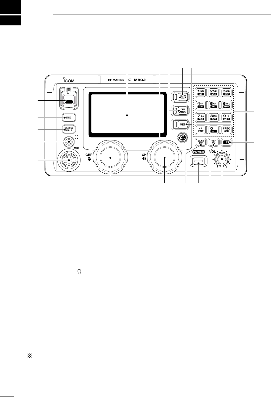
■Front panel— Controller
qDISTRESS SWITCH [DISTRESS] (p. 00)
Push for 5 sec. to make a distress call.
wDSC SWITCH [DSC]
➥Selects DSC function when pushed. (p. 00)
• Select DSC channel with [CH].
➥After pushing [F], print out the selected contents,
when a printer is connected. (p. 00)
eCANCEL/CALL SWITCH [CANCEL/CALL]
➥Cancels a distress call. (p. 00)
➥Push for 1 sec. to make a DSC call. (p. 00)
rHEADPHONE JACK [ ]
Accepts headphones.
• Output power: 5 mW with an 8 Ωload.
• When headphones are connected, the internal speaker
or connected external speaker does not function.
tMICROPHONE CONNECTOR [MIC]
Accepts the supplied or optional microphone or
handset.
• See p. 00 for appropriate microphones.
• See p. 00 for microphone connector information.
yGROUP CHANNEL SELECTOR [GRP] (p. 00)
Selects groups in 20 channel steps and ITU marine
channel groups.
NOTE: Some versions have no ITU channels.
uCHANNEL SELECTOR [CH] (p. 00)
➥Selects an operating channel within the selected
channel group such as ITU channels. (p. 00)
•User channels can be selected from 1 to 160 (max.)
in sequence regardless of the channel group.
➥Changes the operating frequency* after
[RX
CLAR
] is pushed (while “å” appears).
•The changed frequency is not programmed in this
way.
iRX/CLARITY SWITCH [RX
CLAR
] (p. 00)
➥Push to enable the receive frequency set with the
keypad or [CH] selector. (p. 00)
• While receive frequency set is enabled, “å” appears.
➥After pushing [F], turns clarity function ON and
OFF.
• [CH] selector is used for clarity control.
➥After pushing [DSC], shows received DSC mes-
sages.
•[GRP] selector is used for Distress and Individual call
selection.
• [CH] selector is used for message selection.
oPOWER SWITCH [POWER]
➥Push to turn the power ON.
➥Push for 1 sec. to turn the power OFF.
!0 TX/TRANSMIT FREQUENCY SWITCH [TX
TXF
]
(p. 00)
➥Push to enable the transmit frequency set with
the keypad. (p. 00)
• While transmit frequency set is enabled, “TX” blinks.
➥
After pushing [F], displays the transmit fre-
quency, and opens the squelch. Checks and mon-
itors the transmit frequency while holding. (p. 00)
DISTRESS
q
w
e
r
t
yuio!0 !1
!2
!3
!4!5!6!7Function display (p. 00)
*Some versions do not have frequency selection and fre-
quency indication.
3
2
PANEL DESCRIPTION
!1 VOLUME CONTROL [VOL] (p. 00)
Adjusts the audio output level.
•Audio does not come from the speaker when:
- A microphone is not connected.
- The speaker switch is turned ON.
- The squelch switch is turned ON and no signal is being
received.
!2 FUNCTION SWITCH [F] (p. 00)
After pushing, activates the secondary functions.
•“F” appears when when a secondary function can be
accessed.
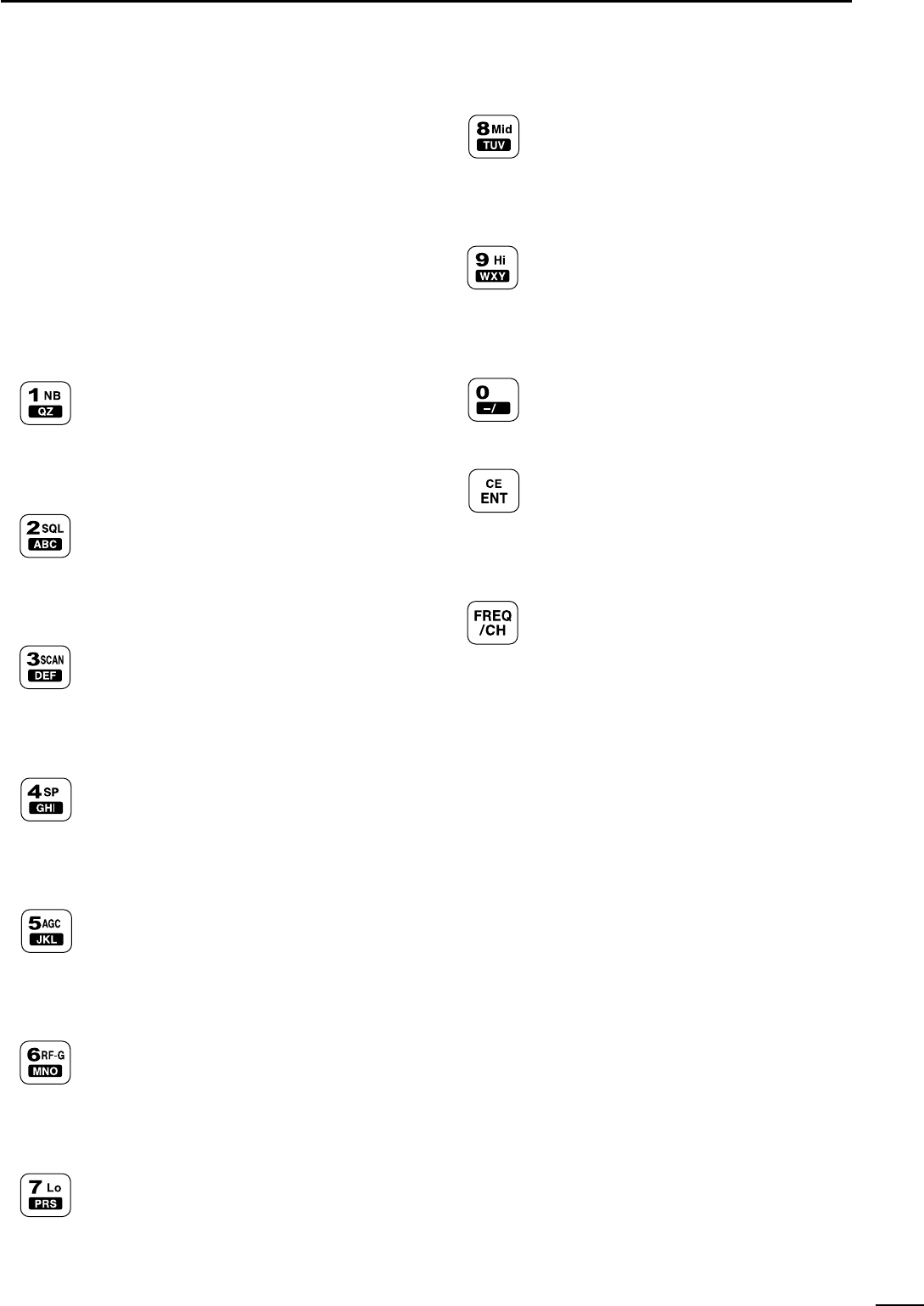
!3 KEYPAD (p. 00)
➥Input numeral “1” for channel number,
frequency input, etc.
➥Input “1,” “Q” or “Z” for channel comment
input.
➥After pushing [F], turns the noise
blanker function ON and OFF. (p. 00)
➥Input numeral “2” for channel number,
frequency input, etc.
➥Input “2,” “A,” “B” or “C” for channel com-
ment input.
➥After pushing [F], turns the voice or S-
meter squelch ON and OFF. (p. 00)
➥Input numeral “3” for channel number,
frequency input, etc.
➥Input “3,” “D,” “E” or “F” for channel com-
ment input.
➥After pushing [F], starts and stops the
scan function. (p. 00)
➥Input numeral “4” for channel number,
frequency input, etc.
➥Input “4,” “G,” “H” or “I” for channel com-
ment input.
➥After pushing [F], turns the speaker out-
put ON and OFF. (p. 00)
➥Input numeral “5” for channel number,
frequency input, etc.
➥Input “5,” “J,” “K” or “L” for channel com-
ment input.
➥After pushing [F], turns the AGC function
ON and OFF. (p. 00)
➥Input numeral “6” for channel number,
frequency input, etc.
➥Input “6,” “M,” “N” or “O” for channel com-
ment input.
➥After pushing [F], enters to the RF gain
adjustment mode. (p. 00)
➥Input numeral “7” for channel number,
frequency input, etc.
➥Input “7,” “P, ” “R” or “S” for channel com-
ment input.
➥After pushing [F], selects low transmit
output power. (p. 00)
➥Input numeral “8” for channel number,
frequency input, etc.
➥Input “8,” “T,” “U” or “V” for channel com-
ment input.
➥After pushing [F], selects middle trans-
mit output power. (p. 00)
➥Input numeral “9” for channel number,
frequency input, etc.
➥Input “9,” “W,” “X” or “Y” for channel com-
ment input.
➥After pushing [F], selects high transmit
output power. (p. 00)
➥Input numeral “0” for channel number,
frequency input, etc.
➥Input “0” and symbols (as follows) for
channel comment input.
➥Fixes input of channel number, frequency
and channel comment, etc.
➥When pushed for 1 sec., stores pro-
grammed frequency, operating mode and
memory comment into a channel.
➥After pushing [F], clears clarity setting.
➥Selects display type:
When channel comment indication is ON;
switches transmit frequency indication
ON and OFF
when channel comment indication is OFF;
switches channel comment indication
ON and OFF
➥After pushing [F], enters channel com-
ment programming mode, when channel
comment indication is ON.
!4 SET SWITCH [SET]
➥Enters quick set mode (p. 00)
➥After pushing [DSC], enters DSC set mode.
(p. 00)
!5 TUNE/THROUGH SWITCH [TUNE
THRU
] (p. 00)
➥Starts tuning when an optional antenna tuner is
connected.
•“TUNE” appears when tuned.
•When the tuner cannot tune the antenna, the tuning
circuit is bypassed automatically after 20 sec.
➥After pushing [F], bypasses an external antenna
tuner.
•“THROUGH” appears instead of “TUNE” indication.
!6 MODE/DIMMER SWITCH [MODE
DIM
](p. 00)
➥Push to select an operating mode.
•J3E, H3E, LSB, J2B, F1B and A1A modes are avail-
able, depending on version or countries.
➥After pushing [F], selects LCD backlight bright-
ness.
!7 E-MAIL SWITCH [e-mail] (p. 00)
➥Selects the operating frequencies, mode and fil-
ter setting for e-mail operation.
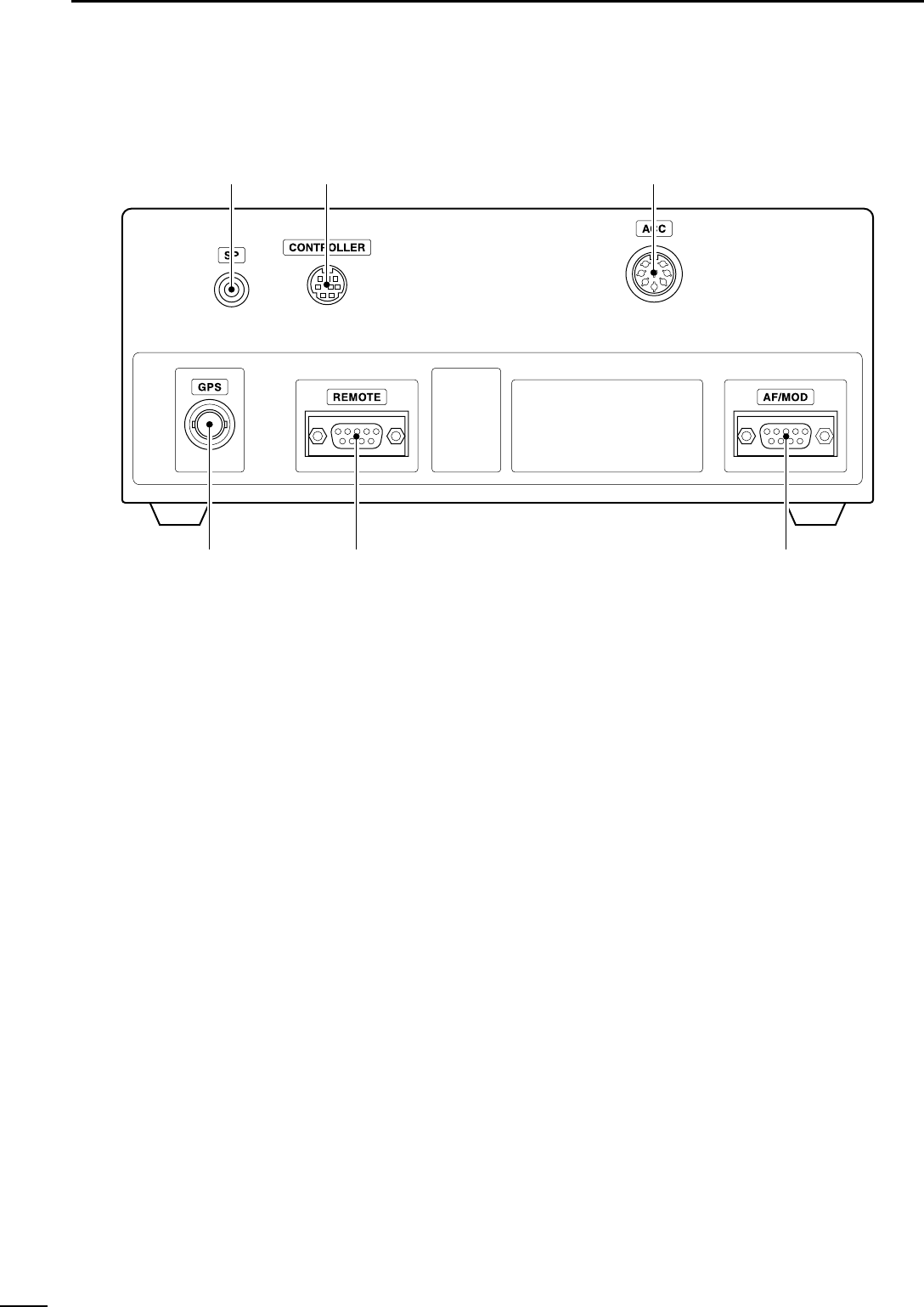
■Front panel— Main unit
qGPS CONNECTOR [GPS] (p. 00)
Connects a GPS receiver (NMEA0183 ver. 2.0) for
sending positioning data without manual input.
wREMOTE CONNECTOR [REMOTE] (p. 00)
Connects the IC-M802 to a PC via an RS-232C
cable (9-pin) for remote control of transceiver func-
tion in the NMEA format.
eAF/MOD CONNECTOR [AF/MOD] (p. 00)
Connects the IC-M802 to an NBDP system via an
RS-232C cable (9-pin).
rACC CONNECTOR [ACC] (p. 00)
Connects a CW keyer or an FSK terminal unit
tCONTROLLER CONNECTOR [CONTROLLER]
(p. 00)
Connects the supplied remote controller.
ySPEAKER JACK [SP] (p. 00)
Connects the supplied external speaker.
4
2PANEL DESCRIPTION
qw e
rty
5
2
PANEL DESCRIPTION
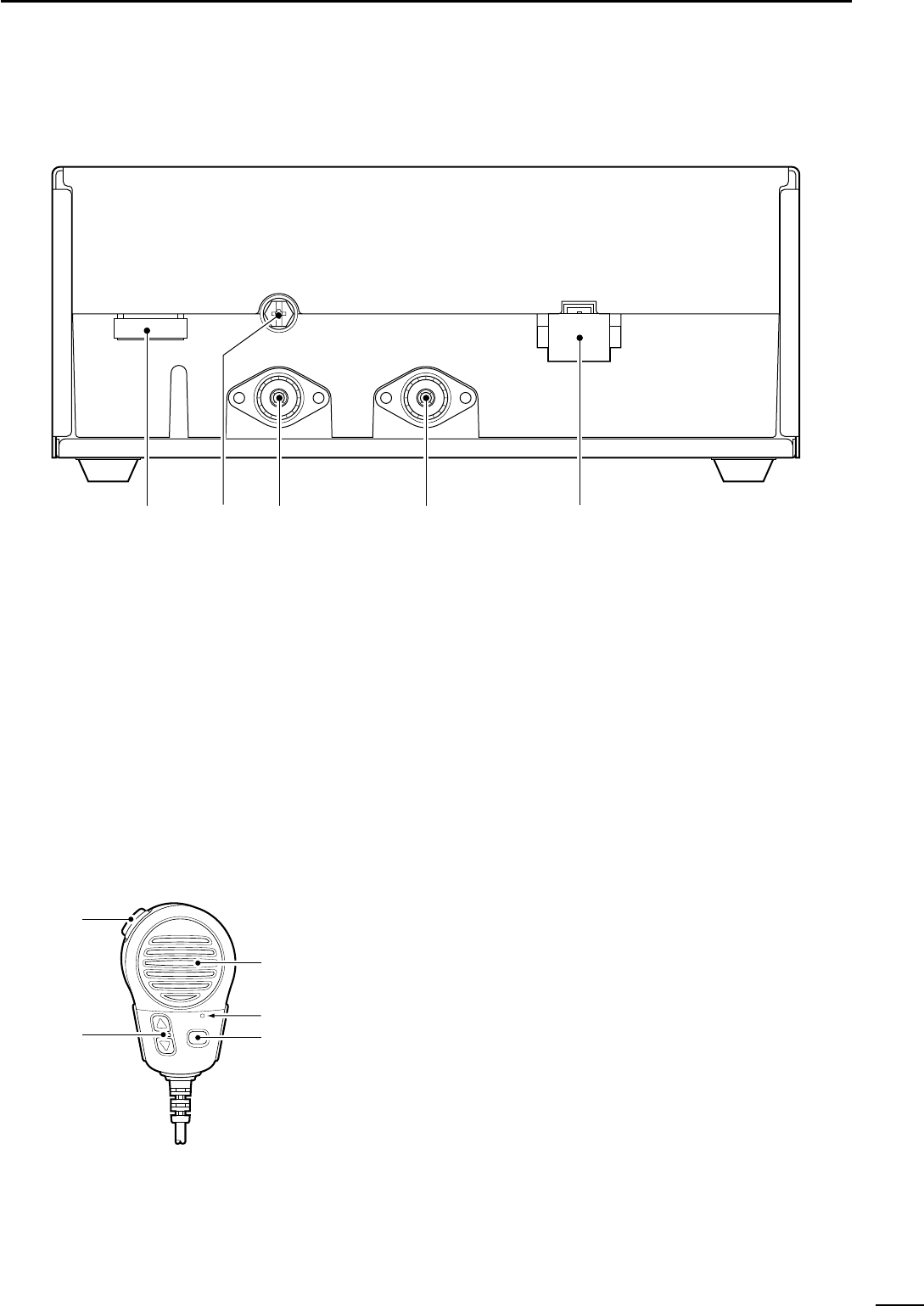
■Rear panel— Main unit
qTUNER CONTROL SOCKET (p. 00)
Connects a control cable to an optional antenna
tuner, AT-140, AT-130/E
ANTENNA TUNER
, A female
connector is supplied for connection.
w
GROUND TERMINAL (p. 00)
IMPORTANT! Connects a vessel's (or vehicle's)
ground. See p. 00 for details.
eANTENNA CONNECTOR 1 (p. 00)
Connects a 50 ΩHF band antenna with a 50 Ω
matched coaxial cable and a PL-259 plug for both
transmit and receive operation.
rANTENNA CONNECTOR 2 (p. 00)
Connects a 50 ΩHF band antenna with a 50 Ω
matched coaxial cable and a PL-259 plug for DSC
receive operation only.
tDC POWER SOCKET (p. 00)
Accepts 13.6 V DC through the supplied DC power
cable.
qwe r t
■Microphone (HM-135)
qPTT SWITCH [PTT]
Push and hold to transmit; release to receive.
wUP/DOWN SWITCHES [∫∫]/[√√](p. 00)
Push either switch to change the operating channel,
set mode contents, etc.
eUSER PROGRAMMABLE SWITCH [P] (p. 00)
Push to activate or deactivate a function, selected
in set mode (p. 00).
Speaker
Microphone
w
q
e
qRECEIVE INDICATOR
“RX” appears when signals are received or the
squelch is open.
wTUNE INDICATOR (p. 00)
“TUNE” blinks while tuning, if an optional external
antenna tuner is connected.
•“TUNE” appears after tuning is completed and the tuner
is ON when AH-3 is connected.
e
OPERATING MODE INDICATOR (p. 00)
Shows the selected operating mode.
•“J3E,” “H3E,” “LSB,” “J2B,” “F1B” or “A1A” appears
depending on version.
rSIMPLEX/DUPLEX INDICATOR (p. 00)
“SIMP” appears when a simplex channel, “DUP”
appears when a duplex channel is selected.
tCLARITY INDICATOR (p. 00)
“CLAR” appears when the clarity function is acti-
vated and shows shifting frequency in Hz.
yCHANNEL NAME INDICATION
Shows the programmed channel names.
•Shows the programmed receive frequency when no
channel names are programmed.
uCHANNEL NUMBER INDICATION
Shows the selected channel number.
iSPEAKER OFF INDICATOR (p. 00)
“” appears when the speaker output is turned
OFF.
oAGC OFF INDICATOR (p. 00)
“” appears when the AGC is turned OFF.
!0 DSC WATCH INDICATOR (p. 00)
“DSC Watch” appears while the DSC receiver is
activated.
!1 NOISE BLANKER INDICATOR (p. 00)
“NB” appears when the noise blanker function is ac-
tivated.
!2 SQUELCH INDICATOR (p. 00)
“SQL” appears when the squelch is open.
!3 S/RF INDICATOR (p. 00)
Shows relative transmit output power levels during
transmit and receiving signal strength during re-
ceive.
!4 GPS INDICATOR (p. 00)
Shows position and UTC time when a GPS receiver
is connected. The indication is up dated each time
new GPS data is received.
•If no GPS receiver is connected, the position and UTC
time must be set in advance.
!5 TRANSMIT INDICATOR (p. 00)
➥“TX” appears during transmit.
➥“TX” blinks when setting a transmit frequency or
during cross channel operation.
!6 RECEIVE FREQUENCY READOUT (p. 00)
Shows receive frequency.
!7 TRANSMIT FREQUENCY READOUT (p. 00)
Shows transmit frequency.
!8 RECEIVE FREQUENCY SELECT MODE
INDICATOR (p. 00)
“å” appears while in receive frequency select mode.
!9 CURSOR (p. 00)
Shows the changeable receive frequency digit.
•The cursor moves by rotating the [GRP] selector while
in receive frequency select mode.
AGC
SP
6
2PANEL DESCRIPTION
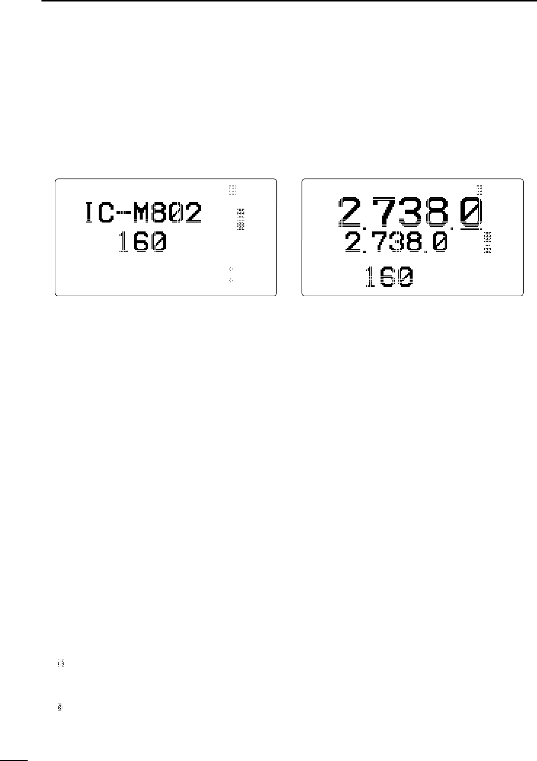
■LCD screen
The IC-M802 has 2 display types, one is channel
name indication and other one is frequency indication.
These display types can be switched with a push of a
button, depending on versions and set modes setting.
See p. 00 and p. 00 for display type settings.
• Channel name indication • Frequency indication
NB
LH
CH
CLAR
0
SP
AGC
DSC
Watch
---GPS---
UTC
16:23
Lat
45
59'N
Lon134
44'E
RX TUNE J3E SIMP NB
C
H
CLAR
0
SP
AGC
UTC
16:23
RX TUNEå J3E SIMP
3
7
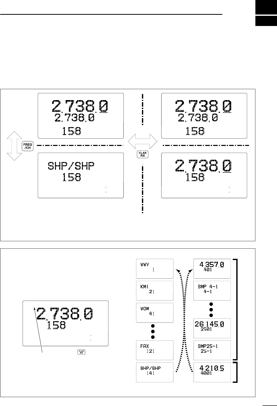
SELECTING A CHANNEL/FREQUENCY
■Selecting a channel
The transceiver as 160 user channels and ITU chan-
nels. However, the number of user channels can be
optionally restricted and ITU channels are not available
with some versions.
☞NOTE: When Channel 0 or 2182 kHz is selected
with the [2182kHz] switch, channel selection is NOT
possible. In such case, push [2182kHz] in advance.
☞NOTE: Channel name (alphanumeric) may not ap-
pear during channel indication depending on set
mode setting.
C
HUTC
16:23
RXå J3E SIMP
C
HUTC
16:23
RX J3E SIMP
CH
DSC
Watch
---GPS---
UTC
16:23
Lat
45
59'N
Lon134
44'E
RXå J3E SIMP
LH
CH
DSC
Watch
---GPS---
UTC
16:23
Lat
45
59'N
Lon134
44'E
RX J3E SIMP
LH
CHANNEL
indication
FREQUENCY
indication
CHANNEL SELECTION MODE
channel can be selected
FREQUENCY SELECTION MODE
frequency can be changed
DDUsing the channel selector
The transceiver has two large controls for group se-
lection and channel selection. The [GRP] selector
changes channels in 20 channel increments and se-
lects ITU channel groups*; and the [CH] selector se-
lects each channel.
qMake sure no “å” indicator appears in the display.
wRotate [GRP] selector to select the desired chan-
nel group as shown at right and/or below.
eRotate [CH] selector to select the desired channel.
[EXAMPLE]: Selection with the [GRP] selector
*All ITU channels are not available with some versions and
ITU FSK channels can be hidden using set mode (p 00).
ITU SSB channels*ITU FSK
channels*
CH
DSC
Watch
---GPS---
UTC
16:23
Lat
45
59'N
Lon134
44'E
RX J3E SIMP
LH
CH
DSC
Watch
---GPS---
UTC
16:23
Lat
45
59'N
Lon134
44'E
RX J3E SIMP
LH
CH
DSC
Watch
---GPS---
UTC
16:23
Lat
45
59'N
Lon134
44'E
RX J3E SIMP
LH
CH
DSC
Watch
---GPS---
UTC
16:23
Lat
45
59'N
Lon134
44'E
RX J3E SIMP
LH
CH
DSC
Watch
---GPS---
UTC
16:23
Lat
45
59'N
Lon134
44'E
RX J3E SIMP
LH
CH
DSC
Watch
---GPS---
UTC
16:23
Lat
45
59'N
Lon134
44'E
RX J3E DUP
LH
CH
DSC
Watch
---GPS---
UTC
16:23
Lat
45
59'N
Lon134
44'E
RX J3E SIMP
LH
CH
DSC
Watch
---GPS---
UTC
16:23
Lat
45
59'N
Lon134
44'E
RX J3E DUP
LH
CH
DSC
Watch
---GPS---
UTC
16:23
Lat
45
59'N
Lon134
44'E
RX J3E SIMP
å
LH
CH
DSC
Watch
---GPS---
UTC
16:23
Lat
45
59'N
Lon134
44'E
RX F1B DUP
LH
CH
DSC
Watch
---GPS---
UTC
16:23
Lat
45
59'N
Lon134
44'E
RX J3E SIMP
å
LH
If appears, push to delete it.
8
3SELECTING A CHANNEL/FREQUENCY
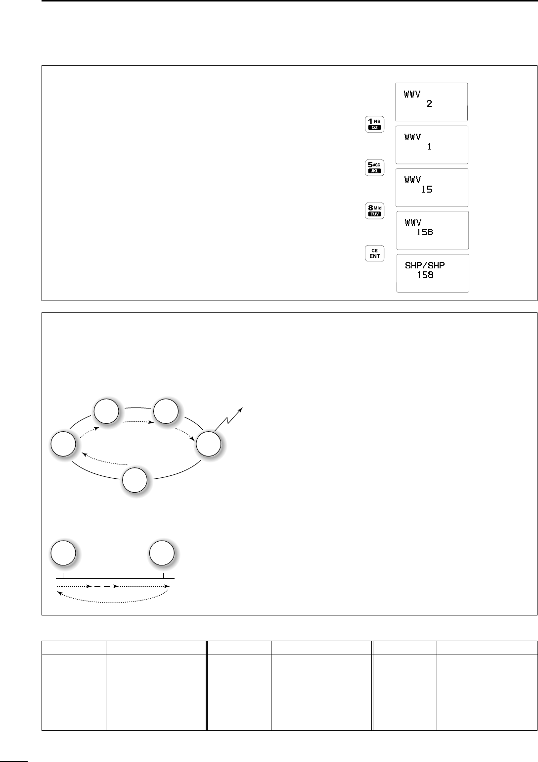
DDUsing the keypad
Direct channel selection via the keypad is available
for quick channel selection.
qMake sure no “å” indicator appears in the display.
•If it appears, push [RX
CLAR
] to delete it.
wEnter the desired channel number via the keypad.
•A user channel is selected when channel 1–160 is
input (max. number may be optionally restricted).
•An ITU SSB channel is selected when channel num-
bers higher than 401 are input (not available for some
versions).
•An ITU FSK channel is selected when channel num-
bers higher than 4001 are input (not usable according
to set mode setting).
•When selecting an ITU simplex channel, push [0] three
times instead of the “–” input.
(e.g. When selecting the channel 4-1;
— push [4
SP
], [0], [0], [0] then [1
NB
].)
ePush [ENT
CE
] to select the channel.
[EXAMPLE]: Selecting channel 158
LH
CH
DSC
Watch
---GPS---
UTC
16:23
Lat
45
59'N
Lon134
44'E
RX J3E
CH
DSC
Watch
---GPS---
UTC
16:23
Lat
45
59'N
Lon134
44'E
RX J3E
CH
DSC
Watch
---GPS---
UTC
16:23
Lat
45
59'N
Lon134
44'E
RX J3E
CH
DSC
Watch
---GPS---
UTC
16:23
Lat
45
59'N
Lon134
44'E
RX J3E
CH
DSC
Watch
---GPS---
UTC
16:23
Lat
45
59'N
Lon134
44'E
RX J3E SIMP
LH
LH
LH
LH
CHANNEL GROUPS
*1[GRP] selector changes in 20 channels steps. *2SITOR use— no group separation.
Channel No. Description Channel No. Description Channel No. Description
1 to 160 User ch.*18-1 to 8-9 8 MHz ITU simplex ch. 18-1 to 18-9 18 MHz ITU simplex ch.
401 to 427 4 MHz ITU duplex ch. 1201 to 1241 12 MHz ITU duplex ch. 2201 to 2253 22 MHz ITU duplex ch.
4-1 to 4-9 4 MHz ITU simplex ch. 12-1 to 12-9 12 MHz ITU simplex ch. 22-1 to 22-9 22 MHz ITU simplex ch.
601 to 608 6 MHz ITU duplex ch. 1601 to 1656 16 MHz ITU duplex ch. 2501 to 2510 25 MHz ITU duplex ch.
6-1 to 6-9 6 MHz ITU simplex ch. 16-1 to 16-9 16 MHz ITU simplex ch. 25-1 to 25-9 25 MHz ITU simplex ch.
801 to 832 8 MHz ITU duplex ch. 1801 to 1815 18 MHz ITU duplex ch. 4001 to 25040 ITU FSK duplex ch.*2
DDUsing scan function
(some versions do not have these functions)
The transceiver has automatic channel or frequency
change capability (scan function). There are 3 types
of scan functions available to suit your needs.
Channel scan and channel resume scan increase
channels within a 5 channel range such as Ch 1 to
Ch 5, Ch 156 to Ch 160, etc. in user channels; or all
channels in the group of ITU channels.
Programmed scan (optional) scans frequencies
within the frequency range between user channels
159 and 160.
Scan selection is available in set mode. See p. 00 for
scan selection.
SCAN OPERATION
qRotate [GRP] and [CH] selectors to select your de-
sired channel group.
•Or use the keypad and [
CE
ENT] for direct selection.
•This operation is not necessary for programmed scan.
wPush [F] then [2
SQL
] to turn OFF the squelch
function, if programmed scan is selected.
•A user channel is selected when channel 1–160 is
input (max. number may be optionally restricted).
ePush [F] then [3
SCAN
] to start the scan.
rTo stop the scan, repeat step eagain.
•Pushing other switches also stops the scan.
Channel scan/Channel resume scan
ch 1
ch 2 ch 3
ch 4
ch 5
When resume OFF;
scan is cancelled whe
transmitting
When resume ON;
scan pauses for 30 sec
then resumes afte
transmitting
Programmed scan (optional)
ch 159 ch 160
Scans the frequency rang
between the programme
frequencies on channel
159 and 160.
Scans fast when squelch i
closed and slowly whe
squelch is open.
3
9
SELECTING A CHANNEL/FREQUENCY
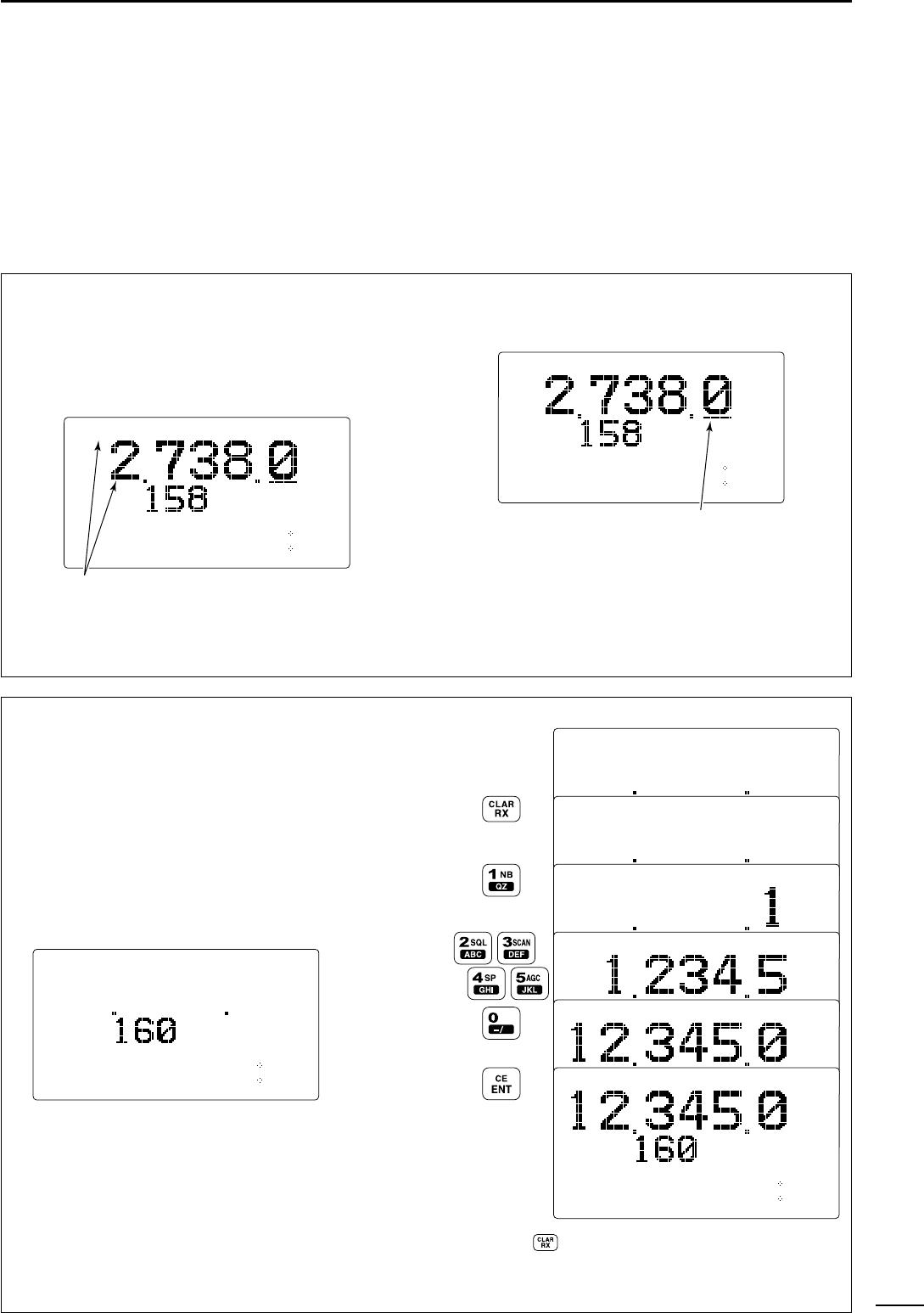
■Selecting a frequency
The transceiver has 0.5 to 30.0 MHz general coverage
receive capability with 1 Hz resolution. The receive
frequency can be changed instantly, independent of
the transmit frequency.
☞NOTE: The selected frequency is used for
temporary receiving (transmitting is not available).
This frequency is cleared once the channel is
changed. If you want to program a frequency refer
to p. 00.
DDUsing the channel selector
qSelect a channel which is programmed near the
frequency you want to receive.
wPush [RX
CLAR
] to select frequency selection
mode.
•“å” appears in the display.
eRotate [GRP] selector to select the digit for tuning.
•Under-bar shows the selected digit.
☞The under-bar is not displayed when 10 or 1 Hz dig-
its are selected during frqeuency indication.
rRotate [CH] selector to tune the frequency.
tTo return to the previous frequency, push
[RX
CLAR
].
•“å” disappears.
CH
DSC
Watch
---GPS---
UTC
16:23
Lat
45
59'N
Lon134
44'E
RXå J3E SIMP
LH
The under-bar is moved with [GRP] rotaion.
CH
DSC
Watch
---GPS---
UTC
16:23
Lat
45
59'N
Lon134
44'E
RXå J3E SIMP
LH
“å” and frequency show that the
frequency can be changed.
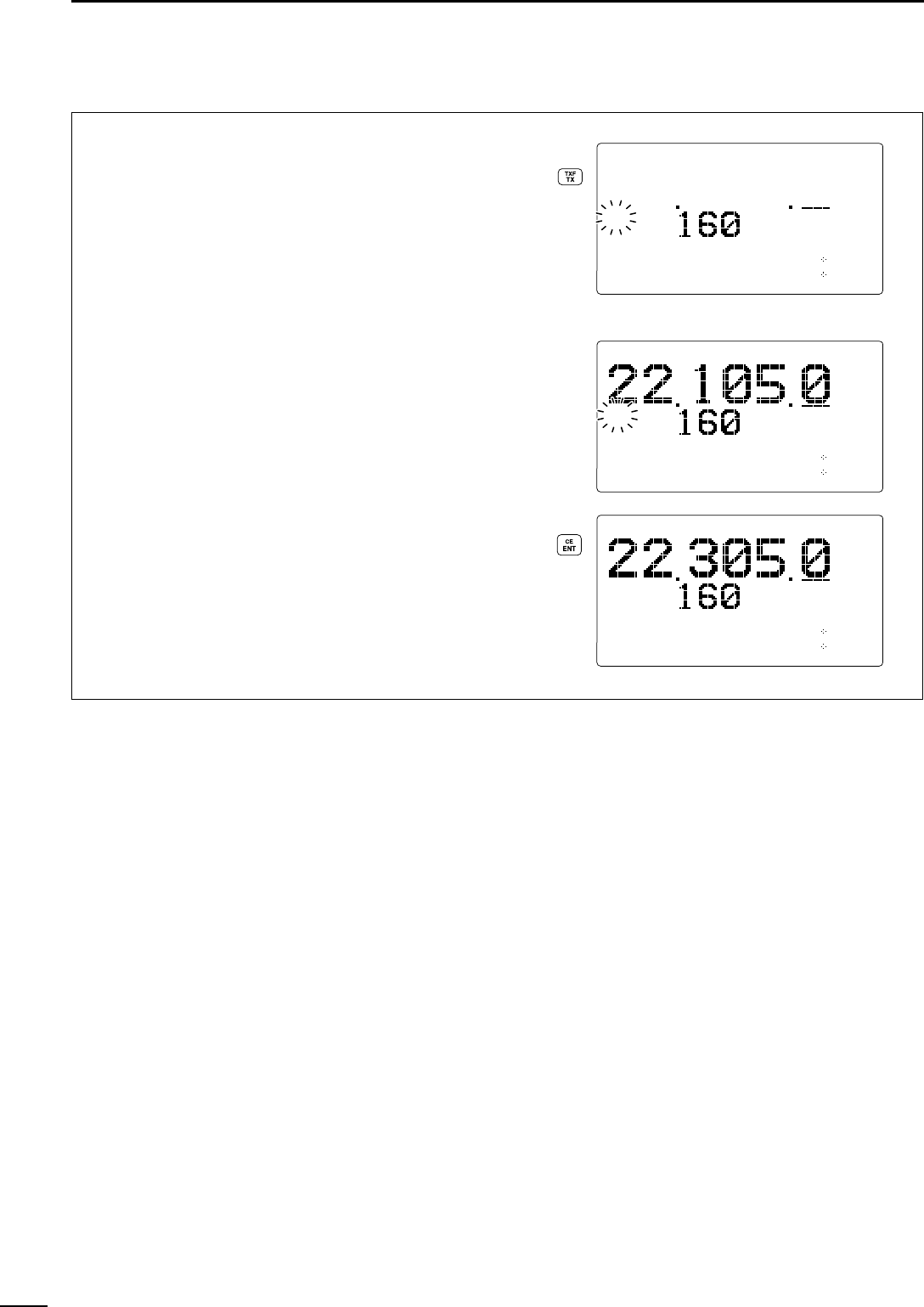
DDUsing the keypad
☞CAUTION: A frequency can be entered into a user
channel or ITU simplex channel by pushing
[RX
CLAR
] after entering a frequency. The previ-
ously programmed contents are erased and can-
not be retrieved. Therefore, keypad entry should
be used only on spare channels.
qRotate [GRP] and [CH], or enter a 1 to 4 digit num-
ber via the keypad, then push [ENT
CE
] to select
the memory channel to be used for general cover-
age use.
When no frequency programmed channel is selected, op-
erating frequency, mode and channel name do not appear.
wPush [RX
CLAR
] to select frequency selection
mode.
•“å” appears in the display.
eEnter 4 to 6 digits of the desired frequency via the
keypad.
rPush [ENT
CE
] to input the frequency.
•
DO NOT hold [ENT
CE
] for more than 1 sec., otherwise
the frequency will be programmed into the channel.
[EXAMPLE]: Setting 12.3450 MHz
å
å
å
å
RXå J3E
CH
DSC
Watch
---GPS---
UTC
16:23
Lat
45
59'N
Lon134
44'E
LH
Select no frqeu-
ency program-
med channel
When push then rotate [CH] to re-select the channel,
the set frequency will be cleared.
LH
CH
DSC
Watch
---GPS---
UTC
16:23
Lat
45
59'N
Lon134
44'E
4
10
RECEIVE AND TRANSMIT
■Basic voice transmit and receive
qCheck the following in advance.
➥Microphone or handset is connected.
➥No “SQL” indication.
•If “SQL” appears, push [F] then [2
SQL
] to turn the
squelch OFF.
➥No “” indication.
•If “” appears, push [F] then [4
SP
] to activate the
speaker.
➥The clarity function is not activated.
•Push [F] then [RX
CLAR
] to turn the clarity function
OFF.
wRotate [GRP] and [CH] selectors to select the de-
sired channel to be received.
•When receiving a signal, the S-meter shows the signal
strength.
eAdjust [VOL] to the desired audio level when re-
ceiving a signal.
rPush [MODE
DIM
] to select the desired operating
mode.
tPush [TUNE
THRU
] to tune the antenna tuner, if con-
nected.
•This operation is not necessary when “automatic tuning”
is selected in set mode (p. 00).
yTo transmit on the channel, push and hold the PTT
switch on the microphone (or handset).
•“TUNE” blinks for 1 to 2 sec. for the first transmission
on a channel when an antenna tuner is connected.
uAfter the blinking stops, speak into the microphone
at your normal voice level.
•The RF meter shows the output power according to your
voice level.
iRelease the PTT switch to return to receive.
[RX CLAR]Microphone
connector
[4 SP] [2 SQL]
[F]
SP
SP
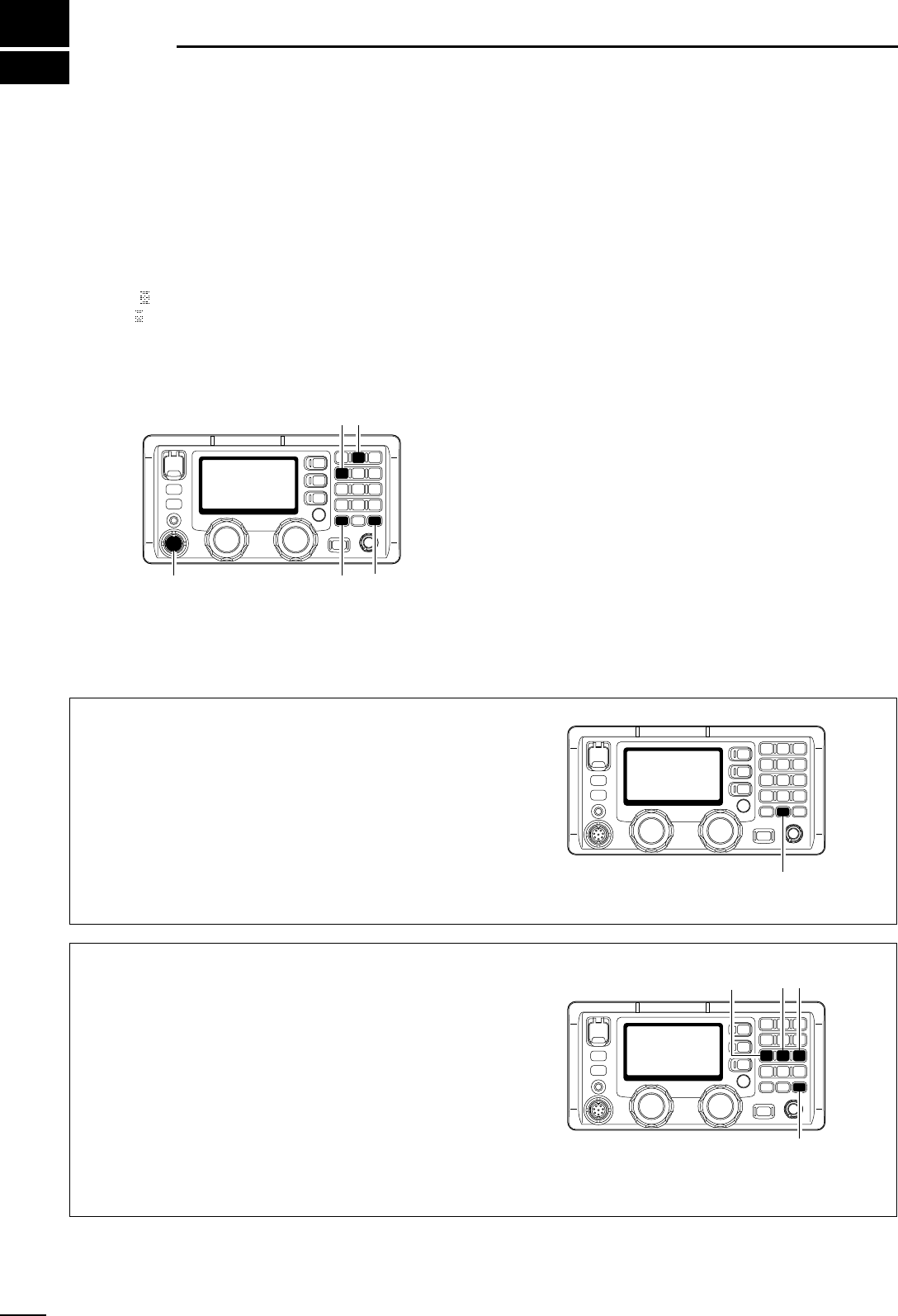
■Functions for transmit
DDTransmit frequency check
When “DUP” appears in the display such as for a
ship-to-ship channel, the transmit frequency differs
from the receive frequency.
In such cases, the transmit frequency should be mon-
itored before transmitting to prevent interference to
other stations.
➥Push and hold [TX
TXF
] to monitor the transmit fre-
quency. •The display shows the transmit frequency.
[TX TXF]
DDTransmit power selection
The transceiver has 3 selectable power output lev-
els.* High power allows linger distance communica-
tions and low power reduces power consumption.
*Only 2 selectable output power levels are available with
some versions. In this case, low stands for 60 W (the same
as middle).
qPush [F] first.
•“F” appears.
wPush one of [7
Lo
], [8
Mid
] or [9
Hi
] to select low,
middle or high output power levels, respectively.
•The display shows the selected output power level for
approx. 2 sec., then returns to the previous indication.
☞NOTE: Low power setting affects all channels ex-
cept the 2182 kHz emergency channel.
[F]
[9 Hi][8 Mid][7 Lo]
11
4
RECEIVE AND TRANSMIT
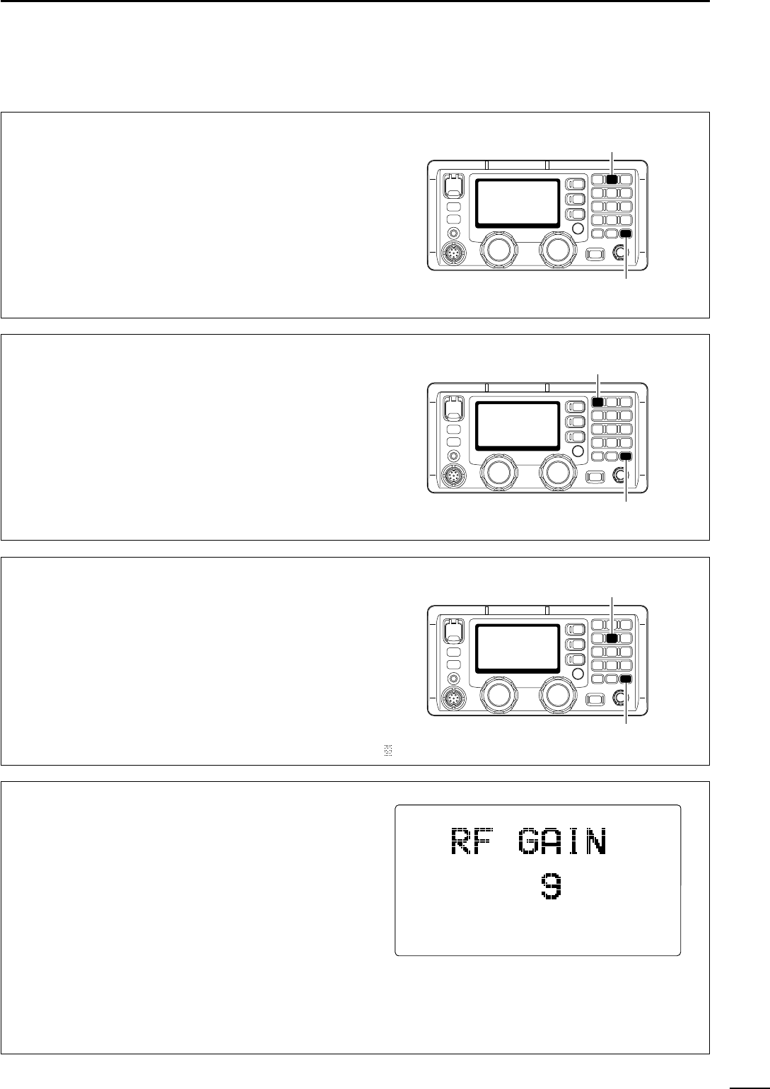
■Functions for receive
DDSquelch function
The squelch function detects signals with voice com-
ponents and squelches (mutes) unwanted signals
such as unmodulated beat signals. This provides
quiet stand-by.
When you need to receive weak signals, the squelch
should be turned OFF.
➥Push [F] then [2
SQL
] to switch the function ON
and OFF.
•“SQL” appears when the squelch function is turned ON.
[2 SQL]
[F]
DDNoise blanker
The noise blanker function reduces pulse type noise
such as that coming from engine ignitions, etc.
The noise blanker may distort reception of strong sig-
nals. In such cases, the noise blanker should be
turned OFF.
➥Push [F] then [1
NB
] to switch the function ON and
OFF.
•“NB” appears when the squelch function is turned ON.
[1 NB]
[F]
DDAGC OFF function
The receive gain is automatically adjusted according
to received signal strength with the AGC (Automatic
Gain Control) function to prevent distortion from
strong signals and to obtain a constant output level.
When receiving weak signals with adjacent strong
signals or noise, the AGC function may reduce the
sensitivity. In this situation, the AGC function should
be deactivated.
➥Push [F] then [5
AGC
] to switch the function ON
and OFF. •“ ” appears when the squelch function is turned OFF.
AGC
[5 AGC]
[F]
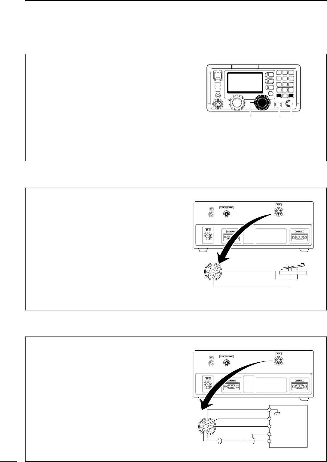
DDRF gain setting
The receiver gain can be reduced with the RF gain
setting. This may help to remove undesired weak sig-
nals while monitoring strong signals.
Usually, the AGC function reduces the RF gain ac-
cording to the receive signal strength and these weak
signals are removed. However, during no signal re-
ception, these weak signals may not be heard.
In such cases, the RF gain may be useful for setting a
minimum level at which to hear signals.
qPush [F] then [6
RF
-
G
] to select the RF gain set
mode, as shown at right.
wRotate [CH] selector to set the desired minimum
cutting level.
•“0” to “9” are available.
•S-meter shows the minimum permitted level.
ePush [SET] to exit the RF gain set mode.
DDClarity control
Voice signals received from other stations may be dif-
ficult to receive. This may sometimes happen if a sta-
tion is transmitting slightly off frequency. In such
cases, you can compensate by using the clarity con-
trol.
When receiving weak signals with adjacent strong
signals or noise, the AGC function may reduce the
sensitivity. In this situation, the AGC function should
be deactivated.
qPush [F] then [RX
CLAR
] to switch the function ON
and OFF.
•“CLAR” and shifting value appear
wRotate [CH] to improve the audio readability.
•Adjustable between ±150 Hz in 10 Hz steps.
[RX CLAR][CH] [F]
■Functions for receive (continued)
■CW operation
12
4RECEIVE AND TRANSMIT
The transceiver has the following CW keying features
selectable in set mode as described on p. 00.
➥Full break-in (receiving is possible while transmitting)
➥Semi break-in (automatic transmission with keying)
➥OFF (manual transmission is necessary before keying)
qConnect a CW keyer or an external electronic
keyer to the [ACC] socket as shown at right.
wSelect the desired channel to operate CW mode.
eWhen the selected channel is not in A1A mode,
push [MODE
DIM
] several times to select “A1A.”
rOperate the CW keyer to transmit a CW signal.
☞NOTE: CW mode is not available in some versions
and CW narrow can be selected in set mode (p. 00)
when an optional filter is installed (already built-in
to the GMDSS version).
CW key connection
1
2
3
4
5
6
7
8To pin 1
To pin 2
■FSK operation
The transceiver has FSK and J2B modes for FSK op-
eration— use F1B when using the built-in oscillator;
use J2B when using an AFSK terminal unit.
qConnect an FSK terminal unit to the [ACC] socket
as shown at right.
wSelect the desired channel to operate FSK mode.
•FSK ITU channel group, Ch 4001 to Ch 2540, are avail-
able depending on version.
e
Push [MODE
DIM
] several times to select F1B or J2B.
rOperate the FSK terminal unit.
☞NOTE:
➥FSK shift frequency and FSK polarity can be ad-
justed in set mode (p. 00)
➥Some transceivers may operate 1.7 kHz higher
than the IC-M802’s J2B mode even when the same
displayed frequencies are in use.
FSK terminal unit connection
1
2
3
4
5
6
7
8To pin 1
To pin 3
FSK keying
AF input
FSK terminal unit
AF ground
Tx/Rx control
Ground
To pins 2, 5

5
13
USER CHANNEL PROGRAMMING
■Programming a frequency
The IC-M802 has up to 160 user-programmable chan-
nels each with channel name capability of up to 8 al-
phanumeric characters.
☞NOTE: ITU simplex channels can be programmed
as well as user channels. However, transmit fre-
quencies cannot be programmed as it is not neces-
sary.
DDReceive frequency
qSelect the desired channel to be programmed.
•Channel 1 to 160 (maximum) are programmable.
wPush [RX
CLAR
] to select frequency selection
mode.
•“Ç” and frequency appear in the display.
eEnter the desired frequency via the keypad— 5 or
6 digits.
•Or rotate [GRP] and [CH] selectors to change the fre-
quency.
rPush [MODE
DIM
] several times to select the de-
sired operating mode (type of emission).
tPush [ENT
CE
] for 1 sec. to program the user
channel.
•3 beeps sound.
•“Ç” and frequency disappear from the display.
CH
DSC
Watch
---GPS---
UTC
16:23
Lat
45
59'N
Lon134
44'E
RXå J3E
LH
CH
DSC
Watch
---GPS---
UTC
16:23
Lat
45
59'N
Lon134
44'E
RXå J3E
LH
CH
DSC
Watch
---GPS---
UTC
16:23
Lat
45
59'N
Lon134
44'E
RX J3E
LH
Push
Push
for 1 sec.
Set
frequency
“
å
” indicator blinks.
Use keypad or channel selector.
Programming is completed.
DUP
DUP
DUP
DDChannel names
qSelect the desired channel to be programmed.
wPush [FREQ/CH] to select channel indication
mode, if desired.
wPush [F] then [FREQ/CH].
•The 1st character for the channel names blinks.
rRotate [CH] selector to select the character of
channel names and push keypad several times to
enter that character.
tPush [ENT
CE
] to program the channel name.
CH
DSC
Watch
---GPS---
UTC
16:23
Lat
45
59'N
Lon134
44'E
RX J3E DUP
LH
CH
DSC
Watch
---GPS---
UTC
16:23
Lat
45
59'N
Lon134
44'E
RX J3E DUP
LH
CH
DSC
Watch
---GPS---
UTC
16:23
Lat
45
59'N
Lon134
44'E
RX J3E DUP
LH
Rotate [CH] to
select character
and push key-
pad to enter
that character.
Push
then
Push
14
5USER CHANNEL PROGRAMMING
DDTransmit frequency
(Not applicable for General versions)
qSelect the desired channel to be programmed.
wPush [TX
TXF
]
•“TX” blinks.
eEnter the desired frequency via the keypad with 5
or 6 digits.
•[GRP] and [CH] selectors cannot be used.
rPush [MODE
DIM
] several times to select the de-
sired operating mode (type of emission).
tPush [ENT
CE
] for 1 sec. to program the user
channel.
•3 beeps sound.
CH
TX
TX
DSC
Watch
---GPS---
UTC
16:23
Lat
45
59'N
Lon134
44'E
RX J3E
LH
CH
DSC
Watch
---GPS---
UTC
16:23
Lat
45
59'N
Lon134
44'E
RX J3E
LH
CH
DSC
Watch
---GPS---
UTC
16:23
Lat
45
59'N
Lon134
44'E
RX J3E
LH
Push
Push
for 1 sec.
Set
frequency
“
TX
” indicator blinks and shows transmit
frequency.
Use keypad.
Programming is completed.
DUP
DUP
DUP
6
15
SET MODE
■About set mode
Set mode operation is used for programming infre-
quently changed values or conditions of functions.
☞NOTE: Some of the set mode items described in this
selection are not available on some transceiver ver-
sions.
■General set mode
DDEntering general set mode
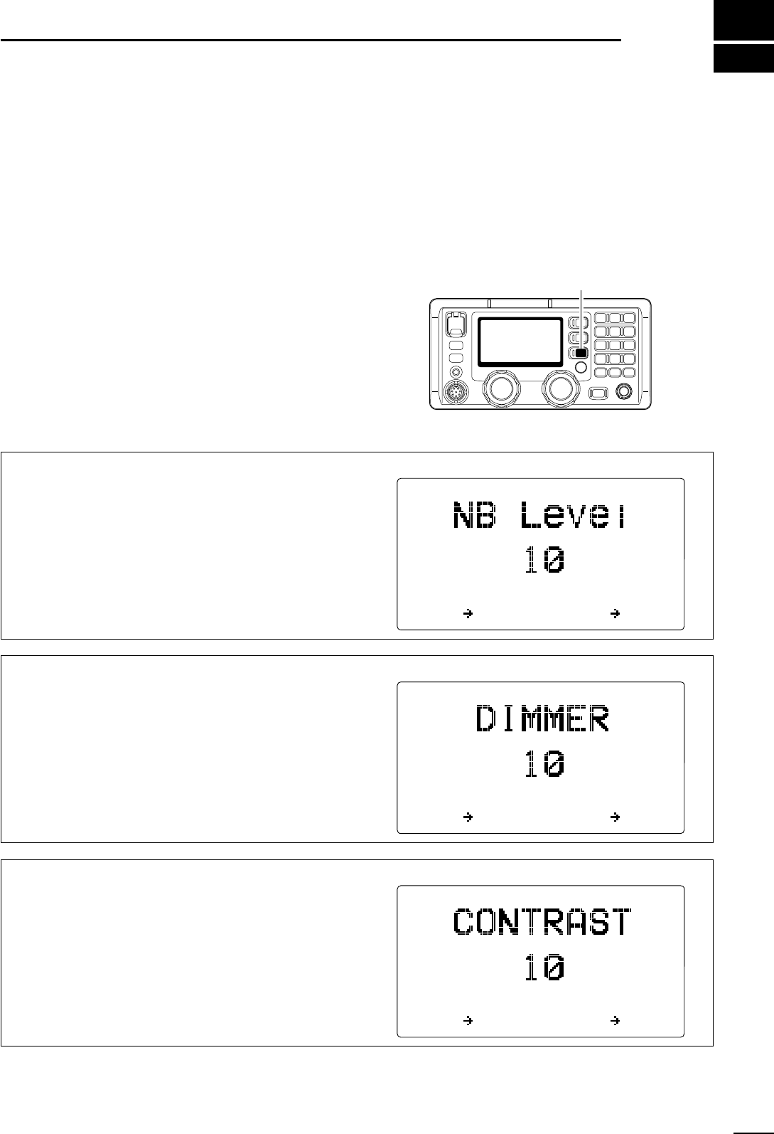
qPush [SET] to enter general set mode.
wRotate [GRP] to select the desired item.
eRotate [CH] to set the values or conditions for the
selected item.
rPush [SET] again to exit general set mode.
[SET]
Noise blanker level
This item adjusts the noise blanker level to protect a
signal from various pulse-type noises from 1 to 10.
(default: 10)
The set level is effective when the noise blanker is ac-
tivated.
GRP ITEM CH SEL
DDGeneral set mode items
Dimmer
This item sets the LCD back light brightness for dim-
mer selection from 0 (dark) to 10 (bright).
By pushing [F] then [MODE
DIM
], the set brightness
is selected to provide easy visibility during night time
operation, etc.
(default: 10)
GRP ITEM CH SEL
LCD contrast
This item sets the LCD contrast from 1 to 10.
GRP ITEM CH SEL
16
6SET MODE
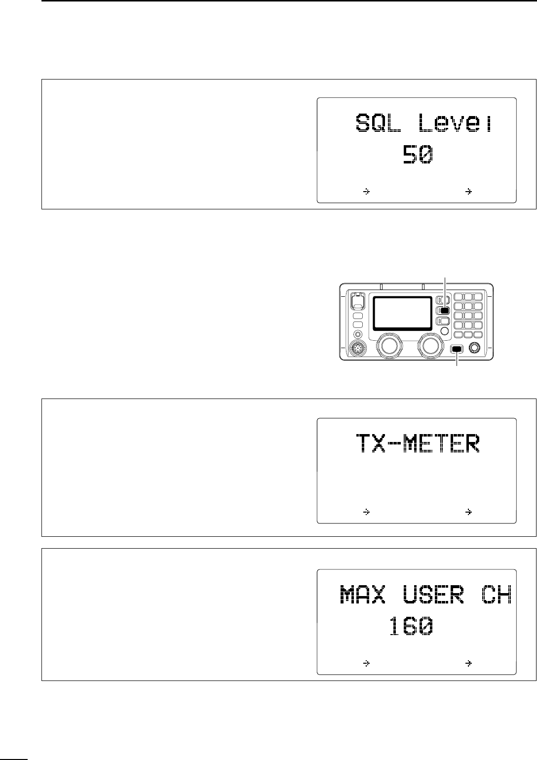
Squelch level
This item adjusts the squelch threshold level from 1
to 100.
(default: 50)
When the squelch is activated, signals stronger than
the this set level only are received.
GRP ITEM CH SEL
DDGeneral set mode items (continued)
■Set mode A
DDEntering set mode
qPush [POWER] for 1 sec. to turn the power OFF, if
necessary.
wWhile pushing [MODE
DIM
], push [POWER] to turn
the power ON and enter set mode.
eRotate [GRP] to select the desired item.
eRotate [CH] to set the values or conditions for the
selected item.
rTurn the power OFF and ON again to exit set mode.
DDSet mode A items
[MODE DIM]
[POWER]
Number of user channels
This item sets the number of user channels. Up to
160 channels can be set.
GRP
***
SET
MODE
A
***
ITEM CH SEL
Transmit meter
This item selects the transmit meter type from an-
tenna current and RF power.
•ANTENNA-CURRENT
: Shows driving current of the an-
tenna. (Can be selected when
an external antenna tuner is con-
nected.)
•RF-POWER : Shows relative output power.
(default)
GRP
***
SET
MODE
A
***
ANTENNA-CURRENT
RF-POWER
ÇÇ
ITEM CH SEL
DDSet mode A items (continued)
17
6
SET MODE
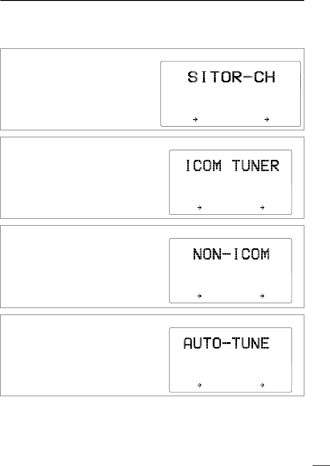
FSK ITU channel selection
This item sets the capability of the ITU channels for
FSK from ON and OFF.
This item will not appear when ITU channels are in-
hibited.
GRP
***
SET
MODE
A
***
ITEM CH SEL
ON
OFF
ÇÇ
External antenna tuner type
This item selects the connected Icom antenna tuner
type from AT-140, AT-130/E, AT-120/E and AH-3
•AT-140 : AT-140 is connected. (default)
•AT-130/E : AT-130/E is connected.
•AT-120/E : AT-120/E is connected.
•AH-3 : AH-3 is connected.
GRP
***
SET
MODE
A
***
AT-140
AT-130/E
AT-120/E
AH-3
ÇÇ
ITEM CH SEL
External antenna tuner type
This item selects the external antenna tuner control
signals (Start and Key) conditions for operation with
a non-Icom antenna tuner.
•START&KEY : Reverse both start and key sig-
nals.
•KEY : Reverse the KEY signal.
•START : Reverse the START signal.
•ICOM : Use Icom’s standard conditions
(default)
GRP
***
SET
MODE
A
***
START&KEY
START
KEY
ICOM
ÇÇ
ITEM CH SEL
Automatic tune
When an optional AT-130A, AT-130 or AT-130E auto-
matic antenna tuner is connected, tuning can be
started automatically without pushing [TUNE
THRU
],
for instant operation.
If manual tuning is required, this automatic operation
can be deactivated.
GRP
***
SET
MODE
A
***
ON
OFF
ÇÇ
ITEM CH SEL
18
6SET MODE
DDSet mode A items (continued)
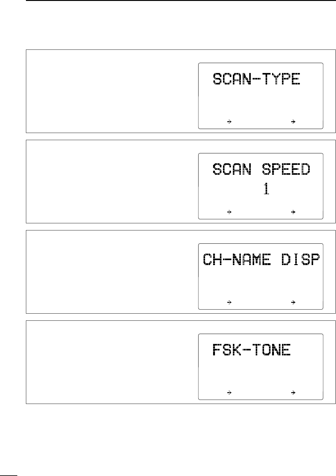
Scan type
This item selects one of the following scan functions.
Programmed scan (optional) searches signals within
the frequency range and activates slowly while
squelch is open and fast while squelch is closed.
Channel scan and channel resume scan searches 5
channels around a user selected channel, or
searches all ITU channels in the band when an ITU
channel is selected.
GRP
***
SET
MODE
A
***
PROGRAM
SCAN
CH-RESUME
SCAN
CH
SCAN
ÇÇ
ITEM CH SEL
Scan speed
This item adjusts the scan speed (rate at which chan-
nels are searched). The scan speed can be set from 1
to 10 with “1” being the fastest and “10” being the
slowest.
GRP
***
SET
MODE
A
***
ITEM CH SEL
Display type*
The upper half of the display can be set to display a
programmable channel name or a receive frequency
according to your needs.
*When the channel comment indication setting is OFF, this
item will not appear.
GRP
***
SET
MODE
A
***
CH-NAME
CH-FREQUENCY
ÇÇ
ITEM CH SEL
FSK tone frequency
Several mark frequencies are used for FSK operation.
This item selects an FSK mark frequency for almost
any FSK system from 1615 Hz, 1487.5 Hz, 1275 Hz
and 1200 Hz.
GRP
***
SET
MODE
A
***
1615Hz
1487.5Hz
1275Hz
1200Hz
ÇÇ
ITEM CH SEL
19
6
SET MODE
DDSet mode A items (continued)
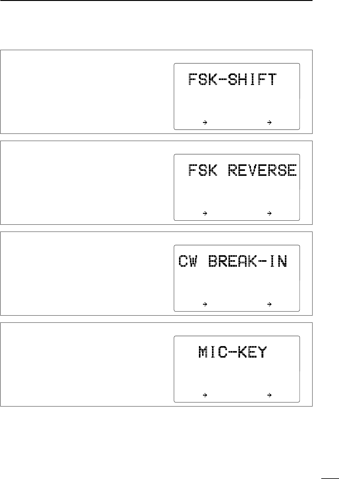
FSK shift frequency
Several shift frequencies are used for FSK operation.
This item selects an FSK shift frequency for almost
any FSK system from 850Hz, 425 Hz, 200 Hz and
170 Hz.
GRP
***
SET
MODE
A
***
850Hz
425Hz
200Hz
170Hz
ÇÇ
ITEM CH SEL
FSK polarity
Normal and reverse polarities are available for FSK
operations. This item allows you to select one of
these polarities.
•REVERSE : Key open=mark; Key close=space
•NORMAL : Key open=space; Key close=mark
GRP
***
SET
MODE
A
***
REVERSE
NORMAL
ÇÇ
ITEM CH SEL
CW break-in function
The CW break-in function (in A1A mode) toggles
transmit and receive with CW keying. Full break-in al-
lows you to receive signals between transmitted key-
ing pulses during CW transmission. Semi break-in al-
lows you to mute receiving until keying stops with
some delay time.
GRP
***
SET
MODE
A
***
FULL
DELAY
OFF
ÇÇ
ITEM CH SEL
Microphone keys
This item activates/deactivates the keys on the HM-
135
HAND MICROPHONE
(“P, ” “∫” and “√”). Refer to
p. 00 to program the [P] key.
GRP
***
SET
MODE
A
***
ON
OFF
ÇÇ
ITEM CH SEL
20
6SET MODE
DDSet mode A items (continued)
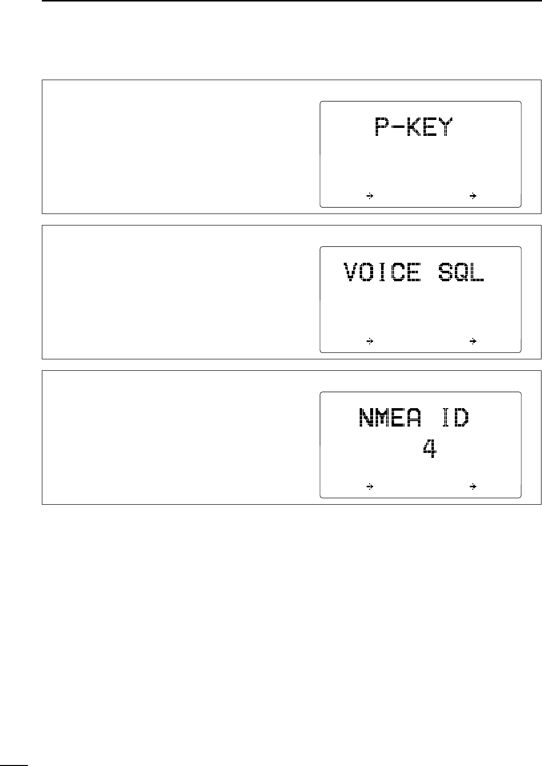
[P] key function
This item assigns a function to the [P] key on the HM-
135
HAND MICROPHONE
to activate it as the [2
SQL
],
[1
NB
], [MODE
DIM
] or [TUNE
THRU
] function.
GRP
***
SET
MODE
A
***
SQL
NB
MODE
TUNE
ÇÇ
ITEM CH SEL
Voice squelch
This item turns the voice squelch function ON and
OFF when operating in J3E and H3E modes.
When the function is set to OFF, the squelch acts as
an S-meter squelch for J3E and H3E modes.
GRP
***
SET
MODE
A
***
ON
OFF
ÇÇ
ITEM CH SEL
NMEA ID
This item selects the NMEA ID for the transceiver
from 1 to 99.
GRP
***
SET
MODE
A
***
ITEM CH SEL

1-1-32 Kamiminami, Hirano-ku, Osaka 547-0003 Japan
A-6????-1EX
Printed in Japan
© 2002 Icom Inc.
Icom America Inc.
<Corporate Headquarters>
2380 116th Avenue N.E., Bellevue, WA 98004, U.S.A.
Phone: (425) 454-8155 Fax: (425) 454-7619
URL: http//www.icomamerica.com
<Customer service>
Phone: (425) 454-7619
Icom (Europe) GmbH
Communication Equipment
Himmelgeister Str. 100,
D-40255 Düsseldorf, Germany
Phone: 0211 346047 Fax: 0211 333639
URL: http//www.icomeurope.com
Icom Canada
Glenwood Centre #150-6165 Highway 17, Delta,
B.C., V4K 5B8, Canada
Phone: (604) 952-4266 Fax: (604) 952-0090
URL: http//www.icomcanada.com
Icom Spain S.L.
Ctra. de Gracia a Manresa Km. 14,750 08190 Sant
Cugat del Valles Barcelona, SPAIN
Phone: (93) 590 26 70 Fax: (93) 589 04 46
URL: http//www.icomspain.com
Icom (Australia) Pty. Ltd.
A.C.N. 88 006 092 575
290–294 Albert Street, Brunswick, Victoria, 3056,
Australia
Phone: (03) 9387 0666 Fax: (03) 9387 0022
URL: http//www.icom.net.au
Icom (UK) Ltd.
Unit 9, Sea St., Herne Bay, Kent, CT6 8LD, U.K.
Phone: 01227 741741 Fax: 01227 741742
URL: http//www.icomuk.co.uk
Icom New Zealand
146A Harris Road, East Tamaki, Auckland, New Zealand
Phone: 09 274 4062 Fax: 09 274 4708
URL: http//www.icomam.co.nz
Icom France S.a
Zac de la Plaine, Rue Brindejonc des Moulinais BP
5804, 31505 Toulouse Cedex, France
Phone: 561 36 03 03 Fax: 561 36 03 00
URL: http//www.icomeurope.com
Asia Icom Inc.
6F No. 68, Sec. 1 Cheng-Teh Road, Taipei, Taiwan R.O.C.
Phone: (02) 2559 1899 Fax: (02) 2559 1874
URL: http//www.asia-icom.com
Beijing Icom Ltd.
1035, Wanshang Plaza, Shijingshan Road, Beijing
China
Phone: (010) 68666337 Fax: (010) 68663553