ICOM orporated IC-M88 IC-M88 User Manual IC M88 draft
ICOM Incorporated IC-M88 IC M88 draft
UserManual.wiki
>
ICOM orporated
>
IC M88 User Manual
Users Manual
Navigation menu
Upload a User Manual
Namespaces
Wiki Guide
HTML
PDF
Info
Views
User Manual
Discussion / Help
Navigation
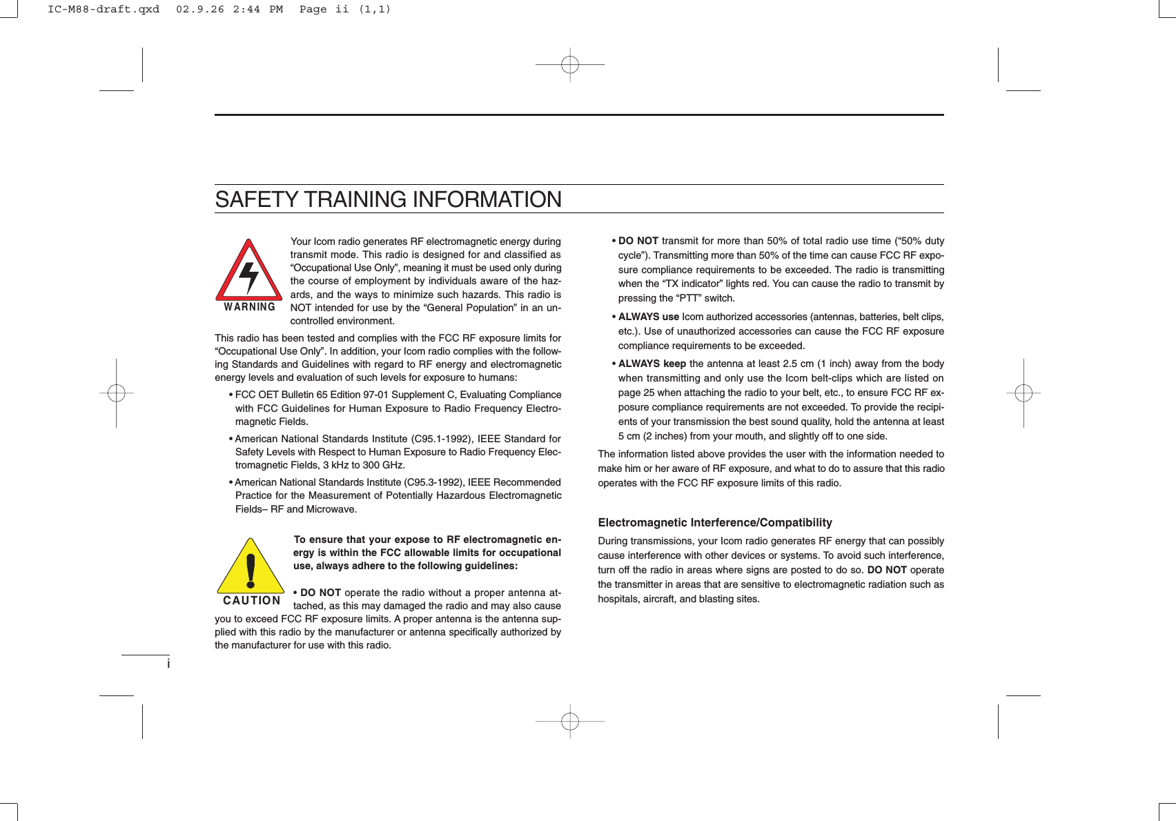
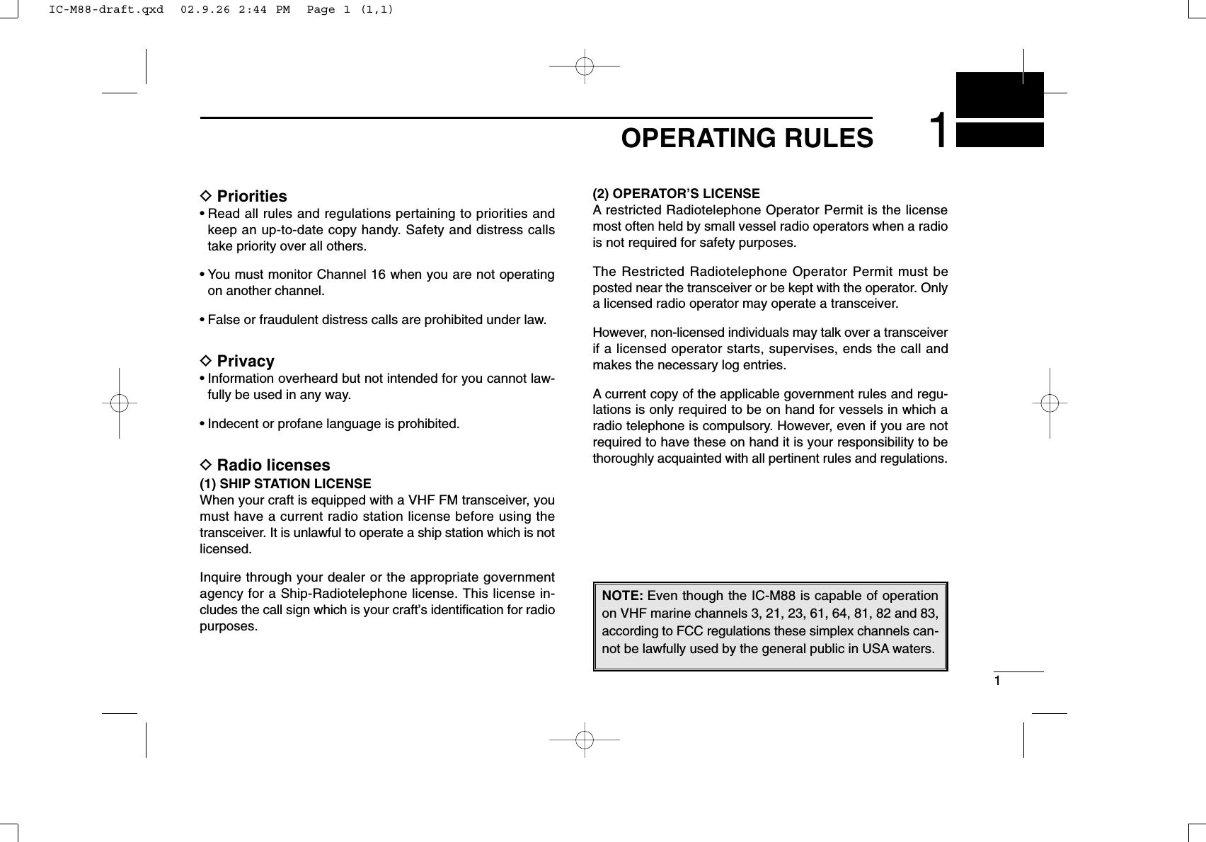
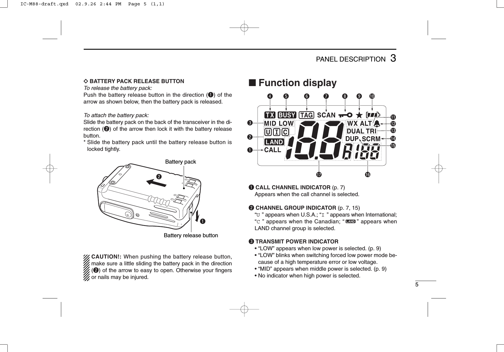
![43PANEL DESCRIPTIONqCHANNEL UP/DOWN SWITCHES [Y]/[Z]•Select an operating channel.•Selects the SET mode condition of the item.(p. 16)• Checks tag channels or changes scanning di-rection during scan. (p. 13)•Sets and clears the displayed channel as a tag(scanned) channel when pushed both switches.• While turning power ON, clears all tag chan-nels in the selected regular channel groupwhen pushed both switches.wCHANNEL/WEATHER CHANNEL SWITCH[CH/WX•U/I/C/L]•Selects and toggles the regular channels andweather channel when pushed. (pgs. 7, 8, 15)•Selects one of 4 regular channels in se-quence when pushed for 1 sec. (pgs. 7, 15)- U.S.A., International, Canadian and Landchannels are available.•Push to return to the condition before select-ing the channel when the priority channel orthe call channel is selected.eSQUELCH SWITCH [SQL•MONI] (p. 10)•Push this switch, then set the squelch levelwith [Y]/[Z].• Manually opens the squelch for channel mon-itoring when pushed for 1 sec.•While pushing this switch, turn the power ONto enter the set mode.r0 PTT SWITCH [PTT]Push and hold to transmit; release to receive.tVOLUME CONTROL [OFF/VOL]Turns power ON and adjusts the audio level.yANTENNA (p. 3)Connects the supplied antenna.uSCAN [SCN•DUAL] (pgs. 13, 14)•Starts and stops normal or priority scan.•Enters Watch mode when pushed for 1 sec.iTRANSMIT POWER/LOCK SWITCH[H/L•LOCK]•Selects high, middle or low power whenpushed. (p. 9)•Toggles the lock function ON/OFF whenpushed for 1 sec. (p. 11)oCHANNEL 16 SWITCH [16•9]•Selects Channel 16 when pushed. (p. 7)•Selects the call channel when pushed for1 sec. (p. 7)•Enters call Channel write mode when the callchannel is selected and this switch is pushedfor 3 sec. (p. 11)quiwertyo■Front, top and side panelsIC-M88-draft.qxd 02.9.26 2:44 PM Page 4 (1,1)](https://usermanual.wiki/ICOM-orporated/IC-M88/User-Guide-278446-Page-10.png)
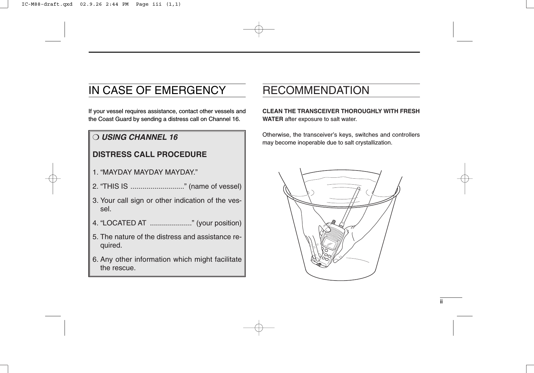
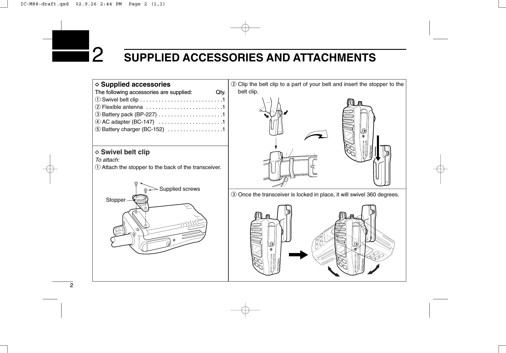
![74BASIC OPERATIONDChannel 9 (Call channels)Channel 9 is the leisure-use call channel. Each regular chan-nel group has separate call channels. In addition, each callchannel is monitored during tri-watch. The call channels canbe programmed (p. 11) and are used to store your most oftenused channels in each channel group for quick recall.qPush [16•9] for 1 sec. to select the call channel for the se-lected channel group.•“CALL” and call channel number appear. •Each channel group may have its own call channel after chang-ing a call channel.wPush [CH/WX•U/I/C/L] to return to the condition before se-lecting channel 9 (call channel), or push [Y]/[Z] to select op-erating channel.■Channel selectionDChannel 16Channel 16 is the distress channel. It is used for establishinginitial contact with another station and for emergency com-munications. Channel 16 is automatically monitored duringboth dualwatch and tri-watch. While standing by, you mustmonitor channel 16.qPush [16•9] to select channel 16.wPush [CH/WX•U/I/C/L] to return to the condition before se-lecting channel 16, or push [Y]/[Z] to select operatingchannel.PushPushfor 1 sec.IC-M88-draft.qxd 02.9.26 2:44 PM Page 7 (1,1)](https://usermanual.wiki/ICOM-orporated/IC-M88/User-Guide-278446-Page-13.png)
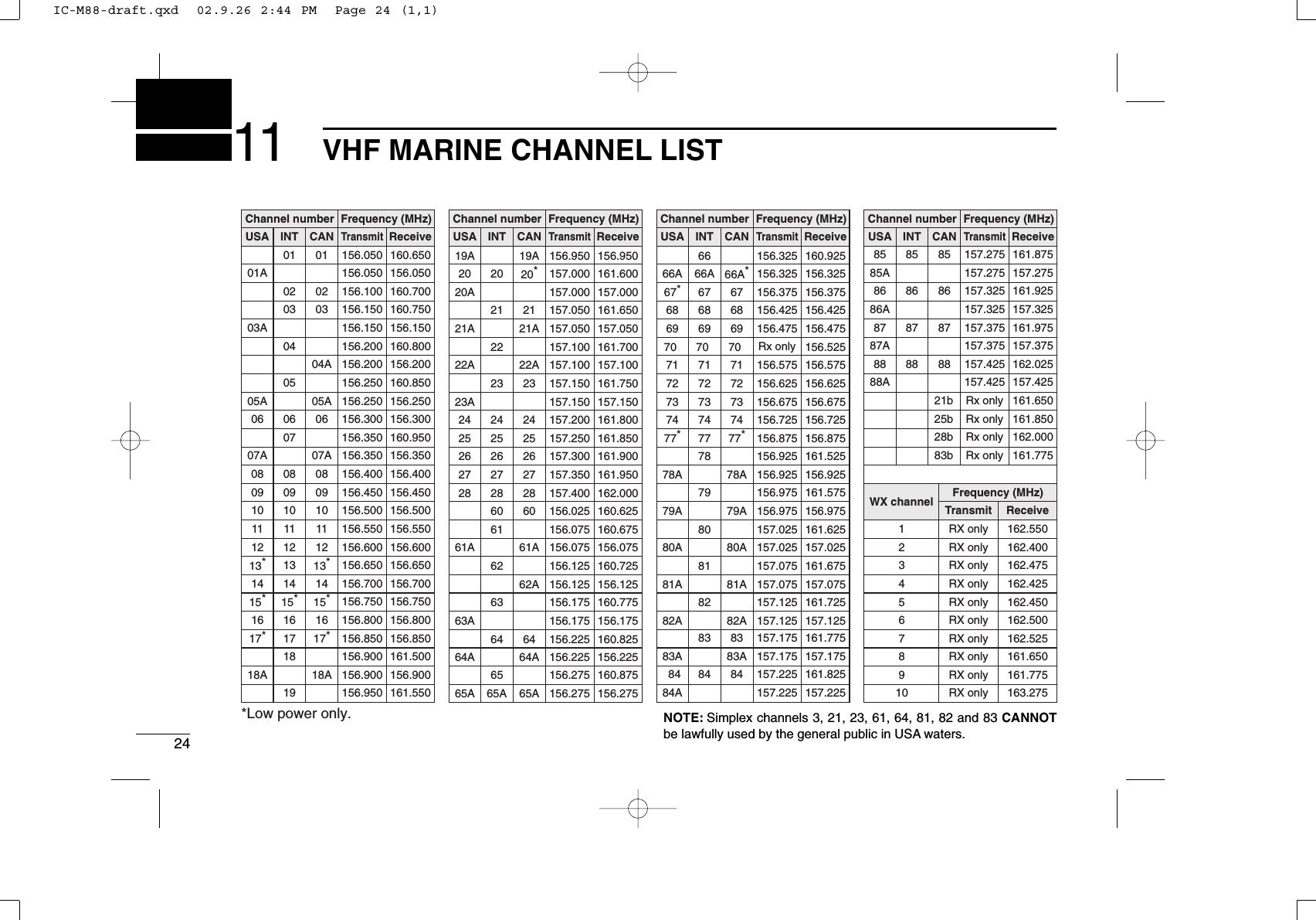
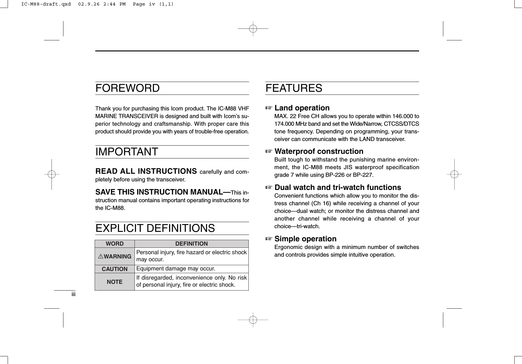
![84BASIC OPERATIONDWeather channelsThere are 10 weather channels. They are used for monitoringweather channels from the NOAA (National Oceanographicand Atmospheric Administration) broadcasts.The IC-M88 can detect a weather alert tone on the selectedweather channel while receiving in another channels or scan-ning. See the “SET mode items” on p. 16.qPush [CH/WX•U/I/C/L] to select the weather channel group.wPush [Y]/[Z] to select a weather channel.ePush [CH/WX•U/I/C/L] to return to the condition before se-lecting weather channel group.DU.S.A., International and Canadian channelsThere are 57 U.S.A., 57 International, and 61 Canadian chan-nels. These channel groups may be specified for the operat-ing area.qPush [CH/WX•U/I/C/L] to select a regular channel.•If a weather channel appears, push [CH/WX•U/I/C/L] again.wPush [Y]/[Z] to select a channel.•“DUP” appears for duplex channels.eTo change the channel group, push [CH/WX•U/I/C/L] for1 sec.•U.S.A., International and Canadian channels can be selected insequence.PushPush for 1 sec.U.S.A. channelsInternational channels Canadian channelsIC-M88-draft.qxd 02.9.26 2:44 PM Page 8 (1,1)](https://usermanual.wiki/ICOM-orporated/IC-M88/User-Guide-278446-Page-14.png)
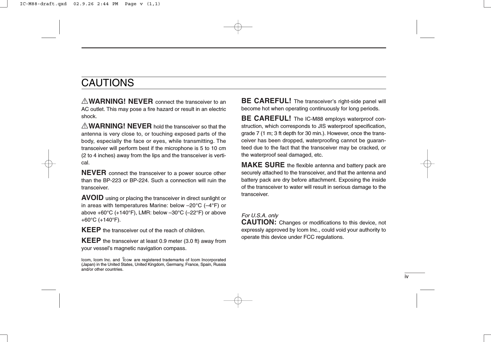
![94BASIC OPERATIONqRotate [OFF/VOL] clockwise to turn power ON.- Use the squelch function to mute any audio noise if necessary.See page 10 for details.wPush* [SQL•MONI] for 1 sec., and rotate volume to setaudio output level.*According to Monitor action selection in SET mode (p. 18).ePush [Y]/[Z] to select the desired channel.- When receiving a signal, “BUSY” appears and audio is emittedfrom the speaker.- Further adjustment of [OFF/VOL] may be necessary at this point.rPush [H/L•LOCK] to select the output power if necessary.- “LOW” appears when low power is selected; “MID” appearswhen middle power is selected; no indicator when high power isselected.- Choose low power to conserve battery power, choose highpower for longer distance communications.- Some channels are for low power only.tPush and hold [PTT] to transmit, then speak into themicrophone.- “TX” appears.- Channel 70 cannot be used for transmission (for GMDSS use).yRelease [PTT] to receive.■Receiving and transmittingCAUTION: Transmitting without an antenna maydamage the transceiver.IMPORTANT: To maximize the readability of your transmit-ted signal, pause a few sec. after pushing [PTT], hold themicrophone 5 to 10 cm (2 to 4 inches) from your mouth andspeak at a normal voice level.NOTE: The transceiver has a power save function to con-serve the battery power and cannot be turned OFF. Thepower save function activates automatically when no sig-nal is received for 5 sec.For U.S.A version: To prevent accidental prolonged trans-mission, etc., the IC-M88 has a time-out timer function. Thistimer cuts a transmission OFF after 5 min. of continuoustransmission.eSet channelw Set squelch levelq Power ONw Set volumerSet output powert Push and hold to transmity Release to receiveIC-M88-draft.qxd 02.9.26 2:44 PM Page 9 (1,1)](https://usermanual.wiki/ICOM-orporated/IC-M88/User-Guide-278446-Page-15.png)
![104BASIC OPERATION■Adjusting the squelch levelThe IC-M88 has a squelch even though there is no control knobfor it. In order to receive signals properly, as well as for scan tofunction, the squelch must be adjusted to a suitable level.qPush [SQL•MONI], then adjust the squelch level with [Y]/[Z].- “SL” indicator appears.- There are 11 squelch levels to choose from: OP is completelyopen; 10 is the maximum squelch level.- When no keys are pushed for 5 sec., the transceiver returns tonormal condition.wPush [SQL•MONI] again to return to normal condition.■Automatic backlightingThis function is convenient for nighttime operation. The auto-matic backlighting can be activated in SET mode. (p. 18)➥Push any key except for [PTT] to turn the backlighting ON.•The backlighting is automatically turned OFF after 5 sec.of inac-tivity.■Optional voice scrambleroperation (intrinsically safe version only)DActivating the scramblerThe optional voice scrambler provides private communica-tions. In order to receive or send scrambled transmissions,you must first activate the scrambler function.qSelect an operating channel ex-cept channel 16, 70 or weatherchannels.wPush [SCN•DUAL] while push-ing and holding [SQL•MONI].•“SCRM” appears.eTo turn the scrambler functionOFF, repeat step w.•“SCRM” disappears.DProgramming scramble codesThere are 32 codes (01 to 32) available for programming. Setthe code in SET mode. In order to understand on another, alltransceivers in your group must have the same scramble code,as well as the same scrambler unit. See page 19 for scramblercode setting details.RECOMMENDATION: Use the optional speaker-micro-phone during voice scrambling operation for much cleareraudio readability.Appears when the voice scrambler function is in use.IC-M88-draft.qxd 02.9.26 2:44 PM Page 10 (1,1)](https://usermanual.wiki/ICOM-orporated/IC-M88/User-Guide-278446-Page-16.png)
![111BASIC OPERATION■Call channel programmingThe call channel key is used to select channel 9 by default,however, you can program your most often-used channels ineach channel group for quick recall.qPush [CH/WX•U/I/C/L] for 1 sec.several times to select the de-sired channel group (USA, INT,CAN) to be programmed.wPush [16•9] for 1 sec. to selectthe call channel of the selectedchannel group.•“CALL” and call channel numberappear.ePush [16•9] again for 3 sec. (untillong beep changes to 2 shortbeeps) to enter call channel pro-gramming condition.•Call channel number and channelgroup to be programmed flashes.rPush [Y]/[Z] to select the de-sired channel.tPush [16•9] to program the dis-played channel as the call chan-nel.•The call channel number andchannel group stop flashing.■Lock functionThis function electronically locks all keys (except for [PTT],[SQL•MONI] and [H/L•LOCK]) to prevent accidental channelchanges and function access.• Push [H/L•LOCK] for 1 sec. to turn the lock function ON andOFF.Appears while the lock function is used.IC-M88-draft.qxd 02.9.26 2:44 PM Page 11 (1,1)](https://usermanual.wiki/ICOM-orporated/IC-M88/User-Guide-278446-Page-17.png)
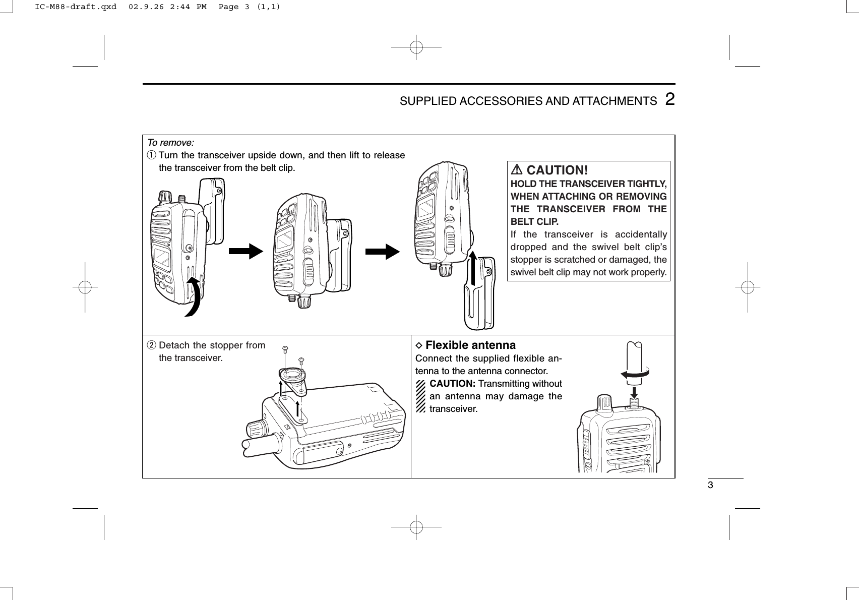
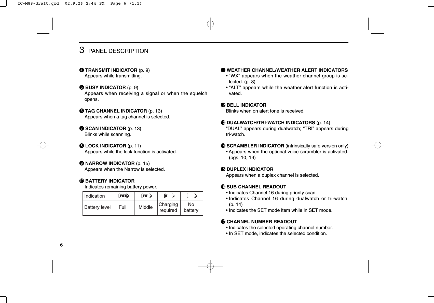
![135SCAN OPERATION■Setting tag channelsFor more efficient scanning, add desired channels as tagchannels or clear tag channels for unwanted channels. Chan-nels, set as non-tag channels will be skipped during scanning.Tag channels can be assigned to each channel group (USA,INT, CAN) independently.qSelect the desired channel group (USA, INT, CAN) by push-ing [CH/WX•U/I/C/L] for 1 sec., if desired.wSelect the desired channel to set as a tag channel.ePush both [Y] and [Z] to set the displayed channel as atag channel.•“TAG” appears in the function display.rTo cancel the tag channel setting, push both [Y] and [Z].•“TAG” disappears.• Clearing all tag channels in the selected channel groupWhile pushing and holding both [Y] and [Z], turn power ONto clear all tag channels in the channel group.■Starting a scanSet weather alert function, scan type, scan resume timer andauto scan function in advance, using SET mode. (pgs. 16, 17)qSelect the desired channel group (USA, CAN, INT) bypushing [CH/WX•U/I/C/L] for 1 sec., if desired.•When the weather alert function is in use, select the desiredweather channel with [CH/WX•U/I/C/L] and [Y]/[Z].wPush [SCN•DUAL] to start priority or normal scan.•“SCAN” blinks in the function display.•“16” appears during priority scan.•When a signal is received, scan pauses until the signal disap-pears or resumes after pausing 5 sec. according to SET modesetting. (Channel 16 is still monitored during priority scan.)•Push [Y]/[Z] to check the scanning tag channels, to change thescanning direction or resume the scan manually.eTo stop the scan, push [SCN•DUAL].•“SCAN” disappears.•Pushing [PTT], [16•9] or [CH/WX•U/I/C/L] also stops the scan.Push Scan starts.Scan pauses when receiving a signal and audio is emitted. Pushto stop the scan.[Example]: Starting a normal scan.IC-M88-draft.qxd 02.9.26 2:44 PM Page 13 (1,1)](https://usermanual.wiki/ICOM-orporated/IC-M88/User-Guide-278446-Page-19.png)
![146DUAL WATCH/TRI-WATCH■DescriptionDualwatch monitors channel 16 while you are receiving an-other channel; tri-watch monitors channel 16 and the callchannel while receiving another channel.■OperationqSelect the desired operating channel.wPush [SCN•DUAL] momentarily to start dualwatch; push[SCN•DUAL] for 1 sec. to start tri-watch.•“DUAL” flashes during dualwatch; “TRI” flashes during tri-watch.•Beep tone sounds when a signal is received on channel 16.•Tri-watch becomes dualwatch when receiving a signal on the callchannel.eTo cancel dualwatch/tri-watch, push [SCN•DUAL] again.[Example]: Operating tri-watch on INT channel 07.DUALWATCH/TRI-WATCH SIMULATION•If a signal is received on channel 16, dualwatch/tri-watch pauseson channel 16 until the signal disappears.•If a signal is received on the call channel during tri-watch, tri-watch becomes dualwatch until the signal disappears.•To transmit on the selected channel during dualwatch/tri-watch,push and hold [PTT].•If no signal is received, the transceiver enters the power savingcondition for 0.5 sec. after checking the operating channel everycycle.Dualwatch Tri-watchCall channelTri-watch starts.Push for 1 sec.Signal is received on call channel.Signal received on channel 16 takes priority.Tri-watch resumes after the signal disappears.IC-M88-draft.qxd 02.9.26 2:44 PM Page 14 (1,1)](https://usermanual.wiki/ICOM-orporated/IC-M88/User-Guide-278446-Page-20.png)
![157LAND CHANNEL OPERATION■LAND ChannelThere are 57 LAND channels. This channel group may bespecified for the operating area. Moreover, you can programmax. 22 Free channels, allocated LMR frequency, and yourtransceiver can communicate with the LAND transceiver.Please contact your dealer for details.qPush [CH/WX•U/I/C/L] to select a regular channel.•If a weather channel appears, push [CH/WX•U/I/C/L] again.wTo change the channel group, push [CH/WX•U/I/C/L] for1 sec several times.•LAND channel can be selected.ePush [Y]/[Z] to select a channel.•“DUP” appears for duplex channels.NOTE: The basic setting ways (e.g. Call channel program-ming) are same as the U.S.A., International and Canadianchannels. Refer to the appropriate page for details.■Function displayFree channel is used for frequency setting. When Narrow,DTCS or CTCSS frequency is set, function indicator appearson the LCD.PushAppears when DTCSfrequency is set.Appears when CTCSSfrequency is set.Appears when Narrowis set.IC-M88-draft.qxd 02.9.26 2:44 PM Page 15 (1,1)](https://usermanual.wiki/ICOM-orporated/IC-M88/User-Guide-278446-Page-21.png)
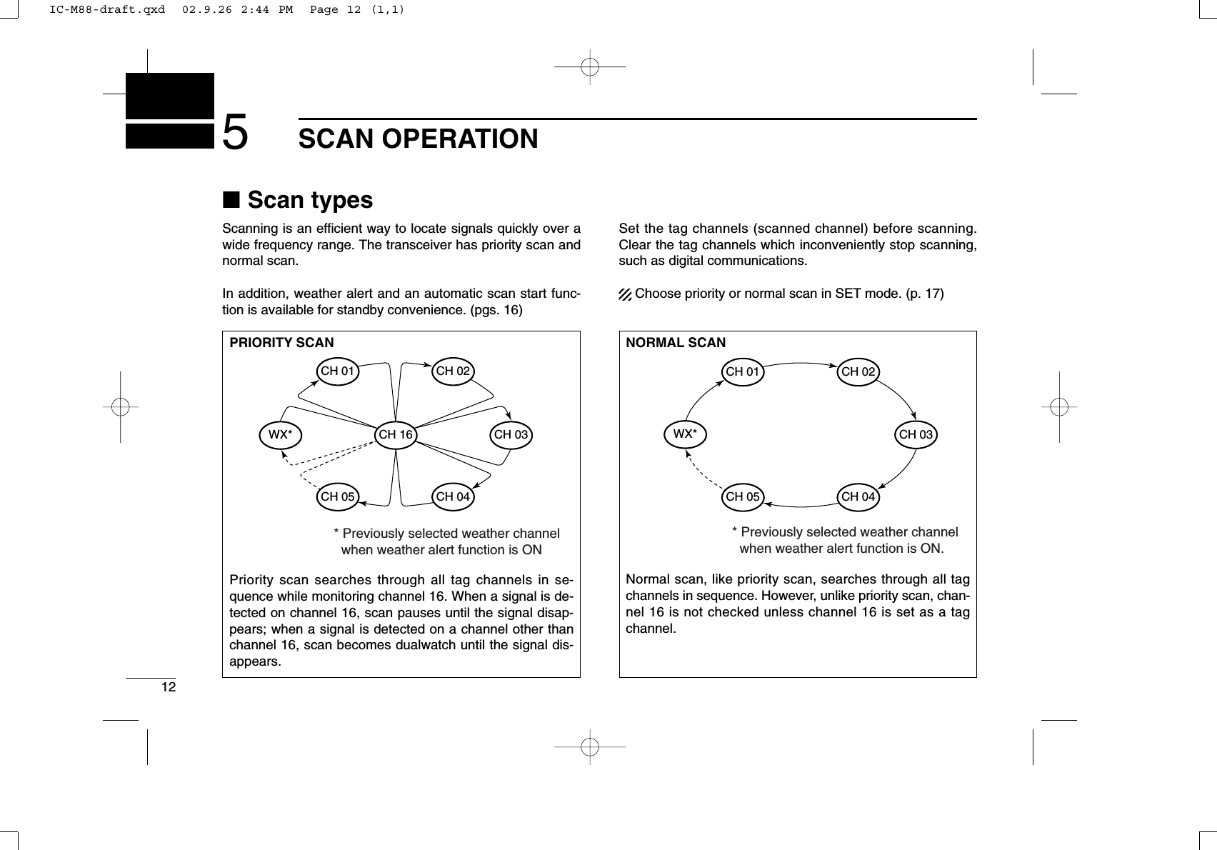
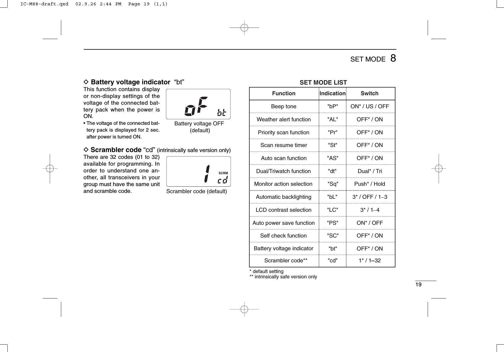
![168SET MODE■SET mode programmingSET mode is used to change the condition of 13 transceiverfunctions: beep tone function, weather alert function, scantype (normal/priority), scan resume timer, auto scan function,dual/tri-watch, monitor function, automatic backlighting, con-trast, power save function, self check function, battery volt-age and scrambling code.When no optional voice scrambler unit is installed, scramblingcode cannot be set. (will not be displayed)qTurn power OFF.wWhile pushing [SQL•MONI], turn power ON and continuepushing [SQL•MONI] until “bP” appears.eRelease [SQL•MONI].rPush [Y]/[Z]to select the desired condition of the item.tPush [SQL•MONI] to select the desired item, if necessary.yTo exit SET mode, turn the power OFF, then ON again, orpush [16•9].■SET mode itemsDBeep tone “bP”You can select silent operationby turning the beep tones OFF,or you can have confirmationbeeps sound at the push of aswitch, by turning the beeptones ON.DWeather alert function “AL”An NOAA broadcast stationtransmits a weather alert tonebefore any important weather an-nouncements. When the weatheralert function is turned ON, thetransceiver detects the alert, thebell indicator blinks and sounds abeep tone until the transceiver isoperated. The previously se-lected (used) weather channel ischecked any time during standby,or while scanning, when thepower save function is activated.•“ALT” appears when the function isset ON.Beep tone ON (default)Weather alert function ONWeather alert function OFF (default)WeatheralertScan resumetimerAutoscanSelfcheckBatteryvoltageScantypeBeep toneStarting itemPush [SQL/MONI]MonitorswitchAutomaticbacklightingLCDcontrastAutopower saveDual/Tri-watchScramblercodeIC-M88-draft.qxd 02.9.26 2:44 PM Page 16 (1,1)](https://usermanual.wiki/ICOM-orporated/IC-M88/User-Guide-278446-Page-22.png)
![178SET MODEDPriority scan function “Pr”The transceiver has 2 scantypes. Normal scan and priorityscan. Normal scan searches alltag channels in the selectedchannel group. Priority scansearches all tag channels in se-quence while monitoring Chan-nel 16.DScan resume timer “St”The scan resume timer can beselected as a pause (OFF) ortimer scan (ON). When OFF isselected, the scan pauses untila received signal disappears.When ON is selected, the scanpauses for 5 sec. after receivinga signal and then resumes evenif the signal is still being re-ceived.DAuto scan function “AS”While in standby, this functionautomatically starts the desiredscan (normal or priority scan)30 sec. after operation.• Scan indicator blinks whilescanning.DDual/Tri-watch function “dt”This item can be selected asdualwatch or tri-watch. See p.14 for details.DMonitor action selection “Sq”The monitor function cuts off thesquelch function temporarily.This selection contains PUSHor HOLD settings as shownbelow.• PUSH (Pu):After pushing the [SQL•MONI]for 1 sec., the squelch functionis cut off until [SQL•MONI] isreleased. (default)• HOLD (Ho):After pushing the [SQL•MONI]for 1 sec., the squelch functionis cut off continuously until another key is pushed.Normal scan (default)Scan timer OFF (default)Dualwatch function (default)Auto scan OFF (default)Monitor switch PUSH (default)IC-M88-draft.qxd 02.9.26 2:44 PM Page 17 (1,1)](https://usermanual.wiki/ICOM-orporated/IC-M88/User-Guide-278446-Page-23.png)
![23TROUBLESHOOTINGPROBLEM POSSIBLE CAUSE SOLUTION.REF.No sound comes fromthe speaker.•Squelch level is too deep.•Volume level is too low.•Speaker has been exposed to water.p. 10p. 9—•Set squelch to the threshold point.•Set [OFF/VOL] to a suitable level.•Drain water from the speaker.No power comes ON. •The battery is exhausted.•Bad connection to the battery pack.p. 20p. 5•Recharge the battery pack.•Check the connection to the transceiver.Transmitting is impossi-ble, or high power cannot be selected.•Some channels are for low power or re-ceive only.•The battery is exhausted.•The output power is set to low.pgs. 4, 5p. 20p. 4•Change channels.•Recharge the battery pack.•Push [H/L•LOCK] to select high power.The display channelcannot be changed.•Lock function is activated. •Push [H/L•LOCK] for 1 sec. to cancel thefunction.p. 11Scan does not start. •“TAG” channels are not programmed. •Set the desired channels as “TAG” channels. p. 13No beeps sound. •Beep tones are turned OFF. •Set the beep tones to ON (Fix Beep/UserBeep) in SET mode.p. 16Self check error.(Temperature error)•Transceiver’s inside temperature is belowMarine; –20°C (–4°F) or above +60°C (+140°F)LMR; –30°C (–22°F) or above +60°C (+140°F).•Leave the transceiver at room temperaturefor a while. Turn the power ON to check if theinternal temperature has returned to normal.Self check error.(Battery voltage error)•The connected battery pack’s voltage ismore than 11 V.•Verify the battery voltage is correct.——Self check error.(Water intrusion error)•Water has entered the transceiver. •Have the transceiver checked at your localdistributor or dealer to see whether the trans-ceiver works properly or not.—10IC-M88-draft.qxd 02.9.26 2:44 PM Page 23 (1,1)](https://usermanual.wiki/ICOM-orporated/IC-M88/User-Guide-278446-Page-29.png)