ICOM orporated IC-R3 Scanning Receiver User Manual IC R3 2
ICOM Incorporated Scanning Receiver IC R3 2
UserManual.wiki
>
ICOM orporated
>
IC R3 User Manual
Manual
Navigation menu
Upload a User Manual
Namespaces
Wiki Guide
HTML
PDF
Info
Views
User Manual
Discussion / Help
Navigation
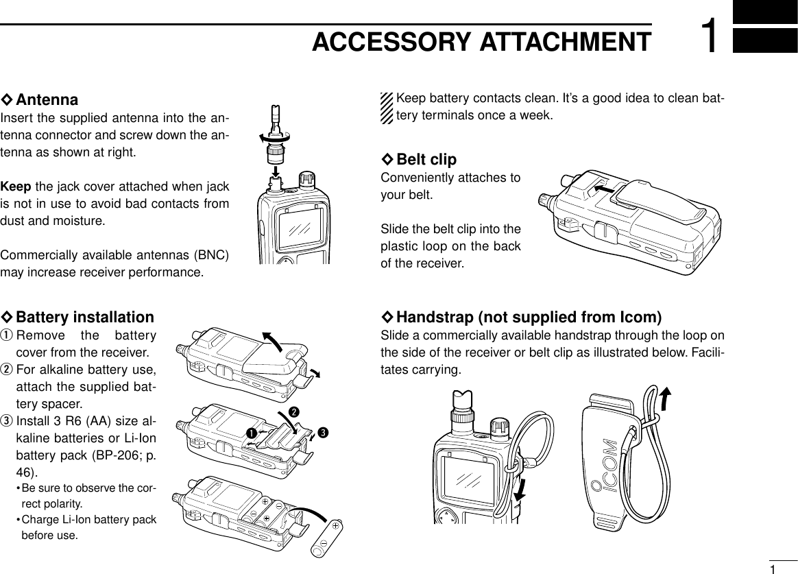
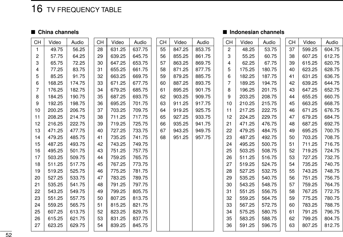
![iFOREWORDREAD ALL INSTRUCTIONS carefully and completelybefore using the receiver.SAVE THIS INSTRUCTION MANUAL —This in-struction manual contains important operating instructions forthe IC-R3.EXPLICIT DEFINITIONSThe explicit definitions below apply to this instruction manual.CAUTIONSRWARNING! NEVER operate the receiver with a head-set or other audio accessories at high volume levels. Hearingexperts advise against continuous high volume operation. Ifyou experience a ringing in your ears, reduce the volume levelor discontinue use.AVOID using or placing the receiver in direct sunlight or inareas with temperatures below –10°C (+14°F) or above+60°C (+140°F).Even when the receiver power is OFF, a slight current stillflows in the circuits. Remove batteries from the receiver whennot using it for a long time, otherwise, the installed batterieswill become exhausted.REMOVE any cables from the [DC 6V] jack after operation orcharging a battery pack.LCDs are produced using high-density manufacturing tech-nology resulting in 99.98% active dots, however, up to 0.02%of the dots may be non-active and/or continuously active. Thisis normal and does not indicate LCD malfunction.For U.S.A. onlyCAUTION: Changes or modifications to this device, not ex-pressly approved by Icom Inc., could void your authority tooperate this device under FCC regulations.WORDR WARNINGCAUTIONNOTEDEFINITIONPersonal injury, fire hazard or electric shock may occur.If disregarded, inconvenience only. No risk of personal injury, fire or electric shock.Equipment damage may occur.Versions of the IC-R3 which display the “CE”symbol on the serialnumber seal, comply with the essential requirements of the Euro-pean Radio and Telecommunication Terminal Directive 1999/5/EC.](https://usermanual.wiki/ICOM-orporated/IC-R3/User-Guide-118953-Page-2.png)
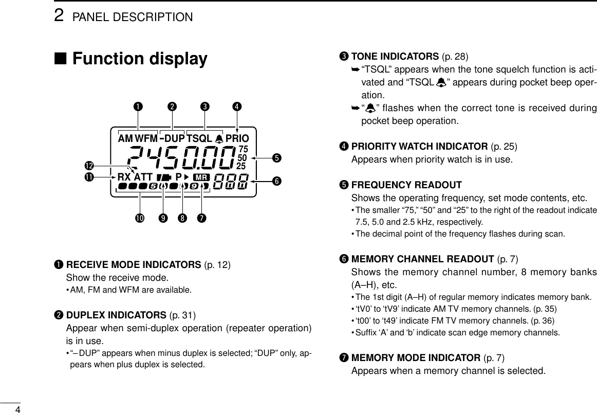
![■Panel descriptionqANTENNA CONNECTOR (p. 1)Connects the supplied antenna.wFUNCTION SWITCH [FUNC]While pushing this switch, other switches and tuning dialperform secondary functions.•“Push [FUNC] + a switch”means “while pushing the [FUNC]switch, push the switch”as indicated by the mark e.g. [↕] etc.eMULTI FUNCTION SWITCH [MULTI]➥Push [↕] to adjust the audio level. (p. 11)➥Push [FUNC] + [↕] to toggle between AM TV (frequencyselection), amateur TV (ATV-type) and WFM/FM/AMmodes when the color LCD is OFF. (p. 34)➥Push [FUNC] + [↕] for 2 sec. to toggle the color LCD ONand OFF (p. 6, 30 MHz and above only).➥Push [FUNC] + [↕] to select color LCD function when thecolor LCD is ON. (p. 6)➥Push [↔] to select the operating band (VHF, UHF, etc.)in VFO mode. (p. 7)•Broadcast, HF, 50 MHz, FM broadcast, VHF avionics, 144MHz, 300 MHz, 400 MHz, 800 MHz, 1200 MHz, 2400 MHzand TV bands (channel selection) can be selected.➥Push [FUNC] + [↔] to select the dial select step. (p. 39)➥Push [↔] for 2 sec. to start a scan. (pgs. 19, 20)➥Push [FUNC] + [↔] for 2 sec. to start a tone scan. (p.30)Push [↕] means push óup or down; and push [↔] meanspush óleft or right.rPOWER SWITCH [POWER]Push for 2 sec. to toggle the receiver power ON and OFF.22PANEL DESCRIPTIONqwertyuioColor LCD (p. 6)Sub LCD (p. 4)SPEAKER!0!1](https://usermanual.wiki/ICOM-orporated/IC-R3/User-Guide-118953-Page-6.png)
![32PANEL DESCRIPTIONtVFO/MEMORY SWITCH [V/M (SKIP)]➥Push [V/M] to toggle between VFO and memory modes.(p. 7)➥Push [V/M] for 1 sec. to enter memory write mode.➥Push [V/M] for 2 sec. to write the operating frequencyinto the selected memory channel in VFO mode. Keeppushing for 2 sec. or more to automatically select thenext memory channel, if desired. (p. 14)➥Push [FUNC] + [(V/M)SKIP] to toggle the frequency skipfunction ON or OFF in VFO mode. (p. 24)➥Push [FUNC] + [(V/M)SKIP] to toggle the channel asskip, program skip or non-skip channel in memorymode. (p. 22)➥Push [FUNC] + [(V/M)SKIP] for 2 sec. to program thememory name while displaying the memory channel inthe color LCD. (p. 17)yMODE SWITCH [MODE (SET)]➥Push [MODE] to select the receive mode. (p. 12)➥Push and hold [MODE] to enter tuning step setting con-dition and rotate the tuning dial to select the tuning step.(p. 8)➥Push [FUNC] + [(MODE)SET] to enter set mode. (p. 38)➥Push [FUNC] + [(MODE)SET] for 2 sec. to toggle thelock function ON and OFF. (pgs. 9, 24)uMONITOR SWITCH [SQL (ATT)]➥Push and hold to temporarily open the squelch andmonitor the operating frequency. (pgs. 12, 41)➥While pushing [SQL], rotate the tuning dial to set thesquelch threshold level. (p. 11)➥Push [FUNC] + [(SQL)ATT] to enter the attenuator set-ting condition and rotate the tuning dial to set the atten-uation level. (p. 9)iEXTERNAL DC POWER JACK [DC 6V]Allows charging of the BP-206 using the BC-136A/D wallcharger, or using an optional CP-18A/E cigarette lighter cable.oAUDIO AND VIDEO OUTPUT JACK [A/V OUT]Outputs a composite video and audio signals. (p. 5)!0 TUNING DIAL [DIAL]➥Rotate [DIAL] to set operating frequencies, memorychannels, set mode contents, etc. (pgs. 7, 38)➥While scanning, changes the scanning direction. (p. 19)➥While pushing [SQL], sets the squelch level. (p. 11)➥While pushing [FUNC], sets the operating frequency in 100kHz, 1 MHz or 10 MHz steps in VFO mode. (pgs. 8, 39)➥While pushing [FUNC], sets the memory bank in mem-ory mode. (p. 16)➥While pushing [↔], selects programmed scan bank ormemory bank in VFO or memory mode, respectively.Release [↔] to start the scan. (pgs. 19, 20)!1 EXTERNAL SPEAKER JACK [SP]Connects an optional earphone or headphone. The inter-nal speaker will not function when any external equipmentis connected. (See p. 55 for a list of available options.)](https://usermanual.wiki/ICOM-orporated/IC-R3/User-Guide-118953-Page-7.png)
![52PANEL DESCRIPTIONiSKIP SCAN INDICATOR (pgs. 22, 24)➥“"”appears when the selected memory channel is setas a skip channel in memory mode.➥“P"”shows that the skip frequency function is turnedON or OFF in VFO mode.➥“P"”appears when the selected memory channel is setto be skipped during VFO scan (full, band and pro-grammed scan) in memory mode.oBATTERY INDICATORS➥Both segments appear when the batteries have enoughcapacity.➥Only the right segment appears when the batteries arenearing exhaustion.•“Low V”appears when battery replacement is necessary andthe color LCD is ON.•The U.S.A. version automatically turns itself OFF when the re-ceiver detects that battery replacement is necessary.!0 S (SIGNAL) INDICATORSShow the relative signal strength while receiving.!1 BUSY INDICATOR“RX”appears when receiving a signal or when the squelchis open.!2 ATTENUATOR INDICATOR (p. 9)Appears when the attenuator function is in use.•Audio and video output jack information•Video output impedance : 75 Ω, 1 Vp-p typical•Audio output impedance : 1 kΩ, 300 mVrms typicalAudioAudio[A/V OUT]3-conductor 3.5 (d) mm (1⁄8˝)connectorVideoVideoTelevisionGroundGroundTo [A/V OUT]](https://usermanual.wiki/ICOM-orporated/IC-R3/User-Guide-118953-Page-9.png)
![62PANEL DESCRIPTION■Dual LCDThe receiver has dual LCDs for versatile display selection.The color LCD has 5 screens and 1 optional screen as fol-lows:simple, multi-function, band scope, direction finding, TV (fre-quency selection) and amateur TV* screen.*Amateur TV screen can be selected for the ATV-type and1200/2400 MHz bands only.The color LCD can be used when the operating frequencyis 30 MHz and above.qPush [FUNC] + [↕] for 2 sec. to turn the color LCD ON, ifdesired.wPush [FUNC] + [↕] momentarily one or more times to tog-gle the screen of the color LCD.While the color LCD is in use, the sub LCD displays thevoltage of the power source.RXAppears when simple screen is selected.VOLRXFM PSKIP146.100.000TS 15.0 S1 3 5 7 9FM PSKIP146.100.00015.0 TSFM PSKIP146.100.00015.0 TSFM PSKIP146.100.000 TS= 15.0 SWEEP- 10KS1 3 5 7 9 RX VOLFUNC+momentarilyDirection findingscreen (p. 37)Simple screen ATV screen (p. 36; ATV type, 1200/2400 MHz bands only)TV screen (p. 34;frequency selection)Multi-functionscreenBand scopescreen (p. 33)](https://usermanual.wiki/ICOM-orporated/IC-R3/User-Guide-118953-Page-10.png)
![73FREQUENCY AND CHANNEL SETTING■VFO and memory channelsThis receiver has 2 normal operating modes: VFO mode andmemory mode.VFO mode is used for setting a de-sired frequency within the fre-quency coverage.➥Push [V/M] to select VFO mode.Memory mode is used for opera-tion of memory channels whichhave programmed frequencies.➥Push [V/M] to select memorymode.•“X”or “M:”appears when a mem-ory channel is selected.•To program a memory, refer to p. 14.•TV band and ATV (ATV type) haveseparate memory channels (pgs.35, 36)What is VFO?VFO is an abbreviation of Variable Frequency Oscillator. Fre-quencies for receiving are generated and controlled by theVFO.■Operating band selectionThe receiver can receive thebroadcast band, HF band, 50MHz band, FM broadcastband, VHF avionics band, 144MHz band, 300 MHz band,400 MHz band, 800 MHzband,* 1200 MHz, 2400 MHzor TV band.*Some frequencies cannot be re-ceived with the U.S.A. version.➥Push [↔] several times toselect the desired band.•When a memory channel isselected, the first push of [↔]selects VFO mode.Amateur TV screen is alsoselected for the ATV-typeIC-R3. (p. 36)FMPFMPFM PSKIP145.000.00015.0 TSM:A00“ ” or “M:” appears.0.495–1.620 MHz1.625–29.995 MHz30.0–75.995 MHz76.0–107.995 MHz136.0–255.095 MHz108.0–135.995 MHz255.1–382.095 MHz382.1–769.795 MHz769.8–960.095 MHz960.1–1399.995 MHz1400.0–2450.095 MHzTV band (CH selection)](https://usermanual.wiki/ICOM-orporated/IC-R3/User-Guide-118953-Page-11.png)
![83FREQUENCY AND CHANNEL SETTING■Setting a frequencyqSelect the desired band with [↔].wRotate [DIAL] to change the frequency.•The frequency changes according to the preset tuning steps. Seethe right section for selecting the tuning step.•Some TV channels may be set as skip channels by default andcan be selected by rotating [DIAL] while pushing [FUNC]. (p. 34).•Push [↔] while pushing [FUNC] to change the frequency in 100kHz, 1 MHz or 10 MHz steps.The 1 MHz tuning step (dial select step) can be set to 100kHz, 1 MHz or 10 MHz tuning steps in set mode. See p. 39for details.■Setting a tuning stepTuning steps can be selected for each band, however, the tun-ing step of the broadcast band is fixed to 9 kHz steps exceptfor U.S.A. and Canada versions. The following are available.•5 kHz •6.25 kHz* •10 kHz •12.5 kHz •15 kHz•20 kHz •25 kHz •30 kHz •50 kHz •100 kHz*Not available for 1200 MHz band.qSelect the desired band, except for TV band, with [↔].wRotate [DIAL] while pushing [MODE] to select the desiredtuning step.FM146.100.00015.0 TS•15 kHz tuning step (Simple screen)•15 kHz tuning step (Sub LCD)FM755025FM755025[DIAL] changes the frequency according to the selected tuning step.While pushing [FUNC], [DIAL] changesthe frequency in 1 MHz steps (default).](https://usermanual.wiki/ICOM-orporated/IC-R3/User-Guide-118953-Page-12.png)
![93FREQUENCY AND CHANNEL SETTING■Selecting a memory channelqPush [V/M] to select memorymode.•“X”or “M:”appears when a mem-ory channel is selected.wRotate [DIAL] to change the indi-cated memory channel.•Only programmed memory chan-nels can be selected.•Rotate [DIAL] while pushing [FUNC]to change the memory bank.■Lock functionThe lock function prevents accidental frequency changes andaccidental function access.➥Push [FUNC] + [MODE] for 2 sec. to toggle the lock func-tion ON and OFF.•[POWER], [↕(VOL)] and [SQL] canstill be accessed while the lock func-tion is ON (default).•Accessible switches can be set to 1of 4 groups in set mode. See p. 42for details.■Attenuator functionThe attenuator prevents a desired signal from distorting whenvery strong signals are near the desired frequency or whenvery strong electric fields, such as from a broadcasting sta-tion, are near your location.The receiver has 4 attenuation levels for various operatingconditions. The attenuator functions when the operating fre-quency is 1149.995 MHz or below.qPush [FUNC] + [(SQL)ATT] to enter the attenuator settingcondition.wRotate [DIAL] to set the attenuation level 1–4 or turn theattenuator function OFF.•“ATT1”– “ATT4”appears in the color LCD when the color LCD isON; “ATT”appears in the sub display when the color LCD is OFF.ePush [(SQL)ATT] to exit the attenuator setting condition.FMATTS1 3 5 7 9VOLFM ATT4145.000.000TS 15.0 Shows when the attenuator is in use.Shows when the attenuator(level 4) is in use.FMPFMP[DIAL] changes thememory channel.While pushing [FUNC],[DIAL] changes the memory bank.FM“ L ” appears when thelock function is in use.](https://usermanual.wiki/ICOM-orporated/IC-R3/User-Guide-118953-Page-13.png)
![104BASIC OPERATION■ReceivingMake sure a charged battery pack or alkaline batteries are in-stalled. (pgs. 1, 46)qPush [POWER] for 2 sec. to turn power ON.wPush [↕] to set the desired audio level.•One of the LCDs shows the volume level while setting. See thenext page for details.ePush [↔] to select an operating band. (p. 7)rRotate [DIAL] to set an operating frequency. (p. 8)tSet the squelch level.•While pushing [SQL], rotate [DIAL].•The first click of [DIAL] indicates the current squelch level.•“LEVEL1”is loose squelch and “LEVEL9”is tight squelch.•“AUTO”indicates automatic level adjustment with a noise pulsecount system.•Push and hold [SQL] to open the squelch manually. (default be-haviour; p. 41)yWhen a signal is received:➥Squelch opens and audio is emitted from the speaker.➥The S indicators show the relative signal strength.➥The busy indicator appears when receiving a signal or when thesquelch is open.q Power switchw Set volumee Select band t Push for setting the squelch(Push to monitor)r Set frequencyt Set the squelch level For non-U.S.A. versionsIf the display mode selection is set as ‘manual’(p. 43) withthe color LCD ON, the receiver may not be able to turn it-self OFF when the battery becomes exhausted.Replace the battery and turn power OFF in this case.For U.S.A. versionThe U.S.A. version automatically turns itself OFF when thereceiver detects that battery replacement is necessary. Re-place the battery or charge the battery pack in this case.](https://usermanual.wiki/ICOM-orporated/IC-R3/User-Guide-118953-Page-14.png)
![114BASIC OPERATION■Setting volume levelThe audio level can be adjusted through 32 levels.➥Push [↕] to set the desired audio level.•Beep tone sounds while setting. This indicates the approximatesound level. (default behaviour; p. 40)•Pushing and holding these keys changes the audio level contin-uously.•One of the LCDs shows the volume level while setting.■Setting squelch levelThe squelch circuit mutes the received audio signal depend-ing on the signal strength. The receiver has 9 squelch levels,a continuously open setting and an automatic squelch setting.➥While pushing [SQL], rotate the[DIAL] to select the squelch level.•The first click of [DIAL] indicates thecurrent squelch level.•“LEVEL1”is loose squelch and“LEVEL9”is tight squelch.•“AUTO”indicates automatic leveladjustment with a noise pulse countsystem.•“OPEN”indicates continuously opensetting.S1 3 5 7 9VOLFM146.100.000TS 15.0 AUDIO LEVELINDICATION(Sub LCD)Min. setting (no audio):Initial setting:::Max. settingVolume levelS1 3 5 7 9VOLFM146.100.000TS 15.0 Automatic squelchMaximum levellevel 5](https://usermanual.wiki/ICOM-orporated/IC-R3/User-Guide-118953-Page-15.png)
![124BASIC OPERATION■Monitor functionThis function is used to listen to weak signals or to open thetone squelch manually.➥Push and hold [SQL] to monitor the operating frequency.•“RX”flashes while monitoring.The [SQL] switch can be set to ‘sticky’operation in setmode. (p. 41)You can monitor duplex communication by pushing the[SQL] switch when the duplex function is in use. (p. 31)■Receive mode selectionReceive modes are determined by the physical properties ofthe radio signals.The receiver has 3 receive modes: FM, AMand WFM modes. TV and ATV (ATV type only) also use WFMmode. The mode selection is stored independently in eachband and memory channels.Typically, AM mode is used for the AM broadcast stations(0.495–1.620 MHz) and air band (118–135.995 MHz), andWFM is used for FM broadcast stations (76–107.9 MHz).➥Push [MODE] one or more times to select the desired re-ceive mode.S1 3 5 7 9VOLFM146.010.000TS 15.0 S1 3 5 7 9VOLAM118.000.000TS 25.0 S1 3 5 7 9VOLWFM76.000.000TS 50.0 FM AM FMWAM mode WFM modeFM modeS1 3 5 7 9VOLRXFM146.100.000TS 15.0 FMRX](https://usermanual.wiki/ICOM-orporated/IC-R3/User-Guide-118953-Page-16.png)
![134BASIC OPERATIONTV screens cannot be selected by pushing [MODE]. See p.34 for TV operation details.■Display backlightingThe receiver has display backlighting with a 5 sec. timer fornighttime operation. The display backlighting can be turnedON continuously or turned OFF, if desired.➥Push any switch except [FUNC]; or, rotate [DIAL] to turn thebacklighting ON.•When auto backlighting is set, the backlighting will automaticallyturn OFF when switches and [DIAL] have not been operated for 5sec.◊Setting the backlighting conditionqPush [FUNC] + [(MODE)SET] momentarily to enter setmode.•Select a non-band scope screen in advance for color LCD.wRotate [DIAL] until “LIGHT”appears.•“LIGHt”disappears after 1 sec. and the previously selected back-lighting timer and “LI”appears when color LCD is OFF.ePush [↔] or rotate the tuning dial while pushing [FUNC] toselect the desired backlighting condition.rPush [(MODE)SET] to exit set mode.Pause Scan : 10SECPriority : OFFBeep Audio : VOLUMELight : AUTOA.Power OFF : OFFPause Scan : 10SECPriority : OFFBeep Audio : VOLUMELight : AUTOA.Power OFF : OFFPause Scan : 10SECPriority : OFFBeep Audio : VOLUMELight : OFFA.Power OFF : OFFAutomatic backlightingBacklighting set mode Continuously OFFFMWFMWRX RXFM TV mode(ATV type only)TV screenfrequency selection](https://usermanual.wiki/ICOM-orporated/IC-R3/User-Guide-118953-Page-17.png)
![■GeneralThe receiver has 400 memory channels in 8 banks (A–H) forstorage of often-used frequencies.◊Memory channel contentsThe following information can be programmed into memorychannels:•Operating frequency (p. 8)•Receive mode (p. 12)•Tuning step (p. 8)•Memory name (p. 17)•Duplex direction (DUP or –DUP) with an offset frequency(p. 31)•Tone squelch ON/OFF (p. 28)•Tone squelch frequency (p. 28)•Scan skip setting (p. 22)■Programming during selectionqPush [↔] to select an operating band.wSet the desired frequency:➥Set the frequency using [DIAL].➥Set other data (e.g. offset frequency, duplex direction,tone squelch frequency, etc.), if required.ePush [V/M] for 1 sec. to indicate memory channels.•Do not hold [V/M] for more than 2 sec., otherwise the previouslyselected memory channel will be overwritten.rRotate [DIAL] to select the desired channel.•VFO (VF), as well as regular memory channels, can be pro-grammed in this way.•Rotate [DIAL] while pushing [FUNC] to select a memory bank(A–H), programmed scan edge channel or VFO (VF).tPush [V/M] for 1 sec. to program.•Keep pushing for 2 sec. or more to automatically select the nextmemory channel, if desired.145MEMORY CHANNELSFM DUPTSQLPFMV/M SKIP V/M SKIPFUNCFM DUPTSQLPS1 3 5 7 9VOLFM PSKIPTSQL–DUP145.600.000TS 15.0 S1 3 5 7 9VOLFM146.010.000M:A00TS 15.0 S1 3 5 7 9VOL. . M:E40TS . S1 3 5 7 9VOLFM PSKIPTSQL–DUP145.600.000E41TS 15.0 for 1 sec.blankchannelfor 2 sec.for bankselection for CHselection+[EXAMPLE]: Programming ch 40 of memory bank E during selection (and ch 41 selection).](https://usermanual.wiki/ICOM-orporated/IC-R3/User-Guide-118953-Page-18.png)
![■Programming after selectionqSelect memory mode with [V/M].wSet the memory channel to be programmed with [DIAL].•Rotate [DIAL] while pushing [FUNC] to select a memory bank(A–H) or programmed scan edge channel.•Non-programmed channels cannot be selected.ePush [V/M] to select VFO mode.rSet the desired frequency:➥Select the desired band with [↔].➥Set the frequency using [DIAL].➥Set other data (e.g. offset frequency, duplex direction,tone squelch frequency, etc.), if required.tPush [V/M] for 2 sec. to program the selected channel.•Keep pushing for 2 sec. or more to automatically select the nextmemory channel, if desired.■Transferring memorycontents to another memoryqSelect memory mode with [V/M].wSelect the memory channel to transfer with [DIAL].•Rotate [DIAL] while pushing [FUNC] to select a memory bank(A–H) or programmed scan edge channel.ePush [V/M] for 1 sec. to indicate memory channels.•Do not hold [V/M] for more than 2 sec., otherwise the memorychannel contents will be transferred to VFO.rRotate [DIAL] to select the channel to transfer to.•Rotate [DIAL] while pushing [FUNC] to select a memory bank orprogrammed scan edge channel.•VFO (VF), as well as regular memory channels, can be trans-ferred in this way.tPush [V/M] for 2 sec. to transfer.155MEMORY CHANNELSFM FMS1 3 5 7 9VOLFM146.340.000M:A03TS 15.0 S1 3 5 7 9VOLFM146.340.000M: VFTS 15.0 FMFUNCS1 3 5 7 9VOL. . M:A20TS . S1 3 5 7 9VOLFM146.340.000M:A20TS 15.0 for1 sec.Select memorychannel for 2 sec.blankchannelV/M SKIPV/M SKIPV/M SKIPfor bankselection for CHselection+[EXAMPLE]: Transferring memory channel 3 (memory bank A) to 20 (memory bank A).](https://usermanual.wiki/ICOM-orporated/IC-R3/User-Guide-118953-Page-19.png)
![■Memory bank selectionThe receiver has 400 memory channels in 8 banks (A–H) forstorage of often-used frequencies.qSelect memory mode with [V/M].wRotate [DIAL] while pushing [FUNC] to select the desiredmemory banks.eRotate [DIAL] to select the desired memory channel.■Memory clearUnwanted memory channels can be cleared (erased). Beforeclearing a memory channel, make sure it is no longer neededas cleared memories cannot be recalled.qSelect memory mode with [V/M].wSet the memory channel to be cleared with [DIAL].•Rotate [DIAL] while pushing [FUNC] to select a memory bank(A–H) or programmed scan edge channel.eSelect VFO mode with [V/M] and push [V/M] for 1 sec. toindicate the selected memory channel.•Do not hold [V/M] for more than 2 sec., otherwise the selectedmemory channel will be overwritten.rPush [FUNC] + [V/M] for 2 sec. to clear.•3 beeps sound, then the frequency is cleared.tPush [MODE] to return to VFO mode.FM FM FMMemory bank A Memory bank G Memory bank H165MEMORY CHANNELSFM FM FMS1 3 5 7 9VOLFM146.340.000M:A03TS 15.0 S1 3 5 7 9VOLFM146.010.000TS 15.0 S1 3 5 7 9VOLFM146.340.000M:A03TS 15.0 S1 3 5 7 9VOL. . M:A03TS . MODE SETSelect memorychannelfor 2 sec.+for 1 sec.V/M SKIPV/M SKIPV/M SKIPV/M SKIPFUNC[EXAMPLE]: Clearing memory channel 3 (memory bank A).](https://usermanual.wiki/ICOM-orporated/IC-R3/User-Guide-118953-Page-20.png)
![175MEMORY CHANNELS■Memory namesEach memory channel and scan edge channels can be pro-grammed with an alphanumeric name such as a repeatername, club name, etc., for easy recognition. Names can be amaximum of 6 characters—see the table at right for availablecharacters.The color LCD and memory names can be used when theoperating frequency is 30 MHz and above.qPush [FUNC] + [↕] for 2 sec. to turn the color LCD ON.wPush [FUNC] + [↕] one or more times to select the simpleor multi-function screen.•The memory names are available for the simple and multi-func-tion screens only.eSelect the desired memory channel.rPush [FUNC] + [(V/M)SKIP] for 2 sec. to program thememory name.•The first character of the name flashes.tRotate the tuning dial to select the desired character.•See the following table for a list of available characters.yPush [↔] (right) to advance to the next character.•Push [↔] (left) to select the previous character.uRepeat tand yuntil the desired name is input.iPush [V/M] to program the name and exit programmingmode.oIf you want to set other channels, rotate the tuning dial. Re-peat rthrough ito set the desired name.The memory names are automatically programmed intothe memory channels.S1 3 5 7 9VOLFM FMM:A00146.100.00015.0 JA3 TS146.100.000M:A00TS 15.0 JA3 ABCDEF GHI JKLMNOPQRS TUVWX YZ a bc def ghi j kl mnopqr st uvwxyz0123456789?! $%#+–M/=():;.,_’~space](https://usermanual.wiki/ICOM-orporated/IC-R3/User-Guide-118953-Page-21.png)
![186SCAN OPERATION■Scan types Up to 25 programmed scan ranges (00A/00b to 24A/24b), fullscan, band scan and memory bank scan provide scanningversatility. Each scan can have skip channels programmed.FULL SCAN (p. 19) Repeatedly scans all fre-quencies over the entire re-ceiver range.U.S.A. version cannot re-ceive some frequencies.PROGRAMMED SCAN(p. 19)Repeatedly scans between two user-programmed fre-quencies. Used for checking for frequencies within a specified range such as re-peater output frequencies, etc.495 kHz 2450.095 MHzScanJumpSELECTED BAND SCAN (p. 19) Repeatedly scans all fre-quencies over the entire se-lected band.ScanJumpScanJumpScan edgesMEMORY SKIP FUNCTION(p. 22) Skips unwanted memory channels that inconvenient-ly stop scanning. Skip channels can be toggled ON and OFF by pushing [FUNC] + [(V/M) SKIP] in memory mode.Not yetprogrammedch 00ch 01 ch 02 ch 03ch 04ch 05ch 06ch 49Band edge or scan edgeBand edge or scan edgeFREQUENCY SKIP FUNCTION (p. 24) Skips unwanted frequen-cies that inconveniently stop scanning. This func-tion can be turned ON and OFF in frequency skip func-tion set mode.MEMORY (BANK) SCAN (p. 20) Repeatedly scans memory channels except skip chan-nels within all programmed channels or within a mem-ory bank (A–H).Not yetprogrammedSKIPch 00ch 01 ch 02 ch 03ch 04ch 05ch 06ch 49BandedgeBandedgeBandedgeBandedgeJumpSkip SkipScan](https://usermanual.wiki/ICOM-orporated/IC-R3/User-Guide-118953-Page-22.png)
![196SCAN OPERATION■Full/band/programmed scanScanning searches for signals automatically and makes iteasier to locate new stations for listening purposes, etc.qSelect VFO mode with [V/M].wMake sure the squelch is set to the threshold point.•Select automatic squelch (AUTO) or a level (1–9) where thenoise is just muted. (p. 10)ePush and hold [↔], then rotate [DIAL] to select desiredscan edge.•“ALL”for full scan, “BAND”for band scan or “PROG(RAM) 0”–“PROG(RAM)24”for programmed scan. (see the next page)rRelease [↔] to start the scan.•Decimal point(s) flashes while scanning.•“PSKIP”appears when the frequency skip function is turned ON.(p. 19)•“0P”–“24P”flash to indicate which pair of scan edges is beingscanned.•To change the scanning direction, rotate [DIAL].•If the pocket beep function is activated, the receiver automaticallyselects the tone squelch function when a scan starts.tTo stop the scan, push [↔] again.If the same frequencies are programmed into a pair ofscan edges, programmed scan does not start.For programmed scan, scan edges must be programmedin advance. Program scan edges in the same manner ofprogramming a memory channel (p. 14) and select a scanedge. (p. 21)A tone scan function is available to search for subaudibletones (e.g. when you want to find a subaudible tone fre-quency necessary to open a repeater or to open the tonesquelch). See p. 30 for details.S1 3 5 7 9VOLFM PSKIP146.100.000TS 15.0 PROGRAM 0S1 3 5 7 9VOLFM PSKIP146.100.000TS 15.0 BANDS1 3 5 7 9VOLFM PSKIP146.100.000TS 15.0 ALLBand scanProgrammed scan 0 Full scan](https://usermanual.wiki/ICOM-orporated/IC-R3/User-Guide-118953-Page-23.png)
![206SCAN OPERATION■Memory (bank) scanqSelect memory mode with [V/M].wFor memory bank scan, rotate [DIAL] while pushing[FUNC] to select the desired memory bank.eMake sure the squelch is set to the threshold point.•Select automatic squelch (AUTO) or a level (1–9) where thenoise is just muted. (p. 11)rPush and hold [↔], then rotate [DIAL] to turn the memorybank scan ON or OFF.•“ALL”indicates all memory banks are scanned (memory bankscan OFF); “BANK”indicates the selected memory bank isscanned (memory bank scan ON).tRelease [↔] to start the scan.•Decimal point(s) flashes while scanning.•To change the scanning direction, rotate [DIAL].•If the pocket beep function is activated, the receiver automaticallyselects the tone squelch function when a scan starts.yTo stop the scan, push [↔] again.S1 3 5 7 9VOLFM PSKIP146.100.000TS 15.0 BANKM:A00S1 3 5 7 9VOLFM PSKIP146.100.000TS 15.0 ALLM:A00Bank scan OFFBank scan ON](https://usermanual.wiki/ICOM-orporated/IC-R3/User-Guide-118953-Page-24.png)
![216SCAN OPERATION■Selecting scan edgesThe scanning range can be set to all frequencies (full scan), aselected band (band scan) or between two user-programmedfrequencies (programmed scan).The programmed scan edges can be programmed in thesame manner as programming regular memory channels.Program the desired scan edge frequencies in a pair ofprogrammed scan edge channels in advance. (pgs. 14, 15)qSelect VFO mode with [V/M].wPush and hold [↔], then rotate [DIAL] to select desiredscan edge.•“ALL”for full scan, “BAND”for band scan or “PROG(RAM) 0”–“PROG(RAM)24”for programmed scan.eRelease [↔] to start the programmed scan using the se-lected edges.When scanning across the band as follows (programmedscan edges are set across the band), the parameters liketuning step, receive mode, offset frequency, duplex direc-tion, etc. are used in each bands’VFO settings instead ofthese scan edges.•Band rangesFREQUENCY RANGEBANDBroadcast bandHF band50 MHz bandFM broadcast bandVHF avionics band144 MHz band300 MHz band400 MHz band800 MHz band1200 MHz band2400 MHz band 0.495 – 1.620 MHz 1.625 – 29.995 MHz 30.0 – 75.995 MHz 76.0 – 107.995 MHz 108.0 – 135.995 MHz 136.0 – 255.095 MHz 255.1 – 382.095 MHz 382.1 – 769.795 MHz 769.8 – 960.095 MHz 960.1 – 1399.995 MHz1400.0 – 2450.095 MHzS1 3 5 7 9VOLFM146.100.000TS 15.0 ALLS1 3 5 7 9VOLFM146.100.000TS 15.0 PROGRAM24S1 3 5 7 9VOLFM146.100.000TS 15.0 BANDFull scan Band scan Programmed scan 24(Scan edge channels24A and 24b)](https://usermanual.wiki/ICOM-orporated/IC-R3/User-Guide-118953-Page-25.png)
![226SCAN OPERATION■Skip channel settingMemory channels can be set to be skipped for memory skipscan. In addition, memory channels can be set to be skippedfor both memory skip scan and frequency skip scan. Theseare useful to speedup the scan interval.qSelect memory mode with [V/M].wRotate [DIAL] to select a memory channel to be pro-grammed as a skip channel.eWhile pushing [FUNC], push [(V/M)SKIP] one or moretimes to select a condition.•No indication : channel will not be skipped.•“SKIP”or “"”appears : channel skipped during memoryscan.•“PSKIP”or “P"”appears: channel skipped during memoryscan; frequency skipped during full,band and programmed scans.This setting is effective when the frequency skip function(“PSKIP”or “P"”) is turned ON. See p. 24 for details.■Scan resume condition◊Setting the scan pause timeThe scan pauses when receiving signals according to thescan pause time. It can be set from 2–20 sec. or unlimited.qPush [FUNC] + [(MODE)SET] momentarily to enter setmode.•Select a non-band scope screen in advance for color LCD.wRotate [DIAL] until “Pause Scan”or “PAUSE”appears.•“PAUSE”disappears after 1 sec. and the previously selectedscan pause time and “PA”appears when color LCD is OFF.FM FM FMPS1 3 5 7 9VOLFM146.010.000M:A00TS 15.0 S1 3 5 7 9VOLFM SKIP146.010.000M:A00TS 15.0 S1 3 5 7 9VOLFM PSKIP146.010.000M:A00TS 15.0 Skip channelNon-skip channelSkip channel and frequency skip channel](https://usermanual.wiki/ICOM-orporated/IC-R3/User-Guide-118953-Page-26.png)
![236SCAN OPERATIONePush [↔] or rotate the tuning dial while pushing [FUNC] toselect the desired scan pause time.•“2SEC”–“20SEC”: scan pauses for 2–20 sec. on a received sig-nal.•“HOLD”: scan pauses on a received signal until it dis-appears.rPush [(MODE)SET] to exit set mode.◊Setting the scan resume timeThe scan restarts after a signal disappears according to theresume time. It can be set from 0–5 sec. or unlimited.qPush [FUNC] + [(MODE)SET] momentarily to enter setmode.•Select a non-band scope screen in advance for color LCD.wRotate [DIAL] until “Scan Resume”or “RESUmE”appears.•“RESUmE”disappears after 1 sec. and the previously selectedscan resume time and “RE”appears when color LCD is OFF.ePush [↔] or rotate the tuning dial while pushing [FUNC] toselect the desired scan resume time.•“1SEC”–“5SEC”: scan restarts 1–5 sec. after the signal disap-pears.•“0SEC”: scan restarts immediately after the signal dis-appears.•“HOLD”: scan restarts by rotating [DIAL] only.rPush [(MODE)SET] to exit set mode.2 sec. resume timeScan resume time set mode Scan resumes by rotating [DIAL] only.Tone Squelch: OFFTone Freq. : 88.5Duplex : OFFOffset Freq.: 0.600 Scan Resume : 2SECTone Squelch: OFFTone Freq. : 88.5Duplex : OFFOffset Freq.: 0.600 Scan Resume : 2SECTone Squelch: OFFTone Freq. : 88.5Duplex : OFFOffset Freq.: 0.600 Scan Resume : HOLD10 sec. pause timeScan pause time setmode Pause scanPause Scan : 10SECPriority : OFFBeep Audio : VOLUMELight : AUTOA.Power OFF : OFFPause Scan : 10SECPriority : OFFBeep Audio : VOLUMELight : AUTOA.Power OFF : OFFPause Scan : HOLDPriority : OFFBeep Audio : VOLUMELight : AUTOA.Power OFF : OFF](https://usermanual.wiki/ICOM-orporated/IC-R3/User-Guide-118953-Page-27.png)
![246SCAN OPERATION■Frequency skip function◊Programming a skip frequencyUnwanted frequencies can be skipped and programmed asskip channels when full scan, band scan or programmed scanis pausing.qStart full scan, band scan or programmed scan. (p. 19)wWhile receiving an unwanted signal and scan pauses,push [FUNC] + [(V/M)SKIP] for 2 sec. to program the re-ceived frequency as a skip frequency.•The receiver emits 3 beeps and the scan resumes.•Non-programmed memory channels (blank channels) are usedfor skip frequency programming in reverse sequence.•To scan the skip frequency after programming, cancel the skipinformation (p. 22) or clear the memory channel (p. 16).◊Frequency skip function ON/OFFThe frequency skip function can be turned OFF. In this case,the frequencies will not be skipped even if skip information isprogrammed and “P SKIP”or “P"”does not appear.qSelect VFO mode with [V/M].wPush [FUNC] + [(V/M)SKIP] to toggle the frequency skipfunction ON or OFF.•“PSKIP”or “P"”appears when the function is turned ON.FM FMPS1 3 5 7 9VOLFM146.010.000TS 15.0 S1 3 5 7 9VOLFM PSKIP146.010.000TS 15.0 The frequency skipfunction is OFF. The frequency skipfunction is ON.FMPRXFMPRXS1 3 5 7 9VOLRXFM PSKIP370.475.0002PTS 15.0 S1 3 5 7 9VOLRXFM PSKIP370.475.000H49TS 15.0 Indication while programmingIndication while pausing](https://usermanual.wiki/ICOM-orporated/IC-R3/User-Guide-118953-Page-28.png)
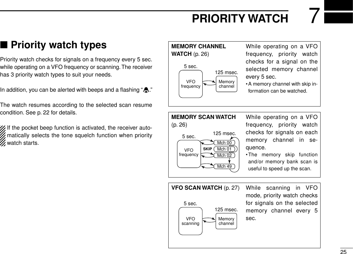
![267PRIORITY WATCH■Priority watch operation◊Memory channel watch and memory scanwatchqSelect VFO mode; then, set an operating frequency.wSet the watching channel(s).For memory channel watch:Select the desired memory channel.For memory scan watch:Select memory mode; then, push [↔] for 2 sec. to startmemory scan.ePush [FUNC] + [(MODE)SET] momentarily to enter setmode.•Select a non-band scope screen in advance for color LCD.rRotate [DIAL] to select “Priority”or “PRIo.”•“PRIo”disappears after 1 sec. and “oFF”and “PR”appears whencolor LCD is OFF.tPush [↔] or rotate the tuning dial while pushing [FUNC] toselect priority watch ON or priority watch ON with alert(BELL).•If the pocket beep function is activated, the receiver automaticallyselects the tone squelch function when the priority watch is se-lected.yPush [(MODE)SET] to exit set mode and start the watch.•The receiver checks the memory channel frequency every 5 sec.•The watch resumes according to the selected scan resume con-dition. (p. 22)•If the priority watch with alert is ON, you can be alerted withbeeps and a flashing “P. B ”or “ë.”•If the direction finding screen is selected, the receiver automati-cally selects the simple screen when the priority watch starts.uPush [V/M] while the display shows the VFO frequency tostop the watch.FM PRIORXS1 3 5 7 9VOLRXFM145.765.000M:A18PRIOTS 15.0 While pausing on the memory channel, “PRIO” flashes.Priority watch setmodePause Scan : 10SECPriority : OFFBeep Audio : VOLUMELight : AUTOA.Power OFF : OFFPause Scan : 10SECPriority : ONBeep Audio : VOLUMELight : AUTOA.Power OFF : OFFPause Scan : 10SECPriority : BELLBeep Audio : VOLUMELight : AUTOA.Power OFF : OFFPriority watch is ON. Priority watch withalert is ON.](https://usermanual.wiki/ICOM-orporated/IC-R3/User-Guide-118953-Page-30.png)
![◊VFO scan watchqSelect the desired memory channel to be watched.wPush [V/M] to select VFO mode.ePush [↔] for 2 sec. to start full scan, band scan or pro-grammed scan. (p. 19)rPush [FUNC] + [(MODE)SET] momentarily to enter setmode.•Select a non-band scope screen in advance for color LCD.tRotate [DIAL] to select “Priority”or “PRIo.”•“PRIo”disappears after 1 sec. and “oFF”and “PR”appears whencolor LCD is OFF.yPush [↔] or rotate the tuning dial while pushing [FUNC] toselect priority watch ON or priority watch ON with alert(BELL).•If the pocket beep function is activated, the receiver automaticallyselects the tone squelch function when the priority watch is se-lected.uPush [(MODE)SET] to exit set mode and start the watch.•The receiver checks the memory channel frequency every 5 sec.•The watch resumes according to the selected scan resume con-dition. (p. 22)•If the priority watch with alert is ON, you can be alerted withbeeps and a flashing “P. B ”or “ë.”•If the direction finding screen is selected, the receiver automati-cally selects the simple screen when the priority watch starts.iPush [V/M] while the display shows the VFO frequency tostop the watch.FM PRIORXS1 3 5 7 9VOLRXFM145.765.000M:A18PRIOALLTS 15.0 While pausing on the memory channel, “PRIO” flashes.Priority watch setmodePause Scan : 10SECPriority : OFFBeep Audio : VOLUMELight : AUTOA.Power OFF : OFFPause Scan : 10SECPriority : ONBeep Audio : VOLUMELight : AUTOA.Power OFF : OFFPause Scan : 10SECPriority : BELLBeep Audio : VOLUMELight : AUTOA.Power OFF : OFFPriority watch is ON. Priority watch withalert is ON.277PRIORITY WATCH](https://usermanual.wiki/ICOM-orporated/IC-R3/User-Guide-118953-Page-31.png)
![288SUBAUDIBLE TONE OPERATION■Tone squelch operation◊OperationThe tone squelch opens only when receiving a signal con-taining a matching subaudible tone. You can silently wait forcalls from group members using the same tone in an ama-teur band.qSet the operating frequency in FM mode.wSet the desired subaudible tone in set mode.•See the following section for programming.ePush [FUNC] + [(MODE)SET] momentarily to enter setmode.•Select a non-band scope screen in advance for color LCD.rRotate [DIAL] until “Tone Squelch”or “tSqL”appears.•“tSqL”disappears after 1 sec. and “to”appears when color LCD isOFF.tPush [↔] or rotate the tuning dial while pushing [FUNC] toselect “TSQL”(tone squelch).yPush [(MODE)SET] to exit set mode and start the tonesquelch.uWhen the received signal includes a matching tone, thesquelch opens and the signal can be heard.•When the received signal’s tone does not match, tone squelchdoes not open, however, the S-indicator shows signal strength.•To open the squelch manually, push and hold [SQL]. (default)iTo cancel the tone squelch, repeat steps e–yas de-scribed above and select “OFF”in step t.◊Setting subaudible tones for tone squelchoperationqSelect VFO mode or desired memory channel to be pro-grammed.•Each operating band and each memory channel have indepen-dent settings.wPush [FUNC] + [(MODE)SET] momentarily to enter setmode.•Select a non-band scope screen in advance for color LCD.eRotate [DIAL] until “Tone Freq.”or “tonE”appears.•“tonE”disappears after 1 sec. and “Ct”appears.rPush [↔] or rotate the tuning dial while pushing [FUNC] toselect a subaudible tone.tPush [(MODE)SET] to exit set mode.Tone function set modeTone Squelch: OFFTone Freq. : 88.5Duplex : OFFOffset Freq.: 0.600 Scan Resume : 2SECTone Squelch: OFFTone Freq. : 88.5Duplex : OFFOffset Freq.: 0.600 Scan Resume : 2SECTone Squelch: TSQLTone Freq. : 88.5Duplex : OFFOffset Freq.: 0.600 Scan Resume : 2SECTone squelch OFF Tone squelch ON](https://usermanual.wiki/ICOM-orporated/IC-R3/User-Guide-118953-Page-32.png)
![•Available subaudible tone frequencies (unit: Hz)"CONVENIENTStore subaudible tone frequencies and tone squelch ON/OFFsettings in memories for easy recall.The receiver has 50 tone frequencies and consequentlytheir spacing is narrow. Therefore, some tone frequenciesmay receive interference from adjacent ones.■Pocket beep operationThis function uses subaudible tones for calling and can beused as a “common pager”to inform you that someone hascalled using the same tone in an amateur band while youwere away from the receiver.◊Waiting for a call from a specific stationqSet the operating frequency in FM mode.wSet the desired tone squelch tone in set mode.•See the previous page for programming information.eTurn the priority watch OFF when used. (p. 26)•The pocket beep cannot be used with the priority watch.rPush [FUNC] + [(MODE)SET] momentarily to enter setmode.•Select a non-band scope screen in advance for color LCD.TSQLTone function set modeTone Squelch: OFFTone Freq. : 88.5Duplex : OFFOffset Freq.: 0.600 Scan Resume : 2SECTone Squelch: OFFTone Freq. : 88.5Duplex : OFFOffset Freq.: 0.600 Scan Resume : 2SECTone Squelch: P BEEPTone Freq. : 88.5Duplex : OFFOffset Freq.: 0.600 Scan Resume : 2SECTone function OFF Pocket beep ONTone frequency set modeTone Squelch: TSQLTone Freq. : 88.5Duplex : OFFOffset Freq.: 0.600 Scan Resume : 2SECTone Squelch: TSQLTone Freq. : 88.5Duplex : OFFOffset Freq.: 0.600 Scan Resume : 2SECTone Squelch: TSQLTone Freq. : 254.1Duplex : OFFOffset Freq.: 0.600 Scan Resume : 2SEC88.5 Hz (default) 254.1 Hz tone298SUBAUDIBLE TONE OPERATION67.069.371.974.477.079.782.585.488.591.594.897.4100.0103.5107.2110.9114.8118.8123.0127.3131.8136.5141.3146.2151.4156.7159.8162.2165.5167.9171.3173.8177.3179.9183.5186.2189.9192.8196.6199.5203.5206.5210.7218.1225.7229.1233.6241.8250.3254.1](https://usermanual.wiki/ICOM-orporated/IC-R3/User-Guide-118953-Page-33.png)
![308SUBAUDIBLE TONE OPERATIONtRotate [DIAL] until “Tone Squelch”or “tSqL”appears.•“tSqL”disappears after 1 sec. and “to”appears when color LCD isOFF.yPush [↔] or rotate the tuning dial while pushing [FUNC] toselect “P BEEP”(pocket beep).uPush [(MODE)SET] to exit set mode and start the pocketbeep.•“P. B ”or “TSQL ë”appears in the function display.iWhen a signal with the correct tone is received, the re-ceiver emits beep tones for 30 sec. and flashes “P.B”or“ë.”oPush [SQL] to stop the beeps and flashing.•Tone squelch is automatically selected.■Tone scanThe receiver can detect the subaudible tone frequency in areceived signal. By monitoring a signal that is being transmit-ted on a frequency, you can check the tone frequency re-quired to access the repeater, or to open the tone squelch.qSet the desired frequency or memory channel to bechecked for a tone frequency.wSelect FM mode with [MODE].ePush [FUNC] + [↔] for 2 sec. to start the tone scan.•To change the scanning direction, rotate [DIAL].rWhen the tone frequency is detected, the set mode con-tents are programmed with the tone frequency.•The tone scan pauses when a tone frequency is detected.•The detected tone frequency is used for the tone squelch fre-quency.•“Ct”appears during tone scan.tPush [↔] to stop the scan.S1 3 5 7 9VOLFM146.1 CT TS 15.0 “Ct” appears during tonescan.Tone frequencies flash as they are scanned.flashes when correct tone is received.TSQLFMPS1 3 5 7 9VOLRXFM P.B146.100.000TS 15.0 RX](https://usermanual.wiki/ICOM-orporated/IC-R3/User-Guide-118953-Page-34.png)
![319DUPLEX OPERATIONDuplex communication uses 2 different frequencies for trans-mitting and receiving. Generally, duplex is used in communi-cation through a repeater, some utility communications, etc.During duplex operation, the transmit station frequency isshifted from the receive station frequency by the offset fre-quency. Repeater information (offset frequency and shift di-rection) can be programmed into memory channels. (p. 14)This function is not available in the broadcast band (0.495–1.620 MHz) except for U.S.A. and Canada versions.qSet the receive station frequency (repeater output fre-quency).wSet the shift direction and offset of the transmit station fre-quency as described below.ePush and hold [SQL] to monitor the transmit station fre-quency (repeater input frequency) directly.◊Duplex shift directionqPush [FUNC] + [(MODE)SET] momentarily to enter setmode.•Select a non-band scope screen in advance for color LCD.wRotate [DIAL] until “Duplex”or “dUP”appears.•“dUP”disappears after 1 sec. and “dP”appears when color LCDis OFF.ePush [↔] or rotate the tuning dial while pushing [FUNC] toselect “–DUP”or “(+)DUP.”•“–DUP”or “(+)DUP”indicates the transmit station frequency forminus shift or plus shift, respectively.rPush [(MODE)SET] to exit set mode.Duplex direction set modeTone Squelch: OFFTone Freq. : 88.5Duplex : OFFOffset Freq.: 0.600 Scan Resume : 2SECTone Squelch: OFFTone Freq. : 88.5Duplex : -DUPOffset Freq.: 0.600 Scan Resume : 2SECTone Squelch: OFFTone Freq. : 88.5Duplex : +DUPOffset Freq.: 0.600 Scan Resume : 2SECMinus shift Plus shiftFMPS1 3 5 7 9VOLFM146.100.000TS 15.0 DUP–DUP](https://usermanual.wiki/ICOM-orporated/IC-R3/User-Guide-118953-Page-35.png)
![329DUPLEX OPERATION◊Offset frequencyDuring duplex operation, the transmit station frequency isshifted from the receive station frequency by an amount de-termined by the offset frequency.qSelect VFO mode or desired memory channel to be pro-grammed.wPush [FUNC] + [(MODE)SET] momentarily to enter setmode.•Select a non-band scope screen in advance for color LCD.eRotate [DIAL] until “Offset Freq.”or “oFFSEt”appears.•“oFFSEt”disappears after 1 sec. and “oW”appears when thecolor LCD is OFF.rPush [↔] or rotate the tuning dial while pushing [FUNC] toset the desired offset.•The offset frequency changes according to the selected tuningstep. (p. 8)tPush [(MODE)SET] to exit set mode.Offset frequency set modeTone Squelch: OFFTone Freq. : 88.5Duplex : OFFOffset Freq.: 0.600 Scan Resume : 2SECTone Squelch: OFFTone Freq. : 88.5Duplex : OFFOffset Freq.: 0.600 Scan Resume : 2SECTone Squelch: OFFTone Freq. : 88.5Duplex : OFFOffset Freq.: 7.600 Scan Resume : 2SEC0.6 MHz (600 kHz) offset 7.6 MHz offset](https://usermanual.wiki/ICOM-orporated/IC-R3/User-Guide-118953-Page-36.png)
![3310BAND SCOPEThe band scope function allows you to visually check a spec-ified frequency range. Sweep range can be selected from ±5kHz through ±500 kHz.Receive audio is muted while monitoring the band scope.Push [SQL] to cancel sweeping and receive the audio.qPush [FUNC] + [↕] for 2 sec. to turn the color LCD ON.wPush [FUNC] + [↕] one or more times to select the bandscope screen.eSet the desired frequency as band scope center frequency.rPush [FUNC] + [V/M] momentarily to select the sweeprange, if desired.•5, 10, 20, 100 and 500 kHz sweep ranges are available.tPush [FUNC] + [V/M] momentarily to start a sweep onceor push them for 2 sec. to start sweeping continuously.•Signal conditions (strengths) appear starting from the center ofthe range.•Push [SQL] to cancel sweeping.yRotate [DIAL] to set the highlighted cursor to the desiredwaveform and set the frequency of the signal.•Start sweeping to set the selected frequency to the center fre-quency.FM146.100.000 TS= 25.0 SWEEP-500kS1 3 5 7 9 VOLSweep range](https://usermanual.wiki/ICOM-orporated/IC-R3/User-Guide-118953-Page-37.png)
![3411 TV OPERATION■TV operationThe receiver can receive TV (NTSC or PAL depending on ver-sion). TV channels are preset depending on versions.The received video and audio can be output from [A/V OUT] ifdesired.◊TV channel receivingqPush [FUNC] + [↕] for 2 sec. to turn the color LCD ON, ifdesired.•Only the audio part of the TV contents can be received.wPush [↔] one or more times to select the TV channelband.•“tV”and channel number appear in the sub LCD.•The squelch is automatically opened. Push [SQL] to toggle be-tween squelch open and audio mute conditions.eRotate [DIAL] to select the desired channel.•Rotate [DIAL] while pushing [FUNC] to select the skip channel.◊Skip channel settingUnwanted channels can be skipped for rapid selection, etc.qRotate [DIAL] to select the channel to be skipped.•To clear the skip setting, rotate [DIAL] while pushing [FUNC] toselect a skip channel.wWhile pushing [FUNC], push [(V/M)SKIP] for 2 sec. to tog-gle the condition between non-skip and skip channel.•No indication : channel will not be skipped.•“"”appears : channel skipped during selection.To select a skip TV channel temporarily, rotate [DIAL] whilepushing [FUNC].◊Automatic TV channel programmingTV channels can be programmed automatically.qPush [FUNC] + [↔] for 2 sec. to start TV channel pro-gramming.wThe programming will automatically stop after scanning allchannels.FMWRX](https://usermanual.wiki/ICOM-orporated/IC-R3/User-Guide-118953-Page-38.png)
![3511TV OPERATION◊TV frequency (AM TV) receivingYou can set the TV frequency instead of channel selection, ifdesired.qPush [FUNC] + [↕] for 2 sec. to turn the color LCD ON, ifdesired.•The audio part of the TV contents can be received when thecolor LCD is turned OFF.wPush [↔] one or more times to select the band above 30MHz.•TV receiving does not function for less than 30 MHz.ePush [FUNC] + [↕] one or more times to select the TVscreen.•“tV”and frequency appear in the sub LCD.•The squelch is automatically opened. Push [SQL] to toggle be-tween squelch open and audio mute conditions.rRotate [DIAL] to set the desired frequency.•Push [↔] one or more times to select the band.•Rotate [DIAL] while pushing [FUNC] for dial select step. (p. 39)◊TV frequency (AM TV) memory channelThe receiver has 10 memory channels for storage of often-used TV (AM TV) frequencies.qSet the desired frequency with [DIAL].•Push [↔] one or more times to select the band.•Rotate [DIAL] while pushing [FUNC] for dial select step. (p. 39)wPush [V/M] for 1 sec. to indicate memory channels.•Do not hold [V/M] for more than 2 sec., otherwise the previouslyselected memory channel will be overwritten.eRotate [DIAL] to select the desired channel.rPush [V/M] for 1 sec. to program.•Keep pushing for 2 sec. or more to automatically select the nextmemory channel, if desired.Memory programming after selection, memory transferringor memory clearing can be used as same manner of regu-lar memory channels. (pgs. 15, 16)FMWRXFMWRX](https://usermanual.wiki/ICOM-orporated/IC-R3/User-Guide-118953-Page-39.png)
![3611 TV OPERATION■ATV operationThe IC-R3 ATV-type can receive an amateur TV (FM TV)within 900–1300 and 2250–2450.095 MHz. The receivedvideo and audio can be output from [A/V OUT] if desired. (p.5)qPush [FUNC] + [↕] for 2 sec. to turn the color LCD ON, ifdesired.•Only the audio part of the TV contents can be received.wPush [↔] one or more times to select the 1200 or 2400MHz bands.ePush [FUNC] + [↕] one or more times to select the ama-teur TV screen.•“FtV”and frequency appear in the sub LCD.•The squelch is automatically opened. Push [SQL] to toggle be-tween squelch open and audio mute conditions.rRotate [DIAL] to set the desired frequency.The video display mode can be selected as positive andnegative depending on the received signal. Push [MODE]to toggle the display mode, if desired.◊ATV memory channelThe receiver has 50 memory channels for storage of often-used ATV (Amateur TV) frequencies.qSet the desired frequency with [DIAL].•Push [↔] to select the 1200 or 2400 MHz band.•Rotate [DIAL] while pushing [FUNC] for dial select step. (p. 39)wPush [V/M] for 1 sec. to indicate memory channels.•Do not hold [V/M] for more than 2 sec., otherwise the previouslyselected memory channel will be overwritten.eRotate [DIAL] to select the desired channel.rPush [V/M] for 1 sec. to program.•Keep pushing for 2 sec. or more toautomatically select the next mem-ory channel, if desired.Memory programming after selection, memory transferringor memory clearing can be used as same manner of regu-lar memory channels. (pgs. 15, 16)◊Sub carrier adjustmentqPush [FUNC] + [↔] for 2 sec. to enter sub carrier setmode.wPush [↔] or rotate the tuning dialwhile pushing [FUNC] to adjustsub carrier for better audio re-ceiving.ePush [↔] to exit sub carrier set mode.FMWRXFMWRXRX](https://usermanual.wiki/ICOM-orporated/IC-R3/User-Guide-118953-Page-40.png)
![3712DIRECTION FINDINGThe direction finding function allows you to check a variationof the signal level continuously.Using a commercially available directional antenna, you candetermine the direction of the signal source. Using 2 receiverswith the directional antennas, you can pinpoint the signalsource.qPush [FUNC] + [↕] for 2 sec. to turn the color LCD ON.wPush [FUNC] + [↕] one or more times to select the directionfinding screen.eSet the desired frequency.•The color LCD shows the variation of the signal level.•If the strong signal is received on 1149.995 MHz or below, usethe attenuator function. (p. 9)rTurn around the directional antenna for maximum receivelevel.tThe direction (or opposite) of the maximum receive levelmay indicate the signal source direction.•Direction finding function exampleThe direction finding function is a supplemental aid for find-ing a signal source only. It is not designed for use as acompass.FM146.100.00015.0 TSSignal sourceIC-R3SignallevelsTimeFM146.100.00015.0 TSSignal levels](https://usermanual.wiki/ICOM-orporated/IC-R3/User-Guide-118953-Page-41.png)
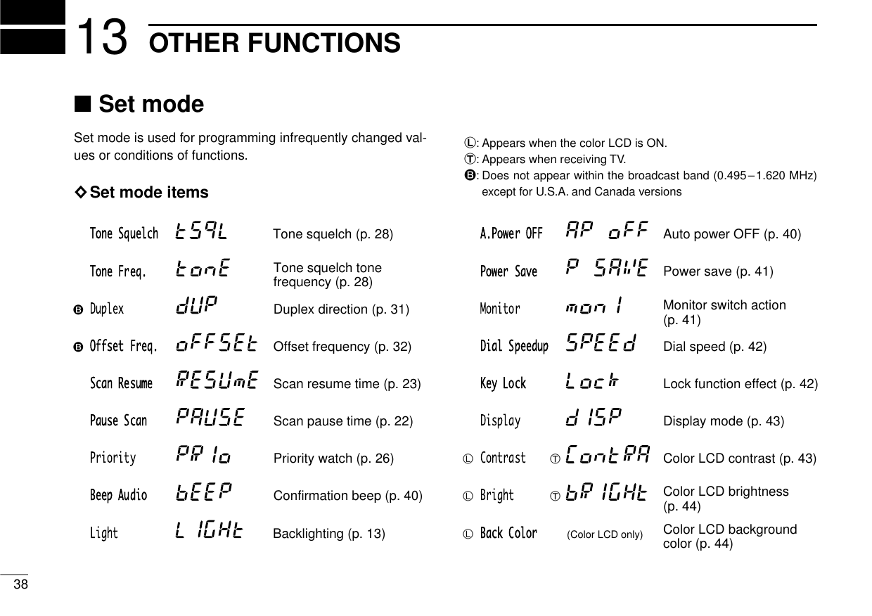
![3913OTHER FUNCTIONS■Dial select stepThis receiver has a 1 MHz tuning step for quick frequency set-ting. This dial select step can be set to 100 kHz, 1 MHz or 10MHz steps, as desired.The selected dial select step is always displayed in the sim-ple, multi-function and direction finding screen in the colorLCD.This function is not available to the broadcast band (0.495–1.620 MHz) except for U.S.A. and Canada versions.◊Setting dial select stepqSelect VFO mode with [V/M].wPush [FUNC] + [↔] momentarily to enter dial select stepsetting condition.•“8”appears to the selected dial select step.eWhile continuously pushing [FUNC], push [↔] to select thedesired dial select step.•100 kHz, 1 MHz and 10 MHz steps are available.rRelease [FUNC] to exit the condition.S1 3 5 7 9VOLFM.8 . TS 15.0 S1 3 5 7 9VOLFM8. . TS 15.0 S1 3 5 7 9VOLFM8 . . TS 15.0 1 MHz step100 kHz step 10 MHz stepS1 3 5 7 9VOLFM144.765.000TS 15.0 1 MHz dial select stepis selected.](https://usermanual.wiki/ICOM-orporated/IC-R3/User-Guide-118953-Page-43.png)
![4013 OTHER FUNCTIONS■Beep tonesThe volume level for confirmation beep tones, which soundeach time a switch is pushed, can be adjusted, as desired.When “VOLUME”is selected, the beep tone volume level islinked with the receive volume level.qPush [FUNC] + [(MODE)SET] momentarily to enter setmode.•Select a non-band scope screen in advance for color LCD.wRotate [DIAL] until “Beep Audio”or “bEEP”appears.•“bEEP”disappears after 1 sec. and “bE”appears when color LCDis OFF.ePush [↔] or rotate the tuning dial while pushing [FUNC] toset the volume level.rPush [(MODE)SET] to exit set mode.■Auto power-off functionThe receiver can be set to automatically turn OFF after aspecified period with beep in which no switch is pushed.120 min., 90 min., 60 min., 30 min. and OFF can be speci-fied. The specified period is retained even when the receiveris turned OFF by the auto power-off function. To cancel thefunction, select “OFF”in step ebelow.qPush [FUNC] + [(MODE)SET] momentarily to enter setmode.•Select a non-band scope screen in advance for color LCD.wRotate [DIAL] until “A.Power OFF”or “AP oFF”appears.•“AP oFF”disappears after 1 sec. and “Ao”appears when colorLCD is OFF.ePush [↔] or rotate the tuning dial while pushing [FUNC] toselect the desired time or to turn the function OFF.rPush [(MODE)SET] to exit set mode.60 min. auto power-offAuto power off setmode Auto power-off isturned OFF.Beep tone is turnedOFF (minimum).Beep tone is turned ON and linked with the volume level.Beep tone is fixed to the set level.Pause Scan : 10SECPriority : OFFBeep Audio : VOLUMELight : AUTOA.Power OFF : OFFPause Scan : 10SECPriority : OFFBeep Audio : ______Light : AUTOA.Power OFF : OFFPause Scan : 10SECPriority : OFFBeep Audio : OOO___Light : AUTOA.Power OFF : OFF](https://usermanual.wiki/ICOM-orporated/IC-R3/User-Guide-118953-Page-44.png)
![4113OTHER FUNCTIONS■Power saverThe power saver function reduces the current drain to con-serve battery power.qPush [FUNC] + [(MODE)SET] momentarily to enter setmode.•Select a non-band scope screen in advance for color LCD.wRotate [DIAL] until “Power Save”or “P SAVE”appears.•“P SAVE”disappears after 1 sec. and “PS”appears when colorLCD is OFF.ePush [↔] or rotate the tuning dial while pushing [FUNC] toturn the power saver ON (AUTO) or OFF.rPush [(MODE)SET] to exit set mode.■Monitor switch actionThe monitor switch can be set as a ‘sticky’switch. When set tothe sticky condition, each push of [SQL] toggles the monitorfunction on and off.qPush [FUNC] + [(MODE)SET] momentarily to enter setmode.•Select a non-band scope screen in advance for color LCD.wRotate [DIAL] until “Monitor”or “monI”appears.•“monI”disappears after 1 sec. and “mo”appears when color LCDis OFF.ePush [↔] or rotate the tuning dial while pushing [FUNC] toset the monitor switch to sticky (HOLD) or normal (PUSH).rPush [(MODE)SET] to exit set mode.‘Sticky’ actionMonitor switch function set mode ‘Normal’ actionPower Save : AUTOMonitor : PUSHDial Speedup: ONKey Lock : NORMALDisplay : AUTOPower Save : AUTOMonitor : HOLDDial Speedup: ONKey Lock : NORMALDisplay : AUTOPower Save : AUTOMonitor : PUSHDial Speedup: ONKey Lock : NORMALDisplay : AUTOPower saver ON(AUTO)Power save setmode Power saver OFFPower Save : AUTOMonitor : PUSHDial Speedup: ONKey Lock : NORMALDisplay : AUTODial Speedup: ONKey Lock : NORMALDisplay : AUTODial Speedup: ONKey Lock : NORMALDisplay : AUTOPower Save : AUTOMonitor : PUSH Power Save : OFFMonitor : PUSH](https://usermanual.wiki/ICOM-orporated/IC-R3/User-Guide-118953-Page-45.png)
![4213 OTHER FUNCTIONS■Dial speed accelerationThe dial speed acceleration automatically speeds up the tun-ing dial speed when rotating the [DIAL] rapidly.qPush [FUNC] + [(MODE)SET] momentarily to enter setmode.•Select a non-band scope screen in advance for color LCD.wRotate [DIAL] until “Dial Speedup”or “SPEEd”appears.•“SPEEd”disappears after 1 sec. and “SP”appears.ePush [↔] or rotate the tuning dial while pushing [FUNC] toset the dial speed acceleration ON or OFF.rPush [(MODE)SET] to exit set mode.■Lock function effectThe lock function prevents accidental frequency changes andaccidental function access.While the lock function is ON, [POWER], [VOL (↕)] and [SQL]can still be accessed. Accessible switches can be set to 1 of 4groups in set mode.qPush [FUNC] + [(MODE)SET] momentarily to enter setmode.•Select a non-band scope screen in advance for color LCD.wRotate [DIAL] until “Key Lock”or “LoCk”appears.•“LoCk”disappears after 1 sec. and “Lk”appears.ePush [↔] or rotate the tuning dial while pushing [FUNC] toselect the accessible switches.•“NORMAL”:[POWER], [VOL] and [SQL] are accessible.•“NO SQL”:[POWER] and [SQL] are accessible.•“NO VOL”:[POWER] and [VOL] are accessible.•“ALL”:[POWER] is accessible.rPush [(MODE)SET] to exit set mode.Lock function effectset mode [POWER], [VOL] and [SQL] areaccessible.[POWER] and [SQL]are accessible.Power Save : AUTOMonitor : PUSHDial Speedup: ONKey Lock : NORMALDisplay : AUTOPower Save : AUTOKey Lock : NORMALDisplay : AUTOPower Save : AUTOKey Lock : NORMALDisplay : AUTODial speed accelerationset modeDial speed acceleration ON Dial speed acceleration OFFMonitor : PUSHDial Speedup: ON Monitor : PUSHDial Speedup: OFF](https://usermanual.wiki/ICOM-orporated/IC-R3/User-Guide-118953-Page-46.png)
![4313OTHER FUNCTIONS■Display mode selectionThe color LCD can be automatically turned ON when usingwith the external DC power (CP-18A/E or commercially availableDC power supply; 5.5–6.3 V DC with more than 4 A capacity).qPush [FUNC] + [(MODE)SET] momentarily to enter setmode.•Select a non-band scope screen in advance for color LCD.wRotate [DIAL] until “Display”or “dISP”appears.•“dISP”disappears after 1 sec. and “dI”appears.ePush [↔] or rotate the tuning dial while pushing [FUNC] toset the color LCD mode to automatic (AUTO) or manual.•The color LCD will be turned OFF after setting.rPush [(MODE)SET] to exit set mode.■Display contrastThis item adjusts the contrast of the color LCD from 0 % to100 % in 32 steps.qPush [FUNC] + [↕] for 2 sec. to turn the color LCD ON.wPush [FUNC] + [(MODE)SET] momentarily to enter setmode.•Select a non-band scope screen in advance.eRotate [DIAL] until “Contrast”or “ContRA”appears.•“ContRA”disappears after 1 sec. and “co”appears.rPush [↔] or rotate the tuning dial while pushing [FUNC] toadjust the contrast of the color LCD.tPush [(MODE)SET] to exit set mode.RX RX RX50% (default)Display contrast setmode 25%Key Lock : NORMALDisplay : AUTOContrast : 50%Bright : 50%Back Color : 4Key Lock : NORMALBright : 50%Back Color : 4Key Lock : NORMALBright : 50%Back Color : 4Display : AUTOContrast : 50% Display : AUTOContrast : 25%Manual selectionDisplay mode set mode Automatic selectionKey Lock : NORMALDisplay : AUTOContrast : 50%Bright : 50%Back Color : 4Key Lock : NORMALDisplay : MANUALContrast : 50%Bright : 50%Back Color : 4Key Lock : NORMALDisplay : AUTOContrast : 50%Bright : 50%Back Color : 4](https://usermanual.wiki/ICOM-orporated/IC-R3/User-Guide-118953-Page-47.png)
![4413 OTHER FUNCTIONS■Display brightnessThis item adjusts the brightness of the color LCD from 0 % to100 % in 32 steps.qPush [FUNC] + [↕] for 2 sec. to turn the color LCD ON.wPush [FUNC] + [(MODE)SET] momentarily to enter setmode.•Select a non-band scope screen in advance.eRotate [DIAL] until “Bright”appears.•“bRIGHt”disappears after 1 sec. and “bR”appears.rPush [↔] or rotate the tuning dial while pushing [FUNC] toadjust the brightness of the color LCD.tPush [(MODE)SET] to exit set mode.■Display background colorThis item selects the background color of the color LCD from8 colors.qPush [FUNC] + [↕] for 2 sec. to turn the color LCD ON.wPush [FUNC] + [(MODE)SET] momentarily to enter setmode.•Select a non-band scope screen in advance.eRotate [DIAL] until “Back Color”appears.rPush [↔] or rotate the tuning dial while pushing [FUNC] toselect the background color.•0 black 4 blue1 pink 5 purple2 green 6 lime3 orange 7 whitetPush [(MODE)SET] to exit set mode.4 (default) 1 (black)Key Lock : NORMALBright : 50%Key Lock : NORMALBright : 50%Display : AUTO Display : AUTOContrast : 50%Back Color : 4Contrast : 50%Back Color : 1RX RX RX50% (default)Display brightness set mode 25%Key Lock : NORMALDisplay : AUTOContrast : 50%Bright : 50%Back Color : 4Key Lock : NORMALBack Color : 4Key Lock : NORMALBack Color : 4Display : AUTO Display : AUTOContrast : 50%Bright : 50% Contrast : 50%Bright : 25%](https://usermanual.wiki/ICOM-orporated/IC-R3/User-Guide-118953-Page-48.png)
![4513OTHER FUNCTIONS■Cloning functionThe IC-R3 has receiver-to-receiver data cloning capability.This function is useful when you want to copy all of the pro-grammed contents from one IC-R3 to another. An optionalOPC-474 CLONING CABLE is required.The optional CS-R3 CLONING SOFTWARE and the optionalOPC-478 CLONING CABLE are available to clone and editcontents with a PC (for Microsoft®Windows®95 and 98).qWhile pushing [MODE] and ó[UP], push [POWER] for 2sec. to enter cloning mode.•“CLonE”appears.wConnect an optional OPC-474 between both [SP] jacks.ePush [SQL] on the “mas-ter”receiver (receiver-to-receiver cloning only).•“oUt”appears and the signalindicator shows that cloningis taking place.rPush [POWER] for 2 sec.to turn power OFF.Microsoft®and Windows®are regis-tered trademarks of Microsoft Corpo-ration in the U.S.A and othercountries.■Partial resetIf you want to initialize the operating conditions (VFO fre-quency, VFO settings, set mode contents) without clearing thememory contents, a partial resetting function is available forthe receiver.➥While pushing [FUNC] and [V/M], turn power ON to par-tially reset the receiver.■Total resetReset the CPU before operating the receiver for the first time,or when the internal CPU malfunctions.➥While pushing [FUNC], [V/M] and [MODE], turn power ONto reset the CPU.•“CLEAR”appears in the sub LCD when resetting the CPU.CAUTION: Resetting the CPU returns all programmedcontents to their default settings.OPC-474](https://usermanual.wiki/ICOM-orporated/IC-R3/User-Guide-118953-Page-49.png)
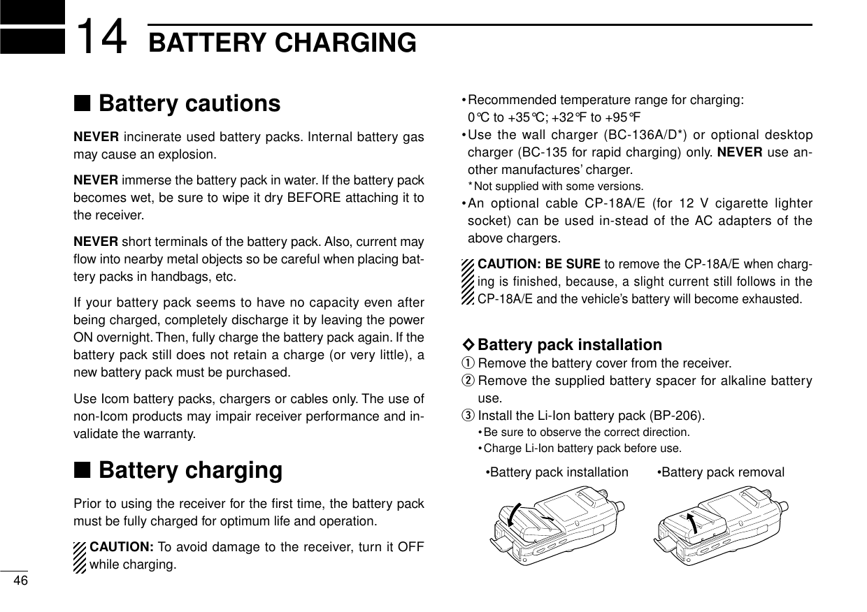
![4714BATTERY CHARGING◊Regular chargingqAttach the battery pack to the receiver.wBe sure to turn the receiver power OFF.eConnect the AC adapter (BC-136A/D*) or optional cable(CP-18A/E) as shown below.*Not supplied with some versions.rRemove any cables from the [DC 6V] jack.•Charging periods: 15 hours (w/BP-206)◊CP-18A/E fuse replacement◊Rapid charging with the BC-135The optional BC-135 provides rapid charging of batterypacks.•Charging periods: 2.5 hours (w/BP-206)CAUTION: Shorten or remove the telescoping antenna be-fore charging to prevent the receiver from overturning.If the charge indicator flashes orange, there may be aproblem with the battery pack (or charger). Re-insert thebattery pack or contact your dealer.Turn power OFF.BC-135Check the orientation.Shorten or remove the antenna.IC-R3 with BP-206BC-136A/DCP-18A/E(optional)BE SURE to remove CP-18A/Ewhen charging is finished.To[DC 6V]CP-18A/EFuse 5 A](https://usermanual.wiki/ICOM-orporated/IC-R3/User-Guide-118953-Page-51.png)
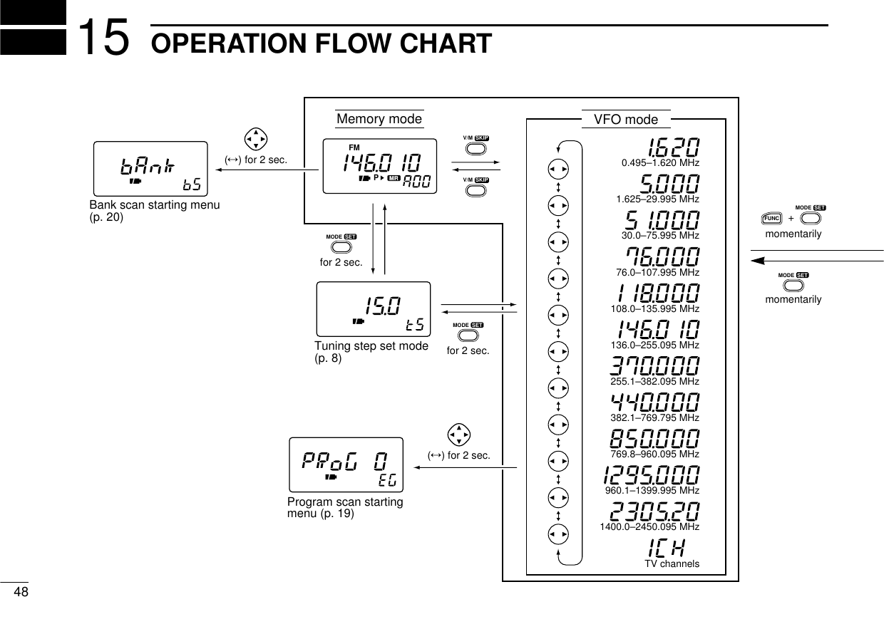
![4915OPERATION FLOW CHARTTone squelch (p. 28)Tone squelch tone frequency (p. 28)B Duplex direction (p. 31)B Offset frequency (p. 32)Scan resume time (p. 23)Scan pause time (p. 22)Priority watch (p. 26)Confirmation beep (p. 40)Backlighting (p. 13)Auto power OFF (p. 40)Power save (p. 41)Monitor switch action (p. 41)Dial speed (p. 42)Lock function effect (p. 42)Color LCD function (p. 43)Color LCD contrast (p. 43)Color LCD brightness (p. 44)L Color LCD background color (p. 44)Set modeB: Does not appear within the broadcast band (0.495 – 1.620 MHz).L: Appears when the color LCD is ON.Displays for set modes show the default settings.Push [↔] or rotate the tuning dial while pushing [FUNC] tochange the set mode condition.](https://usermanual.wiki/ICOM-orporated/IC-R3/User-Guide-118953-Page-53.png)
![5618 TROUBLESHOOTINGPROBLEM POSSIBLE CAUSE SOLUTION REF.No power comes ON. •The batteries are exhausted.•The battery polarity is reversed.•Replace the batteries or charge the battery pack.•Check the battery polarity.pgs. 1,46p. 1No sound comes from thespeaker.•Volume level is too low.•The squelch level is set too tight.•Different tone is selected with tone squelch.•Push ó[UP] to obtain a suitable level.•Open the squelch.•Check the tone using tone scan.p. 11p. 11p. 30Frequency cannot be set. •The lock function is activated. •Push [FUNC] + [MODE(SET)] for 2 sec. to cancel thefunction.p. 9No beeps sound. •Beep tones are turned OFF or the beep tonelevel is low.•Turn beep tones ON or set the beep tone level toappropriate level in set mode.p. 40Receive audio isdistorted.•The operating mode is not selected correctly. •Push [MODE] to select a suitable operating mode. p. 12Desired set mode itemcannot be selected.•Some set mode items can be selected onlywhen the color LCD is ON.•Some set mode items cannot be selected inthe broadcast band.•Turn the color LCD ON.•Choose a band other than the broadcast band.pgs. 6,38p. 38If your receiver seems to be malfunctioning, please check thefollowing points before sending it to a service center.](https://usermanual.wiki/ICOM-orporated/IC-R3/User-Guide-118953-Page-60.png)
![OPERATING GUIDEiR3■BASIC OPERATIONqPush [POWER] for 2 sec.wPush [↕] to set the desired audiolevel.eSelect VFO mode with [V/M].rSelect the desired band with [↔].tRotate [DIAL] to change the fre-quency.•The frequency changes according tothe preset tuning steps.ySet the squelch level.•While pushing [SQL], rotate [DIAL].•The first click of [DIAL] indicates thecurrent squelch level.•“LEVEL1”is loose squelch and“LEVEL9”is tight squelch.•“AUTO”indicates automatic level ad-justment.tWhen a signal is received:•Squelch opens and audio is emittedfrom the speaker.•The S/RF indicator shows the relativesignal strength.◊Using the dial select step (p. 39)Rotate [DIAL] while pushing [FUNC]to change the frequency in 100 kHz,1 MHz or 10 MHz steps.■DUPLEX OPERATIONqSet the receive station frequency(e.g. repeater output frequency).wSet the shift direction of the trans-mit station frequency in set mode.(–DUP or DUP)ePush and hold [SQL] to monitorthe transmit station’s frequency.◊Tone scan (p. 30)Push [FUNC] + [↔] for 2 sec. to startthe tone scan.■MEMORY CHANNEL SELECTIONqPush [V/M] to select memorymode.•“M:”or “X”appears.wSelect a memory channel with[DIAL].eRotate [DIAL] while pushing[FUNC] to select the memorybank.■MEMORY CLEARqSelect the desired memory chan-nel.wSelect VFO mode with [V/M] andpush [V/M] for 1 sec. to indicatethe channel.ePush [FUNC] + [V/M] for 2 sec.Important operating instructions are summed up in this and the following pagefor your simple reference.By cutting along the line and folding on the dotted line, it will become a cardsized operating guide which can easily be carried in a card case or wallet,etc.q Cut w Fold e Complete<CUT HERE>5719QUICK REFERENCE](https://usermanual.wiki/ICOM-orporated/IC-R3/User-Guide-118953-Page-61.png)
![5819 QUICK REFERENCE■SCAN◊Full/band/programmed scanqSelect VFO mode with [V/M].wMake sure the squelch is set tothe threshold point.ePush [↔] for 2 sec. to start thescan.•Rotate [DIAL] while pushing [↔] toselect scan edge, if desired.•To change the scanning direction, ro-tate [DIAL].rPush [↔] again to stop the scan.◊Memory (bank) scanqSelect memory mode with [V/M].wMake sure the squelch is set tothe threshold point.ePush [↔] for 2 sec. to start thescan.•Rotate [DIAL] while pushing [↔] toturn memory bank scan ON or OFF,if desired.rPush [↔] again to stop the scan.■SET MODEqPush [FUNC] + [(MODE)SET]momentarily to enter set mode.•Select non-band scope screen in ad-vance for color LCD.wRotate [DIAL] to select a display.ePush [↔] or rotate [DIAL] whilepushing [FUNC] to set the condi-tion.rPush [(MODE) SET] to exit setmode.■LOCK FUNCTIONPush [FUNC] + [(MODE)SET] for 2sec. to toggle the lock function ON orOFF. (p. 9)■CPU RESETTING◊Partial resetting (p. 45)While pushing [FUNC] and [V/M],turn power on to partially reset thereceiver.•Partial resetting does not clear the mem-ory channel contents.◊Total resetting (p. 45)While pushing [FUNC], [V/M] and[MODE], turn power on to reset thereceiver.Caution: Resetting the receiverinitializes all memory contents.](https://usermanual.wiki/ICOM-orporated/IC-R3/User-Guide-118953-Page-62.png)