ICOM orporated IC-R3 Scanning Receiver User Manual IC R3 2
ICOM Incorporated Scanning Receiver IC R3 2
Manual

INSTRUCTION MANUAL
This device complies with Part 15 of the FCC rules. Operation is sub-
ject to the following two conditions: (1) This device may not cause
harmful interference, and (2) this device must accept any interference
received, including interference that may cause undesired operation.
iR3
COMMUNICATIONS RECEIVER
i
FOREWORD
READ ALL INSTRUCTIONS carefully and completely
before using the receiver.
SAVE THIS INSTRUCTION MANUAL —This in-
struction manual contains important operating instructions for
the IC-R3.
EXPLICIT DEFINITIONS
The explicit definitions below apply to this instruction manual.
CAUTIONS
RWARNING! NEVER operate the receiver with a head-
set or other audio accessories at high volume levels. Hearing
experts advise against continuous high volume operation. If
you experience a ringing in your ears, reduce the volume level
or discontinue use.
AVOID using or placing the receiver in direct sunlight or in
areas with temperatures below –10°C (+14°F) or above
+60°C (+140°F).
Even when the receiver power is OFF, a slight current still
flows in the circuits. Remove batteries from the receiver when
not using it for a long time, otherwise, the installed batteries
will become exhausted.
REMOVE any cables from the [DC 6V] jack after operation or
charging a battery pack.
LCDs are produced using high-density manufacturing tech-
nology resulting in 99.98% active dots, however, up to 0.02%
of the dots may be non-active and/or continuously active. This
is normal and does not indicate LCD malfunction.
For U.S.A. only
CAUTION: Changes or modifications to this device, not ex-
pressly approved by Icom Inc., could void your authority to
operate this device under FCC regulations.
WORD
R
WARNING
CAUTION
NOTE
DEFINITION
Personal injury, fire hazard or electric
shock may occur.
If disregarded, inconvenience only. No risk
of personal injury, fire or electric shock.
Equipment damage may occur.
Versions of the IC-R3 which display the “CE”symbol on the serial
number seal, comply with the essential requirements of the Euro-
pean Radio and Telecommunication Terminal Directive 1999/5/EC.
ii
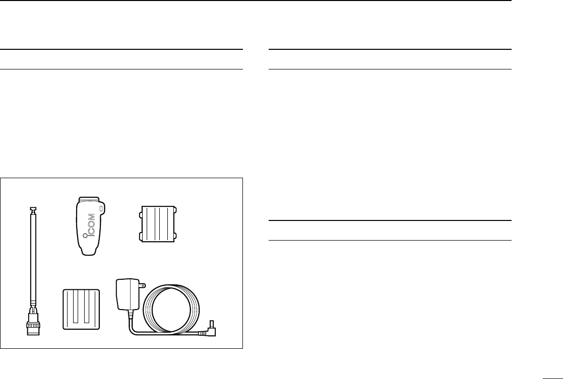
SUPPLIED ACCESSORIES
Accessories included with the receiver: Qty.
qAntenna (FA-B03RE) ...................................................... 1
wBelt clip ........................................................................... 1
eBattery spacer ................................................................ 1
rBattery pack* (BP-206) .................................................. 1
tWall charger* (BC-136A/D) ............................................ 1
*Not supplied with some versions.
OPERATING THEORY
Electromagnetic radiation which has frequencies of 20,000
Hz (20 kHz*) and above is called radio frequency (RF) energy
because it is useful in radio transmissions. The IC-R3 re-
ceives RF energy from 0.495 MHz* to 2450.00 MHz and con-
verts it into audio frequency (AF) energy which in turn
actuates a loudspeaker to create sound waves. AF energy is
in the range of 20 to 20,000 Hz.
*kHz is an abbreviation of kilohertz or 1000 hertz, MHz is abbrevia-
tion of megahertz or 1,000,000 hertz, where hertz is a unit of fre-
quency.
OPERATING NOTES
The IC-R3 may receive its own oscillated frequency, resulting
in no reception or only noise reception, on some frequencies.
The IC-R3 may receive interference from extremely strong
signals on different frequencies or when using an external
high-gain antenna.
qw e
tr

1 ACCESSORY ATTACHMENT ............ 1
2 PANEL DESCRIPTION .................. 2–6
■Panel description ............................. 2
■Function display ............................... 4
■Dual LCD ......................................... 6
3 FREQUENCY AND CHANNEL
SETTING ....................................... 7–9
■VFO and memory channels ............. 7
■Operating band selection ................. 7
■Setting a frequency .......................... 8
■Setting a tuning step ........................ 8
■Selecting a memory channel ........... 9
■Lock function .................................... 9
■Attenuator function ........................... 9
4 BASIC OPERATION .................. 10–13
■Receiving ....................................... 10
■Setting volume level ....................... 11
■Setting squelch level ...................... 11
■Monitor function ............................. 12
■Receive mode selection ................. 12
■Display backlighting ....................... 13
5 MEMORY CHANNELS............... 14–17
■General .......................................... 14
■Programming during selection ....... 14
■Programming after selection .......... 15
■Transferring memory contents to
another memory ............................ 15
■Memory bank selection .................. 16
■Memory clear ................................. 16
■Memory names .............................. 17
6 SCAN OPERATION ................... 18–24
■Scan types ..................................... 18
■Full/band/programmed scan .......... 19
■Memory (bank) scan ...................... 20
■Selecting scan edges ..................... 21
■Skip channel setting ....................... 22
■Scan resume condition .................. 22
■Frequency skip function ................. 24
7 PRIORITY WATCH .................... 25–27
■Priority watch types ....................... 25
■Priority watch operation ................. 26
8 SUBAUDIBLE TONE
OPERATION .............................. 28–30
■Tone squelch operation .................. 28
■Pocket beep operation ................... 29
■Tone scan ...................................... 30
9 DUPLEX OPERATION .............. 31–32
10 BAND SCOPE .................................. 33
11 TV OPERATION ........................ 34–36
■TV operation .................................. 34
■ATV operation ................................ 36
12 DIRECTION FINDING ...................... 37
13 OTHER FUNCTIONS ................. 38–45
■Set mode ....................................... 38
■Dial select step .............................. 39
■Beep tones ..................................... 40
■Auto power-off function .................. 40
■Power saver ................................... 41
■Monitor switch action ..................... 41
■Dial speed acceleration ................. 42
■Lock function effect ........................ 42
■Display mode selection .................. 43
■Display contrast ............................. 43
■Display brightness ......................... 44
■Display background color ............... 44
■Cloning function ............................. 45
■Partial reset .................................... 45
■Total reset ...................................... 45
14 BATTERY CHARGING .............. 46–47
■Battery cautions ............................. 46
■Battery charging ............................ 46
15 OPERATION FLOW CHART.......48–49
16 TV FREQUENCY TABLE ...........50–53
17 SPECIFICATIONS AND
OPTIONS ................................... 54–55
18 TROUBLESHOOTING ...................... 56
19 QUICK REFERENCE .................57–58
iii
TABLE OF CONTENTS
1
1
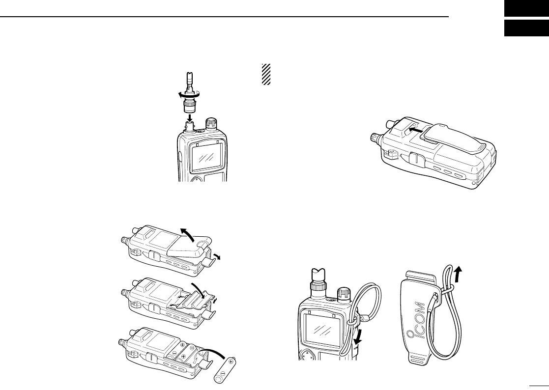
ACCESSORY ATTACHMENT
◊Antenna
Insert the supplied antenna into the an-
tenna connector and screw down the an-
tenna as shown at right.
Keep the jack cover attached when jack
is not in use to avoid bad contacts from
dust and moisture.
Commercially available antennas (BNC)
may increase receiver performance.
◊
Battery installation
qRemove the battery
cover from the receiver.
wFor alkaline battery use,
attach the supplied bat-
tery spacer.
eInstall 3 R6 (AA) size al-
kaline batteries or Li-Ion
battery pack (BP-206; p.
46).
•Be sure to observe the cor-
rect polarity.
•Charge Li-Ion battery pack
before use.
Keep battery contacts clean. It’s a good idea to clean bat-
tery terminals once a week.
◊Belt clip
Conveniently attaches to
your belt.
Slide the belt clip into the
plastic loop on the back
of the receiver.
◊Handstrap (not supplied from Icom)
Slide a commercially available handstrap through the loop on
the side of the receiver or belt clip as illustrated below. Facili-
tates carrying.
q
w
e
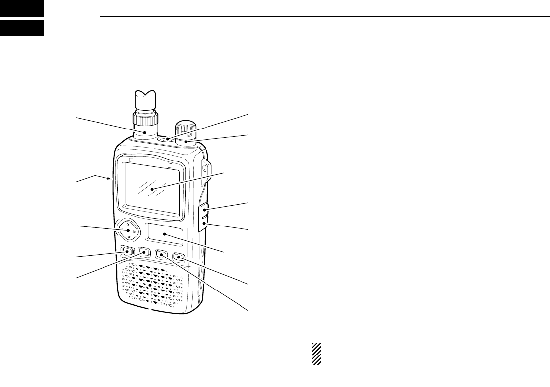
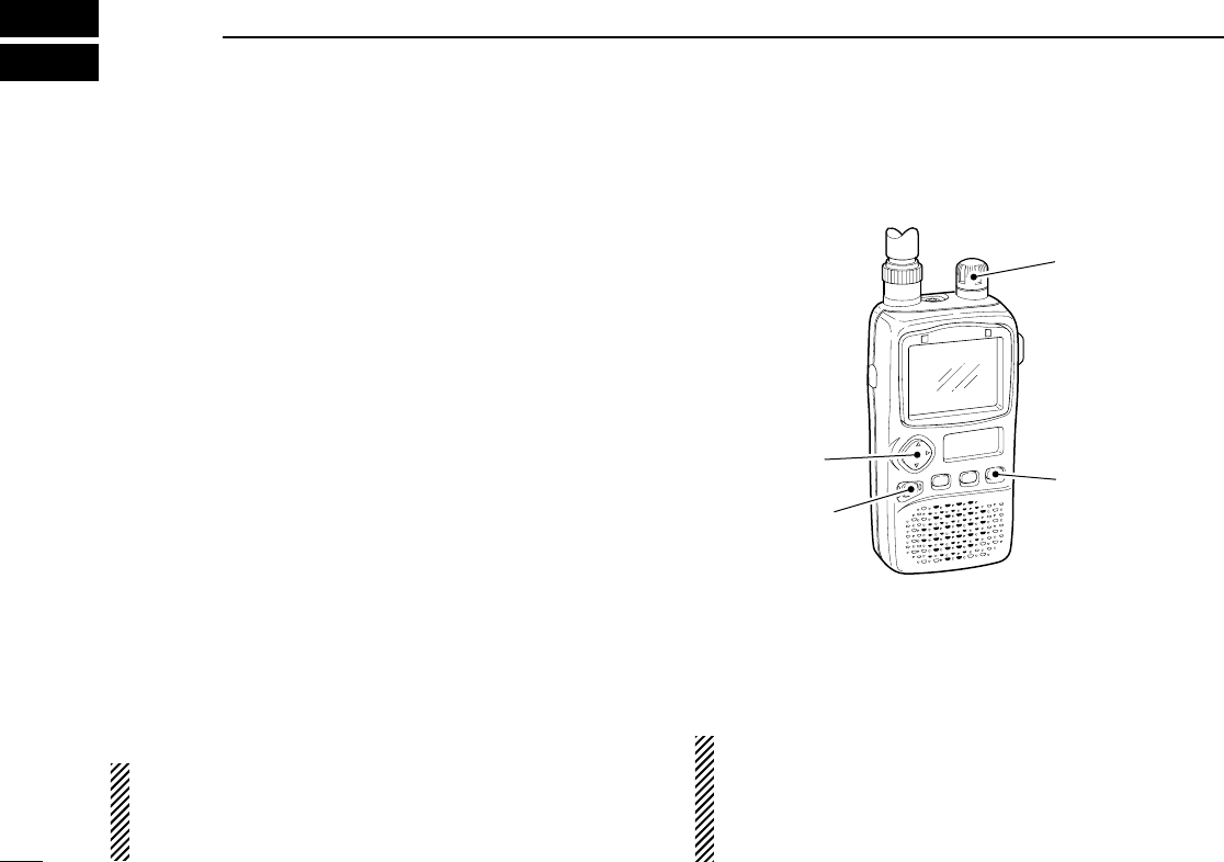
■Panel description
qANTENNA CONNECTOR (p. 1)
Connects the supplied antenna.
wFUNCTION SWITCH [FUNC]
While pushing this switch, other switches and tuning dial
perform secondary functions.
•“Push [FUNC] + a switch”means “while pushing the [FUNC]
switch, push the switch”as indicated by the mark e.g. [↕] etc.
eMULTI FUNCTION SWITCH [MULTI]
➥Push [↕] to adjust the audio level. (p. 11)
➥Push [FUNC] + [↕] to toggle between AM TV (frequency
selection), amateur TV (ATV-type) and WFM/FM/AM
modes when the color LCD is OFF. (p. 34)
➥Push [FUNC] + [↕] for 2 sec. to toggle the color LCD ON
and OFF (p. 6, 30 MHz and above only).
➥Push [FUNC] + [↕] to select color LCD function when the
color LCD is ON. (p. 6)
➥Push [↔] to select the operating band (VHF, UHF, etc.)
in VFO mode. (p. 7)
•Broadcast, HF, 50 MHz, FM broadcast, VHF avionics, 144
MHz, 300 MHz, 400 MHz, 800 MHz, 1200 MHz, 2400 MHz
and TV bands (channel selection) can be selected.
➥Push [FUNC] + [↔] to select the dial select step. (p. 39)
➥Push [↔] for 2 sec. to start a scan. (pgs. 19, 20)
➥Push [FUNC] + [↔] for 2 sec. to start a tone scan. (p.
30)
Push [↕] means push óup or down; and
push [
↔
] means
push óleft or right
.
rPOWER SWITCH [POWER]
Push for 2 sec. to toggle the receiver power ON and OFF.
2
2PANEL DESCRIPTION
q
w
e
r
t
y
u
i
o
Color LCD
(p. 6)
Sub LCD
(p. 4)
SPEAKER
!0
!1

3
2
PANEL DESCRIPTION
tVFO/MEMORY SWITCH [V/M (SKIP)]
➥Push [V/M] to toggle between VFO and memory modes.
(p. 7)
➥Push [V/M] for 1 sec. to enter memory write mode.
➥Push [V/M] for 2 sec. to write the operating frequency
into the selected memory channel in VFO mode. Keep
pushing for 2 sec. or more to automatically select the
next memory channel, if desired. (p. 14)
➥Push [FUNC] + [(V/M)SKIP] to toggle the frequency skip
function ON or OFF in VFO mode. (p. 24)
➥Push [FUNC] + [(V/M)SKIP] to toggle the channel as
skip, program skip or non-skip channel in memory
mode. (p. 22)
➥Push [FUNC] + [(V/M)SKIP] for 2 sec. to program the
memory name while displaying the memory channel in
the color LCD. (p. 17)
yMODE SWITCH [MODE (SET)]
➥Push [MODE] to select the receive mode. (p. 12)
➥Push and hold [MODE] to enter tuning step setting con-
dition and rotate the tuning dial to select the tuning step.
(p. 8)
➥Push [FUNC] + [(MODE)SET] to enter set mode. (p. 38)
➥Push [FUNC] + [(MODE)SET] for 2 sec. to toggle the
lock function ON and OFF. (pgs. 9, 24)
uMONITOR SWITCH [SQL (ATT)]
➥Push and hold to temporarily open the squelch and
monitor the operating frequency. (pgs. 12, 41)
➥While pushing [SQL], rotate the tuning dial to set the
squelch threshold level. (p. 11)
➥Push [FUNC] + [(SQL)ATT] to enter the attenuator set-
ting condition and rotate the tuning dial to set the atten-
uation level. (p. 9)
iEXTERNAL DC POWER JACK [DC 6V]
Allows charging of the BP-206 using the BC-136A/D wall
charger, or using an optional CP-18A/E cigarette lighter cable.
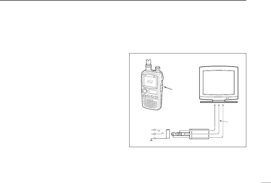
oAUDIO AND VIDEO OUTPUT JACK [A/V OUT]
Outputs a composite video and audio signals. (p. 5)
!0 TUNING DIAL [DIAL]
➥Rotate [DIAL] to set operating frequencies, memory
channels, set mode contents, etc. (pgs. 7, 38)
➥While scanning, changes the scanning direction. (p. 19)
➥While pushing [SQL], sets the squelch level. (p. 11)
➥
While pushing [FUNC], sets the operating frequency in 100
kHz, 1 MHz or 10 MHz steps in VFO mode. (pgs. 8, 39)
➥While pushing [FUNC], sets the memory bank in mem-
ory mode. (p. 16)
➥While pushing [↔], selects programmed scan bank or
memory bank in VFO or memory mode, respectively.
Release [↔] to start the scan. (pgs. 19, 20)
!1 EXTERNAL SPEAKER JACK [SP]
Connects an optional earphone or headphone. The inter-
nal speaker will not function when any external equipment
is connected. (See p. 55 for a list of available options.)
4
2PANEL DESCRIPTION
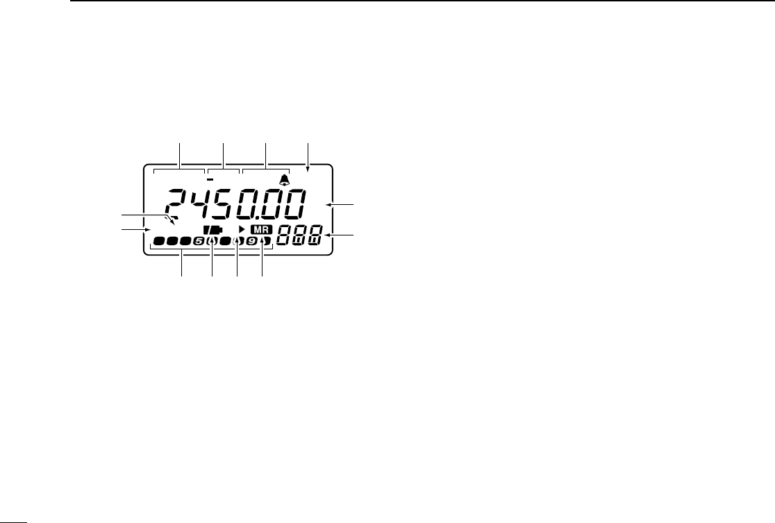
■Function display
qRECEIVE MODE INDICATORS (p. 12)
Show the receive mode.
•AM, FM and WFM are available.
wDUPLEX INDICATORS (p. 31)
Appear when semi-duplex operation (repeater operation)
is in use.
•“–DUP”appears when minus duplex is selected; “DUP”only, ap-
pears when plus duplex is selected.
eTONE INDICATORS (p. 28)
➥“TSQL”appears when the tone squelch function is acti-
vated and “TSQLë”appears during pocket beep oper-
ation.
➥“ë”flashes when the correct tone is received during
pocket beep operation.
rPRIORITY WATCH INDICATOR (p. 25)
Appears when priority watch is in use.
tFREQUENCY READOUT
Shows the operating frequency, set mode contents, etc.
•The smaller “75,”“50”and “25”to the right of the readout indicate
7.5, 5.0 and 2.5 kHz, respectively.
•The decimal point of the frequency flashes during scan.
yMEMORY CHANNEL READOUT (p. 7)
Shows the memory channel number, 8 memory banks
(A–H), etc.
•The 1st digit (A–H) of regular memory indicates memory bank.
•‘tV0’to ‘tV9’indicate AM TV memory channels. (p. 35)
•‘t00’to ‘t49’indicate FM TV memory channels. (p. 36)
•Suffix ‘A’and ‘b’indicate scan edge memory channels.
uMEMORY MODE INDICATOR (p. 7)
Appears when a memory channel is selected.
AM FM DUP
W
P
ATTRX
PRIO
75
50
25
TSQL
qwe
u
r
y
t
!0 o
!1
!2
i
5
2
PANEL DESCRIPTION
iSKIP SCAN INDICATOR (pgs. 22, 24)
➥“"”appears when the selected memory channel is set
as a skip channel in memory mode.
➥“P"”shows that the skip frequency function is turned
ON or OFF in VFO mode.
➥“P"”appears when the selected memory channel is set
to be skipped during VFO scan (full, band and pro-
grammed scan) in memory mode.
oBATTERY INDICATORS
➥Both segments appear when the batteries have enough
capacity.
➥Only the right segment appears when the batteries are
nearing exhaustion.
•“Low V”appears when battery replacement is necessary and
the color LCD is ON.
•The U.S.A. version automatically turns itself OFF when the re-
ceiver detects that battery replacement is necessary.
!0 S (SIGNAL) INDICATORS
Show the relative signal strength while receiving.
!1 BUSY INDICATOR
“RX”appears when receiving a signal or when the squelch
is open.
!2 ATTENUATOR INDICATOR (p. 9)
Appears when the attenuator function is in use.
•Audio and video output jack information
•Video output impedance : 75 Ω, 1 Vp-p typical
•Audio output impedance : 1 kΩ, 300 mVrms typical
Audio
Audio
[A/V OUT]
3-conductor
3.5 (d) mm (1⁄8˝)
connector
Video
Video
Television
Ground
Ground
To [A/V OUT]
6
2PANEL DESCRIPTION
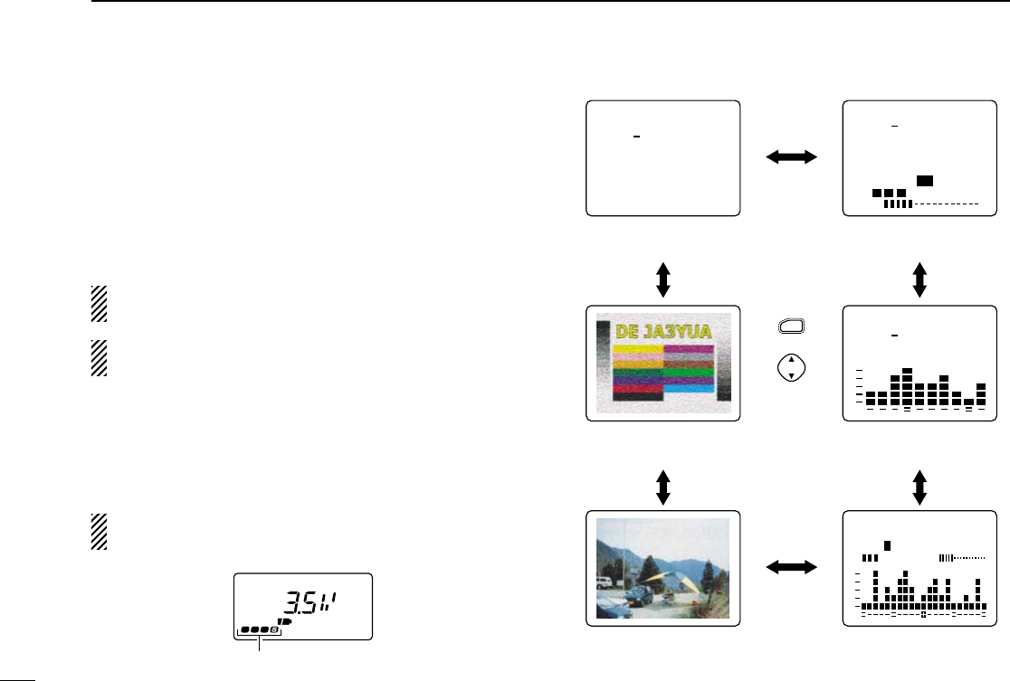
■Dual LCD
The receiver has dual LCDs for versatile display selection.
The color LCD has 5 screens and 1 optional screen as fol-
lows:
simple, multi-function, band scope, direction finding, TV (fre-
quency selection) and amateur TV* screen.
*Amateur TV screen can be selected for the ATV-type and
1200/2400 MHz bands only.
The color LCD can be used when the operating frequency
is 30 MHz and above.
qPush [FUNC] + [↕] for 2 sec. to turn the color LCD ON, if
desired.
wPush [FUNC] + [↕] momentarily one or more times to tog-
gle the screen of the color LCD.
While the color LCD is in use, the sub LCD displays the
voltage of the power source.
RX
Appears when simple screen is selected.
VOL
RX
FM PSKIP
146.100.000
TS 15.0
S1 3 5 7 9
FM PSKIP
146.100.000
15.0 TS
FM PSKIP
146.100.000
15.0
TS
FM PSKIP
146.100.000 TS= 15.0
SWEEP- 10KS1 3 5 7 9
RX VOL
FUNC
+
momentarily
Direction finding
screen (p. 37)
Simple screen
ATV screen (p. 36;
ATV type, 1200/2400 MHz bands only
)
TV screen (p. 34;
frequency selection)
Multi-function
screen
Band scope
screen (p. 33)
7
3
FREQUENCY AND CHANNEL SETTING
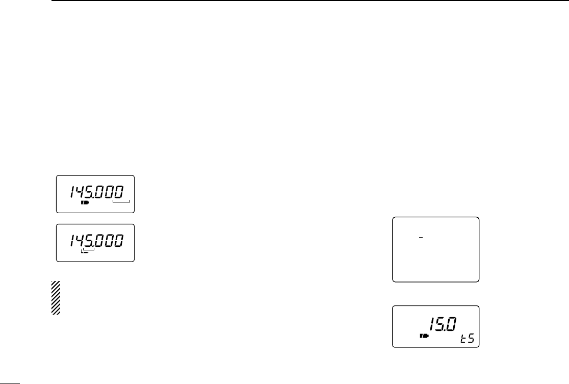
■VFO and memory channels
This receiver has 2 normal operating modes: VFO mode and
memory mode.
VFO mode is used for setting a de-
sired frequency within the fre-
quency coverage.
➥Push [V/M] to select VFO mode.
Memory mode is used for opera-
tion of memory channels which
have programmed frequencies.
➥Push [V/M] to select memory
mode.
•“X”or “M:”appears when a mem-
ory channel is selected.
•To program a memory, refer to p. 14.
•TV band and ATV (ATV type) have
separate memory channels (pgs.
35, 36)
What is VFO?
VFO is an abbreviation of Variable Frequency Oscillator. Fre-
quencies for receiving are generated and controlled by the
VFO.
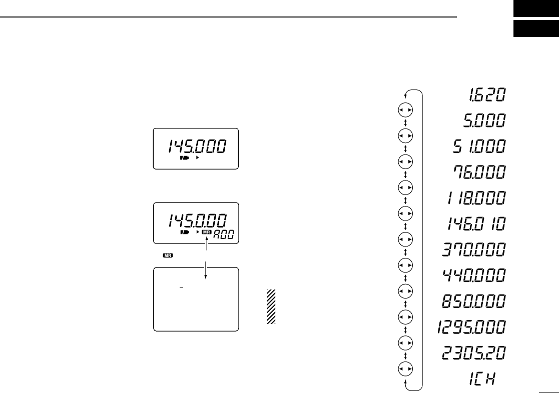
■Operating band selection
The receiver can receive the
broadcast band, HF band, 50
MHz band, FM broadcast
band, VHF avionics band, 144
MHz band, 300 MHz band,
400 MHz band, 800 MHz
band,* 1200 MHz, 2400 MHz
or TV band.
*Some frequencies cannot be re-
ceived with the U.S.A. version.
➥Push [↔] several times to
select the desired band.
•When a memory channel is
selected, the first push of [↔]
selects VFO mode.
Amateur TV screen is also
selected for the ATV-type
IC-R3. (p. 36)
FM
P
FM
P
FM PSKIP
145.000.000
15.0 TS
M:A00
“ ” or “M:” appears.
0.495–1.620 MHz
1.625–29.995 MHz
30.0–75.995 MHz
76.0–107.995 MHz
136.0–255.095 MHz
108.0–135.995 MHz
255.1–382.095 MHz
382.1–769.795 MHz
769.8–960.095 MHz
960.1–1399.995 MHz
1400.0–2450.095 MHz
TV band (CH selection)
8
3FREQUENCY AND CHANNEL SETTING
■Setting a frequency
qSelect the desired band with [↔].
wRotate [DIAL] to change the frequency.
•The frequency changes according to the preset tuning steps. See
the right section for selecting the tuning step.
•Some TV channels may be set as skip channels by default and
can be selected by rotating [DIAL] while pushing [FUNC]. (p. 34).
•Push [↔] while pushing [FUNC] to change the frequency in 100
kHz, 1 MHz or 10 MHz steps.
The 1 MHz tuning step (dial select step) can be set to 100
kHz, 1 MHz or 10 MHz tuning steps in set mode. See p. 39
for details.
■Setting a tuning step
Tuning steps can be selected for each band, however, the tun-
ing step of the broadcast band is fixed to 9 kHz steps except
for U.S.A. and Canada versions. The following are available.
•5 kHz •6.25 kHz* •10 kHz •12.5 kHz •15 kHz
•20 kHz •25 kHz •30 kHz •50 kHz •100 kHz
*Not available for 1200 MHz band.
qSelect the desired band, except for TV band, with [↔].
wRotate [DIAL] while pushing [MODE] to select the desired
tuning step.
FM
146.100.000
15.0 TS
•15 kHz tuning step (Simple screen)
•15 kHz tuning step (Sub LCD)
FM
75
50
25
FM
75
50
25
[DIAL] changes the frequency according
to the selected tuning step.
While pushing [FUNC], [DIAL] changes
the frequency in 1 MHz steps (default).
9
3
FREQUENCY AND CHANNEL SETTING
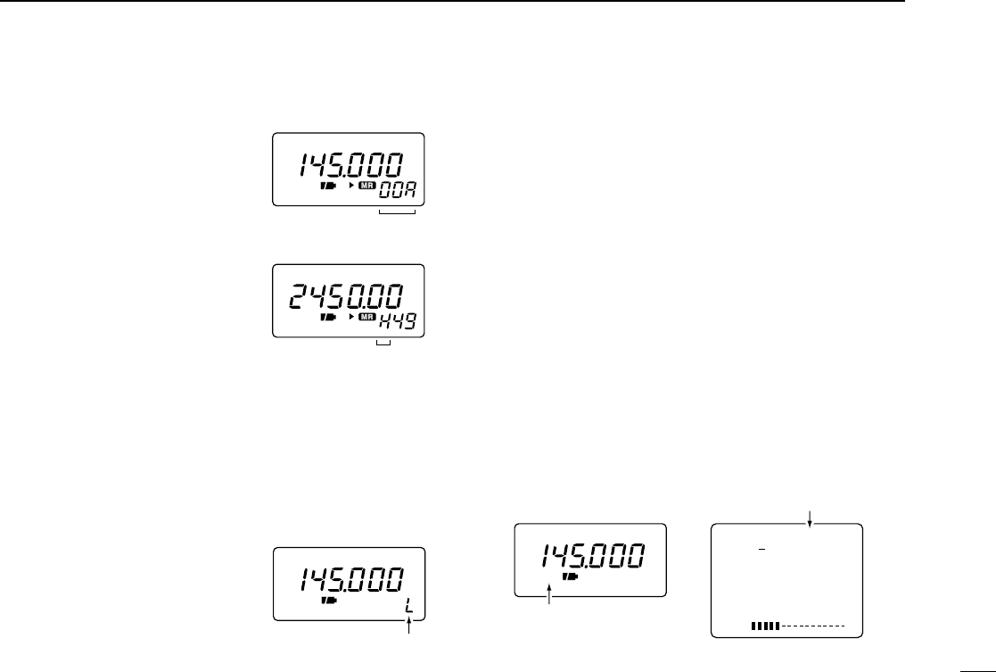
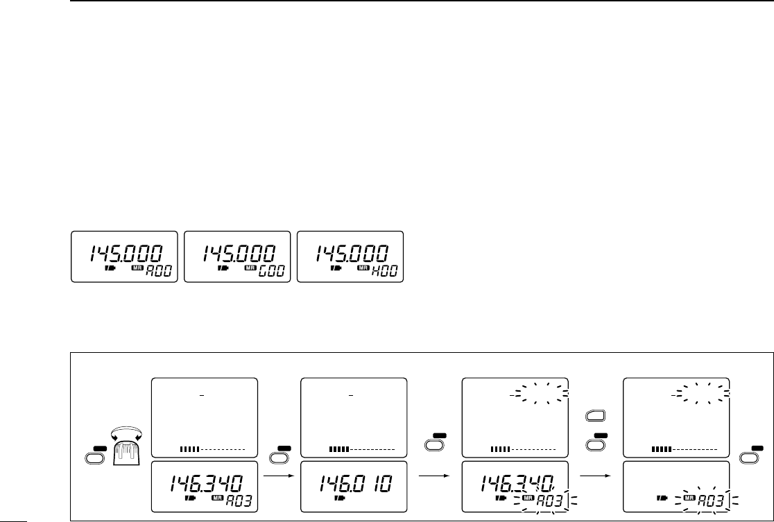
■Selecting a memory channel
qPush [V/M] to select memory
mode.
•“X”or “M:”appears when a mem-
ory channel is selected.
wRotate [DIAL] to change the indi-
cated memory channel.
•Only programmed memory chan-
nels can be selected.
•Rotate [DIAL] while pushing [FUNC]
to change the memory bank.
■Lock function
The lock function prevents accidental frequency changes and
accidental function access.
➥Push [FUNC] + [MODE] for 2 sec. to toggle the lock func-
tion ON and OFF.
•[POWER], [↕(VOL)] and [SQL] can
still be accessed while the lock func-
tion is ON (default).
•Accessible switches can be set to 1
of 4 groups in set mode. See p. 42
for details.
■Attenuator function
The attenuator prevents a desired signal from distorting when
very strong signals are near the desired frequency or when
very strong electric fields, such as from a broadcasting sta-
tion, are near your location.
The receiver has 4 attenuation levels for various operating
conditions. The attenuator functions when the operating fre-
quency is 1149.995 MHz or below.
qPush [FUNC] + [(SQL)ATT] to enter the attenuator setting
condition.
wRotate [DIAL] to set the attenuation level 1–4 or turn the
attenuator function OFF.
•“ATT1”– “ATT4”appears in the color LCD when the color LCD is
ON; “ATT”appears in the sub display when the color LCD is OFF.
ePush [(SQL)ATT] to exit the attenuator setting condition.
FM
ATT
S1 3 5 7 9
VOL
FM ATT4
145.000.000
TS 15.0
Shows when the attenuator
is in use.
Shows when the attenuator
(level 4) is in use.
FM
P
FM
P
[DIAL] changes the
memory channel.
While pushing [FUNC],
[DIAL] changes the
memory bank.
FM
“ L ” appears when the
lock function is in use.
10
4BASIC OPERATION
■Receiving
Make sure a charged battery pack or alkaline batteries are in-
stalled. (pgs. 1, 46)
qPush [POWER] for 2 sec. to turn power ON.
wPush [↕] to set the desired audio level.
•One of the LCDs shows the volume level while setting. See the
next page for details.
ePush [↔] to select an operating band. (p. 7)
rRotate [DIAL] to set an operating frequency. (p. 8)
tSet the squelch level.
•While pushing [SQL], rotate [DIAL].
•The first click of [DIAL] indicates the current squelch level.
•“LEVEL1”is loose squelch and “LEVEL9”is tight squelch.
•“AUTO”indicates automatic level adjustment with a noise pulse
count system.
•Push and hold [SQL] to open the squelch manually. (default be-
haviour; p. 41)
yWhen a signal is received:
➥Squelch opens and audio is emitted from the speaker.
➥The S indicators show the relative signal strength.
➥The busy indicator appears when receiving a signal or when the
squelch is open.
q Power switch
w Set volume
e Select band t Push for setting
the squelch
(Push to monitor)
r Set frequency
t Set the squelch
level
For non-U.S.A. versions
If the display mode selection is set as ‘manual’(p. 43) with
the color LCD ON, the receiver may not be able to turn it-
self OFF when the battery becomes exhausted.
Replace the battery and turn power OFF in this case.
For U.S.A. version
The U.S.A. version automatically turns itself OFF when the
receiver detects that battery replacement is necessary. Re-
place the battery or charge the battery pack in this case.
11
4
BASIC OPERATION
■Setting volume level
The audio level can be adjusted through 32 levels.
➥Push [↕] to set the desired audio level.
•Beep tone sounds while setting. This indicates the approximate
sound level. (default behaviour; p. 40)
•Pushing and holding these keys changes the audio level contin-
uously.
•One of the LCDs shows the volume level while setting.
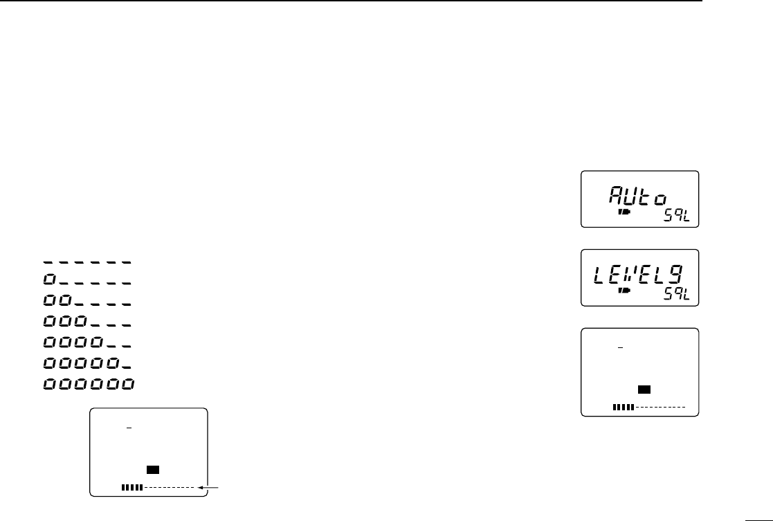
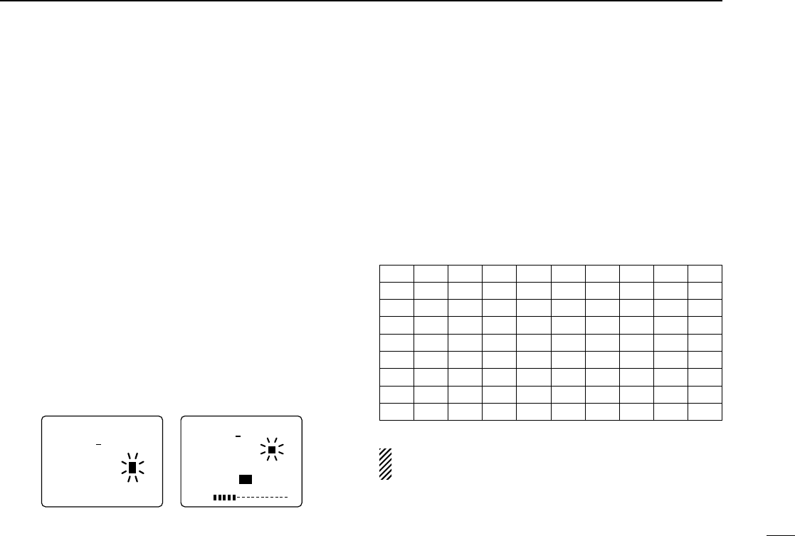
■Setting squelch level
The squelch circuit mutes the received audio signal depend-
ing on the signal strength. The receiver has 9 squelch levels,
a continuously open setting and an automatic squelch setting.
➥While pushing [SQL], rotate the
[DIAL] to select the squelch level.
•The first click of [DIAL] indicates the
current squelch level.
•“LEVEL1”is loose squelch and
“LEVEL9”is tight squelch.
•“AUTO”indicates automatic level
adjustment with a noise pulse count
system.
•“OPEN”indicates continuously open
setting.
S1 3 5 7 9
VOL
FM
146.100.000
TS 15.0
AUDIO LEVEL
INDICATION
(Sub LCD)
Min. setting (no audio)
:
Initial setting
:
:
:
Max. setting
Volume level
S1 3 5 7 9
VOL
FM
146.100.000
TS 15.0
Automatic squelch
Maximum level
level 5
12
4BASIC OPERATION
■Monitor function
This function is used to listen to weak signals or to open the
tone squelch manually.
➥Push and hold [SQL] to monitor the operating frequency.
•“RX”flashes while monitoring.
The [SQL] switch can be set to ‘sticky’operation in set
mode. (p. 41)
You can monitor duplex communication by pushing the
[SQL] switch when the duplex function is in use. (p. 31)
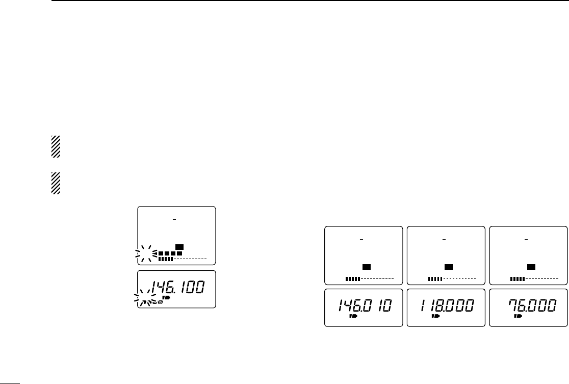
■Receive mode selection
Receive modes are determined by the physical properties of
the radio signals.The receiver has 3 receive modes: FM, AM
and WFM modes. TV and ATV (ATV type only) also use WFM
mode. The mode selection is stored independently in each
band and memory channels.
Typically, AM mode is used for the AM broadcast stations
(0.495–1.620 MHz) and air band (118–135.995 MHz), and
WFM is used for FM broadcast stations (76–107.9 MHz).
➥Push [MODE] one or more times to select the desired re-
ceive mode.
S1 3 5 7 9
VOL
FM
146.010.000
TS 15.0
S1 3 5 7 9
VOL
AM
118.000.000
TS 25.0
S1 3 5 7 9
VOL
WFM
76.000.000
TS 50.0
FM AM FM
W
AM mode WFM modeFM mode
S1 3 5 7 9
VOL
RX
FM
146.100.000
TS 15.0
FM
RX
13
4
BASIC OPERATION
TV screens cannot be selected by pushing [MODE]. See p.
34 for TV operation details.
■Display backlighting
The receiver has display backlighting with a 5 sec. timer for
nighttime operation. The display backlighting can be turned
ON continuously or turned OFF, if desired.
➥Push any switch except [FUNC]; or, rotate [DIAL] to turn the
backlighting ON.
•When auto backlighting is set, the backlighting will automatically
turn OFF when switches and [DIAL] have not been operated for 5
sec.
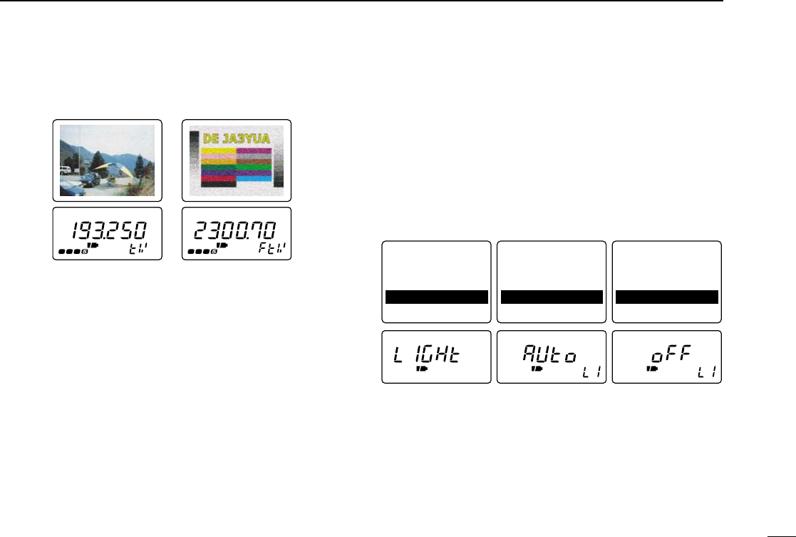
◊Setting the backlighting condition
qPush [FUNC] + [(MODE)SET] momentarily to enter set
mode.
•Select a non-band scope screen in advance for color LCD.
wRotate [DIAL] until “LIGHT”appears.
•“LIGHt”disappears after 1 sec. and the previously selected back-
lighting timer and “LI”appears when color LCD is OFF.
ePush [↔] or rotate the tuning dial while pushing [FUNC] to
select the desired backlighting condition.
rPush [(MODE)SET] to exit set mode.
Pause Scan : 10SEC
Priority : OFF
Beep Audio : VOLUME
Light : AUTO
A.Power OFF : OFF
Pause Scan : 10SEC
Priority : OFF
Beep Audio : VOLUME
Light : AUTO
A.Power OFF : OFF
Pause Scan : 10SEC
Priority : OFF
Beep Audio : VOLUME
Light : OFF
A.Power OFF : OFF
Automatic backlighting
Backlighting set
mode Continuously OFF
FM
W
FM
W
RX RX
FM TV mode
(ATV type only)
TV screen
frequency selection
■General
The receiver has 400 memory channels in 8 banks (A–H) for
storage of often-used frequencies.
◊Memory channel contents
The following information can be programmed into memory
channels:
•Operating frequency (p. 8)
•Receive mode (p. 12)
•Tuning step (p. 8)
•Memory name (p. 17)
•Duplex direction (DUP or –DUP) with an offset frequency
(p. 31)
•Tone squelch ON/OFF (p. 28)
•Tone squelch frequency (p. 28)
•Scan skip setting (p. 22)
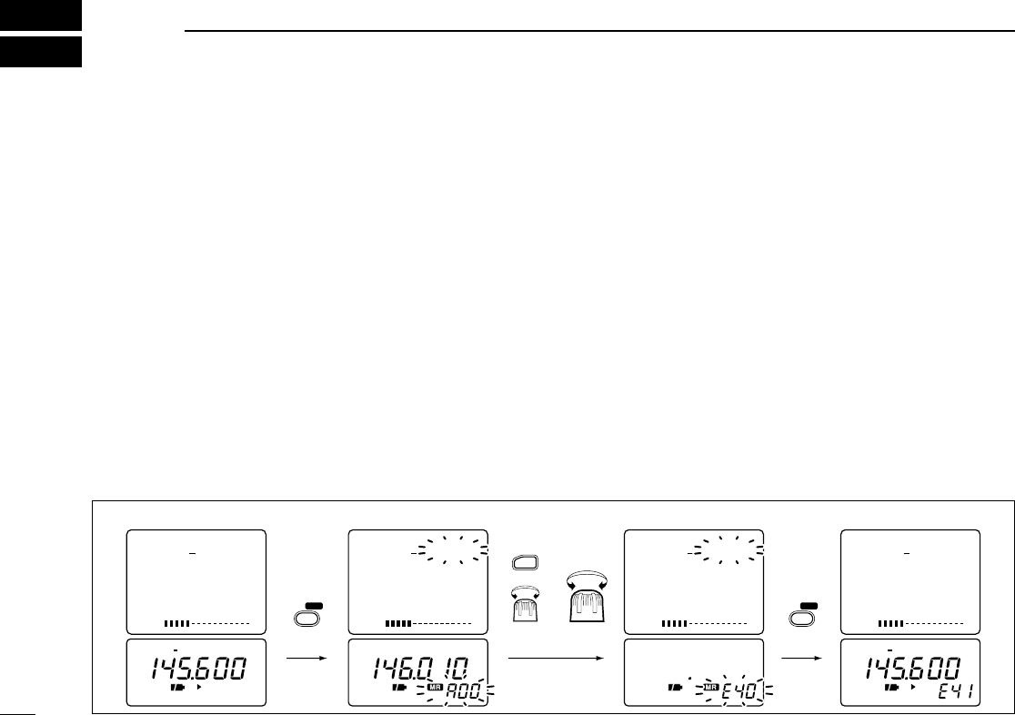
■
Programming during selection
qPush [↔] to select an operating band.
wSet the desired frequency:
➥Set the frequency using [DIAL].
➥Set other data (e.g. offset frequency, duplex direction,
tone squelch frequency, etc.), if required.
ePush [V/M] for 1 sec. to indicate memory channels.
•Do not hold [V/M] for more than 2 sec., otherwise the previously
selected memory channel will be overwritten.
rRotate [DIAL] to select the desired channel.
•VFO (VF), as well as regular memory channels, can be pro-
grammed in this way.
•Rotate [DIAL] while pushing [FUNC] to select a memory bank
(A–H), programmed scan edge channel or VFO (VF).
tPush [V/M] for 1 sec. to program.
•Keep pushing for 2 sec. or more to automatically select the next
memory channel, if desired.
14
5MEMORY CHANNELS
FM DUPTSQL
P
FM
V/M SKIP V/M SKIP
FUNC
FM DUPTSQL
P
S1 3 5 7 9
VOL
FM PSKIPTSQL–DUP
145.600.000
TS 15.0
S1 3 5 7 9
VOL
FM
146.010.000
M:A00
TS 15.0
S1 3 5 7 9
VOL
. .
M:E40
TS .
S1 3 5 7 9
VOL
FM PSKIPTSQL–DUP
145.600.000
E41
TS 15.0
for 1 sec.
blank
channel
for 2 sec.
for bank
selection for CH
selection
+
[EXAMPLE]: Programming ch 40 of memory bank E during selection (and ch 41 selection).
■Programming after selection
qSelect memory mode with [V/M].
wSet the memory channel to be programmed with [DIAL].
•Rotate [DIAL] while pushing [FUNC] to select a memory bank
(A–H) or programmed scan edge channel.
•Non-programmed channels cannot be selected.
ePush [V/M] to select VFO mode.
rSet the desired frequency:
➥Select the desired band with [↔].
➥Set the frequency using [DIAL].
➥Set other data (e.g. offset frequency, duplex direction,
tone squelch frequency, etc.), if required.
tPush [V/M] for 2 sec. to program the selected channel.
•Keep pushing for 2 sec. or more to automatically select the next
memory channel, if desired.
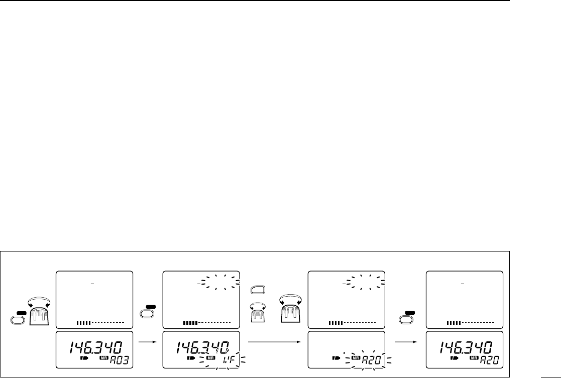
■Transferring memory
contents to another memory
qSelect memory mode with [V/M].
wSelect the memory channel to transfer with [DIAL].
•Rotate [DIAL] while pushing [FUNC] to select a memory bank
(A–H) or programmed scan edge channel.
ePush [V/M] for 1 sec. to indicate memory channels.
•Do not hold [V/M] for more than 2 sec., otherwise the memory
channel contents will be transferred to VFO.
rRotate [DIAL] to select the channel to transfer to.
•Rotate [DIAL] while pushing [FUNC] to select a memory bank or
programmed scan edge channel.
•VFO (VF), as well as regular memory channels, can be trans-
ferred in this way.
tPush [V/M] for 2 sec. to transfer.
15
5
MEMORY CHANNELS
FM FM
S1 3 5 7 9
VOL
FM
146.340.000
M:A03
TS 15.0
S1 3 5 7 9
VOL
FM
146.340.000
M: VF
TS 15.0
FM
FUNC
S1 3 5 7 9
VOL
. .
M:A20
TS .
S1 3 5 7 9
VOL
FM
146.340.000
M:A20
TS 15.0
for
1 sec.
Select memory
channel for 2 sec.
blank
channel
V/M SKIP
V/M SKIP
V/M SKIP
for bank
selection for CH
selection
+
[EXAMPLE]: Transferring memory channel 3 (memory bank A) to 20 (memory bank A).
■Memory bank selection
The receiver has 400 memory channels in 8 banks (A–H) for
storage of often-used frequencies.
qSelect memory mode with [V/M].
wRotate [DIAL] while pushing [FUNC] to select the desired
memory banks.
eRotate [DIAL] to select the desired memory channel.
■Memory clear
Unwanted memory channels can be cleared (erased). Before
clearing a memory channel, make sure it is no longer needed
as cleared memories cannot be recalled.
qSelect memory mode with [V/M].
wSet the memory channel to be cleared with [DIAL].
•Rotate [DIAL] while pushing [FUNC] to select a memory bank
(A–H) or programmed scan edge channel.
eSelect VFO mode with [V/M] and push [V/M] for 1 sec. to
indicate the selected memory channel.
•Do not hold [V/M] for more than 2 sec., otherwise the selected
memory channel will be overwritten.
rPush [FUNC] + [V/M] for 2 sec. to clear.
•3 beeps sound, then the frequency is cleared.
tPush [MODE] to return to VFO mode.
FM FM FM
Memory bank A Memory bank G Memory bank H
16
5MEMORY CHANNELS
FM FM FM
S1 3 5 7 9
VOL
FM
146.340.000
M:A03
TS 15.0
S1 3 5 7 9
VOL
FM
146.010.000
TS 15.0
S1 3 5 7 9
VOL
FM
146.340.000
M:A03
TS 15.0
S1 3 5 7 9
VOL
. .
M:A03
TS .
MODE SET
Select memory
channel
for 2 sec.
+
for 1 sec.
V/M SKIP
V/M SKIP
V/M SKIP
V/M SKIP
FUNC
[EXAMPLE]: Clearing memory channel 3 (memory bank A).
17
5
MEMORY CHANNELS
■Memory names
Each memory channel and scan edge channels can be pro-
grammed with an alphanumeric name such as a repeater
name, club name, etc., for easy recognition. Names can be a
maximum of 6 characters—see the table at right for available
characters.
The color LCD and memory names can be used when the
operating frequency is 30 MHz and above.
qPush [FUNC] + [↕] for 2 sec. to turn the color LCD ON.
wPush [FUNC] + [↕] one or more times to select the simple
or multi-function screen.
•The memory names are available for the simple and multi-func-
tion screens only.
eSelect the desired memory channel.
rPush [FUNC] + [(V/M)SKIP] for 2 sec. to program the
memory name.
•The first character of the name flashes.
tRotate the tuning dial to select the desired character.
•See the following table for a list of available characters.
yPush [↔] (right) to advance to the next character.
•Push [↔] (left) to select the previous character.
uRepeat tand yuntil the desired name is input.
iPush [V/M] to program the name and exit programming
mode.
oIf you want to set other channels, rotate the tuning dial. Re-
peat rthrough ito set the desired name.
The memory names are automatically programmed into
the memory channels.
S1 3 5 7 9
VOL
FM FM
M:A00
146.100.000
15.0
JA3
TS
146.100.000
M:A00
TS 15.0
JA3
ABCDEF GHI J
KLMNOPQRS T
UVWX YZ a bc d
ef ghi j kl mn
opqr st uvwx
yz01234567
89?! $%#+–M
/=():;.,_’
~space
18
6SCAN OPERATION
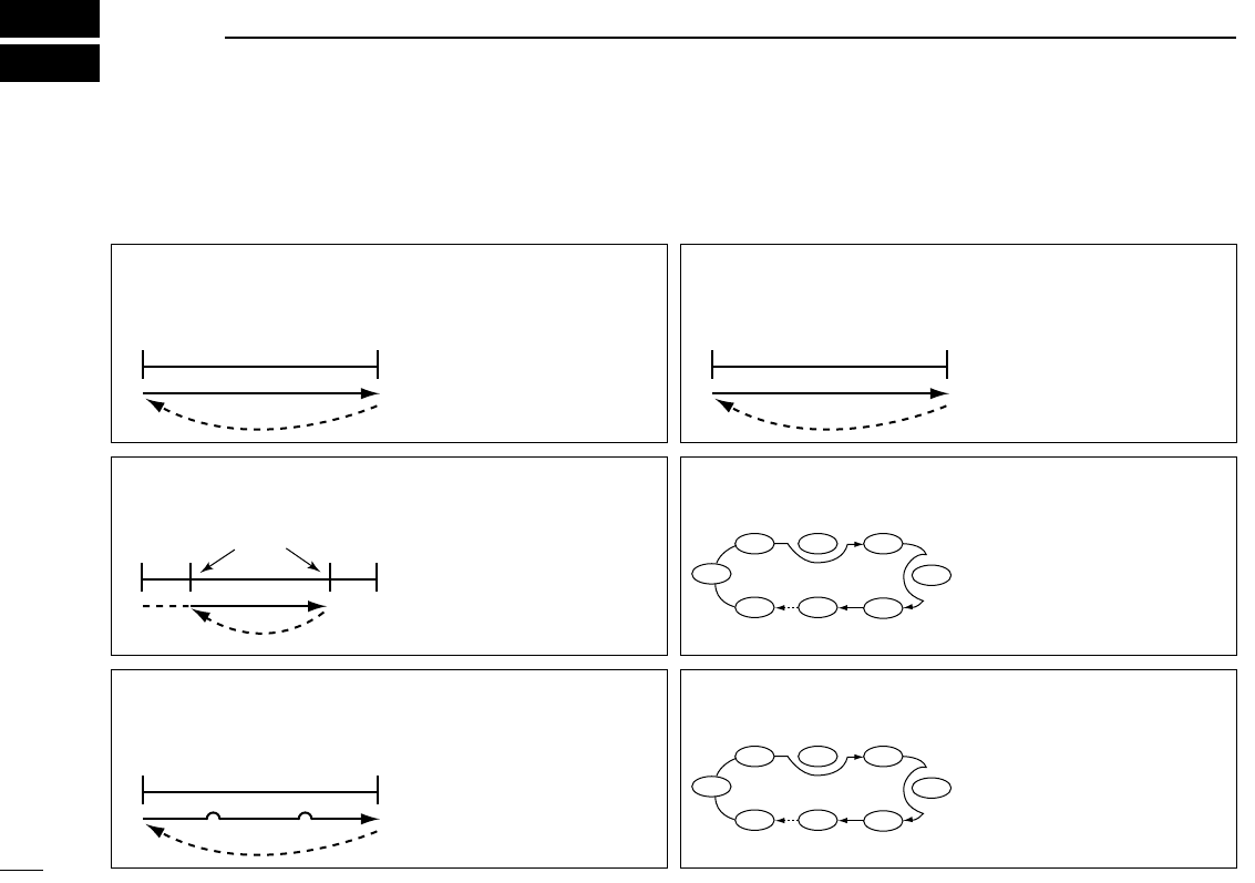
■Scan types Up to 25 programmed scan ranges (00A/00b to 24A/24b), full
scan, band scan and memory bank scan provide scanning
versatility. Each scan can have skip channels programmed.
FULL SCAN (p. 19) Repeatedly scans all fre-
quencies over the entire re-
ceiver range.
U.S.A. version cannot re-
ceive some frequencies.
PROGRAMMED SCAN
(p. 19)
Repeatedly scans between
two user-programmed fre-
quencies. Used for checking
for frequencies within a
specified range such as re-
peater output frequencies,
etc.
495
kHz 2450.095
MHz
Scan
Jump
SELECTED BAND SCAN
(p. 19) Repeatedly scans all fre-
quencies over the entire se-
lected band.
Scan
Jump
Scan
Jump
Scan edges
MEMORY SKIP FUNCTION
(p. 22) Skips unwanted memory
channels that inconvenient-
ly stop scanning. Skip
channels can be toggled
ON and OFF by pushing
[FUNC] + [(V/M) SKIP] in
memory mode.
Not yet
programmed
ch 00
ch 01 ch 02 ch 03
ch 04
ch 05
ch 06ch 49
Band edge or
scan edge
Band edge or
scan edge
FREQUENCY SKIP
FUNCTION (p. 24) Skips unwanted frequen-
cies that inconveniently
stop scanning. This func-
tion can be turned ON and
OFF in frequency skip func-
tion set mode.
MEMORY (BANK) SCAN
(p. 20) Repeatedly scans memory
channels except skip chan-
nels within all programmed
channels or within a mem-
ory bank (A–H).
Not yet
programmed
SKIP
ch 00
ch 01 ch 02 ch 03
ch 04
ch 05
ch 06ch 49
Band
edge
Band
edge
Band
edge
Band
edge
Jump
Skip Skip
Scan
19
6
SCAN OPERATION
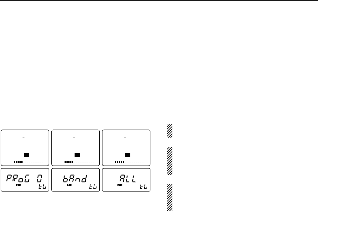
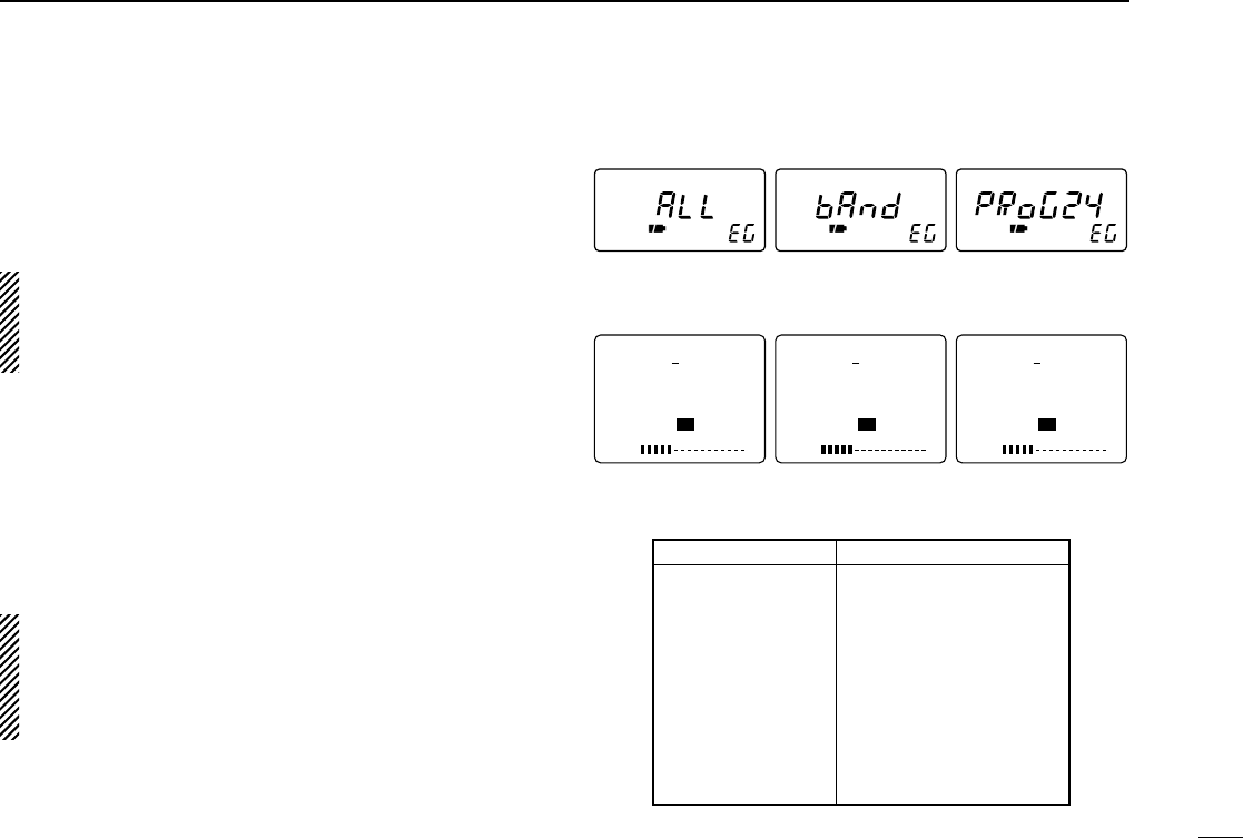
■Full/band/programmed scan
Scanning searches for signals automatically and makes it
easier to locate new stations for listening purposes, etc.
qSelect VFO mode with [V/M].
wMake sure the squelch is set to the threshold point.
•Select automatic squelch (AUTO) or a level (1–9) where the
noise is just muted. (p. 10)
ePush and hold [↔], then rotate [DIAL] to select desired
scan edge.
•“ALL”for full scan, “BAND”for band scan or “PROG(RAM) 0”–
“PROG(RAM)24”for programmed scan. (see the next page)
rRelease [↔] to start the scan.
•Decimal point(s) flashes while scanning.
•“PSKIP”appears when the frequency skip function is turned ON.
(p. 19)
•“0P”–“24P”flash to indicate which pair of scan edges is being
scanned.
•To change the scanning direction, rotate [DIAL].
•If the pocket beep function is activated, the receiver automatically
selects the tone squelch function when a scan starts.
tTo stop the scan, push [↔] again.
If the same frequencies are programmed into a pair of
scan edges, programmed scan does not start.
For programmed scan, scan edges must be programmed
in advance. Program scan edges in the same manner of
programming a memory channel (p. 14) and select a scan
edge. (p. 21)
A tone scan function is available to search for subaudible
tones (e.g. when you want to find a subaudible tone fre-
quency necessary to open a repeater or to open the tone
squelch). See p. 30 for details.
S1 3 5 7 9
VOL
FM PSKIP
146.100.000
TS 15.0
PROGRAM 0
S1 3 5 7 9
VOL
FM PSKIP
146.100.000
TS 15.0
BAND
S1 3 5 7 9
VOL
FM PSKIP
146.100.000
TS 15.0
ALL
Band scanProgrammed scan 0 Full scan
20
6SCAN OPERATION
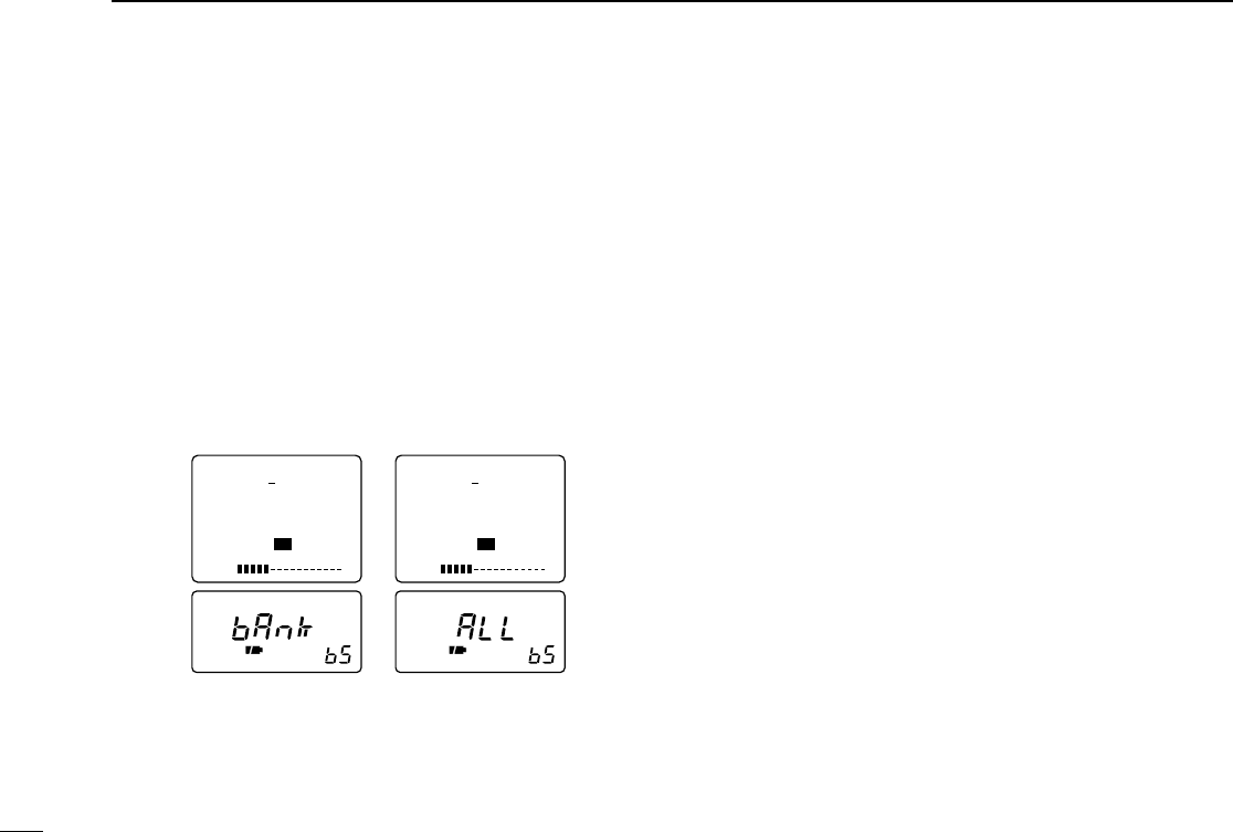
■Memory (bank) scan
qSelect memory mode with [V/M].
wFor memory bank scan, rotate [DIAL] while pushing
[FUNC] to select the desired memory bank.
eMake sure the squelch is set to the threshold point.
•Select automatic squelch (AUTO) or a level (1–9) where the
noise is just muted. (p. 11)
rPush and hold [↔], then rotate [DIAL] to turn the memory
bank scan ON or OFF.
•“ALL”indicates all memory banks are scanned (memory bank
scan OFF); “BANK”indicates the selected memory bank is
scanned (memory bank scan ON).
tRelease [↔] to start the scan.
•Decimal point(s) flashes while scanning.
•To change the scanning direction, rotate [DIAL].
•If the pocket beep function is activated, the receiver automatically
selects the tone squelch function when a scan starts.
yTo stop the scan, push [↔] again.
S1 3 5 7 9
VOL
FM PSKIP
146.100.000
TS 15.0
BANK
M:A00
S1 3 5 7 9
VOL
FM PSKIP
146.100.000
TS 15.0
ALL
M:A00
Bank scan OFFBank scan ON
21
6
SCAN OPERATION
■Selecting scan edges
The scanning range can be set to all frequencies (full scan), a
selected band (band scan) or between two user-programmed
frequencies (programmed scan).
The programmed scan edges can be programmed in the
same manner as programming regular memory channels.
Program the desired scan edge frequencies in a pair of
programmed scan edge channels in advance. (pgs. 14, 15)
qSelect VFO mode with [V/M].
wPush and hold [↔], then rotate [DIAL] to select desired
scan edge.
•“ALL”for full scan, “BAND”for band scan or “PROG(RAM) 0”–
“PROG(RAM)24”for programmed scan.
eRelease [↔] to start the programmed scan using the se-
lected edges.
When scanning across the band as follows (programmed
scan edges are set across the band), the parameters like
tuning step, receive mode, offset frequency, duplex direc-
tion, etc. are used in each bands’VFO settings instead of
these scan edges.
•Band ranges
FREQUENCY RANGE
BAND
Broadcast band
HF band
50 MHz band
FM broadcast band
VHF avionics band
144 MHz band
300 MHz band
400 MHz band
800 MHz band
1200 MHz band
2400 MHz band
0.495 – 1.620 MHz
1.625 – 29.995 MHz
30.0 – 75.995 MHz
76.0 – 107.995 MHz
108.0 – 135.995 MHz
136.0 – 255.095 MHz
255.1 – 382.095 MHz
382.1 – 769.795 MHz
769.8 – 960.095 MHz
960.1 – 1399.995 MHz
1400.0 – 2450.095 MHz
S1 3 5 7 9
VOL
FM
146.100.000
TS 15.0
ALL
S1 3 5 7 9
VOL
FM
146.100.000
TS 15.0
PROGRAM24
S1 3 5 7 9
VOL
FM
146.100.000
TS 15.0
BAND
Full scan Band scan Programmed scan 24
(Scan edge channels
24A and 24b)
22
6SCAN OPERATION
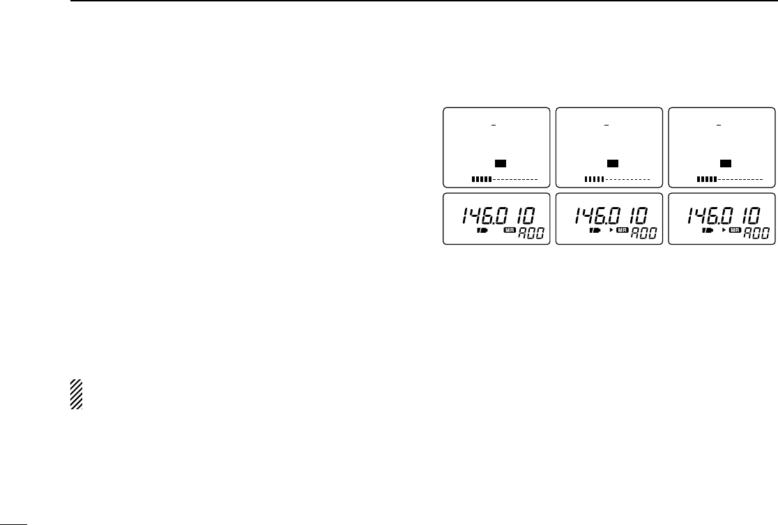
■Skip channel setting
Memory channels can be set to be skipped for memory skip
scan. In addition, memory channels can be set to be skipped
for both memory skip scan and frequency skip scan. These
are useful to speedup the scan interval.
qSelect memory mode with [V/M].
wRotate [DIAL] to select a memory channel to be pro-
grammed as a skip channel.
eWhile pushing [FUNC], push [(V/M)SKIP] one or more
times to select a condition.
•No indication : channel will not be skipped.
•“SKIP”or “"”appears : channel skipped during memory
scan.
•“PSKIP”or “P"”appears: channel skipped during memory
scan; frequency skipped during full,
band and programmed scans.
This setting is effective when the frequency skip function
(“PSKIP”or “P"”) is turned ON. See p. 24 for details.
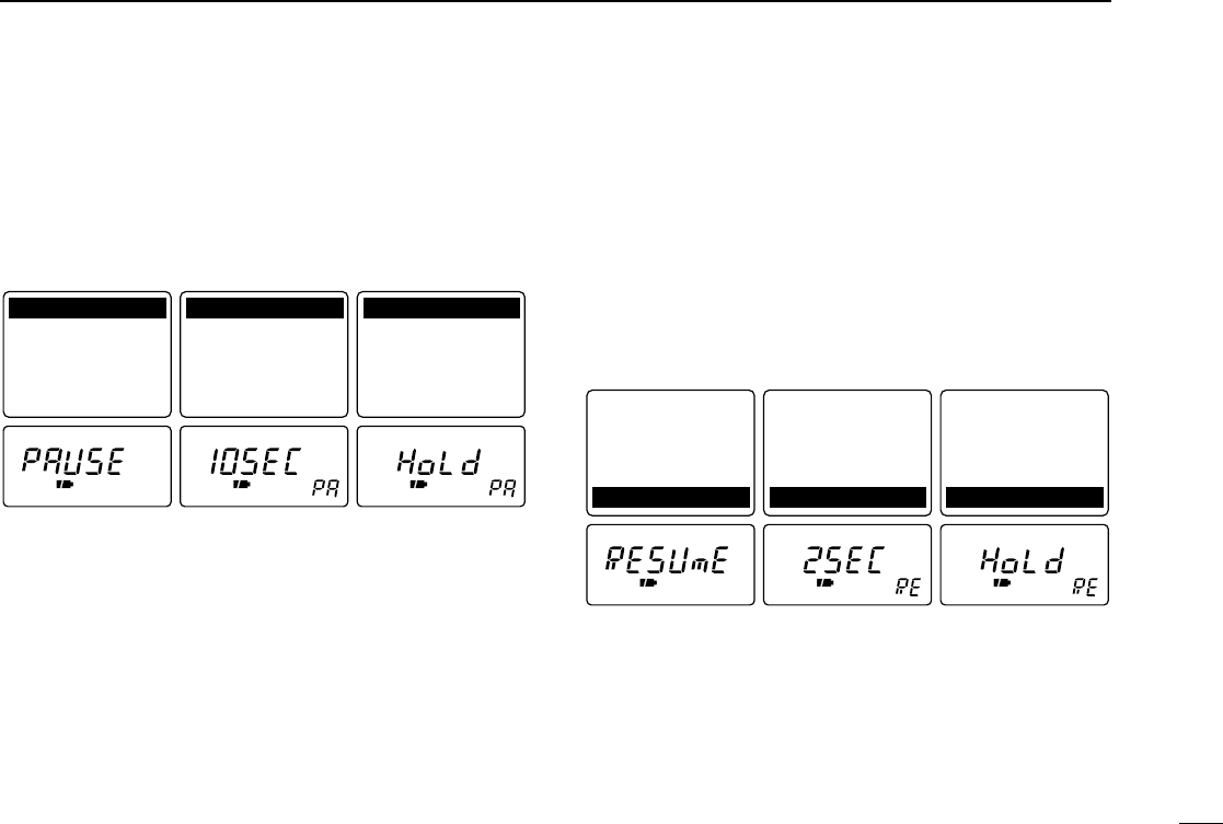
■Scan resume condition
◊Setting the scan pause time
The scan pauses when receiving signals according to the
scan pause time. It can be set from 2–20 sec. or unlimited.
qPush [FUNC] + [(MODE)SET] momentarily to enter set
mode.
•Select a non-band scope screen in advance for color LCD.
wRotate [DIAL] until “Pause Scan”or “PAUSE”appears.
•“PAUSE”disappears after 1 sec. and the previously selected
scan pause time and “PA”appears when color LCD is OFF.
FM FM FM
P
S1 3 5 7 9
VOL
FM
146.010.000
M:A00
TS 15.0
S1 3 5 7 9
VOL
FM SKIP
146.010.000
M:A00
TS 15.0
S1 3 5 7 9
VOL
FM PSKIP
146.010.000
M:A00
TS 15.0
Skip channelNon-skip channel
Skip channel and
frequency skip channel
23
6
SCAN OPERATION
ePush [↔] or rotate the tuning dial while pushing [FUNC] to
select the desired scan pause time.
•“2SEC”–“20SEC”: scan pauses for 2–20 sec. on a received sig-
nal.
•“HOLD”: scan pauses on a received signal until it dis-
appears.
rPush [(MODE)SET] to exit set mode.
◊Setting the scan resume time
The scan restarts after a signal disappears according to the
resume time. It can be set from 0–5 sec. or unlimited.
qPush [FUNC] + [(MODE)SET] momentarily to enter set
mode.
•Select a non-band scope screen in advance for color LCD.
wRotate [DIAL] until “Scan Resume”or “RESUmE”appears.
•“RESUmE”disappears after 1 sec. and the previously selected
scan resume time and “RE”appears when color LCD is OFF.
ePush [↔] or rotate the tuning dial while pushing [FUNC] to
select the desired scan resume time.
•“1SEC”–“5SEC”: scan restarts 1–5 sec. after the signal disap-
pears.
•“0SEC”: scan restarts immediately after the signal dis-
appears.
•“HOLD”: scan restarts by rotating [DIAL] only.
rPush [(MODE)SET] to exit set mode.
2 sec. resume timeScan resume time
set mode Scan resumes by
rotating [DIAL] only.
Tone Squelch: OFF
Tone Freq. : 88.5
Duplex : OFF
Offset Freq.: 0.600
Scan Resume : 2SEC
Tone Squelch: OFF
Tone Freq. : 88.5
Duplex : OFF
Offset Freq.: 0.600
Scan Resume : 2SEC
Tone Squelch: OFF
Tone Freq. : 88.5
Duplex : OFF
Offset Freq.: 0.600
Scan Resume : HOLD
10 sec. pause timeScan pause time set
mode Pause scan
Pause Scan : 10SEC
Priority : OFF
Beep Audio : VOLUME
Light : AUTO
A.Power OFF : OFF
Pause Scan : 10SEC
Priority : OFF
Beep Audio : VOLUME
Light : AUTO
A.Power OFF : OFF
Pause Scan : HOLD
Priority : OFF
Beep Audio : VOLUME
Light : AUTO
A.Power OFF : OFF
24
6SCAN OPERATION
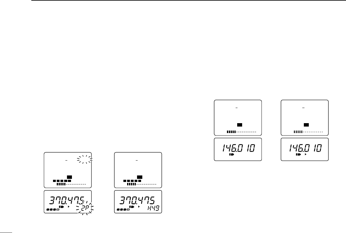
■Frequency skip function
◊Programming a skip frequency
Unwanted frequencies can be skipped and programmed as
skip channels when full scan, band scan or programmed scan
is pausing.
qStart full scan, band scan or programmed scan. (p. 19)
wWhile receiving an unwanted signal and scan pauses,
push [FUNC] + [(V/M)SKIP] for 2 sec. to program the re-
ceived frequency as a skip frequency.
•The receiver emits 3 beeps and the scan resumes.
•Non-programmed memory channels (blank channels) are used
for skip frequency programming in reverse sequence.
•To scan the skip frequency after programming, cancel the skip
information (p. 22) or clear the memory channel (p. 16).
◊Frequency skip function ON/OFF
The frequency skip function can be turned OFF. In this case,
the frequencies will not be skipped even if skip information is
programmed and “P SKIP”or “P"”does not appear.
qSelect VFO mode with [V/M].
wPush [FUNC] + [(V/M)SKIP] to toggle the frequency skip
function ON or OFF.
•“PSKIP”or “P"”appears when the function is turned ON.
FM FM
P
S1 3 5 7 9
VOL
FM
146.010.000
TS 15.0
S1 3 5 7 9
VOL
FM PSKIP
146.010.000
TS 15.0
The frequency skip
function is OFF. The frequency skip
function is ON.
FM
P
RX
FM
P
RX
S1 3 5 7 9
VOL
RX
FM PSKIP
370.475.000
2P
TS 15.0
S1 3 5 7 9
VOL
RX
FM PSKIP
370.475.000
H49
TS 15.0
Indication while programmingIndication while pausing
25
7
PRIORITY WATCH
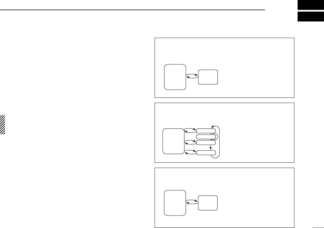
■Priority watch types
Priority watch checks for signals on a frequency every 5 sec.
while operating on a VFO frequency or scanning.The receiver
has 3 priority watch types to suit your needs.
In addition, you can be alerted with beeps and a flashing “ë.”
The watch resumes according to the selected scan resume
condition. See p. 22 for details.
If the pocket beep function is activated, the receiver auto-
matically selects the tone squelch function when priority
watch starts.
MEMORY CHANNEL
WATCH (p. 26)
While operating on a VFO
frequency, priority watch
checks for a signal on the
selected memory channel
every 5 sec.
•A memory channel with skip in-
formation can be watched.
MEMORY SCAN WATCH
(p. 26)
While operating on a VFO
frequency, priority watch
checks for signals on each
memory channel in se-
quence.
•The memory skip function
and/or memory bank scan is
useful to speed up the scan.
VFO SCAN WATCH (p. 27) While scanning in VFO
mode, priority watch checks
for signals on the selected
memory channel every 5
sec.
Memory
channel
VFO
frequency
5 sec. 125 msec.
VFO
frequency
Mch 01
Mch 00
Mch 02
Mch 49
5 sec. 125 msec.
SKIP
VFO
scanning Memory
channel
5 sec. 125 msec.
26
7PRIORITY WATCH
■Priority watch operation
◊Memory channel watch and memory scan
watch
qSelect VFO mode; then, set an operating frequency.
wSet the watching channel(s).
For memory channel watch:
Select the desired memory channel.
For memory scan watch:
Select memory mode; then, push [↔] for 2 sec. to start
memory scan.
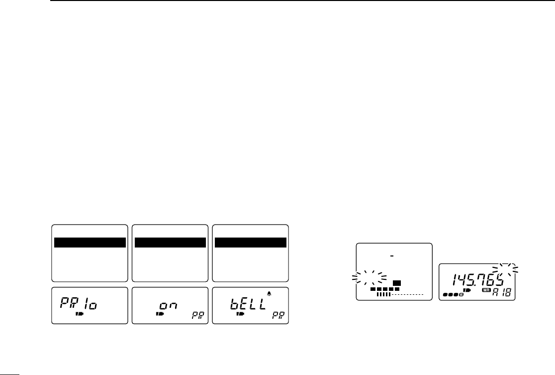
ePush [FUNC] + [(MODE)SET] momentarily to enter set
mode.
•Select a non-band scope screen in advance for color LCD.
rRotate [DIAL] to select “Priority”or “PRIo.”
•“PRIo”disappears after 1 sec. and “oFF”and “PR”appears when
color LCD is OFF.
tPush [↔] or rotate the tuning dial while pushing [FUNC] to
select priority watch ON or priority watch ON with alert
(BELL).
•If the pocket beep function is activated, the receiver automatically
selects the tone squelch function when the priority watch is se-
lected.
yPush [(MODE)SET] to exit set mode and start the watch.
•The receiver checks the memory channel frequency every 5 sec.
•The watch resumes according to the selected scan resume con-
dition. (p. 22)
•If the priority watch with alert is ON, you can be alerted with
beeps and a flashing “P. B ”or “ë.”
•If the direction finding screen is selected, the receiver automati-
cally selects the simple screen when the priority watch starts.
uPush [V/M] while the display shows the VFO frequency to
stop the watch.
FM PRIO
RX
S1 3 5 7 9
VOL
RX
FM
145.765.000
M:A18
PRIO
TS 15.0
While pausing on the memory channel,
“PRIO” flashes.
Priority watch set
mode
Pause Scan : 10SEC
Priority : OFF
Beep Audio : VOLUME
Light : AUTO
A.Power OFF : OFF
Pause Scan : 10SEC
Priority : ON
Beep Audio : VOLUME
Light : AUTO
A.Power OFF : OFF
Pause Scan : 10SEC
Priority : BELL
Beep Audio : VOLUME
Light : AUTO
A.Power OFF : OFF
Priority watch is ON. Priority watch with
alert is ON.
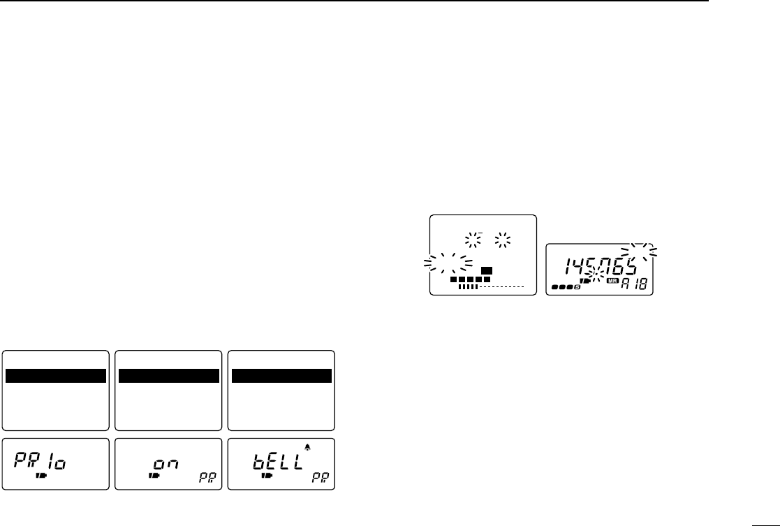
◊VFO scan watch
qSelect the desired memory channel to be watched.
wPush [V/M] to select VFO mode.
ePush [↔] for 2 sec. to start full scan, band scan or pro-
grammed scan. (p. 19)
rPush [FUNC] + [(MODE)SET] momentarily to enter set
mode.
•Select a non-band scope screen in advance for color LCD.
tRotate [DIAL] to select “Priority”or “PRIo.”
•“PRIo”disappears after 1 sec. and “oFF”and “PR”appears when
color LCD is OFF.
yPush [↔] or rotate the tuning dial while pushing [FUNC] to
select priority watch ON or priority watch ON with alert
(BELL).
•If the pocket beep function is activated, the receiver automatically
selects the tone squelch function when the priority watch is se-
lected.
uPush [(MODE)SET] to exit set mode and start the watch.
•The receiver checks the memory channel frequency every 5 sec.
•The watch resumes according to the selected scan resume con-
dition. (p. 22)
•If the priority watch with alert is ON, you can be alerted with
beeps and a flashing “P. B ”or “ë.”
•If the direction finding screen is selected, the receiver automati-
cally selects the simple screen when the priority watch starts.
iPush [V/M] while the display shows the VFO frequency to
stop the watch.
FM PRIO
RX
S1 3 5 7 9
VOL
RX
FM
145.765.000
M:A18
PRIO
ALL
TS 15.0
While pausing on the memory channel,
“PRIO” flashes.
Priority watch set
mode
Pause Scan : 10SEC
Priority : OFF
Beep Audio : VOLUME
Light : AUTO
A.Power OFF : OFF
Pause Scan : 10SEC
Priority : ON
Beep Audio : VOLUME
Light : AUTO
A.Power OFF : OFF
Pause Scan : 10SEC
Priority : BELL
Beep Audio : VOLUME
Light : AUTO
A.Power OFF : OFF
Priority watch is ON. Priority watch with
alert is ON.
27
7
PRIORITY WATCH
28
8SUBAUDIBLE TONE OPERATION
■Tone squelch operation
◊Operation
The tone squelch opens only when receiving a signal con-
taining a matching subaudible tone. You can silently wait for
calls from group members using the same tone in an ama-
teur band.
qSet the operating frequency in FM mode.
wSet the desired subaudible tone in set mode.
•See the following section for programming.
ePush [FUNC] + [(MODE)SET] momentarily to enter set
mode.
•Select a non-band scope screen in advance for color LCD.
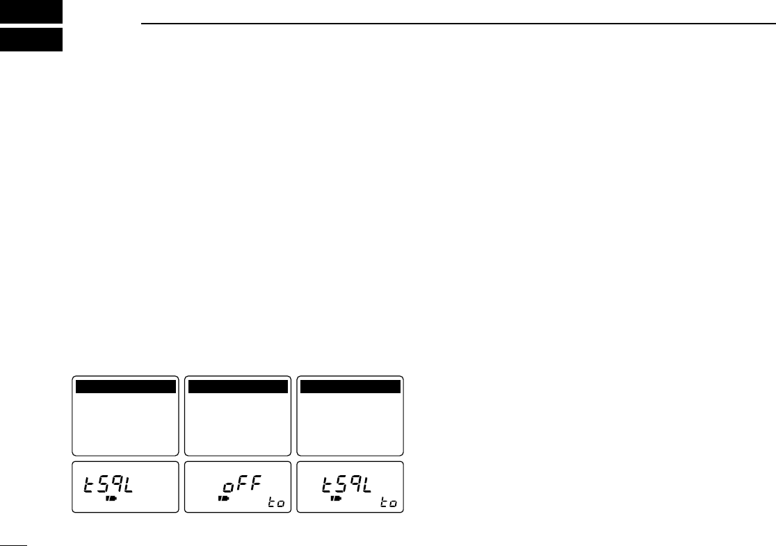
rRotate [DIAL] until “Tone Squelch”or “tSqL”appears.
•“tSqL”disappears after 1 sec. and “to”appears when color LCD is
OFF.
tPush [↔] or rotate the tuning dial while pushing [FUNC] to
select “TSQL”(tone squelch).
yPush [(MODE)SET] to exit set mode and start the tone
squelch.
uWhen the received signal includes a matching tone, the
squelch opens and the signal can be heard.
•When the received signal’s tone does not match, tone squelch
does not open, however, the S-indicator shows signal strength.
•To open the squelch manually, push and hold [SQL]. (default)
iTo cancel the tone squelch, repeat steps e–yas de-
scribed above and select “OFF”in step t.
◊Setting subaudible tones for tone squelch
operation
qSelect VFO mode or desired memory channel to be pro-
grammed.
•Each operating band and each memory channel have indepen-
dent settings.
wPush [FUNC] + [(MODE)SET] momentarily to enter set
mode.
•Select a non-band scope screen in advance for color LCD.
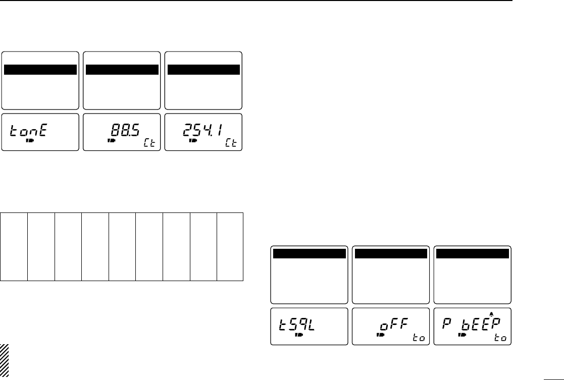
eRotate [DIAL] until “Tone Freq.”or “tonE”appears.
•“tonE”disappears after 1 sec. and “Ct”appears.
rPush [↔] or rotate the tuning dial while pushing [FUNC] to
select a subaudible tone.
tPush [(MODE)SET] to exit set mode.
Tone function set
mode
Tone Squelch: OFF
Tone Freq. : 88.5
Duplex : OFF
Offset Freq.: 0.600
Scan Resume : 2SEC
Tone Squelch: OFF
Tone Freq. : 88.5
Duplex : OFF
Offset Freq.: 0.600
Scan Resume : 2SEC
Tone Squelch: TSQL
Tone Freq. : 88.5
Duplex : OFF
Offset Freq.: 0.600
Scan Resume : 2SEC
Tone squelch OFF Tone squelch ON
•Available subaudible tone frequencies (unit: Hz)
"CONVENIENT
Store subaudible tone frequencies and tone squelch ON/OFF
settings in memories for easy recall.
The receiver has 50 tone frequencies and consequently
their spacing is narrow. Therefore, some tone frequencies
may receive interference from adjacent ones.
■Pocket beep operation
This function uses subaudible tones for calling and can be
used as a “common pager”to inform you that someone has
called using the same tone in an amateur band while you
were away from the receiver.
◊Waiting for a call from a specific station
qSet the operating frequency in FM mode.
wSet the desired tone squelch tone in set mode.
•See the previous page for programming information.
eTurn the priority watch OFF when used. (p. 26)
•The pocket beep cannot be used with the priority watch.
rPush [FUNC] + [(MODE)SET] momentarily to enter set
mode.
•Select a non-band scope screen in advance for color LCD.
TSQL
Tone function set
mode
Tone Squelch: OFF
Tone Freq. : 88.5
Duplex : OFF
Offset Freq.: 0.600
Scan Resume : 2SEC
Tone Squelch: OFF
Tone Freq. : 88.5
Duplex : OFF
Offset Freq.: 0.600
Scan Resume : 2SEC
Tone Squelch: P BEEP
Tone Freq. : 88.5
Duplex : OFF
Offset Freq.: 0.600
Scan Resume : 2SEC
Tone function OFF Pocket beep ON
Tone frequency set
mode
Tone Squelch: TSQL
Tone Freq. : 88.5
Duplex : OFF
Offset Freq.: 0.600
Scan Resume : 2SEC
Tone Squelch: TSQL
Tone Freq. : 88.5
Duplex : OFF
Offset Freq.: 0.600
Scan Resume : 2SEC
Tone Squelch: TSQL
Tone Freq. : 254.1
Duplex : OFF
Offset Freq.: 0.600
Scan Resume : 2SEC
88.5 Hz (default) 254.1 Hz tone
29
8
SUBAUDIBLE TONE OPERATION
67.0
69.3
71.9
74.4
77.0
79.7
82.5
85.4
88.5
91.5
94.8
97.4
100.0
103.5
107.2
110.9
114.8
118.8
123.0
127.3
131.8
136.5
141.3
146.2
151.4
156.7
159.8
162.2
165.5
167.9
171.3
173.8
177.3
179.9
183.5
186.2
189.9
192.8
196.6
199.5
203.5
206.5
210.7
218.1
225.7
229.1
233.6
241.8
250.3
254.1
30
8SUBAUDIBLE TONE OPERATION
tRotate [DIAL] until “Tone Squelch”or “tSqL”appears.
•“tSqL”disappears after 1 sec. and “to”appears when color LCD is
OFF.
yPush [↔] or rotate the tuning dial while pushing [FUNC] to
select “P BEEP”(pocket beep).
uPush [(MODE)SET] to exit set mode and start the pocket
beep.
•“P. B ”or “TSQL ë”appears in the function display.
iWhen a signal with the correct tone is received, the re-
ceiver emits beep tones for 30 sec. and flashes “P.B”or
“ë.”
oPush [SQL] to stop the beeps and flashing.
•Tone squelch is automatically selected.
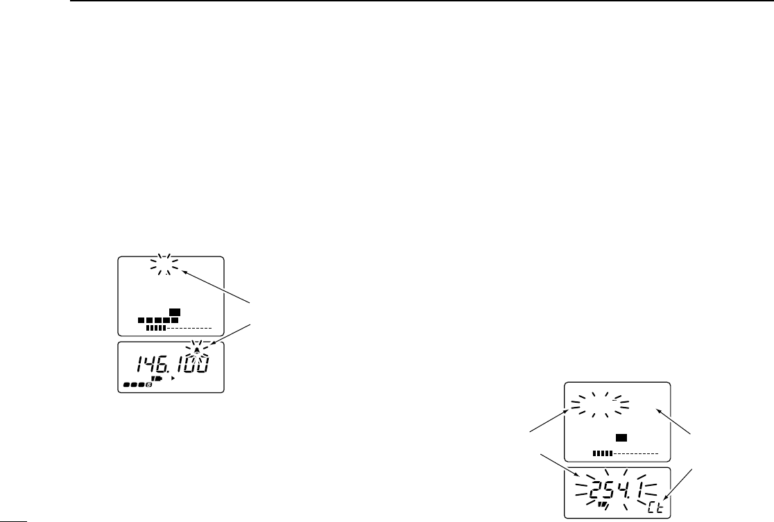
■Tone scan
The receiver can detect the subaudible tone frequency in a
received signal. By monitoring a signal that is being transmit-
ted on a frequency, you can check the tone frequency re-
quired to access the repeater, or to open the tone squelch.
qSet the desired frequency or memory channel to be
checked for a tone frequency.
wSelect FM mode with [MODE].
ePush [FUNC] + [↔] for 2 sec. to start the tone scan.
•To change the scanning direction, rotate [DIAL].
rWhen the tone frequency is detected, the set mode con-
tents are programmed with the tone frequency.
•The tone scan pauses when a tone frequency is detected.
•The detected tone frequency is used for the tone squelch fre-
quency.
•“Ct”appears during tone scan.
tPush [↔] to stop the scan.
S1 3 5 7 9
VOL
FM
146.1 CT
TS 15.0
“Ct” appears
during tone
scan.
Tone frequencies
flash as they are
scanned.
flashes when correct
tone is received.
TSQLFM
P
S1 3 5 7 9
VOL
RX
FM P.B
146.100.000
TS 15.0
RX
31
9
DUPLEX OPERATION
Duplex communication uses 2 different frequencies for trans-
mitting and receiving. Generally, duplex is used in communi-
cation through a repeater, some utility communications, etc.
During duplex operation, the transmit station frequency is
shifted from the receive station frequency by the offset fre-
quency. Repeater information (offset frequency and shift di-
rection) can be programmed into memory channels. (p. 14)
This function is not available in the broadcast band (0.495
–1.620 MHz) except for U.S.A. and Canada versions.
qSet the receive station frequency (repeater output fre-
quency).
wSet the shift direction and offset of the transmit station fre-
quency as described below.
ePush and hold [SQL] to monitor the transmit station fre-
quency (repeater input frequency) directly.
◊Duplex shift direction
qPush [FUNC] + [(MODE)SET] momentarily to enter set
mode.
•Select a non-band scope screen in advance for color LCD.
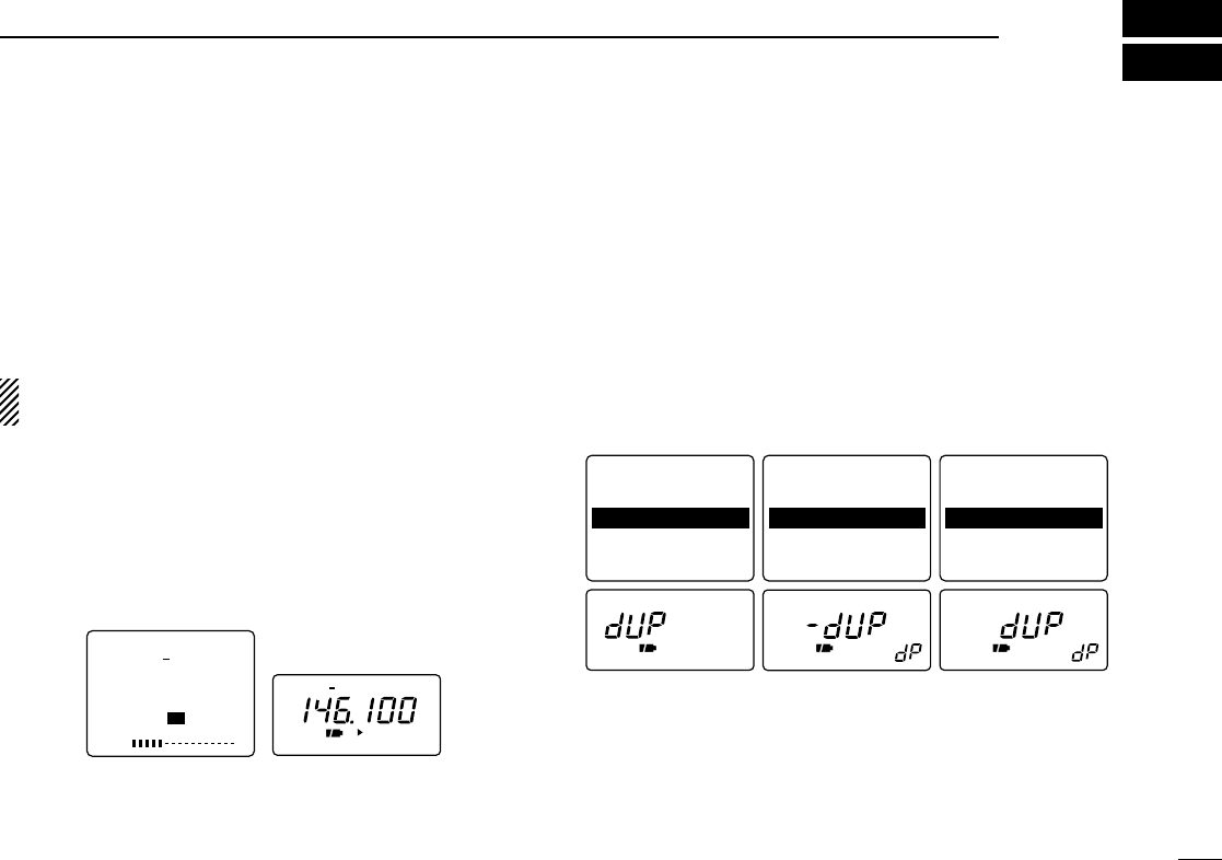
wRotate [DIAL] until “Duplex”or “dUP”appears.
•“dUP”disappears after 1 sec. and “dP”appears when color LCD
is OFF.
ePush [↔] or rotate the tuning dial while pushing [FUNC] to
select “–DUP”or “(+)DUP.”
•“–DUP”or “(+)DUP”indicates the transmit station frequency for
minus shift or plus shift, respectively.
rPush [(MODE)SET] to exit set mode.
Duplex direction set
mode
Tone Squelch: OFF
Tone Freq. : 88.5
Duplex : OFF
Offset Freq.: 0.600
Scan Resume : 2SEC
Tone Squelch: OFF
Tone Freq. : 88.5
Duplex : -DUP
Offset Freq.: 0.600
Scan Resume : 2SEC
Tone Squelch: OFF
Tone Freq. : 88.5
Duplex : +DUP
Offset Freq.: 0.600
Scan Resume : 2SEC
Minus shift Plus shift
FM
P
S1 3 5 7 9
VOL
FM
146.100.000
TS 15.0
DUP
–DUP
32
9DUPLEX OPERATION
◊Offset frequency
During duplex operation, the transmit station frequency is
shifted from the receive station frequency by an amount de-
termined by the offset frequency.
qSelect VFO mode or desired memory channel to be pro-
grammed.
wPush [FUNC] + [(MODE)SET] momentarily to enter set
mode.
•Select a non-band scope screen in advance for color LCD.
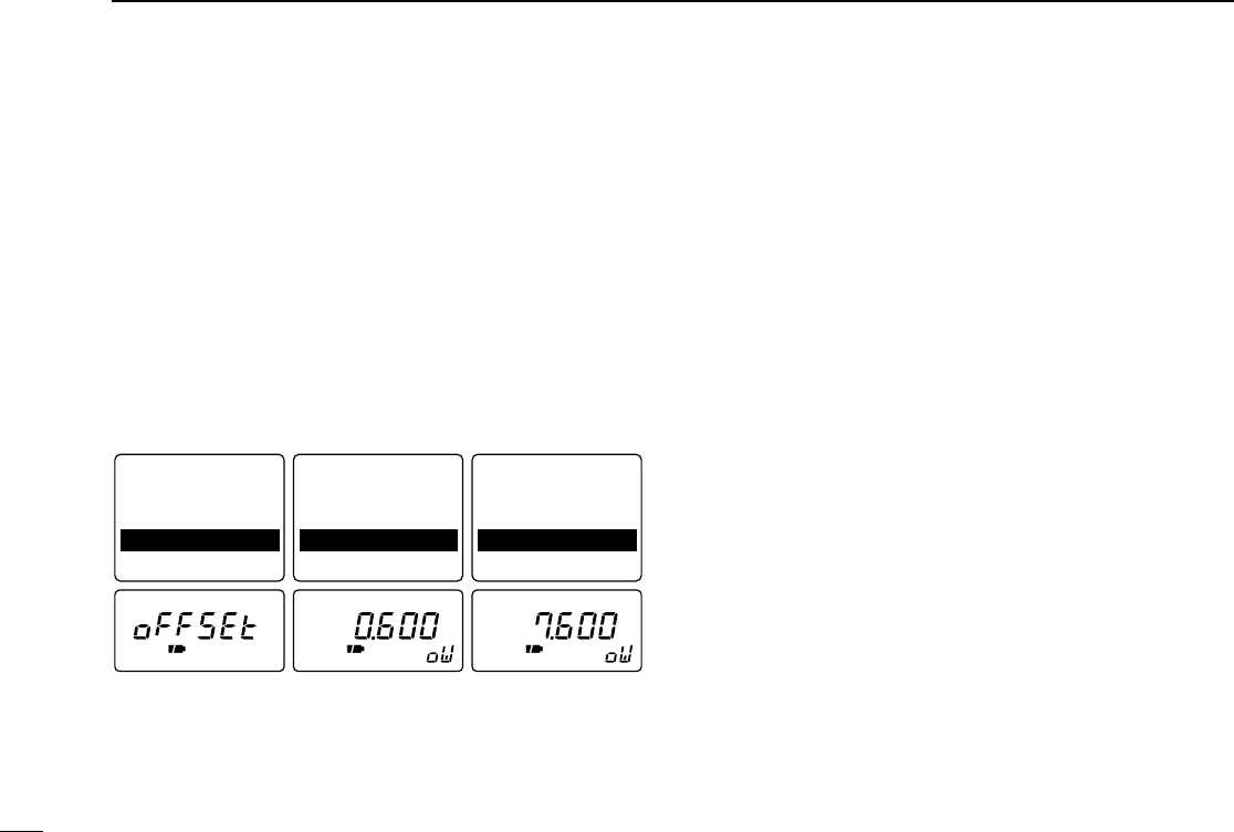
eRotate [DIAL] until “Offset Freq.”or “oFFSEt”appears.
•“oFFSEt”disappears after 1 sec. and “oW”appears when the
color LCD is OFF.
rPush [↔] or rotate the tuning dial while pushing [FUNC] to
set the desired offset.
•The offset frequency changes according to the selected tuning
step. (p. 8)
tPush [(MODE)SET] to exit set mode.
Offset frequency set
mode
Tone Squelch: OFF
Tone Freq. : 88.5
Duplex : OFF
Offset Freq.: 0.600
Scan Resume : 2SEC
Tone Squelch: OFF
Tone Freq. : 88.5
Duplex : OFF
Offset Freq.: 0.600
Scan Resume : 2SEC
Tone Squelch: OFF
Tone Freq. : 88.5
Duplex : OFF
Offset Freq.: 7.600
Scan Resume : 2SEC
0.6 MHz (600 kHz)
offset 7.6 MHz offset
33
10
BAND SCOPE
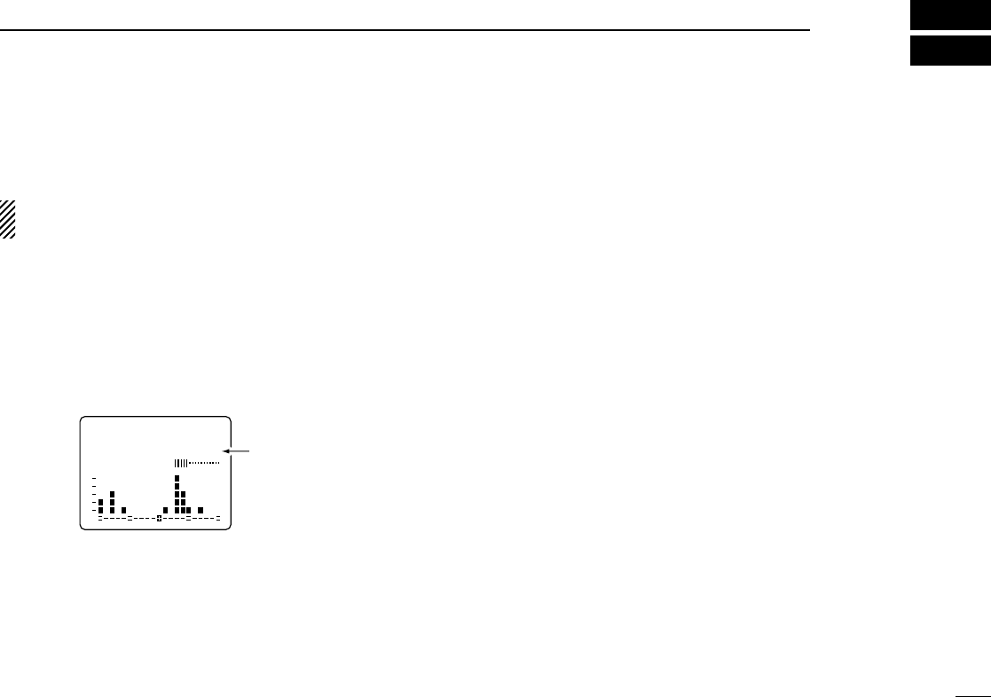
The band scope function allows you to visually check a spec-
ified frequency range. Sweep range can be selected from ±5
kHz through ±500 kHz.
Receive audio is muted while monitoring the band scope.
Push [SQL] to cancel sweeping and receive the audio.
qPush [FUNC] + [↕] for 2 sec. to turn the color LCD ON.
wPush [FUNC] + [↕] one or more times to select the band
scope screen.
eSet the desired frequency as band scope center frequency.
rPush [FUNC] + [V/M] momentarily to select the sweep
range, if desired.
•5, 10, 20, 100 and 500 kHz sweep ranges are available.
tPush [FUNC] + [V/M] momentarily to start a sweep once
or push them for 2 sec. to start sweeping continuously.
•Signal conditions (strengths) appear starting from the center of
the range.
•Push [SQL] to cancel sweeping.
yRotate [DIAL] to set the highlighted cursor to the desired
waveform and set the frequency of the signal.
•Start sweeping to set the selected frequency to the center fre-
quency.
FM
146.100.000 TS= 25.0
SWEEP-500kS1 3 5 7 9 VOL
Sweep range
34
11 TV OPERATION
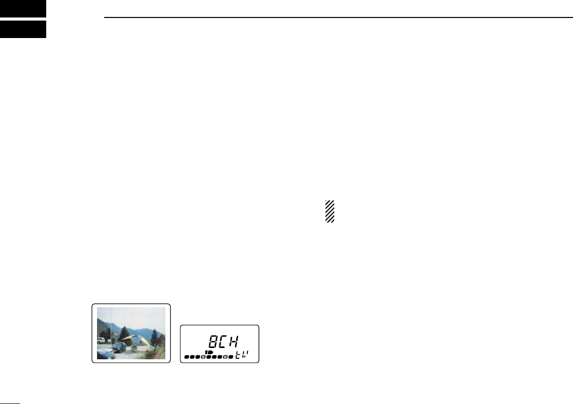
■TV operation
The receiver can receive TV (NTSC or PAL depending on ver-
sion). TV channels are preset depending on versions.
The received video and audio can be output from [A/V OUT] if
desired.
◊TV channel receiving
qPush [FUNC] + [↕] for 2 sec. to turn the color LCD ON, if
desired.
•Only the audio part of the TV contents can be received.
wPush [↔] one or more times to select the TV channel
band.
•“tV”and channel number appear in the sub LCD.
•The squelch is automatically opened. Push [SQL] to toggle be-
tween squelch open and audio mute conditions.
eRotate [DIAL] to select the desired channel.
•Rotate [DIAL] while pushing [FUNC] to select the skip channel.
◊Skip channel setting
Unwanted channels can be skipped for rapid selection, etc.
qRotate [DIAL] to select the channel to be skipped.
•To clear the skip setting, rotate [DIAL] while pushing [FUNC] to
select a skip channel.
wWhile pushing [FUNC], push [(V/M)SKIP] for 2 sec. to tog-
gle the condition between non-skip and skip channel.
•No indication : channel will not be skipped.
•“"”appears : channel skipped during selection.
To select a skip TV channel temporarily, rotate [DIAL] while
pushing [FUNC].
◊Automatic TV channel programming
TV channels can be programmed automatically.
qPush [FUNC] + [↔] for 2 sec. to start TV channel pro-
gramming.
wThe programming will automatically stop after scanning all
channels.
FM
W
RX
35
11
TV OPERATION
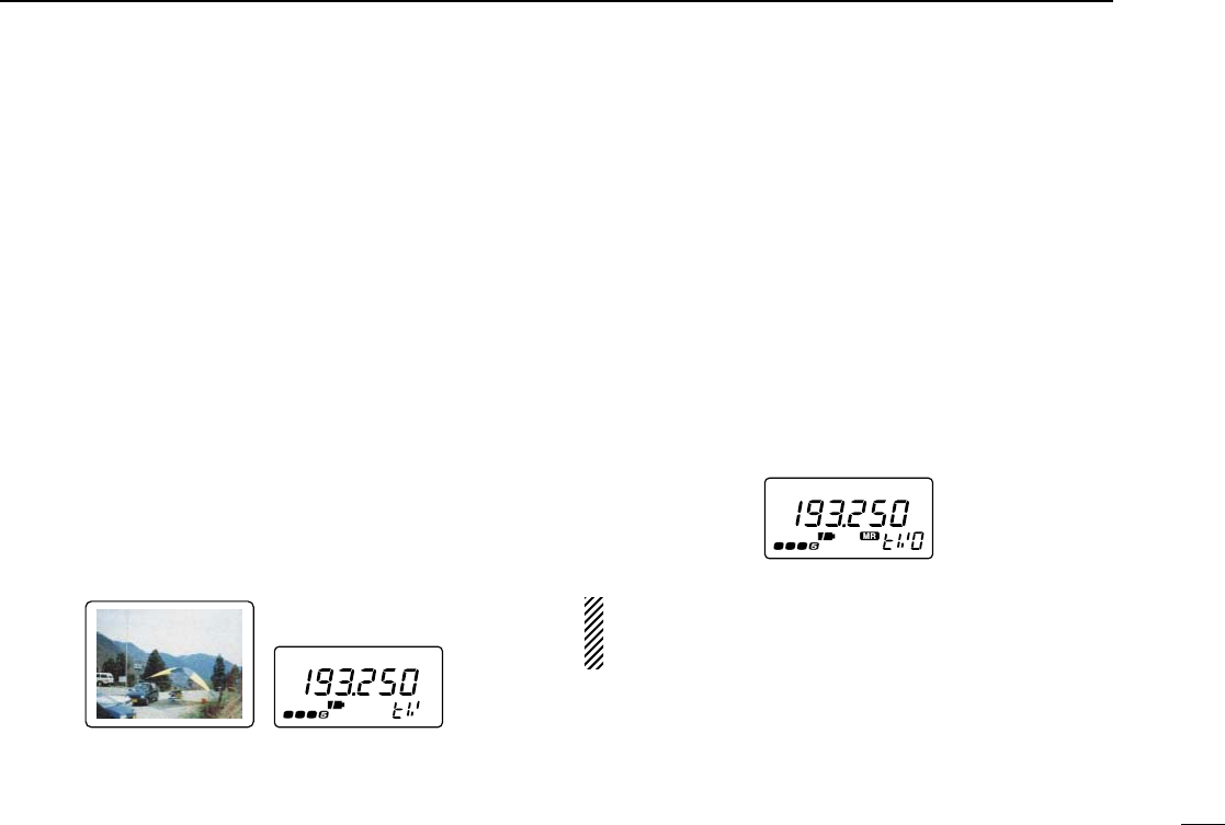
◊TV frequency (AM TV) receiving
You can set the TV frequency instead of channel selection, if
desired.
qPush [FUNC] + [↕] for 2 sec. to turn the color LCD ON, if
desired.
•The audio part of the TV contents can be received when the
color LCD is turned OFF.
wPush [↔] one or more times to select the band above 30
MHz.
•TV receiving does not function for less than 30 MHz.
ePush [FUNC] + [↕] one or more times to select the TV
screen.
•“tV”and frequency appear in the sub LCD.
•The squelch is automatically opened. Push [SQL] to toggle be-
tween squelch open and audio mute conditions.
rRotate [DIAL] to set the desired frequency.
•Push [↔] one or more times to select the band.
•Rotate [DIAL] while pushing [FUNC] for dial select step. (p. 39)
◊TV frequency (AM TV) memory channel
The receiver has 10 memory channels for storage of often-
used TV (AM TV) frequencies.
qSet the desired frequency with [DIAL].
•Push [↔] one or more times to select the band.
•Rotate [DIAL] while pushing [FUNC] for dial select step. (p. 39)
wPush [V/M] for 1 sec. to indicate memory channels.
•Do not hold [V/M] for more than 2 sec., otherwise the previously
selected memory channel will be overwritten.
eRotate [DIAL] to select the desired channel.
rPush [V/M] for 1 sec. to program.
•Keep pushing for 2 sec. or more to automatically select the next
memory channel, if desired.
Memory programming after selection, memory transferring
or memory clearing can be used as same manner of regu-
lar memory channels. (pgs. 15, 16)
FM
W
RX
FM
W
RX
36
11 TV OPERATION
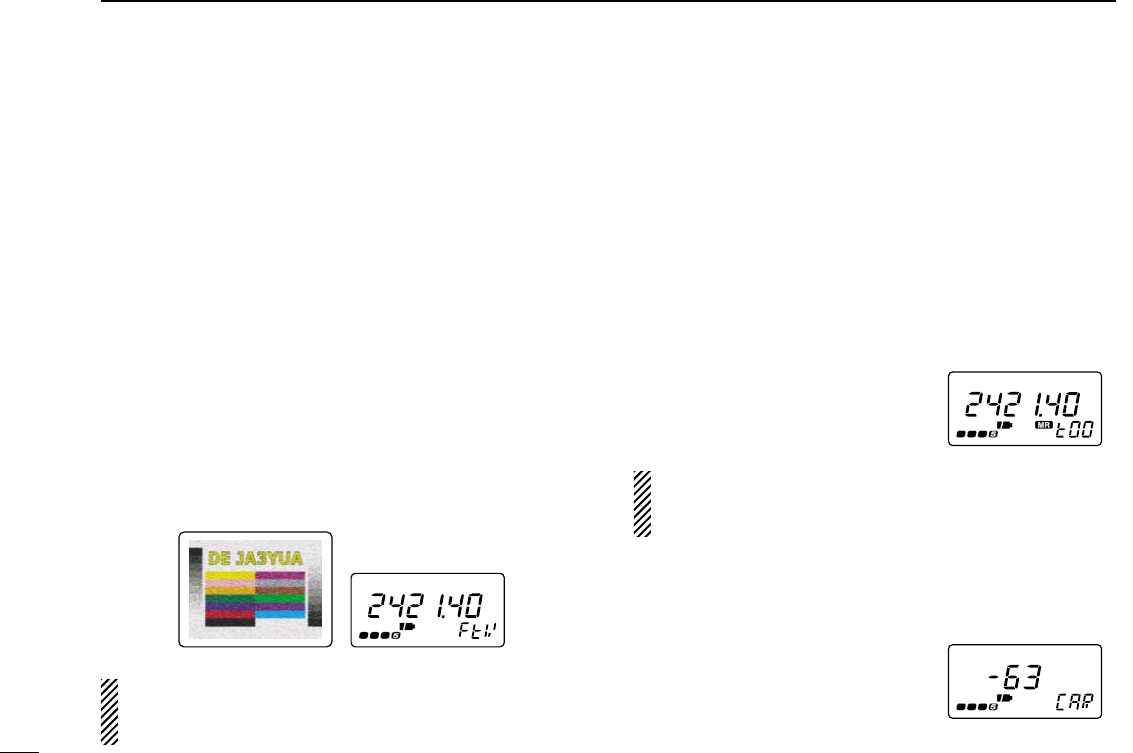
■ATV operation
The IC-R3 ATV-type can receive an amateur TV (FM TV)
within 900–1300 and 2250–2450.095 MHz. The received
video and audio can be output from [A/V OUT] if desired. (p.
5)
qPush [FUNC] + [↕] for 2 sec. to turn the color LCD ON, if
desired.
•Only the audio part of the TV contents can be received.
wPush [↔] one or more times to select the 1200 or 2400
MHz bands.
ePush [FUNC] + [↕] one or more times to select the ama-
teur TV screen.
•“FtV”and frequency appear in the sub LCD.
•The squelch is automatically opened. Push [SQL] to toggle be-
tween squelch open and audio mute conditions.
rRotate [DIAL] to set the desired frequency.
The video display mode can be selected as positive and
negative depending on the received signal. Push [MODE]
to toggle the display mode, if desired.
◊ATV memory channel
The receiver has 50 memory channels for storage of often-
used ATV (Amateur TV) frequencies.
qSet the desired frequency with [DIAL].
•Push [↔] to select the 1200 or 2400 MHz band.
•Rotate [DIAL] while pushing [FUNC] for dial select step. (p. 39)
wPush [V/M] for 1 sec. to indicate memory channels.
•Do not hold [V/M] for more than 2 sec., otherwise the previously
selected memory channel will be overwritten.
eRotate [DIAL] to select the desired channel.
rPush [V/M] for 1 sec. to program.
•Keep pushing for 2 sec. or more to
automatically select the next mem-
ory channel, if desired.
Memory programming after selection, memory transferring
or memory clearing can be used as same manner of regu-
lar memory channels. (pgs. 15, 16)
◊Sub carrier adjustment
qPush [FUNC] + [↔] for 2 sec. to enter sub carrier set
mode.
wPush [↔] or rotate the tuning dial
while pushing [FUNC] to adjust
sub carrier for better audio re-
ceiving.
ePush [↔] to exit sub carrier set mode.
FM
W
RX
FM
W
RX
RX
37
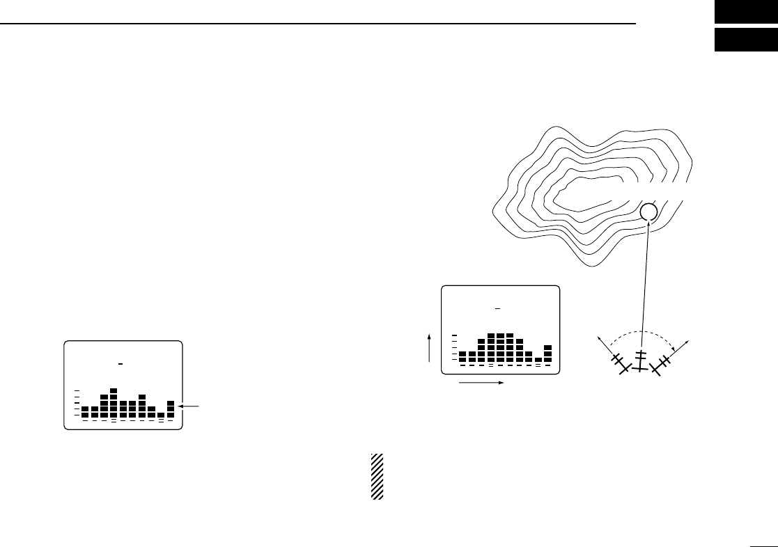
12
DIRECTION FINDING
The direction finding function allows you to check a variation
of the signal level continuously.
Using a commercially available directional antenna, you can
determine the direction of the signal source. Using 2 receivers
with the directional antennas, you can pinpoint the signal
source.
qPush [FUNC] + [↕] for 2 sec. to turn the color LCD ON.
wPush [FUNC] + [↕] one or more times to select the direction
finding screen.
eSet the desired frequency.
•The color LCD shows the variation of the signal level.
•If the strong signal is received on 1149.995 MHz or below, use
the attenuator function. (p. 9)
rTurn around the directional antenna for maximum receive
level.
tThe direction (or opposite) of the maximum receive level
may indicate the signal source direction.
•Direction finding function example
The direction finding function is a supplemental aid for find-
ing a signal source only. It is not designed for use as a
compass.
FM
146.100.000
15.0
TS
Signal source
IC-R3
Signal
levels
Time
FM
146.100.000
15.0
TS
Signal levels
38
13 OTHER FUNCTIONS
■Set mode
Set mode is used for programming infrequently changed val-
ues or conditions of functions.
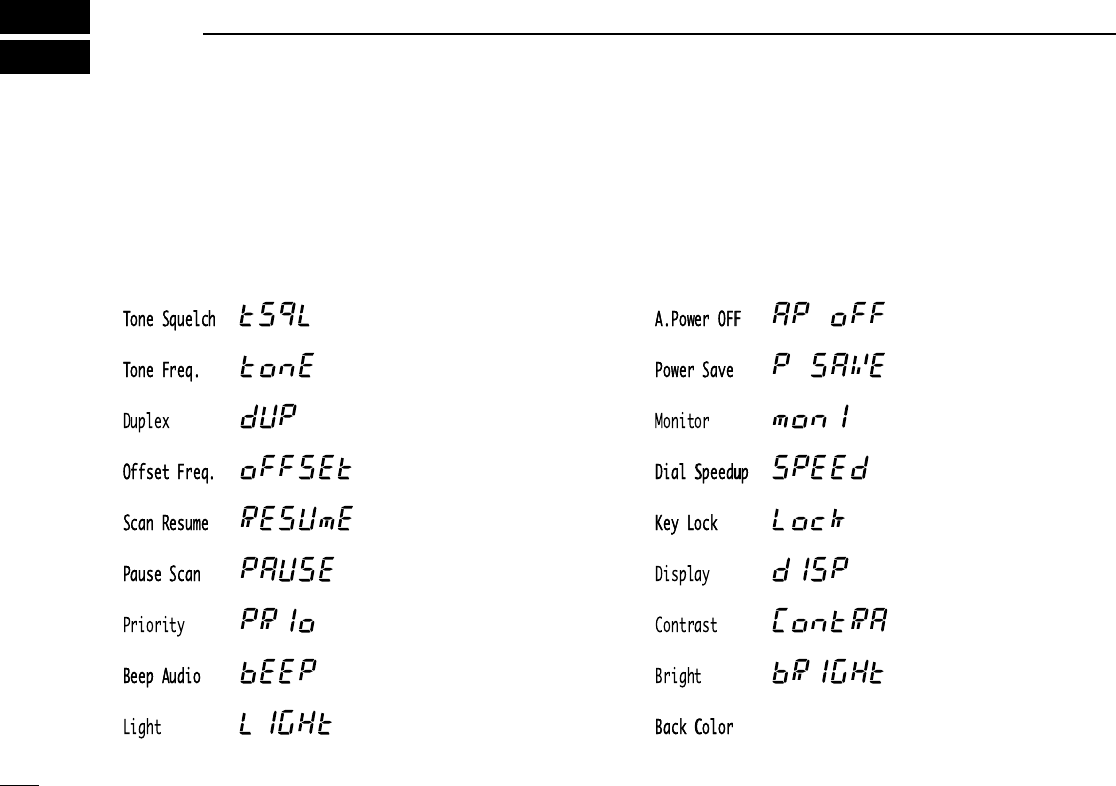
◊Set mode items
L: Appears when the color LCD is ON.
T: Appears when receiving TV.
B: Does not appear within the broadcast band (0.495–1.620 MHz)
except for U.S.A. and Canada versions
Tone squelch (p. 28)
Tone squelch tone
frequency (p. 28)
Duplex direction (p. 31)
Offset frequency (p. 32)
Scan resume time (p. 23)
Scan pause time (p. 22)
Priority watch (p. 26)
Confirmation beep (p. 40)
Backlighting (p. 13)
Auto power OFF (p. 40)
Power save (p. 41)
Monitor switch action
(p. 41)
Dial speed (p. 42)
Lock function effect (p. 42)
Display mode (p. 43)
Color LCD contrast (p. 43)
(Color LCD only)
Color LCD brightness
(p. 44)
Color LCD background
color (p. 44)
B
B
LT
TL
L
39
13
OTHER FUNCTIONS
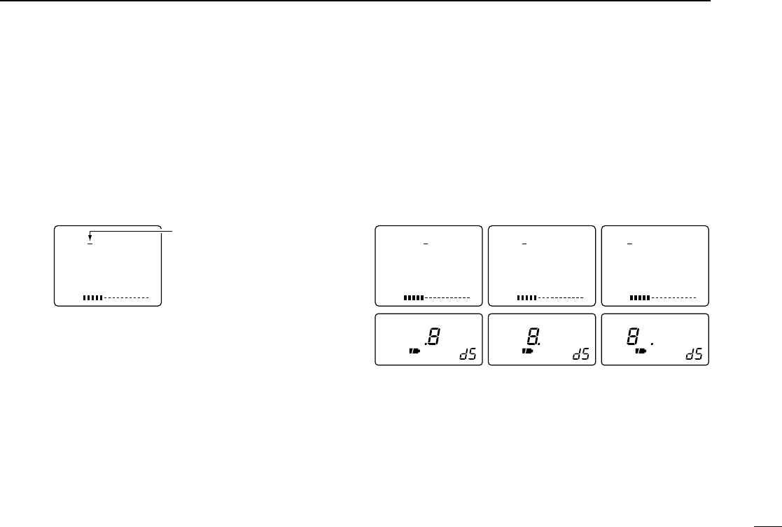
■Dial select step
This receiver has a 1 MHz tuning step for quick frequency set-
ting. This dial select step can be set to 100 kHz, 1 MHz or 10
MHz steps, as desired.
The selected dial select step is always displayed in the sim-
ple, multi-function and direction finding screen in the color
LCD.
This function is not available to the broadcast band (0.495–
1.620 MHz) except for U.S.A. and Canada versions.
◊Setting dial select step
qSelect VFO mode with [V/M].
wPush [FUNC] + [↔] momentarily to enter dial select step
setting condition.
•“8”appears to the selected dial select step.
eWhile continuously pushing [FUNC], push [↔] to select the
desired dial select step.
•100 kHz, 1 MHz and 10 MHz steps are available.
rRelease [FUNC] to exit the condition.
S1 3 5 7 9
VOL
FM
.8 .
TS 15.0
S1 3 5 7 9
VOL
FM
8. .
TS 15.0
S1 3 5 7 9
VOL
FM
8 . .
TS 15.0
1 MHz step100 kHz step 10 MHz step
S1 3 5 7 9
VOL
FM
144.765.000
TS 15.0
1 MHz dial select step
is selected.
40
13 OTHER FUNCTIONS
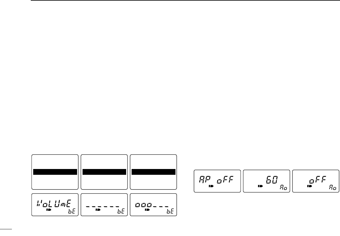
■Beep tones
The volume level for confirmation beep tones, which sound
each time a switch is pushed, can be adjusted, as desired.
When “VOLUME”is selected, the beep tone volume level is
linked with the receive volume level.
qPush [FUNC] + [(MODE)SET] momentarily to enter set
mode.
•Select a non-band scope screen in advance for color LCD.
wRotate [DIAL] until “Beep Audio”or “bEEP”appears.
•“bEEP”disappears after 1 sec. and “bE”appears when color LCD
is OFF.
ePush [↔] or rotate the tuning dial while pushing [FUNC] to
set the volume level.
rPush [(MODE)SET] to exit set mode.
■Auto power-off function
The receiver can be set to automatically turn OFF after a
specified period with beep in which no switch is pushed.
120 min., 90 min., 60 min., 30 min. and OFF can be speci-
fied. The specified period is retained even when the receiver
is turned OFF by the auto power-off function. To cancel the
function, select “OFF”in step ebelow.
qPush [FUNC] + [(MODE)SET] momentarily to enter set
mode.
•Select a non-band scope screen in advance for color LCD.
wRotate [DIAL] until “A.Power OFF”or “AP oFF”appears.
•“AP oFF”disappears after 1 sec. and “Ao”appears when color
LCD is OFF.
ePush [↔] or rotate the tuning dial while pushing [FUNC] to
select the desired time or to turn the function OFF.
rPush [(MODE)SET] to exit set mode.
60 min. auto power-offAuto power off set
mode Auto power-off is
turned OFF.
Beep tone is turned
OFF (minimum).
Beep tone is turned
ON and linked with
the volume level.
Beep tone is fixed
to the set level.
Pause Scan : 10SEC
Priority : OFF
Beep Audio : VOLUME
Light : AUTO
A.Power OFF : OFF
Pause Scan : 10SEC
Priority : OFF
Beep Audio : ______
Light : AUTO
A.Power OFF : OFF
Pause Scan : 10SEC
Priority : OFF
Beep Audio : OOO___
Light : AUTO
A.Power OFF : OFF
41
13
OTHER FUNCTIONS
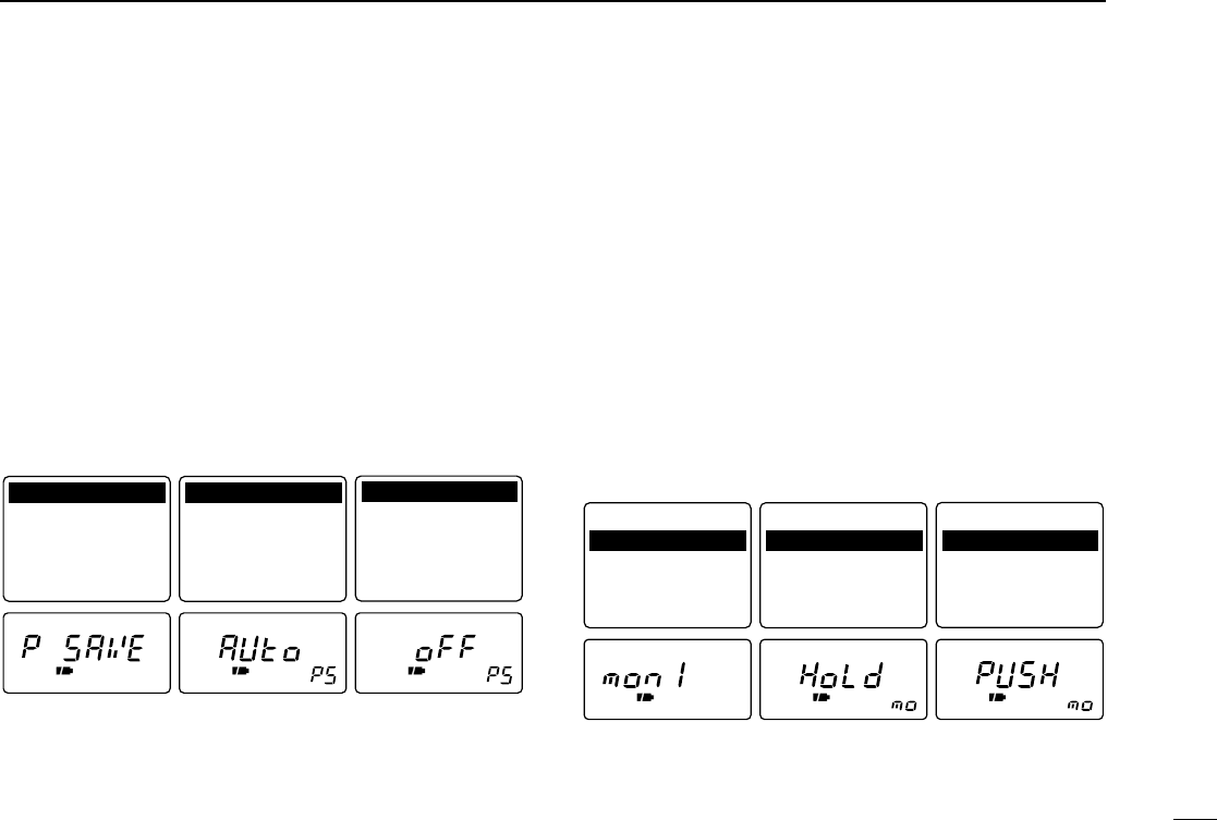
■Power saver
The power saver function reduces the current drain to con-
serve battery power.
qPush [FUNC] + [(MODE)SET] momentarily to enter set
mode.
•Select a non-band scope screen in advance for color LCD.
wRotate [DIAL] until “Power Save”or “P SAVE”appears.
•“P SAVE”disappears after 1 sec. and “PS”appears when color
LCD is OFF.
ePush [↔] or rotate the tuning dial while pushing [FUNC] to
turn the power saver ON (AUTO) or OFF.
rPush [(MODE)SET] to exit set mode.
■Monitor switch action
The monitor switch can be set as a ‘sticky’switch. When set to
the sticky condition, each push of [SQL] toggles the monitor
function on and off.
qPush [FUNC] + [(MODE)SET] momentarily to enter set
mode.
•Select a non-band scope screen in advance for color LCD.
wRotate [DIAL] until “Monitor”or “monI”appears.
•“monI”disappears after 1 sec. and “mo”appears when color LCD
is OFF.
ePush [↔] or rotate the tuning dial while pushing [FUNC] to
set the monitor switch to sticky (HOLD) or normal (PUSH).
rPush [(MODE)SET] to exit set mode.
‘Sticky’ actionMonitor switch
function set mode ‘Normal’ action
Power Save : AUTO
Monitor : PUSH
Dial Speedup: ON
Key Lock : NORMAL
Display : AUTO
Power Save : AUTO
Monitor : HOLD
Dial Speedup: ON
Key Lock : NORMAL
Display : AUTO
Power Save : AUTO
Monitor : PUSH
Dial Speedup: ON
Key Lock : NORMAL
Display : AUTO
Power saver ON
(AUTO)
Power save set
mode Power saver OFF
Power Save : AUTO
Monitor : PUSH
Dial Speedup: ON
Key Lock : NORMAL
Display : AUTO
Dial Speedup: ON
Key Lock : NORMAL
Display : AUTO
Dial Speedup: ON
Key Lock : NORMAL
Display : AUTO
Power Save : AUTO
Monitor : PUSH Power Save : OFF
Monitor : PUSH
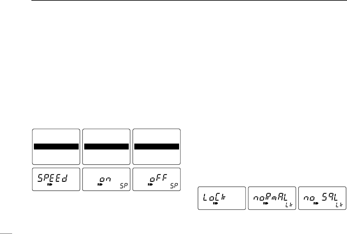
42
13 OTHER FUNCTIONS
■Dial speed acceleration
The dial speed acceleration automatically speeds up the tun-
ing dial speed when rotating the [DIAL] rapidly.
qPush [FUNC] + [(MODE)SET] momentarily to enter set
mode.
•Select a non-band scope screen in advance for color LCD.
wRotate [DIAL] until “Dial Speedup”or “SPEEd”appears.
•“SPEEd”disappears after 1 sec. and “SP”appears.
ePush [↔] or rotate the tuning dial while pushing [FUNC] to
set the dial speed acceleration ON or OFF.
rPush [(MODE)SET] to exit set mode.
■Lock function effect
The lock function prevents accidental frequency changes and
accidental function access.
While the lock function is ON, [POWER], [VOL (↕)] and [SQL]
can still be accessed. Accessible switches can be set to 1 of 4
groups in set mode.
qPush [FUNC] + [(MODE)SET] momentarily to enter set
mode.
•Select a non-band scope screen in advance for color LCD.
wRotate [DIAL] until “Key Lock”or “LoCk”appears.
•“LoCk”disappears after 1 sec. and “Lk”appears.
ePush [↔] or rotate the tuning dial while pushing [FUNC] to
select the accessible switches.
•“NORMAL”:[POWER], [VOL] and [SQL] are accessible.
•“NO SQL”:[POWER] and [SQL] are accessible.
•“NO VOL”:[POWER] and [VOL] are accessible.
•“ALL”:[POWER] is accessible.
rPush [(MODE)SET] to exit set mode.
Lock function effect
set mode [POWER], [VOL]
and [SQL] are
accessible.
[POWER] and [SQL]
are accessible.
Power Save : AUTO
Monitor : PUSH
Dial Speedup: ON
Key Lock : NORMAL
Display : AUTO
Power Save : AUTO
Key Lock : NORMAL
Display : AUTO
Power Save : AUTO
Key Lock : NORMAL
Display : AUTO
Dial speed acceleration
set mode
Dial speed
acceleration ON Dial speed
acceleration OFF
Monitor : PUSH
Dial Speedup: ON Monitor : PUSH
Dial Speedup: OFF
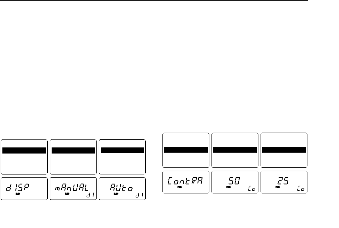
43
13
OTHER FUNCTIONS
■Display mode selection
The color LCD can be automatically turned ON when using
with the external DC power (CP-18A/E or commercially available
DC power supply; 5.5–6.3 V DC with more than 4 A capacity).
qPush [FUNC] + [(MODE)SET] momentarily to enter set
mode.
•Select a non-band scope screen in advance for color LCD.
wRotate [DIAL] until “Display”or “dISP”appears.
•“dISP”disappears after 1 sec. and “dI”appears.
ePush [↔] or rotate the tuning dial while pushing [FUNC] to
set the color LCD mode to automatic (AUTO) or manual.
•The color LCD will be turned OFF after setting.
rPush [(MODE)SET] to exit set mode.
■Display contrast
This item adjusts the contrast of the color LCD from 0 % to
100 % in 32 steps.
qPush [FUNC] + [↕] for 2 sec. to turn the color LCD ON.
wPush [FUNC] + [(MODE)SET] momentarily to enter set
mode.
•Select a non-band scope screen in advance.
eRotate [DIAL] until “Contrast”or “ContRA”appears.
•“ContRA”disappears after 1 sec. and “co”appears.
rPush [↔] or rotate the tuning dial while pushing [FUNC] to
adjust the contrast of the color LCD.
tPush [(MODE)SET] to exit set mode.
RX RX RX
50% (default)Display contrast set
mode 25%
Key Lock : NORMAL
Display : AUTO
Contrast : 50%
Bright : 50%
Back Color : 4
Key Lock : NORMAL
Bright : 50%
Back Color : 4
Key Lock : NORMAL
Bright : 50%
Back Color : 4
Display : AUTO
Contrast : 50% Display : AUTO
Contrast : 25%
Manual selection
Display mode set
mode Automatic selection
Key Lock : NORMAL
Display : AUTO
Contrast : 50%
Bright : 50%
Back Color : 4
Key Lock : NORMAL
Display : MANUAL
Contrast : 50%
Bright : 50%
Back Color : 4
Key Lock : NORMAL
Display : AUTO
Contrast : 50%
Bright : 50%
Back Color : 4
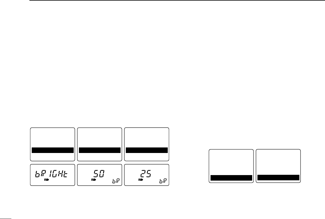
44
13 OTHER FUNCTIONS
■Display brightness
This item adjusts the brightness of the color LCD from 0 % to
100 % in 32 steps.
qPush [FUNC] + [↕] for 2 sec. to turn the color LCD ON.
wPush [FUNC] + [(MODE)SET] momentarily to enter set
mode.
•Select a non-band scope screen in advance.
eRotate [DIAL] until “Bright”appears.
•“bRIGHt”disappears after 1 sec. and “bR”appears.
rPush [↔] or rotate the tuning dial while pushing [FUNC] to
adjust the brightness of the color LCD.
tPush [(MODE)SET] to exit set mode.
■Display background color
This item selects the background color of the color LCD from
8 colors.
qPush [FUNC] + [↕] for 2 sec. to turn the color LCD ON.
wPush [FUNC] + [(MODE)SET] momentarily to enter set
mode.
•Select a non-band scope screen in advance.
eRotate [DIAL] until “Back Color”appears.
rPush [↔] or rotate the tuning dial while pushing [FUNC] to
select the background color.
•0 black 4 blue
1 pink 5 purple
2 green 6 lime
3 orange 7 white
tPush [(MODE)SET] to exit set mode.
4 (default) 1 (black)
Key Lock : NORMAL
Bright : 50%
Key Lock : NORMAL
Bright : 50%
Display : AUTO Display : AUTO
Contrast : 50%
Back Color : 4
Contrast : 50%
Back Color : 1
RX RX RX
50% (default)Display brightness
set mode 25%
Key Lock : NORMAL
Display : AUTO
Contrast : 50%
Bright : 50%
Back Color : 4
Key Lock : NORMAL
Back Color : 4
Key Lock : NORMAL
Back Color : 4
Display : AUTO Display : AUTO
Contrast : 50%
Bright : 50% Contrast : 50%
Bright : 25%
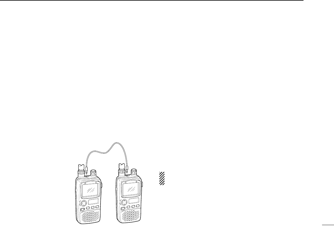
45
13
OTHER FUNCTIONS
■Cloning function
The IC-R3 has receiver-to-receiver data cloning capability.
This function is useful when you want to copy all of the pro-
grammed contents from one IC-R3 to another. An optional
OPC-474 CLONING CABLE is required.
The optional CS-R3 CLONING SOFTWARE and the optional
OPC-478 CLONING CABLE are available to clone and edit
contents with a PC (for Microsoft®Windows®95 and 98).
qWhile pushing [MODE] and ó[UP], push [POWER] for 2
sec. to enter cloning mode.
•“CLonE”appears.
wConnect an optional OPC-474 between both [SP] jacks.
ePush [SQL] on the “mas-
ter”receiver (receiver-to-
receiver cloning only).
•“oUt”appears and the signal
indicator shows that cloning
is taking place.
rPush [POWER] for 2 sec.
to turn power OFF.
Microsoft®and Windows®are regis-
tered trademarks of Microsoft Corpo-
ration in the U.S.A and other
countries.
■Partial reset
If you want to initialize the operating conditions (VFO fre-
quency, VFO settings, set mode contents) without clearing the
memory contents, a partial resetting function is available for
the receiver.
➥While pushing [FUNC] and [V/M], turn power ON to par-
tially reset the receiver.
■Total reset
Reset the CPU before operating the receiver for the first time,
or when the internal CPU malfunctions.
➥While pushing [FUNC], [V/M] and [MODE], turn power ON
to reset the CPU.
•“CLEAR”appears in the sub LCD when resetting the CPU.
CAUTION: Resetting the CPU returns all programmed
contents to their default settings.
OPC-474
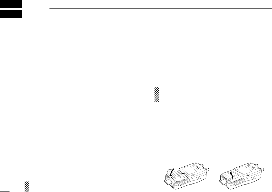
■Battery cautions
NEVER incinerate used battery packs. Internal battery gas
may cause an explosion.
NEVER immerse the battery pack in water. If the battery pack
becomes wet, be sure to wipe it dry BEFORE attaching it to
the receiver.
NEVER short terminals of the battery pack. Also, current may
flow into nearby metal objects so be careful when placing bat-
tery packs in handbags, etc.
If your battery pack seems to have no capacity even after
being charged, completely discharge it by leaving the power
ON overnight. Then, fully charge the battery pack again. If the
battery pack still does not retain a charge (or very little), a
new battery pack must be purchased.
Use Icom battery packs, chargers or cables only. The use of
non-Icom products may impair receiver performance and in-
validate the warranty.
■Battery charging
Prior to using the receiver for the first time, the battery pack
must be fully charged for optimum life and operation.
CAUTION: To avoid damage to the receiver, turn it OFF
while charging.
•Recommended temperature range for charging:
0°C to +35°C; +32°F to +95°F
•Use the wall charger (BC-136A/D*) or optional desktop
charger (BC-135 for rapid charging) only. NEVER use an-
other manufactures’charger.
*Not supplied with some versions.
•An optional cable CP-18A/E (for 12 V cigarette lighter
socket) can be used in-stead of the AC adapters of the
above chargers.
CAUTION:
BE SURE to remove the CP-18A/E when charg-
ing is finished, because, a slight current still follows in the
CP-18A/E and the vehicle’s battery will become exhausted.
◊Battery pack installation
qRemove the battery cover from the receiver.
wRemove the supplied battery spacer for alkaline battery
use.
eInstall the Li-Ion battery pack (BP-206).
•Be sure to observe the correct direction.
•Charge Li-Ion battery pack before use.
•Battery pack installation •Battery pack removal
14 BATTERY CHARGING
46
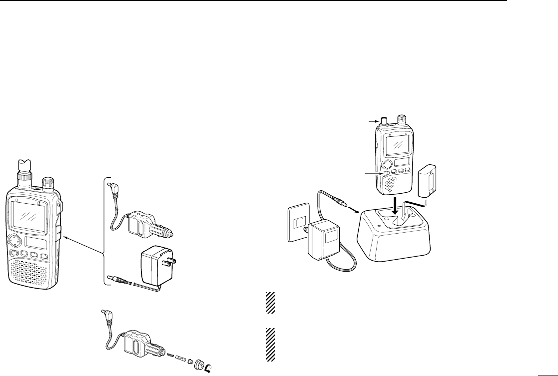
47
14
BATTERY CHARGING
◊Regular charging
qAttach the battery pack to the receiver.
wBe sure to turn the receiver power OFF.
eConnect the AC adapter (BC-136A/D*) or optional cable
(CP-18A/E) as shown below.
*Not supplied with some versions.
rRemove any cables from the [DC 6V] jack.
•Charging periods: 15 hours (w/BP-206)
◊CP-18A/E fuse
replacement
◊Rapid charging with the BC-135
The optional BC-135 provides rapid charging of battery
packs.
•Charging periods: 2.5 hours (w/BP-206)
CAUTION: Shorten or remove the telescoping antenna be-
fore charging to prevent the receiver from overturning.
If the charge indicator flashes orange, there may be a
problem with the battery pack (or charger). Re-insert the
battery pack or contact your dealer.
Turn power OFF.
BC-135
Check the
orientation.
Shorten or remove
the antenna.
IC-R3 with
BP-206
BC-136A/D
CP-18A/E
(optional)
BE SURE to remove CP-18A/E
when charging is finished.
To
[DC 6V]
CP-18A/E
Fuse 5 A
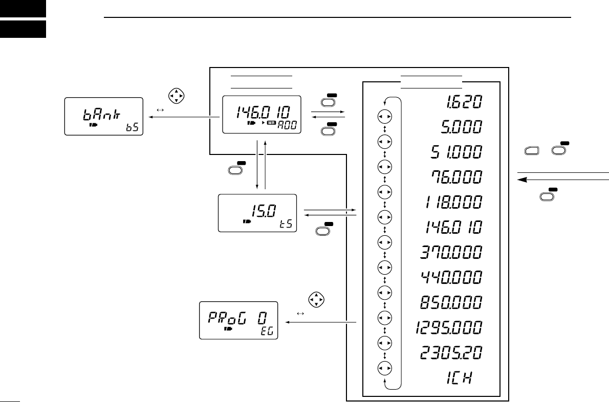
48
15 OPERATION FLOW CHART
MODE SET
V/M SKIP
V/M SKIP
FM
P
MODE SET
MODE SET
momentarily
momentarily
MODE SET
FUNC +
VFO mode
Memory mode
Program scan starting
menu (p. 19)
Bank scan starting menu
(p. 20)
Tuning step set mode
(p. 8)
() for 2 sec.
for 2 sec.
for 2 sec.
() for 2 sec.
0.495–1.620 MHz
1.625–29.995 MHz
30.0–75.995 MHz
76.0–107.995 MHz
136.0–255.095 MHz
108.0–135.995 MHz
255.1–382.095 MHz
382.1–769.795 MHz
769.8–960.095 MHz
960.1–1399.995 MHz
1400.0–2450.095 MHz
TV channels
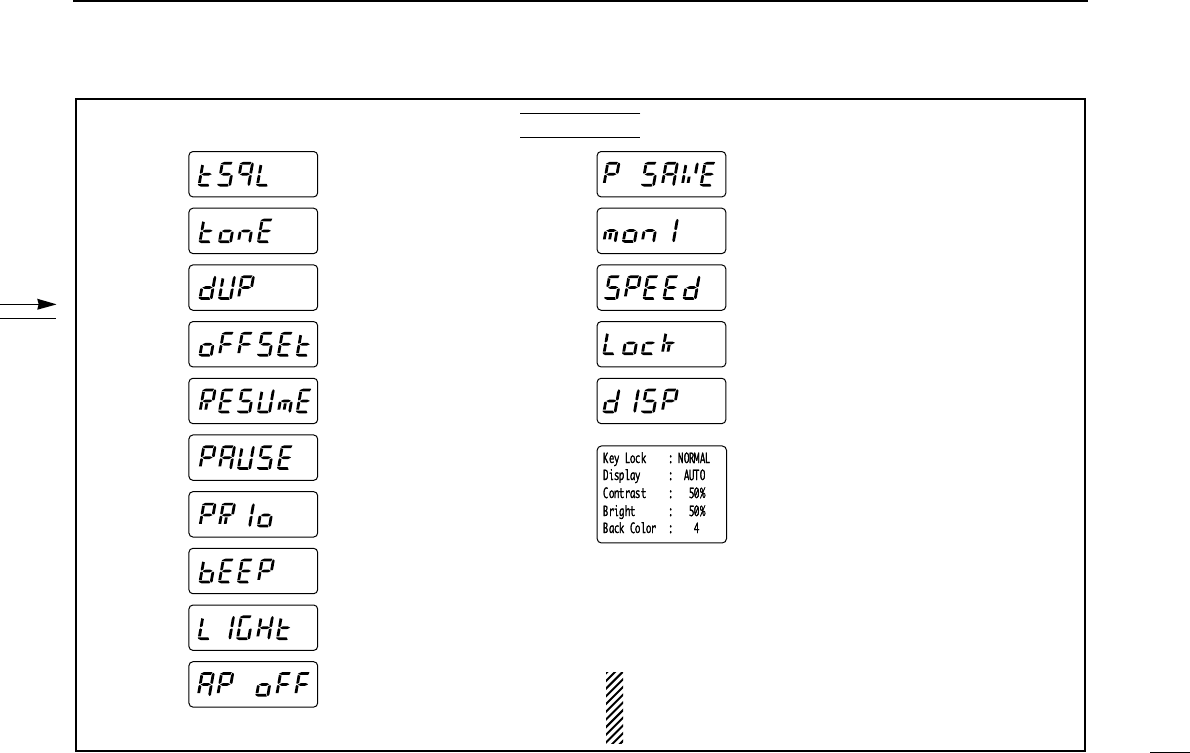
49
15
OPERATION FLOW CHART
Tone squelch (p. 28)
Tone squelch tone
frequency (p. 28)
B Duplex direction (p. 31)
B Offset frequency (p. 32)
Scan resume time (p. 23)
Scan pause time (p. 22)
Priority watch (p. 26)
Confirmation beep (p. 40)
Backlighting (p. 13)
Auto power OFF (p. 40)
Power save (p. 41)
Monitor switch action
(p. 41)
Dial speed (p. 42)
Lock function effect (p. 42)
Color LCD function (p. 43)
Color LCD contrast (p. 43)
Color LCD brightness
(p. 44)
L Color LCD background
color (p. 44)
Set mode
B: Does not appear within the broadcast band (0.495 – 1.620 MHz).
L: Appears when the color LCD is ON.
Displays for set modes show the default settings.
Push [↔] or rotate the tuning dial while pushing [FUNC] to
change the set mode condition.

The following tables show the channels versus video and
audio frequencies depending on each version.
■U.S.A. channels ■CCIR channels
50
16 TV FREQUENCY TABLE
CH Video Audio
2 55.25 59.75
3 61.25 65.75
4 67.25 71.75
5 77.25 81.75
6 83.25 87.75
7 175.25 179.75
8 181.25 185.75
9 187.25 191.75
10 193.25 197.75
11 199.25 203.75
12 205.25 209.75
13 211.25 215.75
14 471.25 475.75
15 477.25 481.75
16 483.25 487.75
17 489.25 493.75
18 495.25 499.75
19 501.25 505.75
20 507.25 511.75
21 513.25 517.75
22 519.25 523.75
23 525.25 529.75
24 531.25 535.75
25 537.25 541.75
CH Video Audio
26 543.25 547.75
27 549.25 553.75
28 555.25 559.75
29 561.25 565.75
30 567.25 571.75
31 573.25 577.75
32 579.25 583.75
33 585.25 589.75
34 591.25 595.75
35 597.25 601.75
36 603.25 607.75
37 609.25 613.75
38 615.25 619.75
39 621.25 625.75
40 627.25 631.75
41 633.25 637.75
42 639.25 643.75
43 645.25 649.75
44 651.25 655.75
45 657.25 661.75
46 663.25 667.75
47 669.25 673.75
48 675.25 679.75
49 681.25 685.75
CH Video Audio
50 687.25 691.75
51 693.25 697.75
52 699.25 703.75
53 705.25 709.75
54 711.25 715.75
55 717.25 721.75
56 723.25 727.75
57 729.25 733.75
58 735.25 739.75
59 741.25 745.75
60 747.25 751.75
61 753.25 757.75
62 759.25 763.75
63 765.25 769.75
64 771.25 775.75
65 777.25 781.75
66 783.25 787.75
67 789.25 793.75
68 795.25 799.75
69 801.25 805.75
CH Video Audio
1 41.25 46.75
2 48.25 53.75
3 55.25 60.75
4 62.25 67.75
5 175.25 180.75
6 182.25 187.75
7 189.25 194.75
8 196.25 201.75
9 203.25 208.75
10 210.25 215.75
11 217.25 222.75
12 224.25 229.75
21 471.25 476.75
22 479.25 484.75
23 487.25 492.75
24 495.25 500.75
25 503.25 508.75
26 511.25 516.75
27 519.25 524.75
28 527.25 532.75
29 535.25 540.75
30 543.25 548.75
CH Video Audio
31 551.25 556.75
32 559.25 564.75
33 567.25 572.75
34 575.25 580.75
35 583.25 588.75
36 591.25 596.75
37 599.25 604.75
38 607.25 612.75
39 615.25 620.75
40 623.25 628.75
41 631.25 636.75
42 639.25 644.75
43 647.25 652.75
44 655.25 660.75
45 663.25 668.75
46 671.25 676.75
47 679.25 684.75
48 687.25 692.75
49 695.25 700.75
50 703.25 708.75
51 711.25 716.75
52 719.25 724.75

■Australian channels
CH Video Audio
39 604.25 609.75
40 611.25 616.75
41 618.25 623.75
42 625.25 630.75
43 632.25 637.75
44 639.25 644.75
45 646.25 651.75
46 653.25 658.75
47 660.25 665.75
48 667.25 672.75
49 674.25 679.75
50 681.25 686.75
51 688.25 693.75
52 695.25 700.75
53 702.25 707.75
54 709.25 714.75
55 716.25 721.75
56 723.25 728.75
57 730.25 735.75
58 737.25 742.75
59 744.25 749.75
60 751.25 756.75
61 758.25 763.75
62 765.25 770.75
CH Video Audio
0* 46.25 51.75
1 57.25 62.75
2 64.25 69.75
3 86.25 91.75
4 95.25 100.75
5 102.25 107.75
5A* 138.25 143.75
6 175.25 180.75
7 182.25 187.75
8 189.25 194.75
9 196.25 201.75
10 209.25 214.75
11 216.25 221.75
28 527.25 532.75
29 534.25 539.75
30 541.25 546.75
31 548.25 553.75
32 555.25 560.75
33 562.25 567.75
34 569.25 574.75
35 576.25 581.75
36 583.25 588.75
37 590.25 595.75
38 597.25 602.75
■New Zealand
channels
CH Video Audio
1 45.25 50.75
2 55.25 60.75
3 62.25 67.75
4 175.25 180.75
5 182.25 187.75
6 189.25 194.75
7 196.25 201.75
8 203.25 208.75
9 210.25 215.75
10 217.25 222.75
11 224.25 229.75
■Taiwan channels
CH Video Audio
7 175.25 179.75
8 181.25 185.75
9 187.25 191.75
10 193.25 197.75
11 199.25 203.75
12 205.25 209.75
51
16
TV FREQUENCY TABLE
CH Video Audio
53 727.25 732.75
54 735.25 740.75
55 743.25 748.75
56 751.25 756.75
57 759.25 764.75
58 767.25 772.75
59 775.25 780.75
60 783.25 788.75
61 791.25 796.75
62 799.25 804.75
63 807.25 812.75
64 815.25 820.75
65 823.25 828.75
66 831.25 836.75
67 839.25 844.75
68 847.25 852.75
69 855.25 860.75
CH Video Audio
63 772.25 777.75
64 779.25 784.75
65 786.25 791.75
66 793.25 798.75
67 800.25 805.75
68 807.25 812.75
NOTE:
*In the case of the IC-R3,
‘0’and ‘5A’channels are
displayed as ‘12’and ‘13,’
respectively.

52
16 TV FREQUENCY TABLE
■China channels
CH Video Audio
1 49.75 56.25
2 57.75 64.25
3 65.75 72.25
4 77.25 83.75
5 85.25 91.75
6 168.25 174.75
7 176.25 182.75
8 184.25 190.75
9 192.25 198.75
10 200.25 206.75
11 208.25 214.75
12 216.25 222.75
13 471.25 477.75
14 479.25 485.75
15 487.25 493.75
16 495.25 501.75
17 503.25 509.75
18 511.25 517.75
19 519.25 525.75
20 527.25 533.75
21 535.25 541.75
22 543.25 549.75
23 551.25 557.75
24 559.25 565.75
25 607.25 613.75
26 615.25 621.75
27 623.25 629.75
CH Video Audio
28 631.25 637.75
29 639.25 645.75
30 647.25 653.75
31 655.25 661.75
32 663.25 669.75
33 671.25 677.75
34 679.25 685.75
35 687.25 693.75
36 695.25 701.75
37 703.25 709.75
38 711.25 717.75
39 719.25 725.75
40 727.25 733.75
41 735.25 741.75
42 743.25 749.75
43 751.25 757.75
44 759.25 765.75
45 767.25 773.75
46 775.25 781.75
47 783.25 789.75
48 791.25 797.75
49 799.25 805.75
50 807.25 813.75
51 815.25 821.75
52 823.25 829.75
53 831.25 837.75
54 839.25 845.75
CH Video Audio
55 847.25 853.75
56 855.25 861.75
57 863.25 869.75
58 871.25 877.75
59 879.25 885.75
60 887.25 893.75
61 895.25 901.75
62 903.25 909.75
63 911.25 917.75
64 919.25 925.75
65 927.25 933.75
66 935.25 941.75
67 943.25 949.75
68 951.25 957.75
■Indonesian channels
CH Video Audio
2 48.25 53.75
3 55.25 60.75
4 62.25 67.75
5 175.25 180.75
6 182.25 187.75
7 189.25 194.75
8 196.25 201.75
9 203.25 208.75
10 210.25 215.75
11 217.25 222.75
12 224.25 229.75
21 471.25 476.75
22 479.25 484.75
23 487.25 492.75
24 495.25 500.75
25 503.25 508.75
26 511.25 516.75
27 519.25 524.75
28 527.25 532.75
29 535.25 540.75
30 543.25 548.75
31 551.25 556.75
32 559.25 564.75
33 567.25 572.75
34 575.25 580.75
35 583.25 588.75
36 591.25 596.75
CH Video Audio
37 599.25 604.75
38 607.25 612.75
39 615.25 620.75
40 623.25 628.75
41 631.25 636.75
42 639.25 644.75
43 647.25 652.75
44 655.25 660.75
45 663.25 668.75
46 671.25 676.75
47 679.25 684.75
48 687.25 692.75
49 695.25 700.75
50 703.25 708.75
51 711.25 716.75
52 719.25 724.75
53 727.25 732.75
54 735.25 740.75
55 743.25 748.75
56 751.25 756.75
57 759.25 764.75
58 767.25 772.75
59 775.25 780.75
60 783.25 788.75
61 791.25 796.75
62 799.25 804.75
63 807.25 812.75

53
16
TV FREQUENCY TABLE
■FOT channels
CH Video Audio
4 175.25 181.75
5 183.25 189.75
6 191.25 197.75
7 199.25 205.75
8 207.25 213.75
9 215.25 221.75
CH Video Audio
64 815.25 820.75
65 823.25 828.75
66 831.25 836.75
67 839.25 844.75
68 847.25 852.75
69 855.25 860.75
■Italian channels
CH Video Audio
A* 53.75 59.25
B* 62.25 67.75
C* 82.25 87.75
D* 175.25 180.75
E* 183.25 188.75
F* 192.25 197.75
G* 201.25 206.75
H* 210.25 215.75
H1* 217.25 222.75
H2* 224.25 229.75
21 471.25 476.75
22 479.25 484.75
23 487.25 492.75
24 495.25 500.75
25 503.25 508.75
26 511.25 516.75
27 519.25 524.75
28 527.25 532.75
29 535.25 540.75
30 543.25 548.75
31 551.25 556.75
32 559.25 564.75
33 567.25 572.75
34 575.25 580.75
35 583.25 588.75
36 591.25 596.75
37 599.25 604.75
CH Video Audio
38 607.25 612.75
39 615.25 620.75
40 623.25 628.75
41 631.25 636.75
42 639.25 644.75
43 647.25 652.75
44 655.25 660.75
45 663.25 668.75
46 671.25 676.75
47 679.25 684.75
48 687.25 692.75
49 695.25 700.75
50 703.25 708.75
51 711.25 716.75
52 719.25 724.75
53 727.25 732.75
54 735.25 740.75
55 743.25 748.75
56 751.25 756.75
57 759.25 764.75
58 767.25 772.75
59 775.25 780.75
60 783.25 788.75
61 791.25 796.75
62 799.25 804.75
63 807.25 812.75
64 815.25 820.75
CH Video Audio
65 823.25 828.75
66 831.25 836.75
67 839.25 844.75
68 847.25 852.75
69 855.25 860.75
NOTE:
*In the case of the IC-R3,
‘A’–‘H,’‘H1’and ‘H2’chan-
nels are displayed as
‘1’–‘8,’‘9’and ‘10,’respec-
tively.
54
17 SPECIFICATIONS AND OPTIONS
◊General
•Frequency coverage : (unit: MHz)
U.S.A. version 0.495–815.995,
902–2450.095
Non-U.S.A. versions 0.495–2450.095
•Mode : FM, AM, WFM, AM-TV,*1
FM-TV,*2
*1One of either NTSC M, PAL B or PAL G systems.
*2For 900–1300 MHz and 2250–2450 MHz ranges only; not
available in some versions.
•No. of memory channels : 450 (50 channel ×8 banks plus
50 scan edges)
•Usable temp. range : –10°C to +60°C;
+14°F to +140°F
•Tuning steps : 5, 6.25, 9,*310, 12.5, 15, 20,
25, 30, 50 and 100 kHz
*3Fixed tuning step while 0.495–1.620 MHz is selected except
for U.S.A. and Canada versions.
•Frequency stability : ±6 ppm max. (–10°C to +50°C)
•Power supply requirement : 3.6–6.3 V DC
(negative ground)
•Current drain (at 4.5 V DC) :
At rated output 210 mA typical (backlight OFF)
At stand-by 140 mA typical
Power save 53 mA typical
TV reception 730 mA typical (color LCD ON)
•Antenna connector : BNC (50 Ω)
•Dimensions : 61(W)×120(H)×32.9(D) mm;
(projections not included) 213⁄32(W)×423⁄32(H)×19⁄32(D) in
•Weight : 300 g; 10.6 oz
(w/antenna and battery)
◊Receiver
•Receive system : Triple-conversion*4
superheterodyne
*4below 1150 MHz; Quadruple-conversion for above 1150 MHz
•Intermediate frequencies :
*530–799.995, 1321–2099.995 MHz range
*6800–1320.995, 2100–2450.095 MHz range
•Sensitivity (except spurious points; typical):
FM 1.625–4.995 MHz 0.32 µV
(at 12 dB SINAD) 5.0–469.995 MHz 0.25 µV
470–799.995 MHz 0.45 µV
800–1999.995 MHz 0.56 µV
2000–2299.995 MHz 1.0 µV
2300–2450.095 MHz 1.8 µV
WFM 76–107.995 MHz 1.0 µV
(at 12 dB SINAD) 175–221.995 MHz 1.0 µV
470–769.995 MHz 1.8 µV
AM, FM
1st 240.1 240.1 241.85*5238.35*6
26.05 13.25 45.75 38.90
0.450 0.450 –
2nd
3rd
WFM TV
U.S.A. Europe

55
17
SPECIFICATIONS AND OPTIONS
AM (at 10 dB S/N) 0.495–4.995 MHz 1.4 µV
5.0–29.995 MHz 1.0 µV
118–136.000 MHz 0.79 µV
222–329.995 MHz 1.0 µV
•Selectivity :
FM, AM More than 12 kHz/–6 dB
Less than 30 kHz/–50 dB
WFM More than 150 kHz/–6 dB
•Audio output power : 100 mW typical at 10%
(at 4.5 V DC) distortion with an 8 Ωload
•SP connector : 3-conductor 3.5 (d) mm
(1⁄8˝)/8 Ω
•Audio/Video connector : 3-conductor 3.5 (d) mm (1⁄8˝)
◊Operating periods (Approx.)
*Operating periods depend on batteries used.
◊Options
BC-135 DESKTOP CHARGER
Used for rapid charging of Li-Ion battery pack. Charging time:
2.5 hours. An AC adapter is supplied with the charger.
BC-136A/D BATTERY CHARGER
Regularly charges a Li-Ion battery pack.
BP-206 Li-Ion BATTERY PACK
3.7 V/1650 mAh Lithium Ion battery pack. Same as supplied
one.
CP-18A/E CIGARETTE LIGHTER CABLE
Allows you to operate the receiver through a 12 V cigarette
lighter socket, and also charges a Li-Ion battery pack regu-
larly. A DC-DC converter is built-in.
LC-151 CARRYING CASE
Helps protect the receiver from scratches, etc.
SP-13 EARPHONE
Provides clear receive audio in noisy environments.
CS-R3 CLONING SOFTWARE + OPC-478 CLONING
CABLE
Allows you to transfer data from memories, etc. and quickly
and easily edit and store data via a PC (for Microsoft®Win-
dows®95 and 98).
OPC-474 CLONING CABLE
Used for receiver-to-receiver cloning.
TV reception
color LCD ON Rated output
backlight OFF Power save
BP-206 1 hr. 45 min.
45 min.
50 min.
2 hrs. 10 min.
57 min.
60 min.
25 hrs. 30 min.
27 hrs. 30 min.
12 hrs. 50 min.
Alkaline batteries*
Ni-Cd batteries*
All stated specifications are subject to change without
notice or obligation.
Microsoft®and Windows®are registered trademarks of Microsoft Corporation
in the U.S.A and other countries.

56
18 TROUBLESHOOTING
PROBLEM POSSIBLE CAUSE SOLUTION REF.
No power comes ON. •The batteries are exhausted.
•The battery polarity is reversed.
•Replace the batteries or charge the battery pack.
•Check the battery polarity.
pgs. 1,
46
p. 1
No sound comes from the
speaker.
•Volume level is too low.
•The squelch level is set too tight.
•Different tone is selected with tone squelch.
•Push ó[UP] to obtain a suitable level.
•Open the squelch.
•Check the tone using tone scan.
p. 11
p. 11
p. 30
Frequency cannot be set. •The lock function is activated. •Push [FUNC] + [MODE(SET)] for 2 sec. to cancel the
function.
p. 9
No beeps sound. •Beep tones are turned OFF or the beep tone
level is low.
•Turn beep tones ON or set the beep tone level to
appropriate level in set mode.
p. 40
Receive audio is
distorted.
•The operating mode is not selected correctly. •Push [MODE] to select a suitable operating mode. p. 12
Desired set mode item
cannot be selected.
•Some set mode items can be selected only
when the color LCD is ON.
•Some set mode items cannot be selected in
the broadcast band.
•Turn the color LCD ON.
•Choose a band other than the broadcast band.
pgs. 6,
38
p. 38
If your receiver seems to be malfunctioning, please check the
following points before sending it to a service center.
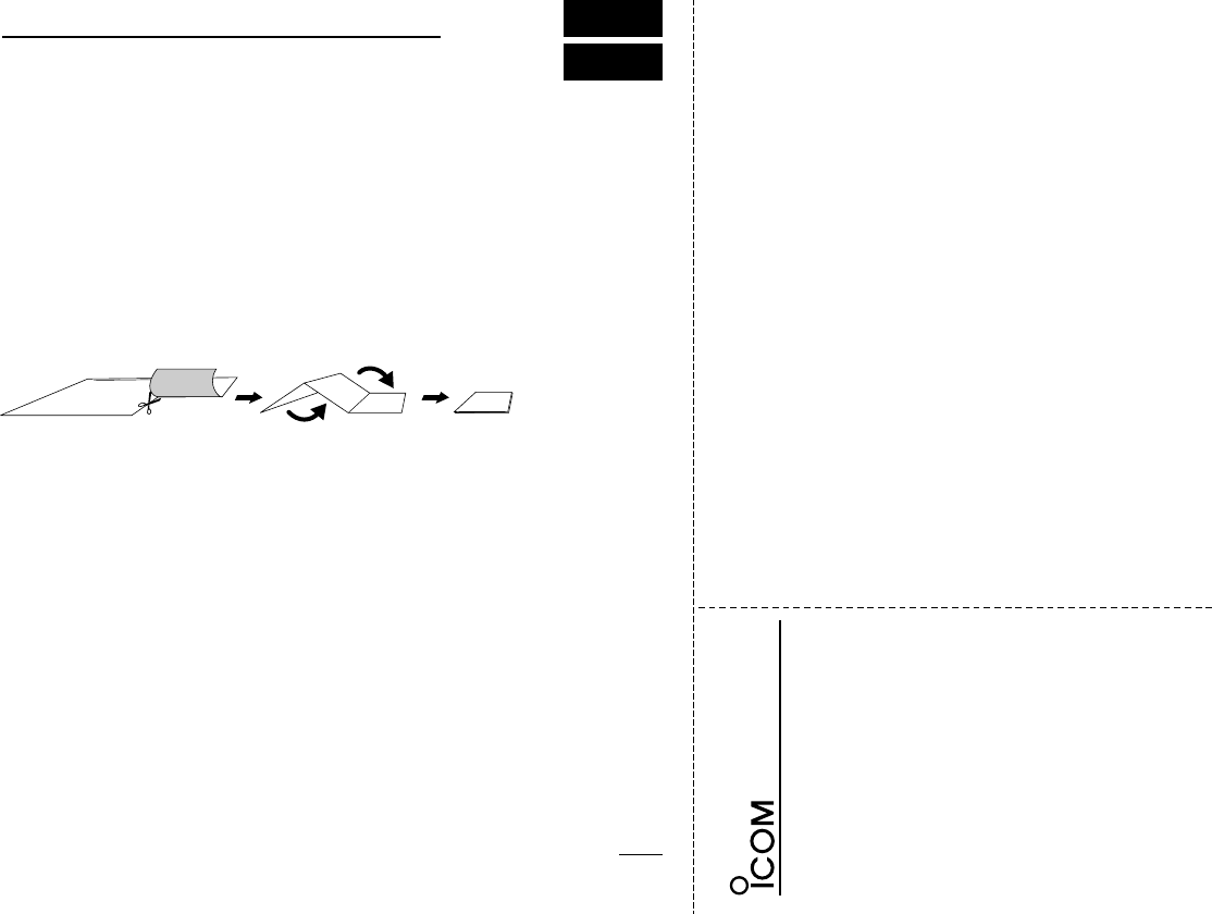
OPERATING GUIDE
iR3
■BASIC OPERATION
qPush [POWER] for 2 sec.
wPush [↕] to set the desired audio
level.
eSelect VFO mode with [V/M].
rSelect the desired band with [↔].
tRotate [DIAL] to change the fre-
quency.
•The frequency changes according to
the preset tuning steps.
ySet the squelch level.
•While pushing [SQL], rotate [DIAL].
•The first click of [DIAL] indicates the
current squelch level.
•“LEVEL1”is loose squelch and
“LEVEL9”is tight squelch.
•“AUTO”indicates automatic level ad-
justment.
tWhen a signal is received:
•Squelch opens and audio is emitted
from the speaker.
•The S/RF indicator shows the relative
signal strength.
◊Using the dial select step (p. 39)
Rotate [DIAL] while pushing [FUNC]
to change the frequency in 100 kHz,
1 MHz or 10 MHz steps.
■DUPLEX OPERATION
qSet the receive station frequency
(e.g. repeater output frequency).
wSet the shift direction of the trans-
mit station frequency in set mode.
(–DUP or DUP)
ePush and hold [SQL] to monitor
the transmit station’s frequency.
◊Tone scan (p. 30)
Push [FUNC] + [↔] for 2 sec. to start
the tone scan.
■
MEMORY CHANNEL SELECTION
qPush [V/M] to select memory
mode.
•“M:”or “X”appears.
wSelect a memory channel with
[DIAL].
eRotate [DIAL] while pushing
[FUNC] to select the memory
bank.
■MEMORY CLEAR
qSelect the desired memory chan-
nel.
wSelect VFO mode with [V/M] and
push [V/M] for 1 sec. to indicate
the channel.
ePush [FUNC] + [V/M] for 2 sec.
Important operating instructions are summed up in this and the following page
for your simple reference.
By cutting along the line and folding on the dotted line, it will become a card
sized operating guide which can easily be carried in a card case or wallet,
etc.
q Cut w Fold e Complete
<CUT HERE>
57
19
QUICK REFERENCE

58
19 QUICK REFERENCE
■SCAN
◊Full/band/programmed scan
qSelect VFO mode with [V/M].
wMake sure the squelch is set to
the threshold point.
ePush [↔] for 2 sec. to start the
scan.
•Rotate [DIAL] while pushing [↔] to
select scan edge, if desired.
•To change the scanning direction, ro-
tate [DIAL].
rPush [↔] again to stop the scan.
◊Memory (bank) scan
qSelect memory mode with [V/M].
wMake sure the squelch is set to
the threshold point.
ePush [↔] for 2 sec. to start the
scan.
•Rotate [DIAL] while pushing [↔] to
turn memory bank scan ON or OFF,
if desired.
rPush [↔] again to stop the scan.
■SET MODE
qPush [FUNC] + [(MODE)SET]
momentarily to enter set mode.
•Select non-band scope screen in ad-
vance for color LCD.
wRotate [DIAL] to select a display.
ePush [↔] or rotate [DIAL] while
pushing [FUNC] to set the condi-
tion.
rPush [(MODE) SET] to exit set
mode.
■LOCK FUNCTION
Push [FUNC] + [(MODE)SET] for 2
sec. to toggle the lock function ON or
OFF. (p. 9)
■CPU RESETTING
◊Partial resetting (p. 45)
While pushing [FUNC] and [V/M],
turn power on to partially reset the
receiver.
•Partial resetting does not clear the mem-
ory channel contents.
◊Total resetting (p. 45)
While pushing [FUNC], [V/M] and
[MODE], turn power on to reset the
receiver.
Caution: Resetting the receiver
initializes all memory contents.

DECLARATION
OF CONFORMITY
We Icom Inc. Japan
6-9-16, Kamihigashi, Hirano-ku
Osaka 547-0002, Japan
Type-designation: iC-r3
Version (where applicable):
Kind of equipment:
COMMUNICATIONS RECEIVER
This compliances is based on conformity with the following harmonised
standards, specifications or documents:
i)
EN 60950
ii) prEN 301 489-1
iii) prEN 301 489-15
iv) prEN 301 783-2
v)
Signature
Authorized representative name
Place and date of issue
T. Aoki
General Manager
Icom (Europe) GmbH
Himmelgeister straße 100
D-40225 Düsseldorf
Düsseldorf 11. July. 2000
Icom (Europe) GmbH
Declare on our sole responsability that this equipment complies the
essential requirements of the Radio and Telecommunications Terminal
Equipment Directive, 1999/5/CE.

Count on us!
6-9-16 Kamihigashi, Hirano-ku, Osaka 547-0002 Japan
A-5653H-1EX-w
Printed in Japan
© 2000 Icom Inc.