ICOM orporated IC-R5 Scanning Receiver User Manual IC R5 Instruction Manual
ICOM Incorporated Scanning Receiver IC R5 Instruction Manual
UserManual.wiki
>
ICOM orporated
>
IC R5 User Manual
Users Manual
Navigation menu
Upload a User Manual
Namespaces
Wiki Guide
HTML
PDF
Info
Views
User Manual
Discussion / Help
Navigation
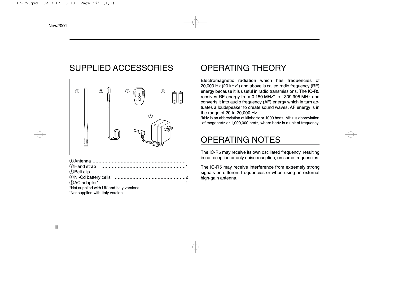
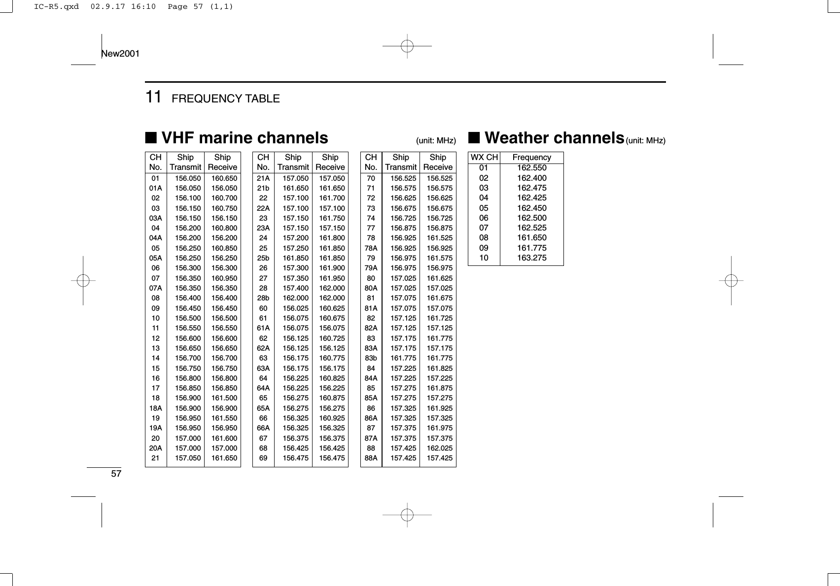
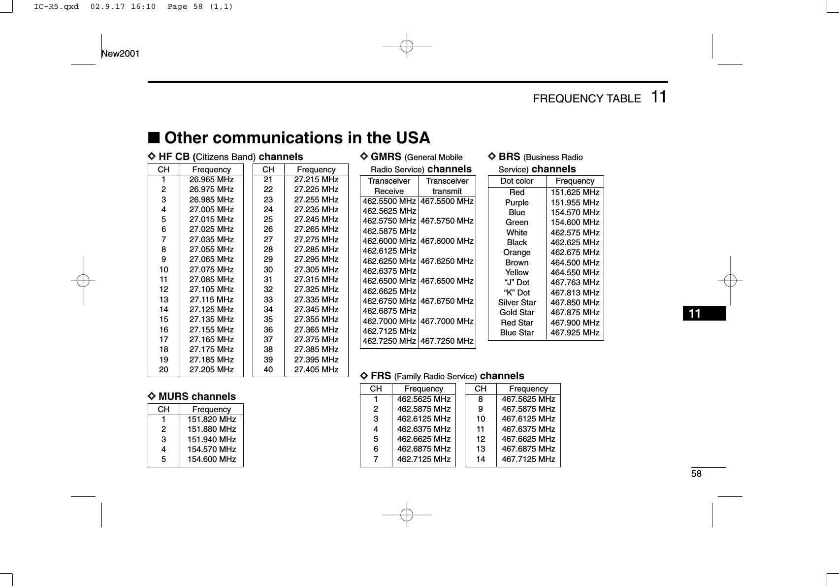
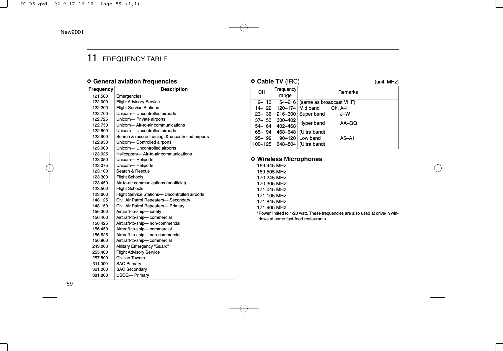
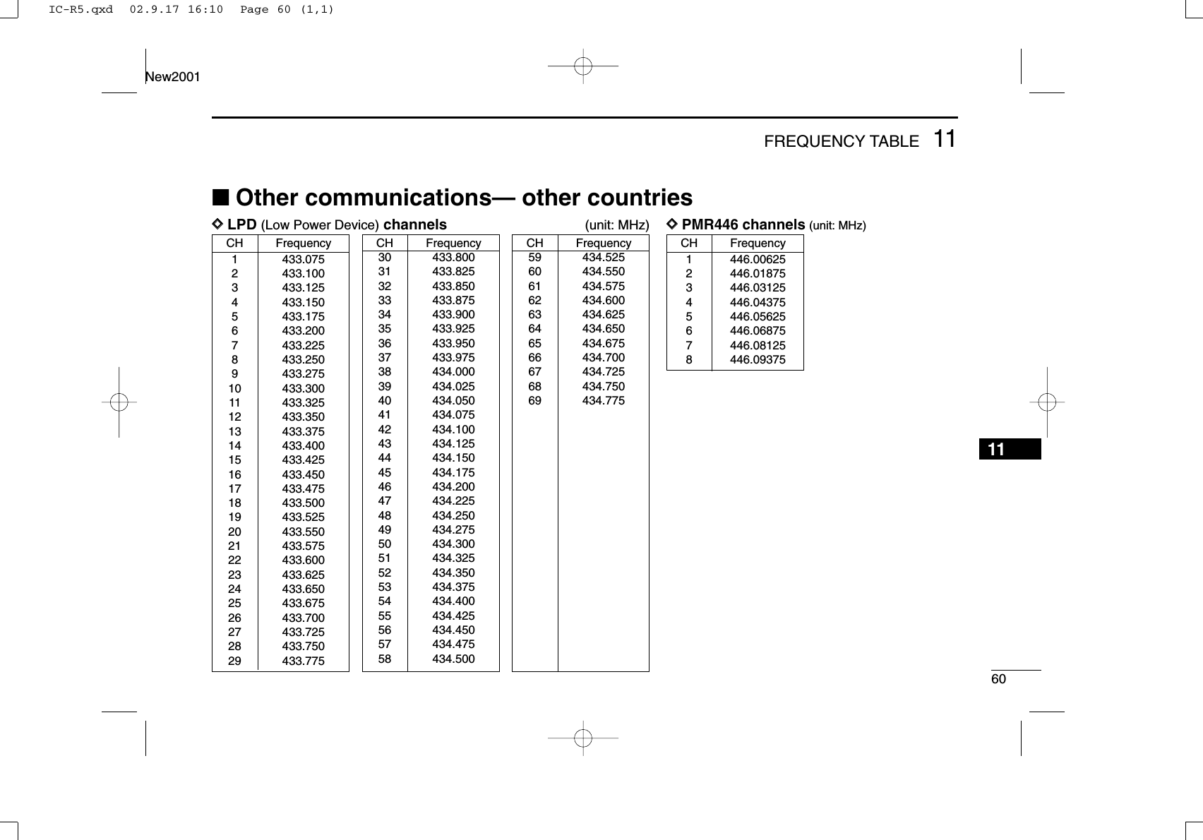
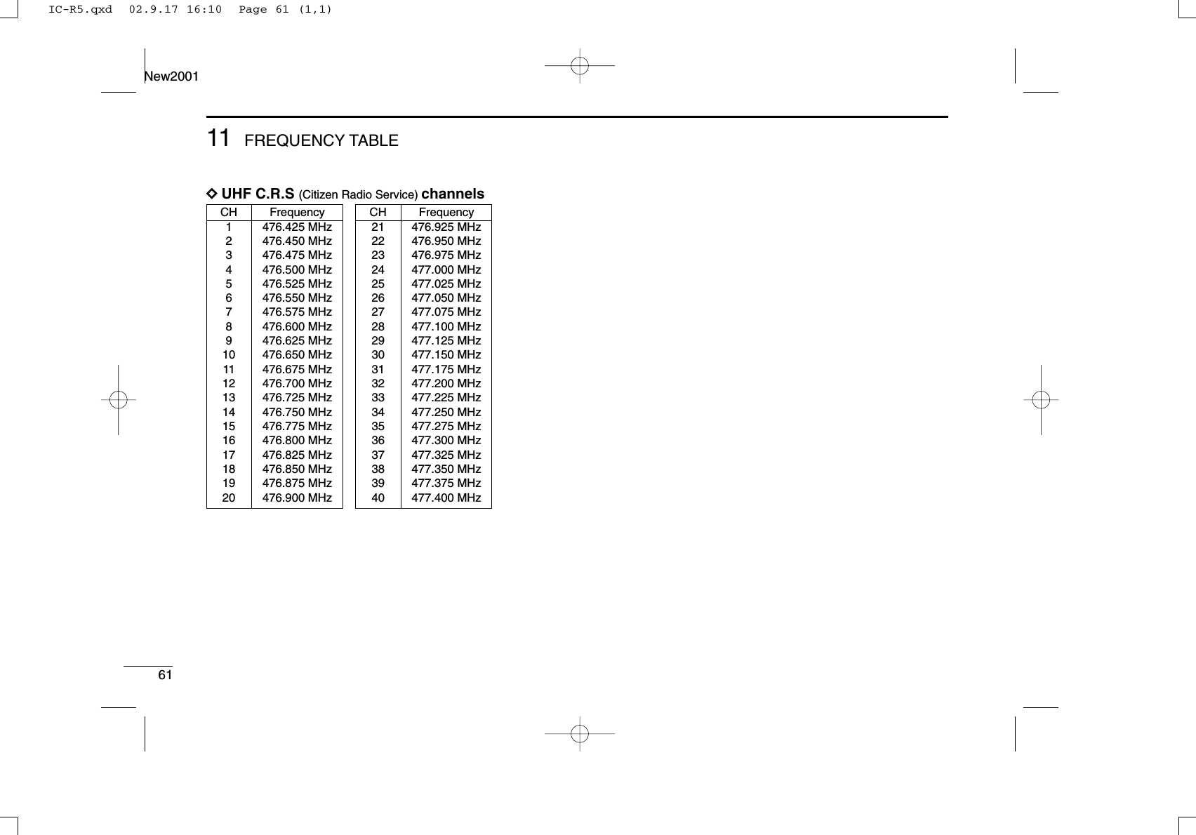
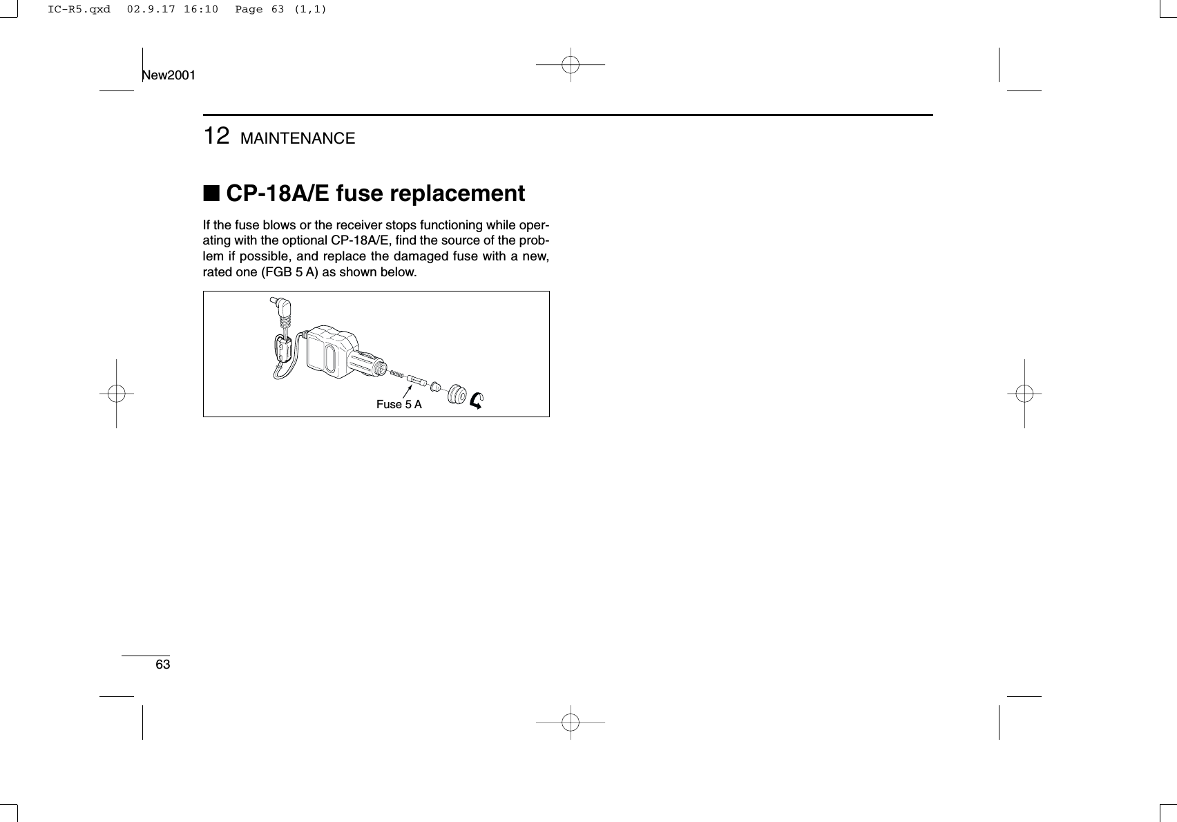
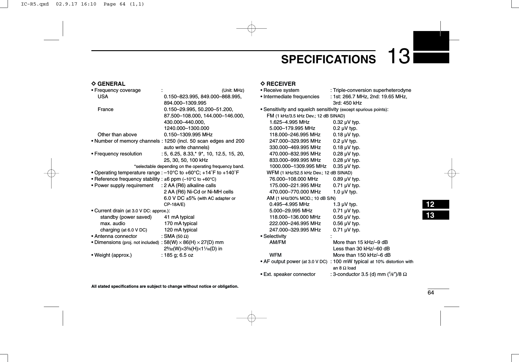
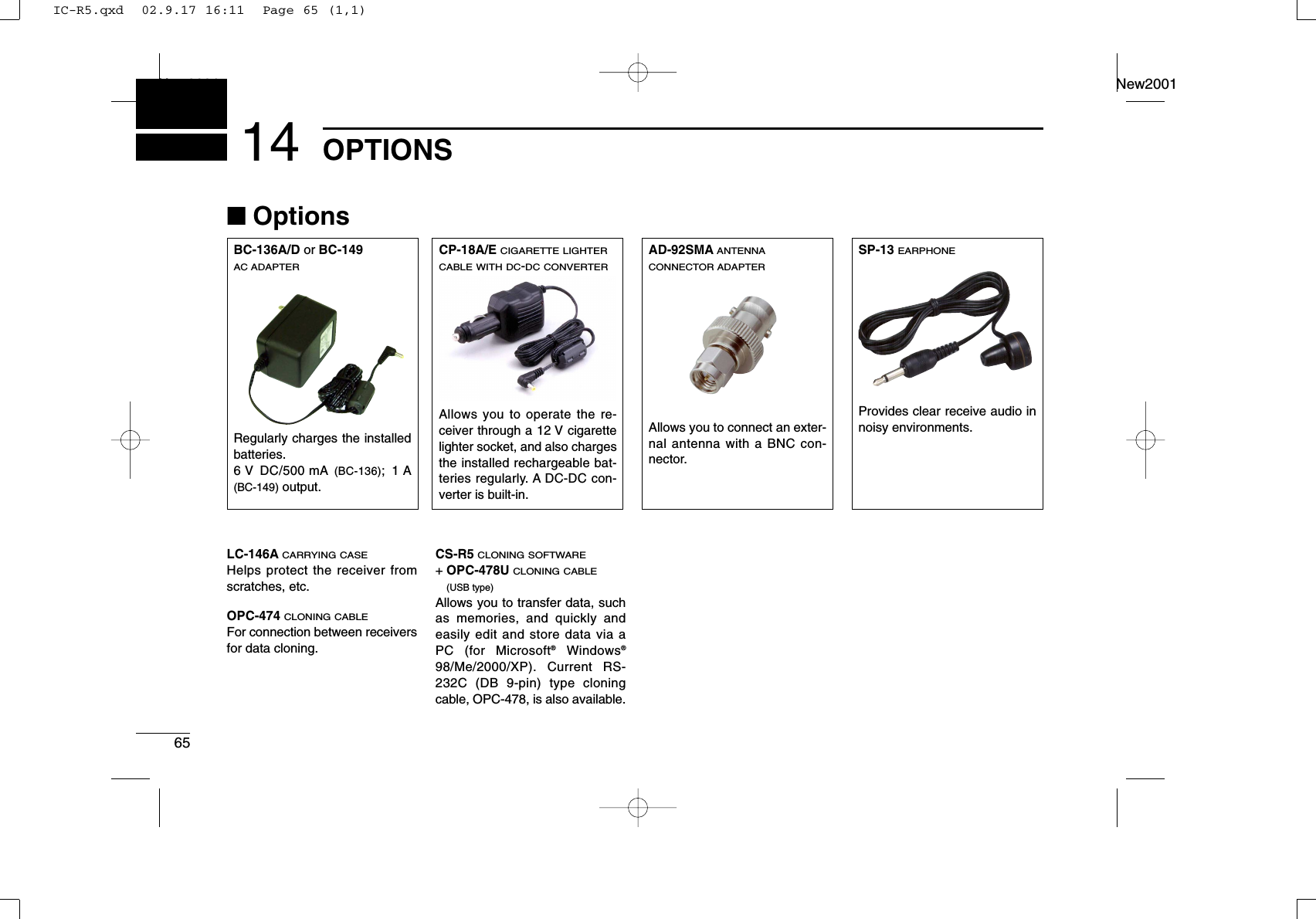
![New2001ivTABLE OF CONTENTS 123456789101112131415FOREWORD .................................................. iIMPORTANT .................................................. iEXPLICIT DEFINITIONS ................................ iPRECAUTION ............................................... iiSUPPLIED ACCESSORIES ......................... iiiOPERATING THEORY ................................. iiiOPERATING NOTES ................................... iiiTABLE OF CONTENTS ................................ ivQUICK REFERENCE GUIDE .................. I–VI■Preparation ............................................. I■Receiving a signal ................................ III■Memory programming .......................... IV■Programmed scan operation................. V1 PANEL DESCRIPTION ........................ 1–4■Front, top and side panels .................... 1■Function display .................................... 32 BATTERY CHARGING ........................ 5–6■Battery installation ................................. 5■Caution .................................................. 5■Battery charging .................................... 63 FREQUENCY AND CHANNEL SETTING........................................................... 7–10■VFO and memory channels................... 7■Operating band selection....................... 7■Setting a frequency................................ 9■Setting a tuning step.............................. 9■Selecting a memory channel ............... 10■Lock function ....................................... 104 BASIC OPERATION ........................ 11–15■Receiving ............................................. 11■Setting audio volume ........................... 11■Squelch level setting............................ 12■Receive mode selection ...................... 12■Monitor function ................................... 13■Attenuator function .............................. 13■Duplex operation ................................. 14■Dial select step .................................... 155 MEMORY CHANNELS ..................... 16–24■General description ............................. 16■Memory channel programming............ 16■Memory bank setting ........................... 17■Memory bank selection........................ 18■Programming memory/bank name ...... 19■Selecting display type.......................... 20■Copying memory contents................... 21■Memory clearing .................................. 22■Transferring memory contents............. 23■Erasing/transferring bank contents...... 246 SCAN OPERATION ......................... 25–31■Scan types........................................... 25■Full/band/programmed scan................ 26■Scan edges programming ................... 27■Memory/bank/all bank scan................. 28■Auto memory write scan ...................... 29■Skip channel/frequency setting............ 30■Scan resume condition ........................ 317 PRIORITY WATCH .......................... 32–34■Priority watch types ............................. 32■Priority watch operation ....................... 338 TONE SQUELCH AND POCKET BEEP.......................................................... 35–38■Tone/DTCS squelch operation............. 35■Tone squelch frequency/DTCS code set-ting....................................................... 36■DTCS polarity setting........................... 37■Tone scan ............................................ 389 SET MODE ...................................... 39–47■General................................................ 39■Set mode items.................................... 4010 OTHER FUNCTIONS ....................... 48–53■Antenna selection ................................ 48■[DIAL] function assignment.................. 49■Weather channel operation ................. 49■Data cloning ........................................ 51■Auto power-off function........................ 52■Partial reset ......................................... 53■All reset ............................................... 5311 FREQUENCY TABLE ...................... 54–61■TV channels......................................... 54■VHF marine channels .......................... 57■Weather channels................................ 57■Other communications in the USA ...... 58■Other communications— other countries............................................................. 6012 MAINTENANCE ............................... 62–63■Troubleshooting ................................... 62■CP-18A/E fuse replacement ................ 6313 SPECIFICATIONS ................................. 6414 OPTIONS ............................................... 6515 POCKET GUIDE .............................. 66–6716 DOC ....................................................... 68IC-R5.qxd 02.9.17 16:10 Page iv (1,1)](https://usermanual.wiki/ICOM-orporated/IC-R5/User-Guide-297497-Page-5.png)
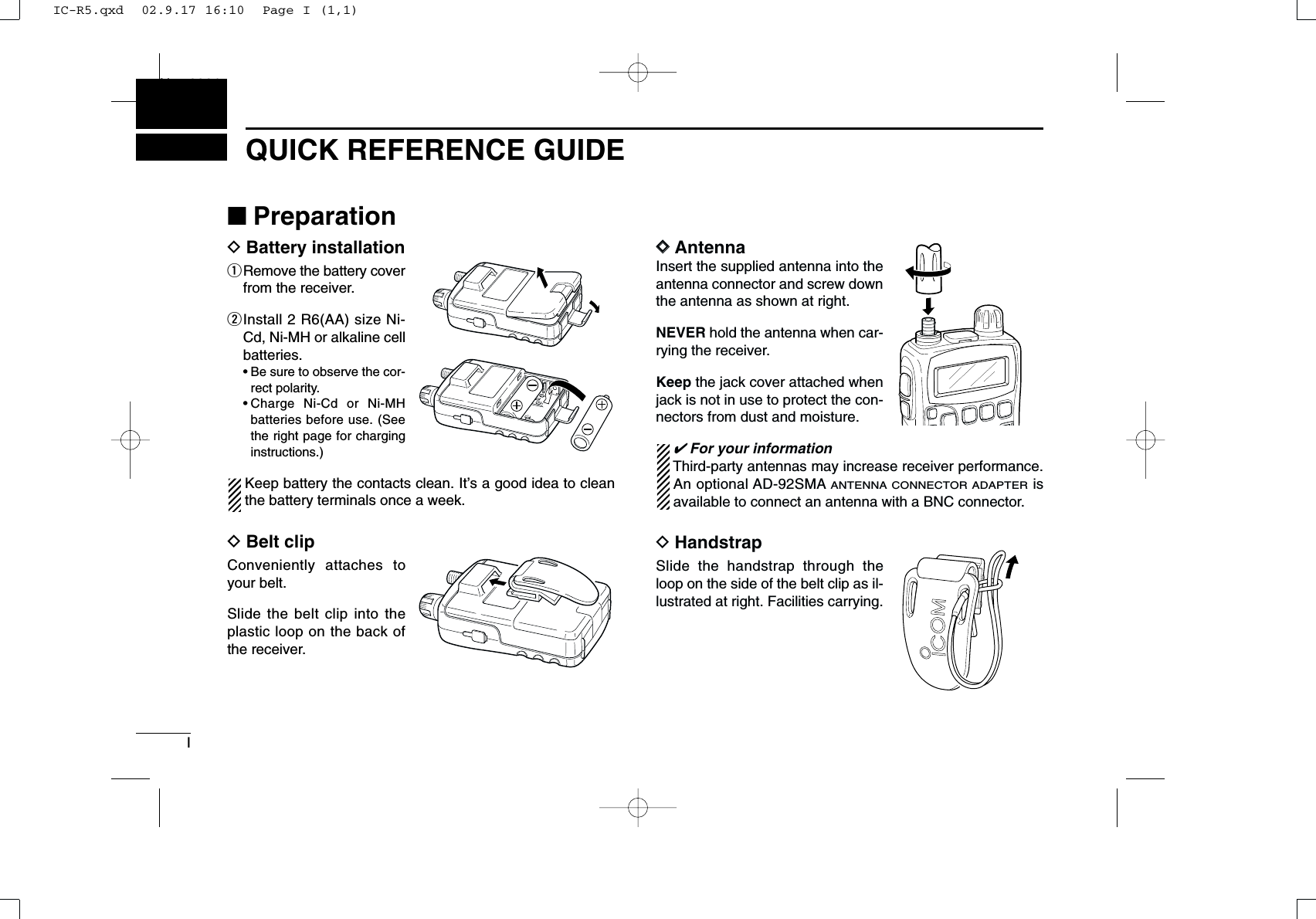
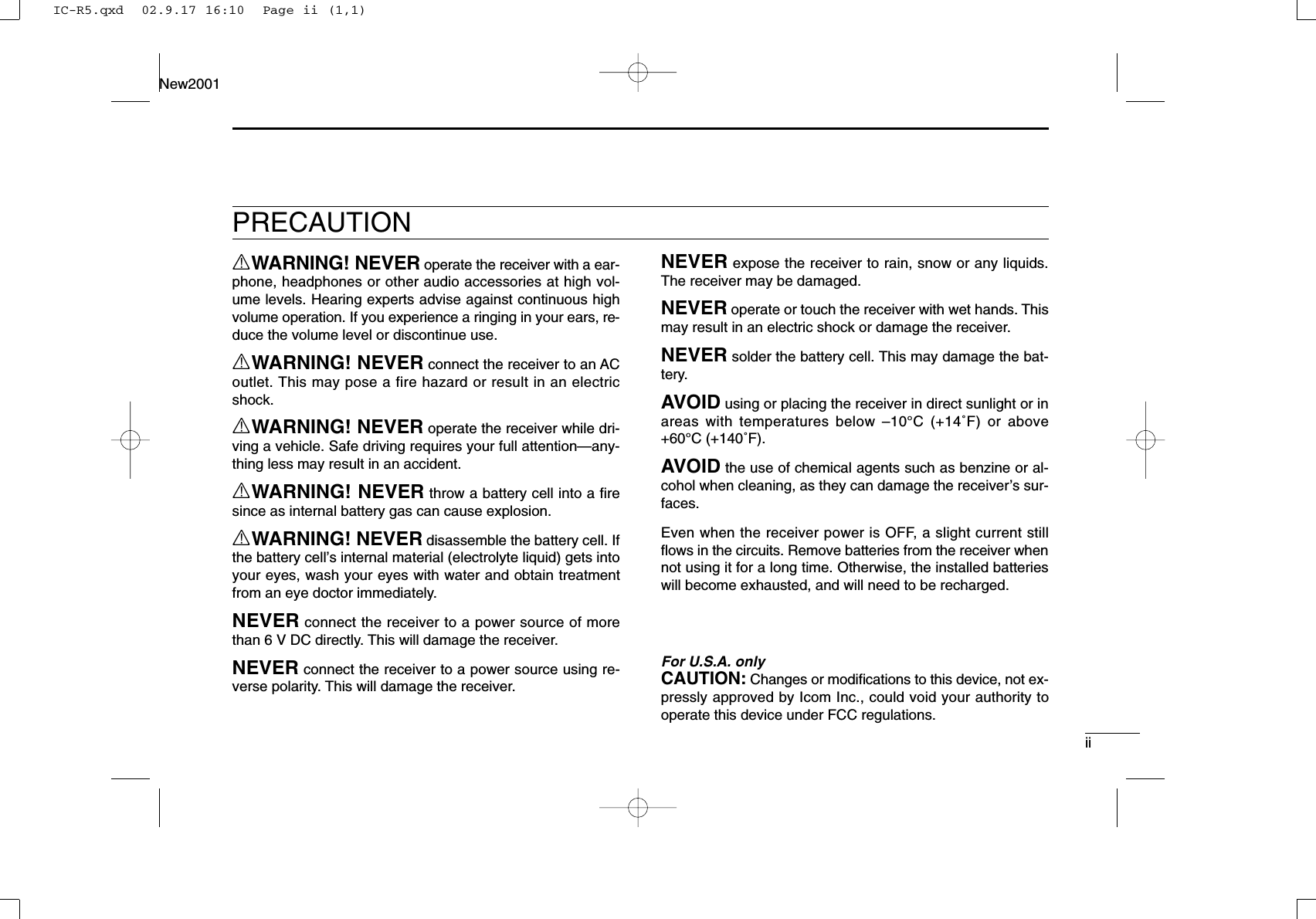
![IIQUICK REFERENCE GUIDENew2001DCharging the batteryqInstall the Ni-Cd batteries.• Ni-MH batteries can also be charged.wPlug the AC adapter into an AC outlet.eInsert the adapter plug into the [DC 6V] of the receiver.rThe battery confirmation is displayed as above right.RRWARNING!:NEVER charge the alkaline batteries. tRotate [DIAL] to select “Y” then push [BAND• ].yThe charging confirmation is displayed as below.uRotate [DIAL] to select “Y” then push [BAND• ] to startbattery charging.• The battery indicator scrolls during charge as below.• Both segments blink when completely charged.[BAND• ][DIAL]IC-R5to [DC 6V]jackOptional CP-18A/ECigarette lighter cable with DC-DC converterAC adapterto cigarette lighter socketto AC outletQuick reference guideIC-R5.qxd 02.9.17 16:10 Page II (1,1)](https://usermanual.wiki/ICOM-orporated/IC-R5/User-Guide-297497-Page-7.png)
![IIIQUICK REFERENCE GUIDENew2001■Your first scanningexperienceNow that you have your IC-R5 ready, you are probably ex-cited to start listening. We would like to take you through afew basic operation steps to make your first “Scanning Expe-rience” enjoyable. DAbout default settingThe [DIAL] control function can be traded with [Y]/[Z] keysfunction in set mode. However, in this QUICK REFERENCEGUIDE, the factory default setting ([DIAL] sets operating fre-quency) is used for simple instruction.DBasic operation1. Turning ON the receiver➥Push [PWR] for 1 sec. to turnthe power ON.2. Adjusting audio level➥Push [Y]/[Z] to set the de-sired audio level.3. Adjusting squelch level➥While pushing [SQL], rotate[DIAL] to set the squelchlevel.4. Tune the desiredfrequencyThe tuning dial will allow you todial in the frequency you want tooperate. Pages 9 and 15 will in-struct you on how to set the tun-ing speed.qPush [BAND•] severaltimes to select the desired fre-quency band.•While pushing [BAND•],rotate [DIAL] also select fre-quency band.wRotate [DIAL] to set the desired receive frequency.•While pushing [FUNC], rotate [DIAL] to select frequency in 1 MHzstep.[DIAL][BAND• ][SQL][Y]/[Z][DIAL][PWR]IC-R5.qxd 02.9.17 16:10 Page III (1,1)](https://usermanual.wiki/ICOM-orporated/IC-R5/User-Guide-297497-Page-8.png)
![IVQUICK REFERENCE GUIDENew20015. Receive mode selection➥Push [MODE•SCAN] severaltimes to select the desired re-ceive mode.•FM, WFM and AM are available.■Memory programmingThe IC-R5 has a total of 1250 memory channels (including200 auto write channels and 50 scan edges) for storing oftenused receive frequency, mode, etc.1. Setting frequencyIn VFO mode, set the desired receive frequency mode.•When “” indicator is displayed, push [V/M•S.MW•~] to se-lect the VFO mode.2. Selecting a memory channelPush [V/M•S.MW•~] for 1 sec.,then rotate [DIAL] to select thedesired memory channel.•“ ” indicator and memorychannel number blink.3. Writing a memory channelPush [V/M•S.MW•~] for 1 sec. until 3 beeps sound.•Memory channel number automatically increases when continuingto push [V/M•S.MW•~] after programming.[V/M•S.MW•~][DIAL][MODE•SCAN]Quick reference guideIC-R5.qxd 02.9.17 16:10 Page IV (1,1)](https://usermanual.wiki/ICOM-orporated/IC-R5/User-Guide-297497-Page-9.png)
![VQUICK REFERENCE GUIDENew2001■Programmed scan operation25 pairs, 50 channels of memories are used for programmedscan operation, that specifying a scanning ranges. The pro-grammed scan scans between “xxA” and “xxB” (xx=00 to 24)frequencies. Therefore, before operating the programmedscan, different frequencies must be programmed into “A” and“B” channels.DDProgramming scan edgesA start frequency must be programmed into a “xxA,” and endfrequency must be programmed into a “xxB” memory chan-nel. 1. Setting frequencyIn VFO mode, set the desired receive frequency mode.•When “” indicator is displayed, push [V/M•S.MW•~] to se-lect the VFO mode.2. Selecting a scan edge channel “A”Push [V/M•S.MW•~] for 1 sec., thenrotate [DIAL] to select one of the de-sired scan edge channel “A.”•“ ” indicator and scan edge channel number blink.3. Writing a memory channelPush [V/M•S.MW•~] for 1 sec. until 3 beeps sound.•Scan edge channel “B” is automatically selected when continuingto push [V/M•S.MW•~] after programming.•After programming is completed, return to VFO indication.4. Selecting a scan edge channel “B”Push [V/M•S.MW•~] for 1 sec., thenrotate [DIAL] to select one of the de-sired scan edge channel “B.”•“ ” indicator and scan edge channel number blink.•When the scan edge channel “B” is already selected at step 3. (con-tinuing to push [V/M•S.MW•~] after programming), skip this step.5. Writing a memory channelPush [V/M•S.MW•~] for 1 sec. until 3 beeps sound.•The next scan edge channel “A” is automatically selected when con-tinuing to push [V/M•S.MW•~] after programming.•After programming is completed, return to VFO indication.IC-R5.qxd 02.9.17 16:10 Page V (1,1)](https://usermanual.wiki/ICOM-orporated/IC-R5/User-Guide-297497-Page-10.png)
![VIQUICK REFERENCE GUIDENew2001DDStarting scan 1. Select VFO mode.Push [V/M•S.MW•~] to select the VFO mode for full, bandand programmed scan operation.•Select memory mode by pushing [V/M•S.MW•~] again for mem-ory or bank scan.2. Selecting a scanning typePush [MODE•SCAN] for 1 sec., then rotate [DIAL] to selectone of the desired scanning type.•Available scan types when VFO mode is selected; “ALL” for fullscan; “BAND” for the selected band; one of “PROGxx” (xx=0 to 24)for programmed scan.•Available scan types when memory bank is selected; “ALL” for allbank scan; “BANK” for the selected bank scan.3. Starting scanPush [MODE•SCAN] to start scan.•Rotate [DIAL] to change the scanning direction.4. Cancelling scanPush [MODE•SCAN] again to stop scan.✔For your informationThe memory channel number you program the scan edgesinto correlate “PROGxx” as follows:00A/00B: Scans between frequencies programmed in 00Aand 00B channels, and select “PROG 00”01A/01B: Scans between frequencies programmed in 01Aand 01B channels, and select “PROG 01”••••23A/23B: Scans between frequencies programmed in 23Aand 23B channels, and select “PROG 23”24A/24B: Scans between frequencies programmed in 24Aand 24B channels, and select “PROG 24”FM AM SKIPPWFM AM SKIPPWFM AM DUP SQL DTCSTWFM AM DUP SQL DTCSTW• Programmed scan• Full/Band scan• Bank scan• Memory/All bank scan[DIAL][MODE•SCAN]•Full scan•Scan type indication examples•Program scan•Bank scanQuick reference guideIC-R5.qxd 02.9.17 16:10 Page VI (1,1)](https://usermanual.wiki/ICOM-orporated/IC-R5/User-Guide-297497-Page-11.png)
![■Front, top and side panelsqANTENNA CONNECTOR (p. I)Connects the supplied antenna.•An optional AD-92SMA is available for connecting an antennawith a BNC connector.wEXTERNAL SPEAKER CONNECTOR [SP]Connect an optional earphone or headphone.The internal speaker will not function when any externalequipment is connected. (See p. 65 for a list of availableoptions.)eFUNCTION SWITCH [FUNC]While pushing this switch, access to secondary function.rSQUELCH SWITCH [SQL] ➥Push and hold to temporarily open the squelch andmonitor the operating frequency. (p. 13)➥While pushing this switch, rotate [DIAL]* to adjust thesquelch level. (p. 12)tUP/DOWN SWITCHES [YY]/[ZZ]Adjusts audio volume level.* (p. 11)yBAND•LOCK SWITCH [BAND•]➥Push to select the operating frequency band. (p. 7)➥After pushing [FUNC], push for 1 sec. to toggle the lockfunction ON and OFF. (p. 10)ui!1o!0!2ytrewqFunction display (pgs 3, 4)Speaker1PANEL DESCRIPTIONNew20011IC-R5.qxd 02.9.17 16:10 Page 1 (1,1)](https://usermanual.wiki/ICOM-orporated/IC-R5/User-Guide-297497-Page-12.png)
![21PANEL DESCRIPTIONNew20011uCONTROL DIAL [DIAL]➥Rotate to select the operating frequency.* (p. 9)➥While scanning, changes the scanning direction.*(p. 26)➥While pushing [SQL], sets the squelch level.* (p. 12)➥While pushing [FUNC], sets the operating frequency in100 kHz, 1 MHz or 10 MHz in VFO mode.* (p. 9)➥While pushing [FUNC], selects the memory channel in10 channels steps in memory mode.* (p. 10)➥While pushing [BAND•], selects the operating bandin VFO mode.* (p. 7)iEXTERNAL DC-IN CONNECTOR [DC 6V] (p. 6)Connects an AC adapter or an optional cigarette lightercable for both charging the installed re-chargeable batteryand operating. oVFO/MEMORY•MEMORY WRITE SWITCH[V/M•S.MW•~~]➥Toggles between VFO and memory mode. (p. 7)➥Push for 1 sec. to enter memory edit condition. (p. 16)➥After pushing [FUNC], select scan skip condition. (p. 30)!0POWER SWITCH [PWR]Push for 1 sec. to turn the receiver power ON and OFF. !1MODE•SCAN SWITCH [MODE•SCAN]➥Push to select the receive mode. (p. 12)➥Push for 1 sec. to start a scan. (p. 26)➥While pushing [FUNC], start a tone scan. (p. 38)!2TUNING STEP•SET SWITCH [TS•SET]➥Push to enter tuning step selecting mode. (p. 9)➥Push for 1 sec. to enter set mode. (p. 39)➥While pushing [FUNC], trade [DIAL] and [Y]/[Z] func-tion. (p. 49)*The function of [DIAL] and [Y]/[Z] can be traded. See page 49 fordetails.IC-R5.qxd 02.9.17 16:10 Page 2 (1,1)](https://usermanual.wiki/ICOM-orporated/IC-R5/User-Guide-297497-Page-13.png)
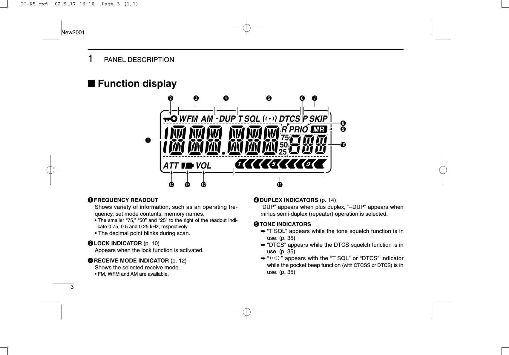
![41PANEL DESCRIPTIONNew20011yAUTO WRITE CHANNEL INDICATOR (p. 29)Appears when auto write channel is selected.uSKIP INDICATORS (p. 30)➥“SKIP” appears when the selected memory channel isspecified as a skip channel.➥“P SKIP” appears when the displayed frequency isspecified as a skip frequency.iPRIORITY WATCH INDICATOR (p. 33)Appears when priority watch is in use.oMEMORY INDICATOR (pgs. 7, 10)Appears when memory mode is selected.!0MEMORY CHANNEL NUMBER INDICATORS Shows the selected memory channel number. (pgs. 7, 10)!1SIGNAL STRENGTH INDICATOR (p. 11)Shows the relative signal strength while receiving signals. !2VOLUME EXCHANGE INDICATOR (p. 49)Appears when the function of [DIAL] and [Y]/[Z] aretraded.!3BATTERY INDICATOR ➥Both segments appear when the installed batteries haveample capacity.•They do not appear when operating with an external powersource.➥Only the right segment “” appears when the batter-ies are nearing exhaustion.➥Scrolls while charging the installed rechargeable batter-ies. (p. 6)➥Both segments blink when completely charged.!4ATTENUATOR INDICATOR (p. 13)Appears when the RF attenuator is in use.IC-R5.qxd 02.9.17 16:10 Page 4 (1,1)](https://usermanual.wiki/ICOM-orporated/IC-R5/User-Guide-297497-Page-15.png)
![5BATTERY CHARGINGNew20012■Battery installationBefore installing, or replacing the batteries, push [PWR] for1 sec. to turn the power OFF.qRemove the batterycover from the receiver.wInstall 2 R6 (AA) size Ni-Cd or Ni-MH batteries.•Be sure to observe the cor-rect polarity.Keep the battery contactsclean to avoid rust orpoor contact. It’s a goodidea to clean the batteryterminals once a week.■CautionDDBattery caution•CAUTION! NEVER short the battery terminals. Also, currentmay flow into nearby metal objects such as a necklace, sobe careful when placing battery cells in handbags, etc.•NEVER mix old and new batteries.•Make sure all battery cells are the same brand, type andcapacity.Either of the above may cause a fire hazard or damage thereceiver if ignored.•NEVER incinerate used battery cells. Internal battery gasmay cause explosion.If your re-chargeable batteries seem to have no capacity evenafter being charged, completely discharge them by leavingthe power ON overnight. Then fully charge the batteriesagain. If the batteries still does not retain a charge (or very lit-tle charge), a new battery cells must be purchased.DDCharging cautionRWARNING! NEVER charge dry or alkaline batteries. AVOID over charging— The installed re-chargeable batteriescan be charged during operation when the AC adapter or theoptional cigarette lighter cable is connected. To prevent overcharging, the IC-R5 has charging timer that automatically dis-connecting the charging line electronically after 15 hours fromcharging. However, the charging timer will reset and startcharging again when disconnect then re-connecting the ACadapter or CP-18A/E more than 1 min. interval.•Recommended temperature for charging:±0˚C to +40˚C (; +32˚F to +140˚F)•Connect the supplied (or optional for UK and Italy versions)AC adapter or optional cigarette lighter cable only whencharging the installed Ni-Cd or Ni-MH batteries. NEVER useother manufactures’chargers.CAUTION: BE SURE to disconnect the CP-18A/E fromthe cigarette lighter socket when charging is finished, be-cause, a slight current still follows in the CP-18A/E and thevehicle’s battery will become exhausted.IC-R5.qxd 02.9.17 16:10 Page 5 (1,1)](https://usermanual.wiki/ICOM-orporated/IC-R5/User-Guide-297497-Page-16.png)
![62BATTERY CHARGINGNew20012■Battery chargingDCharging connections•Charging periods: Approx. 10 hoursDCharging descriptionqInstall the Ni-Cd batteries. (See left page)•Ni-MH batteries can also be charged.wPlug the AC adapter into an AC outlet; or the optional CP-18A/E into a cigarette lighter socket.eInsert the adapter plug into [DC 6V] of the receiver.rThe battery type confirmation is displayed as above right.•When no confirmation display is indicated, insert the adapter plugwhile pushing [FUNC].•Once the batteries are removed for more then 2 sec., the follow-ing operations are necessary.tRotate [DIAL] to select “Y” then push [BAND•].yThe charging confirmation is displayed.uRotate [DIAL] to select “Y” then push [BAND•] to startbattery charging.•The battery indicator scrolls during charge as below.•When the batteries are charged completely, the battery indica-tor (both segments) blinks.•Takes approximately 10 hours for fully charge with the suppliedNi-Cd cells.[BAND• ][DIAL]IC-R5to [DC 6V]jackOptional CP-18A/ECigarette lighter cable with DC-DC converterAC adapterto cigarette lighter socketto AC outletIC-R5.qxd 02.9.17 16:10 Page 6 (1,1)](https://usermanual.wiki/ICOM-orporated/IC-R5/User-Guide-297497-Page-17.png)
![7FREQUENCY AND CHANNEL SETTINGNew20013■VFO and memory channelsThe IC-R5 has 2 normal operating modes: VFO mode andmemory mode.VFO mode is used for the desired frequency setting withinthe frequency coverage.➥Push [V/M•S.MW•~] to select VFO mode.Memory mode is used for the desired frequency settingwithin the frequency coverage.➥Push [V/M•S.MW•~] to select memory mode.•See p. 16 for memory programming details.What is VFO?VFO is an abbreviation of Variable Frequency Oscillator. Fre-quencies for receiving are generated and controlled by theVFO.■Operating band selectionThe receiver can receive the AM broadcast, HF band,50 MHz, FM broadcast, VHF air, 144 MHz, 300 MHz,400 MHz, 800 MHz,* 1200 MHz, television channels orWeather channels†.➥Push [BAND•] several times to select the desired fre-quency band.•When a memory mode is selected, push [V/M•S.MW•~] to se-lect VFO mode first, then push [BAND•] to select the de-sired band.➥While pushing and holding [BAND•], rotating [DIAL]also selects frequency band.Available frequency bands are differ depending on version.See the specification for details.*Some frequency ranges are inhibited for the USA versiondue to local regulation.†Available for the USA version only.[BAND• ][DIAL]FM SKIPPFM[DIAL][V/M•S.MW•~]“ ” and memory channel number appear.• VFO mode indication• Memory mode indicationIC-R5.qxd 02.9.17 16:10 Page 7 (1,1)](https://usermanual.wiki/ICOM-orporated/IC-R5/User-Guide-297497-Page-18.png)
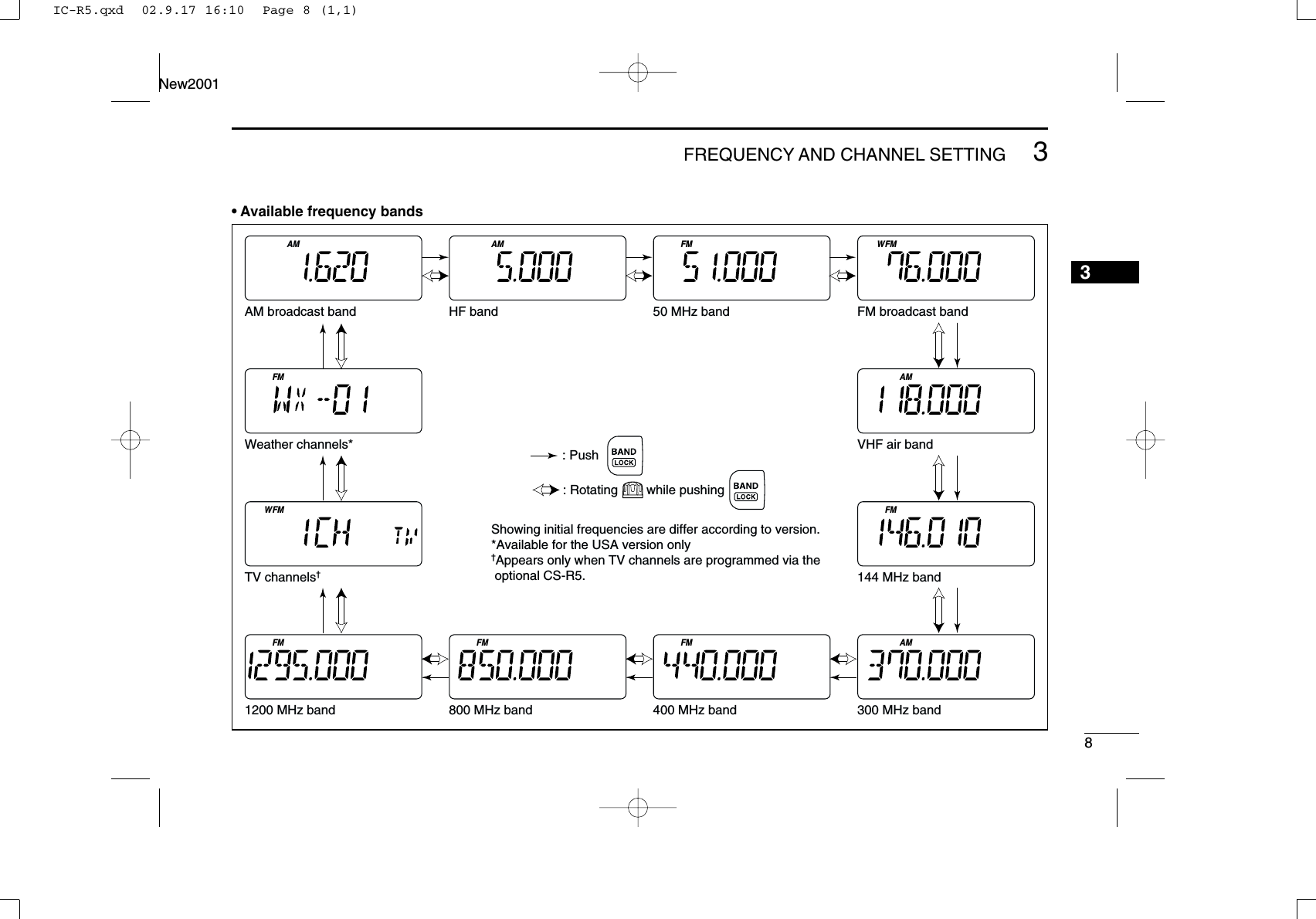
![93FREQUENCY AND CHANNEL SETTING New2001■Setting a frequencyqPush [V/M•S.MW•~] to select VFO mode, if necessary.wSelect the desired frequency band with [BAND•].•Or, while pushing and holding [BAND•], rotate the [DIAL] toselect the desired frequency band.eRotate [DIAL] to select the desired frequency band.•The frequency changes according to the preset tuning steps.See the right section for setting the tuning step.•While pushing and holding [FUNC], rotate [DIAL] to change thefrequency in 1 MHz steps (default).The 1 MHz tuning step (dial select step) can be set to100 kHz, 1 MHz or 10 MHz tuning steps in set mode. Seep. 15 for details.■Setting a tuning stepThe tuning step can be selected for each frequency band,however, the tuning steps, 8.33 kHz and 9 kHz, are appearedwhen setting the tuning step for the VHF air band and AMbroadcast band, respectively. The following tuning steps areavailable for the IC-R5.•5.0 kHz •6.25 kHz •8.33 kHz •9.0 kHz•10.0 kHz •12.5 kHz •15.0 kHz •20.0 kHz•25.0 kHz •30.0 kHz •50.0 kHz •100.0 kHzDDTuning step selectionqPush [V/M•S.MW•~] to select VFO mode, if necessary.wPush [BAND•] to select the desired frequency band.•Or, while pushing and holding [BAND•], rotate the [DIAL] toselect the desired frequency band.ePush [TS•SET] to enter tuning step selecting condition.rRotate [DIAL] to select the desired tuning step.tPush [TS•SET] to return to VFO mode.[DIAL][TS•SET] 5 kHz tuning stepFM755025FM755025[BAND• ][DIAL][FUNC][DIAL] changes the frequency according to the selected tuning step.While pushing [FUNC], [DIAL] changes the frequency in 1 MHz steps (default).IC-R5.qxd 02.9.17 16:10 Page 9 (1,1)](https://usermanual.wiki/ICOM-orporated/IC-R5/User-Guide-297497-Page-20.png)
![103FREQUENCY AND CHANNEL SETTING New20013■Selecting a memory channelqPush [V/M•S.MW•~] to select the memory mode.•“ ” appears when a memory channel is selected.wRotate [DIAL] to select the desired memory channel.•Only programmed memory channels can be selected.•While pushing and holding [FUNC], rotate [DIAL] to select amemory channel in 10 channels steps.■Lock functionTo prevent accidental frequency changes and unnecessaryfunction access, use the lock function. ➥While pushing [FUNC], push [BAND•] for 1 sec. toturn the lock function ON and OFF.•“ ” appears while the lock function is activated.•[SQL] and [Y]/[Z] can be used while the lock function is in usewith default setting. Either or both [SQL] and [Y]/[Z] keys arealso be locked in set mode. (p. 43)FMVOLSKIPP[FUNC]“ ” appears while the lock function is in use.[BAND• ]FM[V/M•S.MW•~][DIAL][FUNC][DIAL] changes the mem-ory channel.IC-R5.qxd 02.9.17 16:10 Page 10 (1,1)](https://usermanual.wiki/ICOM-orporated/IC-R5/User-Guide-297497-Page-21.png)
![11BASIC OPERATIONNew20014■ReceivingMake sure charged Ni-Cd or brand new alkaline batteries areinstalled (p. 5).qPush [PWR] for 1 sec. to turn power ON.wPush [Y] or [Z] to set the desired audio level. •The frequency display shows the volume level while setting. Seethe section at right for details.eSet the receiving frequency. (p. 9)rSet the squelch level. (p. 12)•While pushing [SQL], rotate [DIAL].•The first click of [DIAL] indicates the current squelch level.•“LEVEL 1” is loose squelch and “LEVEL 9” is tight squelch.•“AUTO” indicates automatic level adjustment with a noise pulsecount system.•Push and hold [SQL] to open the squelch manually.tWhen a signal is received:•Squelch opens and audio is emitted.•The S-meter shows the relative signal strength level.■Setting audio volumeThe audio level can be adjusted through 32 levels.➥Push [Y] or [Z] to adjust the audio level. •Beep tone sounds while setting. The tone sound let you know theapproximate sound level.•Pushing and holding either key change the audio level continu-ously.•The display shows the volume level while setting.[Z][Y]INDICATION AUDIO LEVELMinimum setting(no audio)Muximum settingInitial settingq [PWR]e Set frequencyr Set squelch levelw Set audio levele Select bandr Push for setting the squelch (Push to monitor)IC-R5.qxd 02.9.17 16:10 Page 11 (1,1)](https://usermanual.wiki/ICOM-orporated/IC-R5/User-Guide-297497-Page-22.png)
![124BASIC OPERATIONNew20014■Squelch level settingThe squelch circuit mutes the received audio signal depend-ing on the signal strength. The receiver has 9 squelch levels,a continuously open setting and an automatic squelch setting.➥While pushing and holding [SQL], rotate [DIAL] to selectthe squelch level.•“LEVEL 1” is loose squelch and “LEVEL 9” is tight squelch.•“AUTO” indicates automatic level adjustment with a noise pulsecount system.•“OPEN” indicates continuously open setting.■Receive mode selectionReceive modes are determined by the physical properties ofthe radio signals. The receiver has 3 receive modes: FM, AMand WFM modes. The mode selection is stored indepen-dently in each band and memory channels.Typically, AM mode is used for the AM broadcast stations(0.495–1.620 MHz) and air band (118–135.995 MHz), andWFM is used for FM broadcast stations (76–107.9 MHz).➥Push [MODE•SCAN] several times to select the desired re-ceive mode.FM SKIPPAM SKIPPFM SKIPPW[MODE•SCAN]FM modeAM modeWFM mode[SQL][DIAL]Automatic squelchMaximum levelIC-R5.qxd 02.9.17 16:10 Page 12 (1,1)](https://usermanual.wiki/ICOM-orporated/IC-R5/User-Guide-297497-Page-23.png)
![■Monitor functionThis function is used to listen to weak signals without disturb-ing the squelch setting or to open the squelch manually evenwhen mute functions such as the tone squelch are in use.➥Push and hold [SQL] to monitor the operating frequency.•The 1st segment of the S-meter blinks.The [SQL] switch can be set to ‘sticky’operation in ex-panded set mode. See page 43 for details.■Attenuator functionThe attenuator prevents a desired signal from distorting whenvery strong signals are near the desired frequency or whenvery strong electric fields, such as from a broadcasting sta-tion, are near your location.➥While pushing [FUNC], push [SQL] to toggle the attenuatorfunction ON and OFF.•“ATT” appears when the attenuator functions is in use.FMATTSKIPP[SQL][FUNC]“ATT” appears while the attenuator functions is in use.FM SKIPP[SQL] The 1st segment blinks134BASIC OPERATIONNew2001IC-R5.qxd 02.9.17 16:10 Page 13 (1,1)](https://usermanual.wiki/ICOM-orporated/IC-R5/User-Guide-297497-Page-24.png)
![144BASIC OPERATIONNew20014■Duplex operationDuplex communication uses 2 different frequencies for trans-mitting and receiving. Generally, duplex is used in communi-cation through a repeater, some utility communications, etc.During duplex operation, the transmit station frequency isshifted from the receive station frequency by the offset fre-quency. Repeater information (offset frequency and shift di-rection) can be programmed into memory channels. (p. 16)DDSettingqSet the receive station frequency (repeater output frequency).wPush [TS•SET] for 1 sec. to enter set mode.eRotate [DIAL] to select “EXPAND.”•“EXPAND” disappears after 1 sec. and “OFF” (default) and “EX”appear.rWhile pushing [FUNC], rotate [DIAL] to select “ON.”tRotate [DIAL] to select “OFFSET.”•“OFFSET” disappears after 1 sec. and “0.000” (default) and“OW” appear.yWhile pushing [FUNC], rotate [DIAL] to set the desired off-set frequency within 0.000–159.995 MHz range.•The tuning step, selected in VFO mode, is used for setting.uRotate [DIAL] to select “DUP.”•“DUP” disappears after 1 sec. and “OFF” (default) and “DP” ap-pear.iWhile pushing [FUNC], rotate [DIAL] to select “–DUP” or“+DUP.”oPush [TS•SET] to exit set mode.!0Push and hold [SQL] to monitor the transmit station fre-quency (repeater input frequency) directly.Duplex item Setting indicationAfter 1 sec.Offset frequency item Setting indicationAfter 1 sec.[TS•SET][FUNC][DIAL]Expanded set mode item Setting indicationAfter 1 sec.USINGEXPANDED SET MODEIC-R5.qxd 02.9.17 16:10 Page 14 (1,1)](https://usermanual.wiki/ICOM-orporated/IC-R5/User-Guide-297497-Page-25.png)
![154BASIC OPERATIONNew2001■Dial select step [This receiver has a 1 MHz tuning step for quick frequencysetting. This dial select step can be set to 100 kHz, 1 MHz or10 MHz steps, as desired.DDSetting dial select stepqSelect VFO mode with [V/M•S.MW•~].wPush [TS•SET] for 1 sec. to enter set mode.eRotate [DIAL] to select “D SEL.”•“D SEL” disappears after 1 sec. and “1M” (default) and “DS” ap-pear.rWhile pushing [FUNC], rotate [DIAL] to select the desireddial select step.•100 kHz, 1 MHz and 10 MHz can be selected.tPush [TS•SET] momentarily to exit set mode.[TS•SET][FUNC][DIAL]1 MHz step10 MHz step100 kHz stepIC-R5.qxd 02.9.17 16:10 Page 15 (1,1)](https://usermanual.wiki/ICOM-orporated/IC-R5/User-Guide-297497-Page-26.png)
![165MEMORY CHANNELS45■General descriptionThe receiver has 1050 memory channels including 50 scanedge memory channels (25 pairs) for storage of often-usedfrequencies. And a total of 18 memory banks, A to H, J, L, N,O to R, T, U and Y are available for usage by group, etc. Upto 100 channels can be assigned into a bank.DDMemory channel contentsThe following information can be programmed into memorychannels:•Operating frequency (p. 9)•Receive mode (p. 12)•Duplex direction (DUP or –DUP) with an offset frequency(p. 14)•Tone squelch or DTCS squelch ON/OFF (p. 35)•Tone squelch frequency or DTCS code with polarity(pgs. 36, 37)•Scan skip information* (p. 30). ■Memory channel programmingqPush [V/M•S.MW•~] to select VFO mode.wSet the desired frequency:➥Select the desired band with [BAND•].➥Set the desired frequency with [DIAL].➥Set other data (e.g. offset frequency, duplex direction, tonesquelch, etc.), if desired.ePush [V/M•S.MW•~] for 1 sec. to select select memorywrite condition.•1 short and 1 long beep sound.•“ ” indicator memory channel number blink.rRotate [DIAL] to select the desired channel.•Scan edge channel, 00A/B to 24A/B can also be selected.•While pushing [FUNC], rotate [DIAL] to selects memory channelin 10 channels steps.tPush [V/M•S.MW•~] for 1 sec.•3 beeps sound•Memory channel number automatically increases when contin-uing to push [V/M•S.MW•~] after programming.[EXAMPLE]: Programming 145.870 MHz into memory channel 20 (blank channel).FM DUP SQL SKIPTP FM FM DUP SQL SKIPTPFM DUP SQL SKIPTPPush for 1 sec. Push for 1 sec.RotateIC-R5.qxd 02.9.17 16:10 Page 16 (1,1)](https://usermanual.wiki/ICOM-orporated/IC-R5/User-Guide-297497-Page-27.png)
![175MEMORY CHANNELSNew2001■Memory bank settingThe IC-R5 has a total of 18 banks (A to H, J, L, N, O to R, T, Uand Y). Regular memory channels, 000 to 999, are assignedinto the desired bank for easy memory management.qPush [V/M•S.MW•~] for 1 sec. to select select memorywrite condition.•1 short and 1 long beep sound.•“ ” indicator memory channel number blink.wRotate [DIAL] to select the desired memory channel.eWhile pushing [MODE•SCAN], rotate [DIAL] to select“BANK.”•After releasing [MODE•SCAN], “-- -- -- --” is displayed instead ofthe frequency indication, and only “” indicator blinks.•Bank group and channel number is displayed if the selectedmemory channel has already been assigned into a bank, theprevious .•“BANK” item can also be selected by pushing [MODE•SCAN]several times.rWhile pushing [BAND•], rotate [DIAL] to select the de-sired bank group.•Bank group A to H, J, L, N, O to R, T, U and Y are available.•The bank group can also be selected by pushing [BAND•]several times.tRotate [DIAL] to select the desired bank channel number.•Vacant bank channel numbers are only be displayed.yPush [V/M•S.MW•~] momentarily to set the channel intothe bank.•Return to the previous indication.Bank channel is selected with [DIAL]Bank group is selected with [BAND• ][V/M•S.MW•~][MODE•SCAN][DIAL]After [MDE•SCAN] released[BAND• ]IC-R5.qxd 02.9.17 16:10 Page 17 (1,1)](https://usermanual.wiki/ICOM-orporated/IC-R5/User-Guide-297497-Page-28.png)
![185MEMORY CHANNELSNew20015■Memory bank selectionqPush [V/M•S.MW•~] to select memory mode, if desired.wWhile pushing [BAND•], rotate [DIAL] to select the de-sired bank (A to H, J, L, N, O to R, T, U and Y).•The bank can also be selected by pushing [BAND•] severaltimes.•The only programmed banks are displayed.eRotate [DIAL] to select the bank channel.•The only programmed channels are displayed.rTo return to regular memory condition, rotate [DIAL] whilepushing [BAND•], or push [BAND•] several times.FM DUP SQLTBank initialBank chanel numberFM DUP SQLTFM DUP SQLTFMFMR[V/M•S.MW•~][DIAL][BAND• ]Rotate [DIAL] while pushing [BAND• ]Appears only the programmed bank. Auto write channelsIC-R5.qxd 02.9.17 16:10 Page 18 (1,1)](https://usermanual.wiki/ICOM-orporated/IC-R5/User-Guide-297497-Page-29.png)
![195MEMORY CHANNELSNew2001■Programming memory/bank name Each memory channel can be programmed with an alphanu-meric channel name for easy recognition and can be indicatedindependently by channel. Names can be a maximum of 6characters.qPush [V/M•S.MW•~] to select memory mode.wRotate [DIAL] to select the desired memory channel.ePush [V/M•S.MW•~] for 1 sec. to select select memorywrite condition.•1 short and 1 long beep sound.•“ ” indicator and memory channel number blink.rWhile pushing [MODE•SCAN], rotate [DIAL] to select“M NAME” or “B NAME” when programming the memoryname or the bank name, respectively.•The item can also be selected by pushing [MODE•SCAN] sev-eral times.•After releasing [MODE•SCAN], an under bar blinks for the firstdigit instead of the frequency indication, and only “” indicatorblinks.tWhile pushing [FUNC], rotate [DIAL] to select the desiredcharacter.•The selected character blinks.yRotate [DIAL] to move the cursor to left or right.uRepeat steps tand yuntil the desired 6-character chan-nel names are displayed.iPush [MODE•SCAN] several times, or rotate [DIAL] whilepushing [MODE•SCAN] to select “S.MW” item. oPush [V/M•S.MW•~] for 1 sec. to program the name andexit the channel name programming condition.•3 beeps sound.•Available charactersA to Z, 0 to 9, (, ), ✱, +, –, ,, /, |, = and space.NOTE: The bank name can only be programmed into eachbank. Therefore, previously programmed bank name willbe displayed when bank name indication is selected. Andalso, the programmed bank name is assigned for the otherbank channels automatically.Bank nameMemory nameBank name selectionMemory name selectionFM DUP SQLTIC-R5.qxd 02.9.17 16:10 Page 19 (1,1)](https://usermanual.wiki/ICOM-orporated/IC-R5/User-Guide-297497-Page-30.png)
![205MEMORY CHANNELSNew20015■Selecting display typeDuring memory mode operation, one of the programmedmemory name, bank name or the channel number can be dis-played instead of the frequency for your preference.qPush [V/M•S.MW•~] to select memory mode.•[BAND•] to select the desired bank group.wWhile pushing [FUNC], push [BAND•] to select displaytype from frequency, bank name, memory name and chan-nel number indications.DDSelecting bank channel indicationDuring bank channel operation, the bank channel number canalso be displayed instead of the memory channel number in-dication.➥After selecting channel number indication as described atleft, push [BAND•] to select the desired bank.FMFMRFM DUP SQLTFM DUP SQLTPush [BAND• ]Memory channel No. indication Bank channel No. indicationBank channel No. indicationAuto write channel No.FM DUP SQLTFM DUP SQLTFM DUP SQLTFM DUP SQLT[FUNC][BAND• ]Push [BAND• ]while pushing [FUNC]When no memory or bank name is programmed with the selected memory channel, frequency is displayed on the function display.IC-R5.qxd 02.9.17 16:10 Page 20 (1,1)](https://usermanual.wiki/ICOM-orporated/IC-R5/User-Guide-297497-Page-31.png)
![215MEMORY CHANNELSNew2001■Copying memory contentsThis function transfers a memory channel’s contents to VFO(or another memory channel). This is useful when searchingfor signals around a memory channel frequency and for re-calling the offset frequency, subaudible tone frequency etc.DMemory➪VFOqSelect the memory channel to be copied.➥Push [V/M•S.MW•~] to select memory mode, then ro-tate [DIAL] to select the desired memory channel.•Select the bank channel with [BAND•] and [DIAL], if de-sired.wPush [V/M•S.MW•~] for 1 sec. to select select memorywrite condition.•1 short and 1 long beep sound.•“ ” indicator memory channel number blink.eRotate [DIAL] to select “VF.” rPush [V/M•S.MW•~] for 1 sec. again.•VFO mode is selected automatically.Pushing [V/M•S.MW•~] for 2 sec. at the step w, canalso be copied the memory contents to VFO. In this case,the steps eand rare not necessary.DMemory➪memoryqSelect the memory channel to be transferred.➥Push [V/M•S.MW•~] to select memory mode, then ro-tate the tuning dial to select the desired memory channel.wPush [V/M•S.MW•~] for 1 sec. to select select memorywrite condition.•1 short and 1 long beep sound.•“ ” indicator memory channel number blink.•Do not hold [V/M•S.MW•~] for more than 1 sec. otherwise thememory contents will be copied to VFO.eRotate [DIAL] to select the target memory channel.rPush [V/M•S.MW•~] for 1 sec. again to transfer.[EXAMPLE]: Transferring channel 20 to 51.FM DUP SQLTFM DUP SQLTFM DUP SQL SKIPTPPush for 1 sec. RotateSelect memory channelPush for 1 sec.IC-R5.qxd 02.9.17 16:10 Page 21 (1,1)](https://usermanual.wiki/ICOM-orporated/IC-R5/User-Guide-297497-Page-32.png)
![225MEMORY CHANNELSNew20015■Memory clearingContents of programmed memories can be cleared (blanked),if desired.qPush [V/M•S.MW•~] for 1 sec. to select select memorywrite condition.•1 short and 1 long beeps sound.•“ ” indicator and memory channel number blink.•Do not hold [V/M•S.MW•~] for more than 2 sec. otherwise thememory contents will be copied to VFO.wRotate [DIAL] to select the desired memory channel to becleared.eWhile pushing [MODE•SCAN], rotate [DIAL] to select“CLEAR.”•After releasing [MODE•SCAN], “CLR” is displayed instead of thefrequency indication, and only “” indicator blinks.•“CLEAR” item can also be selected by pushing [MODE•SCAN]several times.rPush [V/M•S.MW•~] for 1 sec. to clear the contents.•3 beeps sound.•Return to VFO or memory mode, if VFO is selected before per-forming the step q.•Return to select memory write conditions if memory mode is se-lected before performing the step q.— “” indicator memoryand channel number blink. Push [V/M•S.MW•~] momentarilyto return to memory mode.While pushing [FUNC], push [V/M•S.MW•~] for 1 sec.after the step wis operated can also be cleared the mem-ory contents. In this case, the steps eand rare not nec-essary.☞NOTE: Be careful!— the contents of cleared memoriesCANNOT be re-called even in bank channel opera-tion.Push for 1 sec.[V/M•S.MW•~][MODE•SCAN][DIAL]After [MODE•SCAN] releasedIC-R5.qxd 02.9.17 16:10 Page 22 (1,1)](https://usermanual.wiki/ICOM-orporated/IC-R5/User-Guide-297497-Page-33.png)
![235MEMORY CHANNELSNew2001■Transferring memory contentsContents of programmed memory channels can be trans-ferred to another memory. qPush [V/M•S.MW•~] for 1 sec. to enter select memorywrite condition.•1 short and 1 long beeps sound.•“ ” indicator and memory channel number blink.•Do not hold [V/M•S.MW•~] for more than 2 sec. otherwise thememory contents will be copied to VFO.wRotate [DIAL] to select the desired memory channel to betransferred.eWhile pushing [MODE•SCAN], rotate [DIAL] to select“CLEAR” item.•Pushing [MODE•SCAN] several times also “CLEAR” item is se-lectable.rPush [V/M•S.MW•~] for 1 sec. •The displayed contents are cleared.CONVENIENT!:Instead of the steps eand roperations, while pushingand holding [FUNC], push [V/M•S.MW•~] for 1 sec. alsoclearing the contents.tRotate [DIAL] to select the desired target memory channel.yPush [V/M•S.MW•~] for 1 sec. to transfer the contents.FM DUP SQLTFM DUP SQLT[V/M•S.MW•~][MODE•SCAN][FUNC][DIAL]• Example— Transferring the contents of memory channel 20 to channel 30.Steps q and wStep eStep rStep tStep yIC-R5.qxd 02.9.17 16:10 Page 23 (1,1)](https://usermanual.wiki/ICOM-orporated/IC-R5/User-Guide-297497-Page-34.png)
![245MEMORY CHANNELSNew20015■Erasing/transferring bank contentsContents of programmed memory channels can be or trans-ferred to another memory.INFORMATION: Even if the memory bank contents arecleared, the memory channel contents still remain pro-grammed.qSelect the desired bank contents to be transferred orerased from the bank.➥Push [V/M•S.MW•~] to select memory mode.➥While pushing [BAND•], rotate the [DIAL] to selectthe desired memory bank group.➥Rotate [DIAL] to select the bank channel.•Bank initial stops blinking.•Select the bank channel with [BAND•] and [DIAL], if de-sired.•Bank initial blinks.wPush [V/M•S.MW•~] for 1 sec. to enter select memorywrite condition.•1 short and 1 long beeps sound.•Displays the original memory channel number automatically and“” indicator and memory channel number blink.•Do not hold [V/M•S.MW•~] for more than 2 sec. otherwise thebank contents will be copied to VFO.eWhile pushing [MODE•SCAN], rotate [DIAL] to select“BANK” item.•Pushing [MODE•SCAN] several times, “BANK” item is also se-lectable.rWhile pushing [BAND•], rotate [DIAL] to select the de-sired bank group to be transfer.•Select “-- -- -- --” indication when erasing the contents from thebank.tRotate [DIAL] to select the desired bank channel.yWhile pushing [MODE•SCAN], rotate [DIAL] to select“S.MW” item.•Pushing [MODE•SCAN] several times, “S.MW” item is also se-lectable.uPush [V/M•S.MW•~] for 1 sec.When transferring When erasing FM DUP SQLTFM DUP SQLTPush for 1 sec.IC-R5.qxd 02.9.17 16:10 Page 24 (1,1)](https://usermanual.wiki/ICOM-orporated/IC-R5/User-Guide-297497-Page-35.png)
![25SCAN OPERATIONNew20016■Scan typesScanning searches for signals automatically and makes iteasier to locate new stations for contact or listening purposes.There are 7 scan types and 4 resume conditions to suit youroperating needs.FULL SCAN (p. 26) Repeatedly scans all frequen-cies over the entire band. Some frequency ranges arenot scanned according to thefrequency coverage of the re-ceiver’s version.150kHz1303.995MHzScanJumpSELECTED BAND SCAN(p. 26)Repeatedly scans all frequen-cies over the entire selectedband. BandedgeBandedgeScanJumpALL/SELECTED BANKSCAN (p. 28)Repeatedly scans all bankchannels or selected bankchannels. The skip scan isalso available.SKIPSKIPA99 A03A00 A01 A02A04A98A05FREQUENCY/MEMORYSKIP FUNCTION (p. 30)Skips unwanted frequenciesor channels that inconve-niently stop scanning. Thisfunction can be turned ONand OFF by pushing [FUNC]+ [V/M•S.MW•~] in eitherVFO or memory mode.BandedgeBandedgeScanSKIP SKIPJumpPROGRAMMED SCAN(p. 26)Repeatedly scans betweentwo user-programmed fre-quencies. Used for checkingfor frequencies within a speci-fied range such as repeateroutput frequencies, etc.Bandedge xxA xxBBandedgeScan edgesScanJumpMEMORY (SKIP) SCAN(p. 28)Repeatedly scans memorychannels except those set asskip channels. Skip channelscan be turned ON and OFFby pushing [FUNC] +[V/M•S.MW•~] in memorymode.SKIPSKIPM 0 M 4M 1 M 2 M 3M 5M 199M 6IC-R5.qxd 02.9.17 16:10 Page 25 (1,1)](https://usermanual.wiki/ICOM-orporated/IC-R5/User-Guide-297497-Page-36.png)
![266SCAN OPERATIONNew20016■Full/band/programmed scan qSelect VFO mode with [V/M•S.MW•~].•Select the desired frequency band with [BAND•], if desired.wSet the squelch to the point where noise is just muted.ePush [MODE•SCAN] for 1 sec. to enter scanning type se-lection condition.rRotate [DIAL] to select the desired scanning type.•“ALL” for full scan; “BAND” for band scan, “PROGxx” for pro-grammed scan (xx= 0 to 24; programmed scan edges numbersonly displayed)tTo start the scan, push [MODE•SCAN].•Scan pauses when a signal is received.•Rotate [DIAL] to change the scanning direction, or resumesmanually.•Push [MODE•SCAN] again to stop the scan.NOTE: Instead of the steps eto toperations, whilepushing and holding [MODE•SCAN], rotate [DIAL] to se-lect the desired scan type. In this case, scan starts whenreleasing [MODE•SCAN].About the scanning steps: The selected tuning step ineach frequency band (in VFO mode) is used during scan.FM SKIPPFM SKIPP• During full/band scan • During programmed scan[MODE•SCAN][DIAL]• Full scan selection• Band scan selection• Programmed scan selectionSelectable between “ 0” to “24” if programmedIC-R5.qxd 02.9.17 16:10 Page 26 (1,1)](https://usermanual.wiki/ICOM-orporated/IC-R5/User-Guide-297497-Page-37.png)
![276SCAN OPERATIONNew2001■Scan edges programmingScan edges can be programmed in the same manner asmemory channels. Scan edges are programmed into scanedges, 00A/00B to 24A/24B, in memory channels.qPush [V/M•S.MW•~] to select VFO mode.wSet the desired frequency:➥Select the desired band with [BAND•].➥Set the desired frequency with [DIAL].➥Set other data (e.g. offset frequency, duplex direction, tonesquelch, etc.), if desired.ePush [V/M•S.MW•~] for 1 sec. to select select memorywrite condition.•1 short and 1 long beeps sound.•“ ” indicator and memory channel number blink.rRotate [DIAL] to select the desired programmed scan edgechannel from 00A to 24A.tPush [V/M•S.MW•~] for 1 sec.•3 beeps sound•The other scan edge channel “B,” 00B to 24B, automatically se-lected when continuing to push [V/M•S.MW•~] after program-ming.yTo program a frequency for the other pair of scan edges,00B or 24B, repeat steps wand r.•If the same frequency is programmed into a pair of scan edges,programmed scan will not function.[V/M•S.MW•~][DIAL][EXAMPLE]: Programming 145.300 MHz into scan edges 03A.FM SKIPPFM FM SKIPPFM SKIPPPush for 1 sec. Push for 1 sec.RotateIC-R5.qxd 02.9.17 16:10 Page 27 (1,1)](https://usermanual.wiki/ICOM-orporated/IC-R5/User-Guide-297497-Page-38.png)
![286SCAN OPERATIONNew20016■Memory/bank/all bank scan qSelect memory mode with [V/M•S.MW•~].•Select the desired bank with [BAND•] for bank scan.wSet the squelch to the point where noise is just muted.ePush [MODE•SCAN] for 1 sec. to;• When memory mode is selected at the step qq:- start memory scan.• When a bank channel is selected at the step qq:- enter scan type selection mode.rRotate [DIAL] to select the desired scanning type.•“ALL” for all bank scan; “BANK” for bank scan.tPush [MODE•SCAN] momentarily to start all bank or bankscan.•Scan pauses when a signal is received.•Rotate [DIAL] to change the scanning direction, or resumesmanually.yTo stop the scan, push [MODE•SCAN].IMPORTANT!: To perform memory or bank scan, 2 ormore memory/bank channels MUST be programmed, oth-erwise the scan never starts.FM AM DUP SQL DTCSTWFM AM DUP SQL DTCSTW• During memory/all bank scan • During bank scan[MODE•SCAN][DIAL] • All bank scan selection• Bank scan selectionIC-R5.qxd 02.9.17 16:10 Page 28 (1,1)](https://usermanual.wiki/ICOM-orporated/IC-R5/User-Guide-297497-Page-39.png)
![296SCAN OPERATIONNew2001■Auto memory write scanThis scan is useful for searching a specified frequency rangeand automatically storing busy frequencies into memorychannels. The same frequency ranges used for program scanare used for auto memory write scan.qSelect VFO mode with [V/M•S.MW•~].wPush [MODE•SCAN] for 1 sec. to enter scanning type se-lection condition.eRotate [DIAL] to select the desired scanning type.•“ALL” for full scan; “BAND” for band scan, “PROGxx” for pro-grammed scan (xx= 0 to 24; programmed scan edges numbersonly displayed)rPush [MODE•SCAN] to start the scan.tPush [V/M•S.MW•~] to turn the automatic memory writefunction ON and OFF.•“ ” indicator blinks.yPush [MODE•SCAN] to stop scan.DDDuring auto-memory write scanning:•When signal is received, scan pauses and the frequency isstored into auto memory write channel group (R000–R199).- 2 short beeps sound when stored.•Scan resumes after frequency storing.•When all channels are stored, the scan cancels automati-cally and 1 long beep sounds.DDRe-calling the stored frequencies:qPush [V/M•S.MW•~] to select memory mode.wPush [BAND•] several times, or while pushing[BAND•], rotate [DIAL] to select the auto memory writechannel group.•“R” appears.eRotate [DIAL] to select the desired channel.DDClearing the stored frequencies:qSelect the auto memory write channel group.wWhile pushing [FUNC], push [V/M•S.MW•~] for 1 sec. toclear the all channels contents.•1 short and 1 long beeps sound.NOTE: The auto memory write channel contents CANNOTbe cleared by an independent channel. Thus it is good ideato copy the contents into regular memory channel.FMR“R” appears when auto memory write channel group is selected.FM SKIPP[V/M•S.MW•~][MODE•SCAN][DIAL] • During auto memory write scan“ ” indicator blinks dur-ing auto memory write scan.IC-R5.qxd 02.9.17 16:10 Page 29 (1,1)](https://usermanual.wiki/ICOM-orporated/IC-R5/User-Guide-297497-Page-40.png)
![306SCAN OPERATIONNew20016Memory channels can be set to be skipped for memory skipscan. In addition, memory channels can be set to be skippedfor both memory skip scan and frequency skip scan. Theseare useful to speed up the scan interval.qSelect a memory channel:➥Push [V/M•S.MW•~] to select memory mode.➥Rotate [DIAL] to select the desired channel to be a skipchannel/frequency.wPush [V/M•S.MW•~] for 1 sec. to enter select memorywrite condition.ePush [MODE•SCAN] several times to select “SKIP” item.•While pushing [MODE•SCAN], rotating [DIAL] can also select“SKIP” item.rWhile pushing [FUNC], rotate [DIAL] to select the skip con-dition from “SKIP,” “PSKIP” or “OFF” for the selected chan-nel.•SKIP : The channel is skipped during memory or bank scan. •PSKIP : The channel is skipped during memory/bank scan andthe programmed frequency is skipped during VFO scan,such as programmed scan.•OFF : The channel or programmed frequency is scanned dur-ing any scan.tPush [MODE•SCAN] several times, or while pushing andholding [MODE•SCAN] rotate [DIAL] to select “S.MW” item.yPush [V/M•S.MW•~] for 1 sec. to set the skip condition.•“SKIP” or “P SKIP” indicator appears, according to the skip se-lection in the step r.✔CONVENIENT!The skip setting can also be set with the following operationfor easy setting.qSelect the desired memory channel to be set as a skipchannel/frequency.wWhile pushing [FUNC], push [V/M•S.MW•~] to select theskip condition from “SKIP,” “P SKIP” and “OFF (no indication).”FM SKIPPFM SKIP• Skip channel setting • Program skip setting“SKIP” appears“P SKIP” appears[MODE•SCAN][DIAL]• Skip setting■Skip channel/frequency settingIC-R5.qxd 02.9.17 16:10 Page 30 (1,1)](https://usermanual.wiki/ICOM-orporated/IC-R5/User-Guide-297497-Page-41.png)
![316SCAN OPERATIONNew2001DDScan pause timerThe scan pauses when receiving signals according to thescan pause time. It can be set from 2–20 sec. or unlimited.qPush [TS•SET] for 1 sec. to enter set mode.wRotate [DIAL] to select “EXPAND” item.eWhile pushing [FUNC], rotate [DIAL] to turn the expand setmode selection ON.rRotate [DIAL] to select “PAUSE” item.tWhile pushing [FUNC], rotate [DIAL] to set the desiredscan pausing time from 2–20 sec. (2 sec. steps) and“HOLD.”•“2SEC”–“20SEC”: Scan pauses 2–20 sec. while receiving a sig-nal.•“HOLD”: Scan pauses on a received a signal until itdisappears.yPush [TS•SET] to exit set mode.DDScan resume timerThe scan re-starts after a signal disappears according to theresume time. it can be set from 0–5 sec. or unlimited.qPush [TS•SET] for 1 sec. to enter set mode.wRotate [DIAL] to select “EXPAND” item.eWhile pushing [FUNC], rotate [DIAL] to turn the expand setmode selection ON.rRotate [DIAL] to select “RESUME” item.tWhile pushing [FUNC], rotate [DIAL] to set the desiredscan pausing time from 0–5 sec. (1 sec. steps) and“HOLD.”•“0SEC”: Scan restarts immediately after the signal dis-appears.•“1SEC”–“5SEC”: Scan restarts 1–5 sec. after the signal disap-pears.•“HOLD”: Scan restarts by rotating [DIAL] only.yPush [TS•SET] to exit set mode.[TS•SET][FUNC][DIAL]• Resume timer settingSetting indicationAfter 1 sec.[TS•SET][FUNC][DIAL]• Pause timer settingSetting indicationAfter 1 sec.■Scan resume conditionUSINGEXPANDED SET MODEIC-R5.qxd 02.9.17 16:10 Page 31 (1,1)](https://usermanual.wiki/ICOM-orporated/IC-R5/User-Guide-297497-Page-42.png)
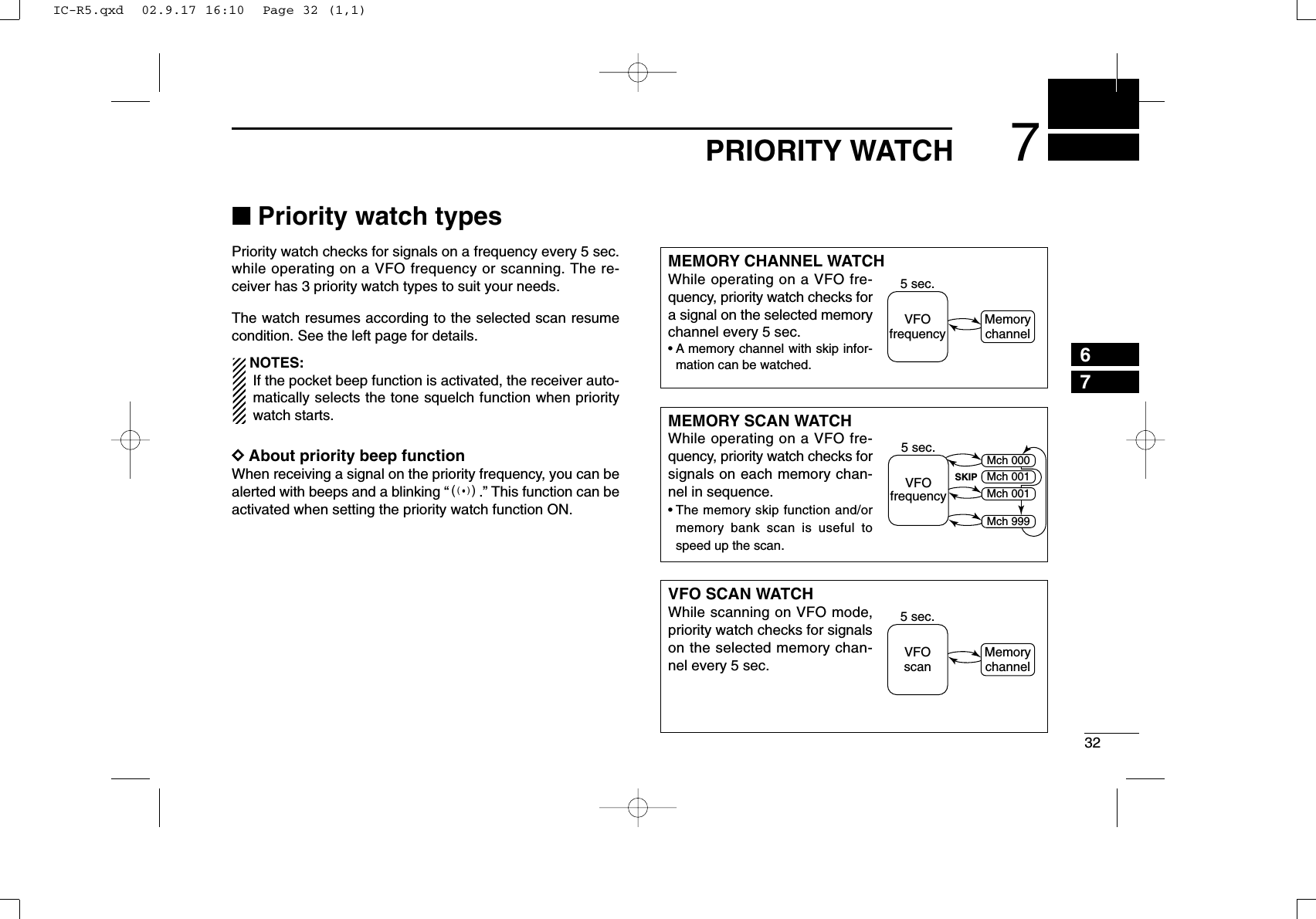
![337PRIORITY WATCHNew2001■Priority watch operationDDMemory channel watch and memory scan watchqSelect VFO mode; then, set an operating frequency.•TV channel can also be selected.wSet the watching channel(s).For memory channel watch:Select the desired memory channel.For memory scan watch:Select memory mode, or the desired bank group; then,push [MODE•SCAN] for 1 sec. to start memory/bank scan.ePush [TS•SET] for 1 sec. to enter set mode.rRotate [DIAL] to select “PRIO” item.tWhile pushing [FUNC], rotate to turn the priority watch ON.•Select “BELL” if the priority beep function is necessary.yPush [TS•SET] to exit set mode and start the watch.•“PRIO” indicator appears.•The receiver checks the memory/bank channel(s) every 5 sec.•The watch resumes according to the selected scan resume con-dition. (p. 31)uPush [TS•SET] to cancel the watch.FM SKIPPPRIOFMPRIOFM SKIPPPRIOFMPRIO• During priority watchMonitors VFO frequency for 5 sec.Pauses on a memory (bank) channel when a signal is received.• During priority watch with priority beepEmits beep and blinks “S” indicator when a signal is received on a memory (bank) channel.[TS•SET][FUNC][DIAL]• Priority setting item• Priority ON• Priority beep ONIC-R5.qxd 02.9.17 16:10 Page 33 (1,1)](https://usermanual.wiki/ICOM-orporated/IC-R5/User-Guide-297497-Page-44.png)
![347PRIORITY WATCHNew20017DDVFO scan watchqSelect memory mode.•Select a memory bank, if desired.wPush [MODE•SCAN] for 1 sec. to start memory/bank scan,if desired.When scanning memory/bank channels:Starts memory/bank scan first. Memory/bank scan can-not be started after VFO scan is started.ePush [TS•SET] for 1 sec. to enter set mode.rRotate [DIAL] to select “PRIO” item.tWhile pushing [FUNC], rotate to turn the priority watch ON.•Select “BELL” if the priority beep function is necessary.yPush [TS•SET] to exit set mode and start the watch.•“PRIO” indicator appears.uPush [MODE•SCAN] for 1 sec. to enter scan type selectioncondition.iRotate [DIAL] to select the desired scan type from “ALL,”“BAND” and “PROGxx (xx= 0–24).”oPush [MODE•SCAN] to start the VFO scan watch.•The receiver checks the memory channel(s) every 5 sec.•The watch resumes according to the selected scan resume con-dition. (p. 31)!0Push [TS•SET] to cancel the watch and scan.FM SKIPPPRIOFMPRIOFM SKIPPPRIOFMPRIO• During VFO scan watchSearches VFO frequen-cies for 5 sec.Pauses on a memory (bank) channel when a signal is received.• During VFO scan watch with priority beepEmits beep and blinks “S” indicator when a signal is received on a memory (bank) channel.IC-R5.qxd 02.9.17 16:10 Page 34 (1,1)](https://usermanual.wiki/ICOM-orporated/IC-R5/User-Guide-297497-Page-45.png)
![35TONE SQUELCH AND POCKET BEEPNew20018■Tone/DTCS squelch operationThe tone or DTCS squelch opens only when receiving a sig-nal with the same pre-programmed subaudible tone or DTCScode, respectively. You can silently wait for the specified sig-nal using the same tone.qSet the desired frequency in FM mode.wPush [TS•SET] for 1 sec. to enter set mode.eRotate [DIAL] to select “EXPAND” item.rWhile pushing [FUNC], rotate [DIAL] to turn the expandedset mode ON.tRotate [DIAL] to select “TSQL” item.yWhile pushing [FUNC], rotate [DIAL] to select the desiredsubaudible tone condition from “TSQL,” “P BEEP,” “DTCS,”“P DTCS” and “OFF.”uPush [TS•SET] to exit set mode.•One of “TSQL,” TSQLS,” “DTCS” or “SDTCS” appears ac-cording to the tone selection in the step y.iWhen a signal with the matched tone is received, thesquelch opens and the receiver emits audio. When pocket beep function is activated, the receiver alsoemits beep tones and blinks “S”.•Beep tones sound and “S” blinks for 30 sec.oPush [FUNC] to stop the beeps and blinking manually.•“S” disappears and the pocket beep function is deactivated.!0To cancel the tone squelch or DTCS, select “OFF” with the“TSQL” item in the expanded set mode, as described in thestep y.FM SQL SKIPTP FM SQL SKIPTPFM DTCS SKIPPFM DTCS SKIPPTone squelch selectionTone squelch with pocket beep function selectionDTCS selection DTCS with pocket beep function selectionTone squelch selectionTone squelch with pocket beep function selectionDTCS selection DTCS with pocket beep function selectionIC-R5.qxd 02.9.17 16:10 Page 35 (1,1)](https://usermanual.wiki/ICOM-orporated/IC-R5/User-Guide-297497-Page-46.png)
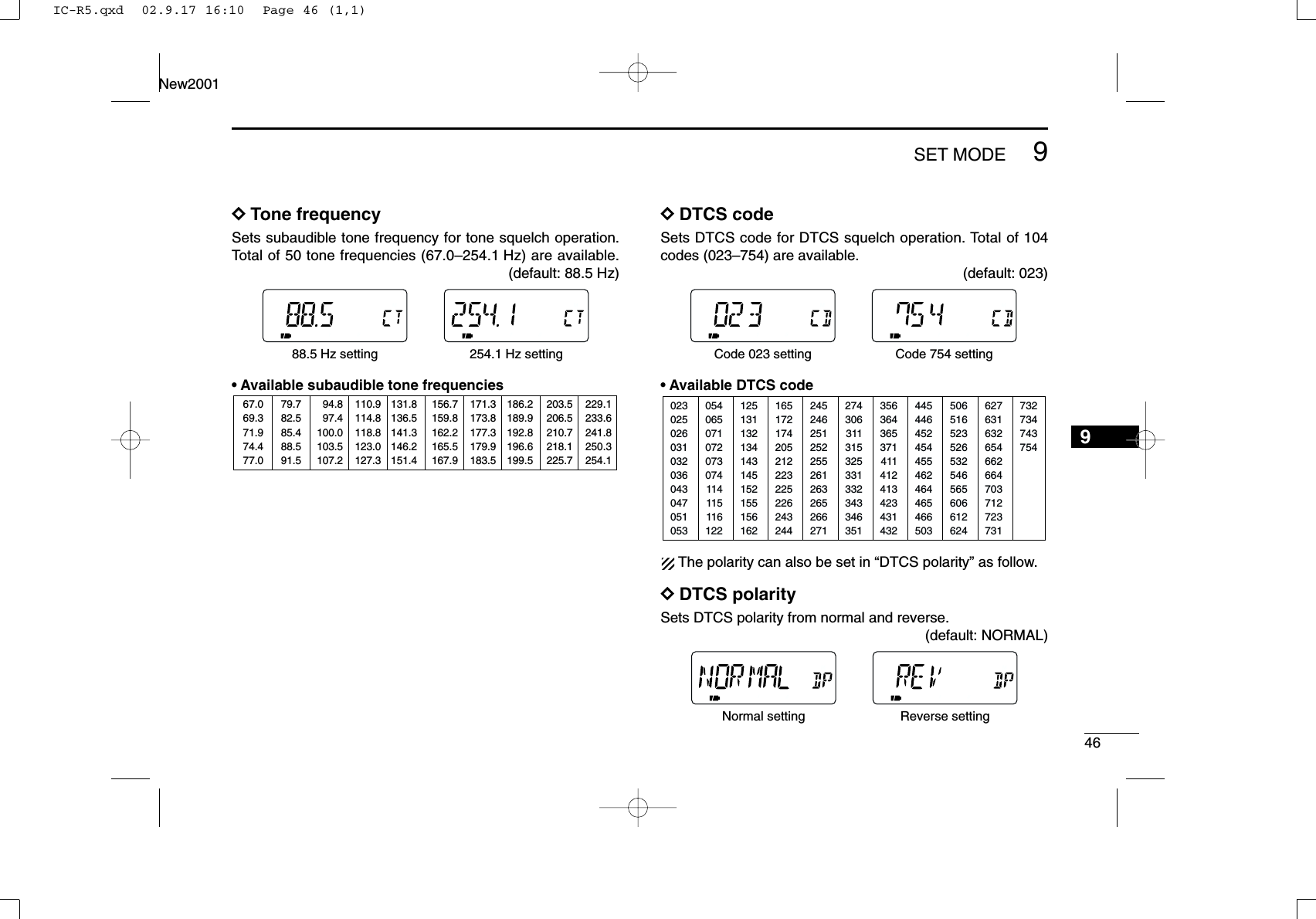
![368TONE SQUELCH AND POCKET BEEPNew20018■Tone squelch frequency/DTCS code setting88.5 Hz and 023 is set as the default for the tone squelch fre-quency and the DTCS code, respectively. The frequency andcode can be selected as desired.qPush [TS•SET] for 1 sec. to enter set mode.wRotate [DIAL] to select “EXPAND” item.eWhile pushing [FUNC], rotate [DIAL] to turn the expandedset mode ON.rRotate [DIAL] to select “TONE” item when selecting thetone squelch frequency; select “CODE” item when select-ing the DTCS code.tWhile pushing [FUNC], rotate [DIAL] to select the desiredsubaudible tone frequency or DTCS code.•See the tables at right.yPush [TS•SET] to exit set mode.•Available tone frequency listNOTE: The receiver has 50 tone frequencies and conse-quently their spacing is narrow compared to units having38 tones. Therefore, some tone frequencies may receiveinterference from adjacent tone frequencies.•Available DTCS code list02302502603103203604304705105312513113213414314515215515616224524625125225526126326526627135636436537141141241342343143250651652352653254656560661262405406507107207307411411511612216517217420521222322522624324427430631131532533133234334635144544645245445546246446546650362763163265466266470371272373173273474375467.069.371.974.477.079.782.585.488.591.594.897.4100.0103.5107.2110.9114.8118.8123.0127.3131.8136.5141.3146.2151.4156.7159.8162.2165.5167.9171.3173.8177.3179.9183.5186.2189.9192.8196.6199.5203.5206.5210.7218.1225.7229.1233.6241.8250.3254.1Tone squelch frequency selectionDTCS code selectionAfter 1 sec.After 1 sec.IC-R5.qxd 02.9.17 16:10 Page 36 (1,1)](https://usermanual.wiki/ICOM-orporated/IC-R5/User-Guide-297497-Page-47.png)
![378TONE SQUELCH AND POCKET BEEPNew2001■DTCS polarity settingAs well as the code setting, the polarity setting is also avail-able for the DTCS operation. When a different polarity is set,the DTCS never releases audio mute even a signal withmatched code number is received.qPush [TS•SET] for 1 sec. to enter set mode.wRotate [DIAL] to select “EXPAND” item.eWhile pushing [FUNC], rotate [DIAL] to turn the expandedset mode ON.rRotate [DIAL] to select “DTCS P” item.tWhile pushing [FUNC], rotate [DIAL] to select the polarityfrom normal (NORMAL) and reverse (REV).yPush [TS•SET] to exit set mode.Normal polarity Reverse polarityAfter 1 sec.[TS•SET][FUNC][DIAL]IC-R5.qxd 02.9.17 16:10 Page 37 (1,1)](https://usermanual.wiki/ICOM-orporated/IC-R5/User-Guide-297497-Page-48.png)
![388TONE SQUELCH AND POCKET BEEPNew20018■Tone scanBy monitoring a signal that is being operated with pocketbeep, tone or DTCS squelch function, you can determine thetone frequency or DTCS code necessary to open a squelch.qSet the frequency to be checked for a tone frequency orcode.wTurn the desired tone type, tone squelch or DTCS, ON inexpanded set mode.•One of “TSQL” or “DTCS” appears. •Even the pocket beep function is activated, the function is can-celled when starts the tone scan.eWhile pushing [FUNC], push [MODE•SCAN] to start thetone scan.•To change the scanning direction, rotate [DIAL].rWhen the CTCSS tone frequency or 3-digit DTCS code ismatched, the squelch opens and the tone frequency orcode is temporarily programmed into the selected condi-tion, such as memory channel.•The tone scan pauses when a CTCSS tone frequency or 3-digitDTCS code is detected.✔For your convenient!Even no tone type is selected, either tone squelch or DTCS,pushing [MODE•SCAN] while pushing and holding [FUNC]also start tone scan. In this case, the tone scan searching fortone squelch frequency only.☞NOTE: The decoded tone frequency or code is pro-grammed temporarily when a memory channel is se-lected. However, this will be cleared when the memorychannel is re-selected.DTCS scanTone squelch scan[MODE•SCAN][FUNC]IC-R5.qxd 02.9.17 16:10 Page 38 (1,1)](https://usermanual.wiki/ICOM-orporated/IC-R5/User-Guide-297497-Page-49.png)
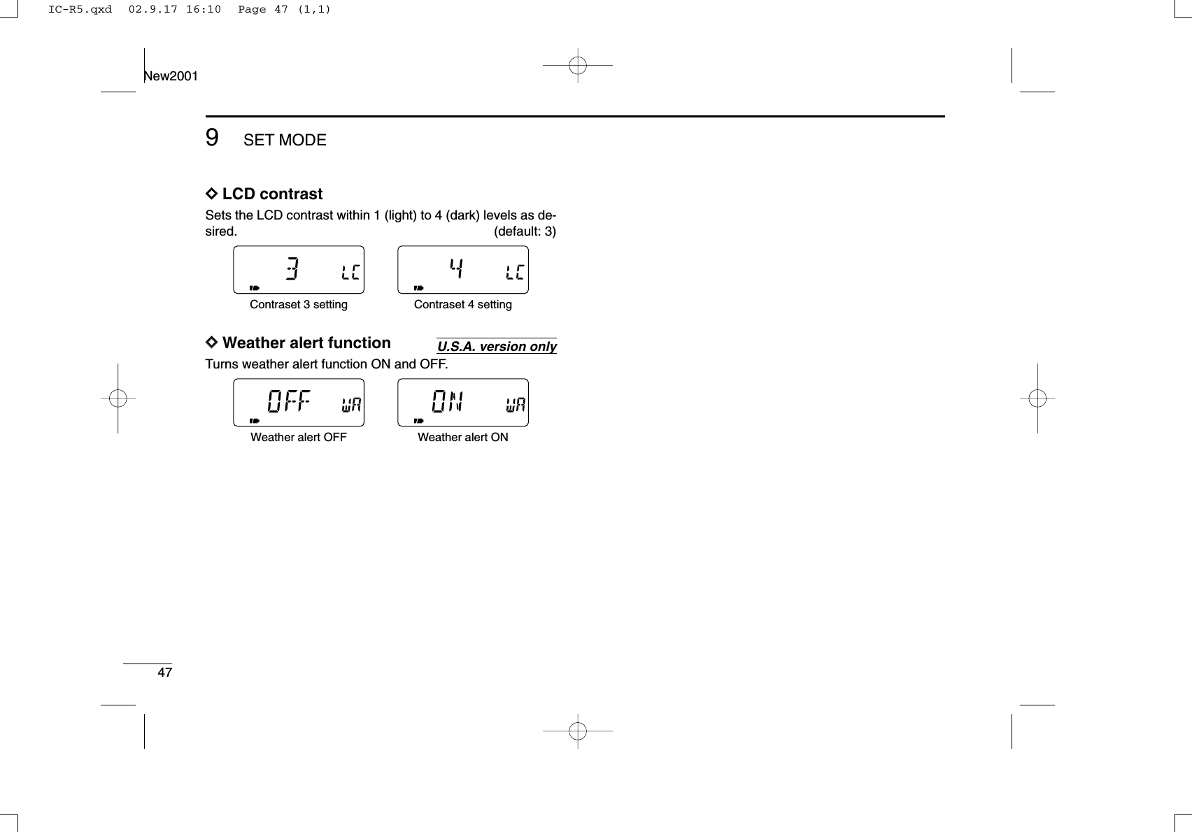
![39SET MODENew20019■GeneralSet mode is used for programming infrequently changed val-ues or conditions of functions.In addition, the IC-R5 has an expanded set mode which isused for programming even more infrequently changed val-ues or conditions of functions. When turning the expandedset mode OFF, only half of the set mode items are displayedfor simple operation.DDSet mode entering and operationqPush [TS•SET] for 1 sec. to enter set mode.wRotate [DIAL] to select the desired item.eWhile pushing [FUNC], rotate [DIAL] to select the desiredvalue or condition.rPush [TS•SET] to exit set mode, or rotate [DIAL] to selectanother set mode item.DDExpanded set mode ON/OFFqPush [TS•SET] for 1 sec. to enter set mode.wRotate [DIAL] to select “EXPAND” item.eWhile pushing [FUNC], rotate [DIAL] to turn the expandedset mode ON and OFF.rRotate [DIAL] to select the desired item.tWhile pushing [FUNC], rotate [DIAL] to select the desiredvalue or condition.yPush [TS•SET] to exit set mode, or rotate [DIAL] to selectanother item.Expanded set mode OFF Expanded set mode ON[TS•SET][FUNC][DIAL]IC-R5.qxd 02.9.17 16:10 Page 39 (1,1)](https://usermanual.wiki/ICOM-orporated/IC-R5/User-Guide-297497-Page-50.png)
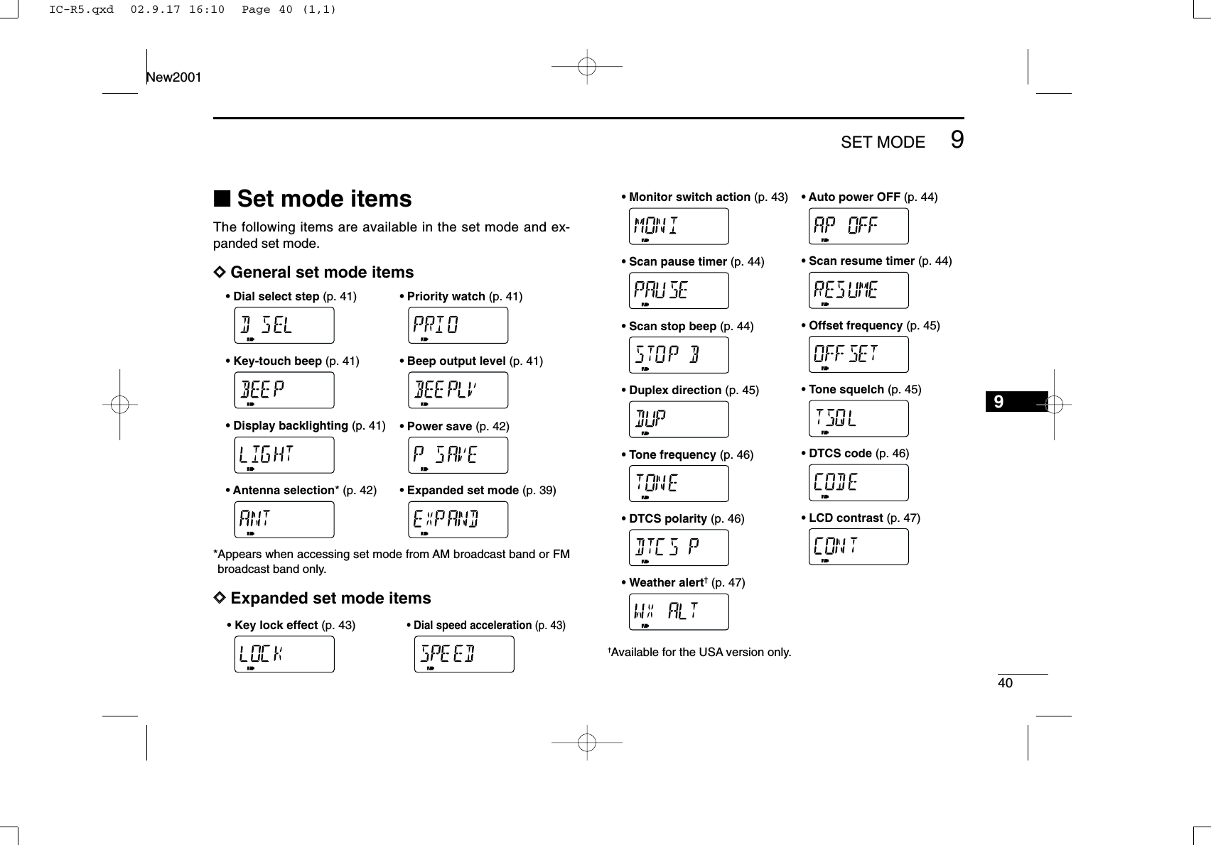
![419SET MODENew2001DDDial select stepSelect the tuning step while pushing [FUNC] from 100 kHz,1 MHz (default) and 10 MHz.DDPriority watchTurn the priority watch or priority beep (priority watch withbeep emission capability) ON. (default: OFF)•ON : Start priority watch after exiting set mode.•BELL : Emits beeps and blinking “S” indicator whena signal is received on the priority frequency.DDKey-touch beepThe key-touch beep can be turned OFF for silent operation. (default: ON)DDBeep output levelAdjust the key-touch beep tone level to the desired levelwithin 32 levels or to the related level with volume control.•VOLUME : The beep tone level is linked with the vol-ume set level. (default)•______ – ooo ooo: The beep tone level is fixed in 32 steps.The key-touch beep (previous item) must be set to ON tohave a beep tone.DDDisplay backlightingThe receiver has display backlighting with a 5 sec. timer fornighttime operation. The backlighting can be turned ON con-tinuously or turned OFF, if desired.•AUTO : Lights when some operation is performed, goesout after 5 sec. (default)•ON : Lights continuously during receiver power is ON.•OFF : Never lights.Auto setting Continuously ON settingRelated to volume level Fixed output levelKey-touch beep ON Key-touch beep OFFPriority watch ON Priority beep ON1 MHz step 100 kHz stepIC-R5.qxd 02.9.17 16:10 Page 41 (1,1)](https://usermanual.wiki/ICOM-orporated/IC-R5/User-Guide-297497-Page-52.png)
![439SET MODENew2001DDKey lock effectWhile the key lock function is ON, [Y]/[Z] and [SQL] can stillbe accessed. Accessible switches can be set to one of 4groups.[PWR] and [FUNC]+[BAND•] are also accessible duringthe lock, however, these switches are not effected by this set-ting.•NORMAL : [Y]/[Z] and [SQL] are accessible. (default)•NO SQL : [SQL] is accessible. •NO VOL : [Y]/[Z] are accessible. •ALL : No accessible switch is available, except[PWR] and [FUNC]+[BAND•].DDDial speed accelerationThe dial speed acceleration automatically speeds up the tun-ing dial speed when rotating [DIAL] rapidly.•ON : The dial speed acceleration is tuned ON. (default)•OFF : The dial speed acceleration is turned OFF.DDMonitor switch actionThe monitor switch, [SQL], can be set as a ‘sticky’switch.When set to the sticky condition, each push of [SQL] togglesthe monitor function ON and OFF.•PUSH : Pushing and holding [SQL] to monitor the fre-quency. (default)•HOLD : Push [SQL] momentarily to monitor the fre-quency and push momentarily again to cancel it.Push and hold [SQL] to monitorPush to monitorThe acceleration ON The acceleration OFFNormal lock conditionAudio output can be adjustedSquelch level can be adjustedReceiver power and lockfunction only switchableIC-R5.qxd 02.9.17 16:10 Page 43 (1,1)](https://usermanual.wiki/ICOM-orporated/IC-R5/User-Guide-297497-Page-54.png)
![449SET MODENew20019DDAuto power OFFThe receiver can be set to automatically turn OFF after aspecified period with a beep when no key operations are per-formed.30 min., 1 hour, 1.5 hours, 2 hours and OFF (default) can bespecified. The specified period is retained even when the re-ceiver is turned OFF by the auto power OFF function. To can-cel the function, select “OFF” in this set mode.DDScan pause timerSelects the scan pause time. When receiving signals, thescan pauses according to the scan pause time.•2–20 : Scan pauses for 2–20 sec. on a received signal,and selected in 2 sec. steps. (default: 10 sec.)•HOLD : Scan pauses on a received signal until it disap-pears. Rotate [DIAL] to resume manually.DDScan resume timerSelects scan resume time. Scan resumes after the specifiedperiod when the received signal disappears.•0 : Scan resumes immediately when the receivedsignal disappears.•1–5 : Scan pause 1–5 sec. after the received signaldisappears. (default: 2 sec.)•HOLD : Scan pauses on the received signal even if itdisappears. Rotate [DIAL] to resume manually.DDScan stop beepTurns the scan stop beep function ON and OFF. When the function is activated (“ON” is selected), a long beepwill sounds each time when signal is received during scan.No beep is sound whenreceiving a signalA long beep is sound whenreceiving a signalScan resumes after 2 sec. Scan resumes manuallyScan pauses for 10 sec. Scan pauses until signal disappears30 min. timer 2 hrs. timerIC-R5.qxd 02.9.17 16:10 Page 44 (1,1)](https://usermanual.wiki/ICOM-orporated/IC-R5/User-Guide-297497-Page-55.png)
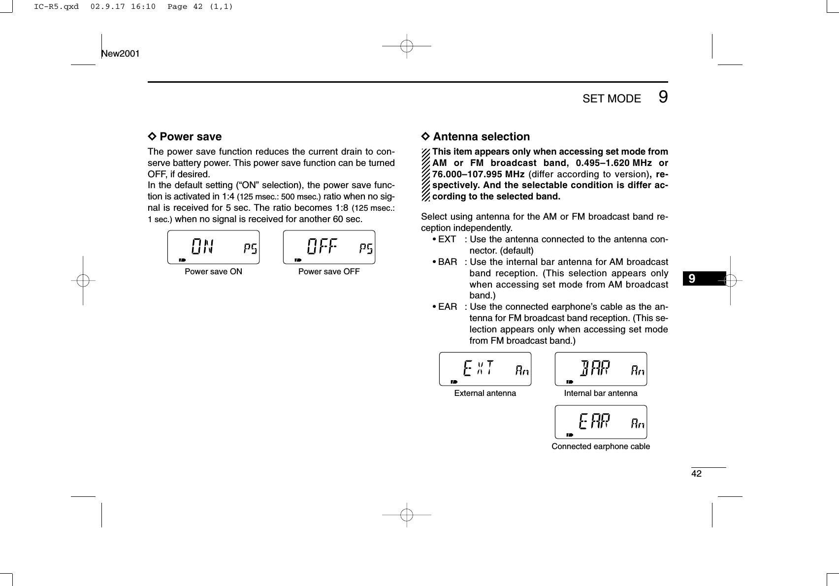
![459SET MODENew2001DDOffset frequencySets the duplex offset frequency for each frequency band in-dependently within 0 to 159.995 MHz range. During duplexoperation (–DUP or +DUP), the monitoring frequency (while[SQL] is pushed) shifts the set frequency. The default value may differ according to the selected fre-quency band (before accessing set mode) and receiver version.The selected tuning step in VFO mode is used for the off-set frequency setting.DDDuplex directionSets the duplex direction. The displaying frequency shifts theprogrammed frequency in offset frequency above when mon-itor function is in use (while pushing [SQL]).•OFF : Simplex operation. (default)•–DUP : The displaying frequency shifts down dur-ing monitor.•+DUP : The displaying frequency shifts up duringmonitor.DDTone squelch Sets tone or DTCS squelch operation and pocket beep capa-bility, when waiting for the desired signal. •OFF : Regular noise squelch operation. (default)•TSQL : Using tone squelch. The squelch opens onlywhen a signal with matched subaudible toneis received.•P BEEP : In addition to the “TSQL” setting, alert beepswill sound when a signal with matched tone isreceived.•DTCS : Using DTCS squelch. The squelch opensonly when a signal with matched DTCS codeis received.•P DTCS : In addition to the “DTCS” setting, alert beepswill sound when a signal with matched DTCScode is received.The subaudible tone frequency and DTCS code is pro-grammed in the tone frequency and DTCS code item, re-spectively.Tone squelch operation Pocket beep operationDTCS squelch operation DTCS beep operationSimplex operation Positive duplex operationIC-R5.qxd 02.9.17 16:10 Page 45 (1,1)](https://usermanual.wiki/ICOM-orporated/IC-R5/User-Guide-297497-Page-56.png)
![4810OTHER FUNCTIONS910■Antenna selectionThe IC-R5 has an internal bar antenna for receiving AMbroadcast band (0.495–1.620 MHz) signals. In addition, theconnected earphone’s cable can be used as an antenna forreceiving FM broadcast band (76.000–107.995 MHz; differ ac-cording to version) signals.DDSelecting antennaqSelect VFO mode with [V/M•S.MW•~].wPush [BAND•] several times, or while pushing[BAND•] rotate [DIAL] to select the AM or FM broad-cast band.ePush [TS•SET] for 1 sec. to enter set mode.rRotate [DIAL] to select “ANT” item.•“ANT” disappears after 1 sec. and “EXT” (default) and “An” ap-pear.tWhile pushing [FUNC], rotate [DIAL] to select “BAR” whenset mode has accessed from the AM broadcast band; se-lect “EAR” when set mode has accessed from the FMbroadcast band.yPush [TS•SET] momentarily to exit set mode.NOTE:•Some noise or spurious may be received when the inter-nal bar or earphone cable is used for antenna.•The supplied or third party’s antenna MUST BE con-nected to the antenna connector to receive signals otherthan AM or FM broadcast bands.•When receiving an AM broadcast signal with internal barantenna, aim the receiver to better audio direction.•When the internal bar or earphone cable is used for an-tenna, the attenuator function cannot be used.Bar antenna selectionfor 0.495–1.620 MHz bandEarphone cable selectionfor 76.000–107.995 MHz band[TS•SET][FUNC][DIAL]After 1 sec.USINGEXPANDED SET MODEIC-R5.qxd 02.9.17 16:10 Page 48 (1,1)](https://usermanual.wiki/ICOM-orporated/IC-R5/User-Guide-297497-Page-59.png)
![4910 OTHER FUNCTIONSNew2001■[DIAL] function assignmentThe [DIAL] control can be used as an audio volume control in-stead of [Y]/[Z] keys to suit your preference. However, while[DIAL] is functions as an audio volume, [Y]/[Z] keys functionas tuning control.➥While pushing [FUNC], push [TS•SET] to toggle the [DIAL]function from tuning dial and audio volume.•“VOL” appears when [DIAL] functions as an audio volume.•[DIAL] and [YY]/[ZZ] functions■Weather channel operationDDWeather channel selectionqSelect VFO mode with [V/M•S.MW•~].wPush [BAND•] several times, or while pushing[BAND•] rotate [DIAL] to select the weather channelgroup.eRotate [DIAL] to select the desired weather channel. rPush [BAND•] to change frequency band, or push[V/M•S.MW•~] to select memory mode.FM[DIAL][BAND• ]Weather channel indicationU.S.A. version onlyFMVOLSKIPP[TS•SET][FUNC]“VOL” appears while [DIAL] functions as an audio volume.No “VOL” indication “VOL” appearsFrequency, Memory channel,Audio volume [DIAL] Squelch level, Scanningdirection, Set mode item and condition setAudio volume setFrequency, Memory channel,[Y]/[Z]Squelch level, Scanning direction, Set mode itemand condition setIC-R5.qxd 02.9.17 16:10 Page 49 (1,1)](https://usermanual.wiki/ICOM-orporated/IC-R5/User-Guide-297497-Page-60.png)
![5010OTHER FUNCTIONSNew200110DDWeather alert functionNOAA broadcast stations transmit weather alert tones beforeimportant weather announcements. When the weather alertfunction is turned ON, the selected weather channel is moni-tored each 5 sec. for the announcement. When the alert sig-nal is detected, the “AL.T” and the WX channel are displayedalternately and sounds a beep tone until the receiver is oper-ated. The previously selected (used) weather channel ischecked periodically during standby or while scanning.qSelect the desired weather channel.wTurn the weather alert function ON in set mode.➥Push [TS•SET] to enter set mode.➥Rotate [DIAL] to select the weather alert item, then ro-tate [DIAL] while pushing and holding [FUNC] to setON.➥Push [TS•SET] to exit set mode.eSet the desired stand-by condition.•Select VFO or memory channel.•Scan or priority watch operation can also be selected.rWhen the alert is detected, a beep sounds and the follow-ing indication will be displayed.tTurn the weather alert function OFF in set mode.NOTE: While receiving a signal (on a frequency other thanthe weather alert ON frequency), the receiving signal oraudio will be interrupted momentarily every 5 sec. (approx.)in case the alert function is turned ON. This symptom iscaused by the WX alert function. To cancel these symp-toms, set the weather alert item OFF in set mode.FM FMShow above indications alternately.IC-R5.qxd 02.9.17 16:10 Page 50 (1,1)](https://usermanual.wiki/ICOM-orporated/IC-R5/User-Guide-297497-Page-61.png)
![5110 OTHER FUNCTIONSNew2001■Data cloningCloning allows you to quickly and easily transfer the pro-grammed contents from one receiver to another; or data froma personal computer to a receiver using the optional CS-R5CLONING SOFTWARE.DCloning between receiversqConnect the OPC-474 cloning cable to the [SP] jack of themaster and sub-receivers.•The master receiver is used to send data to the sub-receiver.wWhile pushing [V/M•S.MW•~], turn power ON to entercloning mode (master receiver only— power ON only for sub-re-ceiver).ePush [SQL] on the master receiver.•The receiver show following indications.rWhen cloning is finished, turn power OFF, then ON to exitcloning mode.During cloningAfter cloningMaster receiver indications Sub-receiver indicationsMaster receiver[V/M•S.MW•~][PWR]“CLONE” and “m” appearwhen entered into cloningmode.to [SP] to [SP]MasterreceiverSub-receiverATPOWER ONIC-R5.qxd 02.9.17 16:10 Page 51 (1,1)](https://usermanual.wiki/ICOM-orporated/IC-R5/User-Guide-297497-Page-62.png)
![5210OTHER FUNCTIONSNew200110DCloning using a personal computerData can be cloned to and from a personal computer (Mi-crosoft®Windows®98/Me/2000/XP) using the optional CS-R5CLONING SOFTWAREand the optional OPC-478U CLONINGCABLE. Consult the CS-R5 CLONING SOFTWAREHELP file fordetails.DCloning error☞NOTE: DO NOT push any key on the sub-receiver duringcloning. This will cause a cloning error.When the display appears as below, a cloning error has oc-curred.In such a case, both receivers automatically return to theclone standby condition and cloning must be repeated.■Auto power-off functionThe IC-R5 can be set to automatically turn OFF after a spec-ified period in which no operation is performed.120 min., 90 min., 60 min., 30 min. and OFF can be specified.The specified period is retained even when the receiver isturned OFF by the auto power-off function. To cancel thefunction, select “OFF” in step ebelow.qPush [TS•SET] for 1 sec. to enter set mode.wRotate [DIAL] to select “AP OFF” item.•Turn the expanded set mode ON for selection. (p. 39)eWhile pushing [FUNC], rotate [DIAL] to select the desiredtime or to turn the function OFF.rPush [TS•SET] to exit set mode.[TS•SET][FUNC][DIAL]After 1 sec.USINGEXPANDED SET MODEMicrosoft and Windows are registered trademarks of Microsoft Corporation inthe U.S.A. and other countries.IC-R5.qxd 02.9.17 16:10 Page 52 (1,1)](https://usermanual.wiki/ICOM-orporated/IC-R5/User-Guide-297497-Page-63.png)
![5310 OTHER FUNCTIONSNew2001■Partial resetIf you want to initialize the operating conditions (VFO fre-quency, VFO settings, set mode contents) without clearingthe memory contents, a partial resetting function is availablefor the receiver.➥While pushing [FUNC] and [TS•SET], turn the power ONto partially reset the receiver.■All resetThe function display may occasionally display erroneous in-formation (e.g. when first applying power). This may becaused externally by static electricity or by other factors.If this problem occurs, turn power OFF. After waiting a fewseconds, turn power ON again. If the problem persists, per-form the following procedure.•Partial resetting is also available. See left for details.IMPORTANT!:Resetting the receiver CLEARS all memory informationand initializes all values in the receiver, including TV chan-nel skip setting.➥While pushing [FUNC] and [V/M•S.MW•~], turn thepower ON to reset the CPU.FM SKIPP[FUNC][V/M•S.MW•~][PWR]*The appearing frqeuency is differ according to receiver version. ATPOWER ON[FUNC][TS•SET][PWR]ATPOWER ONIC-R5.qxd 02.9.17 16:10 Page 53 (1,1)](https://usermanual.wiki/ICOM-orporated/IC-R5/User-Guide-297497-Page-64.png)
![6212MAINTENANCE1112PROBLEM POSSIBLE CAUSE SOLUTION REF.■Troubleshooting If your receiver seems to be malfunctioning, please check thefollowing points before sending it to a service center.No power comes on.No sound comes from thespeaker.Sensitivity is low and onlystrong signals are audible.Frequency cannot be set.No beep sound.Receive audio is distorted.Desired set mode itemcannot be selected.Programmed scan doesnot start.Memory or bank scandoes not start.Installed batteries cannotbe charged.•The batteries are exhausted.•The battery polarity is reversed.•Volume level is too low.•Squelch level is set too tight.•Different tone is selected with tone squelch.•Attenuator function is activated.•The lock function is activated.•Beep tones are turned OFF or the beep tone levelis too low.•The operating mode is not selected correctly.•“EXPAND” item is set to OFF.•Some set mode items can be selected in the AMor FM broadcast band only.•Program scan edges are not programmed.•No or only one memory or bank channel is pro-grammed.•The batteries over discharged.•Replace the batteries or charge the batteries.•Check the battery polarity. •Push [Y] to obtain a suitable level.•While pushing [SQL], rotate [DIAL] to set thesquelch level.•Turn the appropriate function OFF.•While pushing [FUNC], push [SQL] to urn the at-tenuator function OFF.•While pushing [FUNC], push [BAND•] for1 sec. to turn the function OFF.•Turn beep tone ON or set the beep tone level to ap-propriate level in set mode.•Push [MODE•SCAN] several times to select a suit-able operating mode.•Turn “EXPAND” item ON.•Choose the AM or FM broadcast band.•Program a pair of scan edge channels.•Program at least 2 memory or bank channels•Re-install the batteries (wait at least for 1 sec.),then plug the AC adapter while pushing [FUNC].pgs. 5, 6p. 5p. 11p. 12p. 35p. 13p. 10p. 41p. 12p. 39p. 7p. 27pgs. 16,17p. 6IC-R5.qxd 02.9.17 16:10 Page 62 (1,1)](https://usermanual.wiki/ICOM-orporated/IC-R5/User-Guide-297497-Page-73.png)
![New2001qwiR5■ VFO and memory mode selectionPOCKET GUIDEPush [V/M•S.MW•~] to toggle between VFO and memory mode.➥■ Receive mode selectionPush [MODE•SCAN] several times to select the desired mode➥■ Audio level settingPush [Y] to increase, push [Z] to decrease the audio level.➥■ Squelch level settingWhile pushing [SQL], rotate [DIAL] to set the squelch level.➥■ Frequency band selectionPush [BAND• ] several times, or while pushing [BAND• ], rotate [DIAL] to select the desired frequency band.➥■ Tuning step selectionPush [TS•SET], then rotate [DIAL] to select the desired tuning step.• Push [TS•SET] again to return to the previous condition.➥■ Key lock functionWhile pushing [FUNC], push [BAND• ] for 1 sec. to toggle the key lock function ON and OFF.• “ ” appears when the lock function is in use.➥■ Frequency settingPush [V/M•S.MW•~] to select VFO mode.Rotate [DIAL] to set the desired operating frequency. qw■ Memory channel selectionPush [V/M•S.MW•~] to select memory mode.Rotate [DIAL] to set the desired memory channel.• While pushing [FUNC], [DIAL] rotation changes memory channel in 10 channels steps.qwe■ Memory bank channel selectionPush [V/M•S.MW•~] to select memory mode.Push [BAND• ] several times, or while pushing [BAND• ], rotate [DIAL] to select the desired bank.Rotate [DIAL] to select the desired bank channel.■ Attenuator functionWhile pushing [FUNC], push [SQL] to toggle the attenuator ON and OFF.• “ ” appears when the lock func-tion is in use.➥6615POCKET GUIDEImportant operating instructions are summed up in this and the followingpage for your simple reference.By cutting along the line and folding on the dotted line, it will become a cardsized operating guide which can easily be carried in a card case or wallet,etc.q Cut w Fold e Complete<CUT HERE>IC-R5.qxd 02.9.17 16:11 Page 66 (1,1)](https://usermanual.wiki/ICOM-orporated/IC-R5/User-Guide-297497-Page-77.png)
![New2001qwer■ Memory channel programmingSet the desired frequency and other functions in VFO mode.Push [V/M•S.MW•~] for 1 sec. to enter select memory write condition.• 1 short and 1 long beeps sound.Rotate [DIAL] to select the desired memory channel number.Push [V/M•S.MW•~] for 1 sec. again to program the contents into the selected channel.• 3 beeps sound.qwe■ Scan skip settingPush [V/M•S.MW•~] to select memory mode.Rotate [DIAL] to select the desired memory channel.While pushing [FUNC], push [V/M•S.MW•~] to set the skip setting (skip channel or skip frequency) ON and OFF.qw■ VFO scansPush [V/M•S.MW•~] to select VFO mode.Push [MODE•SCAN] for 1 sec.• One of scan type “ALL,” “BAND” or “PROG xx” (xx= 0–24) appear. erRotate [DIAL] to select the desired scan type.Push [MODE•SCAN] momen-tarily to start scan.• Rotate [DIAL] to change the scanning direction.• During scan, push [V/M•S.MW•~] to start auto memory write scan.Push [MODE•SCAN] momen-tarily again to stop scan.qw■ Memory scansPush [V/M•S.MW•~] to select memory mode.• Push [BAND• ] to select a bank, if desired.Push [MODE•SCAN] for 1 sec.• One of scan type “ALL” or “BANK” appear, for bank scan. Rotate [DIAL] to select the desired scan type, in this case.• When memory mode is selected at step q, memory scan starts.erPush [MODE•SCAN] momen-tarily to start bank scan.• Rotate [DIAL] to change the scanning direction.Push [MODE•SCAN] momen-tarily again to stop scan.IC-R5.qxd 02.9.17 16:11 Page 67 (1,1)](https://usermanual.wiki/ICOM-orporated/IC-R5/User-Guide-297497-Page-78.png)