ICOM orporated IC-R75 User Manual US IC R75 IM 1
ICOM Incorporated US IC R75 IM 1
UserManual.wiki
>
ICOM orporated
>
IC-R75 User Manual
>
manual
Contents
1.
manual
2.
User Manual
manual
Navigation menu
Upload a User Manual
Namespaces
Wiki Guide
HTML
PDF
Info
Views
User Manual
Discussion / Help
Navigation
![iIMPORTANTREAD THIS INSTRUCTION MANUALCAREFULLY before attempting to operate the re-ceiver.SAVE THIS INSTRUCTION MANUAL. Thismanual contains important safety and operating in-structions for the IC-R75.EXPLICIT DEFINITIONSRNEVER apply AC to the [DC13.8V] jack on the re-ceiver rear panel.This could cause a fire or ruin the re-ceiver.RNEVER apply more than 16 V DC, such as a 24 Vbattery, to the [DC13.8V] jack on the receiver rearpanel. This could cause a fire or ruin the receiver.RNEVER let metal, wire or other objects touch anyinternal part or connectors on the rear panel of the re-ceiver. This may result in an electric shock.NEVER expose the receiver to rain, snow or any liq-uids.AVOID using or placing the receiver in areas with tem-peratures below –10°C (+14°F) or above +60°C(+140°F). Be aware that temperatures on a vehicle’sdashboard can exceed 80°C (+176°F), resulting in per-manent damage to the receiver if left there for ex-tended periods.AVOID placing the receiver in excessively dusty envi-ronments or in direct sunlight.AVOID placing the receiver against walls or puttinganything on top of the receiver. This will obstruct heatdissipation.Place unit in a secure place to avoid inadvertent use by chil-dren.During mobile operation, DO NOT operate the receiverwithout running the vehicle’s engine. When receiverpower is ON and your vehicle’s engine is OFF, the ve-hicle’s battery will soon become exhausted.Make sure the receiver power is OFF before startingthe vehicle. This will avoid possible damage to the re-ceiver by ignition voltage spikes.The receiver comes with the following accessories.Qty.qAC adapter (AD-55/A/V)* ..................................... 1wDC power cable (OPC-869)* ............................... 1eFuse (FGB 3 A; internal use) ............................... 1rFuse (FGB 3 A; for DC cable)* ............................ 2*Either AC adapter + 1 fuse (q, e) or DC power cable + 3fuses (w, e, r) are supplied depending on versions.PRECAUTIONSSUPPLIED ACCESSORIESVersions of the IC-R75 which display the “CE” symbol onthe serial number seal comply with the European har-monised standard ETS300 684 (EMC product standardfor Commercially Available Amateur Radio Equipment).WORDR WARNINGCAUTIONNOTEDEFINITIONPersonal injury, fire hazard or electric shock may occur.If disregarded, inconvenience only. No risk of personal injury, fire or electric shock.Equipment damage may occur.q wer](https://usermanual.wiki/ICOM-orporated/IC-R75.manual/User-Guide-30547-Page-2.png)
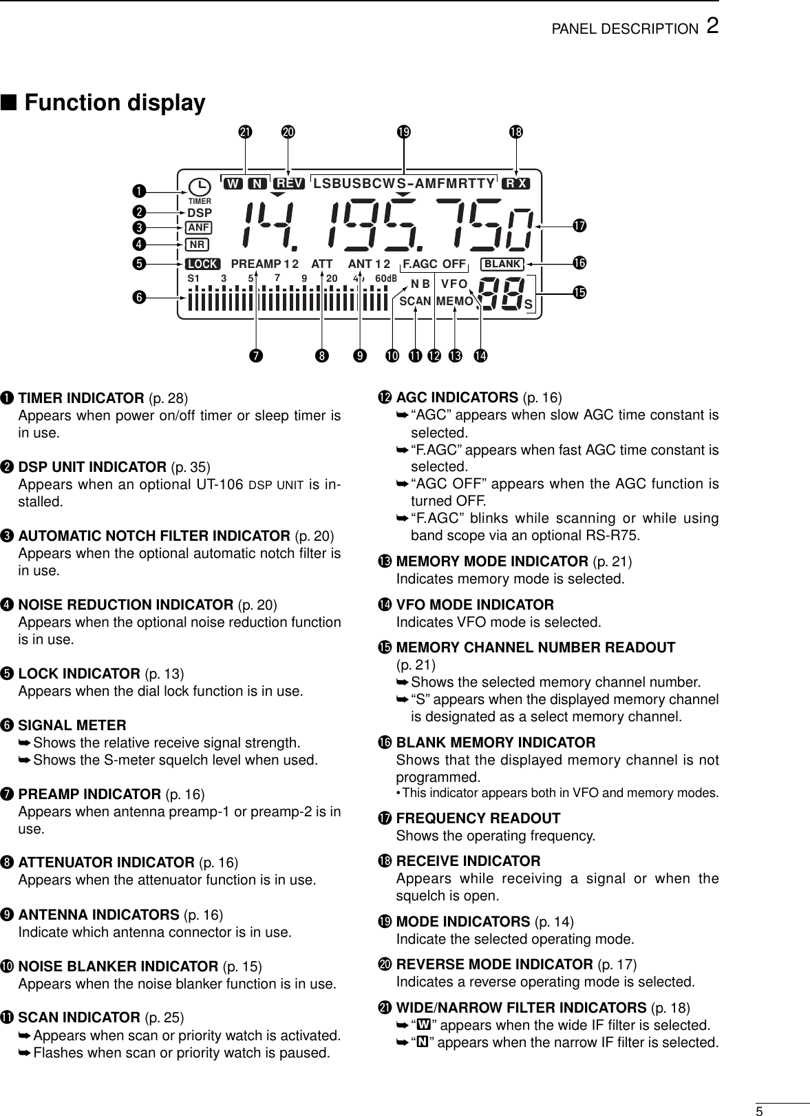
![■Front panelqPOWER SWITCH [POWER]➥Push momentarily to turn power ON.•Turn the optional DC power supply ON in advance.➥Push for 2 sec. to turn power OFF.wHEADPHONE JACK [PHONES] (p. 8)Accepts headphones.•When headphones are connected, the internal speakeror connected external speaker does not function.eAF CONTROL [AF] (inner control)Varies the audio output level from the speaker.rRF GAIN/SQUELCH CONTROL [RF/SQL](outer control; pgs. 14, 30)Adjusts the squelch threshold level.The squelch re-moves noise output from the speaker (closed con-dition) when no signal is received.•The squelch is particularly effective for FM. It is alsoavailable for other modes.•The control can be set as the squelch plus RF gain con-trols or squelch control only (RF gain is fixed at maxi-mum) in set mode.tPASSBAND TUNING CONTROLS [TWIN PBT](p. 15)Adjust the receiver’s “passband width” of the 455kHz and 9 kHz IF filters for the inner and outer con-trols, respectively.•Set to the center positions when not in use.yCLOCK MODE SWITCH [CLOCK] (p. 28)Toggles between frequency indication and clock in-dication when pushed.uANTENNA SELECTOR/SET MODE SWITCH[ANT/SET] (pgs. 16, 30)➥While in a frequency indication, enters set modewhen pushed.➥While in a frequency indication, toggles betweenthe antenna 1 and 2 connectors when pushed for2 sec.➥While in the clock indication, enters time settingcondition when pushed for 2 sec.➥While in a timer indication, toggles the timer ONor OFF when pushed.iTUNING DIALChanges the displayed frequency, selects set modeitems, etc.oTUNING DIAL TENSION LATCHAdjusts the tension of the tuning dial.!0 LOCK/SPEECH SWITCH [LOCK] (pgs. 13, 34)➥Toggles the frequency lock function ON and OFF.➥Announces the selected readout frequency whenan optional UT-102 is installed and when pushedfor 2 sec.22PANEL DESCRIPTIONFILTSCW/RTTYFMSSBAMPHONES POWERRF/SQL TWIN PBTAFCOMMUNICATIONS RECEIVERDN UP12ABC3DEF4GHI5JKL6MNO7PRS8TUV9WXY.0QZENTV/M MWSEL SCANCLRLOCKAGCNBANFNRATTP.AMPSETCLOCKANTFunction display (p. 5)Speakerqwe r t y i o !0 !1!3!4!5!6!7!8!2u](https://usermanual.wiki/ICOM-orporated/IC-R75.manual/User-Guide-30547-Page-4.png)
![32PANEL DESCRIPTION!1 MEMORY CHANNEL UP/DOWN SWITCHES [√√DN]/[UP∫∫](p. 21)➥Select a memory channel.➥Select a set mode contents while in set mode.➥Select a timer or time indication while in clock in-dication.➥Select a filter set mode contents while in filter setmode.!2 MEMORY WRITE SWITCH [MW] (pgs. 22, 27)➥Stores the displayed frequency and operatingmode into the selected memory channel whenpushed for 2 sec.➥Toggles the programmed scan and auto memorywrite scan when pushed.!3 CLEAR SWITCH [CLR] (p. 24)➥Clears the input digits while inputting a frequencyor memory channel number.➥Clears the selected memory channel contentswhen pushed for 2 sec. in memory mode.•This switch does not function in VFO mode.!4 VFO/MEMORY SWITCH [V/M] (pgs. 21, 23)➥Toggles the operating mode between VFO modeand memory mode when pushed.➥Selects a memory channel for inputting a mem-ory channel number when pushed.➥Transfers the memory contents to VFO whenpushed for 2 sec.!5 KEYPAD (pgs. 11, 21)The keypad can be used for several functions asbelow:•Keypad then [ENT]— Direct frequency input.•Keypad then [V/M]— Memory channel selection.•[ENT] then keypad in memory name indicationmode— Alphanumeric input for memory name, etc.!6 QUICK TUNING STEP SWITCH [TS] (pgs. 12, 13)➥Selects a quick tuning step or turns the quick tun-ing step OFF.•While the quick tuning indicator (6) is displayed, thefrequency can be changed in kHz or MHz steps.➥While the quick tuning step is OFF, turns the 1 Hzstep ON and OFF when pushed for 2 sec.•1 Hz indication appears and the frequency can bechanged in 1 Hz steps.➥While the kHz quick tuning step is selected, en-ters tuning step set mode when pushed for 2 sec.➥While the memory name indication is selected inmemory mode, pushing this switch shows the op-erating frequency; and rotating the tuning dialwhile pushing this switch changes the frequencytemporally.!7 FILTER SWITCH [FIL] (pgs. 18, 19)➥Push momentarily to toggle between the pre-pro-grammed normal, wide and narrow IF filters forthe selected operating mode.➥Push for 2 sec. to enter filter set mode.!8 MODE SWITCHES [SSB]/[CW/RTTY]/[AM]/[FM](p. 14)Select an operating mode.•Push [SSB] to toggle between LSB and USB.•Push [CW/RTTY] to toggle between CW and RTTY.•Push [CW/RTTY] for 2 sec. to toggle between CW andCW reverse or RTTY and RTTY reverse.•Push [AM] to toggle between AM and S-AM.•Push [FM] to select FM.](https://usermanual.wiki/ICOM-orporated/IC-R75.manual/User-Guide-30547-Page-5.png)
![42PANEL DESCRIPTION■Front panel (continued)!9 PREAMP SWITCH [P.AMP] (p. 16)Push to toggle between preamp-1 and preamp-2 orturn the preamp OFF.@0 ATTENUATOR SWITCH [ATT] (p. 16)Push to toggle the 20 dB attenuator function ONand OFF.@1 NOISE REDUCTION SWITCH [NR] (p. 20)➥Toggles the optional noise reduction function ONand OFF when pushed. Functions in SSB, CWand RTTY modes. An optional UT-106 DSP UNIT isrequired.➥Enters noise reduction level set mode whenpushed for 2 sec. An optional UT-106 DSP UNIT isrequired.@2 AUTOMATIC NOTCH FILTER SWITCH [ANF](p. 20)Push to turn the optional automatic notch filter forreceiving AM signals ON and OFF. An optionalUT-106 DSP UNIT is required.@3 NOISE BLANKER SWITCH [NB] (p. 15)Toggles the noise blanker ON and OFF. The noiseblanker reduces pulse-type noise such as that gen-erated by automobile ignition systems.This functionis not effective for FM, or non pulse-type noise.@4 AGC SWITCH [AGC] (p. 16)➥Toggles the AGC (Automatic Gain Control) timeconstant fast and slow when pushed.➥Toggles the AGC function ON and OFF whenpushed for 2 sec.@5 SELECT SWITCH [SEL] (pgs. 24, 26)➥Toggles the select memory setting ON and OFFwhen pushed in memory mode.➥Toggles the memory name indication ON andOFF when pushed for 2 sec. in memory mode.@6 SCAN SWITCH [SCAN] (p. 25)➥Push momentarily to start/stop the programmedscan in VFO mode.➥Push momentarily to start/stop the memory scanin memory mode.➥Push for 2 sec. to start the priority watch in VFOmode.•Push [SCAN] again to cancel the priority watch.FILTSCW/RTTYFMSSBAMPHONES POWERRF/SQL TWIN PBTAFCOMMUNICATIONS RECEIVERDN UP12ABC3DEF4GHI5JKL6MNO7PRS8TUV9WXY.0QZENTV/M MWSEL SCANCLRLOCKAGCNBANFNRATTP.AMPSETCLOCKANTFunction display (p. 5)!9 @0 @1 @2 @3 @4@6@5](https://usermanual.wiki/ICOM-orporated/IC-R75.manual/User-Guide-30547-Page-6.png)
![62PANEL DESCRIPTION■Rear panelqRECORDER REMOTE JACK [REC REMOTE]Controls the running of a tape recorder for record-ing. Connects to the REMOTE jack on a taperecorder.•This function can be turned OFF in set mode. (p. 32)wRECORDER JACK [REC]Outputs receive audio signals. Connects to the AUXor LINE IN jack on a tape recorder.eRS-232C CONNECTOR [RS-232C]Connects an RS-232C cable. An RS-232C cablecan be used to connect the receiver to a PC. In thisway commands can be sent to the receiver via thePC.rCI-V REMOTE CONTROL JACK [REMOTE]Allows connection to an Icom CI-V system trans-ceiver or another receiver for the transceive func-tion. Also connects to a PC with several receiversfor command control via an optional CT-17 CI-VLEVEL CONVERTER.tEXTERNAL SPEAKER JACK [EXT SP]Connects an 8 Ωexternal speaker, if desired.•When an external speaker is connected, the internalspeaker does not function.yMUTE CONTROL JACK [MUTE]Mutes audio outputs and attenuates the receive sig-nal input when grounded. Used for CI-V transceiveoperation with a transceiver.uGROUND TERMINAL [GND] (p. 7)Connects the black terminal to ground.iANTENNA 2 TERMINAL [ANT2] (p. 9)Connects the red terminal to a 500 Ωlong wire an-tenna.oANTENNA 1 CONNECTOR [ANT1] (p. 9)Connects a 50 Ωantenna with a PL-259 connectorand a 50 Ωcoaxial cable.!0 DC POWER JACK [DC13.8V] (p. 8)➥Connects the supplied AC adapter for versionswith an AC adapter.➥Connects to a 13.8 V DC power source using thesupplied DC cable for versions without an ACadapter.•Current of 1.5 A or greater is required.DO NOT use a cigarette lighter socket as apower source when operating in a vehicle. Theplug may cause voltage drops and ignition noisemay be superimposed onto received audio.qw rt y uieo!0](https://usermanual.wiki/ICOM-orporated/IC-R75.manual/User-Guide-30547-Page-8.png)
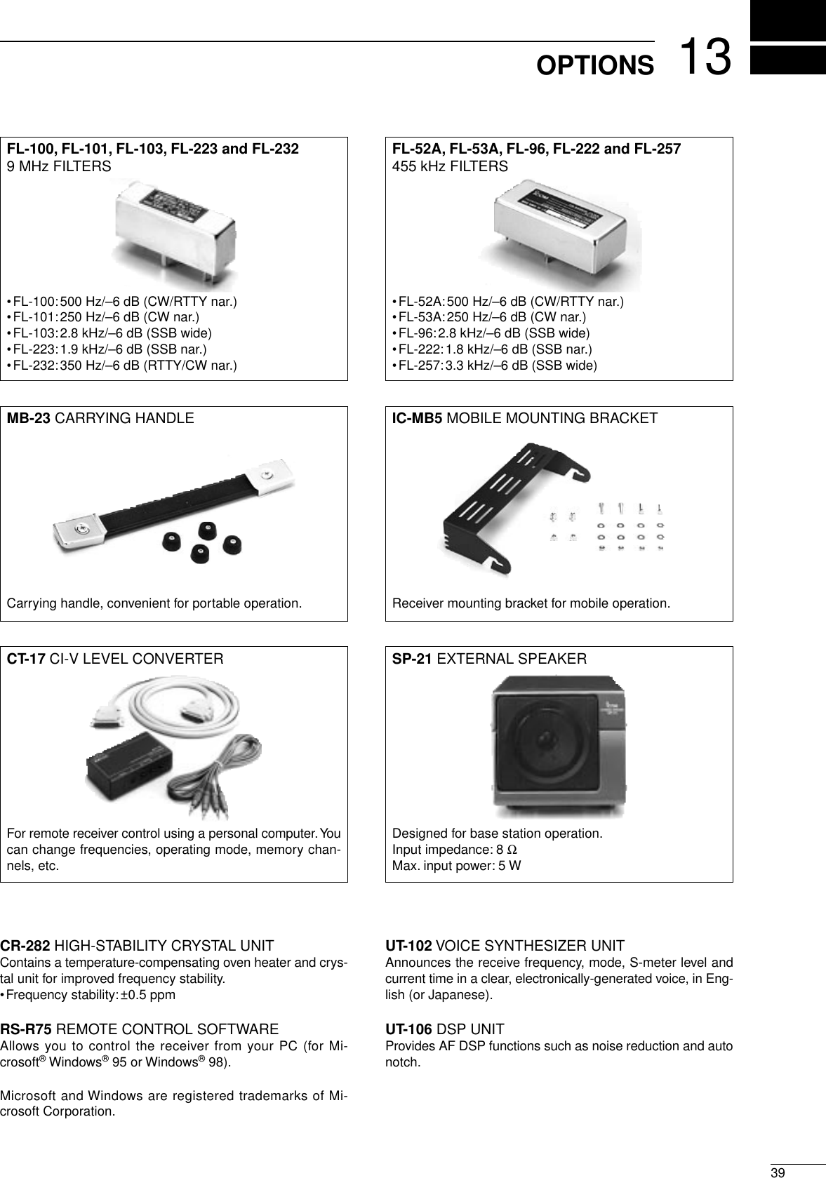
![■GroundingTo prevent accidents involving electricity and interfer-ence from transceivers, ground the receiver throughthe [GND] terminal on the rear panel.For best results, connect a heavy gauge wire or strapto a long earth-sunk copper rod. Make the distance be-tween the [GND] terminal and ground as short as pos-sible.RWARNING: NEVER connect the [GND]terminal to a gas or electric pipe, since the connec-tion could cause an explosion or electric shock.■Receiver standThe base of the receiver has an adjustable stand fordesktop use. Set the stand to one of two angles de-pending on your operating conditions.■Optional bracket andcarrying handleDMounting bracketAn optional IC-MB5 MOBILE MOUNTING BRACKET is avail-able to install the radio under a table, on a wall, in avehicle, etc.Select an area to mount the receiver keeping in mindthat the weight of the receiver is approx. 3 kg.DCarrying handleAn optional handle allows you to easily carry andtransport the receiver.Attach the MB-23 CARRYING HANDLE with the suppliedrubber feet as shown.37INSTALLATION AND CONNECTIONSFlat washer](https://usermanual.wiki/ICOM-orporated/IC-R75.manual/User-Guide-30547-Page-9.png)
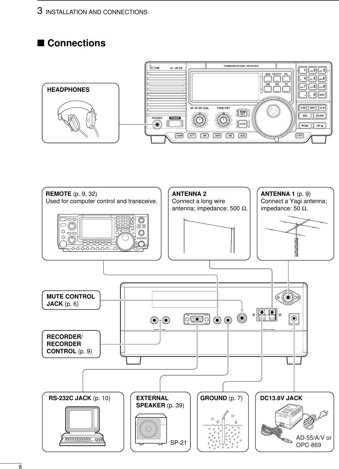
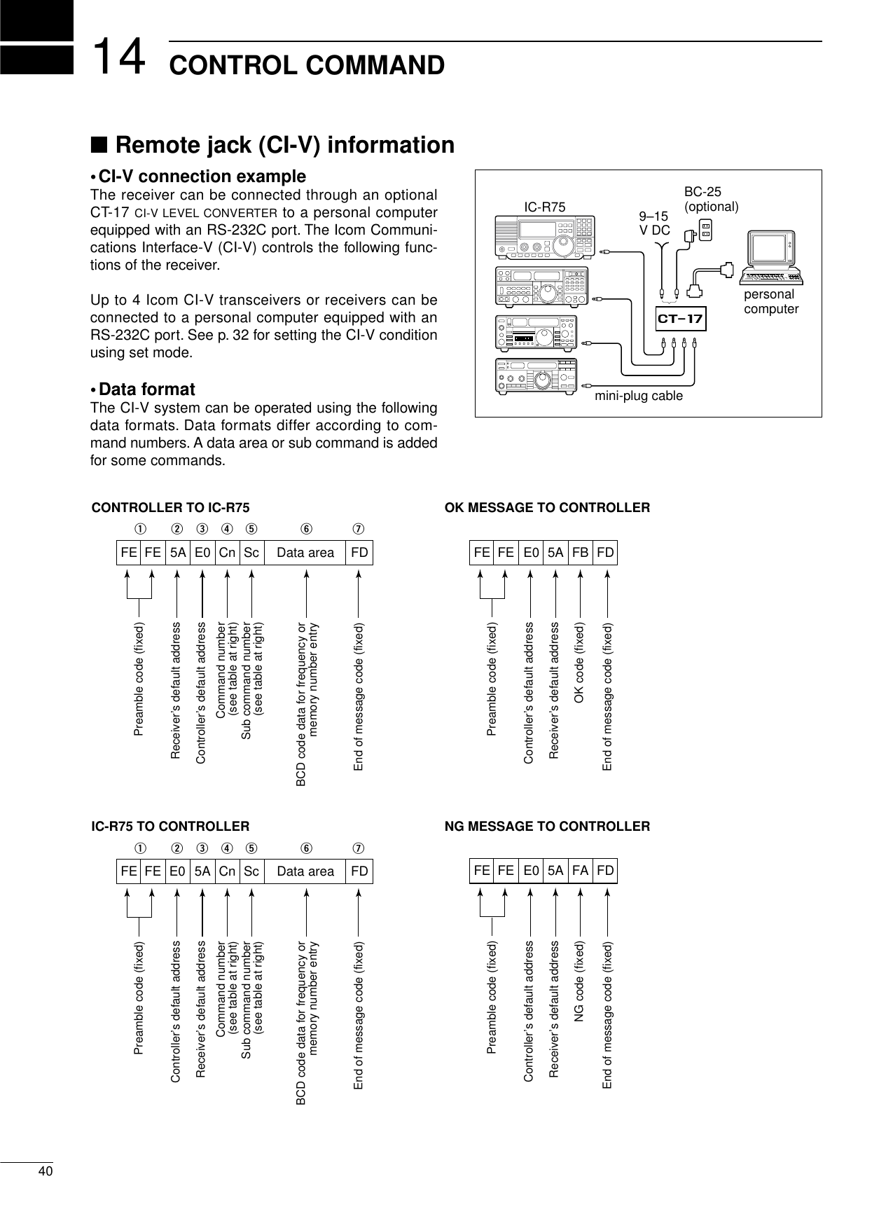
![■Tape recorder connections■Transceive function93INSTALLATION AND CONNECTIONSPL-259 CONNECTOR INSTALLATION EXAMPLE30 mm10 mm (soft solder)10 mm1–2 mmsolder solderSoftsolderCoupling ringSlide the coupling ring down. Strip the cable jacket and soft solder.Slide the connector body on and solder it.Screw the coupling ring onto the connector body.Strip the cable as shown at left. Soft solder the center con-ductor.(10 mm ≈ 3⁄8 in)qwer■Antenna connectionAntennas play a very important role in receiver opera-tion. Connecting a poor quality antenna to the receiverwill result in less than optimum performance.When using a 50 Ωantenna, use [ANT1] connector forconnection. When using a 500 Ωlong wire antenna,use [ANT2] terminal for connection.The [REC OUT] jack has 350 mV rms/4.7 kΩoutputfor connection to other audio equipment.[REC REMOTE] jack: Grounds when a signal is received and squelch opens. If a tape recorder has a control terminal, this jack can be used for recording control. (1 A/DC max.)[RECREMOTE] [REC OUT]350 mVrms4.7 kΩ[AUX IN] or[LINE IN] jackIC-R75Icom CI-V transceivers or receivers can be connectedvia the [REMOTE] jack. The frequency and mode be-come the same* when either radio is changed.*When a set frequency is out-of-range for one of the con-nected transceivers or receivers, the connected radio’s fre-quency/mode does not change.[REMOTE]IC-R75Icom CI-V transceiver/receiverConnect to [REMOTE] jackBe sure the “CIV TRn” item is turned ON in set mode (p. 32).](https://usermanual.wiki/ICOM-orporated/IC-R75.manual/User-Guide-30547-Page-11.png)
![103INSTALLATION AND CONNECTIONS■Connecting to a PCTo connect a terminal unit, TNC or scan converter,refer to the diagram below.qConnect a terminal unit as below.wSelect RTTY mode (or USB, CW modes for HFband data communications).eSet the receiver to the desired frequency as atright.rSet the connected terminal unit to the appropriatesettings.•Refer to the terminal unit’s instructions.The optional 250 Hz CW narrow filters may notpass RTTY signals. Be sure to select the appropri-ate IF filters corresponding to the signal width.(pgs. 18, 19)Frequency settings depend on the mode used.FM mode:[Setting frequency (displayed freq.)]= [Desiredfreq.]USB mode:[Setting frequency (displayed freq.)]= [Desiredfreq.]–[Center of Mark and Space freq.]CW narrow mode:[Setting frequency (displayed freq.)]= [Desiredfreq.]–[Center of Mark and Space freq.]+[600 Hz]LSB mode (for amateur RTTY):[Setting frequency (displayed freq.)]= [Desiredfreq.]+[Mark freq.]The RS-R75 remote control software is available toperform data setting and remote control of the re-ceiver.Refer to the diagram below for connection.DSystem requirementsTo use this program, the following hardware and soft-ware are required:•IBM PC compatible computer•An RS-232C serial port•Microsoft®Windows®95 or Microsoft®Windows®98•Intel i486DX4 processor or faster (Pentium®100MHz or faster recommended)•At least 16 MB RAM•At least 10 MB of hard disk space•At least 640 ×480 pixel, high color (16 bit) display■FSK and AFSK (SSTV) connectionsTU or TNCAF INSQUELCH INto [REC]to [REC REMOTE]2-conductor 3.5(d) plugsPersonal computerPersonal computer IC-R75Supplied RS-232C cable (OPC-743)](https://usermanual.wiki/ICOM-orporated/IC-R75.manual/User-Guide-30547-Page-12.png)
![411FREQUENCY SETTING■Read me firstThe receiver uses memory channels for storage of fre-quencies (as well as mode, tuning steps, etc.). Whenturning power OFF or changing memory channels, thepreviously displayed frequency cannot be recalled un-less it has been stored into a memory channel.Therefore, when you want to keep a displayed fre-quency for later recall, you must program it into amemory channel by pushing [MW] for 2 sec.See p. 22 for details.■Using the keypadqPush the numeral keys on the keypad to enter theMHz digits for the desired frequency.•If a key is mistakenly pushed, push [CLR] and startagain from the beginning.•When entering the same MHz digits as the displayedfrequency, this step can be skipped.wPush [•] on the keypad.ePush the numeral keys to enter the frequency digitsbelow 1 MHz.•If a key is mistakenly pushed, push [CLR] and startagain from the beginning.rPush [ENT] to set the input frequency.•When pushing [ENT] after entering the MHz digits, zerosare automatically entered for the kHz digits.BLANKBLANKS1 3 57920 40 60dBAGCANTUSB R XVFO1“BLANK” appears above the memory channel readout until [MW] is pushed for 2 sec.Push [MW] for 2 sec. after tuning.[EXAMPLE]: Setting the frequency using the keypad.USB R XUSBUSB R XUSB R X USB R XUSB R X USB R X R XUSB R XUSB R XUSB R X USB R XUSB R X USB R X USB R XUSB R X15JKL8TUV...0QZ5JKL8TUVUSB R X0QZ•To set to 28.00 MHz 2ABC8TUVENT5JKLENT•To set to 21.050 MHz 2ABC•To set to 850 kHz (0.850 MHz)ENTENT•To change 14.19075 to 14.850 MHz](https://usermanual.wiki/ICOM-orporated/IC-R75.manual/User-Guide-30547-Page-13.png)
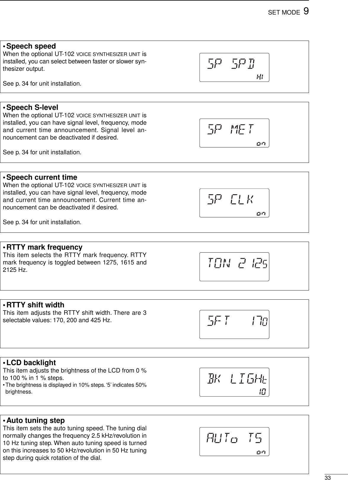
![124FREQUENCY SETTING■Frequency settingRotate the tuning dial to change the frequency.•The frequency changes in increments determined by theselected tuning step (see below).•When the lock function is activated (“LOCK” appears), thefrequency cannot be changed via tuning dial.Push [TS] one or more times to select a quick tuningstep.DProgrammable tuning stepsProgrammable tuning steps are available to suit youroperating requirements.These tuning steps are:•Independently selectable for each mode•Selectable from 0.1, 1, 5, 6.25, 9, 10, 12.5, 20, 25,100 kHzqSelect the desired operating mode with [SSB],[CW/RTTY], [AM] or [FM]. (p. 14)wPush [TS] one or more times until the programma-ble tuning step indicator, “6,” appears above the 1kHz.•Rotating the tuning dial changes the frequency accord-ing to the set tuning step.ePush [TS] for 2 sec. while the programmable tun-ing step indicator appears to enter the tuning stepset mode.rRotate the tuning dial to set the desired tuning stepfor the selected mode.tPush [TS] to exit the tuning step set mode.yRotate the tuning dial to change the frequency ac-cording to the set tuning step.D1 Hz and 10 Hz tuning stepsWhen both the 1 MHz tuning step and programmabletuning step, “6,” disappear, rotating the tuning dialchanges the frequency in increments of 1 or 10 Hz.qPush [TS] one or more times until the programma-ble tuning step indicator or 1 MHz tuning step in-dicator, “6,” disappears.wPush [TS] for 2 sec. to toggle between the 1 and10 Hz step settings.•When the 1 Hz step is selected, the 1 Hz digit appearsin the frequency indication; when the 10 Hz step is se-lected, the 1 Hz digit disappears from the frequency in-dication.USB R XBLANKBLANKS1 3 57920 40 60dBAGCANTVFO1Programmable tuningstep indicator10 kHz tuning step isselected.[TS]USB R XBLANKBLANKS1 3 57920 40 60dBAGCANTVFO1USB R XBLANKBLANKS1 3 57920 40 60dBAGCANTVFO1Rotating the tuning dialchanges the frequencyin 10 Hz steps.Rotating the tuning dialchanges the frequencyin 1 Hz steps.TSPush for 2 sec.](https://usermanual.wiki/ICOM-orporated/IC-R75.manual/User-Guide-30547-Page-14.png)
![134FREQUENCY SETTINGD1 MHz quick tuning stepThe quick tuning step function allows you to changethe frequency in 1 MHz steps when rotating the tun-ing dial.Push [TS] one or more times until the 1 MHz tuningstep indicator, “6,” appears above the 1 MHz indica-tor.USB R XBLANKBLANKS1 3 57920 40 60dBAGCANTVFO1Quick tuning step indicator10 Hz tuning1 Hz tuningmomentarily2 sec.2 sec.2 sec.1 MHz tuningProgrammable step tuning(100 Hz –100 kHz)Selectable for each mode.momentarilymomentarilyUSB R X USB R X USB R XUSB R X[TS] SWITCH FLOW CHART■Dial lock functionThe dial lock function prevents accidental changescaused by the tuning dial.The lock function electroni-cally locks the dial.Push [LOCK] momentarily to toggle the lock functionON and OFF.•“LOCK” appears in the function display while the lock func-tion is activated.USB R XBLANKBLANKS1 3 57920 40 60dBAGCANTVFO1LOCK“LOCK” appears while the lock function is activated.[LOCK]](https://usermanual.wiki/ICOM-orporated/IC-R75.manual/User-Guide-30547-Page-15.png)
![514RECEIVE FUNCTIONS■Mode selectionThe following modes are available in the IC-R75:SSB (LSB/USB), CW, CW REV (CW reverse), FM,AM, S-AM (Synchronous detection AM), RTTY andRTTY REV (RTTY reverse).➥Push [SSB] to toggle between LSB and USB.➥Push [CW/RTTY] momentarily to toggle betweenCW and RTTY.➥Push [CW/RTTY] for 2 sec. to toggle between CWand CW reverse or RTTY and RTTY reverse.➥Push [AM] to toggle between AM and S-AM.•“S-” blinks when automatic mode selection betweenS-AM and AM modes is in use. This can be set in setmode. (p. 31)➥Push [FM] to select FM.The selected mode is indicated in the function dis-play.OPERATING MODE SELECTIONSSBAMPush momentarilyFMCW/RTTYCW CW REV RTTY RTTY REVAMPush mode switch for 2 sec. Push mode switchmomentarily.S-AMFMLSB USB■Squelch and RF gainThe receiver uses the same control, [RF/SQL], to ad-just one of either the RF gain or the squelch.[RF/SQL] adjusts either the RF gain or the squelchdepending on the operating mode selected and thecondition of the RF/SQL item in set mode (p. 30).•[RF/SQL] control priority* The RF gain is set to maximum level when the [RF/SQL]is set as [SQL] control.The RF (Radio Frequency) gain is used to adjust thereceiver gain.•Shallow rotation moves the S-meter to the right indicatingthe signal strength which can be received.The recommended position for RF gain is the 12o’clock position since this sets RF gain to the max.The SQUELCH removes noise output from thespeaker (closed condition) when no signal is re-ceived. The squelch is particularly effective for FM. Itis also available for the other modes.•When operating in FM, first rotate the control fully counter-clockwise. Then, rotate the control clockwise to the pointwhere the noise just disappears. This is the best position.The squelch does not open for weak signals when it is settoo deep.•A segment appears in the S-meter to indicate the S-metersquelch level.•When set as the [RF/SQL] controlSet modesetting USB, LSB,CW, RTTY AM, S-AM, FMSq (SQL) SQL* SQL*At (AUTO) RF GAIN SQL*rS (RF/SQL) RF/SQL RF/SQLRecommended levelMinimum RF gainAdjustable rangeRF gain adjustablerangeMaximum RF gainMaximum RF gainSquelch is open. S-meter squelchS-meter squelchthresholdNoise squelch threshold (FM mode)Shallow DeepSquelch is open.S-meter squelchNoise squelch (FM mode)Noise squelch (FM mode)•When set as the [SQL] control•When set as the [RF] control](https://usermanual.wiki/ICOM-orporated/IC-R75.manual/User-Guide-30547-Page-16.png)
![155RECEIVE FUNCTIONS■Twin PBT operationThe twin PBT (Passband Tuning) function electroni-cally narrows the IF passband widths to reduce inter-ference. Moving both [TWIN PBT] controls to thesame position shifts the IF.Variable range depends on the filter selection. ±1.29kHz in 15 Hz steps and ±258 kHz in 3 Hz steps areavailable.PBT OPERATION EXAMPLE•[TWIN PBT] should normally be set to the centerpositions when there is no interference.•When PBT is used, the audio tone may bechanged.•PBT may not function with some IF filter combina-tions.•Not available for FM mode.TWIN PBT TWIN PBTTWIN PBTIF center frequency Interference Desired signalPassbandBoth controls at center position Cutting a lower passband Cutting both higher and lower passbandsInterference InterferenceDesired signalPassband■Noise blankerThe noise blanker eliminates pulse-type noise suchas from car ignitions. The noise blanker is not avail-able for FM mode.➥Push the [NB] switch to turn the noise blanker ONor OFF.•When using the noise blanker, received signalsmay be distorted if they are excessively strong.•The noise blanker function in AM mode can bedeactivated depending on set mode setting. (p.31)[NB]](https://usermanual.wiki/ICOM-orporated/IC-R75.manual/User-Guide-30547-Page-17.png)
![165RECEIVE FUNCTIONS■Preamp The preamp amplifies received signals in the frontend circuit to improve the S/N ratio and sensitivity.Turn this function ON when receiving weak signals.➥Push [P.AMP] to toggle between preamp-1 andpreamp-2 or turn the preamp OFF.■AttenuatorThe attenuator prevents desired signals from distort-ing when very strong signals are near the desired fre-quency or when very strong electric fields, such asfrom broadcasting stations, are near your location.➥Push [ATT] toggle the 20 dB attenuator functionON and OFF.•“ATT” appears when the attenuator is turned ON.■AGC time constantThe AGC (Automatic Gain Control) controls receivergain to produce a constant audio output level evenwhen the received signal strength is varied by fading,etc. Use AGC slow for normal phone operation; AGCfast for receiving data and searching for signals.➥Push [AGC] momentary to toggle the AGC timeconstant between fast and slow.•“F.AGC” appears when the fast time constant is se-lected.•“AGC” appears when the slow time constant is se-lected.➥Push [AGC] for 2 sec. to turn the AGC circuit OFF.•“AGC OFF” appears when the AGC circuit is turnedOFF.•Push [AGC] to turn the AGC circuit ON.USB R XBLANKBLANKS1 3 57920 40 60dBAGCANTVFO1PREAMP 1“PREAMP” appears while the preamp is activated.■Antenna selection2 types of antenna can be connected to this receiver.When 2 antennas are connected, select an antennadepending on the operating condition.➥Push [ANT(SET)] for 2 sec. to toggle between theantenna 1 and 2 connectors.•If a blank memory channel has been selected, push[V/M] to select VFO mode in advance.USB R XBLANKBLANKS1 3 57920 40 60dBAGCANTVFO1“ANT1” appears when the [ANT1] connector is in use.USB R XBLANKBLANKS1 3 57920 40 60dBAGCANTVFO1ATT“ATT” appears while the attenuatoris activated.USB R XBLANKBLANKS1 3 57920 40 60dBAGCANTVFO1F.AGC“F.AGC” appears when the fast time constant is selected.](https://usermanual.wiki/ICOM-orporated/IC-R75.manual/User-Guide-30547-Page-18.png)
![175RECEIVE FUNCTIONS■CW reverse modeCW-R (CW Reverse) mode receives CW signals witha reverse side CW carrier point like that of LSB andUSB modes.Use when interfering signals are near a desired signaland you want to change the interference tone.qPush [CW/RTTY] once or twice to select CWmode.wPush [CW/RTTY] for 2 sec. to toggle between CWand CW reverse (CW REV).•Check the interfering tone.•Receive audio tone response■RTTY reverse modeReceived characters are occasionally garbled whenthe receive signal is reversed between MARK andSPACE.This reversal can be caused by incorrect TNCconnections, settings, commands, etc.To receive a reversed RTTY signal correctly, selectRTTY reverse mode.qPush [CW/RTTY] once or twice to select RTTYmode.wPush [CW/RTTY] for 2 sec. to toggle betweenRTTY and RTTY reverse (RTTY REV).•Check the receive signal.■CW pitch controlThe received CW audio pitch and monitored CWaudio can be adjusted to suit your preferences (300to 900 Hz) without changing the operating frequency.The received CW audio pitch can be adjusted in 10Hz steps.qPush [(ANT)SET] momentarily to enter set mode.wPush [UPY] or [ZDN] to select the ‘CW PITCH’item.eRotate the tuning dial to set the desired CW audiopitch.•CW audio pitch is displayed in 10 Hz steps. ‘60’ indi-cates 600 Hz CW audio pitch.rPush [(ANT)SET] again to exit set mode.BFO1/3 octavePush for 2 sec.Desired signal(600 Hz)CW mode (USB side)Interference(800 Hz)BFO1/2 octaveDesired signal(600 Hz)CW REV mode (LSB side)Interference(400 Hz)CW/RTTYShows a 600 Hz CW audio pitch](https://usermanual.wiki/ICOM-orporated/IC-R75.manual/User-Guide-30547-Page-19.png)
![185RECEIVE FUNCTIONS■Filter selectionThe filter selection switches the IF passband width asshown in the table at right.The filter selection is automatically memorized ineach mode.qSelect the desired mode with the mode switches.wPush [FIL] one or more times to select the desiredfilter combination.•ãor çdoes not appear while in normal IF filter.•çappears when wide IF filters are selected.•ãappears when narrow IF filters are selected.When an optional filter is installed, set the optionalfilter in filter set mode. Optional filters are not se-lected by default.•Filter constructionCFWS450E (15 kHz)CFWS450HT (6 kHz)FL-65 (2.4 kHz)FL-257 (3.3 kHz)FL-96 (2.8 kHz)FL-222 (1.8 kHz)FL-52A (500 Hz)FL-53A (250 Hz)optionalFL-23 (15 kHz)FL-272 (2.4 kHz)FL-103 (2.8 kHz)FL-223 (1.9 kHz)FL-100 (500 Hz)FL-232 (350 Hz)FL-101 (250 Hz)optionalMixer2nd IF signal 3rd IF signal9 MHz IF filter 455 kHz IF filterIF Filter Passbandwidth Recommendedselectivity9 MHzFL-100 500 Hz/–6 dB CW-N, RTTY-NFL-101 250 Hz/–6 dBFL-103 2.8 kHz/–6 dB SSB-WCW-NFL-223 1.9 kHz/–6 dB SSB-N455 kHzFL-52A 500 Hz/–6 dB CW-N, RTTY-NFL-53A 250 Hz/–6 dB CW-NFL-96 2.8 kHz/–6 dB SSB-WFL-232 350 Hz/–6 dB CW-N, RTTY-NFL-222 1.8 kHz/–6 dB SSB-NFL-257 3.3 kHz/–6 dB SSB-W](https://usermanual.wiki/ICOM-orporated/IC-R75.manual/User-Guide-30547-Page-20.png)
![195RECEIVE FUNCTIONS■Filter set modeWhen an optional filter is installed, set the optional fil-ters in filter set mode. Optional filters are not selectedby default.DOptional filter settingqPush [FIL] for 2 sec. to enter filter set mode.•If a blank memory channel has been selected, push[V/M] to select VFO mode in advance.wPush [UPY] or [ZDN] one or more times until“oP1” appears for 9 MHz IF filter setting or “oP2”appears for 455 kHz IF filter setting.eRotate the tuning dial to select the installed filter.•“No,” “100,” “101,” “103,” “223” and “232” indicate no op-tional filter, FL-100, FL-101, FL-103, FL-223 andFL-232, respectively for 9 MHz IF filter selection.•“No,” “52A,” “53A,” “96,” “222” and “257” indicate no op-tional filter, FL-52A, FL-53A, FL-96, FL-222 andFL-257, respectively for 455 kHz IF filter selection.rPush [FIL] to exit filter set mode.DWide/narrow filter settingqPush [FIL] for 2 sec. to enter filter set mode.•If a blank memory channel has been selected, push[V/M] to select VFO mode in advance.wSelect the desired mode with the mode switches.ePush [UPY] or [ZDN] one or more times to selectthe desired width 9 MHz or 455 kHz IF filter.•Wide or narrow mode can be deactivated when 9 MHzwide or narrow filter is set to ‘OFF.’•455 kHz wide or narrow filter selection does appearwhen 9 MHz wide or narrow filter is set to ‘OFF.’rRotate the tuning dial to select a filter.tRepeat steps wand rto select IF filters for othermodes, if desired.•The filter combinations are stored depending on oper-ating modes.yPush [FIL] to exit filter set mode.DExpanded filter selection ON/OFFThe selectable filter combinations can be expandedby setting the expanded filter selection to ON.qPush [FIL] for 2 sec. to enter filter set mode.•If a blank memory channel has been selected, push[V/M] to select VFO mode in advance.wPush [UPY] or [ZDN] one or more times until“EXP” appears.eRotate the tuning dial to turn the expanded filterselection ON/OFF.•If ‘ON’ is selected, the expanded filter selection can beused.rPush [FIL] to exit filter set mode.*455 kHz wide or narrow filter selection does ap-pear when 9 MHz wide or narrow filter is set to‘OFF.’USBWUSBWUSBNUSBUSBUSBNUSBUSBUSB•9 MHz normal filter selection•455 kHz normal filter selection•9 MHz narrow filter selection•455 kHz narrow filter selection*•9 MHz wide filter selection•455 kHz wide filter selection*•Expanded filter selection ON/OFF•9 MHz normal filter selection•455 kHz normal filter selection](https://usermanual.wiki/ICOM-orporated/IC-R75.manual/User-Guide-30547-Page-21.png)
![205RECEIVE FUNCTIONS■Optional auto notch functionWhen an optional UT-106 is installed (DSP appearsin the function display), an auto notch function can beused.The function automatically attenuates more than 3beat tones, tuning signals, etc., even if they are mov-ing.The auto notch functions in SSB mode only.qSelect SSB mode.wPush [ANF] to turn the auto notch function ON.•[ANF] indicator appears.ePush [ANF] again to cancel the function.•[ANF] indicator disappears.Unwanted tone frequencyDesired signal (AF) Desired signal (AF)Particular frequencyis attenuatedAuto notch OFF Auto notch ONoptional UT-106■Optional noise reduction functionWhen an optional UT-106 is installed (DSP appearsin the function display), noise reduction function canbe used.The noise reduction function reduces noise compo-nents and picks out desired signals which are buriedin noise. The received AF signals are converted todigital signals and then the desired signals are sepa-rated from the noise.qPush [NR] to turn the noise reduction ON.•[NR] indicator appears.wPush [NR] for 2 sec. to enter the noise reductionlevel setting condition.eRotate the tuning dial to adjust the noise reductionlevel.rPush [NR] to exit the setting condition.tPush [NR] again to turn the noise reduction OFF.•[NR] indicator disappears.•Noise reduction exampleGreater setting of the [NR] level results in audiosignal masking or distortion. Set the [NR] level formaximum readability. The noise reduction functionis not available in AM and FM modes.Noise reduction OFF Noise reduction activatedDesired signal (CW)Noise componentsoptional UT-106](https://usermanual.wiki/ICOM-orporated/IC-R75.manual/User-Guide-30547-Page-22.png)
![■Memory channelsThe receiver has 101 memory channels. The memorymode is very useful for quickly changing to often-usedfrequencies.All 101 memory channels are tuneable which meansthe programmed frequency can be tuned temporarilywith the tuning dial, etc. in memory mode.■Memory channel selection621MEMORY OPERATIONMEMORYCHANNELMEMORYCHANNELNUMBER CAPABILITY TRANSFERTO VFO OVER-WRITING CLEARRegular memorychannels 1–99 One frequency and one mode ineach memory channel. Yes Yes YesScan edgememorychannels P1, P2 One frequency and one mode ineach memory channel as scanedges for programmed scan. Yes Yes NoDUsing the [UPY] or [ZDN] keysqPush [V/M] to select memory mode.•“MEMO” appears.wPush [UPY] or [ZDN] several times to select thedesired memory channel.•Push and hold [UPY] or [ZDN] for continuous selec-tion.eTo return to VFO mode, push [V/M] again.DUsing the keypadqPush [V/M] to select memory mode.•“MEMO” appears.wPush the desired memory channel number usingthe keypad.•Enter 100 or 101 to select scan edge channel P1 or P2,respectively.ePush [V/M] to select the desired memory channel.rTo return to VFO mode, push [V/M] again.USB R XS1 3 57920 40 60dBAGCANTMEMO1USB R XS1 3 57920 40 60dBAGCANTMEMO1USB R XS1 3 57920 40 60dBAGCANTVFO1UP DNorV/MUSB R XS1 3 57920 40 60dBAGCANTMEMO1USB R XS1 3 57920 40 60dBAGCANTMEMO1USB R XS1 3 57920 40 60dBAGCANTVFO11 2ABCV/MV/M](https://usermanual.wiki/ICOM-orporated/IC-R75.manual/User-Guide-30547-Page-23.png)
![Memory channel programming can be preformed ei-ther in VFO mode or in memory mode.■Memory channel programming226MEMORY OPERATIONDProgramming in memory modeqSelect the desired memory channel with [UPY] or[ZDN] in memory mode.•“BLANK” appears if the selected memory channel is ablank channel (and does not have contents).wSet the desired frequency and operating mode inmemory mode.•To program a blank channel, use direct frequency entrywith the keypad in advance.ePush [MW] for 2 sec. to program the displayed fre-quency and operating mode into the memorychannel.•Preamp setting, attenuator on/off, antenna selection,and AGC setting can also be programmed into a mem-ory channel.[EXAMPLE]: Programming 21.280 MHz/CW intomemory channel 18.DProgramming in VFO modeqSet the desired frequency and operating mode inVFO mode.wPush [UPY] or [ZDN] several times to select thedesired memory channel.•“BLANK” appears if the selected memory channel is ablank channel (and does not have contents).ePush [MW] for 2 sec. to program the displayed fre-quency and operating mode into the memorychannel.•Preamp setting, attenuator on/off, antenna selection,and AGC setting can also be programmed into a mem-ory channel.[EXAMPLE]: Programming 7.088 MHz/LSB intomemory channel 12.R XS1 3 57920 40 60dBAGCANT 1USB R XS1 3 57920 40 60dBAGCANTVFOVFO1MWLSBR XS1 3 57920 40 60dBAGCANT 1VFOLSBBLANKBLANKR XS1 3 57920 40 60dBAGCANT 1VFOLSBUP DNorPush for 2 sec.or keypadBeep Beep BeepSSBS1 3 57920 40 60dBUSB R XS1 3 57920 40 60dBAGCANTVFO1MWR XS1 3 57920 40 60dBAGCANT 1 BLANKBLANKV/MBLANKBLANKMEMOCW/RTTYR XCWR XS1 3 57920 40 60dBAGCANT 1R XCWMEMOMEMOUP DNorthenthenPush for 2 sec.keypadBeep Beep Beep](https://usermanual.wiki/ICOM-orporated/IC-R75.manual/User-Guide-30547-Page-24.png)
![■Frequency transferringThe frequency and operating mode in a memory chan-nel can be transferred to the VFO. Frequency transferring can be performed in either VFOmode or memory mode.236MEMORY OPERATIONDTransferring in memory modeThis is useful for transferring frequency and operatingmode while operating in memory mode.When you have changed the frequency or operat-ing mode in the selected memory channel:•Displayed frequency and mode are transferred.•Programmed frequency and mode in the mem-ory channel are not transferred, and they remainin the memory channel.qSelect the memory channel to be transferred with[UPY] or [ZDN] in memory mode.•And, set the frequency or operating mode if required.wPush [V/M] for 2 sec. to transfer the frequency andoperating mode.•Displayed frequency and operating mode are trans-ferred to the VFO.eTo return to VFO mode, push [V/M] momentarily.TRANSFERRING EXAMPLE IN MEMORY MODEOperating frequency : 14.020 MHz/CW (M-ch 16)Contents of M-ch 16 : 14.018 MHz/CWDTransferring in VFO modeThis is useful for transferring programmed contents toVFO.qSelect VFO mode with [V/M].wSelect the memory channel to be transferred with[UPY] or [ZDN].•“BLANK” appears if the selected memory channel is ablank channel (and does not have contents).ePush [V/M] for 2 sec. to transfer the frequency andoperating mode.•Transferred frequency and operating mode appear onthe frequency readout.TRANSFERRING EXAMPLE IN VFO MODEOperating frequency : 21.320 MHz/USB (VFO)Contents of M-ch 16 : 14.018 MHz/CWS1 3 57920 40 60dBAGCANT 1VFOV/MR XS1 3 57920 40 60dBAGCANTVFO1CWS1 3 57920 40 60dBAGCANTVFO1USB R XUSB R XUP DNorPush for 2 sec.Beep Beep BeepS1 3 57920 40 60dBAGCANT 1V/MR XS1 3 57920 40 60dBAGCANTVFO1CWS1 3 57920 40 60dBAGCANT 1R XR XV/MCWCWMEMOMEMOV/MS1 3 57920 40 60dBAGCANT 1R XCWMEMOPush for 2 sec.Displayed memory channel contents are transferred.Memory channel contents remain in the memory channel.Beep Beep Beep](https://usermanual.wiki/ICOM-orporated/IC-R75.manual/User-Guide-30547-Page-25.png)
![■Memory clearing■Memory names246MEMORY OPERATIONAll memory channels (including scan edges) can betagged with alphanumeric names of up to 8 charac-ters each.Letters (capitals except ‘o’), numerals and spaces canbe used. Numerals can only be used for the 7th and8th digits.DTurning memory name indicationON/OFFqSelect memory mode with [V/M].wPush [SEL] for 2 sec. to turn memory name indi-cation ON.•Frequency disappears and a memory name appears ifprogrammed.ePush [SEL] for 2 sec. to turn memory name indi-cation OFF.While the memory name indication is selected,pushing [TS] shows the operating frequency; androtating the tuning dial while pushing [TS] changesthe frequency temporally.DEditing (programming) memory namesqSelect memory mode with [V/M].wPush [SEL] for 2 sec. to turn memory name indi-cation ON.eSelect the memory channel to program with [UPY]or [ZDN].•“BLANK” appears if the selected memory channel is ablank channel (and does not have contents).rPush [ENT] to edit memory channel name.•A cursor appears and blinks.•Memory channel names of blank channels cannot beedited.tInput the desired character by pushing a key onthe keypad one or more times.•[1] inputs numeral 1.•[2] inputs numeral 2 and letters A to C.•[3] inputs numeral 3 and letters D to F.•[4] inputs numeral 4 and letters G to I.•[5] inputs numeral 5 and letters J to L.•[6] inputs numeral 6 and letters M to O.•[7] inputs numeral 7 and letters P, R and S.•[8] inputs numeral 8 and letters T to V.•[9] inputs numeral 9 and letters W to Y.•[0] inputs numeral 0 and letters Q and Z.•Rotate tuning dial for cursor movement.•Numerals can only be used for the 7th and 8th digits.•Push [•] to delete the selected character and input aspace.yPush [ENT] to input the set the name.•The cursor disappears.•Push [CLR] to abandon the settings and return to pre-vious memory name.uRepeat steps eto yto program another memorychannel’s name, if desired.iPush [SEL] for 2 sec. to turn memory name indi-cation OFF.Any unnecessary memory channels can be cleared.The cleared memory channels become blank chan-nels.qSelect memory mode with [V/M].wSelect the memory channel to be cleared with[UPY] or [ZDN].ePush [CLR] for 2 sec. to clear the contents.•The programmed frequency and operating mode dis-appear.•“BLANK” appears.rTo clear other memory channels, repeat steps wand e.S1 3 57920 40 60dBS1 3 57920 40 60dBAGCANT 1USB R XCLRBLANKBLANKMEMOMEMOPush for 2 sec.Beep Beep BeepS1 3 57920 40 60dBAGCANT 1USB R XMEMONon-named channelS1 3 57920 40 60dBAGCANT 1USB R XMEMOS1 3 57920 40 60dBAGCANT 1USB R XMEMO](https://usermanual.wiki/ICOM-orporated/IC-R75.manual/User-Guide-30547-Page-26.png)
![■Scan types725SCANS■Preparation•ChannelsFor programmed scan/auto memory write scan:Program scan edge frequencies into scan edge mem-ory channels P1 and P2.For memory scan:Program 2 or more memory channels except scanedge memory channels.For select memory scan:Designate 2 or more memory channels as select mem-ory channels. To designate the channel as a selectmemory channel, select a memory channel, then push[SEL] in the scan screen (memory mode) or in thememory channel screen.For priority watch:Program 1 or more memory channels.•Scan resume ON/OFFYou can select the scan to resume or cancel when de-tecting a signal, in set mode. Scan resume ON/OFFmust be set before operating a scan. See p. 31 forON/OFF setting and scan resume condition details.•Scan speedScan speed can be selected from 2 levels, high or low,in set mode. See p. 31 for details.•Squelch conditionPROGRAMMED SCAN/AUTO MEMORY WRITE SCANRepeatedly scans between two scan edge frequencies (scan edge memory channels P1 and P2). Auto memory write scan automatically memorizes paused frequencies into memory channels 80 to 99.This scan operates in VFO mode.PRIORITY WATCHRepeatedly watches a memory channel.This scan operates in memory mode. This scan operates in VFO mode.ScanScan edge P1 or P2 Scan edge P2 or P1JumpThis scan operates in memory mode.MEMORY SCANRepeatedly scans all programmed memory channels.Mch 1 Mch 5Mch 2 Mch 3 Mch 4Mch 6Mch 7Mch 99BLANKS (select)S (select) S (select)S (select)S (select)SELECT MEMORY SCANRepeatedly scans all select memory channels.Mch 1 Mch 5Mch 2 Mch 3 Mch 4Mch 6Mch 7Mch 99BLANKS (select)S (select) S (select)S (select)S (select) VFOfrequency Memorychannel5 sec.125 msec.ScanstartwithProgrammed scan/auto memory writescan Memory scanSquelchopenThe scan continuesuntil it is stopped man-ually, and does notpause even if it detectssignals.Scan pauses oneach channel whenthe scan resume isON; not applicablewhen OFF.Squelchopenclosed Scan stops when detecting a signal.If you set scan resume ON in set mode, thescan pauses for 10 sec. when detecting a sig-nal, then resumes. When a signal disappearswhile scan is paused, scan resumes 2 sec.later.](https://usermanual.wiki/ICOM-orporated/IC-R75.manual/User-Guide-30547-Page-27.png)
![267SCANS■Programmed scan operationqSelect VFO mode with [V/M].wSelect the desired operating mode.•The operating mode can also be changed while scan-ning.eSet [RF/SQL] open or closed.•See previous page for scan condition.•If the [RF/SQL] control function is set as RF control, thesquelch always opens. See pgs. 14, 30 for details.rPush [SCAN] to start the programmed scan.•“SCAN” appears while scanning.tWhen the scan detects a signal, the scan stops,pauses or ignores it depending on the resume set-ting and the squelch condition.yTo cancel the scan, push [SCAN].If the same frequencies are programmed into thescan edge memory channel P1 and P2, pro-grammed scan does not start.USB R XS1 3 57920 40 60dBAGCANT 1SCANVFO■Memory/select memory scan operationqSelect memory mode with [V/M].wSelect the desired operating mode.•The operating mode can also be changed while scan-ning.eSet [RF/SQL] open or closed.•See previous page for scan condition.•If the [RF/SQL] control function is set as RF control, thesquelch always opens. See pgs. 14, 30 for details.rPush [SCAN] to start the memory/select memoryscan.•“SCAN” appears while scanning.tWhen the scan detects a signal, the scan stops,pauses or ignores it depending on the resume set-ting and the squelch condition.yTo cancel the scan, push [SCAN].2 or more memory channels must be programmedfor memory scan to start.USB R XS1 3 57920 40 60dBAGCANTMEMO1SCANS■Setting select memory channelsqSelect memory mode with [V/M].wSelect the desired memory channel to set as se-lect memory channel.ePush [SEL] to set the memory channel as a selectmemory or not.•“S” appears for select memory channels.rRepeat steps wto eto program another memorychannel as a select memory channel, if desired.USB R XS1 3 57920 40 60dBAGCANTMEMO1S“S” appears for the select channel.](https://usermanual.wiki/ICOM-orporated/IC-R75.manual/User-Guide-30547-Page-28.png)
![277SCANS■Priority watch operationPriority watch checks for signals on a frequency every5 sec. while operating on a VFO frequency.qSelect memory mode with [V/M].wSelect the desired memory channel to be watchedwith [UPY] or [ZDN].eSelect VFO mode.rSet [RF/SQL] closed.•If the [RF/SQL] control function is set as RF control, thesquelch always opens. See pgs. 14, 30 for details.tPush [SCAN] for 2 sec. to start priority watch.•“SCAN” appears.yWhen a signal is received on a watch channel, thefunction display shows the watch channel and“SCAN” blinks.uTo cancel the watch, push [SCAN].USBS1 3 57920 40 60dBAGCANT 1SCANVFOUSBS1 3 57920 40 60dBAGCANT 1SCANR XMEMO■Auto memory write scanAuto memory write scan operates in the same way asprogrammed scan. However, when a signal is re-ceived, the received frequency is automatically writ-ten into memory channels (80 to 99).When the auto memory write scan starts, the pre-viously written memory channels (80 to 99) arecleared.qSelect VFO mode with [V/M].wSelect the desired operating mode.•The operating mode can also be changed while scan-ning.eSet [RF/SQL] closed.•If the [RF/SQL] control function is set as RF control, thesquelch always opens. See pgs. 14, 30 for details.rPush [SCAN] to start the programmed scan.•“SCAN” appears while scanning.•If the same frequencies are programmed into the scanedge memory channel P1 and P2, programmed scandoes not start.tPush [MW] to start the auto memory write scan.•“80” blinks when auto memory write scan starts.yWhen the scan detects a signal, the frequency isprogrammed into a memory channel (80 to 99),starting from channel 80.uTo cancel the scan, push [SCAN].8081828384•••989914.456.0014.567.0014.678.0014.890.0014.050.00----------------------------USB R XS1 3 57920 40 60dBAGCANT 1SCANVFOBLANKBLANK](https://usermanual.wiki/ICOM-orporated/IC-R75.manual/User-Guide-30547-Page-29.png)
![■Setting the current timeThe receiver has a built-in 24-hour clock with power-off and power-on timer functions. This is useful whenlogging SWL’s, BCL’s and so on.qPush [CLOCK] to select clock indication mode.•Current time and “CL” appear.wPush [(ANT)SET] for 2 sec. to enter time settingcondition.•Current time flashes.eSet the current time using the tuning dial; or pushkeypad using 4-digit 24 hour system.rPush [ENT] to set the time.•Push [CLR] to cancel the setting.tPush [CLOCK] to exit clock indication mode.828CLOCK AND TIMERS■Setting power-on timeThe receiver can be set to turn ON automatically at aspecified time.qPush [CLOCK] to select clock indication mode.wPush [UPY] to select power-on timer screen.•Power-on time and “on” appear.ePush [(ANT)SET] for 2 sec. to enter time settingcondition.•Power-on time flashes.•Push [(ANT)SET] momentarily when the power-on timeris already turned ON.rSet the desired time using the tuning dial; or pushkeypad using 4-digit 24 hour system.tPush [ENT] to set the time.•Power-on timer is automatically turned ON.•Push [CLR] to cancel the setting.yPush [(ANT)SET] momentarily to toggle the power-on timer ON and OFF, if necessary.•“o” and “X” indicates the power-on timer is turned ONand OFF, respectively.uPush [ENT] to exit clock indication mode.iPush [POWER] for 2 sec. to turn the power OFF.•When the set time arrives, the power is automaticallyturned ON.TIMER](https://usermanual.wiki/ICOM-orporated/IC-R75.manual/User-Guide-30547-Page-30.png)
![298CLOCK AND TIMERS■Setting power-off timeThe receiver can be set to turn OFF automatically at aspecified time.qPush [CLOCK] to select clock indication mode.wPush [UPY] or [ZDN] twice to select power-offtimer screen.•Power-off time and “oF” appear.ePush [(ANT)SET] for 2 sec. to enter time settingcondition.•Power-off time flashes.•Push [(ANT)SET] momentarily when the power-off timeris already turned ON.rSet the desired time using the tuning dial; or pushkeypad using 4-digit 24 hour system.tPush [ENT] to set the time.•Power-off timer is automatically turned ON.•Push [CLR] to cancel the setting.yPush [(ANT)SET] momentarily to toggle the power-off timer ON and OFF, if necessary.•“o” and “X” indicates the power-off timer is turned ONand OFF, respectively.uPush [ENT] to exit clock indication mode.•When the set time arrives, the power is automaticallyturned OFF with 5 beeps.TIMER■Setting sleep timer periodThe receiver can be set to turn OFF automatically.The power-off period can be set from 1 min. to 23hours 59 min.qPush [CLOCK] to select clock indication mode.wPush [ZDN] to select sleep timer screen.•Sleep timer period and “SL” appear.ePush [(ANT)SET] for 2 sec. to enter time settingcondition.•Sleep timer period flashes.rSet the desired periods using the tuning dial; orpush keypad using 4-digit 24 hour system.tPush [ENT] to set the periods.•Sleep timer is automatically turned ON.•Push [CLR] to cancel the setting.yPush [(ANT)SET] momentarily to toggle the sleeptimer ON or OFF, if necessary.•“o” and “X” indicates the sleep timer is turned ON andOFF, respectively.uPush [ENT] to exit clock indication mode.iThe receiver emits 5 beeps and turns OFF afterthe sleep timer period elapses.TIMER](https://usermanual.wiki/ICOM-orporated/IC-R75.manual/User-Guide-30547-Page-31.png)
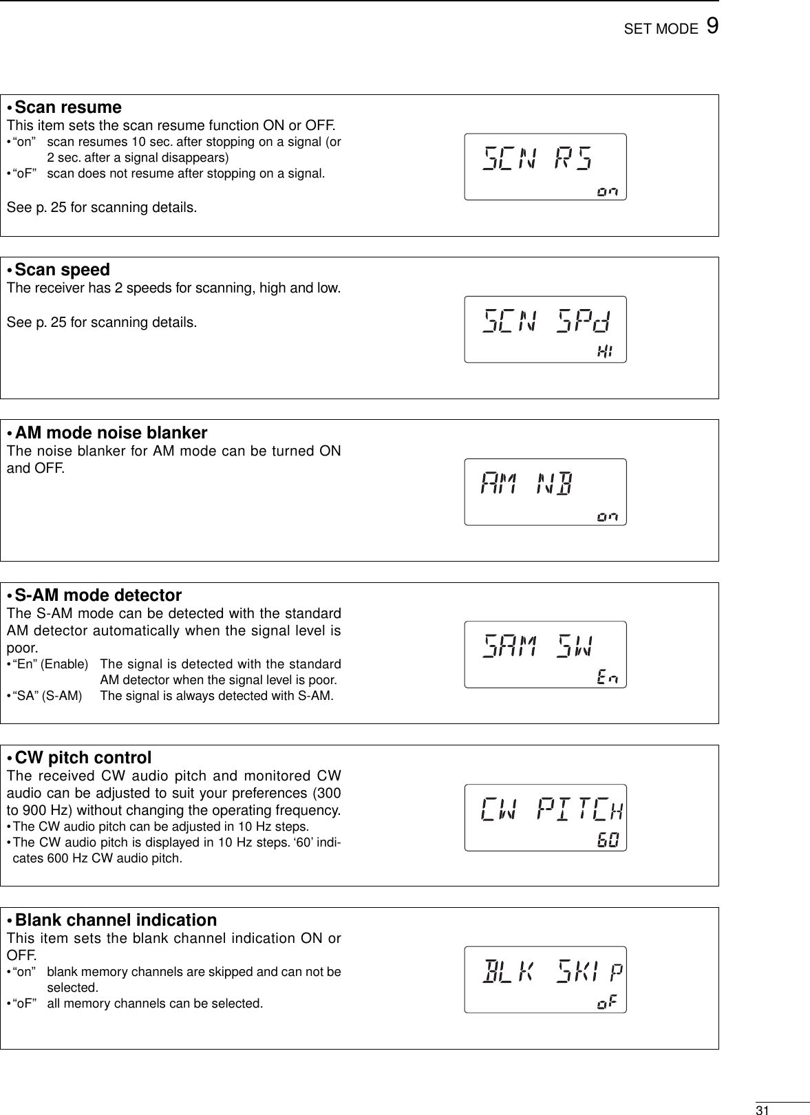
![930SET MODE■Set mode descriptionSet mode is used for programming infrequentlychanged values or conditions of functions.DSet mode operationqPush [(ANT)SET] to enter the set mode.wPush [UPY] or [ZDN] to select the desired item.eSet the desired condition using the tuning dial.rPush [(ANT)SET] to exit the set mode.•RF/squelch controlThe [RF/SQL] control can be set as the squelch con-trol (default; RF gain is fixed at maximum), the RFgain control only (squelch is fixed as open) orRF/squelch control.See p. 14 for details.•Confirmation beepA beep sounds each time a switch is pushed to con-firm it. This function can be turned OFF for silent op-eration.The volume level can be set in the next item.•Beep levelThis item adjusts the volume level for confirmationbeep tones from 0% to 100% in 1% steps.•The volume level is displayed in 10% steps. ‘5’ indicates50% volume level.•S-meter peak holdThe peak level of the S-meter can be displayed for 0.5sec. to confirm it easily.•Beep level limitThis item limits the maximum volume level for confir-mation beep tones.](https://usermanual.wiki/ICOM-orporated/IC-R75.manual/User-Guide-30547-Page-32.png)
![329SET MODE•Recorder remoteThis item sets the [REC REMOTE] jack function ONor OFF.•CI-V addressTo distinguish equipment, each CI-V transceiver or re-ceiver has its own Icom standard address in hexa-decimal code.The IC-R75’s address is 5Ah.When 2 or more IC-R75’s are connected to an op-tional CT-17 CI-V LEVEL CONVERTER, rotate the tuningdial to select a different address for each IC-R75 inthe range 01h to 7Fh.•CI-V baud rateThis item sets the data transfer rate. “3” (300 bps),“12” (1200 bps), “48” (4800 bps), “96” (9600 bps), “HI”(19200 bps) and “At” (automatic) are available.When “At” is selected, the baud rate is automaticallyset according to the connected controller or remotecontroller.•CI-V with IC-735When connecting the IC-R75 to the IC-735 for trans-ceive operation, you must change the operating fre-quency data length to 4 bytes.•This item must be set to “ON” only when operating receiverwith the IC-735.•Speech languageWhen the optional UT-102 VOICE SYNTHESIZER UNIT isinstalled, you can select between English and Japan-ese as the language.•“En” English announcement•“JP” Japanese announcementSee p. 34 for unit installation.•CI-V transceiveTransceive operation is possible with the IC-R75 con-nected to other Icom HF transceivers or receivers.When “on” is selected, changing the frequency, oper-ating mode, etc. on the IC-R75 automatically changesthose of connected transceivers (or receivers) andvice versa.](https://usermanual.wiki/ICOM-orporated/IC-R75.manual/User-Guide-30547-Page-34.png)
![1034OPTION INSTALLATIONS■Opening the receiver’s caseFollow the case and cover opening procedures shownhere when you want to install an optional unit or adjustan internal unit, etc.CAUTION: DISCONNECT the DC power cablefrom the receiver before performing any work on thereceiver. Otherwise, there is danger of electric shockand/or equipment damage.qRemove the 2 screws from the left side of the re-ceiver to remove an optional carrying handle, if nec-essary.wRemove the 4 screws from the top of the receiverand 4 screws from the sides, then lift up the topcover.eRemove the 2 screws from the bottom of the re-ceiver, slide the cover backward, then remove thebottom cover.The UT-102 announces the received frequency,mode, S-meter level and current time in a clear, elec-tronically-generated voice, in English (or Japanese).➥Push [LOCK] for 2 sec. to announce the frequency,etc.qRemove the top cover as shown above.wRemove the protective paper attached to the bot-tom of the UT-102 to expose the adhesive strip.ePlug UT-102 into J1271 on the MAIN unit asshown at right.rReturn the top cover to its original position.■CR-282 HIGH STABILITY CRYSTAL UNITBy installing the CR-282, the total frequency stabilityof the receiver will be improved.qRemove the top cover as shown in the diagramabove.wRemove 5 screws from the PLL unit, disconnectP1 from J491 (MAIN unit), then remove the PLLunit.eRemove the supplied internal crystal and replacewith the CR-282.rAdjust the reference frequency at L2 using a fre-quency counter.tReturn the PLL unit and top cover to their originalpositions.PLL unitMAIN unitCR-282InternalcrystalConnect a frequency counter here and adjust the frequency to 60.00000 MHz.L2PLL unit■UT-102 VOICE SYNTHESIZER UNIT](https://usermanual.wiki/ICOM-orporated/IC-R75.manual/User-Guide-30547-Page-36.png)
![■Resetting the CPU Resetting CLEARS all programmed contents inmemory channels and returns programmed valuesin set mode to their defaults.When first applying power or when the function seemsto be displaying erroneous information, reset the CPUas follows:qMake sure receiver power is OFF.wWhile pushing [UPY] and [ZDN], push [POWER]to turn power ON.•The internal CPU is reset.•The receiver displays its initial VFO frequencies when re-setting is complete.1136MAINTENANCE■TroubleshootingThe following chart is designed to help you correctproblems which are equipment malfunctions. If you are not able to locate the cause of a problem orsolve it through the use of this chart, contact your near-est Icom Dealer or Service Center.[POWER] [ZDN] [UPY]PROBLEM POSSIBLE CAUSE SOLUTION REF.POWERPower does not come onwhen the [POWER] switchis pushed.•DC power cable is improperly connected.•Fuse is blown.•Reconnect the DC power cable correctly.•Check for the cause, then replace the fuse witha spare one.(Fuses are installed in the DC power cableand the internal MAIN unit.)—p. 37RECEIVENo sound comes from thespeaker.•Volume level is too low.•The squelch is closed.•Rotate [AF] clockwise to obtain a suitablelistening level.•Rotate [RF/SQL] to 12 o’clock position to openthe squelch.p. 2p. 14Sensitivity is low. •The antenna is not connected properly.•The antenna for another band is selected.•The attenuator is activated.•Reconnect to the antenna connector.•Select an antenna suitable for the operatingfrequency.•Push [ATT] to turn the function OFF.—p. 16p. 16Receive audio is distorted. •The operating mode is not selected correctly.•PBT function is activated.•Noise blanker function is activated.•Preamp is activated.•The optional noise reduction is activated andthe [NR] level is set too high.•Select a suitable operating mode.•Set [TWIN PBT] to the center position.•Push [NB] to turn the function OFF.•Push [P.AMP] once or twice to turn the functionOFF.•Push [NR] to turn the function OFF.p. 14p. 15p. 15p. 16p. 20SCANProgrammed scan doesnot stop.•Squelch is open.•[RF/SQL] is assigned to RF gain control andsquelch is open.•Set [RF/SQL] to the threshold point.•Reset [RF/SQL] control assignment and set it tothe threshold point.p. 14pgs. 14, 30Programmed scan doesnot start.•The same frequencies have been programmedin scan edge memory channels P1 and P2.•Program different frequencies in scan edgememory channels P1 and P2. p. 22Memory scan does notstart.•2 or more memory channels have not beenprogrammed.•Program 2 or more memory channels. p. 22Select memory scan doesnot start.•2 or more memory channels have not beendesignated as select channels.•Designate 2 or more memory channels as selectchannels for the scan.p. 26DISPLAY“F.AGC” flashes in thefunction display.•A scan or band scope function is activated viaan optional RS-R75 remote control software.•If these functions are not in use, push [AGC] todeactivate the function.—The displayed frequencydoes not change properly.•The dial lock function is activated.•The internal CPU has malfunctioned.•Push [LOCK] to deactivate the function.•Reset the CPU.p. 13Seebelow.](https://usermanual.wiki/ICOM-orporated/IC-R75.manual/User-Guide-30547-Page-38.png)
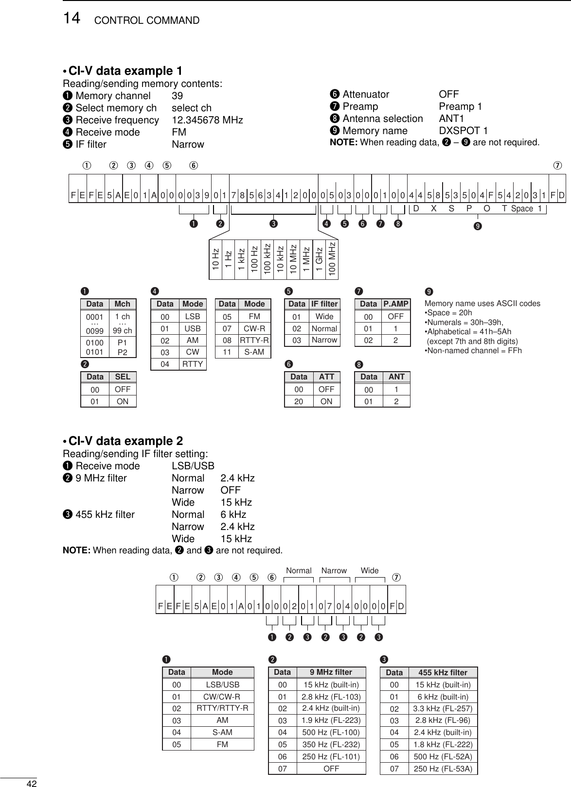
![4114CONTROL COMMAND•Command tableSub commandCommand Description—00 Send frequency dataSame as command 06Same as command 0601 Send mode data—02 Read band edge frequencies—03 Read operating frequency04 Read operating mode—05 Set frequency data00*101*102*103*104*105*107*108*111*1Set LSBSet USBSet AMSet CWSet RTTYSet FMSet CW-RSet RTTY-RSet S-AM06*1Add 00, 01 or 02 for selecting wide, normal or narrow filter, respectively. ——07 Select VFO mode0001 – 0101*2Select memory modeSelect memory channel*2P1=0100, P2=010108—09 Memory write—0A Memory to VFO—0B Memory clear000102042223B0B1D0D30EScan stopProgrammed/memory scan startProgrammed scan startAuto memory write scan startMemory scan startSelect memory scan startSet as non-select channelSet as select channelSet scan resume OFFSet scan resume ON0001020304050607080910111010 Hz (1 Hz) tuning step100 Hz tuning step1 kHz tuning step5 kHz tuning step6.25 kHz tuning step9 kHz tuning step10 kHz tuning step12.5 kHz tuning step20 kHz tuning step25 kHz tuning step100 kHz tuning step1 MHz tuning stepSub commandCommand Description002011 Attenuator OFFAttenuator ONSelect [ANT1]Select [ANT2]000112Announce with voice synthesizer(00=all data; 01=frequency and S-meter level; 02=receive mode)00010201 + level data13[CW PITCH] setting (0000=low pitch to 0255=high pitch)1415161819Read squelch conditionRead S-meter level01020212224041Set preamp (00=OFF; 01=preamp 1; 02=preamp 2)Set AGC time constant (00=OFF; 01=S-fast; 02=fast; 03=slow)Set noise blanker (00=OFF; 01=ON)Set optional noise reduction (00=OFF; 01=ON)Set optional auto notch (00=OFF; 01=ON)Turn the receiver power ONTurn the receiver power OFFRead the receiver IDSend/read memory contents(See example 1 on p. 42)Send/read IF filter setting(See example 2 on p. 42)Send/read set mode contents(See example 3 on p. 43)0001001A 00 + data01 + data02 + data[AF] level setting (0000=max. CCW to 0255=max. CW)[RF] level setting (0000=max. CCW to 0255=11 o’clock)[SQL] level setting (0000=11 o’clock to 0255=max. CW)[NR] level setting (0000=min. to 0255=max.)Inside [TWIN PBT] setting (0000=max. CCW, 0128=center, 0255=max. CW)Outside [TWIN PBT] setting (0000=max. CCW, 0128=center, 0255=max. CW)09 + level data08 + level data07 + level data06 + level data03 + level data02 + level data](https://usermanual.wiki/ICOM-orporated/IC-R75.manual/User-Guide-30547-Page-43.png)