ICOM orporated IC-R75 Scanning Receiver User Manual
ICOM Incorporated Scanning Receiver
UserManual.wiki
>
ICOM orporated
>
IC-R75 User Manual
>
User Manual
Contents
1.
manual
2.
User Manual
User Manual
Navigation menu
Upload a User Manual
Namespaces
Wiki Guide
HTML
PDF
Info
Views
User Manual
Discussion / Help
Navigation
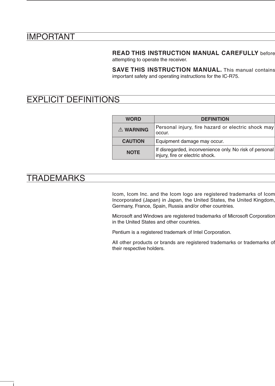
![RWARNING NEVER apply AC to the [DC13.8V] jack on the receiver rear panel. This could cause a fire or ruin the receiver.RWARNING NEVER apply more than 16 V DC, such as a 24 V battery, to the [DC13.8V] jack on the receiver rear panel. This could cause a fire or ruin the receiver.RWARNING NEVER let metal, wire or other objects touch any internal part or connectors on the rear panel of the receiver. This may result in an electric shock.NEVER expose the receiver to rain, snow or any liquids.DO NOT use or place the receiver in areas with temperatures below –10°C (+14°F) or above +60°C (+140°F). Be aware that temperatures on a vehicle’s dashboard can exceed 80°C (+176°F), resulting in permanent damage to the receiver if left there for extended periods.DO NOT place the receiver in excessively dusty environments or in direct sunlight.DO NOT place the receiver against walls or putting anything on top of the receiver. This will obstruct heat dissipation.Place unit in a secure place to avoid inadvertent use by children.During mobile operation, DO NOT operate the receiver without running the vehicle’s engine. When receiver power is ON and your vehicle’s engine is OFF, the vehicle’s battery will soon become exhausted.Make sure the receiver power is OFF before starting the vehicle. This will avoid possible damage to the receiver by ignition voltage spikes.For U.S.A onlyCAUTION: Changes or modifications not expressly approved by the party responsible for compliance could void the user's authority to operate the equipment.PRECAUTIONSiiFOR CLASS B UNINTENTIONAL RADIATORSThis equipment has been tested and found to comply with the limits for a Class B digital device, pursuant to part 15 of the FCC Rules. These limits are designed to provide reasonable protection against harmful interference in a residential installation. This equipment generates, uses and can radiate radio frequency energy and, if not installed and used in accordance with the instructions, may cause harmful interference to radio communications. However, there is no guarantee that interference will not occur in a particular installation. If this equipment does cause harmful interference to radio or television reception, which can be determined by turning the equipment off and on, the user is encouraged to try to correct the interference by one or more of the following measures: • Reorient or relocate the receiving antenna. • Increase the separation between the equipment and receiver. • Connect the equipment into an outlet on a circuit different from that to which the receiver is connected. • Consult the dealer or an experienced radio/TV technician for help.Versions of the IC-R75 which display the “CE” symbol on the serial number label comply with the European harmonised standard ETS300 684 (EMC product standard for Commercially Available Amateur Radio Equipment).](https://usermanual.wiki/ICOM-orporated/IC-R75.User-Manual/User-Guide-1145975-Page-3.png)
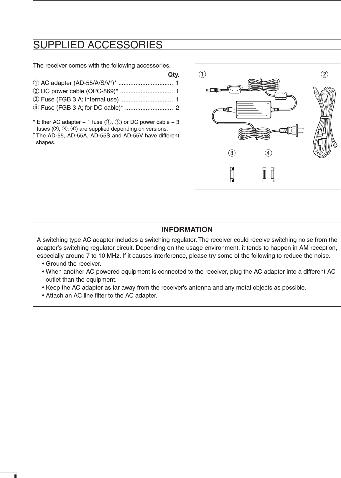
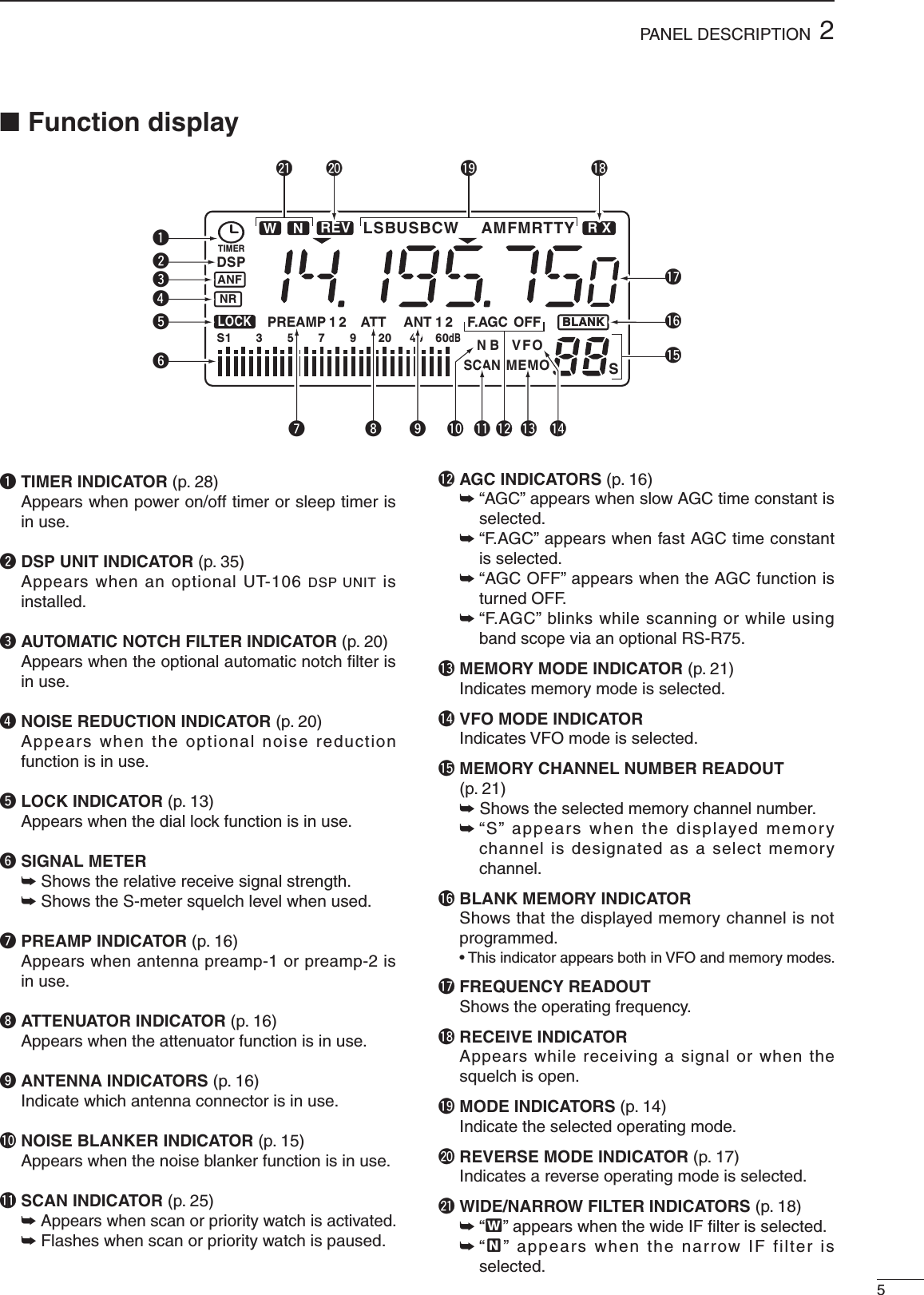
![■ Front panelq POWER SWITCH [POWER] ➥ Push momentarily to turn power ON. • Turn the optional DC power supply ON in advance. ➥ Push for 2 sec. to turn power OFF.w HEADPHONE JACK [PHONES] (p. 8) Accepts headphones. • When headphones are connected, the internal speaker or connected external speaker does not function.e AF CONTROL [AF] (inner control) Varies the audio output level from the speaker.r RF GAIN/SQUELCH CONTROL [RF/SQL] (outer control; pgs. 14, 30) Adjusts the squelch threshold level. The squelch removes noise output from the speaker (closed condition) when no signal is received. • The squelch is particularly effective for FM. It is also available for other modes. • The control can be set as the squelch plus RF gain controls or squelch control only (RF gain is fixed at maximum) in set mode.t PASSBAND TUNING CONTROLS [TWIN PBT] (p. 15) Adjust the receiver’s “passband width” of the 455 kHz and 9 kHz IF filters for the inner and outer controls, respectively. • Set to the center positions when not in use.y CLOCK MODE SWITCH [CLOCK] (p. 28) Toggles between frequency indication and clock indication when pushed.u ANTENNA SELECTOR/SET MODE SWITCH [ANT/SET] (pgs. 16, 30) ➥ While in a frequency indication, enters set mode when pushed. ➥ While in a frequency indication, toggles between the antenna 1 and 2 connectors when pushed for 2 sec. ➥ While in the clock indication, enters time setting condition when pushed for 2 sec. ➥ While in a timer indication, toggles the timer ON or OFF when pushed.i TUNING DIAL Changes the displayed frequency, selects set mode items, etc.o TUNING DIAL TENSION LATCH Adjusts the tension of the tuning dial.!0 LOCK/SPEECH SWITCH [LOCK] (pgs. 13, 34) ➥ Toggles the frequency lock function ON and OFF. ➥ Announces the selected readout frequency when an optional UT-102 is installed and when pushed for 2 sec.22PANEL DESCRIPTIONFILTSCW/RTTYFMSSBAMPHONES POWERRF/ SQL TWIN PBTAFCOMMUNICATIONS RECEIVERDN UP1 2ABC3DEF4GHI5JKL6MNO7PRS8TUV9WXY.0QZENTV/M MWSEL SCANCLRLOCKAGCNBANFNRATTP.AMPSETCLOCKANTFunction display (p. 5)Speakerqwe r t y i o !0!1!3!4!5!6!7!8!2u](https://usermanual.wiki/ICOM-orporated/IC-R75.User-Manual/User-Guide-1145975-Page-6.png)
![32PANEL DESCRIPTION!1 MEMORY CHANNEL UP/DOWN SWITCHES [√ DN]/[UP ∫] (p. 21) ➥ Select a memory channel. ➥ Select a set mode contents while in set mode. ➥ Select a timer or time indication while in clock indication. ➥ Select a filter set mode contents while in filter set mode.!2 MEMORY WRITE SWITCH [MW] (pgs. 22, 27) ➥ Stores the displayed frequency and operating mode into the selected memory channel when pushed for 2 sec. ➥ Toggles the programmed scan and auto memory write scan when pushed.!3 CLEAR SWITCH [CLR] (p. 24) ➥ Clears the input digits while inputting a frequency or memory channel number. ➥ Clears the selected memory channel contents when pushed for 2 sec. in memory mode. • This switch does not function in VFO mode.!4 VFO/MEMORY SWITCH [V/M] (pgs. 21, 23) ➥ Toggles the operating mode between VFO mode and memory mode when pushed. ➥ Selects a memory channel for inputting a memory channel number when pushed. ➥ Transfers the memory contents to VFO when pushed for 2 sec.!5 KEYPAD (pgs. 11, 21) The keypad can be used for several functions as below: • Keypad then [ENT] — Direct frequency input. • Keypad then [V/M] — Memory channel selection. • [ENT] then keypad in memory name indication mode — Alphanumeric input for memory name, etc.!6 QUICK TUNING STEP SWITCH [TS] (pgs. 12, 13) ➥ Selects a quick tuning step or turns the quick tuning step OFF. • While the quick tuning indicator (√) is displayed, the frequency can be changed in kHz or MHz steps. ➥ While the quick tuning step is OFF, turns the 1 Hz step ON and OFF when pushed for 2 sec. • 1 Hz indication appears and the frequency can be changed in 1 Hz steps. ➥ While the kHz quick tuning step is selected, enters tuning step set mode when pushed for 2 sec. ➥ While the memory name indication is selected in memory mode, pushing this switch shows the operating frequency; and rotating the tuning dial while pushing this switch changes the frequency temporally.!7 FILTER SWITCH [FIL] (pgs. 18, 19) ➥ Push momentarily to toggle between the pre-programmed normal, wide and narrow IF filters for the selected operating mode. ➥ Push for 2 sec. to enter filter set mode.!8 MODE SWITCHES [SSB]/[CW/RTTY]/[AM]/[FM] (p. 14) Select an operating mode. • Push [SSB] to toggle between LSB and USB. • Push [CW/RTTY] to toggle between CW and RTTY. • Push [CW/RTTY] for 2 sec. to toggle between CW and CW reverse or RTTY and RTTY reverse. • Push [AM] to select AM. • Push [FM] to select FM.](https://usermanual.wiki/ICOM-orporated/IC-R75.User-Manual/User-Guide-1145975-Page-7.png)
![42PANEL DESCRIPTION■ Front panel (continued)!9 PREAMP SWITCH [P.AMP] (p. 16) Push to toggle between preamp-1 and preamp-2 or turn the preamp OFF.@0 ATTENUATOR SWITCH [ATT] (p. 16) Push to toggle the 20 dB attenuator function ON and OFF.@1 NOISE REDUCTION SWITCH [NR] (p. 20) ➥ Toggles the optional noise reduction function ON and OFF when pushed. Functions in SSB, CW and RTTY modes. An optional UT-106 DSP UNIT is required. ➥ Enters noise reduction level set mode when pushed for 2 sec. An optional UT-106 DSP UNIT is required.@2 AUTOMATIC NOTCH FILTER SWITCH [ANF] (p. 20) Push to turn the optional automatic notch filter for receiving AM signals ON and OFF. An optional UT-106 DSP UNIT is required.@3 NOISE BLANKER SWITCH [NB] (p. 15) Toggles the noise blanker ON and OFF. The noise blanker reduces pulse-type noise such as that generated by automobile ignition systems. This function is not effective for FM, or non pulse-type noise.@4 AGC SWITCH [AGC] (p. 16) ➥ Toggles the AGC (Automatic Gain Control) time constant fast and slow when pushed. ➥ Toggles the AGC function ON and OFF when pushed for 2 sec.@5 SELECT SWITCH [SEL] (pgs. 24, 26) ➥ Toggles the select memory setting ON and OFF when pushed in memory mode. ➥ Toggles the memory name indication ON and OFF when pushed for 2 sec. in memory mode.@6 SCAN SWITCH [SCAN] (p. 25) ➥ Push momentarily to start/stop the programmed scan in VFO mode. ➥ Push momentarily to start/stop the memory scan in memory mode. ➥ Push for 2 sec. to start the priority watch in VFO mode. • Push [SCAN] again to cancel the priority watch.FILTSCW/RTTYFMSSBAMPHONES POWERRF/ SQL TWIN PBTAFCOMMUNICATIONS RECEIVERDN UP1 2ABC3DEF4GHI5JKL6MNO7PRS8TUV9WXY.0QZENTV/M MWSEL SCANCLRLOCKAGCNBANFNRATTP.AMPSETCLOCKANTFunction display (p. 5)!9@0@1@2@3@4@6@5](https://usermanual.wiki/ICOM-orporated/IC-R75.User-Manual/User-Guide-1145975-Page-8.png)
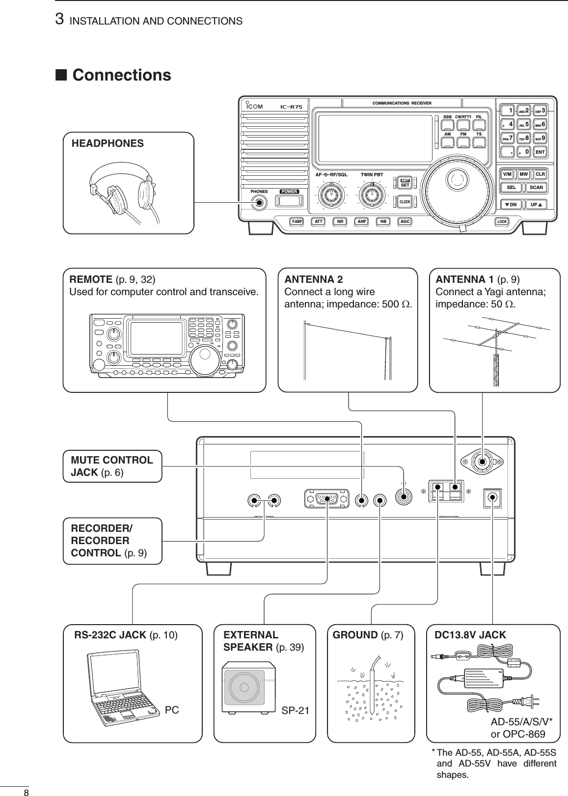
![62PANEL DESCRIPTION■ Rear panelq RECORDER REMOTE JACK [REC REMOTE] Controls the running of a tape recorder for recording. Connects to the REMOTE jack on a tape recorder. • This function can be turned OFF in set mode. (p. 32)w RECORDER JACK [REC] Outputs receive audio signals. Connects to the AUX or LINE IN jack on a tape recorder.e RS-232C CONNECTOR [RS-232C] Connects an RS-232C cable. An RS-232C cable can be used to connect the receiver to a PC. In this way commands can be sent to the receiver via the PC.r CI-V REMOTE CONTROL JACK [REMOTE] Allows connection to an Icom CI-V system transceiver or another receiver for the transceive function. Also connects to a PC with several receivers for command control via an optional CT-17 CI-V LEVEL CONVERTER.t EXTERNAL SPEAKER JACK [EXT SP] Connects an 8 Ω external speaker, if desired. • When an external speaker is connected, the internal speaker does not function.y MUTE CONTROL JACK [MUTE] Mutes audio outputs and attenuates the receive signal input when grounded. Used for CI-V transceive operation with a transceiver.u GROUND TERMINAL [GND] (p. 7) Connects the black terminal to ground.i ANTENNA 2 TERMINAL [ANT 2] (p. 9) Connects the red terminal to a 500 Ω long wire antenna.o ANTENNA 1 CONNECTOR [ANT 1] (p. 9) Connects a 50 Ω antenna with a PL-259 connector and a 50 Ω coaxial cable.!0 DC POWER JACK [DC 13.8V] (p. 8) ➥ Connects the supplied AC adapter for versions with an AC adapter. ➥ Connects to a 13.8 V DC power source using the supplied DC cable for versions without an AC adapter. • Current of 1.5 A or greater is required. DO NOT use a cigarette lighter socket as a power source when operating in a vehicle. The plug may cause voltage drops and ignition noise may be superimposed onto received audio.q w r t y u ie o !0](https://usermanual.wiki/ICOM-orporated/IC-R75.User-Manual/User-Guide-1145975-Page-10.png)
![■ GroundingTo prevent accidents involving electricity and interference from transceivers, ground the receiver through the [GND] terminal on the rear panel.For best results, connect a heavy gauge wire or strap to a long earth-sunk copper rod. Make the distance between the [GND] terminal and ground as short as possible. R WARNING: NEVER connect the [GND] terminal to a gas or electric pipe, since the connec-tion could cause an explosion or electric shock.■ Receiver standThe base of the receiver has an adjustable stand for desktop use. Set the stand to one of two angles depending on your operating conditions.■ Optional bracket and carrying handleD Mounting bracketAn optional IC-MB5 MOBILE MOUNTING BRACKET is available to install the radio under a table, on a wall, in a vehicle, etc.Select an area to mount the receiver keeping in mind that the weight of the receiver is approx. 3 kg.D Carrying handleAn optional handle allows you to easily carry and transport the receiver.Attach the MB-23 CARRYING HANDLE with the supplied rubber feet as shown.37INSTALLATION AND CONNECTIONSFlat washer](https://usermanual.wiki/ICOM-orporated/IC-R75.User-Manual/User-Guide-1145975-Page-11.png)
![■ Tape recorder connections■ Transceive function93INSTALLATION AND CONNECTIONSPL-259 CONNECTOR INSTALLATION EXAMPLE30 mm10 mm (soft solder)10 mm1–2 mmsolder solderSoftsolderCoupling ringSlide the coupling ring down. Strip the cable jacket and soft solder.Slide the connector body on and solder it.Screw the coupling ring onto the connector body.Strip the cable as shown at left. Soft solder the center con-ductor.(10 mm ≈ 3⁄8 in)qwer■ Antenna connectionAntennas play a very important role in receiver operation. Connecting a poor quality antenna to the receiver will result in less than optimum performance.When using a 50 Ω antenna, use [ANT 1] connector for connection. When using a 500 Ω long wire antenna, use [ANT 2] terminal for connection.The [REC OUT] jack has 350 mV rms/4.7 kΩ output for connection to other audio equipment.[REC REMOTE] jack: Grounds when a signal is received and squelch opens. If a tape recorder has a control terminal, this jack can be used for recording control. (1 A/DC max.)[RECREMOTE][REC OUT]350 mVrms4.7 kΩ[AUX IN] or[LINE IN] jackIC-R75Icom CI-V transceivers or receivers can be connected via the [REMOTE] jack. The frequency and mode become the same* when either radio is changed.* When a set frequency is out-of-range for one of the connected transceivers or receivers, the connected radio’s frequency/mode does not change.[REMOTE]IC-R75Icom CI-V transceiver/receiverConnect to [REMOTE] jack Be sure the “CIV TRn” item is turned ON in set mode (p. 32).](https://usermanual.wiki/ICOM-orporated/IC-R75.User-Manual/User-Guide-1145975-Page-13.png)
![103INSTALLATION AND CONNECTIONS■ Connecting to a PCTo connect a terminal unit, TNC or scan converter, refer to the diagram below.q Connect a terminal unit as below.w Select RTTY mode (or USB, CW modes for HF band data communications).e Set the receiver to the desired frequency as at right.r Set the connected terminal unit to the appropriate settings. • Refer to the terminal unit’s instructions. The optional 250 Hz CW narrow filters may not pass RTTY signals. Be sure to select the appropriate IF filters corresponding to the signal width. (pgs. 18, 19)Frequency settings depend on the mode used. FM mode: [Setting frequency (displayed freq.)] = [Desired freq.] USB mode: [Setting frequency (displayed freq.)] = [Desired freq.] – [Center of Mark and Space freq.] CW narrow mode: [Setting frequency (displayed freq.)] = [Desired freq.] – [Center of Mark and Space freq.] + [600 Hz] LSB mode (for amateur RTTY): [Setting frequency (displayed freq.)] = [Desired freq.] + [Mark freq.]The RS-R75 remote control software is available to perform data setting and remote control of the receiver.Refer to the diagram below for connection.D System requirementsTo use this program, the following hardware and software are required:• IBM PC compatible computer• An RS-232C serial port• Microsoft® Windows® 95 or Microsoft® Windows® 98• Intel i486DX4 processor or faster (Pentium® 100 MHz or faster recommended)• At least 16 MB RAM• At least 10 MB of hard disk space• At least 640 × 480 pixel, high color (16 bit) display■ FSK and AFSK (SSTV) connectionsTU or TNCAF INSQUELCH INto [REC]to [REC REMOTE]2-conductor 3.5(d) plugsPCPC IC-R75Supplied RS-232C cable (OPC-743)](https://usermanual.wiki/ICOM-orporated/IC-R75.User-Manual/User-Guide-1145975-Page-14.png)
![411FREQUENCY SETTING■ Read me firstThe receiver uses memory channels for storage of frequencies (as well as mode, tuning steps, etc.). When turning power OFF or changing memory channels, the previously displayed frequency cannot be recalled unless it has been stored into a memory channel. Therefore, when you want to keep a displayed frequency for later recall, you must program it into a memory channel by pushing [MW] for 2 sec.See p. 22 for details.■ Using the keypadq Push the numeral keys on the keypad to enter the MHz digits for the desired frequency. • If a key is mistakenly pushed, push [CLR] and start again from the beginning. • When entering the same MHz digits as the displayed frequency, this step can be skipped.w Push [•] on the keypad.e Push the numeral keys to enter the frequency digits below 1 MHz. • If a key is mistakenly pushed, push [CLR] and start again from the beginning.r Push [ENT] to set the input frequency. • When pushing [ENT] after entering the MHz digits, zeros are automatically entered for the kHz digits.BLANKBLANKS1 3 57920 40 60dBAGCANTUSB R XVFO1“BLANK” appears above the memory channel readout until [MW] is pushed for 2 sec.Push [MW] for 2 sec. after tuning.[EXAMPLE]: Setting the frequency using the keypad.USBR XUSBUSBR XUSBR XUSBR XUSBR XUSBR X R XUSBR XUSBR XUSBR XUSBR XUSBR XUSBR XUSBR XUSBR X15JKL8TUV...0QZ5JKL8TUVUSBR X0QZ•To set to 28.00 MHz2ABC8TUVENT5JKLENT•To set to 21.050 MHz2ABC•To set to 850 kHz (0.850 MHz)ENTENT•To change 14.19075 to 14.850 MHz](https://usermanual.wiki/ICOM-orporated/IC-R75.User-Manual/User-Guide-1145975-Page-15.png)
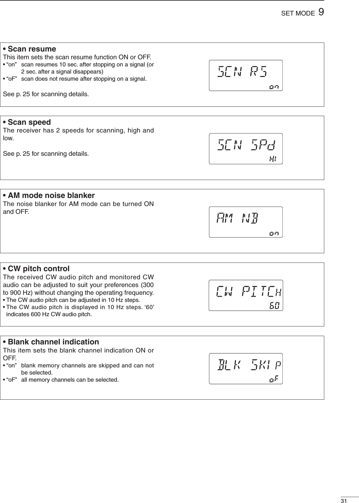
![124FREQUENCY SETTING■ Frequency settingRotate the tuning dial to change the frequency.• The frequency changes in increments determined by the selected tuning step (see below).• When the lock function is activated (“LOCK” appears), the frequency cannot be changed via tuning dial.Push [TS] one or more times to select a quick tuning step.D Programmable tuning stepsProgrammable tuning steps are available to suit your operating requirements.These tuning steps are:• Independently selectable for each mode• Selectable from 0.1, 1, 5, 6.25, 9, 10, 12.5, 20, 25, 100 kHzq Select the desired operating mode with [SSB], [CW/RTTY], [AM] or [FM]. (p. 14)w Push [TS] one or more times until the programmable tuning step indicator, “√,” appears above the 1 kHz. • Rotating the tuning dial changes the frequency according to the set tuning step.e Push [TS] for 2 sec. while the programmable tuning step indicator appears to enter the tuning step set mode.r Rotate the tuning dial to set the desired tuning step for the selected mode.t Push [TS] to exit the tuning step set mode.y Rotate the tuning dial to change the frequency according to the set tuning step.D 1 Hz and 10 Hz tuning stepsWhen both the 1 MHz tuning step and programmable tuning step, “√,” disappear, rotating the tuning dial changes the frequency in increments of 1 or 10 Hz.q Push [TS] one or more times until the programmable tuning step indicator or 1 MHz tuning step indicator, “√,” disappears.w Push [TS] for 2 sec. to toggle between the 1 and 10 Hz step settings. • When the 1 Hz step is selected, the 1 Hz digit appears in the frequency indication; when the 10 Hz step is selected, the 1 Hz digit disappears from the frequency indication.USB R XBLANKBLANKS1 3 57920 40 60dBAGCANTVFO1Programmable tuningstep indicator10 kHz tuning step isselected.[TS]USBR XBLANKBLANKS1 3 57920 40 60dBAGCANTVFO1USBR XBLANKBLANKS1 3 57920 40 60dBAGCANTVFO1Rotating the tuning dialchanges the frequencyin 10 Hz steps.Rotating the tuning dialchanges the frequencyin 1 Hz steps.TSPush for 2 sec.](https://usermanual.wiki/ICOM-orporated/IC-R75.User-Manual/User-Guide-1145975-Page-16.png)
![134FREQUENCY SETTINGD 1 MHz quick tuning stepThe quick tuning step function allows you to change the frequency in 1 MHz steps when rotating the tuning dial.Push [TS] one or more times until the 1 MHz tuning step indicator, “√,” appears above the 1 MHz indicator.USBR XBLANKBLANKS1 3 57920 40 60dBAGCANTVFO1Quick tuning step indicator10 Hz tuning1 Hz tuningmomentarily2 sec.2 sec.2 sec.1 MHz tuningProgrammable step tuning(100 Hz –100 kHz)Selectable for each mode.momentarilymomentarilyUSBR XUSBR XUSBR XUSBR X[TS] SWITCH FLOW CHART■ Dial lock functionThe dial lock function prevents accidental changes caused by the tuning dial. The lock function electronically locks the dial.Push [LOCK] momentarily to toggle the lock function ON and OFF.• “LOCK” appears in the function display while the lock function is activated.USBR XBLANKBLANKS1 3 57920 40 60dBAGCANTVFO1LOCK“LOCK” appears while the lock function is activated.[LOCK]](https://usermanual.wiki/ICOM-orporated/IC-R75.User-Manual/User-Guide-1145975-Page-17.png)
![514RECEIVE FUNCTIONS■ Mode selectionThe following modes are available in the IC-R75:SSB (LSB/USB), CW, CW REV (CW reverse), FM, AM, RTTY and RTTY REV (RTTY reverse).➥ Push [SSB] to toggle between LSB and USB.➥ Push [CW/RTTY] momentarily to toggle between CW and RTTY.➥ Push [CW/RTTY] for 2 sec. to toggle between CW and CW reverse or RTTY and RTTY reverse.➥ Push [AM] to select AM.➥ Push [FM] to select FM. The selected mode is indicated in the function display.OPERATING MODE SELECTIONSSBAMPush momentarilyFMPush momentarilyCW/RTTYCW CW REV RTTY RTTY REVPush mode switch for 2 sec.Push mode switchmomentarily.AMFMLSB USB■ Squelch and RF gainThe receiver uses the same control, [RF/SQL], to adjust one of either the RF gain or the squelch. [RF/SQL] adjusts either the RF gain or the squelch depending on the operating mode selected and the condition of the RF/SQL item in set mode (p. 30).• [RF/SQL] control priority * The RF gain is set to maximum level when the [RF/SQL] is set as [SQL] control.The RF (Radio Frequency) gain is used to adjust the receiver gain.• Shallow rotation moves the S-meter to the right indicating the signal strength which can be received. The recommended position for RF gain is the 12 o’clock position since this sets RF gain to the max.The SQUELCH removes noise output from the speaker (closed condition) when no signal is received. The squelch is particularly effective for FM. It is also available for the other modes.• When operating in FM, first rotate the control fully counterclockwise. Then, rotate the control clockwise to the point where the noise just disappears. This is the best position. The squelch does not open for weak signals when it is set too deep.• A segment appears in the S-meter to indicate the S-meter squelch level.• When set as the [RF/SQL] controlSet modesettingUSB, LSB,CW, RTTY AM, FMSq (SQL) SQL* SQL*At (AUTO) RF GAIN SQL*rS (RF/SQL) RF/SQL RF/SQLRecommended levelMinimum RF gainAdjustable rangeRF gain adjustablerangeMaximum RF gainMaximum RF gainSquelch is open. S-meter squelchS-meter squelchthresholdNoise squelch threshold (FM mode)Shallow DeepSquelch is open.S-meter squelchNoise squelch (FM mode)Noise squelch (FM mode)• When set as the [SQL] control• When set as the [RF] control](https://usermanual.wiki/ICOM-orporated/IC-R75.User-Manual/User-Guide-1145975-Page-18.png)
![155RECEIVE FUNCTIONS■ Twin PBT operationThe twin PBT (Passband Tuning) function electronically narrows the IF passband widths to reduce interference. Moving both [TWIN PBT] controls to the same position shifts the IF.Variable range depends on the filter selection. ±1.29 kHz in 15 Hz steps and ±258 kHz in 3 Hz steps are available.PBT OPERATION EXAMPLE • [TWIN PBT] should normally be set to the center positions when there is no interference. • When PBT is used, the audio tone may be changed. • PBT may not function with some IF filter combinations. • Not available for FM mode.TWIN PBT TWIN PBTTWIN PBTIF center frequency Interference Desired signalPassbandBoth controls at center positionCutting a lower passbandCutting both higher and lower passbandsInterference InterferenceDesired signalPassband■ Noise blankerThe noise blanker eliminates pulse-type noise such as from car ignitions. The noise blanker is not available for FM mode.➥ Push the [NB] switch to turn the noise blanker ON or OFF. • When using the noise blanker, received signals may be distorted if they are excessively strong. • The noise blanker function in AM mode can be deactivated depending on set mode setting. (p. 31)[NB]](https://usermanual.wiki/ICOM-orporated/IC-R75.User-Manual/User-Guide-1145975-Page-19.png)
![165RECEIVE FUNCTIONS■ Preamp The preamp amplifies received signals in the front end circuit to improve the S/N ratio and sensitivity. Turn this function ON when receiving weak signals.➥ Push [P.AMP] to toggle between preamp-1 and preamp-2 or turn the preamp OFF.■ AttenuatorThe attenuator prevents desired signals from distorting when very strong signals are near the desired frequency or when very strong electric fields, such as from broadcasting stations, are near your location.➥ Push [ATT] toggle the 20 dB attenuator function ON and OFF. • “ATT” appears when the attenuator is turned ON.■ AGC time constantThe AGC (Automatic Gain Control) controls receiver gain to produce a constant audio output level even when the received signal strength is varied by fading, etc. Use AGC slow for normal phone operation; AGC fast for receiving data and searching for signals.➥ Push [AGC] momentary to toggle the AGC time constant between fast and slow. • “F.AGC” appears when the fast time constant is selected. • “AGC” appears when the slow time constant is selected.➥ Push [AGC] for 2 sec. to turn the AGC circuit OFF. • “AGC OFF” appears when the AGC circuit is turned OFF. • Push [AGC] to turn the AGC circuit ON. • S-meter is deactivated when the AGC circuit is turned OFF.USB R XBLANKBLANKS1 3 57920 40 60dBAGCANTVFO1PREAMP 1“PREAMP” appears while the preamp is activated.■ Antenna selection2 types of antenna can be connected to this receiver. When 2 antennas are connected, select an antenna depending on the operating condition.➥ Push [ANT(SET)] for 2 sec. to toggle between the antenna 1 and 2 connectors. • If a blank memory channel has been selected, push [V/M] to select VFO mode in advance.USB R XBLANKBLANKS1 3 57920 40 60dBAGCANTVFO1“ANT1” appears when the [ANT1] connector is in use.USBR XBLANKBLANKS1 3 57920 40 60dBAGCANTVFO1ATT“ATT” appears while the attenuatoris activated.USBR XBLANKBLANKS1 3 57920 40 60dBAGCANTVFO1 F. AGC“F.AGC” appears when the fast time constant is selected.](https://usermanual.wiki/ICOM-orporated/IC-R75.User-Manual/User-Guide-1145975-Page-20.png)
![175RECEIVE FUNCTIONS■ CW reverse modeCW-R (CW Reverse) mode receives CW signals with a reverse side CW carrier point like that of LSB and USB modes.Use when interfering signals are near a desired signal and you want to change the interference tone.q Push [CW/RTTY] once or twice to select CW mode.w Push [CW/RTTY] for 2 sec. to toggle between CW and CW reverse (CW REV). • Check the interfering tone.• Receive audio tone response■ RTTY reverse modeReceived characters are occasionally garbled when the receive signal is reversed between MARK and SPACE. This reversal can be caused by incorrect TNC connections, settings, commands, etc.To receive a reversed RTTY signal correctly, select RTTY reverse mode.q Push [CW/RTTY] once or twice to select RTTY mode.w Push [CW/RTTY] for 2 sec. to toggle between RTTY and RTTY reverse (RTTY REV). • Check the receive signal.■ CW pitch controlThe received CW audio pitch and monitored CW audio can be adjusted to suit your preferences (300 to 900 Hz) without changing the operating frequency.The received CW audio pitch can be adjusted in 10 Hz steps.q Push [(ANT) SET] momentarily to enter set mode.w Push [UP Y] or [Z DN] to select the ‘CW PITCH’ item.e Rotate the tuning dial to set the desired CW audio pitch. • CW audio pitch is displayed in 10 Hz steps. ‘60’ indicates 600 Hz CW audio pitch.r Push [(ANT) SET] again to exit set mode.BFO1/3 octavePush for 2 sec.Desired signal(600 Hz)CW mode (USB side)Interference(800 Hz)BFO1/2 octaveDesired signal(600 Hz)CW REV mode (LSB side)Interference(400 Hz)CW/RTTYShows a 600 Hz CW audio pitch](https://usermanual.wiki/ICOM-orporated/IC-R75.User-Manual/User-Guide-1145975-Page-21.png)
![185RECEIVE FUNCTIONS■ Filter selectionThe filter selection switches the IF passband width as shown in the table at right.The filter selection is automatically memorized in each mode.q Select the desired mode with the mode switches.w Push [FIL] one or more times to select the desired filter combination. • ã or ç does not appear while in normal IF filter. • ç appears when wide IF filters are selected. • ã appears when narrow IF filters are selected. When an optional filter is installed, set the optional filter in filter set mode. Optional filters are not selected by default.• Filter constructionCFWS450E (15 kHz)CFWS450HT (6 kHz)FL-65 (2.4 kHz)FL-257 (3.3 kHz)FL-96 (2.8 kHz)FL-222 (1.8 kHz)FL-52A (500 Hz)FL-53A (250 Hz)optionalFL-23 (15 kHz)FL-272 (2.4 kHz)FL-103 (2.8 kHz)FL-223 (1.9 kHz)FL-100 (500 Hz)FL-232 (350 Hz)FL-101 (250 Hz)optionalMixer2nd IF signal 3rd IF signal9 MHz IF filter 455 kHz IF filterIF Filter PassbandwidthRecommendedselectivity9 MHzFL-100 500 Hz/–6 dB CW-N, RTTY-NFL-101 250 Hz/–6 dBFL-103 2.8 kHz/–6 dB SSB-WCW-NFL-223 1.9 kHz/–6 dB SSB-N455 kHzFL-52A 500 Hz/–6 dB CW-N, RTTY-NFL-53A 250 Hz/–6 dB CW-NFL-96 2.8 kHz/–6 dB SSB-WFL-232 350 Hz/–6 dB CW-N, RTTY-NFL-222 1.8 kHz/–6 dB SSB-NFL-257 3.3 kHz/–6 dB SSB-W](https://usermanual.wiki/ICOM-orporated/IC-R75.User-Manual/User-Guide-1145975-Page-22.png)
![195RECEIVE FUNCTIONS■ Filter set modeWhen an optional filter is installed, set the optional filters in filter set mode. Optional filters are not selected by default.D Optional filter settingq Push [FIL] for 2 sec. to enter filter set mode. • If a blank memory channel has been selected, push [V/M] to select VFO mode in advance.w Push [UP Y] or [Z DN] one or more times until “oP1” appears for 9 MHz IF filter setting or “oP2” appears for 455 kHz IF filter setting.e Rotate the tuning dial to select the installed filter. • “No,” “100,” “101,” “103,” “223” and “232” indicate no optional filter, FL-100, FL-101, FL-103, FL-223 and FL-232, respectively for 9 MHz IF filter selection. • “No,” “52A,” “53A,” “96,” “222” and “257” indicate no optional filter, FL-52A, FL-53A, FL-96, FL-222 and FL-257, respectively for 455 kHz IF filter selection.r Push [FIL] to exit filter set mode.D Wide/narrow filter settingq Push [FIL] for 2 sec. to enter filter set mode. • If a blank memory channel has been selected, push [V/M] to select VFO mode in advance.w Select the desired mode with the mode switches.e Push [UP Y] or [Z DN] one or more times to select the desired width 9 MHz or 455 kHz IF filter. • Wide or narrow mode can be deactivated when 9 MHz wide or narrow filter is set to ‘OFF.’ • 455 kHz wide or narrow filter selection does appear when 9 MHz wide or narrow filter is set to ‘OFF.’r Rotate the tuning dial to select a filter.t Repeat steps w and r to select IF filters for other modes, if desired. • The filter combinations are stored depending on operating modes.y Push [FIL] to exit filter set mode.D Expanded filter selection ON/OFFThe selectable filter combinations can be expanded by setting the expanded filter selection to ON.q Push [FIL] for 2 sec. to enter filter set mode. • If a blank memory channel has been selected, push [V/M] to select VFO mode in advance.w Push [UP Y] or [Z DN] one or more times until “EXP” appears.e Rotate the tuning dial to turn the expanded filter selection ON/OFF. • If ‘ON’ is selected, the expanded filter selection can be used.r Push [FIL] to exit filter set mode. * 455 kHz wide or narrow filter selection does appear when 9 MHz wide or narrow filter is set to ‘OFF.’USBWUSBWUSBNUSBUSBUSBNUSBUSBUSB•9 MHz normal filter selection•455 kHz normal filter selection•9 MHz narrow filter selection•455 kHz narrow filter selection*•9 MHz wide filter selection•455 kHz wide filter selection*•Expanded filter selection ON/OFF•9 MHz normal filter selection•455 kHz normal filter selection](https://usermanual.wiki/ICOM-orporated/IC-R75.User-Manual/User-Guide-1145975-Page-23.png)
![205RECEIVE FUNCTIONS■ Optional auto notch functionWhen an optional UT-106 is installed (DSP appears in the function display), an auto notch function can be used.The function automatically attenuates more than 3 beat tones, tuning signals, etc., even if they are moving. The auto notch functions in SSB mode only.q Select SSB mode.w Push [ANF] to turn the auto notch function ON. • [ANF] indicator appears.e Push [ANF] again to cancel the function. • [ANF] indicator disappears.Unwanted tone frequencyDesired signal (AF)Desired signal (AF)Particular frequencyis attenuatedAuto notch OFF Auto notch ONoptional UT-106■ Optional noise reduction functionWhen an optional UT-106 is installed (DSP appears in the function display), noise reduction function can be used.The noise reduction function reduces noise components and picks out desired signals which are buried in noise. The received AF signals are converted to digital signals and then the desired signals are separated from the noise.q Push [NR] to turn the noise reduction ON. • [NR] indicator appears.w Push [NR] for 2 sec. to enter the noise reduction level setting condition.e Rotate the tuning dial to adjust the noise reduction level.r Push [NR] to exit the setting condition.t Push [NR] again to turn the noise reduction OFF. • [NR] indicator disappears.• Noise reduction example Higher setting of the [NR] level results in audio signal masking or distortion. Set the [NR] level for maximum clarity. The noise reduction function is available in all modes, including AM and FM modes.Noise reduction OFF Noise reduction activatedDesired signal (CW)Noise componentsoptional UT-106](https://usermanual.wiki/ICOM-orporated/IC-R75.User-Manual/User-Guide-1145975-Page-24.png)
![■ Memory channelsThe receiver has 101 memory channels. The memory mode is very useful for quickly changing to often-used frequencies.All 101 memory channels are tuneable which means the programmed frequency can be tuned temporarily with the tuning dial, etc. in memory mode.■ Memory channel selection621MEMORY OPERATIONMEMORYCHANNELMEMORYCHANNELNUMBERCAPABILITY TRANSFERTO VFOOVER-WRITING CLEARRegular memorychannels 1–99 One frequency and one mode ineach memory channel. Yes Yes YesScan edgememorychannelsP1, P2One frequency and one mode ineach memory channel as scanedges for programmed scan.Yes Yes NoD Using the [UP Y] or [Z DN] keysq Push [V/M] to select memory mode. • “MEMO” appears.w Push [UP Y] or [Z DN] several times to select the desired memory channel. • Push and hold [UP Y] or [Z DN] for continuous selection.e To return to VFO mode, push [V/M] again.D Using the keypadq Push [V/M] to select memory mode. • “MEMO” appears.w Push the desired memory channel number using the keypad. • Enter 100 or 101 to select scan edge channel P1 or P2, respectively.e Push [V/M] to select the desired memory channel.r To return to VFO mode, push [V/M] again.USBR XS1 3 57920 40 60dBAGCANTMEMO1USBR XS1 3 57920 40 60dBAGCANTMEMO1USBR XS1 3 57920 40 60dBAGCANTVFO1UP DNorV/MUSBR XS1 3 57920 40 60dBAGCANTMEMO1USBR XS1 3 57920 40 60dBAGCANTMEMO1USBR XS1 3 57920 40 60dBAGCANTVFO11 2ABCV/MV/M](https://usermanual.wiki/ICOM-orporated/IC-R75.User-Manual/User-Guide-1145975-Page-25.png)
![Memory channel programming can be preformed either in VFO mode or in memory mode.■ Memory channel programming226MEMORY OPERATIOND Programming in memory modeq Select the desired memory channel with [UP Y] or [Z DN] in memory mode. • “BLANK” appears if the selected memory channel is a blank channel (and does not have contents).w Set the desired frequency and operating mode in memory mode. • To program a blank channel, use direct frequency entry with the keypad in advance.e Push [MW] for 2 sec. to program the displayed frequency and operating mode into the memory channel. • Preamp setting, attenuator on/off, antenna selection, and AGC setting can also be programmed into a memory channel.[EXAMPLE]: Programming 21.280 MHz/CW into memory channel 18.D Programming in VFO modeq Set the desired frequency and operating mode in VFO mode.w Push [UP Y] or [Z DN] several times to select the desired memory channel. • “BLANK” appears if the selected memory channel is a blank channel (and does not have contents).e Push [MW] for 2 sec. to program the displayed frequency and operating mode into the memory channel. • Preamp setting, attenuator on/off, antenna selection, and AGC setting can also be programmed into a memory channel.[EXAMPLE]: Programming 7.088 MHz/LSB into memory channel 12.R XS1 3 57920 40 60dBAGCANT 1USBR XS1 3 57920 40 60dBAGCANTVFOVFO1MWLSBR XS1 3 57920 40 60dBAGCANT 1VFOLSBBLANKBLANKR XS1 3 57920 40 60dBAGCANT 1VFOLSBUP DNorPush for 2 sec.or keypadBeep Beep BeepSSBS1 3 57920 40 60dBUSBR XS1 3 57920 40 60dBAGCANTVFO1MWR XS1 3 57920 40 60dBAGCANT 1BLANKBLANKV/MBLANKBLANKMEMOCW/RTTYR XCWR XS1 3 57920 40 60dBAGCANT 1R XCWMEMOMEMOUP DNorthenthenPush for 2 sec.keypadBeep Beep Beep](https://usermanual.wiki/ICOM-orporated/IC-R75.User-Manual/User-Guide-1145975-Page-26.png)
![■ Frequency transferringThe frequency and operating mode in a memory channel can be transferred to the VFO.Frequency transferring can be performed in either VFO mode or memory mode.236MEMORY OPERATIOND Transferring in memory modeThis is useful for transferring frequency and operating mode while operating in memory mode. When you have changed the frequency or operating mode in the selected memory channel: • Displayed frequency and mode are transferred. • Programmed frequency and mode in the memory channel are not transferred, and they remain in the memory channel.q Select the memory channel to be transferred with [UP Y] or [Z DN] in memory mode. • And, set the frequency or operating mode if required.w Push [V/M] for 2 sec. to transfer the frequency and operating mode. • Displayed frequency and operating mode are transferred to the VFO.e To return to VFO mode, push [V/M] momentarily.TRANSFERRING EXAMPLE IN MEMORY MODEOperating frequency : 14.020 MHz/CW (M-ch 16)Contents of M-ch 16 : 14.018 MHz/CWD Transferring in VFO modeThis is useful for transferring programmed contents to VFO.q Select VFO mode with [V/M].w Select the memory channel to be transferred with [UP Y] or [Z DN]. • “BLANK” appears if the selected memory channel is a blank channel (and does not have contents).e Push [V/M] for 2 sec. to transfer the frequency and operating mode. • Transferred frequency and operating mode appear on the frequency readout.TRANSFERRING EXAMPLE IN VFO MODEOperating frequency : 21.320 MHz/USB (VFO)Contents of M-ch 16 : 14.018 MHz/CWS1 3 57920 40 60dBAGCANT 1VFOV/MR XS1 3 57920 40 60dBAGCANTVFO1CWS1 3 57920 40 60dBAGCANTVFO1USB R XUSB R XUP DNorPush for 2 sec.Beep Beep BeepS1 3 57920 40 60dBAGCANT 1V/MR XS1 3 57920 40 60dBAGCANTVFO1CWS1 3 57920 40 60dBAGCANT 1R XR XV/MCWCWMEMOMEMOV/MS1 3 57920 40 60dBAGCANT 1R XCWMEMOPush for 2 sec.Displayed memory channel contents are transferred.Memory channel contents remain in the memory channel.Beep Beep Beep](https://usermanual.wiki/ICOM-orporated/IC-R75.User-Manual/User-Guide-1145975-Page-27.png)
![■ Memory clearing■ Memory names246MEMORY OPERATIONAll memory channels (including scan edges) can be tagged with alphanumeric names of up to 8 characters each.Letters (capitals except ‘o’), numerals and spaces can be used. Numerals can only be used for the 7th and 8th digits.D Turning memory name indication ON/OFFq Select memory mode with [V/M].w Push [SEL] for 2 sec. to turn memory name indication ON. • Frequency disappears and a memory name appears if programmed.e Push [SEL] for 2 sec. to turn memory name indication OFF. While the memory name indication is selected, pushing [TS] shows the operating frequency; and rotating the tuning dial while pushing [TS] changes the frequency temporally.D Editing (programming) memory namesq Select memory mode with [V/M].w Push [SEL] for 2 sec. to turn memory name indication ON.e Select the memory channel to program with [UP Y] or [Z DN]. • “BLANK” appears if the selected memory channel is a blank channel (and does not have contents).r Push [ENT] to edit memory channel name. • A cursor appears and blinks. • Memory channel names of blank channels cannot be edited.t Input the desired character by pushing a key on the keypad one or more times. • [1] inputs numeral 1. • [2] inputs numeral 2 and letters A to C. • [3] inputs numeral 3 and letters D to F. • [4] inputs numeral 4 and letters G to I. • [5] inputs numeral 5 and letters J to L. • [6] inputs numeral 6 and letters M to O. • [7] inputs numeral 7 and letters P, R and S. • [8] inputs numeral 8 and letters T to V. • [9] inputs numeral 9 and letters W to Y. • [0] inputs numeral 0 and letters Q and Z. • Rotate tuning dial for cursor movement. • Numerals can only be used for the 7th and 8th digits. • Push [•] to delete the selected character and input a space.y Push [ENT] to input the set the name. • The cursor disappears. • Push [CLR] to abandon the settings and return to previous memory name.u Repeat steps e to y to program another memory channel’s name, if desired.i Push [SEL] for 2 sec. to turn memory name indication OFF.Any unnecessary memory channels can be cleared. The cleared memory channels become blank channels.q Select memory mode with [V/M].w Select the memory channel to be cleared with [UP Y] or [Z DN].e Push [CLR] for 2 sec. to clear the contents. • The programmed frequency and operating mode disappear. • “BLANK” appears.r To clear other memory channels, repeat steps w and e.S1 3 57920 40 60dBS1 3 57920 40 60dBAGCANT 1USBR XCLRBLANKBLANKMEMOMEMOPush for 2 sec.Beep Beep BeepS1 3 57920 40 60dBAGCANT 1USB R XMEMONon-named channelS1 3 57920 40 60dBAGCANT 1USBR XMEMOS1 3 57920 40 60dBAGCANT 1USBR XMEMO](https://usermanual.wiki/ICOM-orporated/IC-R75.User-Manual/User-Guide-1145975-Page-28.png)
![■ Scan types725SCANS■Preparation• ChannelsFor programmed scan/auto memory write scan: Program scan edge frequencies into scan edge memory channels P1 and P2.For memory scan: Program 2 or more memory channels except scan edge memory channels.For select memory scan: Designate 2 or more memory channels as select memory channels. To designate the channel as a select memory channel, select a memory channel, then push [SEL] in the scan screen (memory mode) or in the memory channel screen.For priority watch: Program 1 or more memory channels.• Scan resume ON/OFFYou can select the scan to resume or cancel when detecting a signal, in set mode. Scan resume ON/OFF must be set before operating a scan. See p. 31 for ON/OFF setting and scan resume condition details.• Scan speedScan speed can be selected from 2 levels, high or low, in set mode. See p. 31 for details.• Squelch condition❍ Scan starts with squelch openFor programmed scan:When tuning step is 1 kHz or less:The scan continues until it is stopped manually— it does not pause* even if signals are detected.* The scan is paused when the squelch is closed and then opened (scan resumes after 10 sec. has passed when the scan resume is ON; scan is cancelled when the scan resume is OFF).When tuning step is more than 5 kHz:The scan pauses on each step when the scan resume is ON; not applicable when the scan resume is OFF.For memory scan:Scan pauses on each channel when the scan resume is ON; not applicable when the scan resume is OFF.❍ Scan starts with squelch closedScan stops when a signal is detected.• If the scan resume is set to ON in scan set mode, the scan pauses for 10 sec. when detecting a signal, then resumes. When a signal disappears while scan is paused, scan resumes 2 sec. later.PROGRAMMED SCAN/AUTO MEMORY WRITE SCANRepeatedly scans between two scan edge frequencies (scan edge memory channels P1 and P2). Auto memory write scan automatically memorizes paused frequencies into memory channels 80 to 99.This scan operates in VFO mode.PRIORITY WATCHRepeatedly watches a memory channel.This scan operates in memory mode. This scan operates in VFO mode.ScanScan edge P1 or P2Scan edge P2 or P1JumpThis scan operates in memory mode.MEMORY SCANRepeatedly scans all programmed memory channels.Mch 1 Mch 5Mch 2 Mch 3 Mch 4Mch 6Mch 7Mch 99BLANKS (select)S (select) S (select)S (select)S (select)SELECT MEMORY SCANRepeatedly scans all select memory channels.Mch 1 Mch 5Mch 2 Mch 3 Mch 4Mch 6Mch 7Mch 99BLANKS (select)S (select) S (select)S (select)S (select) VFOfrequencyMemorychannel5 sec.125 msec.](https://usermanual.wiki/ICOM-orporated/IC-R75.User-Manual/User-Guide-1145975-Page-29.png)
![267SCANS■ Programmed scan operationq Select VFO mode with [V/M].w Select the desired operating mode. • The operating mode can also be changed while scanning.e Set [RF/SQL] open or closed. • See previous page for scan condition. • If the [RF/SQL] control function is set as RF control, the squelch always opens. See pgs. 14, 30 for details.r Push [SCAN] to start the programmed scan. • “SCAN” appears while scanning.t When the scan detects a signal, the scan stops, pauses or ignores it depending on the resume setting and the squelch condition.y To cancel the scan, push [SCAN]. If the same frequencies are programmed into the scan edge memory channel P1 and P2, programmed scan does not start.USBR XS1 3 57920 40 60dBAGCANT 1SCANVFO■ Memory/select memory scan operationq Select memory mode with [V/M].w Select the desired operating mode. • The operating mode can also be changed while scanning.e Set [RF/SQL] open or closed. • See previous page for scan condition. • If the [RF/SQL] control function is set as RF control, the squelch always opens. See pgs. 14, 30 for details.r Push [SCAN] to start the memory/select memory scan. • “SCAN” appears while scanning.t Push [SEL] to toggle between memory scan and select memory scan.y When the scan detects a signal, the scan stops, pauses or ignores it depending on the resume setting and the squelch condition.u To cancel the scan, push [SCAN]. 2 or more memory channels must be programmed for memory scan to start.USBR XS1 3 57920 40 60dBAGCANTMEMO1SCANS■ Setting select memory channelsq Select memory mode with [V/M].w Select the desired memory channel to set as select memory channel.e Push [SEL] to set the memory channel as a select memory or not. • “S” appears for select memory channels.r Repeat steps w to e to program another memory channel as a select memory channel, if desired.USB R XS1 3 57920 40 60dBAGCANTMEMO1S“S” appears for the select channel.](https://usermanual.wiki/ICOM-orporated/IC-R75.User-Manual/User-Guide-1145975-Page-30.png)
![277SCANS■ Priority watch operationPriority watch checks for signals on a frequency every 5 sec. while operating on a VFO frequency.q Select memory mode with [V/M].w Select the desired memory channel to be watched with [UP Y] or [Z DN].e Select VFO mode.r Set [RF/SQL] closed. • If the [RF/SQL] control function is set as RF control, the squelch always opens. See pgs. 14, 30 for details.t Push [SCAN] for 2 sec. to start priority watch. • “SCAN” appears.y When a signal is received on a watch channel, the function display shows the watch channel and “SCAN” blinks.u To cancel the watch, push [SCAN].USBS1 3 57920 40 60dBAGCANT 1SCANVFOUSBS1 3 57920 40 60dBAGCANT 1SCANR XMEMO■ Auto memory write scanAuto memory write scan operates in the same way as programmed scan. However, when a signal is received, the received frequency is automatically written into memory channels (80 to 99). When the auto memory write scan starts, the previously written memory channels (80 to 99) are cleared.q Select VFO mode with [V/M].w Select the desired operating mode. • The operating mode can also be changed while scanning.e Set [RF/SQL] closed. • If the [RF/SQL] control function is set as RF control, the squelch always opens. See pgs. 14, 30 for details.r Push [SCAN] to start the programmed scan. • “SCAN” appears while scanning. • If the same frequencies are programmed into the scan edge memory channel P1 and P2, programmed scan does not start.t Push [MW] to start the auto memory write scan. • “80” blinks when auto memory write scan starts.y When the scan detects a signal, the frequency is programmed into a memory channel (80 to 99), starting from channel 80.u To cancel the scan, push [SCAN].8081828384•••989914.456.0014.567.0014.678.0014.890.0014.050.00----------------------------USB R XS1 3 57920 40 60dBAGCANT 1SCANVFOBLANKBLANK](https://usermanual.wiki/ICOM-orporated/IC-R75.User-Manual/User-Guide-1145975-Page-31.png)
![■ Setting the current timeThe receiver has a built-in 24-hour clock with power-off and power-on timer functions. This is useful when logging SWL’s, BCL’s and so on.q Push [CLOCK] to select clock indication mode. • Current time and “CL” appear.w Push [(ANT) SET] for 2 sec. to enter time setting condition. • Current time flashes.e Set the current time using the tuning dial; or push keypad using 4-digit 24 hour system.r Push [ENT] to set the time. • Push [CLR] to cancel the setting.t Push [CLOCK] to exit clock indication mode.828CLOCK AND TIMERS■ Setting power-on timeThe receiver can be set to turn ON automatically at a specified time.q Push [CLOCK] to select clock indication mode.w Push [UP Y] to select power-on timer screen. • Power-on time and “on” appear.e Push [(ANT) SET] for 2 sec. to enter time setting condition. • Power-on time flashes. • Push [(ANT) SET] momentarily when the power-on timer is already turned ON.r Set the desired time using the tuning dial; or push keypad using 4-digit 24 hour system.t Push [ENT] to set the time. • Power-on timer is automatically turned ON. • Push [CLR] to cancel the setting.y Push [(ANT) SET] momentarily to toggle the power-on timer ON and OFF, if necessary. • “o” and “X” indicates the power-on timer is turned ON and OFF, respectively.u Push [ENT] to exit clock indication mode.i Push [POWER] for 2 sec. to turn the power OFF. • When the set time arrives, the power is automatically turned ON.TIMER](https://usermanual.wiki/ICOM-orporated/IC-R75.User-Manual/User-Guide-1145975-Page-32.png)
![298CLOCK AND TIMERS■ Setting power-off timeThe receiver can be set to turn OFF automatically at a specified time.q Push [CLOCK] to select clock indication mode.w Push [UP Y] or [Z DN] twice to select power-off timer screen. • Power-off time and “oF” appear.e Push [(ANT) SET] for 2 sec. to enter time setting condition. • Power-off time flashes. • Push [(ANT) SET] momentarily when the power-off timer is already turned ON.r Set the desired time using the tuning dial; or push keypad using 4-digit 24 hour system.t Push [ENT] to set the time. • Power-off timer is automatically turned ON. • Push [CLR] to cancel the setting.y Push [(ANT) SET] momentarily to toggle the power-off timer ON and OFF, if necessary. • “o” and “X” indicates the power-off timer is turned ON and OFF, respectively.u Push [ENT] to exit clock indication mode. • When the set time arrives, the power is automatically turned OFF with 5 beeps.TIMER■ Setting sleep timer periodThe receiver can be set to turn OFF automatically. The power-off period can be set from 1 min. to 23 hours 59 min.q Push [CLOCK] to select clock indication mode.w Push [Z DN] to select sleep timer screen. • Sleep timer period and “SL” appear.e Push [(ANT) SET] for 2 sec. to enter time setting condition. • Sleep timer period flashes.r Set the desired periods using the tuning dial; or push keypad using 4-digit 24 hour system.t Push [ENT] to set the periods. • Sleep timer is automatically turned ON. • Push [CLR] to cancel the setting.y Push [(ANT) SET] momentarily to toggle the sleep timer ON or OFF, if necessary. • “o” and “X” indicates the sleep timer is turned ON and OFF, respectively.u Push [ENT] to exit clock indication mode.i The receiver emits 5 beeps and turns OFF after the sleep timer period elapses.TIMER](https://usermanual.wiki/ICOM-orporated/IC-R75.User-Manual/User-Guide-1145975-Page-33.png)
![930SET MODE■ Set mode descriptionSet mode is used for programming infrequently changed values or conditions of functions.D Set mode operationq Push [(ANT) SET] to enter the set mode.w Push [UP Y] or [Z DN] to select the desired item.e Set the desired condition using the tuning dial.r Push [(ANT) SET] to exit the set mode.• RF/squelch controlThe [RF/SQL] control can be set as the squelch control (default; RF gain is fixed at maximum), the RF gain control only (squelch is fixed as open) or RF/squelch control.See p. 14 for details.• Confirmation beepA beep sounds each time a switch is pushed to confirm it. This function can be turned OFF for silent operation.The volume level can be set in the next item.• Beep levelThis item adjusts the volume level for confirmation beep tones from 0% to 100% in 1% steps.• The volume level is displayed in 10% steps. ‘5’ indicates 50% volume level.• S-meter peak holdThe peak level of the S-meter can be displayed for 0.5 sec. to confirm it easily.• Beep level limitThis item limits the maximum volume level for confirmation beep tones.](https://usermanual.wiki/ICOM-orporated/IC-R75.User-Manual/User-Guide-1145975-Page-34.png)
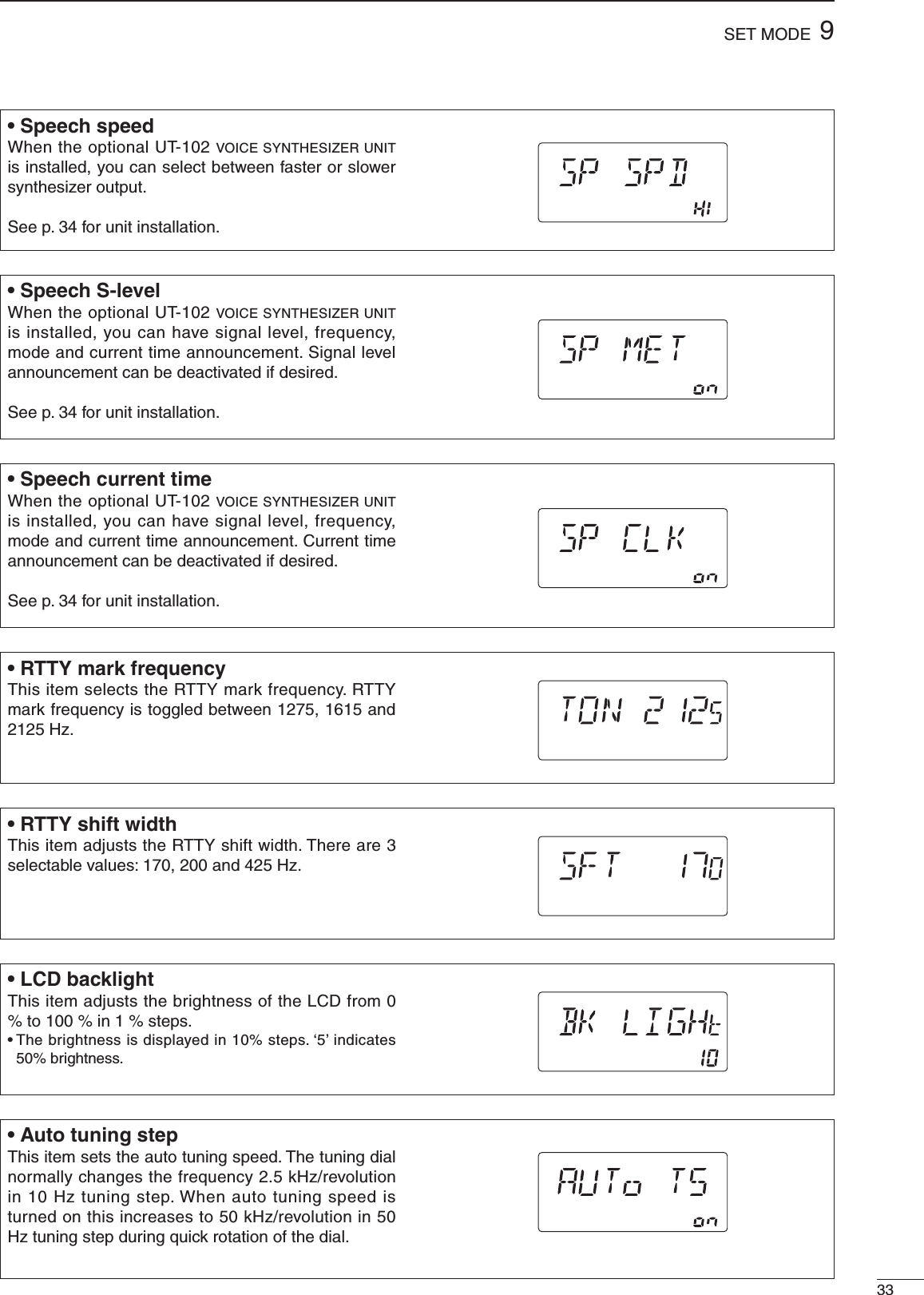
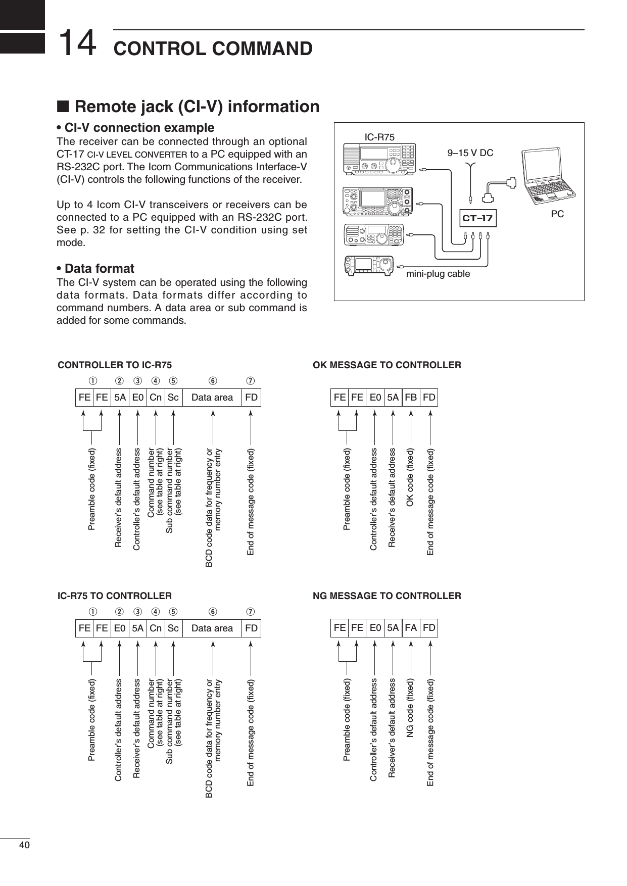
![329SET MODE• Recorder remoteThis item sets the [REC REMOTE] jack function ON or OFF.• CI-V addressTo distinguish equipment, each CI-V transceiver or receiver has its own Icom standard address in hexadecimal code. The IC-R75’s address is 5Ah.When 2 or more IC-R75’s are connected to an optional CT-17 CI-V LEVEL CONVERTER, rotate the tuning dial to select a different address for each IC-R75 in the range 01h to 7Fh.• CI-V baud rateThis item sets the data transfer rate. “3” (300 bps), “12” (1200 bps), “48” (4800 bps), “96” (9600 bps), “HI” (19200 bps) and “At” (automatic) are available.When “At” is selected, the baud rate is automatically set according to the connected controller or remote controller.• CI-V with IC-735When connecting the IC-R75 to the IC-735 for transceive operation, you must change the operating frequency data length to 4 bytes.• This item must be set to “ON” only when operating receiver with the IC-735.• Speech languageWhen the optional UT-102 VOICE SYNTHESIZER UNIT is installed, you can select between English and Japanese as the language.• “En” English announcement• “JP” Japanese announcementSee p. 34 for unit installation.• CI-V transceiveTransceive operation is possible with the IC-R75 connected to other Icom HF transceivers or receivers.When “on” is selected, changing the frequency, operating mode, etc. on the IC-R75 automatically changes those of connected transceivers (or receivers) and vice versa.](https://usermanual.wiki/ICOM-orporated/IC-R75.User-Manual/User-Guide-1145975-Page-36.png)
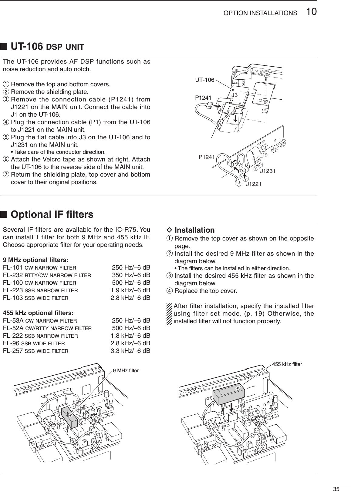
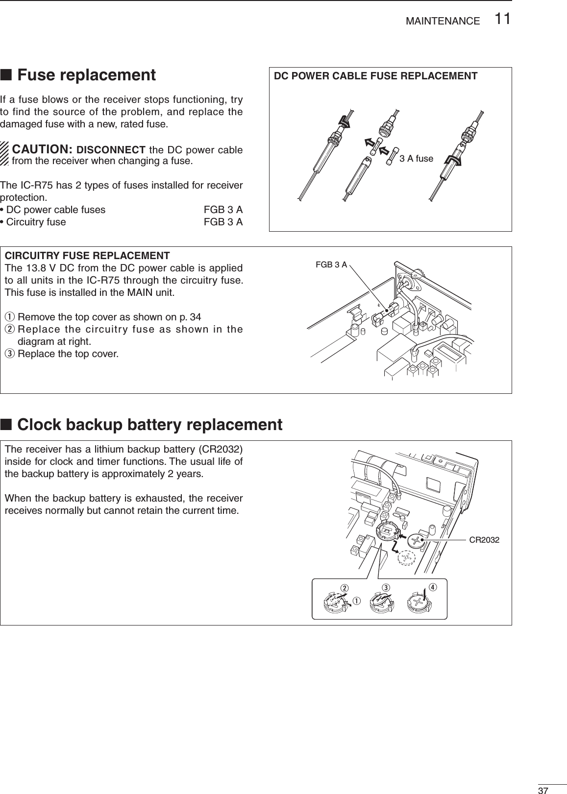
![1034OPTION INSTALLATIONS■ Opening the receiver’s caseFollow the case and cover opening procedures shown here when you want to install an optional unit or adjust an internal unit, etc. CAUTION: DISCONNECT the DC power cable from the receiver before performing any work on the receiver. Otherwise, there is danger of electric shock and/or equipment damage.q Remove the 2 screws from the left side of the receiver to remove an optional carrying handle, if necessary.w Remove the 4 screws from the top of the receiver and 4 screws from the sides, then lift up the top cover.e Remove the 2 screws from the bottom of the receiver, slide the cover backward, then remove the bottom cover.The UT-102 announces the received frequency, mode, S-meter level and current time in a clear, electronically-generated voice, in English (or Japanese).➥ Push [LOCK] for 2 sec. to announce the frequency, etc.q Remove the top cover as shown above.w Remove the protective paper attached to the bottom of the UT-102 to expose the adhesive strip.e Plug UT-102 into J1271 on the MAIN unit as shown at right.r Return the top cover to its original position.■ CR-282 high stability crystal unit By installing the CR-282, the total frequency stability of the receiver will be improved.q Remove the top cover as shown in the diagram above.w Remove 5 screws from the PLL unit, disconnect P1 from J491 (MAIN unit), then remove the PLL unit. e Remove the supplied internal crystal and replace with the CR-282.r Adjust the reference frequency at L2 using a frequency counter.t Return the PLL unit and top cover to their original positions.PLL unitMAIN unitCR-282InternalcrystalConnect a frequency counter here and adjust the frequency to 60.00000 MHz.L2PLL unit■ UT-102 voice synthesizer unit](https://usermanual.wiki/ICOM-orporated/IC-R75.User-Manual/User-Guide-1145975-Page-38.png)
![■ Resetting the CPU Resetting CLEARS all programmed contents in memory channels and returns programmed values in set mode to their defaults.When first applying power or when the function seems to be displaying erroneous information, reset the CPU as follows:q Make sure receiver power is OFF.w While pushing [UP Y] and [Z DN], push [POWER] to turn power ON. • The internal CPU is reset. • The receiver displays its initial VFO frequencies when resetting is complete.1136MAINTENANCE■ TroubleshootingThe following chart is designed to help you correct problems which are equipment malfunctions.If you are not able to locate the cause of a problem or solve it through the use of this chart, contact your nearest Icom Dealer or Service Center.[POWER] [ZDN] [UPY]PROBLEM POSSIBLE CAUSE SOLUTION REF.POWERPower does not come onwhen the [POWER] switchis pushed.• DC power cable is improperly connected.• Fuse is blown.• Reconnect the DC power cable correctly.• Check for the cause, then replace the fuse witha spare one.(Fuses are installed in the DC power cableand the internal MAIN unit.)—p. 37RECEIVENo sound comes from thespeaker.• Volume level is too low.• The squelch is closed.•Rotate [AF] clockwise to obtain a suitablelistening level.• Rotate [RF/SQL] to 12 o’clock position to openthe squelch.p. 2p. 14Sensitivity is low. • The antenna is not connected properly.• The antenna for another band is selected.• The attenuator is activated.• Reconnect to the antenna connector.•Select an antenna suitable for the operatingfrequency.• Push [ATT] to turn the function OFF.—p. 16p. 16Receive audio is distorted. • The operating mode is not selected correctly.• PBT function is activated.• Noise blanker function is activated.• Preamp is activated.• The optional noise reduction is activated andthe [NR] level is set too high.• Select a suitable operating mode.• Set [TWIN PBT] to the center position.• Push [NB] to turn the function OFF.• Push [P.AMP] once or twice to turn the functionOFF.• Push [NR] to turn the function OFF.p. 14p. 15p. 15p. 16p. 20SCANProgrammed scan doesnot stop.• Squelch is open.• [RF/SQL] is assigned to RF gain control andsquelch is open.• Set [RF/SQL] to the threshold point.• Reset [RF/SQL] control assignment and set it tothe threshold point.p. 14pgs. 14, 30Programmed scan doesnot start.• The same frequencies have been programmedin scan edge memory channels P1 and P2.•Program different frequencies in scan edgememory channels P1 and P2.p. 22Memory scan does notstart.•2 or more memory channels have not beenprogrammed.• Program 2 or more memory channels. p. 22Select memory scan doesnot start.•2 or more memory channels have not beendesignated as select channels.• Designate 2 or more memory channels as selectchannels for the scan.p. 26DISPLAY“F.AGC” flashes in thefunction display.• A scan or band scope function is activated viaan optional RS-R75 remote control software.• If these functions are not in use, push [AGC] todeactivate the function.—The displayed frequencydoes not change properly.• The dial lock function is activated.• The internal CPU has malfunctioned.• Push [LOCK] to deactivate the function.• Reset the CPU.p. 13Seebelow.](https://usermanual.wiki/ICOM-orporated/IC-R75.User-Manual/User-Guide-1145975-Page-40.png)
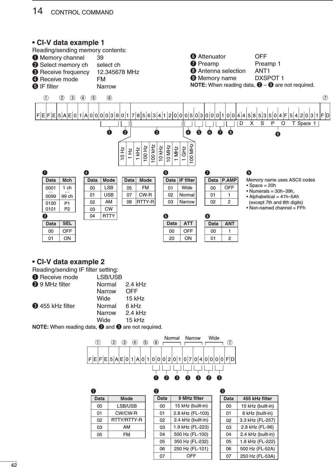
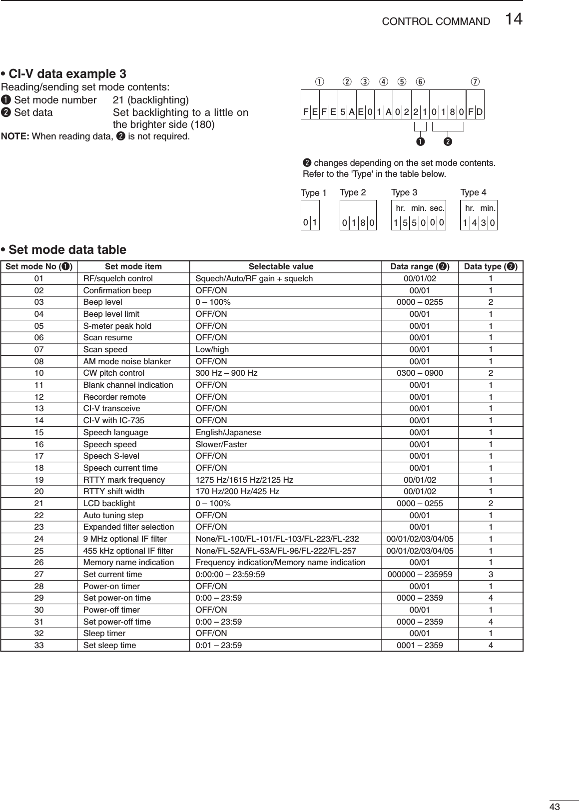
![4114CONTROL COMMAND• Command tableSub commandCommand Description—00 Send frequency dataSame as command 06Same as command 0601 Send mode data—02 Read band edge frequencies—03 Read operating frequency04 Read operating mode—05 Set frequency data00*101*102*103*104*105*107*108*1Set LSBSet USBSet AMSet CWSet RTTYSet FMSet CW-RSet RTTY-R06*1Add 00, 01 or 02 for selecting wide, normal or narrow filter, respectively. ——07 Select VFO mode0001 – 0101*2Select memory modeSelect memory channel*2P1=0100, P2=010108—09 Memory write—0A Memory to VFO—0B Memory clear000102042223B0B1D0D30EScan stopProgrammed/memory scan startProgrammed scan startAuto memory write scan startMemory scan startSelect memory scan startSet as non-select channelSet as select channelSet scan resume OFFSet scan resume ON0001020304050607080910111010 Hz (1 Hz) tuning step100 Hz tuning step1 kHz tuning step5 kHz tuning step6.25 kHz tuning step9 kHz tuning step10 kHz tuning step12.5 kHz tuning step20 kHz tuning step25 kHz tuning step100 kHz tuning step1 MHz tuning stepSub commandCommand Description002011 Attenuator OFFAttenuator ONSelect [ANT1]Select [ANT2]000112Announce with voice synthesizer(00=all data; 01=frequency and S-meter level; 02=receive mode)00010201 + level data13[CW PITCH] setting (0000=low pitch to 0255=high pitch)1415161819Read squelch conditionRead S-meter level01020212224041Set preamp (00=OFF; 01=preamp 1; 02=preamp 2)Set AGC time constant (00=OFF; 01=S-fast; 02=fast; 03=slow)Set noise blanker (00=OFF; 01=ON)Set optional noise reduction (00=OFF; 01=ON)Set optional auto notch (00=OFF; 01=ON)Turn the receiver power ONTurn the receiver power OFFRead the receiver IDSend/read memory contents(See example 1 on p. 42)Send/read IF filter setting(See example 2 on p. 42)Send/read set mode contents(See example 3 on p. 43)0001001A 00 + data01 + data02 + data[AF] level setting (0000=max. CCW to 0255=max. CW)[RF] level setting (0000=max. CCW to 0255=11 o’clock)[SQL] level setting (0000=11 o’clock to 0255=max. CW)[NR] level setting (0000=min. to 0255=max.)Inside [TWIN PBT] setting (0000=max. CCW, 0128=center, 0255=max. CW)Outside [TWIN PBT] setting (0000=max. CCW, 0128=center, 0255=max. CW)09 + level data08 + level data07 + level data06 + level data03 + level data02 + level data](https://usermanual.wiki/ICOM-orporated/IC-R75.User-Manual/User-Guide-1145975-Page-45.png)