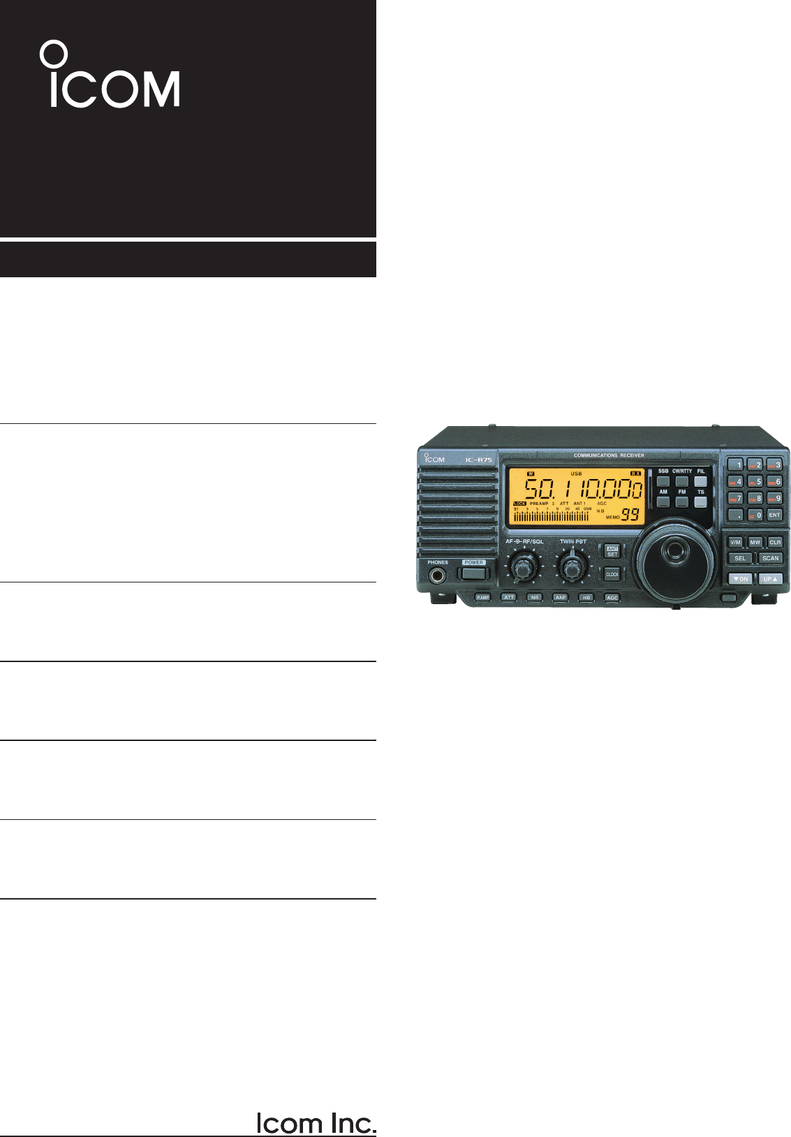
ICOM orporated IC-R75 Scanning Receiver User Manual
ICOM Incorporated Scanning Receiver
Contents
- 1. manual
- 2. User Manual
User Manual
INSTRUCTION MANUAL
COMMUNICATIONS RECEIVER
iR75

i
IMPORTANT
READ THIS INSTRUCTION MANUAL CAREFULLY before
attempting to operate the receiver.
SAVE THIS INSTRUCTION MANUAL. This manual contains
important safety and operating instructions for the IC-R75.
EXPLICIT DEFINITIONS
TRADEMARKS
Icom, Icom Inc. and the Icom logo are registered trademarks of Icom
Incorporated (Japan) in Japan, the United States, the United Kingdom,
Germany, France, Spain, Russia and/or other countries.
Microsoft and Windows are registered trademarks of Microsoft Corporation
in the United States and other countries.
Pentium is a registered trademark of Intel Corporation.
All other products or brands are registered trademarks or trademarks of
their respective holders.
WORD DEFINITION
R WARNING Personal injury, fire hazard or electric shock may
occur.
CAUTION Equipment damage may occur.
NOTE If disregarded, inconvenience only. No risk of personal
injury, fire or electric shock.

RWARNING NEVER apply AC to the [DC13.8V]
jack on the receiver rear panel. This could cause a fire
or ruin the receiver.
RWARNING NEVER apply more than 16 V DC,
such as a 24 V battery, to the [DC13.8V] jack on the
receiver rear panel. This could cause a fire or ruin the
receiver.
RWARNING NEVER let metal, wire or other
objects touch any internal part or connectors on
the rear panel of the receiver. This may result in an
electric shock.
NEVER expose the receiver to rain, snow or any
liquids.
DO NOT use or place the receiver in areas with
temperatures below –10°C (+14°F) or above +60°C
(+140°F). Be aware that temperatures on a vehicle’s
dashboard can exceed 80°C (+176°F), resulting in
permanent damage to the receiver if left there for
extended periods.
DO NOT place the receiver in excessively dusty
environments or in direct sunlight.
DO NOT place the receiver against walls or putting
anything on top of the receiver. This will obstruct heat
dissipation.
Place unit in a secure place to avoid inadvertent use by
children.
During mobile operation, DO NOT operate the receiver
without running the vehicle’s engine. When receiver
power is ON and your vehicle’s engine is OFF, the
vehicle’s battery will soon become exhausted.
Make sure the receiver power is OFF before starting
the vehicle. This will avoid possible damage to the
receiver by ignition voltage spikes.
For U.S.A only
CAUTION: Changes or modifications not expressly
approved by the party responsible for compliance
could void the user's authority to operate the
equipment.
PRECAUTIONS
ii
FOR CLASS B UNINTENTIONAL RADIATORS
This equipment has been tested and found to comply with the limits for a Class B digital device, pursuant to part
15 of the FCC Rules. These limits are designed to provide reasonable protection against harmful interference
in a residential installation. This equipment generates, uses and can radiate radio frequency energy and, if not
installed and used in accordance with the instructions, may cause harmful interference to radio communications.
However, there is no guarantee that interference will not occur in a particular installation. If this equipment does
cause harmful interference to radio or television reception, which can be determined by turning the equipment off
and on, the user is encouraged to try to correct the interference by one or more of the following measures:
• Reorient or relocate the receiving antenna.
• Increase the separation between the equipment and receiver.
• Connect the equipment into an outlet on a circuit different from that to which the receiver is connected.
• Consult the dealer or an experienced radio/TV technician for help.
Versions of the IC-R75 which display the “CE” symbol on the serial number label comply with the
European harmonised standard ETS300 684 (EMC product standard for Commercially Available
Amateur Radio Equipment).
iii
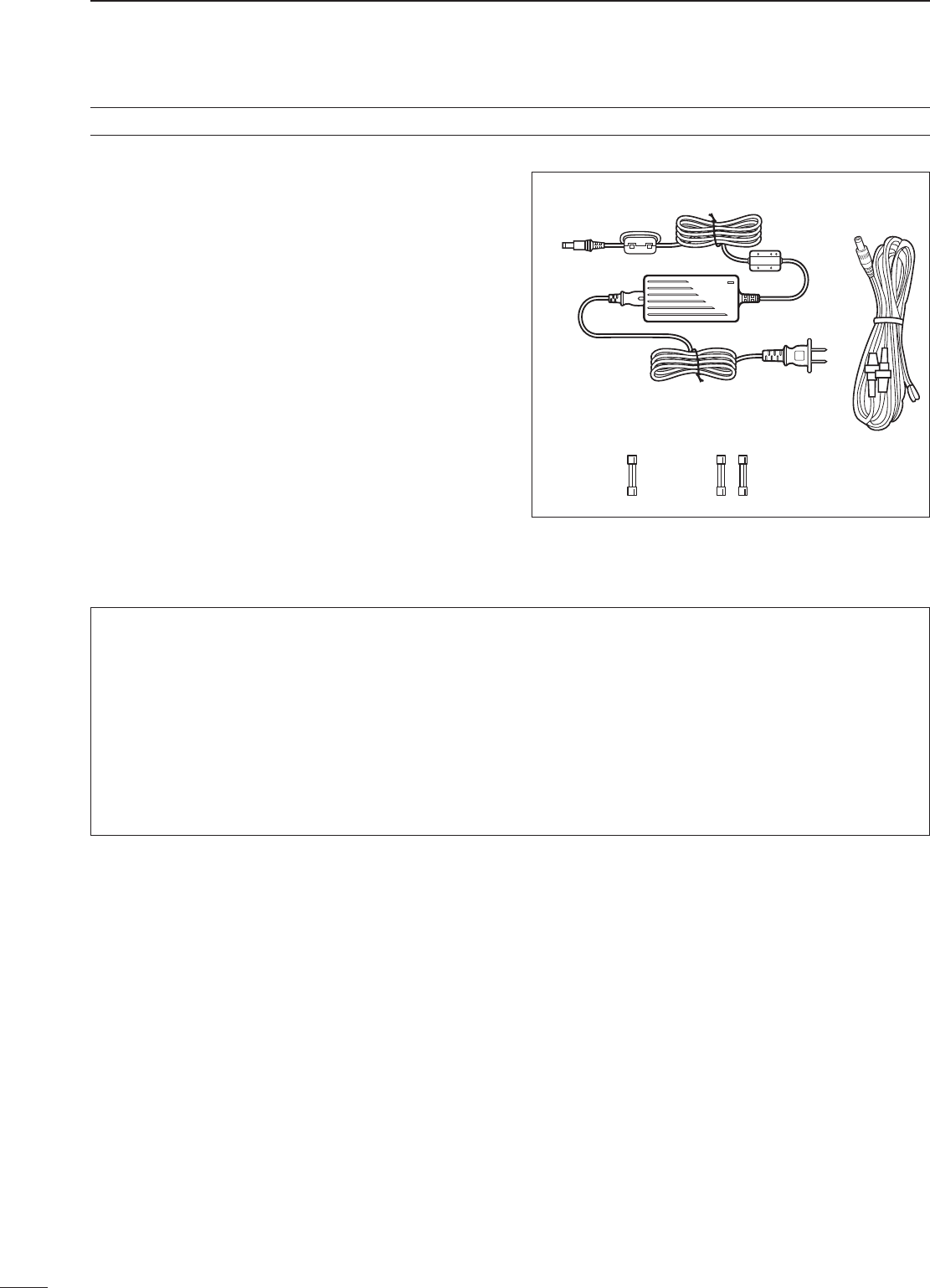
The receiver comes with the following accessories.
Qty.
q AC adapter (AD-55/A/S/V†)* ................................ 1
w DC power cable (OPC-869)* ............................... 1
e Fuse (FGB 3 A; internal use) .............................. 1
r Fuse (FGB 3 A; for DC cable)* ............................ 2
* Either AC adapter + 1 fuse (q, e) or DC power cable + 3
fuses (w, e, r) are supplied depending on versions.
† The AD-55, AD-55A, AD-55S and AD-55V have different
shapes.
SUPPLIED ACCESSORIES
q w
e r
INFORMATION
A switching type AC adapter includes a switching regulator. The receiver could receive switching noise from the
adapter’s switching regulator circuit. Depending on the usage environment, it tends to happen in AM reception,
especially around 7 to 10 MHz. If it causes interference, please try some of the following to reduce the noise.
• Ground the receiver.
• When another AC powered equipment is connected to the receiver, plug the AC adapter into a different AC
outlet than the equipment.
• Keep the AC adapter as far away from the receiver’s antenna and any metal objects as possible.
• Attach an AC line filter to the AC adapter.

1
1
TABLE OF CONTENTS
IMPORTANT ............................................................. i
EXPLICIT DEFINITIONS .......................................... i
TRADEMARKS ......................................................... i
PRECAUTIONS ........................................................ ii
SUPPLIED ACCESSORIES .................................... iii
1 TABLE OF CONTENTS ....................................... 1
2 PANEL DESCRIPTION .................................. 2 – 6
■ Front panel ....................................................... 2
■ Function display ............................................... 5
■ Rear panel ........................................................ 6
3 INSTALLATION AND CONNECTIONS ....... 7 – 10
■ Grounding ........................................................ 7
■ Receiver stand ................................................. 7
■ Optional bracket and carrying handle ............... 7
■ Connections ..................................................... 8
■ Antenna connection ......................................... 9
■ Tape recorder connections ............................... 9
■ Transceive function ........................................... 9
■ FSK and AFSK (SSTV) connections .............. 10
■ Connecting to a PC ........................................ 10
4 FREQUENCY SETTING ............................ 11 – 13
■ Read me first .................................................. 11
■ Using the keypad ............................................ 11
■ Frequency setting ........................................... 12
■ Dial lock function ............................................ 13
5 RECEIVE FUNCTIONS ............................. 14 – 20
■ Mode selection ............................................... 14
■ Squelch and RF gain ...................................... 14
■ Twin PBT operation ........................................ 15
■ Noise blanker ................................................. 15
■ Preamp ........................................................... 16
■ Attenuator ....................................................... 16
■ AGC time constant ......................................... 16
■ Antenna selection ........................................... 16
■ CW reverse mode .......................................... 17
■ CW pitch control ............................................. 17
■ RTTY reverse mode ....................................... 17
■ Filter selection ................................................ 18
■ Filter set mode ............................................... 19
■ Optional noise reduction function ................... 20
■ Optional auto notch function .......................... 20
6 MEMORY OPERATION ............................. 21 – 24
■ Memory channels ........................................... 21
■ Memory channel selection ............................. 21
■ Memory channel programming ...................... 22
■ Frequency transferring ................................... 23
■ Memory names .............................................. 24
■ Memory clearing ............................................ 24
7 SCANS ...................................................... 25 – 27
■ Scan types ..................................................... 25
■ Preparation ..................................................... 25
■ Programmed scan operation .......................... 26
■ Memory/select memory scan operation ......... 26
■ Setting select memory channels .................... 26
■ Priority watch operation .................................. 27
■ Auto memory write scan operation ................. 27
8 CLOCK AND TIMERS ............................... 28 – 29
■ Setting the current time .................................. 28
■ Setting power-on time .................................... 28
■ Setting power-off time .................................... 29
■ Setting sleep timer period .............................. 29
9 SET MODE ................................................ 30 – 33
■ Set mode description ..................................... 30
10 OPTION INSTALLATIONS ..................... 34 – 35
■ Opening the receiver’s case ........................... 34
■ CR-282 HIGH STABILITY CRYSTAL UNIT ......... 34
■ UT-102 VOICE SYNTHESIZER UNIT ................. 34
■ UT-106 DSP UNIT ............................................ 35
■ Optional IF filters ............................................ 35
11 MAINTENANCE ...................................... 36 – 37
■ Troubleshooting .............................................. 36
■ Resetting the CPU ......................................... 36
■ Fuse replacement .......................................... 37
■ Clock backup battery replacement ................. 37
12 SPECIFICATIONS ........................................... 38
13 OPTIONS ........................................................ 39
14 CONTROL COMMAND ........................... 40 – 43
■ Remote jack (CI-V) information ...................... 40
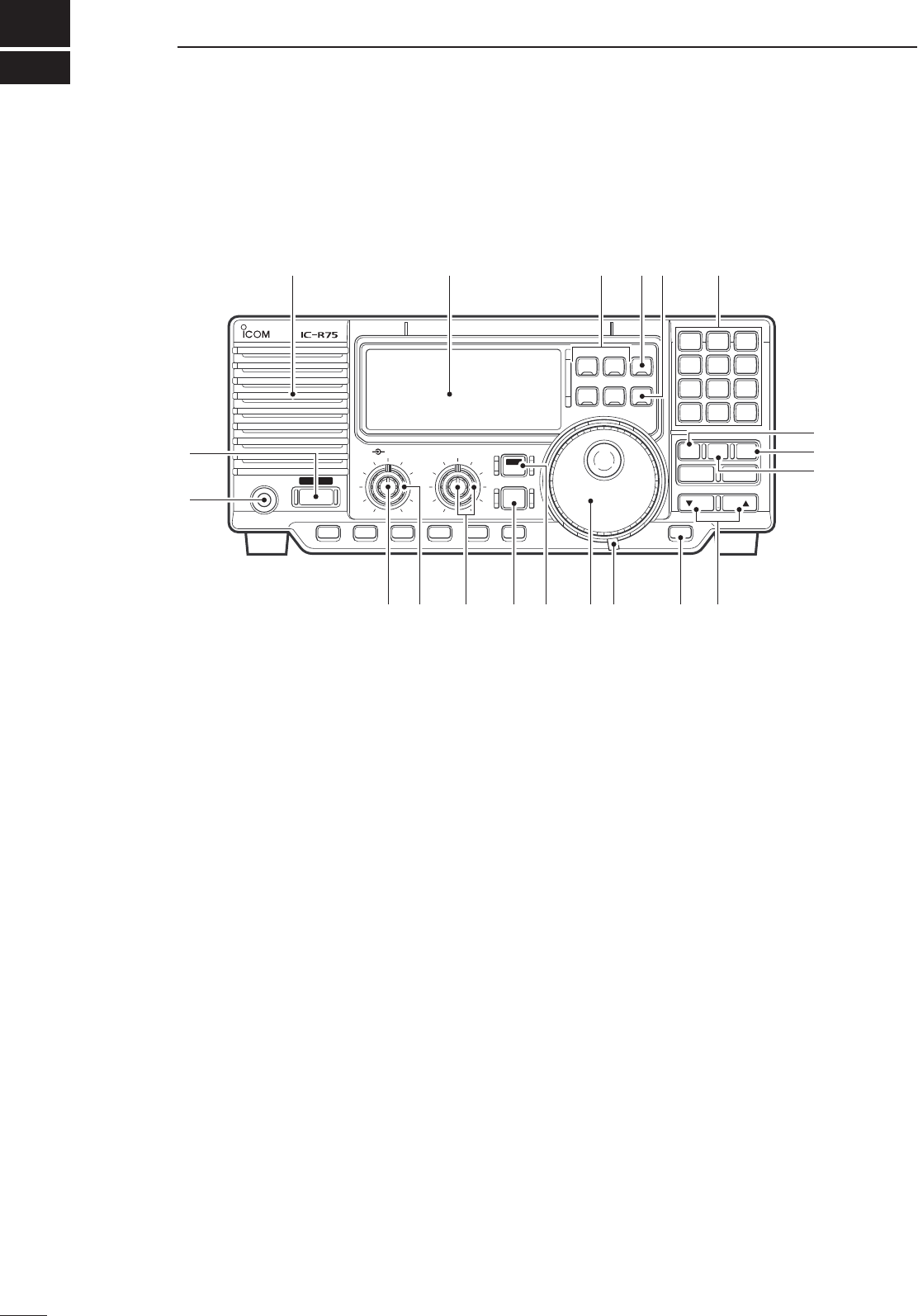
■ Front panel
q POWER SWITCH [POWER]
➥ Push momentarily to turn power ON.
• Turn the optional DC power supply ON in advance.
➥ Push for 2 sec. to turn power OFF.
w HEADPHONE JACK [PHONES] (p. 8)
Accepts headphones.
• When headphones are connected, the internal speaker
or connected external speaker does not function.
e AF CONTROL [AF] (inner control)
Varies the audio output level from the speaker.
r RF GAIN/SQUELCH CONTROL [RF/SQL]
(outer control; pgs. 14, 30)
Adjusts the squelch threshold level. The squelch
removes noise output from the speaker (closed
condition) when no signal is received.
• The squelch is particularly effective for FM. It is also
available for other modes.
• The control can be set as the squelch plus RF gain
controls or squelch control only (RF gain is fixed at
maximum) in set mode.
t PASSBAND TUNING CONTROLS [TWIN PBT]
(p. 15)
Adjust the receiver’s “passband width” of the 455
kHz and 9 kHz IF filters for the inner and outer
controls, respectively.
• Set to the center positions when not in use.
y CLOCK MODE SWITCH [CLOCK] (p. 28)
Toggles between frequency indication and clock
indication when pushed.
u ANTENNA SELECTOR/SET MODE SWITCH
[ANT/SET] (pgs. 16, 30)
➥ While in a frequency indication, enters set mode
when pushed.
➥ While in a frequency indication, toggles between
the antenna 1 and 2 connectors when pushed
for 2 sec.
➥ While in the clock indication, enters time setting
condition when pushed for 2 sec.
➥ While in a timer indication, toggles the timer ON
or OFF when pushed.
i TUNING DIAL
Changes the displayed frequency, selects set
mode items, etc.
o TUNING DIAL TENSION LATCH
Adjusts the tension of the tuning dial.
!0 LOCK/SPEECH SWITCH [LOCK] (pgs. 13, 34)
➥ Toggles the frequency lock function ON and
OFF.
➥ Announces the selected readout frequency
when an optional UT-102 is installed and when
pushed for 2 sec.
2
2
PANEL DESCRIPTION
FIL
TS
CW/RTTY
FM
SSB
AM
PHONES POWER
RF/ SQL TWIN PBTAF
COMMUNICATIONS RECEIVER
DN UP
1 2
ABC
3
DEF
4
GHI
5
JKL
6
MNO
7
PRS
8
TUV
9
WXY
.0
QZ
ENT
V/M MW
SEL SCAN
CLR
LOCK
AGCNBANFNRATT
P.AMP
SET
CLOCK
ANT
Function display (p. 5)Speaker
q
w
e r t y i o !
0
!
1
!3
!4
!5!6!7!8
!2
u

3
2
PANEL DESCRIPTION
!1 MEMORY CHANNEL UP/DOWN SWITCHES
[√ DN]/[UP ∫] (p. 21)
➥ Select a memory channel.
➥ Select a set mode contents while in set mode.
➥ Select a timer or time indication while in clock
indication.
➥ Select a filter set mode contents while in filter
set mode.
!2 MEMORY WRITE SWITCH [MW] (pgs. 22, 27)
➥ Stores the displayed frequency and operating
mode into the selected memory channel when
pushed for 2 sec.
➥ Toggles the programmed scan and auto
memory write scan when pushed.
!3 CLEAR SWITCH [CLR] (p. 24)
➥ Clears the input digits while inputting a
frequency or memory channel number.
➥ Clears the selected memory channel contents
when pushed for 2 sec. in memory mode.
• This switch does not function in VFO mode.
!4 VFO/MEMORY SWITCH [V/M] (pgs. 21, 23)
➥ Toggles the operating mode between VFO mode
and memory mode when pushed.
➥ Selects a memory channel for inputting a
memory channel number when pushed.
➥ Transfers the memory contents to VFO when
pushed for 2 sec.
!5 KEYPAD (pgs. 11, 21)
The keypad can be used for several functions as
below:
• Keypad then [ENT]
— Direct frequency input.
• Keypad then [V/M]
— Memory channel selection.
• [ENT] then keypad in memory name indication
mode
— Alphanumeric input for memory name, etc.
!6 QUICK TUNING STEP SWITCH [TS] (pgs. 12, 13)
➥ Selects a quick tuning step or turns the quick
tuning step OFF.
• While the quick tuning indicator (
√
) is displayed, the
frequency can be changed in kHz or MHz steps.
➥ While the quick tuning step is OFF, turns the 1
Hz step ON and OFF when pushed for 2 sec.
• 1 Hz indication appears and the frequency can be
changed in 1 Hz steps.
➥ While the kHz quick tuning step is selected,
enters tuning step set mode when pushed for 2
sec.
➥ While the memory name indication is selected
in memory mode, pushing this switch shows the
operating frequency; and rotating the tuning dial
while pushing this switch changes the frequency
temporally.
!7 FILTER SWITCH [FIL] (pgs. 18, 19)
➥ Push momentarily to toggle between the pre-
programmed normal, wide and narrow IF filters
for the selected operating mode.
➥ Push for 2 sec. to enter filter set mode.
!8 MODE SWITCHES [SSB]/[CW/RTTY]/[AM]/[FM]
(p. 14)
Select an operating mode.
• Push [SSB] to toggle between LSB and USB.
• Push [CW/RTTY] to toggle between CW and RTTY.
• Push [CW/RTTY] for 2 sec. to toggle between CW and
CW reverse or RTTY and RTTY reverse.
• Push [AM] to select AM.
• Push [FM] to select FM.
4
2PANEL DESCRIPTION
■ Front panel (continued)
!9 PREAMP SWITCH [P.AMP] (p. 16)
Push to toggle between preamp-1 and preamp-2
or turn the preamp OFF.
@0 ATTENUATOR SWITCH [ATT] (p. 16)
Push to toggle the 20 dB attenuator function ON
and OFF.
@1 NOISE REDUCTION SWITCH [NR] (p. 20)
➥ Toggles the optional noise reduction function
ON and OFF when pushed. Functions in SSB,
CW and RTTY modes. An optional UT-106 DSP
UNIT is required.
➥ Enters noise reduction level set mode when
pushed for 2 sec. An optional UT-106 DSP UNIT is
required.
@2 AUTOMATIC NOTCH FILTER SWITCH [ANF]
(p. 20)
Push to turn the optional automatic notch filter for
receiving AM signals ON and OFF. An optional
UT-106 DSP UNIT is required.
@3 NOISE BLANKER SWITCH [NB] (p. 15)
Toggles the noise blanker ON and OFF. The noise
blanker reduces pulse-type noise such as that
generated by automobile ignition systems. This
function is not effective for FM, or non pulse-type
noise.
@4 AGC SWITCH [AGC] (p. 16)
➥ Toggles the AGC (Automatic Gain Control) time
constant fast and slow when pushed.
➥ Toggles the AGC function ON and OFF when
pushed for 2 sec.
@5 SELECT SWITCH [SEL] (pgs. 24, 26)
➥ Toggles the select memory setting ON and OFF
when pushed in memory mode.
➥ Toggles the memory name indication ON and
OFF when pushed for 2 sec. in memory mode.
@6 SCAN SWITCH [SCAN] (p. 25)
➥ Push momentarily to start/stop the programmed
scan in VFO mode.
➥ Push momentarily to start/stop the memory
scan in memory mode.
➥ Push for 2 sec. to start the priority watch in VFO
mode.
• Push [SCAN] again to cancel the priority watch.
FIL
TS
CW/RTTY
FM
SSB
AM
PHONES POWER
RF/ SQL TWIN PBTAF
COMMUNICATIONS RECEIVER
DN UP
1 2
ABC
3
DEF
4
GHI
5
JKL
6
MNO
7
PRS
8
TUV
9
WXY
.
0
QZ
ENT
V/M MW
SEL SCAN
CLR
LOCK
AGCNBANFNRATT
P.AMP
SET
CLOCK
ANT
Function display (p. 5)
!
9
@
0
@
1
@
2
@
3
@
4
@6
@5
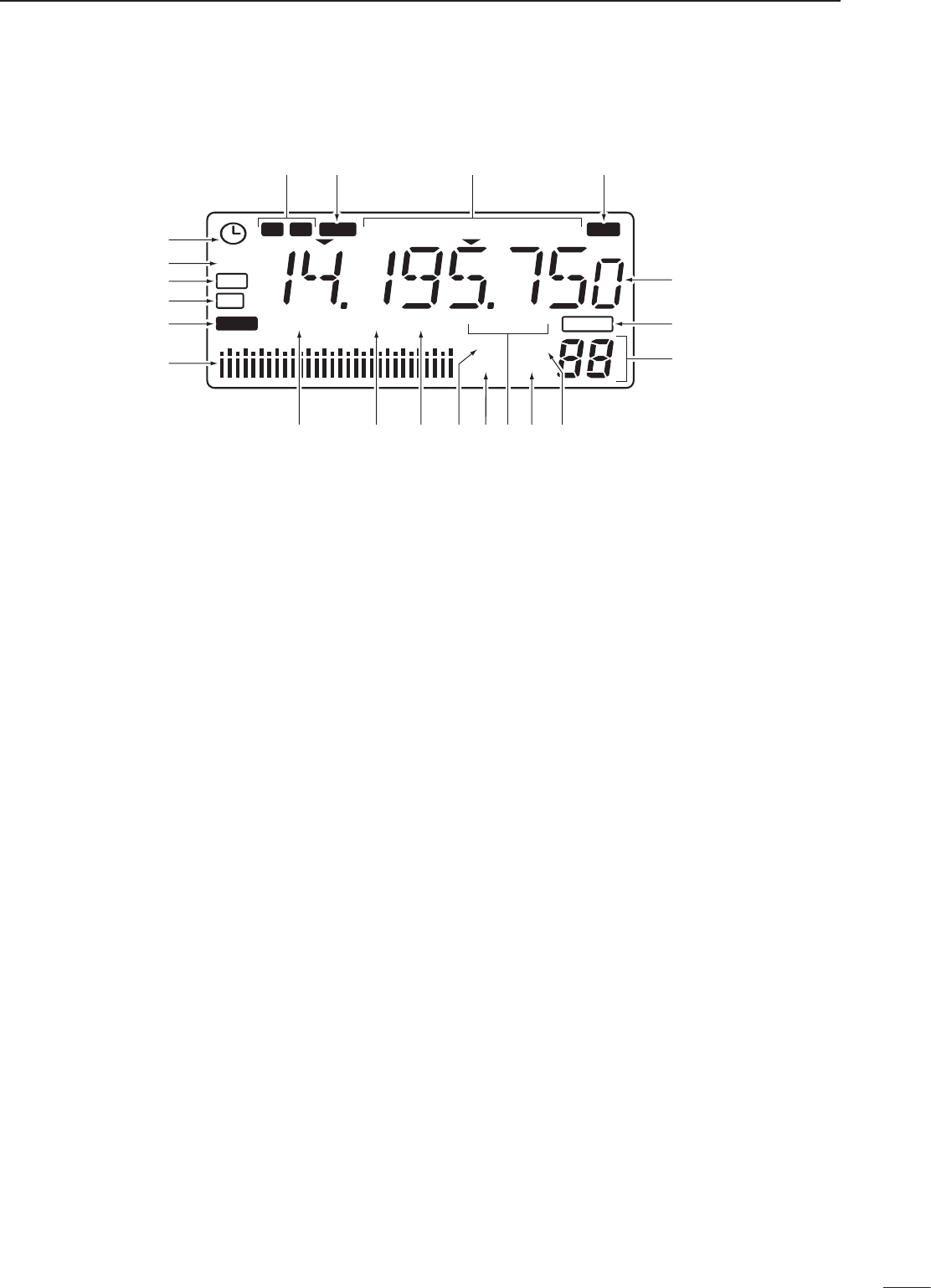
■ Function display
q TIMER INDICATOR (p. 28)
Appears when power on/off timer or sleep timer is
in use.
w DSP UNIT INDICATOR (p. 35)
Appears when an optional UT-106 DSP UNIT is
installed.
e AUTOMATIC NOTCH FILTER INDICATOR (p. 20)
Appears when the optional automatic notch filter is
in use.
r NOISE REDUCTION INDICATOR (p. 20)
Appears when the optional noise reduction
function is in use.
t LOCK INDICATOR (p. 13)
Appears when the dial lock function is in use.
y SIGNAL METER
➥ Shows the relative receive signal strength.
➥ Shows the S-meter squelch level when used.
u PREAMP INDICATOR (p. 16)
Appears when antenna preamp-1 or preamp-2 is
in use.
i ATTENUATOR INDICATOR (p. 16)
Appears when the attenuator function is in use.
o ANTENNA INDICATORS (p. 16)
Indicate which antenna connector is in use.
!0 NOISE BLANKER INDICATOR (p. 15)
Appears when the noise blanker function is in use.
!1 SCAN INDICATOR (p. 25)
➥ Appears when scan or priority watch is activated.
➥ Flashes when scan or priority watch is paused.
!2 AGC INDICATORS (p. 16)
➥ “AGC” appears when slow AGC time constant is
selected.
➥ “F.AGC” appears when fast AGC time constant
is selected.
➥ “AGC OFF” appears when the AGC function is
turned OFF.
➥ “F.AGC” blinks while scanning or while using
band scope via an optional RS-R75.
!3 MEMORY MODE INDICATOR (p. 21)
Indicates memory mode is selected.
!4 VFO MODE INDICATOR
Indicates VFO mode is selected.
!5 MEMORY CHANNEL NUMBER READOUT
(p. 21)
➥ Shows the selected memory channel number.
➥ “S” appears when the displayed memory
channel is designated as a select memory
channel.
!6 BLANK MEMORY INDICATOR
Shows that the displayed memory channel is not
programmed.
• This indicator appears both in VFO and memory modes.
!7 FREQUENCY READOUT
Shows the operating frequency.
!8 RECEIVE INDICATOR
Appears while receiving a signal or when the
squelch is open.
!9 MODE INDICATORS (p. 14)
Indicate the selected operating mode.
@0 REVERSE MODE INDICATOR (p. 17)
Indicates a reverse operating mode is selected.
@1 WIDE/NARROW FILTER INDICATORS (p. 18)
➥ “ç” appears when the wide IF filter is selected.
➥ “ã” appears when the narrow IF filter is
selected.
5
2
PANEL DESCRIPTION
DSP
BLANKBLANK
S
RTTY
PREAMP
TIMER
S1 3 57920 40 60
dB
F.AGC OFFANTATT
LSBUSBCWS
-
AMFM
REV
NW
ANF
NR
LOCK
R X
MEMO
SCAN
N B
VFO
1 12 2
q
w
e
r
t
y
u i o !0 !1 !2 !3 !4
!5
!6
!7
!8!9@0@1
6
2PANEL DESCRIPTION
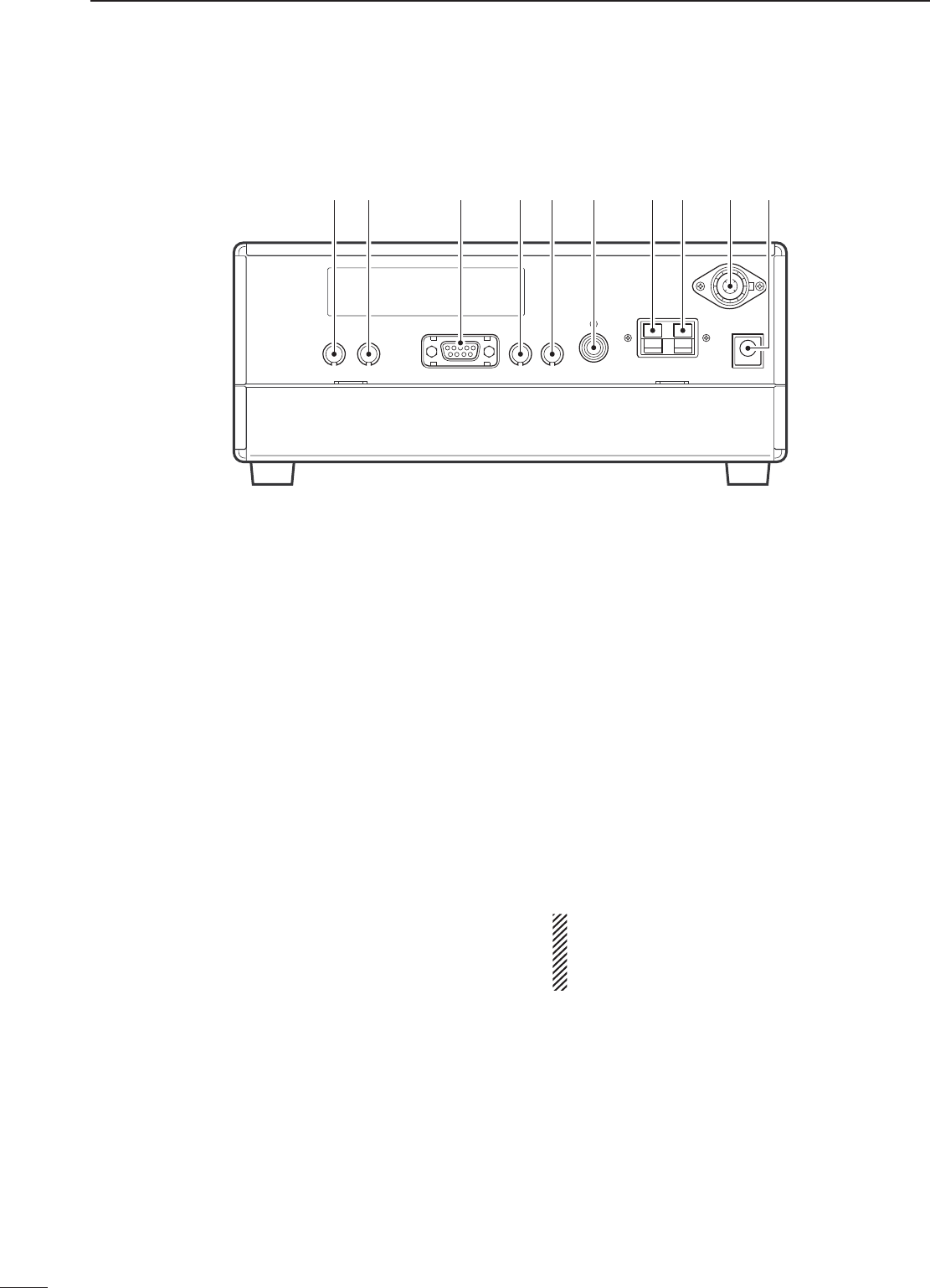
■ Rear panel
q RECORDER REMOTE JACK [REC REMOTE]
Controls the running of a tape recorder for
recording. Connects to the REMOTE jack on a
tape recorder.
• This function can be turned OFF in set mode. (p. 32)
w RECORDER JACK [REC]
Outputs receive audio signals. Connects to the
AUX or LINE IN jack on a tape recorder.
e RS-232C CONNECTOR [RS-232C]
Connects an RS-232C cable. An RS-232C cable
can be used to connect the receiver to a PC. In this
way commands can be sent to the receiver via the
PC.
r CI-V REMOTE CONTROL JACK [REMOTE]
Allows connection to an Icom CI-V system
transceiver or another receiver for the transceive
function. Also connects to a PC with several
receivers for command control via an optional
CT-17 CI-V LEVEL CONVERTER.
t EXTERNAL SPEAKER JACK [EXT SP]
Connects an 8 Ω external speaker, if desired.
• When an external speaker is connected, the internal
speaker does not function.
y MUTE CONTROL JACK [MUTE]
Mutes audio outputs and attenuates the receive
signal input when grounded. Used for CI-V
transceive operation with a transceiver.
u GROUND TERMINAL [GND] (p. 7)
Connects the black terminal to ground.
i ANTENNA 2 TERMINAL [ANT 2] (p. 9)
Connects the red terminal to a 500 Ω long wire
antenna.
o ANTENNA 1 CONNECTOR [ANT 1] (p. 9)
Connects a 50 Ω antenna with a PL-259 connector
and a 50 Ω coaxial cable.
!0 DC POWER JACK [DC 13.8V] (p. 8)
➥ Connects the supplied AC adapter for versions
with an AC adapter.
➥ Connects to a 13.8 V DC power source using
the supplied DC cable for versions without an
AC adapter.
• Current of 1.5 A or greater is required.
DO NOT use a cigarette lighter socket as a
power source when operating in a vehicle. The
plug may cause voltage drops and ignition noise
may be superimposed onto received audio.
q w r t y u ie o !0
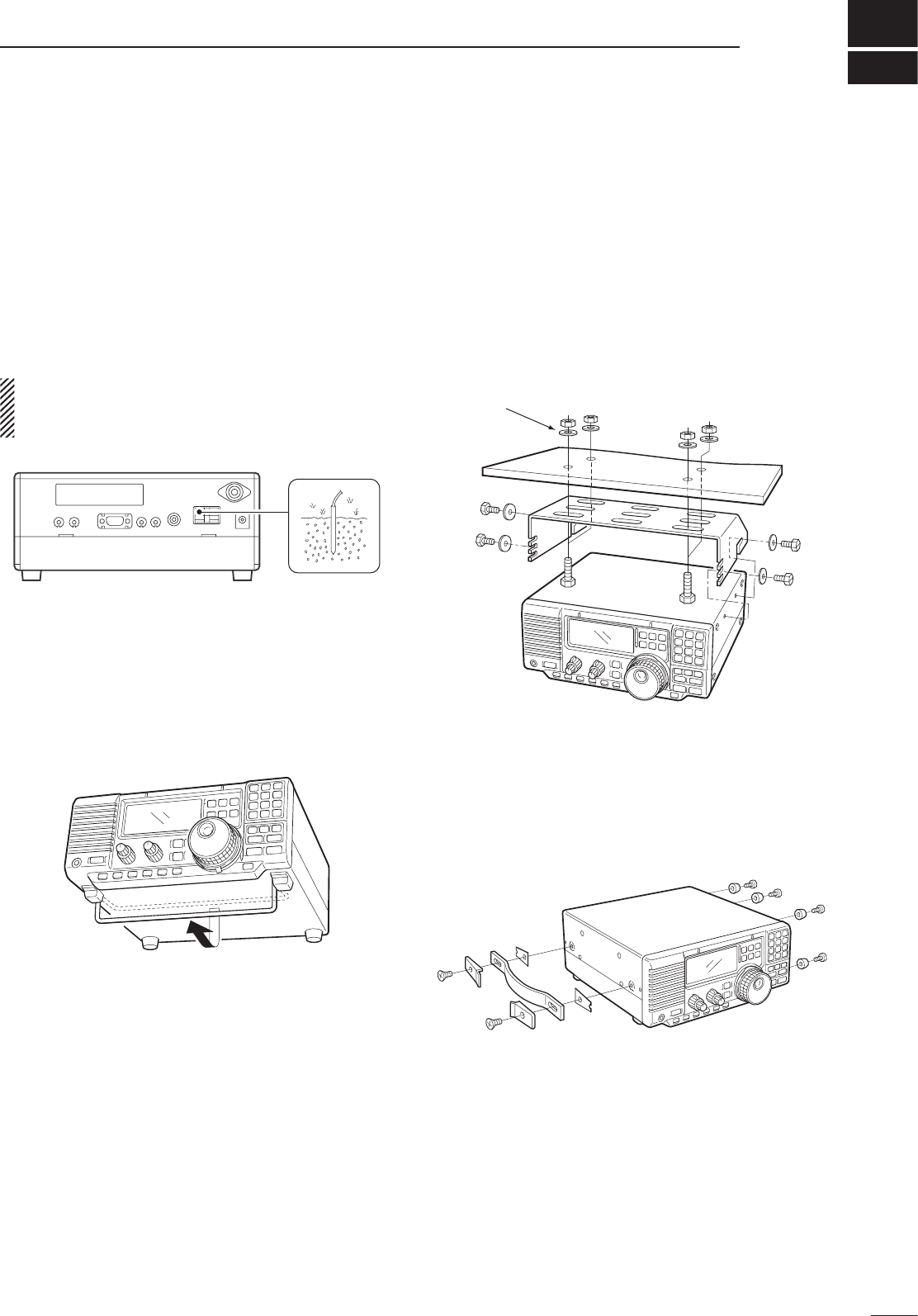
■ Grounding
To prevent accidents involving electricity and
interference from transceivers, ground the receiver
through the [GND] terminal on the rear panel.
For best results, connect a heavy gauge wire or strap
to a long earth-sunk copper rod. Make the distance
between the [GND] terminal and ground as short as
possible.
R WARNING: NEVER connect the [GND]
terminal to a gas or electric pipe, since the connec-
tion could cause an explosion or electric shock.
■ Receiver stand
The base of the receiver has an adjustable stand
for desktop use. Set the stand to one of two angles
depending on your operating conditions.
■ Optional bracket and
carrying handle
D Mounting bracket
An optional IC-MB5 MOBILE MOUNTING BRACKET is
available to install the radio under a table, on a wall,
in a vehicle, etc.
Select an area to mount the receiver keeping in mind
that the weight of the receiver is approx. 3 kg.
D Carrying handle
An optional handle allows you to easily carry and
transport the receiver.
Attach the MB-23 CARRYING HANDLE with the supplied
rubber feet as shown.
3
7
INSTALLATION AND CONNECTIONS
Flat washer
8
3INSTALLATION AND CONNECTIONS
FIL
TS
CW/RTTY
FM
SSB
AM
PHONES POWER
RF/ SQL TWIN PBTAF
COMMUNICATIONS RECEIVER
DN UP
1 2
ABC
3
DEF
4
z
5
JKL
6
MNO
7
PRS
8
TUV
9
WXY
.0
z
ENT
V/M MW
SEL SCAN
CLR
LOCK
AGCNBANFNRATT
P.AMP
SET
CLOCK
ANT
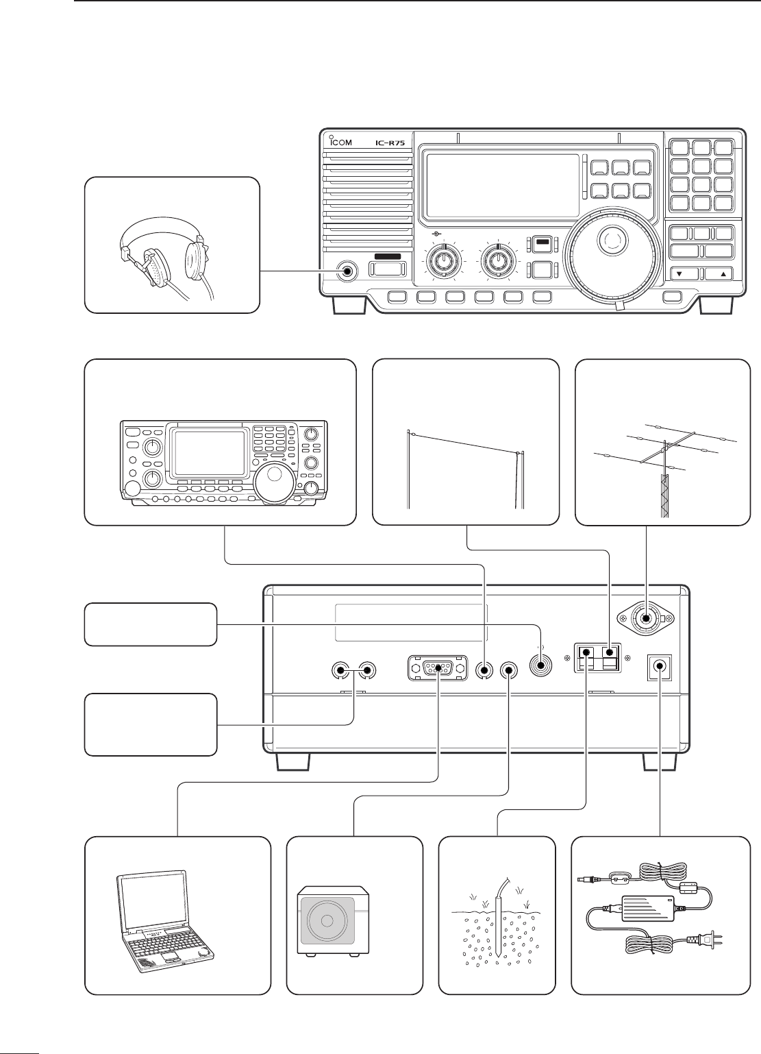
PC
AD-55/A/S/V*
or OPC-869
HEADPHONES
REMOTE (p. 9, 32)
Used for computer control and transceive.
ANTENNA 2
Connect a long wire
antenna; impedance: 500 Ω.
ANTENNA 1 (p. 9)
Connect a Yagi antenna;
impedance: 50 Ω.
EXTERNAL
SPEAKER (p. 39)
SP-21
GROUND (p. 7)RS-232C JACK (p. 10)
MUTE CONTROL
JACK (p. 6)
RECORDER/
RECORDER
CONTROL (p. 9)
DC13.8V JACK
*The AD-55, AD-55A, AD-55S
and AD-55V have different
shapes.
■ Connections
■ Tape recorder connections
■ Transceive function
9
3
INSTALLATION AND CONNECTIONS
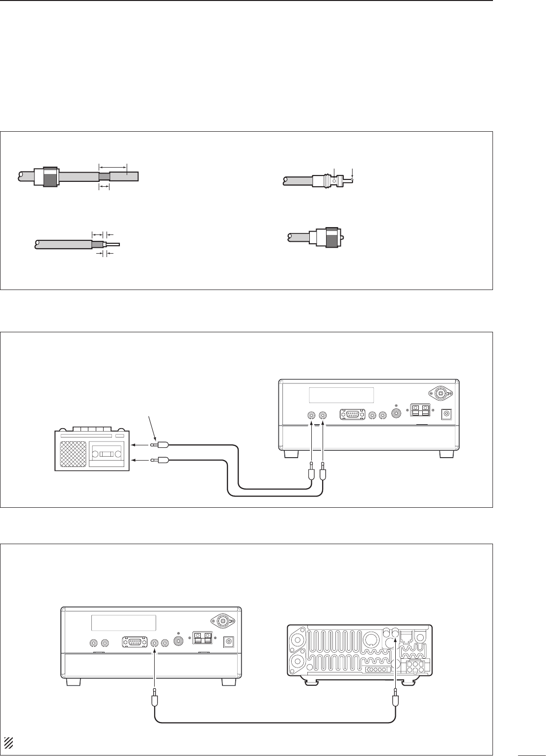
PL-259 CONNECTOR INSTALLATION EXAMPLE
30 mm
10 mm (soft solder)
10 mm
1–2 mm
solder solder
Soft
solder
Coupling ring
Slide the coupling ring
down. Strip the cable
jacket and soft solder.
Slide the connector
body on and solder it.
Screw the coupling ring
onto the connector
body.
Strip the cable as
shown at left. Soft
solder the center con-
ductor.
(10 mm ≈ 3⁄8 in)
q
w
e
r
■ Antenna connection
Antennas play a very important role in receiver
operation. Connecting a poor quality antenna to the
receiver will result in less than optimum performance.
When using a 50 Ω antenna, use [ANT 1] connector
for connection. When using a 500 Ω long wire
antenna, use [ANT 2] terminal for connection.
The [REC OUT] jack has 350 mV rms/4.7 kΩ output
for connection to other audio equipment.
[REC REMOTE] jack: Grounds when a signal is
received and squelch opens. If a tape recorder
has a control terminal, this jack can be used for
recording control. (1 A/DC max.)
[REC
REMOTE]
[REC OUT]
350 mVrms
4.7 kΩ
[AUX IN] or
[LINE IN] jack
IC-R75
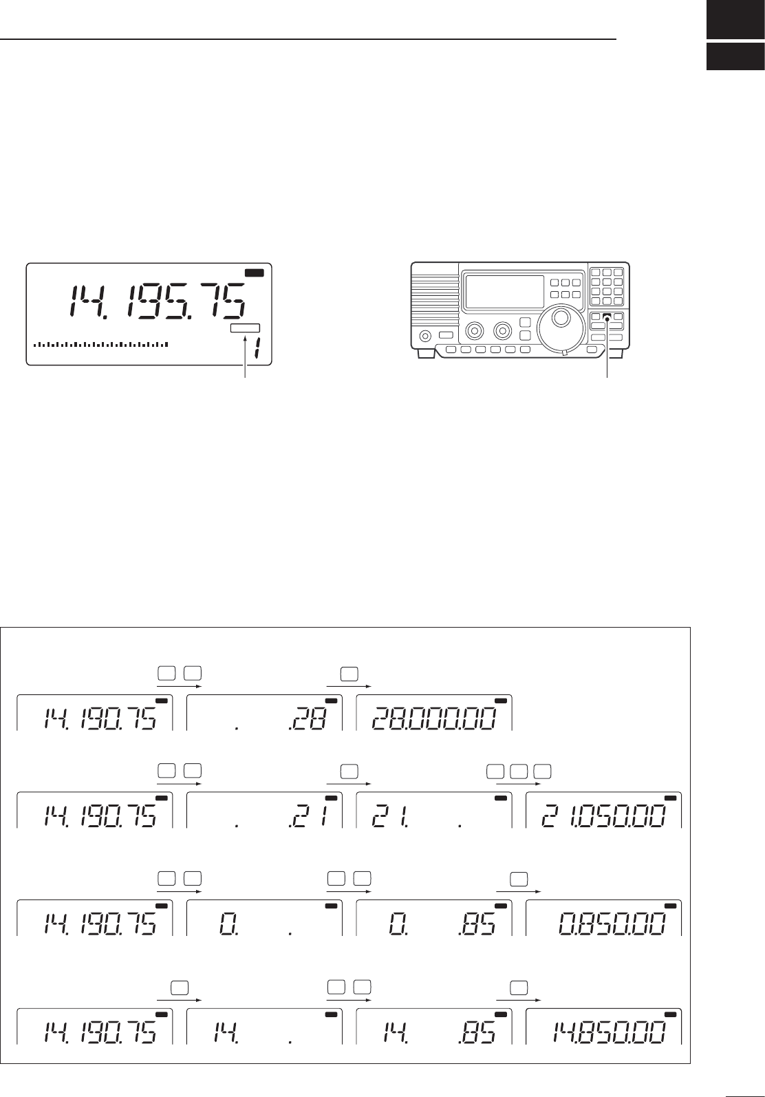
Icom CI-V transceivers or receivers can be connected
via the [REMOTE] jack. The frequency and mode
become the same* when either radio is changed.
* When a set frequency is out-of-range for one of the
connected transceivers or receivers, the connected
radio’s frequency/mode does not change.
[REMOTE]
IC-R75
Icom CI-V transceiver/receiver
Connect to [REMOTE] jack
Be sure the “CIV TRn” item is turned ON in set mode (p. 32).
10
3INSTALLATION AND CONNECTIONS
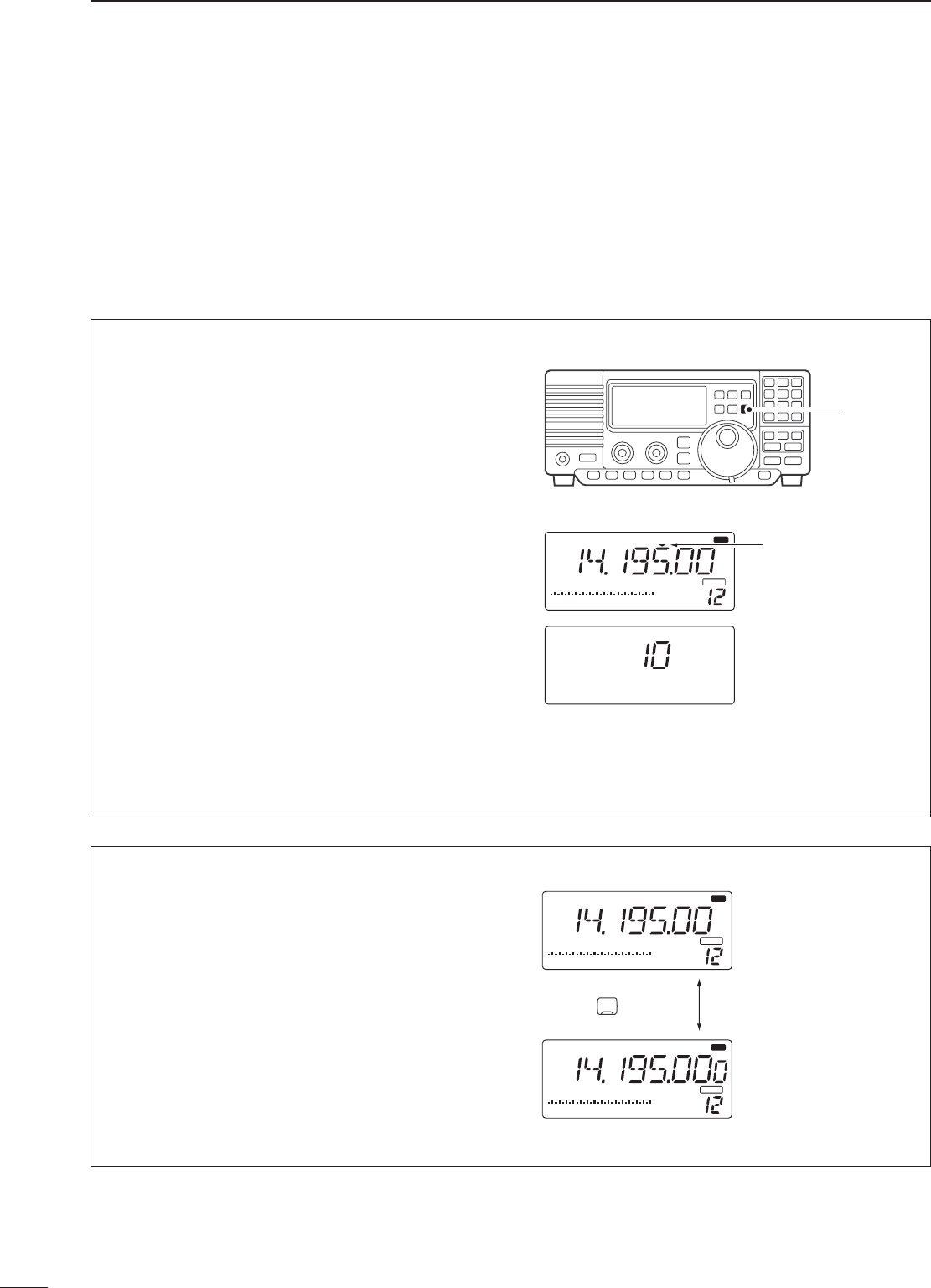
■ Connecting to a PC
To connect a terminal unit, TNC or scan converter,
refer to the diagram below.
q Connect a terminal unit as below.
w Select RTTY mode (or USB, CW modes for HF
band data communications).
e Set the receiver to the desired frequency as at
right.
r Set the connected terminal unit to the appropriate
settings.
• Refer to the terminal unit’s instructions.
The optional 250 Hz CW narrow filters may not
pass RTTY signals. Be sure to select the
appropriate IF filters corresponding to the signal
width. (pgs. 18, 19)
Frequency settings depend on the mode used.
FM mode:
[Setting frequency (displayed freq.)] = [Desired
freq.]
USB mode:
[Setting frequency (displayed freq.)] = [Desired
freq.] – [Center of Mark and Space freq.]
CW narrow mode:
[Setting frequency (displayed freq.)] = [Desired
freq.] – [Center of Mark and Space freq.] + [600 Hz]
LSB mode (for amateur RTTY):
[Setting frequency (displayed freq.)] = [Desired
freq.] + [Mark freq.]
The RS-R75 remote control software is available
to perform data setting and remote control of the
receiver.
Refer to the diagram below for connection.
D System requirements
To use this program, the following hardware and
software are required:
• IBM PC compatible computer
• An RS-232C serial port
•
Microsoft® Windows® 95 or Microsoft® Windows® 98
• Intel i486DX4 processor or faster (Pentium® 100
MHz or faster recommended)
• At least 16 MB RAM
• At least 10 MB of hard disk space
• At least 640 × 480 pixel, high color (16 bit) display
■ FSK and AFSK (SSTV) connections
TU or TNC
AF IN
SQUELCH IN
to [REC]to [REC
REMOTE]
2-conductor 3.5(d) plugs
PC
PC IC-R75
Supplied RS-232C cable (OPC-743)
4
11
FREQUENCY SETTING
■ Read me first
The receiver uses memory channels for storage of
frequencies (as well as mode, tuning steps, etc.). When
turning power OFF or changing memory channels,
the previously displayed frequency cannot be recalled
unless it has been stored into a memory channel.
Therefore, when you want to keep a displayed
frequency for later recall, you must program it into a
memory channel by pushing [MW] for 2 sec.
See p. 22 for details.
■ Using the keypad
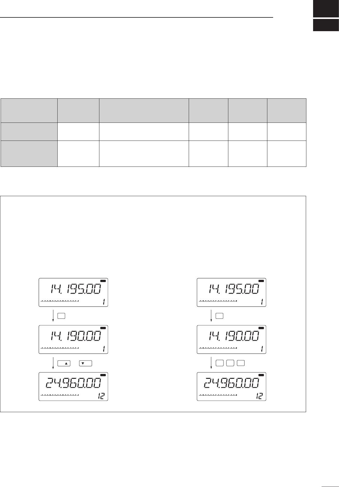
q Push the numeral keys on the keypad to enter the
MHz digits for the desired frequency.
• If a key is mistakenly pushed, push [CLR] and start
again from the beginning.
• When entering the same MHz digits as the displayed
frequency, this step can be skipped.
w Push [•] on the keypad.
e Push the numeral keys to enter the frequency
digits below 1 MHz.
• If a key is mistakenly pushed, push [CLR] and start
again from the beginning.
r Push [ENT] to set the input frequency.
• When pushing [ENT] after entering the MHz digits,
zeros are automatically entered for the kHz digits.
BLANKBLANK
S1 3 57920 40 60
dB
AGCANT
USB R X
VFO
1
“BLANK” appears above the memory channel
readout until [MW] is pushed for 2 sec.
Push [MW] for 2 sec. after tuning.
[EXAMPLE]: Setting the frequency using the keypad.
USB
R X
USB
USB
R X
USB
R X
USB
R X
USB
R X
USB
R X R X
USB
R X
USB
R X
USB
R X
USB
R X
USB
R X
USB
R X
USB
R X
USB
R X
1
5
JKL
8
TUV
.
.
.
0
QZ
5
JKL
8
TUV
USB
R X
0
QZ
•To set to 28.00 MHz
2
ABC
8
TUV
ENT
5
JKL
ENT
•To set to 21.050 MHz
2
ABC
•To set to 850 kHz (0.850 MHz)
ENT
ENT
•To change 14.19075 to 14.850 MHz
12
4FREQUENCY SETTING
■ Frequency setting
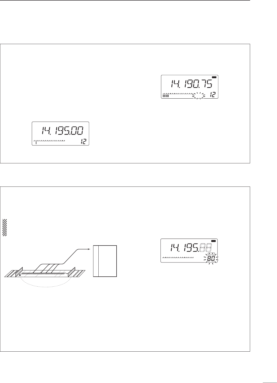
Rotate the tuning dial to change the frequency.
• The frequency changes in increments determined by the
selected tuning step (see below).
• When the lock function is activated (“LOCK” appears), the
frequency cannot be changed via tuning dial.
Push [TS] one or more times to select a quick tuning
step.
D Programmable tuning steps
Programmable tuning steps are available to suit your
operating requirements.
These tuning steps are:
• Independently selectable for each mode
• Selectable from 0.1, 1, 5, 6.25, 9, 10, 12.5, 20, 25,
100 kHz
q Select the desired operating mode with [SSB],
[CW/RTTY], [AM] or [FM]. (p. 14)
w Push [TS] one or more times until the
programmable tuning step indicator, “
√
,” appears
above the 1 kHz.
• Rotating the tuning dial changes the frequency
according to the set tuning step.
e Push [TS] for 2 sec. while the programmable
tuning step indicator appears to enter the tuning
step set mode.
r Rotate the tuning dial to set the desired tuning
step for the selected mode.
t Push [TS] to exit the tuning step set mode.
y Rotate the tuning dial to change the frequency
according to the set tuning step.
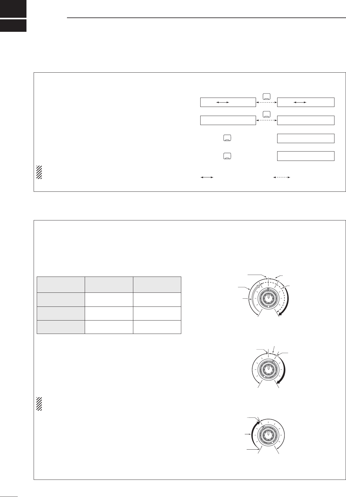
D 1 Hz and 10 Hz tuning steps
When both the 1 MHz tuning step and programmable
tuning step, “
√
,” disappear, rotating the tuning dial
changes the frequency in increments of 1 or 10 Hz.
q Push [TS] one or more times until the
programmable tuning step indicator or 1 MHz
tuning step indicator, “
√
,” disappears.
w Push [TS] for 2 sec. to toggle between the 1 and
10 Hz step settings.
• When the 1 Hz step is selected, the 1 Hz digit appears
in the frequency indication; when the 10 Hz step is
selected, the 1 Hz digit disappears from the frequency
indication.
USB R X
BLANKBLANK
S1 3 57920 40 60
dB
AGCANT
VFO
1
Programmable tuning
step indicator
10 kHz tuning step is
selected.
[TS]
USB
R X
BLANKBLANK
S1 3 57920 40 60
dB
AGCANT
VFO
1
USB
R X
BLANKBLANK
S1 3 57920 40 60
dB
AGCANT
VFO
1
Rotating the tuning dial
changes the frequency
in 10 Hz steps.
Rotating the tuning dial
changes the frequency
in 1 Hz steps.
TS
Push for 2 sec.
13
4
FREQUENCY SETTING
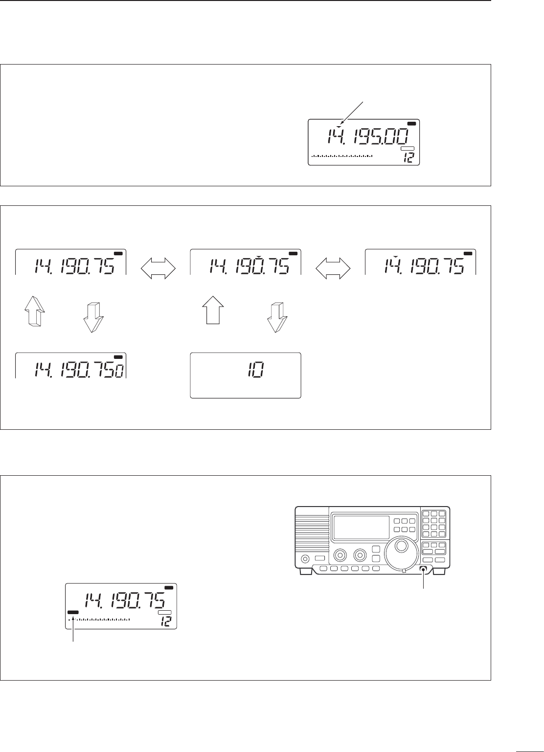
D 1 MHz quick tuning step
The quick tuning step function allows you to change
the frequency in 1 MHz steps when rotating the
tuning dial.
Push [TS] one or more times until the 1 MHz tuning
step indicator, “
√
,” appears above the 1 MHz
indicator.
USB
R X
BLANKBLANK
S1 3 57920 40 60
dB
AGCANT
VFO
1
Quick tuning step
indicator
10 Hz tuning
1 Hz tuning
momentarily
2 sec.2 sec.
2 sec.
1 MHz tuning
Programmable step tuning
(100 Hz –100 kHz)
Selectable for each mode.
momentarilymomentarily
USB
R X
USB
R X
USB
R X
USB
R X
[TS] SWITCH FLOW CHART
■ Dial lock function
The dial lock function prevents accidental changes
caused by the tuning dial. The lock function
electronically locks the dial.
Push [LOCK] momentarily to toggle the lock function
ON and OFF.
• “LOCK” appears in the function display while the lock
function is activated.
USB
R X
BLANKBLANK
S1 3 57920 40 60
dB
AGCANT
VFO
1
LOCK
“LOCK” appears while the lock
function is activated.
[LOCK]
5
14
RECEIVE FUNCTIONS
■ Mode selection
The following modes are available in the IC-R75:
SSB (LSB/USB), CW, CW REV (CW reverse), FM,
AM, RTTY and RTTY REV (RTTY reverse).
➥ Push [SSB] to toggle between LSB and USB.
➥ Push [CW/RTTY] momentarily to toggle between
CW and RTTY.
➥ Push [CW/RTTY] for 2 sec. to toggle between CW
and CW reverse or RTTY and RTTY reverse.
➥ Push [AM] to select AM.
➥ Push [FM] to select FM.
The selected mode is indicated in the function
display.
OPERATING MODE SELECTION
SSB
AM
Push momentarily
FM
Push momentarily
CW/RTTY
CW CW REV RTTY RTTY REV
Push mode switch
for 2 sec.
Push mode switch
momentarily.
AM
FM
LSB USB
■ Squelch and RF gain
The receiver uses the same control, [RF/SQL], to
adjust one of either the RF gain or the squelch.
[RF/SQL] adjusts either the RF gain or the squelch
depending on the operating mode selected and the
condition of the RF/SQL item in set mode (p. 30).
• [RF/SQL] control priority
* The RF gain is set to maximum level when the [RF/SQL]
is set as [SQL] control.
The RF (Radio Frequency) gain is used to adjust the
receiver gain.
• Shallow rotation moves the S-meter to the right indicating
the signal strength which can be received.
The recommended position for RF gain is the 12
o’clock position since this sets RF gain to the max.
The SQUELCH removes noise output from the
speaker (closed condition) when no signal is
received. The squelch is particularly effective for FM.
It is also available for the other modes.
• When operating in FM, first rotate the control fully
counterclockwise. Then, rotate the control clockwise to
the point where the noise just disappears. This is the best
position. The squelch does not open for weak signals
when it is set too deep.
• A segment appears in the S-meter to indicate the
S-meter squelch level.
• When set as the [RF/SQL] control
Set mode
setting
USB, LSB,
CW, RTTY AM, FM
Sq (SQL) SQL* SQL*
At (AUTO) RF GAIN SQL*
rS (RF/SQL) RF/SQL RF/SQL
Recommended level
Minimum RF gain
Adjustable range
RF gain adjustable
range
Maximum RF gain
Maximum RF gain
Squelch is open. S-meter squelch
S-meter squelch
threshold
Noise squelch threshold
(FM mode)
Shallow Deep
Squelch is open.
S-meter squelch
Noise squelch (FM mode)
Noise squelch (FM mode)
• When set as the [SQL] control
• When set as the [RF] control
15
5
RECEIVE FUNCTIONS
■ Twin PBT operation
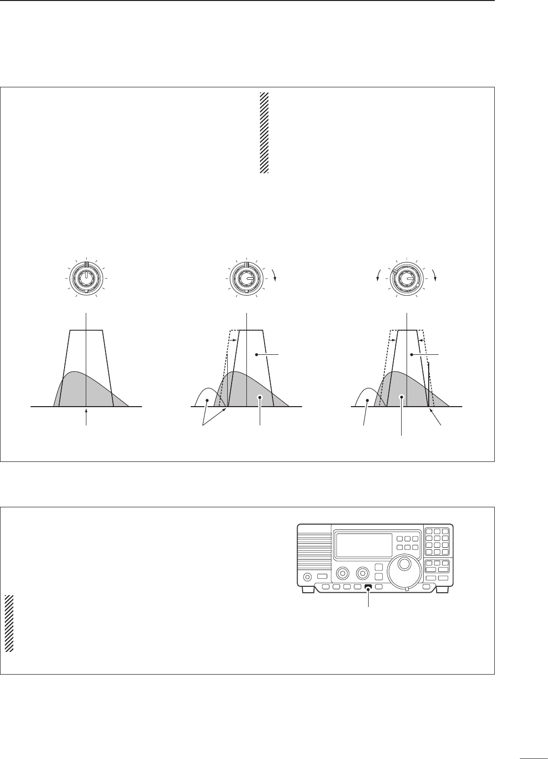
The twin PBT (Passband Tuning) function
electronically narrows the IF passband widths
to reduce interference. Moving both [TWIN PBT]
controls to the same position shifts the IF.
Variable range depends on the filter selection. ±1.29
kHz in 15 Hz steps and ±258 kHz in 3 Hz steps are
available.
PBT OPERATION EXAMPLE
• [TWIN PBT] should normally be set to the center
positions when there is no interference.
• When PBT is used, the audio tone may be
changed.
• PBT may not function with some IF filter
combinations.
• Not available for FM mode.
TWIN PBT TWIN PBTTWIN PBT
IF center frequency Interference Desired signal
Passband
Both controls at
center position
Cutting a lower
passband
Cutting both higher and
lower passbands
Interference Interference
Desired signal
Passband
■ Noise blanker
The noise blanker eliminates pulse-type noise
such as from car ignitions. The noise blanker is not
available for FM mode.
➥ Push the [NB] switch to turn the noise blanker ON
or OFF.
• When using the noise blanker, received signals
may be distorted if they are excessively strong.
• The noise blanker function in AM mode can be
deactivated depending on set mode setting. (p.
31)
[NB]
16
5RECEIVE FUNCTIONS
■ Preamp
The preamp amplifies received signals in the front
end circuit to improve the S/N ratio and sensitivity.
Turn this function ON when receiving weak signals.
➥ Push [P.AMP] to toggle between preamp-1 and
preamp-2 or turn the preamp OFF.
■ Attenuator
The attenuator prevents desired signals from
distorting when very strong signals are near the
desired frequency or when very strong electric fields,
such as from broadcasting stations, are near your
location.
➥ Push [ATT] toggle the 20 dB attenuator function
ON and OFF.
• “ATT” appears when the attenuator is turned ON.
■ AGC time constant
The AGC (Automatic Gain Control) controls receiver
gain to produce a constant audio output level even
when the received signal strength is varied by fading,
etc. Use AGC slow for normal phone operation; AGC
fast for receiving data and searching for signals.
➥ Push [AGC] momentary to toggle the AGC time
constant between fast and slow.
• “F.AGC” appears when the fast time constant is
selected.
• “AGC” appears when the slow time constant is
selected.
➥ Push [AGC] for 2 sec. to turn the AGC circuit OFF.
• “AGC OFF” appears when the AGC circuit is turned
OFF.
• Push [AGC] to turn the AGC circuit ON.
• S-meter is deactivated when the AGC circuit is turned
OFF.
USB R X
BLANKBLANK
S1 3 57920 40 60
dB
AGCANT
VFO
1PREAMP 1
“PREAMP” appears while the
preamp is activated.
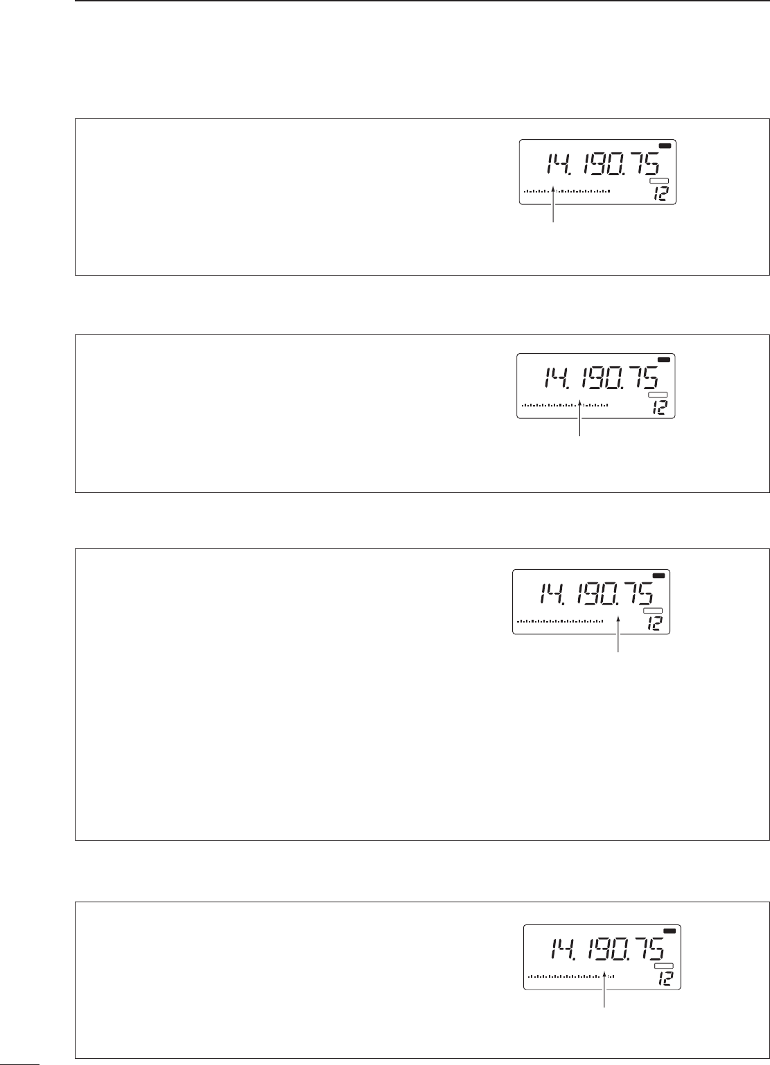
■ Antenna selection
2 types of antenna can be connected to this receiver.
When 2 antennas are connected, select an antenna
depending on the operating condition.
➥ Push [ANT(SET)] for 2 sec. to toggle between the
antenna 1 and 2 connectors.
• If a blank memory channel has been selected, push
[V/M] to select VFO mode in advance.
USB R X
BLANKBLANK
S1 3 57920 40 60
dB
AGCANT
VFO
1
“ANT1” appears when the
[ANT1] connector is in use.
USB
R X
BLANKBLANK
S1 3 57920 40 60
dB
AGCANT
VFO
1ATT
“ATT” appears while the attenuator
is activated.
USB
R X
BLANKBLANK
S1 3 57920 40 60
dB
AGCANT
VFO
1 F. AGC
“F.AGC” appears when the fast time
constant is selected.
17
5
RECEIVE FUNCTIONS
■ CW reverse mode
CW-R (CW Reverse) mode receives CW signals with
a reverse side CW carrier point like that of LSB and
USB modes.
Use when interfering signals are near a desired
signal and you want to change the interference tone.
q Push [CW/RTTY] once or twice to select CW
mode.
w Push [CW/RTTY] for 2 sec. to toggle between CW
and CW reverse (CW REV).
• Check the interfering tone.
• Receive audio tone response
■ RTTY reverse mode
Received characters are occasionally garbled when
the receive signal is reversed between MARK and
SPACE. This reversal can be caused by incorrect
TNC connections, settings, commands, etc.
To receive a reversed RTTY signal correctly, select
RTTY reverse mode.
q Push [CW/RTTY] once or twice to select RTTY
mode.
w Push [CW/RTTY] for 2 sec. to toggle between
RTTY and RTTY reverse (RTTY REV).
• Check the receive signal.
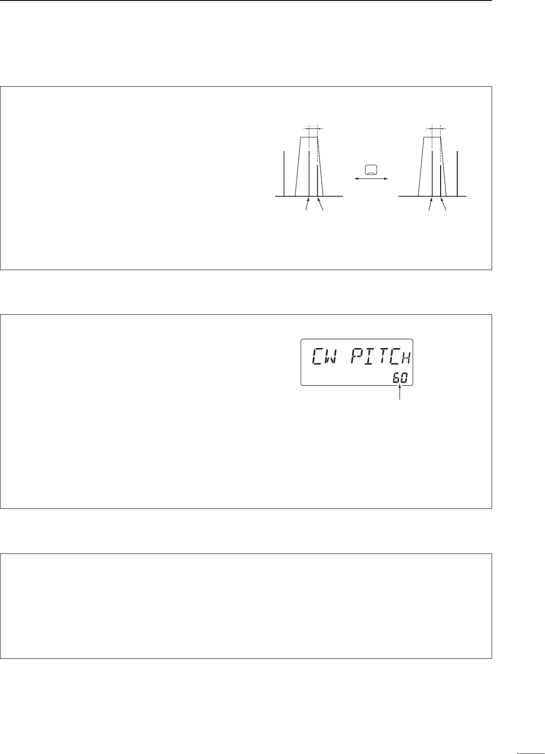
■ CW pitch control
The received CW audio pitch and monitored CW
audio can be adjusted to suit your preferences (300
to 900 Hz) without changing the operating frequency.
The received CW audio pitch can be adjusted in 10
Hz steps.
q Push [(ANT) SET] momentarily to enter set mode.
w Push [UP Y] or [Z DN] to select the ‘CW PITCH’
item.
e Rotate the tuning dial to set the desired CW audio
pitch.
• CW audio pitch is displayed in 10 Hz steps. ‘60’
indicates 600 Hz CW audio pitch.
r Push [(ANT) SET] again to exit set mode.
BFO
1/3 octave
Push for 2 sec.
Desired signal
(600 Hz)
CW mode (USB side)
Interference
(800 Hz)
BFO
1/2 octave
Desired signal
(600 Hz)
CW REV mode (LSB side)
Interference
(400 Hz)
CW/RTTY
Shows a 600 Hz CW audio pitch
18
5RECEIVE FUNCTIONS
■ Filter selection
The filter selection switches the IF passband width
as shown in the table at right.
The filter selection is automatically memorized in
each mode.
q Select the desired mode with the mode switches.
w Push [FIL] one or more times to select the desired
filter combination.
• ã or ç does not appear while in normal IF filter.
• ç appears when wide IF filters are selected.
• ã appears when narrow IF filters are selected.
When an optional filter is installed, set the optional
filter in filter set mode. Optional filters are not
selected by default.
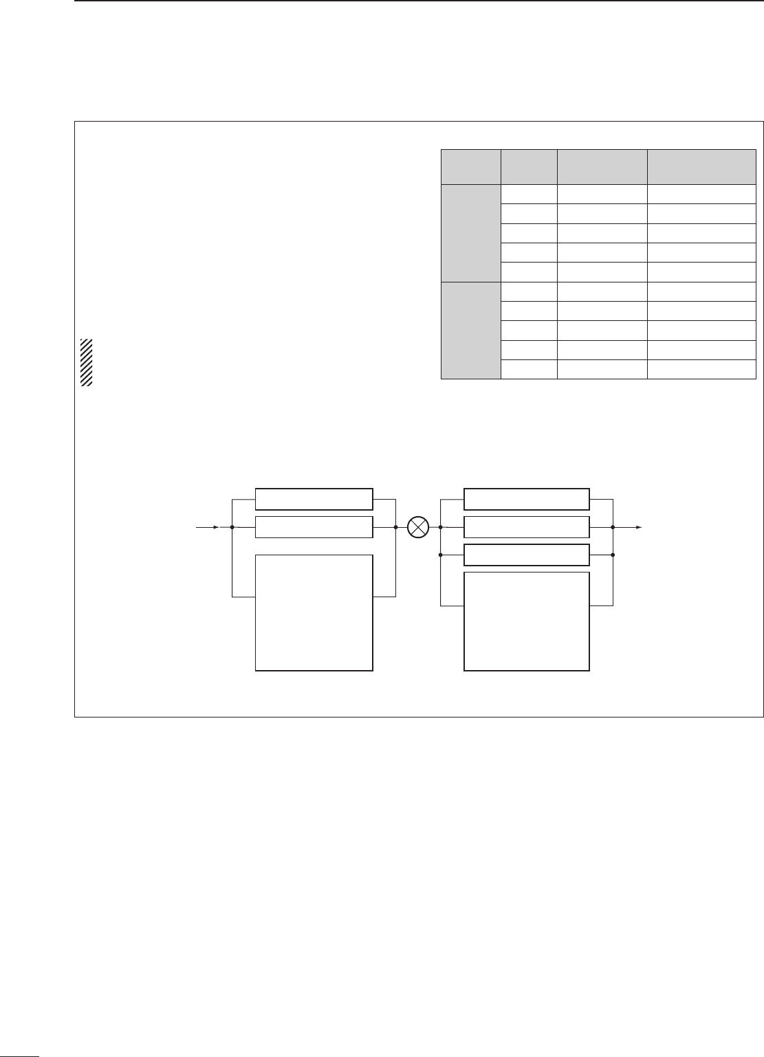
• Filter construction
CFWS450E (15 kHz)
CFWS450HT (6 kHz)
FL-65 (2.4 kHz)
FL-257 (3.3 kHz)
FL-96 (2.8 kHz)
FL-222 (1.8 kHz)
FL-52A (500 Hz)
FL-53A (250 Hz)
optional
FL-23 (15 kHz)
FL-272 (2.4 kHz)
FL-103 (2.8 kHz)
FL-223 (1.9 kHz)
FL-100 (500 Hz)
FL-232 (350 Hz)
FL-101 (250 Hz)
optional
Mixer
2nd IF signal 3rd IF signal
9 MHz IF filter 455 kHz IF filter
IF Filter Passband
width
Recommended
selectivity
9 MHz
FL-100 500 Hz/–6 dB CW-N, RTTY-N
FL-101 250 Hz/–6 dB
FL-103 2.8 kHz/–6 dB SSB-W
CW-N
FL-223 1.9 kHz/–6 dB SSB-N
455 kHz
FL-52A 500 Hz/–6 dB CW-N, RTTY-N
FL-53A 250 Hz/–6 dB CW-N
FL-96 2.8 kHz/–6 dB SSB-W
FL-232 350 Hz/–6 dB CW-N, RTTY-N
FL-222 1.8 kHz/–6 dB SSB-N
FL-257 3.3 kHz/–6 dB SSB-W
19
5
RECEIVE FUNCTIONS
■ Filter set mode
When an optional filter is installed, set the optional
filters in filter set mode. Optional filters are not
selected by default.
D Optional filter setting
q Push [FIL] for 2 sec. to enter filter set mode.
• If a blank memory channel has been selected, push
[V/M] to select VFO mode in advance.
w Push [UP Y] or [Z DN] one or more times until
“oP1” appears for 9 MHz IF filter setting or “oP2”
appears for 455 kHz IF filter setting.
e Rotate the tuning dial to select the installed filter.
• “No,” “100,” “101,” “103,” “223” and “232” indicate no
optional filter, FL-100, FL-101, FL-103, FL-223 and
FL-232, respectively for 9 MHz IF filter selection.
• “No,” “52A,” “53A,” “96,” “222” and “257” indicate no
optional filter, FL-52A, FL-53A, FL-96, FL-222 and
FL-257, respectively for 455 kHz IF filter selection.
r Push [FIL] to exit filter set mode.
D Wide/narrow filter setting
q Push [FIL] for 2 sec. to enter filter set mode.
• If a blank memory channel has been selected, push
[V/M] to select VFO mode in advance.
w Select the desired mode with the mode switches.
e Push [UP Y] or [Z DN] one or more times to
select the desired width 9 MHz or 455 kHz IF
filter.
• Wide or narrow mode can be deactivated when 9 MHz
wide or narrow filter is set to ‘OFF.’
• 455 kHz wide or narrow filter selection does appear
when 9 MHz wide or narrow filter is set to ‘OFF.’
r Rotate the tuning dial to select a filter.
t Repeat steps w and r to select IF filters for
other modes, if desired.
• The filter combinations are stored depending on
operating modes.
y Push [FIL] to exit filter set mode.
D Expanded filter selection ON/OFF
The selectable filter combinations can be expanded
by setting the expanded filter selection to ON.
q Push [FIL] for 2 sec. to enter filter set mode.
• If a blank memory channel has been selected, push
[V/M] to select VFO mode in advance.
w Push [UP Y] or [Z DN] one or more times until
“EXP” appears.
e Rotate the tuning dial to turn the expanded filter
selection ON/OFF.
• If ‘ON’ is selected, the expanded filter selection can be
used.
r Push [FIL] to exit filter set mode.
* 455 kHz wide or narrow filter selection does
appear when 9 MHz wide or narrow filter is set
to ‘OFF.’
USB
W
USB
W
USB
N
USB
USB
USB
N
USB
USB
USB
•9 MHz normal filter selection
•455 kHz normal filter selection
•9 MHz narrow filter selection
•455 kHz narrow filter selection*
•9 MHz wide filter selection
•455 kHz wide filter selection*
•Expanded filter selection ON/OFF
•9 MHz normal filter selection
•455 kHz normal filter selection
20
5RECEIVE FUNCTIONS
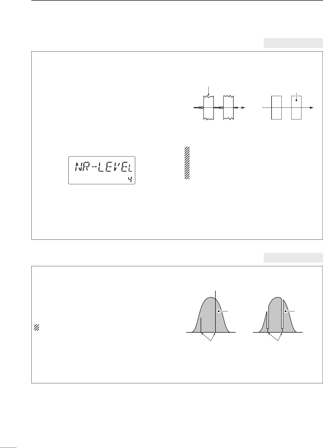
■ Optional auto notch function
When an optional UT-106 is installed (DSP appears
in the function display), an auto notch function can
be used.
The function automatically attenuates more than
3 beat tones, tuning signals, etc., even if they are
moving.
The auto notch functions in SSB mode only.
q Select SSB mode.
w Push [ANF] to turn the auto notch function ON.
• [ANF] indicator appears.
e Push [ANF] again to cancel the function.
• [ANF] indicator disappears.
Unwanted tone
frequency
Desired
signal (AF)
Desired
signal (AF)
Particular frequency
is attenuated
Auto notch OFF Auto notch ON
optional UT-106
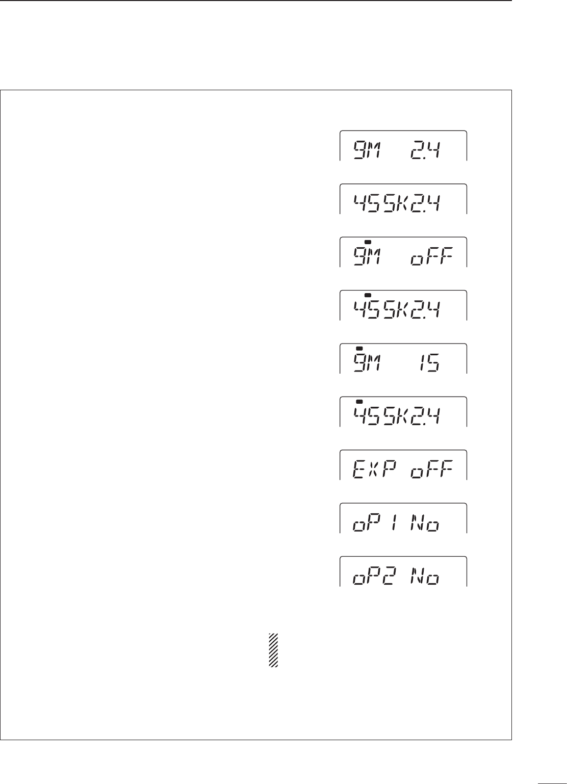
■ Optional noise reduction function
When an optional UT-106 is installed (DSP appears
in the function display), noise reduction function can
be used.
The noise reduction function reduces noise
components and picks out desired signals which
are buried in noise. The received AF signals are
converted to digital signals and then the desired
signals are separated from the noise.
q Push [NR] to turn the noise reduction ON.
• [NR] indicator appears.
w Push [NR] for 2 sec. to enter the noise reduction
level setting condition.
e Rotate the tuning dial to adjust the noise
reduction level.
r Push [NR] to exit the setting condition.
t Push [NR] again to turn the noise reduction OFF.
• [NR] indicator disappears.
• Noise reduction example
Higher setting of the [NR] level results in audio
signal masking or distortion. Set the [NR] level for
maximum clarity. The noise reduction function is
available in all modes, including AM and FM
modes.
Noise reduction OFF Noise reduction activated
Desired
signal (CW)
Noise components
optional UT-106
■ Memory channels
The receiver has 101 memory channels. The memory
mode is very useful for quickly changing to often-used
frequencies.
All 101 memory channels are tuneable which means
the programmed frequency can be tuned temporarily
with the tuning dial, etc. in memory mode.
■ Memory channel selection
6
21
MEMORY OPERATION
MEMORY
CHANNEL
MEMORY
CHANNEL
NUMBER
CAPABILITY TRANSFER
TO VFO
OVER-
WRITING CLEAR
Regular memory
channels 1–99 One frequency and one mode in
each memory channel. Yes Yes Yes
Scan edge
memory
channels
P1, P2
One frequency and one mode in
each memory channel as scan
edges for programmed scan.
Yes Yes No
D Using the [UP Y] or [Z DN] keys
q Push [V/M] to select memory mode.
• “MEMO” appears.
w Push [UP Y] or [Z DN] several times to select the
desired memory channel.
• Push and hold [UP Y] or [Z DN] for continuous
selection.
e To return to VFO mode, push [V/M] again.
D Using the keypad
q Push [V/M] to select memory mode.
• “MEMO” appears.
w Push the desired memory channel number using
the keypad.
• Enter 100 or 101 to select scan edge channel P1 or
P2, respectively.
e Push [V/M] to select the desired memory channel.
r To return to VFO mode, push [V/M] again.
USB
R X
S1 3 57920 40 60
dB
AGCANT
MEMO
1
USB
R X
S1 3 57920 40 60
dB
AGCANT
MEMO
1
USB
R X
S1 3 57920 40 60
dB
AGCANT
VFO
1
UP DN
or
V/M
USB
R X
S1 3 57920 40 60
dB
AGCANT
MEMO
1
USB
R X
S1 3 57920 40 60
dB
AGCANT
MEMO
1
USB
R X
S1 3 57920 40 60
dB
AGCANT
VFO
1
1 2
ABC
V/M
V/M
Memory channel programming can be preformed
either in VFO mode or in memory mode.
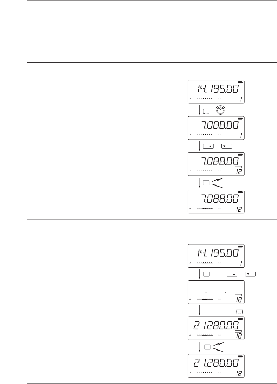
■ Memory channel programming
22
6MEMORY OPERATION
D Programming in memory mode
q Select the desired memory channel with [UP Y]
or [Z DN] in memory mode.
• “BLANK” appears if the selected memory channel is a
blank channel (and does not have contents).
w Set the desired frequency and operating mode in
memory mode.
• To program a blank channel, use direct frequency
entry with the keypad in advance.
e Push [MW] for 2 sec. to program the displayed
frequency and operating mode into the memory
channel.
• Preamp setting, attenuator on/off, antenna selection,
and AGC setting can also be programmed into a
memory channel.
[EXAMPLE]: Programming 21.280 MHz/CW into
memory channel 18.
D Programming in VFO mode
q Set the desired frequency and operating mode in
VFO mode.
w Push [UP Y] or [Z DN] several times to select the
desired memory channel.
• “BLANK” appears if the selected memory channel is a
blank channel (and does not have contents).
e Push [MW] for 2 sec. to program the displayed
frequency and operating mode into the memory
channel.
• Preamp setting, attenuator on/off, antenna selection,
and AGC setting can also be programmed into a
memory channel.
[EXAMPLE]: Programming 7.088 MHz/LSB into
memory channel 12.
R X
S1 3 57920 40 60
dB
AGCANT 1
USB
R X
S1 3 57920 40 60
dB
AGCANT
VFO
VFO
1
MW
LSB
R X
S1 3 57920 40 60
dB
AGCANT 1
VFO
LSB
BLANKBLANK
R X
S1 3 57920 40 60
dB
AGCANT 1
VFO
LSB
UP DN
or
Push for 2 sec.
or keypad
Beep
Beep
Beep
SSB
S1 3 57920 40 60
dB
USB
R X
S1 3 57920 40 60
dB
AGCANT
VFO
1
MW
R X
S1 3 57920 40 60
dB
AGCANT 1
BLANKBLANK
V/M
BLANKBLANK
MEMO
CW/RTTY
R X
CW
R X
S1 3 57920 40 60
dB
AGCANT 1
R X
CW
MEMO
MEMO
UP DN
orthen
then
Push for 2 sec.
keypad
Beep
Beep
Beep
■ Frequency transferring
The frequency and operating mode in a memory
channel can be transferred to the VFO.
Frequency transferring can be performed in either
VFO mode or memory mode.
23
6
MEMORY OPERATION
D Transferring in memory mode
This is useful for transferring frequency and
operating mode while operating in memory mode.
When you have changed the frequency or
operating mode in the selected memory channel:
• Displayed frequency and mode are transferred.
• Programmed frequency and mode in the
memory channel are not transferred, and they
remain in the memory channel.
q Select the memory channel to be transferred with
[UP Y] or [Z DN] in memory mode.
• And, set the frequency or operating mode if required.
w Push [V/M] for 2 sec. to transfer the frequency
and operating mode.
• Displayed frequency and operating mode are
transferred to the VFO.
e To return to VFO mode, push [V/M] momentarily.
TRANSFERRING EXAMPLE IN MEMORY MODE
Operating frequency : 14.020 MHz/CW (M-ch 16)
Contents of M-ch 16 : 14.018 MHz/CW
D Transferring in VFO mode
This is useful for transferring programmed contents
to VFO.
q Select VFO mode with [V/M].
w Select the memory channel to be transferred with
[UP Y] or [Z DN].
• “BLANK” appears if the selected memory channel is a
blank channel (and does not have contents).
e Push [V/M] for 2 sec. to transfer the frequency
and operating mode.
• Transferred frequency and operating mode appear on
the frequency readout.
TRANSFERRING EXAMPLE IN VFO MODE
Operating frequency : 21.320 MHz/USB (VFO)
Contents of M-ch 16 : 14.018 MHz/CW
S1 3 57920 40 60
dB
AGCANT 1
VFO
V/M
R X
S1 3 57920 40 60
dB
AGCANT
VFO
1
CW
S1 3 57920 40 60
dB
AGCANT
VFO
1
USB R X
USB R X
UP DN
or
Push for 2 sec.
Beep
Beep
Beep
S1 3 57920 40 60
dB
AGCANT 1
V/M
R X
S1 3 57920 40 60
dB
AGCANT
VFO
1
CW
S1 3 57920 40 60
dB
AGCANT 1
R X
R X
V/M
CW
CW
MEMO
MEMO
V/M
S1 3 57920 40 60
dB
AGCANT 1
R X
CW
MEMO
Push for 2 sec.
Displayed memory
channel contents
are transferred.
Memory channel
contents remain in
the memory channel.
Beep
Beep
Beep
■ Memory clearing
■ Memory names
24
6MEMORY OPERATION
All memory channels (including scan edges) can be
tagged with alphanumeric names of up to 8 characters
each.
Letters (capitals except ‘o’), numerals and spaces can
be used. Numerals can only be used for the 7th and
8th digits.
D Turning memory name indication ON/
OFF
q Select memory mode with [V/M].
w Push [SEL] for 2 sec. to turn memory name
indication ON.
• Frequency disappears and a memory name appears
if programmed.
e Push [SEL] for 2 sec. to turn memory name
indication OFF.
While the memory name indication is selected,
pushing [TS] shows the operating frequency; and
rotating the tuning dial while pushing [TS]
changes the frequency temporally.
D Editing (programming) memory names
q Select memory mode with [V/M].
w Push [SEL] for 2 sec. to turn memory name
indication ON.
e Select the memory channel to program with [UP
Y] or [Z DN].
• “BLANK” appears if the selected memory channel is a
blank channel (and does not have contents).
r Push [ENT] to edit memory channel name.
• A cursor appears and blinks.
• Memory channel names of blank channels cannot be
edited.
t Input the desired character by pushing a key on
the keypad one or more times.
• [1] inputs numeral 1.
• [2] inputs numeral 2 and letters A to C.
• [3] inputs numeral 3 and letters D to F.
• [4] inputs numeral 4 and letters G to I.
• [5] inputs numeral 5 and letters J to L.
• [6] inputs numeral 6 and letters M to O.
• [7] inputs numeral 7 and letters P, R and S.
• [8] inputs numeral 8 and letters T to V.
• [9] inputs numeral 9 and letters W to Y.
• [0] inputs numeral 0 and letters Q and Z.
• Rotate tuning dial for cursor movement.
• Numerals can only be used for the 7th and 8th digits.
• Push [•] to delete the selected character and input a
space.
y Push [ENT] to input the set the name.
• The cursor disappears.
• Push [CLR] to abandon the settings and return to
previous memory name.
u Repeat steps e to y to program another
memory channel’s name, if desired.
i Push [SEL] for 2 sec. to turn memory name
indication OFF.
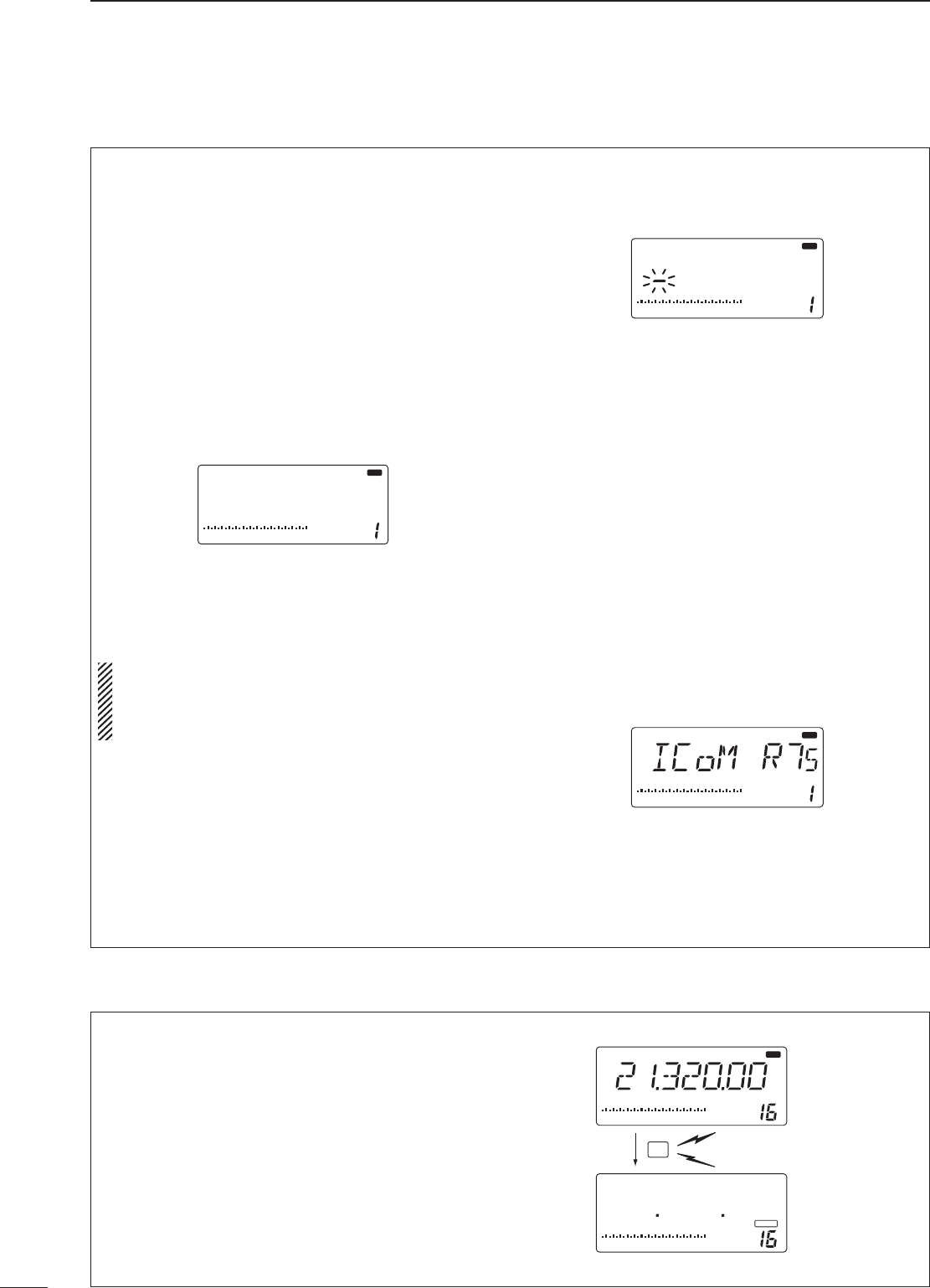
Any unnecessary memory channels can be cleared.
The cleared memory channels become blank
channels.
q Select memory mode with [V/M].
w Select the memory channel to be cleared with
[UP Y] or [Z DN].
e Push [CLR] for 2 sec. to clear the contents.
• The programmed frequency and operating mode
disappear.
• “BLANK” appears.
r To clear other memory channels, repeat steps w
and e.
S1 3 57920 40 60
dB
S1 3 57920 40 60
dB
AGCANT 1
USB
R X
CLR
BLANKBLANK
MEMO
MEMO
Push for 2 sec.
Beep
Beep
Beep
S1 3 57920 40 60
dB
AGCANT 1
USB R X
MEMO
Non-named channel
S1 3 57920 40 60
dB
AGCANT 1
USB
R X
MEMO
S1 3 57920 40 60
dB
AGCANT 1
USB
R X
MEMO
■ Scan types
7
25
SCANS
■Preparation
• Channels
For programmed scan/auto memory write scan:
Program scan edge frequencies into scan edge
memory channels P1 and P2.
For memory scan:
Program 2 or more memory channels except scan
edge memory channels.
For select memory scan:
Designate 2 or more memory channels as select
memory channels. To designate the channel as a
select memory channel, select a memory channel,
then push [SEL] in the scan screen (memory mode)
or in the memory channel screen.
For priority watch:
Program 1 or more memory channels.
• Scan resume ON/OFF
You can select the scan to resume or cancel when
detecting a signal, in set mode. Scan resume ON/OFF
must be set before operating a scan. See p. 31 for ON/
OFF setting and scan resume condition details.
• Scan speed
Scan speed can be selected from 2 levels, high or
low, in set mode. See p. 31 for details.
• Squelch condition
❍ Scan starts with squelch open
For programmed scan:
When tuning step is 1 kHz or less:
The scan continues until it is stopped manually— it
does not pause* even if signals are detected.
* The scan is paused when the squelch is closed and
then opened (scan resumes after 10 sec. has passed
when the scan resume is ON; scan is cancelled when
the scan resume is OFF).
When tuning step is more than 5 kHz:
The scan pauses on each step when the scan
resume is ON; not applicable when the scan
resume is OFF.
For memory scan:
Scan pauses on each channel when the scan resume
is ON; not applicable when the scan resume is OFF.
❍ Scan starts with squelch closed
Scan stops when a signal is detected.
• If the scan resume is set to ON in scan set mode, the scan
pauses for 10 sec. when detecting a signal, then resumes.
When a signal disappears while scan is paused, scan
resumes 2 sec. later.
PROGRAMMED SCAN/AUTO MEMORY WRITE SCAN
Repeatedly scans between two scan edge frequencies
(scan edge memory channels P1 and P2). Auto memory
write scan automatically memorizes paused frequencies
into memory channels 80 to 99.
This scan operates in VFO mode.
PRIORITY WATCH
Repeatedly watches a memory channel.
This scan operates in memory mode. This scan operates in VFO mode.
Scan
Scan edge
P1 or P2
Scan edge
P2 or P1
Jump
This scan operates in memory mode.
MEMORY SCAN
Repeatedly scans all programmed memory channels.
Mch 1 Mch 5
Mch 2 Mch 3 Mch 4
Mch 6Mch 7Mch 99
BLANK
S (select)
S (select) S (select)
S (select)
S (select)
SELECT MEMORY SCAN
Repeatedly scans all select memory channels.
Mch 1 Mch 5
Mch 2 Mch 3 Mch 4
Mch 6Mch 7Mch 99
BLANK
S (select)
S (select) S (select)
S (select)
S (select) VFO
frequency
Memory
channel
5 sec.
125 msec.
26
7SCANS
■ Programmed scan operation
q Select VFO mode with [V/M].
w Select the desired operating mode.
• The operating mode can also be changed while
scanning.
e Set [RF/SQL] open or closed.
• See previous page for scan condition.
• If the [RF/SQL] control function is set as RF control,
the squelch always opens. See pgs. 14, 30 for details.
r Push [SCAN] to start the programmed scan.
• “SCAN” appears while scanning.
t When the scan detects a signal, the scan stops,
pauses or ignores it depending on the resume
setting and the squelch condition.
y To cancel the scan, push [SCAN].
If the same frequencies are programmed into the
scan edge memory channel P1 and P2,
programmed scan does not start.
USB
R X
S1 3 57920 40 60
dB
AGCANT 1
SCAN
VFO
■ Memory/select memory scan operation
q Select memory mode with [V/M].
w Select the desired operating mode.
• The operating mode can also be changed while
scanning.
e Set [RF/SQL] open or closed.
• See previous page for scan condition.
• If the [RF/SQL] control function is set as RF control,
the squelch always opens. See pgs. 14, 30 for details.
r Push [SCAN] to start the memory/select memory
scan.
• “SCAN” appears while scanning.
t Push [SEL] to toggle between memory scan and
select memory scan.
y When the scan detects a signal, the scan stops,
pauses or ignores it depending on the resume
setting and the squelch condition.
u To cancel the scan, push [SCAN].
2 or more memory channels must be programmed
for memory scan to start.
USB
R X
S1 3 57920 40 60
dB
AGCANT
MEMO
1
SCAN
S
■ Setting select memory channels
q Select memory mode with [V/M].
w Select the desired memory channel to set as
select memory channel.
e Push [SEL] to set the memory channel as a select
memory or not.
• “S” appears for select memory channels.
r Repeat steps w to e to program another
memory channel as a select memory channel, if
desired.
USB R X
S1 3 57920 40 60
dB
AGCANT
MEMO
1
S
“S” appears for the select channel.
27
7
SCANS
■ Priority watch operation
Priority watch checks for signals on a frequency
every 5 sec. while operating on a VFO frequency.
q Select memory mode with [V/M].
w Select the desired memory channel to be
watched with [UP Y] or [Z DN].
e Select VFO mode.
r Set [RF/SQL] closed.
• If the [RF/SQL] control function is set as RF control,
the squelch always opens. See pgs. 14, 30 for details.
t Push [SCAN] for 2 sec. to start priority watch.
• “SCAN” appears.
y When a signal is received on a watch channel,
the function display shows the watch channel and
“SCAN” blinks.
u To cancel the watch, push [SCAN].
USB
S1 3 57920 40 60
dB
AGCANT 1
SCAN
VFO
USB
S1 3 57920 40 60
dB
AGCANT 1
SCAN
R X
MEMO
■ Auto memory write scan
Auto memory write scan operates in the same way
as programmed scan. However, when a signal is
received, the received frequency is automatically
written into memory channels (80 to 99).
When the auto memory write scan starts, the
previously written memory channels (80 to 99) are
cleared.
q Select VFO mode with [V/M].
w Select the desired operating mode.
• The operating mode can also be changed while
scanning.
e Set [RF/SQL] closed.
• If the [RF/SQL] control function is set as RF control,
the squelch always opens. See pgs. 14, 30 for details.
r Push [SCAN] to start the programmed scan.
• “SCAN” appears while scanning.
• If the same frequencies are programmed into the scan
edge memory channel P1 and P2, programmed scan
does not start.
t Push [MW] to start the auto memory write scan.
• “80” blinks when auto memory write scan starts.
y When the scan detects a signal, the frequency is
programmed into a memory channel (80 to 99),
starting from channel 80.
u To cancel the scan, push [SCAN].
80
81
82
83
84
•
•
•
98
99
14.456.00
14.567.00
14.678.00
14.890.00
14.050.00
--------------
--------------
USB R X
S1 3 57920 40 60
dB
AGCANT 1
SCAN
VFO
BLANKBLANK
■ Setting the current time
The receiver has a built-in 24-hour clock with power-
off and power-on timer functions. This is useful when
logging SWL’s, BCL’s and so on.
q Push [CLOCK] to select clock indication mode.
• Current time and “CL” appear.
w Push [(ANT) SET] for 2 sec. to enter time setting
condition.
• Current time flashes.
e Set the current time using the tuning dial; or push
keypad using 4-digit 24 hour system.
r Push [ENT] to set the time.
• Push [CLR] to cancel the setting.
t Push [CLOCK] to exit clock indication mode.
8
28
CLOCK AND TIMERS
■ Setting power-on time
The receiver can be set to turn ON automatically at
a specified time.
q Push [CLOCK] to select clock indication mode.
w Push [UP Y] to select power-on timer screen.
• Power-on time and “on” appear.
e Push [(ANT) SET] for 2 sec. to enter time setting
condition.
• Power-on time flashes.
• Push [(ANT) SET] momentarily when the power-on
timer is already turned ON.
r Set the desired time using the tuning dial; or push
keypad using 4-digit 24 hour system.
t Push [ENT] to set the time.
• Power-on timer is automatically turned ON.
• Push [CLR] to cancel the setting.
y Push [(ANT) SET] momentarily to toggle the
power-on timer ON and OFF, if necessary.
• “o” and “X” indicates the power-on timer is turned ON
and OFF, respectively.
u Push [ENT] to exit clock indication mode.
i Push [POWER] for 2 sec. to turn the power OFF.
• When the set time arrives, the power is automatically
turned ON.
TIMER
29
8
CLOCK AND TIMERS
■ Setting power-off time
The receiver can be set to turn OFF automatically at
a specified time.
q Push [CLOCK] to select clock indication mode.
w Push [UP Y] or [Z DN] twice to select power-off
timer screen.
• Power-off time and “oF” appear.
e Push [(ANT) SET] for 2 sec. to enter time setting
condition.
• Power-off time flashes.
• Push [(ANT) SET] momentarily when the power-off
timer is already turned ON.
r Set the desired time using the tuning dial; or push
keypad using 4-digit 24 hour system.
t Push [ENT] to set the time.
• Power-off timer is automatically turned ON.
• Push [CLR] to cancel the setting.
y Push [(ANT) SET] momentarily to toggle the
power-off timer ON and OFF, if necessary.
• “o” and “X” indicates the power-off timer is turned ON
and OFF, respectively.
u Push [ENT] to exit clock indication mode.
• When the set time arrives, the power is automatically
turned OFF with 5 beeps.
TIMER
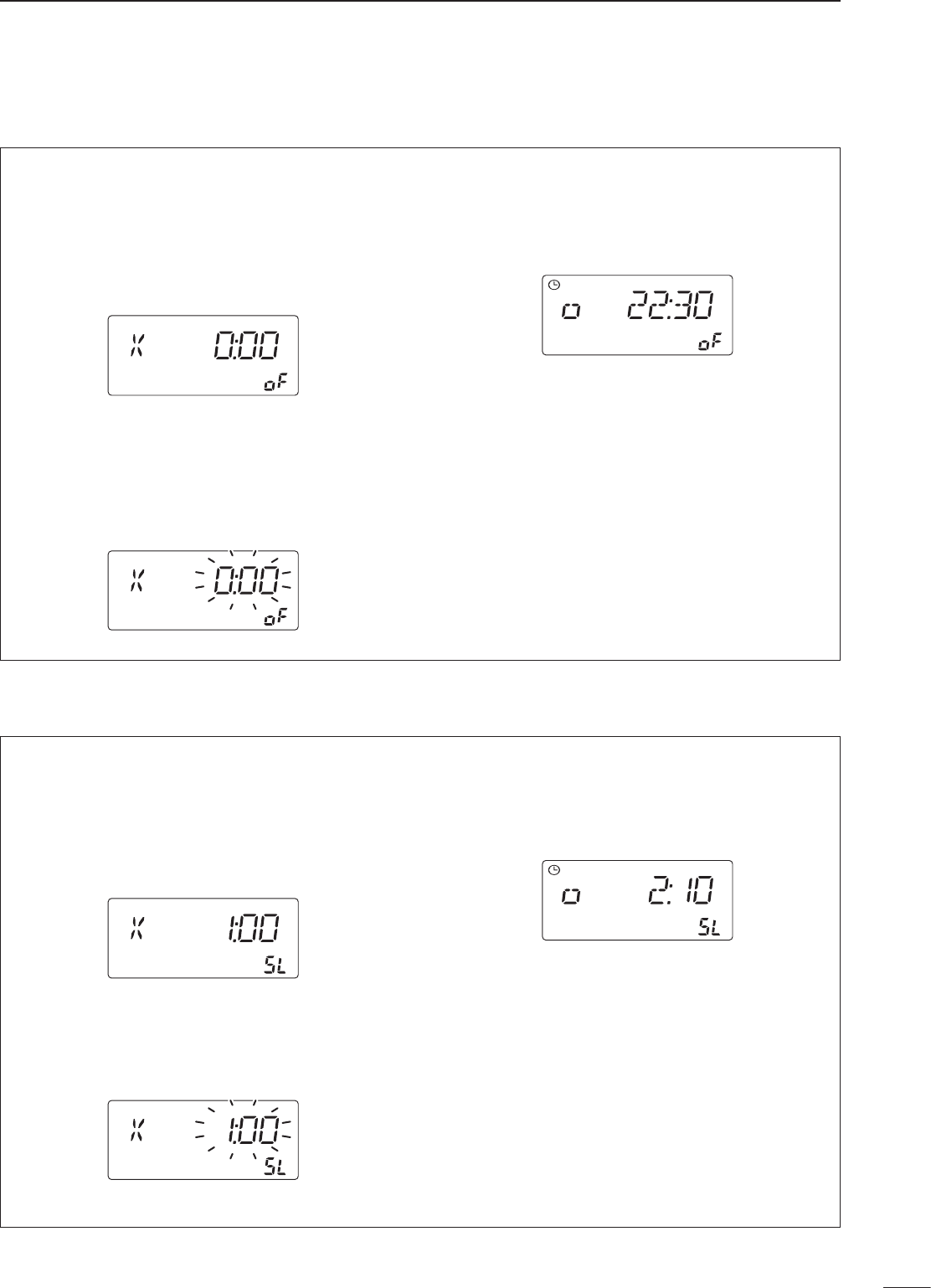
■ Setting sleep timer period
The receiver can be set to turn OFF automatically.
The power-off period can be set from 1 min. to 23
hours 59 min.
q Push [CLOCK] to select clock indication mode.
w Push [Z DN] to select sleep timer screen.
• Sleep timer period and “SL” appear.
e Push [(ANT) SET] for 2 sec. to enter time setting
condition.
• Sleep timer period flashes.
r Set the desired periods using the tuning dial; or
push keypad using 4-digit 24 hour system.
t Push [ENT] to set the periods.
• Sleep timer is automatically turned ON.
• Push [CLR] to cancel the setting.
y Push [(ANT) SET] momentarily to toggle the sleep
timer ON or OFF, if necessary.
• “o” and “X” indicates the sleep timer is turned ON and
OFF, respectively.
u Push [ENT] to exit clock indication mode.
i The receiver emits 5 beeps and turns OFF after
the sleep timer period elapses.
TIMER
9
30
SET MODE
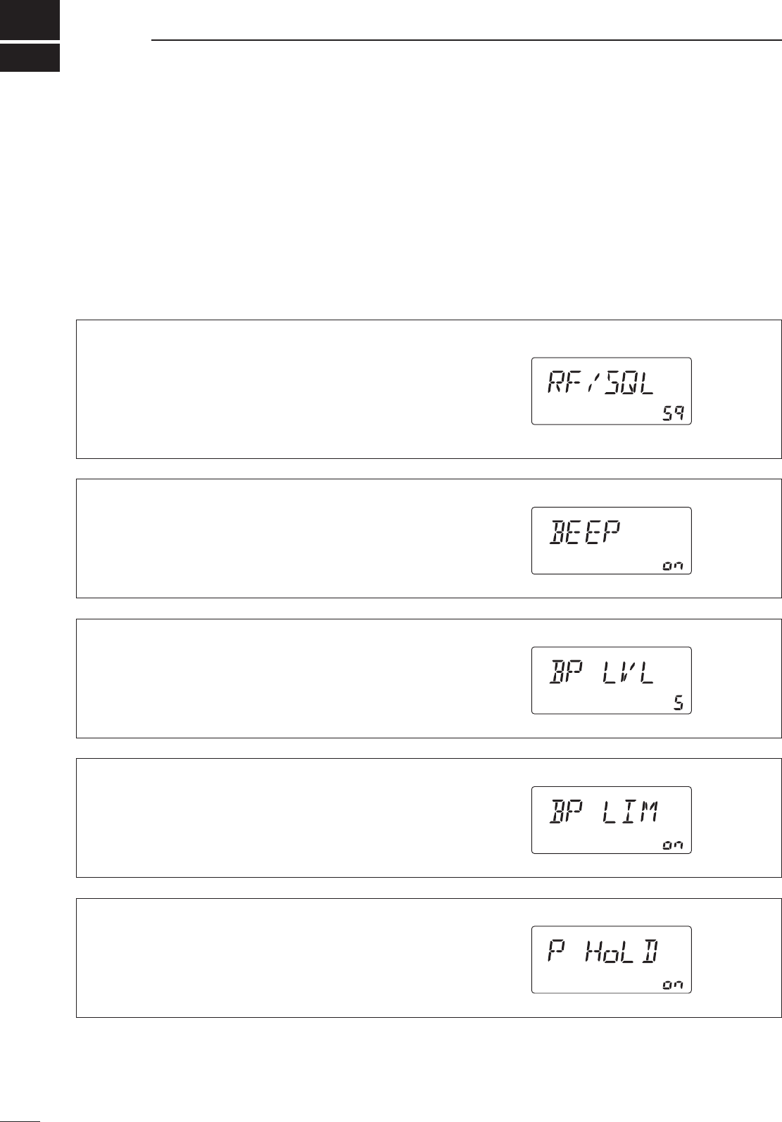
■ Set mode description
Set mode is used for programming infrequently
changed values or conditions of functions.
D Set mode operation
q Push [(ANT) SET] to enter the set mode.
w Push [UP Y] or [Z DN] to select the desired item.
e Set the desired condition using the tuning dial.
r Push [(ANT) SET] to exit the set mode.
• RF/squelch control
The [RF/SQL] control can be set as the squelch
control (default; RF gain is fixed at maximum), the
RF gain control only (squelch is fixed as open) or
RF/squelch control.
See p. 14 for details.
• Confirmation beep
A beep sounds each time a switch is pushed to
confirm it. This function can be turned OFF for silent
operation.
The volume level can be set in the next item.
• Beep level
This item adjusts the volume level for confirmation
beep tones from 0% to 100% in 1% steps.
• The volume level is displayed in 10% steps. ‘5’ indicates
50% volume level.
• S-meter peak hold
The peak level of the S-meter can be displayed for
0.5 sec. to confirm it easily.
• Beep level limit
This item limits the maximum volume level for
confirmation beep tones.
31
9
SET MODE
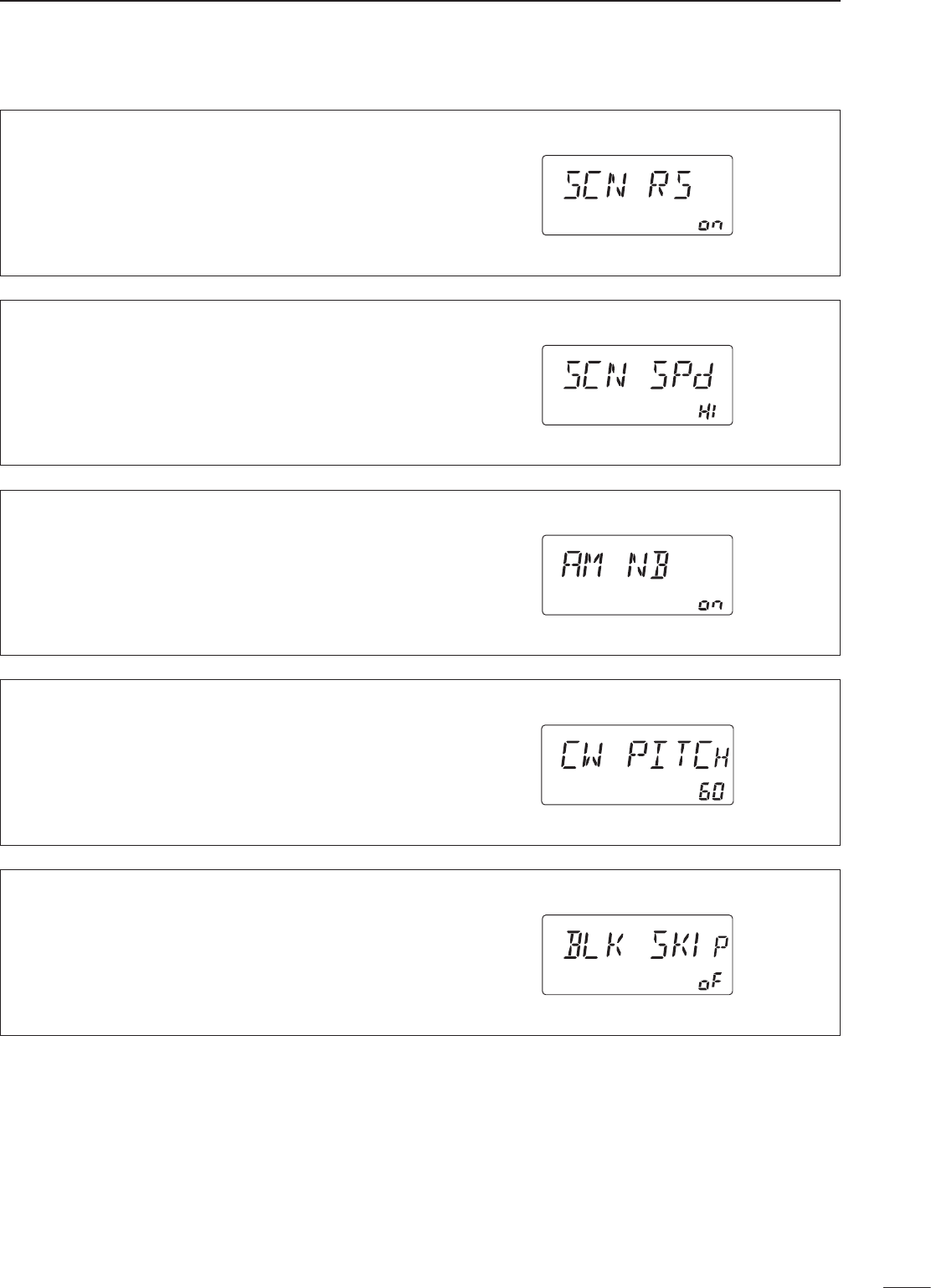
• Scan resume
This item sets the scan resume function ON or OFF.
• “on” scan resumes 10 sec. after stopping on a signal (or
2 sec. after a signal disappears)
• “oF” scan does not resume after stopping on a signal.
See p. 25 for scanning details.
• Scan speed
The receiver has 2 speeds for scanning, high and
low.
See p. 25 for scanning details.
• AM mode noise blanker
The noise blanker for AM mode can be turned ON
and OFF.
• CW pitch control
The received CW audio pitch and monitored CW
audio can be adjusted to suit your preferences (300
to 900 Hz) without changing the operating frequency.
• The CW audio pitch can be adjusted in 10 Hz steps.
• The CW audio pitch is displayed in 10 Hz steps. ‘60’
indicates 600 Hz CW audio pitch.
• Blank channel indication
This item sets the blank channel indication ON or
OFF.
• “on” blank memory channels are skipped and can not
be selected.
• “oF” all memory channels can be selected.
32
9SET MODE
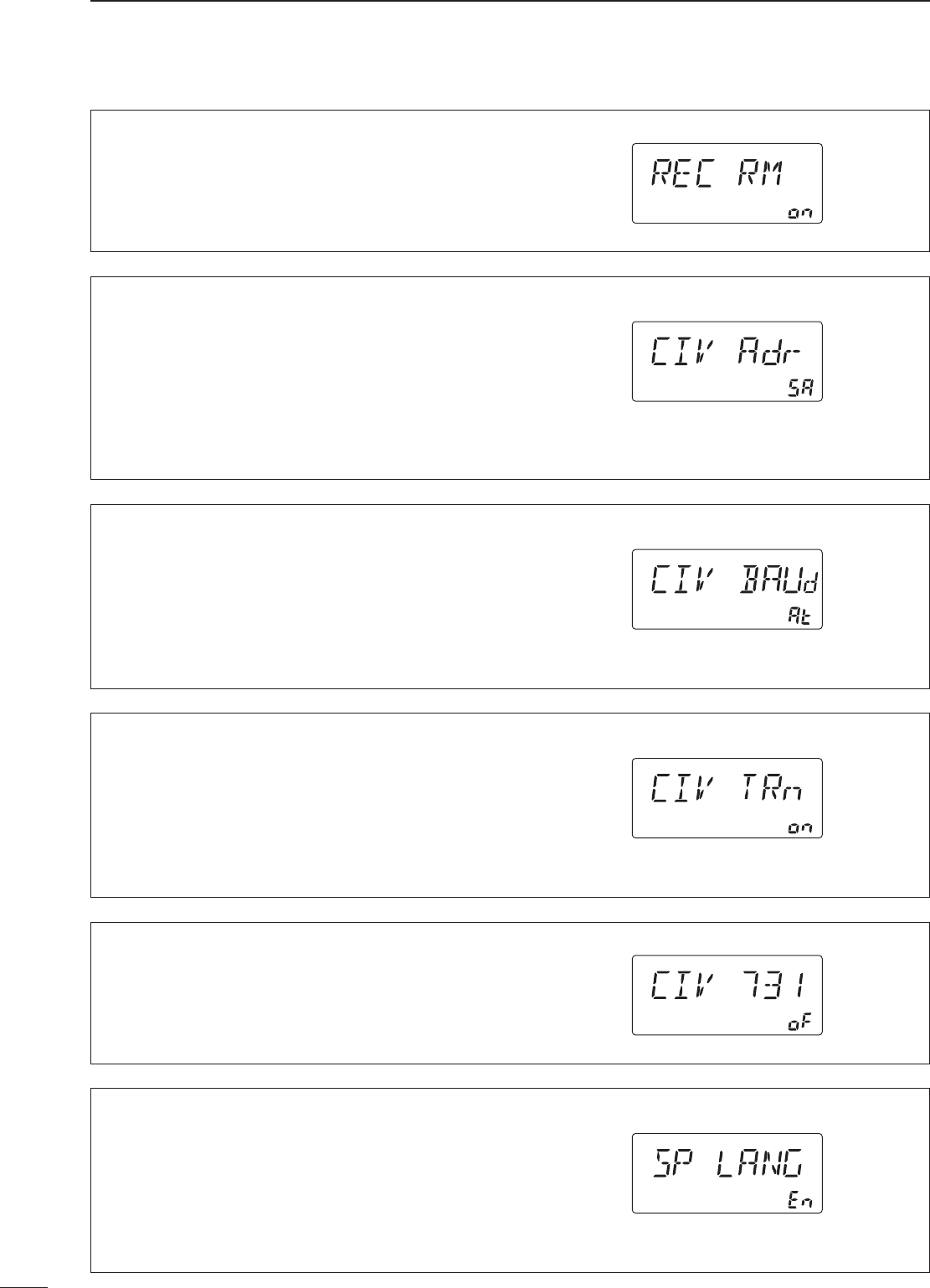
• Recorder remote
This item sets the [REC REMOTE] jack function ON
or OFF.
• CI-V address
To distinguish equipment, each CI-V transceiver
or receiver has its own Icom standard address in
hexadecimal code. The IC-R75’s address is 5Ah.
When 2 or more IC-R75’s are connected to an
optional CT-17 CI-V LEVEL CONVERTER, rotate the
tuning dial to select a different address for each
IC-R75 in the range 01h to 7Fh.
• CI-V baud rate
This item sets the data transfer rate. “3” (300 bps),
“12” (1200 bps), “48” (4800 bps), “96” (9600 bps),
“HI” (19200 bps) and “At” (automatic) are available.
When “At” is selected, the baud rate is automatically
set according to the connected controller or remote
controller.
• CI-V with IC-735
When connecting the IC-R75 to the IC-735 for
transceive operation, you must change the operating
frequency data length to 4 bytes.
• This item must be set to “ON” only when operating
receiver with the IC-735.
• Speech language
When the optional UT-102 VOICE SYNTHESIZER UNIT
is installed, you can select between English and
Japanese as the language.
• “En” English announcement
• “JP” Japanese announcement
See p. 34 for unit installation.
• CI-V transceive
Transceive operation is possible with the IC-R75
connected to other Icom HF transceivers or receivers.
When “on” is selected, changing the frequency,
operating mode, etc. on the IC-R75 automatically
changes those of connected transceivers (or
receivers) and vice versa.
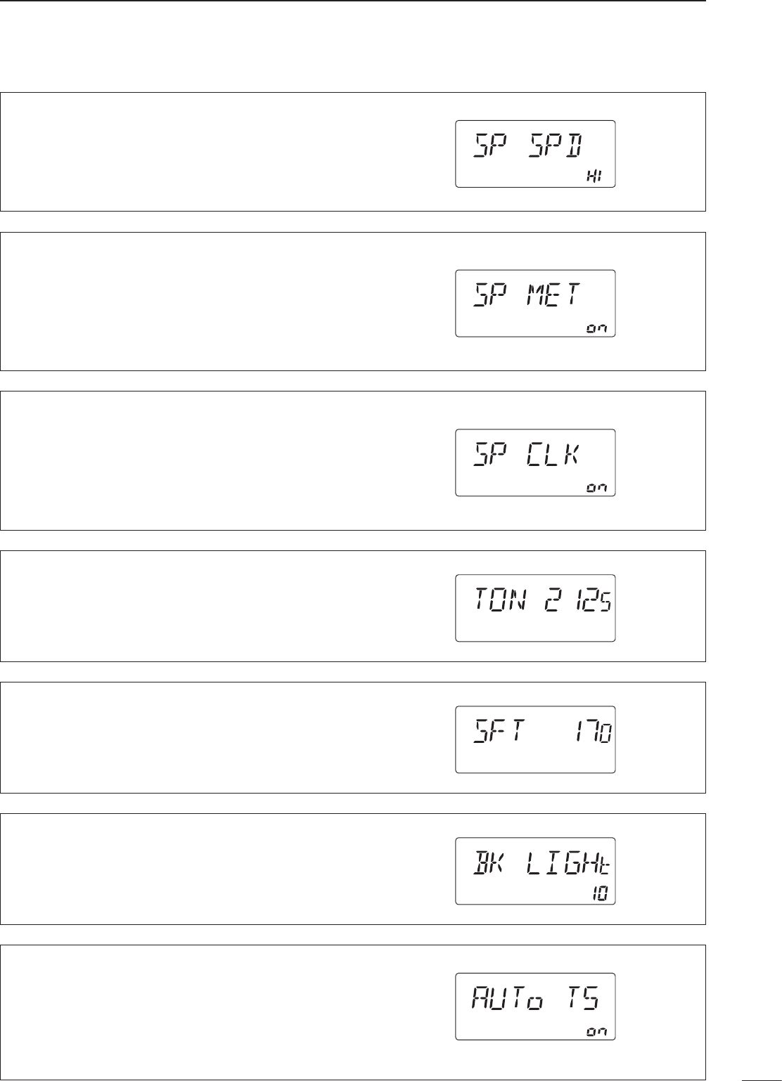
33
9
SET MODE
• Speech speed
When the optional UT-102 VOICE SYNTHESIZER UNIT
is installed, you can select between faster or slower
synthesizer output.
See p. 34 for unit installation.
• Speech S-level
When the optional UT-102 VOICE SYNTHESIZER UNIT
is installed, you can have signal level, frequency,
mode and current time announcement. Signal level
announcement can be deactivated if desired.
See p. 34 for unit installation.
• Speech current time
When the optional UT-102 VOICE SYNTHESIZER UNIT
is installed, you can have signal level, frequency,
mode and current time announcement. Current time
announcement can be deactivated if desired.
See p. 34 for unit installation.
• RTTY shift width
This item adjusts the RTTY shift width. There are 3
selectable values: 170, 200 and 425 Hz.
• LCD backlight
This item adjusts the brightness of the LCD from 0
% to 100 % in 1 % steps.
• The brightness is displayed in 10% steps. ‘5’ indicates
50% brightness.
• Auto tuning step
This item sets the auto tuning speed. The tuning dial
normally changes the frequency 2.5 kHz/revolution
in 10 Hz tuning step. When auto tuning speed is
turned on this increases to 50 kHz/revolution in 50
Hz tuning step during quick rotation of the dial.
• RTTY mark frequency
This item selects the RTTY mark frequency. RTTY
mark frequency is toggled between 1275, 1615 and
2125 Hz.
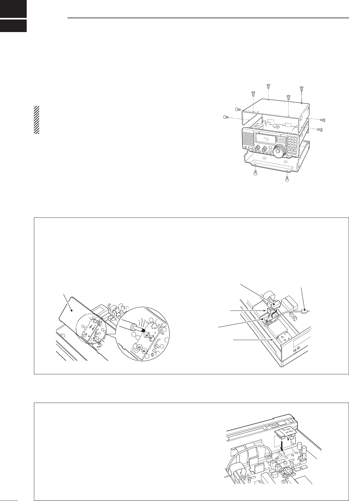
10
34
OPTION INSTALLATIONS
■ Opening the receiver’s case
Follow the case and cover opening procedures shown
here when you want to install an optional unit or
adjust an internal unit, etc.
CAUTION: DISCONNECT the DC power cable
from the receiver before performing any work on
the receiver. Otherwise, there is danger of electric
shock and/or equipment damage.
q Remove the 2 screws from the left side of the
receiver to remove an optional carrying handle, if
necessary.
w Remove the 4 screws from the top of the receiver
and 4 screws from the sides, then lift up the top
cover.
e Remove the 2 screws from the bottom of the
receiver, slide the cover backward, then remove
the bottom cover.
The UT-102 announces the received frequency, mode,
S-meter level and current time in a clear, electronically-
generated voice, in English (or Japanese).
➥ Push [LOCK] for 2 sec. to announce the
frequency, etc.
q Remove the top cover as shown above.
w Remove the protective paper attached to the
bottom of the UT-102 to expose the adhesive strip.
e Plug UT-102 into J1271 on the MAIN unit as
shown at right.
r Return the top cover to its original position.
■ CR-282 high stability crystal unit
By installing the CR-282, the total frequency stability
of the receiver will be improved.
q Remove the top cover as shown in the diagram
above.
w Remove 5 screws from the PLL unit, disconnect
P1 from J491 (MAIN unit), then remove the PLL
unit.
e Remove the supplied internal crystal and replace
with the CR-282.
r Adjust the reference frequency at L2 using a
frequency counter.
t Return the PLL unit and top cover to their original
positions.
PLL unit
MAIN unit
CR-282
Internal
crystal
Connect a frequency counter
here and adjust the frequency
to 60.00000 MHz.
L2
PLL unit
■ UT-102 voice synthesizer unit
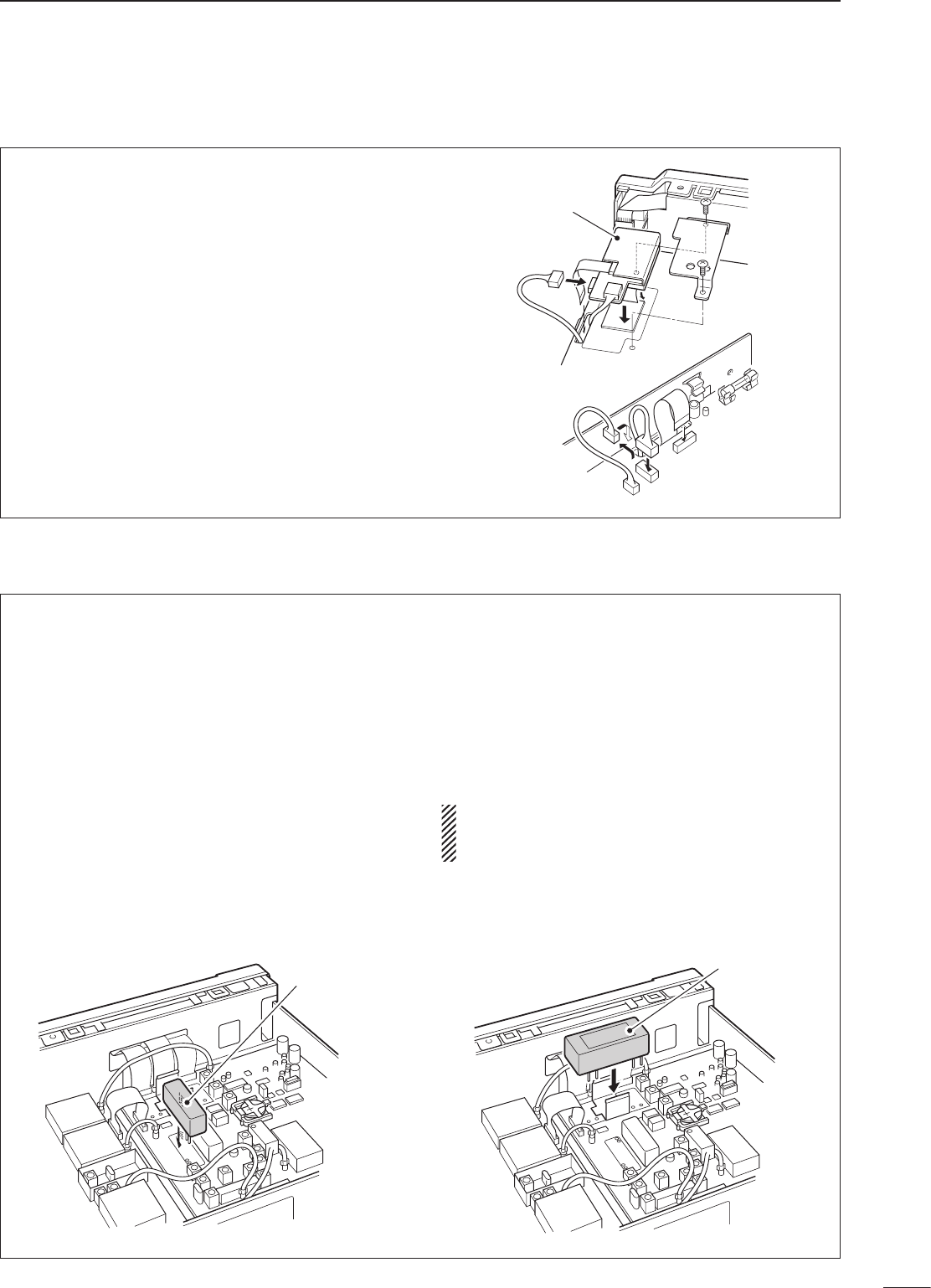
35
10
OPTION INSTALLATIONS
■ UT-106 dsp unit
■ Optional IF filters
The UT-106 provides AF DSP functions such as
noise reduction and auto notch.
q Remove the top and bottom covers.
w Remove the shielding plate.
e Remove the connection cable (P1241) from
J1221 on the MAIN unit. Connect the cable into
J1 on the UT-106.
r Plug the connection cable (P1) from the UT-106
to J1221 on the MAIN unit.
t Plug the flat cable into J3 on the UT-106 and to
J1231 on the MAIN unit.
• Take care of the conductor direction.
y Attach the Velcro tape as shown at right. Attach
the UT-106 to the reverse side of the MAIN unit.
u Return the shielding plate, top cover and bottom
cover to their original positions.
UT-106
P1241
P1241
J1221
J1231
J3
Several IF filters are available for the IC-R75. You
can install 1 filter for both 9 MHz and 455 kHz IF.
Choose appropriate filter for your operating needs.
9 MHz optional filters:
FL-101 cw narrow filter 250 Hz/–6 dB
FL-232 rtty/cw narrow filter 350 Hz/–6 dB
FL-100 cw narrow filter 500 Hz/–6 dB
FL-223 ssb narrow filter 1.9 kHz/–6 dB
FL-103 ssb wide filter 2.8 kHz/–6 dB
455 kHz optional filters:
FL-53A cw narrow filter 250 Hz/–6 dB
FL-52A cw/rtty narrow filter 500 Hz/–6 dB
FL-222 ssb narrow filter 1.8 kHz/–6 dB
FL-96 ssb wide filter 2.8 kHz/–6 dB
FL-257 ssb wide filter 3.3 kHz/–6 dB
D Installation
q Remove the top cover as shown on the opposite
page.
w Install the desired 9 MHz filter as shown in the
diagram below.
• The filters can be installed in either direction.
e Install the desired 455 kHz filter as shown in the
diagram below.
r Replace the top cover.
After filter installation, specify the installed filter
using filter set mode. (p. 19) Otherwise, the
installed filter will not function properly.
9 MHz filter
455 kHz filter
■ Resetting the CPU
Resetting CLEARS all programmed contents in
memory channels and returns programmed values
in set mode to their defaults.
When first applying power or when the function
seems to be displaying erroneous information, reset
the CPU as follows:
q Make sure receiver power is OFF.
w While pushing [UP Y] and [Z DN], push [POWER]
to turn power ON.
• The internal CPU is reset.
• The receiver displays its initial VFO frequencies when
resetting is complete.
11
36
MAINTENANCE
■ Troubleshooting
The following chart is designed to help you correct
problems which are equipment malfunctions.
If you are not able to locate the cause of a problem
or solve it through the use of this chart, contact your
nearest Icom Dealer or Service Center.
[POWER] [ZDN] [UPY]
PROBLEM POSSIBLE CAUSE SOLUTION REF.
POWER
Power does not come on
when the [POWER] switch
is pushed.
• DC power cable is improperly connected.
• Fuse is blown.
• Reconnect the DC power cable correctly.
• Check for the cause, then replace the fuse with
a spare one.
(Fuses are installed in the DC power cable
and the internal MAIN unit.)
—
p. 37
RECEIVE
No sound comes from the
speaker.
• Volume level is too low.
• The squelch is closed.
•Rotate [AF] clockwise to obtain a suitable
listening level.
• Rotate [RF/SQL] to 12 o’clock position to open
the squelch.
p. 2
p. 14
Sensitivity is low. • The antenna is not connected properly.
• The antenna for another band is selected.
• The attenuator is activated.
• Reconnect to the antenna connector.
•Select an antenna suitable for the operating
frequency.
• Push [ATT] to turn the function OFF.
—
p. 16
p. 16
Receive audio is distorted. • The operating mode is not selected correctly.
• PBT function is activated.
• Noise blanker function is activated.
• Preamp is activated.
• The optional noise reduction is activated and
the [NR] level is set too high.
• Select a suitable operating mode.
• Set [TWIN PBT] to the center position.
• Push [NB] to turn the function OFF.
• Push [P.AMP] once or twice to turn the function
OFF.
• Push [NR] to turn the function OFF.
p. 14
p. 15
p. 15
p. 16
p. 20
SCAN
Programmed scan does
not stop.
• Squelch is open.
• [RF/SQL] is assigned to RF gain control and
squelch is open.
• Set [RF/SQL] to the threshold point.
• Reset [RF/SQL] control assignment and set it to
the threshold point.
p. 14
pgs.
14, 30
Programmed scan does
not start.
• The same frequencies have been programmed
in scan edge memory channels P1 and P2.
•Program different frequencies in scan edge
memory channels P1 and P2.
p. 22
Memory scan does not
start.
•2 or more memory channels have not been
programmed.
• Program 2 or more memory channels. p. 22
Select memory scan does
not start.
•2 or more memory channels have not been
designated as select channels.
• Designate 2 or more memory channels as select
channels for the scan.
p. 26
DISPLAY
“F.AGC” flashes in the
function display.
• A scan or band scope function is activated via
an optional RS-R75 remote control software.
• If these functions are not in use, push [AGC] to
deactivate the function.
—
The displayed frequency
does not change properly.
• The dial lock function is activated.
• The internal CPU has malfunctioned.
• Push [LOCK] to deactivate the function.
• Reset the CPU.
p. 13
See
below.
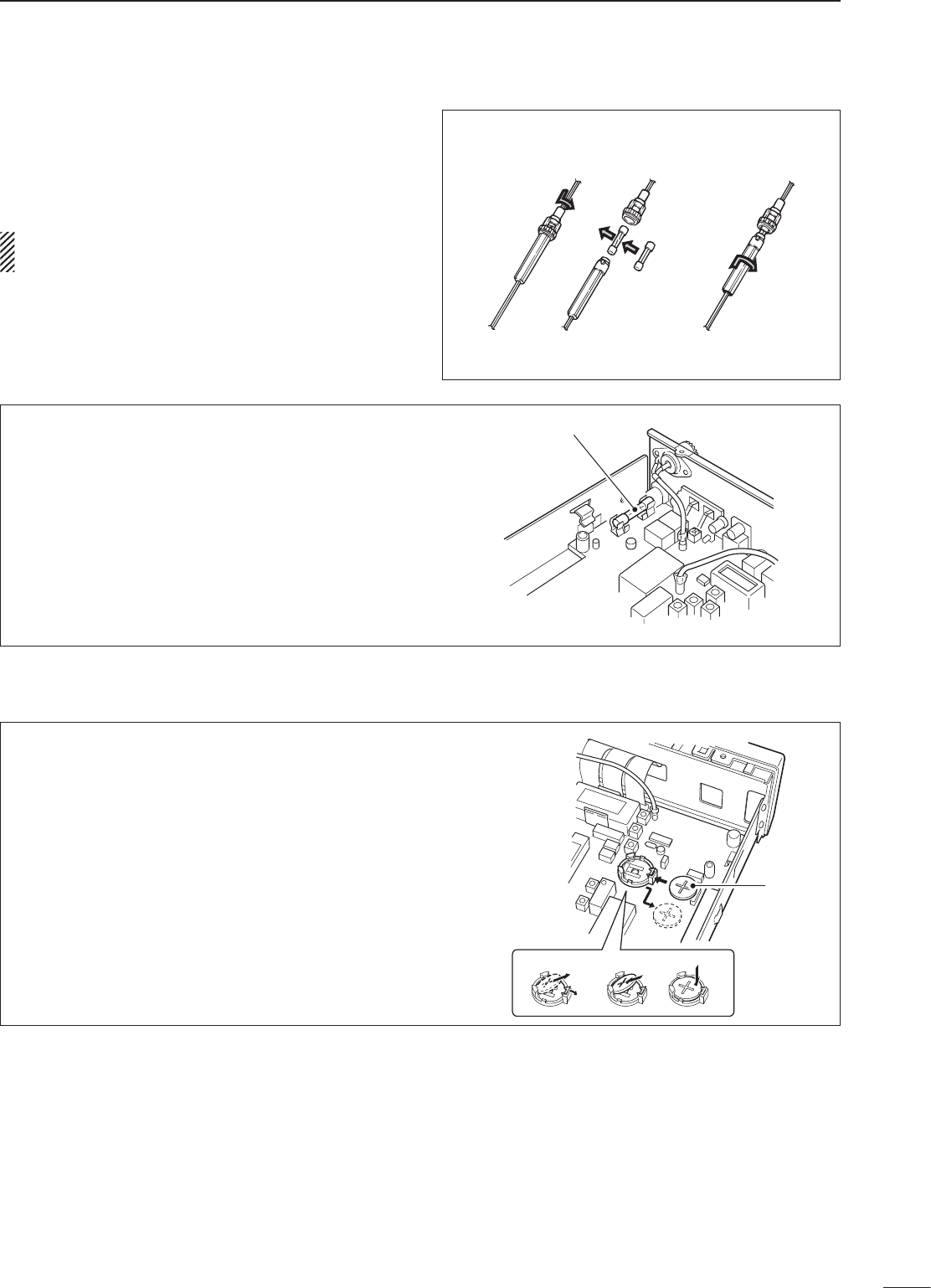
37
11
MAINTENANCE
CIRCUITRY FUSE REPLACEMENT
The 13.8 V DC from the DC power cable is applied
to all units in the IC-R75 through the circuitry fuse.
This fuse is installed in the MAIN unit.
q Remove the top cover as shown on p. 34
w Replace the circuitry fuse as shown in the
diagram at right.
e Replace the top cover.
FGB 3 A
■ Fuse replacement
If a fuse blows or the receiver stops functioning, try
to find the source of the problem, and replace the
damaged fuse with a new, rated fuse.
CAUTION: DISCONNECT the DC power cable
from the receiver when changing a fuse.
The IC-R75 has 2 types of fuses installed for receiver
protection.
• DC power cable fuses FGB 3 A
• Circuitry fuse FGB 3 A
DC POWER CABLE FUSE REPLACEMENT
3 A fuse
■ Clock backup battery replacement
The receiver has a lithium backup battery (CR2032)
inside for clock and timer functions. The usual life of
the backup battery is approximately 2 years.
When the backup battery is exhausted, the receiver
receives normally but cannot retain the current time.
CR2032
er
q
w

D General
• Frequency coverage : 0.03–60.000000 MHz*
* 0.03–29.999999 MHz only for Asia version; 0.03–
29.999999 and 50.0–52.0 MHz for Denmark version;
specifications guaranteed 0.1–29.99 MHz and 50–54
MHz only
• Mode : USB, LSB, CW, RTTY, AM,
FM
• Number of memory : 101 (99 regular, 2 scan edges)
channels
• Frequency stability : Less than ±7 ppm from 1
min. to 60 min. after power
on. After that rate of stability
less than ±1 ppm/hr. at +25
°C (+77°F). Temperature
fluctuations 0°C to +50°C
(+32°F to +122°F) less than ±
5 ppm.
• Power supply : 13.8 V DC ±15%
requirement (negative ground)
• Current drain : Standby 0.9 A
(at 13.8 V DC) Max. audio 1.1 A
• Antenna connector : SO-239 (50 Ω), push
connection terminal (500 Ω)
• Dimensions : 241(W)×94(H)×229(D) mm
(projections not included) 91⁄2(W)×311⁄16(H)×91⁄32(D) in
• Weight (approx.) : 3.0 kg; 6 lb 10 oz
• REMOTE connector : RS-232C D-sub 9-pin
• CI-V connector : 2-conductor 3.5 (d) mm (1⁄8˝)
D Receiver
• Receive system : Triple-conversion
superheterodyne system
• Intermediate frequencies:
* Frequencies differ according to the selected IF filter.
• Sensitivity :
*1 Preamp: OFF; *2 Preamp 1: ON; *3 Preamp 2: ON
• Squelch sensitivity (threshold):
SSB, CW, RTTY Less than 5.6 µV*1
FM Less than 0.32 µV*2
*1 Preamp 1: ON; *2 Preamp 2: ON
• Selectivity :
SSB, CW, RTTY More than 2.1 kHz/–6 dB
Less than 4.0 kHz/–60 dB
AM More than 6 kHz/–6 dB
Less than 20 kHz/–50 dB
FM More than 12 kHz/–6 dB
Less than 30 kHz/–40 dB
• Spurious and image rejection ratio:
More than 70 dB
(except IF through/50 MHz
band)
• Audio output power : More than 2.0 W at 10%
(at 13.8 V DC) distortion with an 8 Ω load
• PHONES connector : 3-conductor 6.35 (d) mm
(1⁄4˝)
• External SP connector : 2-conductor 3.5 (d) mm
(1⁄8˝)/8 Ω
12
38
SPECIFICATIONS
Mode 1st (MHz) 2nd (MHz) 3rd (kHz)
USB*/LSB* 69.0115 9.0115 455
CW* 69.0106 9.0106 455.9
RTTY* 69.0105 9.0105 456
AM* 69.0100 9.0100 450
FM 69.0115 9.0115 450
Frequency SSB/CW/RTTY AM FM
range 10 dB S/N 10 dB S/N 12 dB SINAD
0.1–1.8 MHz*1 2.0 µV 5.6 µV —
1.8–28 MHz*2 0.16 µV 1.6 µV —
28–29.99 MHz*2 0.16 µV 1.6 µV 0.22 µV
50–54 MHz*3 0.13 µV 1.0 µV 0.2 µV
All stated specifications are typical and subject to change without notice or obligation.
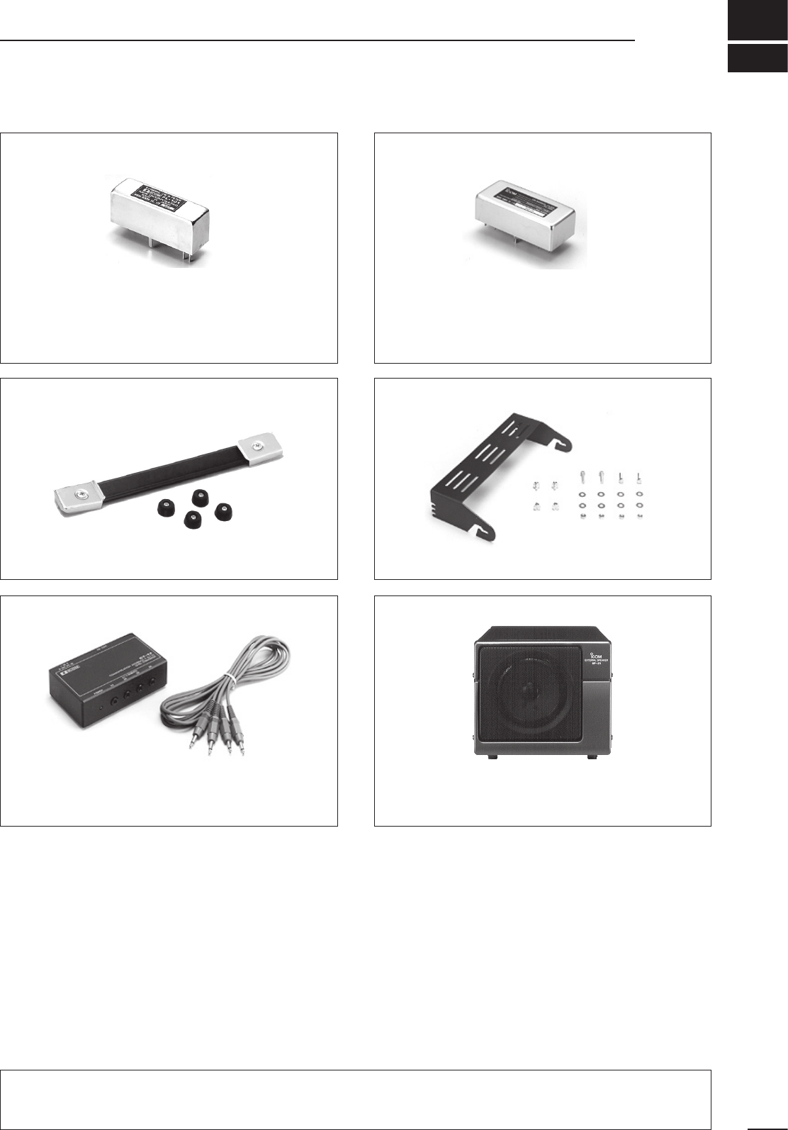
13
39
OPTIONS
FL-100, FL-101, FL-103, FL-223 and FL-232
9 MHz FILTERS
• FL-100: 500 Hz/–6 dB (CW/RTTY nar.)
• FL-101: 250 Hz/–6 dB (CW nar.)
• FL-103: 2.8 kHz/–6 dB (SSB wide)
• FL-223: 1.9 kHz/–6 dB (SSB nar.)
• FL-232: 350 Hz/–6 dB (RTTY/CW nar.)
FL-52A, FL-53A, FL-96, FL-222 and FL-257
455 kHz FILTERS
• FL-52A: 500 Hz/–6 dB (CW/RTTY nar.)
• FL-53A: 250 Hz/–6 dB (CW nar.)
• FL-96: 2.8 kHz/–6 dB (SSB wide)
• FL-222: 1.8 kHz/–6 dB (SSB nar.)
• FL-257: 3.3 kHz/–6 dB (SSB wide)
MB-23 CARRYING HANDLE
Carrying handle, convenient for portable operation.
IC-MB5 MOBILE MOUNTING BRACKET
Receiver mounting bracket for mobile operation.
CT-17 CI-V LEVEL CONVERTER
For remote receiver control using a PC. You can change
frequencies, operating mode, memory channels, etc.
SP-21 EXTERNAL SPEAKER
Designed for base station operation.
Input impedance: 8 Ω
Max. input power: 5 W
CR-282 HIGH-STABILITY CRYSTAL UNIT
Contains a temperature-compensating oven heater and
crystal unit for improved frequency stability.
• Frequency stability: ±0.5 ppm
RS-R75 REMOTE CONTROL SOFTWARE
Allows you to control the receiver from your PC (for
Microsoft® Windows® 95 or Windows® 98).
* S-AM (Synchronous AM) mode appears and can be selected on
the control screen, however, the receiver will function in normal
AM mode only.
UT-102 VOICE SYNTHESIZER UNIT
Announces the receive frequency, mode, S-meter level and
current time in a clear, electronically-generated voice, in
English (or Japanese).
UT-106 DSP UNIT
Provides AF DSP functions such as noise reduction and
auto notch.
Approved Icom optional equipment is designed for optimal performance when used with an Icom receiver.
Icom is not responsible for the destruction or damage to an Icom receiver in the event the Icom receiver is used
with equipment that is not manufactured or approved by Icom.
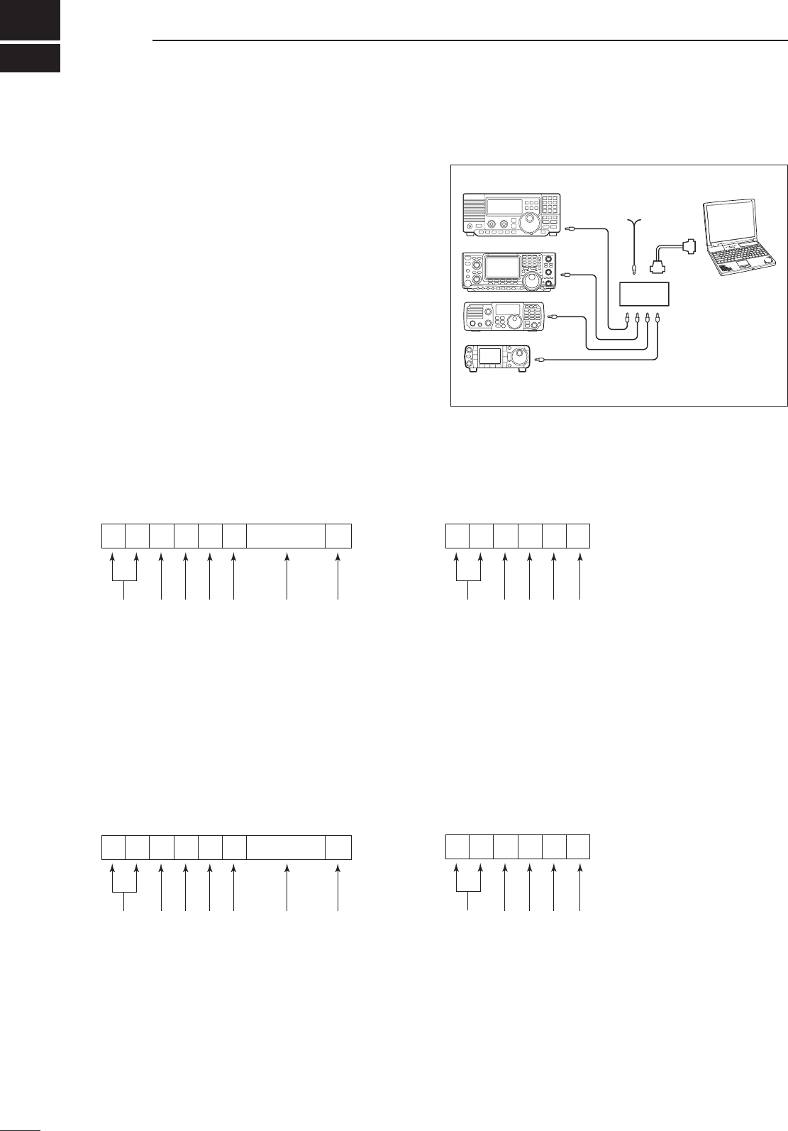
14
40
CONTROL COMMAND
• CI-V connection example
The receiver can be connected through an optional
CT-17 CI-V LEVEL CONVERTER to a PC equipped with an
RS-232C port. The Icom Communications Interface-V
(CI-V) controls the following functions of the receiver.
Up to 4 Icom CI-V transceivers or receivers can be
connected to a PC equipped with an RS-232C port.
See p. 32 for setting the CI-V condition using set
mode.
• Data format
The CI-V system can be operated using the following
data formats. Data formats differ according to
command numbers. A data area or sub command is
added for some commands.
CONTROLLER TO IC-R75
FE
FE
FE 5A E0 Cn Sc Data area FD
Preamble code (fixed)
Receiver’s default address
Controller’s default address
Command number
(see table at right)
Sub command number
(see table at right)
BCD code data for frequency or
memory number entry
End of message code (fixed)
OK MESSAGE TO CONTROLLER
FE FE E0 5A FB FD
Preamble code (fixed)
Controller’s default address
Receiver’s default address
OK code (fixed)
End of message code (fixed)
NG MESSAGE TO CONTROLLER
FE FE E0 5A FA FD
Preamble code (fixed)
Controller’s default address
Receiver’s default address
NG code (fixed)
End of message code (fixed)
IC-R75 TO CONTROLLER
FE E0 5A Cn Sc Data area FD
Preamble code (fixed)
Controller’s default address
Receiver’s default address
Command number
(see table at right)
Sub command number
(see table at right)
BCD code data for frequency or
memory number entry
End of message code (fixed)
q w e r t y u
q w e r t y u
■ Remote jack (CI-V) information
9–15 V DC
PC
ct-17
mini-plug cable
IC-R75
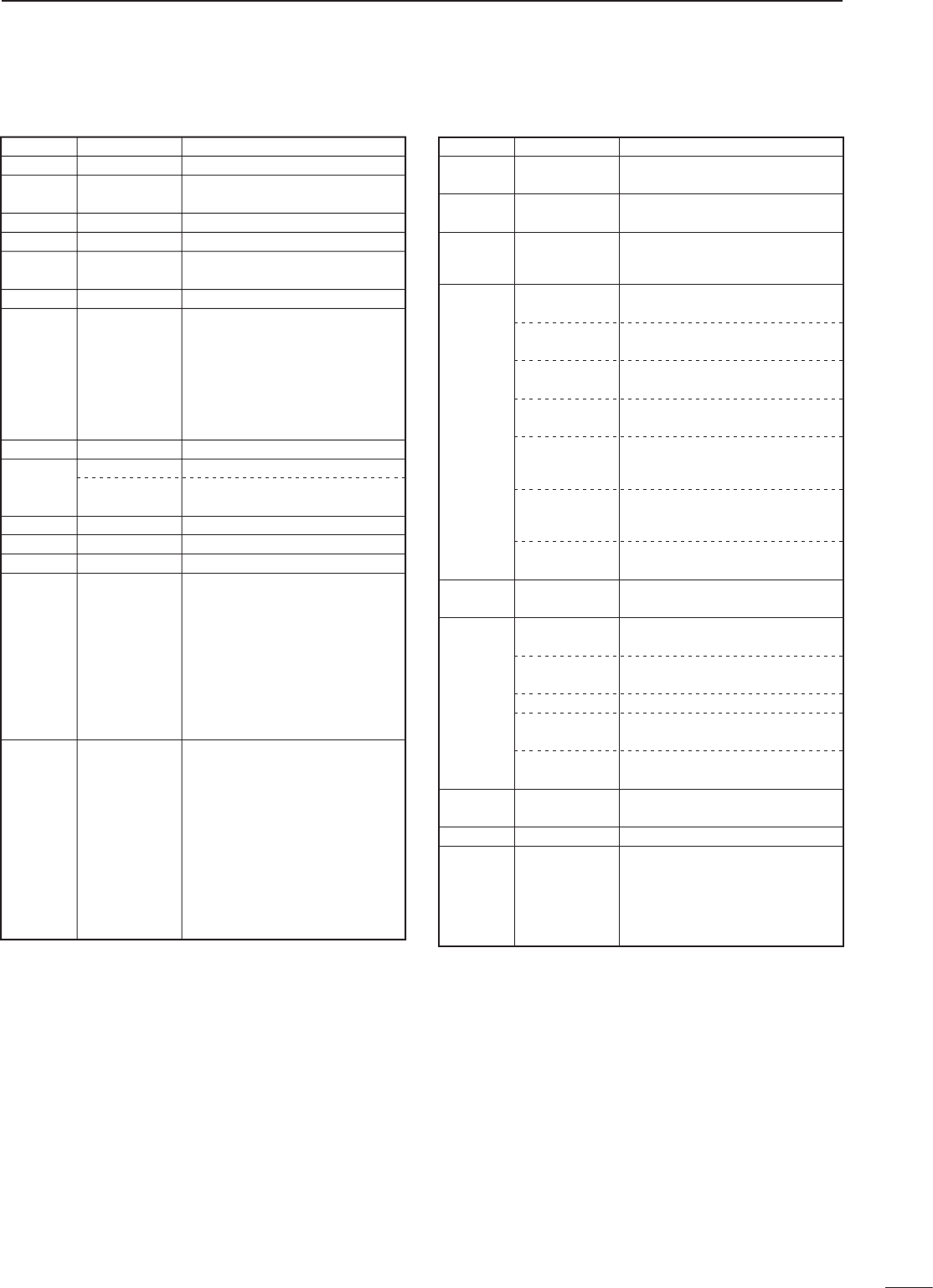
41
14
CONTROL COMMAND
• Command table
Sub commandCommand Description
—00 Send frequency data
Same as
command 06
Same as
command 06
01 Send mode data
—02 Read band edge frequencies
—03 Read operating frequency
04 Read operating mode
—05 Set frequency data
00*1
01*1
02*1
03*1
04*1
05*1
07*1
08*1
Set LSB
Set USB
Set AM
Set CW
Set RTTY
Set FM
Set CW-R
Set RTTY-R
06
*1Add 00, 01 or 02
for selecting wide,
normal or narrow
filter, respectively.
—
—
07 Select VFO mode
0001 – 0101*2
Select memory mode
Select memory channel
*2P1=0100, P2=0101
08
—09 Memory write
—0A Memory to VFO
—0B Memory clear
00
01
02
04
22
23
B0
B1
D0
D3
0E
Scan stop
Programmed/memory scan start
Programmed scan start
Auto memory write scan start
Memory scan start
Select memory scan start
Set as non-select channel
Set as select channel
Set scan resume OFF
Set scan resume ON
00
01
02
03
04
05
06
07
08
09
10
11
10
10 Hz (1 Hz) tuning step
100 Hz tuning step
1 kHz tuning step
5 kHz tuning step
6.25 kHz tuning step
9 kHz tuning step
10 kHz tuning step
12.5 kHz tuning step
20 kHz tuning step
25 kHz tuning step
100 kHz tuning step
1 MHz tuning step
Sub commandCommand Description
00
20
11 Attenuator OFF
Attenuator ON
Select [ANT1]
Select [ANT2]
00
01
12
Announce with voice synthesizer
(00=all data; 01=frequency and
S-meter level; 02=receive mode)
00
01
02
01 + level data
13
[CW PITCH] setting (0000=low
pitch to 0255=high pitch)
14
15
16
18
19
Read squelch condition
Read S-meter level
01
02
02
12
22
40
41
Set preamp (00=OFF;
01=preamp 1; 02=preamp 2)
Set AGC time constant (00=OFF;
01=S-fast; 02=fast; 03=slow)
Set noise blanker (00=OFF; 01=ON)
Set optional noise reduction
(00=OFF; 01=ON)
Set optional auto notch
(00=OFF; 01=ON)
Turn the receiver power ON
Turn the receiver power OFF
Read the receiver ID
Send/read memory contents
(See example 1 on p. 42)
Send/read IF filter setting
(See example 2 on p. 42)
Send/read set mode contents
(See example 3 on p. 43)
00
01
00
1A 00 + data
01 + data
02 + data
[AF] level setting (0000=max.
CCW to 0255=max. CW)
[RF] level setting (0000=max.
CCW to 0255=11 o’clock)
[SQL] level setting (0000=11
o’clock to 0255=max. CW)
[NR] level setting (0000=min. to
0255=max.)
Inside [TWIN PBT] setting
(0000=max. CCW, 0128=center,
0255=max. CW)
Outside [TWIN PBT] setting
(0000=max. CCW, 0128=center,
0255=max. CW)
09 + level data
08 + level data
07 + level data
06 + level data
03 + level data
02 + level data
42
14 CONTROL COMMAND
• CI-V data example 1
Reading/sending memory contents:
q Memory channel 39
w Select memory ch select ch
e Receive frequency 12.345678 MHz
r Receive mode FM
t IF filter Narrow
y Attenuator OFF
u Preamp Preamp 1
i Antenna selection ANT1
o Memory name DXSPOT 1
NOTE: When reading data, w – o are not required.
D X S P O T
Space
1
F D
FE F E 5 A E 0 1 A 0 0 0 0 3 9 7 8 5 6 3 4 1 2 0 0 0 5 0 3 0 0 0 1 0 0 4 4 8
5 5 3 5 0 F4 45 3 12 00 1
o
q
w
05 FM
07 CW-R
08
11
RTTY-R
S-AM
r
01
02
03
Wide
Normal
Narrow
t
y
00 OFF
20 ON
00 OFF
01 1
02 2
u
00 1
01 2
i
o
Memory name uses ASCII codes
• Space = 20h
• Numerals = 30h–39h,
• Alphabetical = 41h–5Ah
(except 7th and 8th digits)
• Non-named channel = FFh
0001 1 ch
99 ch
Data Mch
Data SEL
0100
0101
P1
P2
00 OFF
01 ON
00 LSB
01 USB
02
03
04
AM
CW
RTTY
10 Hz
1 Hz
1 kHz
100 Hz
100 kHz
10 kHz
10 MHz
1 MHz
1 GHz
100 MHz
… …
0099
Data Mode Data Mode Data IF filter
Data ATT Data ANT
Data P.AMP
q w e r t y u i
q w e r t y u
• CI-V data example 2
Reading/sending IF filter setting:
q Receive mode LSB/USB
w 9 MHz filter Normal 2.4 kHz
Narrow OFF
Wide 15 kHz
e 455 kHz filter Normal 6 kHz
Narrow 2.4 kHz
Wide 15 kHz
NOTE: When reading data, w and e are not required.
Data 9 MHz filter
q w
q
F D
FE F E 5 A E 0 1 A 0 1 0 0 0 2 0 7 0 4 0 0 0 00 1
wewewe
Normal Narrow Wide
e
Data
00
Mode
LSB/USB
01 CW/CW-R
02
03
RTTY/RTTY-R
AM
05 FM
00 15 kHz (built-in)
01 2.8 kHz (FL-103)
02
03
04
2.4 kHz (built-in)
1.9 kHz (FL-223)
500 Hz (FL-100)
05 350 Hz (FL-232)
06 250 Hz (FL-101)
07 OFF
Data
00
455 kHz filter
15 kHz (built-in)
01 6 kHz (built-in)
02
03
04
3.3 kHz (FL-257)
2.8 kHz (FL-96)
2.4 kHz (built-in)
05 1.8 kHz (FL-222)
06 500 Hz (FL-52A)
07 250 Hz (FL-53A)
q werty u
43
14
CONTROL COMMAND
• CI-V data example 3
Reading/sending set mode contents:
q Set mode number 21 (backlighting)
w Set data Set backlighting to a little on
the brighter side (180)
NOTE: When reading data, w is not required.
• Set mode data table
q
FE F E 5 A E 0 1 A 0 2 2 1 0 1 F D8 0
w
0 1
Type 1
w changes depending on the set mode contents.
Refer to the 'Type' in the table below.
0 1 8 0
Type 2 Type 3
1 5 5 0 0 0 1 4 3 0
Type 4
hr. min. hr. min.sec.
q w e r t y u
Set mode itemSet mode No (q) Selectable value Data range (w) Data type (w)
RF/squelch control
Confirmation beep
Beep level
Beep level limit
S-meter peak hold
Scan resume
Scan speed
AM mode noise blanker
CW pitch control
Blank channel indication
Recorder remote
CI-V transceive
CI-V with IC-735
Speech language
Speech speed
Speech S-level
Speech current time
RTTY mark frequency
RTTY shift width
LCD backlight
Auto tuning step
Memory name indication
Expanded filter selection
9 MHz optional IF filter
455 kHz optional IF filter
Set current time
Power-on timer
Set power-on time
Power-off timer
Set power-off time
Sleep timer
Set sleep time
OFF/ON
0 – 100%
0 – 100%
OFF/ON
OFF/ON
OFF/ON
Low/high
OFF/ON
300 Hz – 900 Hz
OFF/ON
OFF/ON
OFF/ON
OFF/ON
English/Japanese
Slower/Faster
OFF/ON
OFF/ON
OFF/ON
OFF/ON
Frequency indication/Memory name indication
0:00:00 – 23:59:59
OFF/ON
0:00 – 23:59
OFF/ON
0:00 – 23:59
OFF/ON
0:01 – 23:59
None/FL-100/FL-101/FL-103/FL-223/FL-232
None/FL-52A/FL-53A/FL-96/FL-222/FL-257
1275 Hz/1615 Hz/2125 Hz
170 Hz/200 Hz/425 Hz
Squech/Auto/RF gain + squelch01
02
03
04
05
06
07
08
16
17
18
19
10
11
12
13
14
15
26
27
28
29
20
21
22
30
31
32
33
23
24
25
1
00/01/02
00/01
0000 – 0255
00/01
00/01
00/01
00/01
00/01
0300 – 0900
00/01
00/01
00/01
00/01
00/01
00/01
00/01
00/01
00/01/02
00/01/02
0000 – 0255
00/01
00/01
00/01/02/03/04/05
00/01/02/03/04/05
00/01
00/01
00/01
00/01
1
2
1
1
1
1
1
2
1
1
1
1
1
1
1
1
1
1
2
1
1
1
1
1
3
1
4
1
4
1
4
000000 – 235959
0000 – 2359
0000 – 2359
0001 – 2359
1-1-32 Kamiminami, Hirano-ku, Osaka 547-0003, Japan
A-5580H-1EX-t
Printed in Japan
© 1999–2009 Icom Inc.
Printed on recycled paper with soy ink.