ICOM orporated IC-T7H Amateur Radio Equipment User Manual IC T7H
ICOM Incorporated Amateur Radio Equipment IC T7H
UserManual.wiki
>
ICOM orporated
>
IC T7H User Manual
manual
Navigation menu
Upload a User Manual
Namespaces
Wiki Guide
HTML
PDF
Info
Views
User Manual
Discussion / Help
Navigation
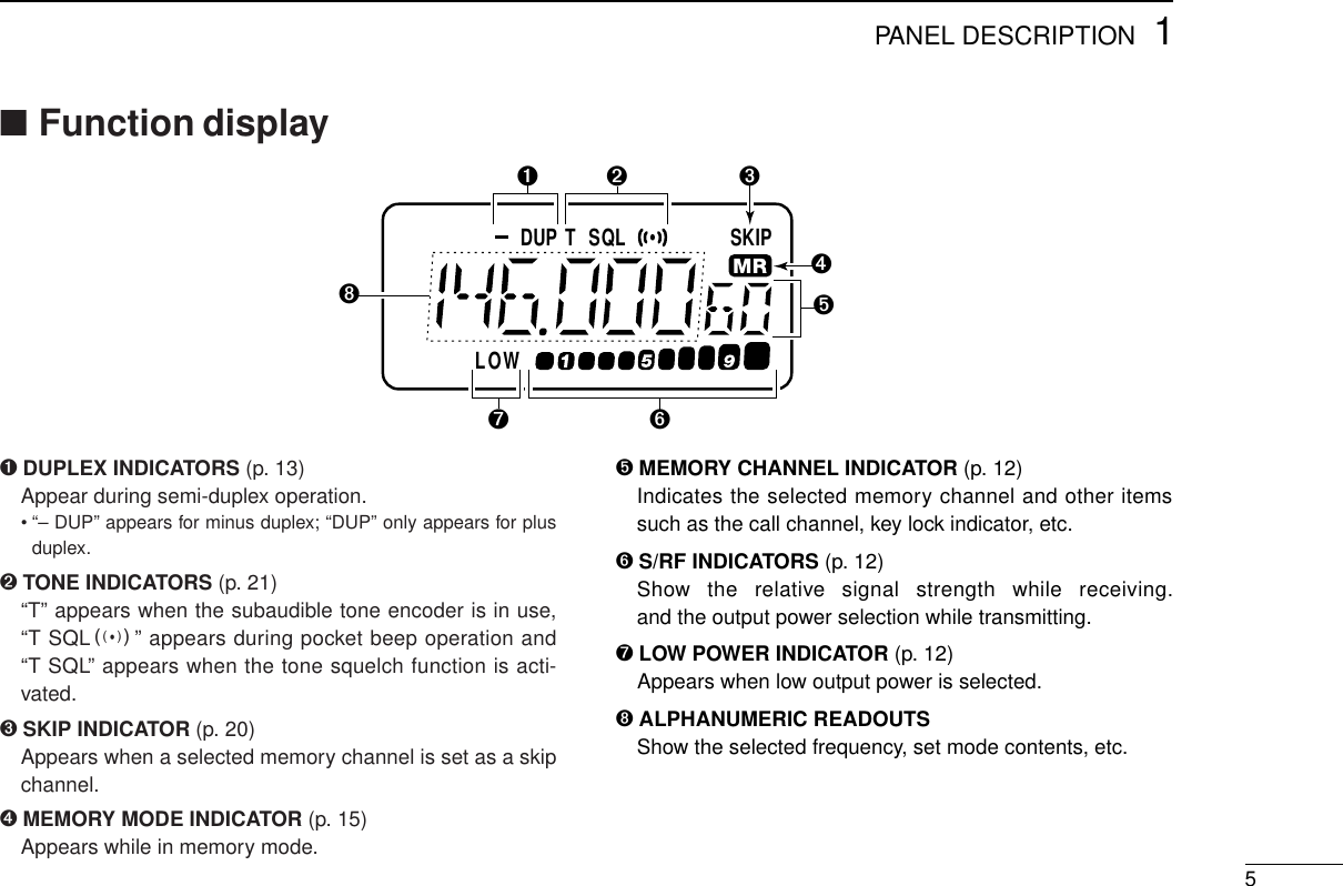
![PANEL DESCRIPTION 111[PTT]@[BAND]A[H/L]B[TONE]IJ[DC13.5V]6[VOL]9[POWER]7[RX/TX]2[LOCK]8[MONI]4[SP/MIC]35[DIAL]CDEFGHKCLR MHzSKIPMWVFOMRCALLS.MWABCDDTMF•M.T SCANPOWERSCANDUP SETBANDTONEH LLOCKMONI■Switches, controls, keys and connectors](https://usermanual.wiki/ICOM-orporated/IC-T7H/User-Guide-15465-Page-5.png)
![1PANEL DESCRIPTION2➏VOLUME CONTROL [VOL]Rotate [VOL] clockwise to increase volume and counter-clockwise to decrease volume.➐RX/TX INDICATOR [RX/TX] (p. 12)Lights green while receiving a signal or when the squelch isopen; lights red while transmitting.➑MONITOR SWITCH [MONI] (p. 12)➥Push and hold this switch to force the squelchopen; release to close it again.➥Push twice to keep the squelch open; push againto close it.➥While pushing this switch, rotate [DIAL] to set thesquelch level.➥While pushing [PTT], push this switch to transmita DTMF memory.➒POWER SWITCH [POWER]Push for 1 sec. to toggle power ON and OFF.• Battery voltage appears for 1 sec. after power ON.➓BAND SWITCH [BAND/SCAN]➥Push to toggle between VHF and UHF operationexcept in memory mode (p. 10).➥Push and hold to indicate the selected scanrange (or band) and to start scanning (p. 18).• While scanning, each push of this switch changes theselected scan range.SCANBANDPOWERMONI➊PTT SWITCH [PTT] (p. 12)Push and hold to transmit; release to receive.➋LOCK SWITCH [LOCK]Slide up to turn the lock function ON.• [PTT], [VOL], [H/L], [MONI] and [POWER] function evenwhen the lock function is activated.➌ANTENNA CONNECTOR (p. 9)Connects the supplied antenna.➍EXTERNAL SPEAKER AND MICROPHONE JACKS[SP/MIC]Connect an optional speaker-microphone or headset, if de-sired. The internal microphone and speaker will not func-tion when either is connected. (See p. 28 for options.)DExternal connection➎TUNING DIAL [DIAL]Rotate [DIAL] to set an operating frequency, select a mem-ory channel, select set mode contents, change scan direc-tion, etc.This connec-tion does not apply when a condensor mi-crophone is connected.Remote Audio out(8 Ω)[SP]MIC3.5 VPTT[MIC] Audio inputPTT33 kΩ(2 kΩ)](https://usermanual.wiki/ICOM-orporated/IC-T7H/User-Guide-15465-Page-6.png)
![1PANEL DESCRIPTION3!1 OUTPUT POWER SWITCH [H/L(SET)]➥Push to toggle between low and high outputpower (p. 12).• “LOW” appears when low output power is selected.➥Push and hold to enter set mode.!2 TONE SWITCH [TONE(DUP)]➥Push this switch to activate the following func-tions in order (pgs. 21, 22).• Subaudible tone encoder—“T” appears.• Pocket beep—“T SQLS” appears.• Tone squelch—“T SQL” appears.• No tone operation—no indicator appears.➥Push this switch for 1 sec. to select semi-duplexor simplex operation (p. 13).• “– DUP” appears during minus duplex operation,“DUP” appears during plus duplex operation and noindicator appears during simplex operation.➥For the European version only, while pushing[PTT], push this switch to transmit a 1750 Hztone burst signal (p. 13).!3 VFO/CLEAR KEY [VFO(CLR MHz);;]➥Clears some functions, such as digit input beforeentry, scan, etc.➥Push this key to select VFO mode (p. 10).➥Push and hold for 1 sec., then rotate [DIAL] tochange the MHz digit (p. 11).➥While pushing [PTT], this key sends a DTMF “A.” CLR MHzVFOADUPTONESETH L!4 MEMORY MODE KEY [MR(SKIP)<<]➥Push this key to select memory mode (p. 12).•“XX” appears while in memory mode.➥While in memory mode, push this key for 1 sec.to toggle the selected memory channel betweena skip and a non-skip channel (p. 20).• “SKIP” appears when the channel is set as a skipchannel.➥While pushing [PTT], this key sends a DTMF “B.” !5 CALL MODE KEY [CALL==]➥Push this key to select the call channel (p. 15).• “C” appears while the call channel is selected.➥While pushing [PTT], this key sends a DTMF “C.” !6 SELECT MEMORY WRITE KEY [S.MW(MW)>>](pgs. 15, 16)➥Push this key to enter memory select mode.•“X” flashes and the [DIAL] can be used for channelselection (for memory writing or clearing).➥Push and hold for 1 sec. to write the set contentsinto the selected memory channel (or VFO, callchannel).➥Push then push and hold this key while in mem-ory select mode to erase the contents of the se-lected memory channel.➥While pushing [PTT], this key sends a DTMF “D.”MWS.MWDCALLCSKIPMRB](https://usermanual.wiki/ICOM-orporated/IC-T7H/User-Guide-15465-Page-7.png)
![1PANEL DESCRIPTION4!7 TONE SCAN KEY [TSCAN?]➥Push this key for 1 sec. to start and stop tone de-code scan (p. 13).• When a subaudible tone is detected, the tone fre-quency is displayed and overwrites the prepro-grammed:➠tone squelch frequency when the tone squelch isin use;➠tone encoder (repeater tone) frequency when thetone squelch is not in use.➥While pushing [PTT], this key sends a DTMF “#.” !8 DTMF KEY [• (DTMF M@)]➥Enters a decimal for MHz unit during frequencyinput (p. 10).➥Push and hold for 1 sec. to enter DTMF memorymode for programming or recall (p. 17).• To program use [(H/L)SET].• To transmit use [MONI] while transmitting.➥While pushing [PTT], this key sends a DTMF “M.”!9 DIGIT KEYS➥Input the specified digit during frequency input, memorychannel selection, etc.➥Transmit the DTMF code of the specified digit whilepushing [PTT].DTMF•M.T SCAN@0 EXTERNAL DC POWER JACK [DC13.5V]Allows operation with a 4.5 to 16 V DC power source usingthe optional cables, CP-12L or OPC-254L.CAUTION: Operation with an external DC powersource simultaneously charges batteries inside the bat-tery case or the battery pack. When using dry cell bat-teries this may cause battery leakage and damage thetransceiver; when using a Ni-Cd battery pack this maycause battery overcharging and shorten the life of thebattery pack.@1 BATTERY PACK RELEASE (p. 8)Push to open the latch for battery pack removal.](https://usermanual.wiki/ICOM-orporated/IC-T7H/User-Guide-15465-Page-8.png)
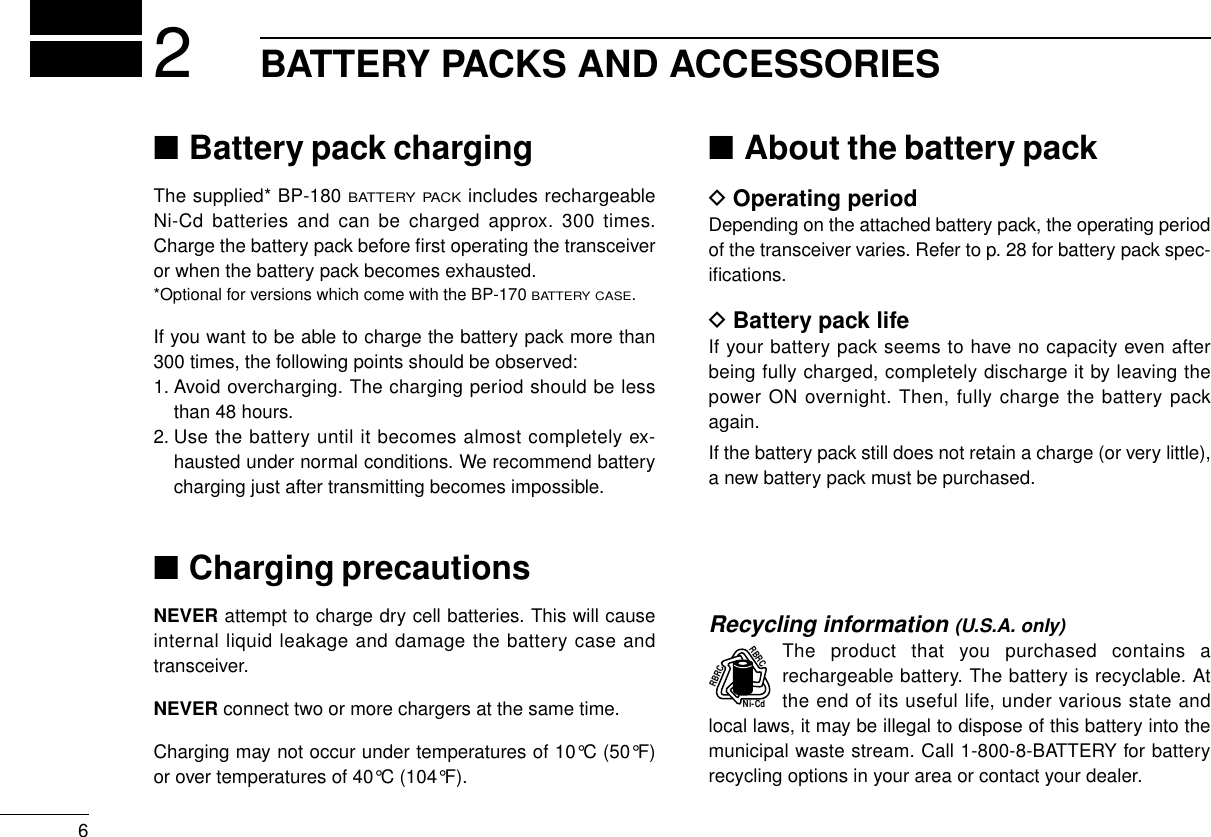
![72BATTERY PACKS AND ACCESSORIES■Charging connectionsDRegular chargingAttach the supplied* or optional battery pack; then, connectthe supplied* wall charger via an AC outlet as shown below.*Optional for versions which include a battery case.DRapid charging with the BC-119➀Insert the AD-56A into the charging slot of the BC-119.➁Insert the AD-56B into the groove in the AD-56A (front-fac-ing side of the AD-56A).➂Insert the battery pack, either by itself or attached to thetransceiver, into the AD-56B.To [DC13.5V]Wall chargerBP-171 orBP-172attached tothe transceiver Check orientationfor correctchargingBP-171 orBP-172WITHOUTtransceiverBP-173 orBP-180WITHor WITHOUTtransceiverAD-56(optional)BC-119(optional) Charging periods:1 hour (w/BP-171or BP-180)1.5 hours (w/BP-172 or BP-173)Charging periods:15 hours (w/BP-171, BP-173 or BP-180)20 hours (w/BP-172)](https://usermanual.wiki/ICOM-orporated/IC-T7H/User-Guide-15465-Page-11.png)
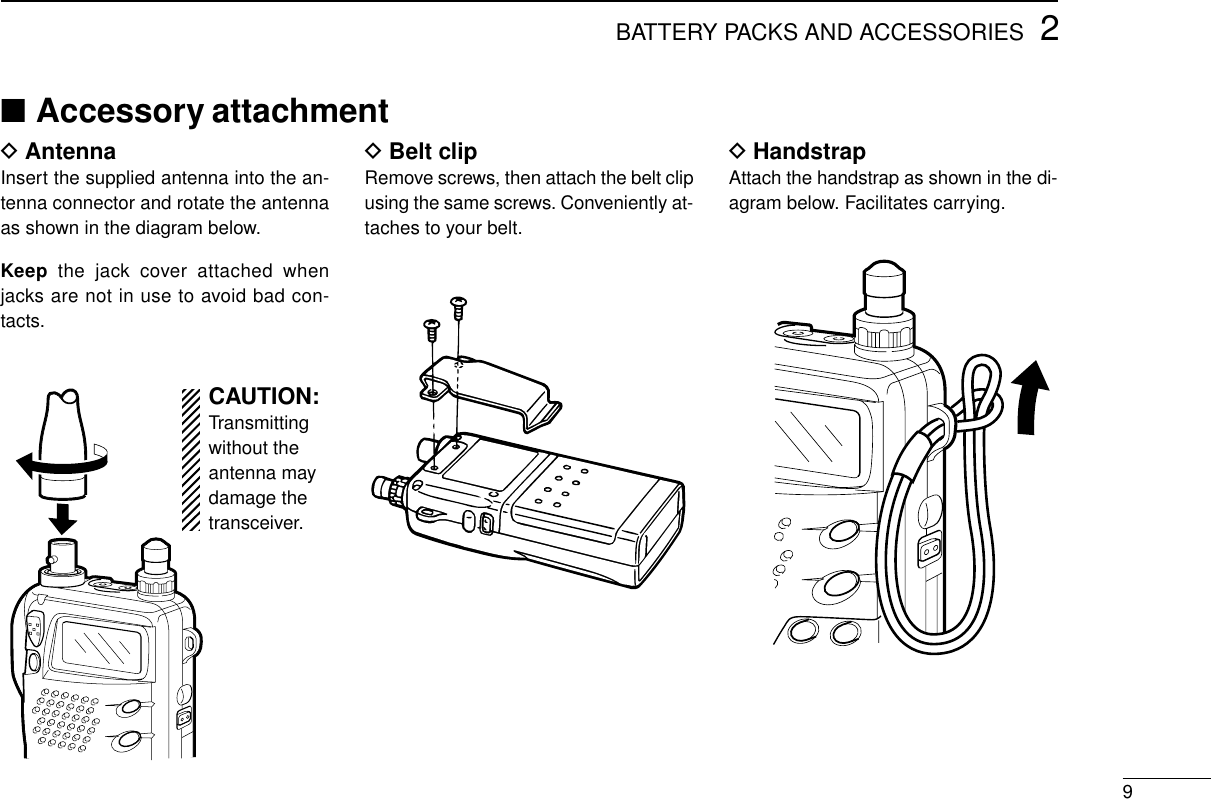
![82BATTERY PACKS AND ACCESSORIESDOperation with an optional cableConnect an optional charger or cable to the transceiver as il-lustrated below. Be careful of battery overcharging as the con-nected battery is charged simultaneously.■Battery caseWhen using a battery case attached to the transceiver, install4 AA(R6) size alkaline batteries as illustrated below.CAUTION: Remove dry cell batteries when the BP-170BATTERY CASEis connected, otherwise the battery mayleak and damage the transceiver.Open the case.Remove the casefrom the transceiver.Install 4 AA(R6) size drycell batteries into thebattery case.CP-12L(optional)OPC-254L(optional)To a cigarettelighter socketTo a 4.5 to 16* V DCpower sourceTo[DC13.5V]whiteblack*To charge the battery pack12 to 16 V DC is necessary.](https://usermanual.wiki/ICOM-orporated/IC-T7H/User-Guide-15465-Page-12.png)
![103BASIC OPERATION■Power ONPush and hold [POWER]for 1 sec. to turn powerON.• Current battery voltage isdisplayed for 2 sec.• The display shows the approx. volt-age in 0.5 V steps.• When the battery voltage is lowerthan 4.5 V, “LOW V” appears. Chargethe battery in this case.• If “OVER V” appears, UNPLUG theexternal DC plug immediately. Con-nected voltage is over 16 V and coulddamage the transceiver.■Setting a frequencyDVia the keypad (within a band)➀Push [VFO] to select VFOmode.➁Push [BAND] to select theVHF or UHF band.➂Push 4 digit keys, startingfrom the 1 MHz digit and in-cluding the decimal point [•],to input a frequency.• When a digit is mistakenlyinput, push [VFO] and inputfrom the beginning.• “0,” “2,” “5” and “7” are accept-able for the 1 kHz digits (de-pending on the 10 kHz digit).➃To change the frequencyfrom the 100 kHz digit, push[•], then 3 digits.for 1 sec.after 2 sec.POWER3655000..Push for1 sec.](https://usermanual.wiki/ICOM-orporated/IC-T7H/User-Guide-15465-Page-14.png)
![3BASIC OPERATION11■Setting tuning stepsThis transceiver has 8 tuning steps (VHF and UHF bandshave independent settings) as follows:• 5 kHz • 10 kHz • 12.5 kHz • 15 kHz• 20 kHz • 25 kHz • 30 kHz • 50 kHz➀Push [VFO] to select VFO mode.➁Push [BAND] to select the VHF or UHF band.➂Push [(H/L)SET] for 1 sec. to enter set mode.➃Push [TONE] or [H/L] several times until “TS” appears.➄Rotate [DIAL] to select the desired tuning step.➅Push [(VFO)CLR] to exit set mode.For convenience, select a tuning step that matches the fre-quency intervals of repeaters in your area.[DISPLAY EXAMPLE]15 kHz tuning step 25 kHz tuning stepUSINGSET MODEDVia the keypad (other band directly)➀Push [VFO] to select VFOmode.➁Push 6 digit keys, startingfrom the 100 MHz digit.• The operating band changesautomatically.• It’s not necessary to input thedecimal point.DOther methods➥VIA THE DIAL: Rotate [DIAL] to change the frequency ac-cording to the set tuning steps.➥USING THE MHz STEP: Push [(VFO)MHz] for 1 sec., thenrotate [DIAL] to change the frequency in one MHz steps.000044](https://usermanual.wiki/ICOM-orporated/IC-T7H/User-Guide-15465-Page-15.png)
![■Receive and transmit➀Push [POWER] for 1 sec. to turn power ON.➁Adjust the [VOL] control to the desired level.• While pushing [MONI], rotate [VOL].➂Set the squelch level.• While pushing [MONI], rotate [DIAL].• 4 selections are available, “OP”(open), “AT” (automatic), 1 and 2.➃Set an operating band and frequency.When a signal is received:➥Squelch opens and audio is emitted from the speaker.➥The S/RF indicator shows the relative signal strength.➄Push [H/L] to toggle output power between high and low.• “LOW” appears when low output power is selected.➅Push and hold [PTT] to transmit; then speak into the mic.•Do not hold the microphone too close to your mouth or speaktoo loudly. This may distort the signal.• The TX/RX indicator lights red.• The S/RF indicator shows the output power selection.➆Release [PTT] to return to receive.✔CONVENIENTMonitor function: Push and hold [MONI] to listen to weaksignals that do not open the squelch; or push [MONI] twice tomonitor a signal without having to continuously hold [MONI].Squelch control: The transceiver employs a noise pulsecount systemand therefore, squelch is adjusted automati-cally, when “AT” is selected.123BASIC OPERATION■Selecting a memory channel➀Push [MR] to select memorymode.➁Push 2 digit keys to selectthe desired memory channel(or rotate [DIAL]).• The first nine memory chan-nels are preceded by a “0.”• To select scan edges 1A to 4B,use [@] for “A” and [?] for “B.”• Only programmed memorychannels can be selected.■Lock functionThe lock function prevents accidental frequency changes andaccidental function activation.➥Slide [LOCK] up or down to set thelock function ON or OFF, respec-tively.• “L” appears while the lock function isactivated.• [PTT], [POWER], [VOL], [MONI], and[H/L] can be used regardless of this setting.MRMRMRMR60](https://usermanual.wiki/ICOM-orporated/IC-T7H/User-Guide-15465-Page-16.png)
![3BASIC OPERATION13■Repeater operationDGeneralWhen using a repeater, the transmit frequency is shifted fromthe receive frequency by the offset frequency. It is convenientto program repeater information into memory channels(p. 15).➀Set the operating band and receive frequency (repeateroutput frequency).➁Push [(TONE)DUP] for 1 sec. once to select – DUP or twiceto select DUP.• “– DUP” or “DUP” appears to indicate the transmit frequency forminus shift or plus shift, respectively.• When the auto repeater function is in use (U.S.A. version only)this selection and step ➂are not necessary (p. 24).➂Push [TONE] to activate the subaudible tone encoder, ac-cording to repeater requirements.• “T” appears.• Refer to the table of tone frequencies on the following page.➃Push and hold [PTT] to transmit.• The displayed frequency automatically changes to the transmitfrequency (repeater input frequency).• If “OFF” appears, check the offset frequency (p. 14).➄Release [PTT] to receive.➅Push and hold [MONI] to check whether the other station’stransmit signal can be directly received or not.DTone informationSome repeaters require a tone to be accessed. In this case,precede step ➃at left with the required tone.DTMF TONES (U.S.A. and Asia versions only)While pushing [PTT], push the desired digit key(s) to transmitDTMF tones• The transceiver has 9 DTMF memory channels. See p. 17 for de-tails.1750 Hz TONE (Europe and Italy versions only)While pushing [PTT], push and hold [TONE] for 1 to 2 sec. totransmit a 1750 Hz tone signal.✔CONVENIENTTone scan function:When you don’t know the subaudibletone used for a repeater, the tone scan is convenient for de-tecting the tone frequency.Push and hold [T SCAN?] to activate. See p. 22 for more in-formation.](https://usermanual.wiki/ICOM-orporated/IC-T7H/User-Guide-15465-Page-17.png)
![3BASIC OPERATION14DSetting subaudible tones forrepeater useSome repeaters require subaudible tones to be accessed.Subaudible tones are superimposed over your normal signaland must be set in advance.➀Push [VFO] to select VFO mode.➁Push [BAND] to select VHF or UHF.➂Push [(H/L)SET] for 1 sec. to enterset mode.➃Push [TONE] or [H/L] several timesuntil “rT” appears.➄Rotate [DIAL] to select the desiredsubaudible tone.➅Push [(VFO)CLR] to exit set mode.•Available subaudible tone frequencies (unit: Hz)TT67.0 79.7 94.8 110.9 131.8 156.7 171.3 186.2 203.5 229.169.3 82.5 97.4 114.8 136.5 159.8 173.8 189.9 206.5 233.671.9 85.4 100.0 118.8 141.3 162.2 177.3 192.8 210.7 241.874.4 88.5 103.5 123.0 146.2 165.5 179.9 196.6 218.1 250.377.0 91.5 107.2 127.3 151.4 167.9 183.5 199.5 225.7 254.1USINGSET MODEDSetting an offset frequencyWhen communicating through a repeater, the transmit fre-quency is shifted from the receive frequency by an amountdetermined by the offset frequency.➀Push [VFO] to select VFO mode.➁Push [BAND] to select VHF or UHF.➂Push [(H/L)SET] for 1 sec. to enterset mode.➃Push [TONE] or [H/L] several timesuntil “OW” appears.➄Rotate [DIAL] to select the desiredoffset.• Selectable steps are the same as thepre-set tuning steps.• MHz step may be helpful for large frequency changes—push[(VFO)MHz] for 1 sec.➅Push [(VFO)MHz] to exit set mode.■Auto low powerWhen transmitting for 6 continuous min. at high power, theIC-T7H automatically selects low power. This function cannotbe turned OFF and activates when the power supply is at ap-prox. 11 V or more. To return to high power on transmit, selectreceive, then switch back to transmit.DUPDUPUSINGSET MODE](https://usermanual.wiki/ICOM-orporated/IC-T7H/User-Guide-15465-Page-18.png)
![ADVANCED FUNCTIONS 415DProgramming during selection➀Push [VFO] to select VFO mode.➁Set the desired frequency:➥Set other data, such as re-peater information, etc. usingset mode if required.➂Push [S.MW] momentarily.•“X” flashes.• Do not hold [S.MW] for more than 1sec., otherwise the memory channelwill overwrite the displayed number.➃Rotate [DIAL] to select the desiredchannel.• Call channel and scan edge channels,as well as regular memory channels,can be programmed in this way.• If you want to confirm the VFO fre-quency, push [S.MW] momentarily.➄Push [S.MW] for 1 sec. to program.•“X” stops flashing.DLOWUPDLOWUPDLOWUPDLOWUPMRMR■Memory/call channelsThe transceiver has 70 memory channels (60 regular, 4 pairsof scan edge channels for mixed bands and 1 call channel foreach band). Note that memory channels are not grouped ac-cording to band. In other words, a given memory channel canbe programmed with either a VHF frequency or a UHF fre-quency. This is not the case with call channels. Call channelsare band specific.The following can be programmed into memory/call channels:• Operating frequency• Duplex direction with an offset frequency (pgs. 13, 14)• Subaudible tone encoder or tone squelch ON/OFF with atone (CTCSS) frequency (pgs. 21, 22)• Skip information (p. 20)](https://usermanual.wiki/ICOM-orporated/IC-T7H/User-Guide-15465-Page-19.png)
![4ADVANCED FUNCTIONS16DProgramming after selection➀Select the memory channel to be programmed:➥Push [MR] to select memory mode.➥Rotate [DIAL] (or use the keypad) to select the memorychannel.• Non-programmed channels cannot be selected.➁Set the desired frequency in VFO mode:➥Push [VFO] to select VFO mode.➥Set the desired frequency using the keypad or [DIAL].➥Set other data, if desired.➂Push [S.MW] for 1 sec. to program.DMemory/call ➾VFO➀Select the memory/callchannel to be transferred:➥Push [MR] (or [CALL])to select memory (call)mode.➥Rotate [DIAL] (or usethe keypad) to select thememory channel.➁Push [S.MW] for 1 sec. totransfer to VFO.DMemory/call ➾call/memory➀Select the memory/call channel to be transferred:➥Push [MR] (or [CALL]) to select memory (call) mode.➥Rotate [DIAL] (or use the keypad) to select the memorychannel.➁Push [S.MW] momentarily.• A beep sounds, “VF” appears and “X” flashes.• Do not hold [S.MW] for more than 1 sec., otherwise the memorychannel will overwrite the VFO.➂Rotate [DIAL] to select a memory or call channel to transferthe data.➃Push [S.MW] for 1 sec. to program.•“X” stops flashing.DMemory clear➀Push [S.MW] momentarily.➁Select the memory channel to be cleared with [DIAL].➂Push [S.MW] briefly, then a second time for 1 sec.• 3 beeps sound, then the frequency is cleared.•“X” flashes continuously.• Scan edges 1A and 1B and call channels cannot be cleared.➃Push [(VFO)CLR] to stop the flashing.NOTE: Be careful — the contents of cleared memoriesCANNOT be recalled.DUPDUPVFO mode selectedfor 1 sec. Memory modeMWS.MWD](https://usermanual.wiki/ICOM-orporated/IC-T7H/User-Guide-15465-Page-20.png)
![4ADVANCED FUNCTIONS17DTransmitting a DTMF code➀Select the DTMF channel to be transmitted:➥Push [(•)DTMF] for 1 sec.to select DTMF memory mode.➥Rotate [DIAL] to select the desired DTMF channel.➁While pushing [PTT] push [MONI] to transmit the selectedDTMF channel’s contents.DDTMF transmit speedWhen slow DTMF transmission speeds are required (such asfor some repeaters) the transceiver’s rate of DTMF transmis-sion can be adjusted. See p. 25 for details.■DTMF memory operationDProgramming a DTMF codeThe transceiver has 9 DTMF memory channels (D1 to D9) forstorage of often-used DTMF codes of up to 16 digits.➀Push [(•)DTMF] for 1 sec. to enterDTMF memory mode.➁Rotate [DIAL] to select the desiredchannel.➂Push [(H/L)SET] for 1 sec. to enterDTMF programming mode.• “_ _ _ _ _ _” appears.• Programmed memories can becleared in this way.➃Push digit keys to enter the de-sired DTMF code.• A maximum of 16 digits can be input.• If a digit is mistakenly input, push[H/L] then repeat from step ➂.➄Push [(H/L)SET] to input the digits.• A beep sounds.➅Push [VFO] or [MONI] to exit DTMF programming mode.• When pushing [MONI], the programmed contents can be moni-tored.ATPOWER ON](https://usermanual.wiki/ICOM-orporated/IC-T7H/User-Guide-15465-Page-21.png)
![■Scan operationDFull/programmed scanFULL SCAN:Repeatedly scans all frequencies over an entireband (the 144 MHz band or the 430(440) MHz band).PROGRAMMED SCAN:Repeatedly scans between twouser-programmed frequencies. Used for checking for fre-quencies within a specified range such as repeater output fre-quencies, etc. Four pairs of scan edges are available.4ADVANCED FUNCTIONS18➀Push [VFO] to select VFO mode.➁Push [(BAND)SCAN] for 1 sec.; then, while continuing topush [(BAND)SCAN], rotate the tuning dial to select the de-sired scan range.➥The following scan ranges are selectable:• “ALL 144” for full scan on the 144 MHz band.• “ALL 430” or “ALL 440” for full scan on the 430(440) MHzband.• “PROG 1” to “PROG 4” for one of the programmed scans.➥After releasing [(BAND)SCAN] the selected scan starts.➥To activate the previously selected scan, dial rotation isnot necessary—just push [(BAND)SCAN] for 1 sec.➥During scan, the following can be changed:• Scan range using [(BAND)SCAN], with/without [DIAL].• Scan direction using [DIAL].➂To stop the scan, push [(VFO)CLR].NOTE: For programmed scan, scan edges must be pro-grammed in advance (1A/1B are programmed by default).Program scan edges in the same manner as regular mem-ory channels (p. 15)If the same frequencies are programmed into a pair ofscan edges, programmed scan edge flashes, such as“P1,” but programmed scan does not proceed.FULL SCANPROGRAMMED SCANBandedge (e.g. 144.00) Band(e.g. 148.00) edgeScanJumpBand edge Band edgeScanJumpScan edges](https://usermanual.wiki/ICOM-orporated/IC-T7H/User-Guide-15465-Page-22.png)
![4ADVANCED FUNCTIONS19➀Push [MR] to select memory mode.➁While pushing [(BAND)SCAN] rotate the tuning dial to se-lect the desired band.➥The following scan bands are selectable:• “SEL ALL” for all channel scan.• “SEL 144” for selected band scan of the 144 MHz band.• “SEL 430” or “SEL 440” for selected band scan of the430(440) MHz band, depending on version.➥After releasing [(BAND)SCAN], the selected scan starts.➥To activate the previously selected scan, dial rotation isnot necessary—just push [(BAND)SCAN] for 1 sec.➥During scan, the following can be changed:• Scan range using [(BAND)SCAN], with/without [DIAL].• Scan direction using [DIAL].➂To stop the scan, push [(VFO)CLR].DMemory (skip) scanALL CHANNEL SCAN:Repeatedly scans all programmedmemories, except for those set as skip channels.BAND SELECT SCAN:Repeatedly scans all memories withprogrammed frequencies in the 144 MHz band or 430(440)MHz band, except for those set as skip channels.ALL CHANNEL SCANBAND SELECT SCAN (Example: 144 MHz band)Not yetprogrammedSKIPMch 1 Mch 7Mch 2 Mch 3 Mch 4UHFUHF VHFVHFVHFVHFVHFVHFVHFUHFMch 5 Mch 6Mch 8Mch 9Mch 60 Mch 11 Mch 10Not yetprogrammedSKIPMch 1 Mch 7Mch 2 Mch 4Mch 3 Mch 5 Mch 6Mch 8Mch 60 Mch 11 Mch 10 Mch 9](https://usermanual.wiki/ICOM-orporated/IC-T7H/User-Guide-15465-Page-23.png)
![4ADVANCED FUNCTIONS20DScan resume conditionThe resume condition can be selected as a pause or timerscan. This setting is common for all scans.When receiving a signal, pausescan pauses until the signaldisappears; timer scans pausesfor 10 sec.➀Push [(H/L)SET] for 1 sec. to enterset mode.➁Push [H/L] or [TONE] one or moretimes until “SC” appears.➂Rotate [DIAL] to select the desiredscan resume condition.• “T-10”: scan pauses for 10 sec. on areceived signal.• “P-02”: scan pauses on a received signal until it disappears.➃Push [(VFO)CLR] to exit set mode.DSetting a skip channelMemory channels can be set to be skipped during memoryscan. This is useful to speedup the memory scan interval.➀Select the memory channel to be programmed as a skipchannel:➥Push [MR] to select memory mode.➥Rotate [DIAL] (or use the keypad) to select a memorychannel.➁Push [(MR)SKIP] for 1 sec. to setthe memory channel as a skipchannel.• “SKIP” appears.➂Repeat step ➁to cancel a skipchannel.• “SKIP” disappears.RUSINGSET MODEMRSKIPMRNOTE: Scan edge channels, 1A to 4B, cannot be set toshow “SKIP” settings, however, they will be skipped dur-ing memory scan.PausescanReceivinga signalTimerscan10 sec. 2 sec.](https://usermanual.wiki/ICOM-orporated/IC-T7H/User-Guide-15465-Page-24.png)
![4ADVANCED FUNCTIONS21DSetting subaudible tones fortone squelch operation (CTCSS tones)Separate tone frequencies can be set for tone squelch oper-ation than for repeater operation (the same range of tones isavailable—see below). Like repeater tones, these are set inset mode.➀Select VFO or a memory channel.➁Push [(H/L)SET] for 1 sec. to enterset mode.➂Push [TONE] or [H/L] one or moretimes until “CT” appears.➃Rotate [DIAL] to select the desiredsubaudible tone.➄Push [(VFO)CLR] to exit set mode.•Available subaudible tone frequencies (unit: Hz)■Subaudible tone operationDTone squelch operationThe tone squelch opens only when receiving a signal con-taining a matching subaudible tone. You can silently wait forcalls from group members using the same tone.➀Set the operating frequency.➁Set the desired subaudible tone in set mode.• See right for programming.➂Push [TONE] one or more times until “TSQL” appears.➃When the received signal includes a matching tone,squelch opens and the signal can be heard.• When the received signal’s tone does not match, tone squelchdoes not open, however, the S-indicator shows signal strength.• To open the squelch manually, push and hold [MONI].➄Operate the transceiver in the normal way.➅To cancel the tone squelch, push [TONE].✔CONVENIENTStore subaudible tone frequencies and tone squelch ON/OFFsettings in memories (call) for easy recall.TTSQLSQLUSINGSET MODE67.0 79.7 94.8 110.9 131.8 156.7 171.3 186.2 203.5 229.169.3 82.5 97.4 114.8 136.5 159.8 173.8 189.9 206.5 233.671.9 85.4 100.0 118.8 141.3 162.2 177.3 192.8 210.7 241.874.4 88.5 103.5 123.0 146.2 165.5 179.9 196.6 218.1 250.377.0 91.5 107.2 127.3 151.4 167.9 183.5 199.5 225.7 254.1NOTE: The transceiver has 50 tone frequencies and con-sequently their spacing is narrow compared with units hav-ing 38 tones. Therefore, some tone frequencies mayreceive interference from adjacent tone frequencies.](https://usermanual.wiki/ICOM-orporated/IC-T7H/User-Guide-15465-Page-25.png)
![DPocket beep operationThis function uses subaudible tones for calling and can beused as a “common pager” to inform you that someone hascalled while you were away from the transceiver.➀Set the operating frequency.➁Set the desired subaudible tone (same as that used fortone squelch operation, “CT”) in set mode.• See p. 21 for programming.➂Push [TONE] two times until “TSQLS” appears.➃When a signal with a matched tone is received, the trans-ceiver emits beep tones for 30 sec. and flashes “S.”➄Push [PTT] to answer or push [VFO] to stop the beeps andflashing.• Tone squelch is automatically selected.DCalling a waiting station using pocket beepA subaudible tone matched with the station’s tone frequencyis necessary. Use the tone squelch on p. 21 or a subaudibletone encoder.4ADVANCED FUNCTIONS22DTone scanThe transceiver can detect the subaudible tone frequency in areceived signal. By monitoring a signal, such as that beingtransmitted on a repeater input frequency, you can determinethe tone frequency required to access the repeater.➀Set the desired frequency or memory channel to bechecked for a tone frequency.➁Push [T SCAN] for 1 sec. to start the tone scan.• To change the scanning direction, rotate [DIAL].➂When the tone frequency is decoded, the set mode con-tents are programmed with the tone frequency.• The decoded tone frequency is used for the tone encoder or toneencoder/decoder, depending on the the tone squelch ON/OFFsetting.• “CT” or “rT” appears during tone scan when the tone squelch is inuse or not, respectively.➃Push [VFO] to stop the scan.TTSQL“CT” appears duringtone scan with tone squelchSubaudible tonefrequencies flash asthey are scanned.“rT” appears during tone scanwithout tone squelch.](https://usermanual.wiki/ICOM-orporated/IC-T7H/User-Guide-15465-Page-26.png)
![OTHER FUNCTIONS 523■Initial set modeInitial set mode is accessed at power ON and allows you toset seldom-changed settings. In this way you can “customize”transceiver operation to suit your preferences and operatingstyle.DEntering initial set mode➀While pushing [(H/L)SET] push [POWER] to turn powerON.• The transceiver enters initial set mode and the last-selected (ordefault) item is displayed.➁Push [H/L] or [TONE] one or more times to select the de-sired display as described on the following pages.➂Rotate [DIAL] to select the desired condition.➃Push [VFO] to exit initial set mode and select VFO opera-tion.DMessageWhen no operation is performed for 5 sec. in initial set mode,a message scrolls across the function display prompting youfor input.• Message exampleDOptional HM-75A functionsThis item turns the microphone sim-ple mode ON or OFF. Microphonesimple mode is used to change thefunction assignments for switches onthe optional HM-75A REMOTE CON-TROL MICROPHONEas below. This as-signment is convenient for 3-channeluse of simple operation.ATPOWER ONfor microphone simple modeSWITCH NORMAL SIMPLEVHF/UHFToggles VHF and UHF.No function in memory mode.MONITORToggles squelch be-tween open/close.VFO/MEMORYToggles VFO and memorymode.UP M1Selects memory chan-nel 1.DOWN M2Selects memory chan-nel 2.Change the fre-quency or memorychannel whenpushed.Starts previouslyselected scanwhen pushed andheld.ANOTE: VFO mode cannot be selected via the microphonewhen SIMPLE mode is selected.BCALLSelects the call chan-nel.](https://usermanual.wiki/ICOM-orporated/IC-T7H/User-Guide-15465-Page-27.png)
![5OTHER FUNCTIONS25DPower saver duty cycleThis item sets the power saver dutycycle — the ratio of receive circuit ONto receive circuit OFF while standingby. The duty cycle can be set toAUTO, 1:4 or OFF. Setting to AUTOconserves the most battery power.DBattery voltage indication ON/OFFThis item sets the battery voltage in-dication ON or OFF. When set to ON,the battery voltage is indicated for 2sec. at power ON (LOW V, 4.5–16 Vin 0.5 V steps). If the voltage sur-passes 16 V, “OVER V” appears andflashes regardless of this setting.DDTMF speedWhen slow DTMF transmissionspeeds are required (such as forsome repeaters) the transceiver’s rateof DTMF transmission can be ad-justed.DLCD contrastThis item sets function display con-trast to one of 2 levels. “1” is for lowcontrast and “2” is for high contrast.fastest (100 msec. intervals)slowest (500 msec. intervals)low contrasthigh contrastAUTO Selects “1:4” duty ratiowhen receiving no signalfor 5 sec., then “1:8” 60sec. after that.1:4 Standby : 125 msec.circuit idle: 500 msec.OFF No power save function.The power saver is deacti-vated when more than12 V DC is connected tothe [DC13.5V] jack.](https://usermanual.wiki/ICOM-orporated/IC-T7H/User-Guide-15465-Page-29.png)
![5OTHER FUNCTIONS26■CPU resettingReset the the CPU before operating the transceiver for thefirst time, or when the internal CPU malfunctions.➥While pushing [MR] + [VFO] + [BAND] turn power ON toreset the transceiver.CAUTION: Resetting the CPU returns all pro-grammed contents to their default settings.■Channel indicationmodeChannel indication mode is used to simplify operation. In thismode only pre-programmed memory channel numbers aredisplayed and functions are limited ([POWER], [LOCK], [PTT],[MONI], [H/L], [SCAN] and the tuning dial are functional).➥While pushing [MR], push [POWER] to turn power ON.• Repeat this operation to return to nor-mal indication.• Needed frequencies must be pro-grammed into memory channels inadvance.ATPOWER ONATPOWER ON](https://usermanual.wiki/ICOM-orporated/IC-T7H/User-Guide-15465-Page-30.png)
![TROUBLESHOOTING 627If your transceiver seems to be malfunctioning, please checkthe following points before sending it to a service center.PROBLEM POSSIBLE CAUSE SOLUTION REF.No power comes on. • The battery is exhausted.(A slight current flows in the circuits even whenthe power is OFF.)• Poor plug connection to the external DC powercable.• Charge the battery pack or place new dry cell bat-teries in the battery case.(Remove the battery pack if you will not be usingthe transceiver for a long time.)• Check the connector or remove and replace thecable.pgs. 7,8—Transmitting is impossible. • The battery is exhausted. • Charge the battery pack or place new dry cells inthe battery case.pgs. 7,8Frequency cannot be set. • Memory mode, call channel or channel indicationmode is selected.• The lock function is activated.• Push [VFO] to select VFO mode.• Set [LOCK] down to deactivate the lock function.p. 10p. 12Scan does not function. • The same frequencies are programmed into XAand XB.• Program different frequencies. p. 18[Y] or [Z] keys do not func-tion when using the optionalHM-75A.• Memory channels 1 and/or 2 are not programmedand simple mode is selected.• Program the memory channels or set to micro-phone normal.p. 15Squelch does not open forreceived signals.• Tone squelch is activated. • Turn OFF the tone squelch. p. 21No beep sounds even whena key is pushed.• Beep tones are turned OFF in initial set mode. • Set beep tones ON in initial set mode. p. 24](https://usermanual.wiki/ICOM-orporated/IC-T7H/User-Guide-15465-Page-31.png)
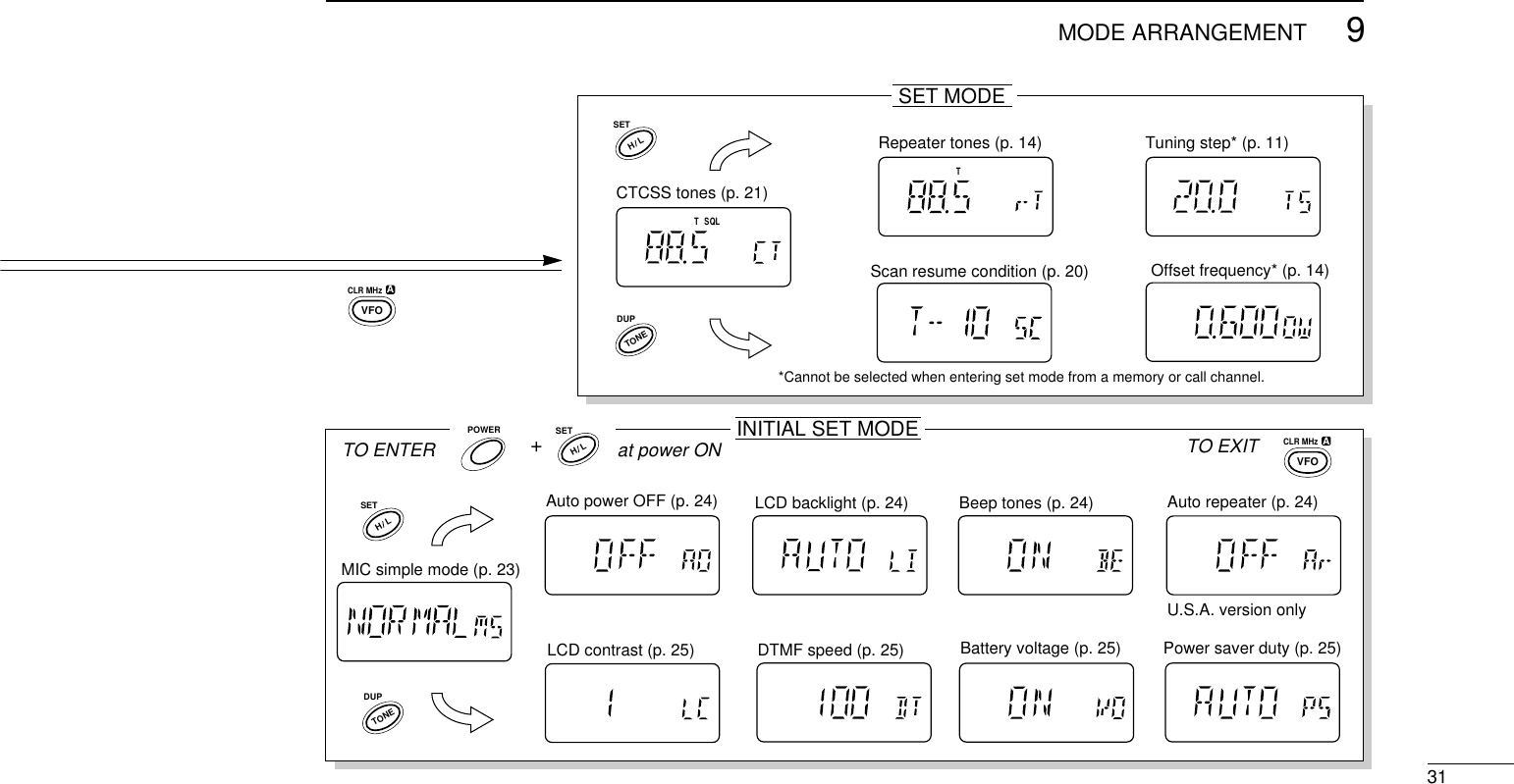
![30MODE ARRANGEMENT9CHANNEL INDICATION MODEVFO MODEMEMORY MODECALL MODEMRDTMF MEMORY MODE+AT POWER ONSee p. 26 for detailspush for 1 sec.push for1 sec.VFOVFOMRMRCALLCALLBANDBANDCLR MHzVFOAPOWERDTMF•MSETSKIPMR.H LBNOTE: Displays for set and initial set modes show the de-fault settings—rotate [DIAL] to change the condition.](https://usermanual.wiki/ICOM-orporated/IC-T7H/User-Guide-15465-Page-34.png)