ICOM orporated IC-T7H Amateur Radio Equipment User Manual IC T7H
ICOM Incorporated Amateur Radio Equipment IC T7H
manual

INSTRUCTION MANUAL
This device complies with Part 15 of the FCC rules. Operation is sub-
ject to the following two conditions: (1) This device may not cause
harmful interference, and (2) this device must accept any interference
received, including interference that may cause undesired operation.
DUAL BAND FM TRANSCEIVER
iT7H

RWARNING! NEVER hold the transceiver so that the
antenna is very close to, or touching exposed parts of the
body, especially the face or eyes, while transmitting. The
transceiver will perform best if the microphone is 5 to 10 cm
(2 to 4 in) away from the lips and the transceiver is vertical.
RWARNING! NEVER operate the transceiver with a
headset or other audio accessories at high volume levels.
Hearing experts advise against continuous high volume op-
eration. If you experience a ringing in your ears, reduce the
volume level or discontinue use.
NEVER connect the transceiver to an AC outlet or to a
power source of more than 16 V DC. Such a connection will
damage the transceiver.
NEVER
connect the transceiver to a power source that is DC
fused at more than 5 A. Accidental reverse connection will be
protected by this fuse, higher fuse values will not give any pro-
tection against such accidents and the transceiver will be ruined.
NEVER attempt to charge alkaline or dry cell batteries. Be-
ware that external DC power connections will charge batteries
inside the battery case. This will damage not only the battery
case but also the transceiver.
i
IMPORTANT
READ ALL INSTRUCTIONS carefully and completely before
using the transceiver.
SAVE THIS INSTRUCTION MANUAL—This instruction man-
ual contains important operating instructions for the IC-T7H.
EXPLICIT DEFINITIONS
The explicit definitions below apply to this instruction manual.
CAUTIONS
WORD DEFINITION
RWARNING Personal injury, fire hazard or electric shock
may occur.
CAUTION Equipment damage may occur.
NOTE If disregarded, inconvenience only. No risk
of personal injury, fire or electric shock.
The IC-T7H complies with essential requirements of the
89/336/EEC directive for Electromagnetic Compatibility.
This compliance is based on conformity with the ETSI
specification ETS300 684 (EMC product standard for
Commercially Available Amateur Radio Equipment).

ii
UNPACKING
Accessories included with the transceiver: Qty.
➀Antenna ............................................................................1
➁Handstrap .........................................................................1
➂Battery pack (BP-173/BP-180) or battery case (BP-170)
attached to the transceiver................................................1
➃Belt clip .............................................................................1
➄Wall charger* ....................................................................1
*Not supplied with battery case versions.
Antenna for U.S.A. version differs from that shown above.
DO NOT push the PTT when not actually desiring to trans-
mit.
DO NOT operate the transceiver near unshielded electrical
blasting caps or in an explosive atmosphere.
AVOID using or placing the transceiver in direct sunlight or
in areas with temperatures below –10°C (+14°F) or above
+60°C (+140°F).
Place unit in a secure place to avoid inadvertent use by chil-
dren.
The use of non-Icom battery packs/chargers may impair
transceiver performance and invalidate the warranty.
Even when the transceiver power is OFF, a slight current still
flows in the circuits. Remove the battery pack or case from
the transceiver when not using it for a long time. Otherwise,
the battery pack or installed dry cell batteries will become ex-
hausted.
For U.S.A. only
CAUTION: Changes or modifications to this device, not ex-
pressly approved by Icom Inc., could void your authority to
operate this device under FCC regulations.
➀➁➂➃
➄

TABLE OF CONTENTS
iii
IMPORTANT ........................................................................ i
EXPLICIT DEFINITIONS ..................................................... i
CAUTIONS .......................................................................... i
UNPACKING ....................................................................... ii
TABLE OF CONTENTS ..................................................... iii
1 PANEL DESCRIPTION ............................................ 1 – 5
■Switches, controls, keys and connectors ................... 1
■Function display ......................................................... 5
2 BATTERY PACKS AND ACCESSORIES ................ 6 – 9
■Battery pack charging ................................................ 6
■Charging precautions ................................................. 6
■About the battery pack ............................................... 6
■Charging connections ................................................ 7
■Battery case ............................................................... 8
■Accessory attachment ................................................ 9
3 BASIC OPERATION ............................................ 10 – 14
■Power ON ................................................................. 10
■Setting a frequency .................................................. 10
■Setting tuning steps .................................................. 11
■Selecting a memory channel .................................... 12
■Lock function ............................................................ 12
■Receive and transmit ................................................ 12
■Repeater operation .................................................. 13
4 ADVANCED FUNCTIONS ................................... 15 – 22
■Memory/call channels .............................................. 15
■DTMF memory operation ......................................... 17
■Scan operation ......................................................... 18
■Subaudible tone operation ....................................... 21
5 OTHER FUNCTIONS ........................................... 23 – 26
■Initial set mode ......................................................... 23
■Channel indication mode .......................................... 26
■CPU resetting ........................................................... 26
6 TROUBLESHOOTING ................................................ 27
7 OPTIONS ..................................................................... 28
8 SPECIFICATIONS ....................................................... 29
9 MODE ARRANGEMENT ..................................... 30 – 31
PANEL DESCRIPTION 1
1
1[PTT]
@[BAND]
A[H/L]
B[TONE]
IJ[DC13.5V]
6[VOL]
9[POWER]
7[RX/TX]
2[LOCK]
8[MONI]
4[SP/MIC]
3
5[DIAL]
C
D
E
F
G
H
K
CLR MHz
SKIP
MW
VFO
MR
CALL
S.MW
A
B
C
D
DTMF•M
.
T SCAN
POWER
SCAN
DUP SET
BAND
TONE
H L
LOCK
MONI
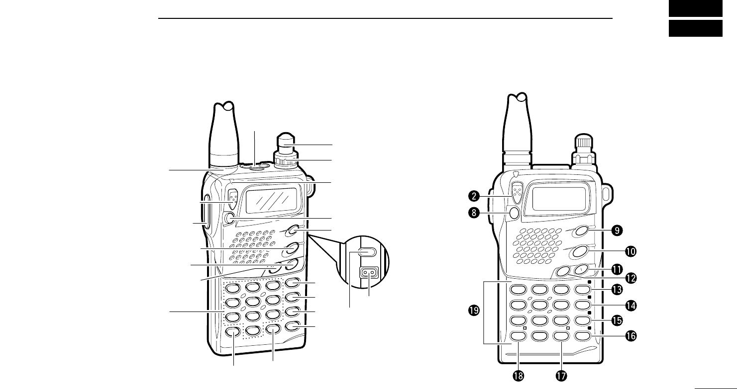
■Switches, controls, keys and connectors
1PANEL DESCRIPTION
2
➏VOLUME CONTROL [VOL]
Rotate [VOL] clockwise to increase volume and counter-
clockwise to decrease volume.
➐RX/TX INDICATOR [RX/TX] (p. 12)
Lights green while receiving a signal or when the squelch is
open; lights red while transmitting.
➑MONITOR SWITCH [MONI] (p. 12)
➥Push and hold this switch to force the squelch
open; release to close it again.
➥Push twice to keep the squelch open; push again
to close it.
➥While pushing this switch, rotate [DIAL] to set the
squelch level.
➥While pushing [PTT], push this switch to transmit
a DTMF memory.
➒POWER SWITCH [POWER]
Push for 1 sec. to toggle power ON and OFF.
• Battery voltage appears for 1 sec. after power ON.
➓BAND SWITCH [BAND/SCAN]
➥Push to toggle between VHF and UHF operation
except in memory mode (p. 10).
➥Push and hold to indicate the selected scan
range (or band) and to start scanning (p. 18).
• While scanning, each push of this switch changes the
selected scan range.
SCAN
BAND
POWER
MONI
➊PTT SWITCH [PTT] (p. 12)
Push and hold to transmit; release to receive.
➋LOCK SWITCH [LOCK]
Slide up to turn the lock function ON.
• [PTT], [VOL], [H/L], [MONI] and [POWER] function even
when the lock function is activated.
➌ANTENNA CONNECTOR (p. 9)
Connects the supplied antenna.
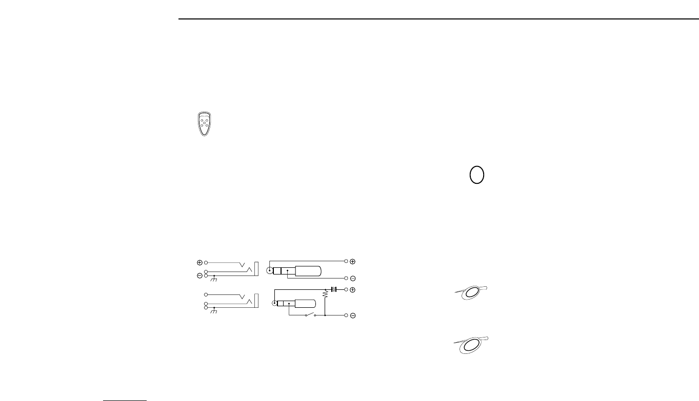
➍EXTERNAL SPEAKER AND MICROPHONE JACKS
[SP/MIC]
Connect an optional speaker-microphone or headset, if de-
sired. The internal microphone and speaker will not func-
tion when either is connected. (See p. 28 for options.)
DExternal connection
➎TUNING DIAL [DIAL]
Rotate [DIAL] to set an operating frequency, select a mem-
ory channel, select set mode contents, change scan direc-
tion, etc.
This connec-
tion does not
apply when a
condensor mi-
crophone is
connected.
Remote Audio out
(8 Ω)
[SP]
MIC
3.5 V
PTT
[MIC] Audio input
PTT
33 kΩ
(2 kΩ)

1
PANEL DESCRIPTION
3
!1 OUTPUT POWER SWITCH [H/L(SET)]
➥Push to toggle between low and high output
power (p. 12).
• “LOW” appears when low output power is selected.
➥Push and hold to enter set mode.
!2 TONE SWITCH [TONE(DUP)]
➥Push this switch to activate the following func-
tions in order (pgs. 21, 22).
• Subaudible tone encoder—“T” appears.
• Pocket beep—“T SQLS” appears.
• Tone squelch—
“T SQL” appears.
• No tone operation—no indicator appears.
➥Push this switch for 1 sec. to select semi-duplex
or simplex operation (p. 13).
• “– DUP” appears during minus duplex operation,
“DUP” appears during plus duplex operation and no
indicator appears during simplex operation.
➥For the European version only, while pushing
[PTT], push this switch to transmit a 1750 Hz
tone burst signal (p. 13).
!3 VFO/CLEAR KEY [VFO(CLR MHz);;]
➥Clears some functions, such as digit input before
entry, scan, etc.
➥Push this key to select VFO mode (p. 10).
➥Push and hold for 1 sec., then rotate [DIAL] to
change the MHz digit (p. 11).
➥While pushing [PTT], this key sends a DTMF “A.”
CLR MHz
VFO
A
DUP
TONE
SET
H L
!4 MEMORY MODE KEY [MR(SKIP)<<]
➥Push this key to select memory mode (p. 12).
•“
XX” appears while in memory mode.
➥While in memory mode, push this key for 1 sec.
to toggle the selected memory channel between
a skip and a non-skip channel (p. 20).
• “SKIP” appears when the channel is set as a skip
channel.
➥While pushing [PTT], this key sends a DTMF “B.”
!5 CALL MODE KEY [CALL==]
➥Push this key to select the call channel (p. 15).
• “C” appears while the call channel is selected.
➥While pushing [PTT], this key sends a DTMF “C.”
!6 SELECT MEMORY WRITE KEY [S.MW(MW)>>]
(pgs. 15, 16)
➥Push this key to enter memory select mode.
•“X” flashes and the [DIAL] can be used for channel
selection (for memory writing or clearing).
➥Push and hold for 1 sec. to write the set contents
into the selected memory channel (or VFO, call
channel).
➥Push then push and hold this key while in mem-
ory select mode to erase the contents of the se-
lected memory channel.
➥While pushing [PTT], this key sends a DTMF “D.”
MW
S.MW
D
CALL
C
SKIP
MR
B

1PANEL DESCRIPTION
4
!7 TONE SCAN KEY [TSCAN?]
➥Push this key for 1 sec. to start and stop tone de-
code scan (p. 13).
• When a subaudible tone is detected, the tone fre-
quency is displayed and overwrites the prepro-
grammed:
➠tone squelch frequency when the
tone squelch
is
in use
;
➠tone encoder (repeater tone) frequency when the
tone squelch
is not in use
.
➥While pushing [PTT], this key sends a DTMF “#.”
!8 DTMF KEY [• (DTMF M@)]
➥Enters a decimal for MHz unit during frequency
input (p. 10).
➥Push and hold for 1 sec. to enter DTMF memory
mode for programming or recall (p. 17).
• To program use [(H/L)SET].
• To transmit use [MONI] while transmitting.
➥While pushing [PTT], this key sends a DTMF “M.”
!9 DIGIT KEYS
➥Input the specified digit during frequency input, memory
channel selection, etc.
➥Transmit the DTMF code of the specified digit while
pushing [PTT].
DTMF•M
.
T SCAN
@0 EXTERNAL DC POWER JACK [DC13.5V]
Allows operation with a 4.5 to 16 V DC power source using
the optional cables, CP-12L or OPC-254L.
CAUTION: Operation with an external DC power
source simultaneously charges batteries inside the bat-
tery case or the battery pack. When using dry cell bat-
teries this may cause battery leakage and damage the
transceiver; when using a Ni-Cd battery pack this may
cause battery overcharging and shorten the life of the
battery pack.
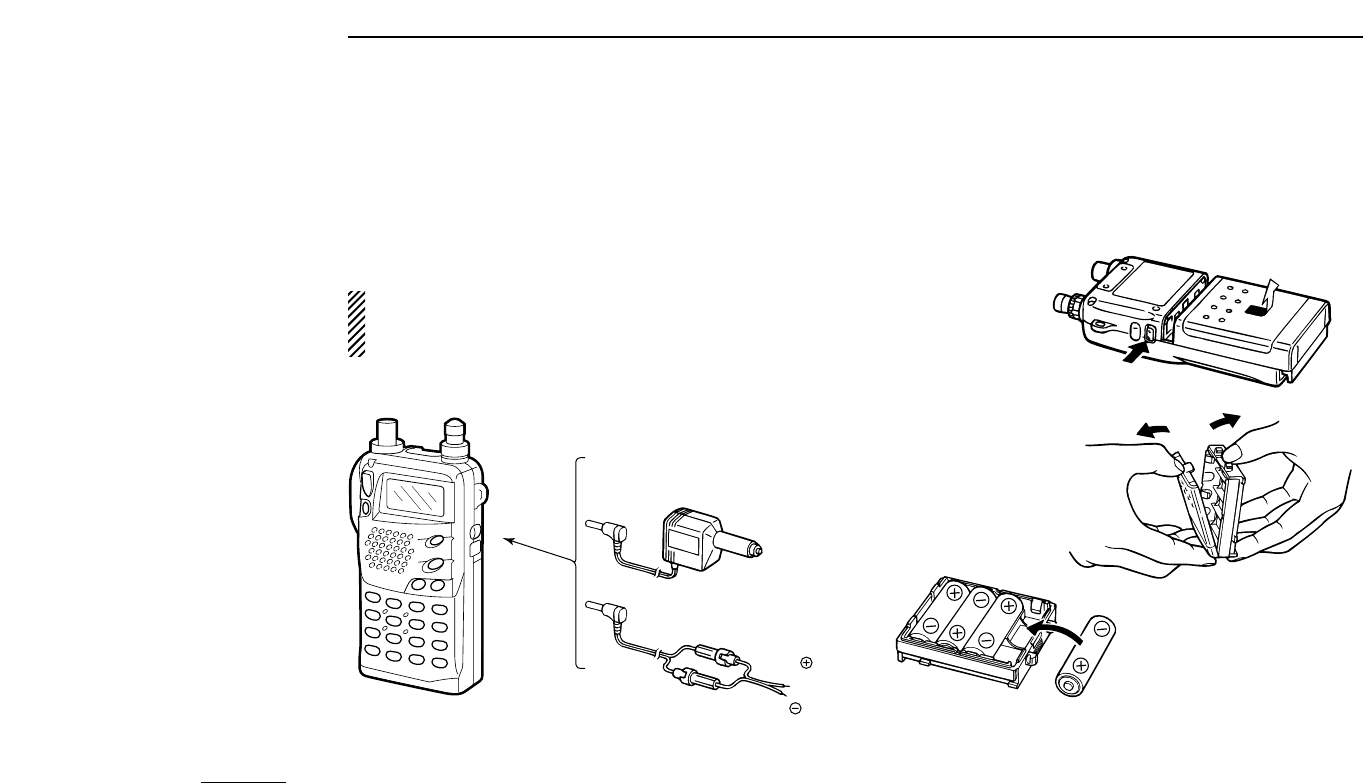
@1 BATTERY PACK RELEASE (p. 8)
Push to open the latch for battery pack removal.
5
1
PANEL DESCRIPTION
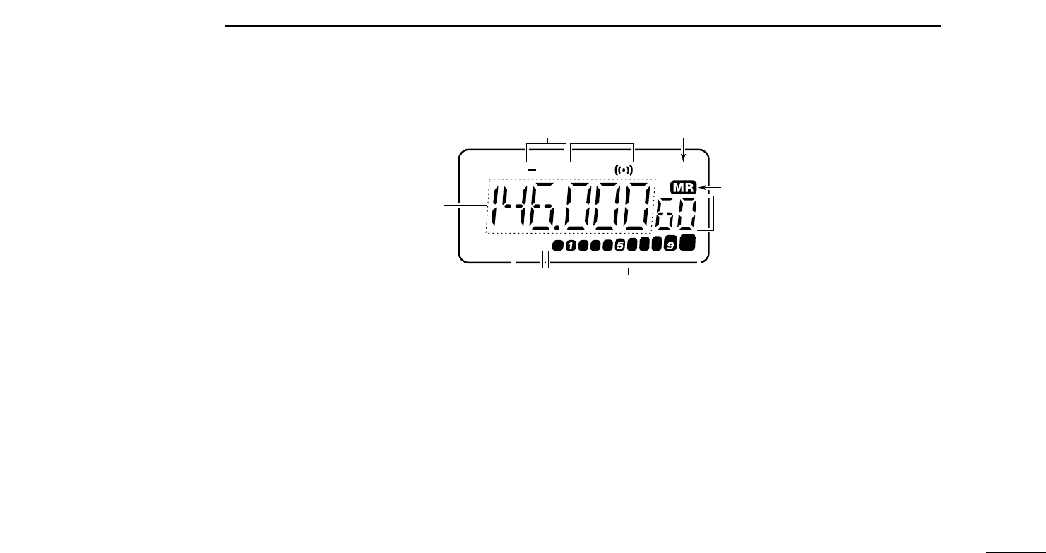
➎MEMORY CHANNEL INDICATOR (p. 12)
Indicates the selected memory channel and other items
such as the call channel, key lock indicator, etc.
➏S/RF INDICATORS (p. 12)
Show the relative signal strength while receiving.
and the output power selection while transmitting.
➐LOW POWER INDICATOR (p. 12)
Appears when low output power is selected.
➑ALPHANUMERIC READOUTS
Show the selected frequency, set mode contents, etc.
D
LOW
UP T SQL SKIP
➊➋ ➌
➍
➎
➏
➐
➑
■Function display
➊DUPLEX INDICATORS (p. 13)
Appear during semi-duplex operation.
• “– DUP” appears for minus duplex; “DUP” only appears for plus
duplex.
➋TONE INDICATORS (p. 21)
“T” appears when the subaudible tone encoder is in use,
“T SQLS” appears during pocket beep operation and
“T SQL” appears when the tone squelch function is acti-
vated.
➌SKIP INDICATOR (p. 20)
Appears when a selected memory channel is set as a skip
channel.
➍MEMORY MODE INDICATOR (p. 15)
Appears while in memory mode.

6
BATTERY PACKS AND ACCESSORIES
2
■Battery pack charging
The supplied* BP-180
BATTERY PACK
includes rechargeable
Ni-Cd batteries and can be charged approx. 300 times.
Charge the battery pack before first operating the transceiver
or when the battery pack becomes exhausted.
*Optional for versions which come with the BP-170
BATTERY CASE
.
If you want to be able to charge the battery pack more than
300 times, the following points should be observed:
1. Avoid overcharging. The charging period should be less
than 48 hours.
2. Use the battery until it becomes almost completely ex-
hausted under normal conditions. We recommend battery
charging just after transmitting becomes impossible.
■Charging precautions
NEVER attempt to charge dry cell batteries. This will cause
internal liquid leakage and damage the battery case and
transceiver.
NEVER connect two or more chargers at the same time.
Charging may not occur under temperatures of 10°C (50°F)
or over temperatures of 40°C (104°F).
■About the battery pack
DOperating period
Depending on the attached battery pack, the operating period
of the transceiver varies. Refer to p. 28 for battery pack spec-
ifications.
DBattery pack life
If your battery pack seems to have no capacity even after
being fully charged, completely discharge it by leaving the
power ON overnight. Then, fully charge the battery pack
again.
If the battery pack still does not retain a charge (or very little),
a new battery pack must be purchased.
Recycling information
(U.S.A. only)
The product that you purchased contains a
rechargeable battery. The battery is recyclable. At
the end of its useful life, under various state and
local laws, it may be illegal to dispose of this battery into the
municipal waste stream. Call 1-800-8-BATTERY for battery
recycling options in your area or contact your dealer.
RBRC
RBRC
Ni-
Cd
7
2
BATTERY PACKS AND ACCESSORIES
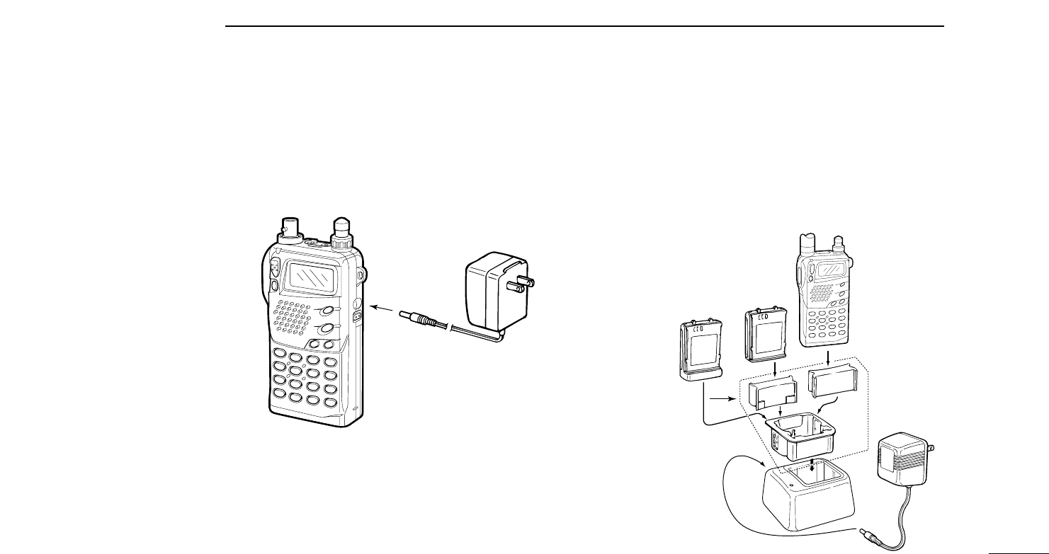
■Charging connections
DRegular charging
Attach the supplied* or optional battery pack; then, connect
the supplied* wall charger via an AC outlet as shown below.
*Optional for versions which include a battery case.
DRapid charging with the BC-119
➀Insert the AD-56A into the charging slot of the BC-119.
➁Insert the AD-56B into the groove in the AD-56A (front-fac-
ing side of the AD-56A).
➂Insert the battery pack, either by itself or attached to the
transceiver, into the AD-56B.
To [DC13.5V]
Wall charger
BP-171 or
BP-172
attached to
the transceiver
Check orientation
for correct
charging
BP-171 or
BP-172
WITHOUT
transceiver
BP-173 or
BP-180
WITH
or WITHOUT
transceiver
AD-56
(optional)
BC-119
(optional)
Charging periods:
1 hour (w/BP-171
or BP-180)
1.5 hours (w/BP-172 or BP-173)
Charging periods:
15 hours (w/BP-171, BP-173 or BP-180)
20 hours (w/BP-172)
8
2BATTERY PACKS AND ACCESSORIES
DOperation with an optional cable
Connect an optional charger or cable to the transceiver as il-
lustrated below. Be careful of battery overcharging as the con-
nected battery is charged simultaneously.
■Battery case
When using a battery case attached to the transceiver, install
4 AA(R6) size alkaline batteries as illustrated below.
CAUTION: Remove dry cell batteries when the BP-170
BATTERY CASE
is connected, otherwise the battery may
leak and damage the transceiver.
Open the case.
Remove the case
from the transceiver.
Install 4 AA(R6) size dry
cell batteries into the
battery case.
CP-12L
(optional)
OPC-254L
(optional)
To a cigarette
lighter socket
To a 4.5 to 16* V DC
power source
To
[DC13.5V]
white
black
*To charge the battery pack
12 to 16 V DC is necessary.
9
2
BATTERY PACKS AND ACCESSORIES
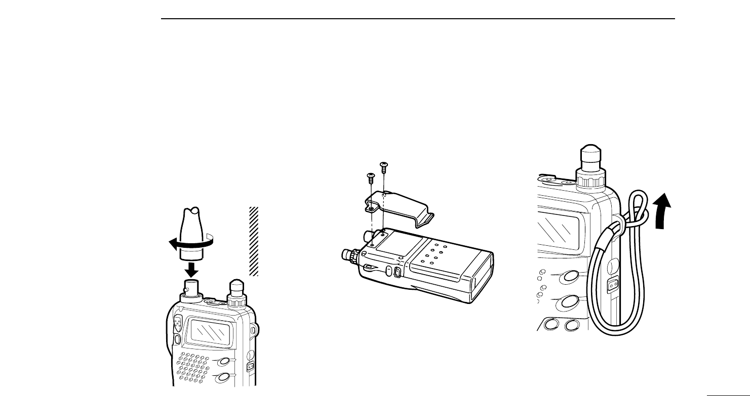
DAntenna
Insert the supplied antenna into the an-
tenna connector and rotate the antenna
as shown in the diagram below.
Keep the jack cover attached when
jacks are not in use to avoid bad con-
tacts.
DBelt clip
Remove screws, then attach the belt clip
using the same screws. Conveniently at-
taches to your belt.
DHandstrap
Attach the handstrap as shown in the di-
agram below. Facilitates carrying.
■Accessory attachment
CAUTION:
Transmitting
without the
antenna may
damage the
transceiver.
10
3BASIC OPERATION
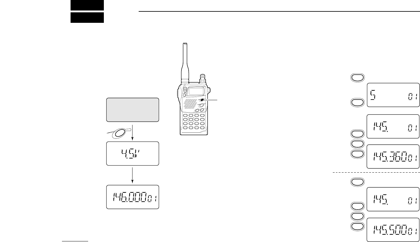
■Power ON
Push and hold [POWER]
for 1 sec. to turn power
ON.
• Current battery voltage is
displayed for 2 sec.
• The display shows the approx. volt-
age in 0.5 V steps.
• When the battery voltage is lower
than 4.5 V, “LOW V” appears. Charge
the battery in this case.
• If “OVER V” appears, UNPLUG the
external DC plug immediately. Con-
nected voltage is over 16 V and could
damage the transceiver.
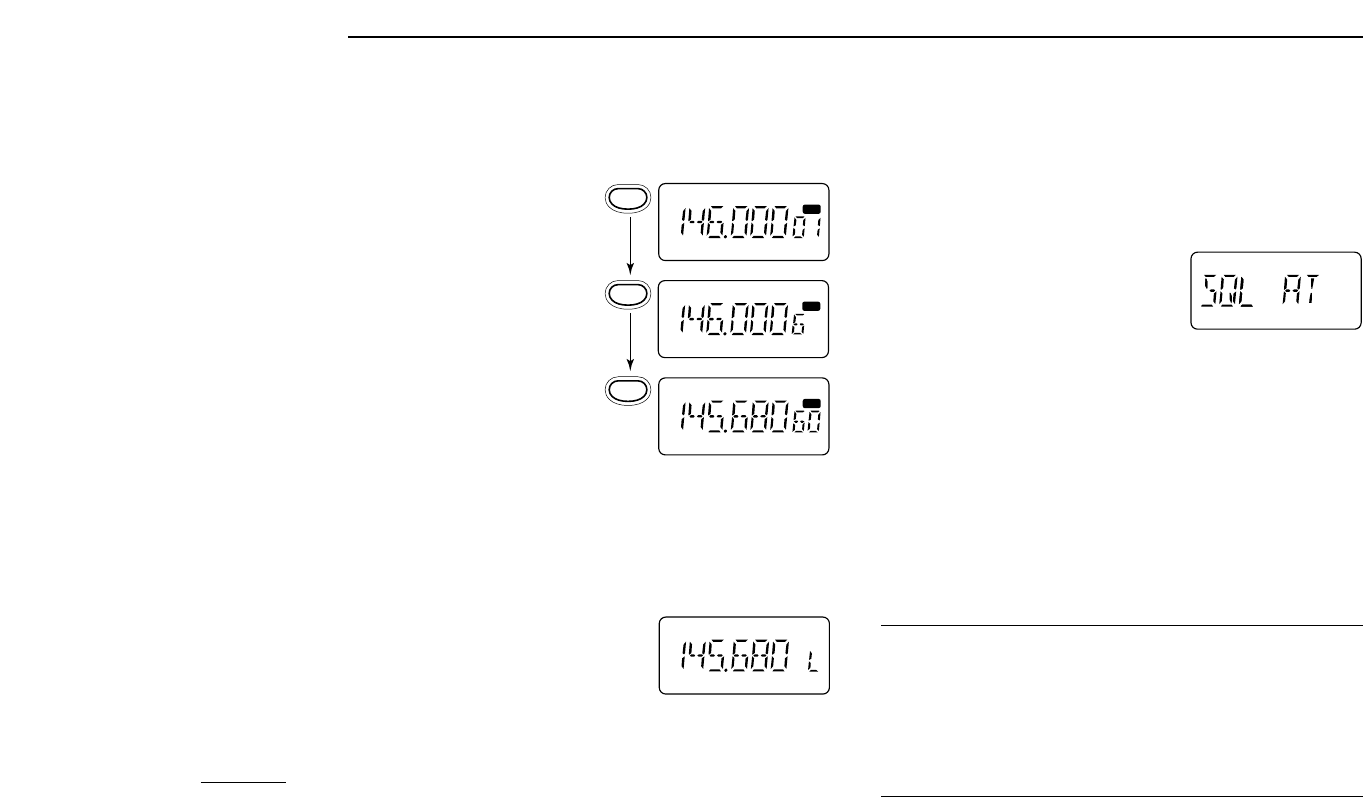
■Setting a frequency
DVia the keypad
(within a band)
➀Push [VFO] to select VFO
mode.
➁Push [BAND] to select the
VHF or UHF band.
➂Push 4 digit keys, starting
from the 1 MHz digit and in-
cluding the decimal point [•],
to input a frequency.
• When a digit is mistakenly
input, push [VFO] and input
from the beginning.
• “0,” “2,” “5” and “7” are accept-
able for the 1 kHz digits (de-
pending on the 10 kHz digit).
➃To change the frequency
from the 100 kHz digit, push
[•], then 3 digits.
for 1 sec.
after 2 sec.
POWER
3
6
5
5
0
0
0
.
.
Push for
1 sec.
3
BASIC OPERATION
11
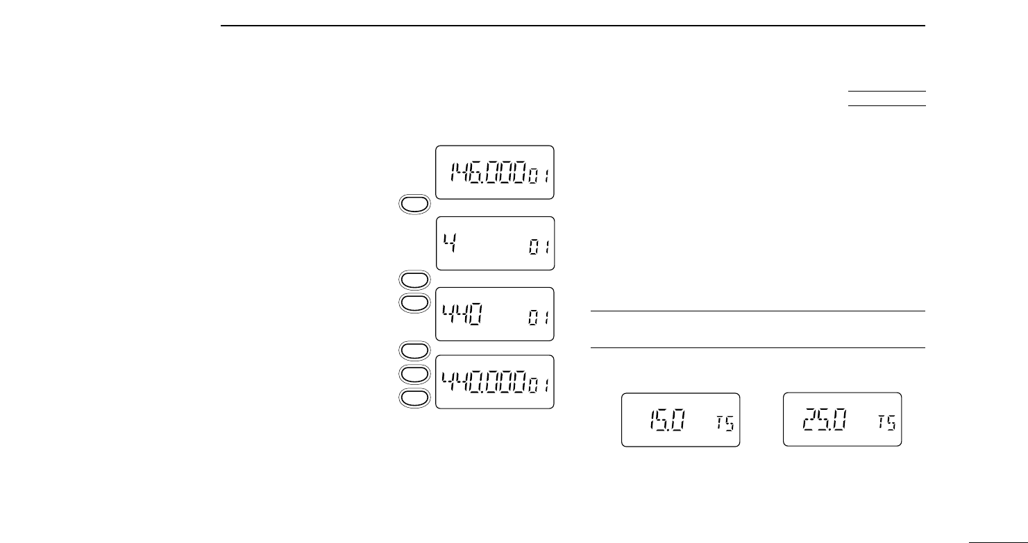
■
Setting tuning steps
This transceiver has 8 tuning steps (VHF and UHF bands
have independent settings) as follows:
• 5 kHz • 10 kHz • 12.5 kHz • 15 kHz
• 20 kHz • 25 kHz • 30 kHz • 50 kHz
➀Push [VFO] to select VFO mode.
➁Push [BAND] to select the VHF or UHF band.
➂Push [(H/L)SET] for 1 sec. to enter set mode.
➃Push [TONE] or [H/L] several times until “TS” appears.
➄Rotate [DIAL] to select the desired tuning step.
➅Push [(VFO)CLR] to exit set mode.
For convenience, select a tuning step that matches the fre-
quency intervals of repeaters in your area.
[DISPLAY EXAMPLE]
15 kHz tuning step 25 kHz tuning step
USING
SET MODE
DVia the keypad
(other band directly)
➀Push [VFO] to select VFO
mode.
➁Push 6 digit keys, starting
from the 100 MHz digit.
• The operating band changes
automatically.
• It’s not necessary to input the
decimal point.
DOther methods
➥
VIA THE DIAL:
Rotate [DIAL] to change the frequency ac-
cording to the set tuning steps.
➥
USING THE MHz STEP:
Push [(VFO)MHz] for 1 sec., then
rotate [DIAL] to change the frequency in one MHz steps.
0
0
0
0
4
4
■
Receive and transmit
➀Push [POWER] for 1 sec. to turn power ON.
➁Adjust the [VOL] control to the desired level.
• While pushing [MONI], rotate [VOL].
➂Set the squelch level.
• While pushing [MONI], rotate [DIAL].
• 4 selections are available, “OP”
(open), “AT” (automatic), 1 and 2.
➃Set an operating band and frequency.
When a signal is received:
➥Squelch opens and audio is emitted from the speaker.
➥The S/RF indicator shows the relative signal strength.
➄Push [H/L] to toggle output power between high and low.
• “LOW” appears when low output power is selected.
➅Push and hold [PTT] to transmit; then speak into the mic.
•Do not hold the microphone too close to your mouth or speak
too loudly. This may distort the signal.
• The TX/RX indicator lights red.
• The S/RF indicator shows the output power selection.
➆Release [PTT] to return to receive.
✔
CONVENIENT
Monitor function:
Push and hold [MONI] to listen to weak
signals that do not open the squelch; or push [MONI] twice to
monitor a signal without having to continuously hold [MONI].
Squelch control:
The transceiver employs a
noise pulse
count system
and therefore, squelch is adjusted automati-
cally, when “AT” is selected.
12
3BASIC OPERATION
■Selecting a memory channel
➀Push [MR] to select memory
mode.
➁Push 2 digit keys to select
the desired memory channel
(or rotate [DIAL]).
• The first nine memory chan-
nels are preceded by a “0.”
• To select scan edges 1A to 4B,
use [@] for “A” and [?] for “B.”
• Only programmed memory
channels can be selected.
■Lock function
The lock function prevents accidental frequency changes and
accidental function activation.
➥Slide [LOCK] up or down to set the
lock function ON or OFF, respec-
tively.
• “L” appears while the lock function is
activated.
• [PTT], [POWER], [VOL], [MONI], and
[H/L] can be used regardless of this setting.
MR
MR
MR
MR
6
0

3
BASIC OPERATION
13
■Repeater operation
DGeneral
When using a repeater, the transmit frequency is shifted from
the receive frequency by the offset frequency. It is convenient
to program repeater information into memory channels
(p. 15).
➀Set the operating band and receive frequency (repeater
output frequency).
➁Push [(TONE)DUP] for 1 sec. once to select – DUP or twice
to select DUP.
• “– DUP” or “DUP” appears to indicate the transmit frequency for
minus shift or plus shift, respectively.
• When the auto repeater function is in use (U.S.A. version only)
this selection and step ➂are not necessary (p. 24).
➂Push [TONE] to activate the subaudible tone encoder, ac-
cording to repeater requirements.
• “T” appears.
• Refer to the table of tone frequencies on the following page.
➃Push and hold [PTT] to transmit.
• The displayed frequency automatically changes to the transmit
frequency (repeater input frequency).
• If “OFF” appears, check the offset frequency (p. 14).
➄Release [PTT] to receive.
➅Push and hold [MONI] to check whether the other station’s
transmit signal can be directly received or not.
DTone information
Some repeaters require a tone to be accessed. In this case,
precede step ➃at left with the required tone.
DTMF TONES (U.S.A. and Asia versions only)
While pushing [PTT], push the desired digit key(s) to transmit
DTMF tones
• The transceiver has 9 DTMF memory channels. See p. 17 for de-
tails.
1750 Hz TONE (Europe and Italy versions only)
While pushing [PTT], push and hold [TONE] for 1 to 2 sec. to
transmit a 1750 Hz tone signal.
✔
CONVENIENT
Tone scan function:
When you don’t know the subaudible
tone used for a repeater, the tone scan is convenient for de-
tecting the tone frequency.
Push and hold [T SCAN?] to activate. See p. 22 for more in-
formation.
3BASIC OPERATION
14
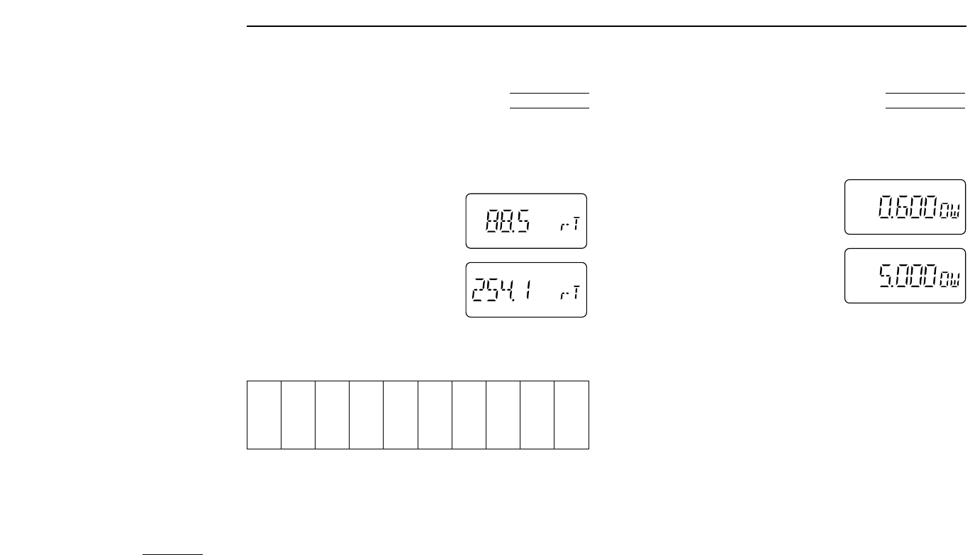
DSetting subaudible tones for
repeater use
Some repeaters require subaudible tones to be accessed.
Subaudible tones are superimposed over your normal signal
and must be set in advance.
➀
Push [VFO] to select VFO mode.
➁
Push [BAND] to select VHF or UHF.
➂Push [(H/L)SET] for 1 sec. to enter
set mode.
➃Push [TONE] or [H/L] several times
until “rT” appears.
➄Rotate [DIAL] to select the desired
subaudible tone.
➅Push [(VFO)CLR] to exit set mode.
•Available subaudible tone frequencies (unit: Hz)
T
T
67.0 79.7 94.8 110.9 131.8 156.7 171.3 186.2 203.5 229.1
69.3 82.5 97.4 114.8 136.5 159.8 173.8 189.9 206.5 233.6
71.9 85.4 100.0 118.8 141.3 162.2 177.3 192.8 210.7 241.8
74.4 88.5 103.5 123.0 146.2 165.5 179.9 196.6 218.1 250.3
77.0 91.5 107.2 127.3 151.4 167.9 183.5 199.5 225.7 254.1
USING
SET MODE
DSetting an offset frequency
When communicating through a repeater, the transmit fre-
quency is shifted from the receive frequency by an amount
determined by the offset frequency.
➀
Push [VFO] to select VFO mode.
➁
Push [BAND] to select VHF or UHF.
➂Push [(H/L)SET] for 1 sec. to enter
set mode.
➃Push [TONE] or [H/L] several times
until “OW” appears.
➄Rotate [DIAL] to select the desired
offset.
• Selectable steps are the same as the
pre-set tuning steps.
• MHz step may be helpful for large frequency changes—push
[(VFO)MHz] for 1 sec.
➅Push [(VFO)MHz] to exit set mode.
■
Auto low power
When transmitting for 6 continuous min. at high power, the
IC-T7H automatically selects low power. This function cannot
be turned OFF and activates when the power supply is at ap-
prox. 11 V or more. To return to high power on transmit, select
receive, then switch back to transmit.
DUP
DUP
USING
SET MODE

ADVANCED FUNCTIONS 4
15
DProgramming during selection
➀Push [VFO] to select VFO mode.
➁Set the desired frequency:
➥Set other data, such as re-
peater information, etc. using
set mode if required.
➂Push [S.MW] momentarily.
•“X” flashes.
• Do not hold [S.MW] for more than 1
sec., otherwise the memory channel
will overwrite the displayed number.
➃Rotate [DIAL] to select the desired
channel.
• Call channel and scan edge channels,
as well as regular memory channels,
can be programmed in this way.
• If you want to confirm the VFO fre-
quency, push [S.MW] momentarily.
➄Push [S.MW] for 1 sec. to program.
•“X” stops flashing.
D
LOW
UP
D
LOW
UP
D
LOW
UP
D
LOW
UP
MR
MR
■
Memory/call channels
The transceiver has 70 memory channels (60 regular, 4 pairs
of scan edge channels for mixed bands and 1 call channel for
each band). Note that memory channels are not grouped ac-
cording to band. In other words, a given memory channel can
be programmed with either a VHF frequency or a UHF fre-
quency. This is not the case with call channels. Call channels
are band specific.
The following can be programmed into memory/call channels:
• Operating frequency
• Duplex direction with an offset frequency (pgs. 13, 14)
• Subaudible tone encoder or tone squelch ON/OFF with a
tone (CTCSS) frequency (pgs. 21, 22)
• Skip information (p. 20)
4ADVANCED FUNCTIONS
16
DProgramming after selection
➀Select the memory channel to be programmed:
➥Push [MR] to select memory mode.
➥Rotate [DIAL] (or use the keypad) to select the memory
channel.
• Non-programmed channels cannot be selected.
➁Set the desired frequency in VFO mode:
➥Push [VFO] to select VFO mode.
➥Set the desired frequency using the keypad or [DIAL].
➥Set other data, if desired.
➂Push [S.MW] for 1 sec. to program.
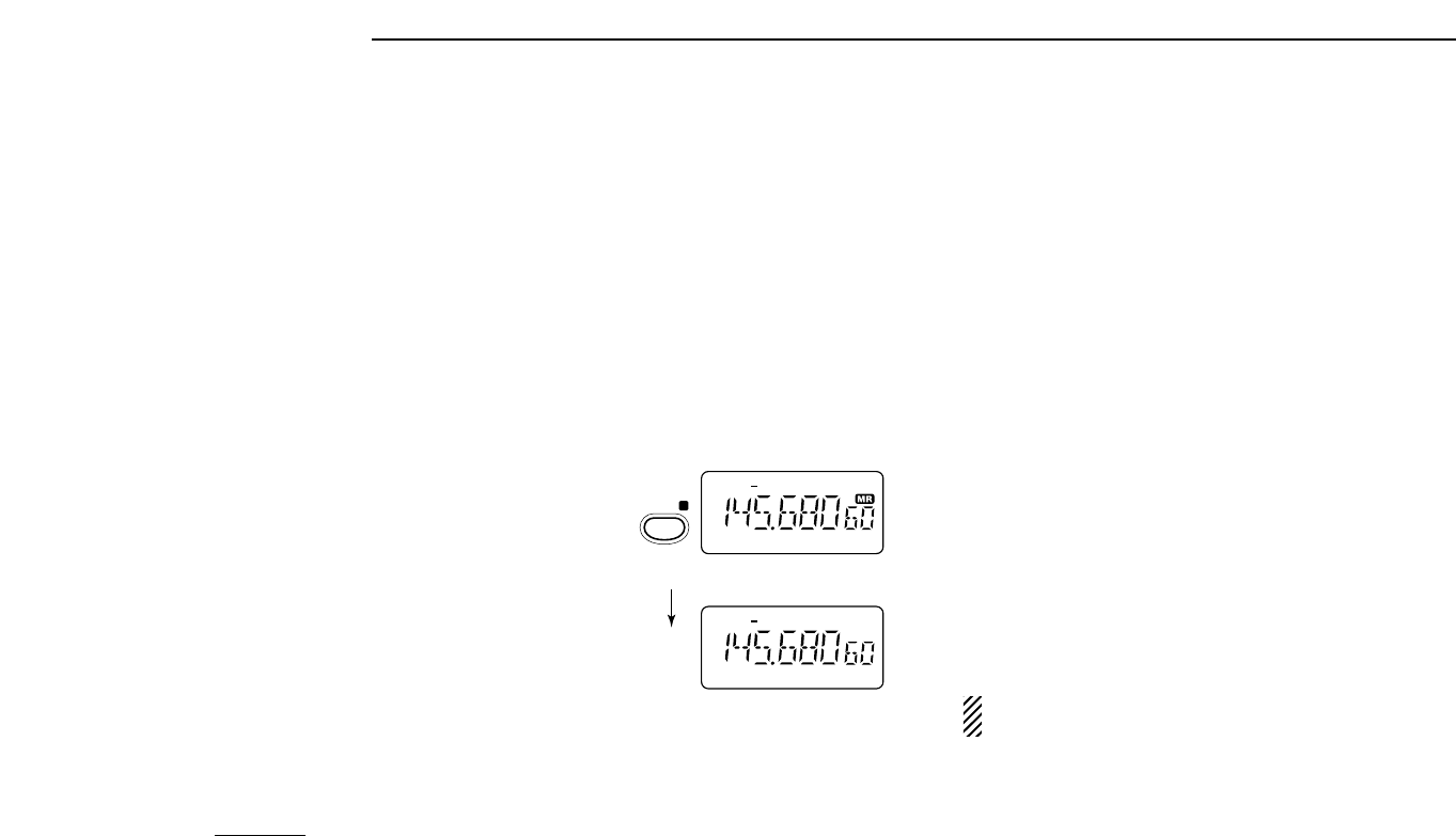
DMemory/call ➾VFO
➀Select the memory/call
channel to be transferred:
➥Push [MR] (or [CALL])
to select memory (call)
mode.
➥Rotate [DIAL] (or use
the keypad) to select the
memory channel.
➁Push [S.MW] for 1 sec. to
transfer to VFO.
DMemory/call ➾call/memory
➀Select the memory/call channel to be transferred:
➥Push [MR] (or [CALL]) to select memory (call) mode.
➥Rotate [DIAL] (or use the keypad) to select the memory
channel.
➁Push [S.MW] momentarily.
• A beep sounds, “VF” appears and “X” flashes.
• Do not hold [S.MW] for more than 1 sec., otherwise the memory
channel will overwrite the VFO.
➂Rotate [DIAL] to select a memory or call channel to transfer
the data.
➃Push [S.MW] for 1 sec. to program.
•“X” stops flashing.
DMemory clear
➀Push [S.MW] momentarily.
➁Select the memory channel to be cleared with [DIAL].
➂Push [S.MW] briefly, then a second time for 1 sec.
• 3 beeps sound, then the frequency is cleared.
•“X” flashes continuously.
• Scan edges 1A and 1B and call channels cannot be cleared.
➃Push [(VFO)CLR] to stop the flashing.
NOTE: Be careful — the contents of cleared memories
CANNOT be recalled.
DUP
DUP
VFO mode selected
for
1 sec. Memory mode
MW
S.MW
D
4
ADVANCED FUNCTIONS
17
DTransmitting a DTMF code
➀Select the DTMF channel to be transmitted:
➥
Push
[(•)DTMF] for 1 sec.
to select DTMF memory mode.
➥Rotate [DIAL] to select the desired DTMF channel.
➁While pushing [PTT] push [MONI] to transmit the selected
DTMF channel’s contents.
DDTMF transmit speed
When slow DTMF transmission speeds are required (such as
for some repeaters) the transceiver’s rate of DTMF transmis-
sion can be adjusted. See p. 25 for details.
■
DTMF memory operation
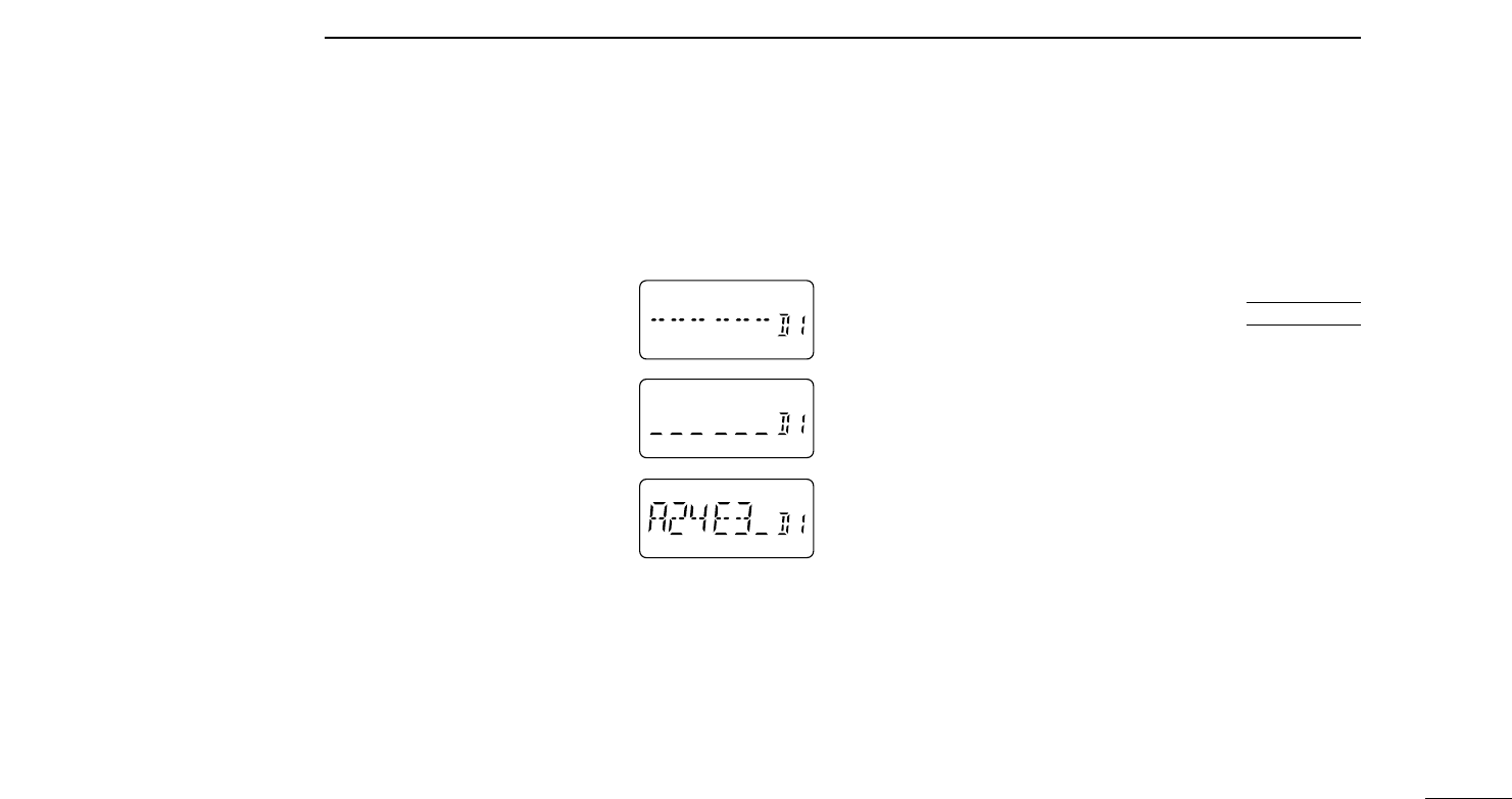
DProgramming a DTMF code
The transceiver has 9 DTMF memory channels (D1 to D9) for
storage of often-used DTMF codes of up to 16 digits.
➀Push [(•)DTMF] for 1 sec. to enter
DTMF memory mode.
➁Rotate [DIAL] to select the desired
channel.
➂Push [(H/L)SET] for 1 sec. to enter
DTMF programming mode.
• “_ _ _ _ _ _” appears.
• Programmed memories can be
cleared in this way.
➃Push digit keys to enter the de-
sired DTMF code.
• A maximum of 16 digits can be input.
• If a digit is mistakenly input, push
[H/L] then repeat from step ➂.
➄Push [(H/L)SET] to input the digits.
• A beep sounds.
➅Push [VFO] or [MONI] to exit DTMF programming mode.
• When pushing [MONI], the programmed contents can be moni-
tored.
AT
POWER ON
■Scan operation
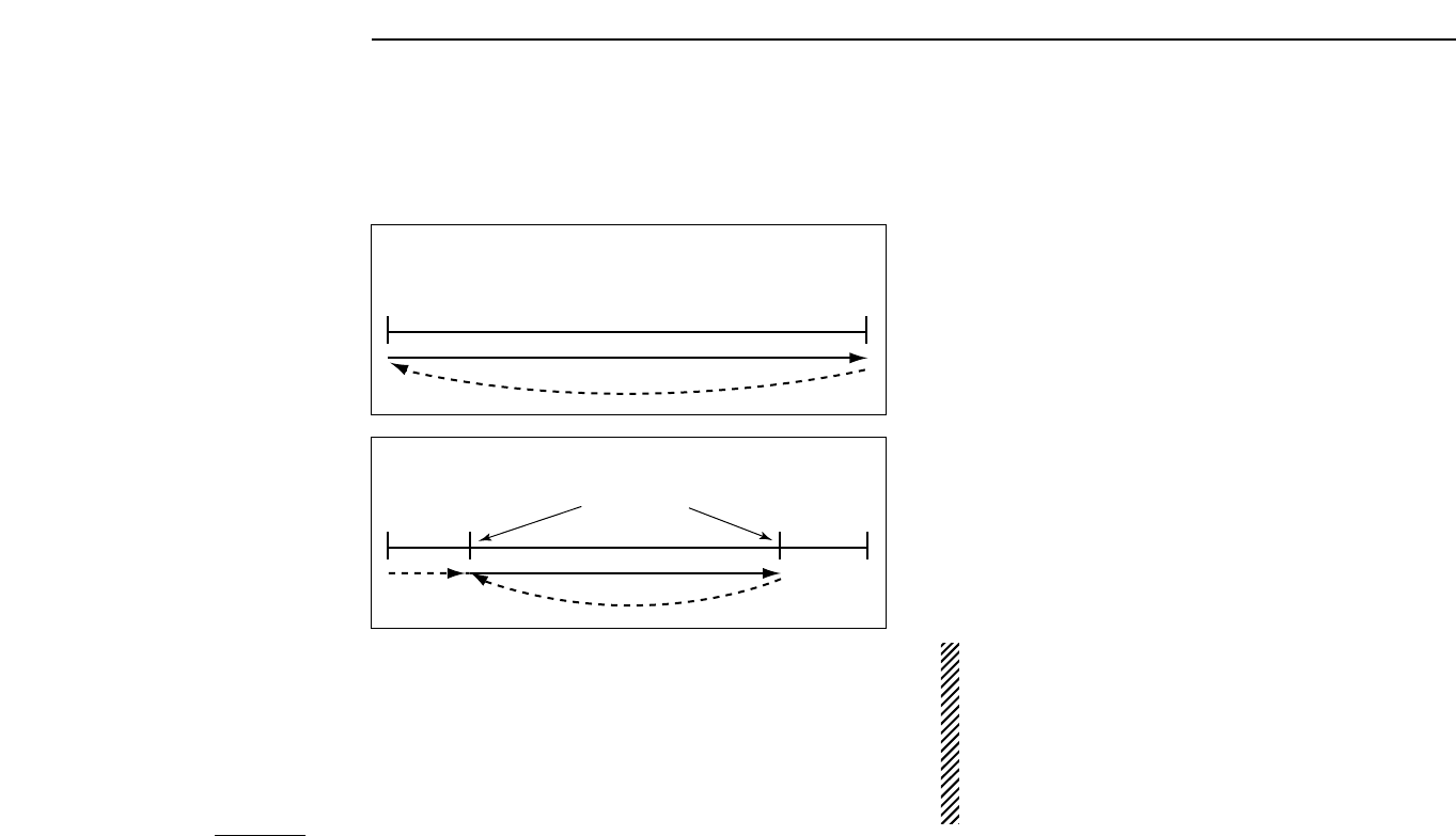
DFull/programmed scan
FULL SCAN:
Repeatedly scans all frequencies over an entire
band (the 144 MHz band or the 430(440) MHz band).
PROGRAMMED SCAN:
Repeatedly scans between two
user-programmed frequencies. Used for checking for fre-
quencies within a specified range such as repeater output fre-
quencies, etc. Four pairs of scan edges are available.
4ADVANCED FUNCTIONS
18
➀Push [VFO] to select VFO mode.
➁Push [(BAND)SCAN] for 1 sec.; then, while continuing to
push [(BAND)SCAN], rotate the tuning dial to select the de-
sired scan range.
➥The following scan ranges are selectable:
• “ALL 144” for full scan on the 144 MHz band.
• “ALL 430” or “ALL 440” for full scan on the 430(440) MHz
band.
• “PROG 1” to “PROG 4” for one of the programmed scans.
➥After releasing [(BAND)SCAN] the selected scan starts.
➥To activate the previously selected scan, dial rotation is
not necessary—just push [(BAND)SCAN] for 1 sec.
➥During scan, the following can be changed:
• Scan range using [(BAND)SCAN], with/without [DIAL].
• Scan direction using [DIAL].
➂To stop the scan, push [(VFO)CLR].
NOTE: For programmed scan, scan edges must be pro-
grammed in advance (1A/1B are programmed by default).
Program scan edges in the same manner as regular mem-
ory channels (p. 15)
If the same frequencies are programmed into a pair of
scan edges, programmed scan edge flashes, such as
“P1,” but programmed scan does not proceed.
FULL SCAN
PROGRAMMED SCAN
Band
edge (e.g. 144.00) Band
(e.g. 148.00) edge
Scan
Jump
Band
edge Band
edge
Scan
Jump
Scan edges
4
ADVANCED FUNCTIONS
19
➀Push [MR] to select memory mode.
➁While pushing [(BAND)SCAN] rotate the tuning dial to se-
lect the desired band.
➥The following scan bands are selectable:
• “SEL ALL” for all channel scan.
• “SEL 144” for selected band scan of the 144 MHz band.
• “SEL 430” or “SEL 440” for selected band scan of the
430(440) MHz band, depending on version.
➥After releasing [(BAND)SCAN], the selected scan starts.
➥To activate the previously selected scan, dial rotation is
not necessary—just push [(BAND)SCAN] for 1 sec.
➥During scan, the following can be changed:
• Scan range using [(BAND)SCAN], with/without [DIAL].
• Scan direction using [DIAL].
➂To stop the scan, push [(VFO)CLR].
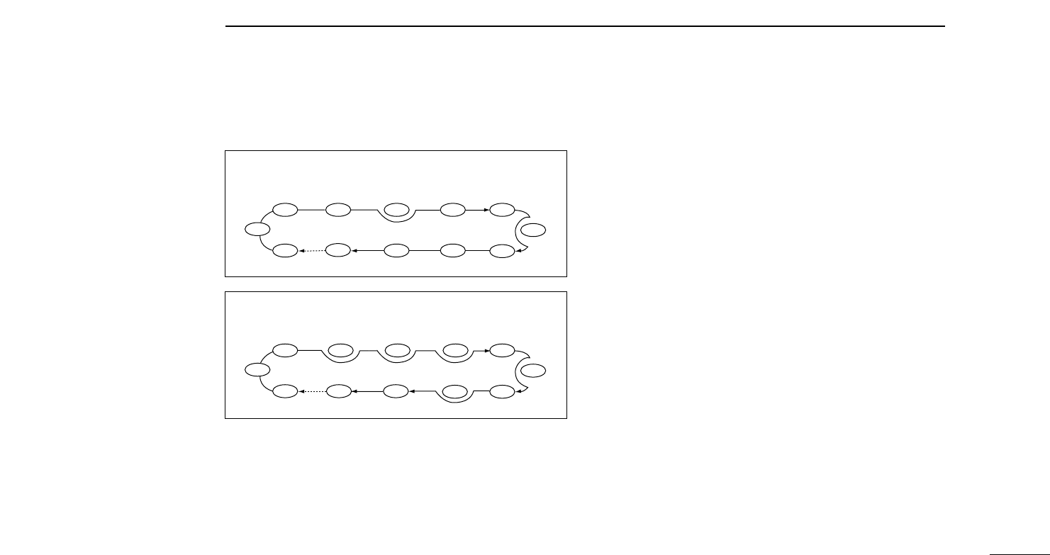
DMemory (skip) scan
ALL CHANNEL SCAN:
Repeatedly scans all programmed
memories, except for those set as skip channels.
BAND SELECT SCAN:
Repeatedly scans all memories with
programmed frequencies in the 144 MHz band or 430(440)
MHz band, except for those set as skip channels.
ALL CHANNEL SCAN
BAND SELECT SCAN (Example: 144 MHz band)
Not yet
programmed
SKIP
Mch 1 Mch 7
Mch 2 Mch 3 Mch 4
UHFUHF VHF
VHFVHFVHFVHF
VHF
VHF
UHF
Mch 5 Mch 6
Mch 8
Mch 9
Mch 60 Mch 11 Mch 10
Not yet
programmed
SKIP
Mch 1 Mch 7
Mch 2 Mch 4Mch 3 Mch 5 Mch 6
Mch 8
Mch 60 Mch 11 Mch 10 Mch 9
4ADVANCED FUNCTIONS
20
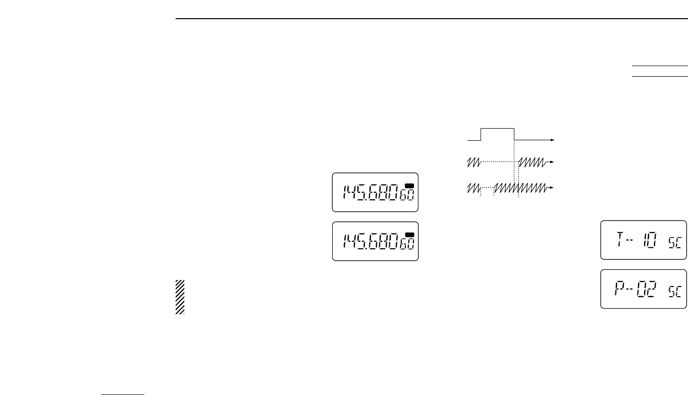
DScan resume condition
The resume condition can be selected as a pause or timer
scan. This setting is common for all scans.
When receiving a signal, pause
scan pauses until the signal
disappears; timer scans pauses
for 10 sec.
➀Push [(H/L)SET] for 1 sec. to enter
set mode.
➁Push [H/L] or [TONE] one or more
times until “SC” appears.
➂Rotate [DIAL] to select the desired
scan resume condition.
• “T-10”: scan pauses for 10 sec. on a
received signal.
• “P-02”: scan pauses on a received signal until it disappears.
➃Push [(VFO)CLR] to exit set mode.
DSetting a skip channel
Memory channels can be set to be skipped during memory
scan. This is useful to speedup the memory scan interval.
➀Select the memory channel to be programmed as a skip
channel:
➥Push [MR] to select memory mode.
➥Rotate [DIAL] (or use the keypad) to select a memory
channel.
➁Push [(MR)SKIP] for 1 sec. to set
the memory channel as a skip
channel.
• “SKIP” appears.
➂Repeat step ➁to cancel a skip
channel.
• “SKIP” disappears.
R
USING
SET MODE
MR
SKIP
MR
NOTE: Scan edge channels, 1A to 4B, cannot be set to
show “SKIP” settings, however, they will be skipped dur-
ing memory scan.
Pause
scan
Receiving
a signal
Timer
scan
10 sec. 2 sec.

4
ADVANCED FUNCTIONS
21
DSetting subaudible tones for
tone squelch operation (CTCSS tones)
Separate tone frequencies can be set for tone squelch oper-
ation than for repeater operation (the same range of tones is
available—see below). Like repeater tones, these are set in
set mode.
➀Select VFO or a memory channel.
➁Push [(H/L)SET] for 1 sec. to enter
set mode.
➂Push [TONE] or [H/L] one or more
times until “CT” appears.
➃Rotate [DIAL] to select the desired
subaudible tone.
➄Push [(VFO)CLR] to exit set mode.
•Available subaudible tone frequencies (unit: Hz)
■Subaudible tone operation
DTone squelch operation
The tone squelch opens only when receiving a signal con-
taining a matching subaudible tone. You can silently wait for
calls from group members using the same tone.
➀Set the operating frequency.
➁Set the desired subaudible tone in set mode.
• See right for programming.
➂Push [TONE] one or more times until “TSQL” appears.
➃When the received signal includes a matching tone,
squelch opens and the signal can be heard.
• When the received signal’s tone does not match, tone squelch
does not open, however, the S-indicator shows signal strength.
• To open the squelch manually, push and hold [MONI].
➄Operate the transceiver in the normal way.
➅To cancel the tone squelch, push [TONE].
✔
CONVENIENT
Store subaudible tone frequencies and tone squelch ON/OFF
settings in memories (call) for easy recall.
T
T
SQL
SQL
USING
SET MODE
67.0 79.7 94.8 110.9 131.8 156.7 171.3 186.2 203.5 229.1
69.3 82.5 97.4 114.8 136.5 159.8 173.8 189.9 206.5 233.6
71.9 85.4 100.0 118.8 141.3 162.2 177.3 192.8 210.7 241.8
74.4 88.5 103.5 123.0 146.2 165.5 179.9 196.6 218.1 250.3
77.0 91.5 107.2 127.3 151.4 167.9 183.5 199.5 225.7 254.1
NOTE: The transceiver has 50 tone frequencies and con-
sequently their spacing is narrow compared with units hav-
ing 38 tones. Therefore, some tone frequencies may
receive interference from adjacent tone frequencies.

DPocket beep operation
This function uses subaudible tones for calling and can be
used as a “common pager” to inform you that someone has
called while you were away from the transceiver.
➀Set the operating frequency.
➁Set the desired subaudible tone (same as that used for
tone squelch operation, “CT”) in set mode.
• See p. 21 for programming.
➂Push [TONE] two times until “TSQLS” appears.
➃When a signal with a matched tone is received, the trans-
ceiver emits beep tones for 30 sec. and flashes “S.”
➄Push [PTT] to answer or push [VFO] to stop the beeps and
flashing.
• Tone squelch is automatically selected.
DCalling a waiting station using pocket beep
A subaudible tone matched with the station’s tone frequency
is necessary. Use the tone squelch on p. 21 or a subaudible
tone encoder.
4ADVANCED FUNCTIONS
22
DTone scan
The transceiver can detect the subaudible tone frequency in a
received signal. By monitoring a signal, such as that being
transmitted on a repeater input frequency, you can determine
the tone frequency required to access the repeater.
➀Set the desired frequency or memory channel to be
checked for a tone frequency.
➁Push [T SCAN] for 1 sec. to start the tone scan.
• To change the scanning direction, rotate [DIAL].
➂When the tone frequency is decoded, the set mode con-
tents are programmed with the tone frequency.
• The decoded tone frequency is used for the tone encoder or tone
encoder/decoder, depending on the the tone squelch ON/OFF
setting.
• “CT” or “rT” appears during tone scan when the tone squelch is in
use or not, respectively.
➃Push [VFO] to stop the scan.
T
T
SQL
“CT” appears during
tone scan with tone squelch
Subaudible tone
frequencies flash as
they are scanned.
“rT” appears during tone scan
without tone squelch.
OTHER FUNCTIONS 5
23
■Initial set mode
Initial set mode is accessed at power ON and allows you to
set seldom-changed settings. In this way you can “customize”
transceiver operation to suit your preferences and operating
style.
DEntering initial set mode
➀While pushing [(H/L)SET] push [POWER] to turn power
ON.
• The transceiver enters initial set mode and the last-selected (or
default) item is displayed.
➁Push [H/L] or [TONE] one or more times to select the de-
sired display as described on the following pages.
➂Rotate [DIAL] to select the desired condition.
➃Push [VFO] to exit initial set mode and select VFO opera-
tion.
DMessage
When no operation is performed for 5 sec. in initial set mode,
a message scrolls across the function display prompting you
for input.
• Message example
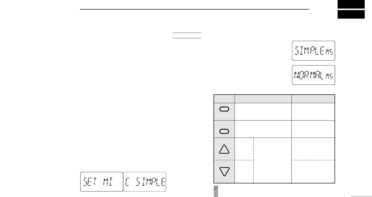
DOptional HM-75A functions
This item turns the microphone sim-
ple mode ON or OFF. Microphone
simple mode is used to change the
function assignments for switches on
the optional HM-75A
REMOTE CON
-
TROL MICROPHONE
as below. This as-
signment is convenient for 3-channel
use of simple operation.
AT
POWER ON
for microphone simple mode
SWITCH NORMAL SIMPLE
VHF/UHF
Toggles VHF and UHF.
No function in memory mode.
MONITOR
Toggles squelch be-
tween open/close.
VFO/MEMORY
Toggles VFO and memory
mode.
UP M1
Selects memory chan-
nel 1.
DOWN M2
Selects memory chan-
nel 2.
Change the fre-
quency or memory
channel when
pushed.
Starts previously
selected scan
when pushed and
held.
A
NOTE: VFO mode cannot be selected via the microphone
when SIMPLE mode is selected.
B
CALL
Selects the call chan-
nel.
5OTHER FUNCTIONS
24
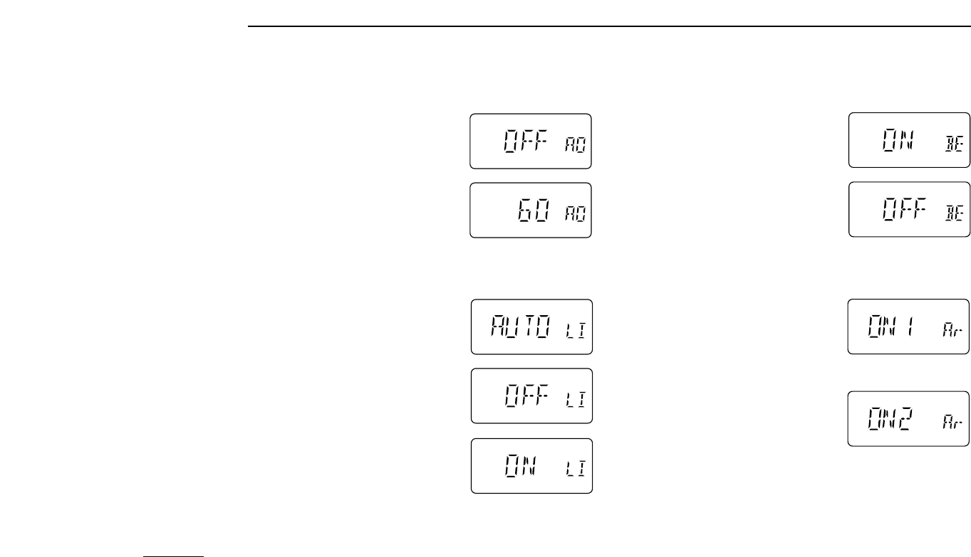
DBeep tones ON/OFF
Beep tones can be turned ON or OFF
as you prefer.
DAuto repeater function (U.S.A. only)
The U.S.A. version automatically acti-
vates repeater settings (duplex
ON/OFF, duplex direction, tone en-
coder ON/OFF) when the operating
frequency falls within the general re-
peater output frequency range. The
offset frequency and repeater tone fre-
quency are not changed by the auto
repeater function.
DAuto power OFF
This item allows you to set a time at
which the transceiver will automati-
cally turn OFF. The power OFF time
can be set to 20, 40, 60 min. or
turned OFF.
DFunction display backlighting
When set to AUTO, display backlight-
ing automatically turns on when a key
is pushed; when set to OFF display
backlighting cannot be turned ON;
when set to ON display backlighting
remains ON continuously.
Activates for duplex
only.
Activates for duplex
and tone.
5
OTHER FUNCTIONS
25
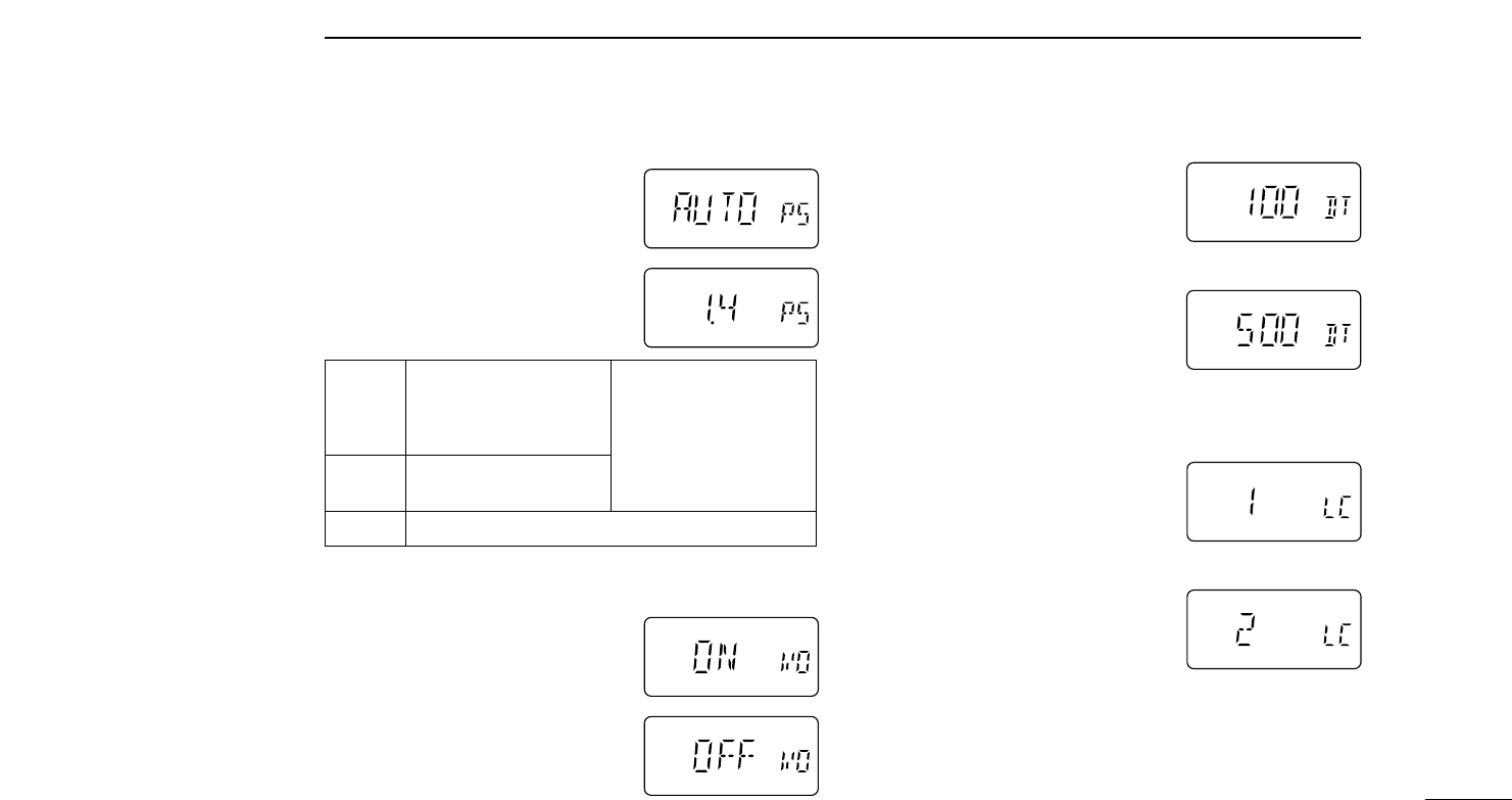
DPower saver duty cycle
This item sets the power saver duty
cycle — the ratio of receive circuit ON
to receive circuit OFF while standing
by. The duty cycle can be set to
AUTO, 1:4 or OFF. Setting to AUTO
conserves the most battery power.
DBattery voltage indication ON/OFF
This item sets the battery voltage in-
dication ON or OFF. When set to ON,
the battery voltage is indicated for 2
sec. at power ON (LOW V, 4.5–16 V
in 0.5 V steps). If the voltage sur-
passes 16 V, “OVER V” appears and
flashes regardless of this setting.
DDTMF speed
When slow DTMF transmission
speeds are required (such as for
some repeaters) the transceiver’s rate
of DTMF transmission can be ad-
justed.
DLCD contrast
This item sets function display con-
trast to one of 2 levels. “1” is for low
contrast and “2” is for high contrast.
fastest (100 msec. intervals)
slowest (500 msec. intervals)
low contrast
high contrast
AUTO Selects “1:4” duty ratio
when receiving no signal
for 5 sec., then “1:8” 60
sec. after that.
1:4 Standby : 125 msec.
circuit idle: 500 msec.
OFF No power save function.
The power saver is deacti-
vated when more than
12 V DC is connected to
the [DC13.5V] jack.

5OTHER FUNCTIONS
26
■CPU resetting
Reset the the CPU before operating the transceiver for the
first time, or when the internal CPU malfunctions.
➥While pushing [MR] + [VFO] + [BAND] turn power ON to
reset the transceiver.
CAUTION: Resetting the CPU returns all pro-
grammed contents to their default settings.
■Channel indication
mode
Channel indication mode is used to simplify operation. In this
mode only pre-programmed memory channel numbers are
displayed and functions are limited ([POWER], [LOCK], [PTT],
[MONI], [H/L], [SCAN] and the tuning dial are functional).
➥While pushing [MR], push [POWER] to turn power ON.
• Repeat this operation to return to nor-
mal indication.
• Needed frequencies must be pro-
grammed into memory channels in
advance.
AT
POWER ON
AT
POWER ON

TROUBLESHOOTING 6
27
If your transceiver seems to be malfunctioning, please check
the following points before sending it to a service center.
PROBLEM POSSIBLE CAUSE SOLUTION REF.
No power comes on. • The battery is exhausted.
(A slight current flows in the circuits even when
the power is OFF.)
• Poor plug connection to the external DC power
cable.
• Charge the battery pack or place new dry cell bat-
teries in the battery case.
(Remove the battery pack if you will not be using
the transceiver for a long time.)
• Check the connector or remove and replace the
cable.
pgs. 7,
8
—
Transmitting is impossible. • The battery is exhausted. • Charge the battery pack or place new dry cells in
the battery case.
pgs. 7,
8
Frequency cannot be set. • Memory mode, call channel or channel indication
mode is selected.
• The lock function is activated.
• Push [VFO] to select VFO mode.
• Set [LOCK] down to deactivate the lock function.
p. 10
p. 12
Scan does not function. • The same frequencies are programmed into XA
and XB.
• Program different frequencies. p. 18
[Y] or [Z] keys do not func-
tion when using the optional
HM-75A.
• Memory channels 1 and/or 2 are not programmed
and simple mode is selected.
• Program the memory channels or set to micro-
phone normal.
p. 15
Squelch does not open for
received signals.
• Tone squelch is activated. • Turn OFF the tone squelch. p. 21
No beep sounds even when
a key is pushed.
• Beep tones are turned OFF in initial set mode. • Set beep tones ON in initial set mode. p. 24
OPTIONS
7
28
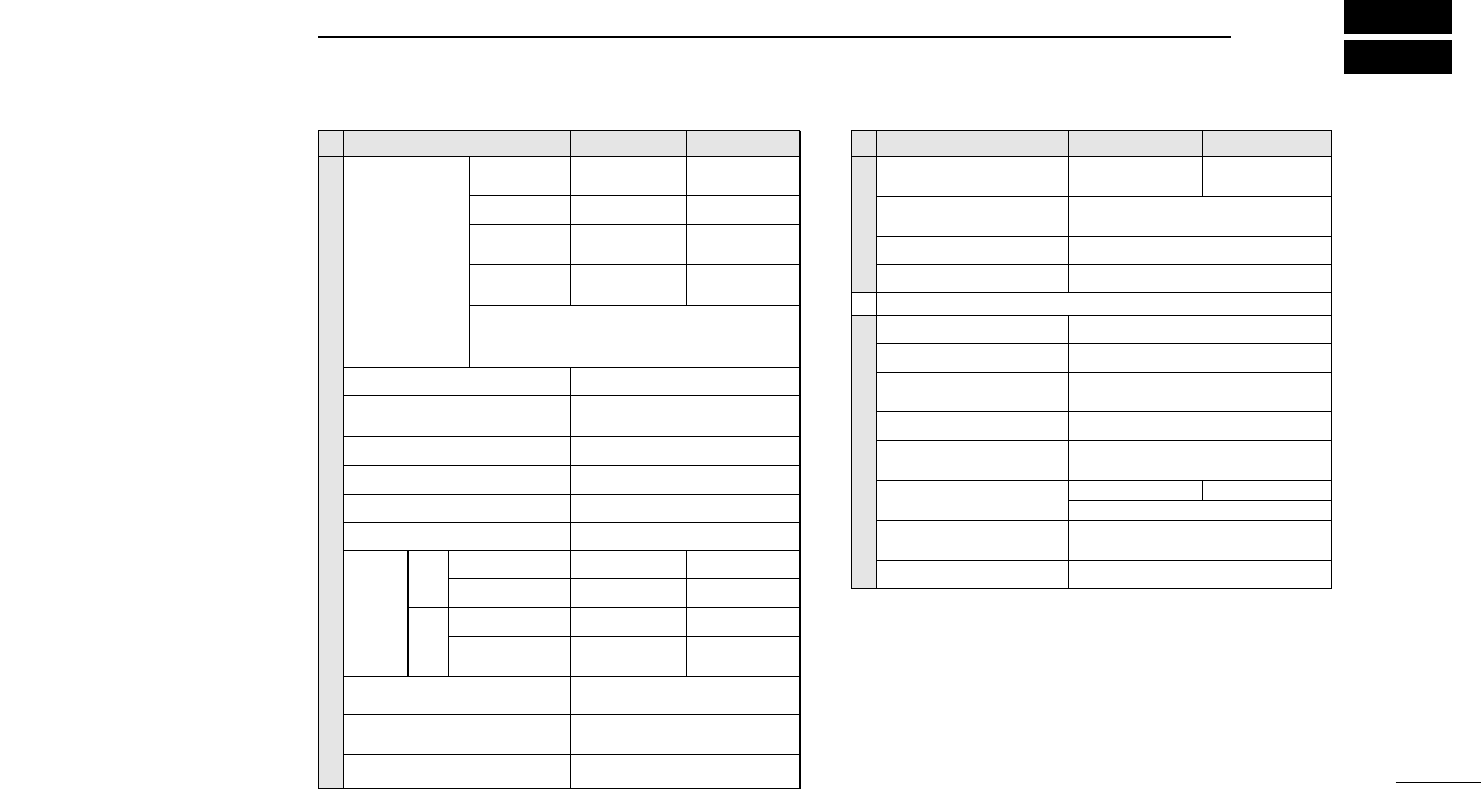
DBattery packs
In the output power and operating period columns, bracketed values
refer to the 440(430) MHz band.
*1Operating periods are calibrated for the following conditions:
Tx : Rx : standby=1 : 1 : 8 min.
*2Operating period depends on alkaline cells used.
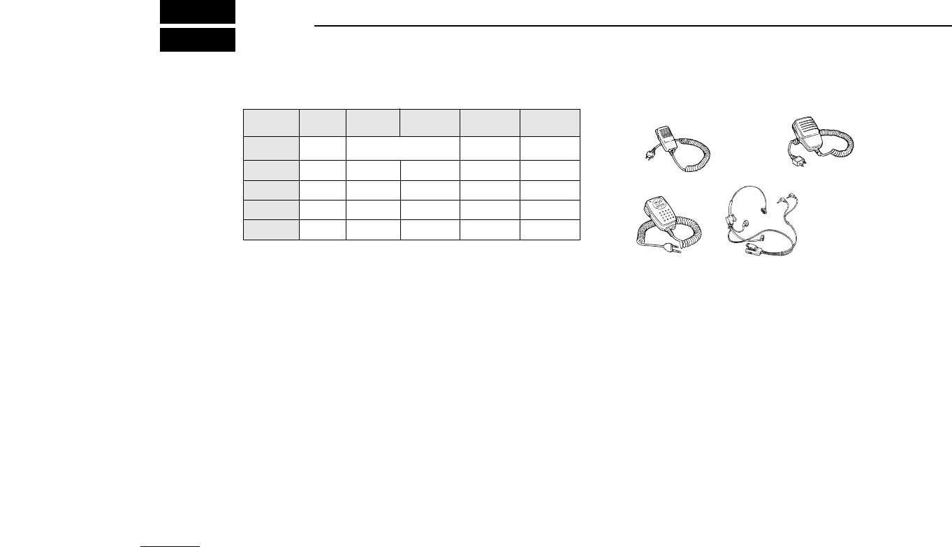
DSpeaker-microphones
DOthers
MB-30 MOUNTING BRACKET
For mounting the transceiver on the inside door panel of a vehicle or
on a wall.
LC-136/LC-137 CARRYING CASES
LC-136: for IC-T7H with BP-170/171/172.
LC-137: for IC-T7H with BP-173/180.
SP-13 EARPHONE
Provides clear receive audio in noisy environments.
CS-T7 CLONING SOFTWARE + OPC-478 CLONING CABLE
Provide quick and easy programming of memory channels, memory
names and set mode contents, etc. via a PC.
DChargers and cables
BC-110A/D/V WALL CHARGER
Regularly charge battery packs attached to the transceiver in 15 to 20
hrs.
BC-119 DESKTOP CHARGER + AD-56 BATTERY PACK ADAPTER
Rapidly charge battery packs in 1 to 1.5 hrs. depending on the bat-
tery pack. An AC adapter is packed with the BC-119. The AD-56 must
be used with the BC-119 for charging the battery pack. The CP-17L or
OPC-515L can be used instead of the supplied AC adapter.
CP-12L CIGARETTE LIGHTER CABLE WITH NOISE FILTER
For operation and charging via a 12 V cigarette lighter socket.
OPC-254L DC POWER CABLE
For operation and charging via an external power supply.
HM-46
HM-75A
HM-54
HS-85 HEADSET
• PTT switch
• VOX
• One-touch PTT for
hands-free operation
Remote control
capability (see p. 23 for details)
BATTERY
PACK HEIGHT
(mm/in) VOLTAGE CAPACITY OUTPUT
POWER
OPER.
PERIOD*
1
BP-170 63.5/2.5 Battery case for
R6(AA) x 4 alkaline cells 2.0 (1.5) W 20 (19) h*2
BP-171 63.5/2.5 4.8 V 700 mAh 2.0 (1.5) W 6.2 (5.5) h
BP-172 63.5/2.5 4.8 V 950 mAh 2.0 (1.5) W 8.3 (7.5) h
BP-173 75.5/3.0 9.6 V 650 mAh 5 (4.5) W 4.3 (4.2) h
BP-180 75.5/3.0 7.2 V 600 mAh 3.9 (2.8) W 4.2 (4.2) h
29
SPECIFICATIONS 8
VHF UHF
GENERAL
Frequency
coverage
(MHz)
U.S.A. Tx: 144–148
Rx: 118–174*1Tx: 430–450*2
Rx: 400–470*2
Europe, U.K. 144–146 430–440
430–440
Guaranteed ranges are:
*1144–148
*2440–450
*3430–440
Mode FM (F3E)
±5 ppm
(0°C to +50°C; +32°F to +122°F)
Tuning steps (kHz)
5, 10, 12.5, 15, 20, 25, 30 or 50
Antenna connector BNC (50 Ω)
Usable battery pack/case
Tx: 430–440
Rx: 400–470*3
Current drain
(at 13.5 V, typ.)
See options on page 28.
Tx: 144–148
Rx: 118–174*1
Asia
Tx: 144–148
Rx: 136–174*1
Italy
Frequency stability
External DC power
4.5 to 16 V DC (negative ground)
190 mA
1.6 A1.6 AHigh
Tx
180 mARated audio
Rx Power saved
(at 9.6 V)
Low 600 mA 700 mA
16 mA (average) 18 mA (average)
Weight (with BP-180)
Dimensions (with BP-180)
(projections not included)
320 g; 11.3 oz
57(W)×122(H)×29(D) mm;
21⁄4(W)×413⁄16(H)×15⁄32(D) in
Usable temperature range –10°C to +60°C;
(+14°F to +140°F)
VHF
TRANSMITTER
Output power*
(at 13.5 V) 6 W, 0.5 W
(selectable)
Modulation system Variable reactance frequency
modulation
Max. freq. deviation* ±5.0 kHz
Ext. microphone jack 2.5 mm (1⁄10 in) 3-conductor/2 kΩ
RECEIVER
Receive system
Double conversion superheterodyne
Intermediate frequencies
Sensitivity*
(12 dB SINAD) Less than 0.18 µV
Squelch sensitivity Less than 0.18 µV
Selectivity More than 15 kHz/–9 dB
Less than 30 kHz/–50 dB
Spurious and image
rejection ratio* More than 60 dB
Audio output power*
(at 13.5 V) More than 500 mW
(at 10% distortion with an 8 Ωload)
Ext. microphone jack 3.5 mm (1⁄8in) 3-conductor/8 Ω
UHF
*Specifications guaranteed at a transceiver temperature of +25°C (+77°F).
All stated specifications are subject to change without
notice or obligation.
More than 50 dB at IF⁄2
More than 50 dB
1st: 45.15 MHz 2nd: 450 kHz
6 W, 0.5 W
(selectable)
30
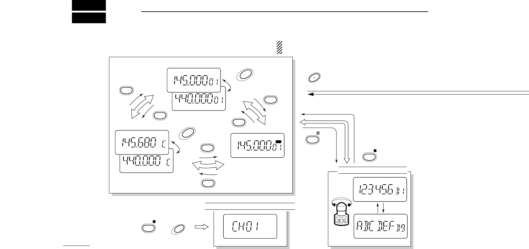
MODE ARRANGEMENT
9
CHANNEL INDICATION MODE
VFO MODE
MEMORY MODE
CALL MODE
MR
DTMF MEMORY MODE
+
AT POWER ON
See p. 26 for details
push for 1 sec.
push for
1 sec.
VFO
VFO
MR
MR
CALL
CALL
BAND
BAND
CLR MHz
VFO
A
POWER
DTMF•M
SET
SKIP
MR
.
H L
B
NOTE: Displays for set and initial set modes show the de-
fault settings—rotate [DIAL] to change the condition.
31
9
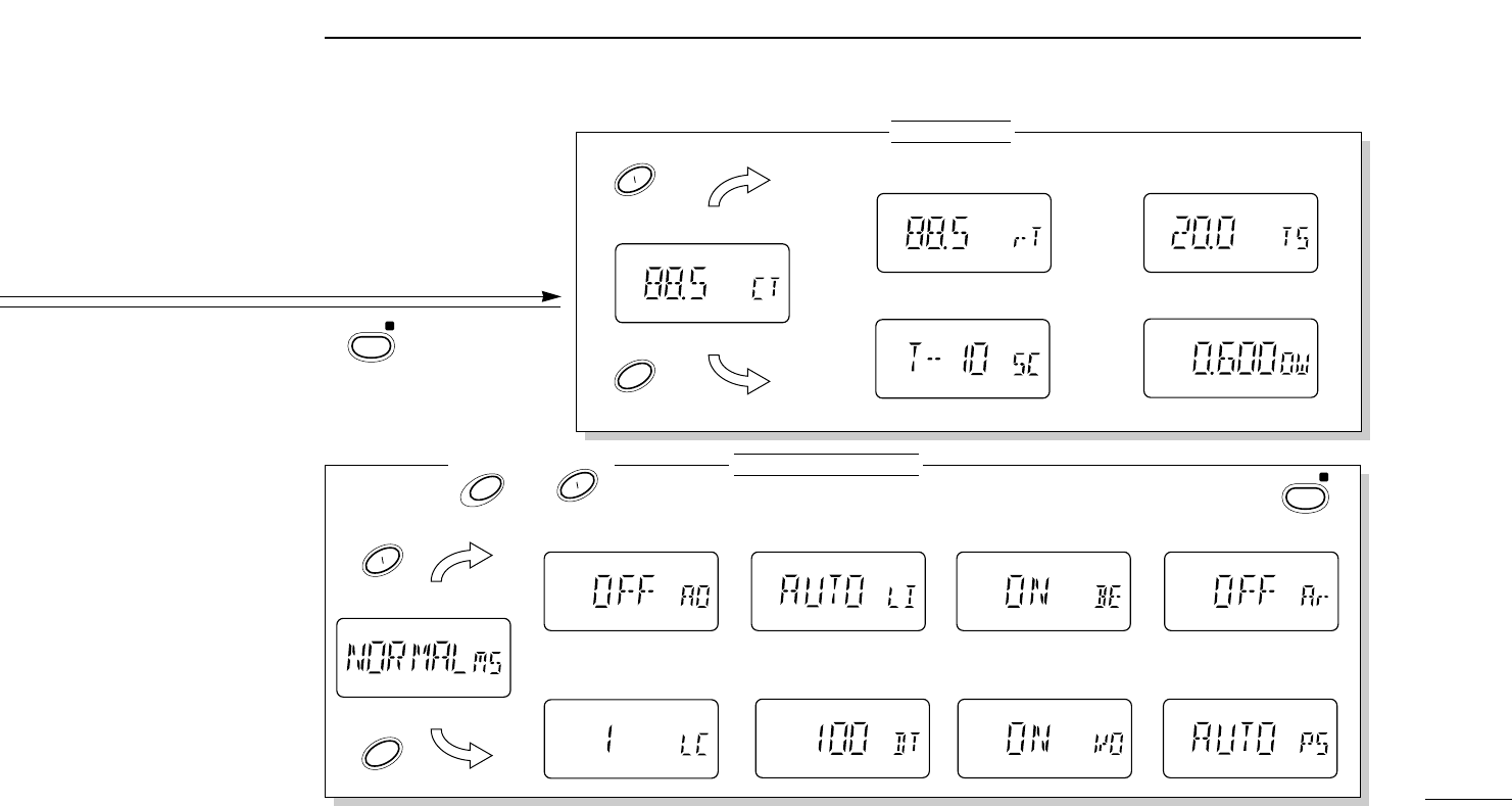
MODE ARRANGEMENT
SET MODE
INITIAL SET MODE
MIC simple mode (p. 23)
Auto power OFF (p. 24) LCD backlight (p. 24)
LCD contrast (p. 25) DTMF speed (p. 25)
Offset frequency* (p. 14)
Auto repeater (p. 24)
U.S.A. version only
Beep tones (p. 24)
Battery voltage (p. 25)
Tuning step* (p. 11)
*Cannot be selected when entering set mode from a memory or call channel.
Power saver duty (p. 25)
Scan resume condition (p. 20)
+
TO ENTER at power ON TO EXIT
Repeater tones (p. 14)
T
CTCSS tones (p. 21)
TSQL
POWER
DUP
SET
TONE
DUP
TONE
H L
SET
H L
SET
H L
CLR MHz
VFO
A
CLR MHz
VFO
A

6-9-16 Kamihigashi, Hirano-ku, Osaka 547-0002 Japan
A-5551S-1EX
Printed in Japan
© 1998 Icom Inc.