ICOM orporated IC-T81A User Manual manual
ICOM Incorporated manual
UserManual.wiki
>
ICOM orporated
>
IC T81A User Manual
manual
Navigation menu
Upload a User Manual
Namespaces
Wiki Guide
HTML
PDF
Info
Views
User Manual
Discussion / Help
Navigation
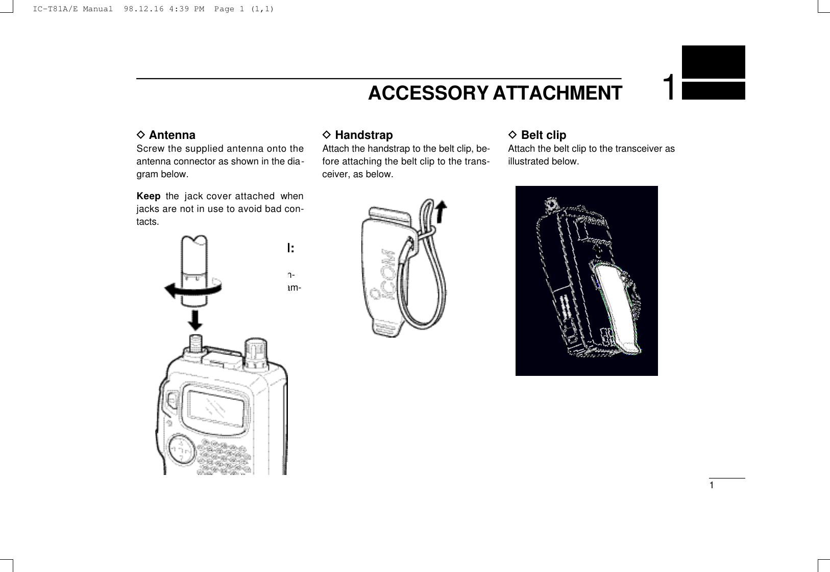
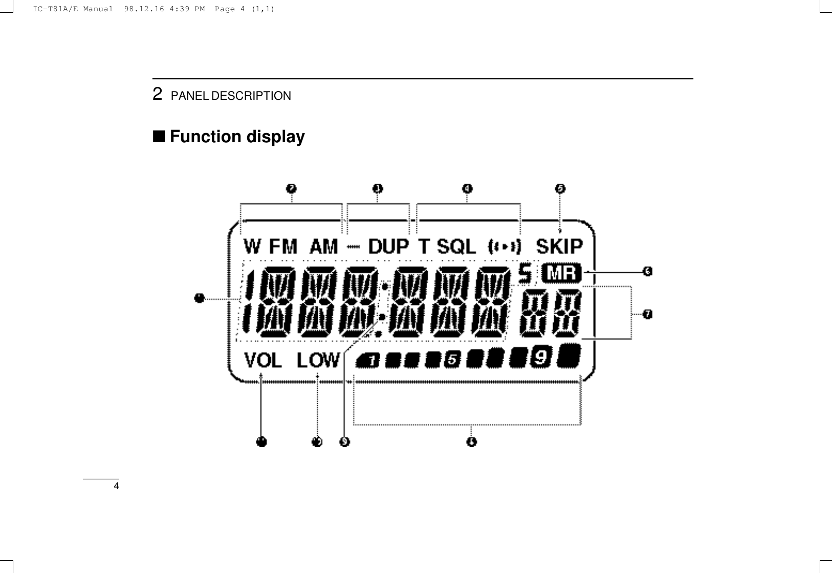
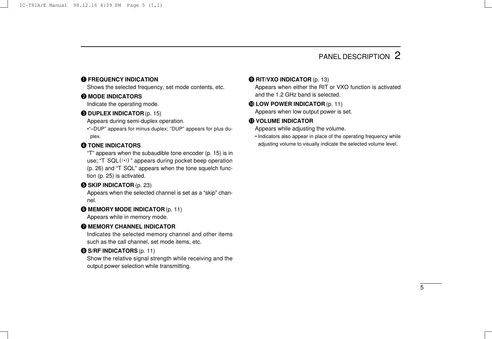
![PANEL DESCRIPTION22qMULTIFUNCTION SWITCH [MULTI]➥Push to select the tone or duplex menu. (pgs. 15–17);push for 1 sec. to enter set mode (pgs. 27–29).➥Push ↕to increase/decrease the volume (p. 11).➥Push ↔to change the operating band; push for 1 sec.to start a scan (p. 23).wSQUELCH SWITCH [SQL] (p. 11)➥Push and hold to open the squelch.➥While pushing, rotate [DIAL] to adjust the squelch set-ting.eTX/RX INDICATOR (p. 11)Lights red while transmitting; green while receiving (orwhen the squelch is open).rPTT SWITCH [PTT] (p. 11)Push and hold to transmit; release to receive.tPOWER SWITCH [PWR] (p. 9)Push for 1 sec. to turn power on and off.yANTENNA CONNECTOR (p. 1)Connects the supplied antenna.uEXTERNAL SPEAKER AND MICROPHONE JACKS[SP/MIC]Connect an optional speaker-microphone or headset, if de-sired. The internal microphone and speaker will not func-tion when either is connected. (See p. 33 for options.)■Switches, controls, keys and connectorsNOTE: In this manual—Push [MULTI] means push directly;Push [MULTI(↕)] means push up or down; andPush [MULTI(↔)] means push left or right. See qabove.IC-T81A/E Manual 98.12.16 4:39 PM Page 2 (1,1)](https://usermanual.wiki/ICOM-orporated/IC-T81A/User-Guide-22079-Page-6.png)
![32PANEL DESCRIPTION☞N O T E : When connecting or disconnecting an externalspeaker-microphone, first turn off power to the transceiver.iTUNING CONTROL [DIAL]Changes the operating frequency; memory channel inmemory mode; set mode contents in set mode, etc.oVFO/CLEAR KEY [VFO(CLR/MHz)Å]➥Push to select VFO mode. (p. 9)➥Cancels some functions such as digit input before entry,scans, etc.➥Push and hold for 1 sec., then rotate [DIAL] to changethe MHz digit. (p. 10)➥While pushing [PTT], this key sends a DTMF “A.” (p. 21)!0 MEMORY MODE KEY [MR(MW)ı]➥Push to select memory mode. (p. 11)•“X” appears while in memory mode.➥Push for 1 sec. to enter memory write mode. (p. 18)➥While pushing [PTT], this key sends a DTMF “B.” (p. 21)!1 CALL KEY [CALLÇ]➥Push to select the call channel. (p. 19)➥While pushing [PTT], this key sends a DTMF “C.” (p. 21)!2 OUTPUT POWER KEY [H/L(LOCK)Î]➥Push to toggle between low and high power. (p. 11)•“LOW” appears while low power is selected.➥Push for 1 sec. to toggle the lock function on/off. (p. 11)• “L” appears while the lock function is activated.➥While pushing [PTT], this key sends a DTMF “D.” (p. 21)!3 RIT KEY [RIT(TSCAN)#] (p. 13)➥Push, then rotate [DIAL] to change the RIT/VXO setting.•This function is only available for the 1.2 GHz band and RITor VXO must be activated in set mode (p. 13).➥Push for 1 sec. to turn the tone scan function on/off. (p.26)➥While pushing [PTT], this key sends a DTMF “F.” (p. 21)!4 DIGIT KEYS➥Input the specified digit during frequency input, memorychannel selection, etc.➥Transmit the DTMF code of the specified digit whilepushing [PTT]. (p. 21)!5 MHz KEY [• (M)] (p. 10)➥Used as a shortcut for inputting frequencies.➥Transmits an “E” for DTMF operation while pushing[PTT].!6 EXTERNAL DC POWER JACK [DC13.5V]Allows you to operate the transceiver with a 4.5 to 16 V DCpower source using optional cables, CP-12Lor OPC-254L.uCAUTION: DO NOT connect when a battery case is at-tached.IC-T81A/E Manual 98.12.16 4:39 PM Page 3 (1,1)](https://usermanual.wiki/ICOM-orporated/IC-T81A/User-Guide-22079-Page-7.png)
![94BASIC OPERATION■Power ON☞NOTE: Charge the battery pack before turning power onfor the first time (pgs. 6–8)Push and hold [PWR] for 1 sec. to turn power on.•Current battery voltage may be dis-played for 2 sec.•The display shows the approx. volt-age in 0.5 V steps.•When the battery voltage is lowerthan a specified level (varies accord-ing to battery pack used), “LOW V ”appears. Charge the battery pack inthis case; when using a battery casewith alkaline cells this indication doesnot appear.•If “OVER V” appears, U N P L U G t h eexternal DC plug immediately. Con-nected voltage is over 16 V and coulddamage the transceiver.■Setting a frequencyDVia the keypad(from the MHz digits)➀Push [VFO] to select VFOmode.➁Push digit keys correspond-ing to the desired frequency.•When inputting a frequency inthe 50 MHz band, it is neces-sary to input the decimalpoint.•When a digit is mistakenlyinput, push [VFO] and inputfrom the beginning.•When an unacceptable fre-quency is input, the display re-verts to the previouslydisplayed frequency.•“0,” “2,” “5” and “7” are accept-able as the 1 kHz digit inputdepending on the 10 kHz digit.IC-T81A/E Manual 98.12.16 4:39 PM Page 9 (1,1)](https://usermanual.wiki/ICOM-orporated/IC-T81A/User-Guide-22079-Page-13.png)
![■Setting tuning stepsThe transceiver has 9 tuning steps* (each band has indepen-dent settings) as follows:5 kHz 10 kHz 12.5 kHz 15 kHz 20 kHz25 kHz 30 kHz 50 kHz 100 kHz*The 5 and 15 kHz steps are not available on the 1200 MHz band.➀Push [VFO] to select VFO mode.➁Push [MULTI(↔)] to select the desired band.➂Push [MULTI] for 1 sec. to enter set mode.➃Push [MULTI(↕)] one or more timesuntil “TS” appears.➄Push [MULTI(↔)] (or rotate [DIAL])to select the desired tuning step.➅Push [VFO] to exit set mode.✔CONVENIENTSelect a tuning step that matches the frequency intervals ofrepeaters in your area.104BASIC OPERATIONDVia the keypad(from the decimal point)➀Push [VFO] to select VFOmode.➁Push [•] to leave the MHzsetting as is and input fromthe kHz digits.DOther methods➥Via the [DIAL]: Rotate [DIAL] to change the frequency ac-cording to the set tuning steps.➥Via the MHz STEP: Push [( V F O )MHz] for 1 sec., then ro-tate [DIAL] to change the frequency in 1 MHz steps.USINGSET MODEIC-T81A/E Manual 98.12.16 4:39 PM Page 10 (1,1)](https://usermanual.wiki/ICOM-orporated/IC-T81A/User-Guide-22079-Page-14.png)
![114BASIC OPERATION■Selecting a memory channel➀Push [MR] to select mem-ory mode.➁Push [MULTI(↔)] (or rotate[DIAL] or push digit keys) toselect the desired memorychannel.•Only programmed memorychannels can be selected.•Memory channels 1–9 arepreceded with a “0” when se-lecting with the digit keys;push “0@” to select scan edge0A, push “0?” to select scanedge 0B.■Lock functionPush [(H/L)LOCK] for 1 sec. to togglethe lock function on and off.• “L” appears while the lock function is ac-tivated.•[PTT], [PWR], [MULT I (↕)] (volume), [SQL] and [H/L] can be usedeven when the lock function is activated.■Receive and transmit➀Push [PWR] for 1 sec. to turn power on.➁Push [MULTI(↕)] to set a volume level.➂Set the squelch level.•While pushing [SQL], rotate [DIAL].•10 selections are available, “OPEN,”“AUTO,” and “SQL1 to “SQL8.”➃Set an operating band and frequency.•When a signal is received:➟Squelch opens and audio is emitted from the speaker.➟The [TX/RX] indicator lights green.➄Push [H/L] to toggle output power between high and low.•“LOW” appears when low output power is selected.➅Push and hold [PTT] to transmit; then speak into the mic.•Do not hold the microphone too close to your mouth or speaktoo loudly. This may distort the signal.•The S/RF indicator shows the output power selection.•The [TX/RX] indicator lights red.➆Release [PTT] to return to receive.✔CONVENIENTMonitor function: Push and hold [SQL] to listen to weak sig-nals that do not open the squelch.IC-T81A/E Manual 98.12.16 4:39 PM Page 11 (1,1)](https://usermanual.wiki/ICOM-orporated/IC-T81A/User-Guide-22079-Page-15.png)
![124BASIC OPERATION■FM broadcast receptionThe transceiver can receive FM radio broadcasts. These aretypically in the range 76–107.995 MHz (88–107.995 for someversions) and are in WFM receive mode.To select the FM broadcast band:➥Push [MULT I (↔)] one or moretimes until “WFM” appears in thed i s p l a y, then rotate [DIAL] to selecta frequency; or,➥Select a frequency with the digit keys directly.•“WFM” automatically appears when a frequency in the range76–107.995 MHz is input.☞N O T E : When pushing [PTT], “OFF” appears indicating thefrequency and mode are outside the permitted range.■Air band reception (USA ver. only)The transceiver can receive frequencies reserved for com-mercial/private aircraft and ground support. These are in therange 118–135.995 MHz and are in AM receive mode.To select the air band:➥Push [MULT I (↔)] one or moretimes until “AM” appears in the dis-play, then rotate [DIAL] to select a frequency; or,➥Select a frequency with the digit keys directly.•“AM” automatically appears when a frequency in the range118–135.995 MHz is input.☞N O T E : When pushing [PTT], “OFF” appears indicating thefrequency and mode are outside the permitted range.■Narrow FM*operation (Eur., France, Italy ver. only)➀Push [MULT I (↔)] one or moretimes to select the 144 MHz band.➁Push [MULTI] for 1 sec. to enter setmode.➂Push [MULTI(↕)] one or more timesto display “MO,” if necessary.➃Push [MULT I ( ↔)] (or [DIAL]) to tog-gle narrow FM operation on andoff.•“FM” appears when narrow FMoperation is on.➄Push [VFO] to exit set mode and return to regular opera-tion.☞*N O T E : FM narrow operation can be set for individualmemory channels or in VFO mode; narrow FM aff e c t sUSINGSET MODEIC-T81A/E Manual 98.12.16 4:39 PM Page 12 (1,1)](https://usermanual.wiki/ICOM-orporated/IC-T81A/User-Guide-22079-Page-16.png)
![134BASIC OPERATION■RIT/VXO function(1200 MHz band)In the 1200 MHz band, differences between actual and dis-played frequencies can often be large. The RIT (receive in-cremental tuning) function allows you to compensate thedisplayed frequency for differences in the actual receive fre-quency; the VXO (variable crystal oscillator) function allowsyou to compensate the displayed frequency for differences inthe actual receive and transmit frequencies.DActivating RIT/VXO➀Select a frequency in the 1200 MHz band (or a memorychannel with a 1200 MHz band frequency; or the 1200MHz band call channel).➁Push [MULTI] for 1 sec. to enter set mode.➂Push [MULTI(↕)] one or more times until “rV” appears.➃Push [MULT I (↔)] one or moretimes to select “RIT” (RIT a c t i v a t e d ,“VXO” (VXO activated) or “OFF”(neither activated)—[DIAL] canalso be used.➄Push [VFO] to exit set mode andreturn to the previously selectedmode.• When RIT or VXO is activated, “:” ap-pears above the decimal point in thefrequency indication (in the 1200 MHz band).USINGSET MODEDAdjusting the frequency with RIT/VXOMake sure that RIT or VXO is activated in set mode and thatthe 1200 MHz band is selected.➀Select a frequency in the 1200 MHz band (or a memorychannel with a 1200 MHz band frequency; or the 1200MHz band call channel).➁Push [RIT] to display the frequencyoffset in kHz.➂Push [MULT I (↔)] one or moretimes (or rotate [DIAL]) to adjustthe frequency offset.•The frequency offset can be set±5 kHz in 1 kHz steps.➃Push [VFO] to return to regular dis-play indication.IC-T81A/E Manual 98.12.16 4:39 PM Page 13 (1,1)](https://usermanual.wiki/ICOM-orporated/IC-T81A/User-Guide-22079-Page-17.png)
![144BASIC OPERATION■Receive modeThe IC-T81A/E allows you to receive frequencies in the 50MHz band in AM mode (as well as to transmit in FM narrowmode in the 144 MHz band for Italy/Europe versions only—see p. 12).➀Push [VFO] to select VFO mode.➁Push [MULT I ( ↔)] one or moretimes to select the 50 MHz band.➂Push [MULTI] for 1 sec. to enter setmode.➃Push [MULT I (↕)] one or more timesuntil “MO” appears.➄Push [MULTI(↔)] (or rotate [DIAL])one or more times to select “AM.”➅Push [VFO] to exit set mode and return to VFO mode.•“AM” appears when frequencies in the 50 MHz band are se-lected.☞NOTE:➥When AM operation is selected, transmit is not possible.When [PTT] is pushed, “OFF” appears.➥AM operation can also be selected for individual mem-ory channels programmed with 50 MHz frequencies. Inthis way you can program individual frequencies for AMreceive while allowing regular transmit/receive for 50MHz frequencies in VFO mode.USINGSET MODEIC-T81A/E Manual 98.12.16 4:39 PM Page 14 (1,1)](https://usermanual.wiki/ICOM-orporated/IC-T81A/User-Guide-22079-Page-18.png)
![155REPEATER OPERATION■GeneralWhen using a repeater, the transmit frequency is shifted fromthe receive frequency by the offset frequency. It is convenientto program repeater info into memory channels (pgs. 18–20).➀Set the operating band and receive frequency (repeateroutput frequency).➁Push [MULTI] to enter duplex set mode.• “D” appears; if “T” appears instead of “D” push [MULTI(↕)] to se-lect “D.”➂Push [MULT I (↔)] (or rotate [DIAL]) one or more times toselect DUP ( plus duplex) or –DUP (minus duplex).•When the auto repeater function is in use (USAversion only) thisselection and steps ➃and ➄are not necessary (p. 17).➃Push [MULTI(↕)] to select tone set mode.•“T” appears.➄Push [MULT I (↔)] (or rotate [DIAL]) to activate the sub-audible tone encoder according to repeater requirements.•Refer to the table of subaudible tone frequencies on the followingpage.➅Push and hold [PTT] to transmit.•The displayed frequency automatically changes to the transmitfrequency (repeater input frequency).•If “OFF” appears, check the offset frequency (p. 16).➆Release [PTT] to receive.➇Push and hold [SQL] to check whether the other station’stransmit signal can be directly received or not.DTone informationSome repeaters require a tone to be accessed. In this case,precede step ➅at left with the required tone.DTMF TONESWhile pushing [PTT], push the desired digit key(s) to transmitDTMF tones.•The transceiver has 9 DTMF memory channels. See p. 21 for de-tails.1750 Hz TONEWhile pushing [PTT], push and hold [MULTI] for 1 to 2 sec.to transmit a 1750 Hz tone signal.✔ConvenientTone scan function: When you don’t know the subaudibletone used for a repeater, the tone scan is convenient for de-tecting the tone frequency.Push [(RIT)TSCAN)] for 1 sec. to activate the tone scan. Seep. 26 for more details.IC-T81A/E Manual 98.12.16 4:39 PM Page 15 (1,1)](https://usermanual.wiki/ICOM-orporated/IC-T81A/User-Guide-22079-Page-19.png)
![165REPEATER OPERATION■Subaudible tonesfor repeater useSome repeaters require subaudible tones to be accessed.Subaudible tones are superimposed over your normal signaland must be set in advance.➀Push [VFO] to select VFO mode.➁Push [MULTI(↔)] to select a band.➂Push [MULTI] for 1 sec. to enter setmode.➃Push [MULTI(↕)] one or more timesuntil “rT” appears.➄Push [MULTI(↔)] (or rotate (DIAL)to select the desired subaudibletone.➅Push [VFO] to enter the selected tone and exit set mode.Available subaudible tone frequencies (unit: Hz)67.0 79.7 94.8 110.9 131.8 156.7 171.3 186.2 203.5 229.169.3 82.5 97.4 114.8 136.5 159.8 173.8 189.9 206.5 233.671.9 85.4 100.0 118.8 141.3 162.2 177.3 192.8 210.7 241.874.4 88.5 103.5 123.0 146.2 165.5 179.9 196.6 218.1 250.377.0 91.5 107.2 127.3 151.4 167.9 183.5 199.5 225.7 254.1USINGSET MODE ■Setting an offsetfrequencyWhen communicating through a repeater, the transmit fre-quency is shifted from the receive frequency by an amountdetermined by the offset frequency.➀Push [VFO] to select VFO mode.➁Push [MULTI(↔)] to select a band.➂Push [MULTI] for 1 sec. to enter setmode.➃Push [MULT I (↕)] one or more timesuntil “OW” appears.➄Push [MULTI(↔)] (or rotate (DIAL)to select the desired offset.•The offset frequency changes according to the selected tuningsteps.•The MHz step may be helpful for large frequency changes—push[(VFO)MHz] for 1 sec.➅Push [VFO] to enter the selected offset and exit set mode.USINGSET MODEIC-T81A/E Manual 98.12.16 4:39 PM Page 16 (1,1)](https://usermanual.wiki/ICOM-orporated/IC-T81A/User-Guide-22079-Page-20.png)
![175REPEATER OPERATION■Auto repeaterfunction (USAversion only)The USAversion automatically activates the repeater settings(duplex, ON/OFF, duplex direction, tone encoder ON/OFF)when the operating frequency falls within or outside of thegeneral repeater output frequency range. The offset and re-peater tone frequencies are not changed by the auto repeaterfunction, reset these frequencies, if necessary.➀While pushing [MULTI], push[PWR] to turn power on and enterinitial set mode.➁Push [MULT I (↕)] one or more timesuntil “Ar” appears.➂Push [MULTI(↔)] (or rotate [DIAL]to select the desired condition.•“OFF”—the auto repeater function isturned off;“ON1”—the auto repeater function ac-tivates for duplex only;“ON2”—the auto repeater function ac-tivates for duplex and tone.➃Push [VFO] to exit initial set mode.USINGINITIAL SET MODE Frequency range and offset directionFREQUENCYRANGE DUPLEX DIRECTION145.200– 145.495 MHz “–DUP” appears146.610– 146.995 MHz147.000– 147.395 MHz “DUP” appears442.000– 444.995 MHz “DUP” appears447.000– 449.995 MHz “–DUP” appears51.620– 51.980 MHz52.500– 52.980 MHz “–DUP” appears53.500– 53.980 MHz1282.000–1287.995 MHz* “–DUP” appears1288.000–1295.995 MHz*When operating in this range, the offset frequency must be set to–12 MHz (see previous page for setting an offset).IC-T81A/E Manual 98.12.16 4:39 PM Page 17 (1,1)](https://usermanual.wiki/ICOM-orporated/IC-T81A/User-Guide-22079-Page-21.png)
![186MEMORY/CALL PROGRAMMING■GeneralThe transceiver has 124 memory channels (100 regular, 10pairs of scan edge channels for mixed bands and 1 call chan-nel for each band—VHF, UHF, 50 MHz and 1200 MHz). Notethat memory channels are not grouped according to band. Inother words, a given memory channel can be programmedwith either a VHF frequency, a UHF frequency, a 50 MHz fre-quency or a 1200 MHz frequency. This is not the case withcall channels. Call channels are band specific.The following can be programmed into memory/call channels:•Operating frequency• Duplex direction with an offset frequency (pgs. 15, 16)• Subaudible tone encoder or tone squelch on/off with a tone(CTCSS) frequency (pgs. 25, 26)•Subaudible tone and tone squelch frequencies (pgs. 16, 25)• Mode—AM, FM, etc. (p. 14)• Skip information* (p. 23)*Except for scan edge memory channels and call channels.☞NOTE:➥Memory channels can be assigned names (of up to 6characters).➥When memory names are assigned, each push of [MR]toggles between frequency and name indication.■Programming a memorychannel➀Push [VFO] to select VFO mode.➁Set the desired frequency:➥Set other data, such as repeaterinformation, if required.➂Push [(MR)MW] for 1 sec.•“X” and the previously selectedmemory channel flash.➃Push [MULTI(↔)] (or rotate [DIAL])to select the desired memory chan-nel.• Call channels and scan edgechannels, as well as regular chan-nels, can be programmed in thisway.•Only the decimal point appearsfor memories not yet pro-grammed.•If you want to confirm the VFO frequency, push [MR] mo-mentarily—the VFO frequency briefly appears.➄Push [(MR)MW] for 1 sec. to program.• “X” and the memory channel number stop flashing.• VFO mode is selected.IC-T81A/E Manual 98.12.16 4:39 PM Page 18 (1,1)](https://usermanual.wiki/ICOM-orporated/IC-T81A/User-Guide-22079-Page-22.png)
![196MEMORY/CALL PROGRAMMING■Memory editingMemory (call) channel contents can be moved to VFO or toanother memory.DTransferring a memory (call) channel’scontents➀Select the memory (call) channel tobe transferred:➥Push [MR] ([CALL)]) to selectmemory (call) mode.➥Push [MULT I (↔)] (or rotate[DIAL]) to select the memory(call) channel.➁Push [(MR)MW] for 1 sec.•“VF” appears and flashes with “X”and the previously selected VFO fre-quency appears..To transfer the contents to VFO:➂Push [(MR)MW] for 1 sec.•The contents are transferred and VFO mode is selected.To transfer the contents to another memory (call) channel:➂Push [MULT I (↔)] (or rotate [DIAL]) to select the memory(call) channel to be transferred to.➃Push [(MR)MW] for 1 sec.•The contents are transferred and memory (call) mode is selected.DClearing a memory➀Push [MR] to select memory mode.➁Push [MULTI(↔)] (or rotate [DIAL]) to select a channel tobe cleared.➂Push [VFO] to select VFO mode.➃Push [( M R )MW] for 1 sec. to entermemory menu mode.•“X” and a memory channel numberflash.➄Push [MULTI(↕)] to display “CLR.”•Scan edge channels 0A/0B and callchannels cannot be cleared.➅Push [( M R )MW] for 1 sec. to clearthe previously selected memorychannel.•“X” and a memory channel numberflash and the previously stored infor-mation is erased.➆Push [VFO] to select return to VFOmode.☞N O T E : Be careful—the contents of cleared memories c a n-not be recalled.IC-T81A/E Manual 98.12.16 4:40 PM Page 19 (1,1)](https://usermanual.wiki/ICOM-orporated/IC-T81A/User-Guide-22079-Page-23.png)
![206MEMORY/CALL PROGRAMMING■Memory namesMemory channels can be programmed with names of up tosix characters.➀Push [VFO] to select VFO mode (or select a memory chan-nel).➁Push [(MR)MW] for 1 sec.•“X” and the previously selectedmemory channel number flash.➂Push [MULTI(↔)] (or rotate [DIAL])to select the desired memory chan-nel.➃Push [MULT I (↕)] so that “NAME”appears.•Not valid for call channels.➄Push [MULTI] to enter name editingmode.•The first character of the name fla s h e s .➅Rotate [DIAL] (or push [MULT I (↕) ]to select a character; then, push[MULTI(↔)] to advance to the nextcharacter.➆Repeat step ➅until the desiredname appears.➇Push [MULTI] to program the nameand return to the “NAME” display;then push [VFO] to return to VFOmode.• Push [(MR)MW] for 1 sec. to erase a channel’s name and returnto VFO mode.•When in memory mode push [MR] to toggle between memoryname indication and frequency indication.☞NOTE: To clear a memory name (or remove one or morecharacters from a name) without clearing the rest of thememory channel contents, follow steps ➀to ➇at left andinsert an underscore “_” in place of other characters insteps ➅and ➆.IC-T81A/E Manual 98.12.16 4:40 PM Page 20 (1,1)](https://usermanual.wiki/ICOM-orporated/IC-T81A/User-Guide-22079-Page-24.png)
![217DTMF MEMORY■Programming a DTMF codeThe transceiver has 9 DTMF memory channels (D1 to D9) forstorage of often-used DTMF codes of up to 16 characters.➀Push [( M R )MW] for 1 sec. to entermemory write mode; then push[MULTI(↕)] to enter DTMF memorymode.•One of “D1” to “D9” appears andflashes.➁Rotate [DIAL] (or push [MULT I (↔) ] )to select the desired channel.➂Push [MULTI] to enter DTMF pro-gramming mode.•The first character of the DTMF codeflashes.➃Push digit keys (or rotate [DIAL] orpush [MULT I (↕)]) to enter the de-sired DTMF character; then push[MULTI(↔)] to advance to the nextcharacter.•Amaximum of 16 characters can be input.•Pushing [MULTI(↕)] can also be used to enter DTMF characters.•When pushing [SQL], the programmed contents can be moni-tored.➄Push [MULTI] to input the digits; then push [VFO] to exitDTMF programming mode.■Transmitting a DTMF codeDUsing a DTMF memory channel➀Push [( M R )MW] for 1 sec. to enter memory write mode;then push [MULTI(↕)] to enter DTMF memory mode•One of “D1” to “D9” appears.➁Rotate [DIAL] (or push [MULT I (↔)]) to select the desiredchannel.➂While pushing [PTT], push [SQL] to transmit the selectedDTMF channel’s contents.DManual DTMF code transmission➀While pushing [PTT], push digit keys to transmit a DTMFcode manually.➁Release [PTT] to return to receive.DDTMF transmit speedWhen slow DTMF transmission speeds are required (such asfor some repeaters) the transceiver’s rate of DTMF transmis-sion can be adjusted.➀While pushing [MULTI], push [PWR] to turn power on andenter initial set mode.➁Push [MULT I (↕)] one or more timesuntil “DT” appears.➂Rotate [DIAL] (or push [MULT I (↔) ] )to select the a transmit speed.•100 (default), 200, 300 and 500 msec. are available.➃Push [VFO] to exit initial set mode.USINGINITIAL SET MODEIC-T81A/E Manual 98.12.16 4:40 PM Page 21 (1,1)](https://usermanual.wiki/ICOM-orporated/IC-T81A/User-Guide-22079-Page-25.png)
![228SCAN FUNCTIONS■Scan typesFULL SCAN (p. 23)PROGRAMMED SCAN (p. 23)MEMORY SCAN (p. 23MEMORY SKIP SCAN (p. 23)☞NOTE: Push [MULTI(↔)] during full/programmed scan tochange the band being scanned or to select a different pairof scan edges.Push [MULT I (↔)] during memory (skip) scan to change thememory channel groups: 1.2 GHz, VHF, UHF, 50 MHz, airband or WFM programmed memories; or, all programmedmemories.Repeatedly scans all fre-quencies over a selectedband.Repeatedly scans all pro-grammed memory chan-nels.Repeatedly scans be-tween two user-pro-grammed frequencies.Used for checking for fre-quencies within a speci-fied range such asrepeater output frequen-cies.Repeatedly scans allmemories, except thoseset as skip channels.IC-T81A/E Manual 98.12.16 4:40 PM Page 22 (1,1)](https://usermanual.wiki/ICOM-orporated/IC-T81A/User-Guide-22079-Page-26.png)
![238SCAN FUNCTIONS■Full/programmed scan➀Push [VFO] to select VFO mode, if necessary.➁Push [MULT I (↔)] for 1 sec. to start the scan; after that,each push of [MULTI(↔)] selects a different scan range.•To change the scan direction, rotate [DIAL].➥The following scan ranges are selectable:•“ALL50” for full scan on the 50 MHz band.•“ALL144” for full scan on the 144 MHz band.•“ A L L 430” or “ALL 440” for full scan on the 430(440) MHzband.•“ALL WFM” for full scan on the WFM (FM broadcast) band.•“ALL 118” for full scan on the air band.•“ALL1200” for full scan on the 1.2 GHz band.•“PROG 0” to “PROG 9” for one of the programmed scans.➂To stop the scan, push [VFO].☞N O T E : For programmed scan, scan edges must be pro-grammed in advance (0A/0B are programmed by default).Program scan edges in the same manner as regular mem-ory channels (p. 18).If the same frequencies are programmed into a pair of scanedges, programmed scan does not proceed.■Memory (skip) scan➀Push [MR] to select memory mode, if necessary.➁Push [MULT I (↔)] for 1 sec. to start the scan; after that,each push of [MULTI(↔)] selects a different scan group.•To change the scan direction, rotate [DIAL].➥The following memory groups are selectable:•“SELALL” scans all programmed memory channels.•“SEL50” scans programmed memories in the 50 MHz band.•“ S E L 144” scans programmed memories in the 144 MHzband.•“SEL430” or “SEL440” scans programmed memories in the430(440) MHz band.•“SELWFM” scans all programmed WFM channels.•“SEL118” scans all programmed air band channels.•“ S E L 1200” scans programmed memories in the 1.2 GHzband.➂To stop the scan, push [VFO].☞N O T E : For memory skip scan, program memory channelsyou don’t want to search, as “skip” channels (p. 24). Scanproceeds as above except that any channels specified asskip channels are not searched.IC-T81A/E Manual 98.12.16 4:40 PM Page 23 (1,1)](https://usermanual.wiki/ICOM-orporated/IC-T81A/User-Guide-22079-Page-27.png)
![248SCAN FUNCTIONS■Skip channel settingMemory channels can be set to be skipped during memoryscan. This is useful to speedup the memory scan interval.➀Push [MR] to select memory mode.➁Push [(MR)MW] for 1 sec. to enter memory write mode.➂Rotate [DIAL] (or push [MULT I (↔)]) to select a memorychannel.➃Push [MULTI(↕)] twice times to select “SKIP.”➄Push [MULTI(↔)] (or rotate [DIAL])to toggle the skip setting for the se-lected channel ON/OFF.•“SKIP” appears when the channel isset as a skip channel.➅Push [VFO] to program the settingand exit memory write mode.☞N O T E : Scan edge channels, 0A to 9B, cannot be set toshow “SKIP” settings, however, they will be skipped dur-ing scan.■Scan resumeconditionThe resume condition can be selected as a pause or timerscan. This setting is common for all scans.USINGSET MODEWhen receiving a signal, pausescan pauses until the signal dis-appears; timer scan pauses for10 sec.➀Push [MULTI] for 1 sec. to enter setmode.➁Push [MULTI(↕)] one or more timesuntil “SC” appears.➂Push [MULTI(↔)] (or rotate [DIAL])to select the desired scan resumecondition.•“ T-10”: scan pauses for 10 sec. on areceived signal.•“P-02”: scan pauses on a received signal until it disappears.➃Push [VFO] to exit set mode.IC-T81A/E Manual 98.12.16 4:40 PM Page 24 (1,1)](https://usermanual.wiki/ICOM-orporated/IC-T81A/User-Guide-22079-Page-28.png)
![259SUBAUDIBLE TONE OPERATION■Tone squelchThe tone squelch opens only when receiving a signal con-taining a matching subaudible tone. You can silently wait forcalls from group members using the same tone.➀Set the operating frequency.➁Set the desired subaudible tone in set mode (see right).➂Push [MULTI] to enter subaudible tone mode.•“T” appears; if “D” appears, push [MULTI(↕)] to select “T.”➃Push [MULT I (↔)] (or rotate [DIAL]) one or more times until“TSQL” appears; then push [VFO] to exit set mode.➄When the received signal includes a matching tone,squelch opens and the signal can be heard.•When the received signal’s tone does not match, tone squelchdoes not open, however, the S-indicator shows signal strength.•To open the squelch manually, push and hold [SQL].➅Operate the transceiver in the normal way.➆To cancel the tone squelch, repeat steps ➂and ➃so thatno tone indicator appears.☞N O T E : Some tone frequencies may receive interferencefrom adjacent tone frequencies.✔CONVENIENTStore subaudible tone frequencies and tone squelch on/offsettings in memories (call) for easy recall.DSetting subaudible tones fortone squelch operation (CTCSS* tones)Separate tone frequencies can be set for tone squelch oper-ation than for repeater operation (the same range of tones isavailable—see below).➀Select VFO or a memory channel.➁Push [MULTI] for 1 sec. to enter setmode.➂Push [MULT I (↕)] one or more timesuntil “CT” appears.➃Rotate [DIAL] (or push[ M U LT I (↔)]) to select the a sub-audible tone.➄Push [VFO] to program the se-lected tone and exit set mode.Available subaudible tone frequencies (unit: Hz)67.0 79.7 94.8 110.9 131.8 156.7 171.3 186.2 203.5 229.169.3 82.5 97.4 114.8 136.5 159.8 173.8 189.9 206.5 233.671.9 85.4 100.0 118.8 141.3 162.2 177.3 192.8 210.7 241.874.4 88.5 103.5 123.0 146.2 165.5 179.9 196.6 218.1 250.3USINGSET MODE*CTCSS stands for continuous tone coded squelch system.IC-T81A/E Manual 98.12.16 4:40 PM Page 25 (1,1)](https://usermanual.wiki/ICOM-orporated/IC-T81A/User-Guide-22079-Page-29.png)
![269SUBAUDIBLE TONE OPERATION■Tone scanThe transceiver can detect the subaudible tone frequency in areceived signal. By monitoring a signal, such as that beingtransmitted on a repeater input frequency, you can determinethe tone frequency required to access the repeater.➀Set the desired frequency or memory channel to bechecked for a tone frequency.➁Push [(RIT)TSCAN)] for 1 sec. to start the tone scan.•Rotate [DIAL] to change the scan direction.➂When the tone frequency is decoded, the set mode con-tents are programmed with the tone frequency.•“TSQL” flashes: the matched tone is stored as a CTCSS tone;“T” flashes: the matched tone is stored as a repeater tone.•When in memory mode, the decoded tone frequency is storedtemporarily—changing memory channels or selecting VFO modeerases the matched tone.•“CT” appears during tone scan when the tone squelch is acti-vated; “rT” appears when the tone squelch is not activated.•Subaudible tone frequencies flash as they are scanned.➃Push [TSCAN)] (or [PTT] or [VFO]) to stop the scan.■Pocket beep operationThis function uses subaudible tones for calling and can beused as a “common pager” to inform you that someone hascalled you while you were away from the transceiver.DWaiting for a call from a specific station➀Set the operating frequency.➁Set the desired subaudible tone (same as that used fortone squelch operation, “CT”) in set mode.•See previous page for programming.➂Push [MULTI] to enter subaudible tone mode.•“T” appears; if “D” appears, push [MULTI(↕)] to select “T.”➃Push [MULT I (↔)] (or rotate [DIAL]) one or more times until“TSQLS” appears; then push [VFO] to exit set mode.➄When a signal with a matched tone is received, the trans-ceiver emits beep tones for 30 sec. and flashes “S.”➅Push [PTT] to answer or push [VFO] to stop the beeps andflashing.•Tone squelch is automatically selected.DCalling a waiting station using pocket beepAsubaudible tone matched with the station’s tone frequencyis necessary. Use the tone squelch on the previous page orsubaudible tone encoder (p. 15).IC-T81A/E Manual 98.12.16 4:40 PM Page 26 (1,1)](https://usermanual.wiki/ICOM-orporated/IC-T81A/User-Guide-22079-Page-30.png)
![☞NOTE: VFO mode cannot be se-lected via the microphone whenSIMPLE mode is selected.NORMAL 1/NORMAL 2NORMAL1:BANDSelects a band.No function in memory mode.NORMAL2:MONITORToggles squelch betweenopen and closed.VFO/MEMORYToggles VFO and memorymode.Change the frequency ormemory channel whenpushed.Start previously selected scanwhen pushed and held.•Normal 2 (while squelch isopen):Adjust volume.2710OTHER FUNCTIONS■Help functionWhen in set mode or initial set mode and no operation is per-formed for 5 sec., the name of the selected item scrollsacross the function display for convenience.■Initial set modeInitial set mode is accessed at power on and allows you toset seldom-changed settings. In this way you can “customize”transceiver operations to suit your preferences.➀While pushing [MULTI], push [PWR] to turn power on.•The transceiver enters initial set mode and an initial set modeitem is displayed.➁Push [MULTI(↕)] to select the desired display as describedon the following pages.➂Push [MULT I (↔)](or rotate [DIAL]) to select the desiredcondition.➃Push [VFO] (or [PTT]) to exit initial set mode for regular op-eration.DOptional HM-75A functionsMicrophone simple mode is used tochange the function assignments forswitches on the optional HM-75AR E-M O T E C O N T R O LM I C R O P H O N Eas at right.ATPOWER ON SWITCH SIMPLEMONITORToggles squelch be-tween open andclosed.CALLSelects the callM00Selects memoryM01Selects memory☞N O T E : During transmit, pushing [A] transmits a 1750 Hztone for Europe, France and Italy versions.IC-T81A/E Manual 98.12.16 4:40 PM Page 27 (1,1)](https://usermanual.wiki/ICOM-orporated/IC-T81A/User-Guide-22079-Page-31.png)
![2910OTHER FUNCTIONSDVoltage displayThis item sets the voltage display ON(default) or OFF. When set to ON,battery voltage is briefly displayedafter turning power on.DDTMF speed (see p. 21)DFunction display contrastThis item sets the function displaycontrast to one of two levels—“1” islow contrast and “2” (default) is highcontrast.■Resetting the CPUReset the CPU before operating the transceiver for the fir s ttime, or when the internal CPU malfunctions.➥While pushing [SQL] + [ V F O ] +[MR], push [PWR] to turn power onand reset the transceiver’s CPU.•“CLEAR” appears briefly to indicatethe CPU has been reset.uCAUTION: Resetting the CPU returns all programmedcontents to their default settings.ATPOWER ONIC-T81A/E Manual 98.12.16 4:40 PM Page 29 (1,1)](https://usermanual.wiki/ICOM-orporated/IC-T81A/User-Guide-22079-Page-33.png)
![3010 OTHER FUNCTIONS■CloningCloning allows you to quickly and easily transfer the pro-grammed contents from one transceiver to another trans-ceiver; or, data from a PC to a transceiver using the optionalCS-T81 CLONING SOFTWARE.DTransceiver-to-transceiver cloning➀Connect the OPC-474 C L O N I N G C A B L Ewith adapter plugsto the [SP] jack of the master and slave transceivers.•The master transceiver is used to send data to the slave trans-ceiver.➁While pushing [MR], push [PWR]to enter cloning mode (mastertransceiver only—power on only forslave transceiver).•“CLONE” appears and the transceivers enter the clone standbycondition.➂Push [PTT] on the master trans-ceiver.•“CLOUT” appears in the master trans-c e i v e r’s display and the S/RF indica-tor shows that data is being transferred to the slave transceiver.•“ C L IN” appears automatically in theslave transceiver’s display and theS/RF indicator shows that data isbeing received from the master trans-ATPOWER ON ceiver.• When cloning is finished, “CLONE” appears in the master trans-c e i v e r’s display and “CLEND” appears in the slave transceiver’sdisplay.➃When cloning is finished, turn power off, then on again toreturn to normal operation.DCloning using a PCData can be cloned to and from a PC (IBM compatible) usingthe optional CS-T81 C L O N I N G S O F T WA R Eand the optionalOPC-478 CLONING CABLE.DCloning error☞N O T E :DO NOT push the [PTT] onthe slave transceiver duringcloning. This will cause a cloningerror.When the display at right appears, a cloning error has oc-curred.In such a case, memory contents return to their default set-tings and both transceivers automatically enter VFO m o d e .Cloning must then be repeated.IC-T81A/E Manual 98.12.16 4:40 PM Page 30 (1,1)](https://usermanual.wiki/ICOM-orporated/IC-T81A/User-Guide-22079-Page-34.png)
![11TROUBLESHOOTING31If your transceiver seems to be malfunctioning, please checkthe following points before sending it to a service center.PROBLEMNo power comes on.Transmitting is impossible.Frequency cannot be set.Scan does not function.[Y] or [Z] keys do notfunction when using theoptional HM-75A.Squelch does not open forreceived signals.Some memory channelscannot be selected.RIT/VXO offset cannot beadjusted.Cannot transmit on the 50MHz band.POSSIBLE CAUSE•The battery is exhausted.( A slight current flows in the circuits even when thepower is off.)•The battery is exhausted.•Memory (call) mode is selected.•The lock function is activated.•The same frequencies are programmed into XAand XB (a pair of scan edges).• Only CH00 is programmed; or, all other memorychannels are set as skip channels.•Memory channels 00 and/or 01 are not pro-grammed and simple mode is selected.•Tone squelch is activated.•Some memories have been cleared.•RIT/VXOfunction has not been activated or the1200 MHz band is not selected.•AM mode has been set for the 50 MHz band.SOLUTION•Charge the battery pack or place new dry cell bat-teries in the battery case.(Remove the battery pack if you will not be using the trans-ceiver for a long time.)•Charge the batteries or place new dry cells in thebattery case.•Push [VFO] to select VFO mode.•Push [(H/L) LOCK)] for 1 sec.•Program different frequencies.•Program additional memories; or, cancel skip set-tings for one or more channels.•Program the memory channels or set to microphonenormal 1 or normal 2.•Turn off the tone squelch.•Program the cleared memories.•Activate the RIT/VXOfunction in set mode or push[MULTI(↔)] to select the 1200 MHz band.•Turn AM mode off in set mode.REF.pgs. 7,8pgs. 7,8p. 9p. 11p. 18pgs.18, 24pgs.18, 27p. 25p. 19p. 13p. 14IC-T81A/E Manual 98.12.16 4:40 PM Page 31 (1,1)](https://usermanual.wiki/ICOM-orporated/IC-T81A/User-Guide-22079-Page-35.png)