ICOM orporated IC-T81A User Manual manual
ICOM Incorporated manual
manual

INSTRUCTION MANUAL
This device complies with Part 15 of the FCC rules. Operation is sub-
ject to the following two conditions: (1) This device may not cause
harmful interference, and (2) this device must accept any interference
received, including interference that may cause undesired operation.
iT81A/E
MULTIBAND FM TRANSCEIVER
IC-T81A/E Manual 98.12.16 4:39 PM Page A (1,1)
Versions of the IC-T81A/E which display the “CE” sym-
bol on the serial number seal, comply with the ETSI
specification ETS300 684 (EMC product standard for
Commercially Available Amateur Radio Equipment).
ii
IMPORTANT
READ A L L INSTRUCTIONS carefully and com-
pletely before using the transceiver.
S AVE THIS INSTRUCTION MANUAL—This in-
struction manual contains important operating instructions for
the IC-T81A/E.
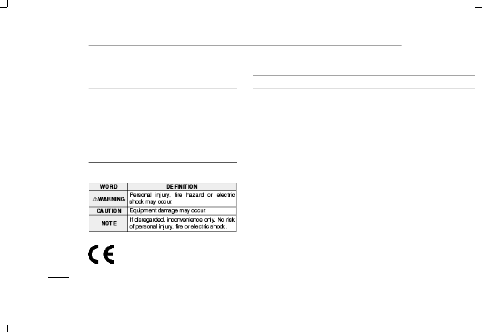
EXPLICIT DEFINITIONS
The explicit definitions below apply to this instruction manual.
CAUTIONS
RWARNING! NEVER hold the transceiver so that the
antenna is very close to, or touching exposed parts of the
b o d y, especially the face or eyes, while transmitting. T h e
transceiver will perform best if the microphone is 5 to 10 cm
(2 to 4 in) away from the lips and the transceiver is vertical.
RWARNING! NEVER operate the transceiver with a
headset or other audio accessories at high volume levels.
Hearing experts advise against continuous high volume op-
eration. If you experience a ringing in your ears, reduce the
volume or discontinue use.
NEVER connect the transceiver to an AC outlet or to a
power source of more than 16 V DC. Such a connection will
damage the transceiver.
NEVER connect the transceiver to a power source that is
DC fused at more than 5 A. Accidental reverse connection will
be protected by this fuse, higher fuse values will not give any
protection against such accidents and the transceiver will be
ruined.
NEVER attempt to charge alkaline or dry cell batteries. Be-
ware that external DC power connections will charge batteries
inside the battery case. This will damage not only the battery
case but also the transceiver.
IC-T81A/E Manual 98.12.16 4:39 PM Page ii (1,1)
iii
DO NOT push the PTT when not actually desiring to trans-
mit.
Place unit in a secure place to avoid inadvertent use by chil-
dren.
DO NOT operate the transceiver near unshielded electri-
cal blasting caps or in an explosive atmosphere.
AVOID using or placing the transceiver in direct sunlight or
in areas with temperatures below –10°C (+14°F) or above
+60°C (+140°F).
The use of non-Icom battery packs/chargers may impair
transceiver performance and invalidate the warranty.
Even when the transceiver power is OFF, a slight current still
flows in the circuits. Remove the battery pack or case from
the transceiver when not using it for a long time. Otherwise,
the battery pack or installed Ni-Cd batteries will become ex-
hausted.
For USAonly:
Caution: Changes or modifications to this transceiver, not ex-
pressly approved by Icom Inc., could void your authority to
operate this transceiver under FCC regulations.
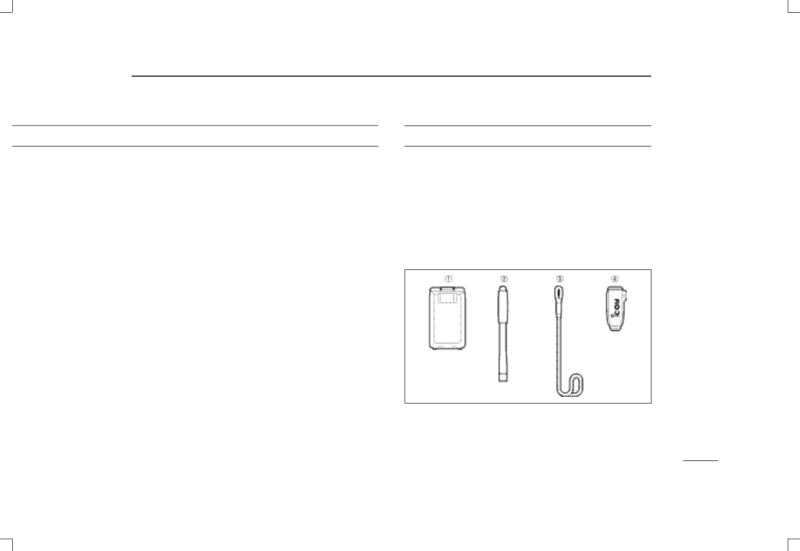
SUPPLIED ACCESSORIES
Accessories included with the transceiver:
➀Battery pack (BP-199 or BP-200) . . . . . . . . . . . . . . . . . 1
➁Antenna . . . . . . . . . . . . . . . . . . . . . . . . . . . . . . . . . . . . . 1
➂Handstrap . . . . . . . . . . . . . . . . . . . . . . . . . . . . . . . . . . . 1
➃Belt clip . . . . . . . . . . . . . . . . . . . . . . . . . . . . . . . . . . . . . 1
*Some versions are supplied with a wall charger.
IC-T81A/E Manual 98.12.16 4:39 PM Page iii (1,1)

iv
IMPORTANT ...................................................................................................ii
EXPLICITDEFINITIONS ................................................................................ii
CAUTIONS .....................................................................................................ii
SUPPLIED ACCESSORIES...........................................................................iii
TABLE OF CONTENTS .................................................................................iv
1ACCESSORYATTACHMENT...................................................................1
2PANELDESCRIPTION .........................................................................2–5
■Switches, controls, keys and connectors ...............................................2
■Function display .....................................................................................4
3BATTERYPACKS AND CHARGING ...................................................6–8
■Battery pack charging ............................................................................6
■Charging precautions.............................................................................6
■About battery packs ...............................................................................6
■Charging connections ............................................................................7
■Battery case ...........................................................................................8
4BASIC OPERATION ...........................................................................9–14
■Power ON ..............................................................................................9
■Setting a frequency ................................................................................9
■Setting tuning steps .............................................................................10
■Selecting a memory channel ................................................................11
■Lock function ........................................................................................11
■Receive and transmit ...........................................................................11
■FM broadcast reception .......................................................................12
■Air band reception................................................................................12
■Narrow FM operation ...........................................................................12
■RIT/VXOa function ...............................................................................13
■Receive mode ......................................................................................14
5REPEATER OPERATION .................................................................15–17
■General ................................................................................................15
■Subaudible tones for repeater use .......................................................16
TABLE OF CONTENTS
■Setting an offset frequency ..................................................................16
■Auto repeater function .........................................................................17
6MEMORY/CALLPROGRAMMING ...................................................18–20
■General ................................................................................................18
■Programming a memory channel.........................................................18
■Memory editing ....................................................................................19
■Memory names ....................................................................................20
7DTMF MEMORY .....................................................................................21
■Programming a DTMF code ................................................................21
■Transmitting a DTMF code ..................................................................21
8SCAN FUNCTIONS ..........................................................................22–24
■Scan types ...........................................................................................22
■Full/programmed scan .........................................................................23
■Memory (skip) scan .............................................................................23
■Skip channel setting .............................................................................24
■Scan resume condition ........................................................................24
9SUBAUDIBLE TONE OPERATION ..................................................25–26
■Tone squelch........................................................................................25
■Tone scan ............................................................................................26
■Pocket beep operation .........................................................................26
10 OTHER FUNCTIONS ........................................................................27–30
■Help function ........................................................................................27
■Initial set mode.....................................................................................27
■Resetting the CPU ...............................................................................29
■Cloning.................................................................................................30
11 TROUBLESHOOTING ............................................................................31
12 SPECIFICATIONS...................................................................................32
13 OPTIONS ................................................................................................33
14 MODE ARRANGEMENT ..................................................................34–35
IC-T81A/E Manual 98.12.16 4:39 PM Page iv (1,1)
1
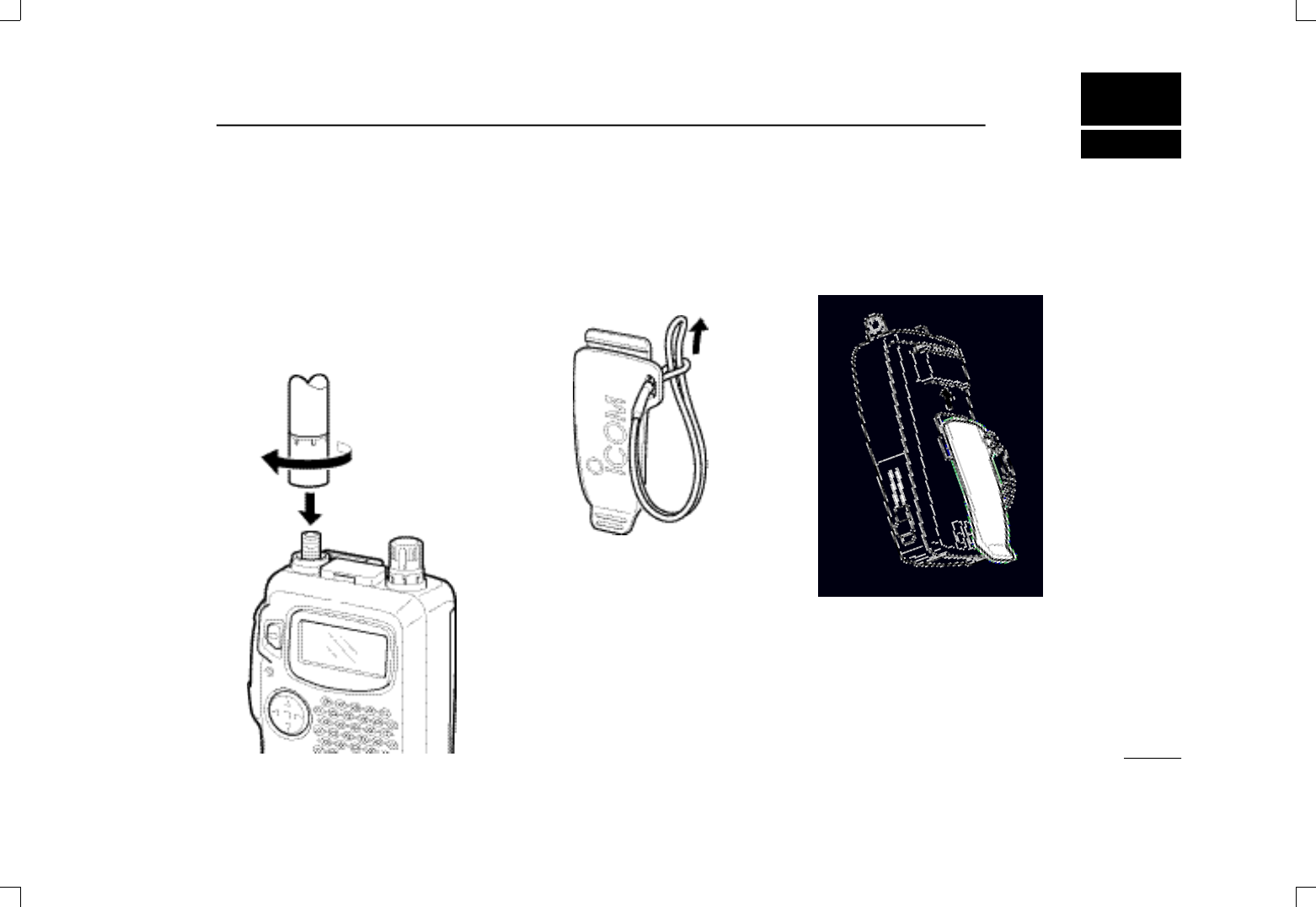
1ACCESSORY ATTACHMENT
DAntenna
Screw the supplied antenna onto the
antenna connector as shown in the dia-
gram below.
K e e p the jack cover attached when
jacks are not in use to avoid bad con-
tacts.
DHandstrap
Attach the handstrap to the belt clip, be-
fore attaching the belt clip to the trans-
ceiver, as below.
DBelt clip
Attach the belt clip to the transceiver as
illustrated below.
uCAUTION:
Transmitting
without the an-
tenna may dam-
age the
transceiver.
IC-T81A/E Manual 98.12.16 4:39 PM Page 1 (1,1)
PANEL DESCRIPTION
2
2
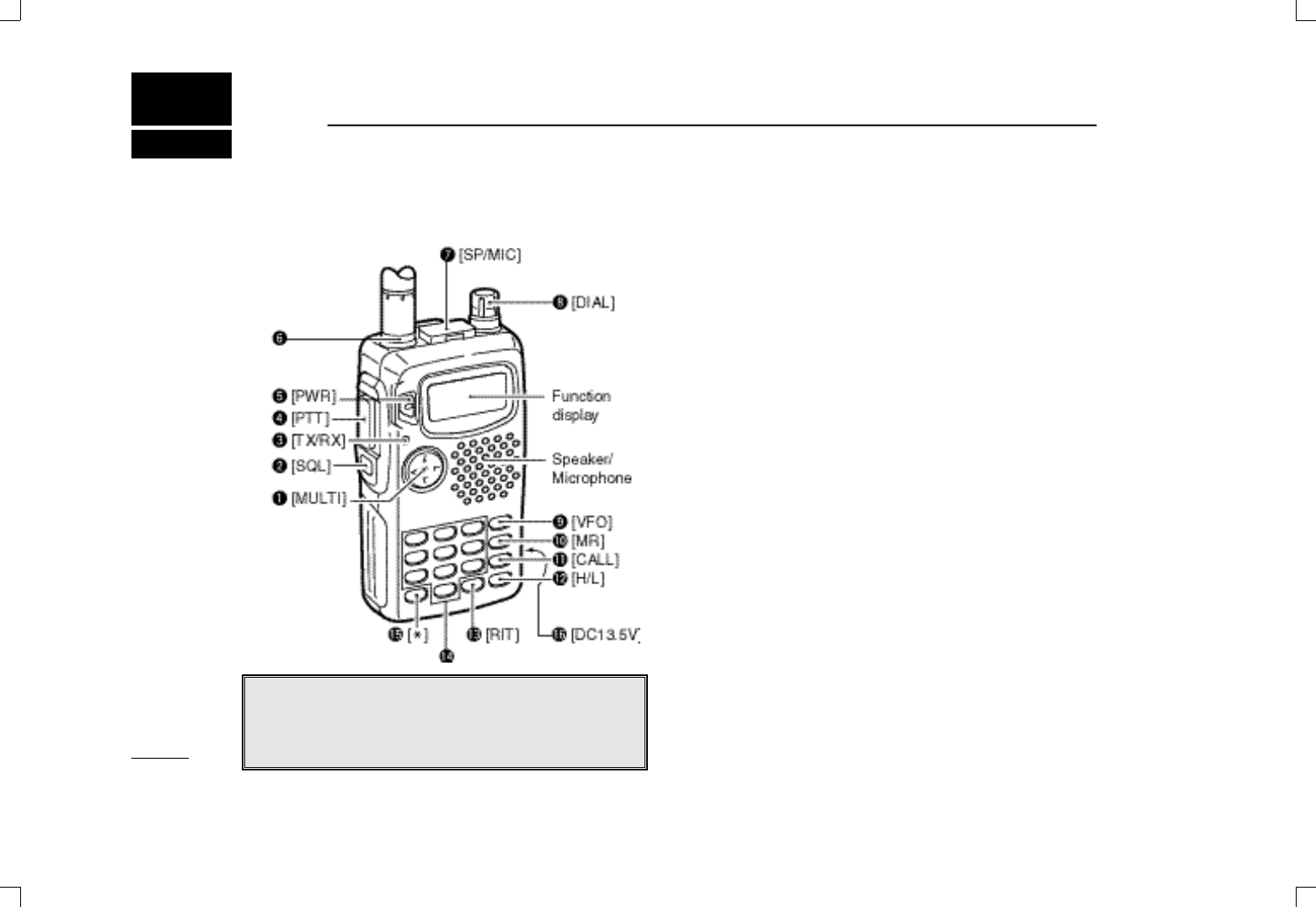
qMULTIFUNCTION SWITCH [MULTI]
➥Push to select the tone or duplex menu. (pgs. 15–17);
push for 1 sec. to enter set mode (pgs. 27–29).
➥Push ↕to increase/decrease the volume (p. 11).
➥Push ↔to change the operating band; push for 1 sec.
to start a scan (p. 23).
wSQUELCH SWITCH [SQL] (p. 11)
➥Push and hold to open the squelch.
➥While pushing, rotate [DIAL] to adjust the squelch set-
ting.
eTX/RX INDICATOR (p. 11)
Lights red while transmitting; green while receiving (or
when the squelch is open).
rPTT SWITCH [PTT] (p. 11)
Push and hold to transmit; release to receive.
tPOWER SWITCH [PWR] (p. 9)
Push for 1 sec. to turn power on and off.
yANTENNA CONNECTOR (p. 1)
Connects the supplied antenna.
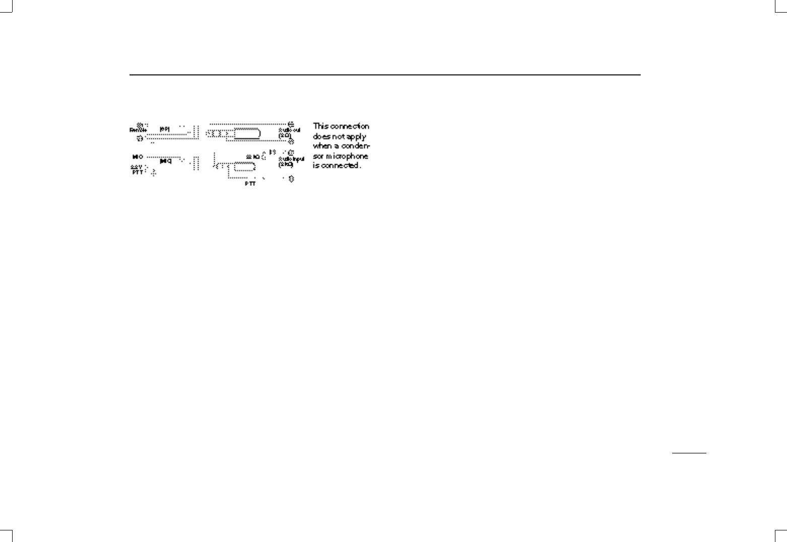
uEXTERNAL SPEAKER AND MICROPHONE JACKS
[SP/MIC]
Connect an optional speaker-microphone or headset, if de-
sired. The internal microphone and speaker will not func-
tion when either is connected. (See p. 33 for options.)
■Switches, controls, keys and connectors
NOTE: In this manual—
Push [MULTI] means push directly;
Push [MULTI(↕)] means push up or down; and
Push [MULTI(↔)] means push left or right. See q
above.
IC-T81A/E Manual 98.12.16 4:39 PM Page 2 (1,1)
3
2PANEL DESCRIPTION
☞N O T E : When connecting or disconnecting an external
speaker-microphone, first turn off power to the transceiver.
iTUNING CONTROL [DIAL]
Changes the operating frequency; memory channel in
memory mode; set mode contents in set mode, etc.
oVFO/CLEAR KEY [VFO(CLR/MHz)Å]
➥Push to select VFO mode. (p. 9)
➥Cancels some functions such as digit input before entry,
scans, etc.
➥Push and hold for 1 sec., then rotate [DIAL] to change
the MHz digit. (p. 10)
➥While pushing [PTT], this key sends a DTMF “A.” (p. 21)
!0 MEMORY MODE KEY [MR(MW)ı]
➥Push to select memory mode. (p. 11)
•“X” appears while in memory mode.
➥Push for 1 sec. to enter memory write mode. (p. 18)
➥While pushing [PTT], this key sends a DTMF “B.” (p. 21)
!1 CALL KEY [CALLÇ]
➥Push to select the call channel. (p. 19)
➥While pushing [PTT], this key sends a DTMF “C.” (p. 21)
!2 OUTPUT POWER KEY [H/L(LOCK)Î]
➥Push to toggle between low and high power. (p. 11)
•“LOW” appears while low power is selected.
➥Push for 1 sec. to toggle the lock function on/off. (p. 11)
• “L” appears while the lock function is activated.
➥While pushing [PTT], this key sends a DTMF “D.” (p. 21)
!3 RIT KEY [RIT(TSCAN)#] (p. 13)
➥Push, then rotate [DIAL] to change the RIT/VXO setting.
•This function is only available for the 1.2 GHz band and RIT
or VXO must be activated in set mode (p. 13).
➥Push for 1 sec. to turn the tone scan function on/off. (p.
26)
➥While pushing [PTT], this key sends a DTMF “F.” (p. 21)
!4 DIGIT KEYS
➥Input the specified digit during frequency input, memory
channel selection, etc.
➥Transmit the DTMF code of the specified digit while
pushing [PTT]. (p. 21)
!5 MHz KEY [• (M)] (p. 10)
➥Used as a shortcut for inputting frequencies.
➥Transmits an “E” for DTMF operation while pushing
[PTT].
!6 EXTERNAL DC POWER JACK [DC13.5V]
Allows you to operate the transceiver with a 4.5 to 16 V DC
power source using optional cables, CP-12Lor OPC-254L.
uCAUTION: DO NOT connect when a battery case is at-
tached.
IC-T81A/E Manual 98.12.16 4:39 PM Page 3 (1,1)
4
2PANEL DESCRIPTION
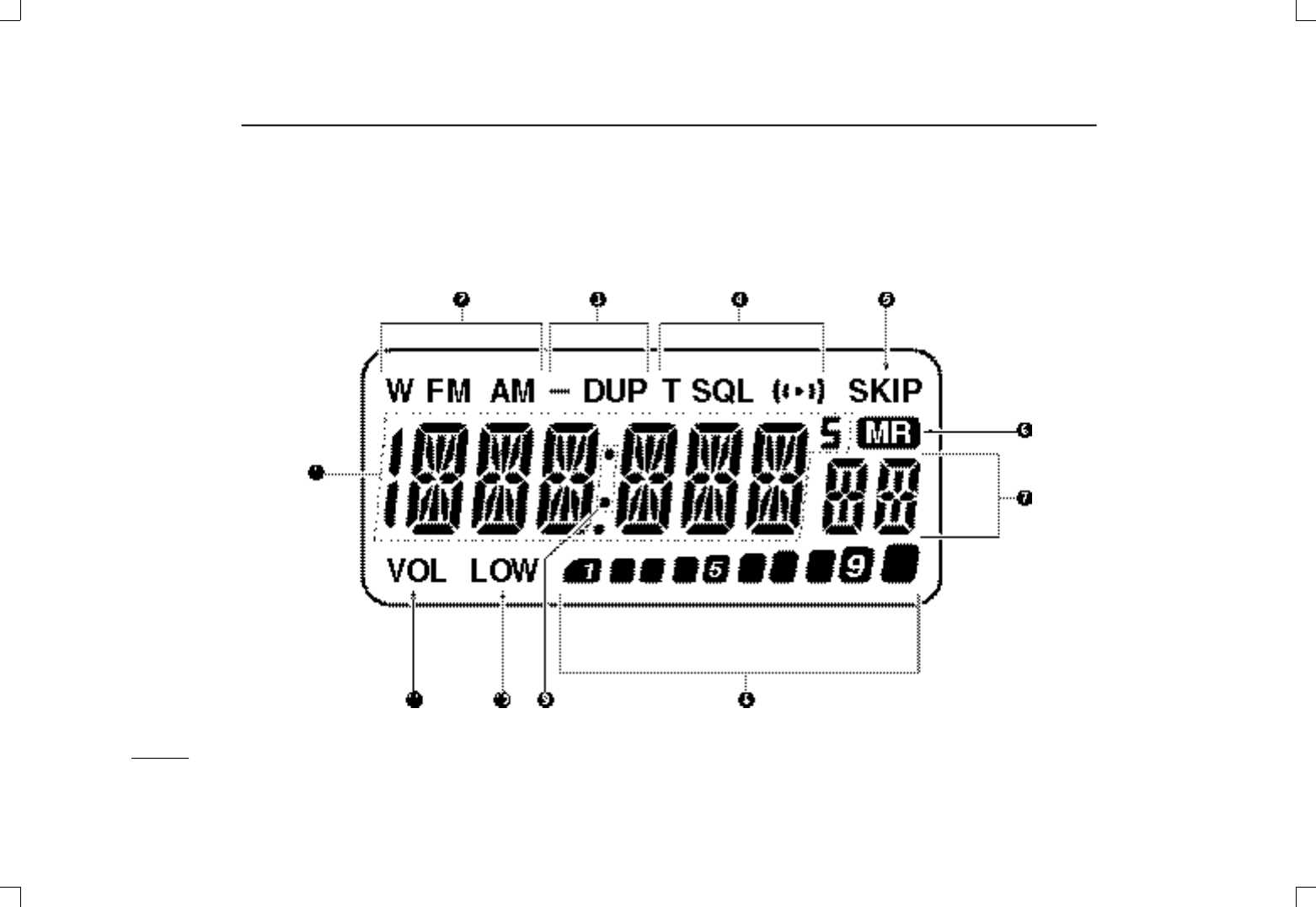
■Function display
IC-T81A/E Manual 98.12.16 4:39 PM Page 4 (1,1)

5
2PANEL DESCRIPTION
qFREQUENCY INDICATION
Shows the selected frequency, set mode contents, etc.
wMODE INDICATORS
Indicate the operating mode.
eDUPLEX INDICATOR (p. 15)
Appears during semi-duplex operation.
•“–DUP” appears for minus duplex; “DUP” appears for plus du-
plex.
rTONE INDICATORS
“T” appears when the subaudible tone encoder (p. 15) is in
use; “T S Q LS” appears during pocket beep operation
(p. 26) and “T SQL” appears when the tone squelch func-
tion (p. 25) is activated.
tSKIP INDICATOR (p. 23)
Appears when the selected channel is set as a “skip” chan-
nel.
yMEMORY MODE INDICATOR (p. 11)
Appears while in memory mode.
uMEMORY CHANNEL INDICATOR
Indicates the selected memory channel and other items
such as the call channel, set mode items, etc.
iS/RF INDICATORS (p. 11)
Show the relative signal strength while receiving and the
output power selection while transmitting.
oRIT/VXO INDICATOR (p. 13)
Appears when either the RIT or VXO function is activated
and the 1.2 GHz band is selected.
!0 LOW POWER INDICATOR (p. 11)
Appears when low output power is set.
!1 VOLUME INDICATOR
Appears while adjusting the volume.
•Indicators also appear in place of the operating frequency while
adjusting volume to visually indicate the selected volume level.
IC-T81A/E Manual 98.12.16 4:39 PM Page 5 (1,1)

6
3BATTERY PACKS AND CHARGING
■Battery pack charging
The supplied* BP-198, BP-199 or BP-200
B AT T E RY P A C K
i n-
cludes rechargeable Ni-MH batteries and can be charged ap-
prox. 300 times. Charge the battery pack before first
operating the transceiver or when the battery pack becomes
exhausted.
*Optional for versions which come with the BP-197
BATTERY CASE
.
If you want to get the longest life out of your battery pack
(300+ charges), the following points should be observed:
1. Avoid overcharging. The charging period should be less
than 15 hours.
2. Use the battery until it becomes completely exhausted
under normal conditions. We recommend battery charging
just after transmitting becomes impossible.
■Charging precautions
NEVER attempt to charge alkaline batteries. This will cause
internal liquid leakage and damage the battery case and
transceiver.
NEVER connect two or more chargers at the same time.
Charging may not occur under temperatures of 10°C (50°F)
or over temperatures of 40°C (104°F).
■About battery packs
DOperating period
Depending on attached battery pack, the operating period of
the transceiver varies. When the approx. voltage of battery
packs BP-198, BP-199 or BP-200 falls to 4, 5 or 8 V, respec-
tively, charging is necessary. Refer to p. 33 for operating pe-
riod details.
DBattery life
If your battery pack seems to have no capacity even after
being fully charged, completely discharge it by leaving the
power ON overnight. Then fully charge the battery pack
again.
If the battery pack still does not retain a charge (or very little),
a new battery pack must be purchased.
☞NOTE: When using a battery pack for the first time or after
long periods of inactivity between charges (approx. 2
months or more), the battery pack will not be able to retain
a full charge immediately. Subsequent charge/discharge
cycles will eventually bring the battery pack up to full
charge capacity.
IC-T81A/E Manual 98.12.16 4:39 PM Page 6 (1,1)
7
3BATTERY PACKS AND CHARGING
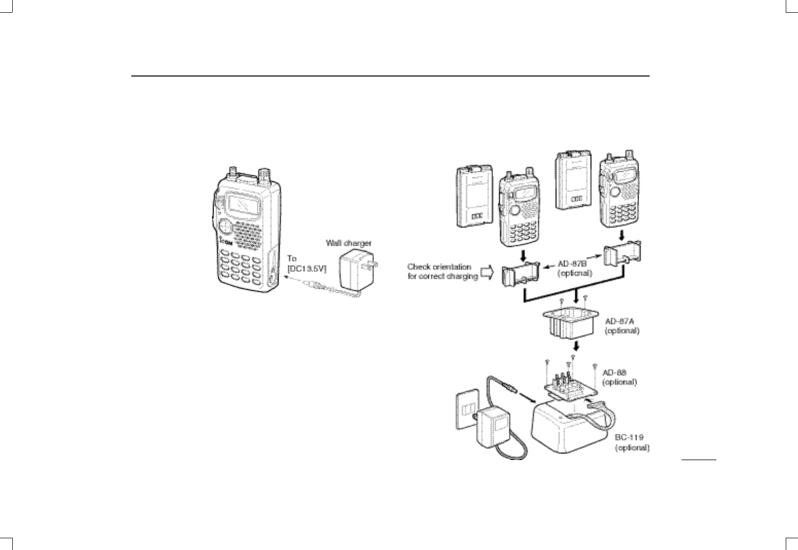
■Charging connections
DRegular charging
Attach the sup-
plied or optional
battery pack;
then, connect the
supplied* wall
charger via an AC
outlet as shown at
right.
*Optional for ver-
sions which include
a battery case.
DRapid charging with the BC-119
➀Fix the optional AD-88
T E R M I N A L P C B O A R D F O R C H A R G E R
into the BC-119 with the 4 supplied screws.
➁Insert the optional A D - 8 7 A
C H A R G EA D A P T E R
into the charg-
ing slot of the BC-119.
➂Insert the optional AD-87B
C H A R G E A D A P T E R
into A D - 8 7 A
(check orientation).
➃Insert the battery pack, either by itself or attached to the
t r a n s c e i v e r, into the whole assembly for charging (see
right).
Charging period:
15 hours
Charging periods: 1 hour (w/BP-198 or BP-199)
1.5 hours (w/BP-200)
IC-T81A/E Manual 98.12.16 4:39 PM Page 7 (1,1)
8
3BATTERY PACKS AND CHARGING
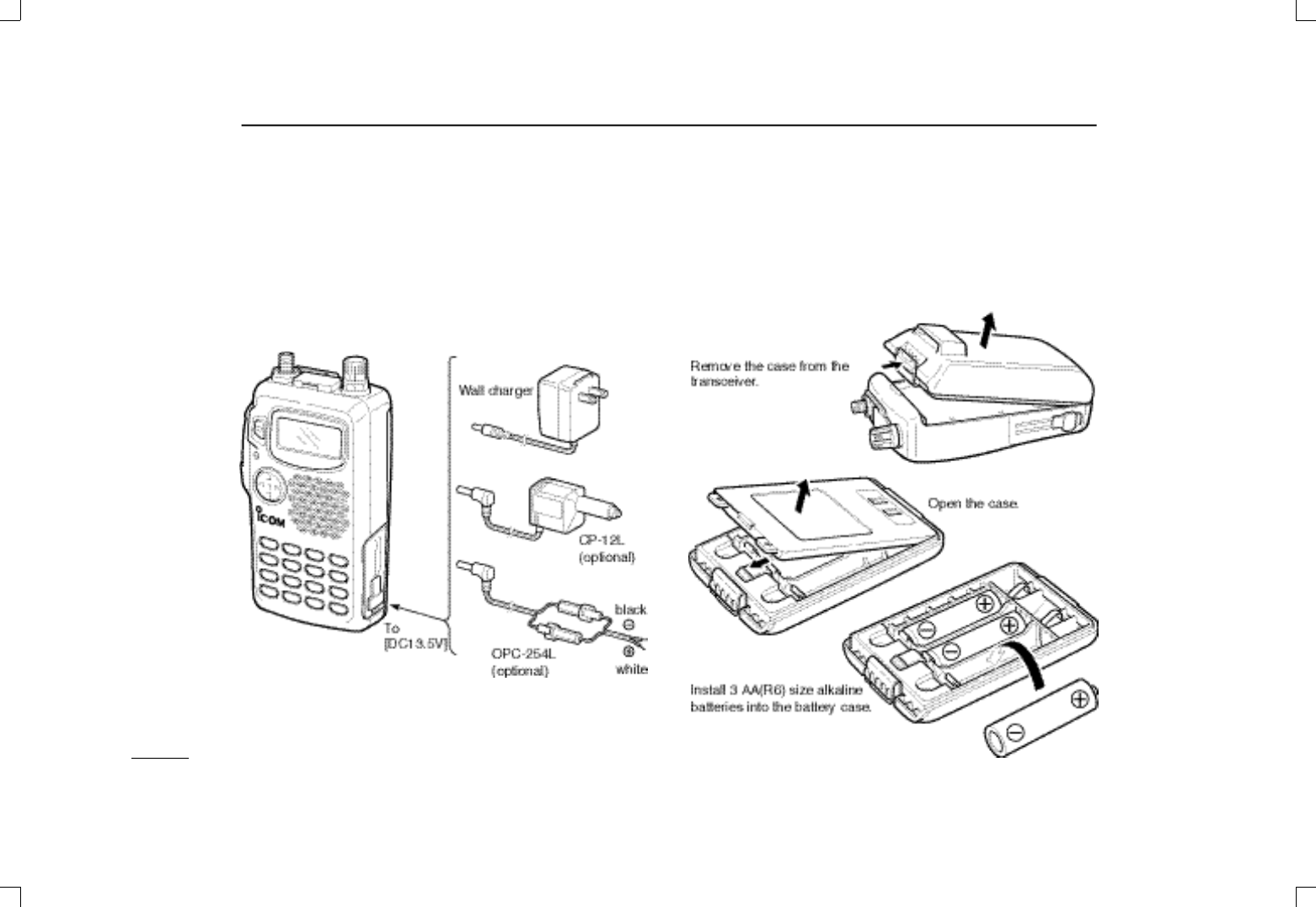
DOperation with an optional cable
Connect an optional charger or cable to the transceiver as il-
lustrated below. Be careful of battery overcharging as the
connected battery is charged simultaneously.
uC A U T I O N : When the BP-197
B AT T E RY C A S E
is con-
nected, charging cannot take place.
*To charge the battery pack
13 to 16 V DC is necessary.
■Battery case
When using a battery case attached to the transceiver, install
3 AA(R6) size alkaline batteries as illustrated below.
IC-T81A/E Manual 98.12.16 4:39 PM Page 8 (1,1)
9
4BASIC OPERATION
■Power ON
☞NOTE: Charge the battery pack before turning power on
for the first time (pgs. 6–8)
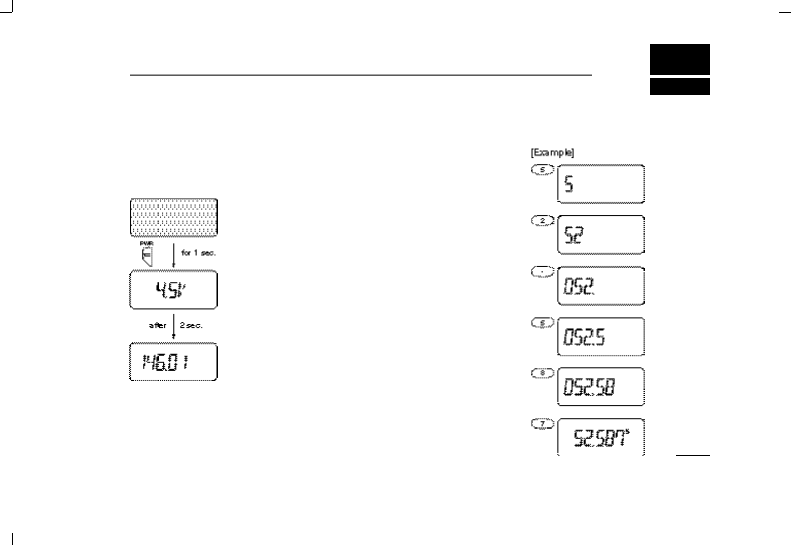
Push and hold [PWR] for 1 sec. to turn power on.
•Current battery voltage may be dis-
played for 2 sec.
•The display shows the approx. volt-
age in 0.5 V steps.
•When the battery voltage is lower
than a specified level (varies accord-
ing to battery pack used), “LOW V ”
appears. Charge the battery pack in
this case; when using a battery case
with alkaline cells this indication does
not appear.
•If “OVER V” appears, U N P L U G t h e
external DC plug immediately. Con-
nected voltage is over 16 V and could
damage the transceiver.
■Setting a frequency
DVia the keypad
(from the MHz digits)
➀Push [VFO] to select VFO
mode.
➁Push digit keys correspond-
ing to the desired frequency.
•When inputting a frequency in
the 50 MHz band, it is neces-
sary to input the decimal
point.
•When a digit is mistakenly
input, push [VFO] and input
from the beginning.
•When an unacceptable fre-
quency is input, the display re-
verts to the previously
displayed frequency.
•“0,” “2,” “5” and “7” are accept-
able as the 1 kHz digit input
depending on the 10 kHz digit.
IC-T81A/E Manual 98.12.16 4:39 PM Page 9 (1,1)
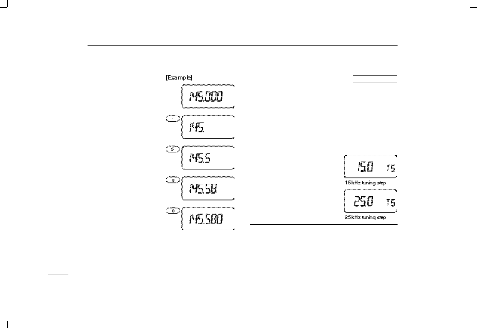
■
Setting tuning steps
The transceiver has 9 tuning steps* (each band has indepen-
dent settings) as follows:
5 kHz 10 kHz 12.5 kHz 15 kHz 20 kHz
25 kHz 30 kHz 50 kHz 100 kHz
*The 5 and 15 kHz steps are not available on the 1200 MHz band.
➀Push [VFO] to select VFO mode.
➁Push [MULTI(↔)] to select the desired band.
➂Push [MULTI] for 1 sec. to enter set mode.
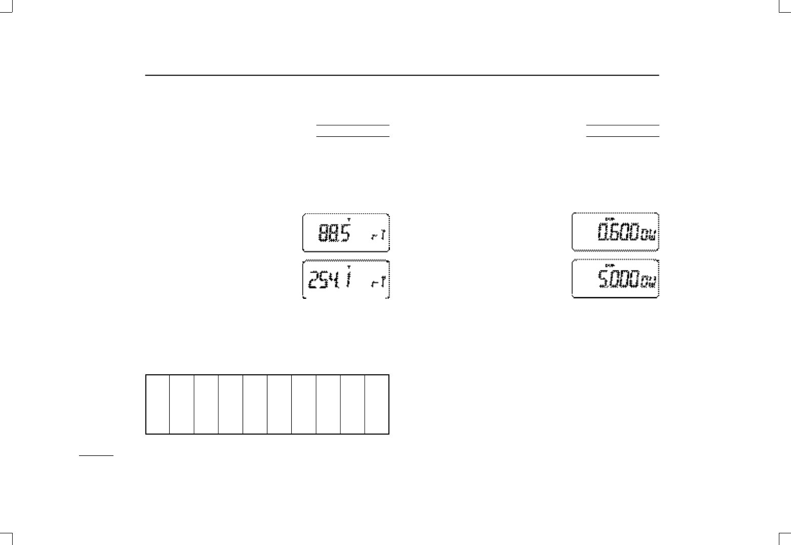
➃Push [MULTI(↕)] one or more times
until “TS” appears.
➄Push [MULTI(↔)] (or rotate [DIAL])
to select the desired tuning step.
➅Push [VFO] to exit set mode.
✔CONVENIENT
Select a tuning step that matches the frequency intervals of
repeaters in your area.
10
4BASIC OPERATION
DVia the keypad
(from the decimal point)
➀Push [VFO] to select VFO
mode.
➁Push [•] to leave the MHz
setting as is and input from
the kHz digits.
DOther methods
➥Via the [DIAL]: Rotate [DIAL] to change the frequency ac-
cording to the set tuning steps.
➥Via the MHz STEP: Push [( V F O )MHz] for 1 sec., then ro-
tate [DIAL] to change the frequency in 1 MHz steps.
USING
SET MODE
IC-T81A/E Manual 98.12.16 4:39 PM Page 10 (1,1)
11
4BASIC OPERATION
■Selecting a memory channel
➀Push [MR] to select mem-
ory mode.
➁Push [MULTI(↔)] (or rotate
[DIAL] or push digit keys) to
select the desired memory
channel.
•Only programmed memory
channels can be selected.
•Memory channels 1–9 are
preceded with a “0” when se-
lecting with the digit keys;
push “0@” to select scan edge
0A, push “0?” to select scan
edge 0B.
■Lock function
Push [(H/L)LOCK] for 1 sec. to toggle
the lock function on and off.
• “L” appears while the lock function is ac-
tivated.
•[PTT], [PWR], [MULT I (↕)] (volume), [SQL] and [H/L] can be used
even when the lock function is activated.
■Receive and transmit
➀Push [PWR] for 1 sec. to turn power on.
➁Push [MULTI(↕)] to set a volume level.
➂Set the squelch level.
•While pushing [SQL], rotate [DIAL].
•10 selections are available, “OPEN,”
“AUTO,” and “SQL1 to “SQL8.”
➃Set an operating band and frequency.
•When a signal is received:
➟Squelch opens and audio is emitted from the speaker.
➟The [TX/RX] indicator lights green.
➄Push [H/L] to toggle output power between high and low.
•“LOW” appears when low output power is selected.
➅Push and hold [PTT] to transmit; then speak into the mic.
•Do not hold the microphone too close to your mouth or speak
too loudly. This may distort the signal.
•The S/RF indicator shows the output power selection.
•The [TX/RX] indicator lights red.
➆Release [PTT] to return to receive.
✔CONVENIENT
Monitor function: Push and hold [SQL] to listen to weak sig-
nals that do not open the squelch.
IC-T81A/E Manual 98.12.16 4:39 PM Page 11 (1,1)
12
4BASIC OPERATION
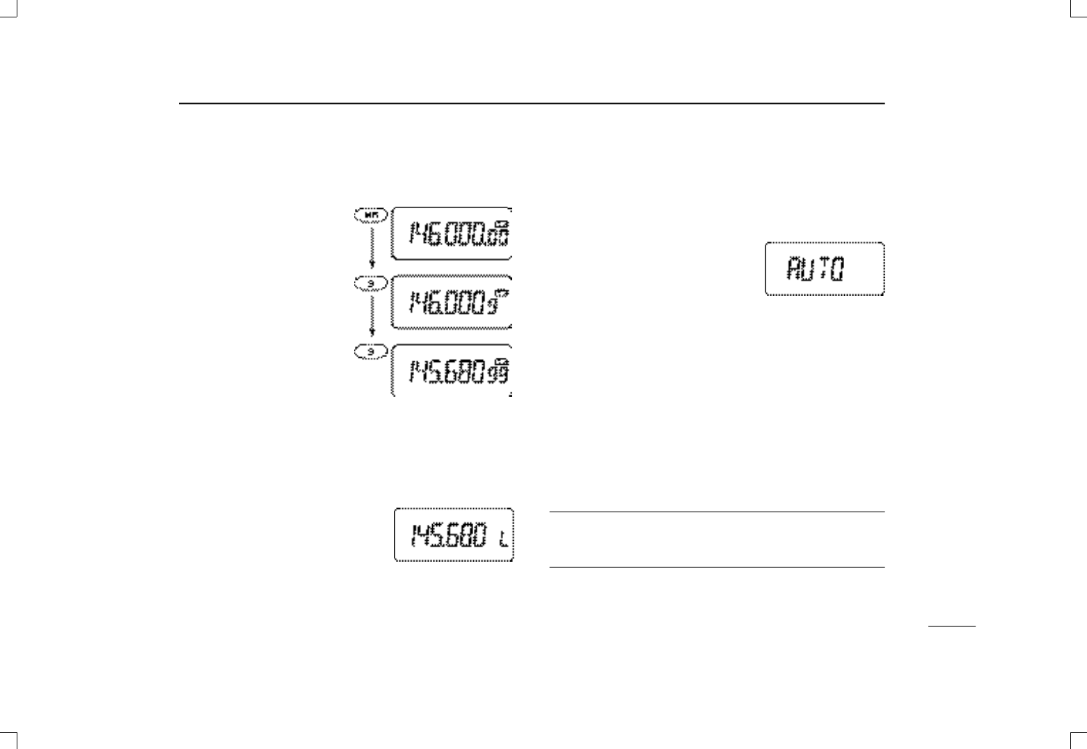
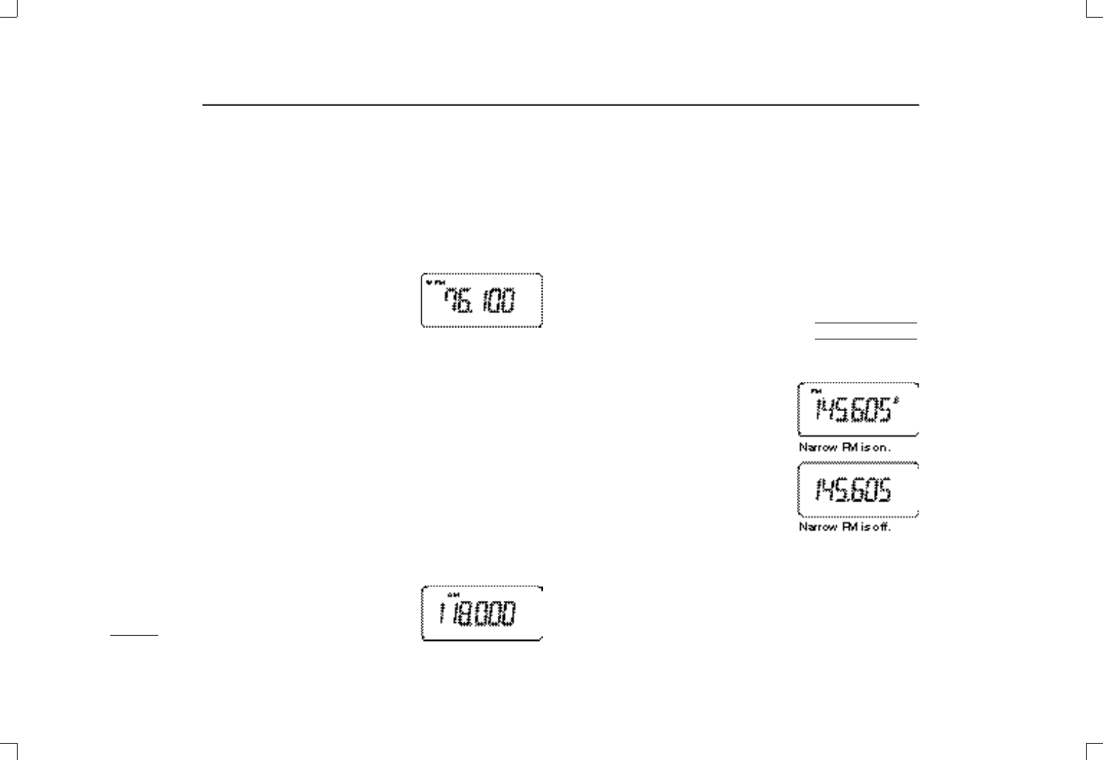
■FM broadcast reception
The transceiver can receive FM radio broadcasts. These are
typically in the range 76–107.995 MHz (88–107.995 for some
versions) and are in WFM receive mode.
To select the FM broadcast band:
➥Push [MULT I (↔)] one or more
times until “WFM” appears in the
d i s p l a y, then rotate [DIAL] to select
a frequency; or,
➥Select a frequency with the digit keys directly.
•“WFM” automatically appears when a frequency in the range
76–107.995 MHz is input.
☞N O T E : When pushing [PTT], “OFF” appears indicating the
frequency and mode are outside the permitted range.
■Air band reception (USA ver. only)
The transceiver can receive frequencies reserved for com-
mercial/private aircraft and ground support. These are in the
range 118–135.995 MHz and are in AM receive mode.
To select the air band:
➥Push [MULT I (↔)] one or more
times until “AM” appears in the dis-
play, then rotate [DIAL] to select a frequency; or,
➥Select a frequency with the digit keys directly.
•“AM” automatically appears when a frequency in the range
118–135.995 MHz is input.
☞N O T E : When pushing [PTT], “OFF” appears indicating the
frequency and mode are outside the permitted range.
■Narrow FM*
operation (Eur., France, Italy ver. only)
➀Push [MULT I (↔)] one or more
times to select the 144 MHz band.
➁Push [MULTI] for 1 sec. to enter set
mode.
➂Push [MULTI(↕)] one or more times
to display “MO,” if necessary.
➃Push [MULT I ( ↔)] (or [DIAL]) to tog-
gle narrow FM operation on and
off.
•“FM” appears when narrow FM
operation is on.
➄Push [VFO] to exit set mode and return to regular opera-
tion.
☞*N O T E : FM narrow operation can be set for individual
memory channels or in VFO mode; narrow FM aff e c t s
USING
SET MODE
IC-T81A/E Manual 98.12.16 4:39 PM Page 12 (1,1)
13
4BASIC OPERATION
■RIT/VXO function(1200 MHz band)
In the 1200 MHz band, differences between actual and dis-
played frequencies can often be large. The RIT (receive in-
cremental tuning) function allows you to compensate the
displayed frequency for differences in the actual receive fre-
quency; the VXO (variable crystal oscillator) function allows
you to compensate the displayed frequency for differences in
the actual receive and transmit frequencies.
DActivating RIT/VXO
➀Select a frequency in the 1200 MHz band (or a memory
channel with a 1200 MHz band frequency; or the 1200
MHz band call channel).
➁Push [MULTI] for 1 sec. to enter set mode.
➂Push [MULTI(↕)] one or more times until “rV” appears.
➃Push [MULT I (↔)] one or more
times to select “RIT” (RIT a c t i v a t e d ,
“VXO” (VXO activated) or “OFF”
(neither activated)—[DIAL] can
also be used.
➄Push [VFO] to exit set mode and
return to the previously selected
mode.
• When RIT or VXO is activated, “:” ap-
pears above the decimal point in the
frequency indication (in the 1200 MHz band).
USING
SET MODE
DAdjusting the frequency with RIT/VXO
Make sure that RIT or VXO is activated in set mode and that
the 1200 MHz band is selected.
➀Select a frequency in the 1200 MHz band (or a memory
channel with a 1200 MHz band frequency; or the 1200
MHz band call channel).
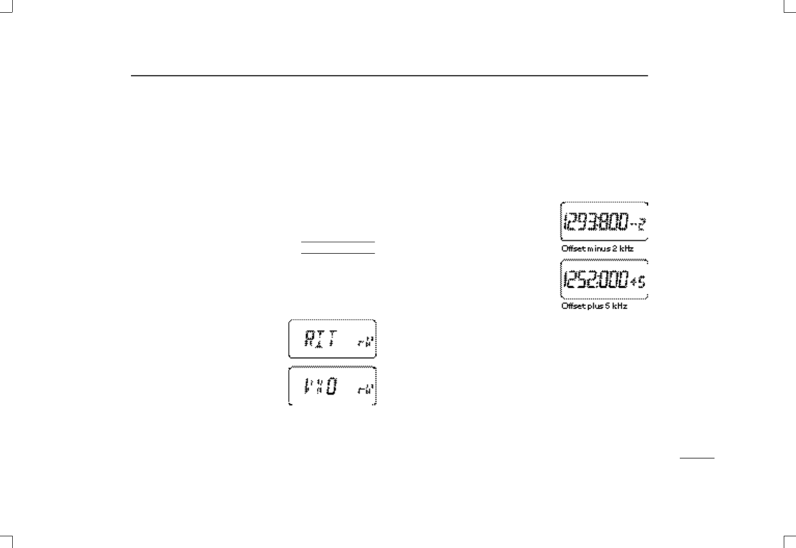
➁Push [RIT] to display the frequency
offset in kHz.
➂Push [MULT I (↔)] one or more
times (or rotate [DIAL]) to adjust
the frequency offset.
•The frequency offset can be set
±5 kHz in 1 kHz steps.
➃Push [VFO] to return to regular dis-
play indication.
IC-T81A/E Manual 98.12.16 4:39 PM Page 13 (1,1)

14
4BASIC OPERATION
■Receive mode
The IC-T81A/E allows you to receive frequencies in the 50
MHz band in AM mode (as well as to transmit in FM narrow
mode in the 144 MHz band for Italy/Europe versions only—
see p. 12).
➀Push [VFO] to select VFO mode.
➁Push [MULT I ( ↔)] one or more
times to select the 50 MHz band.
➂Push [MULTI] for 1 sec. to enter set
mode.
➃Push [MULT I (↕)] one or more times
until “MO” appears.
➄Push [MULTI(↔)] (or rotate [DIAL])
one or more times to select “AM.”
➅Push [VFO] to exit set mode and return to VFO mode.
•“AM” appears when frequencies in the 50 MHz band are se-
lected.
☞NOTE:
➥When AM operation is selected, transmit is not possible.
When [PTT] is pushed, “OFF” appears.
➥AM operation can also be selected for individual mem-
ory channels programmed with 50 MHz frequencies. In
this way you can program individual frequencies for AM
receive while allowing regular transmit/receive for 50
MHz frequencies in VFO mode.
USING
SET MODE
IC-T81A/E Manual 98.12.16 4:39 PM Page 14 (1,1)

15
5REPEATER OPERATION
■General
When using a repeater, the transmit frequency is shifted from
the receive frequency by the offset frequency. It is convenient
to program repeater info into memory channels (pgs. 18–20).
➀Set the operating band and receive frequency (repeater
output frequency).
➁Push [MULTI] to enter duplex set mode.
• “D” appears; if “T” appears instead of “D” push [MULTI(↕)] to se-
lect “D.”
➂Push [MULT I (↔)] (or rotate [DIAL]) one or more times to
select DUP ( plus duplex) or –DUP (minus duplex).
•When the auto repeater function is in use (USAversion only) this
selection and steps ➃and ➄are not necessary (p. 17).
➃Push [MULTI(↕)] to select tone set mode.
•“T” appears.
➄Push [MULT I (↔)] (or rotate [DIAL]) to activate the sub-
audible tone encoder according to repeater requirements.
•Refer to the table of subaudible tone frequencies on the following
page.
➅Push and hold [PTT] to transmit.
•The displayed frequency automatically changes to the transmit
frequency (repeater input frequency).
•If “OFF” appears, check the offset frequency (p. 16).
➆Release [PTT] to receive.
➇Push and hold [SQL] to check whether the other station’s
transmit signal can be directly received or not.
DTone information
Some repeaters require a tone to be accessed. In this case,
precede step ➅at left with the required tone.
DTMF TONES
While pushing [PTT], push the desired digit key(s) to transmit
DTMF tones.
•The transceiver has 9 DTMF memory channels. See p. 21 for de-
tails.
1750 Hz TONE
While pushing [PTT], push and hold [MULTI] for 1 to 2 sec.
to transmit a 1750 Hz tone signal.
✔Convenient
Tone scan function: When you don’t know the subaudible
tone used for a repeater, the tone scan is convenient for de-
tecting the tone frequency.
Push [(RIT)TSCAN)] for 1 sec. to activate the tone scan. See
p. 26 for more details.
IC-T81A/E Manual 98.12.16 4:39 PM Page 15 (1,1)
16
5REPEATER OPERATION
■Subaudible tones
for repeater use
Some repeaters require subaudible tones to be accessed.
Subaudible tones are superimposed over your normal signal
and must be set in advance.
➀Push [VFO] to select VFO mode.
➁Push [MULTI(↔)] to select a band.
➂Push [MULTI] for 1 sec. to enter set
mode.
➃Push [MULTI(↕)] one or more times
until “rT” appears.
➄Push [MULTI(↔)] (or rotate (DIAL)
to select the desired subaudible
tone.
➅Push [VFO] to enter the selected tone and exit set mode.
Available subaudible tone frequencies (unit: Hz)
67.0 79.7 94.8 110.9 131.8 156.7 171.3 186.2 203.5 229.1
69.3 82.5 97.4 114.8 136.5 159.8 173.8 189.9 206.5 233.6
71.9 85.4 100.0 118.8 141.3 162.2 177.3 192.8 210.7 241.8
74.4 88.5 103.5 123.0 146.2 165.5 179.9 196.6 218.1 250.3
77.0 91.5 107.2 127.3 151.4 167.9 183.5 199.5 225.7 254.1
USING
SET MODE ■Setting an offset
frequency
When communicating through a repeater, the transmit fre-
quency is shifted from the receive frequency by an amount
determined by the offset frequency.
➀Push [VFO] to select VFO mode.
➁Push [MULTI(↔)] to select a band.
➂Push [MULTI] for 1 sec. to enter set
mode.
➃Push [MULT I (↕)] one or more times
until “OW” appears.
➄Push [MULTI(↔)] (or rotate (DIAL)
to select the desired offset.
•The offset frequency changes according to the selected tuning
steps.
•The MHz step may be helpful for large frequency changes—push
[(VFO)MHz] for 1 sec.
➅Push [VFO] to enter the selected offset and exit set mode.
USING
SET MODE
IC-T81A/E Manual 98.12.16 4:39 PM Page 16 (1,1)
17
5REPEATER OPERATION
■Auto repeater
function (USAversion only)
The USAversion automatically activates the repeater settings
(duplex, ON/OFF, duplex direction, tone encoder ON/OFF)
when the operating frequency falls within or outside of the
general repeater output frequency range. The offset and re-
peater tone frequencies are not changed by the auto repeater
function, reset these frequencies, if necessary.
➀While pushing [MULTI], push
[PWR] to turn power on and enter
initial set mode.
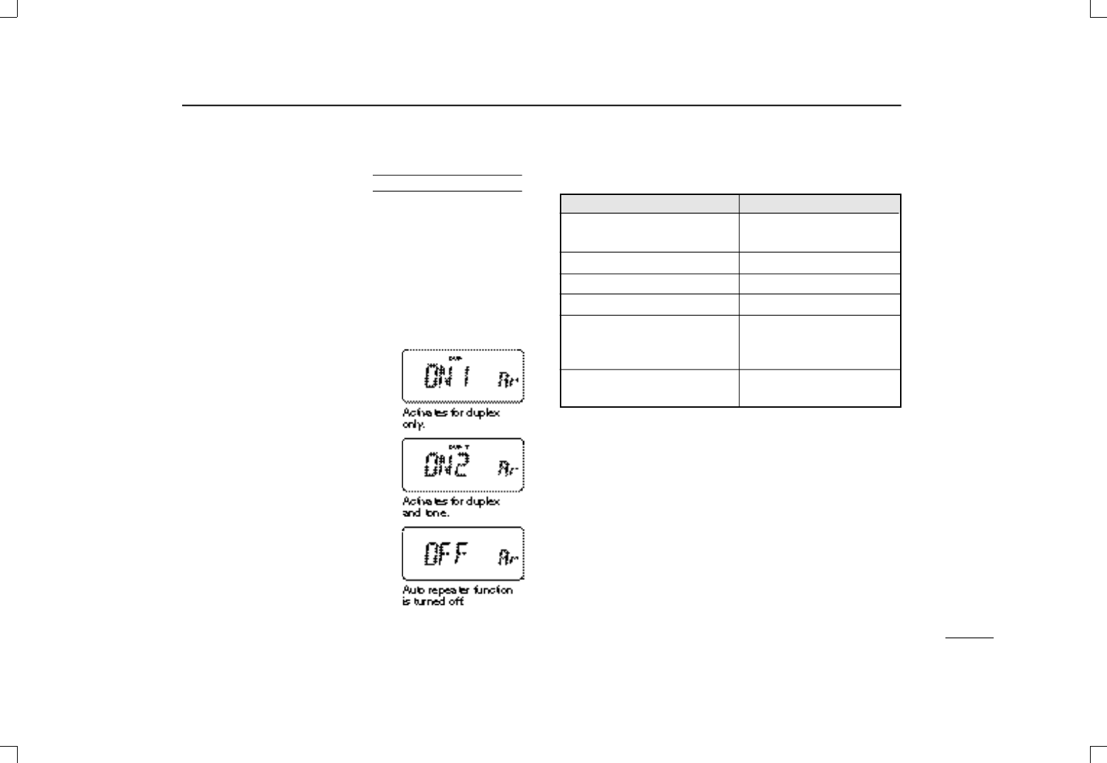
➁Push [MULT I (↕)] one or more times
until “Ar” appears.
➂Push [MULTI(↔)] (or rotate [DIAL]
to select the desired condition.
•“OFF”—the auto repeater function is
turned off;
“ON1”—the auto repeater function ac-
tivates for duplex only;
“ON2”—the auto repeater function ac-
tivates for duplex and tone.
➃Push [VFO] to exit initial set mode.
USING
INITIAL SET MODE Frequency range and offset direction
FREQUENCYRANGE DUPLEX DIRECTION
145.200– 145.495 MHz “–DUP” appears
146.610– 146.995 MHz
147.000– 147.395 MHz “DUP” appears
442.000– 444.995 MHz “DUP” appears
447.000– 449.995 MHz “–DUP” appears
51.620– 51.980 MHz
52.500– 52.980 MHz “–DUP” appears
53.500– 53.980 MHz
1282.000–1287.995 MHz* “–DUP” appears
1288.000–1295.995 MHz
*When operating in this range, the offset frequency must be set to
–12 MHz (see previous page for setting an offset).
IC-T81A/E Manual 98.12.16 4:39 PM Page 17 (1,1)

18
6MEMORY/CALL PROGRAMMING
■General
The transceiver has 124 memory channels (100 regular, 10
pairs of scan edge channels for mixed bands and 1 call chan-
nel for each band—VHF, UHF, 50 MHz and 1200 MHz). Note
that memory channels are not grouped according to band. In
other words, a given memory channel can be programmed
with either a VHF frequency, a UHF frequency, a 50 MHz fre-
quency or a 1200 MHz frequency. This is not the case with
call channels. Call channels are band specific.
The following can be programmed into memory/call channels:
•Operating frequency
• Duplex direction with an offset frequency (pgs. 15, 16)
• Subaudible tone encoder or tone squelch on/off with a tone
(CTCSS) frequency (pgs. 25, 26)
•Subaudible tone and tone squelch frequencies (pgs. 16, 25)
• Mode—AM, FM, etc. (p. 14)
• Skip information* (p. 23)
*Except for scan edge memory channels and call channels.
☞NOTE:
➥Memory channels can be assigned names (of up to 6
characters).
➥When memory names are assigned, each push of [MR]
toggles between frequency and name indication.
■Programming a memory
channel
➀Push [VFO] to select VFO mode.
➁Set the desired frequency:
➥Set other data, such as repeater
information, if required.
➂Push [(MR)MW] for 1 sec.
•“X” and the previously selected
memory channel flash.
➃Push [MULTI(↔)] (or rotate [DIAL])
to select the desired memory chan-
nel.
• Call channels and scan edge
channels, as well as regular chan-
nels, can be programmed in this
way.
•Only the decimal point appears
for memories not yet pro-
grammed.
•If you want to confirm the VFO frequency, push [MR] mo-
mentarily—the VFO frequency briefly appears.
➄Push [(MR)MW] for 1 sec. to program.
• “X” and the memory channel number stop flashing.
• VFO mode is selected.
IC-T81A/E Manual 98.12.16 4:39 PM Page 18 (1,1)
19
6MEMORY/CALL PROGRAMMING
■Memory editing
Memory (call) channel contents can be moved to VFO or to
another memory.
DTransferring a memory (call) channel’s
contents
➀Select the memory (call) channel to
be transferred:
➥Push [MR] ([CALL)]) to select
memory (call) mode.
➥Push [MULT I (↔)] (or rotate
[DIAL]) to select the memory
(call) channel.
➁Push [(MR)MW] for 1 sec.
•“VF” appears and flashes with “X”
and the previously selected VFO fre-
quency appears..
To transfer the contents to VFO:
➂Push [(MR)MW] for 1 sec.
•The contents are transferred and VFO mode is selected.
To transfer the contents to another memory (call) channel:
➂Push [MULT I (↔)] (or rotate [DIAL]) to select the memory
(call) channel to be transferred to.
➃Push [(MR)MW] for 1 sec.
•The contents are transferred and memory (call) mode is selected.
DClearing a memory
➀Push [MR] to select memory mode.
➁Push [MULTI(↔)] (or rotate [DIAL]) to select a channel to
be cleared.
➂Push [VFO] to select VFO mode.
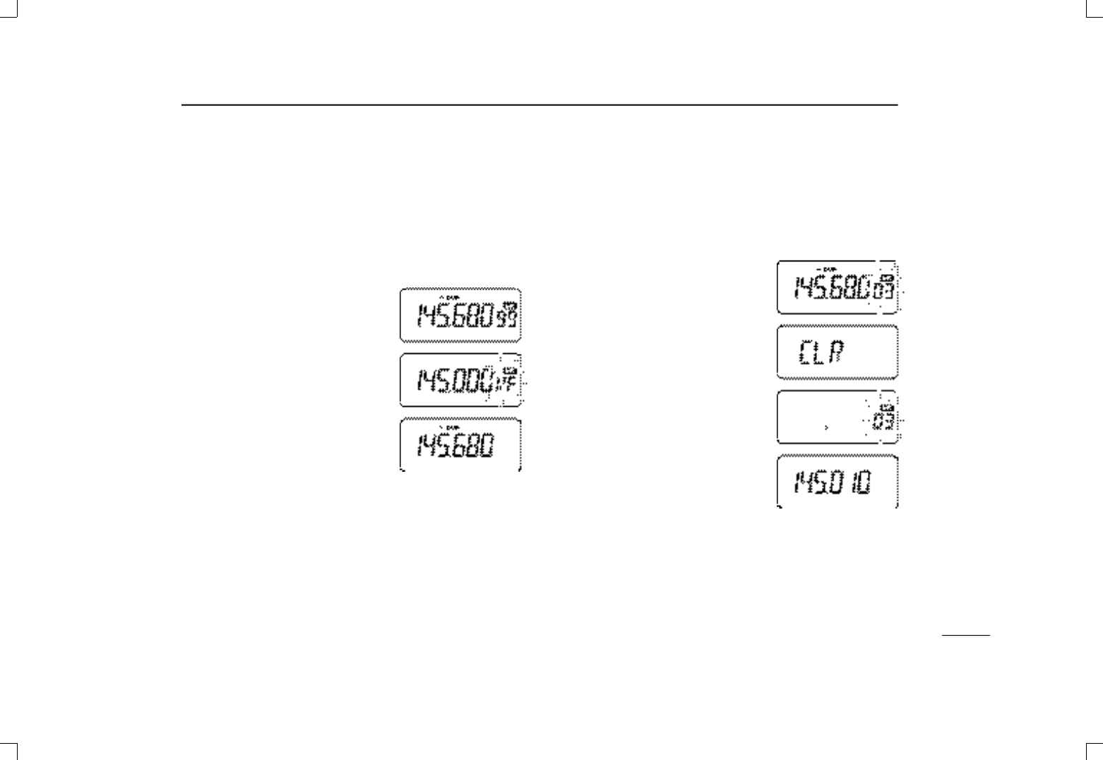
➃Push [( M R )MW] for 1 sec. to enter
memory menu mode.
•“X” and a memory channel number
flash.
➄Push [MULTI(↕)] to display “CLR.”
•Scan edge channels 0A/0B and call
channels cannot be cleared.
➅Push [( M R )MW] for 1 sec. to clear
the previously selected memory
channel.
•“X” and a memory channel number
flash and the previously stored infor-
mation is erased.
➆Push [VFO] to select return to VFO
mode.
☞N O T E : Be careful—the contents of cleared memories c a n-
not be recalled.
IC-T81A/E Manual 98.12.16 4:40 PM Page 19 (1,1)
20
6MEMORY/CALL PROGRAMMING
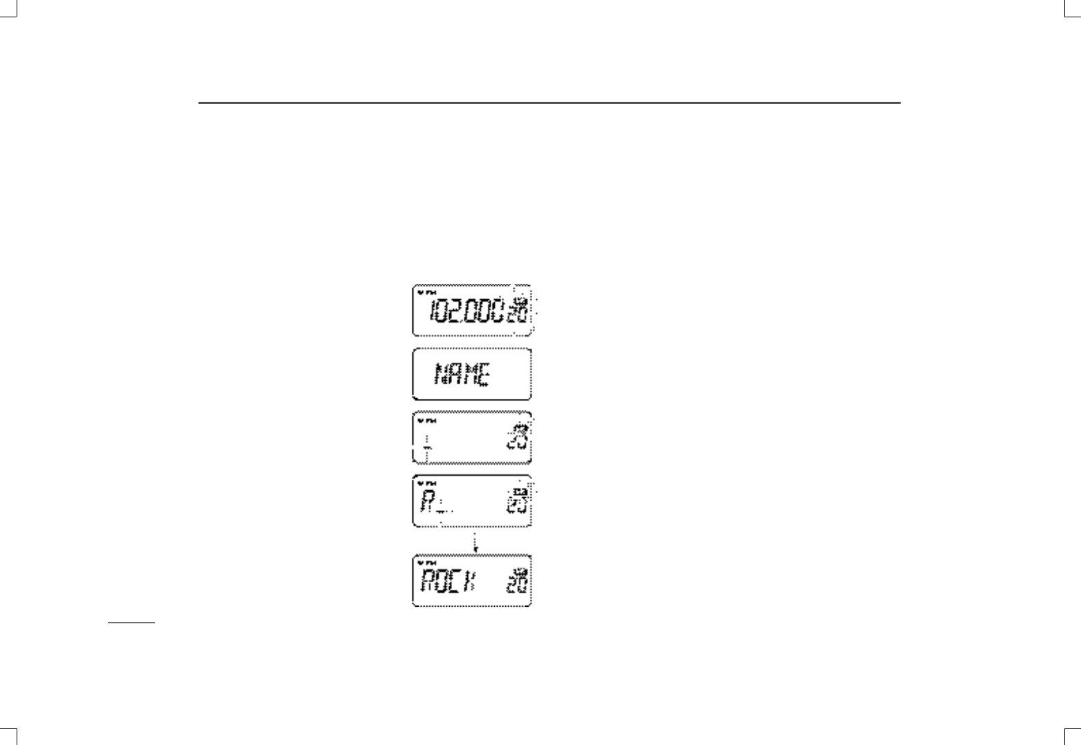
■Memory names
Memory channels can be programmed with names of up to
six characters.
➀Push [VFO] to select VFO mode (or select a memory chan-
nel).
➁Push [(MR)MW] for 1 sec.
•“X” and the previously selected
memory channel number flash.
➂Push [MULTI(↔)] (or rotate [DIAL])
to select the desired memory chan-
nel.
➃Push [MULT I (↕)] so that “NAME”
appears.
•Not valid for call channels.
➄Push [MULTI] to enter name editing
mode.
•The first character of the name fla s h e s .
➅Rotate [DIAL] (or push [MULT I (↕) ]
to select a character; then, push
[MULTI(↔)] to advance to the next
character.
➆Repeat step ➅until the desired
name appears.
➇Push [MULTI] to program the name
and return to the “NAME” display;
then push [VFO] to return to VFO
mode.
• Push [(MR)MW] for 1 sec. to erase a channel’s name and return
to VFO mode.
•When in memory mode push [MR] to toggle between memory
name indication and frequency indication.
☞NOTE: To clear a memory name (or remove one or more
characters from a name) without clearing the rest of the
memory channel contents, follow steps ➀to ➇at left and
insert an underscore “_” in place of other characters in
steps ➅and ➆.
IC-T81A/E Manual 98.12.16 4:40 PM Page 20 (1,1)
21
7DTMF MEMORY
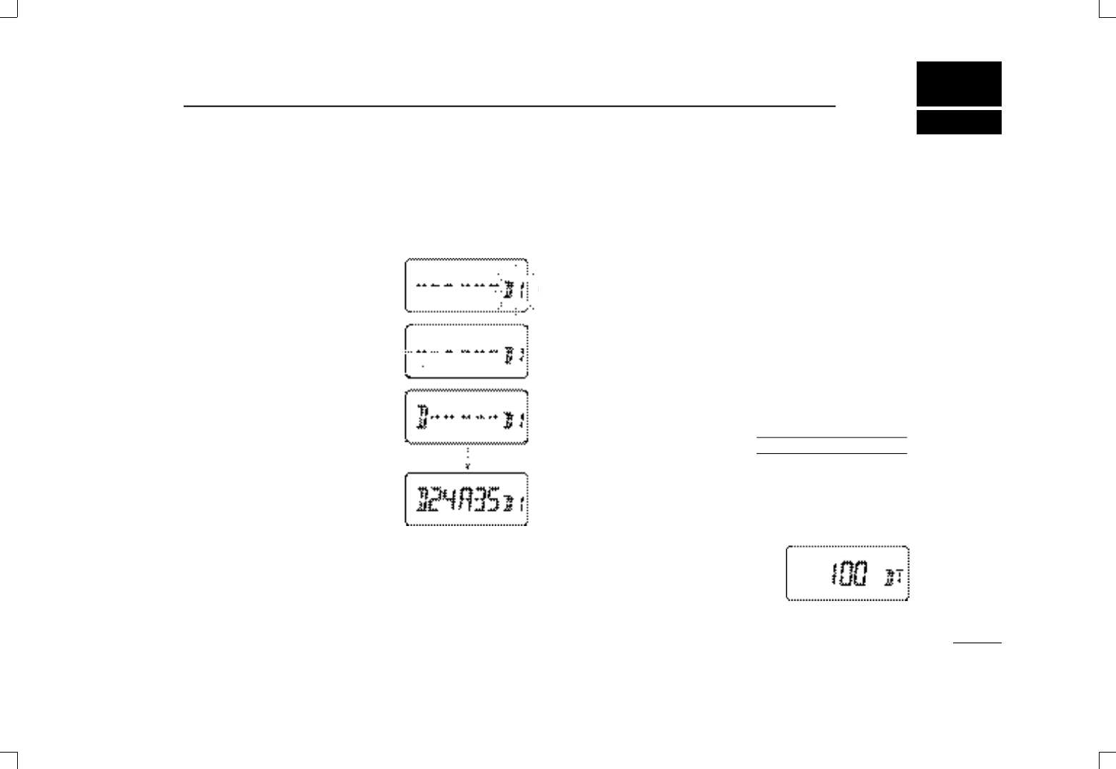
■Programming a DTMF code
The transceiver has 9 DTMF memory channels (D1 to D9) for
storage of often-used DTMF codes of up to 16 characters.
➀Push [( M R )MW] for 1 sec. to enter
memory write mode; then push
[MULTI(↕)] to enter DTMF memory
mode.
•One of “D1” to “D9” appears and
flashes.
➁Rotate [DIAL] (or push [MULT I (↔) ] )
to select the desired channel.
➂Push [MULTI] to enter DTMF pro-
gramming mode.
•The first character of the DTMF code
flashes.
➃Push digit keys (or rotate [DIAL] or
push [MULT I (↕)]) to enter the de-
sired DTMF character; then push
[MULTI(↔)] to advance to the next
character.
•Amaximum of 16 characters can be input.
•Pushing [MULTI(↕)] can also be used to enter DTMF characters.
•When pushing [SQL], the programmed contents can be moni-
tored.
➄Push [MULTI] to input the digits; then push [VFO] to exit
DTMF programming mode.
■Transmitting a DTMF code
DUsing a DTMF memory channel
➀Push [( M R )MW] for 1 sec. to enter memory write mode;
then push [MULTI(↕)] to enter DTMF memory mode
•One of “D1” to “D9” appears.
➁Rotate [DIAL] (or push [MULT I (↔)]) to select the desired
channel.
➂While pushing [PTT], push [SQL] to transmit the selected
DTMF channel’s contents.
DManual DTMF code transmission
➀While pushing [PTT], push digit keys to transmit a DTMF
code manually.
➁Release [PTT] to return to receive.
DDTMF transmit speed
When slow DTMF transmission speeds are required (such as
for some repeaters) the transceiver’s rate of DTMF transmis-
sion can be adjusted.
➀While pushing [MULTI], push [PWR] to turn power on and
enter initial set mode.
➁Push [MULT I (↕)] one or more times
until “DT” appears.
➂Rotate [DIAL] (or push [MULT I (↔) ] )
to select the a transmit speed.
•100 (default), 200, 300 and 500 msec. are available.
➃Push [VFO] to exit initial set mode.
USING
INITIAL SET MODE
IC-T81A/E Manual 98.12.16 4:40 PM Page 21 (1,1)
22
8SCAN FUNCTIONS
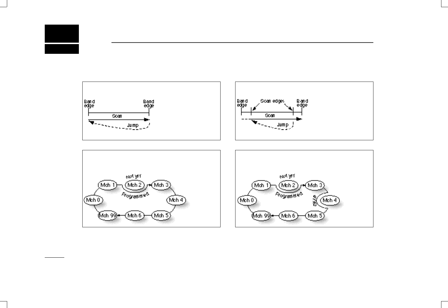
■Scan types
FULL SCAN (p. 23)
PROGRAMMED SCAN (p. 23)
MEMORY SCAN (p. 23
MEMORY SKIP SCAN (p. 23)
☞NOTE: Push [MULTI(↔)] during full/programmed scan to
change the band being scanned or to select a different pair
of scan edges.
Push [MULT I (↔)] during memory (skip) scan to change the
memory channel groups: 1.2 GHz, VHF, UHF, 50 MHz, air
band or WFM programmed memories; or, all programmed
memories.
Repeatedly scans all fre-
quencies over a selected
band.
Repeatedly scans all pro-
grammed memory chan-
nels.
Repeatedly scans be-
tween two user-pro-
grammed frequencies.
Used for checking for fre-
quencies within a speci-
fied range such as
repeater output frequen-
cies.
Repeatedly scans all
memories, except those
set as skip channels.
IC-T81A/E Manual 98.12.16 4:40 PM Page 22 (1,1)

23
8SCAN FUNCTIONS
■Full/programmed scan
➀Push [VFO] to select VFO mode, if necessary.
➁Push [MULT I (↔)] for 1 sec. to start the scan; after that,
each push of [MULTI(↔)] selects a different scan range.
•To change the scan direction, rotate [DIAL].
➥The following scan ranges are selectable:
•“ALL50” for full scan on the 50 MHz band.
•“ALL144” for full scan on the 144 MHz band.
•“ A L L 430” or “ALL 440” for full scan on the 430(440) MHz
band.
•“ALL WFM” for full scan on the WFM (FM broadcast) band.
•“ALL 118” for full scan on the air band.
•“ALL1200” for full scan on the 1.2 GHz band.
•“PROG 0” to “PROG 9” for one of the programmed scans.
➂To stop the scan, push [VFO].
☞N O T E : For programmed scan, scan edges must be pro-
grammed in advance (0A/0B are programmed by default).
Program scan edges in the same manner as regular mem-
ory channels (p. 18).
If the same frequencies are programmed into a pair of scan
edges, programmed scan does not proceed.
■Memory (skip) scan
➀Push [MR] to select memory mode, if necessary.
➁Push [MULT I (↔)] for 1 sec. to start the scan; after that,
each push of [MULTI(↔)] selects a different scan group.
•To change the scan direction, rotate [DIAL].
➥The following memory groups are selectable:
•“SELALL” scans all programmed memory channels.
•“SEL50” scans programmed memories in the 50 MHz band.
•“ S E L 144” scans programmed memories in the 144 MHz
band.
•“SEL430” or “SEL440” scans programmed memories in the
430(440) MHz band.
•“SELWFM” scans all programmed WFM channels.
•“SEL118” scans all programmed air band channels.
•“ S E L 1200” scans programmed memories in the 1.2 GHz
band.
➂To stop the scan, push [VFO].
☞N O T E : For memory skip scan, program memory channels
you don’t want to search, as “skip” channels (p. 24). Scan
proceeds as above except that any channels specified as
skip channels are not searched.
IC-T81A/E Manual 98.12.16 4:40 PM Page 23 (1,1)
24
8SCAN FUNCTIONS
■Skip channel setting
Memory channels can be set to be skipped during memory
scan. This is useful to speedup the memory scan interval.
➀Push [MR] to select memory mode.
➁Push [(MR)MW] for 1 sec. to enter memory write mode.
➂Rotate [DIAL] (or push [MULT I (↔)]) to select a memory
channel.
➃Push [MULTI(↕)] twice times to select “SKIP.”
➄Push [MULTI(↔)] (or rotate [DIAL])
to toggle the skip setting for the se-
lected channel ON/OFF.
•“SKIP” appears when the channel is
set as a skip channel.
➅Push [VFO] to program the setting
and exit memory write mode.
☞N O T E : Scan edge channels, 0A to 9B, cannot be set to
show “SKIP” settings, however, they will be skipped dur-
ing scan.
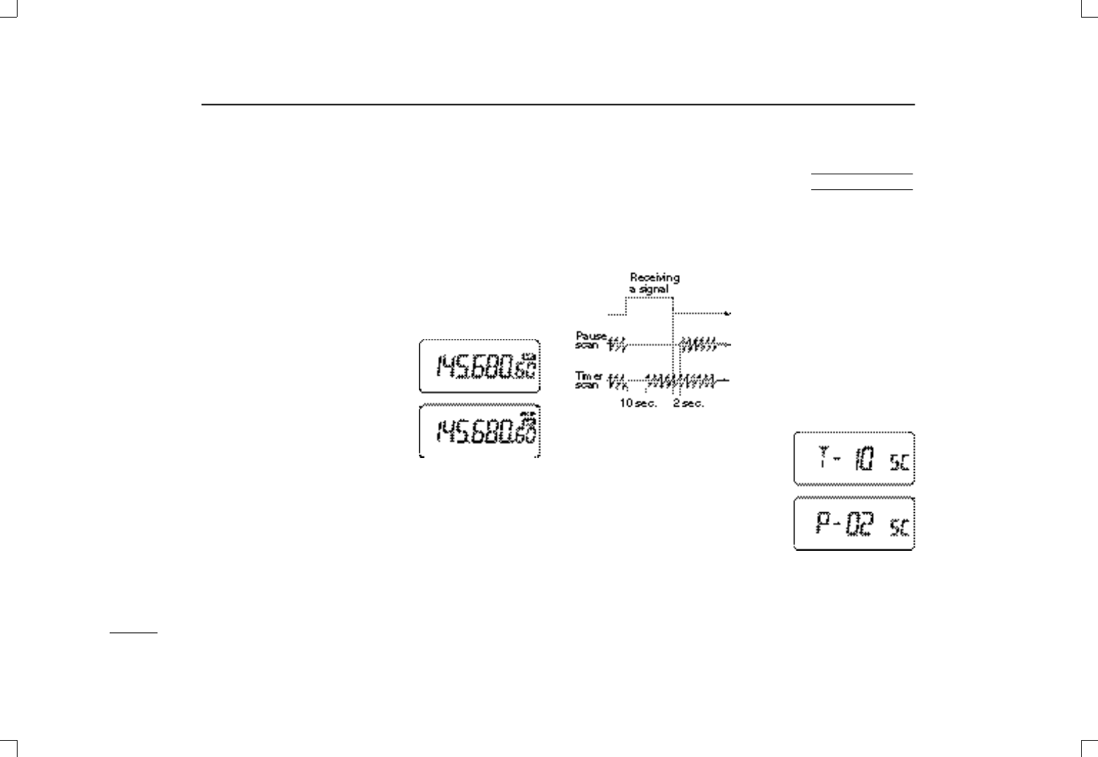
■Scan resume
condition
The resume condition can be selected as a pause or timer
scan. This setting is common for all scans.
USING
SET MODE
When receiving a signal, pause
scan pauses until the signal dis-
appears; timer scan pauses for
10 sec.
➀Push [MULTI] for 1 sec. to enter set
mode.
➁Push [MULTI(↕)] one or more times
until “SC” appears.
➂Push [MULTI(↔)] (or rotate [DIAL])
to select the desired scan resume
condition.
•“ T-10”: scan pauses for 10 sec. on a
received signal.
•“P-02”: scan pauses on a received signal until it disappears.
➃Push [VFO] to exit set mode.
IC-T81A/E Manual 98.12.16 4:40 PM Page 24 (1,1)

25
9SUBAUDIBLE TONE OPERATION
■Tone squelch
The tone squelch opens only when receiving a signal con-
taining a matching subaudible tone. You can silently wait for
calls from group members using the same tone.
➀Set the operating frequency.
➁Set the desired subaudible tone in set mode (see right).
➂Push [MULTI] to enter subaudible tone mode.
•“T” appears; if “D” appears, push [MULTI(↕)] to select “T.”
➃Push [MULT I (↔)] (or rotate [DIAL]) one or more times until
“TSQL” appears; then push [VFO] to exit set mode.
➄When the received signal includes a matching tone,
squelch opens and the signal can be heard.
•When the received signal’s tone does not match, tone squelch
does not open, however, the S-indicator shows signal strength.
•To open the squelch manually, push and hold [SQL].
➅Operate the transceiver in the normal way.
➆To cancel the tone squelch, repeat steps ➂and ➃so that
no tone indicator appears.
☞N O T E : Some tone frequencies may receive interference
from adjacent tone frequencies.
✔CONVENIENT
Store subaudible tone frequencies and tone squelch on/off
settings in memories (call) for easy recall.
DSetting subaudible tones for
tone squelch operation (CTCSS* tones)
Separate tone frequencies can be set for tone squelch oper-
ation than for repeater operation (the same range of tones is
available—see below).
➀Select VFO or a memory channel.
➁Push [MULTI] for 1 sec. to enter set
mode.
➂Push [MULT I (↕)] one or more times
until “CT” appears.
➃Rotate [DIAL] (or push
[ M U LT I (↔)]) to select the a sub-
audible tone.
➄Push [VFO] to program the se-
lected tone and exit set mode.
Available subaudible tone frequencies (unit: Hz)
67.0 79.7 94.8 110.9 131.8 156.7 171.3 186.2 203.5 229.1
69.3 82.5 97.4 114.8 136.5 159.8 173.8 189.9 206.5 233.6
71.9 85.4 100.0 118.8 141.3 162.2 177.3 192.8 210.7 241.8
74.4 88.5 103.5 123.0 146.2 165.5 179.9 196.6 218.1 250.3
USING
SET MODE
*CTCSS stands for continuous tone coded squelch system.
IC-T81A/E Manual 98.12.16 4:40 PM Page 25 (1,1)
26
9SUBAUDIBLE TONE OPERATION
■Tone scan
The transceiver can detect the subaudible tone frequency in a
received signal. By monitoring a signal, such as that being
transmitted on a repeater input frequency, you can determine
the tone frequency required to access the repeater.
➀Set the desired frequency or memory channel to be
checked for a tone frequency.
➁Push [(RIT)TSCAN)] for 1 sec. to start the tone scan.
•Rotate [DIAL] to change the scan direction.
➂When the tone frequency is decoded, the set mode con-
tents are programmed with the tone frequency.
•“TSQL” flashes: the matched tone is stored as a CTCSS tone;
“T” flashes: the matched tone is stored as a repeater tone.
•When in memory mode, the decoded tone frequency is stored
temporarily—changing memory channels or selecting VFO mode
erases the matched tone.
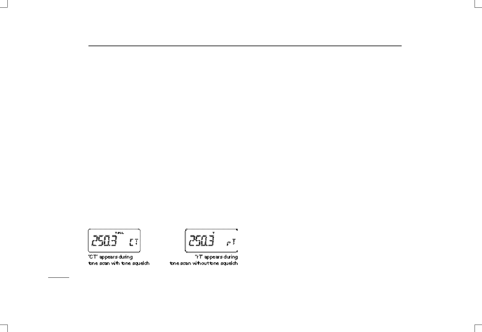
•“CT” appears during tone scan when the tone squelch is acti-
vated; “rT” appears when the tone squelch is not activated.
•Subaudible tone frequencies flash as they are scanned.
➃Push [TSCAN)] (or [PTT] or [VFO]) to stop the scan.
■Pocket beep operation
This function uses subaudible tones for calling and can be
used as a “common pager” to inform you that someone has
called you while you were away from the transceiver.
DWaiting for a call from a specific station
➀Set the operating frequency.
➁Set the desired subaudible tone (same as that used for
tone squelch operation, “CT”) in set mode.
•See previous page for programming.
➂Push [MULTI] to enter subaudible tone mode.
•“T” appears; if “D” appears, push [MULTI(↕)] to select “T.”
➃Push [MULT I (↔)] (or rotate [DIAL]) one or more times until
“TSQLS” appears; then push [VFO] to exit set mode.
➄When a signal with a matched tone is received, the trans-
ceiver emits beep tones for 30 sec. and flashes “S.”
➅Push [PTT] to answer or push [VFO] to stop the beeps and
flashing.
•Tone squelch is automatically selected.
DCalling a waiting station using pocket beep
Asubaudible tone matched with the station’s tone frequency
is necessary. Use the tone squelch on the previous page or
subaudible tone encoder (p. 15).
IC-T81A/E Manual 98.12.16 4:40 PM Page 26 (1,1)
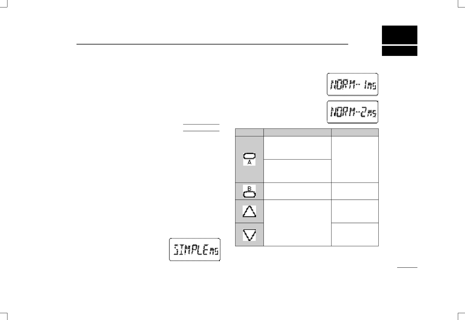
☞NOTE: VFO mode cannot be se-
lected via the microphone when
SIMPLE mode is selected.
NORMAL 1/NORMAL 2
NORMAL1:
BAND
Selects a band.
No function in memory mode.
NORMAL2:
MONITOR
Toggles squelch between
open and closed.
VFO/MEMORY
Toggles VFO and memory
mode.
Change the frequency or
memory channel when
pushed.
Start previously selected scan
when pushed and held.
•Normal 2 (while squelch is
open):
Adjust volume.
27
10OTHER FUNCTIONS
■Help function
When in set mode or initial set mode and no operation is per-
formed for 5 sec., the name of the selected item scrolls
across the function display for convenience.
■Initial set mode
Initial set mode is accessed at power on and allows you to
set seldom-changed settings. In this way you can “customize”
transceiver operations to suit your preferences.
➀While pushing [MULTI], push [PWR] to turn power on.
•The transceiver enters initial set mode and an initial set mode
item is displayed.
➁Push [MULTI(↕)] to select the desired display as described
on the following pages.
➂Push [MULT I (↔)](or rotate [DIAL]) to select the desired
condition.
➃Push [VFO] (or [PTT]) to exit initial set mode for regular op-
eration.
DOptional HM-75A functions
Microphone simple mode is used to
change the function assignments for
switches on the optional HM-75A
R E
-
M O T E C O N T R O LM I C R O P H O N E
as at right.
AT
POWER ON SWITCH SIMPLE
MONITOR
Toggles squelch be-
tween open and
closed.
CALL
Selects the call
M00
Selects memory
M01
Selects memory
☞N O T E : During transmit, pushing [A] transmits a 1750 Hz
tone for Europe, France and Italy versions.
IC-T81A/E Manual 98.12.16 4:40 PM Page 27 (1,1)
28
10 OTHER FUNCTIONS
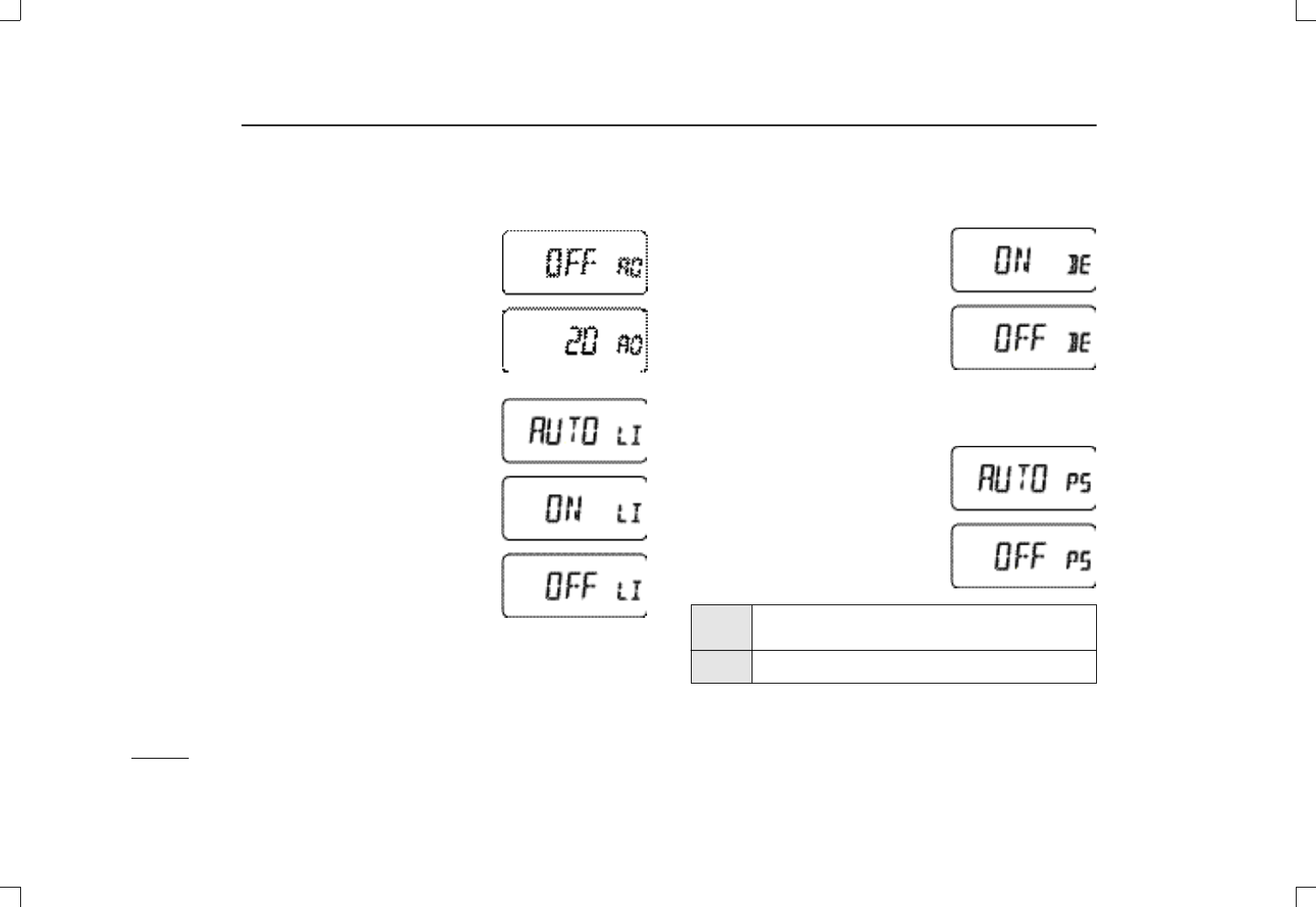
DAuto power OFF
This item allows you to set a time at
which the transceiver will automati-
cally turn off. The power off time can
be set to 20, 40, 60 min. or turned
OFF (default).
DDisplay backlighting
When set to A U TO (default), display
backlighting automatically turns on
when a key is pushed; when set to
O F F, display backlighting cannot be
turned ON; when set to ON, display
backlighting remains ON continu-
ously.
DBeep tones ON/OFF
Confirmation beep tones normally
sound when you push a key or switch.
These can be turned ON (default) or
OFF as you prefer.
DAuto repeater (see p. 17)
DPower saver
This item sets the power saver duty
cycle—the ratio of receive circuit on to
receive circuit off while standing by.
The duty cycle can be set to auto-
matic (default) or OFF. Setting to au-
tomatic conserves battery power.
AUTO Selects “1:4” duty ratio when receiving no signal
for 5 sec., then “1:8” 60 sec. after that.
OFF No power saver function.
IC-T81A/E Manual 98.12.16 4:40 PM Page 28 (1,1)
29
10OTHER FUNCTIONS
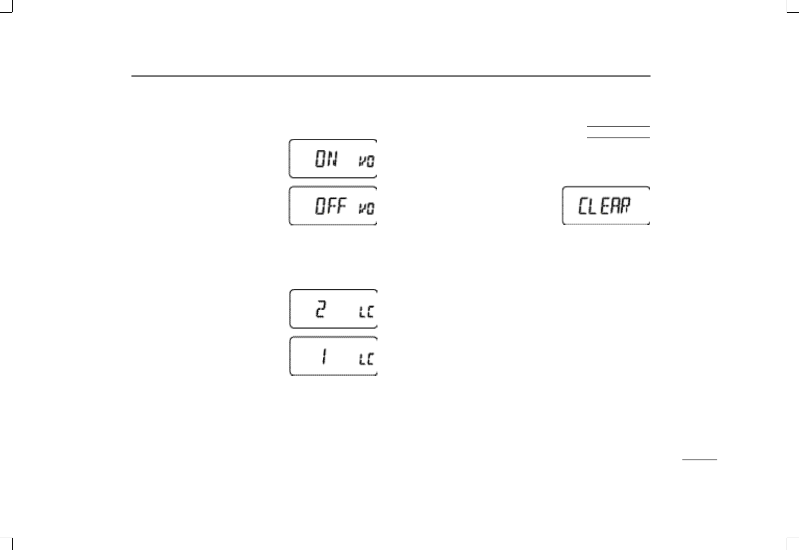
DVoltage display
This item sets the voltage display ON
(default) or OFF. When set to ON,
battery voltage is briefly displayed
after turning power on.
DDTMF speed (see p. 21)
DFunction display contrast
This item sets the function display
contrast to one of two levels—“1” is
low contrast and “2” (default) is high
contrast.
■Resetting the CPU
Reset the CPU before operating the transceiver for the fir s t
time, or when the internal CPU malfunctions.
➥While pushing [SQL] + [ V F O ] +
[MR], push [PWR] to turn power on
and reset the transceiver’s CPU.
•“CLEAR” appears briefly to indicate
the CPU has been reset.
uCAUTION: Resetting the CPU returns all programmed
contents to their default settings.
AT
POWER ON
IC-T81A/E Manual 98.12.16 4:40 PM Page 29 (1,1)
30
10 OTHER FUNCTIONS
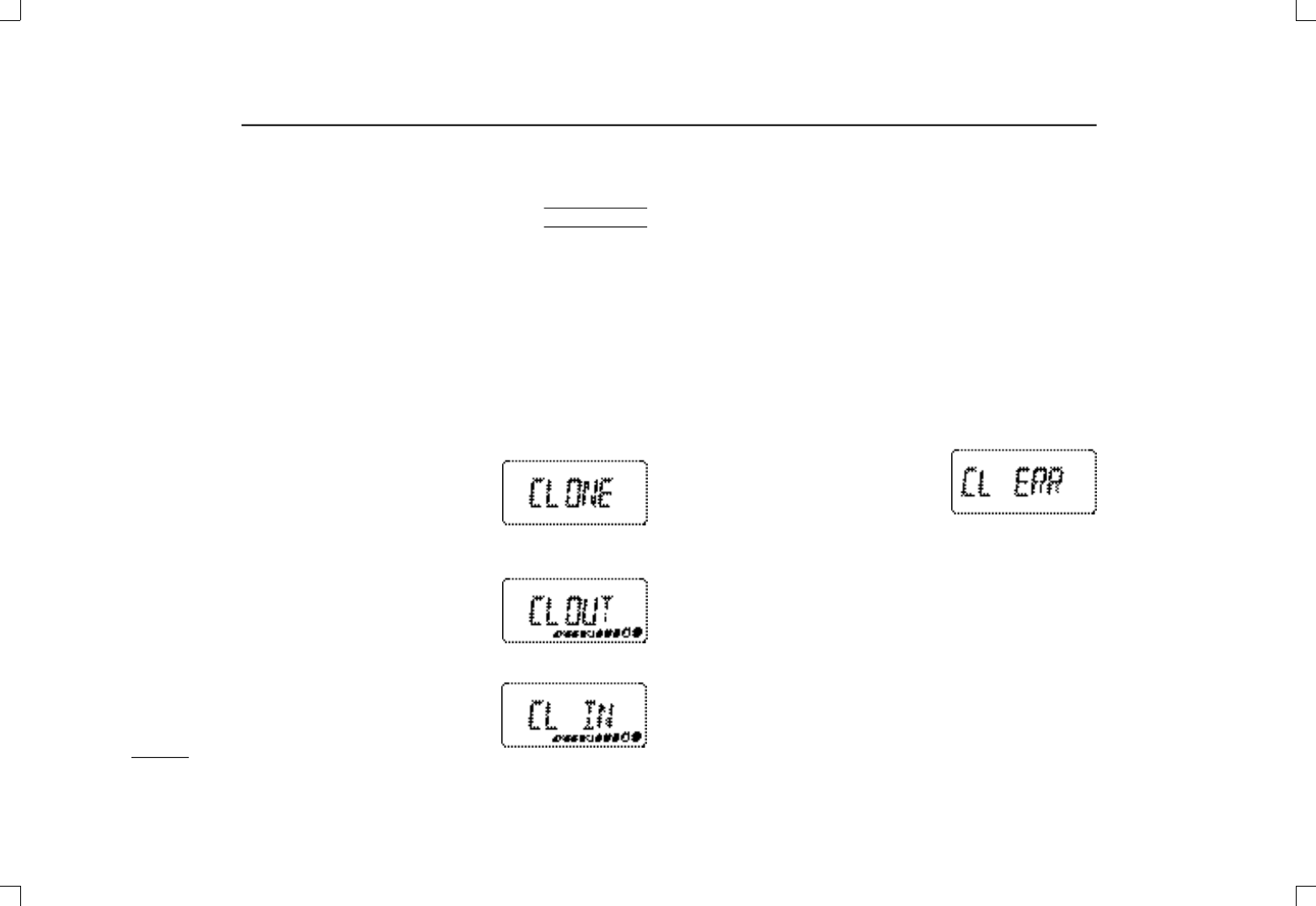
■Cloning
Cloning allows you to quickly and easily transfer the pro-
grammed contents from one transceiver to another trans-
ceiver; or, data from a PC to a transceiver using the optional
CS-T81
CLONING SOFTWARE
.
DTransceiver-to-transceiver cloning
➀Connect the OPC-474
C L O N I N G C A B L E
with adapter plugs
to the [SP] jack of the master and slave transceivers.
•The master transceiver is used to send data to the slave trans-
ceiver.
➁While pushing [MR], push [PWR]
to enter cloning mode (master
transceiver only—power on only for
slave transceiver).
•“CLONE” appears and the transceivers enter the clone standby
condition.
➂Push [PTT] on the master trans-
ceiver.
•“CLOUT” appears in the master trans-
c e i v e r’s display and the S/RF indica-
tor shows that data is being transferred to the slave transceiver.
•“ C L IN” appears automatically in the
slave transceiver’s display and the
S/RF indicator shows that data is
being received from the master trans-
AT
POWER ON ceiver.
• When cloning is finished, “CLONE” appears in the master trans-
c e i v e r’s display and “CLEND” appears in the slave transceiver’s
display.
➃When cloning is finished, turn power off, then on again to
return to normal operation.
DCloning using a PC
Data can be cloned to and from a PC (IBM compatible) using
the optional CS-T81
C L O N I N G S O F T WA R E
and the optional
OPC-478
CLONING CABLE
.
DCloning error
☞N O T E :DO NOT push the [PTT] on
the slave transceiver during
cloning. This will cause a cloning
error.
When the display at right appears, a cloning error has oc-
curred.
In such a case, memory contents return to their default set-
tings and both transceivers automatically enter VFO m o d e .
Cloning must then be repeated.
IC-T81A/E Manual 98.12.16 4:40 PM Page 30 (1,1)

11TROUBLESHOOTING
31
If your transceiver seems to be malfunctioning, please check
the following points before sending it to a service center.
PROBLEM
No power comes on.
Transmitting is impossible.
Frequency cannot be set.
Scan does not function.
[Y] or [Z] keys do not
function when using the
optional HM-75A.
Squelch does not open for
received signals.
Some memory channels
cannot be selected.
RIT/VXO offset cannot be
adjusted.
Cannot transmit on the 50
MHz band.
POSSIBLE CAUSE
•The battery is exhausted.
( A slight current flows in the circuits even when the
power is off.)
•The battery is exhausted.
•Memory (call) mode is selected.
•The lock function is activated.
•The same frequencies are programmed into XA
and XB (a pair of scan edges).
• Only CH00 is programmed; or, all other memory
channels are set as skip channels.
•Memory channels 00 and/or 01 are not pro-
grammed and simple mode is selected.
•Tone squelch is activated.
•Some memories have been cleared.
•RIT/VXOfunction has not been activated or the
1200 MHz band is not selected.
•AM mode has been set for the 50 MHz band.
SOLUTION
•Charge the battery pack or place new dry cell bat-
teries in the battery case.
(Remove the battery pack if you will not be using the trans-
ceiver for a long time.)
•Charge the batteries or place new dry cells in the
battery case.
•Push [VFO] to select VFO mode.
•Push [(H/L) LOCK)] for 1 sec.
•Program different frequencies.
•Program additional memories; or, cancel skip set-
tings for one or more channels.
•Program the memory channels or set to microphone
normal 1 or normal 2.
•Turn off the tone squelch.
•Program the cleared memories.
•Activate the RIT/VXOfunction in set mode or push
[MULTI(↔)] to select the 1200 MHz band.
•Turn AM mode off in set mode.
REF.
pgs. 7,
8
pgs. 7,
8
p. 9
p. 11
p. 18
pgs.
18, 24
pgs.
18, 27
p. 25
p. 19
p. 13
p. 14
IC-T81A/E Manual 98.12.16 4:40 PM Page 31 (1,1)

SPECIFICATIONS
12
32
GENERAL
•Frequency coverage : (Unit: MHz)
Version 50 MHz 144 MHz 430 MHz 1.2 GHz WFM*4
USA 50–54 Rx: 118–174*1 Rx: 400–470*2
1240–1300 76–107.995
50–52 Tx: 144–148 Tx: 430–450*2
Europe 50–52 144–146 430–440 1240–1300 88–107.995
UK (Rx only*)
Italy 50–52 136–174*1 400–470*3 1240–1300 88–107.995
Asia 50–54 Rx: 118–174*1
430–440 1240–1300 76–107.995
Tx: 136–174*1
Australia 50–54 144–148 430–440 1240–1300 88–107.995
Taiwan N/A 144–146 430–440 1260–1265 76–107.995
*Some versions may be able to transmit.
•Operating mode :FM(F3E), WFM(Rx), AM(Rx)
•No. of memory channels :124 (100 regular, 20 program scan
edges and 4 call)
•Tuning steps :5*, 10, 12.5, 15*, 20, 25, 30, 50 and
100 kHz
*Not available for 1200 MHz band.
•Frequency stability :±3 ppm (–10°C to 60°C; 14°F to 140°F)
•Power supply requirements (negative ground):
4.5 to 16 V DC or specified battery
pack/case
•Current drain( at 13.5 V DC):
Rx Power saved 40 mA(typ.)
standby 80 mA(typ.; 90 mA: 1200 MHz)
rated audio 220 mA(typ.)
Tx max. power 1.4 A(0.8 Atyp.: 1200 MHz)
•Antenna connector :SMA(50 Ω)
•Usable temperature range :–10°C to +60°C; +14°F to +140°F
•Dimensions :58(W)×106(H)×28.5(D) mm;
29⁄32(W)×43⁄16(H)×11⁄8(D) in
•Weight (approx.) :300 g; 10.6 oz (w/ant. & BP-197)
280 g; 9.9 oz (w/ant. & BP-199)
310 g; 10.9 oz (w/ant. & BP-200)
TRANSMITTER
•Modulation system :Variable reactance modulation
•Output power(at 13.5 V DC) :High 5 W typ.
(except 1200 MHz)
1 W
(1200 MHz)
Low 0.5 W typ.
(0.1 W typ. for 1200
MHz)
•Spurious emissions :Less than –60 dB
(Less than –40 dB for 1200 MHz)
•Max. frequency deviation :±5 kHz
•Ext. microphone connector :
3-conductor 2.5(d) mm (
1
⁄
8
″)/ 2 kΩ
RECEIVER
•Receive system :Double conversion
superheterodyne
•Intermediate frequencies :1st 69.45 MHz (FM)
13.35 MHz (WFM)
2nd 450 kHz
•Sensitivity (except spurious points) :
FM 50 MHz Less than 0.18 µV
(at 12 dB SINAD) 144 MHz Less than 0.18 µV
430(440) MHz Less than 0.18 µV
1200 MHz Less than 0.25 µV
WFM 91.5 MHz Less than 1.99 µV
(at 12 dB SINAD; 1 kHz/52.5 kHz deviation)
•Squelch sensitivity :0.18 µV (FM)
0.25 µV (1200 MHz)
5.6 µV (WFM)
•Spurious and image rejection ration:
50, 144 MHz bands Less than –60 dB
430(440) MHz band Less than –50 dB
1200 MHz band Less than –50 dB
(–50 dB typ. for half IF; except 2nd image, 50 MHz band IF and WFM)
•Audio output power (at 25°C) :250 mW typ.at 10% distortion with an
8 Ω load
IC-T81A/E Manual 98.12.16 4:40 PM Page 32 (1,1)
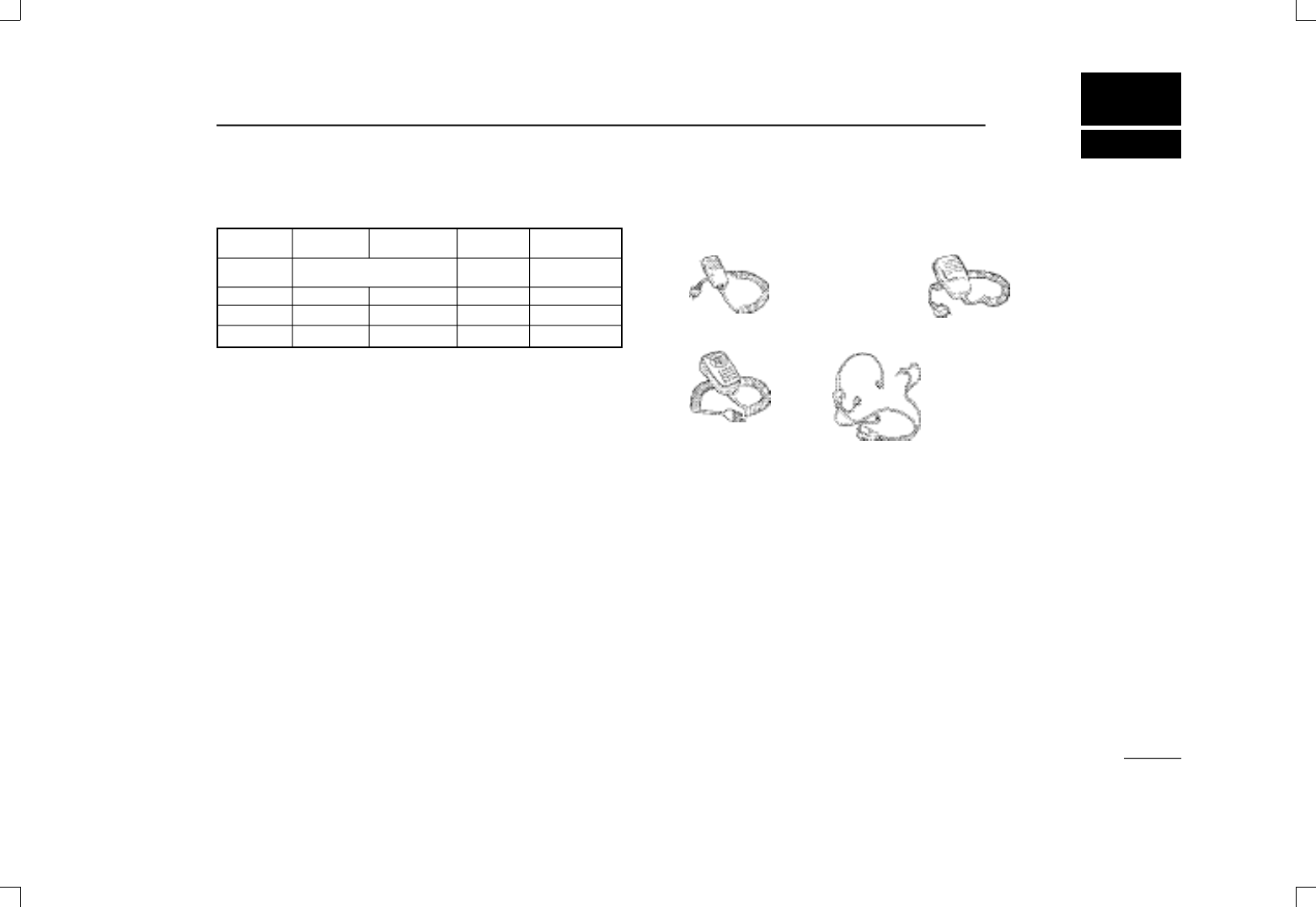
13OPTIONS
33
DBattery packs
BATTERY VOLTAGE CAPACITY OUTPUT OPERATING
PACK POWER PERIOD*
BP-197 Battery case for R6(AA) 0.8 W 10/14 hr
×3 alkaline or Ni-Cd cells
BP-198 4.8 V 700 mAh 1.2 W 6/8.5 hr
BP-199 6.0 V 700 mAh 2.0 W 4/8 hr
BP-200 9.6 V 680 mAh 4.5 W 4/7 hr
*Operating periods are calculated under the following conditions:
Tx:Rx:standby=1:1 :8;
Longer operating times are when operating on the 1200 MHz band.
DChargers and cables
BC-110A/C/D/V WALLCHARGER
Regularly charge battery packs attached to the transceiver in 15 hrs.
BC-119 DESKTOP CHARGER+
AD-88 TERMINALPC BOARD FOR CHARGER +
AD-87 BATTERY PACK ADAPTER +
Rapidly charge battery packs in 1 to 1.5 hrs. depending on the battery
pack. An AC adapter is packed with the BC-119 (except for the UK
version). The AD-87 must be used with the BC-119 for charging the
battery pack. The CP-17L or OPC-515L can be used instead of the
supplied AC adapter.
CP-12L CIGARETTE LIGHTER CABLE WITH NOISE FILTER
For operation and charging via a 12 V cigarette lighter socket.
OPC-254L DC POWER CABLE
For operation and charging via an external power supply.
DSpeaker-microphones
DOthers
CS-T81 CLONING SOFTWARE
Allows you to clone the memory contents of an IC-T81 transceiver
between transceivers or to a PC for editing.
LC-148 CARRYING CASE
SP-13 EARPHONE
Provides clear receive audio in noisy environments.
HM-46 HM-54
HM-75A HS-85
•PTTswitch
•VOX
•One-touch PTTfor
hands-free operation
Remote control
capability (see p. 27)
IC-T81A/E Manual 98.12.16 4:40 PM Page 33 (1,1)
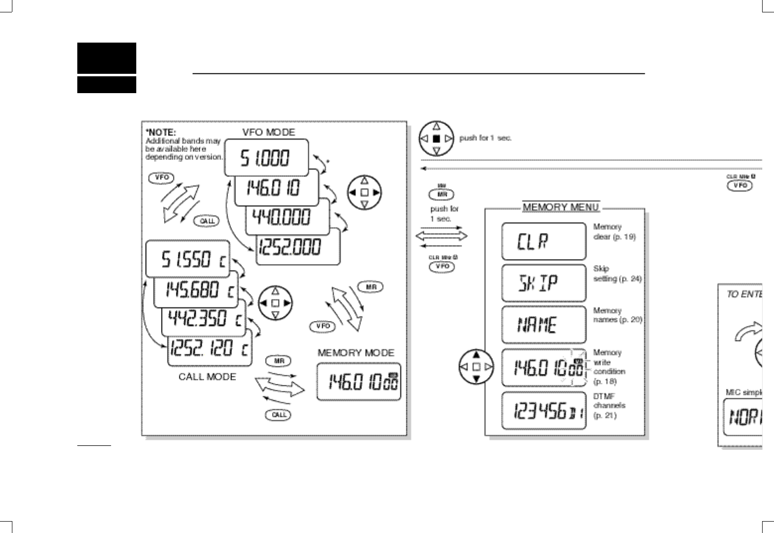
MODE ARRANGEMENT
14
34
IC-T81A/E Manual 98.12.16 4:40 PM Page 34 (1,1)
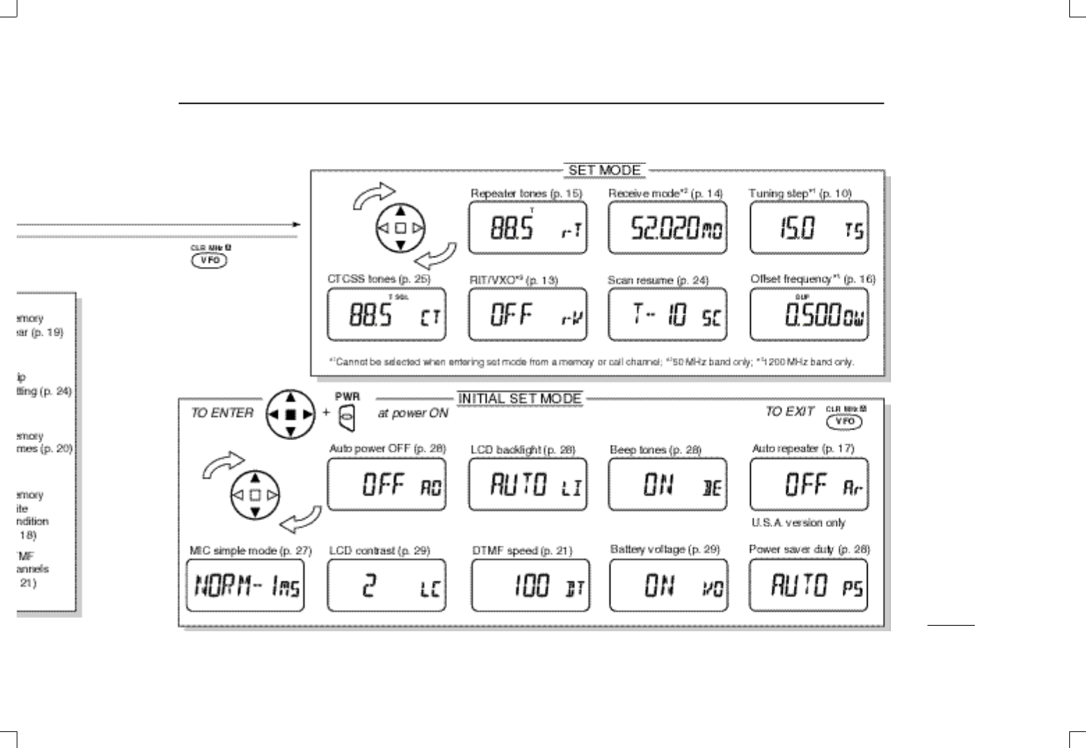
14MODE ARRANGEMENT
35
IC-T81A/E Manual 98.12.16 4:40 PM Page 35 (1,1)

Count on us!
6-9-16 Kamihigashi, Hirano-ku, Osaka 547-0002 Japan
A-5518D-1EX
Printed in Japan
© 1998 Icom Inc.
IC-T81A/E Manual 98.12.16 4:40 PM Page 36 (1,1)