ICOM orporated IC-T90A Amateur Transceiver with Scanning Receiver User Manual IC T90A IM
ICOM Incorporated Amateur Transceiver with Scanning Receiver IC T90A IM
UserManual.wiki
>
ICOM orporated
>
IC T90A User Manual
Users Manual
Navigation menu
Upload a User Manual
Namespaces
Wiki Guide
HTML
PDF
Info
Views
User Manual
Discussion / Help
Navigation
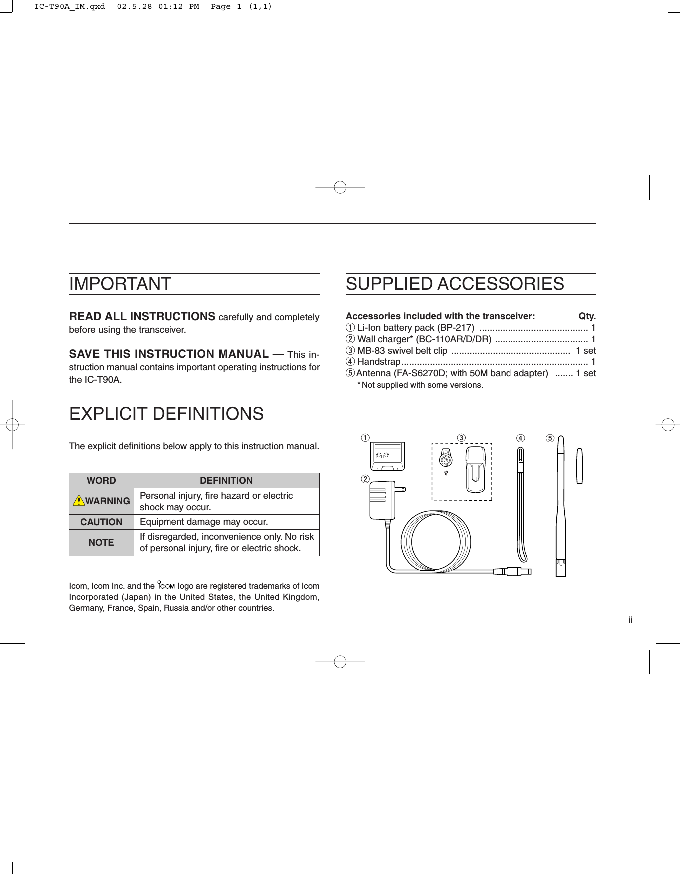
![ivFOREWORD ............................................. iIMPORTANT ............................................. iiEXPLICIT DEFINITIONS .......................... iiSUPPLIED ACCESSORIES ..................... iiCAUTIONS ............................................... iiiTABLE OF CONTENTS ........................... ivqQUICK REFERENCE GUIDE ........ 1 – 6wPANEL DESCRIPTION ................ 7– 12■Panel description ............................. 7■Function display ............................. 11eBATTERY CHARGING .............. 13 – 16■Battery attachment ......................... 13■Battery cautions ............................. 13■Regular charging ........................... 14■Rapid charging ............................... 15■Battery case ................................... 16■External power operation ............... 16rBASIC OPERATION .................. 17 – 34■Turning power ON ......................... 17■Tuning step .................................... 18■Setting a frequency ........................ 19■Mode selection ............................... 20■Operating band and receive modeselection ......................................... 21■Setting squelch level ...................... 22■Receiving ....................................... 23■RIT function ................................... 27■Attenuator function ......................... 27■Transmitting ................................... 28■Repeater operation ........................ 29■Duplex operation ............................ 31■Split operation ................................ 32■Auto repeater function ................... 33■1750 Hz tone ................................. 34tMEMORY/CALL CHANNELS .... 35 – 44■General .......................................... 35■Calling up memory channels ......... 36■Programming memory channels .... 37■Transferring memory contents to VFO ........................................... 38■Copying memory contents ............. 39■Memory names .............................. 39■Memory bank ................................. 41■Memory clear ................................. 43■Call channel ................................... 44ySCAN OPERATION ................... 45 – 49■Scan types ..................................... 45■VFO scan ....................................... 46■Frequency skip function ................. 47■Skip channel setting ....................... 47■Memory scan ................................. 48■Memory bank scan ........................ 48■Scan notes ..................................... 49uPRIORITY WATCH .................... 50 – 54■Priority watch types ........................ 50■Priority alert .................................... 50■Priority watch operation ................. 51iSET MODE ................................ 55 – 66■Set mode ....................................... 55■Set mode items ............................. 56oOTHER FUNCTIONS ................ 67– 80■Programming a DTMF code .......... 67■Transmitting a DTMF code ............ 68■Clearing a DTMF memory ............. 69■Confirming a DTMF memory ......... 69■Tone frequency and DTCS code .... 70■Tone/DTCS squelch ....................... 71■Pocket beep ................................... 71■Available tone frequencies ............. 72■Available DTCS code ..................... 72■Tone scan ...................................... 73■Beep tones ..................................... 74■Dial speed acceleration ................. 74■Lock function .................................. 74■Morse code synthesizer ................. 75■Power save .................................... 75■Time-out timer ................................ 76■PTT lock ......................................... 76■Auto power OFF ............................ 76■Auto power ON .............................. 76■Weather channel operation ............ 77■Cloning function ............................. 79■[SP/MIC] jacks ............................... 79■Resetting ........................................ 80!0 HM-75A REMOTE CONTROLMICROPHONE ................................. 81!1 TROUBLESHOOTING ..................... 82!2 TV FREQUENCY TABLE ........... 83 – 86!3 SPECIFICATIONS ..................... 87 –88!4 OPTIONS ................................... 89– 90POCKET GUIDETABLE OF CONTENTSqqwweerrttyyuuiioo!!00!!11!!22!!33!!44IC-T90A_IM.qxd 02.5.28 01:12 PM Page 3 (1,1)](https://usermanual.wiki/ICOM-orporated/IC-T90A/User-Guide-257988-Page-5.png)
![41QUICK REFERENCE GUIDE■Charging the Li-Ion battery packDCharging with the wall chargerqPush and hold [PWR] to turn the transceiver power OFF.wInsert the charger plug into the DC power jack of the trans-ceiver.ePlug the charger into AC wall outlet.rCharging starts and battery indicator “” on the displayblinks. tIt takes approximately 15 hours to charge an empty BP-217 Li-Ion battery pack.yUnplug the charger from the AC wall outlet when chargingis completed.DCharging with the CP-19 Cigarette Lightercable (optional)qInsert the cigarette lighter adapter cable into the DC powerjack of the transceiver.wConnect the CP-19 cigarette lighter adapter cable to thecigarette lighter socket.eCharging starts and battery indicator on the display flash.NOTE:•The BP-217 can be charged in background during you operate thetransceiver. (p. 5).•Charging will be suspended during transmitting.•“CHG_F” appears when the charging is completed with the powerturned OFF.•NEVER connect the cigarette lighter socket or external regulatedDC power supply directly to the transceiver. Such a connection willdamage the transceiver.•Remove CP-19 from the transceiver when not using it. Otherwise,the vehicle battery will become exhausted.IC-T90A with BP-217BC-110AR/D/DRtoDC power jackto AC outletCP-19 (optional)toDC powerjackto a 12 V cigarette lightersocketQUICK REFERENCE GUIDEqqIC-T90A_IM.qxd 02.5.28 01:12 PM Page 7 (1,1)](https://usermanual.wiki/ICOM-orporated/IC-T90A/User-Guide-257988-Page-9.png)
![51QUICK REFERENCE GUIDE■Rapid chargingThe optional BC-139 provides rapid charging of the batterypack.CAUTION: To avoid damage to the transceiver, turn trans-ceiver OFF while charging.•Charging period: 2.5 hours (w/BP-217)■External power operationAn optional CP-19 cigarette lighter cable can be used for ex-ternal power operation from a 12 V DC cigarette lightersocket.•Power supply range is between 5.5–11.5 V DC. NEVER CONNECT OVER 11.5 V DC direct into theDC power jack of the transceiver.•BE SURE to use the CP-19 when connecting a regulated 12 V DC power supply.•If a battery pack is attached, the voltage of the externalpower supply must be within 11.5–16 V DC, otherwise,the battery power may be used for operation. •The maximum output power is 5.0 W regardless of thepower supply voltage.•Remove the cables from the transceiver when not usingit. Otherwise, the vehicle battery will become exhausted.CP-19 (optional)toDC powerjackto a 12 V cigarette lightersocketTurn powerOFF.Check the orientation.BP-217Li-Ion battery packto AC outletBC-139 (optional)desktop chargerBC-123(supplied with BC-139)to [AC ADAPTER] jackAAdapter (suppliedwith BC-139)LEDCharging: OrangeFinished: GreenCharging terminalIC-T90A_IM.qxd 02.5.28 01:12 PM Page 8 (1,1)](https://usermanual.wiki/ICOM-orporated/IC-T90A/User-Guide-257988-Page-10.png)
![61QUICK REFERENCE GUIDE■Your first contactNow that you have your IC-T90A ready to operation, you areprobably excited to get on the air. We would like to take youthrough a few basic operation steps to make your first “OnThe Air” an enjoyable experience. DFirst contactqPush and hold [PWR] for 1 sec. to turn the transceiverpower ON.•The function display shows “ICOM,” current voltage then the op-erating frequency.wPush [BAND] several times until desired operating band(VHF; 51.000, 146.010 or UHF; 440.000 as default)appears on the display.ePush [Y](or [Z]) several times to adjust desired audiolevel.rRotate [DIAL] to select receive frequency.‘Direct frequency input’via the keypad also available. (p. 19)tHold the transceiver approximately 2 in. (5 cm) from yourmouth.yPush and hold [PTT], then speak in your normal voicelevel.uRelease [PTT] switch to receive.•Repeat steps, t, yand uto continue communication.reqwyu[DIAL][PTT][UP/DOWN][BAND][PWR][Mic]QUICK REFERENCE GUIDEFM DUP SKIPTP[EXAMPLE] Setting thereceive frequency to444.350 MHzqqIC-T90A_IM.qxd 02.5.28 01:12 PM Page 9 (1,1)](https://usermanual.wiki/ICOM-orporated/IC-T90A/User-Guide-257988-Page-11.png)
![■Panel description qPOWER SWITCH [PWR]Push for 1 sec. to turn the transceiver power ON and OFF.wBAND SWITCH [BAND]➥Push to select the operating band (5MHz, Air, VHF, UHF,etc.). (p. 21)➥Push to select the memory bank or push to proceed thememory name cursor while programming the memoryoption. (pgs. 39, 41)➥Push for 1 sec. to have Morse code synthesizer. (p. 75)➥While pushing [PTT], this key sends a DTMF “D.”eUP/DOWN SWITCHES [Y]/[Z]➥Push to adjust the audio level by default. (p. 17)➥Push to adjust the frequency when [Y]/[Z] and [DIAL]are exchanged by pushing [1 V↔D] for 1 sec. (p. 23)rMONITOR SWITCH [SQL] (p. 22)➥Push and hold to temporarily open the squelch andmonitor the operating frequency.➥While pushing, rotate the tuning dial to set the squelchthreshold level.tTRANSMIT/RECEIVE INDICATOR➥Lights green while receiving a signal or when thesquelch is open; lights red while transmitting.➥Flashes green for 5 sec. when the scan stop LED func-tion is in use and a scan is stopped. (pgs. 46, 62)tuio!0!1!2!3!4Keypad !6–@5!5erqwyFunction displaySpeakerMicrophone72PANEL DESCRIPTIONIC-T90A_IM.qxd 02.5.28 01:12 PM Page 10 (1,1)](https://usermanual.wiki/ICOM-orporated/IC-T90A/User-Guide-257988-Page-12.png)
![82PANEL DESCRIPTIONyPTT SWITCH [PTT]➥Push and hold to transmit in 50/144/430 MHz amateurbands; release to receive. (p. 28)•When WFM or AM mode is selected, transmission is impossi-ble.uANTENNA CONNECTOR (p. 3)Connects the supplied antenna.iEXTERNAL SPEAKER AND MICROPHONE JACKS[SP/MIC]Connects an optional speaker-microphone or headset, ifdesired. The internal microphone and speaker will notfunction when any external equipment is connected. (Seepgs. 89, 90 for a list of available options.)oTUNING DIAL [DIAL]➥Rotate [DIAL] to set operating frequencies, memorychannels, set mode contents, etc. (pgs. 19, 36, 55)➥While pushing [SQL], sets the squelch level. (p. 22)➥While pushing [BAND], sets the operating band in VFOmode. (p. 21)➥While pushing [Y]/[Z], adjusts the audio level (when[Y]/[Z] and [DIAL] are not exchanged). (p. 17)!0 EXTERNAL DC POWER JACK [DC 11.0 V]➥Allows charging of the BP-217 using the BC-110A/D wallcharger, or using an optional CP-19 cigarette lightercable.➥To connect regulated power supply with optional CP-19cigarette lighter cable.!1 MODE/SCAN SWITCH [MODE SCAN]➥Push to select the operating mode (FM, WFM,AM). (p. 21)➥Push for 1 sec. to start a scan. (p. 45)➥While pushing [PTT], this key sends a DTMF “#” (F).!2 VFO SWITCH [VFO MHz]➥Selects and toggles between VFO A and B. (p. 20)➥Selects and toggles between the 1 MHz or 10MHz tuning steps when pushed for 1 sec. (p. 18)➥Returns to previous operating condition while setting fre-quency or memory channel, or while in set mode.➥While pushing [PTT], this key sends a DTMF code “A”.!3 MEMORY SWITCH [MR S.MW] ➥Selects and toggles between memory modeand memory bank. (p. 20)➥Push for 1 sec. to enter memory write condi-tion. (p. 37)➥Push for 2 sec. to write the operating frequency into theselected memory channel in VFO mode.•Keep pushing for 2 sec. or more to automatically select thenext memory channel, if desired. (p. 38)➥Push [MR S.MW] for 2 sec. to transfer the displayed fre-quency into the VFO in memory mode. (p. 38)MRS.MWBVFOMHzAMODESCANwwPANEL DESCRIPTIONIC-T90A_IM.qxd 02.5.28 01:12 PM Page 11 (1,1)](https://usermanual.wiki/ICOM-orporated/IC-T90A/User-Guide-257988-Page-13.png)
![92PANEL DESCRIPTION➥While pushing [PTT], this key sends a DTMF “B”.!4 CALL/LOCK SWITCH [CALL/TV LOCK]➥Toggles between call channel, TV channel,weather channel (U.S.A. version only) andVFO mode in sequence. (p. 20)➥Push for 1 sec. to toggle the lock function ON and OFF.(p. 74)•“é” appears while the key lock function is in use.➥While pushing [PTT], this key sends a DTMF code “C”.!5 DTMF MEMORY SWITCH [• DTMF.M]➥Push for 1 sec. to enter the DTMF memorychannel. (p. 67)➥Inputs MHz digit for frequency input. (p. 19)➥While pushing [PTT], this key sends a DTMF cod “M(E)”.!6 VOLUME/DIAL SWITCH [1 V↔D]➥Push for 1 sec. to exchange [Y]/[Z] and[DIAL] functions. (p. 23)•“VOL” appears when the tuning dial functions as avolume control.➥Inputs digit ‘1’for frequency input, memory channel se-lection, etc.➥While pushing [PTT], this key sends a DTMF code “1”.!7 TONE SWITCH [2 TONE] (p. 70)➥Push for 1 sec. to activate the following tonefunctions in order.•Subaudible tone encoder — “T” appears. (p. 29)•Tone squelch — “T SQL” appears. (p. 71)•Pocket beep — “T SQLS” appears. (p. 71)•DTCS squelch — “DTCS” appears. (p. 71)•DTCS beep — “SDTCS” appears. (p. 71)•No tone operation — no tone indicator appears.➥Inputs digit ‘2’for frequency input, memory channel se-lection, etc.➥While pushing [PTT], this key sends a DTMF code “2”.!8 OUTPUT POWER SWITCH [3 H/L] (p. 28)➥Push for 1 sec. to toggle output power be-tween high and low.•“LOW” appears when low output power is selected.➥Inputs digit ‘3’for frequency input, memory channel se-lection, etc.➥While pushing [PTT], this key sends a DTMF code “3”.!9 DUPLEX SWITCH [4 DUP] (pgs. 29, 31)➥Push for 1 sec. to activate the following duplexfunctions in order.•Minus duplex operation — “–DUP” appears.•Plus duplex operation — “DUP” appears.•Simplex operation — no duplex indicator appears.➥Inputs digit ‘4’for frequency input, memory channel se-lection, etc.➥While pushing [PTT], this key sends a DTMF code “4”.4DUP3H/L2TONE1V D.DTMF.MCALL/TVLOCKCIC-T90A_IM.qxd 02.5.28 01:12 PM Page 12 (1,1)](https://usermanual.wiki/ICOM-orporated/IC-T90A/User-Guide-257988-Page-14.png)
![102PANEL DESCRIPTION@0 FREQUENCY SKIP SWITCH [5 SKIP]➥Push for 1 sec. to turn the frequency skip func-tion ON and OFF in VFO mode. (p. 47)•“P SKIP” appears when the frequency skip functionis in use.➥Push for 1 sec. to set the memory channel as the fol-lowing skip channel in memory mode in order. (p. 48)•Skip channel — “SKIP” appears. •Frequency skip channel — “P SKIP” appears. •Non-skip channel — no skip indicator appears.➥Push for 1 sec. to program the pausing frequency as askip frequency while scanning. (p. 48)➥Inputs digit ‘5’for frequency input, memory channel se-lection, etc.➥While pushing [PTT], this key sends a DTMF code “5”.@1 MEMORY NAME SWITCH [6 M.N]➥Push for 1 sec. to turn the memory name indi-cation ON and OFF. (p. 39)•Frequency appears for nameless memory chan-nels.➥Inputs digit ‘6’for frequency input, memory channel se-lection, etc.➥While pushing [PTT], this key sends a DTMF code “6”.@2 TONE SCAN SWITCH [7 T.SCAN]➥Push for 1 sec. to start a tone scan. (p. 73)➥Inputs digit ‘7’for frequency input, memorychannel selection, etc.➥While pushing [PTT], this key sends a DTMF code “7”.@3 SET MODE SWITCH [8 SET]➥Push for 1 sec. to enter the set mode. Push toselect the displayed set mode item after se-lecting with [DIAL] while in the set mode. (p. 55)➥Inputs digit ‘8’for frequency input, memory channel se-lection, etc.➥While pushing [PTT], this key sends a DTMF code “8”.@4 TUNING STEP SWITCH [9 TS]➥Push for 1 sec. to select the tuning step. (p. 18)➥Inputs digit ‘9’for frequency input, memorychannel selection, etc.➥While pushing [PTT], this key sends a DTMF code “9”.@5 RIT/ATTENUATOR SWITCH [0 RIT]➥Push for 1 sec. to enter the RIT/attenuator setmode. Push to select the item after selectingwith [DIAL]. (p. 27)•RIT function is available for 630.000 MHz and above.•Attenuator for 629.995 MHz or less.➥Inputs digit ‘0’for frequency input, memory channel se-lection, etc.➥While pushing [PTT], this key sends a DTMF code “0”.0RIT9TS8SET7T.SCAN6M.N5SKIPwwPANEL DESCRIPTIONIC-T90A_IM.qxd 02.5.28 01:13 PM Page 13 (1,1)](https://usermanual.wiki/ICOM-orporated/IC-T90A/User-Guide-257988-Page-15.png)
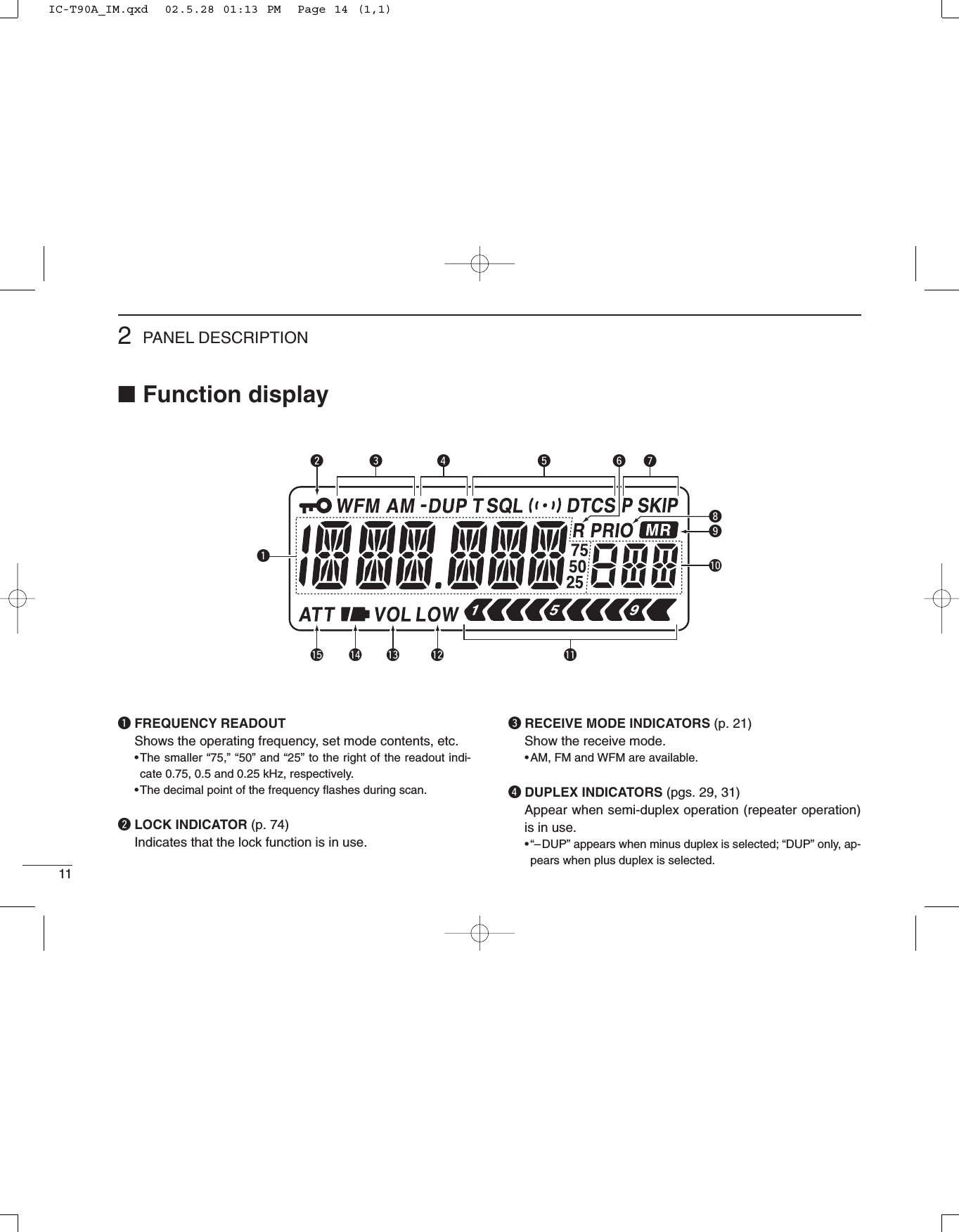
![122PANEL DESCRIPTIONtTONE INDICATORS (p. 70)➥Appear when the following tone functions are activated.•Subaudible tone encoder — “T” appears. (p. 29)•Tone squelch — “T SQL” appears. (p. 71)•Pocket beep — “T SQLS” appears. (p. 71)•DTCS squelch — “DTCS” appears. (p. 71)•DTCS beep — “SDTCS” appears. (p. 71)➥“S” flashes when the correct tone or code is receivedduring pocket/DTCS beep operation. (p. 71)yRIT INDICATOR (p. 27)Appears when the RIT (Receive Incremental Tuning) func-tion for 630.000 MHz and above is in use.uSKIP SCAN INDICATOR (p. 48)➥“SKIP” appears when a selected memory channel is setas a skip channel.➥“P SKIP” appears when the memory channel frequencyis set as a skip frequency in memory mode.➥“P SKIP” appears when the frequency skip function isturned ON in VFO mode.iPRIORITY WATCH INDICATOR (p. 50)Appears when priority watch is in use.oMEMORY MODE INDICATOR (p. 21)Appears when a memory channel is selected.!0 MEMORY CHANNEL NUMBER READOUT (p. 20)Shows the memory or call channel number, etc.!1 S/RF INDICATORS (p. 28)Shows the relative signal strength while receiving. Showsthe relative output power while transmitting.!2 LOW POWER INDICATOR (p. 28)Appears when low output power is selected.!3 VOLUME EXCHANGE INDICATOR (p. 23)Appears when the functions of tuning dial and [Y]/[Z]switches are exchanged.!4 BATTERY INDICATORS ➥Both segments appear when the batteries have amplecapacity. •They do not appear when operating with an external powersource.➥Only the right segment “” appears when the batteriesare nearing exhaustion.➥Flash while charging the attached Li-Ion battery pack.!5 ATTENUATOR INDICATOR (p. 27)Appears when attenuator is in use.wwPANEL DESCRIPTIONIC-T90A_IM.qxd 02.5.28 01:13 PM Page 15 (1,1)](https://usermanual.wiki/ICOM-orporated/IC-T90A/User-Guide-257988-Page-17.png)
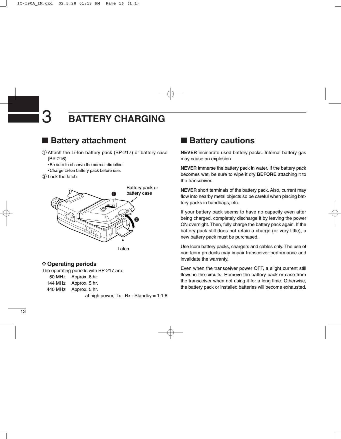
![143BATTERY CHARGING■Regular chargingPrior to using the transceiver for the first time, the batterypack must be fully charged for optimum life and operation.CAUTION: To avoid damage to the transceiver, turn trans-ceiver OFF while charging.•Recommended temperature range for charging:+32°F to +95°F; 0°C to +35°C•Use the wall charger* (BC-110AR/D/DR) only. NEVER useanother manufactures’charger.* Not supplied with some versions.•An optional cable CP-19 (for 12 V cigarette lighter socket)can be used instead of the AC adapters of the above charg-ers.DBattery indicatorsThe battery indicators flash while charging with no relation ofthe power condition.“CHG_F” appears when the charging is completed. Discon-nect the wall charger in this case.qAttach the battery pack to the transceiver.wBe sure to turn the transceiver power OFF.eConnect the AC adapter* (BC-110AR/D/DR) as shownbelow.* Not supplied with some versions.rRemove any cables from the [DC11V] jack.•Charging period: 15 hours (w/BP-217)eeBATTERY CHARGINGIC-T90A with BP-217 BC-110AR/D/DRto AC outletCP-19 (optional)toDC powerjackto a 12 V cigarette lightersocketIC-T90A_IM.qxd 02.5.28 01:13 PM Page 17 (1,1)](https://usermanual.wiki/ICOM-orporated/IC-T90A/User-Guide-257988-Page-19.png)
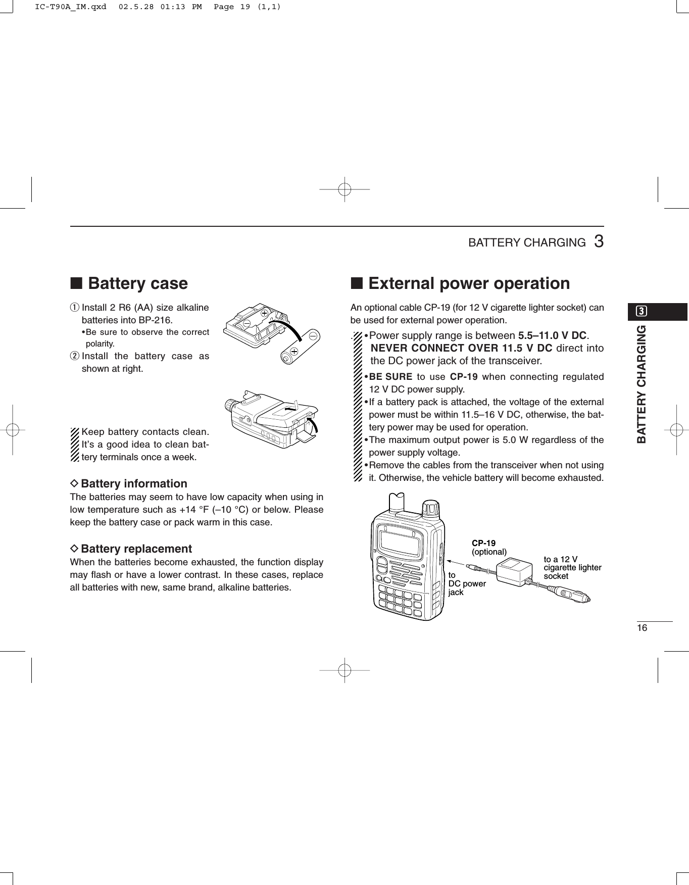
![153BATTERY CHARGING■Rapid chargingThe optional BC-139 provides rapid charging of the batterypack.•Charging period: 2.5 hours (w/BP-217)CAUTION: To avoid damage to the transceiver, turn it OFFwhile charging.•Recommended temperature range for charging:0°C to +35°C; +32°F to +95°F•NEVER connect 2 chargers to the [AC ADAPTER] and[DC11V] jacks.•Use the supplied BC-123 for the BC-139 desktop charger.Connect BC-123 to the [AC ADAPTER] jack.•NEVER use another manufactures’charger. •An optional cable CP-19 (for 12 V cigarette lighter socket)can be used instead of the supplied AC adapter. Connectone of these to the [DC11V] jack in this case.If the charge indicator flashes orange, there may be aproblem with the battery pack (or charger). Re-insert thebattery pack or contact your dealer.Turn powerOFF.Check the orientation.BP-217Li-Ion battery packto AC outletBC-139 (optional)desktop chargerBC-123(supplied with BC-139)to [AC ADAPTER] jackAAdapter (suppliedwith BC-139)LEDCharging: OrangeFinished: GreenCharging terminalIC-T90A_IM.qxd 02.5.28 01:13 PM Page 18 (1,1)](https://usermanual.wiki/ICOM-orporated/IC-T90A/User-Guide-257988-Page-20.png)
![174BASIC OPERATION■Turning power ONDTurning power ONqMake sure alkaline batteries are installed in the batterycase or battery pack is charged, and attach them. (p. 13)wPush [PWR] for 1 sec. to turn the power ON.•The function display shows “ICOM,” current voltage then the op-erating frequency.•Repeat this step to turn power OFF.The opening message can be turned ON or OFF in the ex-panded set mode 1. (p. 64)DSetting volume levelThe audio level can be adjusted through 32 levels.➥Push [Y] or [Z] to set the desired audio level.•Rotating the tuning dial while pushing [Y] or [Z] also sets theaudio level.•[Y]/[Z] and [DIAL] can be exchanged by [1 V↔D]. (p. 23)DVolume level indicationThe frequency display shows the volume level while settingas shown below.[∫][√]Shows volume level.[PWR]FM SKIPPFrequency indicationOpening message ‘ICOM’Voltage indicationIndication Audio level0 (no sound)19–23 (default)24–2728–3031 (Maximum)1–1112–18IC-T90A_IM.qxd 02.5.28 01:13 PM Page 20 (1,1)](https://usermanual.wiki/ICOM-orporated/IC-T90A/User-Guide-257988-Page-22.png)
![184BASIC OPERATION■Tuning stepWhen using the tuning dial to changethe frequency, or when a scan functionis activated, the frequency changes inincrements determined by the set tun-ing step. Tuning steps can be selectedfor each band. This transceiver has 13tuning steps as follows:•5 kHz •6.25 kHz •8.33 kHz•9 kHz •10 kHz •12.5 kHz•15 kHz •20 kHz •25 kHz•30 kHz •50 kHz •100 kHz•200 kHzDSetting the tuning stepqPush [9 TS] for 1 sec. to enter tuningstep set mode.•“TS” appears.wRotate [DIAL] to select the desiredtuning step.•Rotating the tuning dial while pushing [9TS] also selects the tuning step.•Tuning step can be set in VFO andmemory modes.ePush [9 TS] or [VFO] to exit.DMHz tuning stepThis is useful to change the frequencyrapidly.qSelect VFO mode with [VFO].wPush [VFO MHz] for 1 sec. to select1 MHz tuning step.ePush [VFO MHz] for 1 sec. again toselect 10 MHz tuning step, if re-quired.rRotate [DIAL] to select the desiredMHz frequency.tPush [VFO] to exit MHz tuning step.FM SKIPPFM SKIPP1 MHz tuning step10 MHz tuning step5 kHz tuning step20 kHz tuning step[9 TS][DIAL][VFO MHz]rrBASIC OPERATIONIC-T90A_IM.qxd 02.5.28 01:13 PM Page 21 (1,1)](https://usermanual.wiki/ICOM-orporated/IC-T90A/User-Guide-257988-Page-23.png)
![194BASIC OPERATIONDSetting the frequency with keypadqSelect VFO mode with [VFO].wPush the desired numeral buttons until inputting 1 kHz digit to set the frequency.•When you want to change the 100 kHz digit and below, push [•] first, then the numeral but-tons.•Acceptable digits for the 1 kHz digit depend on the 10 kHz digit.■Setting a frequencyPush numeral keys and [•] to input thedesired frequency.•Frequency can be set irrelevant to the se-lected band.•When inputting a frequency outside of thefrequency range, the previously selectedfrequency is automatically selected after in-putting 1 kHz digit.1V D2TONE3H/L4DUP5SKIP6M.N0RIT7T.SCAN8SET9TS.DTMF.M[VFO]2TONE4DUP.DTMF.M0RIT6M.N8SET.DTMF.MFMFMFMFMFMSKIPPSKIPPSKIPPSKIPPSKIPP0RIT4DUP5SKIP3H/L3H/L4DUP8SET.DTMF.MFMFMFMFMFMFMFM0RITSKIPPSKIPPSKIPPSKIPPSKIPPSKIPPSKIPP•Setting to 0.684 MHz•Setting to 433.580 MHz•Changing 100 kHz andbelow.Setting 433.580 MHz to433.240 MHz.IC-T90A_IM.qxd 02.5.28 01:13 PM Page 22 (1,1)](https://usermanual.wiki/ICOM-orporated/IC-T90A/User-Guide-257988-Page-24.png)
![204BASIC OPERATION■Mode selectionDVFO modeVFO mode is used for setting a desiredfrequency within the band range.➥Push [VFO] to select VFO mode.•Pushing [VFO] in VFO mode togglesVFO A and B.What is VFO?VFO is an abbreviation of Variable Fre-quency Oscillator. Frequencies fortransmitting and receiving are gener-ated and controlled by the VFO.DMemory modeMemory mode is used for operation ofmemory channels which have pro-grammed frequencies.➥Push [MR] to select memory mode.•Pushing [MR] in memory mode togglesmemory channel and memory bank indi-cations.•To program a memory Ch, refer to p. 37.DCall/TV/weather channelsCall channels are used for most-often-used frequencies for quick recall. TVand weather (U.S.A. version only)channels can be selected with[CALL/TV].➥Push [CALL/TV] to select a call, TVand weather channel in sequence.FMFM[MR]Memory channelMemory bankA00–Y99 appear when a memory bank is programmed.[VFO]VFO AVFO BFM SKIPPFM SKIPPrrBASIC OPERATIONFMFMW[CALL/TV]Call channelTV channelWeather channel (U.S.A. only)FMIC-T90A_IM.qxd 02.5.28 01:13 PM Page 23 (1,1)](https://usermanual.wiki/ICOM-orporated/IC-T90A/User-Guide-257988-Page-25.png)
![■Operating band and receive mode selectionDSelecting the operatingbandThe transceiver can receive the BC(broadcast) bands, 5M band, 50Mband, FM broadcast band, Air band, 2m (VHF) band, 220M band, 300M band,440M (UHF) band or 800M band.*Frequency coverage depends on versions.qSelect VFO mode with [VFO].wPush [BAND] several times to selectthe desired band.•Rotating the tuning dial while pushing[BAND] also selects the operating band.[VFO][BAND]214BASIC OPERATIONDSelecting the receive modeReceive modes are determined by thephysical properties of the radio signals.The transceiver has 3 receive modes:FM, AM and WFM modes. Typically, AMmode is used for the avionics band(108–135.975 MHz) and WFM is usedfor FM broadcast stations (76–107.75 MHz).When pushing [PTT], a beep tonesounds indicating the mode is notFM mode. The transceiver cannottransmit in AM or WFM mode.FM SKIPPFM SKIPPWAM SKIPPFM modeWFM modeAM modeMODESCANMODESCANMODESCANPushto toggle the operating mode.SKIPPSKIPPSKIPPSKIPP SKIPPSKIPPSKIPPSKIPPSKIPPAM FMBANDFMFMSKIPPFMAMFMFMAMFMWBC (broadcast) bands 5M bands 50M band* WFM bands*800M bandUHF band* 300M bandAir bands*VHF band220M band*0.495–1.620 MHz 1.625–34.995 MHz 35.000–75.995 MHz*108.000–135.975 MHz76.000–107.750 MHz*550.000–999.990 MHz383.000–549.995 MHz 255.000–383.975 MHz 220.000–254.975 MHz 136.000–221.975 MHzPush [BAND] several times to select the desired band.IC-T90A_IM.qxd 02.5.28 01:13 PM Page 24 (1,1)](https://usermanual.wiki/ICOM-orporated/IC-T90A/User-Guide-257988-Page-26.png)
![■Setting squelch level224BASIC OPERATIONThe squelch circuit mutes the receivedaudio signal depending on the signalstrength. The transceiver has 9 squelchlevels, a continuously open setting andan automatic squelch setting.DSetting squelch levelqWhile pushing and holding [SQL], ro-tate [DIAL] one-click to display thecurrently squelch level.wRotate [DIAL] successively to adjustthe squelch level.•“LEVEL1” is loose squelch and“LEVEL9” is tight squelch.•“AUTO” indicates automatic level adjust-ment with a noise pulse count system.eRelease [SQL] to return to the previ-ous indication.[Squelch level indication]DMonitor functionThis function is used to listen to weaksignals or to open the tone squelchmanually.➥Push and hold [SQL] to monitor theoperating frequency.The [SQL] switch can be set as amonitor ON/OFF switch in set mode.(p. 60)[SQL]Blinks while monitoring.FM SKIPPrrBASIC OPERATION[SQL][DIAL]Indication Squelch levelOpenAutomatic (default)Level 1 (loose)Level 2Level 3Level 4Level 5Level 6Level 7Level 8Level 9 (tight)IC-T90A_IM.qxd 02.5.28 01:13 PM Page 25 (1,1)](https://usermanual.wiki/ICOM-orporated/IC-T90A/User-Guide-257988-Page-27.png)
![234BASIC OPERATION■ReceivingDSetting volume level➥Push [Y] or [Z] to set the desired audio level.•Rotating the tuning dial while pushing [Y] or [Z] also sets theaudio level.DSetting squelch levelqWhile pushing [SQL], rotate [DIAL] to select the squelchlevel.•“LEVEL1” is loose squelch and “LEVEL9” is tight squelch.wRelease [SQL] to return to the previous indication.DExchange [DIAL] and [YY]/[ZZ] functionsThe functions of tuning dial and [Y]/[Z] switches can be ex-changed, if desired.➥Push [1 V↔D] for 1 sec. to exchange the functions of thetuning dial and [Y]/[Z] switches.•“VOL” appears when the functions are exchanged.[DIAL][Y]/[Z]Default settingFrequency settingMemory channel settingScan direction settingSet mode settingVolume settingVolume settingExchanged settingFrequency settingMemory channel settingScan direction settingSet mode settingFMVOLSKIPP[DIAL][∫][√]Appears when the functions are exchanged.[1 V D][DIAL][SQL] [∫][√]IC-T90A_IM.qxd 02.5.28 01:13 PM Page 26 (1,1)](https://usermanual.wiki/ICOM-orporated/IC-T90A/User-Guide-257988-Page-28.png)
![244BASIC OPERATIONDReceiving FM broadcast[EXAMPLE]: Receiving 88.200 MHz.qSelect VFO mode with [VFO].wFor direct frequency input, push [8], [8], [•], [2], [0], [0].•Skip eand tin this case.ePush [BAND] several times to select the FM broadcastband.•Default frequency (FM broadcast band): 76.000 or 88.000 MHzrPush [MODE] several times to select WFM mode if re-quired.tRotate [DIAL] to set 88.200 MHz.yWhen a signal is received:➥The TX/RX indicator lights green.➥Squelch opens and audio is emitted from the speaker.➥The S/RF indicator shows the relative signal strength.DReceiving amateur bands[EXAMPLE]: Receiving 145.600 MHz.qSelect VFO mode with [VFO].wFor direct frequency input, push [1], [4], [5], [•], [6], [0], [0].•Skip eand tin this case.ePush [BAND] several times to select the 144 MHz band.•Default frequency (144 MHz band): 145.000 MHzrPush [MODE] several times to select FM mode if required.tRotate [DIAL] to set 145.600 MHz.yWhen a signal is received:➥The TX/RX indicator lights green.➥Squelch opens and audio is emitted from the speaker.➥The S/RF indicator shows the relative signal strength.FM SKIPP[DIAL][VFO][MODE][BAND] S meterFM SKIPPW[DIAL][VFO][MODE][BAND] S meterrrBASIC OPERATIONIC-T90A_IM.qxd 02.5.28 01:13 PM Page 27 (1,1)](https://usermanual.wiki/ICOM-orporated/IC-T90A/User-Guide-257988-Page-29.png)
![254BASIC OPERATIONDReceiving TV channelsAvailable TV channels depends on the version. Refer to theTV frequency table (p. 83) for details. Some channels are setas skip channels. Refer to the skip channel setting (p. 26) fordetails. TV channel frequency and skip setting can be re-pro-grammed via the CS-T90A cloning soft ware, ask your dealerfor details.qSelect TV mode with [CALL/TV].•Pushing [CALL/TV] toggles a call, TV and weather channel (p. 77; U.S.A. version only) in sequence. wRotate [DIAL] to select the desired TV channel.•Rotate [DIAL] while pushing [BAND] to select all TV channels.eWhen a signal is received:➥The TX/RX indicator lights green.➥Squelch opens and audio is emitted from the speaker.➥The S/RF indicator shows the relative signal strength.Pushing [CALL/TV] selects the call channel and does notreturn to the previous TV channel even if the previousmode (VFO or memory) is selected from TV channel.FMW[BAND][DIAL][CALL/TV]TV mode indicationTV channel indicationIC-T90A_IM.qxd 02.5.28 01:13 PM Page 28 (1,1)](https://usermanual.wiki/ICOM-orporated/IC-T90A/User-Guide-257988-Page-30.png)
![264BASIC OPERATIONDTV skip scanThe transceiver automatically programs the receivable TVchannels as non-skip channels and others as skip channels.qSelect TV mode with [CALL/TV].•Pushing [CALL/TV] selects a call, TV and weather channel(U.S.A. version only) in sequence.wPush [MODE SCAN] for 1 sec. to start TV skip scan.•The transceiver automatically scans all TV channels.eWhen the scan is finished:➥The receivable TV channels have been programmed as non-skip channels and others as skip channels.➥Rotate [DIAL] to select the receivable TV channel.➥Rotate [DIAL] while pushing [BAND] to select all TV channels.DTV skip channel setting The skip channel setting can be set manually.qSelect TV mode with [CALL/TV].•Pushing [CALL/TV] selects a call, TV and weather channel(U.S.A. version only) in sequence.wRotate [DIAL] while pushing [BAND] to select the desiredTV channel.ePush [5 SKIP] for 1 sec. to toggle the skip setting.•“SKIP” appears when the channel is set as skip channel.FM SKIPW[BAND][DIAL][5 SKIP]Skip indicationFM SKIPW[BAND][DIAL][CALL/TV][MODE SCAN]rrBASIC OPERATIONIC-T90A_IM.qxd 02.5.28 01:13 PM Page 29 (1,1)](https://usermanual.wiki/ICOM-orporated/IC-T90A/User-Guide-257988-Page-31.png)
![274BASIC OPERATION■RIT functionTo compensate for the off frequency of a transmitting station,the transceiver has receive incremental tuning for receiving fre-quencies above 630.000 MHz. The RIT function cannot be usedin TV mode and automatically cancelled below 630.000 MHz.The receive incremental tuning (RIT) shifts only the receivefrequency within approx. ±5 kHz. qSet an operating frequency above 630.000 MHz.wPush [0 RIT] for 1 sec. to select the RIT set mode item.•If “ATT” appears, rotate [DIAL] to select “RIT.”ePush [0 RIT] again to select the RIT set mode.rRotate [DIAL] to adjust the shift frequency.•–5 to +5 appears while setting the shift frequency.tPush [VFO] to exit the RIT set mode.■Attenuator functionThe attenuator prevents a desired signal from distorting whenvery strong signals are near the desired frequency or whenvery strong electric fields, such as from a broadcasting sta-tion, are near your location. The attenuation level is approx.10 dB.qPush [0 RIT] for 1 sec. to select the ATT set mode item.•“RIT” or “ATT” appears. If “RIT” appears, rotate [DIAL] to select“ATT.” When the operating frequency is 629.995 MHz or below,ATT set mode is automatically selected.wPush [0 RIT] again to select the ATT set mode.ePush [VFO] to exit the ATT set mode.Attenuator is in useFM SKIPPATTATT appearsIf the operating frequency is 629.995 MHz or below, thismenu does not appear.RIT/ATT selection menu Attenuator set modeRFM SKIPPRIT indicationRIT frequency adjustmentApprox. +3 kHz shiftRIT function exampleRIT function OFFRIT set modeIC-T90A_IM.qxd 02.5.28 01:13 PM Page 30 (1,1)](https://usermanual.wiki/ICOM-orporated/IC-T90A/User-Guide-257988-Page-32.png)
![284BASIC OPERATION■TransmittingDAmateur band operationCAUTION: Transmitting withoutan antenna may damage the trans-ceiver.Make sure a charged battery pack or al-kaline batteries are installed. (p. 1)IMPORTANT: To maximize the read-ability of your transmitted signal, pausea few sec. after pushing [PTT], hold themicrophone 1 to 2 inches (2.5 to 5 cm)from your mouth and speak at a nor-mal voice level.Protect circuit interrupts the outputpower when over 11.5 V DC is con-nected.DOperating band andfrequency settingqSelect VFO mode with [VFO].wPush [BAND] several times to selectthe desired amateur band.•Rotating the tuning dial while pushing[BAND] also selects the operating band.eSet an operating frequency with thetuning dial. (p. 19)•To input the frequency directory, push[4], [3], [5], [•], [6], [8] and [0] for the ex-ample below.DSelecting output power andtransmittingqPush [3 H/L] for 1 sec. to select theoutput power.•Rotating the tuning dial while pushing[3 H/L] also toggles the output power.•“LOW” appears when low output poweris selected. If “LOW” does not appear,high output power is selected.wPush and hold [PTT] to transmit,then speak into the microphone.•TX/RX indicator lights red.•The S/RF indicator shows the outputpower selection.•Approx. output power:4.5 W/0.5 W with 11 V DC (w/CP-19)5.0 W/0.5 W with BP-2170.1 W with BP-216 (fixed to low power)The output power is fixed to lowwhile operating with battery case.eRelease [PTT] to receive.DFM narrow mode (transmit only)The transceiver has narrow deviation(±2.5 kHz) mode. Set narrow mode inexpanded set mode 2, if desired. (p. 66)FM SKIPPFM SKIPPLOWWhen LOW power is selected.When HIGH power is selected.FM SKIPPLights red while transmitting[3 H/L][BAND]Microphone[DIAL][PTT]rrBASIC OPERATIONIC-T90A_IM.qxd 02.5.28 01:13 PM Page 31 (1,1)](https://usermanual.wiki/ICOM-orporated/IC-T90A/User-Guide-257988-Page-33.png)
![294BASIC OPERATION■Repeater operationWhen using a repeater, the transmit frequency is shifted fromthe receive frequency by the offset frequency. (p. 31) It is con-venient to program repeater information into memory chan-nels. (p. 37)qSet the receive frequency (repeater output frequency).wSet the shift direction of the transmit frequency. (–DUP orDUP; see p. 31 for details.)•When the auto repeater function is in use (U.S.A. and Korea ver-sions only), this selection and step eare not necessary. (p. 33)ePush [2 TONE] for 1 sec. to activate the subaudible toneencoder, according to repeater requirements.•“T” appears. Refer to p. 65 for tone frequency settings.rPush and hold [PTT] to transmit.•The displayed frequency au-tomatically changes to thetransmit frequency (repeaterinput frequency).•If “OFF” appears, check theoffset frequency or shift di-rection. (p. 31)tRelease [PTT] to receive.yPush and hold [SQL] to check whether the other station’stransmit signal can be directly received or not.U.S.A. and Korea versions:Auto repeater function uses the settings of the repeatertone frequency and offset frequency.FM DUP SKIPTPFM DUP SKIPTPWhile receiving While transmittingFM DUP SKIPTP“DUP” appears.Station A Station BRepeater439.340 MHz434.340 MHz 434.340 MHz439.340 MHzUplinkDownlink(transmitting freq.)(receiving freq.)Lights red while transmitting.[PTT]IC-T90A_IM.qxd 02.5.28 01:13 PM Page 32 (1,1)](https://usermanual.wiki/ICOM-orporated/IC-T90A/User-Guide-257988-Page-34.png)
![304BASIC OPERATIONDChecking the repeater input signalThe transceiver can check whether the other station’s trans-mit signal can be received directly or not.➥Push and hold [SQL] to check whether the other station’stransmit signal can be directly received or not.•When the other station’s signal can be directly received, move toa non-repeater frequency with simplex. (duplex OFF)DOff band indicationIf the transmit frequency is out of the amateur band, the offband indication “OFF” appears on the display when [PTT] ispushed. Check the offset frequency or duplex direction in thiscase. (p. 31)U.S.A. and Korea versions:Auto repeater function uses the setting of the offset fre-quency.➲CONVENIENTTone scan function: When you don’t know the subaudibletone used for a repeater, the tone scan is convenient for de-tecting the tone frequency.➥Push [7 T.SCAN] for 1 sec. to activate. See p. 73 for moreinformation.DUP TFM SKIPPSQLFM DUP SKIPTPFM DUP SKIPTP[SQL]Indication while receivingReceives –5 MHz shift frequencyrrBASIC OPERATIONIC-T90A_IM.qxd 02.5.28 01:13 PM Page 33 (1,1)](https://usermanual.wiki/ICOM-orporated/IC-T90A/User-Guide-257988-Page-35.png)
![314BASIC OPERATION■Duplex operationDSetting offset frequencyWhen communicating through a repeater, the transmit fre-quency is shifted from the receive frequency by an amountdetermined by the offset frequency.qSelect VFO mode or desired memory channel to be pro-grammed.wPush [8 SET] for 1 sec. to enter set mode.eRotate [DIAL] until “OFFSET” appears.rPush [8 SET] again to select offset frequency. tRotate [DIAL] to set the desired offset frequency. •The tuning step becomes the selected tuning step.•Push [VFO MHz] for 1 sec. to use the MHz tuning step, if desired.yPush [VFO] to exit set mode.U.S.A. and Korea versions: Auto repeater function uses the setting of the offset fre-quency. Take care the offset frequency. (p. 33)DSetting duplex direction➥Push [4 DUP] for 1 sec. to select “– DUP” or “DUP”.•“–DUP” or “DUP” indicates the transmit frequency for minus shiftor plus shift, respectively.•When offset frequencyis 500 kHz.U.S.A. and Korea versions:Auto repeater function has priority over the manual duplexsetting. If the frequency changes after setting, the auto re-peater function may change the duplex setting.FM DUP SKIPTPFM DUP SKIPTPFM DUP SKIPTPFM DUP SKIPTP–Duplex example+Duplex exampleReceivingReceivingTransmittingTransmitting[SQL][4 DUP][DIAL][8 SET][VFO MHz]5.0 MHz offset20.0 MHz offsetNo offset frequencyIC-T90A_IM.qxd 02.5.28 01:13 PM Page 34 (1,1)](https://usermanual.wiki/ICOM-orporated/IC-T90A/User-Guide-257988-Page-36.png)
![324BASIC OPERATION■Split operationSplit frequency operation allows you to transmit and receiveon two different frequencies in the same band. The split fre-quency operation is performed using 2 frequencies one inVFO A and one in B.DSetting split frequency operationqPush [8 SET] for 1 sec. to enter set mode.wRotate [DIAL] until “EXP2” appears.ePush [8 SET] to select expanded set mode 2. rRotate [DIAL] to turn the expanded set mode 2 ON. tPush [8 SET] to exit expanded set mode 2. yRotate [DIAL] until “SPLIT” appears.uPush [8 SET] to select split function. iRotate [DIAL] to select split function ON or OFF. oPush [VFO] to exit set mode.•“SPA” or “SPB” appears andthe split frequency operation isactivated.DSplit frequency operation example[EXAMPLE]: VFO A FM 145.240 MHzVFO B FM 145.340 MHzqPush [VFO] several times to select VFO A.•Pushing [VFO] toggles VFO A and B.wPush [BAND] several times to select the 144 MHz band.ePush [MODE] several times to select FM mode.rSet the operating frequency to 145.240 MHz with the tun-ing dial. tPush [VFO] to select VFO B.yPush [BAND] several times to select the 144 MHz band.uPush [MODE] several times to select FM mode.iSet the operating frequency to 145.340 MHz. oPush [PTT] to start the split frequency operation.FM SKIPPSKIPPFM[DIAL][PTT][BAND][MODE][VFO][8 SET]VFO AVFO BFM SKIPPrrBASIC OPERATIONIC-T90A_IM.qxd 02.5.28 01:13 PM Page 35 (1,1)](https://usermanual.wiki/ICOM-orporated/IC-T90A/User-Guide-257988-Page-37.png)
![334BASIC OPERATION■Auto repeater function(U.S.A. and Korea versions only)The U.S.A. and Korea versions automatically activate the re-peater settings (duplex ON/OFF, duplex direction, tone en-coder ON/OFF) when the operating frequency falls within oroutside of the general repeater output frequency range. Theoffset and repeater tone frequencies are not changed by theauto repeater function, reset these frequencies, if necessary.DFrequency range and offset direction•U.S.A. version•Korea versionqSelect VFO mode with [VFO].wPush [8 SET] for 1 sec. to enter set mode.eRotate [DIAL] until “AUTO RP” appears.rPush [8 SET] to select auto repeater set mode.tRotate [DIAL] to turn the auto repeater function ON (DUPONLY or DUP TONE) or OFF.U.S.A. version:•“DUP ONLY”Activates duplex only.•“DUP TONE”Activates duplex and tone.•“OFF”Auto repeater function is turned OFF.Korea version:•“ON”Activates duplex and tone.•“OFF”Auto repeater function is turned OFF.yPush [VFO] to exit set mode.DUPDUPDuplex activated only. Duplex and tone activated.Duplex and tone activated.Auto repeater function is turned OFF.FREQUENCY RANGE SHIFT DIRECTION439.000–440.000 MHz “–DUP” appearsFREQUENCY RANGE SHIFT DIRECTION151.620–151.995 MHz152.500–152.995 MHz153.500–153.995 MHz“–DUP” appears147.000–147.395 MHz “DUP” appears442.000–444.995 MHz “DUP” appears447.000–449.995 MHz “–DUP” appears145.200–145.495 MHz146.610–146.995 MHz “–DUP” appearsIC-T90A_IM.qxd 02.5.28 01:13 PM Page 36 (1,1)](https://usermanual.wiki/ICOM-orporated/IC-T90A/User-Guide-257988-Page-38.png)
![344BASIC OPERATION■1750 Hz toneSome European repeaters require a 1750 Hz tone to be ac-cessed. For such European repeaters, perform the following.•This tone can be use as a ‘Call signal’out of Europe countries.qPush [• DTMF.M] for 1 sec. to select DTMF memory.wRotate [DIAL] counter-clockwise until “T-CALL” appears.ePush [VFO] to exit DTMF memory.rSet the receive frequency (repeater output frequency).tSet the shift direction of the transmit frequency. (–DUP orDUP; see p. 31 for details.)yWhile pushing [PTT], push [SQL] for 1 to 2 sec. to transmita 1750 Hz tone burst signal.•If “OFF” appears, check the offset frequency or shift direction. (p. 31)•The displayed frequency automatically changes to the transmitfrequency (repeater input frequency).uPush and hold [PTT] to transmit.iRelease [PTT] to receive.oPush and hold [SQL] to check whether the other station’stransmit signal can be received directly or not.rrBASIC OPERATIONIC-T90A_IM.qxd 02.5.28 01:13 PM Page 37 (1,1)](https://usermanual.wiki/ICOM-orporated/IC-T90A/User-Guide-257988-Page-39.png)
![365MEMORY/CALL CHANNELS■Calling up memory channelsMemory channels can be selected withthe [DIAL] and keypad.•Blank channels cannot be selected via[DIAL].•Blank channels can be selected via key-pad.•Previously selected channels appearwhen the wrong memory channel num-ber is entered.DSelecting with tuning dialqPush [MR] to select memory mode.wRotate [DIAL] to select the desiredmemory channel.DSelecting with keypadqPush [MR] to select memory mode.wPush the desired numeral keys toselect the desired memory channel.•Selecting memory channel 001.Push [0], [0] and [1].•Selecting memory channel 056.Push [0], [5] and [6].•Selecting memory channel 499.Push [4], [9] and [9].➲CONVENIENTThe memory channels (000–099) canbe selected with 1 or 2 digits plus [MR].•Selecting memory channel 005.Push [5] and [MR].•Selecting memory channel 024.Push [2], [4] and [MR].DCheck contents of allmemory channelsqPush [MR S.MW] for 1 sec. to entermemory write condition.•Memory channel readout flashes.wRotate [DIAL] to check the desiredmemory channel.Rotating [DIAL] while pushing[BAND] also selects all memorychannels.FMFMMemory mode indicationMemory channel numberAppears[DIAL][MR S.MW]1V D2TONE3H/L4DUP5SKIP6M.N0RIT7T.SCAN8SET9TSkeypadttMEMORY/CALL CHANNELSIC-T90A_IM.qxd 02.5.28 01:13 PM Page 39 (1,1)](https://usermanual.wiki/ICOM-orporated/IC-T90A/User-Guide-257988-Page-41.png)
![375MEMORY/CALL CHANNELSProgram the desired frequency into a memory channel, callchannel or scan edge channel as follows.The memory channels are shared with all bands. Memorychannels 003–499 are blank (non-programmed) channels asa factory setting.DProgramming a memory channel[EXAMPLE]: 433.520 MHz into Mch 11qSelect VFO mode with [VFO].wSet the desired frequency:➥Select the desired band with [BAND].➥Set the frequency using [DIAL].➥Set other data (e.g. offset frequency, duplex direction,subaudible tone frequency, etc.), if required.ePush [MR S.MW] for 1 sec. to indicate memory channels.•Memory channel indicator “” and channel readout blinks.•Do not hold [MR S.MW] for more than 2 sec., otherwise the pre-viously selected memory channel will be overwritten.rRotate [DIAL] to select the desired channel.•Call channels (C0–C4), VFO (VF) and scan edge channels(0A/0B–24A/24B), as well as regular memory channels, can beprogrammed in this way.tPush [MR S.MW] for 1 sec. to program.[DIAL][MR S.MW][VFO][BAND]FMFM SKIPPFM SKIPPe Push [MR S.MW] for 1 sec. r Select the desired channel. t Push [MR S.MW] for 1 sec.VFO mode is selected after writing.“ ” and memory channel readout blinks.q, w Set the frequency.■Programming memory channelsIC-T90A_IM.qxd 02.5.28 01:13 PM Page 40 (1,1)](https://usermanual.wiki/ICOM-orporated/IC-T90A/User-Guide-257988-Page-42.png)
![385MEMORY/CALL CHANNELSDAuto memory channel incrementWhile programming a memory channel, the next memorychannel can be selected automatically. This is convenientwhen programming memory channels one after another.➥Keep pushing [MR S.MW] for 2 sec. or more, at step tofthe left section, to select the next memory channel auto-matically.■Transferring memorycontents to VFOThis is convenient when operating around a memory or callchannel.qPush [VFO] several times to select VFO A or B to be trans-ferred.wPush [MR] to select memory mode.eSet the desired memory channel with [DIAL].•Call or scan edge channel contents can be transferred in thesame manner. Select a call channel in this case.rPush [MR S.MW] for 2 sec. to transfer.[EXAMPLE]: Transferring memory channel 26 to VFO A.MRS.MWFM DUP SKIPTFM DUP TP[DIAL][MR]Select the desired Mch.for 2 sec.Transfer to VFO.FM SKIPPFM SKIPPFMKeep pushing [MR S.MW].Push [MR S.MW] for 1 sec.VFO is selected.Next memory channel is automatically selected.ttMEMORY/CALL CHANNELSIC-T90A_IM.qxd 02.5.28 01:13 PM Page 41 (1,1)](https://usermanual.wiki/ICOM-orporated/IC-T90A/User-Guide-257988-Page-43.png)
![395MEMORY/CALL CHANNELS■Copying memory contentsThis is convenient when programming memory contents intoa scan edge channel or call channel.•Call or scan edge channel contents can be copied in the samemanner.qPush [MR S.MW]to select memory mode.wSelect the memory channel to be copied with [DIAL].ePush [MR S.MW] for 1 sec.•Memory channel indicator and number blinks.•Do not hold [MR S.MW] for more than 2 sec., otherwise the pre-viously selected VFO will be overwritten.rRotate [DIAL] to select the target memory channel.tPush [MR S.MW] for 2 sec. to copy.■Memory namesEach memory, scan edge and call channels can be pro-grammed with an alphanumeric name such as a repeatername, club name, etc., for easy recognition. Names can bea maximum of 6 characters—see the table at right for avail-able characters.DMemory name inputqPush [MR] to select memory mode.wSet the desired memory channel with [DIAL].ePush [MR S.MW] for 1 sec. to indicate the memory channel.•Memory channel indicator flashes.•Do not hold [MR S.MW] for more than 2 sec., otherwise the pre-viously selected VFO will be overwritten.rPush [CALL/TV] several times to select “NAME.”•Memory name screen appears. The 1st character of the nameand “X” flashes.•Previously programmed name appears, if programmed.FM DUP TFM DUP TFM DUP T[DIAL][MR]Select a channel to copy.Select desired channel.Write into the channel.IC-T90A_IM.qxd 02.5.28 01:13 PM Page 42 (1,1)](https://usermanual.wiki/ICOM-orporated/IC-T90A/User-Guide-257988-Page-44.png)
![405MEMORY/CALL CHANNELStRotate the tuning dial to select the desired character.•See the following list for available characters.yPush [BAND] to advance the cursor.•Rotating the tuning dial while pushing [BAND] also selects thecursor.uRepeat tand yuntil the desired name is input.iPush [VFO] to program the name.oIf you want to set other channels, repeat wthrough itoset the desired name.•Available charactersThe memory names are automatically programmed intothe memory channels.DMemory name indicationTurn the memory name indication ON and OFF as follows.➥Push [6 M.N] for 1 sec. to toggle the memory name indi-cation ON and OFF.•Frequencies are displayed for the memory channels which donot have memory names. You cannot display both.•To change the memory name, program a new memory nameagain.FM DUP T[DIAL][BAND][MR][VFO][CALL/TV][8 SET]Memory name ONMemory name indicationSpaceFM DUP T FM DUP TttMEMORY/CALL CHANNELSIC-T90A_IM.qxd 02.5.28 01:13 PM Page 43 (1,1)](https://usermanual.wiki/ICOM-orporated/IC-T90A/User-Guide-257988-Page-45.png)
![415MEMORY/CALL CHANNELS■Memory bankThe transceiver has 500 memory channels that can be as-signed to 18 banks for faster memory access, memoryarrangement, etc. Each bank (A–H, J, L, N–R, T, U and Y) can be assigned upto 100 memory channels. Memory bank is used for arrangement of a memory chan-nel. When you edit the original memory channel contents,the memory bank contents are updated automatically.DSetting memory bankqPush [MR] to select memory mode.wSet the desired memory channel with [DIAL].ePush [MR S.MW] for 1 sec. to indicate a memory channel.•Memory channel indicator flashes.•Do not hold [MR S.MW] for more than 2 sec., otherwise the pre-viously selected VFO will be overwritten.rPush [CALL/TV] several times to select “BANK.”•Memory bank screen appears. •Previously programmed memory bank appears, if programmed.tPush [BAND] to select a memory bank.•Rotating the tuning dial while pushing [BAND] also selects thememory bank.•Select “-- -- -- --” to clear the memory bank information.yRotate the tuning dial to select the desired channel.•Previously used memory bank channel cannot be selected.uPush [VFO] to program the memory bank channel.000 51.000 MHz001 145.000 MHz002 433.000 MHz003 145.120 MHz004 435.340 MHz005 145.040 MHz006 433.560 MHz007 850.480 MHz008 52.560 MHz009 1.620 MHz010 50.140 MHz011 118.200 MHz012 76.500 MHz013 118.125 MHz014 145.540 MHz015 369.850 MHz016 434.720 MHz017 848.98750 MHz018 852.720 MHz019 75.795 MHz020 127.700 MHz021 146.300 MHz499 119.870 MHzA00–99 144 MHz Repeater*B00–99 440 MHz Repeater*C00–99 VHF air frequenciesD00–99E00–99F00–99G00–99H00–99J00–99L00–99N00–99O00–99P00–99Q00–99R00–99T00–99U00–99Y00–99Mch contents Memory bank contentsA00B00A01B01C00C01A02B02C02A03C03Memory bank*Above sample is collected 144 MHz Repeater channels to bank Aand 440 MHz Repeater channels to bank B. IC-T90A_IM.qxd 02.5.28 01:13 PM Page 44 (1,1)](https://usermanual.wiki/ICOM-orporated/IC-T90A/User-Guide-257988-Page-46.png)
![425MEMORY/CALL CHANNELSFMFMFMFMFMq Push [MR] to select memory mode.w Select Mch with [DIAL].e Push [MR S.MW] for 1 sec. to indicate Mch.VFO modeMemory channel indicator flashes.Release [CALL/TV].u Push [VFO].Memory bank is programmed and memory mode is selected.Memory bank indicationMemory channel indicationt Push [BAND] to select memory bank.y Rotate [DIAL] to select memory bank channel.r Push [CALL/TV].Each push selects BANK, NAME, SKIP, CLEAR and S.MW in sequence.Memory bank and channel.FM SKIPPSelected memory channel.[DIAL][BAND][MR S.MW][CALL/TV]➥Push [BAND] to select the memory bank in sequence.➥Pushing [MR] toggles the memory channel indicationand memory bank indication.ttMEMORY/CALL CHANNELSIC-T90A_IM.qxd 02.5.28 01:13 PM Page 45 (1,1)](https://usermanual.wiki/ICOM-orporated/IC-T90A/User-Guide-257988-Page-47.png)
![435MEMORY/CALL CHANNELS■Memory clearUnwanted memory channels can be cleared (erased). Beforeclearing a memory channel make sure it is no longer neededas cleared memories cannot be recalled. Scan edges (0A/0B)cannot be cleared.qPush [MR S.MW] for 1 sec. to indicate a memory channel.•Memory channel indicator flashes.•Do not hold [MR S.MW] for more than 2 sec., otherwise the pre-viously selected VFO or memory channel will be overwritten.wSelect the memory channel to be cleared with [DIAL].•Scan edges (0A/0B) cannot be cleared.ePush [CALL/TV] several times to select “CLEAR.”rPush [MR S.MW] for 1 sec. to clear the selected memorychannel.•3 beeps sound, then the frequency is cleared.tPush [VFO] to return to the previous mode.[DIAL][VFO][CALL/TV][MR S.MW]FMAM SKIPPVFO mode Memory modeFM DUP TIC-T90A_IM.qxd 02.5.28 01:13 PM Page 46 (1,1)](https://usermanual.wiki/ICOM-orporated/IC-T90A/User-Guide-257988-Page-48.png)
![445MEMORY/CALL CHANNELS■Call channel5 call channels are available to store the most-often-used fre-quencies for quick recall.The call channels can be programmed in a similar manner tomemory channel programming.➥Select C0–C4 for programming call channel 0–4 in step rin “Programming a memory channel.” (p. 37)DSelecting a call channelqPush [CALL/TV] to select a call channel.•Pushing [CALL/TV] selects a call, TV and weather (U.S.A. ver-sion only) channel in sequence.wRotate [DIAL] counterclockwise or clockwise to select aprogrammed call channel.•Rotating [DIAL] while pushing [BAND] selects all call channels.ePush [VFO] or [MR] to return to the previously selectedmode.•Call channel example (depends on version)[DIAL][BAND][MR][CALL/TV]FMFM FM50M band call channel UHF band call channelVHF band call channelttMEMORY/CALL CHANNELSIC-T90A_IM.qxd 02.5.28 01:13 PM Page 47 (1,1)](https://usermanual.wiki/ICOM-orporated/IC-T90A/User-Guide-257988-Page-49.png)
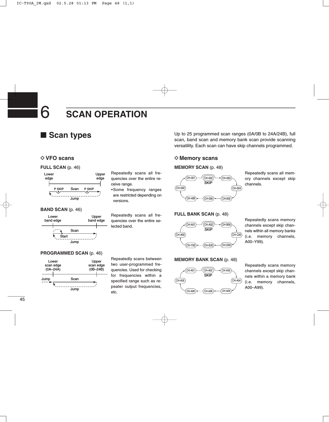
![466SCAN OPERATIONyySCAN OPERATION■VFO scanThe following scans are available for the VFO scan.FULL SCANRepeatedly scans all frequencies over the entire receiverange.•Some frequency ranges are restricted depending on versions.BAND SCANRepeatedly scans all frequencies over the entire selectedband. PROGRAMMED SCANRepeatedly scans between two user-programmed frequen-cies. Used for checking for frequencies within a specifiedrange such as repeater output frequencies, etc. Skip frequencies are not scanned when the frequency skipfunction is in use. (“P SKIP” appears)If the same frequencies are programmed into a pair ofscan edges, programmed scan does not start.For programmed scan, scan edges must be programmedin advance. Program scan edges in the same manner ofprogramming a memory channel. (p. 37)qSelect VFO mode with [VFO].wPush [5 SKIP] for 1 sec. to toggle the frequency skip func-tion ON or OFF.•“P SKIP” appears when the frequency skip function is turned ON.eSet the squelch level, if desired.rWhile pushing [MODE SCAN], rotate [DIAL] to select thedesired scan range.•“ALL” for full scan, “BAND” for band scan or “PROG 0–24” forprogrammed scan.tRelease [MODE SCAN] to start the scan.•Decimal point flashes while scanning.•“P SKIP” flashes when the frequency skip function is turned ON.•To change the scanning direction, rotate [DIAL].•If the pocket beep or DTCS beep function is activated, the trans-ceiver automatically selects the tone squelch or DTCS squelchfunction when a scan starts.yTo stop the scan, push [VFO].FM SKIPPFull scan Band scanProgrammed scan Scanning exampleFlashes while scanning.IC-T90A_IM.qxd 02.5.28 01:13 PM Page 49 (1,1)](https://usermanual.wiki/ICOM-orporated/IC-T90A/User-Guide-257988-Page-51.png)
![476SCAN OPERATION■Frequency skip functionUnwanted frequencies can be skipped and programmed asskip channels when full scan, band scan or programmed scanis pausing.qStart a VFO scan. (p. 46)wWhile receiving an unwanted signal and scan pauses,push [5 SKIP] for 1 sec. to program the received frequencyas a skip frequency.•The transceiver emits 3 beeps and the scan resumes.•Non-programmed memory channels (blank channels) are usedfor skip frequency programming in reverse sequence.•Do not release [5 SKIP] before 1 sec., otherwise, scan stops andthe transceiver enters frequency setting condition.To scan the skip frequency after programming, cancel theskip information or clear the memory channel. (p. 43)■Skip channel settingMemory channels can be set to be skipped for memory skipscan. In addition, memory channels can be set to be skippedfor both memory skip scan and frequency skip scan. Theseare useful to speed-up the scan interval.qSelect memory mode with [MR].wRotate [DIAL] to select memory channel to set the skip in-formation.ePush [5 SKIP] for 1 sec. one or more times to select con-dition.•“OFF” for no skipping of channels, “SKIP” for memory skip scanor “P SKIP” for frequency skip scan and memory skip scan.“P SCAN” setting is effective when the frequency skip func-tion is turned ON. (p. 46)FM SKIPPSkip indicationFM SKIPPFM SKIPPPush [5 SKIP] for 1 sec. to programthe frequency as a skip frequency.Blank channels are used in reverse sequence.Flashes while scanning.When scan pauses.IC-T90A_IM.qxd 02.5.28 01:13 PM Page 50 (1,1)](https://usermanual.wiki/ICOM-orporated/IC-T90A/User-Guide-257988-Page-52.png)
![486SCAN OPERATIONyySCAN OPERATION■Memory scanMemory scan repeatedly scans all memory channels exceptskip channels.qSelect memory mode with [MR].•Pushing [MR] toggles the memory channel and memory bank in-dications.wSet the squelch level, if desired.ePush [MODE SCAN] for 1 sec. to start the memory scan.•Decimal point flashes while scanning.•To change the scanning direction, rotate [DIAL].•While receiving an unwanted signal and scan pauses, push [5SKIP] for 1 sec. to set the received channel as a skip channel.rTo stop the scan, push [VFO].■Memory bank scanMemory bank scan repeatedly scans memory channels ex-cept skip channels within all memory banks or a memorybank.qSelect memory bank mode with [MR].•Pushing [MR] toggles the memory channel and memory bank in-dications.•Program 2 or more memory channels to a memory bank in ad-vance.wSet the squelch level, if desired.eFor the memory bank scan, push [BAND] to select the de-sired memory bank.rWhile pushing [MODE SCAN], rotate [DIAL] to select thedesired scan range.•“ALL” for full bank scan or “BANK” for memory bank scan.tRelease [MODE SCAN] to start the memory scan.•Decimal point flashes while scanning.•To change the scanning direction, rotate [DIAL].yTo stop the scan, push [VFO].FM SKIPPFM SKIPPWScanning example Scanning exampleFull bank scan Memory bank scanFlashes while scanning.Flashes while scanning.FM SKIPPFlashes while scanning.IC-T90A_IM.qxd 02.5.28 01:13 PM Page 51 (1,1)](https://usermanual.wiki/ICOM-orporated/IC-T90A/User-Guide-257988-Page-53.png)
![496SCAN OPERATION■Scan notesDSquelch settingScanning stops when the squelch opens. Make sure thesquelch is set to the threshold point or desired squelch level.➥Rotate the tuning dial while pushing [SQL] to select auto-matic squelch (AUTO) or a level (1–9) where the noise ismuted. (p. 22)DTuning dial while scanning ➥Scan starts in the upward direction. To change the scan-ning direction, rotate [DIAL] clockwise or counterclockwise. ➥Rotating [DIAL] while pausing a scan resumes the scanmanually.DTuning step while scanning Tuning steps while scanning becomes the selected tuningstep. Reset the tuning step before scanning, if necessary. (p. 13)DSkip functionMemory channels can be set to be skipped for memory skipscan. In addition, memory channels can be set to be skippedfor both memory skip scan and frequency skip scan. Theseare useful to speed-up the scan interval. (p. 48)DWhen receiving a signalThe scan pauses according to the scan pause time (default:10 sec.). It can be selected as a pause or timer scan (2–20 sec.) in set mode. (p. 58)The scan restarts after a signal disappears according to theresume time (default: 2 sec.). It can be selected to 0–5 sec. or‘hold’(indefinitely) in set mode. (p. 58)DScan stop beepA beep sounds when a scan stops to confirm the scan de-tects a signal. This function can be turned ON or OFF in ex-panded set mode 1. (p. 62)DScan stop LEDThe keypad backlighting flashes when a scan stops to con-firm the scan detects a signal. This function can be turned ONor OFF in expanded set mode 1. (p. 62)DReceive indicator ON/OFFThe receive indicator can be turned ON or OFF in set mode.(p. 59)IC-T90A_IM.qxd 02.5.28 01:13 PM Page 52 (1,1)](https://usermanual.wiki/ICOM-orporated/IC-T90A/User-Guide-257988-Page-54.png)
![507PRIORITY WATCH■Priority watch typesPriority watch checks for signals on a frequency every 5 sec.while operating on a VFO frequency or scanning. The trans-ceiver has 6 priority watch types to suit your needs.The watch resumes according to the selected scan resumecondition. See p. 58 for details.MEMORY or CALL CHANNEL WATCHWhile operating on a VFO frequency, priority watch checksfor a signal in the selected memory or call channel every 5sec.•A memory channel with skip information can be watched.MEMORY SCAN WATCHWhile operating on a VFO frequency, priority watch checksfor signals in each memory channel in sequence.•The memory skip function is useful to speed up the scan.VFO SCAN with MEMORY or CALL CHANNEL WATCHWhile scanning in VFO mode, priority watch checks for sig-nals in the selected memory or call channel every 5 sec.VFO SCAN with MEMORY SCAN WATCHWhile scanning in VFO mode, priority watch checks for sig-nals in memory channels every 5 sec.If the pocket beep function is activated, the transceiver au-tomatically selects the tone squelch function when prioritywatch starts.■Priority alertYou can be alerted with beeps and a flashing “S,” when apriority watch detects a signal on the watching frequency.qPush [8 SET] for 1 sec. to enter set mode.wRotate [DIAL] until “PRIO” appears.ePush [8 SET] to select the priority watch item.rRotate [DIAL] to select the priority alert item. (“BELL”)tPush [VFO] to exit set mode and start the priority watch.uuPRIORITY WATCHIC-T90A_IM.qxd 02.5.28 01:13 PM Page 53 (1,1)](https://usermanual.wiki/ICOM-orporated/IC-T90A/User-Guide-257988-Page-55.png)
![517PRIORITY WATCH■Priority watch operationDMemory channel watchWhile operating on a VFO frequency, priority watch checksfor a signal in the selected memory channel every 5 sec.•A memory channel with skip information can be watched.qSelect VFO mode; then, set an operating frequency.wSelect the desired memory channel.ePush [8 SET] for 1 sec. to enter set mode.rRotate [DIAL] until “PRIO” appears.tPush [8 SET] to select the priority watch item.yRotate [DIAL] to select the priority watch (“ON”) or prioritywatch with alert (“BELL”).uPush [VFO] to exit set mode and start the priority watch.•The transceiver checks the memory channel frequency every 5 sec.•The watch resumes according to the selected scan resume con-dition. (p. 58)iPush [VFO] while the display shows the VFO frequency tostop the watch.PRIOFMPRIOFM SKIPPChecks for a signal in the selected memory channel every 5 sec.While operating on a VFO frequencyThe watch stops on the selectedchannel when a signal is received.FMPRIOSKIPP[VFO][DIAL][8 SET]Priority watch itemPriority watch with alertPush [VFO] to start.IC-T90A_IM.qxd 02.5.28 01:13 PM Page 54 (1,1)](https://usermanual.wiki/ICOM-orporated/IC-T90A/User-Guide-257988-Page-56.png)
![527PRIORITY WATCHDVFO scan with memory channel watchWhile scanning in VFO mode, priority watch checks for sig-nals in the selected memory channel every 5 sec.•A memory channel with skip information can be watched.qSelect the desired memory channel to be watched.wSelect VFO mode.ePush [MODE SCAN] for 1 sec. to start a VFO scan. (fullscan, band scan or programmed scan)rPush [8 SET] for 1 sec. to enter set mode.tRotate [DIAL] until “PRIO” appears.yPush [8 SET] to select the priority watch item.uRotate [DIAL] to select the priority watch (“ON”) or prioritywatch with alert (“BELL”).iPush [VFO] to exit set mode and start the priority watch.oPush [VFO] while the display shows the VFO frequency tostop the VFO scan and priority watch.DMemory scan watchWhile operating on a VFO frequency, priority watch checksfor a signal in memory channels every 5 sec.qSelect VFO mode; then, set an operating frequency.wSelect memory mode.ePush [MODE SCAN] for 1 sec. to start a memory scan.rPush [8 SET] for 1 sec. to enter set mode.tRotate [DIAL] until “PRIO” appears.yPush [8 SET] to select the priority watch item.uRotate [DIAL] to select the priority watch (“ON”) or prioritywatch with alert (“BELL”).iPush [VFO] to exit set mode and start the priority watch.oPush [VFO] while the display shows the VFO frequency tostop the watch.CH-000CH-499CH-400CH-300CH-200CH-100CH-006CH-005CH-004CH-003CH-002CH-001Memory scanVFO frequency 5 sec.Pauses when a signal is received in Mch.Watches Mch while operating on VFO.FM SKIPPPRIOVFO scanMemory channel5 sec.Watches Mch while VFO scanning.Pauses when a signal is received in Mch.FMPRIO145.100145.120145.140145.200145.220145.240145.26051.000850.000433.500433.000145.280uuPRIORITY WATCHIC-T90A_IM.qxd 02.5.28 01:13 PM Page 55 (1,1)](https://usermanual.wiki/ICOM-orporated/IC-T90A/User-Guide-257988-Page-57.png)
![537PRIORITY WATCHDVFO scan with memory scan watchWhile scanning in VFO mode, priority watch checks for sig-nals in memory channels every 5 sec.qSelect memory mode.wPush [MODE SCAN] for 1 sec. to start a memory scan.•Start the memory scan first, otherwise, memory scan watch doesnot start.ePush [8 SET] for 1 sec. to enter set mode.rRotate [DIAL] until “PRIO” appears.tPush [8 SET] to select the priority watch item.yRotate [DIAL] to select the priority watch (“ON”) or prioritywatch with alert (“BELL”).uPush [VFO] to exit set mode and start the memory scanwatch.iPush [MODE SCAN] for 1 sec. to start a VFO scan. (fullscan, band scan or programmed scan)•VFO scan with memory scan watch is now activated.•The scan or watch pauses when a signal is received on a VFOfrequency or watching memory channels.oPush [VFO] while the display shows the VFO frequency tostop the VFO scan and priority watch.DCall channel watchWhile operating on a VFO frequency, priority watch checksfor a signal in the selected call channel every 5 sec.qSelect VFO mode; then, set an operating frequency.wPush [CALL/TV] to select call channel mode.eRotate [DIAL] to select the desired call channel.rPush [8 SET] for 1 sec. to enter set mode.tRotate [DIAL] until “PRIO” appears.yPush [8 SET] to select the priority watch item.uRotate [DIAL] to select the priority watch (“ON”) or prioritywatch with alert (“BELL”).iPush [VFO] to exit set mode and start the priority watch.oPush [VFO] while the display shows the VFO frequency tostop the watch.FMPRIOSKIPPFMPRIOChecks for a signal in the selected call channel every 5 sec.While operating on a VFO frequencyThe watch stops on the selectedchannel when a signal is received.IC-T90A_IM.qxd 02.5.28 01:13 PM Page 56 (1,1)](https://usermanual.wiki/ICOM-orporated/IC-T90A/User-Guide-257988-Page-58.png)
![547PRIORITY WATCHDVFO scan with call channel watchWhile scanning in VFO mode, priority watch checks for sig-nals in the selected call channel every 5 sec.qSelect VFO mode.wPush [CALL/TV] to select call channel mode.eRotate [DIAL] to select the desired call channel.rPush [8 SET] for 1 sec. to enter set mode.tRotate [DIAL] until “PRIO” appears.yPush [8 SET] to select the priority watch item.uRotate [DIAL] to select the priority watch (“ON”) or prioritywatch with alert (“BELL”).iPush [VFO] to exit set mode and start the priority watch.oPush [MODE SCAN] for 1 sec. to start a VFO scan. (fullscan, band scan or programmed scan)!0 Push [VFO] while the display shows the VFO frequency tostop the VFO scan and priority watch.VFO scanCall channel5 sec.Watches call Ch while VFO scanning.Pauses when a signal is received in call Ch.PRIOFM145.100145.120145.140145.200145.220145.240145.26051.000850.000433.500433.000145.280uuPRIORITY WATCHIC-T90A_IM.qxd 02.5.28 01:13 PM Page 57 (1,1)](https://usermanual.wiki/ICOM-orporated/IC-T90A/User-Guide-257988-Page-59.png)
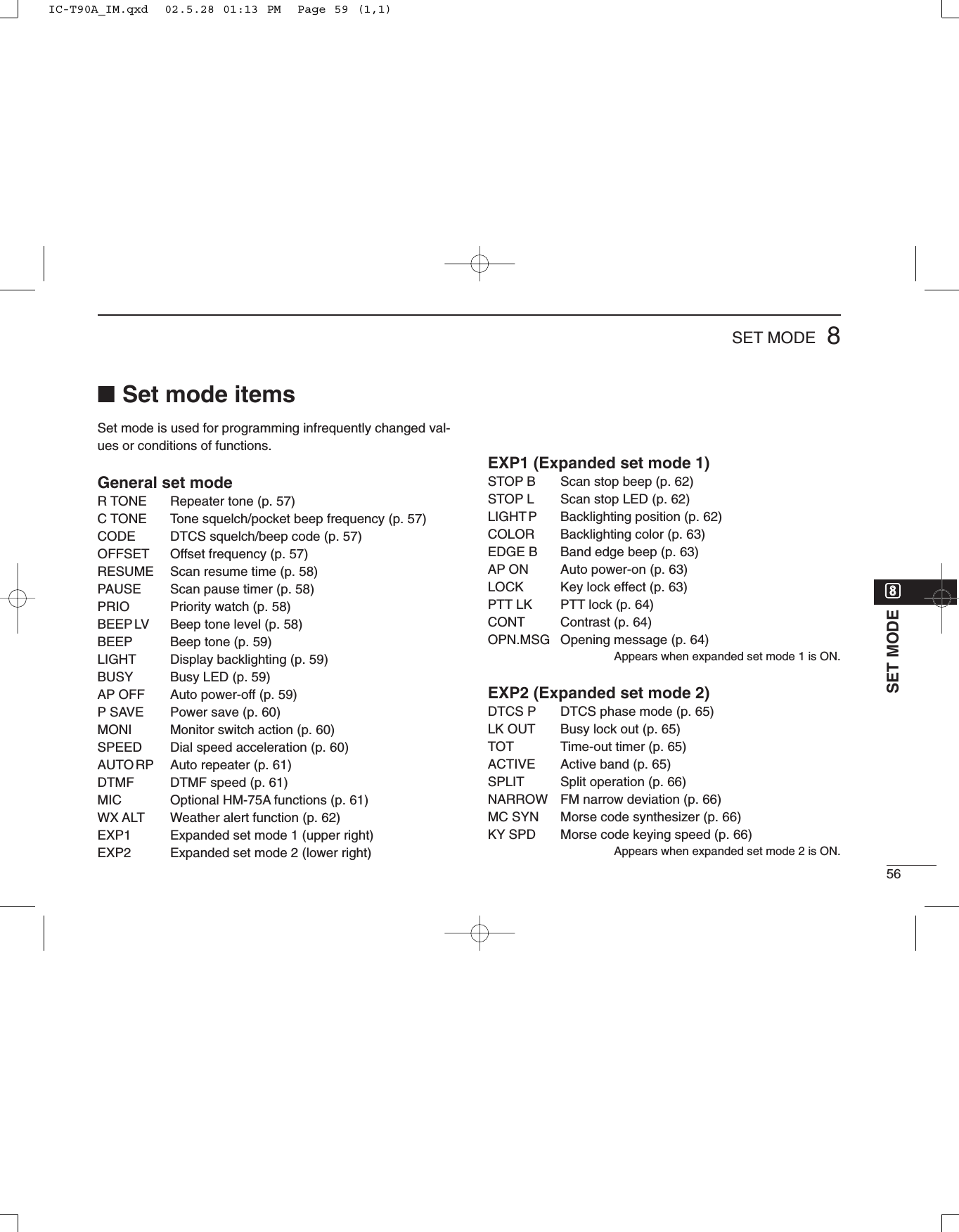
![558SET MODE■Set modeSet mode is used for programming in-frequently changed values or conditionsof functions.In addition, this transceiver has 2 ex-panded set modes which are used forprogramming more infrequentlychanged values or conditions of func-tions. When turning the expanded setmodes OFF, only half of the set modeitems are displayed for simple opera-tion.DEntering set modeqPush [8 SET] for 1 sec. to enter setmode.wRotate [DIAL] until the desired itemappears.ePush [8 SET] to select the set modeitem.rRotate [DIAL] to select a set modeitem.tPush [VFO] to exit set mode or push[8 SET] then rotate [DIAL] to selectanother set mode item.DExpanded set modeON/OFFqPush [8 SET] for 1 sec. to enter setmode.wRotate [DIAL] until “EXP1” or “EXP2”appears.ePush [8 SET] to select an expandedset mode.rRotate [DIAL] to turn the expandedset mode ON or OFF.tPush [8 SET] then rotate [DIAL] toselect a set mode item in the ex-panded set mode, or push [VFO] toexit set mode. SKIPPFM[VFO][8 SET][DIAL]IC-T90A_IM.qxd 02.5.28 01:13 PM Page 58 (1,1)](https://usermanual.wiki/ICOM-orporated/IC-T90A/User-Guide-257988-Page-60.png)
![578SET MODE•Repeater tone (R TONE)Selects tone encoder frequency for accessing a repeater, etc.from one of 50 available tone frequencies. •67.0–254.1 Hz (50 tones):88.5 Hz (default)•Tone squelch frequency (C TONE)Selects tone squelch or pocket beep frequency from one of50 available tone frequencies. •67.0–254.1 Hz (50 tones):88.5 Hz (default)[Repeater/Tone squelch tone table]•DTCS squelch code (CODE)Selects DTCS squelch code from one of 104 available codes.•023–754 (104 codes):023 (default)[DTCS code table]•Offset frequency (OFFSET)Sets the offset frequency for duplex(repeater) operation within0–159.995 MHz range.The offset frequency changesaccording to the selected tuningsteps. (p. 18)02302502603103203604304705105305406507107207307411411511612212513113213414314515215515616216517217420521222322522624324424524625125225526126326526627127430631131532533133234334635135636436537141141241342343143244544645245445546246446546650350651652352653254656560661262462763163265466266470371272373173273474375467.069.371.974.477.079.782.585.488.591.594.897.4100.0103.5107.2110.9114.8118.8123.0127.3131.8136.5141.3146.2151.4156.7159.8162.2165.5167.9171.3173.8177.3179.9183.5186.2189.9192.8196.6199.5203.5206.5210.7218.1225.7229.1233.6241.8250.3254.1IC-T90A_IM.qxd 02.5.28 01:13 PM Page 60 (1,1)](https://usermanual.wiki/ICOM-orporated/IC-T90A/User-Guide-257988-Page-62.png)
![608SET MODE•Power save (P SAVE)The power save function reduces the current drain to con-serve battery power. This item sets the power save dutycycle—the ratio of receive circuit on to receive circuit off whilestanding by. The duty cycle can be set to automatic (default),1:1, 1:4, 1:8, 1:16 or OFF. “AUTO” selects “1:4” duty ratio when receiving no signal for 5sec., then “1:8” 60 sec. after that.When “AUTO” is selected, the power save automaticallyturns OFF while operating with an external DC power(10–11.5 V DC)For packet operation, the power save should be turnedOFF to receive reliable packet data. •Monitor switch action (MONI)The monitor switch can be set as a ‘sticky’switch. When setto the sticky condition, each push of [SQL] toggles the moni-tor function on and off.•PUSH Set the monitor switch tonormal. (default)•HOLD Set the monitor switch tosticky switch.•Dial speed acceleration (SPEED)The dial speed acceleration automatically speeds up the tun-ing dial speed when rotating the [DIAL] rapidly.•ON The dial speed accelerationis turned ON. (default)•OFF The dial speed accelerationis turned OFF.iiSET MODEIC-T90A_IM.qxd 02.5.28 01:13 PM Page 63 (1,1)](https://usermanual.wiki/ICOM-orporated/IC-T90A/User-Guide-257988-Page-65.png)
![•Auto repeater (AUTO RP)The auto repeater function automatically turns ON or OFF theduplex operation with specified shift direction and tone en-coder, when the operating frequency falls within or outside ofthe general repeater output frequency range. U.S.A. version:•ONLYActivates duplex only. (default)•TONE Activates duplex and tone.•OFF Deactivates the function.Korea version:•ON Activates duplex and tone. (de-fault)•OFF Deactivates the function.•DTMF speed (DTMF)The rate at which DTMF memories send individual DTMFcharacters can be set to accommodate operating needs.DISPLAY INTERVAL SPEED100 100 msec. 5.0 cps200 200 msec. 2.5 cps300 300 msec. 1.6 cps500 500 msec. 1.0 cpscps=characters/sec.•Optional HM-75A functions MICMicrophone simple mode is used to change the function as-signments for switches on the optional HM-75A REMOTE CON-TROL MICROPHONE.•NORM-1: (default)[A] Selects band.[B] Toggles VFO and memory.[Y] [UP][Z] [DOWN]•NORM-2: [A] Toggles monitor function.[B] Toggles VFO and memory.[Y] [UP][Z] [DOWN]•SIMPLE: [A] Toggles monitor function.[B] Selects call channel C0.[Y] Selects memory Ch 000.[Z] Selects memory Ch 001.VFO mode cannot be selected via the microphone whenSIMPLE mode is selected.618SET MODEIC-T90A_IM.qxd 02.5.28 01:13 PM Page 64 (1,1)](https://usermanual.wiki/ICOM-orporated/IC-T90A/User-Guide-257988-Page-66.png)
![638SET MODE•Backlighting color (COLOR)Selects backlighting color between green, orange or red.•Turn the expanded set mode 1 ON in advance.•GREEN Green backlighting color.(default)•ORANGE Orange backlighting color. •RED Red backlighting color. •Band edge beep (EDGE B)Turns band edge beep ON or OFF. The band edge beepsounds when the operating frequency changes across theband edge.•Turn the expanded set mode 1 ON in advance.•ON The band edge beep is turnedON. •OFF The band edge beep is turnedOFF. (default)•Auto power ON (AP ON)Turns the transceiver power ON after 30 min. to 24 hrs. in 30min. steps.•Turn the expanded set mode 1 ON in advance.When operating with batterypack or case and the battery isexhausted, auto power-on doesnot function. •Key lock effect (LOCK)While the lock function is ON, [PWR], [PTT], [SQL], [Y]/[Z]and [CALL/TV LOCK] can still be accessed. Accessibleswitches can be set to 1 of 4 groups.•Turn the expanded set mode 1 ON in advance.•NORMAL [PWR], [PTT], [SQL]and [Y]/[Z] are acces-sible.•NO SQL [PWR], [PTT] and[SQL] are accessible.•NO VOL [PWR], [PTT] and[Y]/[Z] are accessible.•ALL [PWR] and [PTT] are accessible.IC-T90A_IM.qxd 02.5.28 01:13 PM Page 66 (1,1)](https://usermanual.wiki/ICOM-orporated/IC-T90A/User-Guide-257988-Page-68.png)
![658SET MODE•DTCS phase mode (DTCS P)Selects DTCS phase mode.•Turn the expanded set mode 2 ON in advance.•BOTH N Normal phases are used forboth Tx and Rx. (default)•TN-RR Normal phase is used forTx; Reverse phase for Rx.•TR-RN Reverse phase is used forTx; Normal phase for Rx.•BOTH R Reverse phases are usedfor both Tx and Rx.•Busy lock out (LK OUT)Turns the busy lockout function ON and OFF. This functioninhibits transmission while receiving a signal or when thesquelch is open.•Turn the expanded set mode 2 ON in advance.•ON The busy lockout is turned ON. •OFF The busy lockout is turnedOFF. (default)•Time-out timer (TOT)To prevent accidental prolonged transmission, etc., the trans-ceiver has a time-out timer. This timer cuts a transmissionOFF after 1, 3, 5 or 10 min. of continuous transmission. Thistimer can be cancelled.•Turn the expanded set mode 2 ON in advance.Approx. 10 sec. before the time-out timer is activated, thetransceiver emits a beep tone as a warning.•OFF The time-out timer is turnedOFF. (default)•1–10 The transmission is cut OFFafter the set period elapses.•Active band (ACTIVE)Allows continuous frequency selection of the operating fre-quency across all bands.•ALL The operating frequencycan be selected continu-ously. (default)•SINGLE The operating frequencycan be selected withinthe current band. Push[BAND] for band selec-tion in this case.IC-T90A_IM.qxd 02.5.28 01:13 PM Page 68 (1,1)](https://usermanual.wiki/ICOM-orporated/IC-T90A/User-Guide-257988-Page-70.png)
![668SET MODE•Split operation (SPLIT)Turns the split operation ON or OFF. Split frequency opera-tion allows you to transmit and receive on two different fre-quencies. Split frequency operation uses 2 frequencies, onein VFO A and the other in VFO B.•Turn the expanded set mode 2 ON in advance.•ON The split operation is turnedON. ‘SPA’appears for VFO A;‘SPB’appears for VFO B.•OFF The split operation is turnedOFF. (default)•FM narrow deviation (NARROW)Selects the maximum FM deviation for normal or narrow FMmode on transmit mode.•ON Selects the narrow FM devia-tion for FM mode.•OFF Selects the normal FM devia-tion for FM mode. (default)•Morse code synthesizer (MC SYN)The transceiver announces the operating frequency or TVchannel number in Morse code.•Turn the expanded set mode 2 ON in advance.•ON The Morse code synthesizeris turned ON. •OFF The Morse code synthesizeris turned OFF. (default)Turning power ON while pushing[CALL/TV] also toggles theMorse code synthesizer ON or OFF. •Morse code keying speed (KY SPD)The keying speed of the Morse code synthesizer can be ad-justed within 10 to 25 WPM for your convenience. •Turn the expanded set mode 2 ON in advance.•10–25 WPM in 5 WPM steps20 WPM (default)iiSET MODEIC-T90A_IM.qxd 02.5.28 01:13 PM Page 69 (1,1)](https://usermanual.wiki/ICOM-orporated/IC-T90A/User-Guide-257988-Page-71.png)
![679OTHER FUNCTIONS■Programming a DTMF codeDTMF codes are used for autopatching, accessing repeaters,controlling other equipment, etc. The transceiver has 10DTMF memory channels (D0–D9) for storage of often-usedDTMF codes of up to 16 digits.qPush [• DTMF.M] for 1 sec. to enter DTMF memory.wRotate [DIAL] to select the desired DTMF memory chan-nel.•“T-CALL” appears when a 1750 Hz tone burst signal is selected.(p. 29)ePush [• DTMF.M] for 1 sec. to enter programming mode.•Previously programmed DTMF code is cleared.rPush the desired keys to input the characters.•[VFO] inputs “A,”[MR] inputs “B,”[CALL/TV] inputs “C,”[BAND]inputs “D,” [•] inputs “M” (E) and [MODE] inputs “F” (#).•Up to 16 digits can be programmed.tRepeat runtil the desired code is input.yPush [SQL] or [PTT] to program the DTMF code and exitprogramming mode.•Entering 16the digit automatically exits the programming mode.Next display appears when 7th digit is input.The display returns to 1st display when 16th digit is input.Programming modeDTMF memorychannelBlank channelindicationIC-T90A_IM.qxd 02.5.28 01:13 PM Page 70 (1,1)](https://usermanual.wiki/ICOM-orporated/IC-T90A/User-Guide-257988-Page-72.png)
![689OTHER FUNCTIONS■Transmitting a DTMF codeDTransmitting from DTMF memoryThe selected DTMF code is transmitted at each push of the[SQL] switch while transmitting.The rate at which DTMF memories send individual DTMFcharacters can be set in set mode. (p. 56)qSet the desired frequency.wPush [• DTMF.M] for 1 sec. to enter DTMF memory.eRotate [DIAL] to select the desired DTMF memory chan-nel.rPush [VFO] to exit DTMF memory.tWhile pushing [PTT], push [SQL] to transmit the selectedDTMF code.DTransmitting a DTMF code directlyDTMF code can be transmitted via keypad directly whiletransmitting.qSet the desired frequency.wWhile pushing [PTT], push the desired keys to transmit theDTMF code.•[VFO] transmits “A,”[MR] transmits “B,”[CALL/TV] transmits “C,”[BAND] transmits “D,” [•] transmits “E” (M) and [MODE] transmits“F” (#).FM SKIPP[PTT]DTMF code is not displayed.[SQL][PTT][• DTMF.M][DIAL][VFO]DTMF code is displayed6 digits at a time.ooOTHER FUNCTIONSIC-T90A_IM.qxd 02.5.28 01:13 PM Page 71 (1,1)](https://usermanual.wiki/ICOM-orporated/IC-T90A/User-Guide-257988-Page-73.png)
![699OTHER FUNCTIONS■Clearing a DTMF memoryAn unwanted DTMF memory can be cleared (erased).qPush [• DTMF.M] for 1 sec. to enter DTMF memory mode.wRotate [DIAL] to select the desired DTMF memory chan-nel to be cleared.ePush [• DTMF.M] for 1 sec. to enter programming modeand clear the selected DTMF memory channel.•The DTMF memory channel is cleared.rPush [SQL] or [PTT] to exit programming mode.■Confirming a DTMF memoryThe DTMF memory can be confirmed with DTMF tone.qPush [• DTMF.M] for 1 sec. to enter DTMF memory mode.wRotate [DIAL] to select the desired DTMF memory chan-nel.ePush [SQL] to confirm the DTMF memory contents.•The display returns to frequency indication after confirmation.FM SKIPP[SQL][• DTMF.M][DIAL] DTMF code is displayed6 digits at a time.The display returns tofrequency indication.[SQL][PTT][• DTMF.M][DIAL][VFO]Select DTMF memory to be cleared.DTMF programming modeThe DTMF memory becomes blank.IC-T90A_IM.qxd 02.5.28 01:13 PM Page 72 (1,1)](https://usermanual.wiki/ICOM-orporated/IC-T90A/User-Guide-257988-Page-74.png)
![709OTHER FUNCTIONS•Subaudible (repeater) toneSome repeaters require subaudibletones to be accessed. Subaudibletones are superimposed over your nor-mal signal and must be set in advance.•Tone and DTCS squelchesThe tone squelch (CTCSS) or DTCSsquelch opens only when receiving asignal containing a matching subaudi-ble tone or DTCS code, respectively.You can silently wait for calls fromgroup members using the same tone orcode. Separate tone frequencies canbe set for repeater and tonesquelch/pocket beep operation.•Pocket and DTCS beepThese functions use subaudible tonesor DTCS code for calling and can beused as a “common pager” to informyou that someone has called while youwere away from the transceiver. Samecode is used for DTCS squelch andbeep.DSetting subaudible tones forrepeater or tone squelchqPush [8 SET] for 1 sec. to enter setmode.wRotate [DIAL] until “R TONE” (re-peater tone) or “C TONE” (CTCSStone) appears.ePush [8 SET].rRotate [DIAL] to select the desiredrepeater or CTCSS tone.•Each operating band and each memorychannel have independent settings.tPush [VFO] to exit set mode.DSetting DTCS code forDTCS squelch or beepqPush [8 SET] for 1 sec. to enter setmode.wRotate [DIAL] until “CODE” appears.ePush [8 SET].rRotate [DIAL] to select the desiredDTCS code.•Each operating band and each memorychannel have independent settings.tPush [VFO] to exit set mode.DTCS phase mode can be selectedin expanded set mode 2. (p. 60)■Tone frequency and DTCS codeooOTHER FUNCTIONSIC-T90A_IM.qxd 02.5.28 01:13 PM Page 73 (1,1)](https://usermanual.wiki/ICOM-orporated/IC-T90A/User-Guide-257988-Page-75.png)
![719OTHER FUNCTIONS■Tone/DTCS squelchqSet the desired operating frequency, CTCSS tone andDTCS code.wPush [2 TONE] for 1 sec. one or more times to activate thetone or DTCS squelch. (T SQL or DTCS)•Subaudible tone encoder “T,” tone squelch “T SQL,” pocket beep“T SQLS,” DTCS squelch “DTCS,” DTCS beep “SDTCS”and no tone operation are activated in order.•Rotating [DIAL] while pushing [2 TONE] also selects the tonefunctions.eOperate the transceiver in the normal way.rWhen the received signal includes a matching tone,squelch opens and the signal can be heard.•When the received signal’s tone does not match, tone squelchdoes not open, however, the S-indicator shows signal strength.•To open the squelch manually, push and hold [SQL].■Pocket beep functionqSet the desired operating frequency.wSet the desired CTCSS tone or DTCS code.ePush [2 TONE] for 1 sec. one or more times to activate thepocket beep or DTCS beep. (T SQLSor SDTCS)•Rotating [DIAL] while pushing [2 TONE] also selects the tonefunctions.rWhen a signal with the correct tone or code is received,the transceiver emits beep tones for 30 sec. and flashes“S”.tPush [PTT] to answer or push [SQL] to stop the beeps andflashing.➲CONVENIENTStore subaudible tone frequencies, DTCS code, DTCS phasemode and tone/DTCS squelch ON/OFF settings in memories(call) for easy recall.FM DTCS SKIPPFM SQL SKIPTPPocket beepby CTCSS dodePocket beepby DTCS codeFM SKIPPFM SKIPTPFM SQL SKIPTPFM SQL SKIPTPFM DTCS SKIPPFM DTCS SKIPPNo tone operationSubaudible tone encoderTone squelchPocket beepDTCS beepDTCS squelchIC-T90A_IM.qxd 02.5.28 01:13 PM Page 74 (1,1)](https://usermanual.wiki/ICOM-orporated/IC-T90A/User-Guide-257988-Page-76.png)
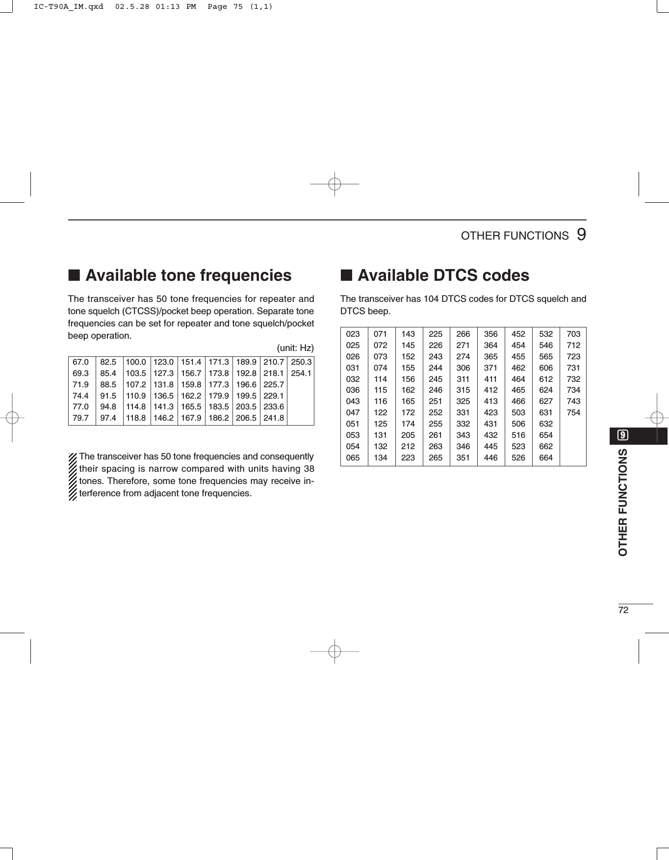
![739OTHER FUNCTIONS■Tone scanThe transceiver can detect the subaudible tone frequency andDTCS code in a received signal. By monitoring a signal thatis being transmitted on a repeater input frequency, you candetermine the tone frequency required to access the repeater.qSet the desired frequency or memory channel to bechecked for a tone frequency or DTCS code.wPush [2 TONE] for 1 sec. one or more times to activate therepeater tone, tone squelch or DTCS squelch. (T, T SQLor DTCS)•Rotating [DIAL] while pushing [2 TONE] also selects the tonefunctions.ePush [7 T.SCAN] for 1 sec. to start the tone scan.•To change the scanning direction, rotate [DIAL].rWhen the tone frequency or DTCS code is decoded, theset mode contents are programmed with the frequency orcode.•The tone scan pauses approx. 10 sec. when a tone frequency orDTCS code is detected.•The decoded tone frequency is used for the repeater tone fre-quency when the tone squelch or DTCS squelch is OFF.•The decoded tone frequency is used for the tone squelch fre-quency when the tone squelch is ON.•The decoded DTCS code is used for the DTCS code when theDTCS squelch is ON.•“CT,” “rT” or “CD” appears according to the tone setting.tPush [VFO] to stop the scan.•If the scan is cancelled before the transceiver detects the toneor code, the set mode contents are not changed.[DIAL][VFO][2 TONE][7 T.SCAN]Tone scan for tone squelchTone scan for repeater toneTone scan for DTCS squelchFlashes while scanning.Flashes while scanning.IC-T90A_IM.qxd 02.5.28 01:13 PM Page 76 (1,1)](https://usermanual.wiki/ICOM-orporated/IC-T90A/User-Guide-257988-Page-78.png)
![749OTHER FUNCTIONS■Beep tonesYou can select to have confirmation beeps sound at the pushof a switch. The output level can be adjusted within 32 levelsor to the related level of the volume. (p. 58)You can select silent operation by turning beep tones OFF.(p. 59)These can be selected in set mode.■Dial speed accelerationThe dial speed acceleration automatically speeds up the tun-ing dial speed when rotating the [DIAL] rapidly.This function can be turned ON and OFF in set mode. (p. 60)■Lock functionThe lock function prevents accidental frequency changes andaccidental function access.➥Push [CALL/TV LOCK] for 1 sec. to toggle the lock functionON and OFF.•[PWR], [VOL], [SQL] and [PTT] can still be accessed while thelock function is ON. (default)DLock function effectWhile the lock function is ON, [PWR], [VOL], [SQL] and [PTT]can still be accessed. Accessible switches can be set to 1 of 4groups in expanded set mode 1. (p. 63)•“NORMAL”: [PWR], [VOL], [SQL] and [PTT] are accessible.•“NO SQL”: [PWR], [SQL] and [PTT] are accessible.•“NO VOL”: [PWR], [VOL] and [PTT] are accessible.•“ALL”: [PWR] and [PTT] are accessible.FM SKIPPLock indicationooOTHER FUNCTIONSIC-T90A_IM.qxd 02.5.28 01:13 PM Page 77 (1,1)](https://usermanual.wiki/ICOM-orporated/IC-T90A/User-Guide-257988-Page-79.png)
![759OTHER FUNCTIONS■Morse code synthesizerThe transceiver announces the operating frequency or TVchannel number in Morse code. The keying speed can be ad-justed within 10 to 25 WPM in 5 WPM steps for your conve-nience. This can be selected in expanded set mode 2. (p. 66)➥Push [BAND] for 1 sec. forfrequency announcementwhen the Morse code syn-thesizer is turned ON.Turning power ON whilepushing [CALL/TV] alsotoggles the Morse codesynthesizer ON or OFF. ■Power saveThe power save function reduces the current drain to con-serve battery power. The power save duty cycle, the ratio of receive circuit on toreceive circuit off while standing by, can be set to automatic(default), 1:1, 1:4, 1:8, 1:16 or OFF in set mode. (p. 60)•“AUTO” selects “1:4” duty ratio when receiving no signal for 5 sec.,then “1:8” 60 sec. after that.When automatic is selected, the power save automaticallyturns OFF while operating with an external DC power sup-ply. (11.0 V DC ±5%)Circuit onCircuit off150 msec.60 sec.600 msec. 1200 msec.No signal5 sec.[PWR][BAND][CALL/TV]IC-T90A_IM.qxd 02.5.28 01:13 PM Page 78 (1,1)](https://usermanual.wiki/ICOM-orporated/IC-T90A/User-Guide-257988-Page-80.png)
![779OTHER FUNCTIONS■Weather channel operation(USA version only)There are 10 weather channels for moni-toring weather channels from the NOAA(National Oceanographic and AtmosphericAdministration) broadcasts.DDWeather channel selectionqPush [CALL/TV LOCK] one or two times to select weatherchannel mode.•“WX” and the weather channel number appear.wRotate [DIAL] to select the desired weather channel.qPush [VFO] or [MR] to return to the previous frequency.DDWeather alert functionNOAA broadcast stations transmit weather alert tones beforeimportant weather announcements. When the weather alertfunction is turned ON, the selected weather channel is moni-tored each 5 sec. for the announcement. When the alert sig-nal is detected, the “AL.T” and the WX channel are displayedalternately and sounds a beep tone until the transceiver isoperated. The previously selected (used) weather channel ischecked periodically during standby or while scanning.qSelect the desired weather channel.wTurn the weather alert function ON in set mode.➥Push [8 SET] for 1 sec. to enter set mode.➥Rotate [DIAL] to select the [WX ALT] (weather alertfunction), then push [8 SET].➥Rotate the [DIAL] to set ON.➥Push [VFO] to exit set mode.eSets the desired stand-by condition.•Selects VFO, memory or call channel.•Scan or priority watch operation can also be selected.rWhen the alert is detected, a beep sounds and the follow-ing indication will be displayed.tTurn the weather alert function OFF in set mode.[DIAL][CALL/TV LOCK]Shows above indications alternately.IC-T90A_IM.qxd 02.5.28 01:13 PM Page 80 (1,1)](https://usermanual.wiki/ICOM-orporated/IC-T90A/User-Guide-257988-Page-82.png)
![799OTHER FUNCTIONS■Cloning functionThe IC-T90A has transceiver-to-transceiver data cloning ca-pability. This function is useful when you want to copy all ofthe programmed contents from one IC-T90A to another. Anoptional OPC-474 CLONING CABLE is required.qConnect an optional OPC-474 between both [SP] jacks.wWhile pushing [8 SET] and [MR], push [PWR] for 1 sec. toenter cloning mode.•“CLONE” appears.ePush [PTT] on the “master” transceiver.•“CL OUT” appears and the signal indicator shows that cloning istaking place.rPush [PWR] for 1 sec. to turn power OFF.The optional CS-T90A CLONING SOFTWARE and the optionalOPC-478 CLONING CABLE are available to clone and editcontents with a PC (for Microsoft®Windows®95/98/ME).Microsoft®and Windows®are registered trademarks of Microsoft Corporation inthe U.S.A. and other countries.■[SP/MIC] jacksTo connect external equipment such as speaker, microphone,TNC, etc. refer to the diagram below.The center terminal of [MIC] outputs 3.2 V DC via 330 Ωregister.External speaker[SP] jackSPSPGNDø3.5 mmplug[MIC] jack33 kΩMIC MICGND External microphoneø2.5 mmplugPTT3.2 V (See below)Impedance 8 ΩImpedance 2 kΩMIC3.2VMIC GNDSP (AF OUT)REMOTESP GNDOPC-474 to [SP]to [SP]Signal indicator shows that cloning is taking place.Cloning periodCloning modeIC-T90A_IM.qxd 02.5.28 01:13 PM Page 82 (1,1)](https://usermanual.wiki/ICOM-orporated/IC-T90A/User-Guide-257988-Page-84.png)
![809OTHER FUNCTIONS■ResettingThe function display may occasionallydisplay erroneous information (e.g.when first applying power). This may becaused externally by static electricity orby other factors.If this problem occurs, turn power OFF.After waiting a few seconds, turn powerON again. If the problem persists, per-form either or both procedures below.•All resetReset the CPU before operating thetransceiver for the first time, or whenthe internal CPU malfunctions to clearand return all programmed contents totheir default settings. •Partial resetIf you want to initialize the operatingconditions (VFO frequency, VFO set-tings, set mode contents) without clear-ing the memory contents, a partialresetting function is available for thetransceiver.DAll resetqPush [POWER] for 2 sec. to turnpower OFF.wWhile pushing [BAND], [VFO] and[MR], turn power ON to reset theCPU.•“CLEAR” appears when resetting theCPU.CAUTION: Resetting the CPU re-turns all programmed contents totheir default settings.DPartial resetqPush [POWER] for 2 sec. to turnpower OFF.wWhile pushing [VFO], turn power ONto partially reset the transceiver.•Total resettingFM SKIPP[PWR][BAND][VFO][MR]ooOTHER FUNCTIONSIC-T90A_IM.qxd 02.5.28 01:13 PM Page 83 (1,1)](https://usermanual.wiki/ICOM-orporated/IC-T90A/User-Guide-257988-Page-85.png)
![8110 HM-75A REMOTE CONTROL MICROPHONEThe optional HM-75A allows you to remotely select operatingfrequencies, memory channels, etc. Remote control functions can be selected from 3 settings.This can be selected in set mode. (p. 56)The HM-75A has a lock switch on the backside to prevent ac-cidental frequency changes, etc.Be sure to turn power OFF when plugging the HM-75A inthe [SP/MIC] jacks.•NORM-1: (default)[A] Selects band.[B] Toggles VFO and memory.[Y] [UP][Z] [DOWN]•NORM-2: [A] Toggles monitor function.[B] Toggles VFO and memory.[Y] [UP][Z] [DOWN]•SIMPLE: [A] Toggles monitor function.[B] Selects call channel C0.[Y] Selects memory Ch 000.[Z] Selects memory Ch 001.VFO mode cannot be selected via the microphone whenSIMPLE mode is selected.SIMPLE mode can select only 3 channels and is useful forgroup operations during touring, etc.AOFF ONLOCKBPTT switchTransmit LEDEarphone jackMicrophoneSpeakerOPTIONALIC-T90A_IM.qxd 02.5.28 01:13 PM Page 84 (1,1)](https://usermanual.wiki/ICOM-orporated/IC-T90A/User-Guide-257988-Page-86.png)
![8211TROUBLESHOOTINGPROBLEM POSSIBLE CAUSE SOLUTION REF.No power comes ON. •The batteries are exhausted.•The battery polarity is reversed.•Replace the batteries or charge the battery pack.•Check the battery polarity.pgs. 1, 16p. 1No sound comes from thespeaker.•Volume level is too low.•Different tone is selected with tone/DTCSsquelch.•Push [Y] to a suitable level.•Check the tone using tone/DTCS scan.p. 17p. 70Transmitting isimpossible.•The batteries are exhausted.•A frequency outside of the 50/144/400MHz amateur bands is set.•Replace the batteries or charge the battery pack.•Reset the frequency inside the 50/144/400 MHzamateur bands.pgs. 13, 16p. 19, 87Tuning dial or [Z]/[Y]function is strange.•Tuning dial and [Z]/[Y] functions areexchanged.•Push [1 V↔D] for 1 sec. to cancel the function. p. 23No beeps sound. •Beep tones are turned OFF or the beeptone level is low.•Turn beep tones ON or set the beep tone level toappropriate level in set mode.pgs. 58,59No contact possible withanother station.•Different tone is selected with tone/DTCSsquelch.•Check the tone using tone scan. p. 70Receive audio isdistorted.•The operating mode is not selectedcorrectly.•Select a suitable operating mode in set mode. p. 21Desired set mode itemcannot be selected.•The desired set mode item is in expandedset mode 1 or 2.•Some set mode items can be selectedfrom VFO or memory mode only.•Turn the expanded set mode 1 or 2 ON.•Enter set mode from appropriate operating mode.p. 55pgs. 17, 1822, 27 Frequency cannot be set. •The lock function is activated.•Memory or call channel is selected.•Push [CALL/TV LOCK] for 1 sec. to cancel the function.•Push [VFO] to select VFO mode.p. 74p. 20If your transceiver seems to be malfunctioning, please checkthe following points before sending it to a service center.!!00!!11HM-75 REMOTE CONTROL MICROPHONETROUBLESHOOTINGIC-T90A_IM.qxd 02.5.28 01:13 PM Page 85 (1,1)](https://usermanual.wiki/ICOM-orporated/IC-T90A/User-Guide-257988-Page-87.png)
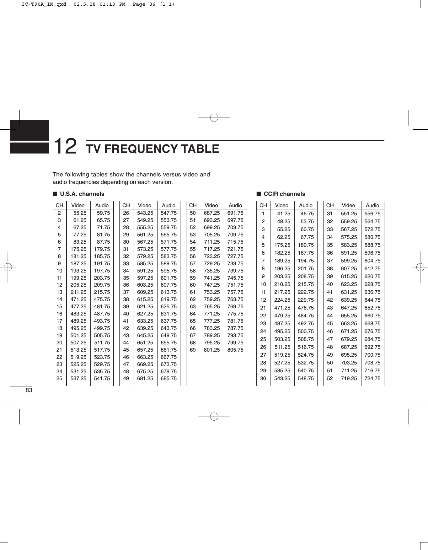
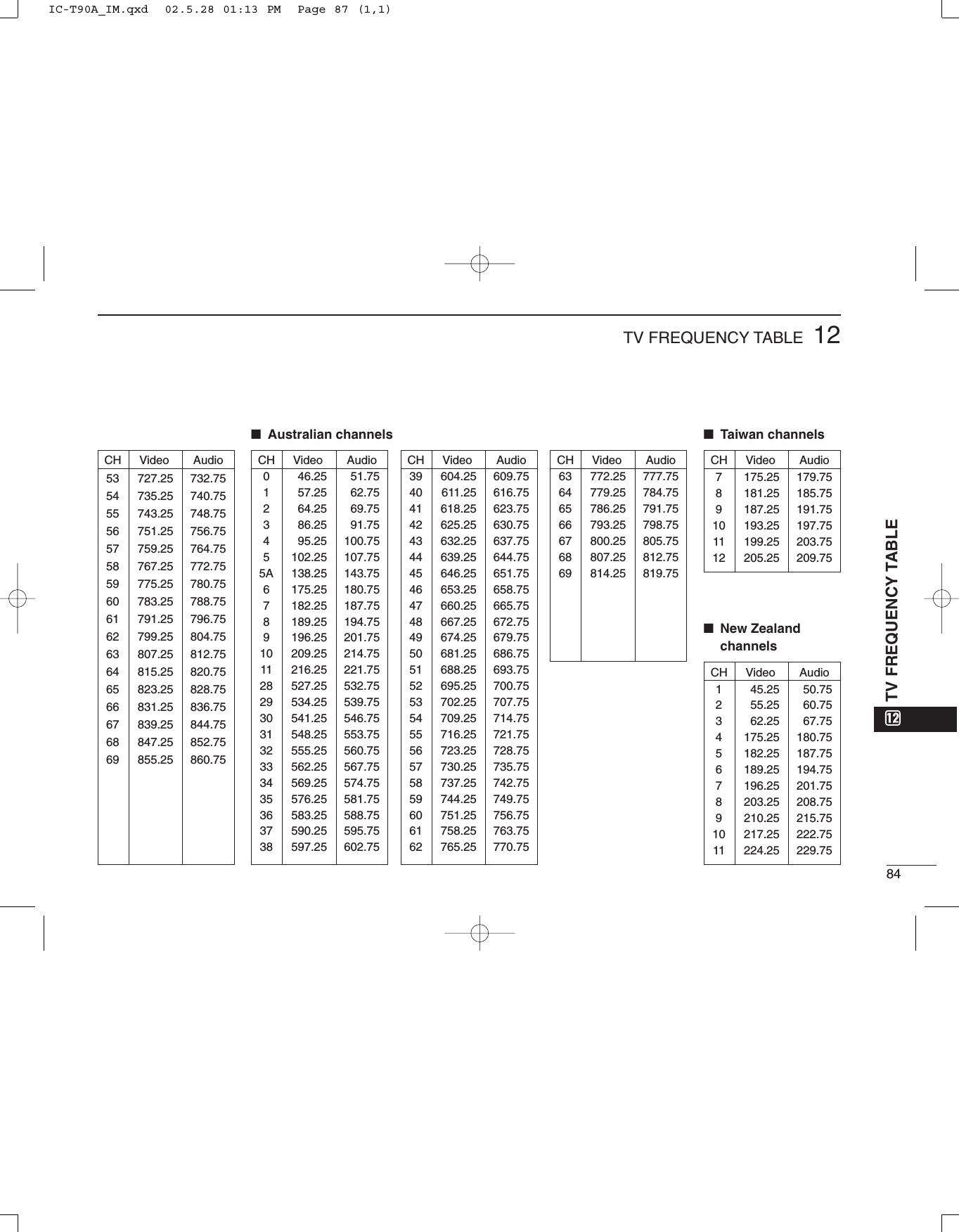
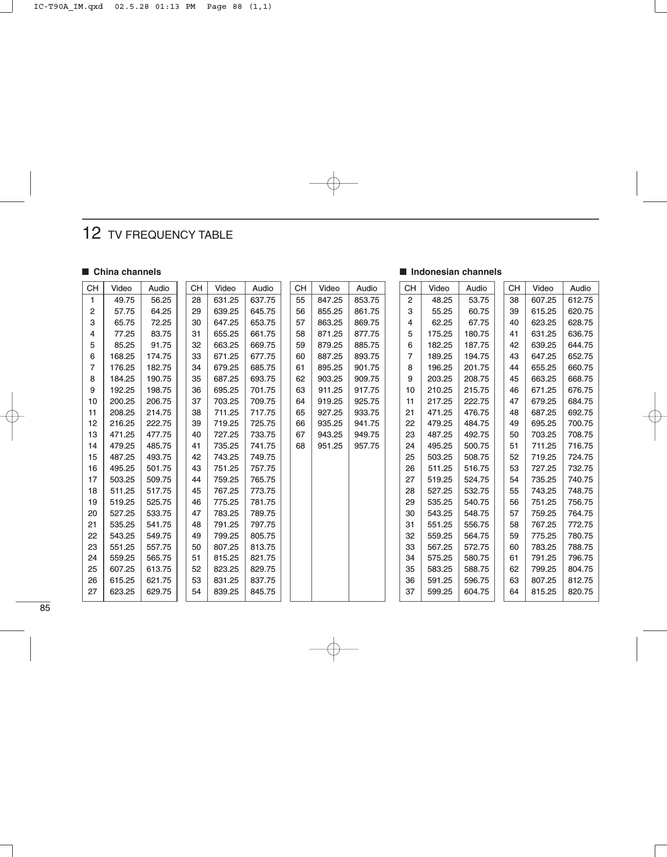
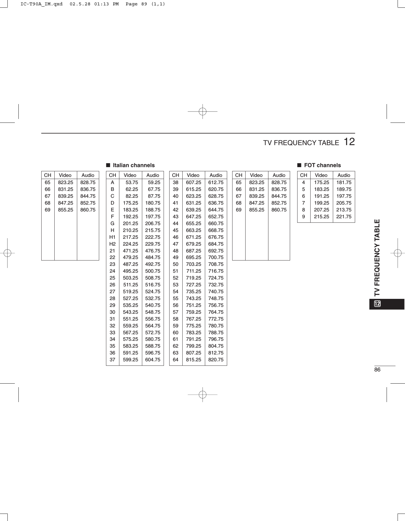
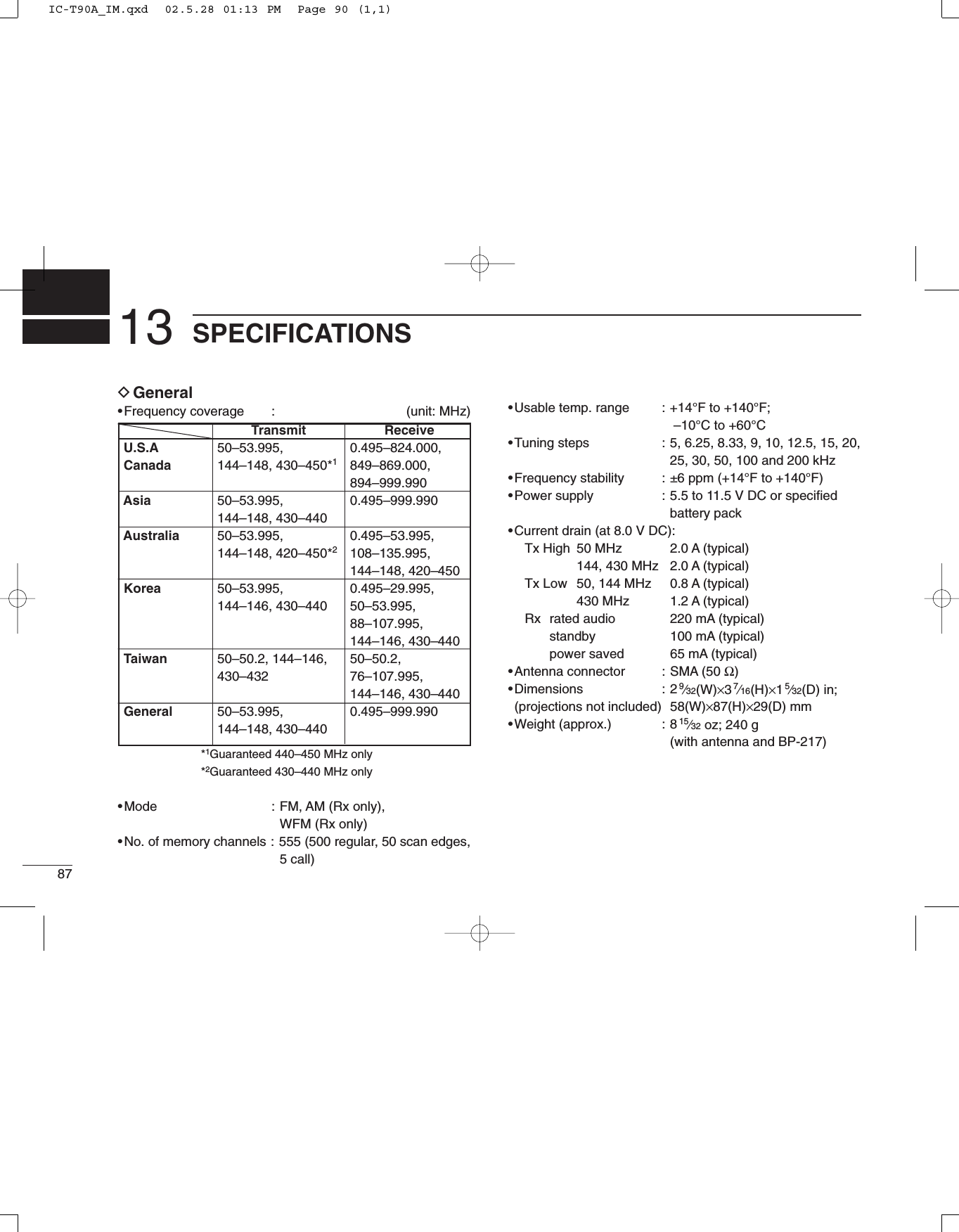
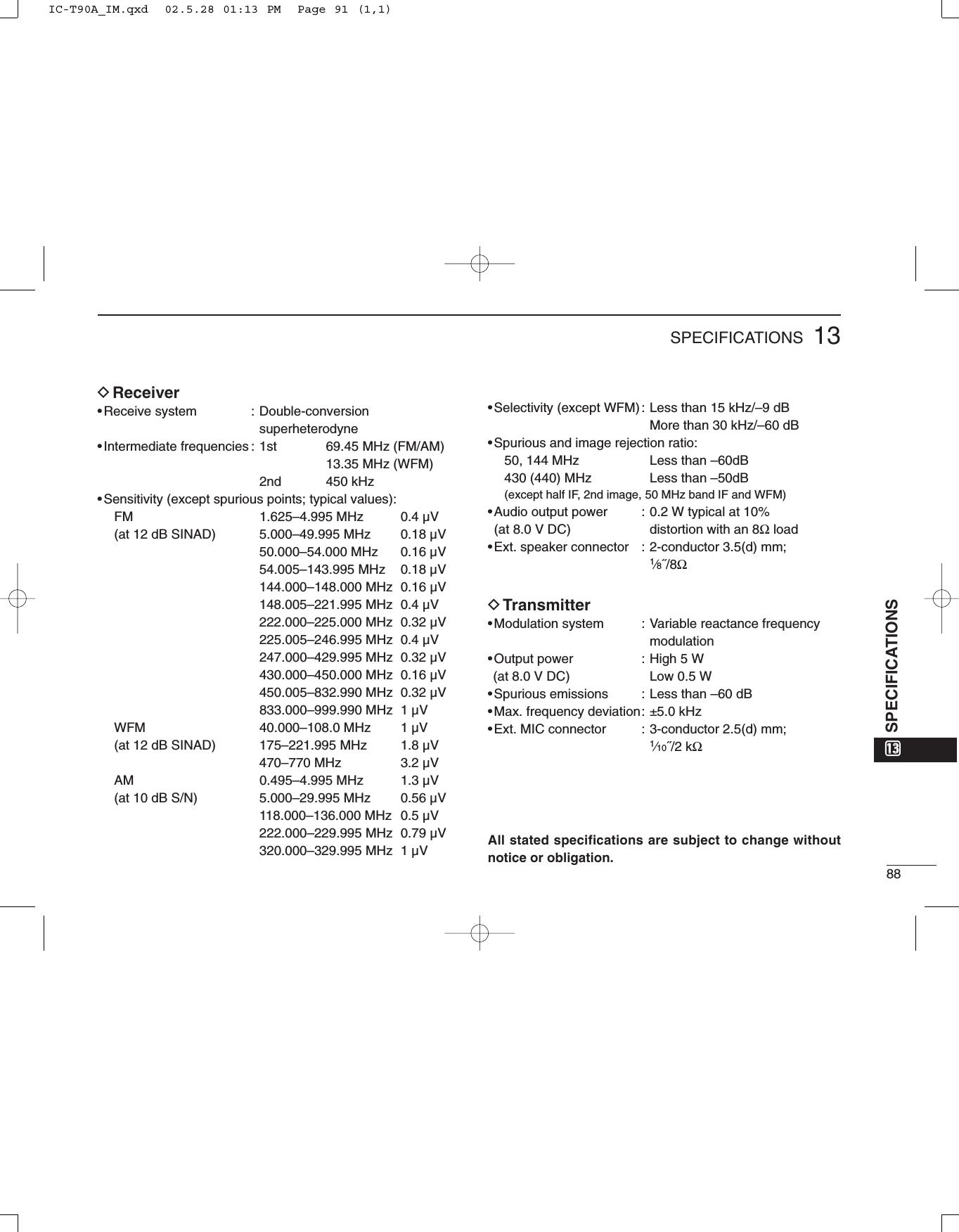
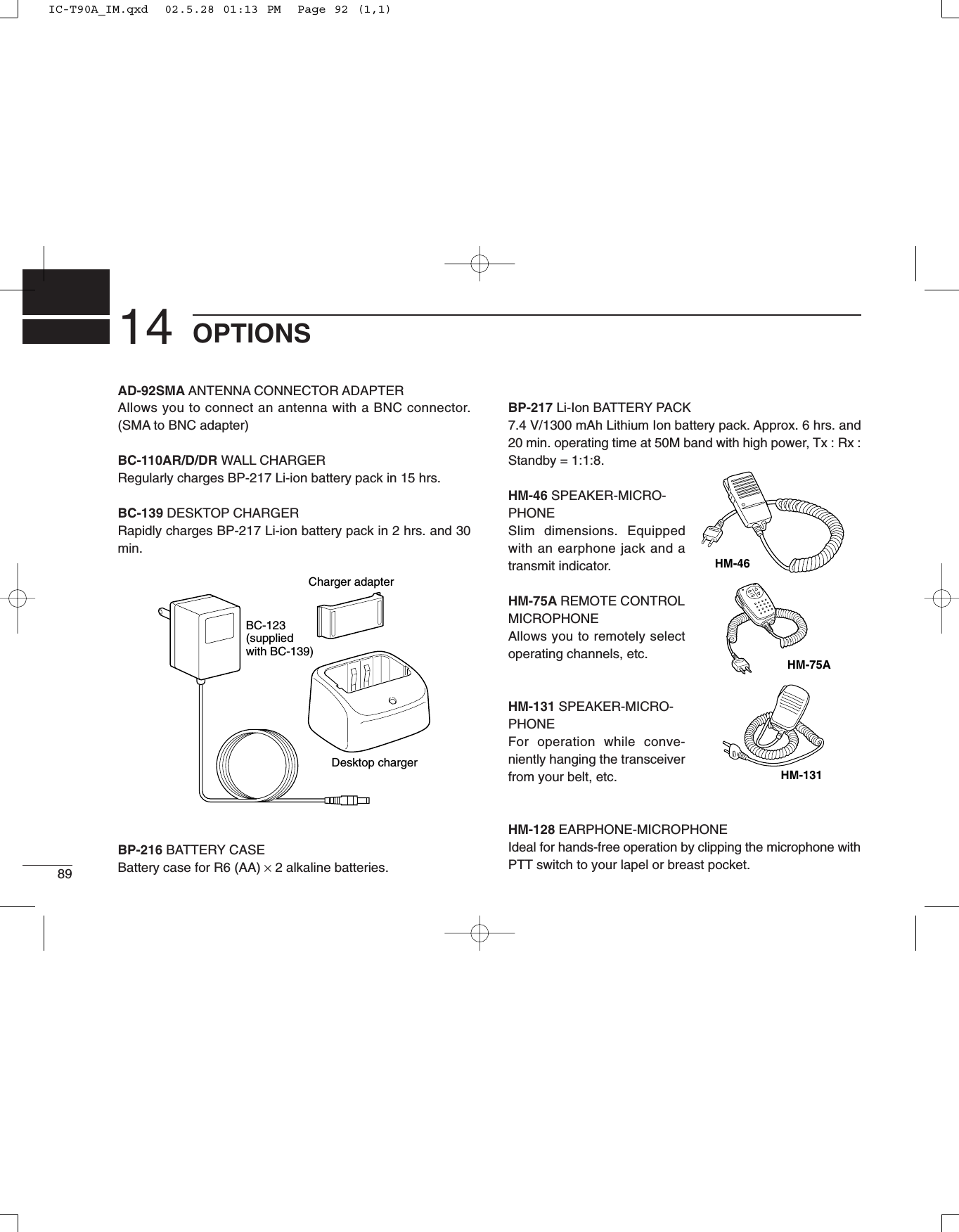
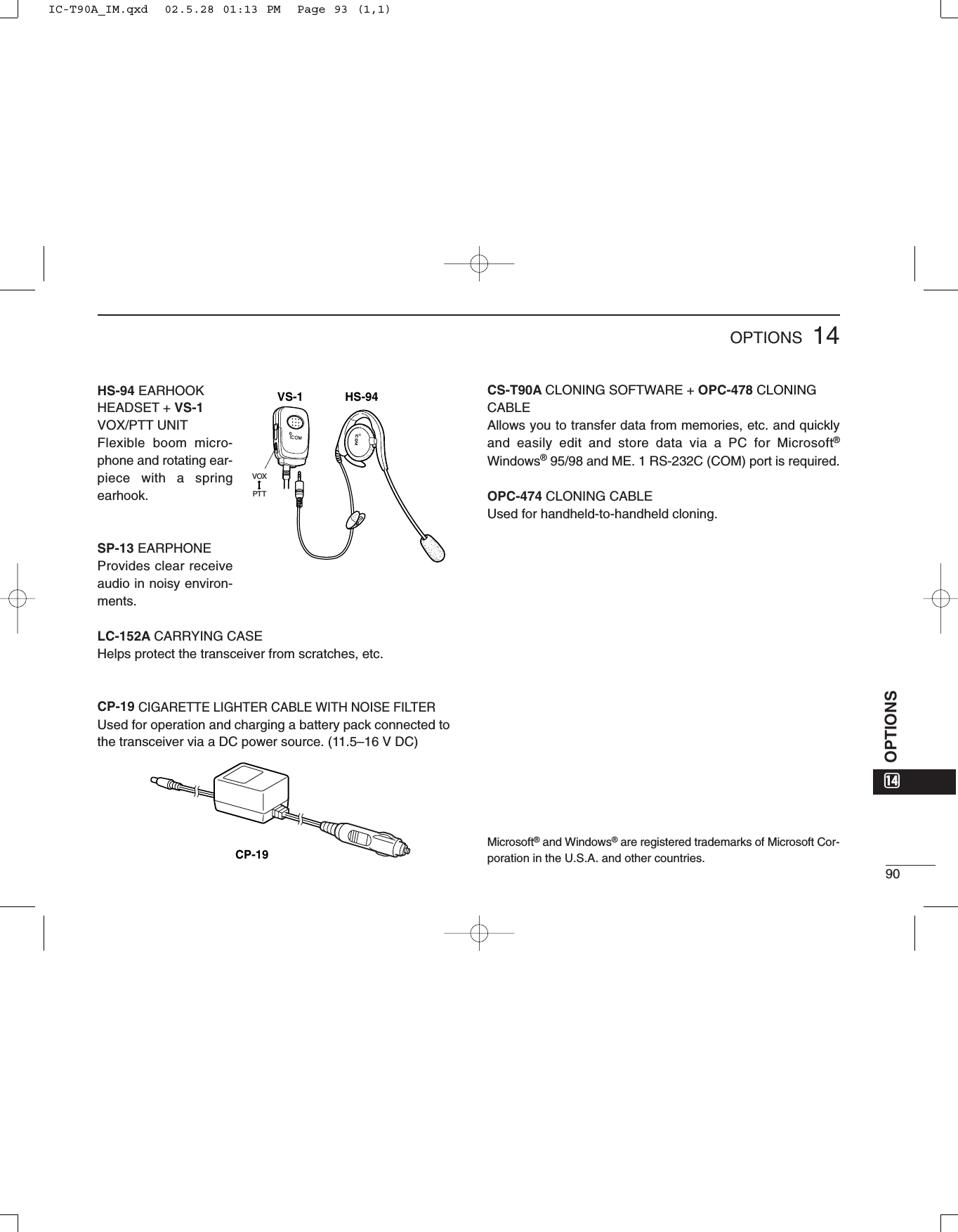

![■ TV channel mode selectionPush [CALL/TV] several times.■ TV channel selectionRotate [DIAL].■ TV channel skip settingq Select TV channel mode.w Rotate [DIAL] to select desired channel.e Push and hold [5 SKIP] for 1 sec.■ Cancelling skip settingq Select TV channel mode.w While pushing [BAND], rotate [DIAL] to select desired skip channel.e Push and hold [SKIP] for 1 sec.■ Exchange [DIAL] and [∫]/[√] assignmentPush and hold [1 V↔D] for 1 sec.■ Key lock functionPush and hold [CALL/TV] for 1 sec. to turn the lock function ON and OFF.■ SET mode operationq Push and hold [8 SET] for 1 sec.w Rotate [DIAL] to select SET mode item.e Push [8 SET] momentarily, then rotate [DIAL] to change the setting.r Push [8 SET] momentarily to return to the condition of step w.t Push [VFO] to exit the SET mode.■ CPU reset operation• ALL resetq Turn power OFF.w While pushing and holding [BAND], [VFO] and [MR], turn power ON.• Partial resetq Turn power OFF.w While pushing and holding [VFO], turn power ON.FM SKIPP1V D2TONEBANDD3H/LMODESCANVFOMHziC-t90a4DUP5SKIP6M.N0RITMRS.MW7T.SCAN8SET9TS.DTMF.MCALL/TVLOCKABCMULTIBAND TRANSCEIVERPOCKET GUIDEImportant operating instructions are summed up in this and the following pagefor your simple reference.By cutting along the line and folding on the dotted line, it will become a cardsized operating guide which can easily be carried in a card case or wallet,etc.q Cut w Fold e Complete<CUT HERE>POCKET GUIDEIC-T90A_IM.qxd 02.5.28 01:13 PM Page 95 (1,1)](https://usermanual.wiki/ICOM-orporated/IC-T90A/User-Guide-257988-Page-97.png)
![QUICK REFERENCE■ VFO/MEMORY MODE selectionVFO mode : Push [VFO].MEMORY mode : Push [MR].■ Changing frequency bandPush [BAND].■ Frequency settingq Select VFO mode.w Rotate [DIAL], or enter the desired frequency from the keypad.[e.g. 1] 445.600 MHz[4], [4], [5], [•], [6], [0], [0][e.g. 2] 0.684 MHz[0], [•], [6], [8], [4]■ Changing receiving modePush [MODE].■ Adjusting audio output levelPush [∫]/[√] (continuously changes while holding).■ Adjusting squelch levelWhile pushing [SQL] rotate [DIAL].■ MEMORY channel selectionq Select MEMORY mode.w Rotate [DIAL], or use keypad.■ MEMORY channel programming[e.g.] Program 445.600 MHz into MR CH 2q Select VFO mode.w Rotate [DIAL], or use keypad to set 445.600 MHz.e Push and hold [MR S.MW] for 1 sec. to indicate memory channels.r Rotate [DIAL] to select MR CH 2.t Push and hold [MR S.MW] for 1 sec. (VFO mode is selected after programming.)■ MEMORY channel clearingq Select the desired memory channel. w Push and hold [MR S.MW] for 1 sec.w Push [CALL/TV] several times to select “CLR”.e Push and hold [MR S.MW] for 1 sec. to clear the information.■ Scanning in VFO modeq Select VFO mode.w While pushing and holding [MODE SCAN], rotate [DIAL] to select scan edge from full (ALL), band (BAND) and program (PROG 0–24) scans.e Release [MODE SCAN] to start the scan.r Push [VFO] to stop the scan.■ Scanning in MEMORY modeq Select MEMORY mode.w For the memory bank scan, push [MR] to select memory bank mode and push [BAND] to select the de-sired memory bank.e While pushing and holding [MODE SCAN], rotate [DIAL] to select scan mode from memory (ALL) and bank (BANK) scans.r Release [MODE SCAN] to start the scan.t Push [VFO] to stop the scan.IC-T90A_IM.qxd 02.5.28 01:13 PM Page 96 (1,1)](https://usermanual.wiki/ICOM-orporated/IC-T90A/User-Guide-257988-Page-98.png)