ICOM orporated IC-T90A Amateur Transceiver with Scanning Receiver User Manual IC T90A IM
ICOM Incorporated Amateur Transceiver with Scanning Receiver IC T90A IM
Users Manual

This device complies with Part 15 of the FCC Rules. Operation is sub-
ject to the following two conditions: (1) This device may not cause
harmful interference, and (2) this device must accept any interference
received, including interference that may cause undesired operation.
iT90A
MULTIBAND FM TRANSCEIVER
INSTRUCTION MANUAL
WARNING: MODIFICATION OF THIS DEVICE TO RECEIVE CEL-
LULAR RADIO TELEPHONE SERVICE SIGNALS IS PROHIBITED
UNDER FCC RULES AND FEDERAL LAW.
IC-T90A_IM.qxd 02.5.28 01:12 PM Page a (1,1)

FOREWORD
i
Thank you for purchasing this Icom product. The IC-T90A
MULTIBAND TRANSCEIVER is designed and built with
Icom’s superior technology and craftsmanship. With proper
care, this product should provide you with years of trouble-
free operation.
The IC-T90A is a tri-band, 6 m, 2 m (140 MHz), 440 MHz FM
transceiver that offers a wide-band AM, FM and WFM scan-
ning receiver. Not only you can hear your favorite TV pro-
grams with the pre-programmed TV memories, but also you
can listen to short wave, AM and FM broadcast radio stations,
police, fire, military, aircraft, various amateur bands and more.
New DMS(Dynamic Memory Scan) bank scanning provides
555 alphanumeric memory channels, including 50 band
edges, with a maximum of 18 banks or 100 channels per
bank, you can pick and choose any desired channel for scan-
ning from the 500 memories.
The supplied BP-217
LITHIUM
-
ION BATTERY PACK
provides full
5 W outputs. Along with the energy conserving settings the
BP-217 provides up to 5 to 6 hours of operating time.
The supplied MB-83 swivel type belt clip performs quick draw
action for attach/detach the transceiver from the belt clip.
And newly designed antenna also provides a stable signal
strength.
We want to thank you for making your IC-T90A your radio of
choice, and hope
you agree with Icom’s philosophy of “technology first.” Many
hours of research and development went into the design of
your IC-T90A.
ïï
FEATURES
❍
Tri-band FM transceiver
❍
Wide-band receiver
—Covers 495 KHz to 999.990 MHz
❍
New DMS (Dynamic Memory Scan)
bank scan
❍
Lithium-Ion technology
❍
Rugged palm sized, weather-resis-
tant construction
❍
DTCS and CTCSS tone squelch
❍
Simple operation
IC-T90A_IM.qxd 02.5.28 01:12 PM Page b (1,1)
ii
IMPORTANT
READ ALL INSTRUCTIONS carefully and completely
before using the transceiver.
SAVE THIS INSTRUCTION MANUAL —This in-
struction manual contains important operating instructions for
the IC-T90A.
EXPLICIT DEFINITIONS
The explicit definitions below apply to this instruction manual.
WORD
WARNING
CAUTION
NOTE
DEFINITION
Personal injury, fire hazard or electric
shock may occur.
If disregarded, inconvenience only. No risk
of personal injury, fire or electric shock.
Equipment damage may occur.
Icom, Icom Inc. and the logo are registered trademarks of Icom
Incorporated (Japan) in the United States, the United Kingdom,
Germany, France, Spain, Russia and/or other countries.
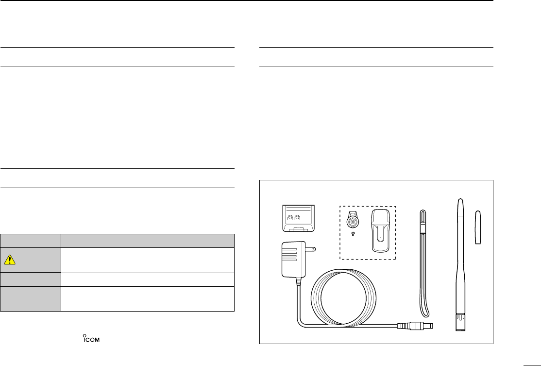
SUPPLIED ACCESSORIES
Accessories included with the transceiver: Qty.
qLi-Ion battery pack (BP-217) .......................................... 1
wWall charger* (BC-110AR/D/DR) .................................... 1
eMB-83 swivel belt clip .............................................. 1 set
rHandstrap........................................................................ 1
tAntenna (FA-S6270D; with 50M band adapter) ....... 1 set
* Not supplied with some versions.
q
w
ert
IC-T90A_IM.qxd 02.5.28 01:12 PM Page 1 (1,1)

iii
WARNING RF EXPOSURE! This device emits
Radio Frequency (RF) energy. Extreme caution should be
observed when operating this device. If you have any ques-
tions regarding RF exposure and safety standards please
refer to the Federal Communications Commission Office of
Engineering and Technology’s report on Evaluating
Compliance with FCC Guidelines for Human Radio frequency
Electromagnetic Fields (OET Bulletin 65)
WARNING! NEVER hold the transceiver so that the
antenna is very close to, or touching exposed parts of the
body, especially the face or eyes, while transmitting. The
transceiver will perform best if the microphone is 1 to 2 in (2
to 5 cm) away from the lips and the transceiver is vertical.
WARNING! NEVER operate the transceiver with a
headset or other audio accessories at high volume levels.
Hearing experts advise against continuous high volume oper-
ation. If you experience a ringing in your ears, reduce the vol-
ume level or discontinue use.
NEVER CONNECT a power supply more than
11.5 V DC to the DC jack. The supply voltage must be
between 5.5 V and 11.5 V to prevent damaging the trans-
ceiver.
NEVER connect the transceiver to an AC outlet . Such a
connection will damage the transceiver.
NEVER connect the transceiver to a power source that is
DC fused at more than 5 A. Accidental reverse connection will
be protected by this fuse, but higher fuse values will not give
proper protection against such accidents and the transceiver
will be ruined.
DO NOT operate the transceiver near unshielded electrical
blasting caps or in an explosive atmosphere.
AVOID using or placing the transceiver in direct sunlight or
in areas with temperatures below +14°F (–10°C) or above
+140°F (+60°C).
The use of non-Icom battery packs/chargers may impair
transceiver performance and invalidate the warranty.
Even when the transceiver power is OFF, a slight current still
flows in the circuits. Remove the battery pack or case from
the transceiver when not using it for a long time. Otherwise,
the battery pack or installed batteries will become exhausted.
For U.S.A. only
CAUTION: Changes or modifications to this device, not ex-
pressly approved by Icom Inc., could void your authority to
operate this device under FCC regulations.
CAUTIONS
IC-T90A_IM.qxd 02.5.28 01:12 PM Page 2 (1,1)

iv
FOREWORD ............................................. i
IMPORTANT ............................................. ii
EXPLICIT DEFINITIONS .......................... ii
SUPPLIED ACCESSORIES ..................... ii
CAUTIONS ............................................... iii
TABLE OF CONTENTS ........................... iv
qQUICK REFERENCE GUIDE ........ 1 – 6
wPANEL DESCRIPTION ................ 7– 12
■Panel description ............................. 7
■Function display ............................. 11
eBATTERY CHARGING .............. 13 – 16
■Battery attachment ......................... 13
■Battery cautions ............................. 13
■Regular charging ........................... 14
■Rapid charging ............................... 15
■Battery case ................................... 16
■External power operation ............... 16
rBASIC OPERATION .................. 17 – 34
■Turning power ON ......................... 17
■Tuning step .................................... 18
■Setting a frequency ........................ 19
■Mode selection ............................... 20
■Operating band and receive mode
selection ......................................... 21
■Setting squelch level ...................... 22
■Receiving ....................................... 23
■RIT function ................................... 27
■Attenuator function ......................... 27
■Transmitting ................................... 28
■Repeater operation ........................ 29
■Duplex operation ............................ 31
■Split operation ................................ 32
■Auto repeater function ................... 33
■1750 Hz tone ................................. 34
tMEMORY/CALL CHANNELS .... 35 – 44
■General .......................................... 35
■Calling up memory channels ......... 36
■Programming memory channels .... 37
■Transferring memory contents
to VFO ........................................... 38
■Copying memory contents ............. 39
■Memory names .............................. 39
■Memory bank ................................. 41
■Memory clear ................................. 43
■Call channel ................................... 44
ySCAN OPERATION ................... 45 – 49
■Scan types ..................................... 45
■VFO scan ....................................... 46
■Frequency skip function ................. 47
■Skip channel setting ....................... 47
■Memory scan ................................. 48
■Memory bank scan ........................ 48
■Scan notes ..................................... 49
uPRIORITY WATCH .................... 50 – 54
■Priority watch types ........................ 50
■Priority alert .................................... 50
■Priority watch operation ................. 51
iSET MODE ................................ 55 – 66
■Set mode ....................................... 55
■Set mode items ............................. 56
oOTHER FUNCTIONS ................ 67– 80
■Programming a DTMF code .......... 67
■Transmitting a DTMF code ............ 68
■Clearing a DTMF memory ............. 69
■Confirming a DTMF memory ......... 69
■Tone frequency and DTCS code .... 70
■Tone/DTCS squelch ....................... 71
■Pocket beep ................................... 71
■Available tone frequencies ............. 72
■Available DTCS code ..................... 72
■Tone scan ...................................... 73
■Beep tones ..................................... 74
■Dial speed acceleration ................. 74
■Lock function .................................. 74
■Morse code synthesizer ................. 75
■Power save .................................... 75
■Time-out timer ................................ 76
■PTT lock ......................................... 76
■Auto power OFF ............................ 76
■Auto power ON .............................. 76
■Weather channel operation ............ 77
■Cloning function ............................. 79
■[SP/MIC] jacks ............................... 79
■Resetting ........................................ 80
!0 HM-75A REMOTE CONTROL
MICROPHONE ................................. 81
!1 TROUBLESHOOTING ..................... 82
!2 TV FREQUENCY TABLE ........... 83 – 86
!3 SPECIFICATIONS ..................... 87 –88
!4 OPTIONS ................................... 89– 90
POCKET GUIDE
TABLE OF CONTENTS
qq
ww
ee
rr
tt
yy
uu
ii
oo
!!00
!!11
!!22
!!33
!!44
IC-T90A_IM.qxd 02.5.28 01:12 PM Page 3 (1,1)
1
QUICK REFERENCE GUIDE
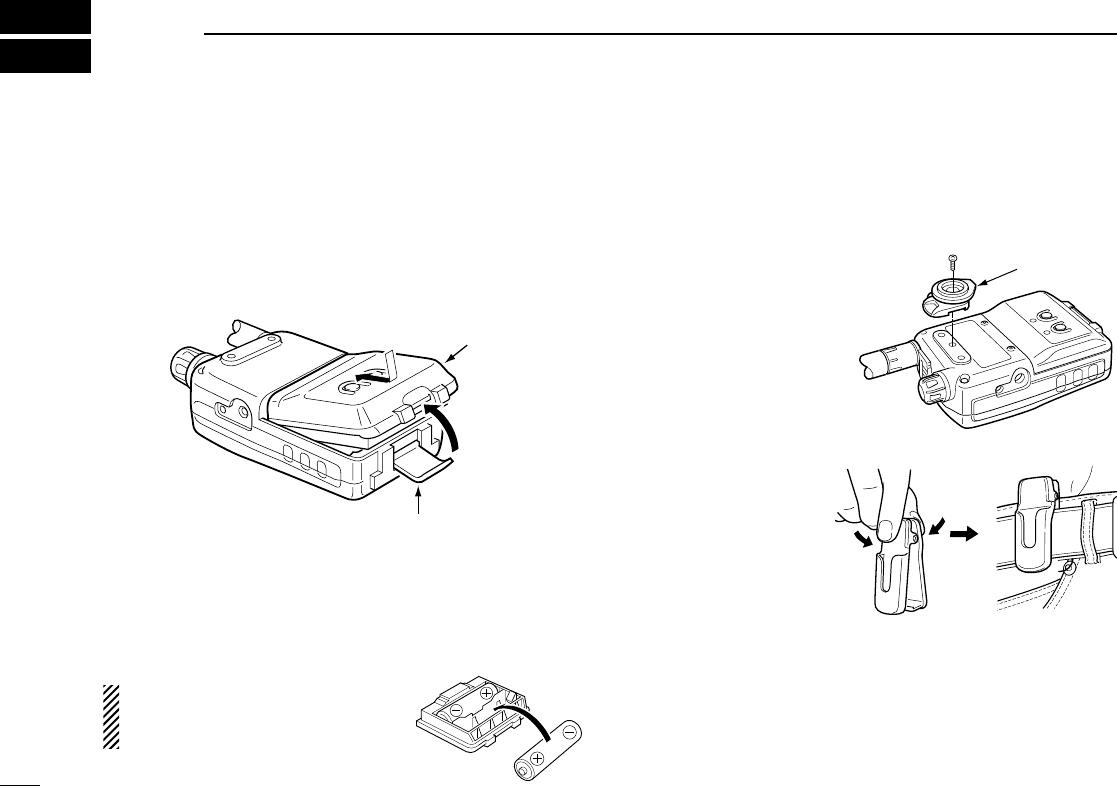
■Installing the battery pack
qOpen the latch. Then, attach the Li-Ion battery pack
(BP-217) or battery case (BP-216).
•Be sure to observe the correct direction.
•Charge Li-Ion battery pack before use.
wLock the latch.
NOTE: The battery pack is provided uncharged. BE SURE to
charge the battery before using it with the transceiver.
DInstalling the alkaline batteries
Install 2 R6 (AA) size alkaline batteries into BP-216.
•Be sure to observe the correct polarity.
Keep battery contacts clean. It’s a
good idea to clean battery terminals
once a week.
■Accessory attachment
DAttach the swivel belt clip
Supplied swivel belt clip is useful for easy detach/attach the
transceiver from/to the belt.
qAttach the stopper to
the transceiver with
the supplied screw.
wClip the belt clip to
your belt.
Battery pack or
battery case
Latch
q
w
stopper
supplied
screw
1
IC-T90A_IM.qxd 02.5.28 01:12 PM Page 4 (1,1)
2
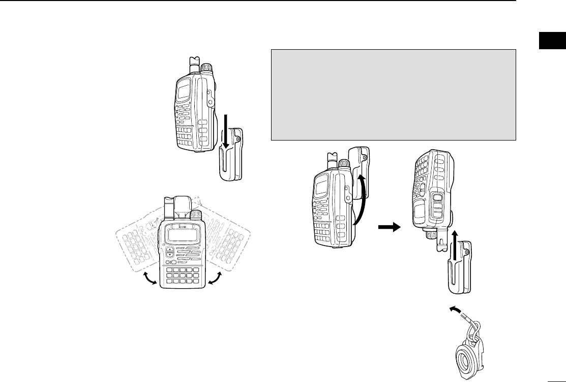
QUICK REFERENCE GUIDE
eInsert the transceiver to the end of the
clip as shown right.
•Once the transceiver
is locked in place, it
will swivel 360
degrees as shown
right.
To remove:
rTurn the transceiver upside down, and then lift to release
the transceiver from the belt clip as shown upper right.
DHandstrap
Slide the handstrap through the loop on
the top of the belt clip as shown right.
Facilitates carrying.
QUICK REFERENCE GUIDE
1
qq
iC-t
9
0
a
CAUTION!
HOLD THE TRANSCEIVER TIGHTLY, WHEN ATTACHING
OR REMOVING THE TRANSCEIVER TO/FROM THE
BELT CLIP.
If the transceiver accidentally dropped and the swivel belt
clip’s stopper is scratched, the swivel belt clip may not work
properly.
IC-T90A_IM.qxd 02.5.28 01:12 PM Page 5 (1,1)
3
1QUICK REFERENCE GUIDE
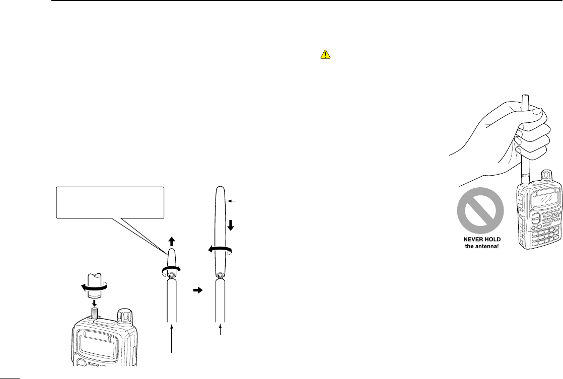
50M band
adapter
Attach the 50M band
adapter
Hold the base , then screw the
anttenna
for BC
band to 50M band,
through to 800M band
for WFM band
to
800M band
Detach the top cap*
*KEEP the the anttenna top cap
in the safe place during it not
in use.
DInstalling the antenna
Insert the supplied wide band antenna into the antenna con-
nector and screw down the antenna as shown below.
• 50M band adapter
Attach the 50M band antenna adapter before operating 50 M
band or receiving the signal below 50M band. Be sure to use
this 50M band adapter during the operation below 50M band.
You can operate the whole band with this adapter.
CAUTION!
TRANSMITTING WITHOUT ANTENNA MAY DAMAGE THE
TRANSCEIVER.
NEVER HOLD the anten-
na when carrying the trans-
ceiver or never brandish the
transceiver.
KEEP the jack covers at-
tached when the jack is not
in use, to avoid bad con-
tacts from dust and mois-
ture.
NOTE:
Commercially available antennas may increase transceiver
performance. An optional AD-92SMA ANTENNA CONNECTOR
ADAPTER is available to connect an external antenna with a
BNC connector.
IC-T90A_IM.qxd 02.5.28 01:12 PM Page 6 (1,1)
4
1
QUICK REFERENCE GUIDE
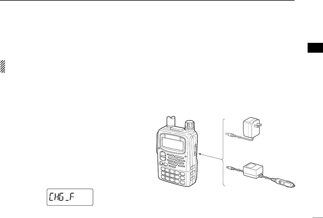
■Charging the Li-Ion battery pack
DCharging with the wall charger
qPush and hold [PWR] to turn the transceiver power OFF.
wInsert the charger plug into the DC power jack of the trans-
ceiver.
ePlug the charger into AC wall outlet.
rCharging starts and battery indicator “” on the display
blinks.
tIt takes approximately 15 hours to charge an empty BP-
217 Li-Ion battery pack.
yUnplug the charger from the AC wall outlet when charging
is completed.
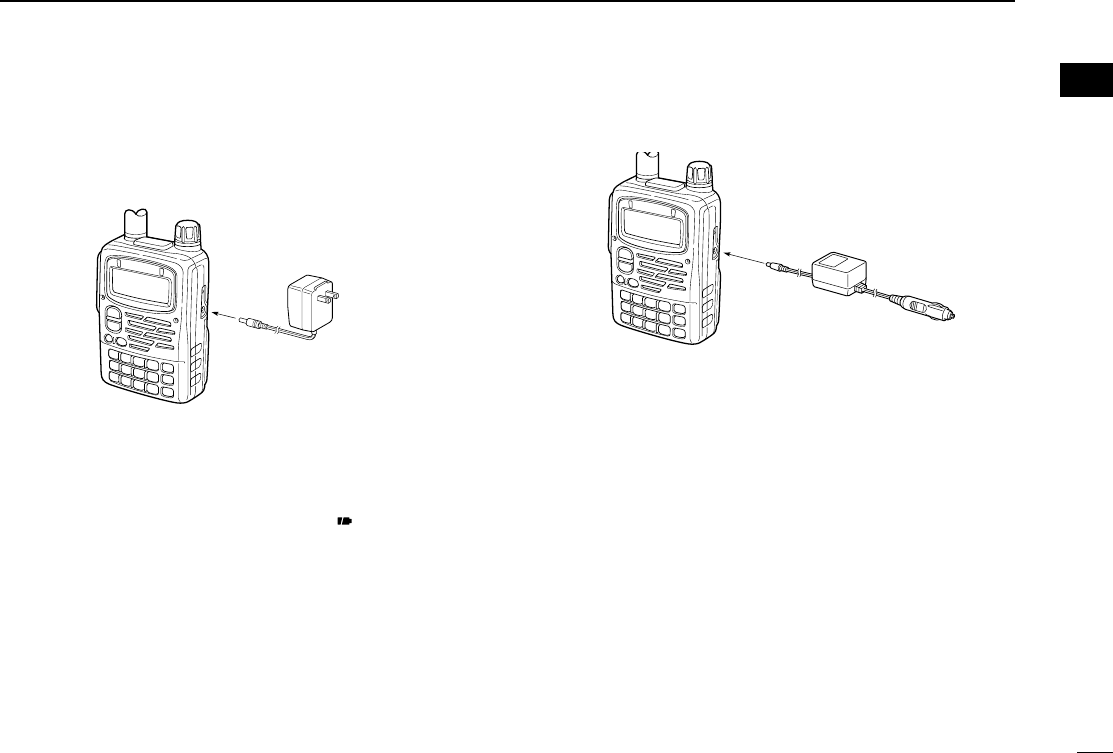
DCharging with the CP-19 Cigarette Lighter
cable (optional)
qInsert the cigarette lighter adapter cable into the DC power
jack of the transceiver.
wConnect the CP-19 cigarette lighter adapter cable to the
cigarette lighter socket.
eCharging starts and battery indicator on the display flash.
NOTE:
•The BP-217 can be charged in background during you operate the
transceiver. (p. 5).
•Charging will be suspended during transmitting.
•“CHG_F” appears when the charging is completed with the power
turned OFF.
•NEVER connect the cigarette lighter socket or external regulated
DC power supply directly to the transceiver. Such a connection will
damage the transceiver.
•Remove CP-19 from the transceiver when not using it. Otherwise,
the vehicle battery will become exhausted.
IC-T90A with BP-217
BC-110AR/D/DR
to
DC power jack
to AC outlet
CP-19
(optional)
to
DC power
jack
to a 12 V
cigarette lighter
socket
QUICK REFERENCE GUIDE
qq
IC-T90A_IM.qxd 02.5.28 01:12 PM Page 7 (1,1)
5
1QUICK REFERENCE GUIDE
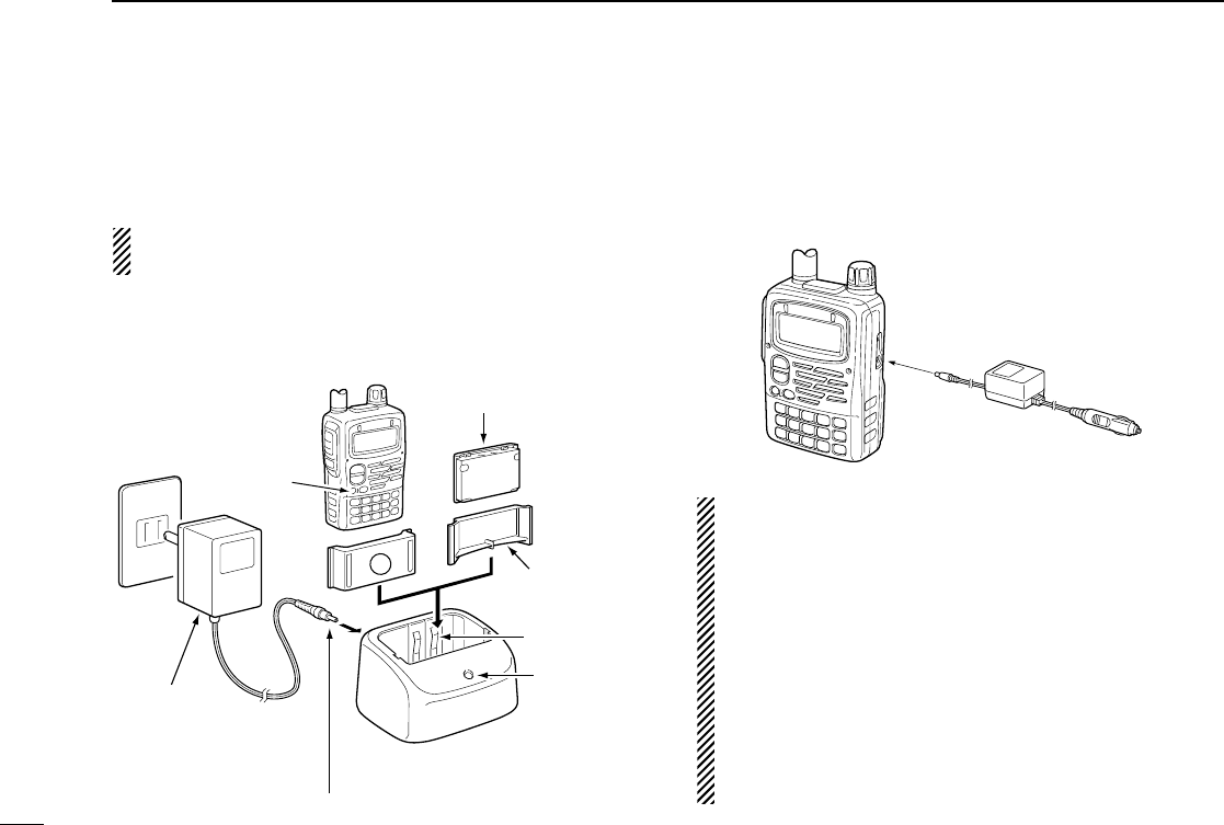
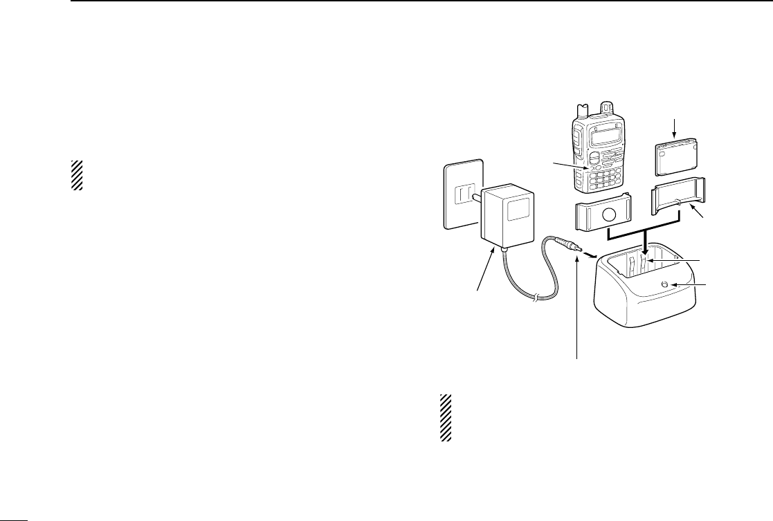
■Rapid charging
The optional BC-139 provides rapid charging of the battery
pack.
CAUTION: To avoid damage to the transceiver, turn trans-
ceiver OFF while charging.
•Charging period: 2.5 hours (w/BP-217)
■External power operation
An optional CP-19 cigarette lighter cable can be used for ex-
ternal power operation from a 12 V DC cigarette lighter
socket.
•Power supply range is between 5.5–11.5 V DC.
NEVER CONNECT OVER 11.5 V DC direct into the
DC power jack of the transceiver.
•BE SURE to use the CP-19 when connecting a regulated
12 V DC power supply.
•If a battery pack is attached, the voltage of the external
power supply must be within 11.5–16 V DC, otherwise,
the battery power may be used for operation.
•The maximum output power is 5.0 W regardless of the
power supply voltage.
•Remove the cables from the transceiver when not using
it. Otherwise, the vehicle battery will become exhausted.
CP-19
(optional)
to
DC power
jack
to a 12 V
cigarette lighter
socket
Turn power
OFF.
Check the
orientation.
BP-217
Li-Ion battery pack
to AC
outlet
BC-139 (optional)
desktop charger
BC-123
(supplied with
BC-139)
to [AC ADAPTER] jack
A
Adapter (supplied
with BC-139)
LED
Charging:
Orange
Finished:
Green
Charging
terminal
IC-T90A_IM.qxd 02.5.28 01:12 PM Page 8 (1,1)
6
1
QUICK REFERENCE GUIDE
■Your first contact
Now that you have your IC-T90A ready to operation, you are
probably excited to get on the air. We would like to take you
through a few basic operation steps to make your first “On
The Air” an enjoyable experience.
DFirst contact
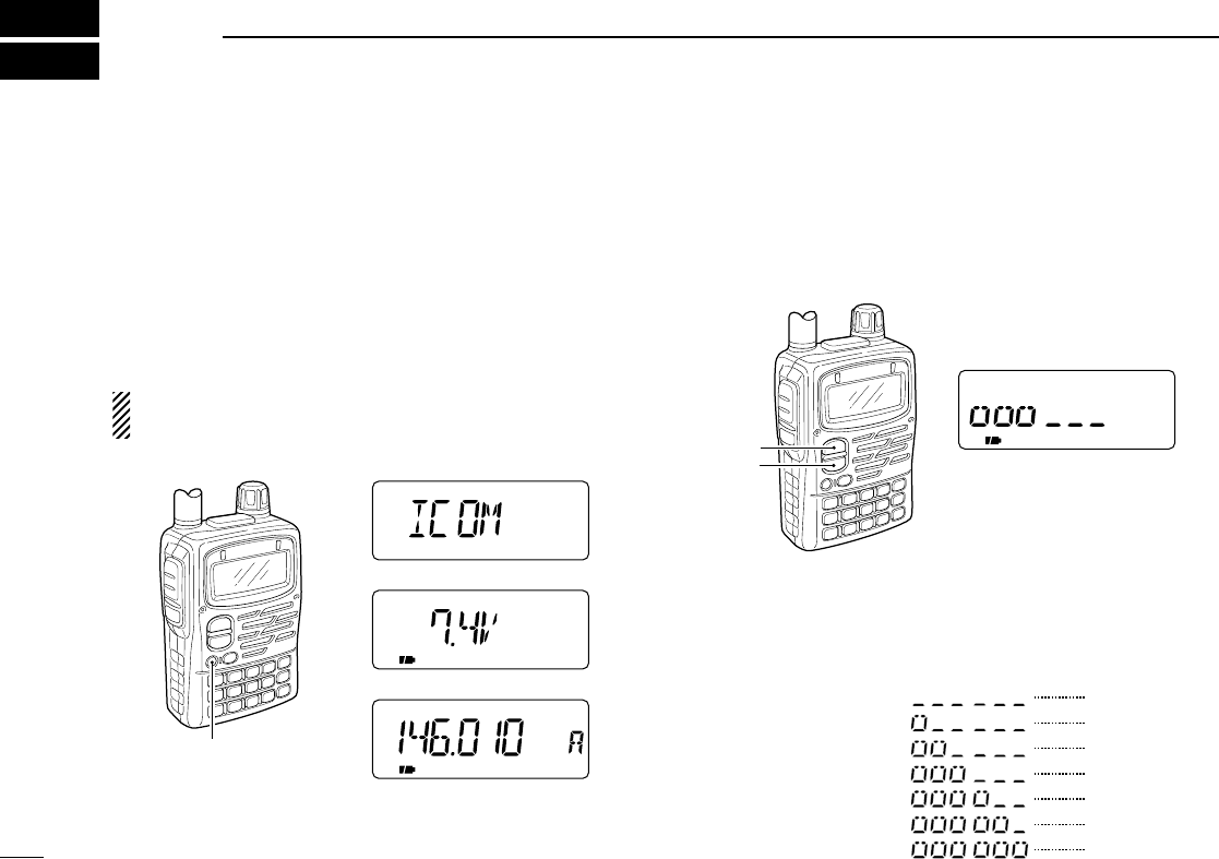
qPush and hold [PWR] for 1 sec. to turn the transceiver
power ON.
•The function display shows “ICOM,” current voltage then the op-
erating frequency.
wPush [BAND] several times until desired operating band
(VHF; 51.000, 146.010 or UHF; 440.000 as default)
appears on the display.
ePush [Y](or [Z]) several times to adjust desired audio
level.
rRotate [DIAL] to select receive frequency.
‘Direct frequency input’via the keypad also available.
(p. 19)
tHold the transceiver approximately 2 in. (5 cm) from your
mouth.
yPush and hold [PTT], then speak in your normal voice
level.
uRelease [PTT] switch to receive.
•Repeat steps, t, yand uto continue communication.
r
e
q
w
yu
[DIAL]
[PTT]
[UP/DOWN]
[BAND]
[PWR]
[Mic]
QUICK REFERENCE GUIDE
FM DUP SKIPTP
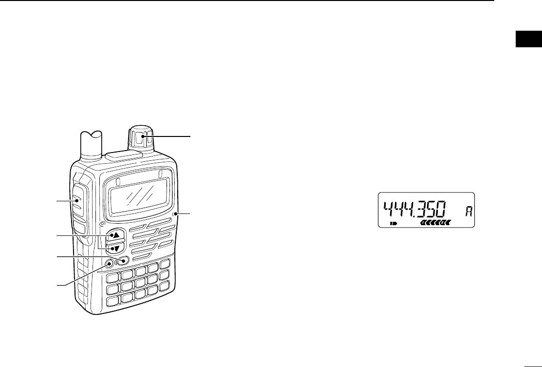
[EXAMPLE] Setting the
receive frequency to
444.350 MHz
qq
IC-T90A_IM.qxd 02.5.28 01:12 PM Page 9 (1,1)
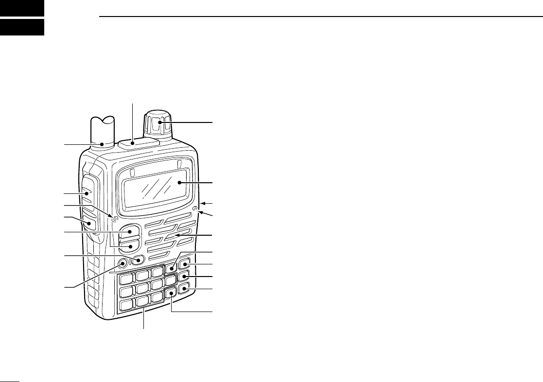
■Panel description qPOWER SWITCH [PWR]
Push for 1 sec. to turn the transceiver power ON and OFF.
wBAND SWITCH [BAND]
➥Push to select the operating band (5MHz, Air, VHF, UHF,
etc.). (p. 21)
➥Push to select the memory bank or push to proceed the
memory name cursor while programming the memory
option. (pgs. 39, 41)
➥Push for 1 sec. to have Morse code synthesizer. (p. 75)
➥While pushing [PTT], this key sends a DTMF “D.”
eUP/DOWN SWITCHES [Y]/[Z]
➥Push to adjust the audio level by default. (p. 17)
➥Push to adjust the frequency when [Y]/[Z] and [DIAL]
are exchanged by pushing [1 V↔D] for 1 sec. (p. 23)
rMONITOR SWITCH [SQL] (p. 22)
➥Push and hold to temporarily open the squelch and
monitor the operating frequency.
➥While pushing, rotate the tuning dial to set the squelch
threshold level.
tTRANSMIT/RECEIVE INDICATOR
➥Lights green while receiving a signal or when the
squelch is open; lights red while transmitting.
➥Flashes green for 5 sec. when the scan stop LED func-
tion is in use and a scan is stopped. (pgs. 46, 62)
t
u
i
o
!0
!1
!2
!3
!4
Keypad !6–@5
!5
e
r
q
w
y
Function display
Speaker
Microphone
7
2PANEL DESCRIPTION
IC-T90A_IM.qxd 02.5.28 01:12 PM Page 10 (1,1)

8
2
PANEL DESCRIPTION
yPTT SWITCH [PTT]
➥Push and hold to transmit in 50/144/430 MHz amateur
bands; release to receive. (p. 28)
•When WFM or AM mode is selected, transmission is impossi-
ble.
uANTENNA CONNECTOR (p. 3)
Connects the supplied antenna.
iEXTERNAL SPEAKER AND MICROPHONE JACKS
[SP/MIC]
Connects an optional speaker-microphone or headset, if
desired. The internal microphone and speaker will not
function when any external equipment is connected. (See
pgs. 89, 90 for a list of available options.)
oTUNING DIAL [DIAL]
➥Rotate [DIAL] to set operating frequencies, memory
channels, set mode contents, etc. (pgs. 19, 36, 55)
➥While pushing [SQL], sets the squelch level. (p. 22)
➥While pushing [BAND], sets the operating band in VFO
mode. (p. 21)
➥While pushing [Y]/[Z], adjusts the audio level (when
[Y]/[Z] and [DIAL] are not exchanged). (p. 17)
!0 EXTERNAL DC POWER JACK [DC 11.0 V]
➥Allows charging of the BP-217 using the BC-110A/D wall
charger, or using an optional CP-19 cigarette lighter
cable.
➥To connect regulated power supply with optional CP-19
cigarette lighter cable.
!1 MODE/SCAN SWITCH [MODE SCAN]
➥Push to select the operating mode (FM, WFM,
AM). (p. 21)
➥Push for 1 sec. to start a scan. (p. 45)
➥While pushing [PTT], this key sends a DTMF “#” (F).
!2 VFO SWITCH [VFO MHz]
➥Selects and toggles between VFO A and B.
(p. 20)
➥Selects and toggles between the 1 MHz or 10
MHz tuning steps when pushed for 1 sec.
(p. 18)
➥Returns to previous operating condition while setting fre-
quency or memory channel, or while in set mode.
➥While pushing [PTT], this key sends a DTMF code “A”.
!3 MEMORY SWITCH [MR S.MW]
➥Selects and toggles between memory mode
and memory bank. (p. 20)
➥Push for 1 sec. to enter memory write condi-
tion. (p. 37)
➥Push for 2 sec. to write the operating frequency into the
selected memory channel in VFO mode.
•Keep pushing for 2 sec. or more to automatically select the
next memory channel, if desired. (p. 38)
➥Push [MR S.MW] for 2 sec. to transfer the displayed fre-
quency into the VFO in memory mode. (p. 38)
MR
S.MW
B
VFO
MHz
A
MODE
SCAN
ww
PANEL DESCRIPTION
IC-T90A_IM.qxd 02.5.28 01:12 PM Page 11 (1,1)

9
2PANEL DESCRIPTION
➥While pushing [PTT], this key sends a DTMF “B”.
!4 CALL/LOCK SWITCH [CALL/TV LOCK]
➥Toggles between call channel, TV channel,
weather channel (U.S.A. version only) and
VFO mode in sequence. (p. 20)
➥Push for 1 sec. to toggle the lock function ON and OFF.
(p. 74)
•“
é
” appears while the key lock function is in use.
➥While pushing [PTT], this key sends a DTMF code “C”.
!5 DTMF MEMORY SWITCH [• DTMF.M]
➥Push for 1 sec. to enter the DTMF memory
channel. (p. 67)
➥Inputs MHz digit for frequency input. (p. 19)
➥While pushing [PTT], this key sends a DTMF cod “M(E)”.
!6 VOLUME/DIAL SWITCH [1 V↔D]
➥Push for 1 sec. to exchange [Y]/[Z] and
[DIAL] functions. (p. 23)
•“VOL” appears when the tuning dial functions as a
volume control.
➥Inputs digit ‘1’for frequency input, memory channel se-
lection, etc.
➥While pushing [PTT], this key sends a DTMF code “1”.
!7 TONE SWITCH [2 TONE] (p. 70)
➥Push for 1 sec. to activate the following tone
functions in order.
•Subaudible tone encoder — “T” appears. (p. 29)
•Tone squelch — “T SQL” appears. (p. 71)
•Pocket beep — “T SQLS” appears. (p. 71)
•DTCS squelch — “DTCS” appears. (p. 71)
•DTCS beep — “SDTCS” appears. (p. 71)
•No tone operation — no tone indicator appears.
➥Inputs digit ‘2’for frequency input, memory channel se-
lection, etc.
➥While pushing [PTT], this key sends a DTMF code “2”.
!8 OUTPUT POWER SWITCH [3 H/L] (p. 28)
➥Push for 1 sec. to toggle output power be-
tween high and low.
•“LOW” appears when low output power is selected.
➥Inputs digit ‘3’for frequency input, memory channel se-
lection, etc.
➥While pushing [PTT], this key sends a DTMF code “3”.
!9 DUPLEX SWITCH [4 DUP] (pgs. 29, 31)
➥Push for 1 sec. to activate the following duplex
functions in order.
•Minus duplex operation — “–DUP” appears.
•Plus duplex operation — “DUP” appears.
•Simplex operation — no duplex indicator appears.
➥Inputs digit ‘4’for frequency input, memory channel se-
lection, etc.
➥While pushing [PTT], this key sends a DTMF code “4”.
4
DUP
3
H/L
2
TONE
1
V D
.
DTMF.M
CALL/TV
LOCK
C
IC-T90A_IM.qxd 02.5.28 01:12 PM Page 12 (1,1)

10
2
PANEL DESCRIPTION
@0 FREQUENCY SKIP SWITCH [5 SKIP]
➥Push for 1 sec. to turn the frequency skip func-
tion ON and OFF in VFO mode. (p. 47)
•“P SKIP” appears when the frequency skip function
is in use.
➥Push for 1 sec. to set the memory channel as the fol-
lowing skip channel in memory mode in order. (p. 48)
•Skip channel — “SKIP” appears.
•Frequency skip channel — “P SKIP” appears.
•Non-skip channel — no skip indicator appears.
➥Push for 1 sec. to program the pausing frequency as a
skip frequency while scanning. (p. 48)
➥Inputs digit ‘5’for frequency input, memory channel se-
lection, etc.
➥While pushing [PTT], this key sends a DTMF code “5”.
@1 MEMORY NAME SWITCH [6 M.N]
➥Push for 1 sec. to turn the memory name indi-
cation ON and OFF. (p. 39)
•Frequency appears for nameless memory chan-
nels.
➥Inputs digit ‘6’for frequency input, memory channel se-
lection, etc.
➥While pushing [PTT], this key sends a DTMF code “6”.
@2 TONE SCAN SWITCH [7 T.SCAN]
➥Push for 1 sec. to start a tone scan. (p. 73)
➥Inputs digit ‘7’for frequency input, memory
channel selection, etc.
➥While pushing [PTT], this key sends a DTMF code “7”.
@3 SET MODE SWITCH [8 SET]
➥Push for 1 sec. to enter the set mode. Push to
select the displayed set mode item after se-
lecting with [DIAL] while in the set mode.
(p. 55)
➥Inputs digit ‘8’for frequency input, memory channel se-
lection, etc.
➥While pushing [PTT], this key sends a DTMF code “8”.
@4 TUNING STEP SWITCH [9 TS]
➥Push for 1 sec. to select the tuning step.
(p. 18)
➥Inputs digit ‘9’for frequency input, memory
channel selection, etc.
➥While pushing [PTT], this key sends a DTMF code “9”.
@5 RIT/ATTENUATOR SWITCH [0 RIT]
➥Push for 1 sec. to enter the RIT/attenuator set
mode. Push to select the item after selecting
with [DIAL]. (p. 27)
•RIT function is available for 630.000 MHz and above.
•Attenuator for 629.995 MHz or less.
➥Inputs digit ‘0’for frequency input, memory channel se-
lection, etc.
➥While pushing [PTT], this key sends a DTMF code “0”.
0
RIT
9
TS
8
SET
7
T.SCAN
6
M.N
5
SKIP
ww
PANEL DESCRIPTION
IC-T90A_IM.qxd 02.5.28 01:13 PM Page 13 (1,1)
11
2PANEL DESCRIPTION
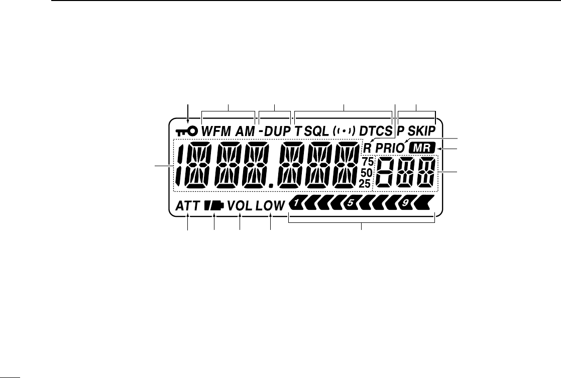
■Function display
qFREQUENCY READOUT
Shows the operating frequency, set mode contents, etc.
•The smaller “75,” “50” and “25” to the right of the readout indi-
cate 0.75, 0.5 and 0.25 kHz, respectively.
•The decimal point of the frequency flashes during scan.
wLOCK INDICATOR (p. 74)
Indicates that the lock function is in use.
eRECEIVE MODE INDICATORS (p. 21)
Show the receive mode.
•AM, FM and WFM are available.
rDUPLEX INDICATORS (pgs. 29, 31)
Appear when semi-duplex operation (repeater operation)
is in use.
•“–DUP” appears when minus duplex is selected; “DUP” only, ap-
pears when plus duplex is selected.
q
we r t yu
i
o
!0
!1!2!5 !3!4
IC-T90A_IM.qxd 02.5.28 01:13 PM Page 14 (1,1)

12
2
PANEL DESCRIPTION
tTONE INDICATORS (p. 70)
➥Appear when the following tone functions are activated.
•Subaudible tone encoder — “T” appears. (p. 29)
•Tone squelch — “T SQL” appears. (p. 71)
•Pocket beep — “T SQLS” appears. (p. 71)
•DTCS squelch — “DTCS” appears. (p. 71)
•DTCS beep — “SDTCS” appears. (p. 71)
➥“S” flashes when the correct tone or code is received
during pocket/DTCS beep operation. (p. 71)
yRIT INDICATOR (p. 27)
Appears when the RIT (Receive Incremental Tuning) func-
tion for 630.000 MHz and above is in use.
uSKIP SCAN INDICATOR (p. 48)
➥“SKIP” appears when a selected memory channel is set
as a skip channel.
➥“P SKIP” appears when the memory channel frequency
is set as a skip frequency in memory mode.
➥“P SKIP” appears when the frequency skip function is
turned ON in VFO mode.
iPRIORITY WATCH INDICATOR (p. 50)
Appears when priority watch is in use.
oMEMORY MODE INDICATOR (p. 21)
Appears when a memory channel is selected.
!0 MEMORY CHANNEL NUMBER READOUT (p. 20)
Shows the memory or call channel number, etc.
!1 S/RF INDICATORS (p. 28)
Shows the relative signal strength while receiving. Shows
the relative output power while transmitting.
!2 LOW POWER INDICATOR (p. 28)
Appears when low output power is selected.
!3 VOLUME EXCHANGE INDICATOR (p. 23)
Appears when the functions of tuning dial and [Y]/[Z]
switches are exchanged.
!4 BATTERY INDICATORS
➥Both segments appear when the batteries have ample
capacity.
•They do not appear when operating with an external power
source.
➥Only the right segment “” appears when the batteries
are nearing exhaustion.
➥Flash while charging the attached Li-Ion battery pack.
!5 ATTENUATOR INDICATOR (p. 27)
Appears when attenuator is in use.
ww
PANEL DESCRIPTION
IC-T90A_IM.qxd 02.5.28 01:13 PM Page 15 (1,1)

■Battery attachment
qAttach the Li-Ion battery pack (BP-217) or battery case
(BP-216).
•Be sure to observe the correct direction.
•Charge Li-Ion battery pack before use.
wLock the latch.
DOperating periods
The operating periods with BP-217 are:
50 MHz Approx. 6 hr.
144 MHz Approx. 5 hr.
440 MHz Approx. 5 hr.
at high power, Tx : Rx : Standby = 1:1:8
■Battery cautions
NEVER incinerate used battery packs. Internal battery gas
may cause an explosion.
NEVER immerse the battery pack in water. If the battery pack
becomes wet, be sure to wipe it dry BEFORE attaching it to
the transceiver.
NEVER short terminals of the battery pack. Also, current may
flow into nearby metal objects so be careful when placing bat-
tery packs in handbags, etc.
If your battery pack seems to have no capacity even after
being charged, completely discharge it by leaving the power
ON overnight. Then, fully charge the battery pack again. If the
battery pack still does not retain a charge (or very little), a
new battery pack must be purchased.
Use Icom battery packs, chargers and cables only. The use of
non-Icom products may impair transceiver performance and
invalidate the warranty.
Even when the transceiver power OFF, a slight current still
flows in the circuits. Remove the battery pack or case from
the transceiver when not using it for a long time. Otherwise,
the battery pack or installed batteries will become exhausted.
Battery pack or
battery case
Latch
q
w
3BATTERY CHARGING
13
IC-T90A_IM.qxd 02.5.28 01:13 PM Page 16 (1,1)
14
3
BATTERY CHARGING
■Regular charging
Prior to using the transceiver for the first time, the battery
pack must be fully charged for optimum life and operation.
CAUTION: To avoid damage to the transceiver, turn trans-
ceiver OFF while charging.
•Recommended temperature range for charging:
+32°F to +95°F; 0°C to +35°C
•Use the wall charger* (BC-110AR/D/DR) only. NEVER use
another manufactures’charger.
* Not supplied with some versions.
•An optional cable CP-19 (for 12 V cigarette lighter socket)
can be used instead of the AC adapters of the above charg-
ers.
DBattery indicators
The battery indicators flash while charging with no relation of
the power condition.
“CHG_F” appears when the charging is completed. Discon-
nect the wall charger in this case.
qAttach the battery pack to the transceiver.
wBe sure to turn the transceiver power OFF.
eConnect the AC adapter* (BC-110AR/D/DR) as shown
below.
* Not supplied with some versions.
rRemove any cables from the [DC11V] jack.
•Charging period: 15 hours (w/BP-217)
ee
BATTERY CHARGING
IC-T90A with BP-217 BC-110AR/D/DR
to AC outlet
CP-19
(optional)
to
DC power
jack
to a 12 V
cigarette lighter
socket
IC-T90A_IM.qxd 02.5.28 01:13 PM Page 17 (1,1)
15
3BATTERY CHARGING
■Rapid charging
The optional BC-139 provides rapid charging of the battery
pack.
•Charging period: 2.5 hours (w/BP-217)
CAUTION: To avoid damage to the transceiver, turn it OFF
while charging.
•Recommended temperature range for charging:
0°C to +35°C; +32°F to +95°F
•NEVER connect 2 chargers to the [AC ADAPTER] and
[DC11V] jacks.
•Use the supplied BC-123 for the BC-139 desktop charger.
Connect BC-123 to the [AC ADAPTER] jack.
•NEVER use another manufactures’charger.
•An optional cable CP-19 (for 12 V cigarette lighter socket)
can be used instead of the supplied AC adapter. Connect
one of these to the [DC11V] jack in this case.
If the charge indicator flashes orange, there may be a
problem with the battery pack (or charger). Re-insert the
battery pack or contact your dealer.
Turn power
OFF.
Check the
orientation.
BP-217
Li-Ion battery pack
to AC
outlet
BC-139 (optional)
desktop charger
BC-123
(supplied with
BC-139)
to [AC ADAPTER] jack
A
Adapter (supplied
with BC-139)
LED
Charging:
Orange
Finished:
Green
Charging
terminal
IC-T90A_IM.qxd 02.5.28 01:13 PM Page 18 (1,1)
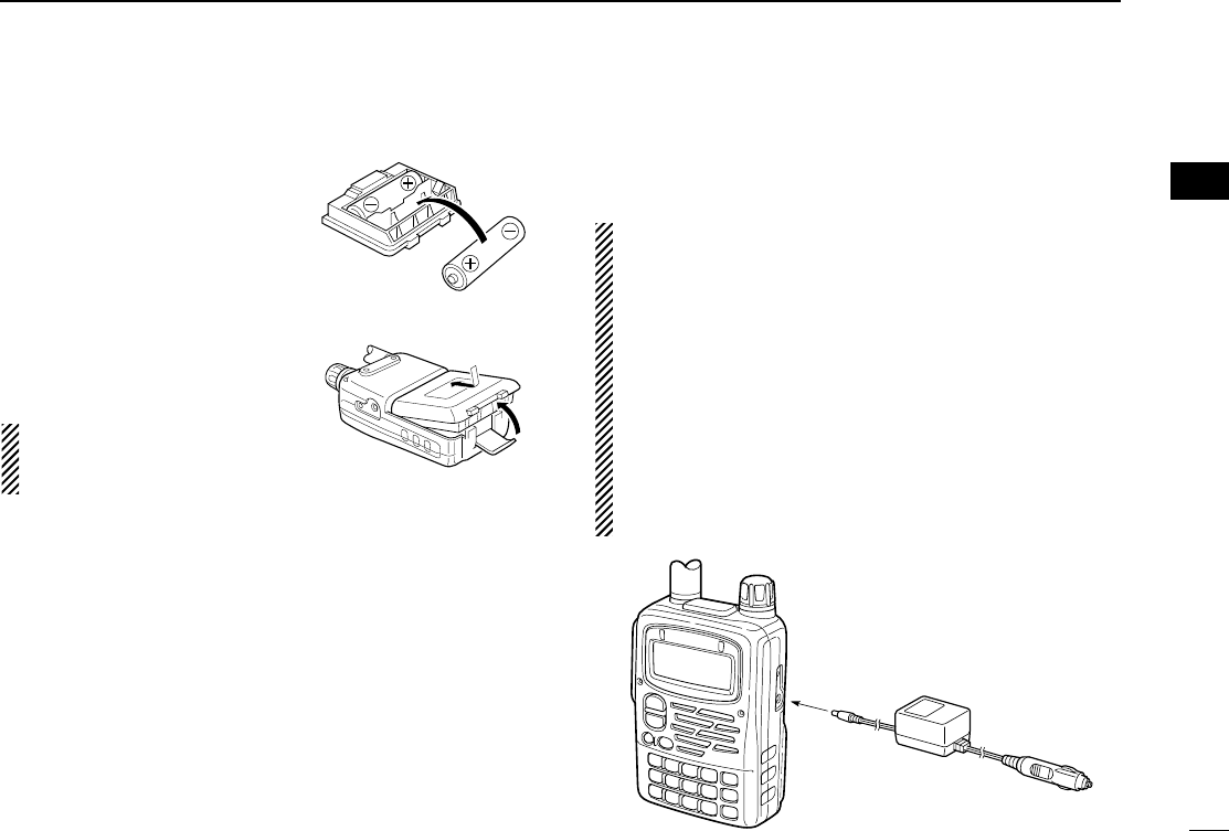
■Battery case
qInstall 2 R6 (AA) size alkaline
batteries into BP-216.
•Be sure to observe the correct
polarity.
wInstall the battery case as
shown at right.
Keep battery contacts clean.
It’s a good idea to clean bat-
tery terminals once a week.
DBattery information
The batteries may seem to have low capacity when using in
low temperature such as +14 °F (–10 °C) or below. Please
keep the battery case or pack warm in this case.
DBattery replacement
When the batteries become exhausted, the function display
may flash or have a lower contrast. In these cases, replace
all batteries with new, same brand, alkaline batteries.
■External power operation
An optional cable CP-19 (for 12 V cigarette lighter socket) can
be used for external power operation.
.•Power supply range is between 5.5–11.0 V DC.
NEVER CONNECT OVER 11.5 V DC direct into
the DC power jack of the transceiver.
•BE SURE to use CP-19 when connecting regulated
12 V DC power supply.
•If a battery pack is attached, the voltage of the external
power must be within 11.5–16 V DC, otherwise, the bat-
tery power may be used for operation.
•The maximum output power is 5.0 W regardless of the
power supply voltage.
•Remove the cables from the transceiver when not using
it. Otherwise, the vehicle battery will become exhausted.
16
3
BATTERY CHARGING
ee
BATTERY CHARGING
CP-19
(optional)
to
DC power
jack
to a 12 V
cigarette lighter
socket
IC-T90A_IM.qxd 02.5.28 01:13 PM Page 19 (1,1)
17
4BASIC OPERATION
■Turning power ON
DTurning power ON
qMake sure alkaline batteries are installed in the battery
case or battery pack is charged, and attach them. (p. 13)
wPush [PWR] for 1 sec. to turn the power ON.
•The function display shows “ICOM,” current voltage then the op-
erating frequency.
•Repeat this step to turn power OFF.
The opening message can be turned ON or OFF in the ex-
panded set mode 1. (p. 64)
DSetting volume level
The audio level can be adjusted through 32 levels.
➥Push [Y] or [Z] to set the desired audio level.
•Rotating the tuning dial while pushing [Y] or [Z] also sets the
audio level.
•[Y]/[Z] and [DIAL] can be exchanged by [1 V↔D]. (p. 23)
DVolume level indication
The frequency display shows the volume level while setting
as shown below.
[∫]
[√]
Shows volume level.
[PWR]
FM SKIPP
Frequency indication
Opening message ‘ICOM’
Voltage indication
Indication Audio level
0 (no sound)
19–23 (default)
24–27
28–30
31 (Maximum)
1–11
12–18
IC-T90A_IM.qxd 02.5.28 01:13 PM Page 20 (1,1)
18
4
BASIC OPERATION
■Tuning step
When using the tuning dial to change
the frequency, or when a scan function
is activated, the frequency changes in
increments determined by the set tun-
ing step. Tuning steps can be selected
for each band. This transceiver has 13
tuning steps as follows:
•5 kHz •6.25 kHz •8.33 kHz
•9 kHz •10 kHz •12.5 kHz
•15 kHz •20 kHz •25 kHz
•30 kHz •50 kHz •100 kHz
•200 kHz
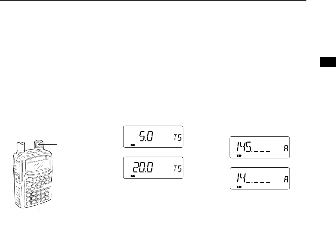
DSetting the tuning step
qPush [9 TS] for 1 sec. to enter tuning
step set mode.
•“TS” appears.
wRotate [DIAL] to select the desired
tuning step.
•Rotating the tuning dial while pushing [9
TS] also selects the tuning step.
•Tuning step can be set in VFO and
memory modes.
ePush [9 TS] or [VFO] to exit.
DMHz tuning step
This is useful to change the frequency
rapidly.
qSelect VFO mode with [VFO].
wPush [VFO MHz] for 1 sec. to select
1 MHz tuning step.
ePush [VFO MHz] for 1 sec. again to
select 10 MHz tuning step, if re-
quired.
rRotate [DIAL] to select the desired
MHz frequency.
tPush [VFO] to exit MHz tuning step.
FM SKIPP
FM SKIPP
1 MHz tuning step
10 MHz tuning step
5 kHz tuning step
20 kHz tuning step
[9 TS]
[DIAL]
[VFO MHz]
rr
BASIC OPERATION
IC-T90A_IM.qxd 02.5.28 01:13 PM Page 21 (1,1)
19
4BASIC OPERATION
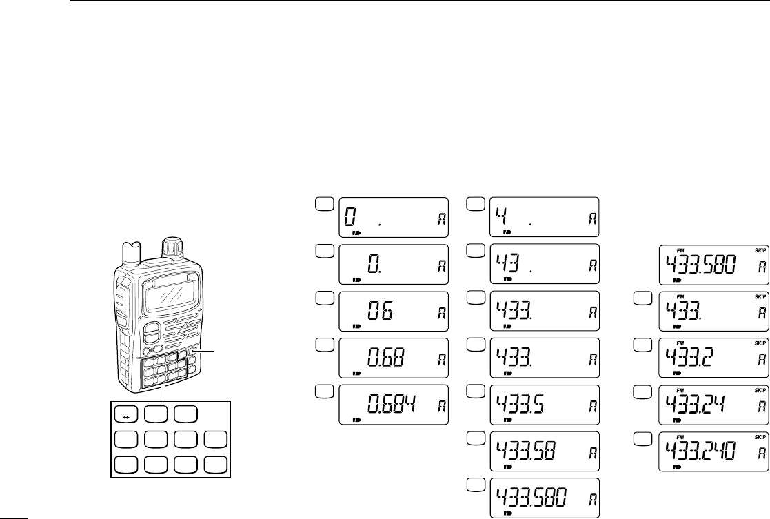
DSetting the frequency with keypad
qSelect VFO mode with [VFO].
wPush the desired numeral buttons until inputting 1 kHz digit to set the frequency.
•When you want to change the 100 kHz digit and below, push [•] first, then the numeral but-
tons.
•Acceptable digits for the 1 kHz digit depend on the 10 kHz digit.
■
Setting a frequency
Push numeral keys and [•] to input the
desired frequency.
•Frequency can be set irrelevant to the se-
lected band.
•When inputting a frequency outside of the
frequency range, the previously selected
frequency is automatically selected after in-
putting 1 kHz digit.
1
V D
2
TONE
3
H/L
4
DUP
5
SKIP
6
M.N
0
RIT
7
T.SCAN
8
SET
9
TS
.
DTMF.M
[VFO]
2
TONE
4
DUP
.
DTMF.M
0
RIT
6
M.N
8
SET
.
DTMF.M
FM
FM
FM
FM
FM
SKIPP
SKIPP
SKIPP
SKIPP
SKIPP
0
RIT
4
DUP
5
SKIP
3
H/L
3
H/L
4
DUP
8
SET
.
DTMF.M
FM
FM
FM
FM
FM
FM
FM
0
RIT
SKIPP
SKIPP
SKIPP
SKIPP
SKIPP
SKIPP
SKIPP
•Setting to 0.684 MHz
•Setting to 433.580 MHz
•Changing 100 kHz and
below.
Setting 433.580 MHz to
433.240 MHz.
IC-T90A_IM.qxd 02.5.28 01:13 PM Page 22 (1,1)
20
4
BASIC OPERATION
■Mode selection
DVFO mode
VFO mode is used for setting a desired
frequency within the band range.
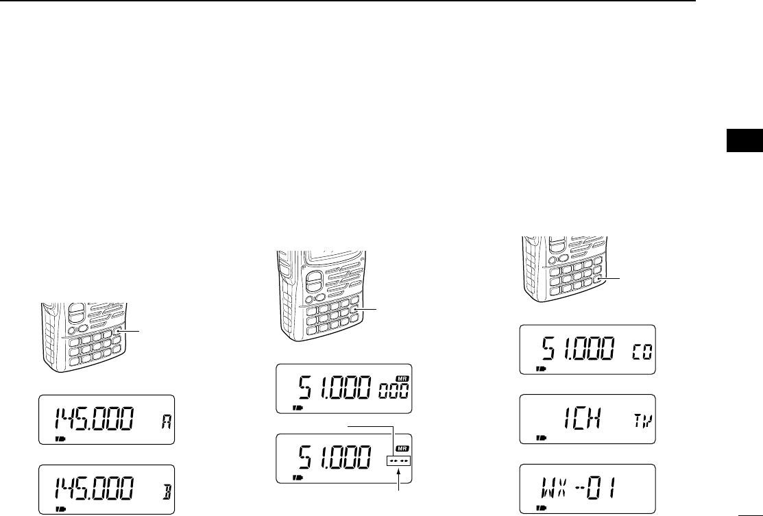
➥Push [VFO] to select VFO mode.
•Pushing [VFO] in VFO mode toggles
VFO A and B.
What is VFO?
VFO is an abbreviation of Variable Fre-
quency Oscillator. Frequencies for
transmitting and receiving are gener-
ated and controlled by the VFO.
DMemory mode
Memory mode is used for operation of
memory channels which have pro-
grammed frequencies.
➥Push [MR] to select memory mode.
•Pushing [MR] in memory mode toggles
memory channel and memory bank indi-
cations.
•To program a memory Ch, refer to p. 37.
DCall/TV/weather channels
Call channels are used for most-often-
used frequencies for quick recall. TV
and weather (U.S.A. version only)
channels can be selected with
[CALL/TV].
➥Push [CALL/TV] to select a call, TV
and weather channel in sequence.
FM
FM
[MR]
Memory channel
Memory bank
A00–Y99 appear when a
memory bank is programmed.
[VFO]
VFO A
VFO B
FM SKIPP
FM SKIPP
rr
BASIC OPERATION
FM
FMW
[CALL/TV]
Call channel
TV channel
Weather channel (U.S.A. only)
FM
IC-T90A_IM.qxd 02.5.28 01:13 PM Page 23 (1,1)
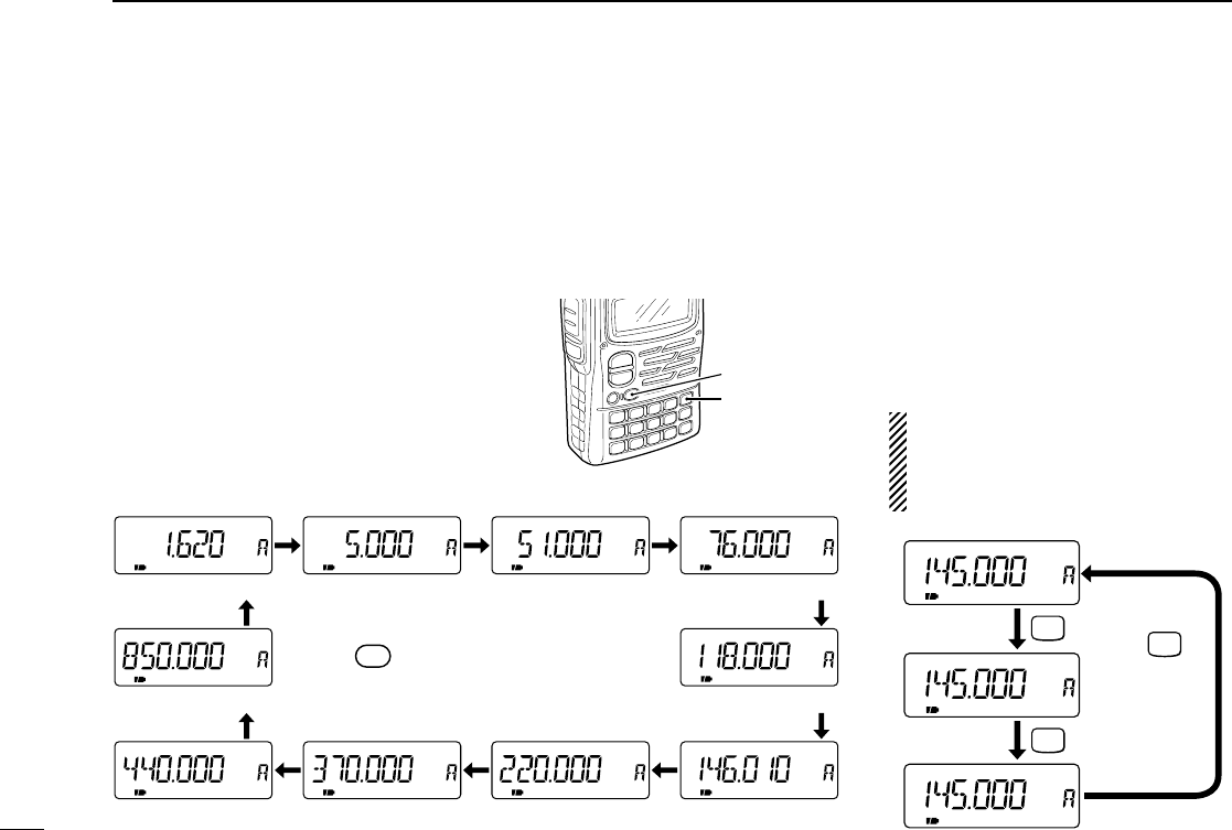
■Operating band and receive mode selection
DSelecting the operating
band
The transceiver can receive the BC
(broadcast) bands, 5M band, 50M
band, FM broadcast band, Air band, 2
m (VHF) band, 220M band, 300M band,
440M (UHF) band or 800M band.
*Frequency coverage depends on versions.
qSelect VFO mode with [VFO].
wPush [BAND] several times to select
the desired band.
•Rotating the tuning dial while pushing
[BAND] also selects the operating band.
[VFO]
[BAND]
21
4BASIC OPERATION
DSelecting the receive mode
Receive modes are determined by the
physical properties of the radio signals.
The transceiver has 3 receive modes:
FM, AM and WFM modes. Typically, AM
mode is used for the avionics band
(108–135.975 MHz) and WFM is used
for FM broadcast stations
(76–107.75 MHz).
When pushing [PTT], a beep tone
sounds indicating the mode is not
FM mode. The transceiver cannot
transmit in AM or WFM mode.
FM SKIPP
FM SKIPPW
AM SKIPP
FM mode
WFM mode
AM mode
MODE
SCAN
MODE
SCAN
MODE
SCAN
Push
to toggle the
operating
mode.
SKIPP
SKIPP
SKIPP
SKIPP SKIPP
SKIPPSKIPP
SKIPP
SKIPPAM FM
BAND
FM
FM
SKIPP
FM
AM
FM
FM
AM
FMW
BC (broadcast) bands 5M bands 50M band* WFM bands*
800M band
UHF band* 300M band
Air bands*
VHF band
220M band*
0.495–1.620 MHz 1.625–34.995 MHz 35.000–75.995 MHz*
108.000–135.975 MHz
76.000–107.750 MHz*
550.000–999.990 MHz
383.000–549.995 MHz 255.000–383.975 MHz 220.000–254.975 MHz 136.000–221.975 MHz
Push [BAND] several times to
select the desired band.
IC-T90A_IM.qxd 02.5.28 01:13 PM Page 24 (1,1)
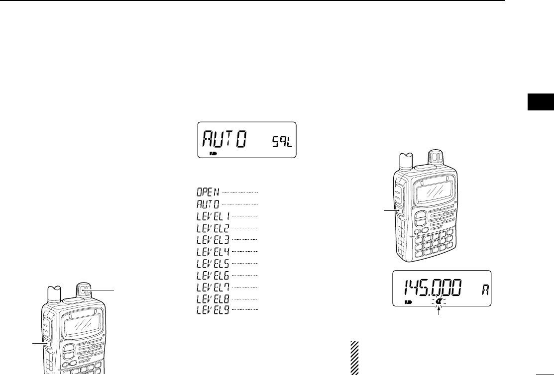
■Setting squelch level
22
4
BASIC OPERATION
The squelch circuit mutes the received
audio signal depending on the signal
strength. The transceiver has 9 squelch
levels, a continuously open setting and
an automatic squelch setting.
DSetting squelch level
qWhile pushing and holding [SQL], ro-
tate [DIAL] one-click to display the
currently squelch level.
wRotate [DIAL] successively to adjust
the squelch level.
•“LEVEL1” is loose squelch and
“LEVEL9” is tight squelch.
•“AUTO” indicates automatic level adjust-
ment with a noise pulse count system.
eRelease [SQL] to return to the previ-
ous indication.
[Squelch level indication]
DMonitor function
This function is used to listen to weak
signals or to open the tone squelch
manually.
➥Push and hold [SQL] to monitor the
operating frequency.
The [SQL] switch can be set as a
monitor ON/OFF switch in set mode.
(p. 60)
[SQL]
Blinks while monitoring.
FM SKIPP
rr
BASIC OPERATION
[SQL]
[DIAL]
Indication Squelch level
Open
Automatic (default)
Level 1 (loose)
Level 2
Level 3
Level 4
Level 5
Level 6
Level 7
Level 8
Level 9 (tight)
IC-T90A_IM.qxd 02.5.28 01:13 PM Page 25 (1,1)
23
4BASIC OPERATION
■Receiving
DSetting volume level
➥Push [Y] or [Z] to set the desired audio level.
•Rotating the tuning dial while pushing [Y] or [Z] also sets the
audio level.
DSetting squelch level
qWhile pushing [SQL], rotate [DIAL] to select the squelch
level.
•“LEVEL1” is loose squelch and “LEVEL9” is tight squelch.
wRelease [SQL] to return to the previous indication.
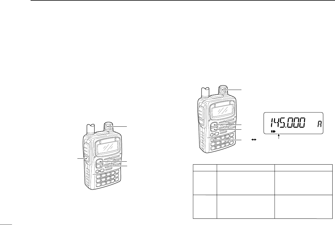
DExchange [DIAL] and [YY]/[ZZ] functions
The functions of tuning dial and [Y]/[Z] switches can be ex-
changed, if desired.
➥Push [1 V↔D] for 1 sec. to exchange the functions of the
tuning dial and [Y]/[Z] switches.
•“VOL” appears when the functions are exchanged.
[DIAL]
[Y]/[Z]
Default setting
Frequency setting
Memory channel setting
Scan direction setting
Set mode setting
Volume setting
Volume setting
Exchanged setting
Frequency setting
Memory channel setting
Scan direction setting
Set mode setting
FM
VOL
SKIPP
[DIAL]
[∫]
[√]
Appears when the functions
are exchanged.
[1 V D]
[DIAL]
[SQL] [∫]
[√]
IC-T90A_IM.qxd 02.5.28 01:13 PM Page 26 (1,1)
24
4
BASIC OPERATION
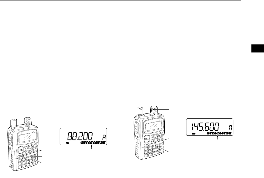
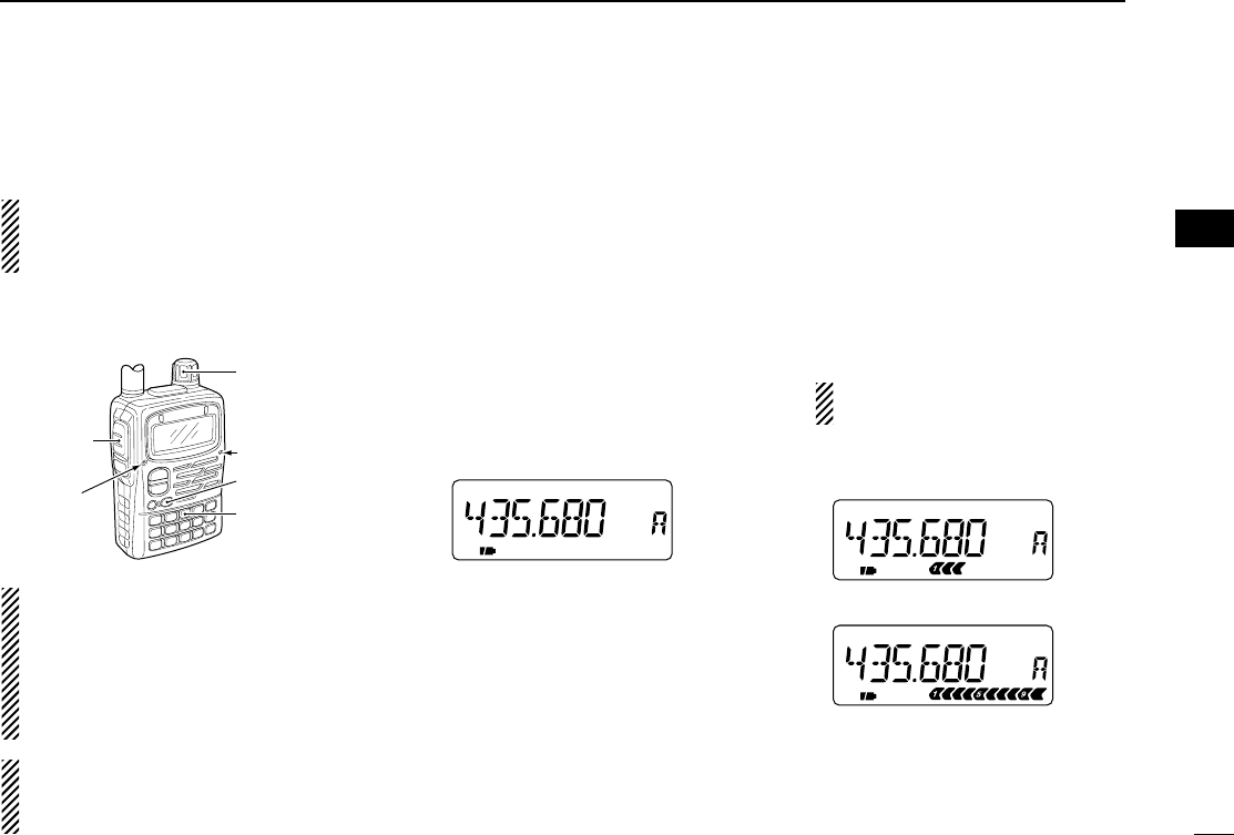
DReceiving FM broadcast
[EXAMPLE]: Receiving 88.200 MHz.
qSelect VFO mode with [VFO].
wFor direct frequency input, push [8], [8], [•], [2], [0], [0].
•Skip eand tin this case.
ePush [BAND] several times to select the FM broadcast
band.
•Default frequency (FM broadcast band): 76.000 or 88.000 MHz
rPush [MODE] several times to select WFM mode if re-
quired.
tRotate [DIAL] to set 88.200 MHz.
yWhen a signal is received:
➥The TX/RX indicator lights green.
➥Squelch opens and audio is emitted from the speaker.
➥The S/RF indicator shows the relative signal strength.
DReceiving amateur bands
[EXAMPLE]: Receiving 145.600 MHz.
qSelect VFO mode with [VFO].
wFor direct frequency input, push [1], [4], [5], [•], [6], [0], [0].
•Skip eand tin this case.
ePush [BAND] several times to select the 144 MHz band.
•Default frequency (144 MHz band): 145.000 MHz
rPush [MODE] several times to select FM mode if required.
tRotate [DIAL] to set 145.600 MHz.
yWhen a signal is received:
➥The TX/RX indicator lights green.
➥Squelch opens and audio is emitted from the speaker.
➥The S/RF indicator shows the relative signal strength.
FM SKIPP
[DIAL]
[VFO]
[MODE]
[BAND] S meter
FM SKIPPW
[DIAL]
[VFO]
[MODE]
[BAND] S meter
rr
BASIC OPERATION
IC-T90A_IM.qxd 02.5.28 01:13 PM Page 27 (1,1)

25
4BASIC OPERATION
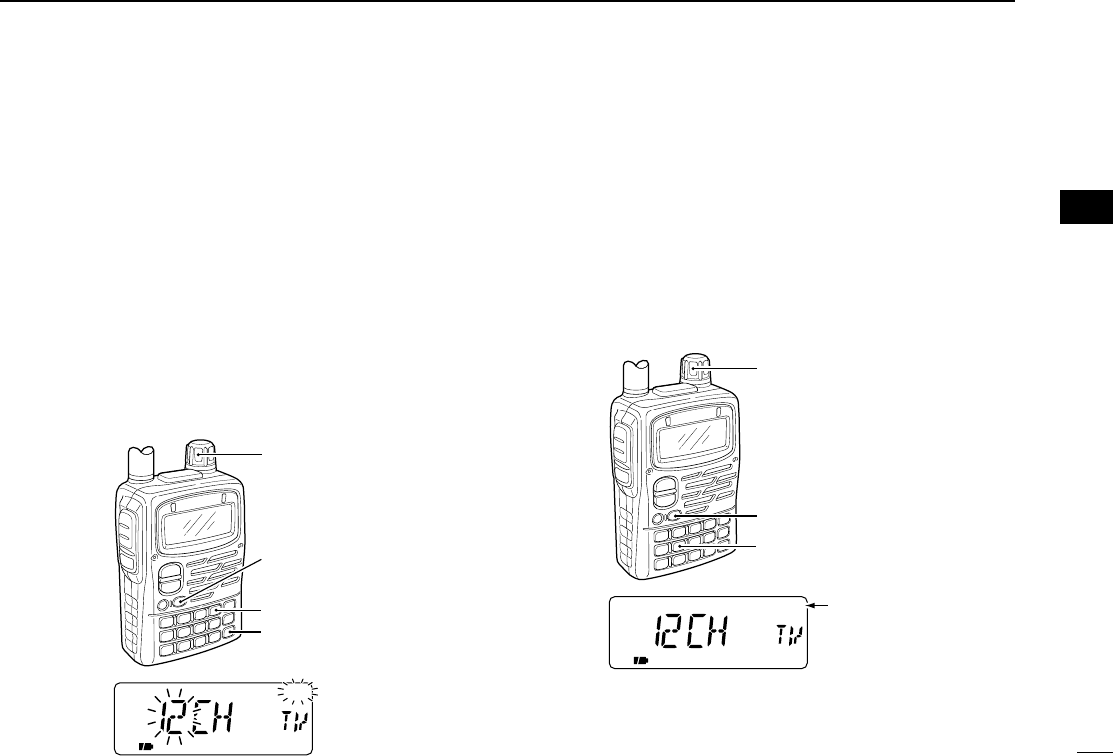
DReceiving TV channels
Available TV channels depends on the version. Refer to the
TV frequency table (p. 83) for details. Some channels are set
as skip channels. Refer to the skip channel setting (p. 26) for
details. TV channel frequency and skip setting can be re-pro-
grammed via the CS-T90A cloning soft ware, ask your dealer
for details.
qSelect TV mode with [CALL/TV].
•Pushing [CALL/TV] toggles a call, TV and weather channel
(p. 77; U.S.A. version only) in sequence.
wRotate [DIAL] to select the desired TV channel.
•Rotate [DIAL] while pushing [BAND] to select all TV channels.
eWhen a signal is received:
➥The TX/RX indicator lights green.
➥Squelch opens and audio is emitted from the speaker.
➥The S/RF indicator shows the relative signal strength.
Pushing [CALL/TV] selects the call channel and does not
return to the previous TV channel even if the previous
mode (VFO or memory) is selected from TV channel.
FMW
[BAND]
[DIAL]
[CALL/TV]
TV mode indicationTV channel indication
IC-T90A_IM.qxd 02.5.28 01:13 PM Page 28 (1,1)
26
4
BASIC OPERATION
DTV skip scan
The transceiver automatically programs the receivable TV
channels as non-skip channels and others as skip channels.
qSelect TV mode with [CALL/TV].
•Pushing [CALL/TV] selects a call, TV and weather channel
(U.S.A. version only) in sequence.
wPush [MODE SCAN] for 1 sec. to start TV skip scan.
•The transceiver automatically scans all TV channels.
eWhen the scan is finished:
➥The receivable TV channels have been programmed as non-
skip channels and others as skip channels.
➥Rotate [DIAL] to select the receivable TV channel.
➥Rotate [DIAL] while pushing [BAND] to select all TV channels.
DTV skip channel setting
The skip channel setting can be set manually.
qSelect TV mode with [CALL/TV].
•Pushing [CALL/TV] selects a call, TV and weather channel
(U.S.A. version only) in sequence.
wRotate [DIAL] while pushing [BAND] to select the desired
TV channel.
ePush [5 SKIP] for 1 sec. to toggle the skip setting.
•“SKIP” appears when the channel is set as skip channel.
FM SKIPW
[BAND]
[DIAL]
[5 SKIP]
Skip indication
FM SKIPW
[BAND]
[DIAL]
[CALL/TV]
[MODE SCAN]
rr
BASIC OPERATION
IC-T90A_IM.qxd 02.5.28 01:13 PM Page 29 (1,1)
27
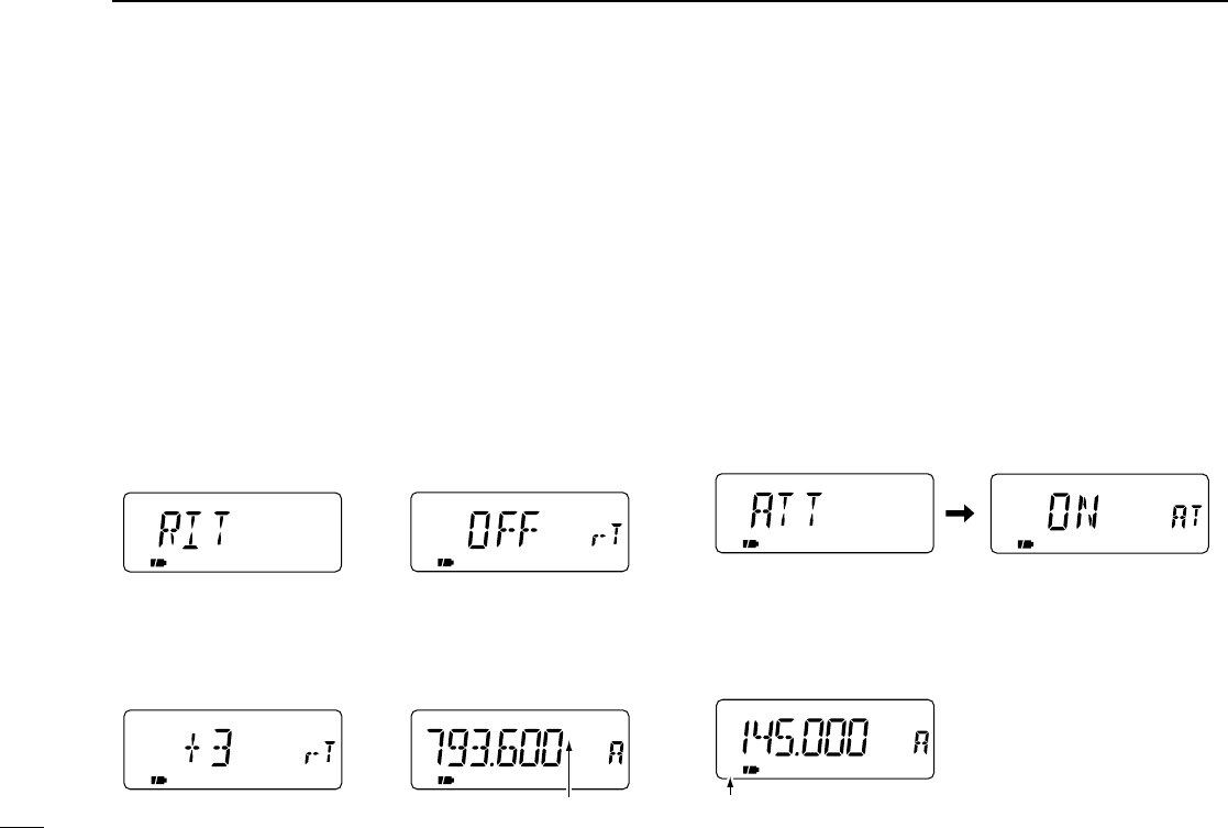
4BASIC OPERATION
■RIT function
To compensate for the off frequency of a transmitting station,
the transceiver has receive incremental tuning for receiving fre-
quencies above 630.000 MHz. The RIT function cannot be used
in TV mode and automatically cancelled below 630.000 MHz.
The receive incremental tuning (RIT) shifts only the receive
frequency within approx. ±5 kHz.
qSet an operating frequency above 630.000 MHz.
wPush [0 RIT] for 1 sec. to select the RIT set mode item.
•If “ATT” appears, rotate [DIAL] to select “RIT.”
ePush [0 RIT] again to select the RIT set mode.
rRotate [DIAL] to adjust the shift frequency.
•–5 to +5 appears while setting the shift frequency.
tPush [VFO] to exit the RIT set mode.
■Attenuator function
The attenuator prevents a desired signal from distorting when
very strong signals are near the desired frequency or when
very strong electric fields, such as from a broadcasting sta-
tion, are near your location. The attenuation level is approx.
10 dB.
qPush [0 RIT] for 1 sec. to select the ATT set mode item.
•“RIT” or “ATT” appears. If “RIT” appears, rotate [DIAL] to select
“ATT.” When the operating frequency is 629.995 MHz or below,
ATT set mode is automatically selected.
wPush [0 RIT] again to select the ATT set mode.
ePush [VFO] to exit the ATT set mode.
Attenuator is in use
FM SKIPP
ATT
ATT appears
If the operating frequency is
629.995 MHz or below, this
menu does not appear.
RIT/ATT selection menu Attenuator set mode
R
FM SKIPP
RIT indication
RIT frequency adjustment
Approx. +3 kHz shift
RIT function example
RIT function OFFRIT set mode
IC-T90A_IM.qxd 02.5.28 01:13 PM Page 30 (1,1)
28
4
BASIC OPERATION
■Transmitting
DAmateur band operation
CAUTION: Transmitting without
an antenna may damage the trans-
ceiver.
Make sure a charged battery pack or al-
kaline batteries are installed. (p. 1)
IMPORTANT: To maximize the read-
ability of your transmitted signal, pause
a few sec. after pushing [PTT], hold the
microphone 1 to 2 inches (2.5 to 5 cm)
from your mouth and speak at a nor-
mal voice level.
Protect circuit interrupts the output
power when over 11.5 V DC is con-
nected.
DOperating band and
frequency setting
qSelect VFO mode with [VFO].
wPush [BAND] several times to select
the desired amateur band.
•Rotating the tuning dial while pushing
[BAND] also selects the operating band.
eSet an operating frequency with the
tuning dial. (p. 19)
•To input the frequency directory, push
[4], [3], [5], [•], [6], [8] and [0] for the ex-
ample below.
DSelecting output power and
transmitting
qPush [3 H/L] for 1 sec. to select the
output power.
•Rotating the tuning dial while pushing
[3 H/L] also toggles the output power.
•“LOW” appears when low output power
is selected. If “LOW” does not appear,
high output power is selected.
wPush and hold [PTT] to transmit,
then speak into the microphone.
•TX/RX indicator lights red.
•The S/RF indicator shows the output
power selection.
•Approx.
output power:
4.5 W/0.5 W with 11 V DC (w/CP-19)
5.0 W/0.5 W with BP-217
0.1 W with BP-216 (fixed to low power)
The output power is fixed to low
while operating with battery case.
eRelease [PTT] to receive.
DFM narrow mode (transmit only)
The transceiver has narrow deviation
(±2.5 kHz) mode. Set narrow mode in
expanded set mode 2, if desired. (p. 66)
FM SKIPP
FM SKIPP
LOW
When LOW power is selected.
When HIGH power is selected.
FM SKIPP
Lights
red while
transmitting
[3 H/L]
[BAND]
Microphone
[DIAL]
[PTT]
rr
BASIC OPERATION
IC-T90A_IM.qxd 02.5.28 01:13 PM Page 31 (1,1)
29
4BASIC OPERATION
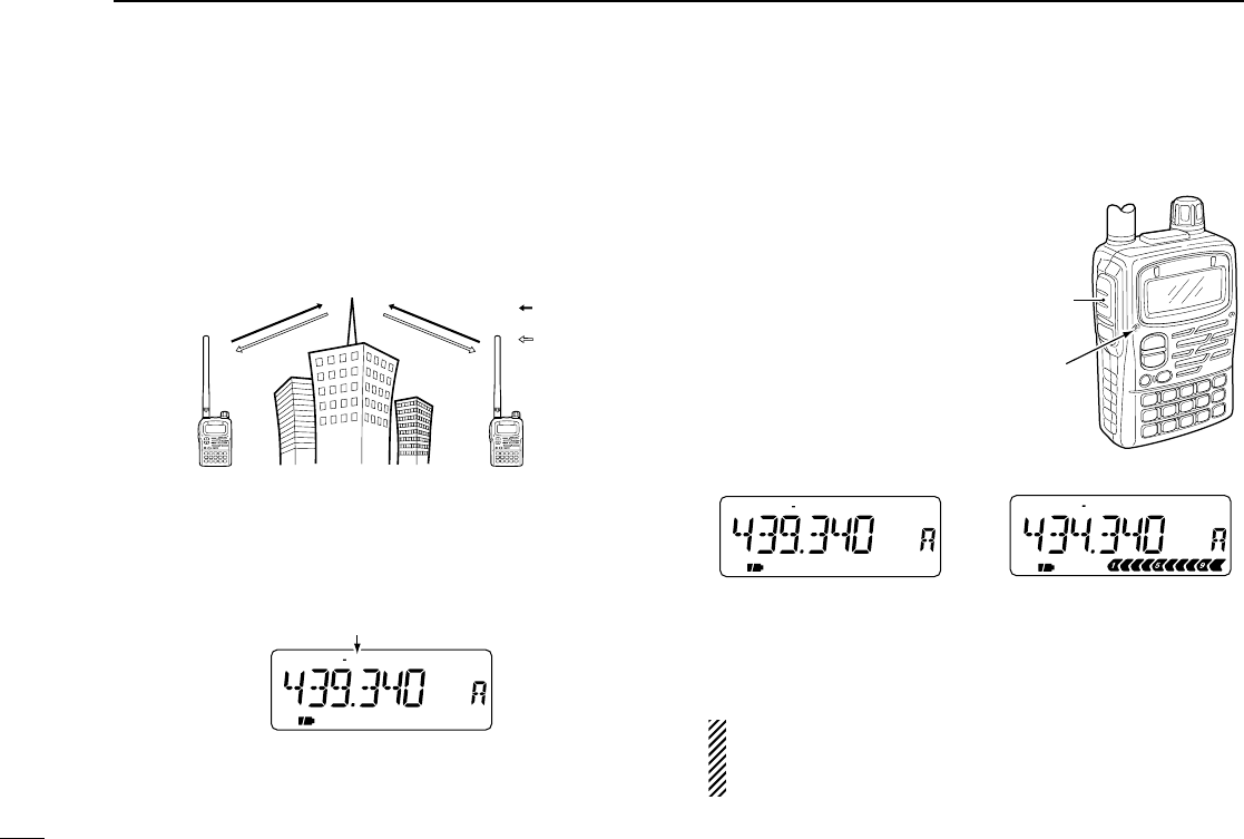
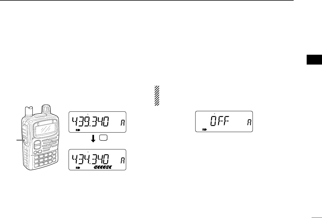
■Repeater operation
When using a repeater, the transmit frequency is shifted from
the receive frequency by the offset frequency. (p. 31) It is con-
venient to program repeater information into memory chan-
nels. (p. 37)
qSet the receive frequency (repeater output frequency).
wSet the shift direction of the transmit frequency. (–DUP or
DUP; see p. 31 for details.)
•When the auto repeater function is in use (U.S.A. and Korea ver-
sions only), this selection and step eare not necessary. (p. 33)
ePush [2 TONE] for 1 sec. to activate the subaudible tone
encoder, according to repeater requirements.
•“T” appears. Refer to p. 65 for tone frequency settings.
rPush and hold [PTT] to transmit.
•The displayed frequency au-
tomatically changes to the
transmit frequency (repeater
input frequency).
•If “OFF” appears, check the
offset frequency or shift di-
rection. (p. 31)
tRelease [PTT] to receive.
yPush and hold [SQL] to check whether the other station’s
transmit signal can be directly received or not.
U.S.A. and Korea versions:
Auto repeater function uses the settings of the repeater
tone frequency and offset frequency.
FM DUP SKIPTP
FM DUP SKIPTP
While receiving While transmitting
FM DUP SKIPTP
“DUP” appears.
Station A Station B
Repeater
439.340 MHz
434.340 MHz 434.340 MHz
439.340 MHz
Uplink
Downlink
(transmitting freq.)
(receiving freq.)
Lights
red while
transmitting.
[PTT]
IC-T90A_IM.qxd 02.5.28 01:13 PM Page 32 (1,1)
30
4
BASIC OPERATION
DChecking the repeater input signal
The transceiver can check whether the other station’s trans-
mit signal can be received directly or not.
➥Push and hold [SQL] to check whether the other station’s
transmit signal can be directly received or not.
•When the other station’s signal can be directly received, move to
a non-repeater frequency with simplex. (duplex OFF)
DOff band indication
If the transmit frequency is out of the amateur band, the off
band indication “OFF” appears on the display when [PTT] is
pushed. Check the offset frequency or duplex direction in this
case. (p. 31)
U.S.A. and Korea versions:
Auto repeater function uses the setting of the offset fre-
quency.
➲CONVENIENT
Tone scan function: When you don’t know the subaudible
tone used for a repeater, the tone scan is convenient for de-
tecting the tone frequency.
➥Push [7 T.SCAN] for 1 sec. to activate. See p. 73 for more
information.
DUP T
FM SKIPP
SQL
FM DUP SKIPTP
FM DUP SKIPTP
[SQL]
Indication while receiving
Receives –5 MHz shift frequency
rr
BASIC OPERATION
IC-T90A_IM.qxd 02.5.28 01:13 PM Page 33 (1,1)
31
4BASIC OPERATION
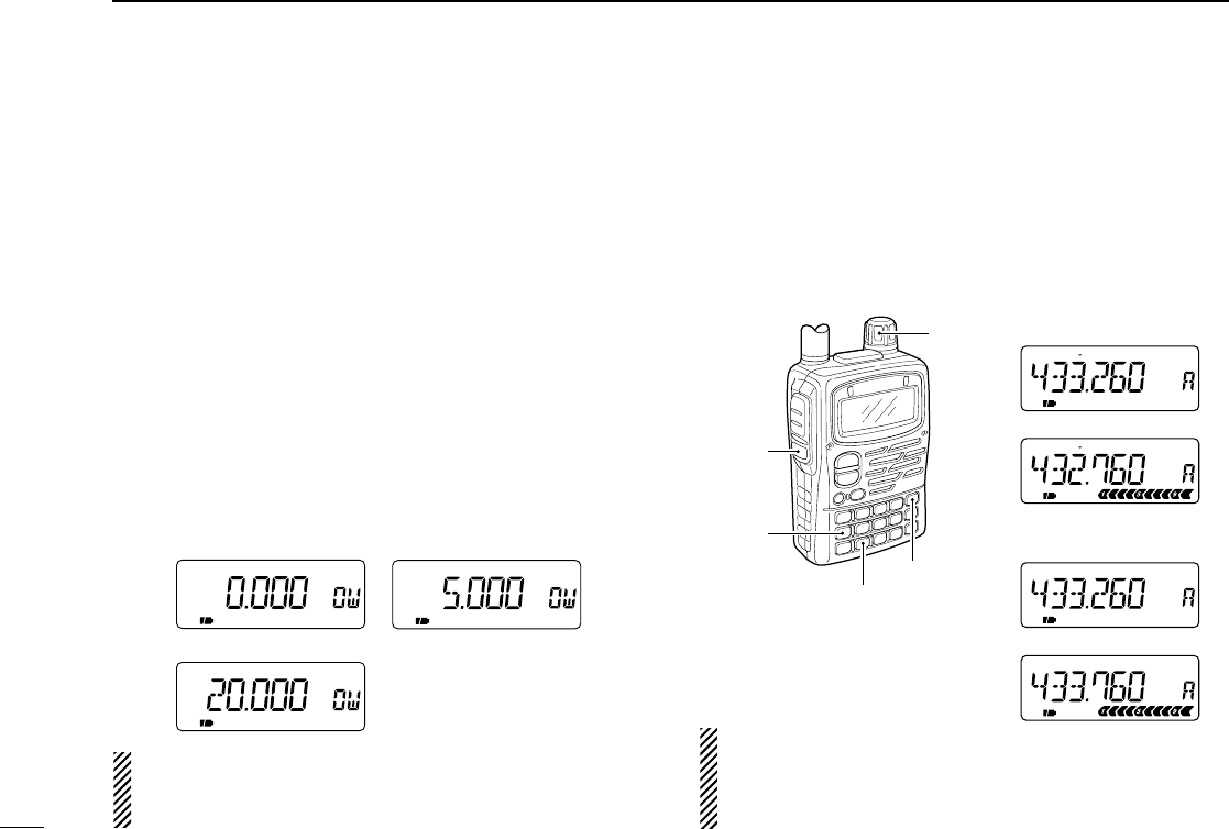
■Duplex operation
DSetting offset frequency
When communicating through a repeater, the transmit fre-
quency is shifted from the receive frequency by an amount
determined by the offset frequency.
qSelect VFO mode or desired memory channel to be pro-
grammed.
wPush [8 SET] for 1 sec. to enter set mode.
eRotate [DIAL] until “OFFSET” appears.
rPush [8 SET] again to select offset frequency.
tRotate [DIAL] to set the desired offset frequency.
•The tuning step becomes the selected tuning step.
•Push [VFO MHz] for 1 sec. to use the MHz tuning step, if desired.
yPush [VFO] to exit set mode.
U.S.A. and Korea versions:
Auto repeater function uses the setting of the offset fre-
quency. Take care the offset frequency. (p. 33)
DSetting duplex direction
➥Push [4 DUP] for 1 sec. to select “– DUP” or “DUP”.
•“–DUP” or “DUP” indicates the transmit frequency for minus shift
or plus shift, respectively.
•When offset frequency
is 500 kHz.
U.S.A. and Korea versions:
Auto repeater function has priority over the manual duplex
setting. If the frequency changes after setting, the auto re-
peater function may change the duplex setting.
FM DUP SKIPTP
FM DUP SKIPTP
FM DUP SKIPTP
FM DUP SKIPTP
–Duplex example
+Duplex example
Receiving
Receiving
Transmitting
Transmitting
[SQL]
[4 DUP]
[DIAL]
[8 SET]
[VFO MHz]
5.0 MHz offset
20.0 MHz offset
No offset frequency
IC-T90A_IM.qxd 02.5.28 01:13 PM Page 34 (1,1)
32
4
BASIC OPERATION
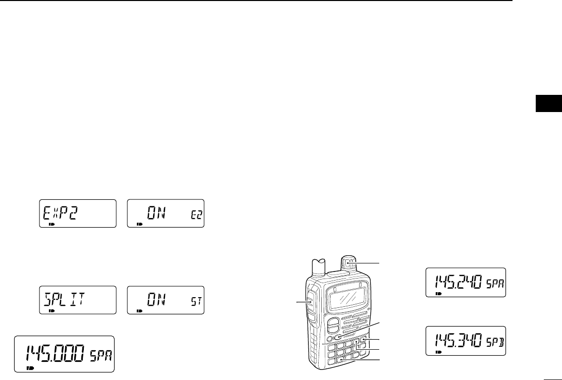
■Split operation
Split frequency operation allows you to transmit and receive
on two different frequencies in the same band. The split fre-
quency operation is performed using 2 frequencies one in
VFO A and one in B.
DSetting split frequency operation
qPush [8 SET] for 1 sec. to enter set mode.
wRotate [DIAL] until “EXP2” appears.
ePush [8 SET] to select expanded set mode 2.
rRotate [DIAL] to turn the expanded set mode 2 ON.
tPush [8 SET] to exit expanded set mode 2.
yRotate [DIAL] until “SPLIT” appears.
uPush [8 SET] to select split function.
iRotate [DIAL] to select split function ON or OFF.
oPush [VFO] to exit set mode.
•“SPA” or “SPB” appears and
the split frequency operation is
activated.
DSplit frequency operation example
[EXAMPLE]: VFO A FM 145.240 MHz
VFO B FM 145.340 MHz
qPush [VFO] several times to select VFO A.
•Pushing [VFO] toggles VFO A and B.
wPush [BAND] several times to select the 144 MHz band.
ePush [MODE] several times to select FM mode.
rSet the operating frequency to 145.240 MHz with the tun-
ing dial.
tPush [VFO] to select VFO B.
yPush [BAND] several times to select the 144 MHz band.
uPush [MODE] several times to select FM mode.
iSet the operating frequency to 145.340 MHz.
oPush [PTT] to start the split frequency operation.
FM SKIPP
SKIPPFM
[DIAL]
[PTT]
[BAND]
[MODE]
[VFO]
[8 SET]
VFO A
VFO B
FM SKIPP
rr
BASIC OPERATION
IC-T90A_IM.qxd 02.5.28 01:13 PM Page 35 (1,1)
33
4BASIC OPERATION
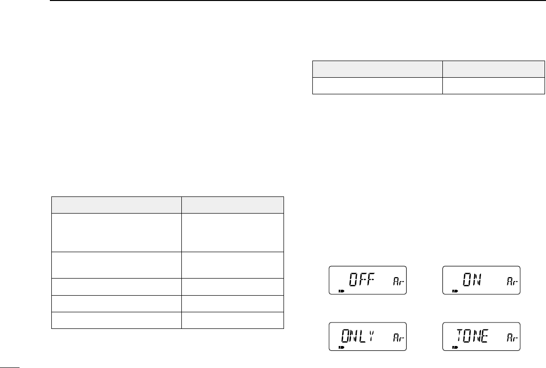
■Auto repeater function
(U.S.A. and Korea versions only)
The U.S.A. and Korea versions automatically activate the re-
peater settings (duplex ON/OFF, duplex direction, tone en-
coder ON/OFF) when the operating frequency falls within or
outside of the general repeater output frequency range. The
offset and repeater tone frequencies are not changed by the
auto repeater function, reset these frequencies, if necessary.
DFrequency range and offset direction
•U.S.A. version
•Korea version
qSelect VFO mode with [VFO].
wPush [8 SET] for 1 sec. to enter set mode.
eRotate [DIAL] until “AUTO RP” appears.
rPush [8 SET] to select auto repeater set mode.
tRotate [DIAL] to turn the auto repeater function ON (DUP
ONLY or DUP TONE) or OFF.
U.S.A. version:
•“DUP ONLY”Activates duplex only.
•“DUP TONE”Activates duplex and tone.
•“OFF”Auto repeater function is turned OFF.
Korea version:
•“ON”Activates duplex and tone.
•“OFF”Auto repeater function is turned OFF.
yPush [VFO] to exit set mode.
DUPDUP
Duplex activated only. Duplex and tone activated.
Duplex and tone activated.Auto repeater function
is turned OFF.
FREQUENCY RANGE SHIFT DIRECTION
439.000–440.000 MHz “–DUP” appears
FREQUENCY RANGE SHIFT DIRECTION
151.620–151.995 MHz
152.500–152.995 MHz
153.500–153.995 MHz
“–DUP” appears
147.000–147.395 MHz “DUP” appears
442.000–444.995 MHz “DUP” appears
447.000–449.995 MHz “–DUP” appears
145.200–145.495 MHz
146.610–146.995 MHz “–DUP” appears
IC-T90A_IM.qxd 02.5.28 01:13 PM Page 36 (1,1)

34
4
BASIC OPERATION
■1750 Hz tone
Some European repeaters require a 1750 Hz tone to be ac-
cessed. For such European repeaters, perform the following.
•This tone can be use as a ‘Call signal’out of Europe countries.
qPush [• DTMF.M] for 1 sec. to select DTMF memory.
wRotate [DIAL] counter-clockwise until “T-CALL” appears.
ePush [VFO] to exit DTMF memory.
rSet the receive frequency (repeater output frequency).
tSet the shift direction of the transmit frequency. (–DUP or
DUP; see p. 31 for details.)
yWhile pushing [PTT], push [SQL] for 1 to 2 sec. to transmit
a 1750 Hz tone burst signal.
•If “OFF” appears, check the offset frequency or shift direction.
(p. 31)
•The displayed frequency automatically changes to the transmit
frequency (repeater input frequency).
uPush and hold [PTT] to transmit.
iRelease [PTT] to receive.
oPush and hold [SQL] to check whether the other station’s
transmit signal can be received directly or not.
rr
BASIC OPERATION
IC-T90A_IM.qxd 02.5.28 01:13 PM Page 37 (1,1)

35
5MEMORY/CALL CHANNELS
■General
The transceiver has 500 memory channels, 50 scan edge
channels and 5 call channels for storage of often-used fre-
quencies.
Memory channels can be named with 6 characters and as-
signed to 18 banks.
DMemory/call channel contents
The following information can be programmed into memory
or call channels:
•Operating frequency (p. 19)
•Receive mode (p. 21)
•Tuning step (p. 18)
•Duplex direction (DUP or –DUP) with an offset frequency
(p. 31)
•Subaudible tone encoder, tone squelch or DTCS squelch
ON/OFF (pgs. 29, 71)
•Subaudible tone and tone squelch frequencies (p. 70)
•DTCS code with code phase mode (pgs. 65, 70)
•Memory bank (p. 41)
•Memory name (p. 39)
•Scan skip setting (p. 48)
DDefault memory contents example
CHANNEL DESCRIPTION
000–499
(Memory
channel; Mch)
•Regular memory channel
•Default memory channel example
Mch 000 151.000 MHz
Mch 001 145.000 MHz
Mch 002 430.000 MHz
*Mch 003–499 are blank channels.
0A/0B–
24A/24B
(Scan edge
channel)
•Program scan edge channel
25 pairs (50 channels)
•Default scan edge example
0A: 1110.495 MHz 0B: 440.000 MHz
1A: 1150.000 MHz 1B: 1152.000 MHz
2A: 1144.000 MHz 2B: 1146.000 MHz
3A: 1430.000 MHz 3B: 1440.000 MHz
11
*4A/4B–24A/24B are blank channels.
C0–C4
(Call channel)
•Calling channel for amateur bands
•
Can be used as regular memory channel
•Default call channel example
C0 151.000 MHz
C1 145.000 MHz
C2 430.000 MHz
*C3 and 4 are blank channels.
IC-T90A_IM.qxd 02.5.28 01:13 PM Page 38 (1,1)
36
5
MEMORY/CALL CHANNELS
■Calling up memory channels
Memory channels can be selected with
the [DIAL] and keypad.
•Blank channels cannot be selected via
[DIAL].
•Blank channels can be selected via key-
pad.
•Previously selected channels appear
when the wrong memory channel num-
ber is entered.
DSelecting with tuning dial
qPush [MR] to select memory mode.
wRotate [DIAL] to select the desired
memory channel.
DSelecting with keypad
qPush [MR] to select memory mode.
wPush the desired numeral keys to
select the desired memory channel.
•Selecting memory channel 001.
Push [0], [0] and [1].
•Selecting memory channel 056.
Push [0], [5] and [6].
•Selecting memory channel 499.
Push [4], [9] and [9].
➲CONVENIENT
The memory channels (000–099) can
be selected with 1 or 2 digits plus [MR].
•Selecting memory channel 005.
Push [5] and [MR].
•Selecting memory channel 024.
Push [2], [4] and [MR].
DCheck contents of all
memory channels
qPush [MR S.MW] for 1 sec. to enter
memory write condition.
•Memory channel readout flashes.
wRotate [DIAL] to check the desired
memory channel.
Rotating [DIAL] while pushing
[BAND] also selects all memory
channels.
FM
FM
Memory mode indication
Memory channel number
Appears
[DIAL]
[MR S.MW]
1
V D
2
TONE
3
H/L
4
DUP
5
SKIP
6
M.N
0
RIT
7
T.SCAN
8
SET
9
TS
keypad
tt
MEMORY/CALL CHANNELS
IC-T90A_IM.qxd 02.5.28 01:13 PM Page 39 (1,1)
37
5MEMORY/CALL CHANNELS
Program the desired frequency into a memory channel, call
channel or scan edge channel as follows.
The memory channels are shared with all bands. Memory
channels 003–499 are blank (non-programmed) channels as
a factory setting.
DProgramming a memory channel
[EXAMPLE]: 433.520 MHz into Mch 11
qSelect VFO mode with [VFO].
wSet the desired frequency:
➥Select the desired band with [BAND].
➥Set the frequency using [DIAL].
➥Set other data (e.g. offset frequency, duplex direction,
subaudible tone frequency, etc.), if required.
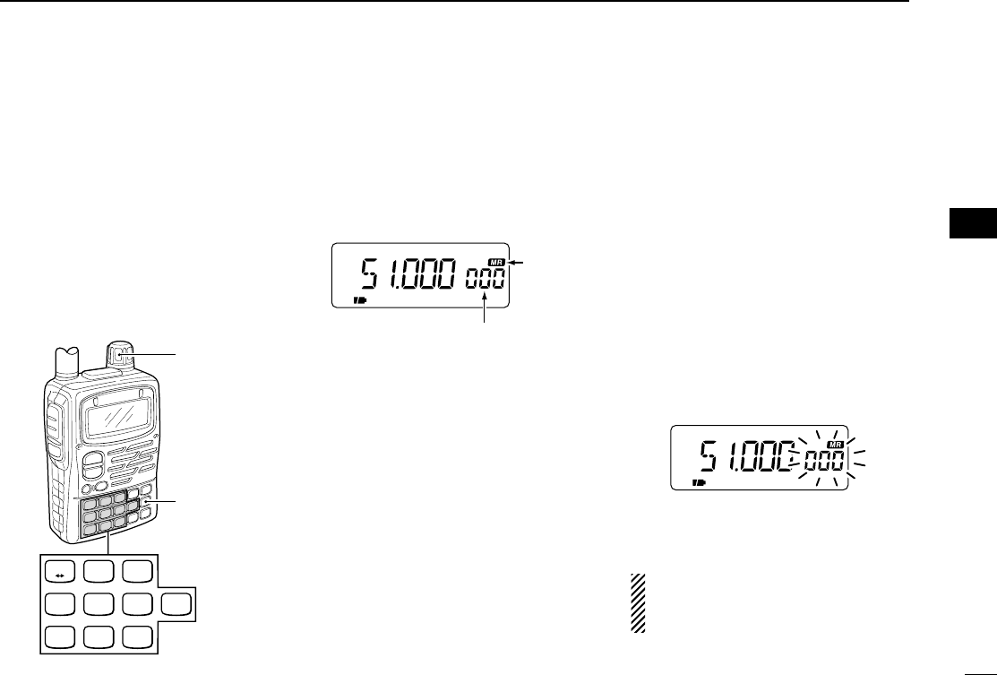
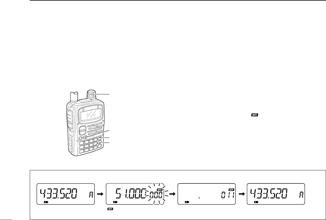
ePush [MR S.MW] for 1 sec. to indicate memory channels.
•Memory channel indicator “” and channel readout blinks.
•Do not hold [MR S.MW] for more than 2 sec., otherwise the pre-
viously selected memory channel will be overwritten.
rRotate [DIAL] to select the desired channel.
•Call channels (C0–C4), VFO (VF) and scan edge channels
(0A/0B–24A/24B), as well as regular memory channels, can be
programmed in this way.
tPush [MR S.MW] for 1 sec. to program.
[DIAL]
[MR S.MW]
[VFO]
[BAND]
FM
FM SKIPPFM SKIPP
e Push [MR S.MW] for 1 sec. r Select the desired channel. t Push [MR S.MW] for 1 sec.
VFO mode is selected after writing.
“ ” and memory channel
readout blinks.
q, w Set the frequency.
■
Programming m
emory channels
IC-T90A_IM.qxd 02.5.28 01:13 PM Page 40 (1,1)
38
5
MEMORY/CALL CHANNELS
DAuto memory channel increment
While programming a memory channel, the next memory
channel can be selected automatically. This is convenient
when programming memory channels one after another.
➥Keep pushing [MR S.MW] for 2 sec. or more, at step tof
the left section, to select the next memory channel auto-
matically.
■Transferring memory
contents to VFO
This is convenient when operating around a memory or call
channel.
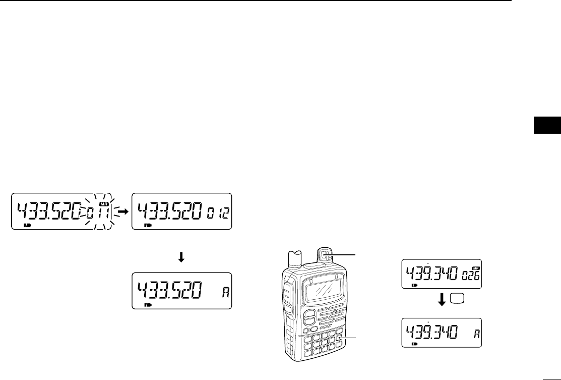
qPush [VFO] several times to select VFO A or B to be trans-
ferred.
wPush [MR] to select memory mode.
eSet the desired memory channel with [DIAL].
•Call or scan edge channel contents can be transferred in the
same manner. Select a call channel in this case.
rPush [MR S.MW] for 2 sec. to transfer.
[EXAMPLE]: Transferring memory channel 26 to VFO A.
MR
S.MW
FM DUP SKIPT
FM DUP T
P
[DIAL]
[MR]
Select the desired Mch.
for 2 sec.
Transfer to VFO.
FM SKIPP
FM SKIPP
FM
Keep pushing [MR S.MW].Push [MR S.MW] for 1 sec.
VFO is selected.
Next memory channel is
automatically selected.
tt
MEMORY/CALL CHANNELS
IC-T90A_IM.qxd 02.5.28 01:13 PM Page 41 (1,1)
39
5MEMORY/CALL CHANNELS
■Copying memory contents
This is convenient when programming memory contents into
a scan edge channel or call channel.
•Call or scan edge channel contents can be copied in the same
manner.
q
Push [MR S.MW]
to select memory mode.
wSelect the memory channel to be copied with [DIAL].
e
Push [MR S.MW] for 1 sec.
•Memory channel indicator and number blinks.
•Do not hold [MR S.MW] for more than 2 sec., otherwise the pre-
viously selected VFO will be overwritten.
rRotate [DIAL] to select the target memory channel.
tPush [MR S.MW] for 2 sec. to copy.
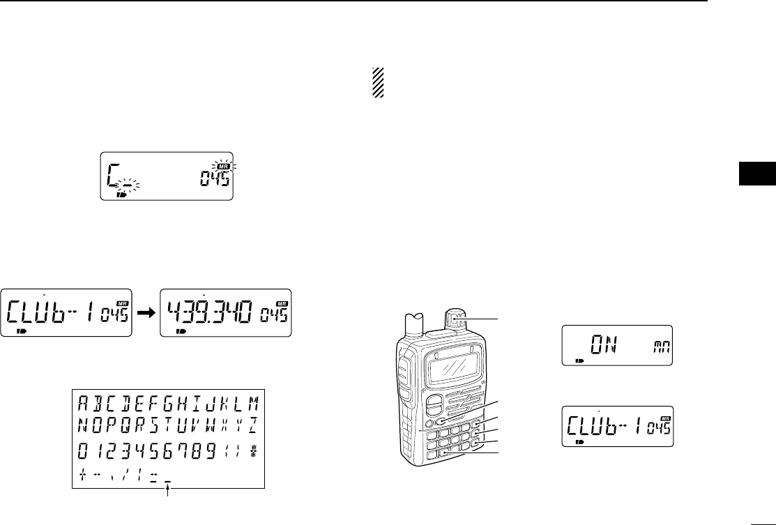
■Memory names
Each memory, scan edge and call channels can be pro-
grammed with an alphanumeric name such as a repeater
name, club name, etc., for easy recognition. Names can be
a maximum of 6 characters—see the table at right for avail-
able characters.
DMemory name input
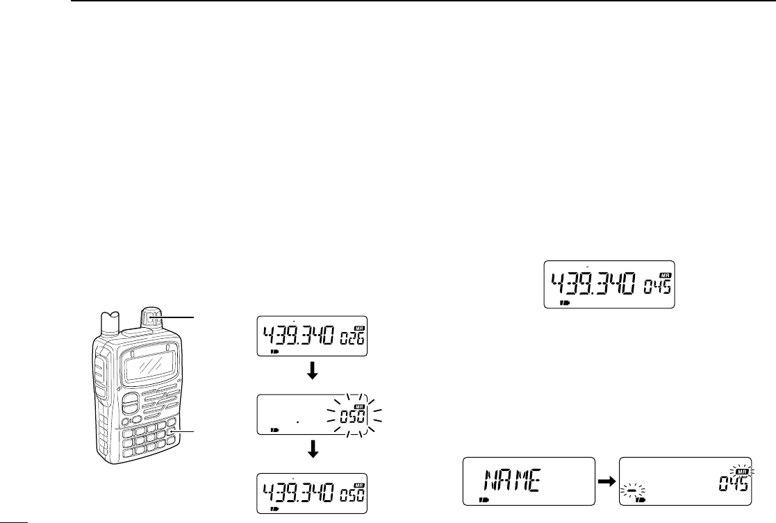
qPush [MR] to select memory mode.
wSet the desired memory channel with [DIAL].
e
Push [MR S.MW] for 1 sec. to indicate the memory channel.
•Memory channel indicator flashes.
•Do not hold [MR S.MW] for more than 2 sec., otherwise the pre-
viously selected VFO will be overwritten.
rPush [CALL/TV] several times to select “NAME.”
•Memory name screen appears. The 1st character of the name
and “X” flashes.
•Previously programmed name appears, if programmed.
FM DUP T
FM DUP T
FM DUP T
[DIAL]
[MR]
Select a channel to copy.
Select desired channel.
Write into the channel.
IC-T90A_IM.qxd 02.5.28 01:13 PM Page 42 (1,1)
40
5
MEMORY/CALL CHANNELS
tRotate the tuning dial to select the desired character.
•See the following list for available characters.
yPush [BAND] to advance the cursor.
•Rotating the tuning dial while pushing [BAND] also selects the
cursor.
uRepeat tand yuntil the desired name is input.
iPush [VFO] to program the name.
oIf you want to set other channels, repeat wthrough ito
set the desired name.
•Available characters
The memory names are automatically programmed into
the memory channels.
DMemory name indication
Turn the memory name indication ON and OFF as follows.
➥Push [6 M.N] for 1 sec. to toggle the memory name indi-
cation ON and OFF.
•Frequencies are displayed for the memory channels which do
not have memory names. You cannot display both.
•To change the memory name, program a new memory name
again.
FM DUP T
[DIAL]
[BAND]
[MR]
[VFO]
[CALL/TV]
[8 SET]
Memory name ON
Memory name indication
Space
FM DUP T FM DUP T
tt
MEMORY/CALL CHANNELS
IC-T90A_IM.qxd 02.5.28 01:13 PM Page 43 (1,1)
41
5MEMORY/CALL CHANNELS
■Memory bank
The transceiver has 500 memory channels that can be as-
signed to 18 banks for faster memory access, memory
arrangement, etc.
Each bank (A–H, J, L, N–R, T, U and Y) can be assigned up
to 100 memory channels.
Memory bank is used for arrangement of a memory chan-
nel. When you edit the original memory channel contents,
the memory bank contents are updated automatically.
DSetting memory bank
qPush [MR] to select memory mode.
wSet the desired memory channel with [DIAL].
ePush [MR S.MW] for 1 sec. to indicate a memory channel.
•Memory channel indicator flashes.
•Do not hold [MR S.MW] for more than 2 sec., otherwise the pre-
viously selected VFO will be overwritten.
rPush [CALL/TV] several times to select “BANK.”
•Memory bank screen appears.
•Previously programmed memory bank appears, if programmed.
tPush [BAND] to select a memory bank.
•Rotating the tuning dial while pushing [BAND] also selects the
memory bank.
•Select “-- -- -- --” to clear the memory bank information.
yRotate the tuning dial to select the desired channel.
•Previously used memory bank channel cannot be selected.
uPush [VFO] to program the memory bank channel.
000 51.000 MHz
001 145.000 MHz
002 433.000 MHz
003 145.120 MHz
004 435.340 MHz
005 145.040 MHz
006 433.560 MHz
007 850.480 MHz
008 52.560 MHz
009 1.620 MHz
010 50.140 MHz
011 118.200 MHz
012 76.500 MHz
013 118.125 MHz
014 145.540 MHz
015 369.850 MHz
016 434.720 MHz
017 848.98750 MHz
018 852.720 MHz
019 75.795 MHz
020 127.700 MHz
021 146.300 MHz
499 119.870 MHz
A00–99 144 MHz Repeater*
B00–99 440 MHz Repeater*
C00–99 VHF air frequencies
D00–99
E00–99
F00–99
G00–99
H00–99
J00–99
L00–99
N00–99
O00–99
P00–99
Q00–99
R00–99
T00–99
U00–99
Y00–99
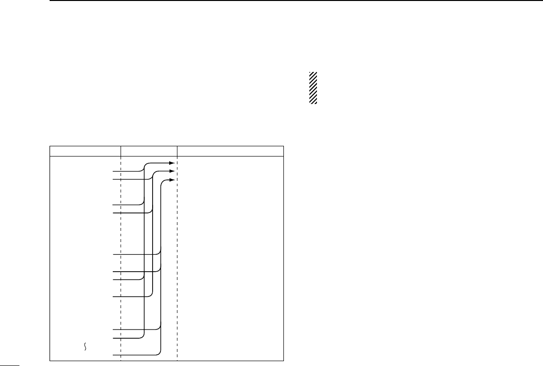
Mch contents Memory bank contents
A00
B00
A01
B01
C00
C01
A02
B02
C02
A03
C03
Memory bank
*Above sample is collected 144
MHz Repeater channels to bank A
and 440 MHz Repeater channels
to bank B.
IC-T90A_IM.qxd 02.5.28 01:13 PM Page 44 (1,1)
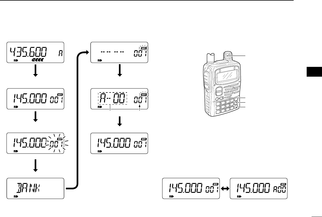
42
5
MEMORY/CALL CHANNELS
FM
FM
FM
FM
FM
q
Push [MR] to select memory mode.
w Select Mch with [DIAL].
e Push [MR S.MW] for 1 sec. to
indicate Mch.
VFO mode
Memory channel indicator flashes.
Release [CALL/TV].
u
Push
[VFO].
Memory bank is programmed and
memory mode is selected.
Memory bank indication
Memory channel indication
t
Push
[BAND]
to select memory bank.
y Rotate [DIAL] to select
memory bank channel
.
r Push [CALL/TV].
Each push selects BANK, NAME,
SKIP, CLEAR and S.MW in sequence.
Memory bank and
channel.
FM SKIPP
Selected memory channel.
[DIAL]
[BAND]
[MR S.MW]
[CALL/TV]
➥Push [BAND] to select the memory bank in sequence.
➥Pushing [MR] toggles the memory channel indication
and memory bank indication.
tt
MEMORY/CALL CHANNELS
IC-T90A_IM.qxd 02.5.28 01:13 PM Page 45 (1,1)
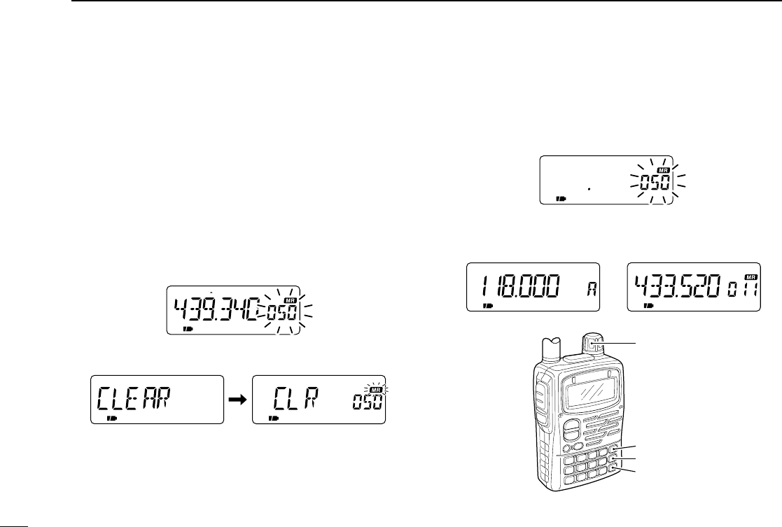
43
5MEMORY/CALL CHANNELS
■Memory clear
Unwanted memory channels can be cleared (erased). Before
clearing a memory channel make sure it is no longer needed
as cleared memories cannot be recalled. Scan edges (0A/0B)
cannot be cleared.
qPush [MR S.MW] for 1 sec. to indicate a memory channel.
•Memory channel indicator flashes.
•Do not hold [MR S.MW] for more than 2 sec., otherwise the pre-
viously selected VFO or memory channel will be overwritten.
wSelect the memory channel to be cleared with [DIAL].
•Scan edges (0A/0B) cannot be cleared.
ePush [CALL/TV] several times to select “CLEAR.”
rPush [MR S.MW] for 1 sec. to clear the selected memory
channel.
•3 beeps sound, then the frequency is cleared.
tPush [VFO] to return to the previous mode.
[DIAL]
[VFO]
[CALL/TV]
[MR S.MW]
FMAM SKIPP
VFO mode Memory mode
FM DUP T
IC-T90A_IM.qxd 02.5.28 01:13 PM Page 46 (1,1)
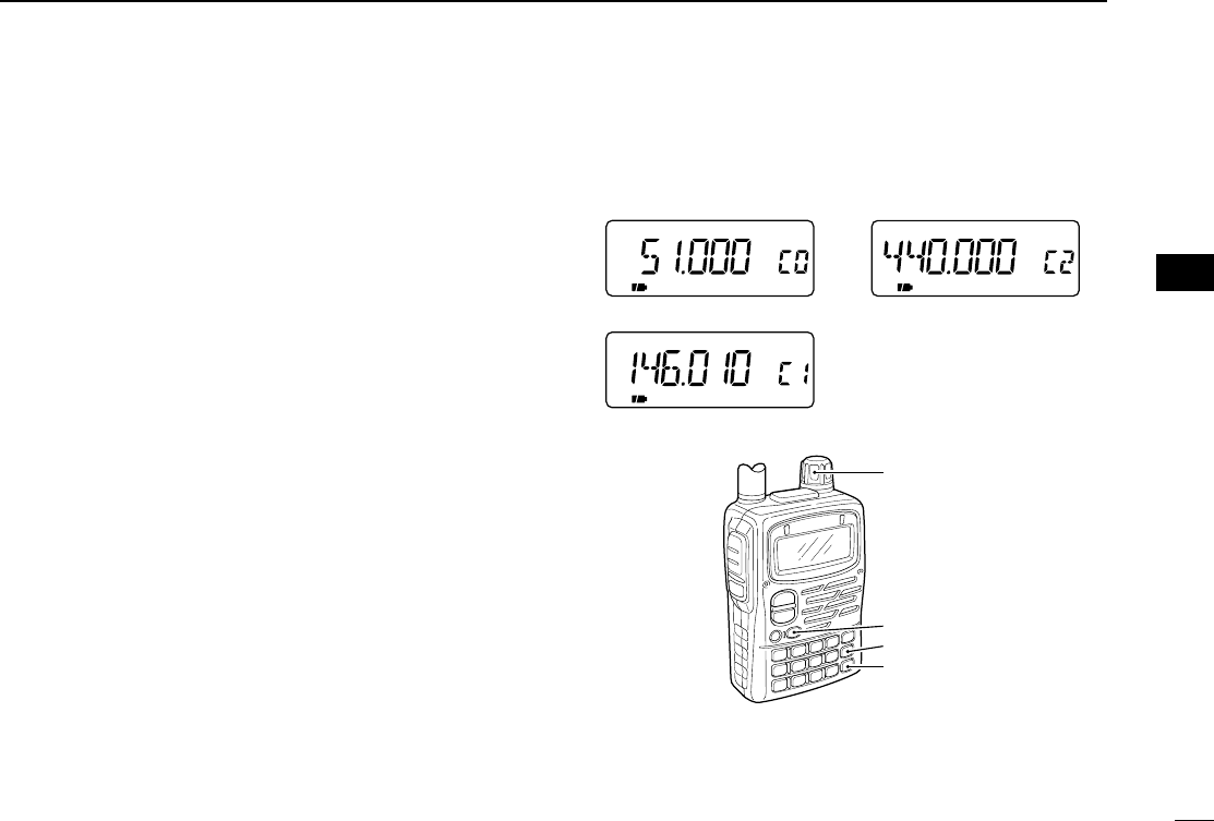
44
5
MEMORY/CALL CHANNELS
■Call channel
5 call channels are available to store the most-often-used fre-
quencies for quick recall.
The call channels can be programmed in a similar manner to
memory channel programming.
➥Select C0–C4 for programming call channel 0–4 in step r
in “Programming a memory channel.” (p. 37)
DSelecting a call channel
qPush [CALL/TV] to select a call channel.
•Pushing [CALL/TV] selects a call, TV and weather (U.S.A. ver-
sion only) channel in sequence.
wRotate [DIAL] counterclockwise or clockwise to select a
programmed call channel.
•Rotating [DIAL] while pushing [BAND] selects all call channels.
ePush [VFO] or [MR] to return to the previously selected
mode.
•Call channel example (depends on version)
[DIAL]
[BAND]
[MR]
[CALL/TV]
FM
FM FM
50M band call channel UHF band call channel
VHF band call channel
tt
MEMORY/CALL CHANNELS
IC-T90A_IM.qxd 02.5.28 01:13 PM Page 47 (1,1)
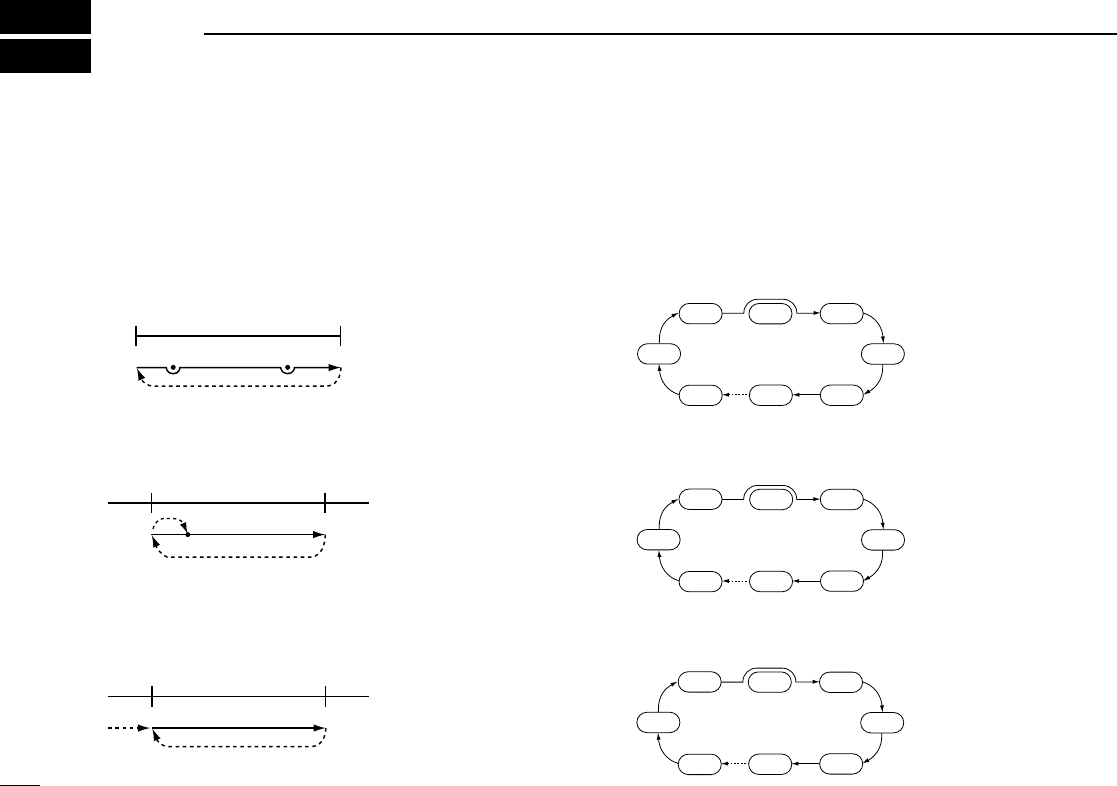
45
6SCAN OPERATION
■Scan types Up to 25 programmed scan ranges (0A/0B to 24A/24B), full
scan, band scan and memory bank scan provide scanning
versatility. Each scan can have skip channels programmed.
DVFO scans
FULL SCAN (p. 46)
Repeatedly scans all fre-
quencies over the entire re-
ceive range.
•Some frequency ranges
are restricted depending on
versions.
BAND SCAN (p. 46)
Repeatedly scans all fre-
quencies over the entire se-
lected band.
PROGRAMMED SCAN (p. 46)
Repeatedly scans between
two user-programmed fre-
quencies. Used for checking
for frequencies within a
specified range such as re-
peater output frequencies,
etc.
DMemory scans
MEMORY SCAN (p. 48)
Repeatedly scans all mem-
ory channels except skip
channels.
FULL BANK SCAN (p. 48)
Repeatedly scans memory
channels except skip chan-
nels within all memory banks
(i.e. memory channels,
A00–Y99).
MEMORY BANK SCAN (p. 48)
Repeatedly scans memory
channels except skip chan-
nels within a memory bank
(i.e. memory channels,
A00–A99).
CH
-
A00
CH
-
A01 CH
-
A02 CH
-
A03
CH
-
A04
CH
-
A05
CH
-
A06
CH
-
A99
SKIP
CH
-
A00
CH
-
A01 CH
-
A02 CH
-
B00
CH
-
C00
CH
-
D00
CH
-
E00
CH
-
Y00
SKIP
CH
-
000
CH
-
001 CH
-
002 CH
-
003
CH
-
004
CH-005
CH
-
006
CH
-
499
SKIP
Jump
Lower
scan edge
(0A–24A)
Upper
scan edge
(0B–24B)
Scan
Jump
Lower
band edge
Upper
band edge
Scan
Jump
Start
Lower
edge
Upper
edge
Scan
Jump
P SKIPP SKIP
IC-T90A_IM.qxd 02.5.28 01:13 PM Page 48 (1,1)

46
6
SCAN OPERATION
yy
SCAN OPERATION
■VFO scan
The following scans are available for the VFO scan.
FULL SCAN
Repeatedly scans all frequencies over the entire receive
range.
•Some frequency ranges are restricted depending on versions.
BAND SCAN
Repeatedly scans all frequencies over the entire selected
band.
PROGRAMMED SCAN
Repeatedly scans between two user-programmed frequen-
cies. Used for checking for frequencies within a specified
range such as repeater output frequencies, etc.
Skip frequencies are not scanned when the frequency skip
function is in use. (“P SKIP” appears)
If the same frequencies are programmed into a pair of
scan edges, programmed scan does not start.
For programmed scan, scan edges must be programmed
in advance. Program scan edges in the same manner of
programming a memory channel. (p. 37)
qSelect VFO mode with [VFO].
wPush [5 SKIP] for 1 sec. to toggle the frequency skip func-
tion ON or OFF.
•“P SKIP” appears when the frequency skip function is turned ON.
eSet the squelch level, if desired.
rWhile pushing [MODE SCAN], rotate [DIAL] to select the
desired scan range.
•“ALL” for full scan, “BAND” for band scan or “PROG 0–24” for
programmed scan.
tRelease [MODE SCAN] to start the scan.
•Decimal point flashes while scanning.
•“P SKIP” flashes when the frequency skip function is turned ON.
•To change the scanning direction, rotate [DIAL].
•If the pocket beep or DTCS beep function is activated, the trans-
ceiver automatically selects the tone squelch or DTCS squelch
function when a scan starts.
yTo stop the scan, push [VFO].
FM SKIPP
Full scan Band scan
Programmed scan Scanning example
Flashes while scanning.
IC-T90A_IM.qxd 02.5.28 01:13 PM Page 49 (1,1)
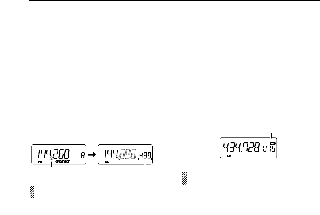
47
6SCAN OPERATION
■Frequency skip function
Unwanted frequencies can be skipped and programmed as
skip channels when full scan, band scan or programmed scan
is pausing.
qStart a VFO scan. (p. 46)
wWhile receiving an unwanted signal and scan pauses,
push [5 SKIP] for 1 sec. to program the received frequency
as a skip frequency.
•The transceiver emits 3 beeps and the scan resumes.
•Non-programmed memory channels (blank channels) are used
for skip frequency programming in reverse sequence.
•Do not release [5 SKIP] before 1 sec., otherwise, scan stops and
the transceiver enters frequency setting condition.
To scan the skip frequency after programming, cancel the
skip information or clear the memory channel. (p. 43)
■Skip channel setting
Memory channels can be set to be skipped for memory skip
scan. In addition, memory channels can be set to be skipped
for both memory skip scan and frequency skip scan. These
are useful to speed-up the scan interval.
qSelect memory mode with [MR].
wRotate [DIAL] to select memory channel to set the skip in-
formation.
ePush [5 SKIP] for 1 sec. one or more times to select con-
dition.
•“OFF” for no skipping of channels, “SKIP” for memory skip scan
or “P SKIP” for frequency skip scan and memory skip scan.
“P SCAN” setting is effective when the frequency skip func-
tion is turned ON. (p. 46)
FM SKIPP
Skip indication
FM SKIPP
FM SKIPP
Push [5 SKIP] for 1 sec. to program
the frequency as a skip frequency.
Blank channels are used in
reverse sequence.
Flashes while scanning.
When scan pauses.
IC-T90A_IM.qxd 02.5.28 01:13 PM Page 50 (1,1)
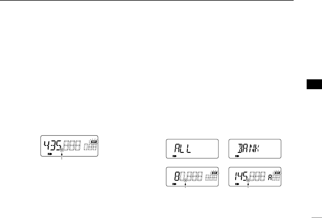
48
6
SCAN OPERATION
yy
SCAN OPERATION
■Memory scan
Memory scan repeatedly scans all memory channels except
skip channels.
qSelect memory mode with [MR].
•Pushing [MR] toggles the memory channel and memory bank in-
dications.
wSet the squelch level, if desired.
ePush [MODE SCAN] for 1 sec. to start the memory scan.
•Decimal point flashes while scanning.
•To change the scanning direction, rotate [DIAL].
•While receiving an unwanted signal and scan pauses, push [5
SKIP] for 1 sec. to set the received channel as a skip channel.
rTo stop the scan, push [VFO].
■Memory bank scan
Memory bank scan repeatedly scans memory channels ex-
cept skip channels within all memory banks or a memory
bank.
qSelect memory bank mode with [MR].
•Pushing [MR] toggles the memory channel and memory bank in-
dications.
•Program 2 or more memory channels to a memory bank in ad-
vance.
wSet the squelch level, if desired.
eFor the memory bank scan, push [BAND] to select the de-
sired memory bank.
rWhile pushing [MODE SCAN], rotate [DIAL] to select the
desired scan range.
•“ALL” for full bank scan or “BANK” for memory bank scan.
tRelease [MODE SCAN] to start the memory scan.
•Decimal point flashes while scanning.
•To change the scanning direction, rotate [DIAL].
yTo stop the scan, push [VFO].
FM SKIPP
FM SKIPPW
Scanning example Scanning example
Full bank scan Memory bank scan
Flashes while scanning.
Flashes while scanning.
FM SKIPP
Flashes while scanning.
IC-T90A_IM.qxd 02.5.28 01:13 PM Page 51 (1,1)

49
6SCAN OPERATION
■Scan notes
DSquelch setting
Scanning stops when the squelch opens. Make sure the
squelch is set to the threshold point or desired squelch level.
➥Rotate the tuning dial while pushing [SQL] to select auto-
matic squelch (AUTO) or a level (1–9) where the noise is
muted. (p. 22)
DTuning dial while scanning
➥Scan starts in the upward direction. To change the scan-
ning direction, rotate [DIAL] clockwise or counterclockwise.
➥Rotating [DIAL] while pausing a scan resumes the scan
manually.
DTuning step while scanning
Tuning steps while scanning becomes the selected tuning
step. Reset the tuning step before scanning, if necessary.
(p. 13)
DSkip function
Memory channels can be set to be skipped for memory skip
scan. In addition, memory channels can be set to be skipped
for both memory skip scan and frequency skip scan. These
are useful to speed-up the scan interval. (p. 48)
DWhen receiving a signal
The scan pauses according to the scan pause time (default:
10 sec.). It can be selected as a pause or timer scan
(2–20 sec.) in set mode. (p. 58)
The scan restarts after a signal disappears according to the
resume time (default: 2 sec.). It can be selected to 0–5 sec. or
‘hold’(indefinitely) in set mode. (p. 58)
DScan stop beep
A beep sounds when a scan stops to confirm the scan de-
tects a signal. This function can be turned ON or OFF in ex-
panded set mode 1. (p. 62)
DScan stop LED
The keypad backlighting flashes when a scan stops to con-
firm the scan detects a signal. This function can be turned ON
or OFF in expanded set mode 1. (p. 62)
DReceive indicator ON/OFF
The receive indicator can be turned ON or OFF in set mode.
(p. 59)
IC-T90A_IM.qxd 02.5.28 01:13 PM Page 52 (1,1)
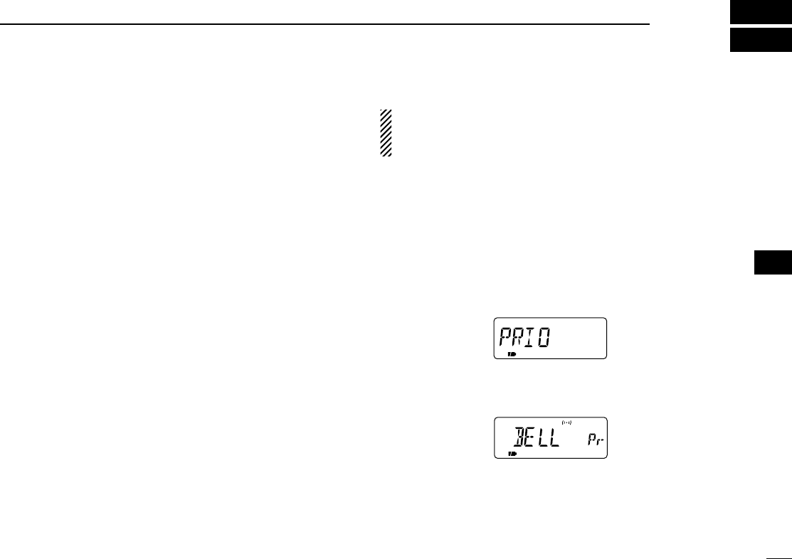
50
7
PRIORITY WATCH
■Priority watch types
Priority watch checks for signals on a frequency every 5 sec.
while operating on a VFO frequency or scanning. The trans-
ceiver has 6 priority watch types to suit your needs.
The watch resumes according to the selected scan resume
condition. See p. 58 for details.
MEMORY or CALL CHANNEL WATCH
While operating on a VFO frequency, priority watch checks
for a signal in the selected memory or call channel every 5
sec.
•A memory channel with skip information can be watched.
MEMORY SCAN WATCH
While operating on a VFO frequency, priority watch checks
for signals in each memory channel in sequence.
•The memory skip function is useful to speed up the scan.
VFO SCAN with MEMORY or CALL CHANNEL WATCH
While scanning in VFO mode, priority watch checks for sig-
nals in the selected memory or call channel every 5 sec.
VFO SCAN with MEMORY SCAN WATCH
While scanning in VFO mode, priority watch checks for sig-
nals in memory channels every 5 sec.
If the pocket beep function is activated, the transceiver au-
tomatically selects the tone squelch function when priority
watch starts.
■Priority alert
You can be alerted with beeps and a flashing “S,” when a
priority watch detects a signal on the watching frequency.
qPush [8 SET] for 1 sec. to enter set mode.
wRotate [DIAL] until “PRIO” appears.
ePush [8 SET] to select the priority watch item.
rRotate [DIAL] to select the priority alert item. (“BELL”)
tPush [VFO] to exit set mode and start the priority watch.
uu
PRIORITY WATCH
IC-T90A_IM.qxd 02.5.28 01:13 PM Page 53 (1,1)
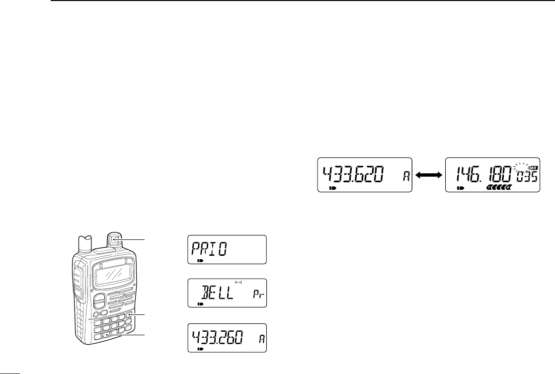
51
7PRIORITY WATCH
■Priority watch operation
DMemory channel watch
While operating on a VFO frequency, priority watch checks
for a signal in the selected memory channel every 5 sec.
•A memory channel with skip information can be watched.
qSelect VFO mode; then, set an operating frequency.
wSelect the desired memory channel.
ePush [8 SET] for 1 sec. to enter set mode.
rRotate [DIAL] until “PRIO” appears.
tPush [8 SET] to select the priority watch item.
yRotate [DIAL] to select the priority watch (“ON”) or priority
watch with alert (“BELL”).
uPush [VFO] to exit set mode and start the priority watch.
•The transceiver checks the memory channel frequency every
5 sec.
•The watch resumes according to the selected scan resume con-
dition. (p. 58)
iPush [VFO] while the display shows the VFO frequency to
stop the watch.
PRIO
FM
PRIO
FM SKIPP
Checks for a signal in the selected
memory channel every 5 sec.
While operating on a VFO
frequency
The watch stops on the selected
channel when a signal is received.
FM
PRIO
SKIPP
[VFO]
[DIAL]
[8 SET]
Priority watch item
Priority watch with alert
Push [VFO] to start.
IC-T90A_IM.qxd 02.5.28 01:13 PM Page 54 (1,1)
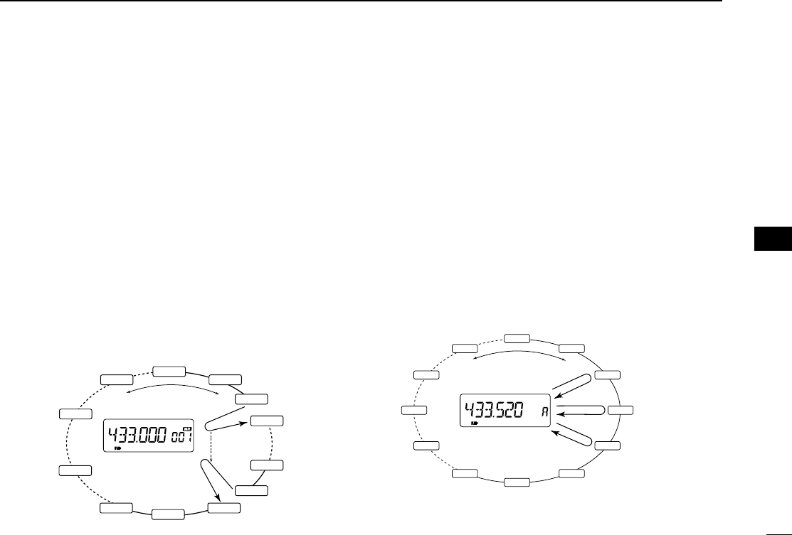
52
7
PRIORITY WATCH
DVFO scan with memory channel watch
While scanning in VFO mode, priority watch checks for sig-
nals in the selected memory channel every 5 sec.
•A memory channel with skip information can be watched.
qSelect the desired memory channel to be watched.
wSelect VFO mode.
ePush [MODE SCAN] for 1 sec. to start a VFO scan. (full
scan, band scan or programmed scan)
rPush [8 SET] for 1 sec. to enter set mode.
tRotate [DIAL] until “PRIO” appears.
yPush [8 SET] to select the priority watch item.
uRotate [DIAL] to select the priority watch (“ON”) or priority
watch with alert (“BELL”).
iPush [VFO] to exit set mode and start the priority watch.
oPush [VFO] while the display shows the VFO frequency to
stop the VFO scan and priority watch.
DMemory scan watch
While operating on a VFO frequency, priority watch checks
for a signal in memory channels every 5 sec.
qSelect VFO mode; then, set an operating frequency.
wSelect memory mode.
ePush [MODE SCAN] for 1 sec. to start a memory scan.
rPush [8 SET] for 1 sec. to enter set mode.
tRotate [DIAL] until “PRIO” appears.
yPush [8 SET] to select the priority watch item.
uRotate [DIAL] to select the priority watch (“ON”) or priority
watch with alert (“BELL”).
iPush [VFO] to exit set mode and start the priority watch.
oPush [VFO] while the display shows the VFO frequency to
stop the watch.
CH-000
CH-499
CH-400
CH-300
CH-200
CH-100
CH-006
CH-005
CH-004
CH-003
CH-002
CH-001
Memory scan
VFO frequency 5 sec.
Pauses when a signal
is received in Mch.
Watches Mch while
operating on VFO.
FM SKIPP
PRIO
VFO scan
Memory channel
5 sec.
Watches Mch while
VFO scanning.
Pauses when a signal
is received in Mch.
FM
PRIO
145.100
145.120
145.140
145.200
145.220
145.240
145.260
51.000
850.000
433.500
433.000
145.280
uu
PRIORITY WATCH
IC-T90A_IM.qxd 02.5.28 01:13 PM Page 55 (1,1)

53
7PRIORITY WATCH
DVFO scan with memory scan watch
While scanning in VFO mode, priority watch checks for sig-
nals in memory channels every 5 sec.
qSelect memory mode.
wPush [MODE SCAN] for 1 sec. to start a memory scan.
•Start the memory scan first, otherwise, memory scan watch does
not start.
ePush [8 SET] for 1 sec. to enter set mode.
rRotate [DIAL] until “PRIO” appears.
tPush [8 SET] to select the priority watch item.
yRotate [DIAL] to select the priority watch (“ON”) or priority
watch with alert (“BELL”).
uPush [VFO] to exit set mode and start the memory scan
watch.
iPush [MODE SCAN] for 1 sec. to start a VFO scan. (full
scan, band scan or programmed scan)
•VFO scan with memory scan watch is now activated.
•The scan or watch pauses when a signal is received on a VFO
frequency or watching memory channels.
oPush [VFO] while the display shows the VFO frequency to
stop the VFO scan and priority watch.
DCall channel watch
While operating on a VFO frequency, priority watch checks
for a signal in the selected call channel every 5 sec.
qSelect VFO mode; then, set an operating frequency.
wPush [CALL/TV] to select call channel mode.
eRotate [DIAL] to select the desired call channel.
rPush [8 SET] for 1 sec. to enter set mode.
tRotate [DIAL] until “PRIO” appears.
yPush [8 SET] to select the priority watch item.
uRotate [DIAL] to select the priority watch (“ON”) or priority
watch with alert (“BELL”).
iPush [VFO] to exit set mode and start the priority watch.
oPush [VFO] while the display shows the VFO frequency to
stop the watch.
FM
PRIO
SKIPPFM
PRIO
Checks for a signal in the selected
call channel every 5 sec.
While operating on a VFO
frequency
The watch stops on the selected
channel when a signal is received.
IC-T90A_IM.qxd 02.5.28 01:13 PM Page 56 (1,1)

54
7
PRIORITY WATCH
DVFO scan with call channel watch
While scanning in VFO mode, priority watch checks for sig-
nals in the selected call channel every 5 sec.
qSelect VFO mode.
wPush [CALL/TV] to select call channel mode.
eRotate [DIAL] to select the desired call channel.
rPush [8 SET] for 1 sec. to enter set mode.
tRotate [DIAL] until “PRIO” appears.
yPush [8 SET] to select the priority watch item.
uRotate [DIAL] to select the priority watch (“ON”) or priority
watch with alert (“BELL”).
iPush [VFO] to exit set mode and start the priority watch.
oPush [MODE SCAN] for 1 sec. to start a VFO scan. (full
scan, band scan or programmed scan)
!0 Push [VFO] while the display shows the VFO frequency to
stop the VFO scan and priority watch.
VFO scan
Call channel
5 sec.
Watches call Ch
while VFO scanning.
Pauses when a signal
is received in call Ch.
PRIO
FM
145.100
145.120
145.140
145.200
145.220
145.240
145.260
51.000
850.000
433.500
433.000
145.280
uu
PRIORITY WATCH
IC-T90A_IM.qxd 02.5.28 01:13 PM Page 57 (1,1)
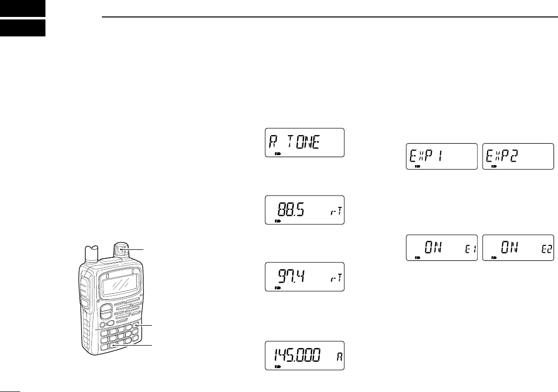
55
8SET MODE
■Set mode
Set mode is used for programming in-
frequently changed values or conditions
of functions.
In addition, this transceiver has 2 ex-
panded set modes which are used for
programming more infrequently
changed values or conditions of func-
tions. When turning the expanded set
modes OFF, only half of the set mode
items are displayed for simple opera-
tion.
DEntering set mode
qPush [8 SET] for 1 sec. to enter set
mode.
wRotate [DIAL] until the desired item
appears.
ePush [8 SET] to select the set mode
item.
rRotate [DIAL] to select a set mode
item.
tPush [VFO] to exit set mode or push
[8 SET] then rotate [DIAL] to select
another set mode item.
DExpanded set mode
ON/OFF
qPush [8 SET] for 1 sec. to enter set
mode.
wRotate [DIAL] until “EXP1” or “EXP2”
appears.
ePush [8 SET] to select an expanded
set mode.
rRotate [DIAL] to turn the expanded
set mode ON or OFF.
tPush [8 SET] then rotate [DIAL] to
select a set mode item in the ex-
panded set mode, or push [VFO] to
exit set mode.
SKIPP
FM
[VFO]
[8 SET]
[DIAL]
IC-T90A_IM.qxd 02.5.28 01:13 PM Page 58 (1,1)

56
8
SET MODE
■Set mode items
Set mode is used for programming infrequently changed val-
ues or conditions of functions.
General set mode
R TONE Repeater tone (p. 57)
C TONE Tone squelch/pocket beep frequency (p. 57)
CODE DTCS squelch/beep code (p. 57)
OFFSET Offset frequency (p. 57)
RESUME Scan resume time (p. 58)
PAUSE Scan pause timer (p. 58)
PRIO Priority watch (p. 58)
BEEP LV Beep tone level (p. 58)
BEEP Beep tone (p. 59)
LIGHT Display backlighting (p. 59)
BUSY Busy LED (p. 59)
AP OFF Auto power-off (p. 59)
P SAVE Power save (p. 60)
MONI Monitor switch action (p. 60)
SPEED Dial speed acceleration (p. 60)
AUTORP Auto repeater (p. 61)
DTMF DTMF speed (p. 61)
MIC Optional HM-75A functions (p. 61)
WX ALT Weather alert function (p. 62)
EXP1 Expanded set mode 1 (upper right)
EXP2 Expanded set mode 2 (lower right)
EXP1 (Expanded set mode 1)
STOP B Scan stop beep (p. 62)
STOP L Scan stop LED (p. 62)
LIGHT P Backlighting position (p. 62)
COLOR Backlighting color (p. 63)
EDGE B Band edge beep (p. 63)
AP ON Auto power-on (p. 63)
LOCK Key lock effect (p. 63)
PTT LK PTT lock (p. 64)
CONT Contrast (p. 64)
OPN.MSG Opening message (p. 64)
Appears when expanded set mode 1 is ON.
EXP2 (Expanded set mode 2)
DTCS P DTCS phase mode (p. 65)
LK OUT Busy lock out (p. 65)
TOT Time-out timer (p. 65)
ACTIVE Active band (p. 65)
SPLIT Split operation (p. 66)
NARROW FM narrow deviation (p. 66)
MC SYN Morse code synthesizer (p. 66)
KY SPD Morse code keying speed (p. 66)
Appears when expanded set mode 2 is ON.
ii
SET MODE
IC-T90A_IM.qxd 02.5.28 01:13 PM Page 59 (1,1)
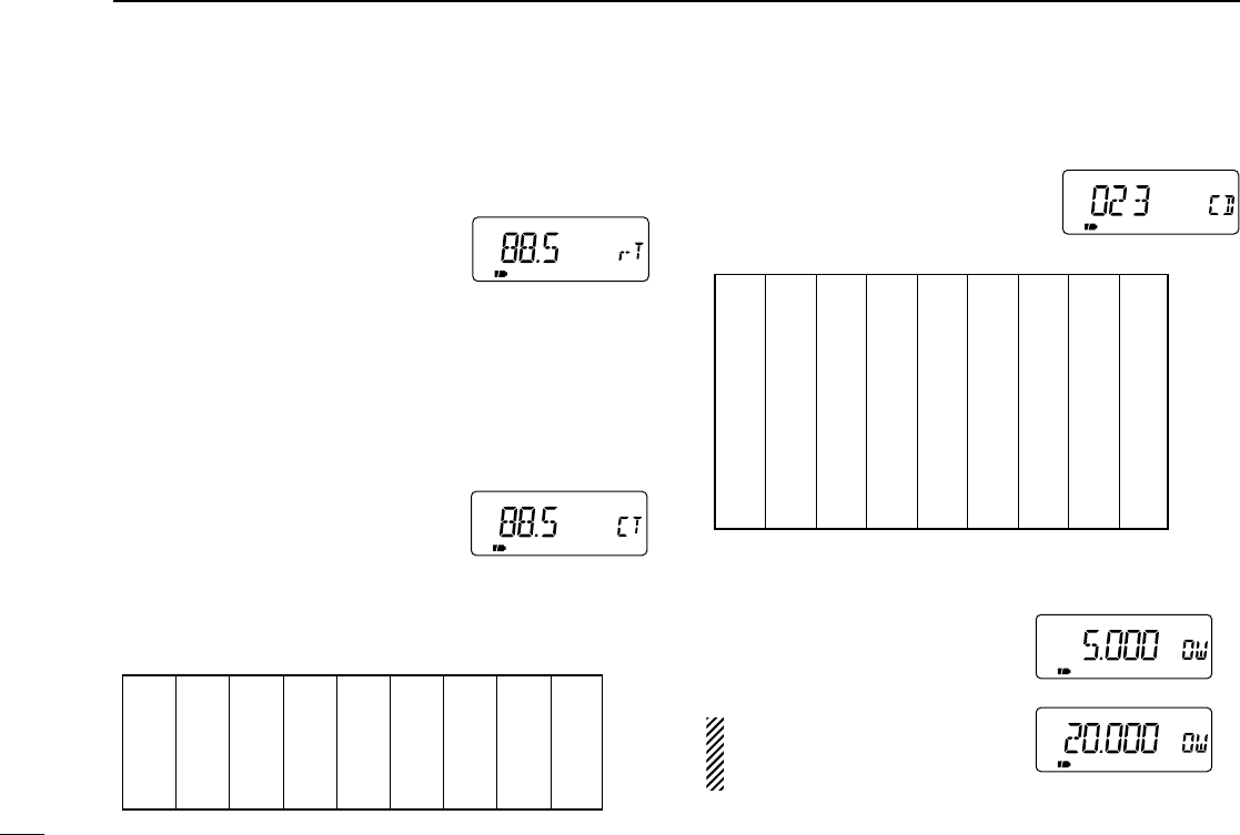
57
8SET MODE
•Repeater tone (R TONE)
Selects tone encoder frequency for accessing a repeater, etc.
from one of 50 available tone frequencies.
•67.0–254.1 Hz (50 tones):
88.5 Hz (default)
•Tone squelch frequency (C TONE)
Selects tone squelch or pocket beep frequency from one of
50 available tone frequencies.
•67.0–254.1 Hz (50 tones):
88.5 Hz (default)
[Repeater/Tone squelch tone table]
•DTCS squelch code (CODE)
Selects DTCS squelch code from one of 104 available codes.
•023–754 (104 codes):
023 (default)
[DTCS code table]
•Offset frequency (OFFSET)
Sets the offset frequency for duplex
(repeater) operation within
0–159.995 MHz range.
The offset frequency changes
according to the selected tuning
steps. (p. 18)
023
025
026
031
032
036
043
047
051
053
054
065
071
072
073
074
114
115
116
122
125
131
132
134
143
145
152
155
156
162
165
172
174
205
212
223
225
226
243
244
245
246
251
252
255
261
263
265
266
271
274
306
311
315
325
331
332
343
346
351
356
364
365
371
411
412
413
423
431
432
445
446
452
454
455
462
464
465
466
503
506
516
523
526
532
546
565
606
612
624
627
631
632
654
662
664
703
712
723
731
732
734
743
754
67.0
69.3
71.9
74.4
77.0
79.7
82.5
85.4
88.5
91.5
94.8
97.4
100.0
103.5
107.2
110.9
114.8
118.8
123.0
127.3
131.8
136.5
141.3
146.2
151.4
156.7
159.8
162.2
165.5
167.9
171.3
173.8
177.3
179.9
183.5
186.2
189.9
192.8
196.6
199.5
203.5
206.5
210.7
218.1
225.7
229.1
233.6
241.8
250.3
254.1
IC-T90A_IM.qxd 02.5.28 01:13 PM Page 60 (1,1)
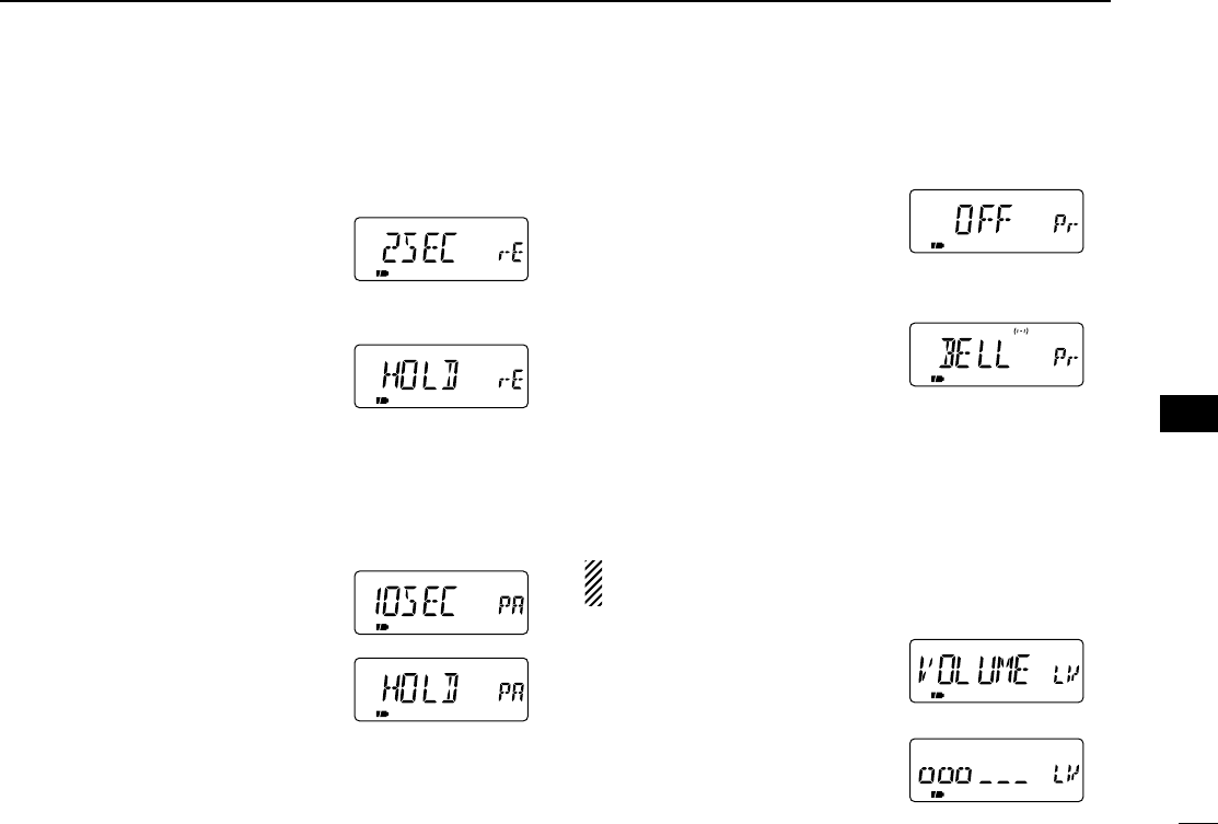
58
8
SET MODE
•Scan resume time (RESUME)
Selects the scan resume time from pausing on a frequency
after the received signal disappears.
•0 scan resumes when a received
signal disappears.
•1–5 scan pauses 1–5 sec. after a
received signal disappears.
(default: 2 sec.)
•Hold scan pauses on a received sig-
nal even if it disappears. Rotate
the tuning dial to resume manu-
ally.
•Scan pause timer (PAUSE)
Selects the scan pause time. When receiving signals, the
scan pauses according to the scan pause time.
•2–20 scan pauses for 2–20 sec. on
a received signal in 2 sec.
steps. (default: 10 sec.)
•Hold scan pauses on a received
signal until it disappears. Ro-
tate the tuning dial to resume
manually.
•Priority watch (PRIO)
Activates priority watch or priority watch with alert (BELL).
•OFF The priority watch is
turned OFF. (default)
•ON The transceiver checks
the memory channel fre-
quency every 5 sec.
•BELL The transceiver checks
the memory channel fre-
quency every 5 sec. You
can be alerted with beeps
and a flashing “S”.
•Beep tone level (BEEP LV)
Adjusts confirmation beep output level to the desired level
within 32 levels or to the related level with volume.
The confirmation beep (next item) must be turned on to
have a beep tone.
•VOLUME The beep tone volume
level is linked with the
receive volume level.
(default)
•- - - - - - The beep tone volume
ooo ooo level can be set in 32
steps.
ii
SET MODE
IC-T90A_IM.qxd 02.5.28 01:13 PM Page 61 (1,1)
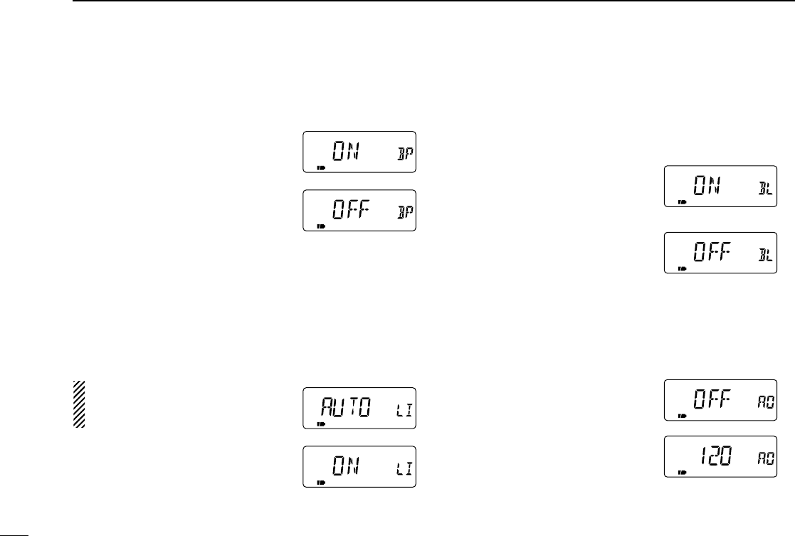
59
8SET MODE
•Beep tone (BEEP)
Turns confirmation beep ON or OFF.
•ON The confirmation beep is turned
ON. (default)
•OFF The confirmation beep is turned
OFF.
•Display backlighting (LIGHT)
The transceiver has display backlighting with a 5 sec. timer
for nighttime operation. The display backlighting can be
turned ON continuously or turned OFF, if desired.
“AUTO” setting turns the backlight-
ing ON while operating with an ex-
ternal DC power. (10–11.5 V DC)
•AUTO The display backlighting is
ON with a 5 sec. timer. (de-
fault)
•ON The display backlighting is turned ON.
•OFF The display backlighting is turned OFF.
•Busy LED (BUSY)
The TX/RX indicator lights green while receiving a signal or
when the squelch is open. This indication can be turned OFF
to conserve the battery power, if desired.
•ON The indicator lights green
while receiving a signal or
when the squelch is open.
(default)
•OFF The indicator does not func-
tion even if a signal is re-
ceived.
•Auto power-off (AP OFF)
The transceiver can be set to automatically turn OFF after a
specified period with beep in which no switch is pushed.
120 min., 90 min., 60 min., 30 min.
and OFF can be specified. The
specified period is retained even
when the transceiver is turned OFF
by the auto power-off function. To
cancel the function, select “OFF” in
this set mode.
IC-T90A_IM.qxd 02.5.28 01:13 PM Page 62 (1,1)
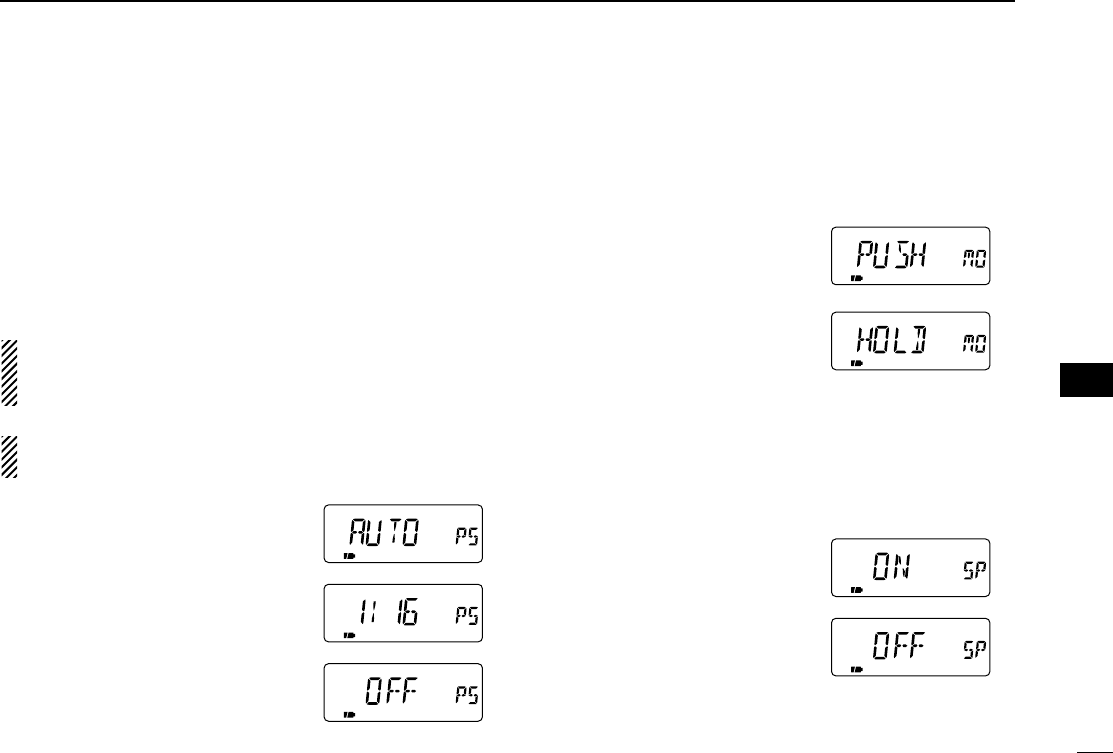
60
8
SET MODE
•Power save (P SAVE)
The power save function reduces the current drain to con-
serve battery power. This item sets the power save duty
cycle—the ratio of receive circuit on to receive circuit off while
standing by. The duty cycle can be set to automatic (default),
1:1, 1:4, 1:8, 1:16 or OFF.
“AUTO” selects “1:4” duty ratio when receiving no signal for 5
sec., then “1:8” 60 sec. after that.
When “AUTO” is selected, the power save automatically
turns OFF while operating with an external DC power
(10–11.5 V DC)
For packet operation, the power save should be turned
OFF to receive reliable packet data.
•Monitor switch action (MONI)
The monitor switch can be set as a ‘sticky’switch. When set
to the sticky condition, each push of [SQL] toggles the moni-
tor function on and off.
•PUSH Set the monitor switch to
normal. (default)
•HOLD Set the monitor switch to
sticky switch.
•Dial speed acceleration (SPEED)
The dial speed acceleration automatically speeds up the tun-
ing dial speed when rotating the [DIAL] rapidly.
•ON The dial speed acceleration
is turned ON. (default)
•OFF The dial speed acceleration
is turned OFF.
ii
SET MODE
IC-T90A_IM.qxd 02.5.28 01:13 PM Page 63 (1,1)
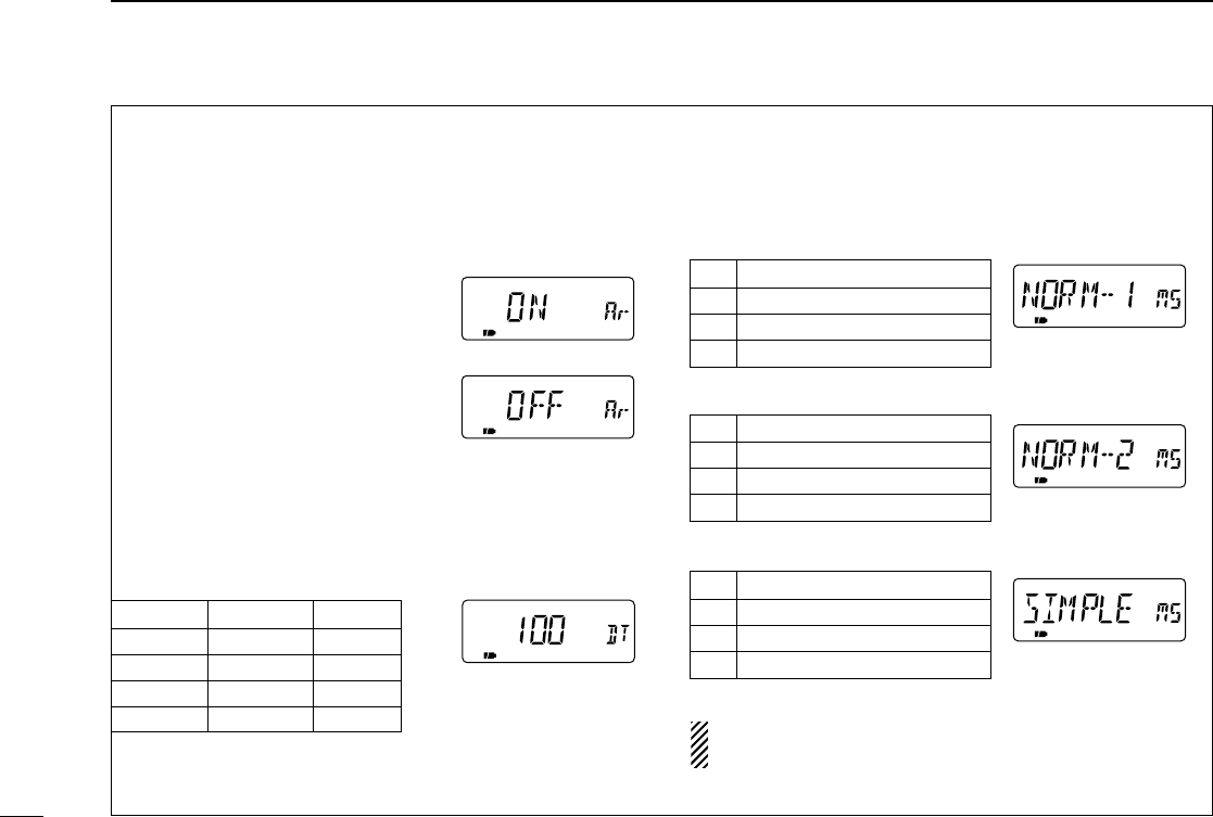
•Auto repeater (AUTO RP)
The auto repeater function automatically turns ON or OFF the
duplex operation with specified shift direction and tone en-
coder, when the operating frequency falls within or outside of
the general repeater output frequency range.
U.S.A. version:
•ONLY
Activates duplex only. (default)
•TONE Activates duplex and tone.
•OFF Deactivates the function.
Korea version:
•ON Activates duplex and tone. (de-
fault)
•OFF Deactivates the function.
•DTMF speed (DTMF)
The rate at which DTMF memories send individual DTMF
characters can be set to accommodate operating needs.
DISPLAY INTERVAL SPEED
100 100 msec. 5.0 cps
200 200 msec. 2.5 cps
300 300 msec. 1.6 cps
500 500 msec. 1.0 cps
cps=characters/sec.
•Optional HM-75A functions MIC
Microphone simple mode is used to change the function as-
signments for switches on the optional HM-75A REMOTE CON-
TROL MICROPHONE.
•NORM-1: (default)
[A] Selects band.
[B] Toggles VFO and memory.
[Y] [UP]
[Z] [DOWN]
•NORM-2:
[A] Toggles monitor function.
[B] Toggles VFO and memory.
[Y] [UP]
[Z] [DOWN]
•SIMPLE:
[A] Toggles monitor function.
[B] Selects call channel C0.
[Y] Selects memory Ch 000.
[Z] Selects memory Ch 001.
VFO mode cannot be selected via the microphone when
SIMPLE mode is selected.
61
8SET MODE
IC-T90A_IM.qxd 02.5.28 01:13 PM Page 64 (1,1)
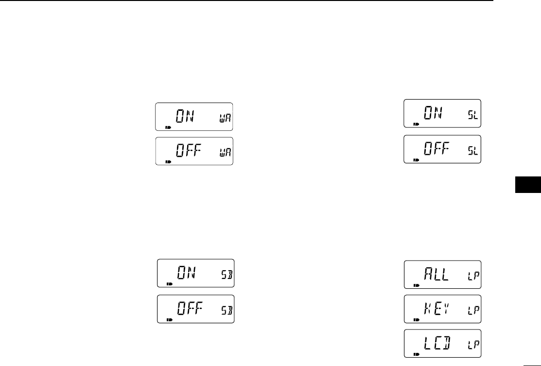
62
8
SET MODE
•Wether Alert (WX ALT)
(USA version only)
Turns wether alert function ON or OFF.
•ON The WX alert beep sounds
when a alert signal is
received.
•OFF The WX alert beep does not
sound. (default)
•Scan stop beep (STOP B)
Turns scan stop beep ON or OFF.
•Turn the expanded set mode 1 ON in advance.
•ON The scan stop beep sounds
when a scan is stopped.
•OFF The scan stop beep does not
sound even when a scan is
stopped. (default)
•Scan stop LED (STOP L)
Turns scan stop LED ON or OFF.
•Turn the expanded set mode 1 ON in advance.
•ON The keypad backlighting
flashes in green and orange
when a scan is stopped.
•OFF The keypad backlighting
does not flash even when a
scan is stopped. (default)
•Backlighting position (LIGHT P)
Selects the lighting area from keypad only, function display
only and both keypad and function display.
•Turn the expanded set mode 1 ON in advance.
•ALL Lighting area is both keypad
and function display. (de-
fault)
•KEY Lighting area is keypad only.
•LCD Lighting area is function dis-
play only.
ii
SET MODE
IC-T90A_IM.qxd 02.5.28 01:13 PM Page 65 (1,1)
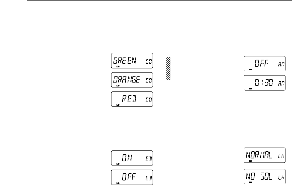
63
8SET MODE
•Backlighting color (COLOR)
Selects backlighting color between green, orange or red.
•Turn the expanded set mode 1 ON in advance.
•GREEN Green backlighting color.
(default)
•ORANGE Orange backlighting color.
•RED Red backlighting color.
•Band edge beep (EDGE B)
Turns band edge beep ON or OFF. The band edge beep
sounds when the operating frequency changes across the
band edge.
•Turn the expanded set mode 1 ON in advance.
•ON The band edge beep is turned
ON.
•OFF The band edge beep is turned
OFF. (default)
•Auto power ON (AP ON)
Turns the transceiver power ON after 30 min. to 24 hrs. in 30
min. steps.
•Turn the expanded set mode 1 ON in advance.
When operating with battery
pack or case and the battery is
exhausted, auto power-on does
not function.
•Key lock effect (LOCK)
While the lock function is ON, [PWR], [PTT], [SQL], [Y]/[Z]
and [CALL/TV LOCK] can still be accessed. Accessible
switches can be set to 1 of 4 groups.
•Turn the expanded set mode 1 ON in advance.
•NORMAL [PWR], [PTT], [SQL]
and [Y]/[Z] are acces-
sible.
•NO SQL [PWR], [PTT] and
[SQL] are accessible.
•NO VOL [PWR], [PTT] and
[Y]/[Z] are accessible.
•ALL [PWR] and [PTT] are accessible.
IC-T90A_IM.qxd 02.5.28 01:13 PM Page 66 (1,1)
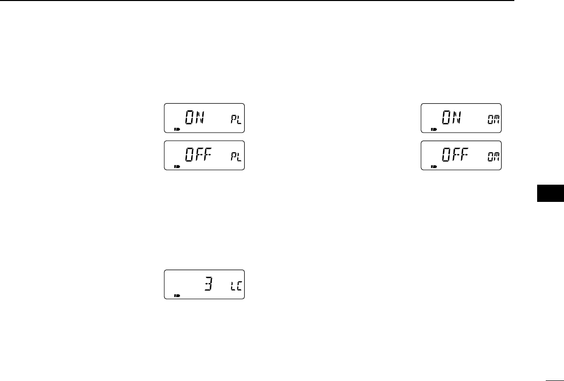
64
8
SET MODE
•PTT lock (PTT LK)
Turns PTT lock ON or OFF.
•Turn the expanded set mode 1 ON in advance.
•ON The PTT lock is turned ON.
•OFF The PTT lock is turned OFF.
(default)
•LCD contrast (CONT)
The contrast of the LCD can be adjusted from 4 levels.
•Turn the expanded set mode 1 ON in advance.
•1 (low contrast) – 4 (high contrast)
3 (default)
•Opening message (OPN.MSG)
Turns opening message ON or OFF.
•Turn the expanded set mode 1 ON in advance.
•ON Displays the opening mes-
sage at power ON. (default)
•OFF Does not display the open-
ing message at power ON.
ii
SET MODE
IC-T90A_IM.qxd 02.5.28 01:13 PM Page 67 (1,1)
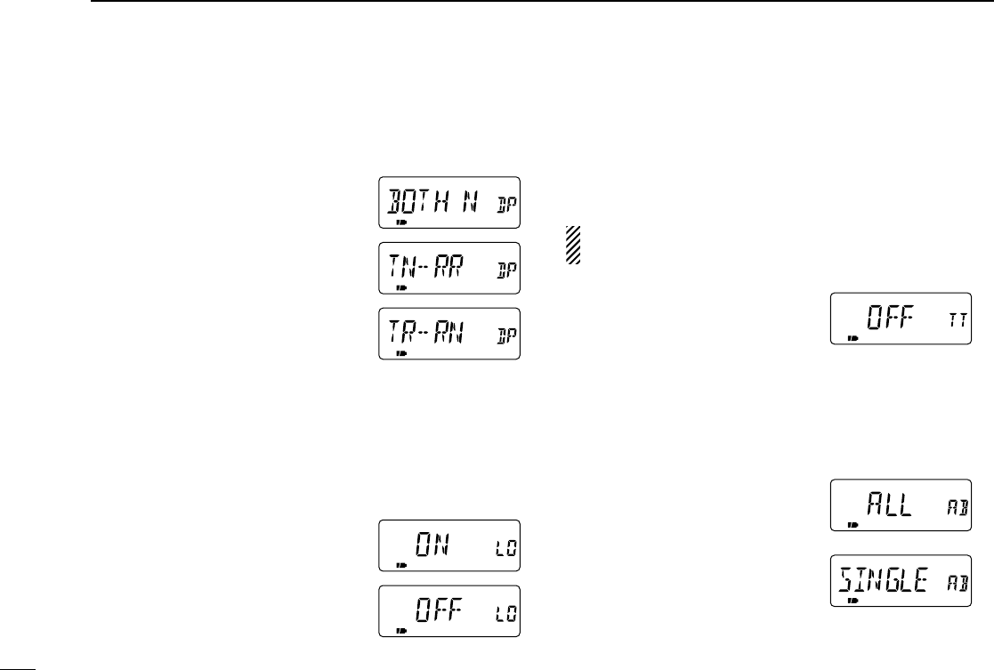
65
8SET MODE
•DTCS phase mode (DTCS P)
Selects DTCS phase mode.
•Turn the expanded set mode 2 ON in advance.
•BOTH N Normal phases are used for
both Tx and Rx. (default)
•TN-RR Normal phase is used for
Tx; Reverse phase for Rx.
•TR-RN Reverse phase is used for
Tx; Normal phase for Rx.
•BOTH R Reverse phases are used
for both Tx and Rx.
•Busy lock out (LK OUT)
Turns the busy lockout function ON and OFF. This function
inhibits transmission while receiving a signal or when the
squelch is open.
•Turn the expanded set mode 2 ON in advance.
•ON The busy lockout is turned ON.
•OFF The busy lockout is turned
OFF. (default)
•Time-out timer (TOT)
To prevent accidental prolonged transmission, etc., the trans-
ceiver has a time-out timer. This timer cuts a transmission
OFF after 1, 3, 5 or 10 min. of continuous transmission. This
timer can be cancelled.
•Turn the expanded set mode 2 ON in advance.
Approx. 10 sec. before the time-out timer is activated, the
transceiver emits a beep tone as a warning.
•OFF The time-out timer is turned
OFF. (default)
•1–10 The transmission is cut OFF
after the set period elapses.
•Active band (ACTIVE)
Allows continuous frequency selection of the operating fre-
quency across all bands.
•ALL The operating frequency
can be selected continu-
ously. (default)
•SINGLE The operating frequency
can be selected within
the current band. Push
[BAND] for band selec-
tion in this case.
IC-T90A_IM.qxd 02.5.28 01:13 PM Page 68 (1,1)
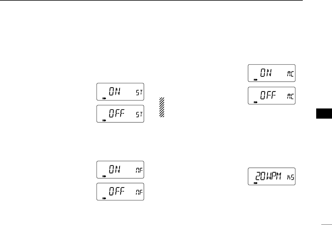
66
8
SET MODE
•Split operation (SPLIT)
Turns the split operation ON or OFF. Split frequency opera-
tion allows you to transmit and receive on two different fre-
quencies. Split frequency operation uses 2 frequencies, one
in VFO A and the other in VFO B.
•Turn the expanded set mode 2 ON in advance.
•ON The split operation is turned
ON. ‘SPA’appears for VFO A;
‘SPB’appears for VFO B.
•OFF The split operation is turned
OFF. (default)
•FM narrow deviation (NARROW)
Selects the maximum FM deviation for normal or narrow FM
mode on transmit mode.
•ON Selects the narrow FM devia-
tion for FM mode.
•OFF Selects the normal FM devia-
tion for FM mode. (default)
•Morse code synthesizer (MC SYN)
The transceiver announces the operating frequency or TV
channel number in Morse code.
•Turn the expanded set mode 2 ON in advance.
•ON The Morse code synthesizer
is turned ON.
•OFF The Morse code synthesizer
is turned OFF. (default)
Turning power ON while pushing
[CALL/TV] also toggles the
Morse code synthesizer ON or OFF.
•Morse code keying speed (KY SPD)
The keying speed of the Morse code synthesizer can be ad-
justed within 10 to 25 WPM for your convenience.
•Turn the expanded set mode 2 ON in advance.
•10–25 WPM in 5 WPM steps
20 WPM (default)
ii
SET MODE
IC-T90A_IM.qxd 02.5.28 01:13 PM Page 69 (1,1)
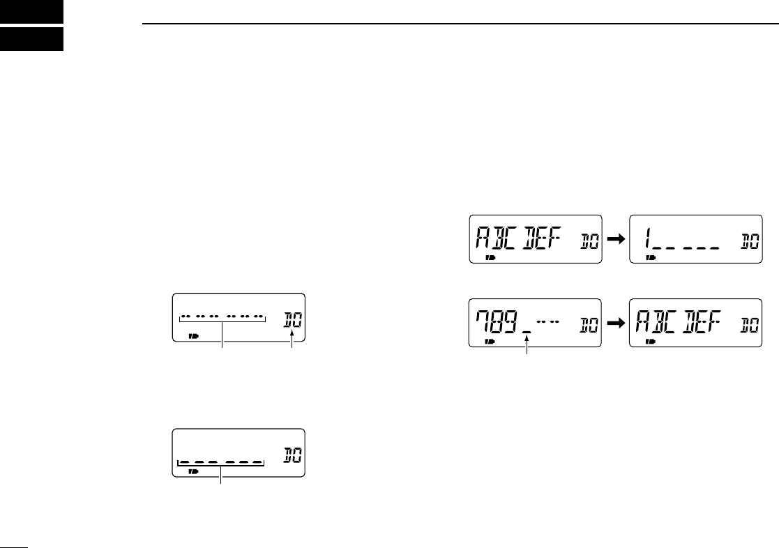
67
9OTHER FUNCTIONS
■Programming a DTMF code
DTMF codes are used for autopatching, accessing repeaters,
controlling other equipment, etc. The transceiver has 10
DTMF memory channels (D0–D9) for storage of often-used
DTMF codes of up to 16 digits.
qPush [• DTMF.M] for 1 sec. to enter DTMF memory.
wRotate [DIAL] to select the desired DTMF memory chan-
nel.
•“T-CALL” appears when a 1750 Hz tone burst signal is selected.
(p. 29)
ePush [• DTMF.M] for 1 sec. to enter programming mode.
•Previously programmed DTMF code is cleared.
rPush the desired keys to input the characters.
•[VFO] inputs “A,”[MR] inputs “B,”[CALL/TV] inputs “C,”[BAND]
inputs “D,” [•] inputs “M” (E) and [MODE] inputs “F” (#).
•Up to 16 digits can be programmed.
tRepeat runtil the desired code is input.
yPush [SQL] or [PTT] to program the DTMF code and exit
programming mode.
•Entering 16the digit automatically exits the programming mode.
Next display appears when
7th digit is input.
The display returns to 1st display
when 16th digit is input.
Programming mode
DTMF memory
channel
Blank channel
indication
IC-T90A_IM.qxd 02.5.28 01:13 PM Page 70 (1,1)
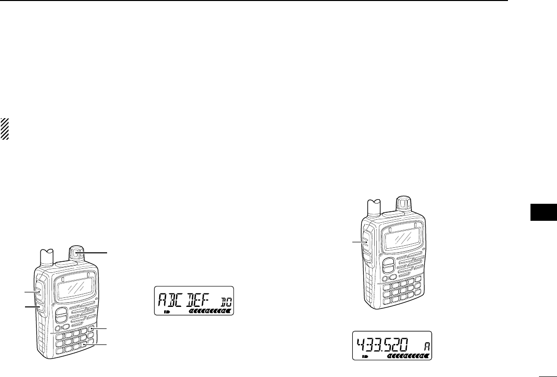
68
9
OTHER FUNCTIONS
■Transmitting a DTMF code
DTransmitting from DTMF memory
The selected DTMF code is transmitted at each push of the
[SQL] switch while transmitting.
The rate at which DTMF memories send individual DTMF
characters can be set in set mode. (p. 56)
qSet the desired frequency.
wPush [• DTMF.M] for 1 sec. to enter DTMF memory.
eRotate [DIAL] to select the desired DTMF memory chan-
nel.
rPush [VFO] to exit DTMF memory.
tWhile pushing [PTT], push [SQL] to transmit the selected
DTMF code.
DTransmitting a DTMF code directly
DTMF code can be transmitted via keypad directly while
transmitting.
qSet the desired frequency.
wWhile pushing [PTT], push the desired keys to transmit the
DTMF code.
•[VFO] transmits “A,”[MR] transmits “B,”[CALL/TV] transmits “C,”
[BAND] transmits “D,” [•] transmits “E” (M) and [MODE] transmits
“F” (#).
FM SKIPP
[PTT]
DTMF code is not displayed.
[SQL]
[PTT]
[• DTMF.M]
[DIAL]
[VFO]
DTMF code is displayed
6 digits at a time.
oo
OTHER FUNCTIONS
IC-T90A_IM.qxd 02.5.28 01:13 PM Page 71 (1,1)
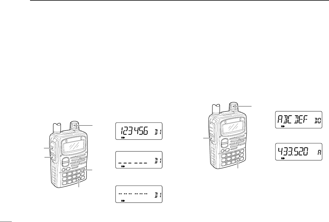
69
9OTHER FUNCTIONS
■Clearing a DTMF memory
An unwanted DTMF memory can be cleared (erased).
qPush [• DTMF.M] for 1 sec. to enter DTMF memory mode.
wRotate [DIAL] to select the desired DTMF memory chan-
nel to be cleared.
ePush [• DTMF.M] for 1 sec. to enter programming mode
and clear the selected DTMF memory channel.
•The DTMF memory channel is cleared.
rPush [SQL] or [PTT] to exit programming mode.
■Confirming a DTMF memory
The DTMF memory can be confirmed with DTMF tone.
qPush [• DTMF.M] for 1 sec. to enter DTMF memory mode.
wRotate [DIAL] to select the desired DTMF memory chan-
nel.
ePush [SQL] to confirm the DTMF memory contents.
•The display returns to frequency indication after confirmation.
FM SKIPP
[SQL]
[• DTMF.M]
[DIAL] DTMF code is displayed
6 digits at a time.
The display returns to
frequency indication.
[SQL]
[PTT]
[• DTMF.M]
[DIAL]
[VFO]
Select DTMF memory
to be cleared.
DTMF programming mode
The DTMF memory
becomes blank.
IC-T90A_IM.qxd 02.5.28 01:13 PM Page 72 (1,1)
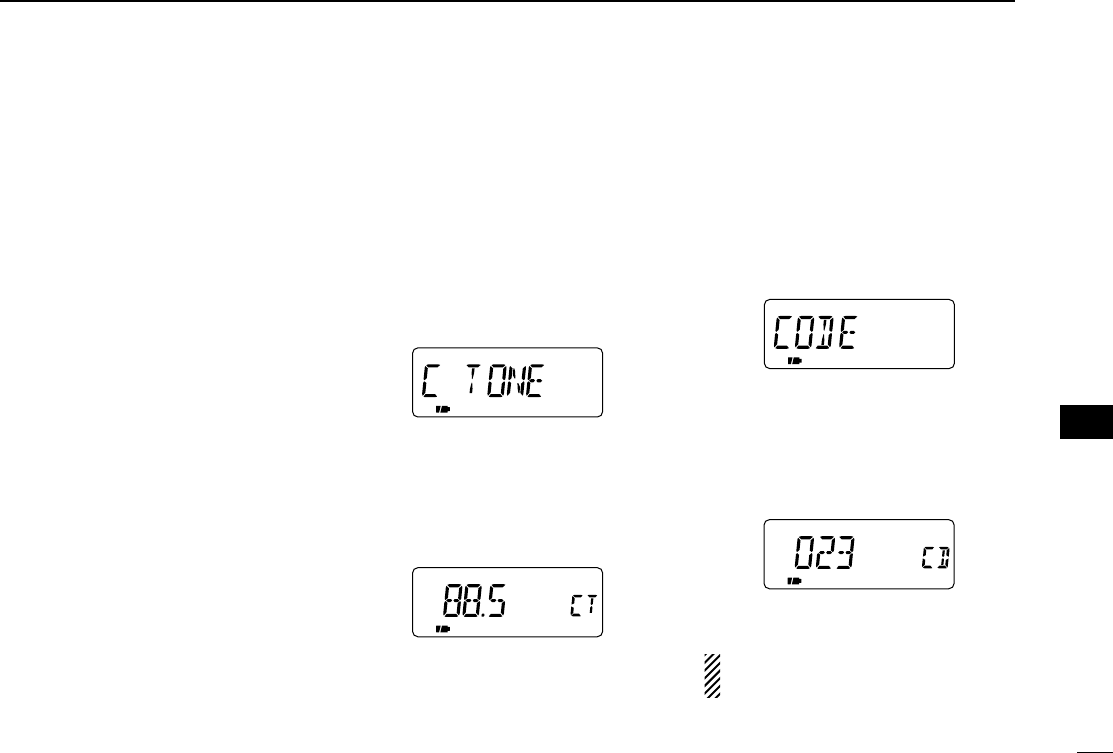
70
9
OTHER FUNCTIONS
•Subaudible (repeater) tone
Some repeaters require subaudible
tones to be accessed. Subaudible
tones are superimposed over your nor-
mal signal and must be set in advance.
•Tone and DTCS squelches
The tone squelch (CTCSS) or DTCS
squelch opens only when receiving a
signal containing a matching subaudi-
ble tone or DTCS code, respectively.
You can silently wait for calls from
group members using the same tone or
code. Separate tone frequencies can
be set for repeater and tone
squelch/pocket beep operation.
•Pocket and DTCS beep
These functions use subaudible tones
or DTCS code for calling and can be
used as a “common pager” to inform
you that someone has called while you
were away from the transceiver. Same
code is used for DTCS squelch and
beep.
D
Setting subaudible tones for
repeater or tone squelch
qPush [8 SET] for 1 sec. to enter set
mode.
wRotate [DIAL] until “R TONE” (re-
peater tone) or “C TONE” (CTCSS
tone) appears.
ePush [8 SET].
rRotate [DIAL] to select the desired
repeater or CTCSS tone.
•Each operating band and each memory
channel have independent settings.
tPush [VFO] to exit set mode.
DSetting DTCS code for
DTCS squelch or beep
qPush [8 SET] for 1 sec. to enter set
mode.
wRotate [DIAL] until “CODE” appears.
ePush [8 SET].
rRotate [DIAL] to select the desired
DTCS code.
•Each operating band and each memory
channel have independent settings.
tPush [VFO] to exit set mode.
DTCS phase mode can be selected
in expanded set mode 2. (p. 60)
■Tone frequency and DTCS code
oo
OTHER FUNCTIONS
IC-T90A_IM.qxd 02.5.28 01:13 PM Page 73 (1,1)
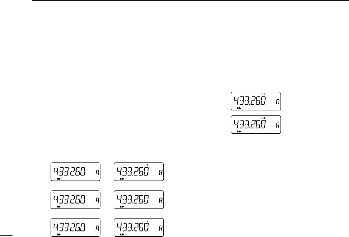
71
9OTHER FUNCTIONS
■Tone/DTCS squelch
qSet the desired operating frequency, CTCSS tone and
DTCS code.
wPush [2 TONE] for 1 sec. one or more times to activate the
tone or DTCS squelch. (T SQL or DTCS)
•Subaudible tone encoder “T,” tone squelch “T SQL,” pocket beep
“T SQLS,” DTCS squelch “DTCS,” DTCS beep “SDTCS”
and no tone operation are activated in order.
•Rotating [DIAL] while pushing [2 TONE] also selects the tone
functions.
eOperate the transceiver in the normal way.
rWhen the received signal includes a matching tone,
squelch opens and the signal can be heard.
•When the received signal’s tone does not match, tone squelch
does not open, however, the S-indicator shows signal strength.
•To open the squelch manually, push and hold [SQL].
■Pocket beep function
qSet the desired operating frequency.
wSet the desired CTCSS tone or DTCS code.
ePush [2 TONE] for 1 sec. one or more times to activate the
pocket beep or DTCS beep. (T SQLSor SDTCS)
•Rotating [DIAL] while pushing [2 TONE] also selects the tone
functions.
rWhen a signal with the correct tone or code is received,
the transceiver emits beep tones for 30 sec. and flashes
“S”.
tPush [PTT] to answer or push [SQL] to stop the beeps and
flashing.
➲CONVENIENT
Store subaudible tone frequencies, DTCS code, DTCS phase
mode and tone/DTCS squelch ON/OFF settings in memories
(call) for easy recall.
FM DTCS SKIPP
FM SQL SKIPTP
Pocket beep
by CTCSS dode
Pocket beep
by DTCS code
FM SKIPP
FM SKIPTP
FM SQL SKIPTP
FM SQL SKIPTP
FM DTCS SKIPP
FM DTCS SKIPP
No tone operation
Subaudible tone encoder
Tone squelch
Pocket beep
DTCS beep
DTCS squelch
IC-T90A_IM.qxd 02.5.28 01:13 PM Page 74 (1,1)

72
9
OTHER FUNCTIONS
■Available tone frequencies
The transceiver has 50 tone frequencies for repeater and
tone squelch (CTCSS)/pocket beep operation. Separate tone
frequencies can be set for repeater and tone squelch/pocket
beep operation.
(unit: Hz)
The transceiver has 50 tone frequencies and consequently
their spacing is narrow compared with units having 38
tones. Therefore, some tone frequencies may receive in-
terference from adjacent tone frequencies.
■Available DTCS codes
The transceiver has 104 DTCS codes for DTCS squelch and
DTCS beep.
67.0
69.3
71.9
74.4
77.0
79.7
82.5
85.4
88.5
91.5
94.8
97.4
100.0
103.5
107.2
110.9
114.8
118.8
123.0
127.3
131.8
136.5
141.3
146.2
151.4
156.7
159.8
162.2
165.5
167.9
171.3
173.8
177.3
179.9
183.5
186.2
189.9
192.8
196.6
199.5
203.5
206.5
210.7
218.1
225.7
229.1
233.6
241.8
250.3
254.1
023
025
026
031
032
036
043
047
051
053
054
065
071
072
073
074
114
115
116
122
125
131
132
134
143
145
152
155
156
162
165
172
174
205
212
223
225
226
243
244
245
246
251
252
255
261
263
265
266
271
274
306
311
315
325
331
332
343
346
351
356
364
365
371
411
412
413
423
431
432
445
446
452
454
455
462
464
465
466
503
506
516
523
526
532
546
565
606
612
624
627
631
632
654
662
664
703
712
723
731
732
734
743
754
oo
OTHER FUNCTIONS
IC-T90A_IM.qxd 02.5.28 01:13 PM Page 75 (1,1)
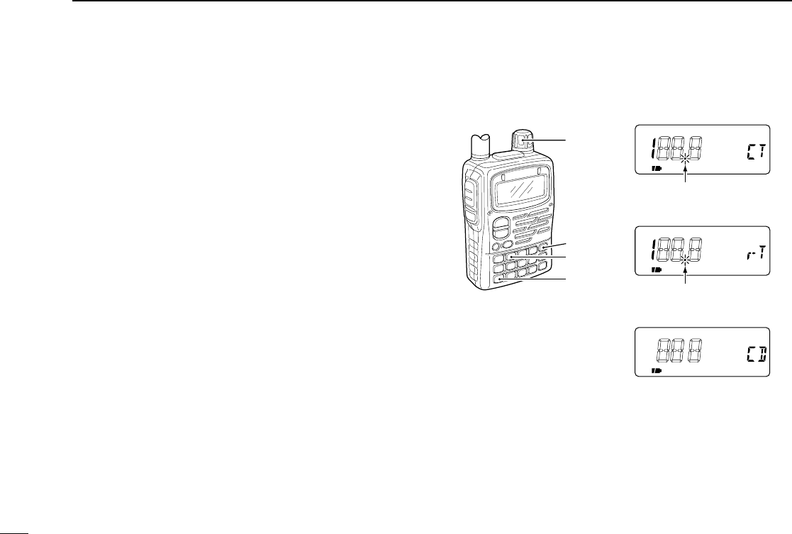
73
9OTHER FUNCTIONS
■Tone scan
The transceiver can detect the subaudible tone frequency and
DTCS code in a received signal. By monitoring a signal that
is being transmitted on a repeater input frequency, you can
determine the tone frequency required to access the repeater.
qSet the desired frequency or memory channel to be
checked for a tone frequency or DTCS code.
wPush [2 TONE] for 1 sec. one or more times to activate the
repeater tone, tone squelch or DTCS squelch. (T, T SQL
or DTCS)
•Rotating [DIAL] while pushing [2 TONE] also selects the tone
functions.
ePush [7 T.SCAN] for 1 sec. to start the tone scan.
•To change the scanning direction, rotate [DIAL].
rWhen the tone frequency or DTCS code is decoded, the
set mode contents are programmed with the frequency or
code.
•The tone scan pauses approx. 10 sec. when a tone frequency or
DTCS code is detected.
•The decoded tone frequency is used for the repeater tone fre-
quency when the tone squelch or DTCS squelch is OFF.
•The decoded tone frequency is used for the tone squelch fre-
quency when the tone squelch is ON.
•The decoded DTCS code is used for the DTCS code when the
DTCS squelch is ON.
•“CT,” “rT” or “CD” appears according to the tone setting.
tPush [VFO] to stop the scan.
•If the scan is cancelled before the transceiver detects the tone
or code, the set mode contents are not changed.
[DIAL]
[VFO]
[2 TONE]
[7 T.SCAN]
Tone scan for tone squelch
Tone scan for repeater tone
Tone scan for DTCS squelch
Flashes while scanning.
Flashes while scanning.
IC-T90A_IM.qxd 02.5.28 01:13 PM Page 76 (1,1)

74
9
OTHER FUNCTIONS
■Beep tones
You can select to have confirmation beeps sound at the push
of a switch. The output level can be adjusted within 32 levels
or to the related level of the volume. (p. 58)
You can select silent operation by turning beep tones OFF.
(p. 59)
These can be selected in set mode.
■Dial speed acceleration
The dial speed acceleration automatically speeds up the tun-
ing dial speed when rotating the [DIAL] rapidly.
This function can be turned ON and OFF in set mode. (p. 60)
■Lock function
The lock function prevents accidental frequency changes and
accidental function access.
➥Push [CALL/TV LOCK] for 1 sec. to toggle the lock function
ON and OFF.
•[PWR], [VOL], [SQL] and [PTT] can still be accessed while the
lock function is ON. (default)
DLock function effect
While the lock function is ON, [PWR], [VOL], [SQL] and [PTT]
can still be accessed. Accessible switches can be set to 1 of 4
groups in expanded set mode 1. (p. 63)
•“NORMAL”: [PWR], [VOL], [SQL] and [PTT] are accessible.
•“NO SQL”: [PWR], [SQL] and [PTT] are accessible.
•“NO VOL”: [PWR], [VOL] and [PTT] are accessible.
•“ALL”: [PWR] and [PTT] are accessible.
FM SKIPP
Lock indication
oo
OTHER FUNCTIONS
IC-T90A_IM.qxd 02.5.28 01:13 PM Page 77 (1,1)
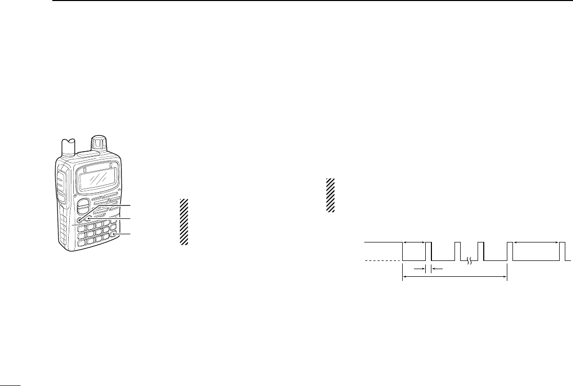
75
9OTHER FUNCTIONS
■Morse code synthesizer
The transceiver announces the operating frequency or TV
channel number in Morse code. The keying speed can be ad-
justed within 10 to 25 WPM in 5 WPM steps for your conve-
nience. This can be selected in expanded set mode 2. (p. 66)
➥Push [BAND] for 1 sec. for
frequency announcement
when the Morse code syn-
thesizer is turned ON.
Turning power ON while
pushing [CALL/TV] also
toggles the Morse code
synthesizer ON or OFF.
■Power save
The power save function reduces the current drain to con-
serve battery power.
The power save duty cycle, the ratio of receive circuit on to
receive circuit off while standing by, can be set to automatic
(default), 1:1, 1:4, 1:8, 1:16 or OFF in set mode. (p. 60)
•“AUTO” selects “1:4” duty ratio when receiving no signal for 5 sec.,
then “1:8” 60 sec. after that.
When automatic is selected, the power save automatically
turns OFF while operating with an external DC power sup-
ply. (11.0 V DC ±5%)
Circuit on
Circuit off
150 msec.
60 sec.
600 msec. 1200 msec.
No signal
5 sec.
[PWR]
[BAND]
[CALL/TV]
IC-T90A_IM.qxd 02.5.28 01:13 PM Page 78 (1,1)

76
9
OTHER FUNCTIONS
■Time-out timer
To prevent accidental prolonged transmission, etc., the trans-
ceiver has a time-out timer. This timer cuts a transmission
OFF after 1, 3, 5 or 10 min. of continuous transmission. This
timer can be cancelled (default).
Approx. 10 sec. before the time-out timer is activated, the
transceiver emits a beep tone as a warning.
This can be selected in expanded set mode 2. (p. 65)
■PTT lock
To prevent accidental transmission, etc., the transceiver has a
PTT lock function.
This can be selected in expanded set mode 1. (p. 64)
■Auto power OFF
The transceiver can be set to automatically turn OFF after a
specified period with beep in which no switch is pushed.
120 min., 90 min., 60 min., 30 min. and OFF can be speci-
fied. The specified period is retained even when the trans-
ceiver is turned OFF by the auto power-off function. To cancel
the function, select “OFF” in the auto power-off item in set
mode.
This can be selected in set mode. (p. 59)
■Auto power ON
The transceiver can be set to automatically turn ON after a
specified period. The timer can be selected within 30 min. to
24 hrs. in 30 min. steps.
This can be selected in expanded set mode 1. (p. 63)
When operating with battery pack or case and the battery
is exhausted, auto power-on does not function.
oo
OTHER FUNCTIONS
IC-T90A_IM.qxd 02.5.28 01:13 PM Page 79 (1,1)
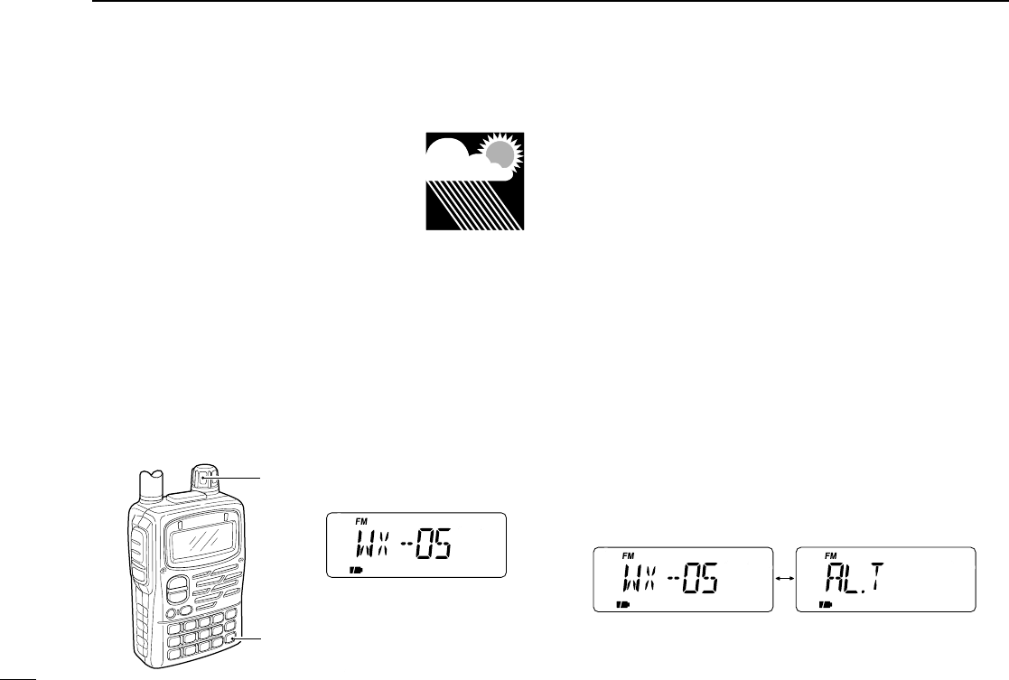
77
9OTHER FUNCTIONS
■Weather channel operation
(USA version only)
There are 10 weather channels for moni-
toring weather channels from the NOAA
(National Oceanographic and Atmospheric
Administration) broadcasts.
DDWeather channel selection
qPush [CALL/TV LOCK] one or two times to select weather
channel mode.
•“WX” and the weather channel number appear.
wRotate [DIAL] to select the desired weather channel.
qPush [VFO] or [MR] to return to the previous frequency.
DDWeather alert function
NOAA broadcast stations transmit weather alert tones before
important weather announcements. When the weather alert
function is turned ON, the selected weather channel is moni-
tored each 5 sec. for the announcement. When the alert sig-
nal is detected, the “AL.T” and the WX channel are displayed
alternately and sounds a beep tone until the transceiver is
operated. The previously selected (used) weather channel is
checked periodically during standby or while scanning.
qSelect the desired weather channel.
wTurn the weather alert function ON in set mode.
➥Push [8 SET] for 1 sec. to enter set mode.
➥Rotate [DIAL] to select the [WX ALT] (weather alert
function), then push [8 SET].
➥Rotate the [DIAL] to set ON.
➥Push [VFO] to exit set mode.
eSets the desired stand-by condition.
•Selects VFO, memory or call channel.
•Scan or priority watch operation can also be selected.
rWhen the alert is detected, a beep sounds and the follow-
ing indication will be displayed.
tTurn the weather alert function OFF in set mode.
[DIAL]
[
CALL/TV
LOCK]
Shows above indications alternately.
IC-T90A_IM.qxd 02.5.28 01:13 PM Page 80 (1,1)

78
9
OTHER FUNCTIONS
NOTE: While receiving a signal (on a frequency other than
the weather alert ON frequency), the receiving signal or
audio will be interrupted momentarily every 5 sec. (approx.)
in case the alert function is turned ON. This symptom is
caused by the WX alert function. To cancel these symp-
toms, set the weather alert item OFF in set mode.
oo
OTHER FUNCTIONS
IC-T90A_IM.qxd 02.5.28 01:13 PM Page 81 (1,1)
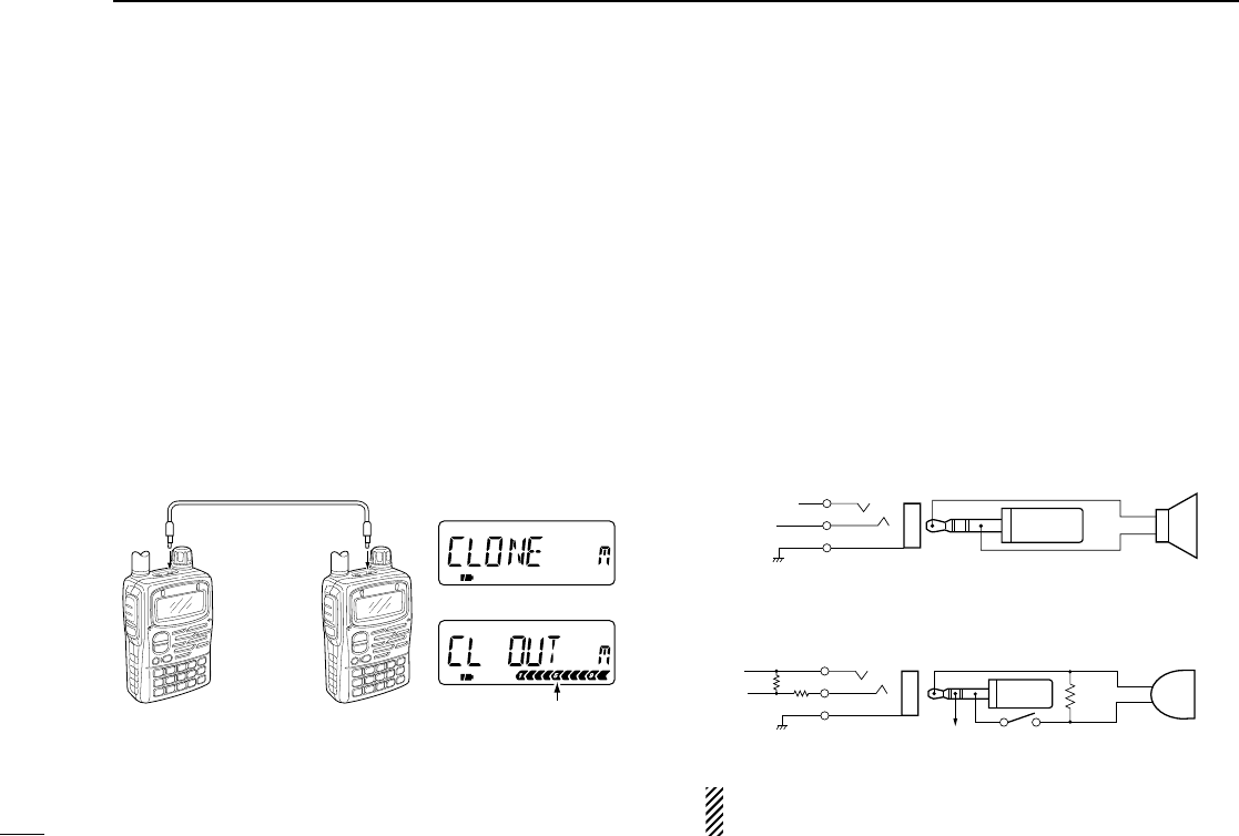
79
9OTHER FUNCTIONS
■Cloning function
The IC-T90A has transceiver-to-transceiver data cloning ca-
pability. This function is useful when you want to copy all of
the programmed contents from one IC-T90A to another. An
optional OPC-474 CLONING CABLE is required.
qConnect an optional OPC-474 between both [SP] jacks.
wWhile pushing [8 SET] and [MR], push [PWR] for 1 sec. to
enter cloning mode.
•“CLONE” appears.
ePush [PTT] on the “master” transceiver.
•“CL OUT” appears and the signal indicator shows that cloning is
taking place.
rPush [PWR] for 1 sec. to turn power OFF.
The optional CS-T90A CLONING SOFTWARE and the optional
OPC-478 CLONING CABLE are available to clone and edit
contents with a PC (for Microsoft®Windows®95/98/ME).
Microsoft®and Windows®are registered trademarks of Microsoft Corporation in
the U.S.A. and other countries.
■[SP/MIC] jacks
To connect external equipment such as speaker, microphone,
TNC, etc. refer to the diagram below.
The center terminal of [MIC] outputs 3.2 V DC via 330 Ω
register.
External
speaker
[SP] jack
SP
SP
GND
ø3.5 mm
plug
[MIC] jack
33 kΩ
MIC
MIC
GND
External
microphone
ø2.5 mm
plug
PTT
3.2 V (See below)
Impedance 8 Ω
Impedance 2 kΩ
MIC
3.2V
MIC GND
SP (AF OUT)
REMOTE
SP GND
OPC-474 to
[SP]
to
[SP]
Signal indicator shows that
cloning is taking place.
Cloning period
Cloning mode
IC-T90A_IM.qxd 02.5.28 01:13 PM Page 82 (1,1)
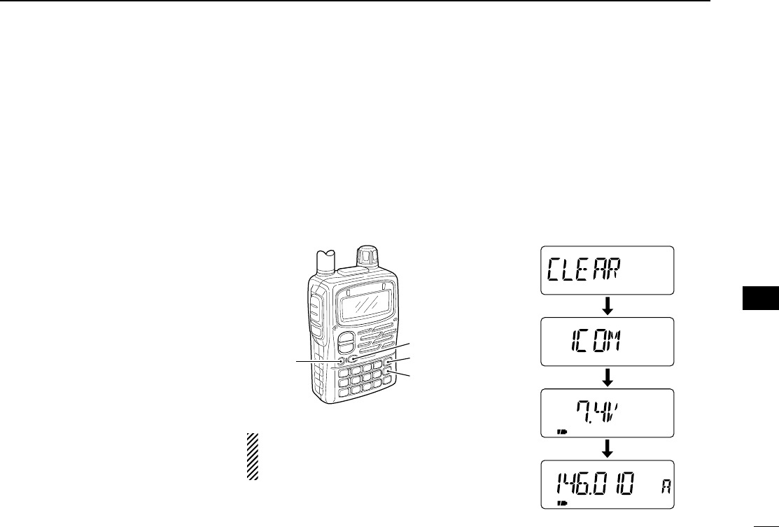
80
9
OTHER FUNCTIONS
■Resetting
The function display may occasionally
display erroneous information (e.g.
when first applying power). This may be
caused externally by static electricity or
by other factors.
If this problem occurs, turn power OFF.
After waiting a few seconds, turn power
ON again. If the problem persists, per-
form either or both procedures below.
•All reset
Reset the CPU before operating the
transceiver for the first time, or when
the internal CPU malfunctions to clear
and return all programmed contents to
their default settings.
•Partial reset
If you want to initialize the operating
conditions (VFO frequency, VFO set-
tings, set mode contents) without clear-
ing the memory contents, a partial
resetting function is available for the
transceiver.
DAll reset
qPush [POWER] for 2 sec. to turn
power OFF.
wWhile pushing [BAND], [VFO] and
[MR], turn power ON to reset the
CPU.
•“CLEAR” appears when resetting the
CPU.
CAUTION: Resetting the CPU re-
turns all programmed contents to
their default settings.
DPartial reset
qPush [POWER] for 2 sec. to turn
power OFF.
wWhile pushing [VFO], turn power ON
to partially reset the transceiver.
•Total resetting
FM SKIPP
[PWR]
[BAND]
[VFO]
[MR]
oo
OTHER FUNCTIONS
IC-T90A_IM.qxd 02.5.28 01:13 PM Page 83 (1,1)
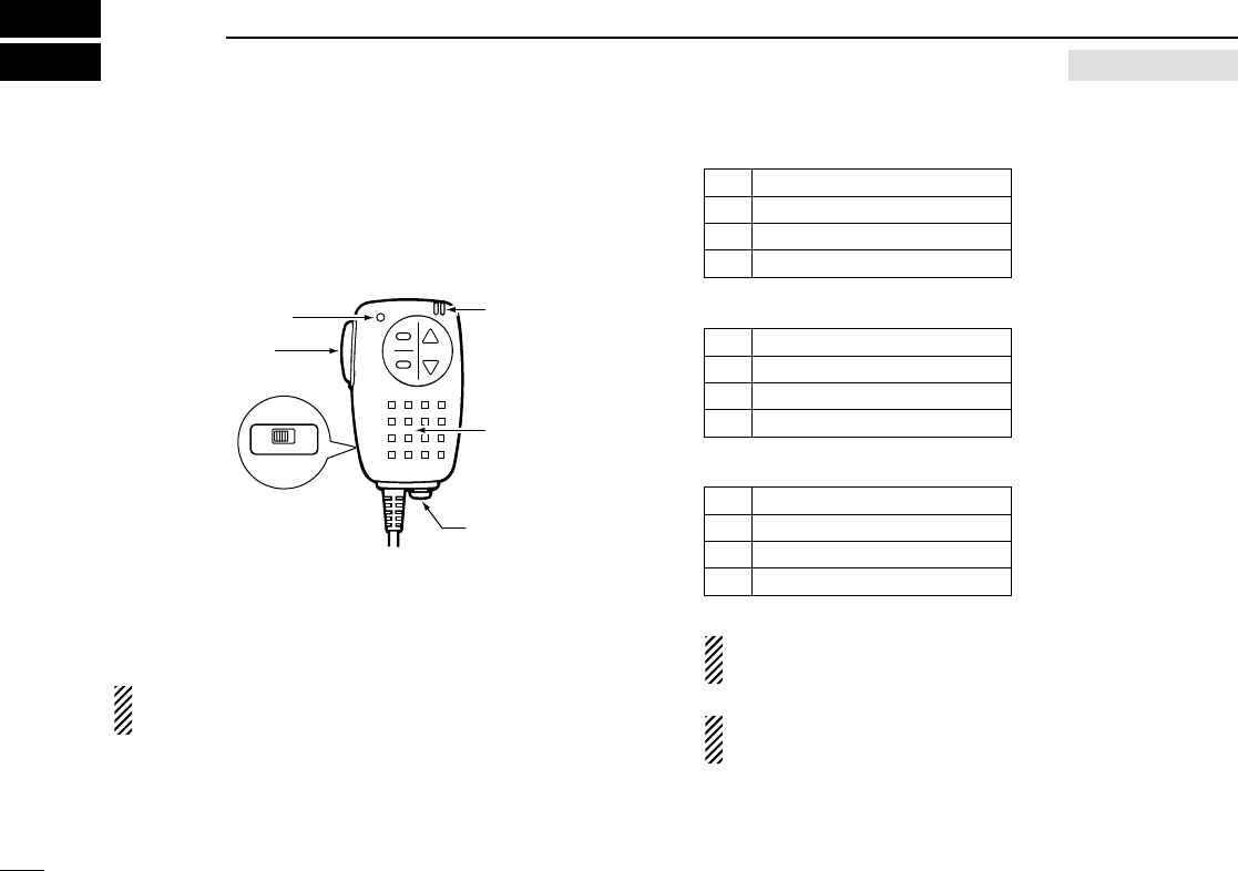
81
10 HM-75A REMOTE CONTROL MICROPHONE
The optional HM-75A allows you to remotely select operating
frequencies, memory channels, etc.
Remote control functions can be selected from 3 settings.
This can be selected in set mode. (p. 56)
The HM-75A has a lock switch on the backside to prevent ac-
cidental frequency changes, etc.
Be sure to turn power OFF when plugging the HM-75A in
the [SP/MIC] jacks.
•NORM-1: (default)
[A] Selects band.
[B] Toggles VFO and memory.
[Y] [UP]
[Z] [DOWN]
•NORM-2:
[A] Toggles monitor function.
[B] Toggles VFO and memory.
[Y] [UP]
[Z] [DOWN]
•SIMPLE:
[A] Toggles monitor function.
[B] Selects call channel C0.
[Y] Selects memory Ch 000.
[Z] Selects memory Ch 001.
VFO mode cannot be selected via the microphone when
SIMPLE mode is selected.
SIMPLE mode can select only 3 channels and is useful for
group operations during touring, etc.
A
OFF ON
LOCK
B
PTT switch
Transmit LED
Earphone jack
Microphone
Speaker
OPTIONAL
IC-T90A_IM.qxd 02.5.28 01:13 PM Page 84 (1,1)

82
11
TROUBLESHOOTING
PROBLEM POSSIBLE CAUSE SOLUTION REF.
No power comes ON. •The batteries are exhausted.
•The battery polarity is reversed.
•Replace the batteries or charge the battery pack.
•Check the battery polarity.
pgs. 1, 16
p. 1
No sound comes from the
speaker.
•Volume level is too low.
•Different tone is selected with tone/DTCS
squelch.
•Push [Y] to a suitable level.
•Check the tone using tone/DTCS scan.
p. 17
p. 70
Transmitting is
impossible.
•The batteries are exhausted.
•A frequency outside of the 50/144/400
MHz amateur bands is set.
•Replace the batteries or charge the battery pack.
•Reset the frequency inside the 50/144/400 MHz
amateur bands.
pgs. 13, 16
p. 19, 87
Tuning dial or [Z]/[Y]
function is strange.
•Tuning dial and [Z]/[Y] functions are
exchanged.
•Push [1 V↔D] for 1 sec. to cancel the function. p. 23
No beeps sound. •Beep tones are turned OFF or the beep
tone level is low.
•Turn beep tones ON or set the beep tone level to
appropriate level in set mode.
pgs. 58,
59
No contact possible with
another station.
•Different tone is selected with tone/DTCS
squelch.
•Check the tone using tone scan. p. 70
Receive audio is
distorted.
•The operating mode is not selected
correctly.
•Select a suitable operating mode in set mode. p. 21
Desired set mode item
cannot be selected.
•The desired set mode item is in expanded
set mode 1 or 2.
•Some set mode items can be selected
from VFO or memory mode only.
•Turn the expanded set mode 1 or 2 ON.
•Enter set mode from appropriate operating mode.
p. 55
pgs. 17, 18
22, 27
Frequency cannot be set. •The lock function is activated.
•Memory or call channel is selected.
•
Push [CALL/TV LOCK] for 1 sec. to cancel the function.
•Push [VFO] to select VFO mode.
p. 74
p. 20
If your transceiver seems to be malfunctioning, please check
the following points before sending it to a service center.
!!00
!!11
HM-75
REMOTE CONTROL MICROPHONE
TROUBLESHOOTING
IC-T90A_IM.qxd 02.5.28 01:13 PM Page 85 (1,1)

The following tables show the channels versus video and
audio frequencies depending on each version.
■U.S.A. channels ■CCIR channels
83
12 TV FREQUENCY TABLE
CH Video Audio
2 55.25 59.75
3 61.25 65.75
4 67.25 71.75
5 77.25 81.75
6 83.25 87.75
7 175.25 179.75
8 181.25 185.75
9 187.25 191.75
10 193.25 197.75
11 199.25 203.75
12 205.25 209.75
13 211.25 215.75
14 471.25 475.75
15 477.25 481.75
16 483.25 487.75
17 489.25 493.75
18 495.25 499.75
19 501.25 505.75
20 507.25 511.75
21 513.25 517.75
22 519.25 523.75
23 525.25 529.75
24 531.25 535.75
25 537.25 541.75
CH Video Audio
26 543.25 547.75
27 549.25 553.75
28 555.25 559.75
29 561.25 565.75
30 567.25 571.75
31 573.25 577.75
32 579.25 583.75
33 585.25 589.75
34 591.25 595.75
35 597.25 601.75
36 603.25 607.75
37 609.25 613.75
38 615.25 619.75
39 621.25 625.75
40 627.25 631.75
41 633.25 637.75
42 639.25 643.75
43 645.25 649.75
44 651.25 655.75
45 657.25 661.75
46 663.25 667.75
47 669.25 673.75
48 675.25 679.75
49 681.25 685.75
CH Video Audio
50 687.25 691.75
51 693.25 697.75
52 699.25 703.75
53 705.25 709.75
54 711.25 715.75
55 717.25 721.75
56 723.25 727.75
57 729.25 733.75
58 735.25 739.75
59 741.25 745.75
60 747.25 751.75
61 753.25 757.75
62 759.25 763.75
63 765.25 769.75
64 771.25 775.75
65 777.25 781.75
66 783.25 787.75
67 789.25 793.75
68 795.25 799.75
69 801.25 805.75
CH Video Audio
1 41.25 46.75
2 48.25 53.75
3 55.25 60.75
4 62.25 67.75
5 175.25 180.75
6 182.25 187.75
7 189.25 194.75
8 196.25 201.75
9 203.25 208.75
10 210.25 215.75
11 217.25 222.75
12 224.25 229.75
21 471.25 476.75
22 479.25 484.75
23 487.25 492.75
24 495.25 500.75
25 503.25 508.75
26 511.25 516.75
27 519.25 524.75
28 527.25 532.75
29 535.25 540.75
30 543.25 548.75
CH Video Audio
31 551.25 556.75
32 559.25 564.75
33 567.25 572.75
34 575.25 580.75
35 583.25 588.75
36 591.25 596.75
37 599.25 604.75
38 607.25 612.75
39 615.25 620.75
40 623.25 628.75
41 631.25 636.75
42 639.25 644.75
43 647.25 652.75
44 655.25 660.75
45 663.25 668.75
46 671.25 676.75
47 679.25 684.75
48 687.25 692.75
49 695.25 700.75
50 703.25 708.75
51 711.25 716.75
52 719.25 724.75
IC-T90A_IM.qxd 02.5.28 01:13 PM Page 86 (1,1)

■Australian channels
CH Video Audio
39 604.25 609.75
40 611.25 616.75
41 618.25 623.75
42 625.25 630.75
43 632.25 637.75
44 639.25 644.75
45 646.25 651.75
46 653.25 658.75
47 660.25 665.75
48 667.25 672.75
49 674.25 679.75
50 681.25 686.75
51 688.25 693.75
52 695.25 700.75
53 702.25 707.75
54 709.25 714.75
55 716.25 721.75
56 723.25 728.75
57 730.25 735.75
58 737.25 742.75
59 744.25 749.75
60 751.25 756.75
61 758.25 763.75
62 765.25 770.75
CH Video Audio
0 46.25 51.75
1 57.25 62.75
2 64.25 69.75
3 86.25 91.75
4 95.25 100.75
5 102.25 107.75
5A 138.25 143.75
6 175.25 180.75
7 182.25 187.75
8 189.25 194.75
9 196.25 201.75
10 209.25 214.75
11 216.25 221.75
28 527.25 532.75
29 534.25 539.75
30 541.25 546.75
31 548.25 553.75
32 555.25 560.75
33 562.25 567.75
34 569.25 574.75
35 576.25 581.75
36 583.25 588.75
37 590.25 595.75
38 597.25 602.75
■New Zealand
channels
CH Video Audio
1 45.25 50.75
2 55.25 60.75
3 62.25 67.75
4 175.25 180.75
5 182.25 187.75
6 189.25 194.75
7 196.25 201.75
8 203.25 208.75
9 210.25 215.75
10 217.25 222.75
11 224.25 229.75
■Taiwan channels
CH Video Audio
7 175.25 179.75
8 181.25 185.75
9 187.25 191.75
10 193.25 197.75
11 199.25 203.75
12 205.25 209.75
84
12
TV FREQUENCY TABLE
CH Video Audio
53 727.25 732.75
54 735.25 740.75
55 743.25 748.75
56 751.25 756.75
57 759.25 764.75
58 767.25 772.75
59 775.25 780.75
60 783.25 788.75
61 791.25 796.75
62 799.25 804.75
63 807.25 812.75
64 815.25 820.75
65 823.25 828.75
66 831.25 836.75
67 839.25 844.75
68 847.25 852.75
69 855.25 860.75
CH Video Audio
63 772.25 777.75
64 779.25 784.75
65 786.25 791.75
66 793.25 798.75
67 800.25 805.75
68 807.25 812.75
69 814.25 819.75
!!22
TV FREQUENCY TABLE
IC-T90A_IM.qxd 02.5.28 01:13 PM Page 87 (1,1)

85
12 TV FREQUENCY TABLE
■China channels
CH Video Audio
1 49.75 56.25
2 57.75 64.25
3 65.75 72.25
4 77.25 83.75
5 85.25 91.75
6 168.25 174.75
7 176.25 182.75
8 184.25 190.75
9 192.25 198.75
10 200.25 206.75
11 208.25 214.75
12 216.25 222.75
13 471.25 477.75
14 479.25 485.75
15 487.25 493.75
16 495.25 501.75
17 503.25 509.75
18 511.25 517.75
19 519.25 525.75
20 527.25 533.75
21 535.25 541.75
22 543.25 549.75
23 551.25 557.75
24 559.25 565.75
25 607.25 613.75
26 615.25 621.75
27 623.25 629.75
CH Video Audio
28 631.25 637.75
29 639.25 645.75
30 647.25 653.75
31 655.25 661.75
32 663.25 669.75
33 671.25 677.75
34 679.25 685.75
35 687.25 693.75
36 695.25 701.75
37 703.25 709.75
38 711.25 717.75
39 719.25 725.75
40 727.25 733.75
41 735.25 741.75
42 743.25 749.75
43 751.25 757.75
44 759.25 765.75
45 767.25 773.75
46 775.25 781.75
47 783.25 789.75
48 791.25 797.75
49 799.25 805.75
50 807.25 813.75
51 815.25 821.75
52 823.25 829.75
53 831.25 837.75
54 839.25 845.75
CH Video Audio
55 847.25 853.75
56 855.25 861.75
57 863.25 869.75
58 871.25 877.75
59 879.25 885.75
60 887.25 893.75
61 895.25 901.75
62 903.25 909.75
63 911.25 917.75
64 919.25 925.75
65 927.25 933.75
66 935.25 941.75
67 943.25 949.75
68 951.25 957.75
■Indonesian channels
CH Video Audio
2 48.25 53.75
3 55.25 60.75
4 62.25 67.75
5 175.25 180.75
6 182.25 187.75
7 189.25 194.75
8 196.25 201.75
9 203.25 208.75
10 210.25 215.75
11 217.25 222.75
21 471.25 476.75
22 479.25 484.75
23 487.25 492.75
24 495.25 500.75
25 503.25 508.75
26 511.25 516.75
27 519.25 524.75
28 527.25 532.75
29 535.25 540.75
30 543.25 548.75
31 551.25 556.75
32 559.25 564.75
33 567.25 572.75
34 575.25 580.75
35 583.25 588.75
36 591.25 596.75
37 599.25 604.75
CH Video Audio
38 607.25 612.75
39 615.25 620.75
40 623.25 628.75
41 631.25 636.75
42 639.25 644.75
43 647.25 652.75
44 655.25 660.75
45 663.25 668.75
46 671.25 676.75
47 679.25 684.75
48 687.25 692.75
49 695.25 700.75
50 703.25 708.75
51 711.25 716.75
52 719.25 724.75
53 727.25 732.75
54 735.25 740.75
55 743.25 748.75
56 751.25 756.75
57 759.25 764.75
58 767.25 772.75
59 775.25 780.75
60 783.25 788.75
61 791.25 796.75
62 799.25 804.75
63 807.25 812.75
64 815.25 820.75
IC-T90A_IM.qxd 02.5.28 01:13 PM Page 88 (1,1)

86
12
TV FREQUENCY TABLE
■FOT channels
CH Video Audio
4 175.25 181.75
5 183.25 189.75
6 191.25 197.75
7 199.25 205.75
8 207.25 213.75
9 215.25 221.75
CH Video Audio
65 823.25 828.75
66 831.25 836.75
67 839.25 844.75
68 847.25 852.75
69 855.25 860.75
■Italian channels
CH Video Audio
A 53.75 59.25
B 62.25 67.75
C 82.25 87.75
D 175.25 180.75
E 183.25 188.75
F 192.25 197.75
G 201.25 206.75
H 210.25 215.75
H1 217.25 222.75
H2 224.25 229.75
21 471.25 476.75
22 479.25 484.75
23 487.25 492.75
24 495.25 500.75
25 503.25 508.75
26 511.25 516.75
27 519.25 524.75
28 527.25 532.75
29 535.25 540.75
30 543.25 548.75
31 551.25 556.75
32 559.25 564.75
33 567.25 572.75
34 575.25 580.75
35 583.25 588.75
36 591.25 596.75
37 599.25 604.75
CH Video Audio
38 607.25 612.75
39 615.25 620.75
40 623.25 628.75
41 631.25 636.75
42 639.25 644.75
43 647.25 652.75
44 655.25 660.75
45 663.25 668.75
46 671.25 676.75
47 679.25 684.75
48 687.25 692.75
49 695.25 700.75
50 703.25 708.75
51 711.25 716.75
52 719.25 724.75
53 727.25 732.75
54 735.25 740.75
55 743.25 748.75
56 751.25 756.75
57 759.25 764.75
58 767.25 772.75
59 775.25 780.75
60 783.25 788.75
61 791.25 796.75
62 799.25 804.75
63 807.25 812.75
64 815.25 820.75
CH Video Audio
65 823.25 828.75
66 831.25 836.75
67 839.25 844.75
68 847.25 852.75
69 855.25 860.75
!!22
TV FREQUENCY TABLE
IC-T90A_IM.qxd 02.5.28 01:13 PM Page 89 (1,1)

DGeneral
•Frequency coverage : (unit: MHz)
*1Guaranteed 440–450 MHz only
*2Guaranteed 430–440 MHz only
•Mode : FM, AM (Rx only),
WFM (Rx only)
•No. of memory channels : 555 (500 regular, 50 scan edges,
5 call)
•Usable temp. range : +14°F to +140°F;
–10°C to +60°C
•Tuning steps : 5, 6.25, 8.33, 9, 10, 12.5, 15, 20,
25, 30, 50, 100 and 200 kHz
•Frequency stability : ±6 ppm (+14°F to +140°F)
•Power supply : 5.5 to 11.5 V DC or specified
battery pack
•Current drain (at 8.0 V DC):
Tx High 50 MHz 2.0 A (typical)
144, 430 MHz 2.0 A (typical)
Tx Low 50, 144 MHz 0.8 A (typical)
430 MHz 1.2 A (typical)
Rx rated audio 220 mA (typical)
standby 100 mA (typical)
power saved 65 mA (typical)
•Antenna connector : SMA (50 Ω)
•Dimensions : 2 9⁄32(W)×37⁄16(H)×15⁄32(D) in;
(projections not included) 58(W)×87(H)×29(D) mm
•Weight (approx.) : 8 15⁄32 oz; 240 g
(with antenna and BP-217)
87
13 SPECIFICATIONS
U.S.A
Canada
Asia
Australia
Korea
Taiwan
General
Transmit
50–53.995,
144–148, 430–450*1
50–53.995,
144–148, 430–440
50–53.995,
144–148, 420–450*2
50–53.995,
144–146, 430–440
50–50.2, 144–146,
430–432
50–53.995,
144–148, 430–440
Receive
0.495–824.000,
849–869.000,
894–999.990
0.495–999.990
0.495–53.995,
108–135.995,
144–148, 420–450
0.495–29.995,
50–53.995,
88–107.995,
144–146, 430–440
50–50.2,
76–107.995,
144–146, 430–440
0.495–999.990
IC-T90A_IM.qxd 02.5.28 01:13 PM Page 90 (1,1)

88
13
SPECIFICATIONS
DReceiver
•Receive system : Double-conversion
superheterodyne
•Intermediate frequencies : 1st 69.45 MHz (FM/AM)
13.35 MHz (WFM)
2nd 450 kHz
•Sensitivity (except spurious points; typical values):
FM 1.625–4.995 MHz 0.4 µV
(at 12 dB SINAD) 5.000–49.995 MHz 0.18 µV
50.000–54.000 MHz 0.16 µV
54.005–143.995 MHz 0.18 µV
144.000–148.000 MHz 0.16 µV
148.005–221.995 MHz 0.4 µV
222.000–225.000 MHz 0.32 µV
225.005–246.995 MHz 0.4 µV
247.000–429.995 MHz 0.32 µV
430.000–450.000 MHz 0.16 µV
450.005–832.990 MHz 0.32 µV
833.000–999.990 MHz 1 µV
WFM 40.000–108.0 MHz 1 µV
(at 12 dB SINAD) 175–221.995 MHz 1.8 µV
470–770 MHz 3.2 µV
AM 0.495–4.995 MHz 1.3 µV
(at 10 dB S/N) 5.000–29.995 MHz 0.56 µV
118.000–136.000 MHz 0.5 µV
222.000–229.995 MHz 0.79 µV
320.000–329.995 MHz 1 µV
•Selectivity (except WFM) : Less than 15 kHz/–9 dB
More than 30 kHz/–60 dB
•Spurious and image rejection ratio:
50, 144 MHz Less than –60dB
430 (440) MHz Less than –50dB
(except half IF, 2nd image, 50 MHz band IF and WFM)
•Audio output power : 0.2 W typical at 10%
(at 8.0 V DC) distortion with an 8Ωload
•Ext. speaker connector : 2-conductor 3.5(d) mm;
1⁄8˝/8Ω
DTransmitter
•Modulation system : Variable reactance frequency
modulation
•Output power : High 5 W
(at 8.0 V DC) Low 0.5 W
•Spurious emissions : Less than –60 dB
•Max. frequency deviation: ±5.0 kHz
•Ext. MIC connector : 3-conductor 2.5(d) mm;
1⁄10˝/2 kΩ
All stated specifications are subject to change without
notice or obligation.
!!33
SPECIFICATIONS
IC-T90A_IM.qxd 02.5.28 01:13 PM Page 91 (1,1)
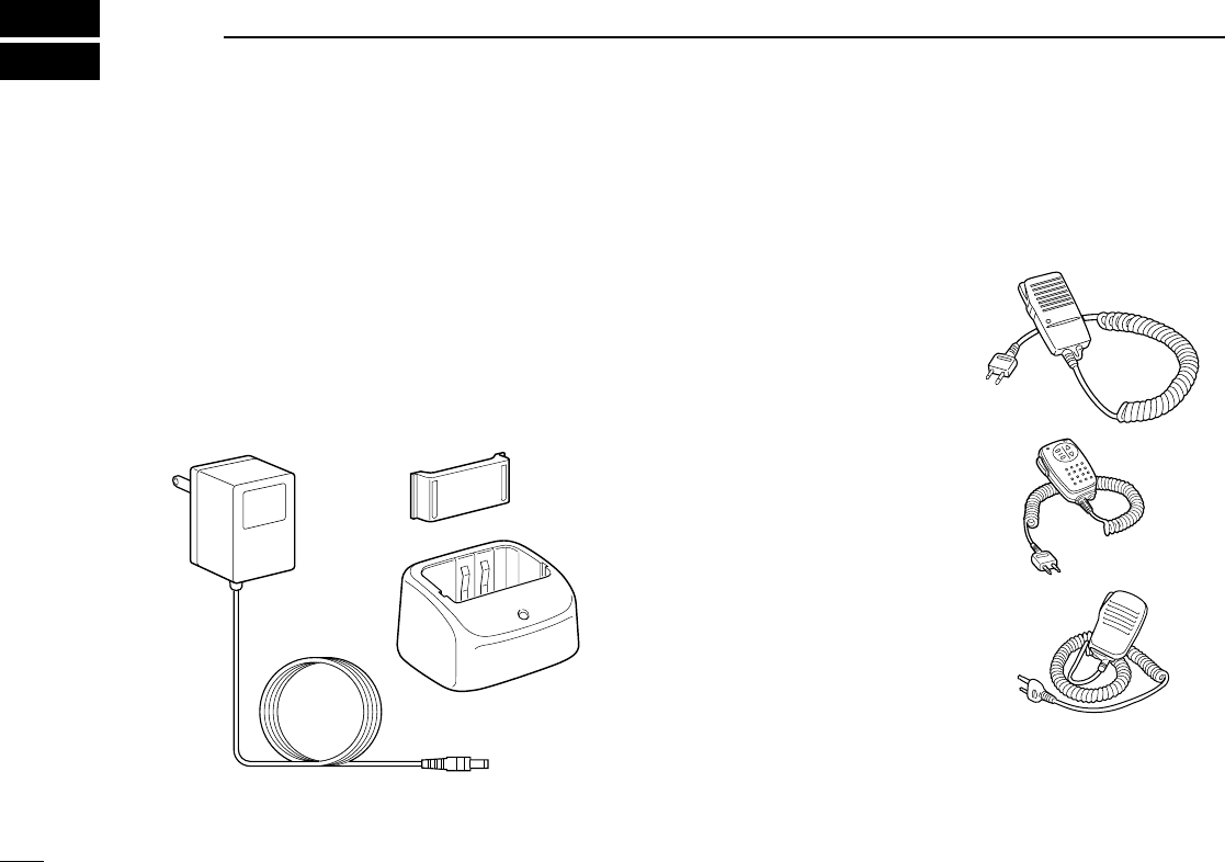
AD-92SMA ANTENNA CONNECTOR ADAPTER
Allows you to connect an antenna with a BNC connector.
(SMA to BNC adapter)
BC-110AR/D/DR WALL CHARGER
Regularly charges BP-217 Li-ion battery pack in 15 hrs.
BC-139 DESKTOP CHARGER
Rapidly charges BP-217 Li-ion battery pack in 2 hrs. and 30
min.
BP-216 BATTERY CASE
Battery case for R6 (AA) ×2 alkaline batteries.
BP-217 Li-Ion BATTERY PACK
7.4 V/1300 mAh Lithium Ion battery pack. Approx. 6 hrs. and
20 min. operating time at 50M band with high power, Tx : Rx :
Standby = 1:1:8.
HM-46 SPEAKER-MICRO-
PHONE
Slim dimensions. Equipped
with an earphone jack and a
transmit indicator.
HM-75A REMOTE CONTROL
MICROPHONE
Allows you to remotely select
operating channels, etc.
HM-131 SPEAKER-MICRO-
PHONE
For operation while conve-
niently hanging the transceiver
from your belt, etc.
HM-128 EARPHONE-MICROPHONE
Ideal for hands-free operation by clipping the microphone with
PTT switch to your lapel or breast pocket.
BC-123
(supplied
with BC-139)
Charger adapter
Desktop charger
89
14 OPTIONS
HM-46
HM-75A
HM-131
IC-T90A_IM.qxd 02.5.28 01:13 PM Page 92 (1,1)
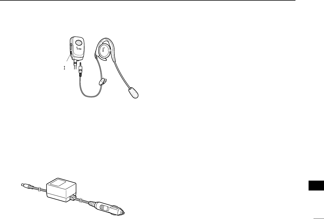
HS-94 EARHOOK
HEADSET + VS-1
VOX/PTT UNIT
Flexible boom micro-
phone and rotating ear-
piece with a spring
earhook.
SP-13 EARPHONE
Provides clear receive
audio in noisy environ-
ments.
LC-152A CARRYING CASE
Helps protect the transceiver from scratches, etc.
CP-19
CIGARETTE LIGHTER CABLE WITH NOISE FILTER
Used for operation and charging a battery pack connected to
the transceiver via a DC power source. (11.5–16 V DC)
CS-T90A CLONING SOFTWARE + OPC-478 CLONING
CABLE
Allows you to transfer data from memories, etc. and quickly
and easily edit and store data via a PC for Microsoft®
Windows®95/98 and ME. 1 RS-232C (COM) port is required.
OPC-474 CLONING CABLE
Used for handheld-to-handheld cloning.
CP-19
90
14
OPTIONS
Microsoft®and Windows®are registered trademarks of Microsoft Cor-
poration in the U.S.A. and other countries.
VOX
PTT
HS-94
VS-1
!!44
OPTIONS
IC-T90A_IM.qxd 02.5.28 01:13 PM Page 93 (1,1)
Blank page
IC-T90A_IM.qxd 02.5.28 01:13 PM Page 94 (1,1)
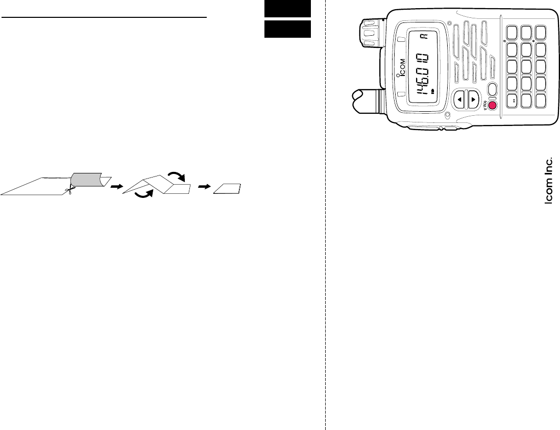
■ TV channel mode selection
Push [CALL/TV] several times.
■ TV channel selection
Rotate [DIAL].
■ TV channel skip setting
q Select TV channel mode.
w Rotate [DIAL] to select desired
channel.
e Push and hold [5 SKIP] for 1 sec.
■ Cancelling skip setting
q Select TV channel mode.
w While pushing [BAND], rotate
[DIAL] to select desired skip
channel.
e Push and hold [SKIP] for 1 sec.
■ Exchange [DIAL] and [∫]/[√]
assignment
Push and hold [1 V↔D] for 1 sec.
■ Key lock function
Push and hold [CALL/TV] for 1 sec. to
turn the lock function ON and OFF.
■ SET mode operation
q Push and hold [8 SET] for 1 sec.
w Rotate [DIAL] to select SET mode
item.
e Push [8 SET] momentarily, then
rotate [DIAL] to change the setting.
r Push [8 SET] momentarily to return
to the condition of step w.
t Push [VFO] to exit the SET mode.
■ CPU reset operation
• ALL reset
q Turn power OFF.
w While pushing and holding [BAND],
[VFO] and [MR], turn power ON.
• Partial reset
q Turn power OFF.
w While pushing and holding [VFO],
turn power ON.
FM SKIPP
1
V D
2
TONE
BAND
D
3
H/L
MODE
SCAN
VFO
MHz
iC-t90a
4
DUP
5
SKIP
6
M.N
0
RIT
MR
S.MW
7
T.SCAN
8
SET
9
TS
.
DTMF.M
CALL/TV
LOCK
A
B
C
MULTIBAND TRANSCEIVER
POCKET GUIDE
Important operating instructions are summed up in this and the following page
for your simple reference.
By cutting along the line and folding on the dotted line, it will become a card
sized operating guide which can easily be carried in a card case or wallet,
etc.
q Cut w Fold e Complete
<CUT HERE>
POCKET GUIDE
IC-T90A_IM.qxd 02.5.28 01:13 PM Page 95 (1,1)

QUICK REFERENCE
■ VFO/MEMORY MODE selection
VFO mode : Push [VFO].
MEMORY mode : Push [MR].
■ Changing frequency band
Push [BAND].
■ Frequency setting
q Select VFO mode.
w Rotate [DIAL], or enter the desired
frequency from the keypad.
[e.g. 1] 445.600 MHz
[4], [4], [5], [•], [6], [0], [0]
[e.g. 2] 0.684 MHz
[0], [•], [6], [8], [4]
■ Changing receiving mode
Push [MODE].
■ Adjusting audio output level
Push [∫]/[√] (continuously changes
while holding).
■ Adjusting squelch level
While pushing [SQL] rotate [DIAL].
■ MEMORY channel selection
q Select MEMORY mode.
w Rotate [DIAL], or use keypad.
■ MEMORY channel programming
[e.g.] Program 445.600 MHz into MR
CH 2
q Select VFO mode.
w Rotate [DIAL], or use keypad to
set 445.600 MHz.
e Push and hold [MR S.MW] for
1 sec. to indicate memory channels.
r Rotate [DIAL] to select MR CH 2.
t Push and hold [MR S.MW] for
1 sec. (VFO mode is selected after
programming.)
■ MEMORY channel clearing
q Select the desired memory channel.
w Push and hold [MR S.MW] for 1 sec.
w Push [CALL/TV] several times to
select “CLR”.
e Push and hold [MR S.MW] for
1 sec. to clear the information.
■ Scanning in VFO mode
q Select VFO mode.
w While pushing and holding [MODE
SCAN], rotate [DIAL] to select
scan edge from full (ALL), band
(BAND) and program (PROG
0–24) scans.
e Release [MODE SCAN] to start the
scan.
r Push [VFO] to stop the scan.
■ Scanning in MEMORY mode
q Select MEMORY mode.
w For the memory bank scan, push
[MR] to select memory bank mode
and push [BAND] to select the de-
sired memory bank.
e While pushing and holding [MODE
SCAN], rotate [DIAL] to select
scan mode from memory (ALL)
and bank (BANK) scans.
r Release [MODE SCAN] to start the
scan.
t Push [VFO] to stop the scan.
IC-T90A_IM.qxd 02.5.28 01:13 PM Page 96 (1,1)
IC-T90A_IM.qxd 02.5.28 01:13 PM Page 97 (1,1)

Count on us!
1-1-32 Kamiminami, Hirano-ku, Osaka 547-0003 Japan
A-6134H-1EX
Printed in Japan
© 2002 Icom Inc.
IC-T90A_IM.qxd 02.5.28 01:13 PM Page z (1,1)