ICOM orporated IC-V8 Amateur Scanning Transceiver User Manual IC V8
ICOM Incorporated Amateur Scanning Transceiver IC V8
UserManual.wiki
>
ICOM orporated
>
IC V8 User Manual
Instruction Manual
Navigation menu
Upload a User Manual
Namespaces
Wiki Guide
HTML
PDF
Info
Views
User Manual
Discussion / Help
Navigation
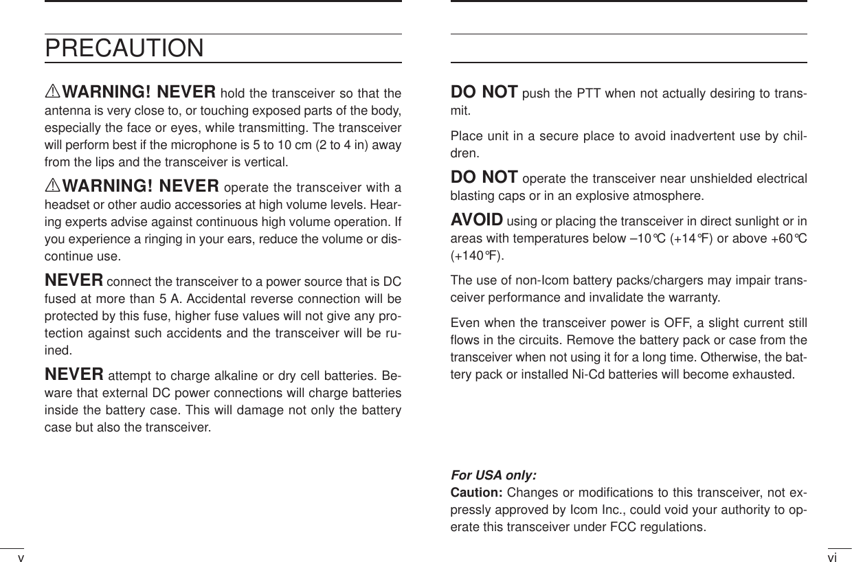
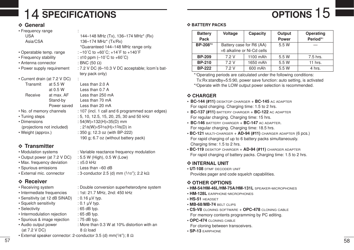
![PANEL DESCRIPTION1 21PANEL DESCRIPTION1rSQUELCH BUTTON [SQL]Push and hold to force the squelch open and to adjusts thesquelch level with [Y]/[Z] keys.tUP/DOWN KEYS [YY]/[ZZ]A Selects the operating channel or adjusts the squelch level.B Adjusts the audio level.• The function Bis available when “dial” is assigned with [VOL] inINITIAL SET MODE(p. 51).yKEY PAD (pgs. 3–6) Used to enter operating frequency, the DTMF codes, etc.uANTENNA CONNECTORConnects the supplied antenna.i[SP]/[MIC] JACKConnect an optional speaker-microphone or headset, if desired.The internal microphone and speaker will not function when ei-ther is connected.DExternal connectionNOTE: When connecting or disconnecting an external speaker-microphone, first turn the transceiver power OFF.oFUNCTION DISPLAY (pgs 7, 8)‘‘Switches, controls, keys andconnectorsqCONTROL DIAL [VOL]A Adjusts the audio level.B Selects the operating channel or adjusts the squelch level.• The function Bis available when “dial” is assigned with [VOL] inINITIAL SET MODE(p. 51).wPOWER SWITCH [POWER]Push for 1 sec. to turn the power ON and OFF.ePTT SWITCH [PTT]Push and hold to transmit; release to receive.qwertyouiSpeakerMicropho[SP] jackSPSPGND[MIC] jackMIC MICGND PTTMIC5 VMIC GNDSP (AF OUT)REMOTESP GNDExternal microphone(Nominal impedance 2k Ω)33 kΩExternal speaker(Nominal impedance 8 Ω)ø3.5 mmplugø2.5 mmplug](https://usermanual.wiki/ICOM-orporated/IC-V8/User-Guide-152120-Page-6.png)
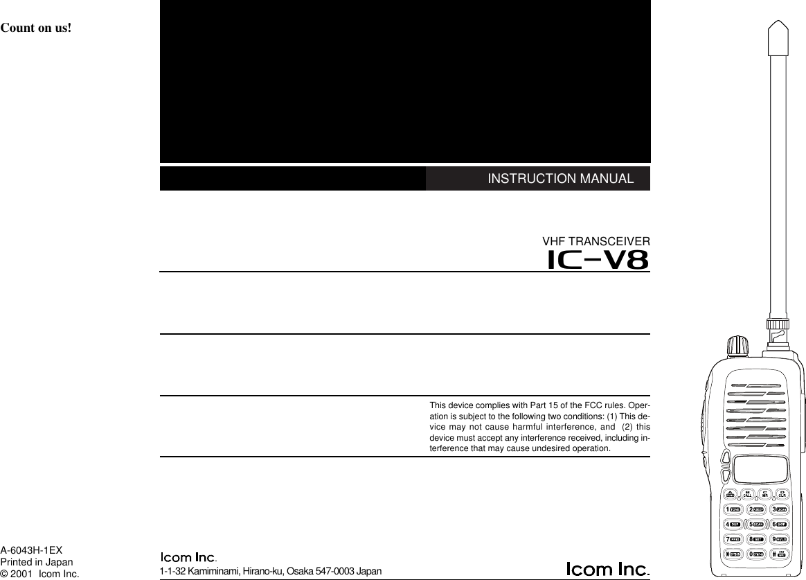
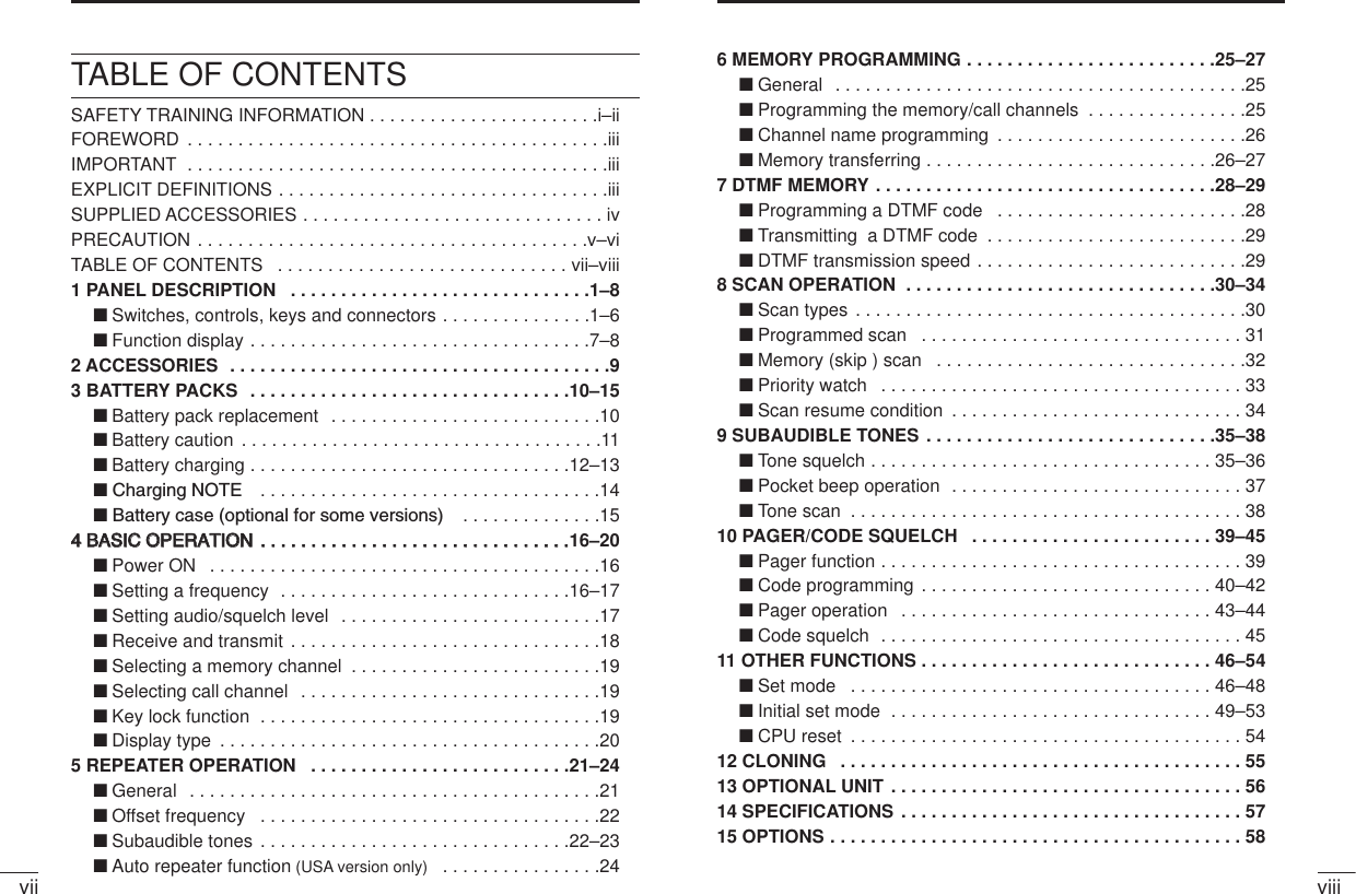
![Access to secondary functionSelect the call channel. (p. 19)Selects a memory mode. (p. 19)Selects VFO mode, aborts direct frequency input,or cancels scanning, etc. (pgs. 16, 31)Input digit “1” during frequency input, memory chan-nel selection, etc. (pgs. 16, 19)Input digit “2” during frequency input, memory chan-nel selection, etc. (pgs. 16, 19)Input digit “3” during frequency input, memory chan-nel selection, etc. (pgs. 16, 19)Input digit “4” during frequency input, memory chan-nel selection, etc. (pgs. 16, 19)Input digit “5” during frequency input, memory chan-nel selection, etc. (pgs. 16, 19)Input digit “6” during frequency input, memory chan-nel selection, etc. (pgs. 16, 19)KEY FUNCTION SECONDARY FUNCTION (After [A•FUNC] is pushed)[name][A•FUNC][B•CALL][C•MR][D•CLR][1•TONE][2•P.BEEP][3•T.SCAN][4•DUP][5•SCAN][6•SKIP]4131PANEL DESCRIPTION PANEL DESCRIPTIONDKey pad No function.No function.Entering into memory programming/editing mode. (p. 25)Programs/transfers VFO/memory or call channel contents intomemory channel/VFO when pushed for 1 sec. (pgs. 25, 26)No function.Selects a subaudible tone function. (pgs. 21, 35)Turn the pocket beep function ON and OFF. (p. 37)Starts the tone scanning. (pgs. 23, 38)Selects a duplex function (–duplex, +duplex, simplex). (p. 21)Starts scanning. (p. 31)Sets and cancels skip setting for memory skip scan during mem-ory mode. (p. 32)](https://usermanual.wiki/ICOM-orporated/IC-V8/User-Guide-152120-Page-7.png)
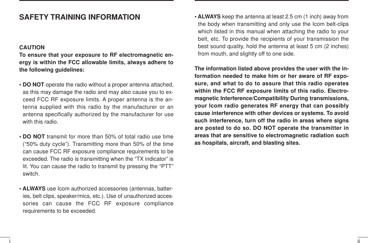
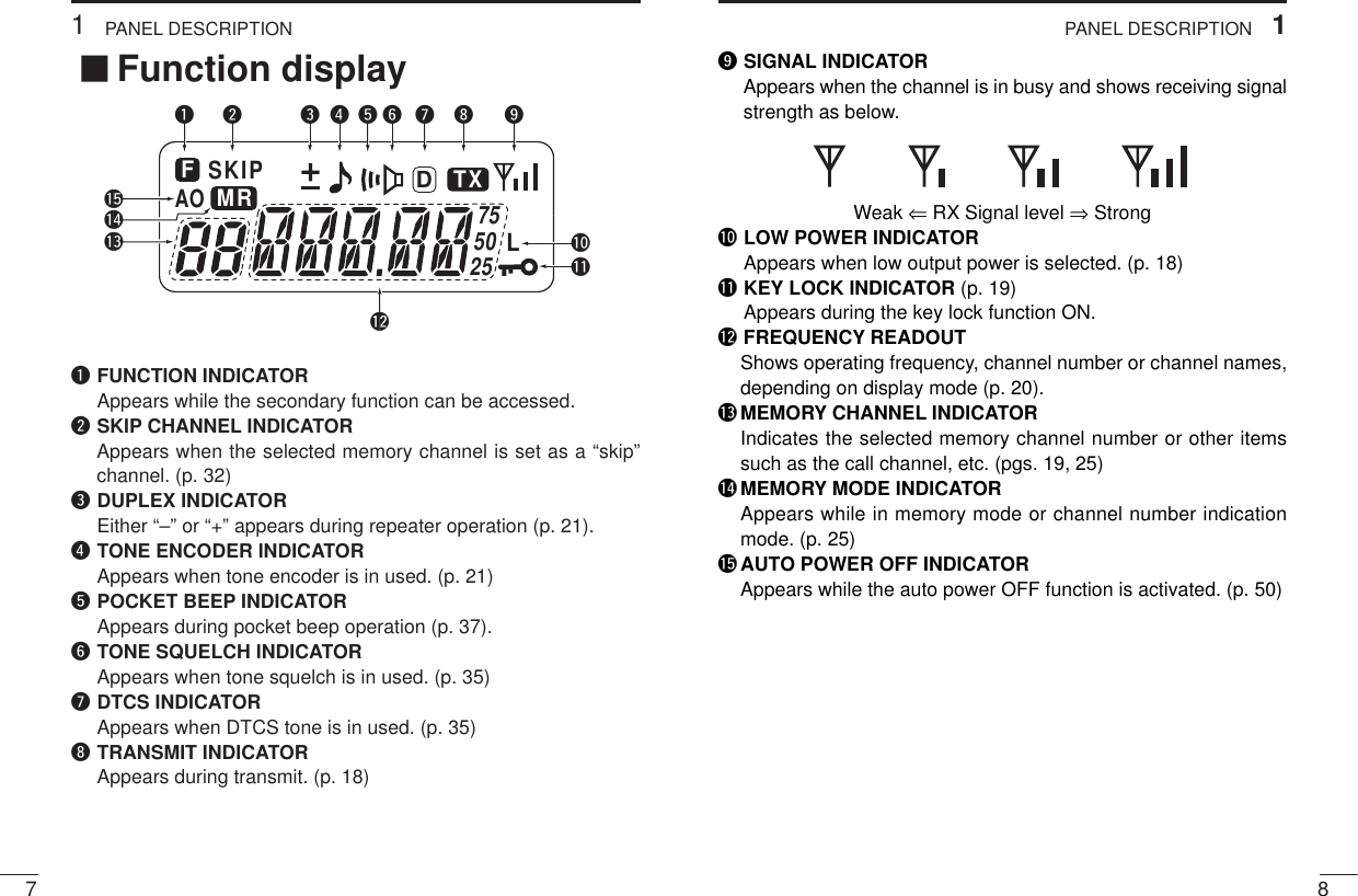
![Input digit “7” during frequency input, memory chan-nel selection, etc. (pgs. 16, 19)Input digit “8” during frequency input, memory chan-nel selection, etc. (pgs. 16, 19)Input digit “9” during frequency input, memory chan-nel selection, etc. (pgs. 16, 19)Input digit “0” during frequency input, memory chan-nel selection, etc. (pgs. 16, 19)No function.Sets the frequency even full 6-digits of frequencykeys have not been pushed. (p. 16)61PANEL DESCRIPTION51PANEL DESCRIPTIONStarts the priority watch. (p. 33)Enters to the SET MODE. (p. 46)Toggles between high and low output power. (p. 18)Enters to DTMF memory mode. (p. 28)Selects a optional pager or code squelch operation mode. (p.39)Switches key pad lock function ON and OFF when pushed for 1sec. Lock all keys, except [POWER], [PTT], [SQL], audio level adjust-ment. (p. 19)[7•PRIO][8•SET][9•HI/LO][0•DTMF-M][✱•OPTION][#•ENT]KEY FUNCTION SECONDARY FUNCTION (After [A•FUNC] is pushed)[name]DKey pad (Continued)](https://usermanual.wiki/ICOM-orporated/IC-V8/User-Guide-152120-Page-8.png)
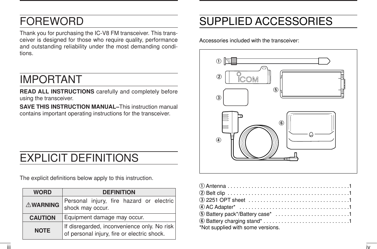
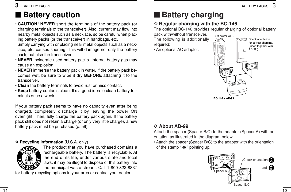
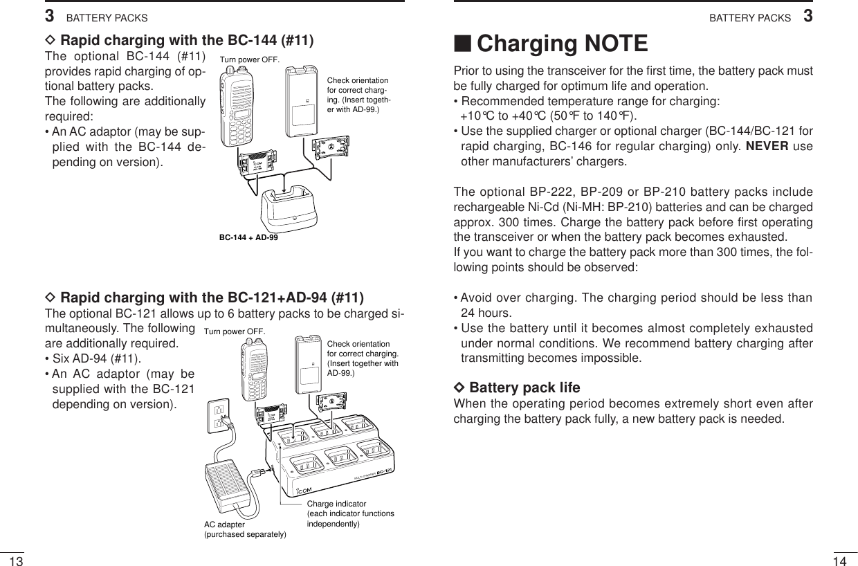
![103BATTERY PACKS92ACCESSORIES‘‘Accessory attachmentDAntennaAttach the antenna onto the transceiver as il-lustrated at right.Keep the jack cover attached when jacks arenot in use to avoid bad contacts. DBelt clip Attach the belt clip to the transceiver as illustrated below.To attach the belt-clip To release the belt-clip‘‘Battery pack replacementBefore replacing the battery pack, push [POWER] for 1 sec. to turnthe power OFF.• Push the battery releaseforward, then pull thebattery pack upwardwith the transceiver fac-ing you.DDBATTERY PACKS*1Operating periods are calculated under the following conditions;Tx : Rx : standby =5 : 5 : 90, power save function: auto setting, is activated*2Operating period depends on the alkaline cells used. (BP-208 only)yrettaB kcap egatloV yticapaCdoirepgnigrahC gnitarepO *doirep1BC-146ro441-CB 121-CB 49-DAhtiwBP-208*2AArofesacyrettaB)6R( ×enilakla6 A/N902-PB V2.7srh21srh5.1srh7.5012-PB V2.7 0561 hAm srh18.5 srh0.2srh111100mAh222-PB V2.7 006 hAm srh6.5 srh0.1srh4](https://usermanual.wiki/ICOM-orporated/IC-V8/User-Guide-152120-Page-10.png)
![■Power ONPush [POWER] for 1sec. to turnpower ON.■Setting a frequencyDVia the keypadqPush [D.CLR] to select VFO mode, if necessary.wPush 6 digit keys, starting from the 100 MHz digit, to enterthe desired frequency.• When [#•ENT]is pushed after three or more digits are entered,also the frequency is set.• When a digit is mistakenly input, push [D.CLR]to abort imputing.• “2” and “7” are acceptable for the 1 kHz digit (depending on the 10kHz digit).164BASIC OPERATION153BATTERY PACKS‘‘Battery case (optional for some versions)When using a BP-208 BATTERY CASE attached to the transceiver,install 6 AA (R6) size alkaline batteries as illustrated below.DDCAUTIONS• Use ALKALINE batteries only.• Make sure all battery cells are the same brand, type and ca-pacity.• Never mix old and new batteries.Either of the above may cause a fire hazard or damage thetransceiver. If ignored.• Never incinerate used battery cells since internal battery gasmay cause them to rupture.• Never expose a detached battery case to water.If the battery case gets wet, be sure to wipe it dry before using.MRorMRPushPush for 1 sec.](https://usermanual.wiki/ICOM-orporated/IC-V8/User-Guide-152120-Page-13.png)
![174BASIC OPERATION184BASIC OPERATION■Receive and transmitqPush [POWER] for 1sec. to turn the power ON.wAdjust volume to the desired level.eSet a frequency.When a signal is received:• Squelch opens and audio is emitted from the speaker.• Signal indicator shows the relative signal strength level.rPush [9•H/L] after pushing [A•FUNC] to toggle output power be-tween high and low.• “L” appears when low output power is selected.tPush and hold [PTT] to transmit, then speak into the micro-phone.• “TX” appears.•Do not hold the microphone too close to your mouth or speak tooloudly. This may distort the signal.yRelease [PTT] to receive ✔For your informationMonitor function:Push and hold [SQL] to listen to weak signals that do not open thesquelch.DUsing other waysVia the [YY]/[ZZ] keysEach push increments/decrements the frequency with the selectedtuning step.Using the [VOL] Rotate the [VOL] to increment/decrement the frequency with the se-lected tuning step.• This function is available when “dial” is assigned with [VOL] in INITIALSET MODE(p. 51).✔For your informationTuning steps:The transceiver has 8 tuning steps as follows:5 kHz 10 kHz 12.5 kHz 15 kHz20 kHz 25 kHz 30 kHz 50 kHz• A tuning step is selected in SET MODE. (p. 47)■Setting audio/squelch levelDTo set the audio levelRotate the [VOL] to set desired audio level while receiveing thesignal.• When no signal is received, push and hold [SQL] while settingaudio level • When “dial” is assigned [VOL], push [Y]/[Z] to adjust audio outputlevel. (p. 51)DTo set the squelch levelWhile pushing [SQL], push [Y]/[Z] to set the squelch level.• The squelch level “1” is loose squelch,“10’ is tight squelch.• When “dial” is assigned [VOL], rotate [VOL] while [SQL] is pushed.(p. 51)](https://usermanual.wiki/ICOM-orporated/IC-V8/User-Guide-152120-Page-14.png)
![204BASIC OPERATION■Selecting a memory channelqPush [C•MR] to select memory mode.•“X” appears.wPush 2 digit keys to select the de-sired memory channel (or push the[Y]/[Z] keys).• When “dial” is assigned [VOL], rotate[VOL] to select the memory channel.(p. 51)• The memory channels 0–9 are pro-ceeded by a “0.”■Selecting call channelPush [B•CALL] to select the call chan-nel.• “C” displayed instead of memorychannel number.• Push [D•CLR] or [C•MR] to return toprevious indication.■Key lock functionThe key lock function prevents accidental frequency changes andfunction activation.Push [#•ENT] for 1 sec. after push-ing [A•FUNC] to toggle the function ONand OFF.•“é” appears while the lock func-tion is activated.• [POWER], [PTT], [VOL] and [SQL] can be operated regardless ofthis setting.MRMRSKIPAOLMRFTX755025D194BASIC OPERATIONMR■Display type The transceiver has 3 display types to match your operating style.The display type is selected in the INITIAL SET MODE(p. 51).Frequency indication type is used basicamateur radio operation.Channel indication type is used to sim-plify operation. In this mode only pre-programmed memory channel numbersare displayed only. VFO mode cannot be selected.• When the channel indication type is selected, the following functionscan only be performed.- Scan function (p. 30)- Output power setting (p. 18)- DTMF memory function (p. 28)- Key lock function (p. 19)- Scan pause timer setting, function key timer setting and LCDbacklight setting in SET MODE(p. 47)Channel name indication type is used tosimplify operation same as above. Inthis mode pre-programmed memorychannel names are displayed. VFO mode selectable.• Programmed frequency is indicated when the channel name is notpre-programmed in the selected memory channel.• Push and hold [SQL] to displayed operating frequency.MRMRUSINGINITIAL SET MODEMR](https://usermanual.wiki/ICOM-orporated/IC-V8/User-Guide-152120-Page-15.png)
![215REPEATER OPERATION225REPEATER OPERATION■Offset frequencyWhen communicating through a repeater, the transmit frequency isshifted from the receive frequency by an amount determined by theoffset frequency.qPush [8•SET] after pushing [A•FUNC]to enter SET MODE.wPush [Y]/[Z] several times until “±”and offset frequency appear.eRotate [VOL] to select the desired offset frequency.• Selectable steps are the same as the pre-set tuning steps.• The unit of displayed offset frequency is “MHz.”rPush [#•ENT] to fix the offset frequency and exit SET MODE.■Subaudible tonesSome repeaters require subaudible tones to be accessed. Sub-audible tones are superimposed over your normal signal and mustbe set in advance.qPush [8•SET] after pushing [A•FUNC]to enter SET MODE.wPush [Y]/[Z] one or more times until“rt” appears.eRotate [VOL] to select the desired subaudible tone.rPush [#•ENT] to enter the selected tone and exit set mode.USINGSET MODESKIPAOLMMRFTX755025Available subaudible tone frequencies (unit: Hz)67.0 79.7 94.8 110.9 131.8 156.7 171.3 186.2 203.5 229.169.3 82.5 97.4 114.8 136.5 159.8 173.8 189.9 206.5 233.671.9 85.4 100.0 118.8 141.3 162.2 177.3 192.8 210.7 241.874.4 88.5 103.5 123.0 146.2 165.5 179.9 196.6 218.1 250.377.0 91.5 107.2 127.3 151.4 167.9 183.5 199.5 225.7 254.1USINGSET MODESKIPAOLMMRFTX755025D■GeneralWhen using a repeater, the transmit frequency is shifted from thereceive frequency by the offset frequency. It is convenient to pro-gram repeater information into memory channels.qSet the receive frequency (repeater output frequency).wPush [4•DUP] after pushing [A•FUNC] several times to select “–” or“+.”• “–” indicates the transmit frequency is shifted down; “+” indicatesthe transmit frequency is shifted up.• Flashing “–” or “+” indicates the reversed duplex mode is selectedin SET MODE(p. 46).• When the auto repeater function is in used (USA version only) thisselection and step eare not necessary. (p. 24)ePush [1•TONE] after pushing [A•FUNC] to activate the subaudibletone encoder, according to repeater requirements.• “ ” appears.• Select the desired sub audible tone frequency, if necessary. (p. 22)rPush and hold [PTT] to transmit.• The displayed frequency automatically changes to the transmit fre-quency (repeater input frequency).• If “OFF” appears, check the offset frequency and direction.tRelease [PTT] to receive.yPush and hold [SQL] to check whether the other station’s trans-mit signal can be directly received or not.About reversed duplex modeWhen the reversed duplex mode is selected, the receive fre-quencies shifts. Each receive and transmit frequency are shownin the table below with the follow conditions; entered freq. : 145.00MHz, duplex direction : – (negative), frequency offset : 0.6 MHzReversed OFF ON Rx frequency 145.30 MHz 144.70 MHzTx frequency 144.70 MHz 145.30 MHz](https://usermanual.wiki/ICOM-orporated/IC-V8/User-Guide-152120-Page-16.png)
![245REPEATER OPERATION235REPEATER OPERATION■Auto repeaterfunction (USA version only)The USA version automatically activates the repeater settings (du-plex, ON/OFF, duplex direction, tone encoder ON/OFF) when theoperating frequency falls within or outside of the general repeateroutput frequency range. The offset and repeater tone frequenciesare not changed by the auto repeater function, reset these fre-quencies, if necessary.qWhile pushing [Y]+[Z], turn the power ON to enter INITIAL SETMODE.wPush [Y]/[Z] several times until“RPt.” appears.eRotate [VOL] to select the desiredcondition.• “OF”—the auto repeater function isturned OFF;“R1”—the auto repeater function acti-vates for duplex only;“R2”—the auto repeater function acti-vates for duplex and tone.rPush [#•ENT] to exit INITIAL SETMODE.USINGINITIAL SET MODEFrequency range and offset directionFREQUENCY RANGE DUPLEX DIRECTION145.200–145.495 MHz “–” appears146.610–146.995 MHz147.000–147.395 MHz “+” appearsSKIPAOLMMRFTX755025DSKIPAOLMMRFTX755025DSKIPAOLMMRFTX755025D✔ConvenientTone scan function: When you don’t know the subaudible toneused for a repeater, the tone scan is convenient for detecting thetone frequency.Push [3•T.SCAN] after pushing [A•FUNC] to start the tone scan.• Push [D•CLR] to cancel the scan.• When the wanted tone frequency is detected, the scan pauses.DDTone informationSome repeaters require a tone to be accessed. DTMF TONESWhile pushing [PTT], push the desired DTMF keys (0–9, A–F) totransmit DTMF tones.• The transceiver has 5 DTMF memory channels (p. 28).1750 Hz TONEWhile pushing [PTT], push [Y] or [Z] for 1 to 2 sec. to transmits1750 Hz tone signal.](https://usermanual.wiki/ICOM-orporated/IC-V8/User-Guide-152120-Page-17.png)
![256MEMORY PROGRAMMING266MEMORY PROGRAMMING■Channel name programming qSelect a channel name indication type in INITIAL SET MODE(pgs. 20, 51).wPush [C•MR] to select memory mode, if necessary.ePush [8•SET] after pushing [A•FUNC] to enter to channel nameprogramming mode.• A currently editing character is flashed.tRotate [VOL] to select a character.yPush [Y] to move to the right, [Z] to move to the left.• Up to 5-digit channel names can be programmed.• Usable character are; A–Z, 0–9, ”space“, +, –, =, ✱, /, [, and ].uPush [#•ENT] to fix and exit channel name programmingmode.■Memory transferringMemory (call) channel contents can be transfer to VFO or to an-other memory channel.DMemory/call ➾VFOqSelect the memory (call) channel to be transferred:Push [C•MR] ([B•CALL]) to select memory (call) mode.Push [Y]/[Z] to select the memory channel.• When “dial” is assigned [VOL], rotate [VOL] to select the memorychannel. (p. 51)wPush [C•MR] for 1 sec. after pushing [A•FUNC] to transfer the se-lected memory contents to the VFO.• VFO mode is selected automatically.■GeneralThe transceiver has 100 memory channels (plus 3 pairs of scanedges and 1 call channels) for storage of often-used frequencies.DMemory channel contentsThe following information can be programmed into memory:• Operating frequency• Duplex direction (+ or –) with an offset frequency (pgs. 21, 22)• Subaudible tone encoder or tone squelch ON/OFF (pgs. 21, 35)• Subaudible tone and tone squelch frequencies (pgs. 22, 36)• Skip information* (p. 32)*Except for scan edge channels.■Programming the memory/callchannelsqPush [D•CLR] to select VFO mode, if necessary.wSet the desired frequency.eSet other informations such as tone, duplex, etc. as desired.rPush [C•MR] for 1 sec. (until emits 3 beeps) after pushing[A•FUNC] to program the information into the displayed memorychannel and return to VFO• Continue to hold [C•MR] down for 1sec. after 3 beeps emission, to incre-ment displayed memory channelnumber.MR](https://usermanual.wiki/ICOM-orporated/IC-V8/User-Guide-152120-Page-18.png)
![276MEMORY PROGRAMMING287DTMF MEMORY■Programming a DTMF codeThe transceiver has 5 DTMF memory channels (d0 to d4) forstorage of often-used DTMF codes of up to 24 digits.qPush [0•DTMF-M] after pushing[A•FUNC] to enter DTMF memory.• One of “d0” to “d4” appears.wRotate [VOL] to select the desiredchannel.ePush [0•DTMF-M] for 1 sec. afterpushing [A•FUNC] to enter DTMFprogramming mode.• “_ _ _ _ _” appears.• Programmed memories can be cleared in this way.rPush the digit keys, [A•FUNC], [B•CALL], [C•MR], [D•CLR], [✱•OP-TION] and [#•ENT] to enter the desired DTMF code.• A maximum of 24 digits can be input.•[✱•OPTION] enters as “E”, [#•ENT] enters as “F.”• If a digit is mistakenly input, push [SQL] or [PTT] momentarilythen repeat from step q.tPush [SQL] or [PTT] to input the digits and exit DTMF pro-gramming mode.• Programmed DTMF codes sound when [SQL] is pushed to exit.MRMRDMemory/call ➾call/memoryqSelect the memory (call) channel to be transferred:Push [C•MR] ([B•CALL]) to select memory (call) mode.Push [Y]/[Z] to select the memory channel.• When “dial” is assigned [VOL], rotate [VOL] to select the memorychannel. (p. 51)wPush [C•MR] momentarily after pushing [A•FUNC].• “--” and “X” flashes.ePush [Y]/[Z] to select the target memory.• When “dial” is assigned [VOL], rotate [VOL] to select the memorychannel. (p. 51)rPush [C•MR] for 1 sec after pushing [A•FUNC].• Memory mode is selected and the contents are transferred tothe target memory.DClearing a memoryqPush [C•MR] after pushing [A•FUNC] to enter memory transfermode.•“X” and a memory channel number flash.wPush [Y]/[Z] to select the memory channel to be cleared.• When “dial” is assigned [VOL], rotate [VOL] to select the memorychannel. (p. 51)• The call channel cannot be cleared.ePush [C•MR] after pushing [A•FUNC] momentarily, then push[C•MR] for 1 sec after pushing [A•FUNC] again.• Perform this operation within 1.5 sec. • The contents of the selected memory are cleared.rPush [D•CLR] to return to regular operation.](https://usermanual.wiki/ICOM-orporated/IC-V8/User-Guide-152120-Page-19.png)
![297DTMF MEMORY308SCAN OPERATIONPROGRAMMED SCANMEMORY (SKIP) SCANMch 0 Mch 6Mch 1 Mch 3Mch 2 Mch 4 Mch 5Mch 7Mch 99 Mch 10 Mch 9 Mch 8ScanScan edgesPRIORITY WATCHMch 3Priority memory channel scan Priority channel50 msec.VFO frequency 145.20 MHz5 sec.Mch 3Mch 5Mch 1Mch 2 Mch 4Mch 6SKIPMch 9950 msec.Memory scanPriority channelPriority memory channel watch VFO frequency145.20 MHz5 sec.SKIPSKIPBand edge Band edgeJump1A2A3A1b2b3b■Scan types■Transmitting a DTMF codeDUsing a DTMF memory channelqPush [0•DTMF-M] after pushing [A•FUNC] to enter DTMF memory.wRotate [VOL] to select the desired channel.rPush [SQL] or [PTT] to exit DTMF memory mode.tWhile pushing [PTT], push [SQL] to transmit the selected DTMFmemory.• After the DTMF code is transmitted, returns to receive automati-cally.DManual DTMF code transmissionqWhile pushing [PTT], push digit keys, A–F to transmit aDTMF code manually.• Once DTMF code key is pushed, the transmission is kept for 1 sec.after release the key even [PTT] is released.■DTMF transmission speedWhen slow DTMF transmission speeds are required with DTMFmemory transmission (as for some repeaters), the transceiver’s rateof DTMF transmission can be adjusted.qWhile pushing [Y] and [Z], turn thepower on to enter INITIAL SET MODE.wPush [Y]/[Z] several times until “dtd”appears.eRotate [VOL] to select the desiredDTMF transmission speed.• Four speeds are available: “1” (100msec. intervals) is the fastest; “5” (500msec. intervals) is the slowest.rPush [#•ENT] to exit INITIAL SET MODE.USINGINITIAL SET MODEMRMR](https://usermanual.wiki/ICOM-orporated/IC-V8/User-Guide-152120-Page-20.png)
![328SCAN OPERATION318SCAN OPERATION■Programmed scanProgrammed scan repeatedly scans between two user-pro-grammed frequencies (memory channels “1A–3A” and “1b–3b”) orscans between upper and lower band edges. This scan is usefulfor checking for signals within a specific frequency range such asrepeater output frequencies, etc.qPush [D•CLR] to select VFO mode, if necessary.wPush [5•SCAN] after pushing [A•FUNC] to start the scan, then aselected scan edge appears as “P1”, “P2”, “P3” or “AL.”• To change scan edge, push [8•SET] after pushing [A•FUNC] severaltimes until desired scan edge is appeared.• “AL” for full scan, “P1”, “P2” and “P3” for programmed scan be-tween the programmed scan edge channels as “1A”–“1b”,“2A”–“2b” and “3A”–“3b”.• To change the scan direction, push [Y] or [Z].• When “dial” is assigned [VOL], rotate [VOL] to change the scan di-rection. (p. 51)ePush [D•CLR] to stop the scan.NOTE: Scan edges, 1A–3A/1b–3b, must be programmed in ad-vance. (Program them in the same manner as regular memorychannels. (p. 25))If the same frequencies are programmed into the scan edges,programmed scan will not proceed.■Memory (skip) scanMemory scan repeatedly scans all programmed memory chan-nels, except those set as skip channels.qPush [C•MR] to select memory mode, if necessary.•“X” appears.wPush [5•SCAN] after pushing [A•FUNC] to start the scan.• To change the scan direction, push [Y] or [Z].• When “dial” is assigned [VOL], rotate [VOL] to change the scan di-rection. (p. 51)ePush [D•CLR] to stop the scan.DSetting skip channelsIn order to speed up the scan interval, you can set memorychannels you don’t wish to scan as skip channels.qPush [C•MR] to select memory mode, if necessary.•“X” appears.wSelect a memory channel to set as a skip channel.ePush [6•SKIP] after pushing [A•FUNC] to toggle the skip settingON and OFF.• “SKIP” appears when the channels is set as a skip channel.](https://usermanual.wiki/ICOM-orporated/IC-V8/User-Guide-152120-Page-21.png)
![348SCAN OPERATION338SCAN OPERATION■Priority watchPriority watch checks for signals on “priority channels” while oper-ating on a VFO frequency.DMemory or call channel watchWhile operating on a VFO frequency, memory or call channel watchmonitors for signals in the selected memory or call channel every 5 sec.qSelect the desired memory channel or the call channel.wPush [D•CLR] to select VFO mode.ePush [7•PRIO] after pushing [A•FUNC] to start watching.• VFO is displayed, then the decimal point “.”, on the frequency read-out flashes.• The priority channel is monitored every 5 sec. • When the signal is detected on the priority channel, the watchingis paused according to setting of scan resume condition.rPush [D•CLR] to stop watching.DMemory scan watchWhile operating on a VFO frequency or the call channel, memoryscan watch monitors for signals in each memory channels in se-quence every 5 sec.q Push [C•MR] to select memory mode, if necessary.•“X” appears.wPush [5•SCAN] after pushing [A•FUNC] to start the memory scan.ePush [7•PRIO] after pushing [A•FUNC] to start the watching.• VFO is displayed, then the decimal point “.”, on the frequency read-out is flashed.• When the signal is detected on priority channel, the watching ispaused according to setting of scan resume condition.rPush [D•CLR] to stop the watching.■Scan resumeconditionWhen a signal is received duringscanning, the scan resume condi-tion determines what action thetransceiver takes. The transceiverhas 2 scan resume conditions avail-able as illustrated at right. UseSETMODEto select the one which bestsuits your needs.qPush [8•SET] after pushing [A•FUNC] to enter SET MODE.wPush [Y]/[Z] several times until “SCP” or “SCt” appears.eRotate [VOL] to select the desired scan resume condition.•Pause scan: when receiving a signal,scan pauses on the signal until it ap-pears. Resumes after 2 sec. from thesignal disappears. Timer scan: when receiving a signal,scan pauses on the signal for 5 sec., 10sec. or 15 sec. then resumes.rPush [#•ENT] to set and exit SET MODE.PausescanReceivinga signalTimerscan5, 10 or 15 sec. 2 sec.Pause scanTimer scanSKIPAOLMMRFTX755025DDSKIPAOLMMRFTX755025DUSINGSET MODE](https://usermanual.wiki/ICOM-orporated/IC-V8/User-Guide-152120-Page-22.png)
![369SUBAUDIBLE TONESDSetting subaudible tones for tone squelch operationSeparate tone frequencies can be set for tone squelch operationthan repeater operation (the same range of tones is available— seebelow). As the repeater tones, these are set in set mode.qSelect VFO or memory channel.wPush [A•FUNC] + [8•SET] to enter set mode.ePush [∫] or [√] several times until “Ct” ap-pears when selecting CTCSS, or “dt” ap-pears when selecting DTCS.• “ ” flashes when selecting CTCSS, or “ ” flashes when selecting DTCS.rRotate [VOL] to select the desired subaudible tone.tPush [#•ENT] to program the selected tone and exit setmode.When set mode is selected from memory mode.yPush [C•MR] for 1 sec. after [A•FUNC] is pushed. • Emits 3 beeps. • VFO mode is selected automatically. uPush [C•MR] for 1 sec. after [A•FUNC] is pushed. • Emits 3 beeps. The step yand uare necessary when overwriting the memorycontents for permanently. Therefore, the set tone frequency is usedfor temporarily operation only, these steps are not necessary. •Subaudible CTCSS tone frequency listD67.069.371.974.477.079.782.585.488.591.594.897.4100.0103.5107.2110.9114.8118.8123.0127.3131.8136.5141.3146.2151.4156.7159.8162.2165.5167.9171.3173.8177.3179.9183.5186.2189.9192.8196.6199.5203.5206.5210.7218.1225.7229.1233.6241.8250.3254.1MRFTXMRFDTX35SUBAUDIBLE TONES9‘‘Tone squelchDOperationThe tone squelch opens only when receiving a signal containing amatching subaudible tone. You can silently wait for calls from groupmembers using the same tone.qSet the operating frequency.• Set the AF and squelch to the desired level as the normal operation.wSet the desired subaudible tone in the set mode.• See right for programming.ePush [1•TONE] after [A•FUNC] is pushed.• Repeat several times until “ ” appears when selecting CTCSS, or“ ” appears when selecting DTCS.rWhen the received signal includes a matching tone, squelchopens and the signal can be heard.• When the received signal’s tone does not match, tone squelchdoes not open, however, the S-indicator shows signal strength.• To open the squelch manually, push and hold [SQL].tOperate the transceiver in the normal way.yTo cancel the tone squelch, push [1•TONE] after [A•FUNC] ispushed.• Repeat several times until “ ” or “ ” disappear.NOTE: The transceiver has 50 tone frequencies and conse-quently their spacing is narrow compared to units having 38tones. Therefore, some tone frequencies may receive interfer-ence from adjacent tone frequencies.To prevent interference from adjacent tone frequencies, use thefrequencies as following table is recommended.DD67.069.371.974.488.591.594.897.4114.8118.8123.0127.3151.4156.7162.2167.9203.5210.7218.1225.777.079.782.585.4100.0103.5107.2110.9131.8136.5141.3146.2173.8179.9186.2192.8233.6241.8250.3• Recommended tone frequencies](https://usermanual.wiki/ICOM-orporated/IC-V8/User-Guide-152120-Page-23.png)
![389SUBAUDIBLE TONES‘‘Tone scanBy monitoring a signal that is being operated with repeater, pocketbeep or tone squelch function, you can determine the tone fre-quency necessary to access a repeater or open a squelch.qSet the frequency to be checked for a tone frequency or code.wPush [1•TONE] after [A•FUNC] is pushed. • Repeat several times to select the tone condition or type to bescanned. (One of “ ”, “ ” or “ ” appears)• The tone scan can be operated even the tone condition or type isselected.ePush [3•T.SCAN] after [A•FUNC] is pushed to starts the tone scan.• To change the scanning direction, push [∫] or [√]. rWhen the CTCSS tone frequency or DTCS code is matched, thesquelch opens and the tone frequency or code is temporarilyprogrammed into the selected mode such as memory or callchannel.• The tone scan pauses when a CTCSS tone frequency or 3-digitDTCS code is detected.• The decoded CTCSS tone frequency or 3-digit DTCS code is usedfor the tone encoder or tone encoder/decoder depending on theselected tone condition or type in step w.- No indication : Cannot be used for operation.- “ ” : CTCSS tone encoder- “ ” : CTCSS tone encoder/decoder- “ ” : DTCS tone encoder/decodertPush [D•CLR] to stop the scan.DDMRFTXMRFDTXSUBAUDIBLE TONES937‘‘Pocket beep operationThis function uses subaudible tones for calling and can be used asa “common pager” to inform you that someone has called when youwere away from the transceiver.DWaiting for a call from a specific stationqSet the operating frequency.wSet the desired CTCSS tone frequency or DTCS code in the setmode.• See p. 36 for programming details.ePush [1•TONE] after [A•FUNC] is pushed.• Repeat several times until “ ” appears when CTCSS, or “ ” ap-pears when DTCS is selected.rPush [2•P.BEEP] after [A•FUNC] is pushed toactivates the pocket beep function.• “ ” appears.tWhen a signal with the matched tone is re-ceived, the transceiver emits beep tonesand flashes “ .”• Beep tones sound for 30 sec. and “”flashes. To stop the beeps manually,push any key. “ ” continues blinking untilstep yis operated.yPush [PTT] to answer.• “” disappears and cancels the pocket beep function automatically. DMRFDTX“ ” appearsMRFDTX](https://usermanual.wiki/ICOM-orporated/IC-V8/User-Guide-152120-Page-24.png)
![4010PAGER/CODE SQUELCH‘‘Code programmingDDBefore programmingThe pager and code squelch functions require ID codes and agroup code. These codes are 3-digit DTMF codes and must writteninto the code channels before operation.qDecide the ID code of each transceiver and a group code foryour group.wDecide whether you want to return to normal operation or codesquelch operation after a connection is made.eProgram the ID code, group code and transmit codes (other sta-tion’s codes) as below.DDCode channel assignment*Channel CP automatically memorized an ID code when receiving apager call. The contents in channel CP cannot be changed manually.Optional UT-108 requiredID OR CODE CHANNEL “RECEIVE ACCEPT” OR GROUP CODE NUMBER “RECEIVE INHIBIT”Your ID code 0 “Receive accept” onlyOther parties’ 1–6 “Receive inhibit” should be ID codeprogrammed in each channel.Group code One of 1–6 “Receive accept” must be programmed.Memory space* P “Receive inhibit” only.3910 PAGER/CODE SQUELCH‘‘Pager functionThis function uses DTMF codes for paging and can be used as a“message pager” to confirm you of a caller’s identification evenwhen you leave the transceiver temporarily unattended.Optional UT-108 requiredPager selective code (push [PTT])Beep BeepBeep Answer back (manual)Beep BeepBeep Set both transceivers to eithercode squelch or non-coded operationCommunication](https://usermanual.wiki/ICOM-orporated/IC-V8/User-Guide-152120-Page-25.png)
![4210PAGER/CODE SQUELCH•Receive accept/receive inhibit➥“Receive accept” (“SKIP” indicator does not appear) acceptspager calls when the transceiver receives a signal with a codethe same as that in the code channel.➥“Receive inhibit” (“SKIP” indicator appears) rejects calls evenwhen the transceiver receives a code the same as that in thecode channel. Transmit codes should therefore be programmedfor “receive inhibit,” otherwise the transceiver will not reject un-necessary calls.•Pager/code squelch operation during channel indicationTo use these functions in channel indication, the pager/codesquelch setting must be programmed with other memory contentsbefore selecting channel number indication.4110PAGER/CODE SQUELCHDDCode programmingAn ID code MUST be programmed into code channel C0. Up to 6transmit codes are programmable into code channels, C1 to C6, ifrequired.qPush [✱•OPTION] after [A•FUNC] is pushed.• Pager mode is selected.• 100 MHz digit shows “P.” wPush [8•SET] after [A•FUNC] is pushed.• One of “CP” or “C0” to “C6” flashes.• “C0” is the ID code and “C1” to “C6” aretransmit code.eRotate [VOL] to select code channel C0.• A different ID code must be programmed into each transceiver.rEnter the desired 3-digit ID code via thekeypad.tRotate [VOL] to select a transmit codechannel from C1 to C6. yEnter the desired 3-digit transmit code viathe keypad.uPush [6•SKIP] after [A•FUNC] is pushed toset the channel for “receive inhibit” or “re-ceive accept.”• When “receive inhibit” is set, “SKIP” ap-pears as at right.• Code channel C0 cannot be set as “receive inhibit.”• See the following table for “receive accept” and “receive inhibit” de-tails.iRepeat steps tand yto set additional transmit code channels,if desired.oPush [#•ENT] or [PTT] to exit code set mode.MRFTXMRFTXMRFTXMRFTXSKIPMRFTX](https://usermanual.wiki/ICOM-orporated/IC-V8/User-Guide-152120-Page-26.png)
![4410PAGER/CODE SQUELCHDWaiting for call from a specific stationqSet the operating frequency.wPush [✱•OPTION] after [A•FUNC] is pushed.• 100 MHz digit shows “P.” eWait for a call.• When receiving a call, the caller’s ID or group code appears asshown below.• DO NOT push any digit keys while code channels C0 to C6 are dis-played, or code channel contents are changed.rPush [PTT] to send an answer back call and display the operat-ing frequency.tAfter confirming a connection push [✱•OPTION] after [A•FUNC] ispushed to select code squelch operation, or repeat previous keyoperation again to select non-selective calling system.•PERSONS CALLSThis display appears when you are calledwith your ID code and the calling station’s IDcode is 123.•GROUP CALLSThis display appears when you are calledwith the group code, 888, and 888 has beenprogrammed into code channel C6.•ERROR INFORMATIONWhen the transceiver receives an incompletesignal, “E” and previously received code ap-pear.SKIPMRFTXCP and flash.MRFTXCode channelMRFTXPreviously receivedcode.4310PAGER/CODE SQUELCH‘‘Pager operationDCalling a specific stationqProgram the needed code channel in advance (p. 41).wSet the operating frequency.• Set the AF and squelch to the desired level as the normal operation.ePush [✱•OPTION] after [A•FUNC] is pushed.• Pager mode is selected.• 100 MHz digit shows “P.” rSelect the desired transmit code channel:➥Push [8•SET] after [A•FUNC] is pushed.➥Rotate [VOL] to select the desired code channel.➥Push [#•ENT] to return to previous condition.tPush [PTT] to transmit the pager code.yWait for an answer back.• When the transceiver receives an answer back code, the functiondisplay shows the other member’s ID or group code.uAfter confirming a connection push [✱•OPTION] after [A•FUNC] ispushed to select code squelch operation, or repeat previous keyoperation again to select non-selective calling system.• DO NOT push any digit keys while code channels C0 to C6 are dis-played, or code channel contents are changed.iCommunicate with the other party as normal: push [PTT] totransmit; release to receive.Optional UT-108 requiredMRFTX](https://usermanual.wiki/ICOM-orporated/IC-V8/User-Guide-152120-Page-27.png)
![4611OTHER FUNCTIONS‘‘Set modeDDSet mode enteringqPush [8•SET] after [A•FUNC] is pushed.wPush [∫] or [√] to select item.eRotate [VOL] to select condition/value.• To exit set mode, push [#•ENT].DDRepeater tone frequencySelects tone encoder frequency for accessinga repeater, etc. from one of 50 available fre-quencies.• 67.0–254.1 Hz (50 tones): 88.5 Hz (default)DDTone squelch frequencySelects frequency for tone squelch or pocketbeep operation from one of 50 available fre-quencies.• 67.0–254.1 Hz (50 tones): 88.5 Hz (default)DDDTCS code Selects DTCS encoder/decoder code with po-larity (N: normal/I: inverse) from one of 208available codes.• 023N/I–754N/I: 023N (default)DDOffset frequencySets the offset frequency for duplex (repeater)operation within 0–20.00 MHz range.DDReverse functionTurns the reverse function ON and OFF.• Default: OFFMRFTXMRFTXMRFDTXMRFTXMRFTX4510PAGER/CODE SQUELCH‘‘Code squelchCode squelch provides communications with quiet standby sinceyou will only receive calls from stations which know your ID orgroup code. Each push of [PTT] sends a 3-digit code in order toopen the receiving station’s code squelch prior to voice transmis-sion.qSet the operating frequency.• Set the AF and squelch to the desired level as the normal operation.wPush [✱•OPTION] after [A•FUNC] is pushed.• Repeat several times, if necessary.• Code squelch mode is selected.• 100 MHz digit shows “C.” eSelect the desired transmit code channel:➥Push [8•SET] after [A•FUNC] is pushed.➥Rotate [VOL] to select the desired code channel.➥Push [#•ENT] to exit code set mode.rOperate the transceiver in the normal way (push [PTT] to trans-mit; release [PTT] to receive).tTo cancel the code squelch, push [✱•OPTION] after [A•FUNC] ispushed.• 100 MHz digit shows “1” when the function is cancelled.Optional UT-108 requiredMRFTX](https://usermanual.wiki/ICOM-orporated/IC-V8/User-Guide-152120-Page-28.png)
![4811OTHER FUNCTIONSDDTransmission permissionTurns transmission permission ON and OFF.This function can be set for each memory andcall channel, independently.• tX .ON: Transmission is permitted. (default)• tX .OF: Transmission is inhibited.DDPager/Code squelch channelPrograms 3-digit ID code in channel “C0”and individual or group call code in channel“C1” to “C6” for the pager and code squelchfunctions. See p. 41 for programming details.*This item appears only when the optional UT-108 is installed and pageror code squelch function is activated.Optional UT-108 requiredMRFTXMRFTX4711 OTHER FUNCTIONSDDTuning step Selects tuning step from 5, 10, 12.5, 15, 20,25 , 30 and 50 kHz. DDScan pause timerSelects the scan pause time from SCt.5,SCt.10, SCt.15 and SCP. 2. When receivingsignals, the scan pauses according to thescan pause time.• SCt. 5/10/15 : Scan pauses for 5/10/15 sec.(default: SCt.15)• SCP. 2 : Scan pauses until signal dis-appears. Resumes after 2 sec. from signal disap-pearing.DDFunction key timerSelects [A•FUNC] effect timer from F0.At,F1.At, F2.At, F3.At and F .m.• F0.At : “ ” disappears immediately after(default) secondary function is operated. • F1/2/3.At : “ ” disappears after 1/2/3 sec.from secondary function is oper-ated. • F .m : “ ” appears until [A•FUNC] is pushed again.DDLCD backlightSelects LCD backlight lighting condition fromauto, ON and OFF.• LIG.At : Lights when any keys except[PTT] is pushed. (default)• LIG.ON : Lights continuously during the transceiver poweredON.• LIG.OF : Never lights.FFFMRFTXMRFTXMRFTXMRFTXMRFTXMRFTX](https://usermanual.wiki/ICOM-orporated/IC-V8/User-Guide-152120-Page-29.png)
![5011OTHER FUNCTIONSDDAuto repeaterThe auto repeater function automatically turnsON or OFF the duplex operation with speci-fied shift direction and tone encoder, when theoperating frequency falls within or outside of145.200–145.495, 146.610–146.995 and147.000–147.395 MHz range. The offset andrepeater tone frequencies are not changed bythe auto repeater function, reset these frequencies, if necessary.• RPt.OF : The auto repeater function is turned OFF. • RPt.R1 : Activates for duplex only. (default)• RPt.R2 : Activates for duplex and tone.DDAuto power-off The transceiver can be set to automaticallyturn OFF after a specified period with beep inwhich no key operations are performed.• 30 min., 1 hour, 2 hours and OFF (default)can be specified. The specified periods is re-tained even when the transceiver is turnedOFF by the auto power-off function. To can-cel the function, select “POF.OF” in this set mode.DDRepeater lock-outSelects lockout type from repeater, busy andOFF.• RLO.RP : The repeater lockout is turned ON. • RLO.bu : The busy lockout is turned ON.• RLO.OF: Any lockout is not activated. (default)U.S.A. version onlyMRFTXAOMRFTXMRFTXMRFTXMRFTXMRFTX4911 OTHER FUNCTIONS‘‘Initial set modeThe initial set mode is accessed at power on and allows you to setseldom-changed settings. In this way, you can “customize” trans-ceiver operations to suit your preference and operating style. DDEntering initial set mode qTurn power on while [∫] and [√] are pushed.wPush [∫] or [√] to select item.eRotate [VOL] to select condition/value.• To exit set mode, push [#•ENT].DDKey-touch beepTurns key-touch beep emission ON and OFF.• Default: ONDDTime-out timerTo prevent accidental prolonged transmission,etc., the transceiver has a time-out timer. Thisfunction cuts a transmission OFF after 1–30min. of continuous transmission. This timercan be cancelled.• tOt.OF : The time-out timer is turned OFF. (default)• tOt. 1–30 : The transmission cut OFF after the set period elapses.ATPOWER ONMRFTXMRFTX](https://usermanual.wiki/ICOM-orporated/IC-V8/User-Guide-152120-Page-30.png)
![5211OTHER FUNCTIONSDDLCD contrastSelects LCD contrast from auto and low.• LCd.AT : Automatic (default)• LCd.LO : Low contrast DDPower saveSelects duty cycle for power save functionfrom auto, 1:32, 1:16, 1:8, 1:2 and OFF.• P–S.At : Duty cycle changes automatically.(default)• P–S.32 : 1:32 (62.5 msec. standby: 2 sec.power saved) duty cycle; • P–S.16 : 1:16 (62.5 msec. standby: 1 sec.power saved) duty cycle • P–S. 8 : 1:8 (62.5 msec. standby: 500 msec. power saved)duty cycle • P–S. 2 : 1:2 (62.5 msec. standby: 125 msec. power saved)duty cycle • P–S.OF: The power save function turned OFF.DDTuning speed accelerationThe tuning speed acceleration automaticallyspeeds up the tuning speed when pushingand holding [∫] or [√], or rotating [VOL]rapidly.*• S–S.At : The tuning speed acceleration isactivated. (default)• S–S. m : The tuning speed acceleration isnot activated. *When tuning dial is assigned with [VOL].MRFTXMRFTXMRFTXMRFTXMRFTX5111 OTHER FUNCTIONSDDSquelch delaySelects squelch delay from short and long toprevent repeated opening and closing of thesquelch during reception of the same signal.• Sqt. S: The squelch closes in short delay.(default)• Sqt. L: The squelch closes in long delay.DDDTMF speedThe rate at which DTMF memories send indi-vidual DTMF characters can be set to accom-modate operating needs.• 1: 100 msec. interval; 5.0 cps speed (default)• 2: 200 msec. interval; 2.5 cps speed • 3: 300 msec. interval; 1.6 cps speed • 5: 500 msec. interval; 1.0 cps speed (cps=characters/sec.)DDDial assignmentSelects [VOL] control action from AF volumeand tuning dial.• tOP.VO : AF volume (default)• tOP.dI : Tuning dial DDDisplay typeSelects LCD indication type from frequency,channel number and channel names.• dSP.FR : Shows frequency (default)• dSP.CH: Shows channel number*• dSP.Nm: Shows channel names*Memory channels can only be selected.MRFTXMRFTXMRFTXMRFTXMRFTXMRFTXMRFTX](https://usermanual.wiki/ICOM-orporated/IC-V8/User-Guide-152120-Page-31.png)
![5411OTHER FUNCTIONS‘‘CPU resetThe function display may occasionally display erroneous informa-tion (e.g. when first applying power). This may be caused by exter-nally by static electricity or other factors.If this problem occurs, turn power OFF. After waiting a few seconds,turn power ON again. If the problem persists, perform CPU reset-ting operation as following procedure.• Turn power on while [SQL] and [D•CLR] arepushed.CAUTION:Resetting the CPU returns to all programmedcontents to their default settings.ATPOWER ON5311 OTHER FUNCTIONSDDMic simple modeThis item turns the microphone simple modeON and OFF. Microphone simple mode isused to change the function assignments forkeys in the optional HM-75AREMOTE-CONTROLSPEAKER-MICROPHONEas below. This assign-ment is convenient for 3-channel use of sim-ple operation.• mIC.N1 : Normal 1 (default)• mIC.N2 : Normal 2• mIC.Sm : Simple modeNOTE:Turn power OFF when connecting the HM-75A to the trans-ceiver.VFO mode cannot be selected via the microphone when SIM-PLE mode is selected.Optional HM-75A requiredMRFTXMRFTXHM-75A Mode NORMAL1 NORMAL2 SIMPLEkey[A] Freq. [B•CALL][SQL] [SQL]CH Null[B] Freq. VFO/Memory VFO/Memory [B•CALL]CH Null Null[∫]Freq. Freq. Up Freq. Up MR-00CHCH Memory CH Up Memory CH Up[√]Freq. Freq. Down Freq. Down MR-01CHCH Memory CH Down Memory CH Down](https://usermanual.wiki/ICOM-orporated/IC-V8/User-Guide-152120-Page-32.png)
![5613OPTIONAL UNIT DOptional UT-108 installationqRemove the optionalconnecter access cover(named 2251 OPTsheet).•Insert a screwdriver intothe hollow of the chassis,then lift and take awaythe cover. (The covercan not be used again.)WARNING!NEVER attempt to remove the optional connector coverusing your finger nails, this may result in injury.wAttach the optional unit. Insert the connector tightly to avoid abad contact.eRemove the paper back-ing of 2251 OPT sheetsupplied as an acces-sory.rAttach the new 2251OPT sheet to the servicewindow.tProgram the necessaryinformation from thetransceivers key pads orusing the cloning soft-ware, before operation. 5512 CLONINGCloning allows you to quickly and easily transfer the programmedcontents from one transceiver to another transceiver; or, data froma PC to a transceiver using the optional CS-V8 CLONING SOFTWARE.DTransceiver-to-transceiver cloningqConnect the OPC-474 CLONING CABLEwithadaptor plugs to the [SP] jack of the master and sub trans-ceivers. • The master transceiver is used to send data to the sub transceiver.wWhile pushing [A•FUNC]+[Y], turn power ON to enter cloningmode (master transceiver only— power ON only for sub trans-ceiver).• “CLONE” appears and the transceivers enter the clone standbycondition.ePush [PTT] on the master transceiver.• “CL” appears in the master transceiver’s display and two digit num-bers show that data is being transferred to the sub transceiver.• “CL IN” appears automatically in the sub transceiver’s display andtwo digit numbers show that data is being received from the mastertransceiver.rWhen cloning is finished, turn power OFF, then ON again to exitcloning mode.DCloning using a PCPlease refer to the HELP file that comes with CS-V8 CLONINGSOFTWARE.NOTE: DO NOT push the [PTT] on the sub transceiver duringcloning. This will cause a cloning error.ATPOWER ONqwer](https://usermanual.wiki/ICOM-orporated/IC-V8/User-Guide-152120-Page-33.png)