ICOM orporated IC-V8 Amateur Scanning Transceiver User Manual IC V8
ICOM Incorporated Amateur Scanning Transceiver IC V8
Instruction Manual
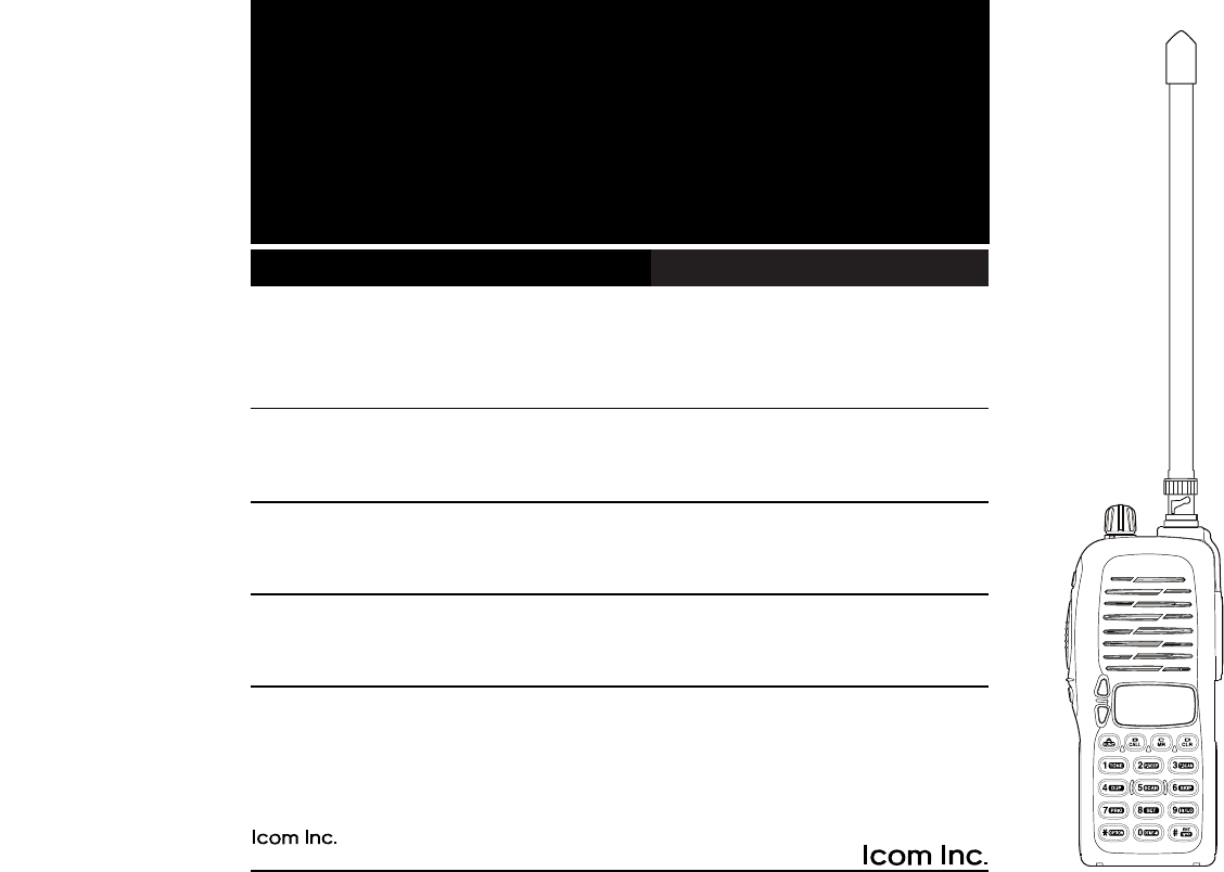
INSTRUCTION MANUAL
VHF TRANSCEIVER
iV8
This device complies with Part 15 of the FCC rules. Oper-
ation is subject to the following two conditions: (1) This de-
vice may not cause harmful interference, and (2) this
device must accept any interference received, including in-
terference that may cause undesired operation.
1-1-32 Kamiminami, Hirano-ku, Osaka 547-0003 Japan
A-6043H-1EX
Printed in Japan
© 2001 Icom Inc.
Count on us!

iii
SAFETY TRAINING INFORMATION
CAUTION
To ensure that your exposure to RF electromagnetic en-
ergy is within the FCC allowable limits, always adhere to
the following guidelines:
• DO NOT operate the radio without a proper antenna attached,
as this may damage the radio and may also cause you to ex-
ceed FCC RF exposure limits. A proper antenna is the an-
tenna supplied with this radio by the manufacturer or an
antenna specifically authorized by the manufacturer for use
with this radio.
• DO NOT transmit for more than 50% of total radio use time
(“50% duty cycle”). Transmitting more than 50% of the time
can cause FCC RF exposure compliance requirements to be
exceeded. The radio is transmitting when the “TX indicator” is
lit. You can cause the radio to transmit by pressing the “PTT”
switch.
• ALWAYS use Icom authorized accessories (antennas, batter-
ies, belt clips, speaker/mics, etc.). Use of unauthorized acces-
sories can cause the FCC RF exposure compliance
requirements to be exceeded.
• ALWAYS keep the antenna at least 2.5 cm (1 inch) away from
the body when transmitting and only use the Icom belt-clips
which listed in this manual when attaching the radio to your
belt, etc. To provide the recipients of your transmission the
best sound quality, hold the antenna at least 5 cm (2 inches)
from mouth, and slightly off to one side.
The information listed above provides the user with the in-
formation needed to make him or her aware of RF expo-
sure, and what to do to assure that this radio operates
within the FCC RF exposure limits of this radio. Electro-
magnetic Interference/Compatibility During transmissions,
your Icom radio generates RF energy that can possibly
cause interference with other devices or systems. To avoid
such interference, turn off the radio in areas where signs
are posted to do so. DO NOT operate the transmitter in
areas that are sensitive to electromagnetic radiation such
as hospitals, aircraft, and blasting sites.
iv
EXPLICIT DEFINITIONS
The explicit definitions below apply to this instruction.
iii
FOREWORD
Thank you for purchasing the IC-V8 FM transceiver. This trans-
ceiver is designed for those who require quality, performance
and outstanding reliability under the most demanding condi-
tions.
IMPORTANT
READ ALL INSTRUCTIONS carefully and completely before
using the transceiver.
SAVE THIS INSTRUCTION MANUAL–This instruction manual
contains important operating instructions for the transceiver.
WORD DEFINITION
RWARNING Personal injury, fire hazard or electric
shock may occur.
CAUTION Equipment damage may occur.
NOTE If disregarded, inconvenience only. No risk
of personal injury, fire or electric shock.
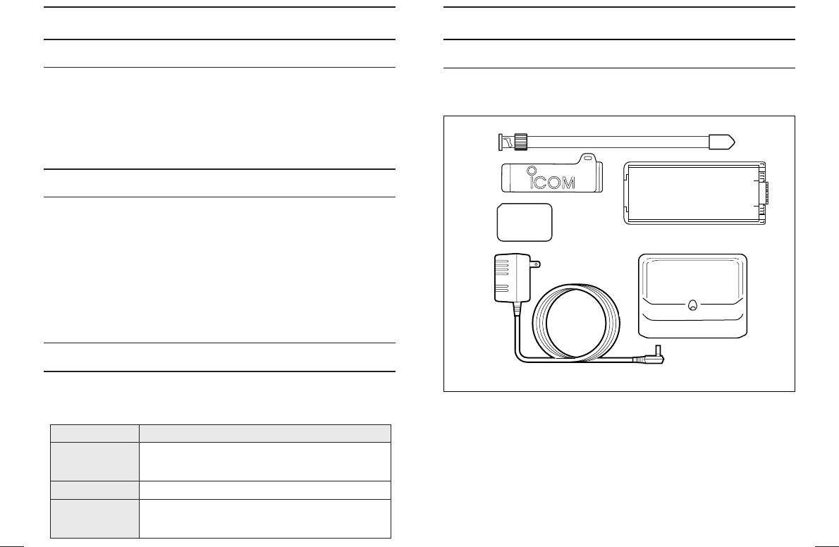
SUPPLIED ACCESSORIES
Accessories included with the transceiver:
qAntenna . . . . . . . . . . . . . . . . . . . . . . . . . . . . . . . . . . . . . . . . .1
wBelt clip . . . . . . . . . . . . . . . . . . . . . . . . . . . . . . . . . . . . . . . . .1
e2251 OPT sheet . . . . . . . . . . . . . . . . . . . . . . . . . . . . . . . . . .1
rAC Adapter* . . . . . . . . . . . . . . . . . . . . . . . . . . . . . . . . . . . . .1
tBattery pack*/Battery case* . . . . . . . . . . . . . . . . . . . . . . . . .1
yBattery charging stand* . . . . . . . . . . . . . . . . . . . . . . . . . . . . .1
*Not supplied with some versions.
w
e
q
r
y
t

viv
PRECAUTION
RWARNING! NEVER hold the transceiver so that the
antenna is very close to, or touching exposed parts of the body,
especially the face or eyes, while transmitting. The transceiver
will perform best if the microphone is 5 to 10 cm (2 to 4 in) away
from the lips and the transceiver is vertical.
RWARNING! NEVER operate the transceiver with a
headset or other audio accessories at high volume levels. Hear-
ing experts advise against continuous high volume operation. If
you experience a ringing in your ears, reduce the volume or dis-
continue use.
NEVER connect the transceiver to a power source that is DC
fused at more than 5 A. Accidental reverse connection will be
protected by this fuse, higher fuse values will not give any pro-
tection against such accidents and the transceiver will be ru-
ined.
NEVER attempt to charge alkaline or dry cell batteries. Be-
ware that external DC power connections will charge batteries
inside the battery case. This will damage not only the battery
case but also the transceiver.
DO NOT push the PTT when not actually desiring to trans-
mit.
Place unit in a secure place to avoid inadvertent use by chil-
dren.
DO NOT operate the transceiver near unshielded electrical
blasting caps or in an explosive atmosphere.
AVOID using or placing the transceiver in direct sunlight or in
areas with temperatures below –10°C (+14°F) or above +60°C
(+140°F).
The use of non-Icom battery packs/chargers may impair trans-
ceiver performance and invalidate the warranty.
Even when the transceiver power is OFF, a slight current still
flows in the circuits. Remove the battery pack or case from the
transceiver when not using it for a long time. Otherwise, the bat-
tery pack or installed Ni-Cd batteries will become exhausted.
For USA only:
Caution: Changes or modifications to this transceiver, not ex-
pressly approved by Icom Inc., could void your authority to op-
erate this transceiver under FCC regulations.

vii viii
TABLE OF CONTENTS
SAFETY TRAINING INFORMATION . . . . . . . . . . . . . . . . . . . . . . .i–ii
FOREWORD . . . . . . . . . . . . . . . . . . . . . . . . . . . . . . . . . . . . . . . . . .iii
IMPORTANT . . . . . . . . . . . . . . . . . . . . . . . . . . . . . . . . . . . . . . . . . .iii
EXPLICIT DEFINITIONS . . . . . . . . . . . . . . . . . . . . . . . . . . . . . . . . .iii
SUPPLIED ACCESSORIES . . . . . . . . . . . . . . . . . . . . . . . . . . . . . . iv
PRECAUTION . . . . . . . . . . . . . . . . . . . . . . . . . . . . . . . . . . . . . . .v–vi
TABLE OF CONTENTS . . . . . . . . . . . . . . . . . . . . . . . . . . . . . vii–viii
1 PANEL DESCRIPTION . . . . . . . . . . . . . . . . . . . . . . . . . . . . . .1–8
‘Switches, controls, keys and connectors . . . . . . . . . . . . . . .1–6
‘Function display . . . . . . . . . . . . . . . . . . . . . . . . . . . . . . . . . .7–8
2 ACCESSORIES . . . . . . . . . . . . . . . . . . . . . . . . . . . . . . . . . . . . . .9
3 BATTERY PACKS . . . . . . . . . . . . . . . . . . . . . . . . . . . . . . . .10–15
‘Battery pack replacement . . . . . . . . . . . . . . . . . . . . . . . . . . .10
‘Battery caution . . . . . . . . . . . . . . . . . . . . . . . . . . . . . . . . . . . .11
‘Battery charging . . . . . . . . . . . . . . . . . . . . . . . . . . . . . . . .12–13
‘ Charging NOTE . . . . . . . . . . . . . . . . . . . . . . . . . . . . . . . . . .14
‘ Battery case (optional for some versions) . . . . . . . . . . . . . .15
44 BBAASSIICC OOPPEERRAATTIIOONN .. .. .. .. .. .. .. .. .. .. .. .. .. .. .. .. .. .. .. .. .. .. .. .. .. .. .. .. .. .. ..16–20
‘Power ON . . . . . . . . . . . . . . . . . . . . . . . . . . . . . . . . . . . . . . .16
‘Setting a frequency . . . . . . . . . . . . . . . . . . . . . . . . . . . . .16–17
‘Setting audio/squelch level . . . . . . . . . . . . . . . . . . . . . . . . . .17
‘Receive and transmit . . . . . . . . . . . . . . . . . . . . . . . . . . . . . . .18
‘Selecting a memory channel . . . . . . . . . . . . . . . . . . . . . . . . .19
‘Selecting call channel . . . . . . . . . . . . . . . . . . . . . . . . . . . . . .19
‘Key lock function . . . . . . . . . . . . . . . . . . . . . . . . . . . . . . . . . .19
‘Display type . . . . . . . . . . . . . . . . . . . . . . . . . . . . . . . . . . . . . .20
5 REPEATER OPERATION . . . . . . . . . . . . . . . . . . . . . . . . . .21–24
‘General . . . . . . . . . . . . . . . . . . . . . . . . . . . . . . . . . . . . . . . . .21
‘Offset frequency . . . . . . . . . . . . . . . . . . . . . . . . . . . . . . . . . .22
‘Subaudible tones . . . . . . . . . . . . . . . . . . . . . . . . . . . . . . .22–23
‘Auto repeater function (USA version only) . . . . . . . . . . . . . . . .24
6 MEMORY PROGRAMMING . . . . . . . . . . . . . . . . . . . . . . . . .25–27
‘General . . . . . . . . . . . . . . . . . . . . . . . . . . . . . . . . . . . . . . . . .25
‘Programming the memory/call channels . . . . . . . . . . . . . . . .25
‘Channel name programming . . . . . . . . . . . . . . . . . . . . . . . . .26
‘Memory transferring . . . . . . . . . . . . . . . . . . . . . . . . . . . . .26–27
7 DTMF MEMORY . . . . . . . . . . . . . . . . . . . . . . . . . . . . . . . . . .28–29
‘Programming a DTMF code . . . . . . . . . . . . . . . . . . . . . . . . .28
‘Transmitting a DTMF code . . . . . . . . . . . . . . . . . . . . . . . . . .29
‘DTMF transmission speed . . . . . . . . . . . . . . . . . . . . . . . . . . .29
8 SCAN OPERATION . . . . . . . . . . . . . . . . . . . . . . . . . . . . . . .30–34
‘Scan types . . . . . . . . . . . . . . . . . . . . . . . . . . . . . . . . . . . . . . .30
‘Programmed scan . . . . . . . . . . . . . . . . . . . . . . . . . . . . . . . . 31
‘Memory (skip ) scan . . . . . . . . . . . . . . . . . . . . . . . . . . . . . . .32
‘Priority watch . . . . . . . . . . . . . . . . . . . . . . . . . . . . . . . . . . . . 33
‘Scan resume condition . . . . . . . . . . . . . . . . . . . . . . . . . . . . . 34
9 SUBAUDIBLE TONES . . . . . . . . . . . . . . . . . . . . . . . . . . . . .35–38
‘Tone squelch . . . . . . . . . . . . . . . . . . . . . . . . . . . . . . . . . . 35–36
‘Pocket beep operation . . . . . . . . . . . . . . . . . . . . . . . . . . . . . 37
‘Tone scan . . . . . . . . . . . . . . . . . . . . . . . . . . . . . . . . . . . . . . . 38
10 PAGER/CODE SQUELCH . . . . . . . . . . . . . . . . . . . . . . . . 39–45
‘Pager function . . . . . . . . . . . . . . . . . . . . . . . . . . . . . . . . . . . . 39
‘Code programming . . . . . . . . . . . . . . . . . . . . . . . . . . . . . 40–42
‘Pager operation . . . . . . . . . . . . . . . . . . . . . . . . . . . . . . . 43–44
‘Code squelch . . . . . . . . . . . . . . . . . . . . . . . . . . . . . . . . . . . . 45
11 OTHER FUNCTIONS . . . . . . . . . . . . . . . . . . . . . . . . . . . . . 46–54
‘Set mode . . . . . . . . . . . . . . . . . . . . . . . . . . . . . . . . . . . . 46–48
‘Initial set mode . . . . . . . . . . . . . . . . . . . . . . . . . . . . . . . . 49–53
‘CPU reset . . . . . . . . . . . . . . . . . . . . . . . . . . . . . . . . . . . . . . . 54
12 CLONING . . . . . . . . . . . . . . . . . . . . . . . . . . . . . . . . . . . . . . . . 55
13 OPTIONAL UNIT . . . . . . . . . . . . . . . . . . . . . . . . . . . . . . . . . . . 56
14 SPECIFICATIONS . . . . . . . . . . . . . . . . . . . . . . . . . . . . . . . . . . 57
15 OPTIONS . . . . . . . . . . . . . . . . . . . . . . . . . . . . . . . . . . . . . . . . . 58
PANEL DESCRIPTION
1 2
1
PANEL DESCRIPTION
1
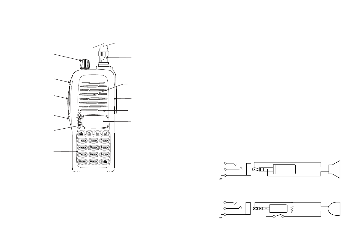
rSQUELCH BUTTON [SQL]
Push and hold to force the squelch open and to adjusts the
squelch level with [Y]/[Z] keys.
tUP/DOWN KEYS [YY]/[ZZ]
A Selects the operating channel or adjusts the squelch level.
B Adjusts the audio level.
• The function Bis available when “dial” is assigned with [VOL] in
INITIAL SET MODE
(p. 51).
yKEY PAD (pgs. 3–6)
Used to enter operating frequency, the DTMF codes, etc.
uANTENNA CONNECTOR
Connects the supplied antenna.
i[SP]/[MIC] JACK
Connect an optional speaker-microphone or headset, if desired.
The internal microphone and speaker will not function when ei-
ther is connected.
DExternal connection
NOTE: When connecting or disconnecting an external speaker-
microphone, first turn the transceiver power OFF.
oFUNCTION DISPLAY (pgs 7, 8)
‘‘Switches, controls, keys and
connectors
qCONTROL DIAL [VOL]
A Adjusts the audio level.
B Selects the operating channel or adjusts the squelch level.
• The function Bis available when “dial” is assigned with [VOL] in
INITIAL SET MODE
(p. 51).
wPOWER SWITCH [POWER]
Push for 1 sec. to turn the power ON and OFF.
ePTT SWITCH [PTT]
Push and hold to transmit; release to receive.
q
w
e
r
t
y
o
u
i
Speaker
Micropho
[SP] jack
SP
SP
GND
[MIC] jack
MIC
MIC
GND
PTT
MIC
5 V
MIC GND
SP (AF OUT)
REMOTE
SP GND
External microphone
(Nominal impedance 2k Ω)
33 kΩ
External speaker
(Nominal impedance 8 Ω)
ø3.5 mm
plug
ø2.5 mm
plug

Access to secondary function
Select the call channel. (p. 19)
Selects a memory mode. (p. 19)
Selects VFO mode, aborts direct frequency input,
or cancels scanning, etc. (pgs. 16, 31)
Input digit “1” during frequency input, memory chan-
nel selection, etc. (pgs. 16, 19)
Input digit “2” during frequency input, memory chan-
nel selection, etc. (pgs. 16, 19)
Input digit “3” during frequency input, memory chan-
nel selection, etc. (pgs. 16, 19)
Input digit “4” during frequency input, memory chan-
nel selection, etc. (pgs. 16, 19)
Input digit “5” during frequency input, memory chan-
nel selection, etc. (pgs. 16, 19)
Input digit “6” during frequency input, memory chan-
nel selection, etc. (pgs. 16, 19)
KEY FUNCTION SECONDARY FUNCTION (After [A•
FUNC
] is pushed)
[name]
[A•
FUNC
]
[B•
CALL
]
[C•
MR
]
[D•
CLR
]
[1•
TONE
]
[2•
P
.
BEEP
]
[3•
T
.
SCAN
]
[4•
DUP
]
[5•
SCAN
]
[6•
SKIP
]
4
1
3
1PANEL DESCRIPTION PANEL DESCRIPTION
DKey pad
No function.
No function.
Entering into memory programming/editing mode. (p. 25)
Programs/transfers VFO/memory or call channel contents into
memory channel/VFO when pushed for 1 sec. (pgs. 25, 26)
No function.
Selects a subaudible tone function. (pgs. 21, 35)
Turn the pocket beep function ON and OFF. (p. 37)
Starts the tone scanning. (pgs. 23, 38)
Selects a duplex function (–duplex, +duplex, simplex). (p. 21)
Starts scanning. (p. 31)
Sets and cancels skip setting for memory skip scan during mem-
ory mode. (p. 32)

Input digit “7” during frequency input, memory chan-
nel selection, etc. (pgs. 16, 19)
Input digit “8” during frequency input, memory chan-
nel selection, etc. (pgs. 16, 19)
Input digit “9” during frequency input, memory chan-
nel selection, etc. (pgs. 16, 19)
Input digit “0” during frequency input, memory chan-
nel selection, etc. (pgs. 16, 19)
No function.
Sets the frequency even full 6-digits of frequency
keys have not been pushed. (p. 16)
6
1
PANEL DESCRIPTION
5
1PANEL DESCRIPTION
Starts the priority watch. (p. 33)
Enters to the
SET MODE
. (p. 46)
Toggles between high and low output power. (p. 18)
Enters to DTMF memory mode. (p. 28)
Selects a optional pager or code squelch operation mode. (p.39)
Switches key pad lock function ON and OFF when pushed for 1
sec.
Lock all keys, except [POWER], [PTT], [SQL], audio level adjust-
ment. (p. 19)
[7•
PRIO
]
[8•
SET
]
[9•
HI
/
LO
]
[0•
DTMF
-
M
]
[✱•
OPTION
]
[#•
ENT
]
KEY FUNCTION SECONDARY FUNCTION (After [A•
FUNC
] is pushed)
[name]
DKey pad (Continued)
8
1
PANEL DESCRIPTIONPANEL DESCRIPTION
1
7
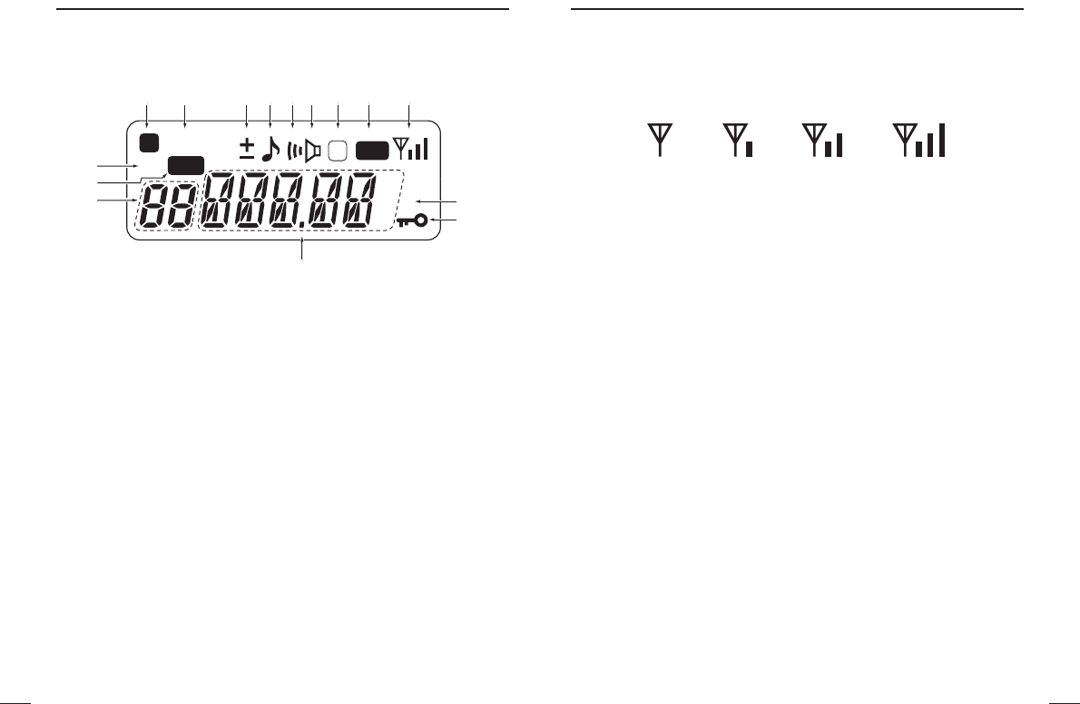
‘‘Function display
qFUNCTION INDICATOR
Appears while the secondary function can be accessed.
wSKIP CHANNEL INDICATOR
Appears when the selected memory channel is set as a “skip”
channel. (p. 32)
eDUPLEX INDICATOR
Either “–” or “+” appears during repeater operation (p. 21).
rTONE ENCODER INDICATOR
Appears when tone encoder is in used. (p. 21)
tPOCKET BEEP INDICATOR
Appears during pocket beep operation (p. 37).
yTONE SQUELCH INDICATOR
Appears when tone squelch is in used. (p. 35)
uDTCS INDICATOR
Appears when DTCS tone is in used. (p. 35)
iTRANSMIT INDICATOR
Appears during transmit. (p. 18)
SKIP
AO
L
MR
F
TX
75
50
25
D
qqqwqeqrqtqyquqiqo
!5
!4
!3
q
!2
!0
!1
oSIGNAL INDICATOR
Appears when the channel is in busy and shows receiving signal
strength as below.
Weak ⇐RX Signal level ⇒Strong
!0 LOW POWER INDICATOR
Appears when low output power is selected. (p. 18)
!1 KEY LOCK INDICATOR (p. 19)
Appears during the key lock function ON.
!2 FREQUENCY READOUT
Shows operating frequency, channel number or channel names,
depending on display mode (p. 20).
!3 MEMORY CHANNEL INDICATOR
Indicates the selected memory channel number or other items
such as the call channel, etc. (pgs. 19, 25)
!4 MEMORY MODE INDICATOR
Appears while in memory mode or channel number indication
mode. (p. 25)
!5 AUTO POWER OFF INDICATOR
Appears while the auto power OFF function is activated. (p. 50)
10
3
BATTERY PACKS
9
2ACCESSORIES
‘‘Accessory attachment
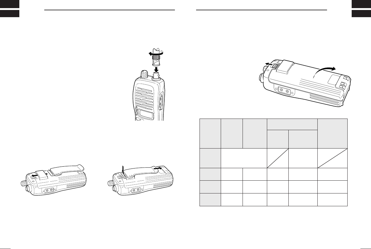
DAntenna
Attach the antenna onto the transceiver as il-
lustrated at right.
Keep the jack cover attached when jacks are
not in use to avoid bad contacts.
DBelt clip
Attach the belt clip to the transceiver as illustrated below.
To attach the belt-clip To release the belt-clip
‘‘Battery pack replacement
Before replacing the battery pack, push [POWER] for 1 sec. to turn
the power OFF.
• Push the battery release
forward, then pull the
battery pack upward
with the transceiver fac-
ing you.
DDBATTERY PACKS
*1Operating periods are calculated under the following conditions;
Tx : Rx : standby =5 : 5 : 90, power save function: auto setting, is activated
*2Operating period depends on the alkaline cells used. (BP-208 only)
yrettaB kcap egatloV yticapaC
doirepgnigrahC gnitarepO *doirep
1
BC-146
ro441-CB 121-CB 49-DAhtiw
BP-208*
2
AArofesacyretta
B)6R( ×enilakla6 A/N
902-PB V2.7srh21srh5.1srh7.5
012-PB V2.7 0561 hAm srh18.5 srh0.2srh11
1100
mAh
222-PB V2.7 006 hAm srh6.5 srh0.1srh4
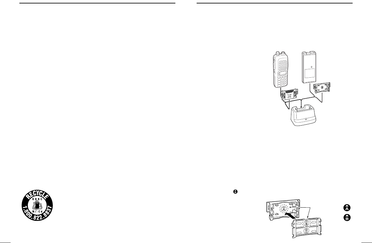
‘‘Battery charging
DRegular charging with the BC-146
The optional BC-146 provides regular charging of optional battery
pack with/without transceiver.
The following is additionally
required:
• An optional AC adaptor.
DAbout AD-99
Attach the spacer (Spacer B/C) to the adaptor (Spacer A) with ori-
entation as illustrated in the diagram below.
• Attach the spacer (Spacer B/C) to the adaptor with the orientation
of the stamp “ ” pointing up.
11
3BATTERY PACKS
12
3
BATTERY PACKS
‘‘Battery caution
• CAUTION! NEVER short the terminals of the battery pack (or
charging terminals of the transceiver). Also, current may flow into
nearby metal objects such as a necklace, so be careful when plac-
ing battery packs (or the transceiver) in handbags, etc.
Simply carrying with or placing near metal objects such as a neck-
lace, etc. causes shorting. This will damage not only the battery
pack, but also the transceiver.
• NEVER incinerate used battery packs. Internal battery gas may
cause an explosion.
• NEVER immerse the battery pack in water. If the battery pack be-
comes wet, be sure to wipe it dry BEFORE attaching it to the
transceiver.
• Clean the battery terminals to avoid rust or miss contact.
• Keep battery contacts clean. It’s a good idea to clean battery ter-
minals once a week.
If your battery pack seems to have no capacity even after being
charged, completely discharge it by leaving the power ON
overnight. Then, fully charge the battery pack again. If the battery
pack still does not retain a charge (or only very little charge), a new
battery pack must be purchased (p. 59).
DDRecycling information (U.S.A. only)
The product that you have purchased contains a
rechargeable battery. The battery is recyclable. At
the end of its life, under various state and local
laws, it may be illegal to dispose of this battery into
the municipal waste stream. Call 1-800-822-8837
for battery recycling options in your area or contact your dealer.
BC-146 + AD-99
Check orientation
for correct charging.
(Insert together with
AD-99.)
Turn power OFF.
Check orientation
and
Spacer A
Spacer B/C
14
3
BATTERY PACKS
13
3BATTERY PACKS
‘‘Charging NOTE
Prior to using the transceiver for the first time, the battery pack must
be fully charged for optimum life and operation.
• Recommended temperature range for charging:
+10°C to +40°C (50°F to 140°F).
• Use the supplied charger or optional charger (BC-144/BC-121 for
rapid charging, BC-146 for regular charging) only. NEVER use
other manufacturers’ chargers.
The optional BP-222, BP-209 or BP-210 battery packs include
rechargeable Ni-Cd (Ni-MH: BP-210) batteries and can be charged
approx. 300 times. Charge the battery pack before first operating
the transceiver or when the battery pack becomes exhausted.
If you want to charge the battery pack more than 300 times, the fol-
lowing points should be observed:
• Avoid over charging. The charging period should be less than
24 hours.
• Use the battery until it becomes almost completely exhausted
under normal conditions. We recommend battery charging after
transmitting becomes impossible.
DDBattery pack life
When the operating period becomes extremely short even after
charging the battery pack fully, a new battery pack is needed.
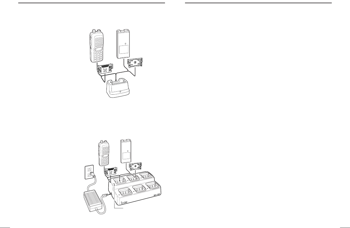
DRapid charging with the BC-144 (#11)
The optional BC-144 (#11)
provides rapid charging of op-
tional battery packs.
The following are additionally
required:
• An AC adaptor (may be sup-
plied with the BC-144 de-
pending on version).
DRapid charging with the BC-121+AD-94 (#11)
The optional BC-121 allows up to 6 battery packs to be charged si-
multaneously. The following
are additionally required.
• Six AD-94 (#11).
• An AC adaptor (may be
supplied with the BC-121
depending on version).
MULTI-CHARGER
AC adapter
(purchased separately)
Charge indicator
(each indicator functions
independently)
Turn power OFF.
Check orientation
for correct charging.
(Insert together with
AD-99.)
BC-144 + AD-99
Check orientation
for correct charg-
ing. (Insert togeth-
er with AD-99.)
Turn power OFF.
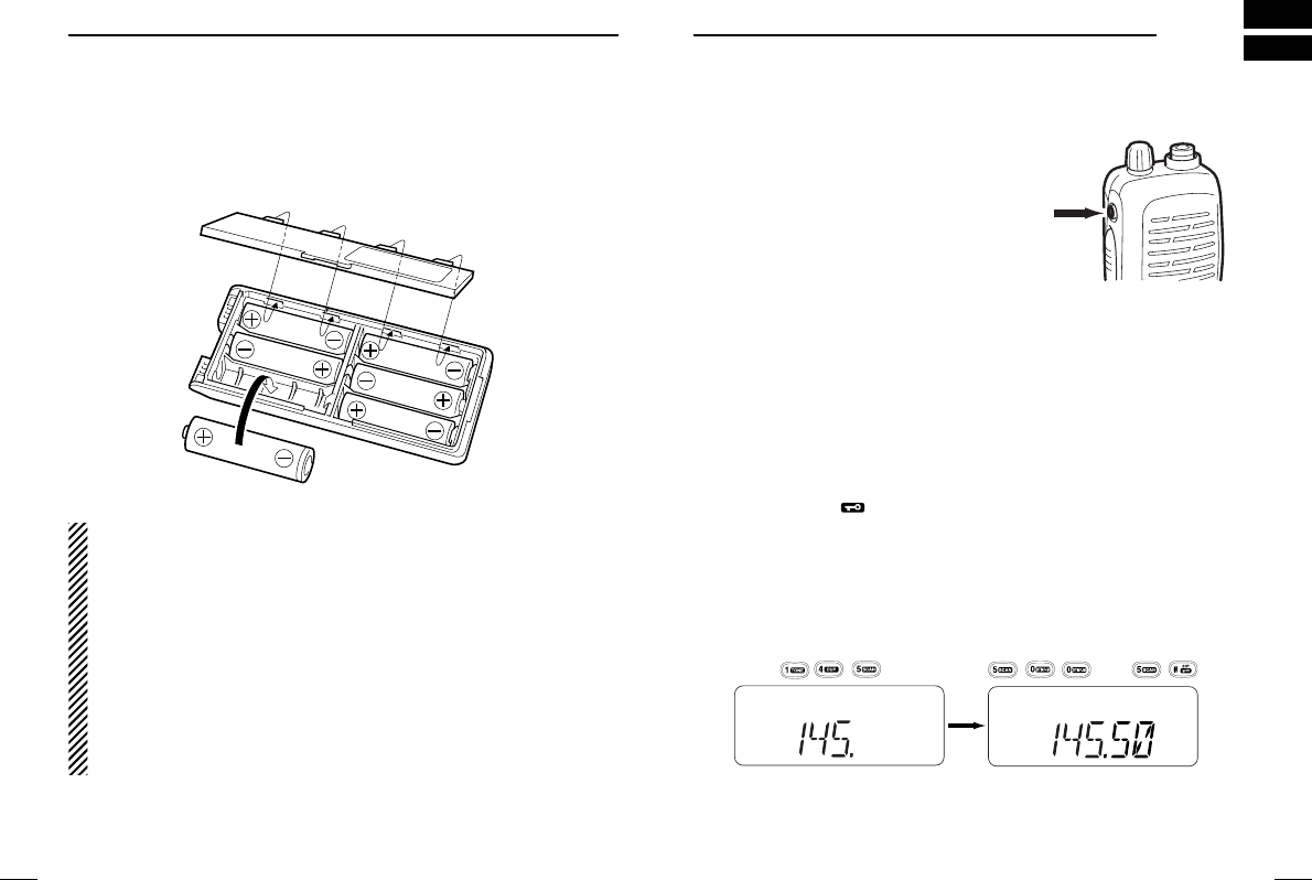
■Power ON
Push [POWER] for 1sec. to turn
power ON.
■Setting a frequency
DVia the keypad
qPush [D.
CLR
] to select VFO mode, if necessary.
wPush 6 digit keys, starting from the 100 MHz digit, to enter
the desired frequency.
• When [#•
ENT
]is pushed after three or more digits are entered,
also the frequency is set.
• When a digit is mistakenly input, push [D.
CLR
]to abort imputing.
• “2” and “7” are acceptable for the 1 kHz digit (depending on the 10
kHz digit).
16
4
BASIC OPERATION
15
3BATTERY PACKS
‘‘Battery case (optional for some versions)
When using a BP-208 BATTERY CASE attached to the transceiver,
install 6 AA (R6) size alkaline batteries as illustrated below.
DDCAUTIONS
• Use ALKALINE batteries only.
• Make sure all battery cells are the same brand, type and ca-
pacity.
• Never mix old and new batteries.
Either of the above may cause a fire hazard or damage the
transceiver. If ignored.
• Never incinerate used battery cells since internal battery gas
may cause them to rupture.
• Never expose a detached battery case to water.
If the battery case gets wet, be sure to wipe it dry before using.
MR
or
MR
Push
Push for 1 sec.

17
4BASIC OPERATION
18
4
BASIC OPERATION
■Receive and transmit
qPush [POWER] for 1sec. to turn the power ON.
wAdjust volume to the desired level.
eSet a frequency.
When a signal is received:
• Squelch opens and audio is emitted from the speaker.
• Signal indicator shows the relative signal strength level.
rPush [9•
H
/
L
] after pushing [A•
FUNC
] to toggle output power be-
tween high and low.
• “L” appears when low output power is selected.
tPush and hold [PTT] to transmit, then speak into the micro-
phone.
• “TX” appears.
•Do not hold the microphone too close to your mouth or speak too
loudly. This may distort the signal.
yRelease [PTT] to receive
✔For your information
Monitor function:
Push and hold [SQL] to listen to weak signals that do not open the
squelch.
DUsing other ways
Via the [YY]/[ZZ] keys
Each push increments/decrements the frequency with the selected
tuning step.
Using the [VOL]
Rotate the [VOL] to increment/decrement the frequency with the se-
lected tuning step.
• This function is available when “dial” is assigned with [VOL] in
INITIAL
SET MODE
(p. 51).
✔For your information
Tuning steps:
The transceiver has 8 tuning steps as follows:
5 kHz 10 kHz 12.5 kHz 15 kHz
20 kHz 25 kHz 30 kHz 50 kHz
• A tuning step is selected in
SET MODE
. (p. 47)
■Setting audio/squelch level
DTo set the audio level
Rotate the [VOL] to set desired audio level while receiveing the
signal.
• When no signal is received, push and hold [SQL] while setting
audio level
• When “dial” is assigned [VOL], push [Y]/[Z] to adjust audio output
level. (p. 51)
DTo set the squelch level
While pushing [SQL], push [Y]/[Z] to set the squelch level.
• The squelch level “1” is loose squelch,“10’ is tight squelch.
• When “dial” is assigned [VOL], rotate [VOL] while [SQL] is pushed.
(p. 51)
20
4
BASIC OPERATION
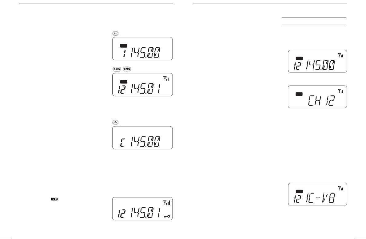
■Selecting a memory channel
qPush [C•
MR
] to select memory mode.
•“
X” appears.
wPush 2 digit keys to select the de-
sired memory channel (or push the
[Y]/[Z] keys).
• When “dial” is assigned [VOL], rotate
[VOL] to select the memory channel.
(p. 51)
• The memory channels 0–9 are pro-
ceeded by a “0.”
■Selecting call channel
Push [B•
CALL
] to select the call chan-
nel.
• “C” displayed instead of memory
channel number.
• Push [D•
CLR
] or [C•
MR
] to return to
previous indication.
■Key lock function
The key lock function prevents accidental frequency changes and
function activation.
Push [#•
ENT
] for 1 sec. after push-
ing [A•
FUNC
] to toggle the function ON
and OFF.
•“é” appears while the lock func-
tion is activated.
• [POWER], [PTT], [VOL] and [SQL] can be operated regardless of
this setting.
MR
MR
SKIP
AO
L
MR
F
TX
75
50
25
D
19
4BASIC OPERATION
MR
■Display type
The transceiver has 3 display types to match your operating style.
The display type is selected in the
INITIAL SET MODE
(p. 51).
Frequency indication type is used basic
amateur radio operation.
Channel indication type is used to sim-
plify operation. In this mode only pre-
programmed memory channel numbers
are displayed only.
VFO mode cannot be selected.
• When the channel indication type is selected, the following functions
can only be performed.
- Scan function (p. 30)
- Output power setting (p. 18)
- DTMF memory function (p. 28)
- Key lock function (p. 19)
- Scan pause timer setting, function key timer setting and LCD
backlight setting in
SET MODE
(p. 47)
Channel name indication type is used to
simplify operation same as above. In
this mode pre-programmed memory
channel names are displayed.
VFO mode selectable.
• Programmed frequency is indicated when the channel name is not
pre-programmed in the selected memory channel.
• Push and hold [SQL] to displayed operating frequency.
MR
MR
USING
INITIAL SET MODE
MR
21
5REPEATER OPERATION
22
5
REPEATER OPERATION
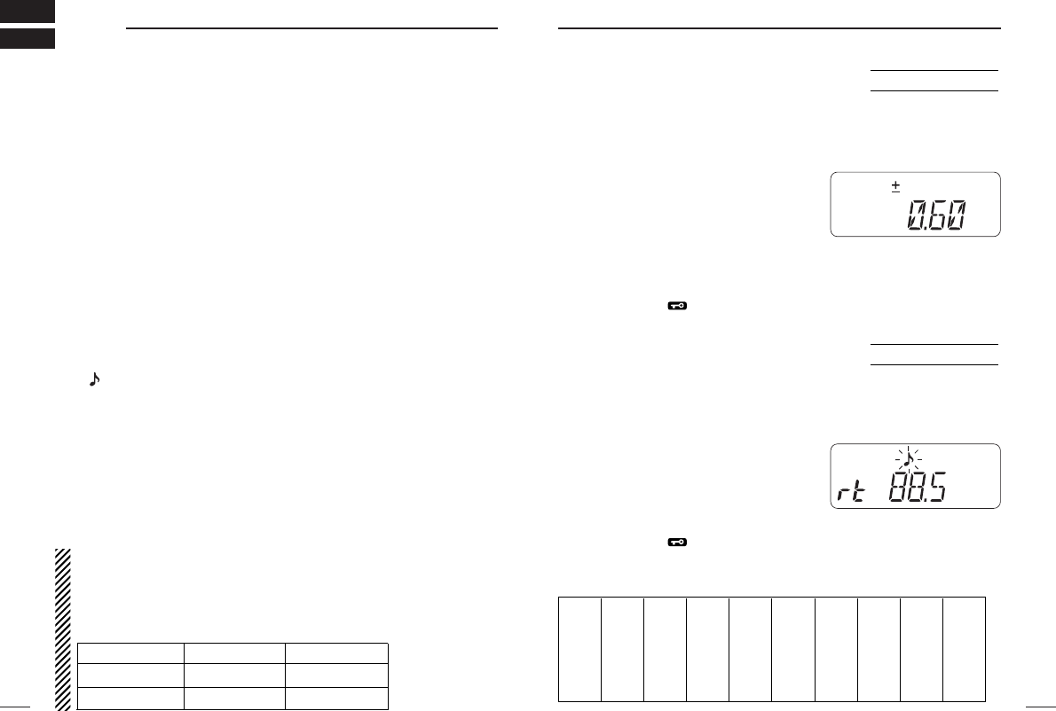
■Offset frequency
When communicating through a repeater, the transmit frequency is
shifted from the receive frequency by an amount determined by the
offset frequency.
qPush [8•
SET
] after pushing [A•
FUNC
]
to enter
SET MODE
.
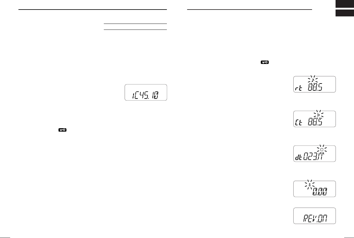
wPush [Y]/[Z] several times until “±”
and offset frequency appear.
eRotate [VOL] to select the desired offset frequency.
• Selectable steps are the same as the pre-set tuning steps.
• The unit of displayed offset frequency is “MHz.”
rPush [#•
ENT
] to fix the offset frequency and exit
SET MODE
.
■Subaudible tones
Some repeaters require subaudible tones to be accessed. Sub-
audible tones are superimposed over your normal signal and must
be set in advance.
qPush [8•
SET
] after pushing [A•
FUNC
]
to enter
SET MODE
.
wPush [Y]/[Z] one or more times until
“rt” appears.
eRotate [VOL] to select the desired subaudible tone.
rPush [#•
ENT
] to enter the selected tone and exit set mode.
USING
SET MODE
SKIP
AO
LM
MR
F
TX
75
50
25
Available subaudible tone frequencies (unit: Hz)
67.0 79.7 94.8 110.9 131.8 156.7 171.3 186.2 203.5 229.1
69.3 82.5 97.4 114.8 136.5 159.8 173.8 189.9 206.5 233.6
71.9 85.4 100.0 118.8 141.3 162.2 177.3 192.8 210.7 241.8
74.4 88.5 103.5 123.0 146.2 165.5 179.9 196.6 218.1 250.3
77.0 91.5 107.2 127.3 151.4 167.9 183.5 199.5 225.7 254.1
USING
SET MODE
SKIP
AO
LM
MR
F
TX
75
50
25
D
■General
When using a repeater, the transmit frequency is shifted from the
receive frequency by the offset frequency. It is convenient to pro-
gram repeater information into memory channels.
qSet the receive frequency (repeater output frequency).
wPush [4•
DUP
] after pushing [A•
FUNC
] several times to select “–” or
“+.”
• “–” indicates the transmit frequency is shifted down; “+” indicates
the transmit frequency is shifted up.
• Flashing “–” or “+” indicates the reversed duplex mode is selected
in
SET MODE
(p. 46).
• When the auto repeater function is in used (USA version only) this
selection and step eare not necessary. (p. 24)
ePush [1•
TONE
] after pushing [A•
FUNC
] to activate the subaudible
tone encoder, according to repeater requirements.
• “ ” appears.
• Select the desired sub audible tone frequency, if necessary. (p. 22)
rPush and hold [PTT] to transmit.
• The displayed frequency automatically changes to the transmit fre-
quency (repeater input frequency).
• If “OFF” appears, check the offset frequency and direction.
tRelease [PTT] to receive.
yPush and hold [SQL] to check whether the other station’s trans-
mit signal can be directly received or not.
About reversed duplex mode
When the reversed duplex mode is selected, the receive fre-
quencies shifts. Each receive and transmit frequency are shown
in the table below with the follow conditions; entered freq. : 145.00
MHz, duplex direction : – (negative), frequency offset : 0.6 MHz
Reversed OFF ON
Rx frequency 145.30 MHz 144.70 MHz
Tx frequency 144.70 MHz 145.30 MHz

24
5
REPEATER OPERATION
23
5REPEATER OPERATION
■Auto repeater
function (USA version only)
The USA version automatically activates the repeater settings (du-
plex, ON/OFF, duplex direction, tone encoder ON/OFF) when the
operating frequency falls within or outside of the general repeater
output frequency range. The offset and repeater tone frequencies
are not changed by the auto repeater function, reset these fre-
quencies, if necessary.
qWhile pushing [Y]+[Z], turn the power ON to enter
INITIAL SET
MODE
.
wPush [Y]/[Z] several times until
“RPt.” appears.
eRotate [VOL] to select the desired
condition.
• “OF”—the auto repeater function is
turned OFF;
“R1”—the auto repeater function acti-
vates for duplex only;
“R2”—the auto repeater function acti-
vates for duplex and tone.
rPush [#•
ENT
] to exit
INITIAL SET
MODE
.
USING
INITIAL SET MODE
Frequency range and offset direction
FREQUENCY RANGE DUPLEX DIRECTION
145.200–145.495 MHz “–” appears
146.610–146.995 MHz
147.000–147.395 MHz “+” appears
SKIP
AO
LM
MR
F
TX
75
50
25
D
SKIP
AO
LM
MR
F
TX
75
50
25
D
SKIP
AO
LM
MR
F
TX
75
50
25
D
✔Convenient
Tone scan function: When you don’t know the subaudible tone
used for a repeater, the tone scan is convenient for detecting the
tone frequency.
Push [3•
T
.
SCAN
] after pushing [A•
FUNC
] to start the tone scan.
• Push [D•
CLR
] to cancel the scan.
• When the wanted tone frequency is detected, the scan pauses.
DDTone information
Some repeaters require a tone to be accessed.
DTMF TONES
While pushing [PTT], push the desired DTMF keys (0–9, A–F) to
transmit DTMF tones.
• The transceiver has 5 DTMF memory channels (p. 28).
1750 Hz TONE
While pushing [PTT], push [Y] or [Z] for 1 to 2 sec. to transmits
1750 Hz tone signal.

25
6MEMORY PROGRAMMING
26
6
MEMORY PROGRAMMING
■Channel name programming
qSelect a channel name indication type in
INITIAL SET MODE
(pgs. 20, 51).
wPush [C•
MR
] to select memory mode, if necessary.
ePush [8•
SET
] after pushing [A•
FUNC
] to enter to channel name
programming mode.
• A currently editing character is flashed.
tRotate [VOL] to select a character.
yPush [Y] to move to the right, [Z] to move to the left.
• Up to 5-digit channel names can be programmed.
• Usable character are; A–Z, 0–9, ”space“, +, –, =, ✱, /, [, and ].
uPush [#•
ENT
] to fix and exit channel name programming
mode.
■Memory transferring
Memory (call) channel contents can be transfer to VFO or to an-
other memory channel.
DMemory/call ➾VFO
qSelect the memory (call) channel to be transferred:
Push [C•
MR
] ([B•
CALL
]) to select memory (call) mode.
Push [Y]/[Z] to select the memory channel.
• When “dial” is assigned [VOL], rotate [VOL] to select the memory
channel. (p. 51)
wPush [C•
MR
] for 1 sec. after pushing [A•
FUNC
] to transfer the se-
lected memory contents to the VFO.
• VFO mode is selected automatically.
■General
The transceiver has 100 memory channels (plus 3 pairs of scan
edges and 1 call channels) for storage of often-used frequencies.
DMemory channel contents
The following information can be programmed into memory:
• Operating frequency
• Duplex direction (+ or –) with an offset frequency (pgs. 21, 22)
• Subaudible tone encoder or tone squelch ON/OFF (pgs. 21, 35)
• Subaudible tone and tone squelch frequencies (pgs. 22, 36)
• Skip information* (p. 32)
*Except for scan edge channels.
■Programming the memory/call
channels
qPush [D•
CLR
] to select VFO mode, if necessary.
wSet the desired frequency.
eSet other informations such as tone, duplex, etc. as desired.
rPush [C•
MR
] for 1 sec. (until emits 3 beeps) after pushing
[A•
FUNC
] to program the information into the displayed memory
channel and return to VFO
• Continue to hold [C•
MR
] down for 1
sec. after 3 beeps emission, to incre-
ment displayed memory channel
number.
MR

27
6MEMORY PROGRAMMING
28
7
DTMF MEMORY
■Programming a DTMF code
The transceiver has 5 DTMF memory channels (d0 to d4) for
storage of often-used DTMF codes of up to 24 digits.
qPush [0•
DTMF
-
M
] after pushing
[A•
FUNC
] to enter DTMF memory.
• One of “d0” to “d4” appears.
wRotate [VOL] to select the desired
channel.
ePush [0•
DTMF
-
M
] for 1 sec. after
pushing [A•
FUNC
] to enter DTMF
programming mode.
• “_ _ _ _ _” appears.
• Programmed memories can be cleared in this way.
rPush the digit keys, [A•
FUNC
], [B•
CALL
], [C•
MR
], [D•
CLR
], [✱•
OP
-
TION
] and [#•
ENT
] to enter the desired DTMF code.
• A maximum of 24 digits can be input.
•[✱•
OPTION
] enters as “E”, [#•
ENT
] enters as “F.”
• If a digit is mistakenly input, push [SQL] or [PTT] momentarily
then repeat from step q.
tPush [SQL] or [PTT] to input the digits and exit DTMF pro-
gramming mode.
• Programmed DTMF codes sound when [SQL] is pushed to exit.
MR
MR
DMemory/call ➾call/memory
qSelect the memory (call) channel to be transferred:
Push [C•
MR
] ([B•
CALL
]) to select memory (call) mode.
Push [Y]/[Z] to select the memory channel.
• When “dial” is assigned [VOL], rotate [VOL] to select the memory
channel. (p. 51)
wPush [C•
MR
] momentarily after pushing [A•
FUNC
].
• “--” and “X” flashes.
ePush [Y]/[Z] to select the target memory.
• When “dial” is assigned [VOL], rotate [VOL] to select the memory
channel. (p. 51)
rPush [C•
MR
] for 1 sec after pushing [A•
FUNC
].
• Memory mode is selected and the contents are transferred to
the target memory.
DClearing a memory
qPush [C•
MR
] after pushing [A•
FUNC
] to enter memory transfer
mode.
•“
X” and a memory channel number flash.
wPush [Y]/[Z] to select the memory channel to be cleared.
• When “dial” is assigned [VOL], rotate [VOL] to select the memory
channel. (p. 51)
• The call channel cannot be cleared.
ePush [C•
MR
] after pushing [A•
FUNC
] momentarily, then push
[C•
MR
] for 1 sec after pushing [A•
FUNC
] again.
• Perform this operation within 1.5 sec.
• The contents of the selected memory are cleared.
rPush [D•
CLR
] to return to regular operation.
29
7DTMF MEMORY
30
8
SCAN OPERATION
PROGRAMMED SCAN
MEMORY (SKIP) SCAN
Mch 0 Mch 6
Mch 1 Mch 3
Mch 2 Mch 4 Mch 5
Mch 7
Mch 99 Mch 10 Mch 9 Mch 8
Scan
Scan edges
PRIORITY WATCH
Mch 3
Priority memory channel scan
Priority channel
50 msec.
VFO frequency
145.20 MHz
5 sec.
Mch 3
Mch 5Mch 1
Mch 2 Mch 4
Mch 6
SKIP
Mch 99
50 msec.
Memory
scan
Priority channel
Priority memory channel watch
VFO frequency
145.20 MHz
5 sec.
SKIP
SKIP
Band edge Band edge
Jump
1A
2A
3A
1b
2b
3b
■Scan types■Transmitting a DTMF code
DUsing a DTMF memory channel
qPush [0•
DTMF
-
M
] after pushing [A•
FUNC
] to enter DTMF memory.
wRotate [VOL] to select the desired channel.
rPush [SQL] or [PTT] to exit DTMF memory mode.
tWhile pushing [PTT], push [SQL] to transmit the selected DTMF
memory.
• After the DTMF code is transmitted, returns to receive automati-
cally.
DManual DTMF code transmission
qWhile pushing [PTT], push digit keys, A–F to transmit a
DTMF code manually.
• Once DTMF code key is pushed, the transmission is kept for 1 sec.
after release the key even [PTT] is released.
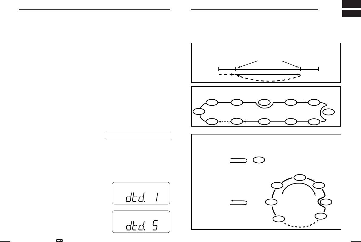
■DTMF
transmission speed
When slow DTMF transmission speeds are required with DTMF
memory transmission (as for some repeaters), the transceiver’s rate
of DTMF transmission can be adjusted.
qWhile pushing [Y] and [Z], turn the
power on to enter
INITIAL SET MODE
.
wPush [Y]/[Z] several times until “dtd”
appears.
eRotate [VOL] to select the desired
DTMF transmission speed.
• Four speeds are available: “1” (100
msec. intervals) is the fastest; “5” (500
msec. intervals) is the slowest.
rPush [#•
ENT
] to exit
INITIAL SET MODE
.
USING
INITIAL SET MODE
MR
MR

32
8
SCAN OPERATION
31
8SCAN OPERATION
■Programmed scan
Programmed scan repeatedly scans between two user-pro-
grammed frequencies (memory channels “1A–3A” and “1b–3b”) or
scans between upper and lower band edges. This scan is useful
for checking for signals within a specific frequency range such as
repeater output frequencies, etc.
qPush [D•
CLR
] to select VFO mode, if necessary.
wPush [5•
SCAN
] after pushing [A•
FUNC
] to start the scan, then a
selected scan edge appears as “P1”, “P2”, “P3” or “AL.”
• To change scan edge, push [8•
SET
] after pushing [A•
FUNC
] several
times until desired scan edge is appeared.
• “AL” for full scan, “P1”, “P2” and “P3” for programmed scan be-
tween the programmed scan edge channels as “1A”–“1b”,
“2A”–“2b” and “3A”–“3b”.
• To change the scan direction, push [Y] or [Z].
• When “dial” is assigned [VOL], rotate [VOL] to change the scan di-
rection. (p. 51)
ePush [D•
CLR
] to stop the scan.
NOTE: Scan edges, 1A–3A/1b–3b, must be programmed in ad-
vance. (Program them in the same manner as regular memory
channels. (p. 25))
If the same frequencies are programmed into the scan edges,
programmed scan will not proceed.
■Memory (skip) scan
Memory scan repeatedly scans all programmed memory chan-
nels, except those set as skip channels.
qPush [C•
MR
] to select memory mode, if necessary.
•“
X” appears.
wPush [5•
SCAN
] after pushing [A•
FUNC
] to start the scan.
• To change the scan direction, push [Y] or [Z].
• When “dial” is assigned [VOL], rotate [VOL] to change the scan di-
rection. (p. 51)
ePush [D•
CLR
] to stop the scan.
DSetting skip channels
In order to speed up the scan interval, you can set memory
channels you don’t wish to scan as skip channels.
qPush [C•
MR
] to select memory mode, if necessary.
•“
X” appears.
wSelect a memory channel to set as a skip channel.
ePush [6•
SKIP
] after pushing [A•
FUNC
] to toggle the skip setting
ON and OFF.
• “SKIP” appears when the channels is set as a skip channel.

34
8
SCAN OPERATION
33
8SCAN OPERATION
■Priority watch
Priority watch checks for signals on “priority channels” while oper-
ating on a VFO frequency.
DMemory or call channel watch
While operating on a VFO frequency, memory or call channel watch
monitors for signals in the selected memory or call channel every
5 sec.
qSelect the desired memory channel or the call channel.
wPush [D•
CLR
] to select VFO mode.
ePush [7•
PRIO
] after pushing [A•
FUNC
] to start watching.
• VFO is displayed, then the decimal point “.”, on the frequency read-
out flashes.
• The priority channel is monitored every 5 sec.
• When the signal is detected on the priority channel, the watching
is paused according to setting of scan resume condition.
rPush [D•
CLR
] to stop watching.
DMemory scan watch
While operating on a VFO frequency or the call channel, memory
scan watch monitors for signals in each memory channels in se-
quence every 5 sec.
q Push [C•
MR
] to select memory mode, if necessary.
•“X” appears.
wPush [5•
SCAN
] after pushing [A•
FUNC
] to start the memory scan.
ePush [7•
PRIO
] after pushing [A•
FUNC
] to start the watching.
• VFO is displayed, then the decimal point “.”, on the frequency read-
out is flashed.
• When the signal is detected on priority channel, the watching is
paused according to setting of scan resume condition.
rPush [D•
CLR
] to stop the watching.
■Scan resume
condition
When a signal is received during
scanning, the scan resume condi-
tion determines what action the
transceiver takes. The transceiver
has 2 scan resume conditions avail-
able as illustrated at right. Use
SET
MODE
to select the one which best
suits your needs.
qPush [8•
SET
] after pushing [A•
FUNC
] to enter
SET MODE
.
wPush [Y]/[Z] several times until “SCP” or “SCt” appears.
eRotate [VOL] to select the desired scan resume condition.
•Pause scan: when receiving a signal,
scan pauses on the signal until it ap-
pears. Resumes after 2 sec. from the
signal disappears.
Timer scan: when receiving a signal,
scan pauses on the signal for 5 sec., 10
sec. or 15 sec. then resumes.
rPush [#•
ENT
] to set and exit
SET MODE
.
Pause
scan
Receiving
a signal
Timer
scan
5, 10 or 15 sec.
2 sec.
Pause scan
Timer scan
SKIP
AO
LM
MR
F
TX
75
50
25
DD
SKIP
AO
LM
MR
F
TX
75
50
25
D
USING
SET MODE
36
9
SUBAUDIBLE TONES
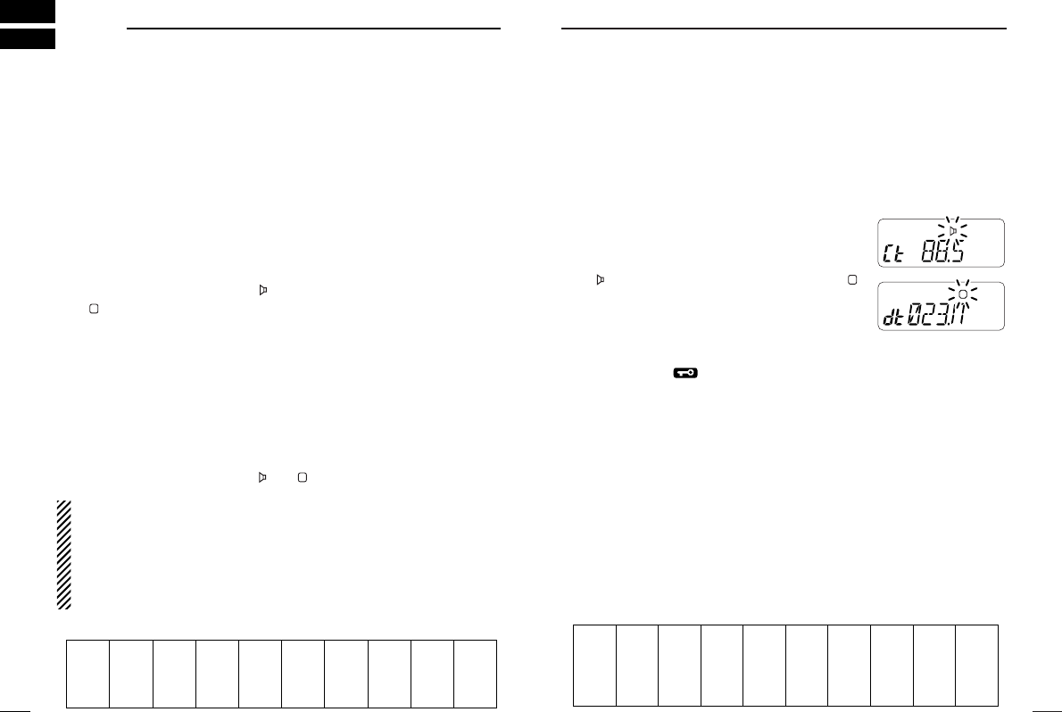
DSetting subaudible tones for tone squelch
operation
Separate tone frequencies can be set for tone squelch operation
than repeater operation (the same range of tones is available— see
below). As the repeater tones, these are set in set mode.
qSelect VFO or memory channel.
wPush [A•
FUNC
] + [8•
SET
] to enter set mode.
ePush [∫] or [√] several times until “Ct” ap-
pears when selecting CTCSS, or “dt” ap-
pears when selecting DTCS.
• “ ” flashes when selecting CTCSS, or “ ”
flashes when selecting DTCS.
rRotate [VOL] to select the desired subaudible tone.
tPush [#•
ENT
] to program the selected tone and exit set
mode.
When set mode is selected from memory mode.
yPush [C•
MR
] for 1 sec. after [A•
FUNC
] is pushed.
• Emits 3 beeps.
• VFO mode is selected automatically.
uPush [C•
MR
] for 1 sec. after [A•
FUNC
] is pushed.
• Emits 3 beeps.
The step yand uare necessary when overwriting the memory
contents for permanently. Therefore, the set tone frequency is used
for temporarily operation only, these steps are not necessary.
•Subaudible CTCSS tone frequency list
D
67.0
69.3
71.9
74.4
77.0
79.7
82.5
85.4
88.5
91.5
94.8
97.4
100.0
103.5
107.2
110.9
114.8
118.8
123.0
127.3
131.8
136.5
141.3
146.2
151.4
156.7
159.8
162.2
165.5
167.9
171.3
173.8
177.3
179.9
183.5
186.2
189.9
192.8
196.6
199.5
203.5
206.5
210.7
218.1
225.7
229.1
233.6
241.8
250.3
254.1
MR
F
TX
MR
F
D
TX
35
SUBAUDIBLE TONES
9
‘‘Tone squelch
DOperation
The tone squelch opens only when receiving a signal containing a
matching subaudible tone. You can silently wait for calls from group
members using the same tone.
qSet the operating frequency.
•
Set the AF and squelch to the desired level as the normal operation.
wSet the desired subaudible tone in the set mode.
• See right for programming.
ePush [1•
TONE
] after [A•
FUNC
] is pushed.
• Repeat several times until “ ” appears when selecting CTCSS, or
“ ” appears when selecting DTCS.
rWhen the received signal includes a matching tone, squelch
opens and the signal can be heard.
• When the received signal’s tone does not match, tone squelch
does not open, however, the S-indicator shows signal strength.
• To open the squelch manually, push and hold [SQL].
tOperate the transceiver in the normal way.
yTo cancel the tone squelch, push [1•
TONE
] after [A•
FUNC
] is
pushed.
• Repeat several times until “ ” or “ ” disappear.
NOTE: The transceiver has 50 tone frequencies and conse-
quently their spacing is narrow compared to units having 38
tones. Therefore, some tone frequencies may receive interfer-
ence from adjacent tone frequencies.
To prevent interference from adjacent tone frequencies, use the
frequencies as following table is recommended.
D
D
67.0
69.3
71.9
74.4
88.5
91.5
94.8
97.4
114.8
118.8
123.0
127.3
151.4
156.7
162.2
167.9
203.5
210.7
218.1
225.7
77.0
79.7
82.5
85.4
100.0
103.5
107.2
110.9
131.8
136.5
141.3
146.2
173.8
179.9
186.2
192.8
233.6
241.8
250.3
• Recommended tone frequencies
38
9
SUBAUDIBLE TONES
‘‘Tone scan
By monitoring a signal that is being operated with repeater, pocket
beep or tone squelch function, you can determine the tone fre-
quency necessary to access a repeater or open a squelch.
qSet the frequency to be checked for a tone frequency or code.
wPush [1•
TONE
] after [A•
FUNC
] is pushed.
• Repeat several times to select the tone condition or type to be
scanned. (One of “ ”, “ ” or “ ” appears)
• The tone scan can be operated even the tone condition or type is
selected.
ePush [3•
T
.
SCAN
] after [A•
FUNC
] is pushed to starts the tone scan.
• To change the scanning direction, push [∫] or [√].
rWhen the CTCSS tone frequency or DTCS code is matched, the
squelch opens and the tone frequency or code is temporarily
programmed into the selected mode such as memory or call
channel.
• The tone scan pauses when a CTCSS tone frequency or 3-digit
DTCS code is detected.
• The decoded CTCSS tone frequency or 3-digit DTCS code is used
for the tone encoder or tone encoder/decoder depending on the
selected tone condition or type in step w.
- No indication : Cannot be used for operation.
- “ ” : CTCSS tone encoder
- “ ” : CTCSS tone encoder/decoder
- “ ” : DTCS tone encoder/decoder
tPush [D•
CLR
] to stop the scan.
D
D
MR
F
TX
MR
F
D
TX
SUBAUDIBLE TONES
9
37
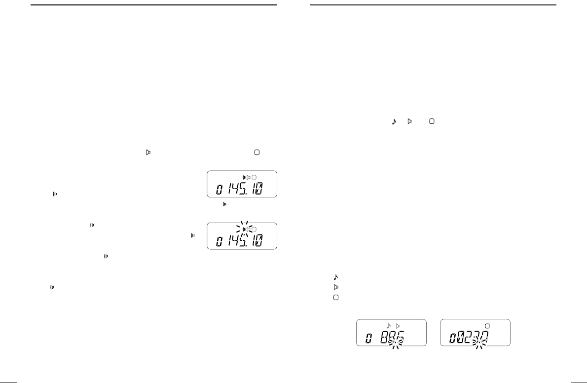
‘‘Pocket beep operation
This function uses subaudible tones for calling and can be used as
a “common pager” to inform you that someone has called when you
were away from the transceiver.
DWaiting for a call from a specific station
qSet the operating frequency.
wSet the desired CTCSS tone frequency or DTCS code in the set
mode.
• See p. 36 for programming details.
ePush [1•
TONE
] after [A•
FUNC
] is pushed.
• Repeat several times until “ ” appears when CTCSS, or “ ” ap-
pears when DTCS is selected.
rPush [2•
P
.
BEEP
] after [A•
FUNC
] is pushed to
activates the pocket beep function.
• “ ” appears.
tWhen a signal with the matched tone is re-
ceived, the transceiver emits beep tones
and flashes “ .”
• Beep tones sound for 30 sec. and “”
flashes. To stop the beeps manually,
push any key. “ ” continues blinking until
step yis operated.
yPush [PTT] to answer.
• “” disappears and cancels the pocket beep function automatically.
D
MR
F
D
TX
“ ” appears
MR
F
D
TX
40
10
PAGER/CODE SQUELCH
‘‘
Code programming
DDBefore programming
The pager and code squelch functions require ID codes and a
group code. These codes are 3-digit DTMF codes and must written
into the code channels before operation.
qDecide the ID code of each transceiver and a group code for
your group.
wDecide whether you want to return to normal operation or code
squelch operation after a connection is made.
eProgram the ID code, group code and transmit codes (other sta-
tion’s codes) as below.
DDCode channel assignment
*
Channel CP automatically memorized an ID code when receiving a
pager call. The contents in channel CP cannot be changed manually.
Optional UT-108 required
ID OR CODE CHANNEL “RECEIVE ACCEPT” OR
GROUP CODE NUMBER “RECEIVE INHIBIT”
Your ID code 0 “Receive accept” only
Other parties’ 1–6 “Receive inhibit” should be
ID code
programmed in each channel.
Group code One of 1–6 “Receive accept” must be
programmed.
Memory space* P “Receive inhibit” only.
39
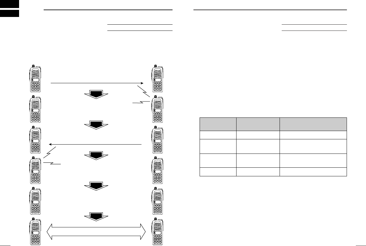
10 PAGER/CODE SQUELCH
‘‘Pager function
This function uses DTMF codes for paging and can be used as a
“message pager” to confirm you of a caller’s identification even
when you leave the transceiver temporarily unattended.
Optional UT-108 required
Pager selective code (push [PTT])
Beep Beep
Beep
Answer back (manual)
Beep Beep
Beep
Set both transceivers to either
code squelch or non-coded operation
Communication
42
10
PAGER/CODE SQUELCH
•Receive accept/receive inhibit
➥“Receive accept” (“SKIP” indicator does not appear) accepts
pager calls when the transceiver receives a signal with a code
the same as that in the code channel.
➥“Receive inhibit” (“SKIP” indicator appears) rejects calls even
when the transceiver receives a code the same as that in the
code channel. Transmit codes should therefore be programmed
for “receive inhibit,” otherwise the transceiver will not reject un-
necessary calls.
•Pager/code squelch operation during channel indication
To use these functions in channel indication, the pager/code
squelch setting must be programmed with other memory contents
before selecting channel number indication.
41
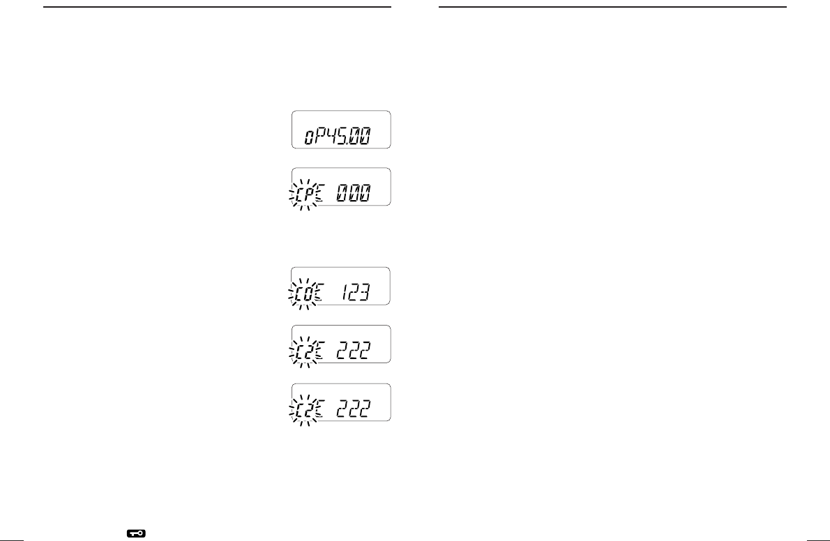
10PAGER/CODE SQUELCH
DDCode programming
An ID code MUST be programmed into code channel C0. Up to 6
transmit codes are programmable into code channels, C1 to C6, if
required.
qPush [✱•
OPTION
] after [A•
FUNC
] is pushed.
• Pager mode is selected.
• 100 MHz digit shows “P.”
wPush [8•
SET
] after [A•
FUNC
] is pushed.
• One of “CP” or “C0” to “C6” flashes.
• “C0” is the ID code and “C1” to “C6” are
transmit code.
eRotate [VOL] to select code channel C0.
• A different ID code must be programmed into each transceiver.
rEnter the desired 3-digit ID code via the
keypad.
tRotate [VOL] to select a transmit code
channel from C1 to C6.
yEnter the desired 3-digit transmit code via
the keypad.
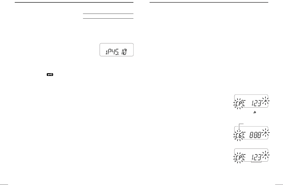
uPush [6•
SKIP
] after [A•
FUNC
] is pushed to
set the channel for “receive inhibit” or “re-
ceive accept.”
• When “receive inhibit” is set, “SKIP” ap-
pears as at right.
• Code channel C0 cannot be set as “receive inhibit.”
• See the following table for “receive accept” and “receive inhibit” de-
tails.
iRepeat steps tand yto set additional transmit code channels,
if desired.
oPush [#•
ENT
] or [PTT] to exit code set mode.
MR
F
TX
MR
F
TX
MR
F
TX
MR
F
TX
SKIP
MR
F
TX
44
10
PAGER/CODE SQUELCH
DWaiting for call from a specific station
qSet the operating frequency.
wPush [✱•
OPTION
] after [A•
FUNC
] is pushed.
• 100 MHz digit shows “P.”
eWait for a call.
• When receiving a call, the caller’s ID or group code appears as
shown below.
• DO NOT push any digit keys while code channels C0 to C6 are dis-
played, or code channel contents are changed.
rPush [PTT] to send an answer back call and display the operat-
ing frequency.
tAfter confirming a connection push [✱•
OPTION
] after [A•
FUNC
] is
pushed to select code squelch operation, or repeat previous key
operation again to select non-selective calling system.
•PERSONS CALLS
This display appears when you are called
with your ID code and the calling station’s ID
code is 123.
•GROUP CALLS
This display appears when you are called
with the group code, 888, and 888 has been
programmed into code channel C6.
•ERROR INFORMATION
When the transceiver receives an incomplete
signal, “E” and previously received code ap-
pear.
SKIP
MR
F
TX
CP and flash.
MR
F
TX
Code channel
MR
F
TX
Previously received
code.
43
10PAGER/CODE SQUELCH
‘‘Pager operation
DCalling a specific station
qProgram the needed code channel in advance (p. 41).
wSet the operating frequency.
•
Set the AF and squelch to the desired level as the normal operation.
ePush [✱•
OPTION
] after [A•
FUNC
] is pushed.
• Pager mode is selected.
• 100 MHz digit shows “P.”
rSelect the desired transmit code channel:
➥Push [8•
SET
] after [A•
FUNC
] is pushed.
➥Rotate [VOL] to select the desired code channel.
➥Push [#•
ENT
] to return to previous condition.
tPush [PTT] to transmit the pager code.
yWait for an answer back.
• When the transceiver receives an answer back code, the function
display shows the other member’s ID or group code.
uAfter confirming a connection push [✱•
OPTION
] after [A•
FUNC
] is
pushed to select code squelch operation, or repeat previous key
operation again to select non-selective calling system.
• DO NOT push any digit keys while code channels C0 to C6 are dis-
played, or code channel contents are changed.
iCommunicate with the other party as normal: push [PTT] to
transmit; release to receive.
Optional UT-108 required
MR
F
TX
46
11
OTHER FUNCTIONS
‘‘Set mode
DDSet mode entering
qPush [8•
SET
] after [A•
FUNC
] is pushed.
wPush [∫] or [√] to select item.
eRotate [VOL] to select condition/value.
• To exit set mode, push [#•
ENT
].
DDRepeater tone frequency
Selects tone encoder frequency for accessing
a repeater, etc. from one of 50 available fre-
quencies.
• 67.0–254.1 Hz (50 tones): 88.5 Hz (default)
DDTone squelch frequency
Selects frequency for tone squelch or pocket
beep operation from one of 50 available fre-
quencies.
• 67.0–254.1 Hz (50 tones): 88.5 Hz (default)
DDDTCS code
Selects DTCS encoder/decoder code with po-
larity (N: normal/I: inverse) from one of 208
available codes.
• 023N/I–754N/I: 023N (default)
DDOffset frequency
Sets the offset frequency for duplex (repeater)
operation within 0–20.00 MHz range.
DDReverse function
Turns the reverse function ON and OFF.
• Default: OFF
MR
F
TX
MR
F
TX
MR
F
D
TX
MR
F
TX
MR
F
TX
45
10PAGER/CODE SQUELCH
‘‘Code squelch
Code squelch provides communications with quiet standby since
you will only receive calls from stations which know your ID or
group code. Each push of [PTT] sends a 3-digit code in order to
open the receiving station’s code squelch prior to voice transmis-
sion.
qSet the operating frequency.
•
Set the AF and squelch to the desired level as the normal operation.
wPush [✱•
OPTION
] after [A•
FUNC
] is pushed.
• Repeat several times, if necessary.
• Code squelch mode is selected.
• 100 MHz digit shows “C.”
eSelect the desired transmit code channel:
➥Push [8•
SET
] after [A•
FUNC
] is pushed.
➥Rotate [VOL] to select the desired code channel.
➥Push [#•
ENT
] to exit code set mode.
rOperate the transceiver in the normal way (push [PTT] to trans-
mit; release [PTT] to receive).
tTo cancel the code squelch, push [✱•
OPTION
] after [A•
FUNC
] is
pushed.
• 100 MHz digit shows “1” when the function is cancelled.
Optional UT-108 required
MR
F
TX
48
11
OTHER FUNCTIONS
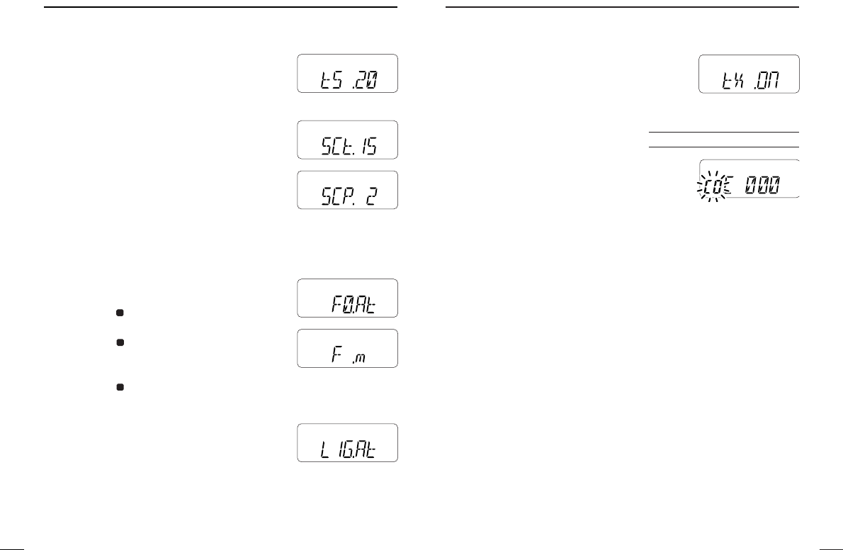
DDTransmission permission
Turns transmission permission ON and OFF.
This function can be set for each memory and
call channel, independently.
• tX .ON: Transmission is permitted. (default)
• tX .OF: Transmission is inhibited.
DDPager/Code squelch channel
Programs 3-digit ID code in channel “C0”
and individual or group call code in channel
“C1” to “C6” for the pager and code squelch
functions. See p. 41 for programming details.
*This item appears only when the optional UT-108 is installed and pager
or code squelch function is activated.
Optional UT-108 required
MR
F
TX
MR
F
TX
47
11 OTHER FUNCTIONS
DDTuning step
Selects tuning step from 5, 10, 12.5, 15, 20,
25 , 30 and 50 kHz.
DDScan pause timer
Selects the scan pause time from SCt.5,
SCt.10, SCt.15 and SCP. 2. When receiving
signals, the scan pauses according to the
scan pause time.
• SCt. 5/10/15 : Scan pauses for 5/10/15 sec.
(default: SCt.15)
• SCP. 2 : Scan pauses until signal dis-
appears. Resumes after 2 sec. from signal disap-
pearing.
DDFunction key timer
Selects [A•
FUNC
] effect timer from F0.At,
F1.At, F2.At, F3.At and F .m.
• F0.At : “ ” disappears immediately after
(default) secondary function is operated.
• F1/2/3.At : “ ” disappears after 1/2/3 sec.
from secondary function is oper-
ated.
• F .m : “ ” appears until [A•
FUNC
] is pushed again.
DDLCD backlight
Selects LCD backlight lighting condition from
auto, ON and OFF.
• LIG.At : Lights when any keys except
[PTT] is pushed. (default)
• LIG.ON : Lights continuously during the transceiver powered
ON.
• LIG.OF : Never lights.
F
F
F
MR
F
TX
MR
F
TX
MR
F
TX
MR
F
TX
MR
F
TX
MR
F
TX
50
11
OTHER FUNCTIONS
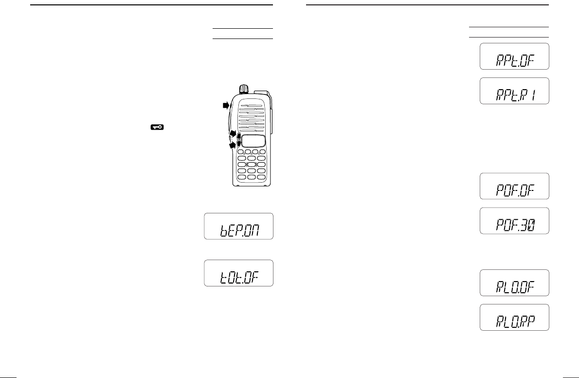
DDAuto repeater
The auto repeater function automatically turns
ON or OFF the duplex operation with speci-
fied shift direction and tone encoder, when the
operating frequency falls within or outside of
145.200–145.495, 146.610–146.995 and
147.000–147.395 MHz range. The offset and
repeater tone frequencies are not changed by
the auto repeater function, reset these frequencies, if necessary.
• RPt.OF : The auto repeater function is turned OFF.
• RPt.R1 : Activates for duplex only. (default)
• RPt.R2 : Activates for duplex and tone.
DDAuto power-off
The transceiver can be set to automatically
turn OFF after a specified period with beep in
which no key operations are performed.
• 30 min., 1 hour, 2 hours and OFF (default)
can be specified. The specified periods is re-
tained even when the transceiver is turned
OFF by the auto power-off function. To can-
cel the function, select “
POF.OF” in this set mode.
DDRepeater lock-out
Selects lockout type from repeater, busy and
OFF.
• RLO.RP : The repeater lockout is turned ON.
• RLO.bu : The busy lockout is turned ON.
• RLO.OF: Any lockout is not activated.
(default)
U.S.A. version only
MR
F
TX
AO
MR
F
TX
MR
F
TX
MR
F
TX
MR
F
TX
MR
F
TX
49
11 OTHER FUNCTIONS
‘‘Initial set mode
The initial set mode is accessed at power on and allows you to set
seldom-changed settings. In this way, you can “customize” trans-
ceiver operations to suit your preference and operating style.
DDEntering initial set mode
qTurn power on while [∫] and [√] are pushed.
wPush [∫] or [√] to select item.
eRotate [VOL] to select condition/value.
• To exit set mode, push [#•
ENT
].
DDKey-touch beep
Turns key-touch beep emission ON and OFF.
• Default: ON
DDTime-out timer
To prevent accidental prolonged transmission,
etc., the transceiver has a time-out timer. This
function cuts a transmission OFF after 1–30
min. of continuous transmission. This timer
can be cancelled.
• tOt.OF : The time-out timer is turned OFF. (default)
• tOt. 1–30 : The transmission cut OFF after the set period elapses.
AT
POWER ON
MR
F
TX
MR
F
TX
52
11
OTHER FUNCTIONS
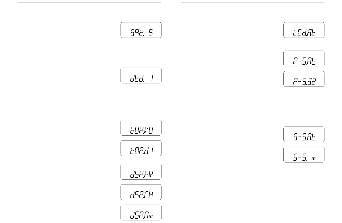
DDLCD contrast
Selects LCD contrast from auto and low.
• LCd.AT : Automatic (default)
• LCd.LO : Low contrast
DDPower save
Selects duty cycle for power save function
from auto, 1:32, 1:16, 1:8, 1:2 and OFF.
• P–S.At : Duty cycle changes automatically.
(default)
• P–S.32 : 1:32 (62.5 msec. standby: 2 sec.
power saved) duty cycle;
• P–S.16 : 1:16 (62.5 msec. standby: 1 sec.
power saved) duty cycle
• P–S. 8 :
1:8
(62.5 msec. standby: 500 msec. power saved)
duty cycle
• P–S. 2 :
1:2
(62.5 msec. standby: 125 msec. power saved)
duty cycle
• P–S.OF: The power save function turned OFF.
DDTuning speed acceleration
The tuning speed acceleration automatically
speeds up the tuning speed when pushing
and holding [∫] or [√], or rotating [VOL]
rapidly.*
• S–S.At : The tuning speed acceleration is
activated. (default)
• S–S. m : The tuning speed acceleration is
not activated.
*When tuning dial is assigned with [VOL].
MR
F
TX
MR
F
TX
MR
F
TX
MR
F
TX
MR
F
TX
51
11 OTHER FUNCTIONS
DDSquelch delay
Selects squelch delay from short and long to
prevent repeated opening and closing of the
squelch during reception of the same signal.
• Sqt. S: The squelch closes in short delay.
(default)
• Sqt. L: The squelch closes in long delay.
DDDTMF speed
The rate at which DTMF memories send indi-
vidual DTMF characters can be set to accom-
modate operating needs.
• 1: 100 msec. interval; 5.0 cps speed (default)
• 2: 200 msec. interval; 2.5 cps speed
• 3: 300 msec. interval; 1.6 cps speed
• 5: 500 msec. interval; 1.0 cps speed (cps=characters/sec.)
DDDial assignment
Selects [VOL] control action from AF volume
and tuning dial.
• tOP.VO : AF volume (default)
• tOP.dI : Tuning dial
DDDisplay type
Selects LCD indication type from frequency,
channel number and channel names.
• dSP.FR : Shows frequency (default)
• dSP.CH: Shows channel number*
• dSP.Nm: Shows channel names
*Memory channels can only be selected.
MR
F
TX
MR
F
TX
MR
F
TX
MR
F
TX
MR
F
TX
MR
F
TX
MR
F
TX
54
11
OTHER FUNCTIONS
‘‘CPU reset
The function display may occasionally display erroneous informa-
tion (e.g. when first applying power). This may be caused by exter-
nally by static electricity or other factors.
If this problem occurs, turn power OFF. After waiting a few seconds,
turn power ON again. If the problem persists, perform CPU reset-
ting operation as following procedure.
• Turn power on while [SQL] and [D•
CLR
] are
pushed.
CAUTION:
Resetting the CPU returns to all programmed
contents to their default settings.
AT
POWER ON
53
11 OTHER FUNCTIONS
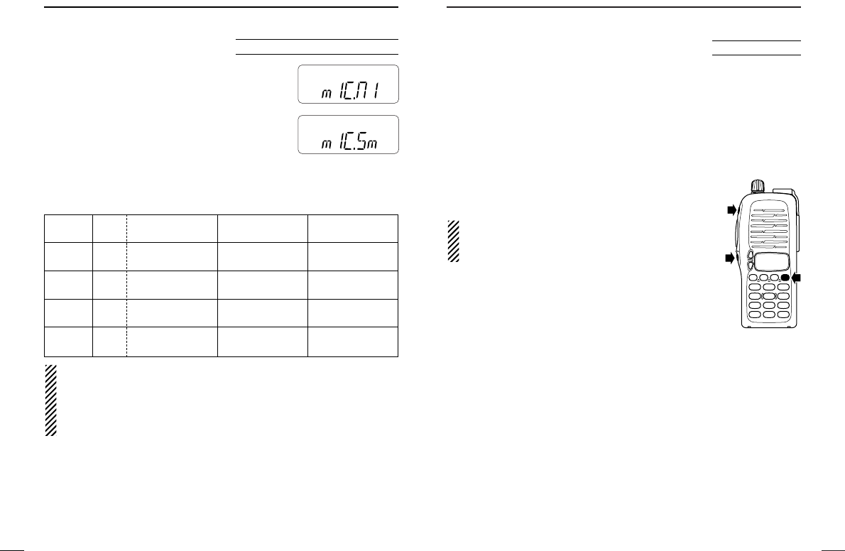
DDMic simple mode
This item turns the microphone simple mode
ON and OFF. Microphone simple mode is
used to change the function assignments for
keys in the optional HM-75A
REMOTE
-
CONTROL
SPEAKER
-
MICROPHONE
as below. This assign-
ment is convenient for 3-channel use of sim-
ple operation.
• mIC.N1 : Normal 1 (default)
• mIC.N2 : Normal 2
• mIC.Sm : Simple mode
NOTE:
Turn power OFF when connecting the HM-75A to the trans-
ceiver.
VFO mode cannot be selected via the microphone when SIM-
PLE mode is selected.
Optional HM-75A required
MR
F
TX
MR
F
TX
HM-75A Mode NORMAL1 NORMAL2 SIMPLE
key
[A] Freq. [B•
CALL
][SQL] [SQL]
CH Null
[B] Freq. VFO/Memory VFO/Memory [B•
CALL
]
CH Null Null
[∫]Freq. Freq. Up Freq. Up MR-00CH
CH Memory CH Up Memory CH Up
[√]Freq. Freq. Down Freq. Down MR-01CH
CH Memory CH Down Memory CH Down

56
13
OPTIONAL UNIT
DOptional UT-108 installation
qRemove the optional
connecter access cover
(named 2251 OPT
sheet).
•Insert a screwdriver into
the hollow of the chassis,
then lift and take away
the cover. (The cover
can not be used again.)
WARNING!
NEVER attempt to remove the optional connector cover
using your finger nails, this may result in injury.
wAttach the optional unit. Insert the connector tightly to avoid a
bad contact.
eRemove the paper back-
ing of 2251 OPT sheet
supplied as an acces-
sory.
rAttach the new 2251
OPT sheet to the service
window.
tProgram the necessary
information from the
transceivers key pads or
using the cloning soft-
ware, before operation.
55
12 CLONING
Cloning allows you to quickly and easily transfer the programmed
contents from one transceiver to another transceiver; or, data from
a PC to a transceiver using the optional CS-V8
CLONING SOFTWARE
.
DTransceiver-to-transceiver cloning
qConnect the OPC-474
CLONING CABLE
with
adaptor plugs to the [SP] jack of the master and sub trans-
ceivers.
• The master transceiver is used to send data to the sub transceiver.
wWhile pushing [A•
FUNC
]+[Y], turn power ON to enter cloning
mode (master transceiver only— power ON only for sub trans-
ceiver).
• “CLONE” appears and the transceivers enter the clone standby
condition.
ePush [PTT] on the master transceiver.
• “CL” appears in the master transceiver’s display and two digit num-
bers show that data is being transferred to the sub transceiver.
• “CL IN” appears automatically in the sub transceiver’s display and
two digit numbers show that data is being received from the master
transceiver.
rWhen cloning is finished, turn power OFF, then ON again to exit
cloning mode.
DCloning using a PC
Please refer to the HELP file that comes with CS-V8
CLONING
SOFTWARE
.
NOTE: DO NOT push the [PTT] on the sub transceiver during
cloning. This will cause a cloning error.
AT
POWER ON
q
w
e
r

58
15
OPTIONS
57
14 SPECIFICATIONS
DD General
• Frequency range :
USA 144–148 MHz (Tx), 136–174 MHz* (Rx)
Asia/CSA 136–174 MHz* (Tx/Rx)
*Guaranteed 144–148 MHz range only.
• Operatable temp. range : –10˚C to +60˚C; +14˚F to +140˚F
• Frequency stability : ±10 ppm (–10˚C to +60˚C)
• Antenna connector : BNC (50 Ω)
• Power supply requirement : 7.2 V DC (6–10.3 V DC acceptable; Icom’s bat-
tery pack only)
• Current drain (at 7.2 V DC) :
Transmit at 5.5 W Less than 2.0 A
at 0.5 W Less than 0.7 A
Receive at max. AF Less than 250 mA
Stand-by Less than 70 mA
Power saved Less than 20 mA
• No. of memory channels :
107 (incl. 1 call and 6 programmed scan edges)
• Tuning steps : 5, 10, 12.5, 15, 20, 25, 30 and 50 kHz
• Dimensions : 54(W)×132(H)×35(D) mm
(projections not included) ; 21⁄8(W)×53⁄16(H)×13⁄8(D) in
• Weight (approx.) : 350 g; 12.3 oz (with BP-222)
190 g; 6.7 oz (without battery pack)
DD Transmitter
• Modulation systems : Variable reactance frequency modulation
• Output power (at 7.2 V DC) : 5.5 W (High), 0.5 W (Low)
• Max. frequency deviation : ±5.0 kHz
• Spurious emissions : Less than –60 dB
• External mic. connector : 3-conductor 2.5 (d) mm (1⁄10″); 2.2 kΩ
DD Receiver
• Receiving system : Double conversion superheterodyne system
• Intermediate frequencies : 1st: 21.7 MHz, 2nd: 450 kHz
•
Sensitivity (at 12 dB SINAD)
: 0.16 µV typ.
• Squelch sensitivity : 0.1 µV typ.
• Selectivity : 65 dB typ.
• Intermodulation rejection : 65 dB typ.
•
Spurious & image rejection
: 75 dB typ.
• Audio output power : More than 0.3 W at 10% distortion with an
(at 7.2 V DC) 8 Ωload
•
External speaker connector
: 2-conductor 3.5 (d) mm(1⁄8″); 8 Ω
DDBATTERY PACKS
*1Operating periods are calculated under the following conditions:
Tx:Rx:standby=5:5:90, power save function: auto setting, is activated
*2Operate with the LOW output power selection is recommended.
DDCHARGER
•BC-144 (#11)
DESKTOP CHARGER
+ BC-145
AC ADAPTER
For rapid charging. Charging time: 1.5 to 2 hrs.
•BC-137 (#11)
BATTERY CHARGER
+ BC-122
AC ADAPTER
For regular charging. Charging time: 15 hrs.
•BC-146
BATTERY CHARGER
+ BC-147
AC ADAPTER
.
For regular charging. Charging time: 18.5 hrs.
• BC-121
MULTI
-
CHARGER
+ AD-94 (#11)
CHARGER ADAPTER
(6 pcs.)
For rapid charging of up to 6 battery packs simultaneously.
Charging time: 1.5 to 2 hrs.
• BC-119
DESKTOP CHARGER
+ AD-94 (#11)
CHARGER ADAPTER
For rapid charging of battery packs. Charging time: 1.5 to 2 hrs.
DDINTERNAL UNIT
• UT-108
DTMF DECODER UNIT
Provides pager and code squelch capabilities.
DDOTHER OPTIONS
• HM-54/HM-46L/HM-75A/HM-131L
SPEAKER
-
MICROPHONES
• HM-128L
EARPHONE
-
MICROPHONES
• HS-51
HEADSET
• MB-68/MB-74
BELT CLIPS
• CS-V8
CLONING SOFTWARE
+ OPC-478
CLONING CABLE
For memory contents programming by PC editing.
• OPC-474
CLONING CABLE
For cloning between transceivers.
• SP-13
EARPHONE
Battery Voltage Capacity Output Operating
Pack Power Period*1
BP-208*2Battery case for R6 (AA) 5.5 W —
×6 alkaline or Ni-Cd cells
BP-209 7.2 V 1100 mAh 5.5 W 7.5 hrs.
BP-210 7.2 V 1650 mAh 5.5 W 11 hrs.
BP-222 7.2 V 600 mAh 5.5 W 4 hrs.