ICOM orporated IC-V8000 Amateur Scanning Transceiver User Manual Manual
ICOM Incorporated Amateur Scanning Transceiver Manual
UserManual.wiki
>
ICOM orporated
>
IC V8000 User Manual
Manual
Navigation menu
Upload a User Manual
Namespaces
Wiki Guide
HTML
PDF
Info
Views
User Manual
Discussion / Help
Navigation
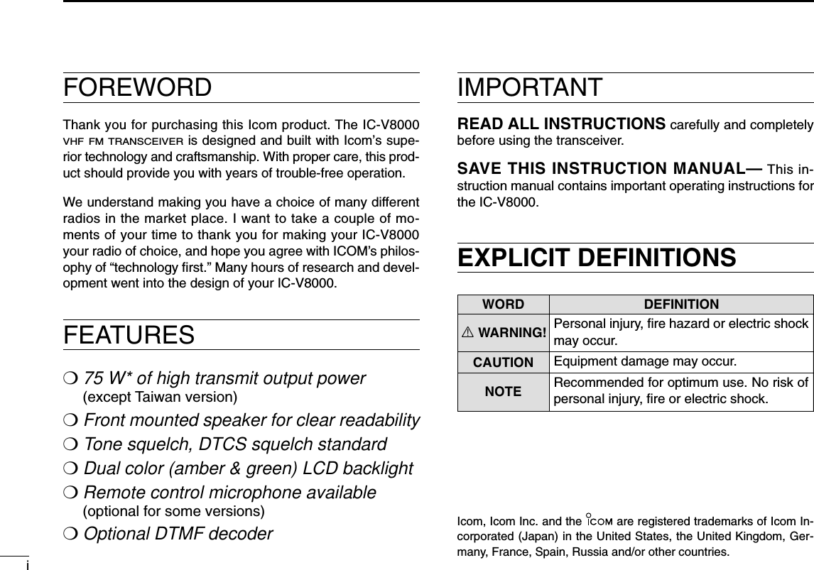
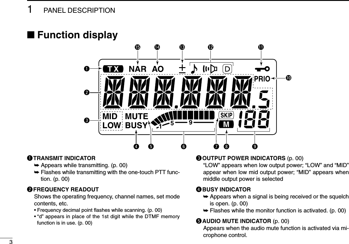
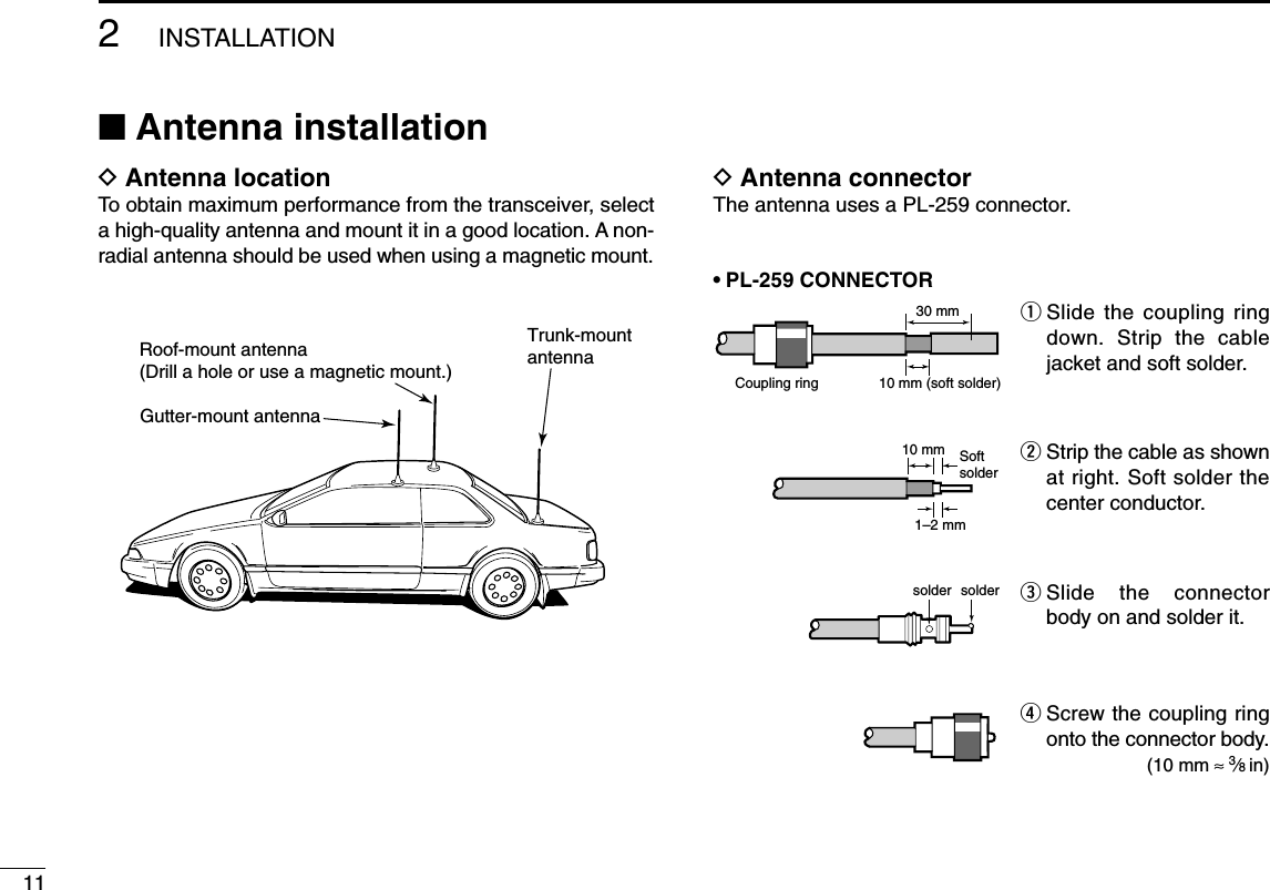
![■Front panelqPOWER SWITCH [PWR]Turns power ON and OFF when pushed for 1 sec.wMEMORY/CALL•PRIORITY SWITCH [M/CALL(PRIO)](p. 00)➥Push to selects and toggles memory, call and weatherchannel* mode.*Weather channels available for USA versions only.➥Starts priority scan when pushed for 1 sec. eMICROPHONE CONNECTORConnects the supplied microphone. (p. 00)rSQUELCH CONTROL [SQL]Varies the squelch level. (p. 00)• The RF attenuator activates and increases the attenuation whenrotated clockwise to the center position and further.tVOLUME CONTROL [VOL]Adjusts the audio level. (p. 00)OPTBANKV/MHzSCANLOWDUPMONIANMSETLOCKPWRS.MWMWT-SCANTONEPRIOM/CALLtFunction display (p. 00)qweryuioSpeaker!0!1!2!31PANEL DESCRIPTION1234567891011121314151617181920211](https://usermanual.wiki/ICOM-orporated/IC-V8000/User-Guide-201766-Page-4.png)
![21PANEL DESCRIPTION123456789101112131415161718192021yBANK•OPTION SWITCH [BANK(OPT)]➥Selects memory memory bank when pushed. (p. 00)➥Push for 1 sec. to turn the DTMF decoder ON and OFFwhen the optional UT-108 is installed. (p. 00)uSET•LOCK SWITCH [SET(LOCK)]➥Selects set mode when pushed.➥Switches the lock function ON and OFF when pushedfor 1 sec. (p. 14)iTUNING DIAL [DIAL]Selects the memory channel (p. 00), call channel (pgs. 00,00, 00), the contents of the set mode display and thescanning direction (p. 00).oMEMORY WRITE SWITCH [MW(S.MW)]➥Enter to memory edit mode when pushed. (p. 00)➥Program into the selected memory channel whenpushed for 1 sec. (p. 00)•Continue to hold the switch to increment the memory channelautomatically.!0 MONITOR•CHANNEL NAME SWITCH [MONI(ANM)]➥Push to switch the monitor function ON and OFF. (p. 00)➥Push for 1 sec. to toggle the frequency indication andchannel name indication. (p. 00)!1 OUTPUT POWER SWITCH [LOW(DUP)]➥Each push changes the output power selection. (p. 00)➥Select DUP–, DUP+ and simplex operation whenpushed for 1 sec. (p. 00)!2 TONE/TONE SCAN SWITCH [TONE(T-SCAN)]➥Each push selects a tone function. (p. 00)•Tone encoder, pocket beep, tone squelch or tone functionOFF can be selected.➥Push for 1 sec. to start/stop the tone scan function.(p. 00)!3 VFO/MHz TUNING•SCAN SWITCH [V/MHz(SCAN)]➥Selects and toggles VFO mode and 1 MHz or 100 kHztuning when pushed. (p. 00)•Cancels a scan when pushed during scan.➥Starts scan when pushed for 1 sec. (p. 00)DMicrophone connector (front panel view)q+8 V DC output (Max. 10 mA)wChannel up/downe8 V control INrPTTtGND (microphone ground)yMIC (microphone input)uGNDiData INqi](https://usermanual.wiki/ICOM-orporated/IC-V8000/User-Guide-201766-Page-5.png)
![51PANEL DESCRIPTION■Rear panelqSPEAKER JACK [SP]Accepts an 8 Ωspeaker.•Audio output power is more than 2.0 W.wPOWER RECEPTACLE [DC13.8V]Accepts 13.8 V DC ±15% with the supplied DC powercable.☞NOTE: DO NOT use a cigarette lighter socket as apower source when operating in a vehicle. The plugmay cause voltage drops and ignition noise may be su-perimposed onto transmit or receive audio.eCOOLING FANrANTENNA CONNECTOR [ANT]Connects a 50 Ωantenna with a PL-259 connector and a50 Ωcoaxial cable.qwer](https://usermanual.wiki/ICOM-orporated/IC-V8000/User-Guide-201766-Page-8.png)
![61PANEL DESCRIPTION123456789101112131415161718192021■Microphone (HM-133V*)qVFO/LOCK SWITCH [VFO/LOCK]➥Push to select VFO mode. (p. 00)➥Push for 1 sec. to switch the lock function ON and OFF.(p. 00)wPTT SWITCH➥Push and hold to transmit; release to receive.➥Switches between transmitting and receiving while theone-touch PTT function is in use. (p. 00)eUP/DOWN SWITCHES [Y]/[Z]➥Push either switch to change memory channel, callchannel, set mode contents, etc. (pgs. 00, 00)➥Push either switch for 1 sec. to start scanning. (p. 00)rACTIVITY INDICATOR➥Lights red while any key, except [FUNC] and [DTMF-S],is pushed, or while transmitting.➥Lights green while the one-touch PTT function is in use.tKEYPAD (p. 00)yFUNCTION INDICATOR➥Lights orange while [FUNC] is activated—indicates thesecondary function of switches can be accessed.➥Lights green when [DTMF-S] is activated—DTMF sig-nals can be transmitted with the keypad.uFUNCTION SWITCH [FUNC] (p. 00)iDTMF MEMORY SELECT SWITCH [DTMF-S] (p. 00)oFUNCTION SWITCHES [F-1]/[F-2] (p. 00)Assign your desired key function from the front panelswitches.•Default settings are [LOW(DUP)] for [F-1] and [TONE(T-SCAN)]for [F-2] ([T-SCAN] when pushed and held).!2BANK/OPTION SWITCH [BANK/OPTION] ➥Push to select memory bank. (p. 00)➥Push for 1 sec. to activate the installed optional unit.(p. 00)yMEMORY/CALL SWITCH [MR/CALL]➥Push to select memory mode. (p. 00)➥Push for 1 sec. to select call channel. (p. 00)qertMic elementyuio!0!1w*A different microphonemay be supplied de-pending on version.](https://usermanual.wiki/ICOM-orporated/IC-V8000/User-Guide-201766-Page-9.png)
![71PANEL DESCRIPTION■Microphone keypadKEY FUNCTIONSECONDARY FUNCTION (after )OTHER FUNCTIONSSwitches between opening and closing thesquelch.Starts and stops scanning. (p. 00)Starts and stops priority watch. (p. 00)Selects high output power. (p. 00)Selects mid. output power. (p. 00)Selects low output power (p. 00)Selects minus duplex operation. (p. 00)Selects plus duplex operation. (p. 00)Selects simplex operation. (p. 00)No primary function.Switches between frequency indication andmemory names indication. (p. 00)Starts and stops tone scanning. (p. 00)Turns the one-touch PTT function ON andOFF. (p. 00)Turns the DTCS squelch ON. (p. 00)Turns the DTCS pocket beep function ON.(p. 00)Turns the DTMF memory encoder functionON. (p. 00)Turns the subaudible tone encoder ON.(p. 00)Turns the CTCSS pocket beep functionON. (p. 00)Turns the tone squelch function ON.(p. 00)Sends a 1750 Hz tone signal while pushingand holding. (p. 00)After :Transmit the appropriateDTMF code or push [0] to [9],[A] to [D] to transmit theDTMF memory contentswhen the DTMF memory en-coder is activated. (p. 00)](https://usermanual.wiki/ICOM-orporated/IC-V8000/User-Guide-201766-Page-10.png)
![81PANEL DESCRIPTION123456789101112131415161718192021➥Clears a digit before entry. (p. 00)➥Cancels the scan, priority watch orDTMF memory function. (pgs. 00, 00)➥Exit set mode (p. 00)➥Increases the set mode selection orderafter entering set mode. (p. 00)Enters set mode and advances the setmode selection.➥Sets the keypad for numeral input(p. 00)➥Decreases the set mode selection orderafter entering set mode.Adjusts the squelch level increments.(p. 00)No primary function.Adjusts the squelch level decrement.➥Writes memory contents into the callchannel. (p. 00)➥Advances the memory channel numberwhen continuously pushed after pro-gramming is completed. (p. 00)DTMF memory OFF.Turns the subaudible tone encoder, pocketbeep or CTCSS/DTCS tone squelch OFF.(pgs. 00, 00, 00)Mutes the audio. (p. 00)•Mute function is released when any operationis performed.Locks the digit keys on the keypad (includ-ing the A to D, # and Mkeys. (p. 14)Sends a 1750 Hz tone signal for 0.5 sec.(p. 00)After :Transmits the appropriateDTMF code. (p. 00)[A] to [D] transmit DTMFmemories. (p. 00)KEY FUNCTIONSECONDARY FUNCTION (after )OTHER FUNCTIONS](https://usermanual.wiki/ICOM-orporated/IC-V8000/User-Guide-201766-Page-11.png)
![123SETTING A FREQUENCY123456789101112131415161718192021■PreparationDTurning power ON/OFF➥Push [PWR] for 1 sec. toturn power ON or OFF.DVFO mode selectionThe transceiver has 2 basic operating modes: VFO mode andmemory mode.➥Push [V/MHz(SCAN)] toselect VFO mode.➥Push [VFO/LOCK] to select VFO mode.■Using the tuning dialqRotate the tuning dial to set the frequency.•If VFO mode is not selected,push [V/MHz(SCAN)] to selectVFO mode.•The frequency changes ac-cording to the selected tuningsteps. (p. 00)wTo change the frequency in 1 MHz (10 MHz for some ver-sions) steps, push [V/MHz(SCAN)], then rotate the tuningdial.•Pushing [V/MHz(SCAM)] for1 sec. starts scan function. Ifscan starts, push[V/MHz(SCAN)] again to can-cel it.The display shows that the 1 MHz tuning step is selected.Tunig dial[V/MHz(SCAN)]VFO/LOCKPush [V/MHz(SCAN)]Push [PWR] for 1sec.Note that in this manual, sections beginning with a micro-phone icon (as above), designate operation via the HM-133V microphone.](https://usermanual.wiki/ICOM-orporated/IC-V8000/User-Guide-201766-Page-15.png)
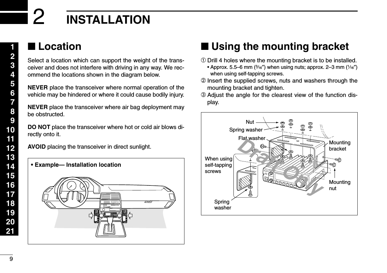
![133SETTING A FREQUENCY■Using the keypadThe frequency can be directly set via numeral keys on the mi-crophone.zPush [VFO/LOCK] to VFO mode, if necessary.xPush [ENTC] to activate the keypad for digit input.cPush 6 keys to input a frequency.•When a digit is mistakenly input, push [ENTC] to clearthe input, then repeat input from the 1st digit.•Pushing [CLRA] clears input digits and retrieves thefrequency.■Using the [Y]/[Z] keys➥Push [Y] or [Z] to select the desired frequency.•Pushing [Y] or [Z] for more than 0.5 sec. activates ascan. If scan starts, push [Y] or [Z] again to cancel it.YZPushPushPushPush[EXAMPLE]: Setting frequency to 145.3625 MHz.ENTC](https://usermanual.wiki/ICOM-orporated/IC-V8000/User-Guide-201766-Page-16.png)
![143SETTING A FREQUENCY123456789101112131415161718192021■Tuning step selectionTuning steps are the minimum frequency change incrementswhen you rotate the tuning dial or push [Y]/[Z] on the micro-phone. The following tuning steps are available.•5 kHz •10 kHz •12.5 kHz •15 kHz•20 kHz •25 kHz •30 kHz •50 kHz☞NOTE: For convenience, select a tuning step that matchesthe frequency intervals of repeaters in your area.qPush [V/MHz(SCAN)] to se-lect VFO mode, if neces-sary.wPush [SET(LOCK)] to enterset mode.ePush [SET(LOCK)] or[MW(S.MW)] several timesuntil “TS” appears as shownbelow.•Cancel the DTMF memoryfunction in advance, if neces-sary.rRotate the tuning dial to se-lect the desired tuning step.tPush [V/MHz(SCAN)] to exitset mode.1Push [VFO/LOCK] to select VFO mode, ifnecessary.2Push [SETB] to enter set mode.3Push [SETB] or [ENTC] several times until“TS” appears.4Push [Y] or [Z] to select the desired tuningstep.5Push [CLRA] to exit set mode.VFO/LOCK[SET(LOCK)]15 kHz tuning step[MW(S.MW)]Tuning dialUSINGSET MODE](https://usermanual.wiki/ICOM-orporated/IC-V8000/User-Guide-201766-Page-17.png)
![153SETTING A FREQUENCY■Lock functionsTo prevent accidental channel changes and unnecessaryfunction access, use the lock function. The transceiver has 2different lock functions.DFrequency lockThis function locks the tuning dial and switches electronicallyand can be used together with the microphone lock function.➥Push [SET(LOCK)] for1 sec. to turn the lock func-tion ON and OFF.•[PTT], [MONI(ANM)], [VOL]and [SQL] can be used whilethe channel lock function is inuse. Also, TONE-1, TONE-2,DTMF tones or DTMF mem-ory contents can be transmit-ted from the microphone.➥Push [VFO/LOCK] for 1 sec. to switch thelock function ON and OFF.DMicrophone keypad lockThis function locks the microphone keypad.➥Push [FUNC] then [SQLZD(16KEY-L)] toswitch the microphone keypad lock functionON and OFF.•[PTT], [VFO/LOCK], [MR/CALL], [BANK/OPTION],[Y], [Z], [F-1], [F-2], [DTMF-S] and [FUNC] on themicrophone can be used.•All switches on the transceiver can be used.•The keypad lock function is released when thepower is turned OFF then ON again.16KEY-LVFO/LOCKPush [SET(LOCK)] for 1 sec.Appears](https://usermanual.wiki/ICOM-orporated/IC-V8000/User-Guide-201766-Page-18.png)
![164BASIC OPERATION123456789101112131415161718192021■ReceivingqPush [PWR] for 1 sec. to turn power ON.wSet the audio level.➥Push [MONI(ANM)] to open the squelch.➥Rotate the [VOL] control to adjust the audio output level.➥Push [MONI(ANM)] again to close the squelch.eSet the squelch level.➥Rotate [SQL] fully counterclockwise in advance.➥Rotate [SQL] clockwise until the noise just disappears.➥When interference is received, rotate [SQL] clockwiseagain for attenuator operation.rSet the operating frequency. (pgs. 00, 00)tWhen receiving a signal on the set frequency, squelchopens and the transceiver emits audio.•“BUSY” appears and the S/RFindicator shows the relativesignal strength for the re-ceived signal.✔CONVENIENT!The squelch level can also be adjusted with[SQLYD(MUTE)] and [SQLZ#(16KEY-L)] on the mi-crophone.■Monitor functionThis function is used to listen to weak signals without disturb-ing the squelch setting or to open the squelch manually evenwhen mute functions such as the tone squelch are in use.➥Push [MONI(ANM)] to openthe squelch.•“BUSY” flashes•Push [MONI(ANM)] again tocancel the function.➥Push [MONI1] to open the squelch.•Push [MONI1] again to cancel the function.MONI1Push [MONI(ANM)]SQLYDSQLZ#Appears when receiving a signal.](https://usermanual.wiki/ICOM-orporated/IC-V8000/User-Guide-201766-Page-19.png)
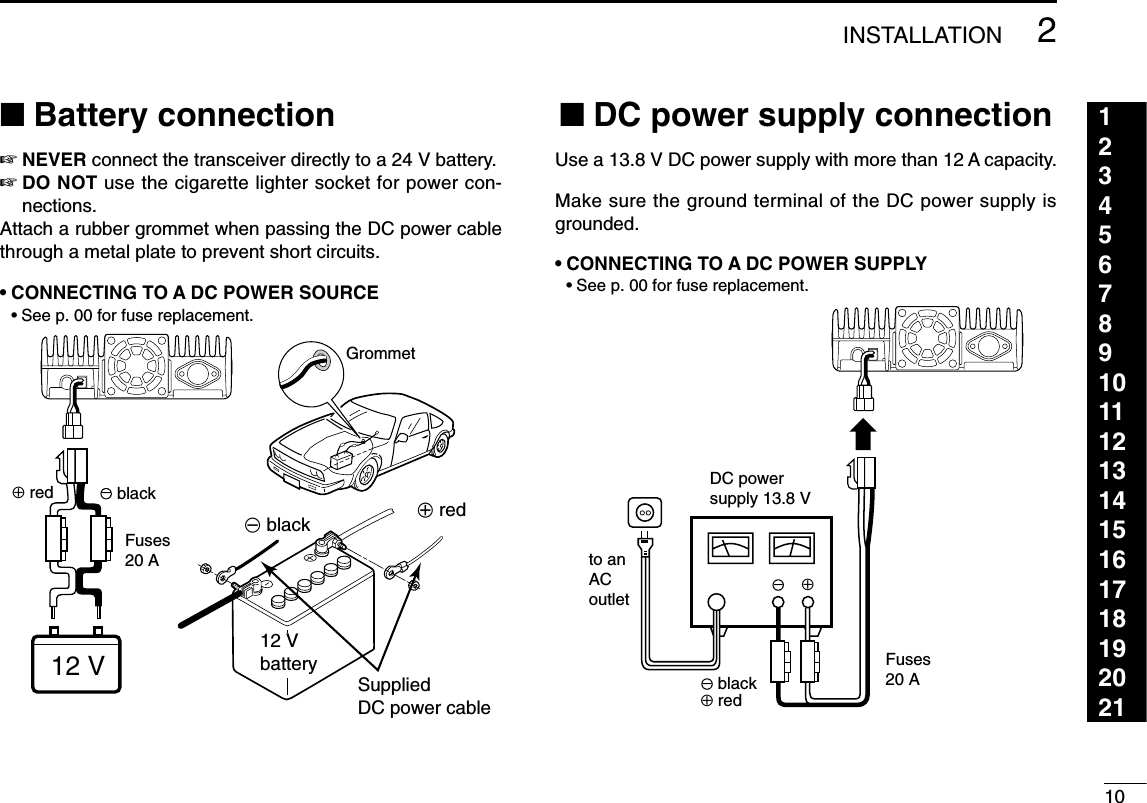
![174BASIC OPERATION■Audio mute functionThis function temporarily mutes the audio without disturbingthe volume setting.zPush [FUNC] then [SQLYD(MUTE)] to muteaudio signals.•“MUTE” appears.xPush [CLRA] (or any other key) to cancel thefunction.•“MUTE” disappears.■Squelch attenuatorThe transceiver has an RF attenuator related to the squelchlevel setting. Approx. 10 dB attenuation is obtained at maxi-mum setting.➥Rotate [SQL] clockwise past the 12 o’clock position to ac-tivates the squelch attenuator.•Attenuation level can be adjusted up to 10 dB (approx.) between12 o’ckloc and fully clockwise position.•When setting the squelch via from the microphone, the level “19”or larger setting to acitivates the squelch attenuator.■Transmitting☞NOTE: To prevent interference, listen on the channel be-fore transmitting by pushing [MONI(ANM)] or [MONI1] onthe microphone.qSet the operating frequency. (pgs. 00, 00)•Select output power if desired. See section at right for details.wPush and hold [PTT] to transmit.•“$” appears.•The S/RF indicator shows the output power selection.•A one-touch PTT function is available. See p. 00 for details.eSpeak into the microphone using your normal voice level.•DO NOT hold the microphone too close to your mouth or speaktoo loudly. This may distort the signal.rRelease [PTT] to return to receive.CAUTION: Transmitting without an antenna will damagethe transceiver.AppearsMUTE](https://usermanual.wiki/ICOM-orporated/IC-V8000/User-Guide-201766-Page-20.png)
![184BASIC OPERATION123456789101112131415161718192021■Selecting output powerThe transceiver has 4* output power levels to suit your oper-ating requirements. Low output powers during short-distancecommunications may reduce the possibility of interference toother stations and will reduce current consumption.*The Thailand and Taiwan versions have only 2 levels.Push [LOW(DUP)] several times to select the output power.•The output power can be changed while transmitting. *approx.The microphone can also be used to select output power.➥Push [HIGH4] for high output power; [MID5] formiddle high output power; and [LOW6] for lowoutput power.•The output power CANNOT be changed via the mi-crophone while transmitting.■One-touch PTT functionThe PTT switch can be operated as a one-touch PTT switch(each push switches transmit/receive). Using this function youcan transmit without pushing and holding the PTT switch.To prevent accidental, continuous transmissions with thisfunction, the transceiver has a time-out timer. See p. 00 fordetails.zPush [FUNC] then [PRIO3(PTT-M)] to turn theone-touch PTT function ON.•The activity indicator lights green.xPush [PTT] to transmit and push again to re-ceive.•Two beeps sound when transmission is started and along beep sounds when returning to receive.•“$” flashes when transmitting with the one-touchPTT function.cPush [FUNC] then [PRIO3(PTT-M)] to turn theone-touch PTT function OFF.•The activity indicator goes out.PTT-MHIGH4MID5LOW6S/RF INDICATOR POWER OUTPUTThailand Taiwan70 W 10 W 25 W25 W* N/A N/A10 W* N/A N/A5W* 5W* 5W*High:Mid.:Mid. Low:Low:](https://usermanual.wiki/ICOM-orporated/IC-V8000/User-Guide-201766-Page-21.png)
![19REPEATER OPERATION1234567891011121314151617181920215■Accessing a repeaterqSet the receive frequency (repeater output frequency).(pgs. 00–00)wPush [LOW(DUP)] for 1 sec., one or two times, to selectminus duplex or plus duplex.• “–” or “+” appears to indicatethe transmit frequency forminus shift or plus shift, re-spectively.•When the auto repeater func-tion is turned ON (available forthe USA version only), stepswand eare not necessary.(p. 00)ePush [TONE(T-SCAN)] several times to turn ON the sub-audible tone encoder, according to repeater requirements.•“” appears •88.5 Hz is set to default; refer to p. 00 for tone frequency settings.•When the repeater requires a different tone systems, see p. 00.rPush and hold [PTT] to transmit.•The displayed frequency automatically changes to the transmitfrequency (repeater input frequency).•If “OFF” appears, confirm that the offset frequency (p. 00) is setcorrectly.tRelease [PTT] to receive.yPush [MONI(ANM)] to check weather the other station’stransmit signal can be received directly.uTo return to simplex operation, push [LOW(DUP)] for1 sec., once or twice, to clear the “–” or “+” indicator.iTo turn OFF the subaudible tone encoder, push [TONE(T-SCAN)] several times until no tone indicators appear.zSet the receive frequency (repeater output fre-quency). (pgs. 00–00)xPush [DUP–7] to select minus duplex; push[DUP+ 8] to select plus duplex.cPush [FUNC] then [DUP–7(TONE)] to turn ONthe subaudible tone encoder according to re-peater requirements.•Refer to p. 00 for the tone setting.•When the repeater requires a different tone system,see p. 00.vPush and hold [PTT] to transmit.bRelease [PTT] to receive.nPush [MONI1] to check weather the other sta-tion’s transmit signal can be received directly.mTo return to simplex operation, push [SIMP9].,To turn OFF the subaudible tone encoder, push[FUNC] then [ENTC(T-OFF)].DUP–7DUP+8SIMP9Either “–” or “+” appears.](https://usermanual.wiki/ICOM-orporated/IC-V8000/User-Guide-201766-Page-22.png)
![■Subaudible tones(Encoder function)DSubaudible tonesqSelect the mode/channel you wish to set the subaudibletones to, such as VFO mode or memory/call channel.wPush [SET(LOCK)] until “” and “rt” appears; or until “”and “Ct” appears for tone squelch or pocket beep use.•Push [MONI(ANM)] to reverse the order of selection.•Cancel the DTMF memory encoder function in advance, if nec-essary. (p. 00)eRotate the tuning dial to select and set the desired sub-audible frequency.rPush [V/MHz(SCAN)] to exit set mode.☞NOTE: The subaudible tone encoder frequency can be setin a memory channel temporarily. However, the set con-tents are cleared once the memory/call mode is selected.To store the tone frequency permanently, overwrite thechannel information.zSet the mode/channel you wish to set the sub-audible tone encoder frequency to, such asVFO mode or memory/call channel.•The subaudible tone frequency is independently pro-grammed into each mode or channel.xPush [SETB] until “” and “rt” appears; or until“” and “Ct” appears for tone squelch or pocketbeep use.•Pushing [ENTC] reverses the order of selection.•Cancel the DTMF memory encoder function in ad-vance, if necessary. (p. 00)cPush [Y] or [Z] to select and set the desiredsubaudible tone frequency.•Push and hold [Y]/[Z] to change the above tonescontinuously.vPush [CLRA] to exit set mode.•Subaudible tone frequency list (unit: Hz)67.069.371.974.477.079.782.585.488.591.594.897.4100.0103.5107.2110.9114.8118.8123.0127.3131.8136.5141.3146.2151.4156.7159.8162.2165.5167.9171.3173.8177.3179.9183.5186.2189.9192.8196.6199.5203.5206.5210.7218.1225.7229.1233.6241.8250.3254.1SETBUSINGSET MODE205REPEATER OPERATION123456789101112131415161718192021The display shows that an88.5 Hz subaudible CTCSStone frequency is set.](https://usermanual.wiki/ICOM-orporated/IC-V8000/User-Guide-201766-Page-23.png)
![DDTMF tones➥Push [DTMF-S], then push the keys of the de-sired DTMF digits.•The function indicator lights green.•0–9, A–D, M(E) and #(F) are available.•Cancel the DTMF memory encoder function in ad-vance, if necessary. (p. 00)•Push [DTMF-S] again to return the keypad to nor-mal function control.•The transceiver has 14 DTMF memory channelsfor autopatch operation. See p. 00 for details.D1750 Hz toneThe microphone has 1750 Hz tone capability,used for ring tone when calling, etc.zPush [FUNC].•The mode indicator lights orange.xPush [TONE-1] to transmit a 1750 Hz tone callsignal for 0.5 sec.; push and hold [TONE-2] totransmit a 1750 Hz tone call signal for an arbi-trary period.•The mode indicator goes out automatically.■Offset frequencyWhen communicating thorough a repeater, the transmit fre-quency is shifted from the receive frequency by an amountdetermined by the offset frequency.qPush [SET(LOCK)] to enterset mode.wPush [SET(LOCK)] until “±”and offset frequency ap-pear.eRotate the tuning dial to setthe desired offset frequency.rPush [V/MHz(SCAN)] to exitset mode.USINGSET MODETONE-1TONE-2DTMF-S215REPEATER OPERATION](https://usermanual.wiki/ICOM-orporated/IC-V8000/User-Guide-201766-Page-24.png)
![225REPEATER OPERATION123456789101112131415161718192021■Auto repeater (USA version only)The USA version automatically activates the repeater settings(DUP– or DUP+ and tone encoder ON/OFF) when the operatingfrequency falls within the general repeater output frequencyrange and deactivates them when outside of the range.DSetting the auto repeater function ON/OFFqPush [PWR] to turn power OFF.wWhile pushing [SET(LOCK)], turn power ON to enter initialset mode.ePush [SET(LOCK)] several times until the “RPT” displayappears as shown below.rRotate the tuning dial to turn the repeater lockout functionto “R1,” “R2” or OFF.•“R1”: auto repeater is ON, tone encoder is OFF.•“R2”: auto repeater is ON, tone encoder is ON.tPush [PWR] to exit initial set mode.DFrequency range and offset directionAuto repeater function is turned OFF.Auto repeater function is ON,tone encoder is ON.While pushing [SET(LOCK)], turn power ON.USINGINITIAL SET MODEFrequency range Duplex direction145.200–145.495 MHz “–” appears146.610–146.995 MHz147.000–147.395 MHz “+” appears](https://usermanual.wiki/ICOM-orporated/IC-V8000/User-Guide-201766-Page-25.png)
![■Repeater lockoutThis function helps prevent interference to other stations byinhibiting your transmission when a signal is received. Thetransceiver has two inhibiting conditions, repeater and busy.qPush [PWR] to turn power OFF.wWhile pushing [SET(LOCK)], turn power ON to enter initialset mode.ePush [SET(LOCK)] several times until the “RLO” displayappears as shown below.rRotate the tuning dial to turn the repeater lockout functionto “RP,” “BU” or OFF.•“RP”: Transmit is inhibited when the tone squelch is closed.•“BU”: Transmit is inhibited when a signal is received.tPush [PWR] to exit initial set mode.■Reversed duplex modeWhen the reversed duplex mode is selected, the receive fre-quency shifts. (Transmit frequency shifts in normal duplex mode.)Each receive and transmit frequency is shown in the tablebelow with the following conditions;Input frequency : 145.30 MHzDirection : – (negative)Offset frequency : 0.6 MHzqPush [SET(LOCK] to enter set mode.wPush [SET(LOCK)] several times until the “REV” displayappears as shown below.rRotate the tuning dial to turn the repeater lockout functionto ON or OFF.tPush [V/MHz(SCAN)] to exit set mode.Reverse duplex mode is turned ON.USINGSET MODEAuto repeater function is turned OFF.Auto repeater function is ON,tone encoder is ON.While pushing [SET(LOCK)], turn power ON.USINGINITIAL SET MODEReversed OFF ONRx frequency 145.30 MHz 144.70 MHzTx frequency 144.70 MHz 145.30 MHz235REPEATER OPERATION](https://usermanual.wiki/ICOM-orporated/IC-V8000/User-Guide-201766-Page-26.png)
![246MEMORY OPERATION123456789101112131415161718192021■General descriptionThe transceiver has 207 memory channels including 6 scanedge memory channels (3 pairs), and 1 call channel. Each ofthese channels can be individually programmed with operat-ing frequency (p. 00), duplex direction (p. 00), subaudibletone encoder or tone squelch and its tone frequency (pgs. 00,00) and skip information.* (p. 00) In addition, a total of 10 memory banks, A to J, are availablefor making groups with usage, etc.*except for scan edge memory channels.■Memory channel selectionDUsing the tuning dialqPush [M/CALL(PRIO)]once or twice to selectmemory mode.•“M” indicator appearswRotate the tuning dial toselect the desired mem-ory channel.•Programmed memorychannel can only be se-lected.DUsing the [Y]/[Z] keyszPush [MR/CALL] to select memory mode.xPush [Y] or [Z] to select and set the desiredmemory channel.•Pushing [Y] or [Z] for more than 0.5 sec. acti-vates a scan.•If scan is activated, push [Y] or [Z] again to stop it.DUsing the keypadzPush [MR/CALL] to select memory mode.xPush [ENTC] to activate the keypad for nu-meral input.cPush 3 appropriate digit keys to input a chan-nel number. •When inputting non-programmed channel num-bers, the previous memory channel appears.•Push only 1 appropriate digit key, [MONI1], [SCAN2]or [PRIO3], then push [VOLZ✱] or [SQLZ#] to se-lect scan edge channels. “✱” and “#” can be usedfor A and b respectively.MR/CALLY/ZMR/CALLY/ZPush [M/CALL(PRIO)] to select memory mode.Appears](https://usermanual.wiki/ICOM-orporated/IC-V8000/User-Guide-201766-Page-27.png)
![256MEMORY OPERATION■Programming a memory channelVFO settings, including the set mode contents such as sub-audible tone frequency, etc., can programmed into a memorychannel.qSet the desired frequency in VFO mode.➥Push [V/MHz(SCAN)] to select VFO mode.➥Set the frequency using the tuning dial.➥Set other data (e.g. tone frequency, duplex information,etc.) if required.wPush [MW(S.MW)] momentarily.•“M” indicator and the memory channel number blink.eRotate the tuning dial to select the memory channel to beprogrammed.•Memory channels not yet programmed are blank.rPush [MW(S.MW)] for 1 sec. to program.•3 beeps sound•Memory channel number automatically advances when contin-uing to push [MW(S.MW)] after programming.✔CONVENIENTMemory programming can be performed in versatile wayse.g. memory channel to the same (or different) memory chan-nel, memory channel to the call channel, etc.[EXAMPLE]: Programming 145.870 MHz into memory channel 20 (blank channel) via the front panel.Push Rotate for setting frequency, etc. Push momentarily.RotateV/MHzSCAN S.MWMWPush for 1 sec. and continue to pushing ➠S.MWMWBeepBeepBeep“““““](https://usermanual.wiki/ICOM-orporated/IC-V8000/User-Guide-201766-Page-28.png)
![266MEMORY OPERATION123456789101112131415161718192021■Programming a memory channel via the microphone[EXAMPLE]: Programming 145.870 MHz into memory channel 20 (blank channel) via the microphone.Push Push Push then momentarily.Push Push then 1 sec. and continue to pushing ➠BeepBeepBeep“““““The microphone can also be used to program mem-ory channels.zSet the desired frequency in VFO mode.➥Push [VFO/LOCK] to select VFO mode.➥Set the frequency using the keypad.➥Set other data (e.g. offset frequency, duplex direction, sub-audible tone encoder ON/OFF and its frequency), if neces-sary.xPush [FUNC], then [CLRA(MW)] momentarily.cSelect the memory channel to be programmed.➥Push [Y] or [Z] to select the memory channel (direct nu-meral input cannot be used).vPush [FUNC] then [CLRA(MW)] for 1 sec. to program.➥3 beeps may sound and the VFO contents (includingthe subaudible tone frequency, etc.) are programmed.➥Memory channel number advances when continuing topush [CLRA(MW)] after programming.MW](https://usermanual.wiki/ICOM-orporated/IC-V8000/User-Guide-201766-Page-29.png)
![276MEMORY OPERATION■Transferring memory contentsThis function transfers a memory channel’s contents to VFO(or another memory/call channel). This is useful when search-ing for signals around a memory channel frequency and forrecalling the offset frequency, subaudible tone frequency etc.DMemory/call➪VFOqSelect the memory/call channel to be transferred.➥Push [M/CALL(PRIO)] to select memory mode, then ro-tate the tuning dial to select the desired memory channel.➥Push [M/CALL(PRIO)] for 1 sec. to select the call channel.wPush [MW(S.MW)] for 1 sec. to transfer the selected mem-ory/call channel contents to the VFO.•VFO mode is selected automatically.zSelect the memory/call channel to betransferred.➥Push [MR/CALL] to select memory mode,then select the desired memory channelvia [Y]/[Z] or keypad.➥Push [MR/CALL] for 1 sec. to select thecall channel.xPush [FUNC], then [CLRA(MW)] for 1 sec. totransfer the selected memory/call channelcontents to the VFO.•VFO mode is selected automatically.MR/CALLMW[Y]/[Z][EXAMPLE]: Transferring memory channel 30 contents to VFO.Push to select memory mode.Push to select memory mode.Rotate for selecting memory channel.Select memory channel.Push for 1 sec.Push then push for 1 sec.S.MWMWPRIOM/CALL](https://usermanual.wiki/ICOM-orporated/IC-V8000/User-Guide-201766-Page-30.png)
![286MEMORY OPERATION123456789101112131415161718192021DMemory/call➪call/memoryqSelect the memory/call channel to be transferred.➥Push [M/CALL(PRIO)] to select memory mode, then ro-tate the tuning dial to select the desired memory channel.➥Push [M/CALL(PRIO)] for 1 sec. to select the call channel.wPush [MW(S.MW)] momentarily. •“M” indicator and “– –” indication blink.eRotate the tuning dial to select the target memory channel.•“C” blinks when the call channel is selected.•Scan edge channels, 1A/1b, 2A/2b, 3A/3b, can also be selected.rPush [MW(S.MW)] for 1 sec. to transfer the selected mem-ory/call channel contents to the target memory.•The targeted memory and transferred contents are indicated.zSelect the memory/call channel to be trans-ferred.➥Push [MR/CALL] to select memory mode,then select the desired memory channelvia [Y]/[Z] or keypad.➥Push [MR/CALL] for 1 sec. to select thecall channel.xPush [FUNC], then [CLRA(MW)] momentarily.•“M” indicator and “– –” indication blink.cPush [Y]/[Z] to selected the target memorychannel.•“C” blinks when the call channel is selected.•Scan edge channels can also be selected.•The keypad cannot be used for the selection.vPush [FUNC] then push [CLRA(MW)] for1 sec. to transfer the selected memory/callchannel contents to the target memory.•The targeted memory and transferred contentsare indicated.MR/CALLMW[Y]/[Z][EXAMPLE]: Transferring memory channel 30 contents to channel 31.Select the target channel. Push for 1 sec.Push then push for 1 sec.S.MWMWSelect the memory channel, then push .S.MWMWSelect the memory channel, push then push .](https://usermanual.wiki/ICOM-orporated/IC-V8000/User-Guide-201766-Page-31.png)
![296MEMORY OPERATION[EXAMPLE]: Clearing memory channel 20.Push to select VFO. Rotate for selecting memory channel.Push momentarily.V/MHzSCAN S.MWMWPush any switch.Push briefly, then push again for 1 sec.S.MWMW S.MWMWBeepBeepBeep“““““■Memory clearingContents of programmed memories can be cleared (blanked),if desired.qPush [V/MHz(SCAN)] to select VFO mode.wPush [MW(S.MW)] momentarily.•“M” indicator and the memory channel number blink.eRotate the tuning dial to select the memory channel to becleared.•Memory channels not yet programmed are blank.rPush [MW(S.MW)] briefly, then push [MW(S.MW)] againfor 1 sec.•3 beeps sound, then the frequency is cleared.•“M” indicator blinks continuously.•Scan edges, 1A/1b, 2A/2b, 3A/3b, and the call channel cannotbe cleared.☞This operation must be performed within 1.5 sec.tPush any switch, except [MW(S.MW)], to return to VFOmode.☞NOTE: Be careful!— the contents of cleared memoriesCANNOT be recalled.](https://usermanual.wiki/ICOM-orporated/IC-V8000/User-Guide-201766-Page-32.png)
![306MEMORY OPERATION123456789101112131415161718192021■Channel names programmingEach memory channel and the call channel can be pro-grammed with an alphanumeric channel names for easyrecognition and can be indicated channel independent.Names can be a maximum of 6 characters— see the tablebelow for available characters.NOTE:Scan edge channels CANNOT be programmed with al-phanumeric channel names?qPush [M/CALL(PRIO)] to select memory mode.wRotate the tuning dial to select the desired memory channel.ePush [MONI(ANM)] for 1 sec.•3 beeps sound.rPush [SET(LOCK)] to select the channel names program-mable condition.•Frequency readouts disappear.tRotate the tuning dial to select the desired character.•The selected character blinks.yPush [SET(LOCK)] or [MW(S.MW)] to move the cursor toleft or right, respectively.uRepeat steps tand yuntil the desired channel namesare displayed.iPush [V/MHz(SCAN)] to program the name and exit chan-nel names programmable condition.oPush [MONI(ANM)] for 1 sec. to return to frequency indi-cation if desired.(1)(B)(L)(V)(+)(2)(C)(M)(W)(–)(3)(D)(N)(X)(=)(4)(E)(O)(Y)(✱)(5)(F)(P)(Z)(/)(6)(G)(Q)(space)(7)(<)(H)(R)(>)(8)(I)(S)(|)(9)(J)(T)(0)(A)(K)(U)[EXAMPLE]: Programming “CLUB” into memory channel 1.Push .V/MHzSCANSelect memory channel 1, then push for 1 sec.MONIANMPush or to move the cursor.SETLOCK S.MWMWRotate to select the character.Repeatprevioussteps.](https://usermanual.wiki/ICOM-orporated/IC-V8000/User-Guide-201766-Page-33.png)
![316MEMORY OPERATIONChannel names can also be programmed via the mi-crophone.zSelect the memory/call channel to be assigned memorynames.➥Push [MR/CALL] to select memory mode, then selectthe desired memory channel via [Y]/[Z] or keypad.•Scan edge channels can also be selected.➥Push [MR/CALL] for 1 sec. to select the call channel.xPush [FUNC], then [MONI1(ANM)] momentarily.cPush [SETB(D-OFF)].•Frequency readouts disappear.vPush [Y]/[Z] to selected the desired character.•The selected character blinks.bPush [SETB(D-OFF)] or [ENTC(T-OFF)] to move the cur-sor to left or right, respectively.nRepeat steps band nuntil the desired channel namesare displayed.mPush [SETB(D-OFF)] or [ENTC(T-OFF)] to move the cur-sor to left or right, respectively.,Push [CLRA(MW)] to program the name and exit channelnames programmable condition..Push [FUNC], then push [MONI1(ANM)] to return to fre-quency indication if desired.[EXAMPLE]: Programming “CLUB” into memory channel 1.Repeatprevioussteps.Push to select the character.Select memory channel 1, push , then push . Push .Push or to move the cursor.](https://usermanual.wiki/ICOM-orporated/IC-V8000/User-Guide-201766-Page-34.png)
![326MEMORY OPERATION123456789101112131415161718192021■Memory bank selectionqPush [M/CALL(PRIO)] toselect memory mode, if de-sired.wPush [BANK(OPT)] to se-lect memory bank selectingcondition.•Bank initial blinkseRotate the tuning dial to se-lect the desired bank.•Initials which no contents areprogemmed banks areskipped.rPush [BANK(OPT)] to setthe bank.•Stop blinking.tRotate the tuing dial to se-lect the contents in thebank.•No channel numbers are dis-layed for memory bank opera-tion.yTo return to regular memorycondition, push [BANK(OPT)]twice.zPush [MR/CALL] to select memory mode,if desired.➥Push [MR/CALL] for 1 sec. to select thecall channel.xPush [BANK/OPTION] to select memorybank selecting condition.•Bank initial blinkscPush [Y]/[Z] to select the desired bank.•Initials which no contents are programmedbanks are skipped.vPush [BANK/OPTION] to set the bank.•Stop blinking.bPush [Y]/[Z] to select the desired contentsin the bank.•No channel numbers are displayed for memorybank operation.nTo return to regular memory condition,push [BANK/OPTION] twice.BANK/OPTION[Y]/[Z]Push [BANK(OPT)] to select memory bank mode.Shows bank initial.](https://usermanual.wiki/ICOM-orporated/IC-V8000/User-Guide-201766-Page-35.png)
![336MEMORY OPERATION■Memory bank settingqPush [MR/CALL] to select memory mode, then select thedesired memory channel via the tuning dial.wPush [BANK(OPT)]. •“M” and “– –” indication blink as follow.ePush [BANK(OPT)] again to set the channel to bank set-ting stand-by condition.•“M” and “– –” indication blinking stop.rPush [MW(S.MW)] then rotate the tuning dial to select thedesired bank to be set.•Bank initial blinks as follow.tPush [MW(S.MW)] again to set the channel into the bank.•Bank initial blinking stops.yPush [BANK(OPT)] twice to return to regular memory con-dition.uRepeat steps qto yto set an another memory channelinto the same or another bank.zPush [MR/CALL] then select the desiredmemory channel via [Y]/[Z] or keypad.xPush [BANK/OPTION].•“– –” indication blinks.cPush [BANK/OPTION] again to set thechannel to bank setting stand-by condition.•“– –” indication blinking stops.vPush [FUNC] then [CLRA(MW)] then push[Y]/[Z] to select the desired bank to beset.•Bank initial blinks.bPush [CLRA(MW)] to set the channel intothe bank.•Bank initial blinking stops.nPush [BANK/OPTION] twice to return toregular memory channel condition.mRepeat steps zto nto set an anothermemory channel into the same or anotherbank.BANK/OPTIONMW[Y]/[Z]BlinksS.MWMWBlinksOPTBANK](https://usermanual.wiki/ICOM-orporated/IC-V8000/User-Guide-201766-Page-36.png)
![346MEMORY OPERATION123456789101112131415161718192021■Transferring bank contntsFor erasing contents from bank or transferring contents to ananother bank, bank contents transfer is available.qSelect the desired bank contents to be transferred orerased.➥Push [MR/CALL] to select memory mode.➥Push [BANK(OPT)] then rotate the tuning dial to selectthe desired memory bank.•“M” and bank initial blink.➥Push [BANK(OPT)] to select the bank then rotate thetuning dial to select the desired contents.•“M” and bank initial blinking stop.wPush [MW(S.MW)] momentarily. •“M” and bank initial blink.eRotate the tuning dial to select the desired bank initial totransfer or erase.•Select “– –” indication when erasing the contents from the bank.rPush [MW(S.MW)] again. •“M” and bank initial or “– –” indication blinking stop.tPush [BANK(OPT)] twice to return to regular memory con-dition.yRepeat steps qto tto transferring or erasing an anotherbank contents.zSelect the desired bank contents.➥Push [MR/CALL] to select memorymode.➥Push [BANK/OPTION] then select thedesired memory bank via [Y]/[Z].➥Push [BANK/OPTION] to select thebank then select the desired contentsvia [Y]/[Z].xPush [FUNC] then [CLRA(MW)].•“M” and bank initial blinks.cPush [Y]/[Z] to select the desired bank ini-tial to transfer or erase.•Select “– –” indication when erasing the con-tents from the bank.vPush [CLRA(MW)].•“M” and bank initial or “– –” indication blinkingstop.bPush [BANK/OPTION] twice to return toregular memory condition.nRepeat steps zto bto transferring orerasing an another bank contents.BANK/OPTIONMW[Y]/[Z]BlinksOPTBANK](https://usermanual.wiki/ICOM-orporated/IC-V8000/User-Guide-201766-Page-37.png)
![35CALL CHANNEL OPERATION1234567891011121314151617181920217■Call channel selection➥Push [M/CALL(PRIO)] sev-eral times to select the callchannel.•“C” appears instead of mem-ory channel number indication.•Push [M/CALL(PRIO)] once ortwice to select memory mode,or push [V/MHz(SCAN)] to se-lect VFO mode.➥Push [MR/CALL] for 1 sec. to select the callchannel.•Push [MR/CALL] to select memory mode, or push[VFO/LOCK] to select VFO mode.■Call channel transferringqPush [M/CALL(PRIO)] several times to select the callchannel.•Large “C” appears.wPush [MW(S.MW)] momentarily, then rotate the tuning dialto select the memory channel to transfer the contents to.•To transfer to the VFO, push [MW(S.MW)] for 1 sec. ePush [MW(S.MW)] for 1 sec. to transfer when a momen-tary push was used in the previous step.•If channel names have been programmed into the call channel,the names also transferred.zPush [MR/CALL] for 1 sec. to select the callchannel.xPush [FUNC], [CLRA(MW)] momentarily, thenpush [Y]/[Z] to select the memory channel totransfer the contents to.•To transfer to the VFO, push [FUNC], then push[CLRA(MW)] for 1 sec. cPush [FUNC], then [CLRA(MW)] for 1 sec. totransfer when a momentary push was used inthe previous step.vPush [MR/CALL] for 1 sec. to select the callchannel.•If channel names have been programmed into thecall channel, the names also transferred.MR/CALLMW[Y]/[Z]MR/CALLPush [M/CALL(PRIO)] several times to select the call channel.Appears✔INFORMATIONWhen the VFO mode is se-lected from the call channel,small “c” appears instead ofmemory channel number. Small “C” shows VFO was selected from the call channel.](https://usermanual.wiki/ICOM-orporated/IC-V8000/User-Guide-201766-Page-38.png)
![367CALL CHANNEL OPERATION123456789101112131415161718192021■Programming a call channelIn addition to an operating frequency, duplex information, sub-audible to information (ton encoder or tone squelch ON/OFFand its frequency) and an alphanumeric channel names canbe programmed into the call channel.qSet the desired frequency in VFO mode.➥Push [V/MHz(SCAN)] to select VFO mode.➥Set the frequency using the tuning dial.➥Set other data as desired.wPush [MW(S.MW)] momentarily.eRotate the tuning dial to select the call channel•“M” indicator and large “C” blink.rPush [MW(S.MW)] for 1 sec. to program.•3 beeps sound and return to VFO mode automatically.zSet the desired frequency in VFO mode.➥Push [VFO/LOCK] to select VFO mode.➥Set the frequency.➥Set other data as desired.xPush [FUNC], then [CLRA(MW)] momentarily.cSelect the call channel via [Y] or [Z] .vPush [FUNC] then [CLRA(MW)] for 1 sec. toprogram.•3 beeps sound and the return to VFO mode auto-matically.MR/CALLMW[Y]/[Z][EXAMPLE]: Programming 145.120 MHz into the call channel via the microphone.Set the frequency.Push to select VFO mode. Push , then .Push , then push for 1 sec. ➠Push until large “C” appears.BeepBeepBeep“““““](https://usermanual.wiki/ICOM-orporated/IC-V8000/User-Guide-201766-Page-39.png)
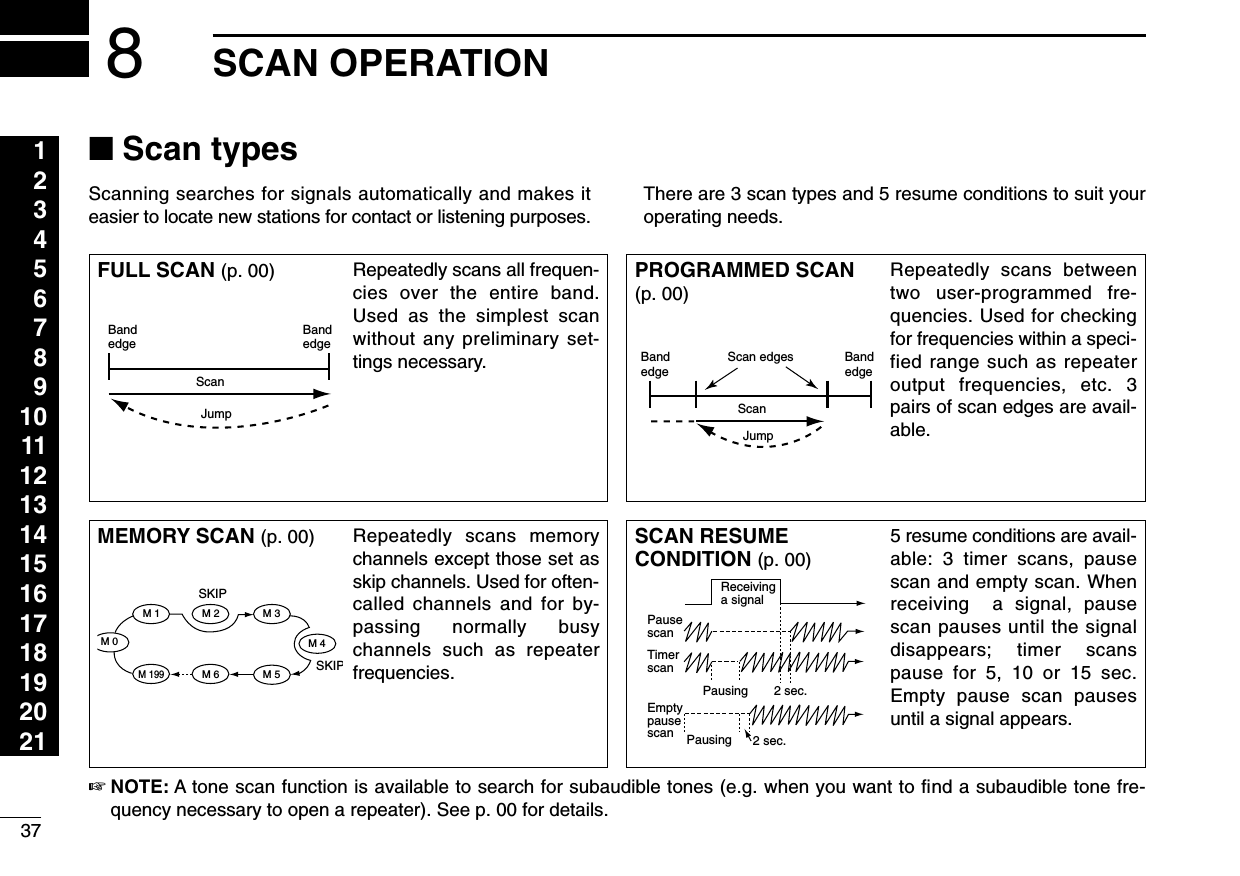
![388SCAN OPERATION123456789101112131415161718192021■Scan start/stopDPreparationScan resume condition (p. 00); program the scan edges(p. 00); program 2 or more memory channels (p. 00); set skipsettings, if desired (p. 00)DOperationqSelect VFO mode for full/programmed scan with[V/MHz(SCAN)]; or memory mode for memory scan with[M/CALL(PRIO)].wSet the squelch to the point where noise is just muted.ePush [V/MHz(SCAN)] for 1 sec. to start the scan.•To change the scanning direction, rotate the tuning dial.•The memory channel readout blinks the scan type as follows:rPush [SET(LOCK)] to switch full and programmed scan.tTo stop the scan, push [V/MHz(SCAN)].zPush [VFO/LOCK] to select VFO mode forfull/programmed scan; push [MR/CALL] to selectmemory mode for memory scan.xSet the squelch to the point where noise is justmuted.cPush [SCAN2(T-SCAN)] to start the scan.•Push [Y] or [Z] for 1 sec. also starts the scan.vPush [SETB(D-OFF)] to switch full and pro-grammed scan.bTo stop the scan push [SCAN2(T-SCAN)] or[CLRA(MW)].SCAN2SETBDuring full scanDuring programmed scanDuring memory scanIndicates scan edge channels.• P1 stands for 1A/1b• P1 to P3 are available when they are programmed.Push [SET(LOCK)] to select full or programmed scan insequence.](https://usermanual.wiki/ICOM-orporated/IC-V8000/User-Guide-201766-Page-41.png)
![398SCAN OPERATION■Scan edges programmingScan edges can be programmed in the same manner asmemory channels. Scan edges are programmed into scanedges, 1A/1b to 3A/3b, in memory channels.qSet the edge frequency of the desired frequency range inVFO mode:➥Set the frequency using the tuning dial.➥Set other data (e.g. repeater settings, etc.) if desired.wPush [MW(S.MW)] momentarily.•“M” indicator and channel number blink.eRotate the tuning dial to select one of scan edge channel,1A, 2A or 3A.rPush [MW(S.MW)] for 1 sec. to program.•3 beeps sound and the frequency is programmed.•Scan edge 1b, 2b or 3b is automatically selected when continu-ing to push [MW(S.MW)] after programming.tTo program a frequency for the other pair of scan edges,1b, 2b or 3b, repeat steps eand r.•If the same frequency is programmed into a pair of scan edges,programmed scan will not function.[EXAMPLE]: Programming 145.300 MHz and 145.800 MHz into scan edges 1A and 1b, respectively.Push momentarily.Rotate for setting frequency, etc. RotateS.MWMWPush for 1 sec. and continue to pushing ➠S.MWMWBeepBeepBeep“Beep“““““](https://usermanual.wiki/ICOM-orporated/IC-V8000/User-Guide-201766-Page-42.png)
![408SCAN OPERATION123456789101112131415161718192021■Scan edges programming via microphonezSet the desired frequency in VFO mode.➥Push [VFO/LOCK] to select VFO mode.➥Set the frequency via the keypad or [Y]/[Z].xPush [FUNC] then [CLRA(MW)] momentarily.cPush [Y] or [Z] to select scan edge channels,1A, 2A or 3A.vPush [FUNC], then push [CLRA(MW)] for 1 sec.to program.•3 beeps may sound and the VFO contents are pro-grammed.•Memory channel number advances to the next scanedge channel, 1b, 2b or 3b, when continuing to push[CLRA(MW)] after programming.bTo program a frequency for the other scan edge channel,repeat steps zto v.MW[EXAMPLE]: Programming 145.300 MHz and 145.800 MHz into scan edges 1A and 1b, respectively.Push Push Push then momentarily.Push Push then 1 sec. and continue to pushing ➠Beep“BeepBeepBeep“““““](https://usermanual.wiki/ICOM-orporated/IC-V8000/User-Guide-201766-Page-43.png)
![418SCAN OPERATION■Skip channel settingThe memory skip function speeds up scanning by checkingonly those memory channels not set as skip channels. Setskip channels as follows.qSelect a memory channel:➥Push [M/CALL(PRIO)] to select memory mode.➥Rotate the tuning dial to select the desired channel tobe a skip channel.wPush [SET(LOCK)] to enter set mode.ePush [SET(LOCK)] or [MW(S.MW)] several times until“CHS” appears as shown above.rRotate the tuning dial to turn the skip function ON or OFFfor the selected channel.•“~” appears : The channel is skipped during scan. (CHS-ON)•“~” disappears : The channel is scanned during scan.(CHS-OFF)tPush [V/MHz(SCAN)] to exit set mode.zSelect a memory channel.➥Select memory mode by pushing [MR/CALL].➥Push [Y] or [Z] to select the desired channelto be a skip channel.xPush [SETB(D-OFF)] to enter set mode.cPush [SETB(D-OFF)] or [ENTC(T-OFF)] severaltimes until “CHS” appears as shown at left.vPush [Y] or [Z] to set or cancel the skip setting.•See item rat left for skip indicator details.bPush [CLRA(MW)] to exit set mode.☞NOTES:Even through scan edge channels cannot be set as skipchannels, the ARE skipped during memory scan.SET mode cannot be accessed when memory names aredisplayed. To set the scan resume condition, return tochannel number indication by pushing [MONI(ANM)] onthe front panel for 1 sec., or push [FUNC] then[MONI1(ANM)] to cancel the channel name indication, thenset as describes above.SETBThe display shows that memory channel 1 is set as a skip channel.USINGSET MODE](https://usermanual.wiki/ICOM-orporated/IC-V8000/User-Guide-201766-Page-44.png)
![428SCAN OPERATION123456789101112131415161718192021■Scan resume conditionThe scan resume condition can be selected as timer, pauseor empty pause scan. The empty pause scan is useful forfinding unused channels. The selected resume condition isalso used for priority watch. (p. 00)qPush [SET(LOCK)] to enter set mode.wPush [SET(LOCK)] or [MW(S.MW)] several times until“SCT” or “SCP” appears as shown above.•Cancel the DTMF memory encoder in advance, if necessary.(p. 00)eRotate the tuning dial to set the desired timer:•“SCT-15”: Scan pauses 15 sec. while receiving a signal.•“SCT-10”: Scan pauses 10 sec. while receiving a signal.•“SCT-5”: Scan pauses 5 sec. while receiving a signal.•“SCP-2”: Scan pauses until the signal disappears and thenresumes 2 sec. later.rPush [V/MHz(SCAN)] to exit set mode.zPush [SETB(D-OFF)] to enter set mode.xPush [SETB(D-OFF)] or [ENTC(T-OFF)] severaltimes until “SCT” or “SCP” appears as shown atleft.•Cancel the DTMF memory encoder in advance, ifnecessary. (p. 00)cPush [Y] or [Z] to select the scan resume condi-tion.•See item eat left for scan resume condition details.vPush [CLRA(MW)] to exit set mode.☞NOTE: SET mode cannot be accessed when memory names aredisplayed. To set the scan resume condition, return tochannel number indication by pushing [MONI(ANM)] onthe front panel for 1 sec., or push [FUNC] then[MONI1(ANM)] to cancel the channel name indication, thenset as describes above.SETBThe display shows that the scan will resume 15 sec. after it stops.USINGSET MODE](https://usermanual.wiki/ICOM-orporated/IC-V8000/User-Guide-201766-Page-45.png)
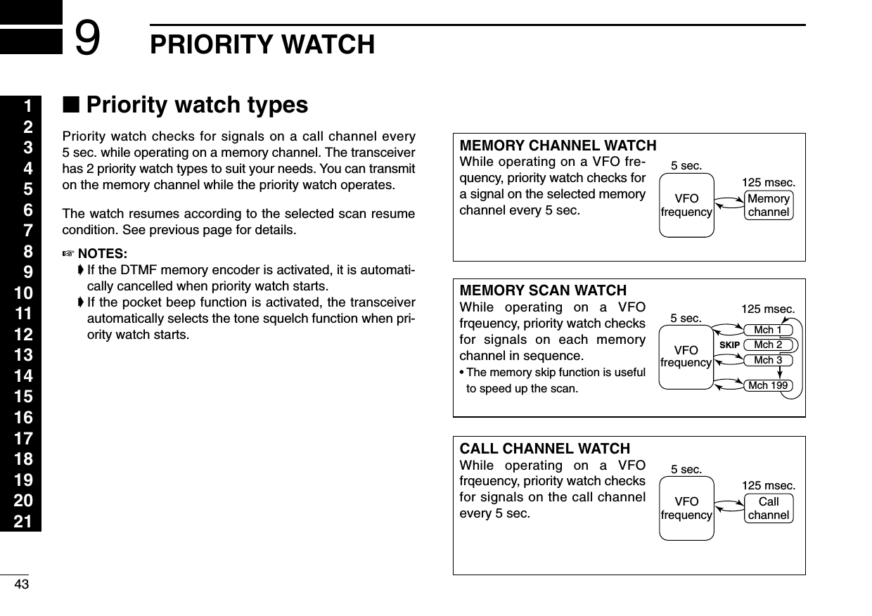
![449PRIORITY WATCH123456789101112131415161718192021■Priority watch operationqSelect memory mode; then, set an operating frequency.wSet the watching channel(s).For memory channel watch:Select the desired memory channel.For memory scan watch:Select memory mode; then, push [V/MHz(SCAN)] for1 sec. to start memory scan.For call channel watch:Select the call channel by pushing [M/CALL(PRIO)] onceor twice.ePush [M/CALL(PRIO)] for 1 sec. to start the watch.•The transceiver checks the memory or call channel every 5 sec.•The watch resumes according to the selected scan resume con-dition. (p. 00)•While the watch is pausing, pushing [M/CALL(PRIO)] resumesthe watch manually.rPush [M/CALL(PRIO)] while the display shows the mem-ory channel to stop the watch.zSelect memory mode; then, set an operating fre-quency.xSet the watching channel(s).For memory channel watch:Push [MR/CALL] then [Y] or [Z] to select the de-sired call channel.For memory scan watch:Push [MR/CALL], then push [SCAN2] to start thememory scan.For call channel watch:Push [MR/CALL] for 1 sec. to select the callchannel.cPush [PRIO3(PTT-M)] to start the watch.•The transceiver checks the memory or call channelevery 5 sec.•The watch resumes according to the selected scan re-sume condition. (p. 00)•To resume the watch manually when paused, push[PRIO3(PTT-M)] or [CLRA(MW)].vTo stop the watch, push [CLRA(MW)] once (ortwice while watch is paused).PRIO3While pausing or receiving a signal on the memory or call chanel, “PRIO” blinks.](https://usermanual.wiki/ICOM-orporated/IC-V8000/User-Guide-201766-Page-47.png)
![45DTMF MEMORY ENCODER12345678910111213141516171819202110■Programming a DTMF codeDTMF codes are used for autopatching, controlling otherequipment, etc. The transceiver has 10 DTMF memory chan-nels (d0–d9) for storage of often-used DTMF codes of up to24 digits.zPush [FUNC] then [LOW6(DTCS)] to turn theDTMF encoder ON.•“d” appears in place of the 100 MHz digit.xPush [SETB(D-OFF)] to enter the DTMF mem-ory programming condition.cPush [Y] or [Z] to select the desired DTMFmemory channel.vPush the desired digit keys.•When the first digit is input, previous memory contents arecleared automatically.•“E” stands for “M” and “F” stands for “# .”•Push [Y]/[Z] and repeat this step if you make a mistake.•The S/RF indicator shows the digit group. The indication in-creases every 6 digits.bPush [VFO/LOCK] to exit the programming condition.•The [CLRA(MW)] key cannot be used to exit. If pushed, code “A”is input and the previously programmed data is erased. Repro-gram in such a case.DTMF[EXAMPLE]: Programming “5428AB453” into DTMF memory channel “d4.”PushPush PushPushPush then .](https://usermanual.wiki/ICOM-orporated/IC-V8000/User-Guide-201766-Page-48.png)
![4610DTMF MEMORY ENCODER123456789101112131415161718192021■Transmitting a DTMF codeDAutomatic transmission (DTMF memory)zPush [FUNC] then [LOW6(DTMF)] to turn theDTMF encoder ON.•“d” appears in place of the 100 MHz digit.xPush [SETB(D-OFF)] to enter the DTMF mem-ory programming condition.cPush [Y] or [Z] to select the desired channel.vPush [PTT] to transmit the selected memory.•Exit the programming condition automatically.•Each push of [PTT] transmits the DTMF code.bPush [FUNC] then [SETB(D-OFF)] to cancel theDTMF encoder.•When the DTMF encoder is turned ON continuously,each push of the PTT transmits the previously se-lected DTMF code.DTransmitting a DTMF memory directlyzPush [DTMF-S] to turn the DTMF memory di-rect selection ON.•The function indicator (microhpne) lights green.xPush the desired DTMF channel number.•“0” to “9” are available for channel numbers.•Automatically transmits the selected DTMF code.NOTE: When no DTMF code programmed channelnumber is pushed, transmits for 1 sec. with-out DTMF code.cPush [DTMF-S] again to deactivate the DTMFmeory direct selection.DManual transmissionzPush [DTMF-S] to turn the DTMF memory di-rect selection ON.•The function indicator (microhpne) lights green.xPush one of “A” to “F” key momentarily, thenpush the desired DTMF keys.•A: [CLRA(MW)] B: [SETB(D-OFF)], C: [ENTC(T-OFF)] D: [SQLYD(MUTE)], E: [✱(TONE-1)] F: [SQLZ#(16KEY-L)]•Automatically transmits without pushing PTT.•The first code, one of “A” to “F”, does not transmit-ted. DTMF code transmission started from the 2ndcode.cPush [DTMF-S] again to deactivate the DTMFmeory direct selection.DTMF-SDTMF-SDTMF](https://usermanual.wiki/ICOM-orporated/IC-V8000/User-Guide-201766-Page-49.png)
![4710 DTMF MEMORY ENCODER■DTMF speedThe rate at which DTMF memories send individual DTMFcharacters can be set to accommodate operating needs.qPush [PWR] for 1 sec. to turn power OFF.wWhile pushing [SET(LOCK)], push [PWR] for 1 sec. to turnpower ON and enter initial set mode.ePush [SET(LOCK)] or [MW(S.MW)] several times to selectthe “DTD” display as shown above.rRotate the tuning dial to select the desired speed asshown in the table below.tPush [PWR] to exit initial set mode.cps=characters/secThe display shows the fast-est DTMF speed is select-ed.USINGINITIAL SET MODEDISPLAY INTERVAL SPEEDDTD-- 1 100 msec. 5.0 cpsDTD-- 2 200 msec. 2.5 cpsDTD-- 3 300 msec. 1.6 cpsDTD-- 5 500 msec. 1.0 cps](https://usermanual.wiki/ICOM-orporated/IC-V8000/User-Guide-201766-Page-50.png)
![4811POCKET BEEP AND TONE SQUELCH123456789101112131415161718192021■Pocket beep operationThis function uses subaudible tones for calling and can beused as a “common pager” to inform you that someone hascalled while you were away from the transceiver.DWaiting for a call from a specific stationqSet the operating frequency.wPush [SET(LOCK)] to enter set mode.ePush [SET(LOCK)] or [MW(S.MW)] several times until “Ct”for tone squelch or “dt” for DTCS squelch appears.rRotate the tuning dial to select the desired tone squelchfrequency or DTCS code and porality.tPush [V/MHz(SCAN] to exit set mode.yPush [TONE(T-SCAN)] several times to indicate “” fortone squelch or “D” for DTCS squelch in the functiondisplay.uWhen a signal with the matched tone is received, thetransceiver emits beep tones and flashes “”.•Beep tones sound for 30 sec and “” flashes. To stop the beepsand flashing manually, push any key. When the beep tones arenot stopped manually, “” continues flashing until step i.iPush [PTT] to answer.oPush [TONE(T-SCAN)] several times to cancel the func-tion.zSet the operating frequency.xProgram the CTCSS tone frequency or DTCS code in setmode.•See p. 18 for programming details.cPush [FUNC] then [iT SQLS] to turn the pocket beepON.vWhen a signal with the matched tone is received, thetransceiver emits beep tones for 30 sec. and flashes“S”.bPush [PTT] to answer or push [clr A(MW)] to stop thebeeps and flashing.•Tone squelch is automatically selected.•Pushing [FUNC] then [oTSQL] also selects thetone squelch.nTo cancel the function, push [FUNC] then [GT-OFF].DCalling a waiting station using pocket beepA subaudible tone matched with the station’s CTCSS tone fre-quency or 3-digit DTCS code with polarity is necessary. Usethe tone squelch on the next page or a subaudible tone en-coder (pgs. 00, 00)■Tone squelch operationThe tone squelch opens only when receiving a signal with thesame pre-programmed subaudible tone.Tone squelch frqueency setting DTCS code setting](https://usermanual.wiki/ICOM-orporated/IC-V8000/User-Guide-201766-Page-51.png)
![4911 POCKET BEEP AND TONE SQUELCHqSet the operating frequency.wProgram the CTCSS tone frequency or DTCS code in setmode.•See p. 18 for programming details.ePush [TONE(T-SCAN)] several times. “T SQL” appears inthe function display.rWhen a signal with the matched tone is received, thesquelch opens and the signal can be heard.•When the received signal includes an unmatched tone, thesquelch does not open. However, the S/RF indicator shows thereceived signal strength.•To open the squelch manually, push [MONI(ANM)].tOperate the transceiver in the normal way (push [PTT] totransmit; release [PTT] to receive).yTo cancel the tone squelch, push [TONE(T-SCAN)].•“T SQL” disappears from the function display.zSet the operating frequency.xProgram the CTCSS tone frequency or DTCS code in setmode.•See p. 18 for programming details.cPush [FUNC] then [oT SQL] to turn the tone squelch ON.vWhen a signal with the matched tone is received, thesquelch opens and the signal can be heard.•When the received signal includes an incorrect tone,the squelch does not open. However, the S/RF indi-cator shows the received signal strength.•To open the squelch manually, push [qMONI].bOperate the transceiver in the normal way (push [PTT] totransmit; release [PTT] to receive.nTo cancel the tone squelch, push [FUNC] then [GT-OFF].■Tone scanBy monitoring a signal that is being operated with pocketbeep or tone squelch function, you can determine the tonefrequency necessary to open a squelch.qSet the channel to be checked for a tone frequency.wPush [(TONE)T-SCAN] for 1 sec. to start the tone scan.•To change the scanning direction, rotate the tuning dial.eWhen the CTCSS tone frequency or 3-digit DTCS code ismatched, the squelch opens and the tone frequency istemporarily programmed into the selected mode such asmemory or call channel.•The tone scan pauses when a CTCSS tone frequency or 3-digitDTCS code is detected.•The decoded CTCSS tone frequency or 3-digit DTCS code isused for the tone encoder or tone encoder/decoder dependingon the tone squelch ON/OFF setting.rPush [V/MHz(SCAN)] to stop the scan.zSet the channel to be checked for a tone frequency.xPush [F-2] for 1 sec. to start the tone scan.cWhen the tone frequency is matched, the squelch opensand the tone frequency is programmed into the selectedmode such as memory or call channel.vPush [clr A(MW)] to stop the scan.☞NOTE: The decoded tone frequency is programmed tem-porarily when a memory or call channel is selected. How-ever, this will be cleared when overwriting the memory/callchannel.](https://usermanual.wiki/ICOM-orporated/IC-V8000/User-Guide-201766-Page-52.png)