ICOM orporated IC-V8000 Amateur Scanning Transceiver User Manual Manual
ICOM Incorporated Amateur Scanning Transceiver Manual
Manual

INSTRUCTION MANUAL
iV8000
VHF FM TRANSCEIVER
This device complies with Part 15 of the FCC rules. Operation is sub-
ject to the following two conditions: (1) This device may not cause
harmful interference, and (2) this device must accept any interference
received, including interference that may cause undesired operation.
FOREWORD
Thank you for purchasing this Icom product. The IC-V8000
VHF FM TRANSCEIVER
is designed and built with Icom’s supe-
rior technology and craftsmanship. With proper care, this prod-
uct should provide you with years of trouble-free operation.
We understand making you have a choice of many different
radios in the market place. I want to take a couple of mo-
ments of your time to thank you for making your IC-V8000
your radio of choice, and hope you agree with ICOM’s philos-
ophy of “technology first.” Many hours of research and devel-
opment went into the design of your IC-V8000.
FEATURES
❍75 W* of high transmit output power
(except Taiwan version)
❍Front mounted speaker for clear readability
❍Tone squelch, DTCS squelch standard
❍Dual color (amber & green) LCD backlight
❍Remote control microphone available
(optional for some versions)
❍Optional DTMF decoder
IMPORTANT
READ ALL INSTRUCTIONS carefully and completely
before using the transceiver.
SAVE THIS INSTRUCTION MANUAL— This in-
struction manual contains important operating instructions for
the IC-V8000.
EXPLICIT DEFINITIONS
i
WORD DEFINITION
RWARNING!
CAUTION
NOTE
Personal injury, fire hazard or electric shock
may occur.
Equipment damage may occur.
Recommended for optimum use. No risk of
personal injury, fire or electric shock.
Icom, Icom Inc. and the are registered trademarks of Icom In-
corporated (Japan) in the United States, the United Kingdom, Ger-
many, France, Spain, Russia and/or other countries.

ii
CAUTIONS
RWARNING RF EXPOSURE! This device emits
Radio Frequency (RF) energy. Extreme caution should be ob-
served when operating this device. If you have any questions re-
garding RF exposure and safety standards please refer to the
Federal Communications Commission Office of Engineering and
Technology’s report on Evaluating Compliance with FCC Guide-
lines for Human Radio frequency Electromagnetic Fields (OET
Bulletin 65)
RWARNING! NEVER connect the transceiver to an AC
outlet. This may pose a fire hazard or result in an electric shock.
RWARNING! NEVER operate the transceiver while dri-
ving a vehicle. Safe driving requires your full attention—anything
less may result in an accident.
NEVER connect the transceiver to a power source of more
than 16 V DC. This will ruin the transceiver.
NEVER connect the transceiver to a power source using re-
verse polarity. This will ruin the transceiver.
NEVER cut the DC power cable between the DC plug and
fuse holder. If an incorrect connection is made after cutting, the
transceiver may be damaged.
NEVER place the transceiver where normal operation of the
vehicle may be hindered or where it could cause bodily injury.
NEVER let objects impede the operation of the cooling fan on
the rear panel.
DO NOT push the PTT when not actually desiring to trans-
mit.
DO NOT allow children to play with any radio equipment con-
taining a transmitter.
During mobile operation, DO NOT operate the transceiver
without running the vehicle’s engine. When the transceiver’s
power is ON and your vehicle’s engine is OFF, the vehicle’s bat-
tery will soon become exhausted.
BE CAREFUL! The transceiver will become hot when op-
erating it continuously for long periods.
AVOID using or placing the transceiver in direct sunlight or in
areas with temperatures below –10°C (+14˚F) or above +60°C
(+140˚F).
AVOID the use of chemical agents such as benzine or alcohol
when cleaning, as they can damage the transceiver’s surfaces.
USE Icom microphones only (supplied or optional). Other man-
ufacturer’s microphones have different pin assignments and may
damage the transceiver if attached.
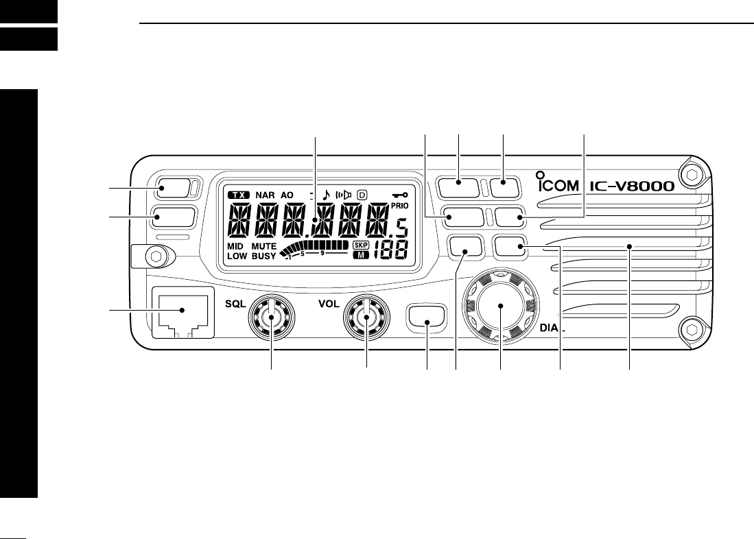
■Front panel
qPOWER SWITCH [PWR]
Turns power ON and OFF when pushed for 1 sec.
wMEMORY/CALL•PRIORITY SWITCH [M/CALL(PRIO)]
(p. 00)
➥Push to selects and toggles memory, call and weather
channel* mode.
*Weather channels available for USA versions only.
➥Starts priority scan when pushed for 1 sec.
eMICROPHONE CONNECTOR
Connects the supplied microphone. (p. 00)
rSQUELCH CONTROL [SQL]
Varies the squelch level. (p. 00)
• The RF attenuator activates and increases the attenuation when
rotated clockwise to the center position and further.
tVOLUME CONTROL [VOL]
Adjusts the audio level. (p. 00)
OPT
BANK
V/MHz
SCAN
LOW
DUP
MONI
ANM
SET
LOCK
PWR
S.MW
MW
T-SCAN
TONE
PRIO
M/CALL
t
Function display (p. 00)
q
w
e
ryuioSpeaker
!0!1!2!3
1
PANEL DESCRIPTION
1
2
3
4
5
6
7
8
9
10
11
12
13
14
15
16
17
18
19
20
21
1

2
1
PANEL DESCRIPTION
1
2
3
4
5
6
7
8
9
10
11
12
13
14
15
16
17
18
19
20
21
yBANK•OPTION SWITCH [BANK(OPT)]
➥Selects memory memory bank when pushed. (p. 00)
➥Push for 1 sec. to turn the DTMF decoder ON and OFF
when the optional UT-108 is installed. (p. 00)
uSET•LOCK SWITCH [SET(LOCK)]
➥Selects set mode when pushed.
➥Switches the lock function ON and OFF when pushed
for 1 sec. (p. 14)
iTUNING DIAL [DIAL]
Selects the memory channel (p. 00), call channel (pgs. 00,
00, 00), the contents of the set mode display and the
scanning direction (p. 00).
oMEMORY WRITE SWITCH [MW(S.MW)]
➥Enter to memory edit mode when pushed. (p. 00)
➥Program into the selected memory channel when
pushed for 1 sec. (p. 00)
•Continue to hold the switch to increment the memory channel
automatically.
!0 MONITOR•CHANNEL NAME SWITCH [MONI(ANM)]
➥Push to switch the monitor function ON and OFF. (p. 00)
➥Push for 1 sec. to toggle the frequency indication and
channel name indication. (p. 00)
!1 OUTPUT POWER SWITCH [LOW(DUP)]
➥Each push changes the output power selection. (p. 00)
➥Select DUP–, DUP+ and simplex operation when
pushed for 1 sec. (p. 00)
!2 TONE/TONE SCAN SWITCH [TONE(T-SCAN)]
➥Each push selects a tone function. (p. 00)
•Tone encoder, pocket beep, tone squelch or tone function
OFF can be selected.
➥Push for 1 sec. to start/stop the tone scan function.
(p. 00)
!3 VFO/MHz TUNING•SCAN SWITCH [V/MHz(SCAN)]
➥Selects and toggles VFO mode and 1 MHz or 100 kHz
tuning when pushed. (p. 00)
•Cancels a scan when pushed during scan.
➥Starts scan when pushed for 1 sec. (p. 00)
DMicrophone connector (front panel view)
q+8 V DC output (Max. 10 mA)
wChannel up/down
e8 V control IN
rPTT
tGND (microphone ground)
yMIC (microphone input)
uGND
iData IN
qi
3
1PANEL DESCRIPTION
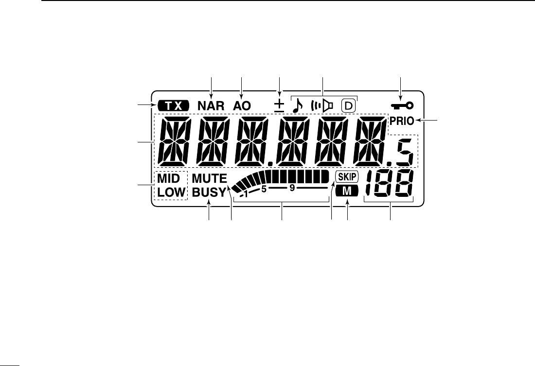
■Function display
qTRANSMIT INDICATOR
➥Appears while transmitting. (p. 00)
➥Flashes while transmitting with the one-touch PTT func-
tion. (p. 00)
wFREQUENCY READOUT
Shows the operating frequency, channel names, set mode
contents, etc.
•Frequency decimal point flashes while scanning. (p. 00)
•“d” appears in place of the 1st digit while the DTMF memory
function is in use. (p. 00)
eOUTPUT POWER INDICATORS (p. 00)
“LOW” appears when low output power; “LOW” and “MID”
appear when low mid output power; “MID” appears when
middle output power is selected
rBUSY INDICATOR
➥Appears when a signal is being received or the squelch
is open. (p. 00)
➥Flashes while the monitor function is activated. (p. 00)
tAUDIO MUTE INDICATOR (p. 00)
Appears when the audio mute function is activated via mi-
crophone control.
t
q
w
e
ryuio
!3!4!5
!0
!1!2

4
1
PANEL DESCRIPTION
1
2
3
4
5
6
7
8
9
10
11
12
13
14
15
16
17
18
19
20
21
yS/RF INDICATORS
➥Show the relative signal strength while receiving sig-
nals. (p. 00)
➥Show the output power level while transmitting. (p. 00)
uSKIP INDICATOR (p. 00)
Appears when the displayed memory channel is specified
as a skip channel.
iMEMORY INDICATOR (p. 00)
Appears when memory mode is selected.
oMEMORY CHANNEL NUMBER INDICATORS
➥Shows the selected memory channel number. (p. 00)
➥“C” appears when the call channel is selected. (p. 00)
!0PRIORITY WATCH INDICATOR (p. 00)
Appears while the priority watch is activated; flashes while
the watch is paused.
!1LOCK INDICATOR (p. 00)
Appears when the lock function is activated.
!2TONE INDICATORS
➥“” appears while the subaudible tone encoder is in
use. (p. 00)
➥“” appears while the tone (CTCSS) squelch function is
in use. (p. 00)
➥“D” appears while the tone (DTCS) squelch function is in
use. (p. 00)
➥“” appears with the “” or “D” indicator while the
pocket beep function (CTCSS or DTCS) is in use. (p. 00)
!3DUPLEX INDICATORS (p. 00)
“+” appears when positive duplex, “–” appears when neg-
ative duplex operation is selected.
!4AUTO POWER-OFF INDICATOR (p. 00)
Appears while the auto power-off function is in use.
!5NARROW MODE INDICATOR (p. 00)
Appears when the narrow mode is selected.
*The narrow mode is available with some version
5
1PANEL DESCRIPTION
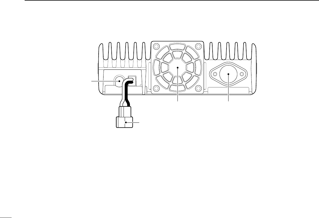
■Rear panel
qSPEAKER JACK [SP]
Accepts an 8 Ωspeaker.
•Audio output power is more than 2.0 W.
wPOWER RECEPTACLE [DC13.8V]
Accepts 13.8 V DC ±15% with the supplied DC power
cable.
☞NOTE: DO NOT use a cigarette lighter socket as a
power source when operating in a vehicle. The plug
may cause voltage drops and ignition noise may be su-
perimposed onto transmit or receive audio.
eCOOLING FAN
rANTENNA CONNECTOR [ANT]
Connects a 50 Ωantenna with a PL-259 connector and a
50 Ωcoaxial cable.
q
w
er
6
1
PANEL DESCRIPTION
1
2
3
4
5
6
7
8
9
10
11
12
13
14
15
16
17
18
19
20
21
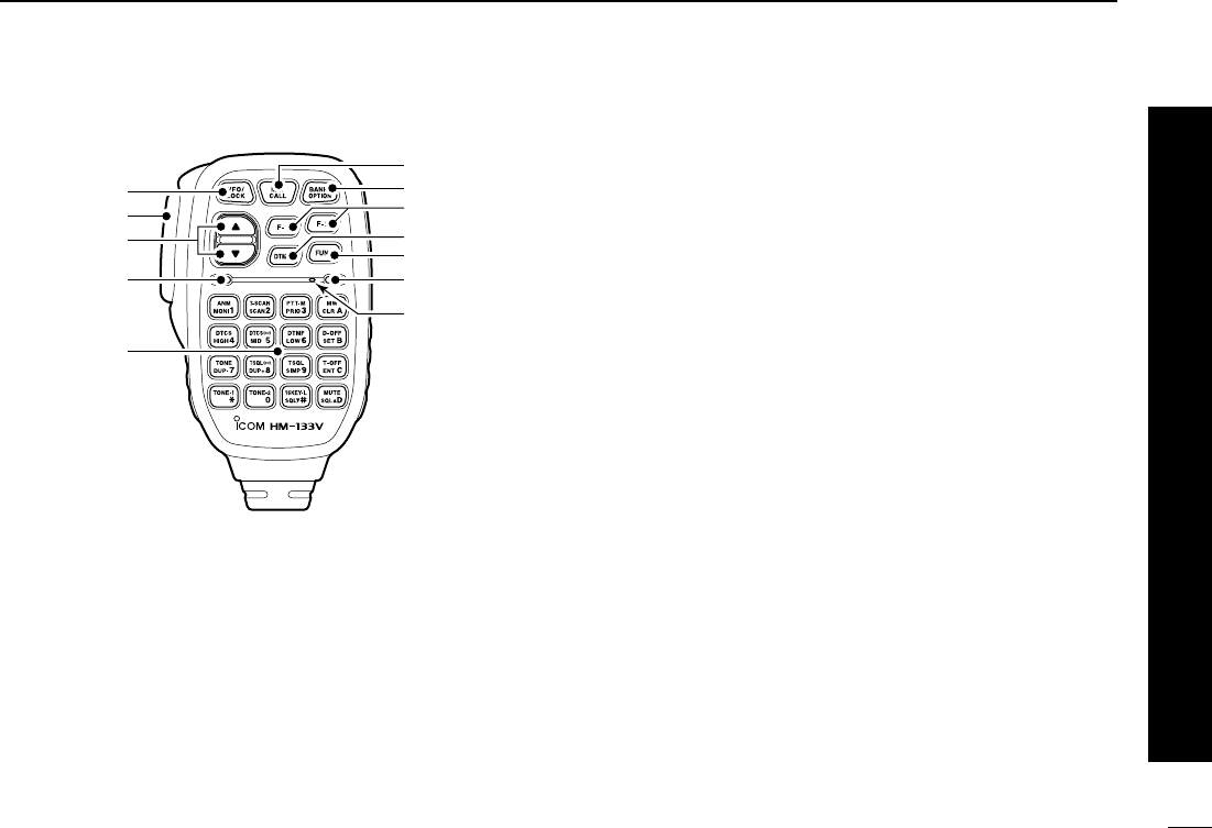
■Microphone (HM-133V*)
qVFO/LOCK SWITCH [VFO/LOCK]
➥Push to select VFO mode. (p. 00)
➥Push for 1 sec. to switch the lock function ON and OFF.
(p. 00)
wPTT SWITCH
➥Push and hold to transmit; release to receive.
➥Switches between transmitting and receiving while the
one-touch PTT function is in use. (p. 00)
eUP/DOWN SWITCHES [Y]/[Z]
➥Push either switch to change memory channel, call
channel, set mode contents, etc. (pgs. 00, 00)
➥Push either switch for 1 sec. to start scanning. (p. 00)
rACTIVITY INDICATOR
➥Lights red while any key, except [FUNC] and [DTMF-S],
is pushed, or while transmitting.
➥Lights green while the one-touch PTT function is in use.
tKEYPAD (p. 00)
yFUNCTION INDICATOR
➥Lights orange while [FUNC] is activated—indicates the
secondary function of switches can be accessed.
➥Lights green when [DTMF-S] is activated—DTMF sig-
nals can be transmitted with the keypad.
uFUNCTION SWITCH [FUNC] (p. 00)
iDTMF MEMORY SELECT SWITCH [DTMF-S] (p. 00)
oFUNCTION SWITCHES [F-1]/[F-2] (p. 00)
Assign your desired key function from the front panel
switches.
•Default settings are [LOW(DUP)] for [F-1] and [TONE(T-SCAN)]
for [F-2] ([T-SCAN] when pushed and held).
!2BANK/OPTION SWITCH [BANK/OPTION]
➥Push to select memory bank. (p. 00)
➥Push for 1 sec. to activate the installed optional unit.
(p. 00)
yMEMORY/CALL SWITCH [MR/CALL]
➥Push to select memory mode. (p. 00)
➥Push for 1 sec. to select call channel. (p. 00)
q
e
r
t
Mic element
y
u
i
o
!0
!1
w
*
A different microphone
may be supplied de-
pending on version.
7
1PANEL DESCRIPTION
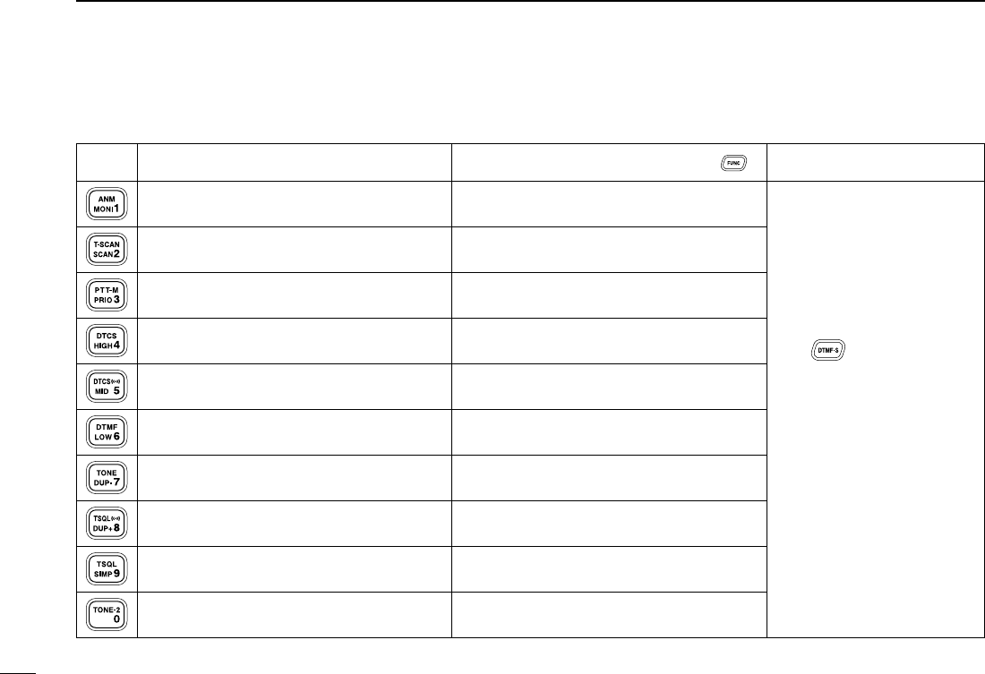
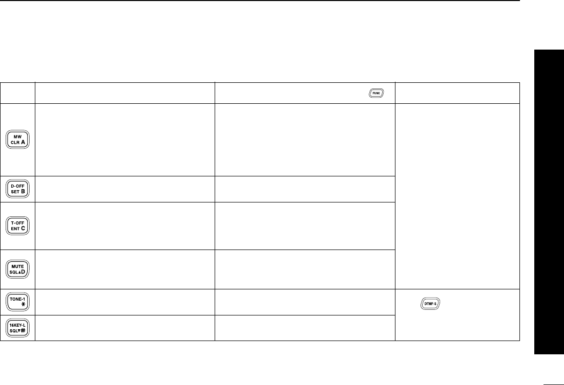
■Microphone keypad
KEY FUNCTION
SECONDARY FUNCTION (after )
OTHER FUNCTIONS
Switches between opening and closing the
squelch.
Starts and stops scanning. (p. 00)
Starts and stops priority watch. (p. 00)
Selects high output power. (p. 00)
Selects mid. output power. (p. 00)
Selects low output power (p. 00)
Selects minus duplex operation. (p. 00)
Selects plus duplex operation. (p. 00)
Selects simplex operation. (p. 00)
No primary function.
Switches between frequency indication and
memory names indication. (p. 00)
Starts and stops tone scanning. (p. 00)
Turns the one-touch PTT function ON and
OFF. (p. 00)
Turns the DTCS squelch ON. (p. 00)
Turns the DTCS pocket beep function ON.
(p. 00)
Turns the DTMF memory encoder function
ON. (p. 00)
Turns the subaudible tone encoder ON.
(p. 00)
Turns the CTCSS pocket beep function
ON. (p. 00)
Turns the tone squelch function ON.
(p. 00)
Sends a 1750 Hz tone signal while pushing
and holding. (p. 00)
After :
Transmit the appropriate
DTMF code or push [0] to [9],
[A] to [D] to transmit the
DTMF memory contents
when the DTMF memory en-
coder is activated. (p. 00)
8
1
PANEL DESCRIPTION
1
2
3
4
5
6
7
8
9
10
11
12
13
14
15
16
17
18
19
20
21
➥Clears a digit before entry. (p. 00)
➥Cancels the scan, priority watch or
DTMF memory function. (pgs. 00, 00)
➥Exit set mode (p. 00)
➥Increases the set mode selection order
after entering set mode. (p. 00)
Enters set mode and advances the set
mode selection.
➥Sets the keypad for numeral input
(p. 00)
➥
Decreases the set mode selection order
after entering set mode.
Adjusts the squelch level increments.
(p. 00)
No primary function.
Adjusts the squelch level decrement.
➥Writes memory contents into the call
channel. (p. 00)
➥Advances the memory channel number
when continuously pushed after pro-
gramming is completed. (p. 00)
DTMF memory OFF.
Turns the subaudible tone encoder, pocket
beep or CTCSS/DTCS tone squelch OFF.
(pgs. 00, 00, 00)
Mutes the audio. (p. 00)
•Mute function is released when any operation
is performed.
Locks the digit keys on the keypad (includ-
ing the A to D, # and Mkeys. (p. 14)
Sends a 1750 Hz tone signal for 0.5 sec.
(p. 00)
After :
Transmits the appropriate
DTMF code. (p. 00)
[A] to [D] transmit DTMF
memories. (p. 00)
KEY FUNCTION
SECONDARY FUNCTION (after )
OTHER FUNCTIONS
9
INSTALLATION
1
2
3
4
5
6
7
8
9
10
11
12
13
14
15
16
17
18
19
20
21
2
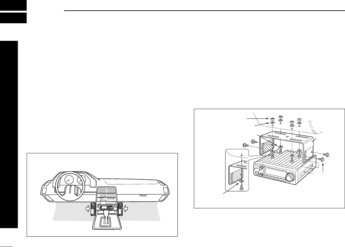
■Location
Select a location which can support the weight of the trans-
ceiver and does not interfere with driving in any way. We rec-
ommend the locations shown in the diagram below.
NEVER place the transceiver where normal operation of the
vehicle may be hindered or where it could cause bodily injury.
NEVER place the transceiver where air bag deployment may
be obstructed.
DO NOT place the transceiver where hot or cold air blows di-
rectly onto it.
AVOID placing the transceiver in direct sunlight.
■Using the mounting bracket
➀Drill 4 holes where the mounting bracket is to be installed.
•Approx. 5.5–6 mm (3⁄16″) when using nuts; approx. 2–3 mm (1⁄16″)
when using self-tapping screws.
➁Insert the supplied screws, nuts and washers through the
mounting bracket and tighten.
➂Adjust the angle for the clearest view of the function dis-
play.
Nut
Spring washer
Flat washer
When using
self-tapping
screws
Spring
washer
Mounting
nut
Mounting
bracket
• Example— Installation location
Draft Only
10
2
INSTALLATION
1
2
3
4
5
6
7
8
9
10
11
12
13
14
15
16
17
18
19
20
21
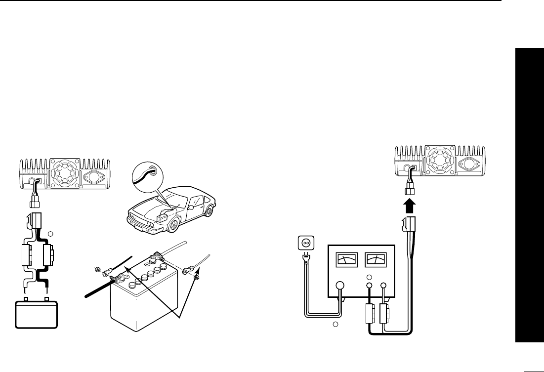
■Battery connection
☞NEVER connect the transceiver directly to a 24 V battery.
☞DO NOT use the cigarette lighter socket for power con-
nections.
Attach a rubber grommet when passing the DC power cable
through a metal plate to prevent short circuits.
•CONNECTING TO A DC POWER SOURCE
•See p. 00 for fuse replacement.
■DC power supply connection
Use a 13.8 V DC power supply with more than 12 A capacity.
Make sure the ground terminal of the DC power supply is
grounded.
•CONNECTING TO A DC POWER SUPPLY
•See p. 00 for fuse replacement.
DC power
supply 13.8 V
to an
AC
outlet
Fuses
20 A
black
red⊕
−
⊕
−
Fuses
20 A
black
red⊕
Grommet
−
12 V
12 V
battery
Supplied
DC power cable
+ red
_ black
11
2INSTALLATION
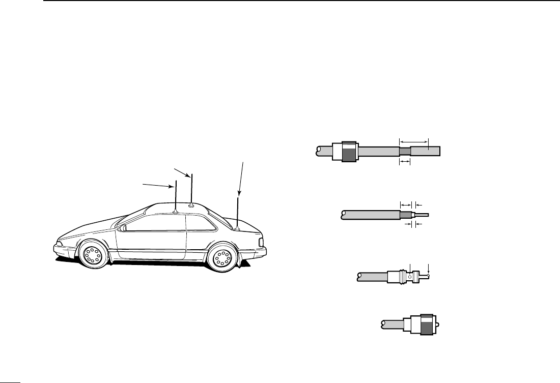
■Antenna installation
DAntenna location
To obtain maximum performance from the transceiver, select
a high-quality antenna and mount it in a good location. A non-
radial antenna should be used when using a magnetic mount.
DAntenna connector
The antenna uses a PL-259 connector.
•PL-259 CONNECTOR
qSlide the coupling ring
down. Strip the cable
jacket and soft solder.
wStrip the cable as shown
at right. Soft solder the
center conductor.
eSlide the connector
body on and solder it.
rScrew the coupling ring
onto the connector body.
(10 mm ≈3⁄8 in)
30 mm
10 mm (soft solder)
10 mm
1–2 mm
solder solder
Soft
solder
Coupling ring
Roof-mount antenna
(Drill a hole or use a magnetic mount.)
Gutter-mount antenna
Trunk-mount
antenna
12
3
SETTING A FREQUENCY
1
2
3
4
5
6
7
8
9
10
11
12
13
14
15
16
17
18
19
20
21
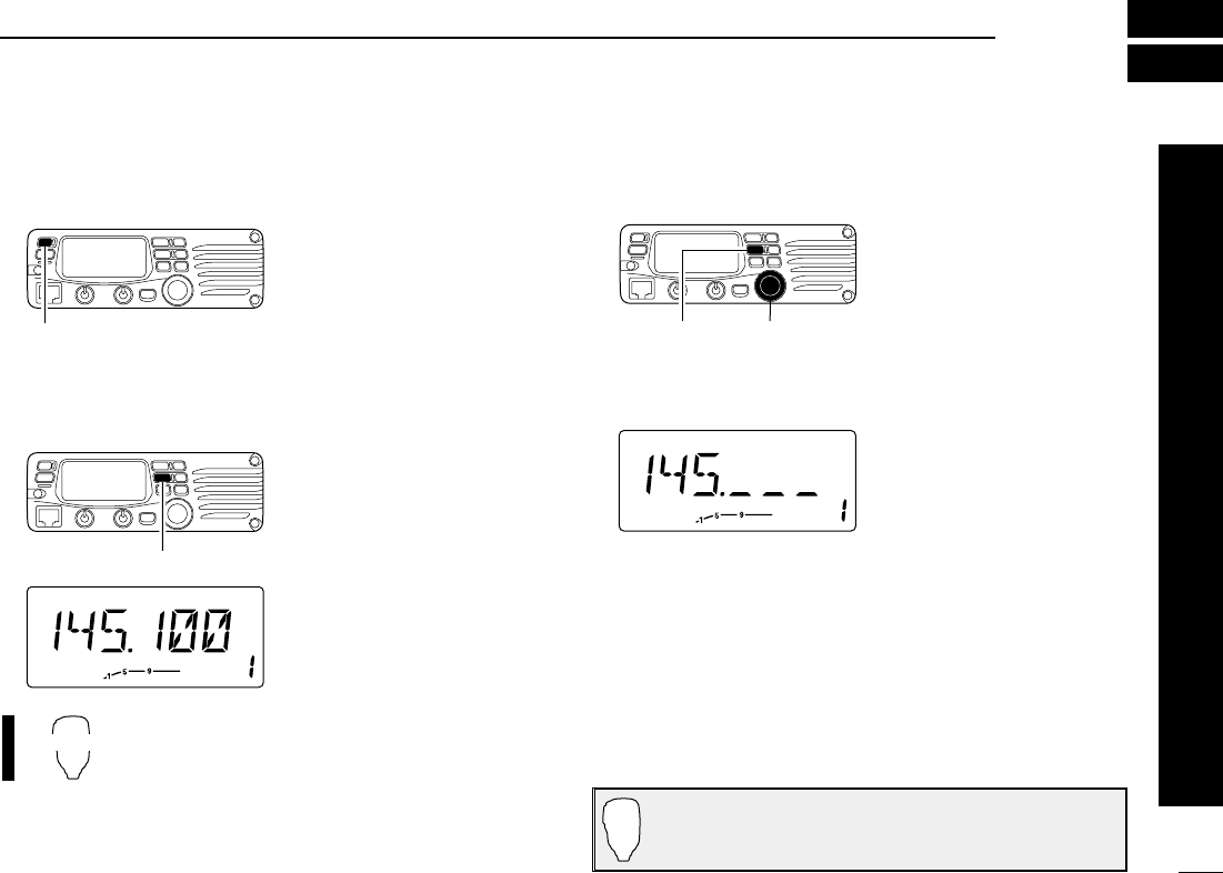
■Preparation
DTurning power ON/OFF
➥Push [PWR] for 1 sec. to
turn power ON or OFF.
DVFO mode selection
The transceiver has 2 basic operating modes: VFO mode and
memory mode.
➥Push [V/MHz(SCAN)] to
select VFO mode.
➥Push [VFO/LOCK] to select VFO mode.
■Using the tuning dial
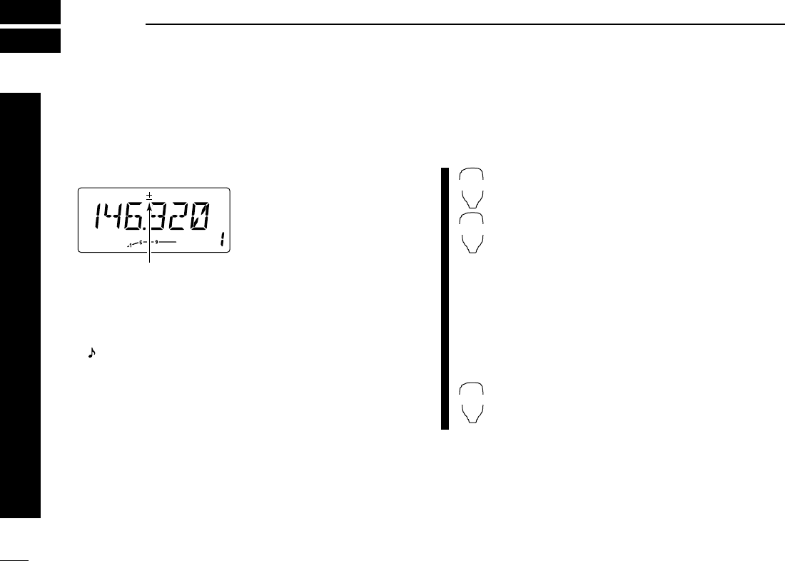
qRotate the tuning dial to set the frequency.
•If VFO mode is not selected,
push [V/MHz(SCAN)] to select
VFO mode.
•The frequency changes ac-
cording to the selected tuning
steps. (p. 00)
wTo change the frequency in 1 MHz (10 MHz for some ver-
sions) steps, push [V/MHz(SCAN)], then rotate the tuning
dial.
•Pushing [V/MHz(SCAM)] for
1 sec. starts scan function. If
scan starts, push
[V/MHz(SCAN)] again to can-
cel it.
The display shows that the
1 MHz tuning step is selected.
Tunig dial[V/MHz(SCAN)]
VFO/LOCK
Push [V/MHz(SCAN)]
Push [PWR] for 1sec.
Note that in this manual, sections beginning with a micro-
phone icon (as above), designate operation via the HM-
133V microphone.
13
3SETTING A FREQUENCY
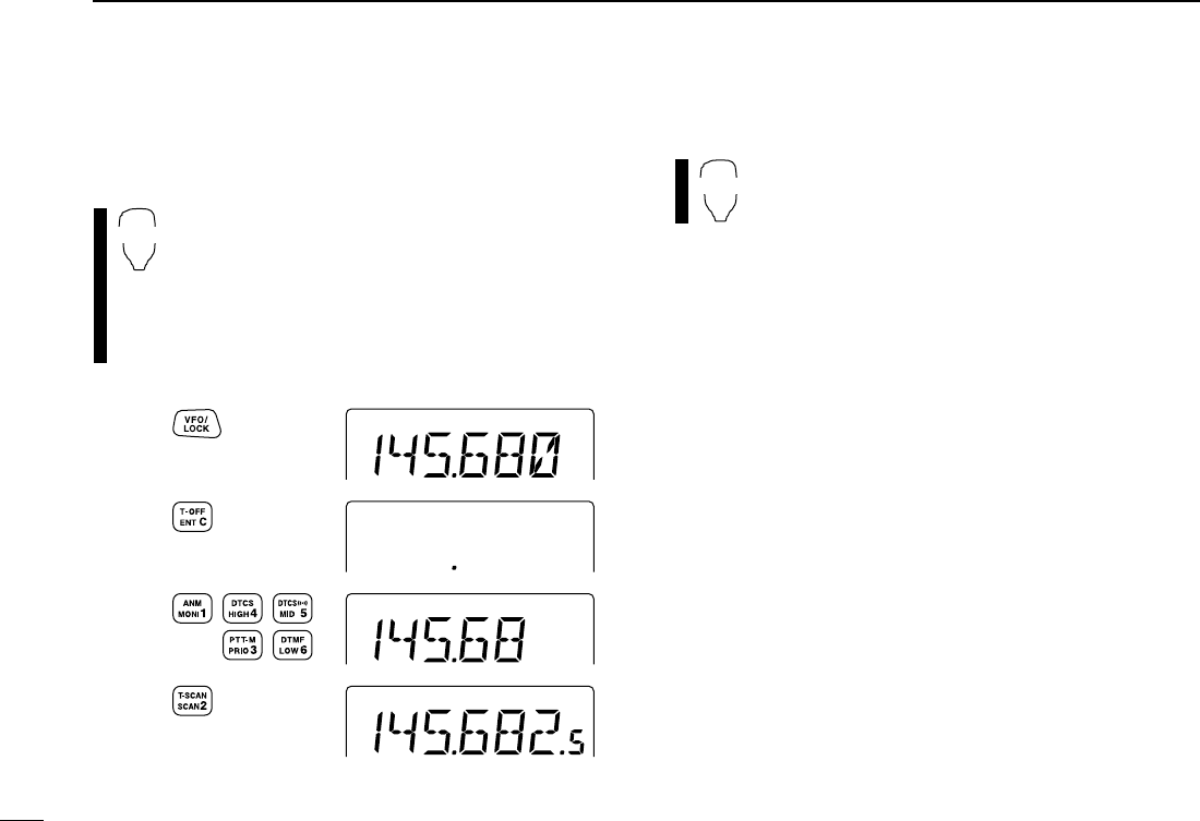
■Using the keypad
The frequency can be directly set via numeral keys on the mi-
crophone.
zPush [VFO/LOCK] to VFO mode, if necessary.
xPush [
ENT
C] to activate the keypad for digit input.
cPush 6 keys to input a frequency.
•When a digit is mistakenly input, push [
ENT
C] to clear
the input, then repeat input from the 1st digit.
•Pushing [
CLR
A] clears input digits and retrieves the
frequency.
■Using the [Y]/[Z] keys
➥Push [Y] or [Z] to select the desired frequency.
•Pushing [Y] or [Z] for more than 0.5 sec. activates a
scan. If scan starts, push [Y] or [Z] again to cancel it.
YZ
Push
Push
Push
Push
[EXAMPLE]: Setting frequency to 145.3625 MHz.
ENT
C
14
3
SETTING A FREQUENCY
1
2
3
4
5
6
7
8
9
10
11
12
13
14
15
16
17
18
19
20
21
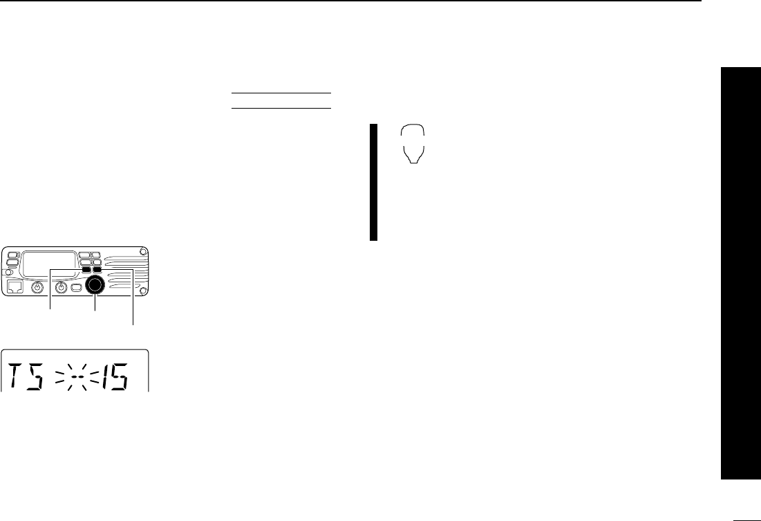
■Tuning step selection
Tuning steps are the minimum frequency change increments
when you rotate the tuning dial or push [Y]/[Z] on the micro-
phone. The following tuning steps are available.
•5 kHz •10 kHz •12.5 kHz •15 kHz
•20 kHz •25 kHz •30 kHz •50 kHz
☞NOTE: For convenience, select a tuning step that matches
the frequency intervals of repeaters in your area.
qPush [V/MHz(SCAN)] to se-
lect VFO mode, if neces-
sary.
wPush [SET(LOCK)] to enter
set mode.
ePush [SET(LOCK)] or
[MW(S.MW)] several times
until “TS” appears as shown
below.
•Cancel the DTMF memory
function in advance, if neces-
sary.
rRotate the tuning dial to se-
lect the desired tuning step.
tPush [V/MHz(SCAN)] to exit
set mode.
1Push [VFO/LOCK] to select VFO mode, if
necessary.
2Push [
SET
B] to enter set mode.
3Push [
SET
B] or [
ENT
C] several times until
“TS” appears.
4Push [Y] or [Z] to select the desired tuning
step.
5Push [
CLR
A] to exit set mode.
VFO/LOCK
[SET(LOCK)]
15 kHz tuning step
[MW(S.MW)]
Tuning dial
USING
SET MODE

15
3SETTING A FREQUENCY
■Lock functions
To prevent accidental channel changes and unnecessary
function access, use the lock function. The transceiver has 2
different lock functions.
DFrequency lock
This function locks the tuning dial and switches electronically
and can be used together with the microphone lock function.
➥Push [SET(LOCK)] for
1 sec. to turn the lock func-
tion ON and OFF.
•[PTT], [MONI(ANM)], [VOL]
and [SQL] can be used while
the channel lock function is in
use. Also, TONE-1, TONE-2,
DTMF tones or DTMF mem-
ory contents can be transmit-
ted from the microphone.
➥Push [VFO/LOCK] for 1 sec. to switch the
lock function ON and OFF.
DMicrophone keypad lock
This function locks the microphone keypad.
➥Push [FUNC] then [
SQL
ZD(16KEY-L)] to
switch the microphone keypad lock function
ON and OFF.
•[PTT], [VFO/LOCK], [MR/CALL], [BANK/OPTION],
[Y], [Z], [F-1], [F-2], [DTMF-S] and [FUNC] on the
microphone can be used.
•All switches on the transceiver can be used.
•The keypad lock function is released when the
power is turned OFF then ON again.
16KEY-L
VFO/LOCK
Push [SET(LOCK)] for 1 sec.
Appears
16
4
BASIC OPERATION
1
2
3
4
5
6
7
8
9
10
11
12
13
14
15
16
17
18
19
20
21
■Receiving
qPush [PWR] for 1 sec. to turn power ON.
wSet the audio level.
➥Push [MONI(ANM)] to open the squelch.
➥Rotate the [VOL] control to adjust the audio output level.
➥Push [MONI(ANM)] again to close the squelch.
eSet the squelch level.
➥Rotate [SQL] fully counterclockwise in advance.
➥Rotate [SQL] clockwise until the noise just disappears.
➥When interference is received, rotate [SQL] clockwise
again for attenuator operation.
rSet the operating frequency. (pgs. 00, 00)
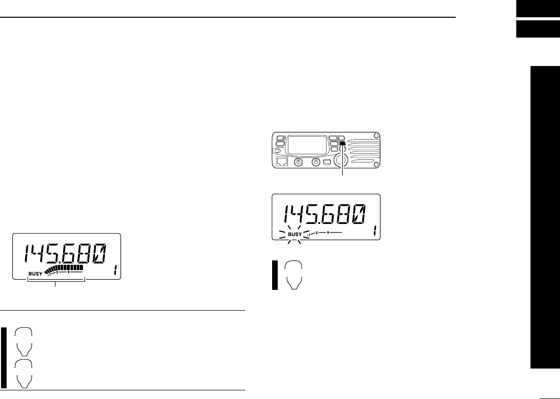
tWhen receiving a signal on the set frequency, squelch
opens and the transceiver emits audio.
•“BUSY” appears and the S/RF
indicator shows the relative
signal strength for the re-
ceived signal.
✔
CONVENIENT!
The squelch level can also be adjusted with
[
SQL
YD(MUTE)] and [
SQL
Z#(16KEY-L)] on the mi-
crophone.
■Monitor function
This function is used to listen to weak signals without disturb-
ing the squelch setting or to open the squelch manually even
when mute functions such as the tone squelch are in use.
➥Push [MONI(ANM)] to open
the squelch.
•“BUSY” flashes
•Push [MONI(ANM)] again to
cancel the function.
➥Push [
MONI
1] to open the squelch.
•Push [
MONI
1] again to cancel the function.
MONI
1
Push [MONI(ANM)]
SQLY
D
SQLZ
#
Appears when receiving a signal.
17
4BASIC OPERATION
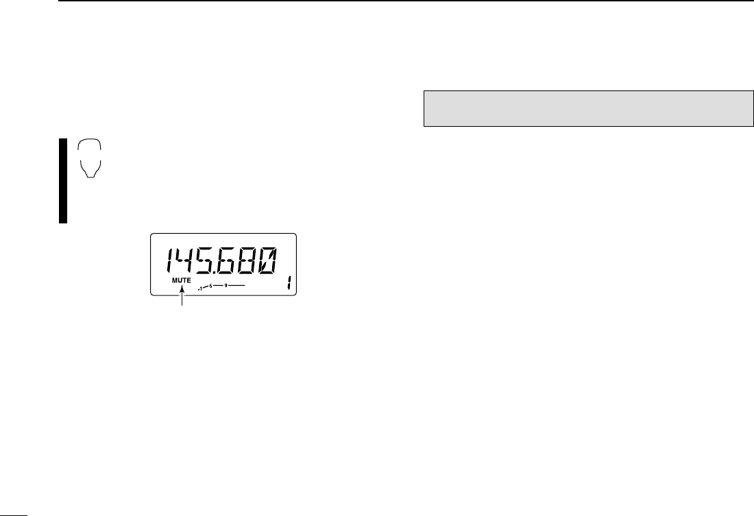
■Audio mute function
This function temporarily mutes the audio without disturbing
the volume setting.
zPush [FUNC] then [
SQL
YD(MUTE)] to mute
audio signals.
•“MUTE” appears.
xPush [
CLR
A] (or any other key) to cancel the
function.
•“MUTE” disappears.
■Squelch attenuator
The transceiver has an RF attenuator related to the squelch
level setting. Approx. 10 dB attenuation is obtained at maxi-
mum setting.
➥Rotate [SQL] clockwise past the 12 o’clock position to ac-
tivates the squelch attenuator.
•Attenuation level can be adjusted up to 10 dB (approx.) between
12 o’ckloc and fully clockwise position.
•When setting the squelch via from the microphone, the level “19”
or larger setting to acitivates the squelch attenuator.
■Transmitting
☞NOTE: To prevent interference, listen on the channel be-
fore transmitting by pushing [MONI(ANM)] or [
MONI
1] on
the microphone.
qSet the operating frequency. (pgs. 00, 00)
•Select output power if desired. See section at right for details.
wPush and hold [PTT] to transmit.
•“$” appears.
•The S/RF indicator shows the output power selection.
•A one-touch PTT function is available. See p. 00 for details.
eSpeak into the microphone using your normal voice level.
•DO NOT hold the microphone too close to your mouth or speak
too loudly. This may distort the signal.
rRelease [PTT] to return to receive.
CAUTION: Transmitting without an antenna will damage
the transceiver.
Appears
MUTE
18
4
BASIC OPERATION
1
2
3
4
5
6
7
8
9
10
11
12
13
14
15
16
17
18
19
20
21
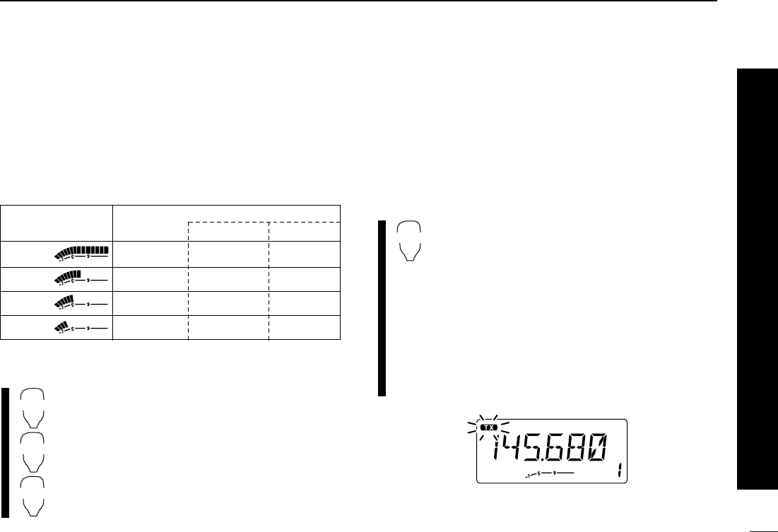
■Selecting output power
The transceiver has 4* output power levels to suit your oper-
ating requirements. Low output powers during short-distance
communications may reduce the possibility of interference to
other stations and will reduce current consumption.
*The Thailand and Taiwan versions have only 2 levels.
Push [LOW(DUP)] several times to select the output power.
•The output power can be changed while transmitting. *approx.
The microphone can also be used to select output power.
➥Push [
HIGH
4] for high output power; [
MID
5] for
middle high output power; and [
LOW
6] for low
output power.
•The output power CANNOT be changed via the mi-
crophone while transmitting.
■One-touch PTT function
The PTT switch can be operated as a one-touch PTT switch
(each push switches transmit/receive). Using this function you
can transmit without pushing and holding the PTT switch.
To prevent accidental, continuous transmissions with this
function, the transceiver has a time-out timer. See p. 00 for
details.
zPush [FUNC] then [
PRIO
3(PTT-M)] to turn the
one-touch PTT function ON.
•The activity indicator lights green.
xPush [PTT] to transmit and push again to re-
ceive.
•Two beeps sound when transmission is started and a
long beep sounds when returning to receive.
•“$” flashes when transmitting with the one-touch
PTT function.
cPush [FUNC] then [
PRIO
3(PTT-M)] to turn the
one-touch PTT function OFF.
•The activity indicator goes out.
PTT-M
HIGH
4
MID
5
LOW
6
S/RF INDICATOR POWER OUTPUT
Thailand Taiwan
70 W 10 W 25 W
25 W* N/A N/A
10 W* N/A N/A
5W* 5W* 5W*
High:
Mid.:
Mid. Low:
Low:
19
REPEATER OPERATION
1
2
3
4
5
6
7
8
9
10
11
12
13
14
15
16
17
18
19
20
21
5
■Accessing a repeater
qSet the receive frequency (repeater output frequency).
(pgs. 00–00)
wPush [LOW(DUP)] for 1 sec., one or two times, to select
minus duplex or plus duplex.
• “–” or “+” appears to indicate
the transmit frequency for
minus shift or plus shift, re-
spectively.
•When the auto repeater func-
tion is turned ON (available for
the USA version only), steps
wand eare not necessary.
(p. 00)
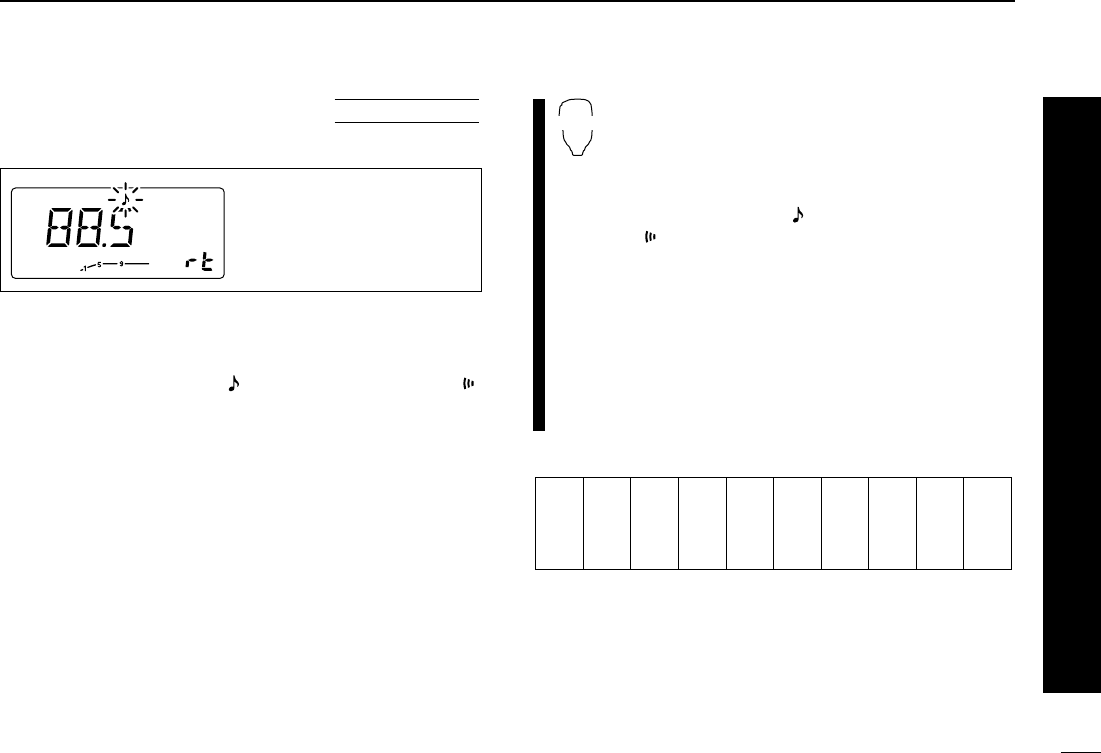
ePush [TONE(T-SCAN)] several times to turn ON the sub-
audible tone encoder, according to repeater requirements.
•
“” appears
•88.5 Hz is set to default; refer to p. 00 for tone frequency settings.
•When the repeater requires a different tone systems, see p. 00.
rPush and hold [PTT] to transmit.
•The displayed frequency automatically changes to the transmit
frequency (repeater input frequency).
•If
“OFF” appears, confirm that the offset frequency (p. 00) is set
correctly.
tRelease [PTT] to receive.
yPush [MONI(ANM)] to check weather the other station’s
transmit signal can be received directly.
uTo return to simplex operation, push [LOW(DUP)] for
1 sec., once or twice, to clear the “–” or “+” indicator.
iTo turn OFF the subaudible tone encoder, push [TONE(T-
SCAN)] several times until no tone indicators appear.
zSet the receive frequency (repeater output fre-
quency). (pgs. 00–00)
xPush [
DUP
–7] to select minus duplex; push
[
DUP
+ 8] to select plus duplex.
cPush [FUNC] then [
DUP
–7(TONE)] to turn ON
the subaudible tone encoder according to re-
peater requirements.
•Refer to p. 00 for the tone setting.
•When the repeater requires a different tone system,
see p. 00.
vPush and hold [PTT] to transmit.
bRelease [PTT] to receive.
nPush [
MONI
1] to check weather the other sta-
tion’s transmit signal can be received directly.
mTo return to simplex operation, push [
SIMP
9].
,To turn OFF the subaudible tone encoder, push
[FUNC] then [
ENT
C(T-OFF)].
DUP–
7
DUP+
8
SIMP
9
Either “–” or “+” appears.
■Subaudible tones
(Encoder function)
DSubaudible tones
qSelect the mode/channel you wish to set the subaudible
tones to, such as VFO mode or memory/call channel.
wPush [SET(LOCK)] until “” and “rt” appears; or until “”
and “Ct” appears for tone squelch or pocket beep use.
•Push [MONI(ANM)] to reverse the order of selection.
•Cancel the DTMF memory encoder function in advance, if nec-
essary. (p. 00)
eRotate the tuning dial to select and set the desired sub-
audible frequency.
rPush [V/MHz(SCAN)] to exit set mode.
☞NOTE: The subaudible tone encoder frequency can be set
in a memory channel temporarily. However, the set con-
tents are cleared once the memory/call mode is selected.
To store the tone frequency permanently, overwrite the
channel information.
zSet the mode/channel you wish to set the sub-
audible tone encoder frequency to, such as
VFO mode or memory/call channel.
•The subaudible tone frequency is independently pro-
grammed into each mode or channel.
xPush [
SET
B] until “” and “rt” appears; or until
“” and “Ct” appears for tone squelch or pocket
beep use.
•Pushing [
ENT
C] reverses the order of selection.
•Cancel the DTMF memory encoder function in ad-
vance, if necessary. (p. 00)
cPush [Y] or [Z] to select and set the desired
subaudible tone frequency.
•Push and hold [Y]/[Z] to change the above tones
continuously.
vPush [
CLR
A] to exit set mode.
•Subaudible tone frequency list (unit: Hz)
67.0
69.3
71.9
74.4
77.0
79.7
82.5
85.4
88.5
91.5
94.8
97.4
100.0
103.5
107.2
110.9
114.8
118.8
123.0
127.3
131.8
136.5
141.3
146.2
151.4
156.7
159.8
162.2
165.5
167.9
171.3
173.8
177.3
179.9
183.5
186.2
189.9
192.8
196.6
199.5
203.5
206.5
210.7
218.1
225.7
229.1
233.6
241.8
250.3
254.1
SET
B
USING
SET MODE
20
5
REPEATER OPERATION
1
2
3
4
5
6
7
8
9
10
11
12
13
14
15
16
17
18
19
20
21
The display shows that an
88.5 Hz subaudible CTCSS
tone frequency is set.
DDTMF tones
➥Push [DTMF-S], then push the keys of the de-
sired DTMF digits.
•The function indicator lights green.
•0–9, A–D, M(E) and #(F) are available.
•Cancel the DTMF memory encoder function in ad-
vance, if necessary. (p. 00)
•Push [DTMF-S] again to return the keypad to nor-
mal function control.
•The transceiver has 14 DTMF memory channels
for autopatch operation. See p. 00 for details.
D1750 Hz tone
The microphone has 1750 Hz tone capability,
used for ring tone when calling, etc.
zPush [FUNC].
•The mode indicator lights orange.
xPush [TONE-1] to transmit a 1750 Hz tone call
signal for 0.5 sec.; push and hold [TONE-2] to
transmit a 1750 Hz tone call signal for an arbi-
trary period.
•The mode indicator goes out automatically.
■Offset frequency
When communicating thorough a repeater, the transmit fre-
quency is shifted from the receive frequency by an amount
determined by the offset frequency.
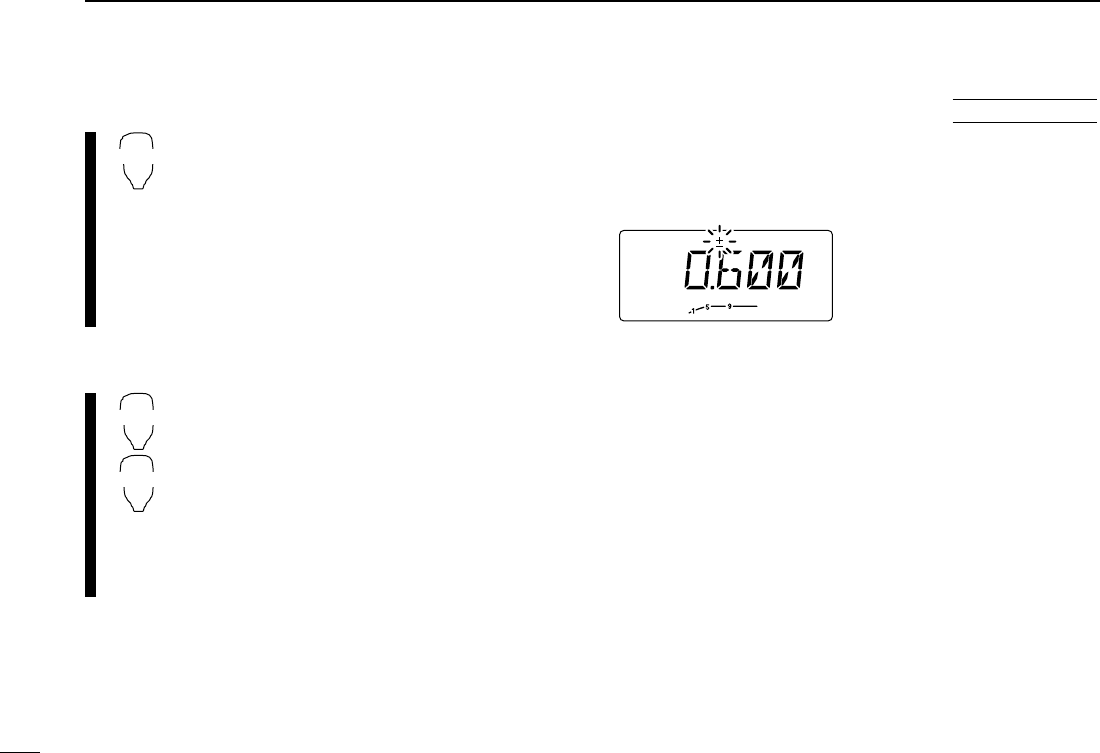
qPush [SET(LOCK)] to enter
set mode.
wPush [SET(LOCK)] until “±”
and offset frequency ap-
pear.
e
Rotate the tuning dial to set
the desired offset frequency.
rPush [V/MHz(SCAN)] to exit
set mode.
USING
SET MODE
TONE-1
TONE-2
DTMF-S
21
5REPEATER OPERATION
22
5
REPEATER OPERATION
1
2
3
4
5
6
7
8
9
10
11
12
13
14
15
16
17
18
19
20
21
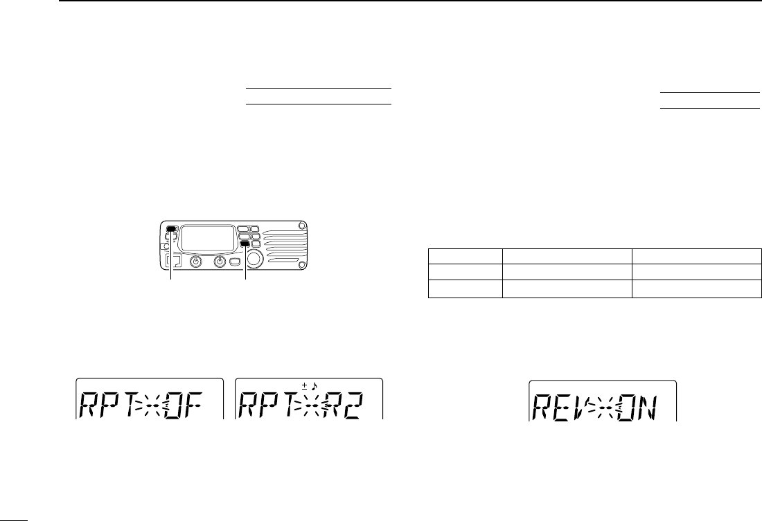
■Auto repeater
(USA version only)
The USA version automatically activates the repeater settings
(DUP– or DUP+ and tone encoder ON/OFF) when the operating
frequency falls within the general repeater output frequency
range and deactivates them when outside of the range.
DSetting the auto repeater function ON/OFF
qPush [PWR] to turn power OFF.
w
While pushing [SET(LOCK)], turn power ON to enter initial
set mode.
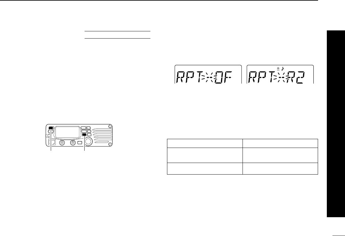
ePush [SET(LOCK)] several times until the “RPT” display
appears as shown below.
rRotate the tuning dial to turn the repeater lockout function
to “R1,” “R2” or OFF.
•“R1”: auto repeater is ON, tone encoder is OFF.
•“R2”: auto repeater is ON, tone encoder is ON.
tPush [PWR] to exit initial set mode.
DFrequency range and offset direction
Auto repeater function is
turned OFF.
Auto repeater function is ON,
tone encoder is ON.
While pushing [SET(LOCK)],
turn power ON.
USING
INITIAL SET MODE
Frequency range Duplex direction
145.200–145.495 MHz “–” appears
146.610–146.995 MHz
147.000–147.395 MHz “+” appears
■Repeater lockout
This function helps prevent interference to other stations by
inhibiting your transmission when a signal is received. The
transceiver has two inhibiting conditions, repeater and busy.
qPush [PWR] to turn power OFF.
wWhile pushing [SET(LOCK)], turn power ON to enter initial
set mode.
ePush [SET(LOCK)] several times until the “RLO” display
appears as shown below.
rRotate the tuning dial to turn the repeater lockout function
to “RP,” “BU” or OFF.
•“RP”: Transmit is inhibited when the tone squelch is closed.
•“BU”: Transmit is inhibited when a signal is received.
tPush [PWR] to exit initial set mode.
■Reversed duplex mode
When the reversed duplex mode is selected, the receive fre-
quency shifts. (Transmit frequency shifts in normal duplex mode.)
Each receive and transmit frequency is shown in the table
below with the following conditions;
Input frequency : 145.30 MHz
Direction : – (negative)
Offset frequency : 0.6 MHz
qPush [SET(LOCK] to enter set mode.
wPush [SET(LOCK)] several times until the “REV” display
appears as shown below.
rRotate the tuning dial to turn the repeater lockout function
to ON or OFF.
tPush [V/MHz(SCAN)] to exit set mode.
Reverse duplex mode is
turned ON.
USING
SET MODE
Auto repeater function is
turned OFF.
Auto repeater function is ON,
tone encoder is ON.
While pushing [SET(LOCK)],
turn power ON.
USING
INITIAL SET MODE
Reversed OFF ON
Rx frequency 145.30 MHz 144.70 MHz
Tx frequency 144.70 MHz 145.30 MHz
23
5REPEATER OPERATION
24
6
MEMORY OPERATION
1
2
3
4
5
6
7
8
9
10
11
12
13
14
15
16
17
18
19
20
21
■General description
The transceiver has 207 memory channels including 6 scan
edge memory channels (3 pairs), and 1 call channel. Each of
these channels can be individually programmed with operat-
ing frequency (p. 00), duplex direction (p. 00), subaudible
tone encoder or tone squelch and its tone frequency (pgs. 00,
00) and skip information.* (p. 00)
In addition, a total of 10 memory banks, A to J, are available
for making groups with usage, etc.
*except for scan edge memory channels.
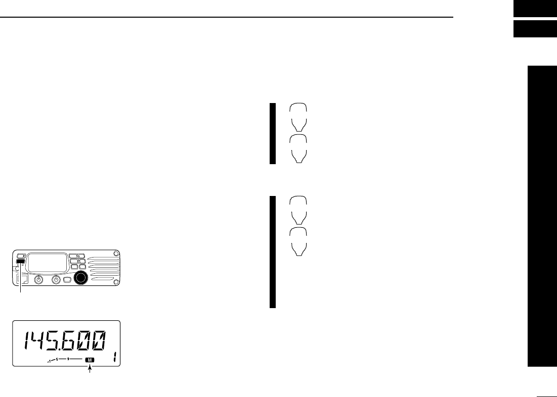
■Memory channel selection
DUsing the tuning dial
qPush [M/CALL(PRIO)]
once or twice to select
memory mode.
•“M” indicator appears
w
Rotate the tuning dial to
select the desired mem-
ory channel.
•Programmed memory
channel can only be se-
lected.
DUsing the [Y]/[Z] keys
zPush [MR/CALL] to select memory mode.
xPush [Y] or [Z] to select and set the desired
memory channel.
•Pushing [Y] or [Z] for more than 0.5 sec. acti-
vates a scan.
•
If scan is activated, push [Y] or [Z] again to stop it.
DUsing the keypad
zPush [MR/CALL] to select memory mode.
xPush [
ENT
C] to activate the keypad for nu-
meral input.
cPush 3 appropriate digit keys to input a chan-
nel number.
•When inputting non-programmed channel num-
bers, the previous memory channel appears.
•Push only 1 appropriate digit key, [
MONI
1], [
SCAN
2]
or [
PRIO
3], then push [
VOL
Z✱] or [
SQL
Z#] to se-
lect scan edge channels. “✱” and “#” can be used
for A and b respectively.
MR/CALL
Y/Z
MR/CALL
Y/Z
Push [M/CALL(PRIO)] to select
memory mode.
Appears

25
6MEMORY OPERATION
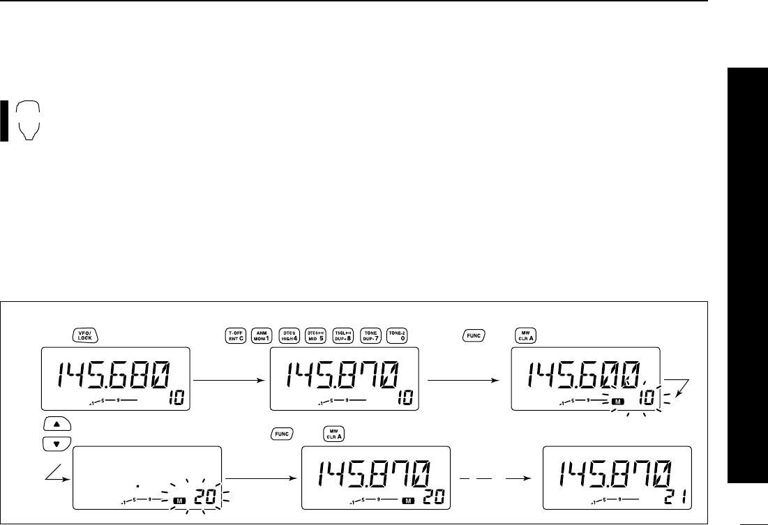
■Programming a memory channel
VFO settings, including the set mode contents such as sub-
audible tone frequency, etc., can programmed into a memory
channel.
qSet the desired frequency in VFO mode.
➥Push [V/MHz(SCAN)] to select VFO mode.
➥Set the frequency using the tuning dial.
➥Set other data (e.g. tone frequency, duplex information,
etc.) if required.
wPush [MW(S.MW)] momentarily.
•“M” indicator and the memory channel number blink.
eRotate the tuning dial to select the memory channel to be
programmed.
•Memory channels not yet programmed are blank.
rPush [MW(S.MW)] for 1 sec. to program.
•3 beeps sound
•Memory channel number automatically advances when contin-
uing to push [MW(S.MW)] after programming.
✔CONVENIENT
Memory programming can be performed in versatile ways
e.g. memory channel to the same (or different) memory chan-
nel, memory channel to the call channel, etc.
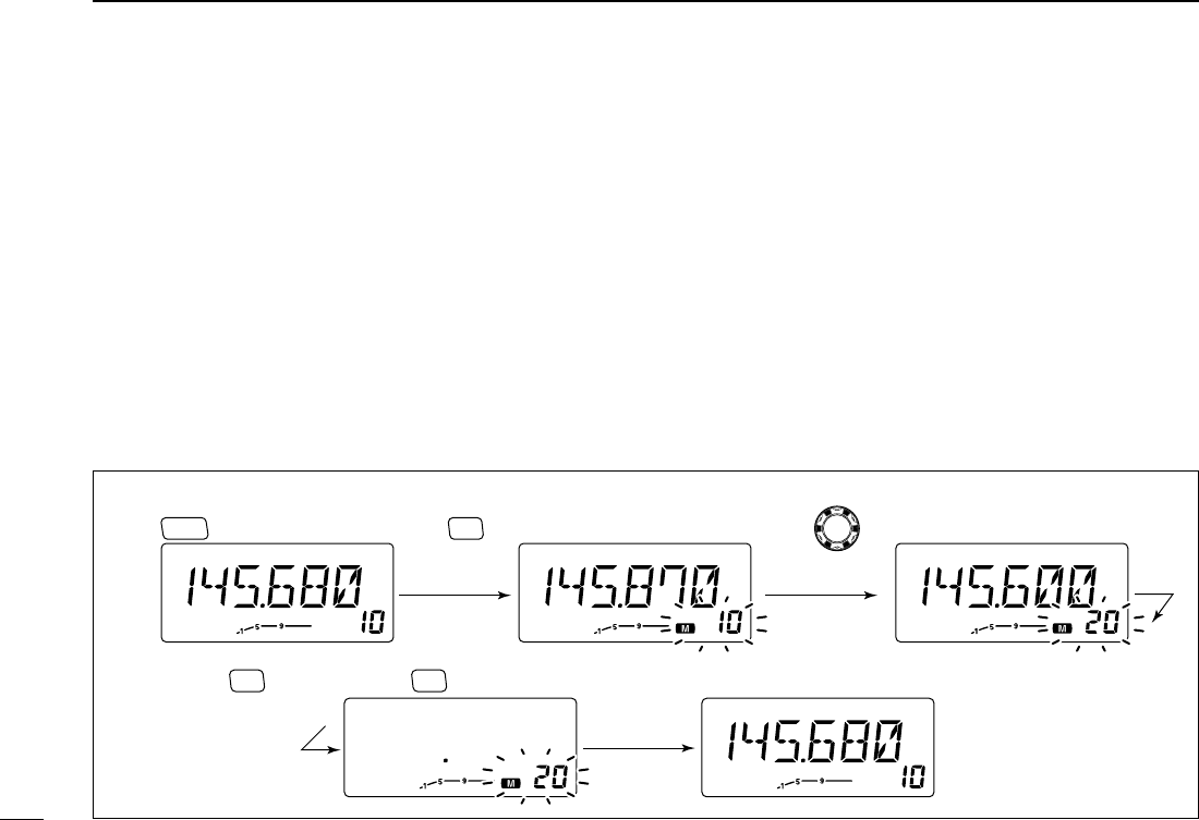
[EXAMPLE]: Programming 145.870 MHz into memory channel 20 (blank channel) via the front panel.
Push Rotate for setting frequency, etc. Push momentarily.
Rotate
V/MHz
SCAN S.MW
MW
Push for 1 sec. and continue to pushing
➠
S.MW
MW
Beep
Beep
Beep
“
“
“
“
“
26
6
MEMORY OPERATION
1
2
3
4
5
6
7
8
9
10
11
12
13
14
15
16
17
18
19
20
21
■Programming a memory channel via the microphone
[EXAMPLE]: Programming 145.870 MHz into memory channel 20 (blank channel) via the microphone.
Push Push Push then momentarily.
Push Push then 1 sec. and continue to pushing
➠
Beep
Beep
Beep
“
“
“
“
“
The microphone can also be used to program mem-
ory channels.
zSet the desired frequency in VFO mode.
➥Push [VFO/LOCK] to select VFO mode.
➥Set the frequency using the keypad.
➥Set other data (e.g. offset frequency, duplex direction, sub-
audible tone encoder ON/OFF and its frequency), if neces-
sary.
xPush [FUNC], then [
CLR
A(MW)] momentarily.
cSelect the memory channel to be programmed.
➥Push [Y] or [Z] to select the memory channel (direct nu-
meral input cannot be used).
vPush [FUNC] then [
CLR
A(MW)] for 1 sec. to program.
➥3 beeps may sound and the VFO contents (including
the subaudible tone frequency, etc.) are programmed.
➥Memory channel number advances when continuing to
push [
CLR
A(MW)] after programming.
MW
27
6MEMORY OPERATION
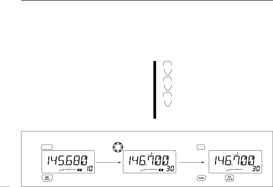
■
Transferring memory contents
This function transfers a memory channel’s contents to VFO
(or another memory/call channel). This is useful when search-
ing for signals around a memory channel frequency and for
recalling the offset frequency, subaudible tone frequency etc.
DMemory/call➪VFO
qSelect the memory/call channel to be transferred.
➥
Push [M/CALL(PRIO)] to select memory mode, then ro-
tate the tuning dial to select the desired memory channel.
➥
Push [M/CALL(PRIO)] for 1 sec. to select the call channel.
wPush [MW(S.MW)] for 1 sec. to transfer the selected mem-
ory/call channel contents to the VFO.
•VFO mode is selected automatically.
zSelect the memory/call channel to be
transferred.
➥Push [MR/CALL] to select memory mode,
then select the desired memory channel
via [Y]/[Z] or keypad.
➥Push [MR/CALL] for 1 sec. to select the
call channel.
xPush [FUNC], then [
CLR
A(MW)] for 1 sec. to
transfer the selected memory/call channel
contents to the VFO.
•VFO mode is selected automatically.
MR/CALL
MW
[Y]/[Z]
[EXAMPLE]: Transferring memory channel 30 contents to VFO.
Push to select memory mode.
Push to select memory mode.
Rotate for selecting memory channel.
Select memory channel.
Push for 1 sec.
Push then push for 1 sec.
S.MW
MW
PRIO
M/CALL
28
6
MEMORY OPERATION
1
2
3
4
5
6
7
8
9
10
11
12
13
14
15
16
17
18
19
20
21
DMemory/call➪call/memory
qSelect the memory/call channel to be transferred.
➥
Push [M/CALL(PRIO)] to select memory mode, then ro-
tate the tuning dial to select the desired memory channel.
➥
Push [M/CALL(PRIO)] for 1 sec. to select the call channel.
wPush [MW(S.MW)] momentarily.
•“M” indicator and “– –” indication blink.
eRotate the tuning dial to select the target memory channel.
•“C” blinks when the call channel is selected.
•Scan edge channels, 1A/1b, 2A/2b, 3A/3b, can also be selected.
rPush [MW(S.MW)] for 1 sec. to transfer the selected mem-
ory/call channel contents to the target memory.
•The targeted memory and transferred contents are indicated.
zSelect the memory/call channel to be trans-
ferred.
➥Push [MR/CALL] to select memory mode,
then select the desired memory channel
via [Y]/[Z] or keypad.
➥Push [MR/CALL] for 1 sec. to select the
call channel.
xPush [FUNC], then [
CLR
A(MW)] momentarily.
•“M” indicator and “– –” indication blink.
cPush [Y]/[Z] to selected the target memory
channel.
•“C” blinks when the call channel is selected.
•Scan edge channels can also be selected.
•The keypad cannot be used for the selection.
vPush [FUNC] then push [
CLR
A(MW)] for
1 sec. to transfer the selected memory/call
channel contents to the target memory.
•The targeted memory and transferred contents
are indicated.
MR/CALL
MW
[Y]/[Z]
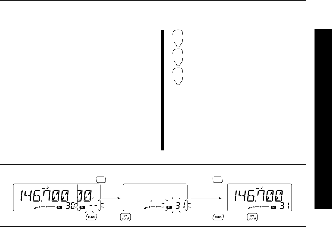
[EXAMPLE]: Transferring memory channel 30 contents to channel 31.
Select the target channel. Push for 1 sec.
Push then push for 1 sec.
S.MW
MW
Select the memory channel, then push .
S.MW
MW
Select the memory channel, push then push .
29
6MEMORY OPERATION
[EXAMPLE]: Clearing memory channel 20.
Push to select VFO. Rotate for selecting memory channel.Push momentarily.
V/MHz
SCAN S.MW
MW
Push any switch.Push briefly, then push again for 1 sec.
S.MW
MW S.MW
MW
Beep
Beep
Beep
“
“
“
“
“
■Memory clearing
Contents of programmed memories can be cleared (blanked),
if desired.
qPush [V/MHz(SCAN)] to select VFO mode.
wPush [MW(S.MW)] momentarily.
•“M” indicator and the memory channel number blink.
eRotate the tuning dial to select the memory channel to be
cleared.
•Memory channels not yet programmed are blank.
rPush [MW(S.MW)] briefly, then push [MW(S.MW)] again
for 1 sec.
•3 beeps sound, then the frequency is cleared.
•“M” indicator blinks continuously.
•Scan edges, 1A/1b, 2A/2b, 3A/3b, and the call channel cannot
be cleared.
☞This operation must be performed within 1.5 sec.
tPush any switch, except [MW(S.MW)], to return to VFO
mode.
☞NOTE: Be careful!— the contents of cleared memories
CANNOT be recalled.
30
6
MEMORY OPERATION
1
2
3
4
5
6
7
8
9
10
11
12
13
14
15
16
17
18
19
20
21
■Channel names programming
Each memory channel and the call channel can be pro-
grammed with an alphanumeric channel names for easy
recognition and can be indicated channel independent.
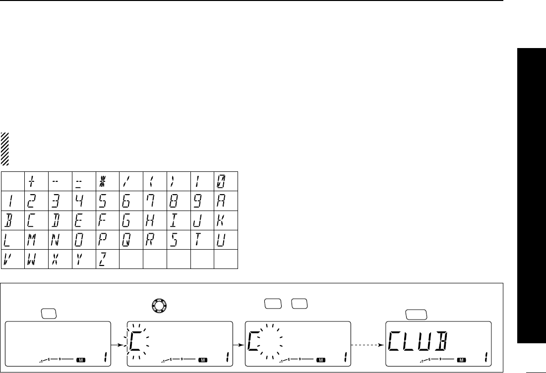
Names can be a maximum of 6 characters— see the table
below for available characters.
NOTE:
Scan edge channels CANNOT be programmed with al-
phanumeric channel names?
qPush [M/CALL(PRIO)] to select memory mode.
w
Rotate the tuning dial to select the desired memory channel.
ePush [MONI(ANM)] for 1 sec.
•3 beeps sound.
rPush [SET(LOCK)] to select the channel names program-
mable condition.
•Frequency readouts disappear.
tRotate the tuning dial to select the desired character.
•The selected character blinks.
yPush [SET(LOCK)] or [MW(S.MW)] to move the cursor to
left or right, respectively.
uRepeat steps tand yuntil the desired channel names
are displayed.
iPush [V/MHz(SCAN)] to program the name and exit chan-
nel names programmable condition.
oPush [MONI(ANM)] for 1 sec. to return to frequency indi-
cation if desired.
(1)
(B)
(L)
(V)
(+)
(2)
(C)
(
M
)
(
W
)
(–)
(3)
(
D
)
(N)
(X)
(=)
(4)
(E)
(O)
(Y)
(✱)
(5)
(F)
(P)
(Z)
(/)
(6)
(G)
(
Q
)
(space)
(7)
(<)
(
H
)
(
R
)
(>)
(8)
(I)
(S)
(|)
(9)
(J)
(T)
(0)
(A)
(
K
)
(U)
[EXAMPLE]: Programming “CLUB” into memory channel 1.
Push .
V/MHz
SCAN
Select memory channel 1,
then push for 1 sec.
MONI
ANM
Push or to move
the cursor.
SET
LOCK S.MW
MW
Rotate to select the
character.
Repeat
previous
steps.
31
6MEMORY OPERATION
Channel names can also be programmed via the mi-
crophone.
zSelect the memory/call channel to be assigned memory
names.
➥Push [MR/CALL] to select memory mode, then select
the desired memory channel via [Y]/[Z] or keypad.
•Scan edge channels can also be selected.
➥Push [MR/CALL] for 1 sec. to select the call channel.
xPush [FUNC], then [
MONI
1(ANM)] momentarily.
cPush [
SET
B(D-OFF)].
•Frequency readouts disappear.
vPush [Y]/[Z] to selected the desired character.
•The selected character blinks.
bPush [
SET
B(D-OFF)] or [
ENT
C(T-OFF)] to move the cur-
sor to left or right, respectively.
nRepeat steps band nuntil the desired channel names
are displayed.
mPush [
SET
B(D-OFF)] or [
ENT
C(T-OFF)] to move the cur-
sor to left or right, respectively.
,Push [
CLR
A(MW)] to program the name and exit channel
names programmable condition.
.Push [FUNC], then push [
MONI
1(ANM)] to return to fre-
quency indication if desired.
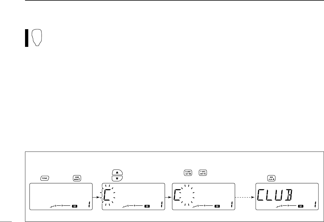
[EXAMPLE]: Programming “CLUB” into memory channel 1.
Repeat
previous
steps.
Push to select the character.
Select memory channel 1,
push , then push . Push .
Push or to move
the cursor.

32
6
MEMORY OPERATION
1
2
3
4
5
6
7
8
9
10
11
12
13
14
15
16
17
18
19
20
21
■Memory bank selection
qPush [M/CALL(PRIO)] to
select memory mode, if de-
sired.
wPush [BANK(OPT)] to se-
lect memory bank selecting
condition.
•Bank initial blinks
eRotate the tuning dial to se-
lect the desired bank.
•Initials which no contents are
progemmed banks are
skipped.
rPush [BANK(OPT)] to set
the bank.
•Stop blinking.
tRotate the tuing dial to se-
lect the contents in the
bank.
•No channel numbers are dis-
layed for memory bank opera-
tion.
yTo return to regular memory
condition, push [BANK(OPT)]
twice.
zPush [MR/CALL] to select memory mode,
if desired.
➥Push [MR/CALL] for 1 sec. to select the
call channel.
xPush [BANK/OPTION] to select memory
bank selecting condition.
•Bank initial blinks
cPush [Y]/[Z] to select the desired bank.
•Initials which no contents are programmed
banks are skipped.
vPush [BANK/OPTION] to set the bank.
•Stop blinking.
bPush [Y]/[Z] to select the desired contents
in the bank.
•No channel numbers are displayed for memory
bank operation.
nTo return to regular memory condition,
push [BANK/OPTION] twice.
BANK/OPTION
[Y]/[Z]
Push [BANK(OPT)] to select
memory bank mode.
Shows bank initial.
33
6MEMORY OPERATION
■Memory bank setting
qPush [MR/CALL] to select memory mode, then select the
desired memory channel via the tuning dial.
wPush [BANK(OPT)].
•“M” and “– –” indication blink as follow.
ePush [BANK(OPT)] again to set the channel to bank set-
ting stand-by condition.
•“M” and “– –” indication blinking stop.
rPush [MW(S.MW)] then rotate the tuning dial to select the
desired bank to be set.
•Bank initial blinks as follow.
tPush [MW(S.MW)] again to set the channel into the bank.
•Bank initial blinking stops.
yPush [BANK(OPT)] twice to return to regular memory con-
dition.
uRepeat steps qto yto set an another memory channel
into the same or another bank.
zPush [MR/CALL] then select the desired
memory channel via [Y]/[Z] or keypad.
xPush [BANK/OPTION].
•“– –” indication blinks.
cPush [BANK/OPTION] again to set the
channel to bank setting stand-by condition.
•“– –” indication blinking stops.
vPush [FUNC] then [
CLR
A(MW)] then push
[Y]/[Z] to select the desired bank to be
set.
•Bank initial blinks.
bPush [
CLR
A(MW)] to set the channel into
the bank.
•Bank initial blinking stops.
nPush [BANK/OPTION] twice to return to
regular memory channel condition.
mRepeat steps zto nto set an another
memory channel into the same or another
bank.
BANK/OPTION
MW
[Y]/[Z]
Blinks
S.MW
MW
Blinks
OPT
BANK
34
6
MEMORY OPERATION
1
2
3
4
5
6
7
8
9
10
11
12
13
14
15
16
17
18
19
20
21
■Transferring bank contnts
For erasing contents from bank or transferring contents to an
another bank, bank contents transfer is available.
qSelect the desired bank contents to be transferred or
erased.
➥Push [MR/CALL] to select memory mode.
➥Push [BANK(OPT)] then rotate the tuning dial to select
the desired memory bank.
•“M” and bank initial blink.
➥Push [BANK(OPT)] to select the bank then rotate the
tuning dial to select the desired contents.
•“M” and bank initial blinking stop.
wPush [MW(S.MW)] momentarily.
•“M” and bank initial blink.
eRotate the tuning dial to select the desired bank initial to
transfer or erase.
•Select “– –” indication when erasing the contents from the bank.
rPush [MW(S.MW)] again.
•“M” and bank initial or “– –” indication blinking stop.
tPush [BANK(OPT)] twice to return to regular memory con-
dition.
yRepeat steps qto tto transferring or erasing an another
bank contents.
zSelect the desired bank contents.
➥Push [MR/CALL] to select memory
mode.
➥Push [BANK/OPTION] then select the
desired memory bank via [Y]/[Z].
➥Push [BANK/OPTION] to select the
bank then select the desired contents
via [Y]/[Z].
xPush [FUNC] then [
CLR
A(MW)].
•“M” and bank initial blinks.
cPush [Y]/[Z] to select the desired bank ini-
tial to transfer or erase.
•Select “– –” indication when erasing the con-
tents from the bank.
vPush [
CLR
A(MW)].
•“M” and bank initial or “– –” indication blinking
stop.
bPush [BANK/OPTION] twice to return to
regular memory condition.
nRepeat steps zto bto transferring or
erasing an another bank contents.
BANK/OPTION
MW
[Y]/[Z]
Blinks
OPT
BANK
35
CALL CHANNEL OPERATION
1
2
3
4
5
6
7
8
9
10
11
12
13
14
15
16
17
18
19
20
21
7
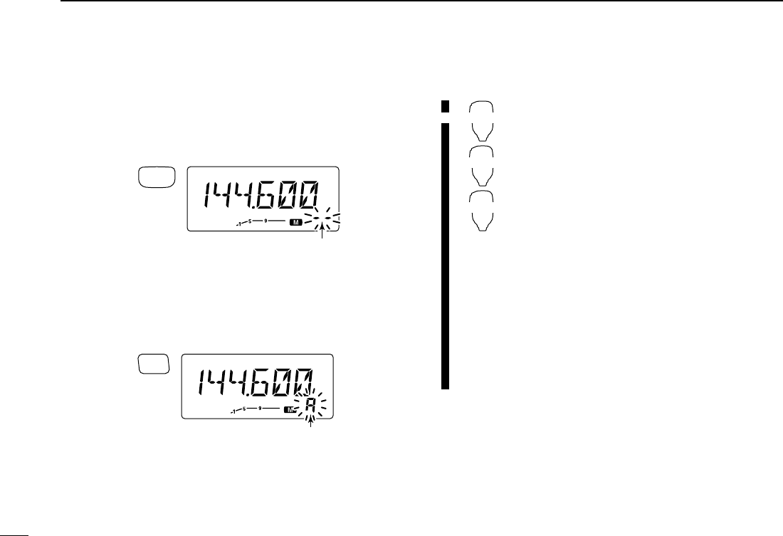
■Call channel selection
➥Push [M/CALL(PRIO)] sev-
eral times to select the call
channel.
•“C” appears instead of mem-
ory channel number indication.
•Push [M/CALL(PRIO)] once or
twice to select memory mode,
or push [V/MHz(SCAN)] to se-
lect VFO mode.
➥Push [MR/CALL] for 1 sec. to select the call
channel.
•Push [MR/CALL] to select memory mode, or push
[VFO/LOCK] to select VFO mode.
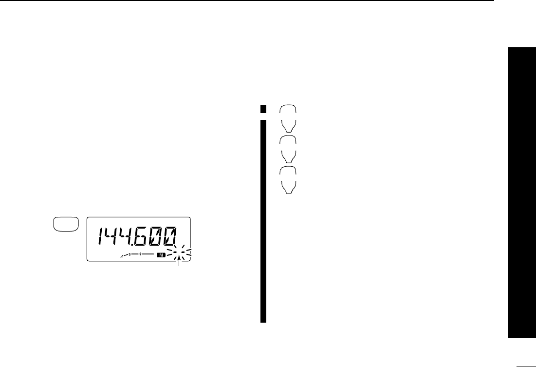
■Call channel transferring
qPush [M/CALL(PRIO)] several times to select the call
channel.
•Large “C” appears.
wPush [MW(S.MW)] momentarily, then rotate the tuning dial
to select the memory channel to transfer the contents to.
•To transfer to the VFO, push [MW(S.MW)] for 1 sec.
ePush [MW(S.MW)] for 1 sec. to transfer when a momen-
tary push was used in the previous step.
•If channel names have been programmed into the call channel,
the names also transferred.
zPush [MR/CALL] for 1 sec. to select the call
channel.
xPush [FUNC], [
CLR
A(MW)] momentarily, then
push [Y]/[Z] to select the memory channel to
transfer the contents to.
•To transfer to the VFO, push [FUNC], then push
[
CLR
A(MW)] for 1 sec.
cPush [FUNC], then [
CLR
A(MW)] for 1 sec. to
transfer when a momentary push was used in
the previous step.
vPush [MR/CALL] for 1 sec. to select the call
channel.
•If channel names have been programmed into the
call channel, the names also transferred.
MR/CALL
MW
[Y]/[Z]
MR/CALL
Push [M/CALL(PRIO)] several
times to select the call channel.
Appears
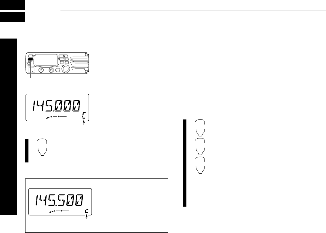
✔INFORMATION
When the VFO mode is se-
lected from the call channel,
small “c” appears instead of
memory channel number.
Small “C” shows VFO was
selected from the call channel.
36
7
CALL CHANNEL OPERATION
1
2
3
4
5
6
7
8
9
10
11
12
13
14
15
16
17
18
19
20
21
■Programming a call channel
In addition to an operating frequency, duplex information, sub-
audible to information (ton encoder or tone squelch ON/OFF
and its frequency) and an alphanumeric channel names can
be programmed into the call channel.
qSet the desired frequency in VFO mode.
➥Push [V/MHz(SCAN)] to select VFO mode.
➥Set the frequency using the tuning dial.
➥Set other data as desired.
wPush [MW(S.MW)] momentarily.
eRotate the tuning dial to select the call channel
•“M” indicator and large “C” blink.
rPush [MW(S.MW)] for 1 sec. to program.
•3 beeps sound and return to VFO mode automatically.
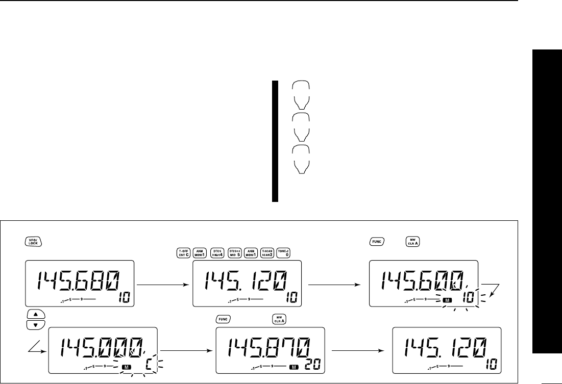
zSet the desired frequency in VFO mode.
➥Push [VFO/LOCK] to select VFO mode.
➥Set the frequency.
➥Set other data as desired.
x
Push [FUNC], then [
CLR
A(MW)] momentarily.
cSelect the call channel via [Y] or [Z] .
vPush [FUNC] then [
CLR
A(MW)] for 1 sec. to
program.
•3 beeps sound and the return to VFO mode auto-
matically.
MR/CALL
MW
[Y]/[Z]
[EXAMPLE]: Programming 145.120 MHz into the call channel via the microphone.
Set the frequency.
Push to select VFO mode. Push , then .
Push , then push for 1 sec.
➠
Push until large “C” appears.
Beep
Beep
Beep
“
“
“
“
“
37
SCAN OPERATION
1
2
3
4
5
6
7
8
9
10
11
12
13
14
15
16
17
18
19
20
21
8
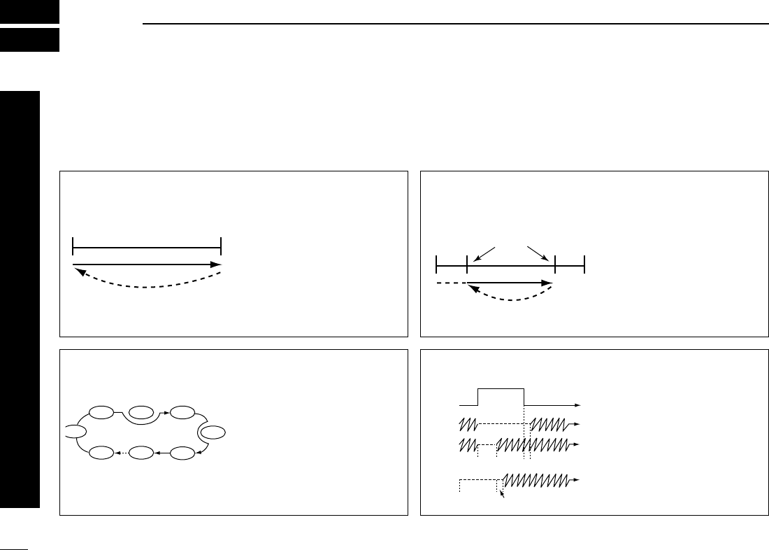
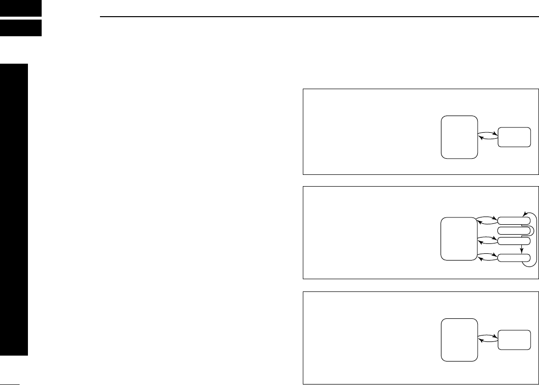
■Scan types
Scanning searches for signals automatically and makes it
easier to locate new stations for contact or listening purposes.
There are 3 scan types and 5 resume conditions to suit your
operating needs.
FULL SCAN (p. 00) Repeatedly scans all frequen-
cies over the entire band.
Used as the simplest scan
without any preliminary set-
tings necessary.
Band
edge
Band
edge
Scan
Jump
PROGRAMMED SCAN
(p. 00)
Repeatedly scans between
two user-programmed fre-
quencies. Used for checking
for frequencies within a speci-
fied range such as repeater
output frequencies, etc. 3
pairs of scan edges are avail-
able.
Band
edge
Band
edge
Scan edges
Scan
Jump
MEMORY SCAN (p. 00) Repeatedly scans memory
channels except those set as
skip channels. Used for often-
called channels and for by-
passing normally busy
channels such as repeater
frequencies.
SKIP
SKIP
M 0 M 4
M 1 M 2 M 3
M 5
M 199
M 6
SCAN RESUME
CONDITION (p. 00)
5 resume conditions are avail-
able: 3 timer scans, pause
scan and empty scan. When
receiving a signal, pause
scan pauses until the signal
disappears; timer scans
pause for 5, 10 or 15 sec.
Empty pause scan pauses
until a signal appears.
Pause
scan
Receiving
a signal
Timer
scan
Empty
pause
scan
Pausing
Pausing
2 sec.
2 sec.
☞NOTE: A tone scan function is available to search for subaudible tones (e.g. when you want to find a subaudible tone fre-
quency necessary to open a repeater). See p. 00 for details.
38
8
SCAN OPERATION
1
2
3
4
5
6
7
8
9
10
11
12
13
14
15
16
17
18
19
20
21
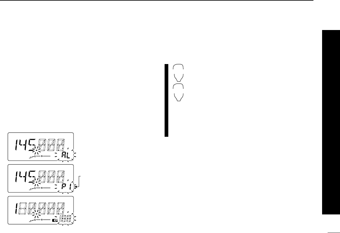
■Scan start/stop
DPreparation
Scan resume condition (p. 00); program the scan edges
(p. 00); program 2 or more memory channels (p. 00); set skip
settings, if desired (p. 00)
DOperation
qSelect VFO mode for full/programmed scan with
[V/MHz(SCAN)]; or memory mode for memory scan with
[M/CALL(PRIO)].
wSet the squelch to the point where noise is just muted.
ePush [V/MHz(SCAN)] for 1 sec. to start the scan.
•To change the scanning direction, rotate the tuning dial.
•The memory channel readout blinks the scan type as follows:
rPush [SET(LOCK)] to switch full and programmed scan.
tTo stop the scan, push [V/MHz(SCAN)].
zPush [VFO/LOCK] to select VFO mode for
full/programmed scan; push [MR/CALL] to select
memory mode for memory scan.
xSet the squelch to the point where noise is just
muted.
cPush [
SCAN
2(T-SCAN)] to start the scan.
•Push [Y] or [Z] for 1 sec. also starts the scan.
vPush [
SET
B(D-OFF)] to switch full and pro-
grammed scan.
bTo stop the scan push [
SCAN
2(T-SCAN)] or
[
CLR
A(MW)].
SCAN
2
SET
B
During full scan
During programmed scan
During memory scan
Indicates scan edge channels.
• P1 stands for 1A/1b
• P1 to P3 are available when
they are programmed.
Push [SET(LOCK)] to select full
or programmed scan in
sequence.
39
8SCAN OPERATION
■Scan edges programming
Scan edges can be programmed in the same manner as
memory channels. Scan edges are programmed into scan
edges, 1A/1b to 3A/3b, in memory channels.
qSet the edge frequency of the desired frequency range in
VFO mode:
➥Set the frequency using the tuning dial.
➥Set other data (e.g. repeater settings, etc.) if desired.
wPush [MW(S.MW)] momentarily.
•“M” indicator and channel number blink.
eRotate the tuning dial to select one of scan edge channel,
1A, 2A or 3A.
rPush [MW(S.MW)] for 1 sec. to program.
•3 beeps sound and the frequency is programmed.
•Scan edge 1b, 2b or 3b is automatically selected when continu-
ing to push [MW(S.MW)] after programming.
tTo program a frequency for the other pair of scan edges,
1b, 2b or 3b, repeat steps eand r.
•If the same frequency is programmed into a pair of scan edges,
programmed scan will not function.
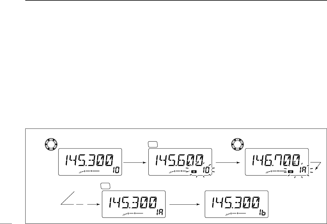
[EXAMPLE]: Programming 145.300 MHz and 145.800 MHz into scan edges 1A and 1b, respectively.
Push momentarily.Rotate for setting frequency, etc. Rotate
S.MW
MW
Push for 1 sec. and continue to pushing
➠
S.MW
MW
Beep
Beep
Beep
“
Beep
“
“
“
“
“
40
8
SCAN OPERATION
1
2
3
4
5
6
7
8
9
10
11
12
13
14
15
16
17
18
19
20
21
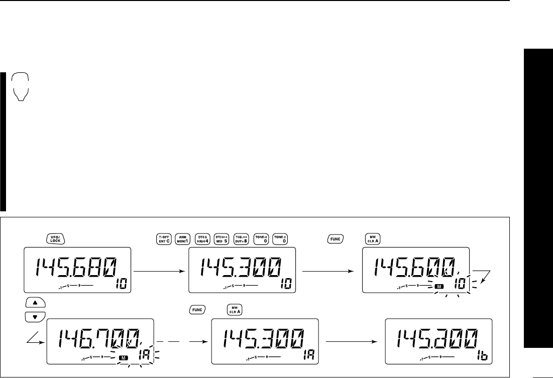
■Scan edges programming via microphone
zSet the desired frequency in VFO mode.
➥Push [VFO/LOCK] to select VFO mode.
➥Set the frequency via the keypad or [Y]/[Z].
xPush [FUNC] then [
CLR
A(MW)] momentarily.
cPush [Y] or [Z] to select scan edge channels,
1A, 2A or 3A.
vPush [FUNC], then push [
CLR
A(MW)] for 1 sec.
to program.
•3 beeps may sound and the VFO contents are pro-
grammed.
•Memory channel number advances to the next scan
edge channel, 1b, 2b or 3b, when continuing to push
[
CLR
A(MW)] after programming.
bTo program a frequency for the other scan edge channel,
repeat steps zto v.
MW
[EXAMPLE]: Programming 145.300 MHz and 145.800 MHz into scan edges 1A and 1b, respectively.
Push Push Push then momentarily.
Push Push then 1 sec. and continue to pushing
➠
Beep
“
Beep
Beep
Beep
“
“
“
“
“
41
8SCAN OPERATION
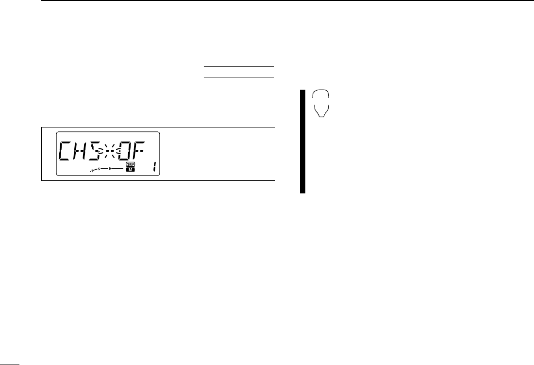
■Skip channel setting
The memory skip function speeds up scanning by checking
only those memory channels not set as skip channels. Set
skip channels as follows.
qSelect a memory channel:
➥Push [M/CALL(PRIO)] to select memory mode.
➥Rotate the tuning dial to select the desired channel to
be a skip channel.
wPush [SET(LOCK)] to enter set mode.
ePush [SET(LOCK)] or [MW(S.MW)] several times until
“CHS” appears as shown above.
rRotate the tuning dial to turn the skip function ON or OFF
for the selected channel.
•“~” appears : The channel is skipped during scan.
(CHS-ON)
•“~” disappears : The channel is scanned during scan.
(CHS-OFF)
tPush [V/MHz(SCAN)] to exit set mode.
zSelect a memory channel.
➥Select memory mode by pushing [MR/CALL].
➥Push [Y] or [Z] to select the desired channel
to be a skip channel.
xPush [
SET
B(D-OFF)] to enter set mode.
cPush [
SET
B(D-OFF)] or [
ENT
C(T-OFF)] several
times until “CHS” appears as shown at left.
vPush [Y] or [Z] to set or cancel the skip setting.
•See item rat left for skip indicator details.
bPush [
CLR
A(MW)] to exit set mode.
☞NOTES:
Even through scan edge channels cannot be set as skip
channels, the ARE skipped during memory scan.
SET mode cannot be accessed when memory names are
displayed. To set the scan resume condition, return to
channel number indication by pushing [MONI(ANM)] on
the front panel for 1 sec., or push [FUNC] then
[
MONI
1(ANM)] to cancel the channel name indication, then
set as describes above.
SET
B
The display shows that
memory channel 1 is set
as a skip channel.
USING
SET MODE
42
8
SCAN OPERATION
1
2
3
4
5
6
7
8
9
10
11
12
13
14
15
16
17
18
19
20
21
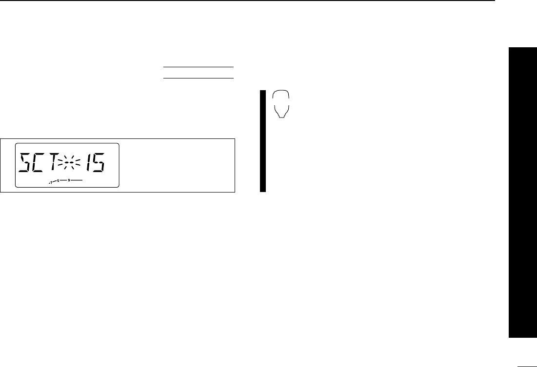
■Scan resume condition
The scan resume condition can be selected as timer, pause
or empty pause scan. The empty pause scan is useful for
finding unused channels. The selected resume condition is
also used for priority watch. (p. 00)
qPush [SET(LOCK)] to enter set mode.
wPush [SET(LOCK)] or [MW(S.MW)] several times until
“SCT” or “SCP” appears as shown above.
•Cancel the DTMF memory encoder in advance, if necessary.
(p. 00)
eRotate the tuning dial to set the desired timer:
•“SCT-15”: Scan pauses 15 sec. while receiving a signal.
•“SCT-10”: Scan pauses 10 sec. while receiving a signal.
•“SCT-5”: Scan pauses 5 sec. while receiving a signal.
•“SCP-2”: Scan pauses until the signal disappears and then
resumes 2 sec. later.
rPush [V/MHz(SCAN)] to exit set mode.
zPush [
SET
B(D-OFF)] to enter set mode.
xPush [
SET
B(D-OFF)] or [
ENT
C(T-OFF)] several
times until “SCT” or “SCP” appears as shown at
left.
•Cancel the DTMF memory encoder in advance, if
necessary. (p. 00)
cPush [Y] or [Z] to select the scan resume condi-
tion.
•See item eat left for scan resume condition details.
vPush [
CLR
A(MW)] to exit set mode.
☞NOTE:
SET mode cannot be accessed when memory names are
displayed. To set the scan resume condition, return to
channel number indication by pushing [MONI(ANM)] on
the front panel for 1 sec., or push [FUNC] then
[
MONI
1(ANM)] to cancel the channel name indication, then
set as describes above.
SET
B
The display shows that the
scan will resume 15 sec.
after it stops.
USING
SET MODE
43
PRIORITY WATCH
1
2
3
4
5
6
7
8
9
10
11
12
13
14
15
16
17
18
19
20
21
9
■Priority watch types
Priority watch checks for signals on a call channel every
5 sec. while operating on a memory channel. The transceiver
has 2 priority watch types to suit your needs. You can transmit
on the memory channel while the priority watch operates.
The watch resumes according to the selected scan resume
condition. See previous page for details.
☞NOTES:
➧If the DTMF memory encoder is activated, it is automati-
cally cancelled when priority watch starts.
➧If the pocket beep function is activated, the transceiver
automatically selects the tone squelch function when pri-
ority watch starts.
MEMORY CHANNEL WATCH
While operating on a VFO fre-
quency, priority watch checks for
a signal on the selected memory
channel every 5 sec.
MEMORY SCAN WATCH
While operating on a VFO
frqeuency, priority watch checks
for signals on each memory
channel in sequence.
•The memory skip function is useful
to speed up the scan.
5 sec.
VFO
frequency
125 msec.
Memory
channel
5 sec. 125 msec.
VFO
frequency
SKIP
Mch 1
Mch 2
Mch 3
Mch 199
CALL CHANNEL WATCH
While operating on a VFO
frqeuency, priority watch checks
for signals on the call channel
every 5 sec.
5 sec.
VFO
frequency
125 msec.
Call
channel

44
9
PRIORITY WATCH
1
2
3
4
5
6
7
8
9
10
11
12
13
14
15
16
17
18
19
20
21
■Priority watch operation
qSelect memory mode; then, set an operating frequency.
wSet the watching channel(s).
For memory channel watch:
Select the desired memory channel.
For memory scan watch:
Select memory mode; then, push [V/MHz(SCAN)] for
1 sec. to start memory scan.
For call channel watch:
Select the call channel by pushing [M/CALL(PRIO)] once
or twice.
ePush [M/CALL(PRIO)] for 1 sec. to start the watch.
•The transceiver checks the memory or call channel every 5 sec.
•The watch resumes according to the selected scan resume con-
dition. (p. 00)
•While the watch is pausing, pushing [M/CALL(PRIO)] resumes
the watch manually.
rPush [M/CALL(PRIO)] while the display shows the mem-
ory channel to stop the watch.
zSelect memory mode; then, set an operating fre-
quency.
xSet the watching channel(s).
For memory channel watch:
Push [MR/CALL] then [Y] or [Z] to select the de-
sired call channel.
For memory scan watch:
Push [MR/CALL], then push [
SCAN
2] to start the
memory scan.
For call channel watch:
Push [MR/CALL] for 1 sec. to select the call
channel.
cPush [
PRIO
3(PTT-M)] to start the watch.
•The transceiver checks the memory or call channel
every 5 sec.
•The watch resumes according to the selected scan re-
sume condition. (p. 00)
•To resume the watch manually when paused, push
[
PRIO
3(PTT-M)] or [
CLR
A(MW)].
vTo stop the watch, push [
CLR
A(MW)] once (or
twice while watch is paused).
PRIO
3
While pausing or receiving
a signal on the memory or
call chanel, “PRIO” blinks.
45
DTMF MEMORY ENCODER
1
2
3
4
5
6
7
8
9
10
11
12
13
14
15
16
17
18
19
20
21
10
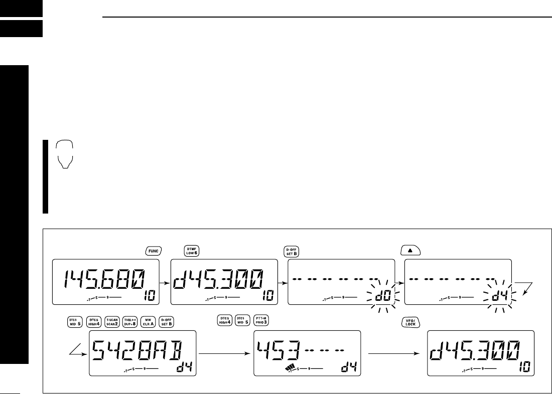
■Programming a DTMF code
DTMF codes are used for autopatching, controlling other
equipment, etc. The transceiver has 10 DTMF memory chan-
nels (d0–d9) for storage of often-used DTMF codes of up to
24 digits.
zPush [FUNC] then [
LOW
6(DTCS)] to turn the
DTMF encoder ON.
•“d” appears in place of the 100 MHz digit.
xPush [
SET
B(D-OFF)] to enter the DTMF mem-
ory programming condition.
cPush [Y] or [Z] to select the desired DTMF
memory channel.
vPush the desired digit keys.
•When the first digit is input, previous memory contents are
cleared automatically.
•“E” stands for “M” and “F” stands for “# .”
•Push [Y]/[Z] and repeat this step if you make a mistake.
•The S/RF indicator shows the digit group. The indication in-
creases every 6 digits.
bPush [VFO/LOCK] to exit the programming condition.
•The [
CLR
A(MW)] key cannot be used to exit. If pushed, code “A”
is input and the previously programmed data is erased. Repro-
gram in such a case.
DTMF
[EXAMPLE]: Programming “5428AB453” into DTMF memory channel “d4.”
Push
Push Push
Push
Push then .

46
10
DTMF MEMORY ENCODER
1
2
3
4
5
6
7
8
9
10
11
12
13
14
15
16
17
18
19
20
21
■Transmitting a DTMF code
DAutomatic transmission (DTMF memory)
zPush [FUNC] then [
LOW
6(DTMF)] to turn the
DTMF encoder ON.
•“d” appears in place of the 100 MHz digit.
xPush [
SET
B(D-OFF)] to enter the DTMF mem-
ory programming condition.
cPush [Y] or [Z] to select the desired channel.
vPush [PTT] to transmit the selected memory.
•Exit the programming condition automatically.
•Each push of [PTT] transmits the DTMF code.
bPush [FUNC] then [
SET
B(D-OFF)] to cancel the
DTMF encoder.
•When the DTMF encoder is turned ON continuously,
each push of the PTT transmits the previously se-
lected DTMF code.
DTransmitting a DTMF memory directly
z
Push [DTMF-S] to turn the DTMF memory di-
rect selection ON.
•The function indicator (microhpne) lights green.
xPush the desired DTMF channel number.
•“0” to “9” are available for channel numbers.
•Automatically transmits the selected DTMF code.
NOTE: When no DTMF code programmed channel
number is pushed, transmits for 1 sec. with-
out DTMF code.
cPush [DTMF-S] again to deactivate the DTMF
meory direct selection.
DManual transmission
z
Push [DTMF-S] to turn the DTMF memory di-
rect selection ON.
•The function indicator (microhpne) lights green.
xPush one of “A” to “F” key momentarily, then
push the desired DTMF keys.
•A: [
CLR
A(MW)] B: [
SET
B(D-OFF)],
C: [
ENT
C(T-OFF)] D: [
SQL
YD(MUTE)],
E: [✱(TONE-1)] F: [
SQL
Z#(16KEY-L)]
•Automatically transmits without pushing PTT.
•The first code, one of “A” to “F”, does not transmit-
ted. DTMF code transmission started from the 2nd
code.
cPush [DTMF-S] again to deactivate the DTMF
meory direct selection.
DTMF-S
DTMF-S
DTMF
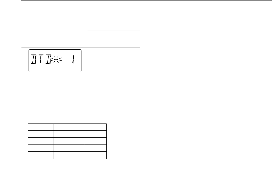
47
10 DTMF MEMORY ENCODER
■DTMF speed
The rate at which DTMF memories send individual DTMF
characters can be set to accommodate operating needs.
qPush [PWR] for 1 sec. to turn power OFF.
wWhile pushing [SET(LOCK)], push [PWR] for 1 sec. to turn
power ON and enter initial set mode.
ePush [SET(LOCK)] or [MW(S.MW)] several times to select
the “DTD” display as shown above.
rRotate the tuning dial to select the desired speed as
shown in the table below.
tPush [PWR] to exit initial set mode.
cps=characters/sec
The display shows the fast-
est DTMF speed is select-
ed.
USING
INITIAL SET MODE
DISPLAY INTERVAL SPEED
DTD-- 1 100 msec. 5.0 cps
DTD-- 2 200 msec. 2.5 cps
DTD-- 3 300 msec. 1.6 cps
DTD-- 5 500 msec. 1.0 cps
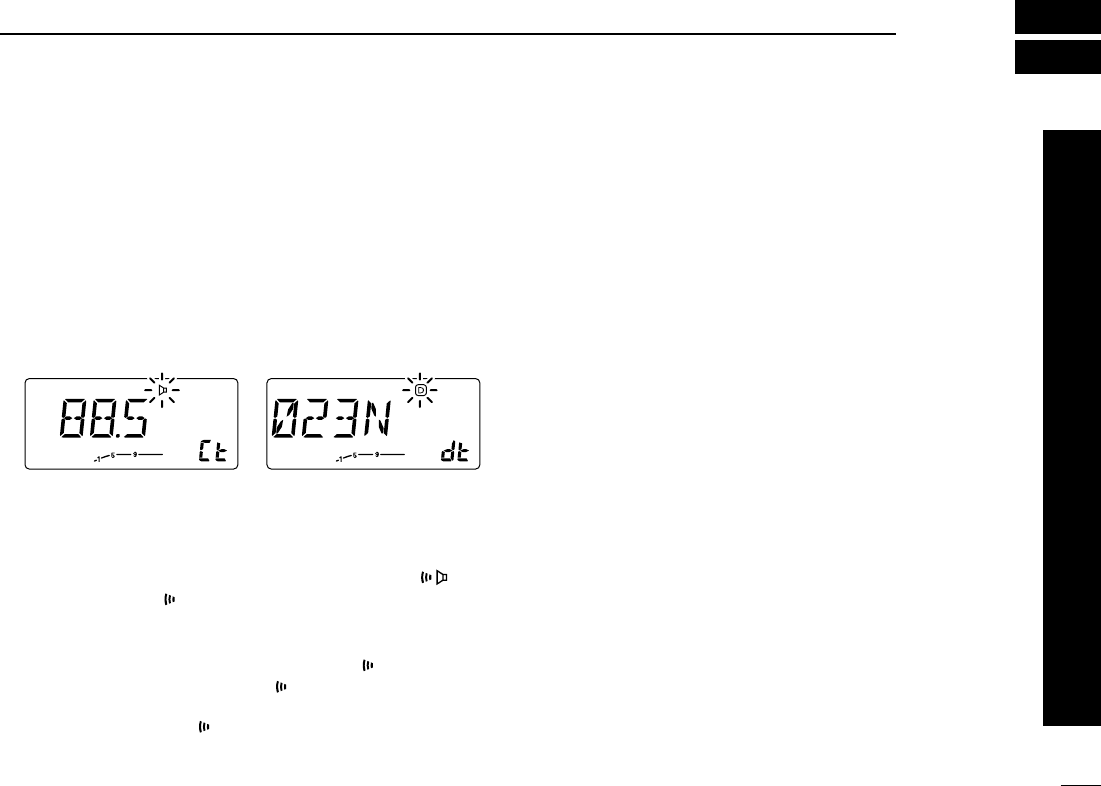
48
11
POCKET BEEP AND TONE SQUELCH
1
2
3
4
5
6
7
8
9
10
11
12
13
14
15
16
17
18
19
20
21
■Pocket beep operation
This function uses subaudible tones for calling and can be
used as a “common pager” to inform you that someone has
called while you were away from the transceiver.
DWaiting for a call from a specific station
qSet the operating frequency.
wPush [SET(LOCK)] to enter set mode.
ePush [SET(LOCK)] or [MW(S.MW)] several times until “Ct”
for tone squelch or “dt” for DTCS squelch appears.
rRotate the tuning dial to select the desired tone squelch
frequency or DTCS code and porality.
tPush [V/MHz(SCAN] to exit set mode.
yPush [TONE(T-SCAN)] several times to indicate “” for
tone squelch or “D” for DTCS squelch in the function
display.
uWhen a signal with the matched tone is received, the
transceiver emits beep tones and flashes “”.
•Beep tones sound for 30 sec and “” flashes. To stop the beeps
and flashing manually, push any key. When the beep tones are
not stopped manually, “” continues flashing until step i.
iPush [PTT] to answer.
oPush [TONE(T-SCAN)] several times to cancel the func-
tion.
zSet the operating frequency.
xProgram the CTCSS tone frequency or DTCS code in set
mode.
•See p. 18 for programming details.
cPush [FUNC] then [iT SQLS] to turn the pocket beep
ON.
vWhen a signal with the matched tone is received, the
transceiver emits beep tones for 30 sec. and flashes
“S”.
bPush [PTT] to answer or push [clr A(MW)] to stop the
beeps and flashing.
•Tone squelch is automatically selected.
•Pushing [FUNC] then [oTSQL] also selects the
tone squelch.
nTo cancel the function, push [FUNC] then [GT-OFF].
DCalling a waiting station using pocket beep
A subaudible tone matched with the station’s CTCSS tone fre-
quency or 3-digit DTCS code with polarity is necessary. Use
the tone squelch on the next page or a subaudible tone en-
coder (pgs. 00, 00)
■Tone squelch operation
The tone squelch opens only when receiving a signal with the
same pre-programmed subaudible tone.
Tone squelch frqueency setting DTCS code setting

49
11 POCKET BEEP AND TONE SQUELCH
qSet the operating frequency.
wProgram the CTCSS tone frequency or DTCS code in set
mode.
•See p. 18 for programming details.
ePush [TONE(T-SCAN)] several times. “T SQL” appears in
the function display.
rWhen a signal with the matched tone is received, the
squelch opens and the signal can be heard.
•When the received signal includes an unmatched tone, the
squelch does not open. However, the S/RF indicator shows the
received signal strength.
•To open the squelch manually, push [MONI(ANM)].
tOperate the transceiver in the normal way (push [PTT] to
transmit; release [PTT] to receive).
yTo cancel the tone squelch, push [TONE(T-SCAN)].
•“T SQL” disappears from the function display.
zSet the operating frequency.
xProgram the CTCSS tone frequency or DTCS code in set
mode.
•See p. 18 for programming details.
cPush [FUNC] then [oT SQL] to turn the tone squelch ON.
vWhen a signal with the matched tone is received, the
squelch opens and the signal can be heard.
•When the received signal includes an incorrect tone,
the squelch does not open. However, the S/RF indi-
cator shows the received signal strength.
•To open the squelch manually, push [qMONI].
bOperate the transceiver in the normal way (push [PTT] to
transmit; release [PTT] to receive.
nTo cancel the tone squelch, push [FUNC] then [GT-OFF].
■Tone scan
By monitoring a signal that is being operated with pocket
beep or tone squelch function, you can determine the tone
frequency necessary to open a squelch.
qSet the channel to be checked for a tone frequency.
wPush [(TONE)T-SCAN] for 1 sec. to start the tone scan.
•To change the scanning direction, rotate the tuning dial.
eWhen the CTCSS tone frequency or 3-digit DTCS code is
matched, the squelch opens and the tone frequency is
temporarily programmed into the selected mode such as
memory or call channel.
•The tone scan pauses when a CTCSS tone frequency or 3-digit
DTCS code is detected.
•The decoded CTCSS tone frequency or 3-digit DTCS code is
used for the tone encoder or tone encoder/decoder depending
on the tone squelch ON/OFF setting.
rPush [V/MHz(SCAN)] to stop the scan.
zSet the channel to be checked for a tone frequency.
xPush [F-2] for 1 sec. to start the tone scan.
cWhen the tone frequency is matched, the squelch opens
and the tone frequency is programmed into the selected
mode such as memory or call channel.
vPush [clr A(MW)] to stop the scan.
☞NOTE: The decoded tone frequency is programmed tem-
porarily when a memory or call channel is selected. How-
ever, this will be cleared when overwriting the memory/call
channel.

1-1-32 Kamiminami, Hirano-ku, Osaka 547-0003 Japan
A-6115D-1EX
Printed in Japan
©2001 Icom Inc.