ICOM orporated SB-110 Wireless LAN Access Point User Manual PDF E 1
ICOM Incorporated Wireless LAN Access Point PDF E 1
UserManual.wiki
>
ICOM orporated
>
SB 110 User Manual
Manual
Navigation menu
Upload a User Manual
Namespaces
Wiki Guide
HTML
PDF
Info
Views
User Manual
Discussion / Help
Navigation
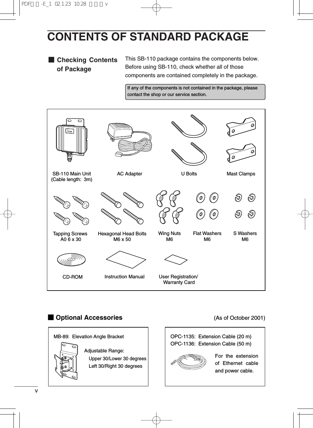
![INTRODUCTIONivINTRODUCTIONNOTES ON HANDLING◎If a connection cable is removed or the connection becomes unstable during an opera-tion, an error may occur. Connect the connectors completely and do not touch the con-nectors during an operation.◎For the handling of PC and any peripheral devices, follow the instructions provided inthe manuals which come with the PC and other peripheral devices.◎SB-110 may cause the signal interference when it is used in your house. When the in-terference occurs, move SB-110 as far as possible away from the affected householdelectric appliance.◎The CD-ROM (excluding Acrobat Reader) which comes with SB-110 is for SB-110 only.Do not use it for any other devices.◎Icom Inc. is not responsible for any interference arisen by incorporating a configurationfile for SB-110 or a firmware update data file, which is available in our home page, intoany device other than SB-110. Moreover, Icom Inc. is not responsible for any interfer-ence arisen by modifying or disassembling SB-110. Furthermore, Icom Inc. is not re-sponsible for any damages, lost profits or third party's claim resulting from any missedcommunication or telephone call due to SB-110's fault, error, malfunction, breakage,data loss or any other external factor such as power failure.◎All copyrights associated with this manual and all intellectual property rights associatedwith the hardware and software of SB-110 are held by Icom Inc.◎Unauthorized diversion of this manual, in part or in whole, is prohibited.◎The content of this manual, the hardware and software associated with SB-110, andthe appearance of SB-110 are all subject to change without notice.The following notational conventions are used in this manual:•The names of utilities, menus, windows, tabs, icons, text boxes, and check boxes areenclosed in square brackets ([ ]).•The names of command buttons within dialog boxes are enclosed in less-than andgreater-than signs (< >).*The description of this manual is based the used of the firmware version 1.00 (see 6-6).*Windows 98 SE represents the Windows 98 Second Edition.Windows Me represents the Windows Millennium Edition.*The contents of windows appearing in this manual may vary depending on theoperating system installed on your computer.Notational ConventionsPDF取説-E_1 02.1.23 10:28 ページiv](https://usermanual.wiki/ICOM-orporated/SB-110/User-Guide-222814-Page-5.png)
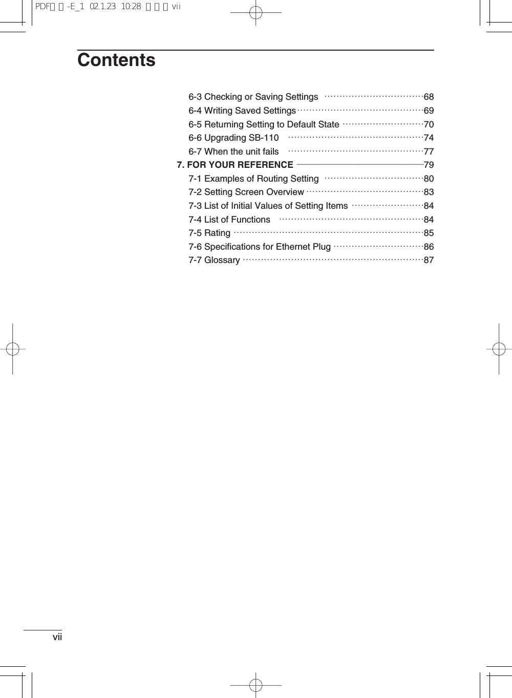
![ContentsviContentsINTRODUCTION ────────────────────iCONTENTS OF STANDARD PACKAGE ─────────v■Checking Contents of Package ……………………………v■Optional Accessories ………………………………………vContents ───────────────────────viSAFETY PRECAUTIONS(Be sure to read)───────viii1. BEFORE INSTALLATION ──────────────11-1.Name and Function of Component ………………………21-2.Radio Communication Function …………………………31-3.Using in Building Communication Mode …………………31-4.Using in Access Point Mode ………………………………41-5.Using Roaming Function …………………………………51-6.Notes on Installation ………………………………………72. INSTALLATION AND CONNECTION ─────────92-1.Installing on Mast …………………………………………102-2.Fixing on Wall ……………………………………………112-3.How to Connect……………………………………………122-4.Before Connecting Existing LAN ………………………133. SETTING YOUR PC ────────────────153-1.Connecting in Building Communication Mode …………163-2.Connecting through Wireless Access Point ……………223-3.Preparing WWW Browser ………………………………283-4.Checking IP Assigned Address …………………………294. SETTING SB-110──────────────────334-1.Turning on SB-110 and PC ………………………………344-2.Showing Setting Screen …………………………………354-3.Changing Wireless Communication Mode ……………364-4.Stopping DHCP Server …………………………………374-5.Changing IP Address Of SB-110 ………………………384-6.Changing Automatic Assignment Start IP Address ……395. SETTING SCREEN ─────────────────415-1 [Wireless LAN settings] Screen …………………………425-2 [Detail settings] Screen …………………………………455-3 [IP address] Screen ………………………………………535-4 [Routing function] Screen ………………………………595-5 [Administration] Screen …………………………………626. MAINTENANCE ──────────────────656-1 CD-ROM of SB-110 ………………………………………666-2 Restricting Access to Setting Screen……………………67…………………………………………Continue to the next page.PDF取説-E_1 02.1.23 10:28 ページvi](https://usermanual.wiki/ICOM-orporated/SB-110/User-Guide-222814-Page-7.png)
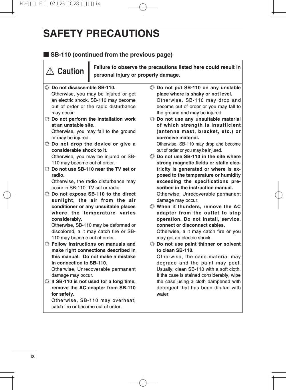
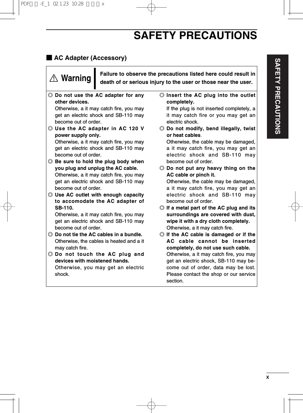
![SAFETY PRECAUTIONSviiiSAFETY PRECAUTIONS¡These precautions are intended to ensure that SB-110 is operated safely and cor-rectly. Follow these instructions to avoid property damage and prevent personalinjury to yourself (user) or others in the vicinity.¡Before reading the rest of this manual, read and understand the precautionslisted under [ RWarning ] and [ RCaution ] below.¡After reading this manual, store it in a convenient place for future review.Be sure to read these precautions in order to use SB-110 safely.■SB-110Failure to observe the precautions listed here could result indeath of or serious injury to the user or those near the user.◎Do not touch SB-110 with moistenedhands.Otherwise, you may get an electric shock.◎Do not put any heavy thing on theconnecting cable or pinch it.Otherwise, the cable may be damaged,a it may catch fire, you may get anelectric shock and SB-110 maybecome out of order.◎Do not machine, bend by force, twist,pull or heat the connecting cable.Otherwise, the cable may be damaged,a it may catch fire, you may get anelectric shock and SB-110 maybecome out of order.◎SB-110 is adjusted fully. Do notdisassemble or remodel SB-110. Donot repair SB-110 by yourself.Otherwise, a it may catch fire, you mayget an electric shock and SB-110 maybecome out of order.◎Discontinue use immediately if SB-110 emits smoke, an abnormal odor,or an abnormal noise.Otherwise, a it may catch fire, you mayget an electric shock and SB-110 maybecome out of order. Remove the ACadapter and all the cables from SB-110immediately. Confirm the smoke disap-pears and contact the shop or our ser-vice section.◎Do not install SB-110 at an unsuitableplace where the structural strength isinsufficient.Otherwise, SB-110 may drop andbecome out of order due to vibration orwind and people may be injured.◎Do not install SB-110 at any crowdedarea.Otherwise, people may contact SB-110,may fall to the ground or may be injured.◎Do not install SB-110 near the powerline or distribution line.Otherwise, SB-110 cable may contactthe power line or distribution line, maybe short-circuited or heated. Moreover,people may get an electric shock or a itmay catch fire.◎Do not touch SB-110, antenna cableor power cable when it thunders.Otherwise, you may get an electric shock.◎Use the specified articles andaccessories only.Otherwise, a it may catch fire, you mayget an electric shock and SB-110 maybecome out of order.◎Be sure to connect the power supplyto the DC connector only.Otherwise, a it may catch fire, you mayget an electric shock and SB-110 maybecome out of order.RWarningPDF取説-E_1 02.1.23 10:28 ページviii](https://usermanual.wiki/ICOM-orporated/SB-110/User-Guide-222814-Page-9.png)

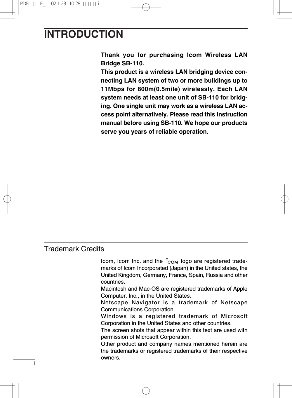
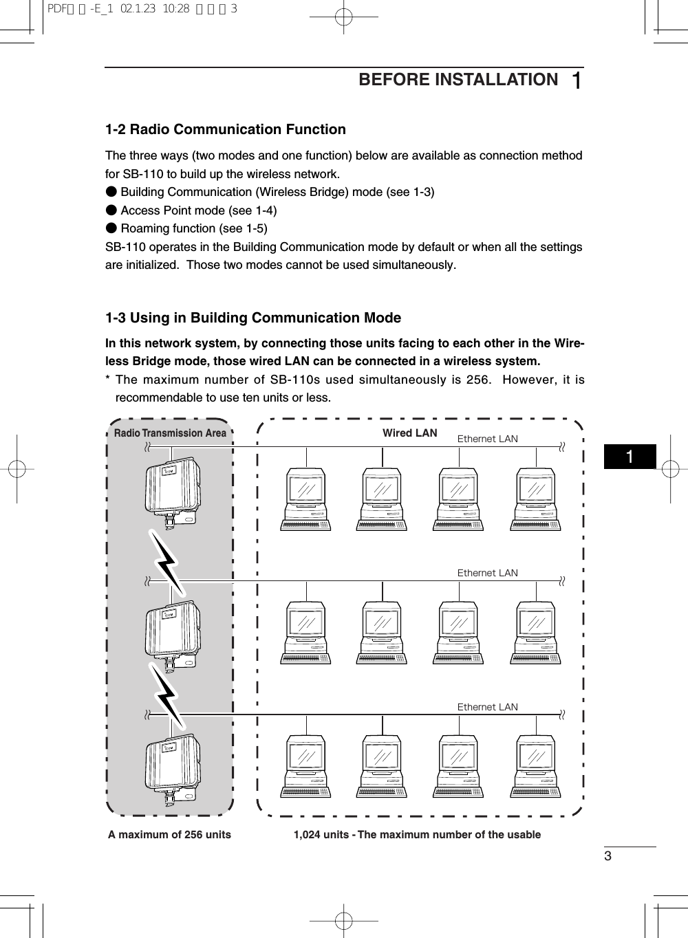
![2BEFORE INSTALLATION11-1 Name and Function of ComponentqEthernet cable/DC cableUsed to connect SB-110 to the wired LAN (Hub).This cable is for straight connection.Connect the AC adapter, which comes with SB-110, to the DC cable.w[ ] (Red) indicatorTurns on when the connection to SB-110 has been established. The indicator turns off when:¡All the radio devices is in no-communication state for one or two minutes.¡All the radio devices is out of radio transmission area for one or two minutes.e[PWR] (Green) indicatorTurns on when SB-110 turns on.Blinks alternately with the [MODE] indicator in the [UTILITY] mode operation.Blinks simultaneously with the [MODE] indicator in the [INITIALIZATION] mode operation.r<MODE> buttonUse for an operation in the [UTILITY] mode and [INITIALIZATION] mode.t[MODE] (Green) indicatorBlinks in the [UTILITY] mode and [INITIALIZATION] mode.Blinks alternately with the [PWR] indicator in the [UTILITY] mode operation.Blinks simultaneously with the [PWR] indicator in the [INITIALIZATION] mode operation.y[LAN] (Red) indicatorTurns on when the connection to LAN has been established normally.Turns off when the Ethernet cable is not connected.Blinks when data is communicated.※A plate to fix SB-110 cable. If you connect a commercial ground cable, fix it with the screws forthis plate.PWR MODEMODELAN※qwertyPDF取説-E_1 02.1.23 10:28 ページ2](https://usermanual.wiki/ICOM-orporated/SB-110/User-Guide-222814-Page-14.png)
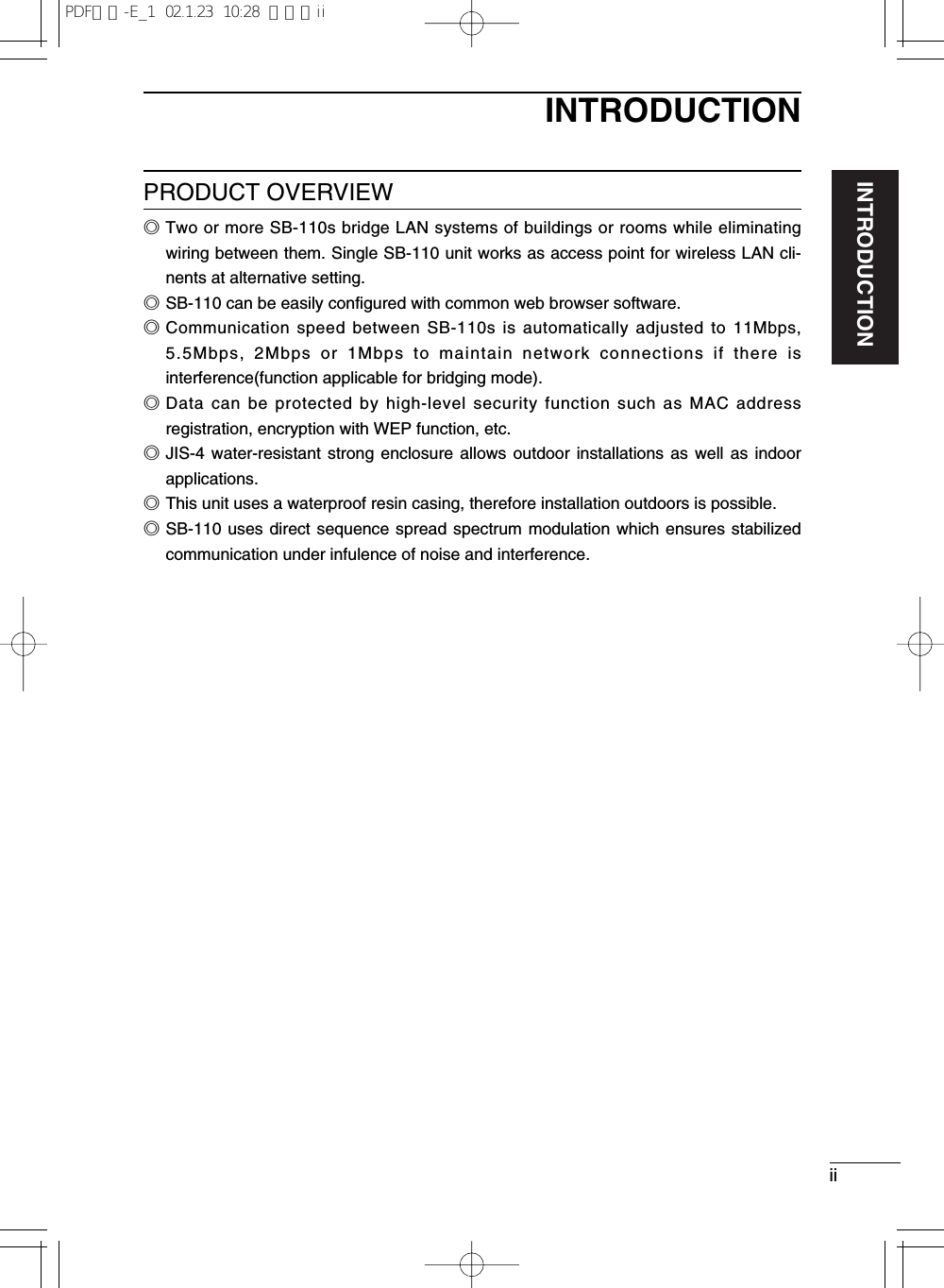
![4BEFORE INSTALLATION11-4 Using in Access Point ModeIn this wireless LAN system, wireless terminals are connected to each other throughSB-110 by wireless or a terminal connected to SB-110 through Ethernet is connectedto a wireless terminal through SB-110 by wireless.If you use SB-110 as an access point, you need to change the default setting (☞see 4-3)using a PC connected to SB-110 through a hub on Ethernet LAN.* The maximum number of SB-110s used simultaneously is 256. However, it isrecommendable to use ten units or less.■Notes on Use of Access Point Mode◎The Building Communication mode is disabled whenthe Access Point mode (☞see 4-3) is enabled.◎Any terminal connected to SB-110 by wireless mustbe equipped with our 11 Mbps wireless LAN card.◎If [ESS ID] or [WEP] (☞see page 27) specified in awireless terminal is different from that of SB-110, anycommunication to such wireless terminal isunavailable.Wireless LAN CardWireless LANA maximum of 256 units are acceptable.Wired LANRadio TransmissionAreaEthernet LANEthernet LANPDF取説-E_1 02.1.23 10:28 ページ4](https://usermanual.wiki/ICOM-orporated/SB-110/User-Guide-222814-Page-16.png)
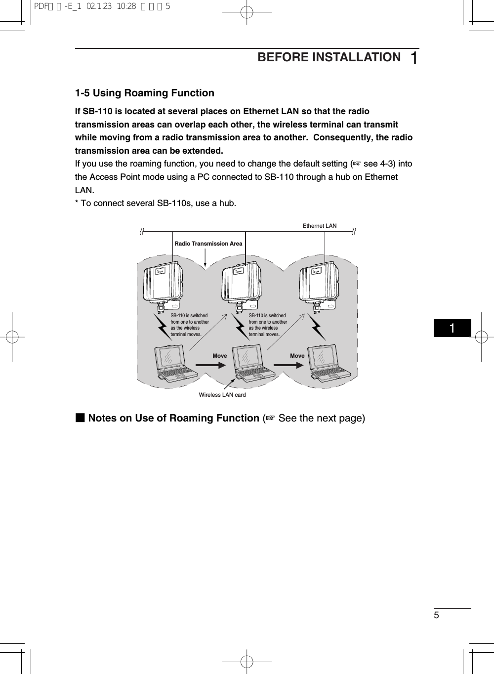
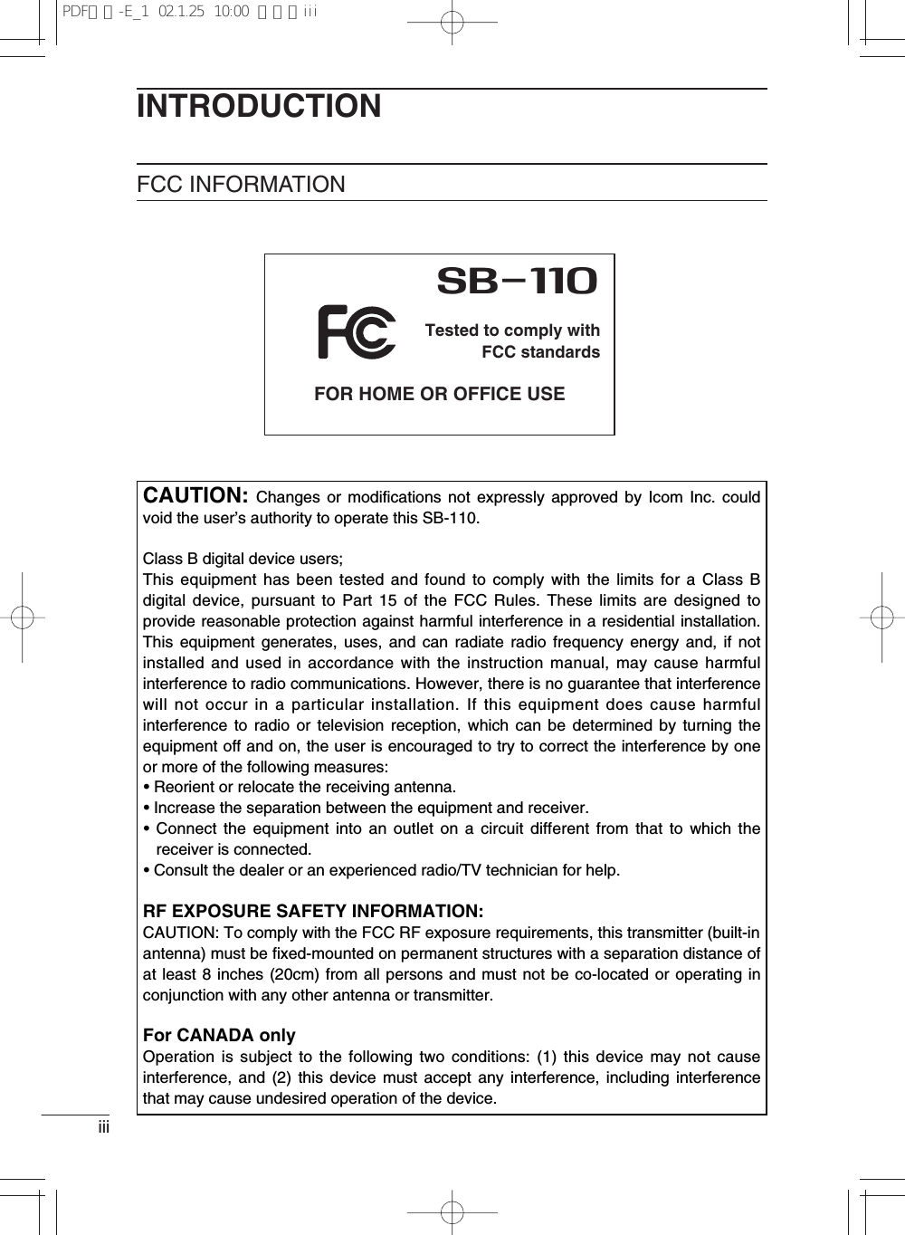
![6BEFORE INSTALLATION11-5 Using Roaming Function (continued from the previous page)■Notes on Use of Roaming Function◎The roaming function is enabled in the Access Point mode and, therefore, this functioncannot be used in the Building Communication mode.◎Any terminal connected to SB-110 by wireless must be equipped with our 11 Mbpswireless LAN card.◎In the radio transmission area where a wireless terminal moves around, [ESS ID] (☞see 5-1) and [WEP] (☞see 5-2) of the wireless terminal must be the same as those ofSB-110 used in the roaming function. If [ESS ID] or [WEP] specified in the wirelessterminal is different from that of SB-110, any communication to such wireless terminal isunavailable.◎Any wireless LAN terminal operates as a network group which is the same as that ofwired LAN terminal, including the roaming area. Therefore, do not used the roamingfunction together with the Routing mode (☞see 5-3).Otherwise, the communication becomes unavailable due to invalid network address.◎To avoid radio interference, when any channel is changed, keep a sufficient distanceequivalent to four channels or more between the channel to be changed and the otherparty's radio access point channel. Otherwise, as shown below, the radio interferencemay occur because a part of frequency bands overlap each other. For example, ifChannel 1, Channel 6 and Channel 11 are specified, no radio interference occurs.2400 2410 2420 2430 2440 2450Frequency (MHz)2460 2470 2480Channel 1Channel 2Channel 3Channel 4Channel 5Channel 6Channel 7Channel 8Channel 9Channel 11Channel 10PDF取説-E_1 02.1.23 10:28 ページ6](https://usermanual.wiki/ICOM-orporated/SB-110/User-Guide-222814-Page-18.png)

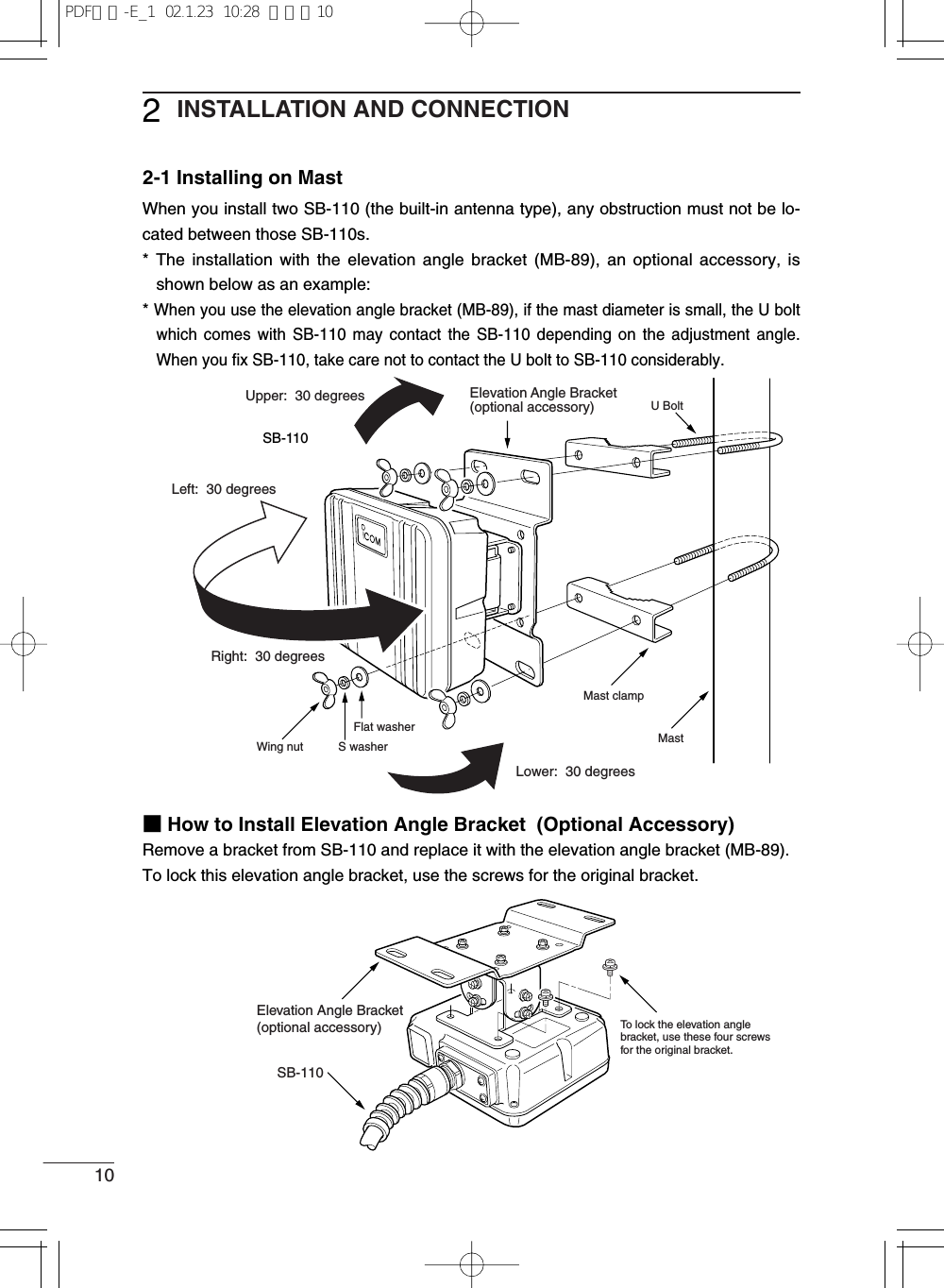
![11INSTALLATION AND CONNECTION 222-2 Fixing on WallTo fix SB-110 on the wall, use the tapping screws or hexagonal head bolts which come with SB-110.[Fixing with Hexagonal Head Bolt]Hexagonal Head Bolt M6 x 50SB-110Wing NutFlat WasherS WasherWall Surface[Fixing with Tapping Screw]Tapping Screw (A0) M6 x 30SB-110External WallPDF取説-E_1 02.1.23 10:28 ページ11](https://usermanual.wiki/ICOM-orporated/SB-110/User-Guide-222814-Page-23.png)
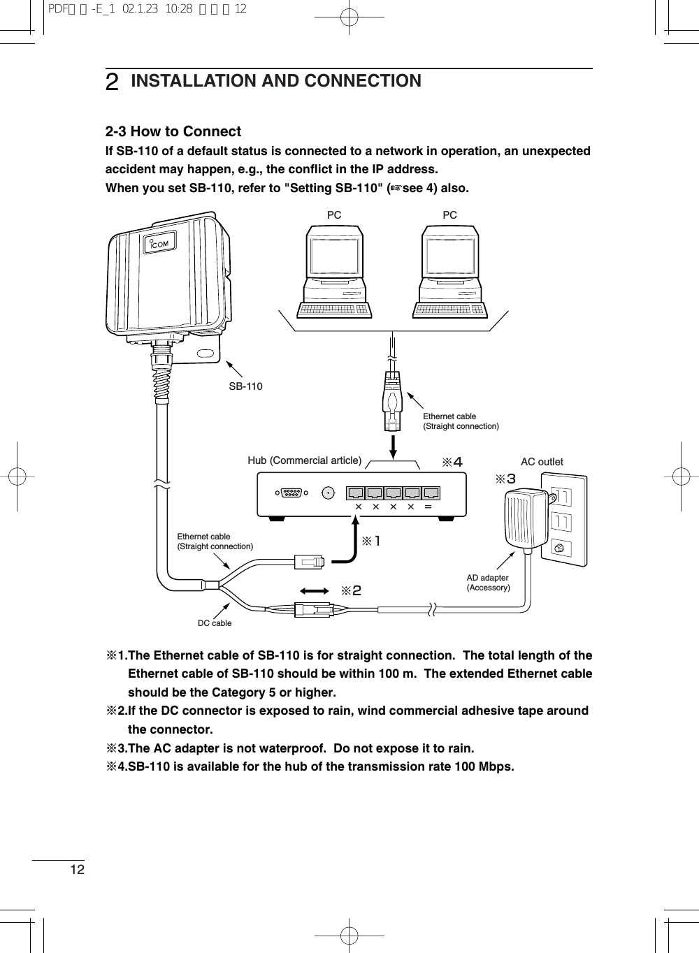
![13INSTALLATION AND CONNECTION 222-4 Before Connecting Existing LANWhen you connect SB-110 to an existing LAN, you need to assign the IP address to SB-110 according to the IP address assignment system specified in the LAN in advance.* To change the IP address of SB-110, refer to "How to Change IP Address" (☞see 4-5).[Connection to environment that fixed IP address is assigned]Assign an available IP address to SB-110.[Connection to environment that the DHCP server function is used]Change the SB-110 setting to disable the DHCP server function and assign an IP addresswhich is not assigned automatically.■Checking Network StatusWhen a network is built on an existing LAN, please note the points below:[IP address of each PC on LAN]For TCP/IP, if an IP address of a network device (e.g., PC) on the network is the same asthat of SB-110, any communication cannot be made between SB-110 and such networkdevice. Moreover, the entire network may be affected.If any network device on an existing network has the IP address [192.168.0.1], you need tochange the default IP address of SB-110 (☞see 4-5) before connecting SB-110 to suchexisting network.When you assign an IP address to network devices statically, take care not to assign thesame IP address to those network devices. Even when you assign the IP address dy-namically, you need to change the setting so that the IP addresses assigned by the DHCPserver function are different from the IP address of SB-110. Please note that the broadcastaddress cannot be assigned to any device on the network.■Setting IP AddressWhen the IP address of any other network which you want to connect is the same as thatof SB-110, change the IP address into one specified in the LAN.* For how to set it, refer to "How to Change IP Address" (☞see 4-5).■Connecting to Existing LANConnect to the LAN referring to "How to Connect" (☞see 2-3).PDF取説-E_1 02.1.23 10:28 ページ13](https://usermanual.wiki/ICOM-orporated/SB-110/User-Guide-222814-Page-25.png)

![CHAPTER 3SETTING YOUR PC3-1. Connecting in Building Communication Mode……………………………………16■Connecting to Ethernet Cable of SB-110 ……………………………………16■Setting TCP/IP Protocol[Windows Me] ……………………………………………………………………16[Windows 2000] …………………………………………………………………19[Mac OS] …………………………………………………………………………213-2. Connecting through Wireless Access Point ………………………………………22■Preparing Wireless LAN Card …………………………………………………22■Setting TCP/IP Protocol[Windows Me] ……………………………………………………………………22[Windows 2000] …………………………………………………………………25■Setting Wireless LAN Card ……………………………………………………273-3. Preparing WWW Browser …………………………………………………………283-4. Checking IP Assigned Address ……………………………………………………29[Windows Me] ……………………………………………………………………29[Windows 2000] …………………………………………………………………30[Mac OS] …………………………………………………………………………31This chapter describes how to set a PC which communicates with SB-110.Read an applicable section as necessary.](https://usermanual.wiki/ICOM-orporated/SB-110/User-Guide-222814-Page-27.png)
![16SETTING YOUR PC33-1 Connecting in Building Communication ModeThis section describes the setting to connect your PC to SB-110 through a hub.■Connecting to Ethernet Cable of SB-110Referring to the description of 2-3, connect the Ethernet cable of SB-110 to your PCthrough the hub. If your PC has no Ethernet port, you need to mount any commercial Eth-ernet card to the PC. Mount it to your PC according to the instruction manuals which comewith the PC and Ethernet card.■Setting TCP/IP ProtocolYou need to install a network protocol module (driver) called "TCP/IP" in every PC whichcommunicates with SB-110. Install the driver referring to the instruction manual whichcomes with your Ethernet card.[Windows Me]1. Select [Start] →[Setting (S)] →[Control Panel (C)] →[Network] icon.2. Check that [TCP/IP →Name of your Ethernet card] and [Microsoft Network Client] aredisplayed in the [Network] screen. If those are not displayed, TCP/IP installation mayfail. Check the installation referring to the instruction manual which comes with yourEthernet card.Step 1 Connecting Your PC to SB-110 ━━━━━━━12, 16Step 2 Setting TCP/IP ━━━━━━━━━━━━━━━━16Step 3 Preparing WWW Browser ━━━━━━━━━━━28Step 4 Checking IP Address Assigned by SB-110 ━━━29PDF取説-E_1 02.1.23 10:28 ページ16](https://usermanual.wiki/ICOM-orporated/SB-110/User-Guide-222814-Page-28.png)
![17SETTING YOUR PC 333. Click [TCP/IP] and then [Properties (R)].CheckClick2.Click1.[Windows Me] (continued from the previous page)PDF取説-E_1 02.1.23 10:28 ページ17](https://usermanual.wiki/ICOM-orporated/SB-110/User-Guide-222814-Page-29.png)
![18SETTING YOUR PC33-1 Connecting in Building Communication Mode■Setting TCP/IP Protocol [Windows Me] (continued from the previous page)4. Click the [Obtain an IP address automatically (O)] radio button and then [OK].Click1.5. When you are prompted to restart your PC, click [Yes]. The specified setting is en-abled when the PC has been restarted.Click2.ClickPDF取説-E_1 02.1.23 10:28 ページ18](https://usermanual.wiki/ICOM-orporated/SB-110/User-Guide-222814-Page-30.png)
![19SETTING YOUR PC 33■Setting TCP/IP Protocol (continued from the previous page)[Windows 2000]1. Start your PC.¡The Windows 2000 log-on screen is shown.2. Log on as the Administrator.3. When the Windows 2000 desktop has been shown, select [Start] →[Setting (S)] →[Network and Dial-up Connections (N)] →[Local Area Connection] icon which showsyour Ethernet card name.4. Click [Properties (P)].Double-clickClickPDF取説-E_1 02.1.23 10:28 ページ19](https://usermanual.wiki/ICOM-orporated/SB-110/User-Guide-222814-Page-31.png)
![20SETTING YOUR PC33-1 Connecting in Building Communication Mode■Setting TCP/IP Protocol [Windows 2000] (continued from the previous page)5. If [Internet Protocol (TCP/IP)] is shown, click [Internet Protocol (TCP/IP)] and then [Prop-erties (R)].Click1.Click2.Check1.6. Check that [Obtain an IP address automatically (O)] is selected and click [OK] to enablethe specified setting.Click2.PDF取説-E_1 02.1.23 10:28 ページ20](https://usermanual.wiki/ICOM-orporated/SB-110/User-Guide-222814-Page-32.png)
![21SETTING YOUR PC 33[Mac OS]1. Start your PC.2. When your PC has started up, select [Apple Menu] →[Control Panel] →[TCP/IP].3. Specify "Ethernet" as [Connect to] and "Using DHCP Server" as [Configure].4. Click the Close Box on the title bar.¡The screen is closed and the setting screen is saved.Select1.Click3.Select2.PDF取説-E_1 02.1.23 10:28 ページ21](https://usermanual.wiki/ICOM-orporated/SB-110/User-Guide-222814-Page-33.png)
![22SETTING YOUR PC33-2 Connecting through Wireless Access PointStep 1 Preparing Wireless LAN Card ━━━━━━━━━22This section describes the setting to connect to SB-110 through a wireless access point.The available operating system is Windows 98, Windows 98SE, Windows Me and Win-dows 2000.Step 2 Setting TCP/IP━━━━━━━━━━━━━━━━━22Step 3 Setting Wireless LAN Card ━━━━━━━━━━━27Step 4 Preparing WWW Browser ━━━━━━━━━━━28■Preparing Wireless LAN CardIf SB-110 is set to the Access Point mode (☞4-3), mount any wireless LAN card specifiedby us to your PC which can be connected to SB-110 by wireless. If the PC has no PCM-CIA slot, you need to mount out wireless LAN card adapter to the PC. Mount it accordingto the instruction manual which comes with the wireless LAN card adapter* If the PC has the USB port only, use our wireless LAN unit (SU-11) to communicate withSB-110 by wireless.■Setting TCP/IP ProtocolYou need to install a network protocol module (driver) called "TCP/IP" in every PC whichcommunicates with SB-110. Install the driver referring to the instruction manual of yourwireless LAN card.[Windows Me]1. Select [Start] →[Setting (S)] →[Control Panel (C)] →[Network] icon.2. Check that [TCP/IP →Name of your wireless LAN card] and [Microsoft Network Client]are displayed in the [Network] screen. If those are not displayed, TCP/IP installationmay fail. Check the installation referring to the instruction manual of your wireless LANcard.Step 5 Checking IP Address Assigned by SB-110 ━━━29PDF取説-E_1 02.1.23 10:28 ページ22](https://usermanual.wiki/ICOM-orporated/SB-110/User-Guide-222814-Page-34.png)
![23SETTING YOUR PC 333. Click [TCP/IP] and then [Properties (R)].CheckClick2.Click1.PDF取説-E_1 02.1.23 10:28 ページ23](https://usermanual.wiki/ICOM-orporated/SB-110/User-Guide-222814-Page-35.png)
![24SETTING YOUR PC33-2 Connecting through Wireless Access Point■Setting TCP/IP Protocol [Windows Me] (continued from the previous page)4. Click the [Obtain an IP address automatically (O)] radio button and then [OK].5. When you are prompted to restart your PC, click [Yes]. The specified setting is en-abled when the PC has been restarted.Click1.Click2.ClickPDF取説-E_1 02.1.23 10:28 ページ24](https://usermanual.wiki/ICOM-orporated/SB-110/User-Guide-222814-Page-36.png)
![25SETTING YOUR PC 33■Setting TCP/IP Protocol (continued from the previous page)[Windows 2000]1. Start your PC.¡The Windows 2000 log-on screen is shown.2. Log on as the Administrator.3. When the Windows 2000 desktop has been shown, select [Start] →[Setting (S)] →[Network and Dial-up Connections (N)] →[Local Area Connection] (which shows yourEthernet card name).4. Click [Local Area Connection] which shows your wireless LAN card connecting SB-110.Double-clickClickPDF取説-E_1 02.1.23 10:28 ページ25](https://usermanual.wiki/ICOM-orporated/SB-110/User-Guide-222814-Page-37.png)
![26SETTING YOUR PC33-2 Connecting through Wireless Access Point■Setting TCP/IP Protocol [Windows 2000] (continued from the previous page)5. If [Internet Protocol (TCP/IP)] is shown, click [Internet Protocol (TCP/IP)] and then [Prop-erties (R)].6. Check that [Obtain an IP address automatically (O)] is selected and click [OK] to enablethe specified setting.Click1.Click2.Click2.Check1.PDF取説-E_1 02.1.23 10:28 ページ26](https://usermanual.wiki/ICOM-orporated/SB-110/User-Guide-222814-Page-38.png)
![27SETTING YOUR PC 333-2 Connecting through Wireless Access Point■Setting Wireless LAN CardThe values of the setting items below of your PC (PC/AT compatible machine) to be con-nected through the wireless LAN must be the same as those of SB-110. Change the setvalues of the PC according to the default setting of SB-110. For how to change the set val-ues of PC, refer to the instruction manual of your wireless LAN card.[Network Mode]Communication is made to a repeater called "Wireless Access Point". Set your PC in theInfrastructure mode. The wireless communication mode of SB-110 needs to be changed(☞see 4-3).[ESS ID]PCs with the same name are identified as the same work group on the wireless network.Change the PC setting into "LG". The default setting of SB-110 is "LG".[Communication Channel]This is disabled for the communication in the Infrastructure mode. The wireless commu-nication is made according to the communication channel (☞see 5-2) set in SB-110.[WEP Function]When communication is made through a wireless LAN, the communication data is en-crypted. Disable the WEP security of your PC. The default setting of SB-110 is "Not UseWEP Key".【RRemarks】¡Wireless communication to Macintosh is unavailable.¡Use a suitable wireless LAN card which supports SB-110. Otherwise, no communication can be made.¡Write down the value set in SB-110 exactly and be sure to set such value in all the devices to be com-municated by wireless.¡While you are changing [Communication Channel], [ESS ID] or [WEP] of SB-110, communication from aPC connected to SB-110 through a wireless LAN becomes unavailable temporarily. The connection isready again when the setting of every device becomes the same.¡When the WEP function is not used, a third party may connect from the outside. You may encounter arisk, e.g., unauthorized access, wiretapping, interference, data loss or memory crash. To avoid suchrisk, it is recommendable to use the WEP function without fail.¡To communicate with SB-110 by wireless through the WEP function, our wireless LAN card must beused.¡When an operation has become unstable during the wireless communication, move SB-110 or the PC orchange the direction of them.¡When many PCs access the wireless LAN of SB-110 simultaneously, the communication speed maydecrease considerably. The maximum number of wireless terminals used simultaneously is 256. How-ever, it is recommendable to use ten terminals or less.PDF取説-E_1 02.1.23 10:28 ページ27](https://usermanual.wiki/ICOM-orporated/SB-110/User-Guide-222814-Page-39.png)
![28SETTING YOUR PC33-3 Preparing WWW BrowserTo set SB-110 through a WWW browser, Microsoft Internet Explorer 4.0 or later orNetscape Navigator 4.0 or later must be used. When you access the internet through aPC, whether it is connected by wireless or not, check the "proxy server function" is dis-abled in the browser setting.If you want to use the proxy server, do not take SB-110 as an object of the proxy server ac-cording to the procedure below.[Microsoft Internet Explorer 5.0]The procedure to exclude SB-110 from the scope of the proxy server is as follows:1. Select [Internet Options (O)] in the [Tool (T)] menu.2. Click the [Connections] tab and then [LAN Settings (L)].3. Check the [Use a proxy server (X)] check box and click [Advanced (C)].4. Enter an address of the proxy server of your provider in the [HTTP (H)] text box in the[Servers] field.5. Enter the IP address of SB-110 in the [Do not use proxy server for addresses beginningwith (N):] text box in the [Exceptions] field. (Example: 192.168.0.1)[Netscape 6.0]The procedure to exclude SB-110 from the scope of the proxy server is as follows:1. Select [Preferences (E)] in the [Edit (E)] menu.2. Click [Advanced] and then [Proxies] in the [Category:] field of the [Preferences] dialogbox.3. Check the [Manual proxy configuration] radio button.4. Enter an address of the proxy server of your provider in the [HTTP (H)] text box.5. Enter the IP address of SB-110 in the [Do not use proxy server for domains beginningwith (N):] text box. (Example: 192.168.0.1)PDF取説-E_1 02.1.23 10:28 ページ28](https://usermanual.wiki/ICOM-orporated/SB-110/User-Guide-222814-Page-40.png)
![29SETTING YOUR PC 333-4 Checking IP Assigned AddressThis section describes how to check an IP address assigned to a PC automatically by theDHCP server function. Check according to the instruction per operating system below.[Windows Me]Check an IP address with a program called "winipcfg.exe" contained in the Windows folderof the installed operating system.<How to check>1. Select [Start] →[Run (R)].2. Type "winipcfg" in the [RUN] dialog box (falf size) and press the [Enter] key.3. Click ▼in the text box and select a name of your Ethernet card or wireless LAN card.¡When any IP address has been assigned to your PC by the DHCP server, it is dis-played in the [IP Address] field.【If automatic assignment fails】If the network section of IP address of PC is different from that (192.168.0.1) of IP address of SB-110, theautomatic IP address assignment may fail. Check the TCP/IP protocol settings of your Ethernet cared orwireless LAN card and the cable connection and restart the PC.When the PC has restarted, check the IP address again according to the procedure above.<Items displayed on the screen>◎Adapter Address: MAC address of Ethernet card or wireless LAN card.◎IP Address: IP address of PC.◎Subnet Mask: Subnet mask of PC◎Default Gateway: IP address of network device specified as the default gateway.Select1.Check2.PDF取説-E_1 02.1.23 10:28 ページ29](https://usermanual.wiki/ICOM-orporated/SB-110/User-Guide-222814-Page-41.png)
![30SETTING YOUR PC33-5 Checking IP Assigned Address (continued from the previous page)[Windows 2000]Execute "ipconfig" in the Command Prompt screen.<How to check>1. Select [Start] →[Programs (P)] →[Accessories] →[Command Prompt].2. Type "ipconfig" in the Command Prompt screen and press the [Enter] key.* For the details of the command line options, refer to the description shown by typing"ipconfig /?".3. The IP address assigned to the PC is displayed on the screen.CheckPDF取説-E_1 02.1.23 10:28 ページ30](https://usermanual.wiki/ICOM-orporated/SB-110/User-Guide-222814-Page-42.png)
![31SETTING YOUR PC 332. To check the MAC address, select [Apple Menu] →[Control Panel] →[AppleTalk].Then, either of the screens below is shown. Select "Ethernet" in the [Connect via:] field.*To show the left screen when the right screens is shown, select [Menu] in the menu bar, [User Mode]and then [Advanced].Check[Mac OS]Even when the PC has started up, the DHCP server does not give the IP address untilcommunication is made actually (i.e., until you access the internet or you access a mailserver). When <Refer to a server> is displayed on each item on the screen shown by theprocedure below, perform the communication once and then check again.* The operation screen or any other details may vary depending on your operating systemversion.<How to check>1. Select [Apple Menu] →[Control Panel] →[TCP/IP].¡If any IP address is assigned to the PC by the DHCP server, it is displayed on the [IPAddress] field.Select1.Check2.PDF取説-E_1 02.1.23 10:28 ページ31](https://usermanual.wiki/ICOM-orporated/SB-110/User-Guide-222814-Page-43.png)
![32SETTING YOUR PC33-5 Checking IP Assigned Address[Mac OS] (continued from the previous page)3. Click [Info].To show the left screen when the right screens is shown, select [File] in the menu bar and then [Get Info].CheckPDF取説-E_1 02.1.23 10:28 ページ32](https://usermanual.wiki/ICOM-orporated/SB-110/User-Guide-222814-Page-44.png)
![34SETTING SB-11044-1 Turning on SB-110 and PCThrough a hub, connect SB-110 to a PC used for setting.[Remarks]◎In the default setting, a wireless terminal cannotconnect to SB-110 through an access point (☞see 4-3).◎When you set SB-110, even if SB-110 is usedfor several PCs on a network, disconnect one ofthose PCs from the network.◎The PC used to set SB-110 should be config-ured according to "Connecting in Building Com-munication Mode" (☞see 3-1). Then, the IPaddress of wired terminal is obtained from SB-110 automatically.1. Turn on SB-110 and the hub.2. Check that the [PWR] (Green) indicator and [LAN] (Red) indicator turn on. If one of orboth of them turns off, check that the device power supply and cables are connectedcorrectly.3. Turn on the PC connected to the hub.4. Check that the IP address is assigned from SB-110 (☞3-4).* When the IP address is not assigned, the SB-110 setting screen cannot be shown.Check the TCP/IP setting, etc. in "Connecting in Building Communication Mode" (☞3-1) again.= × × × ×Wired terminalSB-110192.168.0.1HUBPDF取説-E_1 02.1.23 10:28 ページ34](https://usermanual.wiki/ICOM-orporated/SB-110/User-Guide-222814-Page-46.png)
![35SETTING SB-110 444-2 Showing Setting Screen<How to operate>1. Start a WWW browser.* This WWW browser is Internet Explorer 5.0.2. Specify "http://192.168.0.1" (default setting). This is URL of SB-110.¡The [Wireless LAN Settings] screen is shown.■[Wireless LAN Settings] ScreenSetting ScreenSelection Menu[Set] / [Cancel] / [Set & Reboot] Button■Setting Screen Selection MenuAll the Setting Screen titles are shown. When you click any of the titles, the correspondingscreen is shown.¡Wireless LAN settings (Detail settings)Set the wireless communication mode,WEP and MAC address security.¡IP addressSet the routing mode, IP address of SB-110 and DHCP server.¡Routing functionSet when you define packet routing.¡AdministrationSet the manager ID, SYSLOG functionand operation to upgrade SB-110.¡InitializeSet when you return the configuration SB-110 to a default state.¡SaveOperate when you check the details ofSB-110 setting or when you save suchdetails as a configuration file.¡[Set] / [Cancel] / [Set & Reboot]Register the details of setting in the dis-played menu screen or cancel them.When you restart the system to enablethe details of setting, operate the [Set &Reboot] button.¡Setting Screen Display AreaA screen selected in the Setting ScreenSelection menu is shown.Setting Screen Display AreaPDF取説-E_1 02.1.23 10:28 ページ35](https://usermanual.wiki/ICOM-orporated/SB-110/User-Guide-222814-Page-47.png)
![36SETTING SB-11044-3 Changing Wireless Communication ModeWhen you use SB-110 as an wireless access point, change the setting according to theprocedure below.3.SB-110 restarts and operates in the Access Point mode.4.Prepare a PC to which you want to mount our wireless LAN card.5. This PC must be configured according to thedescription of "Connecting through Wireless Ac-cess Point" (☞see 3-2). When you start thePC, the IP address is obtained from SB-110 au-tomatically.¡The [ ] indicator of SB-110 turns on inred.6. Specify "http://192.168.0.1" (default setting). This is URL of SB-110.¡The [Wireless LAN Settings] screen is shown.Click2.Click1.【Wireless Access Point Mode】If you change the SB-110 setting so that the Routing mode (☞see 5-3)is enabled in ad-vance, URL to show the setting screen of SB-110 which operates in the Wireless Ac-cess Point mode is as follows:¡Wired terminal: http://192.168.0.1 (default setting)¡Wireless terminal: http://192.168.1.1 (default setting)【RRemarks】Wireless communication to Macintosh is unavailable. Before making the wireless connection, turn on SB-110.<How to change>1.Access the SB-110 setting screen according to the procedure described in 4-1 and 4-2.¡The [Wireless LAN Settings] screen is shown.2. Operate as follows:The default value of any other items should not be changed.* ESS ID of SB-110 is set to "LG" (upper case, falf size) as a default value. CheckESS ID of your wireless LAN card before connecting SB-110.Wireless Communication LAN CardWireless terminal SB-110PDF取説-E_1 02.1.23 10:28 ページ36](https://usermanual.wiki/ICOM-orporated/SB-110/User-Guide-222814-Page-48.png)
![37SETTING SB-110 444-4 Stopping DHCP ServerWhen you connect to any existing network which operates with the DHCP server function,you need to stop the DHCP server of SB-110 depending on your network environment.<How to stop>1.Access the SB-110 setting screen according to the procedure described in 4-1 and 4-2.¡The [Wireless LAN Settings] screen is shown.2. Click [IP address] in the left frame.¡The [IP address] screen is shown.3. Click the [No] radio button in the [Use DHCP Server] field in the [DHCP Server] (in theright frame). Then, click [Set & Reboot].¡"Now rebooting" is displayed on the screen and the specified details are enabled.Click3.Click1.Click2.4. Change the IP address of SB-110 and of PC according to the IP address assignmentspecified in an existing network (☞see 4-5) and then restart the system.PDF取説-E_1 02.1.23 10:28 ページ37](https://usermanual.wiki/ICOM-orporated/SB-110/User-Guide-222814-Page-49.png)
![38SETTING SB-11044-5 Changing IP Address Of SB-110If SB-110 is used in the default setting when you connect an existing LAN, the IP addressof SB-110 may be the same as that assigned to an existing network device. This sectiondescribes how to change the IP address of SB-110.*When you change the network section of the IP address, if the DHCP server of SB-110 isenabled, you need to change also the network section of the automatic assignment start IPaddress referring "Changing Automatic Assignment Start IP Address" (☞see 5-9).<How to change.1.Access the SB-110 setting screen according to the procedure described in 4-1 and 4-2.¡The [Wireless LAN Settings] screen is shown.2. Click [IP address] in the left frame.¡The [IP address] screen is shown.3. Change the IP address of SB-110 and click [Set & Reboot].¡"The IP address has been changed. Change the computer setting." is displayed onthe screen.4. If the DHCP server function of SB-110 is enabled, obtain the IP address again using"winipcfg.exe" (☞see 3-4) or restart the PC. If the IP address is assigned to the PCmanually, change the IP address of the network section of such PC according to that ofSB-110【How to Assign IP Address】The IP address consists of two elements, i.e., the network section and host section. For "192.168.0.1"(Class C) which is the default IP address of SB-110, the first part "192.168.0" is the network section and thesecond one "1" is the host section. Any network devices (e.g., PC etc.) which have the same network sec-tion are presumed to be on the same network. Every network device on the same network is identified bythe host section.So, when you assign the IP address, consider the following rules:¡Every network device located on the same network must have the same network section.¡Every network devices be located on the same network must have the unique host section.¡Do not assign any network address (the first position of the host section, "0").¡Do not assign any broadcast address (the last position of the host section, "255").Change2.Click1. Not need to be changedunless routing mode isused.Click3.PDF取説-E_1 02.1.23 10:28 ページ38](https://usermanual.wiki/ICOM-orporated/SB-110/User-Guide-222814-Page-50.png)
![39SETTING SB-110 444-6 Changing Automatic Assignment Start IP AddressIf the network section of the IP address of SB-110 is changed to enable the DHCP serverfunction of SB-110, the network section of the automatic assignment start IP address alsomust be changed. This section describes how to change the automatic assignment start IPaddress.<How to change>1.Access the SB-110 setting screen according to the procedure described in 4-1 and 4-2.¡The [Wireless LAN Settings] screen is shown.2. Click [IP address] in the left frame.¡The [IP address] screen is shown.3. Change the automatic assignment start IP address and click [Set & Reboot].¡"Now rebooting" is displayed on the screen and the specified details are enabled.【DHCP Server Function】If the DHCP server function of SB-110 is enabled (the default setting), the IP address can be obtained fromSB-110 automatically when a PC has been connected to SB-110.When you connect SB-110 to an existing LAN, the IP address assigned by SB-110 must be different fromthe fixed IP address assigned to any existing network device (e.g., PC etc). Moreover, the network sectionmust be the same as that of the IP address of SB-110.【The Number of IP Addresses Assigned Automatically】The number of IP address assigned by SB-110 automatically is 5 to 128. For the default assignment startIP address and subnet mask set value, the maximum number of IP addresses which can be assigned log-ically is 254. However, if you assign 128 addresses or more, those addresses should be assigned to theclients manually.Click1. Not need to be changedunless routing mode isused.Change2.4. If the DHCP server function of SB-110 is enabled, obtain the IP address again using"winipcfg.exe" (☞see 3-4) or restart the PC.Click3.PDF取説-E_1 02.1.23 10:28 ページ39](https://usermanual.wiki/ICOM-orporated/SB-110/User-Guide-222814-Page-51.png)

![CHAPTER 5SETTING SCREEN5-1. [Wireless LAN settings] Screen ……………………………………………………42■Wireless LAN setting ……………………………………………………………42■MAC Address security setting …………………………………………………435-2 [Detail settings] Screen ……………………………………………………………45■Detail settings ……………………………………………………………………45■Custom Security …………………………………………………………………47■Hidden Terminal …………………………………………………………………50■Relation between [Security Level] and [Custom Security] …………………51■[Security Level] Setting …………………………………………………………51■Example of [WEP Key] Setting …………………………………………………525-3 [IP address] Screen …………………………………………………………………53■Routing function …………………………………………………………………53■IP address…………………………………………………………………………54■DHCP Server ……………………………………………………………………55■Static DHCP Server ……………………………………………………………585-4 [Routing function] Screen …………………………………………………………59■RIP …………………………………………………………………………………59■Network Interface List ……………………………………………………………59■IP Routing Information …………………………………………………………60■Static Route ………………………………………………………………………615-5 [Administration] Screen ……………………………………………………………62■Manager ID ………………………………………………………………………62■SYSLOG …………………………………………………………………………63■Use utility (Firmware Update Mode)……………………………………………64This chapter describes every item in the SB-110 setting screen.](https://usermanual.wiki/ICOM-orporated/SB-110/User-Guide-222814-Page-53.png)
![5-1 [Wireless LAN settings] Screen■Wireless LAN setting42SETTING SCREEN5Select a wireless communication mode (default setting: no).¡[no]:Select for the Building Communication (Bridge) mode.¡[yes]:Select for the Access Point mode.Enter an ID to prevent an unauthorized access to the wire-less LAN connected to SB-110. This ID is case-sensitive.Enter a maximum of 31 alphanumeric characters (defaultID: LG).The entered characters are all expressed as a asterisk(e.g., **).In the Building Communication mode (☞ see 1-3), severalSB-110s with the same [ESS] ID can be connected toeach others by wireless. In the Access Point mode (☞see 1-4), SB-110 and a wireless terminal can be con-nected by wireless. To enable the changed settings, you need to reboot SB-110.To prevent an error in typing the ID, enter the [ESS ID] againin this field. Please note that the ID is case-sensitive.(The entered ID is expressed as a asterisk, e.g., **.)qUsing AP mode……wESS ID ………………eESS ID confirmation…qweSetting for wireless section of SB-110.PDF取説-E_1 02.1.23 10:28 ページ42](https://usermanual.wiki/ICOM-orporated/SB-110/User-Guide-222814-Page-54.png)
![43SETTING SCREEN 555-1 [Wireless LAN settings] Screen (continued from the previous page)■MAC Address security settingRegister the MAC address display of SB-110 and theMAC address of device to be connected by wirelessand restrict the connection.Specify whether only SB-110 with the same MAC addressas one registered in advance or wireless terminal withsuch same MAC address can be connected to SB-110 ornot (default setting: no).* To enable the setting change, click [Set & Reboot].The MAC address registered in the wireless section of SB-110 is displayed here. This MAC address is also the MACaddress of SB-110.* If any address is displayed here, please contact theshop or our service section.Enter the MAC address of target SB-110 or wireless ter-minal in this field.* A maximum of 256 MAC addresses can be registered.* A maximum of 12 characters (falf size) can be entered.* When you have enter the MAC address, click [Add] tocheck that the address has been registered in the [Cur-rent settings] field.* The following two types of character strings are consid-ered as the same address.11-11-11-22-33-33, 1111112233qMac address security ……………wMAC address………eAdditional settingsqwerPDF取説-E_1 02.1.23 10:28 ページ43](https://usermanual.wiki/ICOM-orporated/SB-110/User-Guide-222814-Page-55.png)
![44SETTING SCREEN55-1 [Wireless LAN settings] Screen■MAC Address security setting (continued from the previous page)The status of device communicating to SB-110 by wire-less and the MAC address of registered wireless commu-nication device are displayed here (default setting: no).Any registered MAC address can be deleted by [Delete].If the MAC address displayed in the [Receiving stations]field is not registered, it can be registered by clicking[Add].* If a numerical value 110 to 200 is displayed in the [Sig-nal level] field, the communication status is good.rCurrent settings …qwer【RRemarks】Wireless communication to Macintosh is unavailable. Before making the wireless connection, turn on SB-110.PDF取説-E_1 02.1.23 10:28 ページ44](https://usermanual.wiki/ICOM-orporated/SB-110/User-Guide-222814-Page-56.png)
![45SETTING SCREEN 555-2 [Detail settings] Screen■Detail settingsSpecify a channel to be used for the wireless communica-tion of SB-110 (default setting: 11).* If several SB-110s are communicated to each other inthe Building Communication mode (☞see 1-3), specifythe same value for those SB-110s.* A wireless terminal which communicates to our 11 Mbpswireless LAN card in the Access Point mode (☞see 1-4)detects the channel of SB-110 automatically when com-municating.Specify the wireless transmission rate in the BuildingCommunication mode (default setting: Automatic).This setting is disabled in the Access Point mode.* Regardless of this setting, any data can be received inthe wireless transmission rate of 1 to 11 Mbps.Specify "500 bytes" or "1000 bytes" as the size of packetsent for negotiation (default setting: None).When the Rts/Cts (Request to send/Clear to send)Threshold is set, the decrease in communication speedcan be prevented due to the influence of the hidden ter-minal (☞see page 50).qChannel ……………wTransmit Rate ……eRts/Cts ThresholdSpecify the details of the wireless section of SB-110.qwertPDF取説-E_1 02.1.23 10:28 ページ45](https://usermanual.wiki/ICOM-orporated/SB-110/User-Guide-222814-Page-57.png)
![46SETTING SCREEN55-2 [Detail settings] Screen■Detail settings (continued from the previous page)Specify the percentage to encrypt a data sent through thewireless LAN to protect the data (Default setting: None).WEP (Wired Equivalent Privacy) is used as the encryptionmethod. Except [WEP Key], all the items in [Custom Se-curity] are set automatically according to the security level(Low, Middle or High) specified here. When "Custom" isselected, all the items displayed in [Custom Security] canbe specified manually. [WEP Key] can be specified man-ually always.* It is advisable to set the same security level for all thecommunicating devices.Specify a character string to generate a key used for en-cryption and decryption. The entered characters are allexpressed as a asterisk (e.g., **).After the registration, a key generated by the enteredcharacter string is displayed in the WEP key text box in[Custom Security].* Set the same character string (alphanumeric charactersor symbols which are case-sensitive) for all the devicesin communication. If different character string is set forall the communicating devices, the encrypted data can-not be decrypted.rSecurity Level ……tKey Generator ……qwertPDF取説-E_1 02.1.23 10:28 ページ46](https://usermanual.wiki/ICOM-orporated/SB-110/User-Guide-222814-Page-58.png)
![47SETTING SCREEN 555-2 [Detail settings] Screen (continued from the previous page)■Custom SecuritySetting for decryption of received packet. Select any of"Yes", "No" and "Yes (Abandon any packet not en-crypted)" (default setting: No).Setting for encryption of transmitting packet. Select "Yes"or "No" (default setting: No).Item to specify a security level. The value [0] means thehighest security level (initial value: 0). The values meansas follows:[0] = Changes an internal encryption key per packet.[1] = Changes an internal encryption key at every 10 packets.[2] = Changes an internal encryption key at every 50 packets.[3] = Changes an internal encryption key at every 100 pack-ets.qDecryption of Received Packet …wEncryption of Transmitting PacketeWER Factor ………Specify the items (except [WEP Key]) below when"Customs" is selected in [Security Level] of [DetailSetting].qwertPDF取説-E_1 02.1.23 10:28 ページ47](https://usermanual.wiki/ICOM-orporated/SB-110/User-Guide-222814-Page-59.png)
![48SETTING SCREEN55-2 [Detail settings] Screen■Custom Security (continued from the previous page)Specify the number of bits which encrypt the characterstring entered in [Key Generator] of [Detail Settings] (de-fault setting: 64 bits).When you select "64 bits", the low-order 40 bits (10-digithexadecimal number of ) of the key generated by thecharacter string entered in [Key Generator] are displayedin the [WEP Key] text box. Otherwise, you may enter ahexadecimal number within 10 digits in this text box di-rectly.When you select "128 bits", the low-order 104 bits are dis-played in the [WEP Key] text box. Otherwise, you mayenter a hexadecimal number within 26 digits in this textbox directly.* When you enter the value in the [WEP Key] text box di-rectly, such value is not displayed in the [Key Generator] text box. Also, the first 24 bits arenever displayed.rNumber of Encryption Bits……qwertPDF取説-E_1 02.1.23 10:28 ページ48](https://usermanual.wiki/ICOM-orporated/SB-110/User-Guide-222814-Page-60.png)
![49SETTING SCREEN 555-2 [Detail settings] Screen■Custom Security (continued from the previous page)Specify a key and character string used for encryption (de-fault setting: 1).To encrypt data, use the alphanumeric characters of hexa-decimal notation displayed in the checked [Key Selection]text box. The other party can decrypt the encrypted data(receive it correctly) only when the same alphanumericcharacters of hexadecimal notation are displayed in anyof text boxes next to the [Selection (Key)] numbers (1 to4).In each text box, enter directly a key (alphanumeric char-acters) of hexadecimal notation used for encryption anddecryption by the other communication party. If the [Num-ber of Encryption Bits] settings of the communicating de-vices are different from each others or if the contents ofthe text boxes of those communicating devices, which areused for the encryption and decryption, are different fromeach other, no communication can be made.It is advisable to apply the same settings to all the textboxes of the communicating devices. If the contents ofthose text box are the same, the communication can bemade between them even when their key numbers are dif-ferent from each others.* You may enter data in each text box next to the [WEPKey], instead of the text box of [Key Generator] of [DetailSettings]. (In this case, any character string is not dis-played in the text box of [Key Generator].)* For an example of setting, refer to page 52.tWEP Key……………PDF取説-E_1 02.1.23 10:28 ページ49](https://usermanual.wiki/ICOM-orporated/SB-110/User-Guide-222814-Page-61.png)
![5-2 [Detail settings] Screen (continued from the previous page)■Hidden Terminal50SETTING SCREEN5ACommunication CollisionSB-110 [B]Radio Transmission AreaSB-110 [B]Radio Transmission AreaWireless terminal [A]Radio Transmission AreaWireless terminal [C]Radio Transmission AreaCBWireless terminal [A]Radio Transmission AreaWireless terminal [C]Radio Transmission AreaFor the communication in the Access Point mode, asshown below, even if the terminals [A] and [C] can com-municate with SB-110 [B], those terminals [A] and [C] can-not communicate with each other. In this case, the termi-nal [A] is referred to as "Hidden Terminal" to [C] and theterminal [C] is also referred to as "Hidden Terminal" to [A].If there is any hidden terminal, the carrier sense does notfunction effectively to those wireless terminals. So, com-munication collision happens frequently in SB-110 [B] andthe throughput (the amount of information transmittedwithin a specified period) decreases.To prevent the communication collision, SB-110 [B] whichreceived the request-to-send (Rts) signal sends the Clear-to-send (Cts) signal repeatedly to the wireless terminals[A] and [C]. Then, either of those two wireless terminals,which does not send Rts, can recognize that SB-110 [B] iscommunicating with the hidden terminal.Now, the wireless terminal [A] or [C] , which does not sendRts, forbears the access to SB-110 [B] and the communi-cation collision can be prevented.PDF取説-E_1 02.1.23 10:28 ページ50](https://usermanual.wiki/ICOM-orporated/SB-110/User-Guide-222814-Page-62.png)
![51SETTING SCREEN 555-2 [Detail settings] Screen (continued from the previous page)■Relation between [Security Level] and [Custom Security]■[Security Level] SettingThe table below shows the security level available for the communication between the ter-minals in which the security level is set.(○: Communication can be made. ×: No communication can be made.)* If the character string of [Key Generator] of communicating devices is different from eachothers, no communication can be made even if the security level is the same.WEP SettingWEPFactorNumber ofEncryptionBitsDecryptreceivedpacketAbandon anypacket notencryptedEncrypttransmittingpacketSecurityLevelNo Not decrypt Settingdisabled Not encrypt Disabled DisabledLow Decrypt Not abandon Encrypt 3 64-bitencryptionMiddle Decrypt Abandon Encrypt 0 64-bitencryptionHigh Decrypt Abandon Encrypt 0 128-bitencryptionSecurity Level No Low Middle HighNo ○×××Low ×○○×Middle ×○○×High ×××○PDF取説-E_1 02.1.23 10:28 ページ51](https://usermanual.wiki/ICOM-orporated/SB-110/User-Guide-222814-Page-63.png)
![52SETTING SCREEN55-2 [Detail settings] Screen (continued from the previous page)■Example of [WEP Key] SettingWhen the WEP key is set for 64-bit encryption:CommunicationunavailableTwo-waycommunicationavailableTwo-waycommunicationavailablePDF取説-E_1 02.1.23 10:28 ページ52](https://usermanual.wiki/ICOM-orporated/SB-110/User-Guide-222814-Page-64.png)
![53SETTING SCREEN 555-3 [IP address] Screen■Routing function Item to be set when connecting every communicatingnetwork through a different IP address of the networksection.Specify whether a routing function between a wired LANand wireless LAN is enabled or disabled (default setting:No, i.e., disable).Available protocol is TCP/IP only.To enable the changed setting, you need to restart SB-110.If the routing mode is used, traffic of unnecessary broad-cast can be minimized when communication is made.* When you select "No", you can set the IP address of thesame network section between the wired LAN and wire-less LAN.* When you select "Yes", you can set the IP address of adifferent network section between the wired LAN andwireless LAN.[RRemarks]If the routing mode isused in the AccessPoint mode, any wire-less terminal cannot beused for roaming be-cause every device(SB-110) has its ownunique network ad-dress.■Conceptual DiagramAn upper part of the diagram shows an example of the ad-dress of each network when routing is not used. A lowerpart of the diagram shows an example of the address ofeach network when routing is used.No (Disable): 192.168.0.0Yes (Enable): 192.168.1.0No (Disable): 192.168.0.0Yes (Enable): 192.168.0.0No (Disable): 192.168.0.0Yes (Enable): 192.168.2.0PDF取説-E_1 02.1.23 10:28 ページ53](https://usermanual.wiki/ICOM-orporated/SB-110/User-Guide-222814-Page-65.png)
![5-3 [IP address] Screen (continued from the previous page)■IP address54SETTING SCREEN5qWired LAN /Wireless LAN………wIP address …………eSubnet mask ………The IP address and subnet mask set in the wired LANare enabled only when the [Yes] radio button of [Rout-ing function] is checked. If the [No] radio button of[Routing function] is checked (default setting), the IP ad-dress and subnet mask set in the wired LAN apply to thewireless LAN also.Specify the IP address of wires LAN and wireless LAN ofSB-110.To enable the changed setting, you need to restart SB-110.◎Wired LAN: 192.168.0.1 (default setting)◎Wireless LAN: 192.168.1.1 (default setting)Specify the subnet mask of wires LAN and wireless LANof SB-110.To enable the changed setting, you need to restart SB-110.◎Wired LAN: 255.255.255.0 (default setting)◎Wireless LAN: 255.255.255.0 (default setting)qweSetting for the IP address and subnet mask of SB-110.PDF取説-E_1 02.1.23 10:28 ページ54](https://usermanual.wiki/ICOM-orporated/SB-110/User-Guide-222814-Page-66.png)
![5-3 [IP address] Screen (continued from the previous page)■DHCP Server55SETTING SCREEN 55qUse DHCP Server …wWired LAN / Wireless LAN………eInitial Allocation IPAddress ……………Specify whether SB-110 is used as the DHCP server ornot (default setting: Yes).If TCP/IP of PCs connected to SB-110 through cable orby wireless is set to [Obtain an IP address automatically],those PCs become the DHCP client of SB-110. By thisfunction, the IP address/subnet mask and the IP ad-dress/domain name of router and DNS server obtaineddynamically from SB-110 which is the DHCP server.Every item set in the wired LAN in the [DHCP Server]screen is enabled only when the [Yes] radio button of[Routing function] is checked. If the [No] radio button of[Routing function] is checked (default setting), the valuesset in the wired LAN apply to the wireless LAN also.Specify the initial IP address allocated automatically to theclients connected directly to SB-110 through cable or bywireless.◎Wired LAN: 192.168.0.10 (default setting)◎Wireless LAN: 192.168.1.10 (default setting)qwertyuio!0!1!2Setting for the DHCP server function of SB-110.PDF取説-E_1 02.1.23 10:28 ページ55](https://usermanual.wiki/ICOM-orporated/SB-110/User-Guide-222814-Page-67.png)
![56SETTING SCREEN55-3 [IP address] Screen■DHCP Server (continued from the previous page)rSubnet Mask ………tNumber of Alloca-tions…………………yDefault Gateway …uPrimary DNS ServerSubnet mask to [Initial Allocation IP Address].◎Wired LAN: 255.255.255.0 (default setting)◎Wireless LAN: 255.255.255.0 (default setting)The maximum number of addresses which can be as-signed continuously from the IP address specified in [InitialAllocation IP Address] is 5 to 128 (default setting: 30).For the default set value of [Initial Allocation IP Address]and [Subnet Mask], the maximum number of IP addresseswhich can be assigned logically is 254. However, if youassign 128 addresses or more, those addresses shouldbe assigned to the clients manually.Default gateway noticed to a client.When the [Yes] radio button of [Use DHCP Server] ischecked, if there are two DNS server addresses, enter theeither one in this field as necessary. Instead of the IP ad-dress of SB-110, the entered DNS server address is no-ticed to the DHCP client.qwertyuio!0!1!2PDF取説-E_1 02.1.23 10:28 ページ56](https://usermanual.wiki/ICOM-orporated/SB-110/User-Guide-222814-Page-68.png)
![57SETTING SCREEN 555-3 [IP address] Screen■DHCP Server (continued from the previous page)iSecondary DNSServer ………………oPrimary WINS Server ………………!0 Secondary WINSServer ………………!1 Domain Name ……!2 Lease Period ………Similarly with [Primary DNS Server] above, enter the ei-ther of the two DNS server address in this field as neces-sary.If you use a WINS server in the Microsoft network, enterthe WINS server address in this field. If there are twoWINS server addresses, enter the either one as neces-sary.Similarly with [Primary WINS Server] above, if there aretwo WINS server addresses, enter the either one in thisfield as necessary.Enter a domain name of a network address noticed to aclient by the DHCP server, when the domain name is usedfor Ethernet, if necessary.Enter the number of days (1 to 99) as intervals that theDHCP server updates the local IP address of client auto-matically and periodically (default setting: 3).qwertyuio!0!1!2PDF取説-E_1 02.1.23 10:28 ページ57](https://usermanual.wiki/ICOM-orporated/SB-110/User-Guide-222814-Page-69.png)
![5-3 [IP address] Screen (continued from the previous page)■Static DHCP Server58SETTING SCREEN5Field to register the combination of the MAC address andIP address of a PC when fixing the IP address, which isassigned automatically using the DHCP server, to a spe-cific client.* A maximum of 16 combinations can be registered in thisfield. The client IP address to be registered must be outof the address range assigned by the DHCP serverfunction.* To register the details of wired terminal, click [Add] of[Wired LAN]. To register the details of wireless termi-nal, click [Add] of [Wireless LAN].* The registration of wireless terminal is enabled onlywhen the [Yes] radio button of [Routing function] ischecked.■Example of RegistrationSetting to fix the IP address assigned to a specificclient.To cancel the registration, click [Delete] in an applicablefield.When the [Yes] radio but-ton of [Routing function]is checked.PDF取説-E_1 02.1.23 10:28 ページ58](https://usermanual.wiki/ICOM-orporated/SB-110/User-Guide-222814-Page-70.png)
![5-4 [Routing function] Screen■RIP59SETTING SCREEN 55Specify whether the RIP function is used or not (defaultsetting Yes).When the RIP is used, an RIP packet is broadcasted atapproximately 30 seconds using the broadcast address ofthe access point.* When you have changed this setting, click the [Set &Reboot] button to enable the change.■Network Interface ListRefer to the description of [Path] of [IP Routing Informa-tion] (☞see page 60).Specify when exchanging routing information with anadjacent router or access point by using the RIP func-tion to create a route dynamically.PDF取説-E_1 02.1.23 10:28 ページ59](https://usermanual.wiki/ICOM-orporated/SB-110/User-Guide-222814-Page-71.png)
![60SETTING SCREEN55-4 [Routing function] Screen (continued from the previous page)■IP Routing InformationThis screen shows the information about a router orterminal to which another router sends a packet. Thescreen shows a path added in [Static Route] also.Shows the IP address of destination of packet routing.Shows the subnet mask to the IP address of destination ofpacket routing.Shows the gateway to the IP address of destination ofpacket routing.Shows the transfer destination interface to the IP addressof destination of packet routing. The details of such inter-face are shown in the [Network Interface List] screen (☞see page 59).Shows how routing information was created.¡static : Created according to a static route (which was de-fined).¡rip : Created according to a dynamic route (which was gen-erated automatically).¡misc :Created by a frame operation related to broadcast.Shows the cost of path.qDestination…………wSubnet mask ………eGateway ……………rPath …………………tCreation Type ……yMetric ………………qw e r t yPDF取説-E_1 02.1.23 10:28 ページ60](https://usermanual.wiki/ICOM-orporated/SB-110/User-Guide-222814-Page-72.png)
![61SETTING SCREEN 555-4 [Routing function] Screen (continued from the previous page)■Static Route Routing table to define a relay path of packet inten-tionally. A maximum of 20 items can be registered.* When you have entered data, click [Add] to check thatthe data has been registered in the [Current setting]field. The details of registered data are displayed also inthe [IP Routing Information] screen.¡local: Shown when the [No] radio button of [Routingfunction] is checked. This means that routing in-formation to be registered is at the LAN side.¡ethernet: Shown when the [Yes] radio button of [Routingfunction] is checked. This means that routing in-formation to be registered is a wired LAN.¡wireless: Shown when the [Yes] radio button of [Routingfunction] is checked. This means that routing in-formation to be registered is a wireless LAN.According to a selected path (local/ethernet/wireless), spec-ify the IP address of the target party.According to a selected path (local/ethernet/wireless), spec-ify the net mask to the IP address of the target party.Enter a gateway of packet transfer destination (router or ac-cess point) to be routed.Specify the number of routers and access points (or gate-ways) on the route through which a packet is sent to theother party. Enter a value in a range between 0 and 15. Itis presumed that transmission capacity of a line with asmaller value is high.qPath …………………wDestination…………eSubnet mask ………rGateway ……………tMetric ………………q w e r tPDF取説-E_1 02.1.23 10:28 ページ61](https://usermanual.wiki/ICOM-orporated/SB-110/User-Guide-222814-Page-73.png)
![62SETTING SCREEN55-5 [Administration] Screen■Manager ID Setting for restriction of access to the setting screenof SB-110.If you restrict the access to the setting screen of SB-110,enter a name of manager within 31 alphanumeric charac-ters. Please note that the name is case-sensitive.When the Manager ID has been specified, you areprompted to enter a user name from the next access.Then, enter the Manager ID.If you enter a password for the Manager ID, the passwordmust be within 31 alphanumeric characters and case-sen-sitive. The entered characters are all expressed as a as-terisk (e.g., ****).When the Manager Password has been specified, you areprompted to enter such password from the next access.Then, enter the Manager Password.To prevent an error in entering the password, enter thepassword again. The entered characters are all ex-pressed as a asterisk (e.g., ****).qManager ID…………wManager PasswordePassword Confir-mation Reentry ……qwePDF取説-E_1 02.1.23 10:28 ページ62](https://usermanual.wiki/ICOM-orporated/SB-110/User-Guide-222814-Page-74.png)
![5-5 [Administration] Screen (continued from the previous page)■SYSLOG63SETTING SCREEN 55Specify whether debug information is output to SYSLOGor not (default setting: Yes).Specify whether a message of INFO type is output toSYSLOG or not (default setting: Yes).Specify whether a message of NOTICE type is output toSYSLOG or not (default setting: No).If the SYSLOG function is used, enter an address of ahost which receives SYSLOG.The host must be able to support the SYSLOG serverfunction.Enter a numerical value in a range between 0 and 23 as afacility of SYSLOG. Usually, enter "1" (default setting: 1).qUse DEBUG ………wUse INFO …………eUse NOTICE ………rHost Address ……tFacility………………qwertPerform the setting to output log information, etc. to aspecified host address.PDF取説-E_1 02.1.23 10:28 ページ63](https://usermanual.wiki/ICOM-orporated/SB-110/User-Guide-222814-Page-75.png)
![64SETTING SCREEN55-5 [Administration] Screen (continued from the previous page)■Use utility (Firmware Update Mode)Use when you return SB-110 to the default state or up-date the firmware with the utility which comes withSB-110.Check the [Check] check box and click [GO] to enter the[Use utility] mode and start an operation. This operationcan be executed also by using the [MODE] button of SB-110. For the detailed operation, refer to "OPERATION"(Chapter 6).PDF取説-E_1 02.1.23 10:28 ページ64](https://usermanual.wiki/ICOM-orporated/SB-110/User-Guide-222814-Page-76.png)
![CHAPTER 6MAINTENANCE6-1 CD-ROM of SB-110 …………………………………………………………………66■Contents …………………………………………………………………………66■Auto Run Function ………………………………………………………………66■Available OS………………………………………………………………………66■To Start Utility ……………………………………………………………………666-2 Restricting Access to Setting Screen ……………………………………………676-3 Checking or Saving Settings ………………………………………………………686-4 Writing Saved Settings ……………………………………………………………696-5 Returning Setting to Default State …………………………………………………70AUse the [MODE] button. …………………………………………………………70BUse the setting screen …………………………………………………………72CUse Utility ………………………………………………………………………736-6 Upgrading SB-110 …………………………………………………………………74■Firmware …………………………………………………………………………74■How to Update ……………………………………………………………………766-7 When the unit fails …………………………………………………………………77This chapter describes the procedure to restrict the connection to the settingscreen of SB-110, to save or initialize the details and update the firmware.Read this chapter as necessary.PDF取説-E_1 02.1.23 10:28 ページ65](https://usermanual.wiki/ICOM-orporated/SB-110/User-Guide-222814-Page-77.png)
![6-1 CD-ROM of SB-110The CD-ROM which comes with SB-110 can be used in any PC/AT compatible machine.This CD-ROM contains the instruction manual (of PDF format) and Utility.■Contents¡Instruction Manual of PDF Format (this document)Describes SB-110 in detail.¡Acrobat Reader 5.0 (for Windows)Software to view the PDF files contained the CD-ROM. (Install according to the in-struction screen of the installer.)¡SB-110 Utility (for Windows)Use to initialize (☞see 6-6) the entire configuration of SB-110 or update (☞see 6-6) it.■Auto Run FunctionWhen you insert the CD-ROM into a CD-ROM drive of your PC/AT compatible machine, amenu screen is shown automatically.■Available OSUtility contained in the CD-ROM of SB-110 can be used in the following operating sys-tems:Windows 98, Windows 98SE, Windows 2000 and Windows Me.■To Start UtilityUtility is contained in the CD-ROM which comes with SB-110.1. Insert the CD-ROM, which comes with SB-110, into aCD-ROM drive of your PC.¡The Auto Run function of the CD-ROM of SB-110starts and a menu screen is displayed automatically.2. Click [SB-110 Utility].¡SB-110 Utility starts.66MAINTENANCE6[When Auto Run function does not start]Double-click the AutoRun.exe in the [CD-ROM Drive] icon through the Explorer, and the menuscreen above is displayed.PDF取説-E_1 02.1.23 10:28 ページ66](https://usermanual.wiki/ICOM-orporated/SB-110/User-Guide-222814-Page-78.png)
![67MAINTENANCE 66<How to set>The Manager enters a maximum of 31 half size alphanumeric characters which are case-sensitive.1. Start a WWW browser and access the SB-110 setting screen (☞see 4-2).¡The [Wireless LAN Settings] screen is shown.2. Click [Administration] in the left frame.¡The [Administration] screen is shown.3. Enter the manager ID in the [Manager ID] field (e.g., "user").4. Enter the manager password in the [Manager Password] and [Password ConfirmationReentry] fields (e.g., userpass).The entered characters are all expressed as a asterisk (e.g., ********).5. Click [Set], and a screen is shown to prompt you to enter the user name [User Name(U)] and password [Password (P)].Then, enter the specified manager ID and manager password.Enter2.Click3.Manager UserUserThe Manager accesses with his/her ID and password.Setting ScreenHUBClick1.6-2 Restricting Access to Setting ScreenWhen you specify the Manager ID and Manager Password, you can prevent any unautho-rized person from changing the setting screen of SB-110 through a WWW browser.If the Manager ID and Manager Password are specified, a screen to prompt an operator toenter the user name [User Name (U)] and password [Password (P)] when he/she ac-cesses.PDF取説-E_1 02.1.23 10:28 ページ67](https://usermanual.wiki/ICOM-orporated/SB-110/User-Guide-222814-Page-79.png)
![68MAINTENANCE66-3 Checking or Saving SettingsYou can check the details specified in every setting screen of SB-110 and can save themin a file of hypertext (HTML) format.You can use the saved settings when the settings have been lost by accident.<How to check and save>1. Start a WWW browser and access the SB-110 setting screen (☞see 4-2).¡The [Wireless LAN Settings] screen is shown.2. Click [Save] in the left frame.¡The details of settings are listed in the [Save] screen.* Do not delete nor rewrite any description in the text box.3. When the [Save] screen is shown, click [Save As (A)] in the [File (F)] menu of the WWWbrowser.Password displayed in [Save] screenThe details of the manager password and key generator (character strings from which a en-cryption key is generated) displayed in the [Save] screen are encrypted. So, the password inthe saved configuration file is never revealed.4. Select the location from [Save in (I)] and enter a file name in the [File Name (N)] box.* If you use Netscape Navigator, specify ".htm" or ".html" as the file extension.5. Select "Web Page, complete (*.htm;*.html)" from [File Types(T)]. (Internet Explorer)6. Click [Save (S)], and the configuration file is saved in the specified location.ClickPDF取説-E_1 02.1.23 10:28 ページ68](https://usermanual.wiki/ICOM-orporated/SB-110/User-Guide-222814-Page-80.png)
![69MAINTENANCE 666-4 Writing Saved SettingsThis section describes the procedure to write the details of a saved configuration file (☞see 6-3) into the SB-110 setting screen.<How to write>1. Move a cursor from a PC connected to SB-110 to a saved configurationfile with the extension ".htm" and double-click it.¡The [Save] screen is shown.2. Check the IP address of SB-110 in the text box.If the displayed IP address is different from the set SB-110 IP address, change the SB-110 IP address in the configuration file according to the SB-110 IP address set cur-rently. Do not change any other items.3. Click [Register].Click2.4. When you click [Register], the details of the configuration file are written into SB-110.* If you set anything after you write the details of the configuration file, close the screenonce. Otherwise, an error may occur. Be sure to start the WWW browser again whenyou access the setting screen.[RRemarks]Do not write any configuration file created by SB-110 into any products of the same type norany products other than SB-110.Check1.PDF取説-E_1 02.1.23 10:28 ページ69](https://usermanual.wiki/ICOM-orporated/SB-110/User-Guide-222814-Page-81.png)
![70MAINTENANCE66-5 Returning Setting to Default StateWhen you want renew the setting to change the network configuration or you want todelete all the existing setting data, you can return the entire setting to the default state (ini-tialize) in the three ways below:AUse the [MODE] button.BUse the setting screen (☞see page 72).CUse Utility (☞see page 73).* To return the setting to the default state with Utility, you need to start Utility in the CD-ROM which comes with SB-110. For how to start it, refer to "To Start Utility" in the "CD-ROM of SB-110" (☞see 6-1).AUse the [MODE] button.When the initialization is executed in this way, all the setting items are returned to the de-fault state. If the IP address set in SB-110 is unknown or the SB-110 setting screen can-not be shown, you can perform the initialization according to the procedure below:<How to initialize>1. Remove the power supply from SB-110.2. Remove all the network devices from SB-110.3. Connect an AC adapter to SB-110 holding down the [MODE] button and turn on thepower supply.4. Release the [MODE] button when the [PWR] indicator and [MODE] indicator, whichwere blinking (in green) alternately, has started blinking (in green) simultaneously.¡Enter the [INITIALIZATION] mode and start an operation.5. Connect a PC to SB-110 through cable (☞see 4-1) and start the operating system.6. Start a WWW browser and specify the default IP address (192.168.0.1) of SB-110.[INITIALIZATION] modeWhen the [INITIALIZATION] mode is enabled by operating the [MODE] button, the IP addressand ESS ID of SB-110 are replaced with the default state temporarily until the initialization(the procedure after the step 7 above) has been completed actually. If you turn on the powersupply of SB-110 without performing the procedure after the step 7, the setting is returned tothe default state.PDF取説-E_1 02.1.23 10:28 ページ70](https://usermanual.wiki/ICOM-orporated/SB-110/User-Guide-222814-Page-82.png)
![71MAINTENANCE 666-5 Returning Setting to Default StateBUse the [MODE] button.<How to initialize> (continued from the previous page)7. When the [INITIALIZATION] mode screen is shown, click [Initialize].Click8. Click [Reboot].Click9. When the indicators of SB-110 have been returned to the state before the [INITIALIZA-TION] mode is enabled and when the [Wireless LAN Settings] screen has been shown,the initialization ends.¡During rebooting, the screen below is shown.PDF取説-E_1 02.1.23 10:28 ページ71](https://usermanual.wiki/ICOM-orporated/SB-110/User-Guide-222814-Page-83.png)
![72MAINTENANCE66-5 Returning Setting to Default State (continued from the previous page)BUse the setting screenIf you know the IP address set in SB-110 and you can access the setting screen with suchIP address, you can initialize all the settings or a certain part of the settings (e.g., the wire-less section) through the SB-110 setting screen.<How to initialize>1. Start a WWW browser and access the SB-110 setting screen (☞see 4-2).¡The [Wireless LAN Settings] screen is shown.2. Click [Initialize] in the left frame.¡The [Initialize] screen is shown.3. Click a radio button of desired condition.4. Click [Initialize].¡Return the setting equivalent to the selected condition to the default state and enterthe [Wireless LAN Settings] screen.All the settings specified in SB-110 are returned to the defaultstate.The items in the [Wireless LAN Settings] screen and [DetailSettings] screen are returned to the default state.ALL ……………………Wireless LAN …………■Type of InitializationClick1.Select2.Click3.PDF取説-E_1 02.1.23 10:28 ページ72](https://usermanual.wiki/ICOM-orporated/SB-110/User-Guide-222814-Page-84.png)
![73MAINTENANCE 66[Use utility] modeWhen the [Use utility] mode is enabled by operating the [MODE] button, the wireless LAN se-curity setting (WEP function) of SB-110 is disabled temporarily until Utility operation has beencompleted actually. If Utility is used in a wireless terminal, disable the WEP function of a PC.6-5 Returning Setting to Default State (continued from the previous page)CUse UtilityUtility is contained in the CD-ROM of SB-110. This section describes the procedure toinitialize the settings with Utility.◆Before using Utility ◆To return the SB-110 settings to the default state with Utility, enter the [Use utility] mode.Otherwise, you cannot use Utility to initialize the settings. You need to access SB-110and assign the IP address to your PC in advance.<How to enter [Use utility] mode>This section describes the procedure to enter the [Use utility] mode using the [MODE] but-ton. You may also enter the [Use utility] mode through the [Administration] screen (☞see 5-5).1. Remove the power supply from SB-110.2. Remove all the network devices from SB-110.3. Connect an AC adapter to SB-110 holding down the [MODE] button and turn on thepower supply.4. Release the [MODE] button before the [PWR] indicator and [MODE] indicator, whichwere blinking (in green) alternately, start blinking (in green) simultaneously.¡Enter the [Use utility] mode and start an operation.<How to initialize>1. Check that SB-110 is operating in the [Use utility] mode. Then, connect a PC to SB-110through cable or by wireless and start the operating system.2. Start [SB-110 Utility].For how to start it, refer to "To Start Utility" in the "CD-ROM of SB-110" (☞see 6-1).¡The operation screen of Utility is shown. (Refer to the screen at the next page.)3. Click the [User Data Initialization] radio button.Enter the IP address of SB-110 in the [SB-110 IP address] text box and click [Start].4. When the message "User data initialization has been completed." has been displayedon the [SB-110 Utility] screen, the initialization of SB-110 ends.PDF取説-E_1 02.1.23 10:28 ページ73](https://usermanual.wiki/ICOM-orporated/SB-110/User-Guide-222814-Page-85.png)
![74MAINTENANCE66-5 Returning Setting to Default State (continued from the previous page)<How to initialize> (An operation of the step 3)Click1.Enter2.Click3.[RRemarks]Do not quit Utility nor turn off SB-110 during the execution of Utility. Otherwise, data may belost or an error may occur in an operation. Wait until "... has been completed." is shown.6-6 Upgrading SB-110Use Utility contained in the CD-ROM of SB-110. This section describes the procedure toupgrade SB-110 (firmware) with Utility.■FirmwareThe firmware is a program written into flash memory of SB-110 by default. This programmay be upgraded to extend the function or improve the performance. Before upgrading it,access the SB-110 setting screen and check the version information displayed in the frameas shown below. A function can be added and SB-110 can be kept in the best condition.Version InformationPDF取説-E_1 02.1.23 10:28 ページ74](https://usermanual.wiki/ICOM-orporated/SB-110/User-Guide-222814-Page-86.png)
![75MAINTENANCE 666-6 Upgrading SB-110■Firmware (continued from the previous page)◆Before using Utility ◆To upgrading the firmware with Utility, enter the [Use utility] mode. Otherwise, you cannotuse Utility to update the firmware. You need to access SB-110 and assign the IP addressto your PC in advance.<How to enter [Use utility] mode>This section describes the procedure to enter the [Use utility] mode using the [MODE] but-ton. You may also enter the [Use utility] mode through the [Administration] screen (☞see 5-5).1. Remove the power supply from SB-110.2. Remove all the network devices from SB-110.3. Connect an AC adapter to SB-110 holding down the [MODE] button and turn on thepower supply.4. Release the [MODE] button before the [PWR] indicator and [MODE] indicator, whichwere blinking (in green) alternately, start blinking (in green) simultaneously.¡Enter the [Use utility] mode and start an operation.◆Notes on Updating ◆To prevent an error in firmware transfer, connect one PC, in which Utility is installed, toone SB-110 through cable or by wireless. It is advisable to connect the PC and SB-110through a hub on Ethernet LAN (☞see 4-1).¡If you connect the PC and SB-110 by wireless, follow the instructions below.Enable the Access Point mode (☞see 4-3).Disable the wireless LAN security (WEP function) of the PC.Remove the SB-110's Ethernet cable from the PC.Keep the wireless communication distance to SB-110 1 m or less.[Use utility] modeWhen the [Use utility] mode is enabled by operating the [MODE] button, the wireless LAN se-curity setting (WEP function) of SB-110 is disabled temporarily until Utility operation has beencompleted actually. If Utility is used in a wireless terminal, disable the WEP function of a PC.You are responsible for the result of operation described herein. So, please follow theinstructions below when you start an operation.◎The CD-ROM (excluding Acrobat Reader) which comes with SB-110 is for SB-110 only. Do notuse it for any other devices.◎Icom Inc. is not responsible for any interference arisen by incorporating a configuration file for SB-110 or a firmware update data file, which is available in our home page, into any device other thanSB-110. Moreover, Icom Inc. is not responsible for any interference arisen by modifying or disas-sembling SB-110. Furthermore, Icom Inc. is not responsible for any damages, lost profits or thirdparty's claim resulting from any missed communication or telephone call due to SB-110's fault,error, malfunction, breakage, data loss or any other external factor such as power failure.PDF取説-E_1 02.1.23 10:28 ページ75](https://usermanual.wiki/ICOM-orporated/SB-110/User-Guide-222814-Page-87.png)
![76MAINTENANCE66-6 Upgrading SB-110 (continued from the previous page)■How to Update1. Check that SB-110 is operating in the [Use utility] mode. Then, connect a PC to SB-110 through cable or by wireless and start the operating system.2. Start [SB-110 Utility].For how to start it, refer to "To Start Utility" in the "CD-ROM of SB-110" (☞see 6-1).¡The operation screen of Utility is shown. (Refer to the screen.)3. Click the [Firmware Update] radio button.Enter a link to a downloaded new configuration file (extension: dat) of SB-110 in the[Firmware File Name] text box directly or click [...] to select the file. Then, enter the IPaddress of SB-110 in the [SB-110 IP Address] text box and click [Start]. (Refer to thescreen.)Enter2.Enter3.4. When the message "Firmware update has been completed." has been displayed onthe [SB-110 Utility] screen, the initialization of SB-110 ends.[Time required for update]Time elapsed to reboot the system since the firmware data file was transferred to SB-110from a wired or wireless terminal is as follows:¡Transfer: 30 to 60 seconds¡Reboot: 30 secondsClick1.Click4.PDF取説-E_1 02.1.23 10:28 ページ76](https://usermanual.wiki/ICOM-orporated/SB-110/User-Guide-222814-Page-88.png)

![[Setting conditions offloor A]¡IP address of SB-110[Wired side]192.168.0.1.[Wireless side]192.168.1.1.¡IP address of wiredterminal192.168.0.10 to192.168.0.13 (4 addresses)[Setting conditions offloor B]¡IP address of SB-110[Wired side]192.168.2.1.[Wireless side]192.168.1.2.¡IP address of wiredterminal192.168.2.10 to192.168.2.13 (4 addresses)80FOR YOUR REFERENCE77-1 Examples of Routing SettingThis section describes two examples of settings in a network. One is for the RIP functionand another one is for the routing table.Floor AHUBHUBSB-110Floor BSB-110Wired sideWireless sideWired side■Setting RIP Function[IP address] Screen (☞see 5-3)[Routing Function] Screen (☞see 5-4)[SB-110: Floor A side]* Specify the IP address atthe wired side of SB-110as a default gateway in awired terminal.PDF取説-E_1 02.1.23 10:28 ページ80](https://usermanual.wiki/ICOM-orporated/SB-110/User-Guide-222814-Page-92.png)
![Communication can be made similarly also by checkingthe [NO] radio button of [Routing function] when youcreate the routing table.81FOR YOUR REFERENCE 77[IP address] Screen (☞see 5-3)[Routing Function] Screen (☞see 5-4)[SB-110: Floor B side]* Specify the IP address atthe wired side of SB-110as a default gateway in awired terminal.7-1 Examples of Routing Setting■Setting RIP Function (continued from the previous page)■Setting Routing Table[SB-110: Floor A side][IP address] Screen (☞see 5-3)[Routing Function] Screen (☞see 5-4)[SB-110: Floor B side]Refer to the next page.PDF取説-E_1 02.1.23 10:28 ページ81](https://usermanual.wiki/ICOM-orporated/SB-110/User-Guide-222814-Page-93.png)
![82FOR YOUR REFERENCE7[SB-110: Floor B side]7-1 Examples of Routing Setting■Setting Routing Table (continued from the previous page)[IP address] Screen (☞see 5-3)[Routing Function] Screen (☞see 5-4)PDF取説-E_1 02.1.23 10:28 ページ82](https://usermanual.wiki/ICOM-orporated/SB-110/User-Guide-222814-Page-94.png)
![83FOR YOUR REFERENCE 777-2 Setting Screen OverviewThe overview of SB-110 setting screen displayed on a WWW browser is shown below.Static RouteNetwork Interface ListRouting functionStatic DHCP ServerDHCP ServerManager ID SYSLOGIP addressRIPIP Routing Information[Save] Screen[Initialization Mode] Screen[Wireless LAN Settings] ScreenDetail SettingsMAC Address Security SettingDetail SettingsWireless LAN SettingsCustom SecurityUse utility (Firmware Update Mode)[Routing Function] Screen[Administration] Screen[Initialize] Screen[IP address] Screen(☞ see page 53)(☞ see page 59)(☞ see page 62)(☞ see page 72)(☞ see page 68)(☞ see page 53)(☞ see page 59)(☞ see page 60)(☞ see page 62) (☞ see page 63)(☞ see page 64)(☞ see page 61)(☞ see page 59)(☞ see page 54)(☞ see page 55) (☞ see page 58)At startup in the [Initialization Mode].(☞ see page 71)(☞ see page 42)(+ see page 45)(☞ see page 42) (☞ see page 43)(☞ see page 45) (☞ see page 47)PDF取説-E_1 02.1.23 10:28 ページ83](https://usermanual.wiki/ICOM-orporated/SB-110/User-Guide-222814-Page-95.png)
![84FOR YOUR REFERENCE77-3 List of Initial Values of Setting ItemsThe section lists the initial values in the WWW browser setting screen of SB-110.[Wireless LAN Settings] ScreenWireless LAN Settings¡ESS ID: ** LG¡Confirmation reentry of ESS ID: ** LGMAC Address Security Setting¡MAC address security: no[Detail Settings] ScreenDetail Settings¡Channel: 11¡Transmit Rate: Automatic¡Rts/Cts Threshold: None¡Security Level: NoneCustom Security¡WEP Key - Selection: 1¡WEP Key - Character string: 00-00-00-00-00[IP address] ScreenRouting function¡Routing function: NoIP addressWired LAN¡IP address: 192.168.0.1¡Subnet mask: 255.255.255.0Wireless LAN¡IP address: 192.168.1.1.¡Subnet mask: 255.255.255.0DHPC Server¡Use DHPC Server: Yes¡Lease Period: 3Wired LAN¡Initial Allocation IP Address:192.168.0.10¡Subnet mask: 255.255.255.0¡Number of Allocations: 30Wireless LAN¡Initial Allocation IP Address:192.168.1.10¡Subnet mask: 255.255.255.0¡Number of Allocations: 30[Routing Function] ScreenRIP¡Use RIP: Yes[Administration] ScreenSYSLOG¡Use DEBUG: Yes¡Use INFO: Yes¡Use NOTICE: No¡Facility: 1■Router Functions¡Routing protocol TCP/IP (RIP static)¡Static routing¡RIP function¡DHCP server function¡DHCP static function¡SYSLOG7-4 List of Functions■Wireless LAN Functions¡Building Communication (Bridge) mode¡Access Point mode¡Roaming function¡MAC address security¡WEP (Wired Equivalent Privacy)¡ESS ID (Extended Service Set IDentifier)■Others¡WWW maintenance ¡Firmware update PDF取説-E_1 02.1.23 10:28 ページ84](https://usermanual.wiki/ICOM-orporated/SB-110/User-Guide-222814-Page-96.png)
![86FOR YOUR REFERENCE77-5 Rating (continued from the previous page)■Wired Section¡LAN interface: Ethernet plug (Type RJ-45)* Based on IEEE802.3/10BASE-T* Based on IEEE802.3u/100BASE-TX¡Transmission rate: 10/100 Mbps (switched automatically/half-duplex)¡Routing method: Static/Dynamic (RIP)¡User interface: Status indicator (PWR <Green>, MODE <Green>, LAN <Red>, <Red>), [MODE] button.■Antenna Section (for built-in type)¡Antenna type: Pattern antenna¡Antenna gain: 5.5 dpi¡Directional Characteristics of Antenna:Horizontal: ±30°(attenuation 3 dB)Vertical: ±30°(attenuation 3 dB)¡Impedance: 50Ω¡Standing wave ratio: 1.6 or less* The rating, specifications, appearance, etc are all subject to change withoutnotice.* The transmission distance varies depending on the communication speed andenvironment.7-6 Specifications for Ethernet PlugModular plug type RJ-451. Sending (+) 2. Sending (-)3. Receiving (+) 4. Not used5. Not used 6. Receiving (-)7. Not used 8. Not used12345678PDF取説-E_1 02.1.23 10:28 ページ86](https://usermanual.wiki/ICOM-orporated/SB-110/User-Guide-222814-Page-98.png)