ICOM orporated SB-110 Wireless LAN Access Point User Manual PDF E 1
ICOM Incorporated Wireless LAN Access Point PDF E 1
Manual
INSTALLATION AND CONNECTION
SETTING YOUR PC
SETTING SB-110
SETTING SCREEN
MAINTENANCE
FOR YOUR REFERENCE
2
3
4
5
6
7
BEFORE INSTALLATION 1
INSTRUCTION MANUAL
WIRELESS LAN BRIDGE
SB-110
PDF取説-E_1 02.1.23 10:28 ページ1

i
INTRODUCTION
Thank you for purchasing Icom Wireless LAN
Bridge SB-110.
This product is a wireless LAN bridging device con-
necting LAN system of two or more buildings up to
11Mbps for 800m(0.5mile) wirelessly. Each LAN
system needs at least one unit of SB-110 for bridg-
ing. One single unit may work as a wireless LAN ac-
cess point alternatively. Please read this instruction
manual before using SB-110. We hope our products
serve you years of reliable operation.
Trademark Credits
Icom, Icom Inc. and the logo are registered trade-
marks of Icom Incorporated (Japan) in the United states, the
United Kingdom, Germany, France, Spain, Russia and other
countries.
Macintosh and Mac-OS are registered trademarks of Apple
Computer, Inc., in the United States.
Netscape Navigator is a trademark of Netscape
Communications Corporation.
Windows is a registered trademark of Microsoft
Corporation in the United States and other countries.
The screen shots that appear within this text are used with
permission of Microsoft Corporation.
Other product and company names mentioned herein are
the trademarks or registered trademarks of their respective
owners.
PDF取説-E_1 02.1.23 10:28 ページi

INTRODUCTION
ii
INTRODUCTION
PRODUCT OVERVIEW
◎Two or more SB-110s bridge LAN systems of buildings or rooms while eliminating
wiring between them. Single SB-110 unit works as access point for wireless LAN cli-
nents at alternative setting.
◎SB-110 can be easily configured with common web browser software.
◎Communication speed between SB-110s is automatically adjusted to 11Mbps,
5.5Mbps, 2Mbps or 1Mbps to maintain network connections if there is
interference(function applicable for bridging mode).
◎Data can be protected by high-level security function such as MAC address
registration, encryption with WEP function, etc.
◎JIS-4 water-resistant strong enclosure allows outdoor installations as well as indoor
applications.
◎This unit uses a waterproof resin casing, therefore installation outdoors is possible.
◎SB-110 uses direct sequence spread spectrum modulation which ensures stabilized
communication under infulence of noise and interference.
PDF取説-E_1 02.1.23 10:28 ページii
iii
INTRODUCTION
FCC INFORMATION
SB-110
Tested to comply with
FCC standards
FOR HOME OR OFFICE USE
CAUTION: Changes or modifications not expressly approved by Icom Inc. could
void the user’s authority to operate this SB-110.
Class B digital device users;
This equipment has been tested and found to comply with the limits for a Class B
digital device, pursuant to Part 15 of the FCC Rules. These limits are designed to
provide reasonable protection against harmful interference in a residential installation.
This equipment generates, uses, and can radiate radio frequency energy and, if not
installed and used in accordance with the instruction manual, may cause harmful
interference to radio communications. However, there is no guarantee that interference
will not occur in a particular installation. If this equipment does cause harmful
interference to radio or television reception, which can be determined by turning the
equipment off and on, the user is encouraged to try to correct the interference by one
or more of the following measures:
• Reorient or relocate the receiving antenna.
• Increase the separation between the equipment and receiver.
• Connect the equipment into an outlet on a circuit different from that to which the
receiver is connected.
• Consult the dealer or an experienced radio/TV technician for help.
RF EXPOSURE SAFETY INFORMATION:
CAUTION: To comply with the FCC RF exposure requirements, this transmitter (built-in
antenna) must be fixed-mounted on permanent structures with a separation distance of
at least 8 inches (20cm) from all persons and must not be co-located or operating in
conjunction with any other antenna or transmitter.
For CANADA only
Operation is subject to the following two conditions: (1) this device may not cause
interference, and (2) this device must accept any interference, including interference
that may cause undesired operation of the device.
PDF取説-E_1 02.1.25 10:00 ページiii

INTRODUCTION
iv
INTRODUCTION
NOTES ON HANDLING
◎If a connection cable is removed or the connection becomes unstable during an opera-
tion, an error may occur. Connect the connectors completely and do not touch the con-
nectors during an operation.
◎For the handling of PC and any peripheral devices, follow the instructions provided in
the manuals which come with the PC and other peripheral devices.
◎SB-110 may cause the signal interference when it is used in your house. When the in-
terference occurs, move SB-110 as far as possible away from the affected household
electric appliance.
◎The CD-ROM (excluding Acrobat Reader) which comes with SB-110 is for SB-110 only.
Do not use it for any other devices.
◎Icom Inc. is not responsible for any interference arisen by incorporating a configuration
file for SB-110 or a firmware update data file, which is available in our home page, into
any device other than SB-110. Moreover, Icom Inc. is not responsible for any interfer-
ence arisen by modifying or disassembling SB-110. Furthermore, Icom Inc. is not re-
sponsible for any damages, lost profits or third party's claim resulting from any missed
communication or telephone call due to SB-110's fault, error, malfunction, breakage,
data loss or any other external factor such as power failure.
◎All copyrights associated with this manual and all intellectual property rights associated
with the hardware and software of SB-110 are held by Icom Inc.
◎Unauthorized diversion of this manual, in part or in whole, is prohibited.
◎The content of this manual, the hardware and software associated with SB-110, and
the appearance of SB-110 are all subject to change without notice.
The following notational conventions are used in this manual:
•The names of utilities, menus, windows, tabs, icons, text boxes, and check boxes are
enclosed in square brackets ([ ]).
•The names of command buttons within dialog boxes are enclosed in less-than and
greater-than signs (< >).
*
The description of this manual is based the used of the firmware version 1.00 (see 6-6).
*Windows 98 SE represents the Windows 98 Second Edition.
Windows Me represents the Windows Millennium Edition.
*The contents of windows appearing in this manual may vary depending on the
operating system installed on your computer.
Notational Conventions
PDF取説-E_1 02.1.23 10:28 ページiv
v
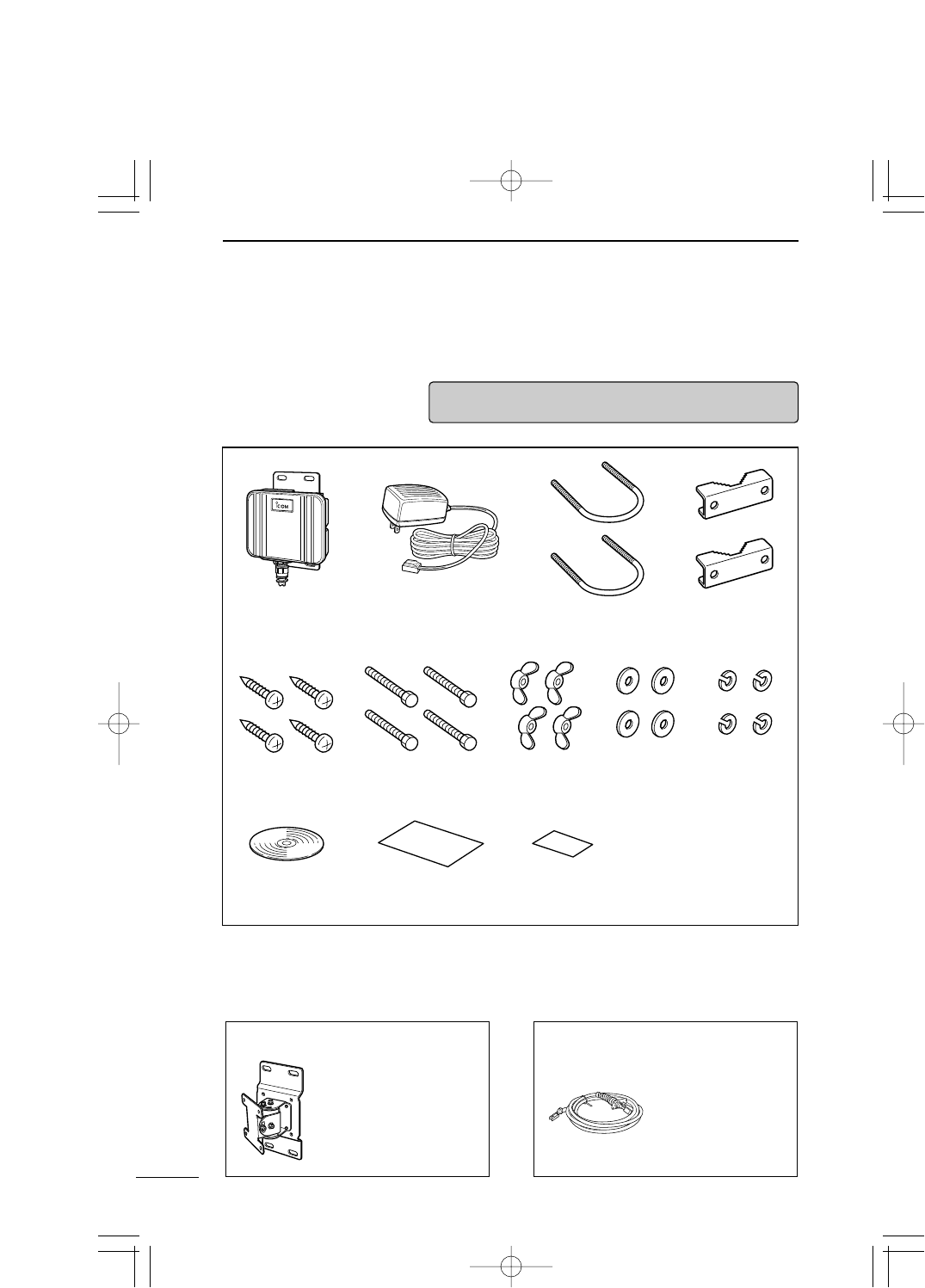
CONTENTS OF STANDARD PACKAGE
■Checking Contents
of Package
This SB-110 package contains the components below.
Before using SB-110, check whether all of those
components are contained completely in the package.
If any of the components is not contained in the package, please
contact the shop or our service section.
CD-ROM
AC Adapter
Tapping Screws
A0 6 x 30
Hexagonal Head Bolts
M6 x 50
U Bolts Mast ClampsSB-110 Main Unit
(Cable length: 3m)
Wing Nuts
M6
Flat Washers
M6
S Washers
M6
Instruction Manual User Registration/
Warranty Card
■Optional Accessories
Adjustable Range:
MB-89: Elevation Angle Bracket
Upper 30/Lower 30 degrees
Left 30/Right 30 degrees
OPC-1135: Extension Cable (20 m)
OPC-1136: Extension Cable (50 m)
For the extension
of Ethernet cable
and power cable.
(As of October 2001)
PDF取説-E_1 02.1.23 10:28 ページv

Contents
vi
Contents
INTRODUCTION ────────────────────i
CONTENTS OF STANDARD PACKAGE ─────────v
■Checking Contents of Package ……………………………v
■Optional Accessories ………………………………………v
Contents ───────────────────────vi
SAFETY PRECAUTIONS(Be sure to read)───────viii
1. BEFORE INSTALLATION ──────────────1
1-1.Name and Function of Component ………………………2
1-2.Radio Communication Function …………………………3
1-3.Using in Building Communication Mode …………………3
1-4.Using in Access Point Mode ………………………………4
1-5.Using Roaming Function …………………………………5
1-6.Notes on Installation ………………………………………7
2. INSTALLATION AND CONNECTION ─────────9
2-1.Installing on Mast …………………………………………10
2-2.Fixing on Wall ……………………………………………11
2-3.How to Connect……………………………………………12
2-4.Before Connecting Existing LAN ………………………13
3. SETTING YOUR PC ────────────────15
3-1.Connecting in Building Communication Mode …………16
3-2.Connecting through Wireless Access Point ……………22
3-3.Preparing WWW Browser ………………………………28
3-4.Checking IP Assigned Address …………………………29
4. SETTING SB-110──────────────────33
4-1.Turning on SB-110 and PC ………………………………34
4-2.Showing Setting Screen …………………………………35
4-3.Changing Wireless Communication Mode ……………36
4-4.Stopping DHCP Server …………………………………37
4-5.Changing IP Address Of SB-110 ………………………38
4-6.Changing Automatic Assignment Start IP Address ……39
5. SETTING SCREEN ─────────────────41
5-1 [Wireless LAN settings] Screen …………………………42
5-2 [Detail settings] Screen …………………………………45
5-3 [IP address] Screen ………………………………………53
5-4 [Routing function] Screen ………………………………59
5-5 [Administration] Screen …………………………………62
6. MAINTENANCE ──────────────────65
6-1 CD-ROM of SB-110 ………………………………………66
6-2 Restricting Access to Setting Screen……………………67
…………………………………………Continue to the next page.
PDF取説-E_1 02.1.23 10:28 ページvi

vii
Contents
6-3 Checking or Saving Settings ……………………………68
6-4 Writing Saved Settings……………………………………69
6-5 Returning Setting to Default State ………………………70
6-6 Upgrading SB-110 ………………………………………74
6-7 When the unit fails ………………………………………77
7. FOR YOUR REFERENCE ──────────────79
7-1 Examples of Routing Setting ……………………………80
7-2 Setting Screen Overview …………………………………83
7-3 List of Initial Values of Setting Items ……………………84
7-4 List of Functions …………………………………………84
7-5 Rating ………………………………………………………85
7-6 Specifications for Ethernet Plug …………………………86
7-7 Glossary ……………………………………………………87
PDF取説-E_1 02.1.23 10:28 ページvii

SAFETY PRECAUTIONS
viii
SAFETY PRECAUTIONS
¡These precautions are intended to ensure that SB-110 is operated safely and cor-
rectly. Follow these instructions to avoid property damage and prevent personal
injury to yourself (user) or others in the vicinity.
¡Before reading the rest of this manual, read and understand the precautions
listed under [ RWarning ] and [ RCaution ] below.
¡After reading this manual, store it in a convenient place for future review.
Be sure to read these precautions in order to use SB-110 safely.
■SB-110
Failure to observe the precautions listed here could result in
death of or serious injury to the user or those near the user.
◎Do not touch SB-110 with moistened
hands.
Otherwise, you may get an electric shock.
◎Do not put any heavy thing on the
connecting cable or pinch it.
Otherwise, the cable may be damaged,
a it may catch fire, you may get an
electric shock and SB-110 may
become out of order.
◎
Do not machine, bend by force, twist,
pull or heat the connecting cable.
Otherwise, the cable may be damaged,
a it may catch fire, you may get an
electric shock and SB-110 may
become out of order.
◎SB-110 is adjusted fully. Do not
disassemble or remodel SB-110. Do
not repair SB-110 by yourself.
Otherwise, a it may catch fire, you may
get an electric shock and SB-110 may
become out of order.
◎Discontinue use immediately if SB-
110 emits smoke, an abnormal odor,
or an abnormal noise.
Otherwise, a it may catch fire, you may
get an electric shock and SB-110 may
become out of order. Remove the AC
adapter and all the cables from SB-110
immediately. Confirm the smoke disap-
pears and contact the shop or our ser-
vice section.
◎
Do not install SB-110 at an unsuitable
place where the structural strength is
insufficient.
Otherwise, SB-110 may drop and
become out of order due to vibration or
wind and people may be injured.
◎Do not install SB-110 at any crowded
area.
Otherwise, people may contact SB-110,
may fall to the ground or may be injured.
◎Do not install SB-110 near the power
line or distribution line.
Otherwise, SB-110 cable may contact
the power line or distribution line, may
be short-circuited or heated. Moreover,
people may get an electric shock or a it
may catch fire.
◎Do not touch SB-110, antenna cable
or power cable when it thunders.
Otherwise, you may get an electric shock.
◎Use the specified articles and
accessories only.
Otherwise, a it may catch fire, you may
get an electric shock and SB-110 may
become out of order.
◎Be sure to connect the power supply
to the DC connector only.
Otherwise, a it may catch fire, you may
get an electric shock and SB-110 may
become out of order.
R
Warning
PDF取説-E_1 02.1.23 10:28 ページviii
ix
SAFETY PRECAUTIONS
R
Caution
Failure to observe the precautions listed here could result in
personal injury or property damage.
◎Do not put SB-110 on any unstable
place where is shaky or not level.
Otherwise, SB-110 may drop and
become out of order or you may fall to
the ground and may be injured.
◎Do not use any unsuitable material
of which strength is insufficient
(antenna mast, bracket, etc.) or
corrosive material.
Otherwise, SB-110 may drop and become
out of order or you may be injured.
◎Do not use SB-110 in the site where
strong magnetic fields or static elec-
tricity is generated or where is ex-
posed to the temperature or humidity
exceeding the specifications pre-
scribed in the instruction manual.
Otherwise, Unrecoverable permanent
damage may occur.
◎When it thunders, remove the AC
adapter from the outlet to stop
operation. Do not Install, service,
connect or disconnect cables.
Otherwise, a it may catch fire or you
may get an electric shock.
◎Do not use paint thinner or solvent
to clean SB-110.
Otherwise, the case material may
degrade and the paint may peel.
Usually, clean SB-110 with a soft cloth.
If the case is stained considerably, wipe
the case using a cloth dampened with
detergent that has been diluted with
water.
◎Do not disassemble SB-110.
Otherwise, you may be injured or get
an electric shock, SB-110 may become
out of order or the radio disturbance
may occur.
◎Do not perform the installation work
at an unstable site.
Otherwise, you may fall to the ground
or may be injured.
◎Do not drop the device or give a
considerable shock to it.
Otherwise, you may be injured or SB-
110 may become out of order.
◎Do not use SB-110 near the TV set or
radio.
Otherwise, the radio disturbance may
occur in SB-110, TV set or radio.
◎Do not expose SB-110 to the direct
sunlight, the air from the air
conditioner or any unsuitable places
where the temperature varies
considerably.
Otherwise, SB-110 may be deformed or
discolored, a it may catch fire or SB-
110 may become out of order.
◎Follow instructions on manuals and
make right connections described in
this manual. Do not make a mistake
in connection to SB-110.
Otherwise, Unrecoverable permanent
damage may occur.
◎If SB-110 is not used for a long time,
remove the AC adapter from SB-110
for safety.
Otherwise, SB-110 may overheat,
catch fire or become out of order.
■SB-110 (continued from the previous page)
PDF取説-E_1 02.1.23 10:28 ページix
SAFETY PRECAUTIONS
x
SAFETY PRECAUTIONS
■AC Adapter (Accessory)
◎Do not use the AC adapter for any
other devices.
Otherwise, a it may catch fire, you may
get an electric shock and SB-110 may
become out of order.
◎Use the AC adapter in AC 120 V
power supply only.
Otherwise, a it may catch fire, you may
get an electric shock and SB-110 may
become out of order.
◎Be sure to hold the plug body when
you plug and unplug the AC cable.
Otherwise, a it may catch fire, you may
get an electric shock and SB-110 may
become out of order.
◎Use AC outlet with enough capacity
to accomodate the AC adapter of
SB-110.
Otherwise, a it may catch fire, you may
get an electric shock and SB-110 may
become out of order.
◎Do not tie the AC cables in a bundle.
Otherwise, the cables is heated and a it
may catch fire.
◎Do not touch the AC plug and
devices with moistened hands.
Otherwise, you may get an electric
shock.
◎Insert the AC plug into the outlet
completely.
If the plug is not inserted completely, a
it may catch fire or you may get an
electric shock.
◎Do not modify, bend illegally, twist
or heat cables..
Otherwise, the cable may be damaged,
a it may catch fire, you may get an
electric shock and SB-110 may
become out of order.
◎Do not put any heavy thing on the
AC cable or pinch it.
Otherwise, the cable may be damaged,
a it may catch fire, you may get an
electric shock and SB-110 may
become out of order.
◎If a metal part of the AC plug and its
surroundings are covered with dust,
wipe it with a dry cloth completely.
Otherwise, a it may catch fire.
◎If the AC cable is damaged or if the
AC cable cannot be inserted
completely, do not use such cable.
Otherwise, a it may catch fire, you may
get an electric shock, SB-110 may be-
come out of order, data may be lost.
Please contact the shop or our service
section.
R
Warning
Failure to observe the precautions listed here could result in
death of or serious injury to the user or those near the user.
PDF取説-E_1 02.1.23 10:28 ページx

PDF取説-E_1 02.1.23 10:28 ページxi

CHAPTER 1
BEFORE INSTALLATION
1-1. Name and Function of Component …………………………………………………2
1-2. Radio Communication Function ……………………………………………………3
1-3. Using in Building Communication Mode ……………………………………………3
1-4. Using in Access Point Mode …………………………………………………………4
■Notes on Use of Access Point Mode ……………………………………………4
1-5. Using Roaming Function ……………………………………………………………5
■Notes on Use of Roaming Function ……………………………………………6
1-6. Notes on Installation …………………………………………………………………7
■Directional Characteristics of Antenna …………………………………………7
This chapter describes what you should consider and prepare when you in-
stalling SB-110.
PDF取説-E_1 02.1.23 10:28 ページ1
2
BEFORE INSTALLATION
1
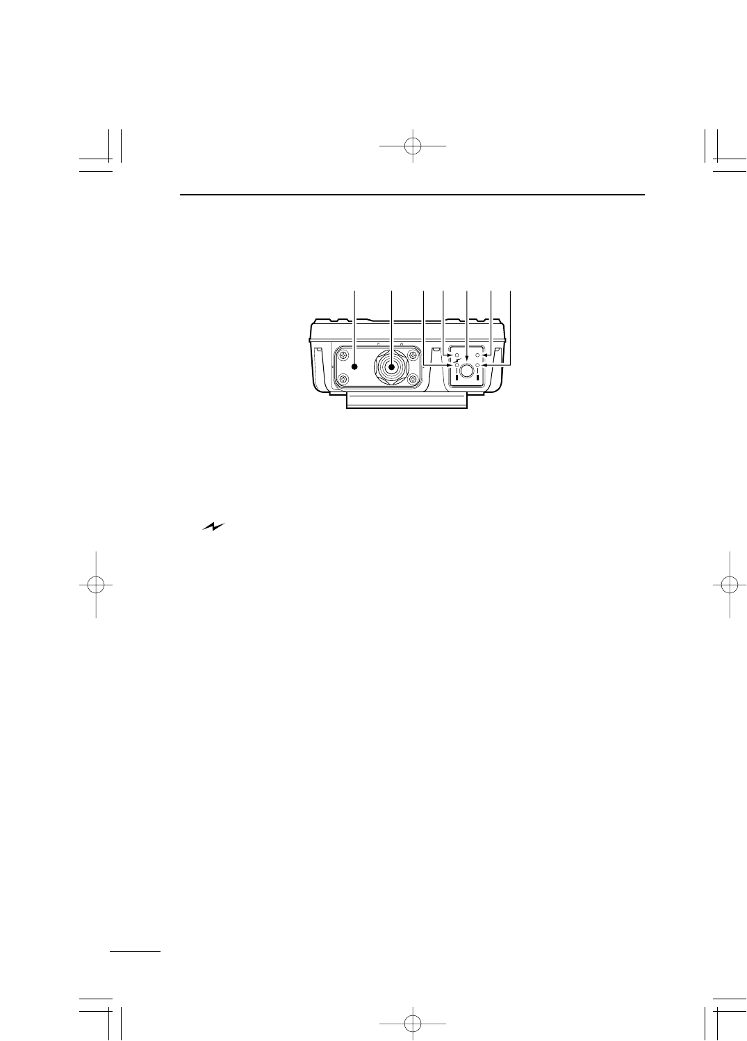
1-1 Name and Function of Component
qEthernet cable/DC cable
Used to connect SB-110 to the wired LAN (Hub).
This cable is for straight connection.
Connect the AC adapter, which comes with SB-110, to the DC cable.
w[ ] (Red) indicator
Turns on when the connection to SB-110 has been established. The indicator turns off when:
¡All the radio devices is in no-communication state for one or two minutes.
¡All the radio devices is out of radio transmission area for one or two minutes.
e[PWR] (Green) indicator
Turns on when SB-110 turns on.
Blinks alternately with the [MODE] indicator in the [UTILITY] mode operation.
Blinks simultaneously with the [MODE] indicator in the [INITIALIZATION] mode operation.
r<MODE> button
Use for an operation in the [UTILITY] mode and [INITIALIZATION] mode.
t[MODE] (Green) indicator
Blinks in the [UTILITY] mode and [INITIALIZATION] mode.
Blinks alternately with the [PWR] indicator in the [UTILITY] mode operation.
Blinks simultaneously with the [PWR] indicator in the [INITIALIZATION] mode operation.
y[LAN] (Red) indicator
Turns on when the connection to LAN has been established normally.
Turns off when the Ethernet cable is not connected.
Blinks when data is communicated.
※
A plate to fix SB-110 cable. If you connect a commercial ground cable, fix it with the screws for
this plate.
PWR MODE
MODE
LAN
※qwerty
PDF取説-E_1 02.1.23 10:28 ページ2
3
BEFORE INSTALLATION 1
1
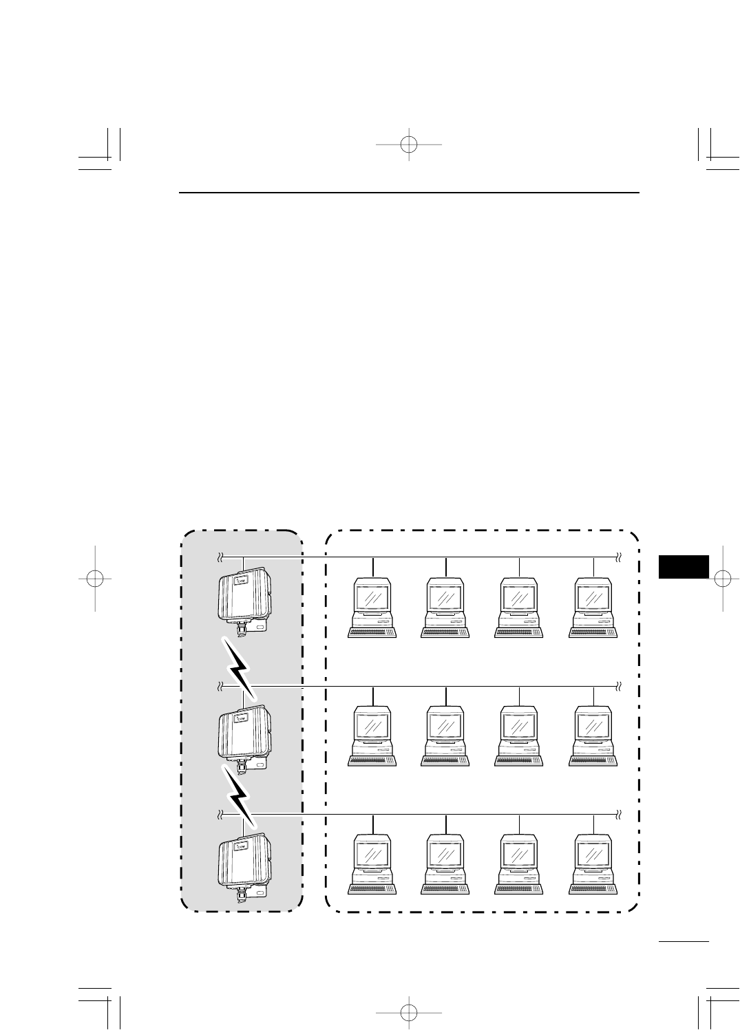
1-2 Radio Communication Function
In this network system, by connecting those units facing to each other in the Wire-
less Bridge mode, those wired LAN can be connected in a wireless system.
* The maximum number of SB-110s used simultaneously is 256. However, it is
recommendable to use ten units or less.
1-3 Using in Building Communication Mode
The three ways (two modes and one function) below are available as connection method
for SB-110 to build up the wireless network.
●Building Communication (Wireless Bridge) mode (see 1-3)
●Access Point mode (see 1-4)
●Roaming function (see 1-5)
SB-110 operates in the Building Communication mode by default or when all the settings
are initialized. Those two modes cannot be used simultaneously.
Ethernet LAN
Radio Transmission Area
Wired LAN
Ethernet LAN
Ethernet LAN
1,024 units - The maximum number of the usableA maximum of 256 units
PDF取説-E_1 02.1.23 10:28 ページ3
4
BEFORE INSTALLATION
1
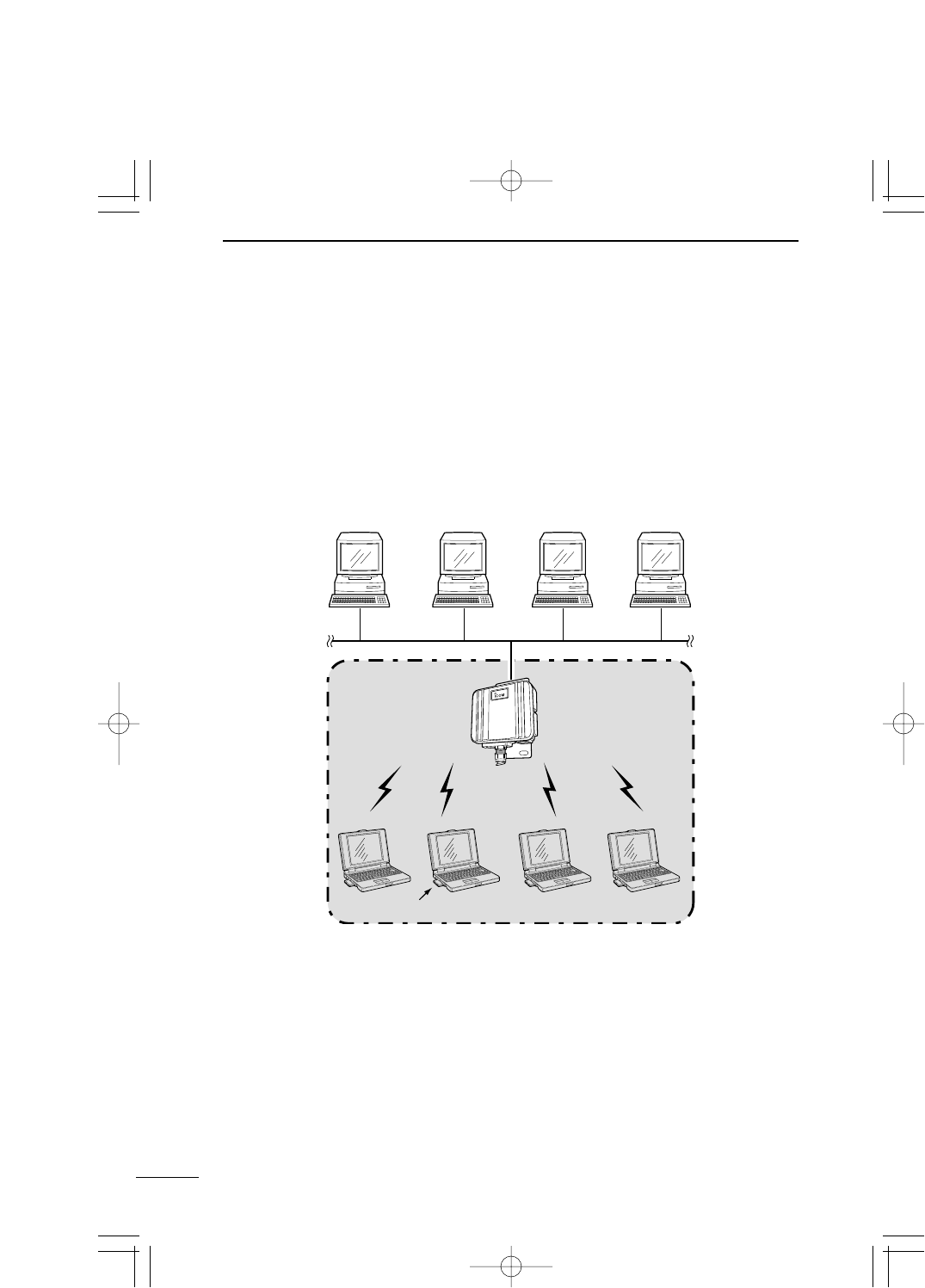
1-4 Using in Access Point Mode
In this wireless LAN system, wireless terminals are connected to each other through
SB-110 by wireless or a terminal connected to SB-110 through Ethernet is connected
to a wireless terminal through SB-110 by wireless.
If you use SB-110 as an access point, you need to change the default setting (☞see 4-3)
using a PC connected to SB-110 through a hub on Ethernet LAN.
* The maximum number of SB-110s used simultaneously is 256. However, it is
recommendable to use ten units or less.
■Notes on Use of Access Point Mode
◎The Building Communication mode is disabled when
the Access Point mode (☞see 4-3) is enabled.
◎Any terminal connected to SB-110 by wireless must
be equipped with our 11 Mbps wireless LAN card.
◎If [ESS ID] or [WEP] (☞see page 27) specified in a
wireless terminal is different from that of SB-110, any
communication to such wireless terminal is
unavailable.
Wireless LAN Card
Wireless LAN
A maximum of 256 units are acceptable.
Wired LAN
Radio Transmission
Area
Ethernet LANEthernet LAN
PDF取説-E_1 02.1.23 10:28 ページ4
5
BEFORE INSTALLATION 1
1
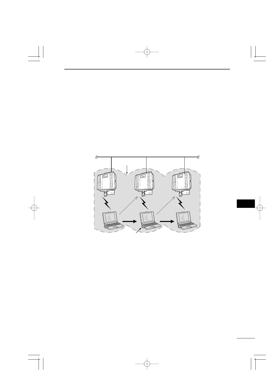
If SB-110 is located at several places on Ethernet LAN so that the radio
transmission areas can overlap each other, the wireless terminal can transmit
while moving from a radio transmission area to another. Consequently, the radio
transmission area can be extended.
If you use the roaming function, you need to change the default setting (☞see 4-3) into
the Access Point mode using a PC connected to SB-110 through a hub on Ethernet
LAN.
* To connect several SB-110s, use a hub.
1-5 Using Roaming Function
■Notes on Use of Roaming Function (☞See the next page)
Ethernet LAN
Radio Transmission Area
Move Move
SB-110 is switched
from one to another
as the wireless
terminal moves.
SB-110 is switched
from one to another
as the wireless
terminal moves.
Wireless LAN card
PDF取説-E_1 02.1.23 10:28 ページ5
6
BEFORE INSTALLATION
1
1-5 Using Roaming Function (continued from the previous page)
■Notes on Use of Roaming Function
◎The roaming function is enabled in the Access Point mode and, therefore, this function
cannot be used in the Building Communication mode.
◎Any terminal connected to SB-110 by wireless must be equipped with our 11 Mbps
wireless LAN card.
◎In the radio transmission area where a wireless terminal moves around, [ESS ID] (☞
see 5-1) and [WEP] (☞see 5-2) of the wireless terminal must be the same as those of
SB-110 used in the roaming function. If [ESS ID] or [WEP] specified in the wireless
terminal is different from that of SB-110, any communication to such wireless terminal is
unavailable.
◎Any wireless LAN terminal operates as a network group which is the same as that of
wired LAN terminal, including the roaming area. Therefore, do not used the roaming
function together with the Routing mode (☞see 5-3).
Otherwise, the communication becomes unavailable due to invalid network address.
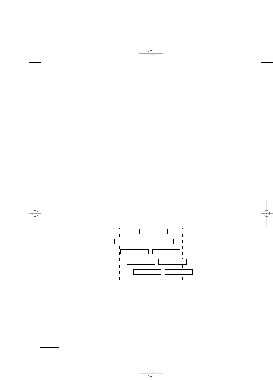
◎To avoid radio interference, when any channel is changed, keep a sufficient distance
equivalent to four channels or more between the channel to be changed and the other
party's radio access point channel. Otherwise, as shown below, the radio interference
may occur because a part of frequency bands overlap each other. For example, if
Channel 1, Channel 6 and Channel 11 are specified, no radio interference occurs.
2400 2410 2420 2430 2440 2450
Frequency (MHz)
2460 2470 2480
Channel 1
Channel 2
Channel 3
Channel 4
Channel 5
Channel 6
Channel 7
Channel 8
Channel 9
Channel 11
Channel 10
PDF取説-E_1 02.1.23 10:28 ページ6
7
BEFORE INSTALLATION 1
1
1-6 Notes on Installation
Select a suitable installation site with care. Otherwise, the communication may be
interfered or the communication range or speed may be affected.
The installation must meet the conditions below:
◎The installation site should be located at a high place so that nothing can be put on SB-
110. The installation site should not be blocked by any obstruction.
◎The installation site must not be exposed to the direct sunlight nor open to the weather.
◎The installation site must be rigid without any vibration and SB-110 must not drop.
◎Do not locate SB-110s too close to each other or to any other product.
◎Any large-sized obstruction must not be located between the installation sites even tem-
porarily. If any obstruction is located between them, the communication may be inter-
fered.
◎Do not install SB-110 near a radio tower which sends a strong radio wave.
◎Do not install SB-110 near a metal wall of warehouse. A radio wave may be reflected.
◎If the communication is made between the different floors, neither steel beam nor fire-
proof metal material must be embedded in the floor.
◎The total length of Ethernet cable between SB-110 and the hub must be within 100 m.
◎The distance between two SB-110s (built-in antenna type) must be within approxi-
mately 800 m.
◎If SB-110 is used in the Access Point mode, the distance between two SB-110s (built-
in antenna type) must be within approximately 70 m.
◎Two SB-110s (built-in antenna type) must be faced to each other exactly.
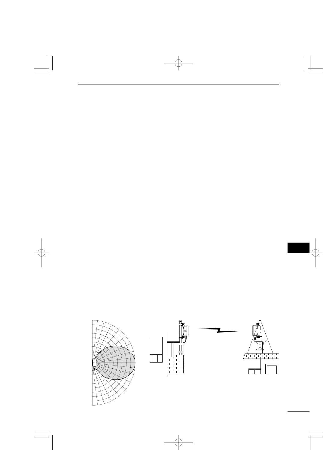
■Directional Characteristics of Antenna
SB-110 (built-in antenna type) has the directionality. When you install two SB-110s, those
antennas must be faced to each other at the same position horizontally and vertically.
Maximum communication distance:
Approximately 800 m
PDF取説-E_1 02.1.23 10:28 ページ7

PDF取説-E_1 02.1.23 10:28 ページ8
CHAPTER 2
INSTALLATION AND CONNECTION
2-1. Installing on Mast ……………………………………………………………………10
■How to Install Elevation Angle Bracket ………………………………………10
2-2. Fixing on Wall ………………………………………………………………………11
2-3. How to Connect ……………………………………………………………………12
2-4. Before Connecting Existing LAN …………………………………………………13
■Checking Network Status ………………………………………………………13
■Setting IP Address ………………………………………………………………13
■Connecting to Existing LAN ……………………………………………………13
This chapter describes how to install SB-110 and how to connect it to the pe-
ripheral devices.
【Remarks】
◎Do not paint the case of SB-110. Otherwise, the radio wave is attenuated by metal
composition contained in the paint and SB-110 cannot show the performance fully.
◎Fix the power cable connected to SB-110 and any other connecting cables to a
suitable position where nobody can touch.
【Installation Work】
When you install SB-110, we assume no responsibility for any building breakage, any
damage resulting from a drop of SB-110 from a high place or unstable site or resulting
from any personal injury nor any accident in any other cases. If SB-110 is must be
installed at such high place or unstable site, be sure to consult an expert engineer.
PDF取説-E_1 02.1.23 10:28 ページ9
10
INSTALLATION AND CONNECTION
2
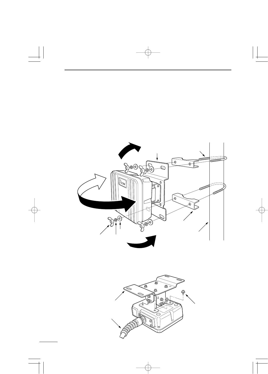
2-1 Installing on Mast
When you install two SB-110 (the built-in antenna type), any obstruction must not be lo-
cated between those SB-110s.
* The installation with the elevation angle bracket (MB-89), an optional accessory, is
shown below as an example:
*
When you use the elevation angle bracket (MB-89), if the mast diameter is small, the U bolt
which comes with SB-110 may contact the SB-110 depending on the adjustment angle.
When you fix SB-110, take care not to contact the U bolt to SB-110 considerably.
SB-110
Flat washer Mast
S washerWing nut
Elevation Angle Bracket
(optional accessory)
Upper: 30 degrees
Left: 30 degrees
Right: 30 degrees
Lower: 30 degrees
U Bolt
Mast clamp
■How to Install Elevation Angle Bracket (Optional Accessory)
Remove a bracket from SB-110 and replace it with the elevation angle bracket (MB-89).
To lock this elevation angle bracket, use the screws for the original bracket.
SB-110
Elevation Angle Bracket
(optional accessory) To lock the elevation angle
bracket, use these four screws
for the original bracket.
PDF取説-E_1 02.1.23 10:28 ページ10
11
INSTALLATION AND CONNECTION 2
2
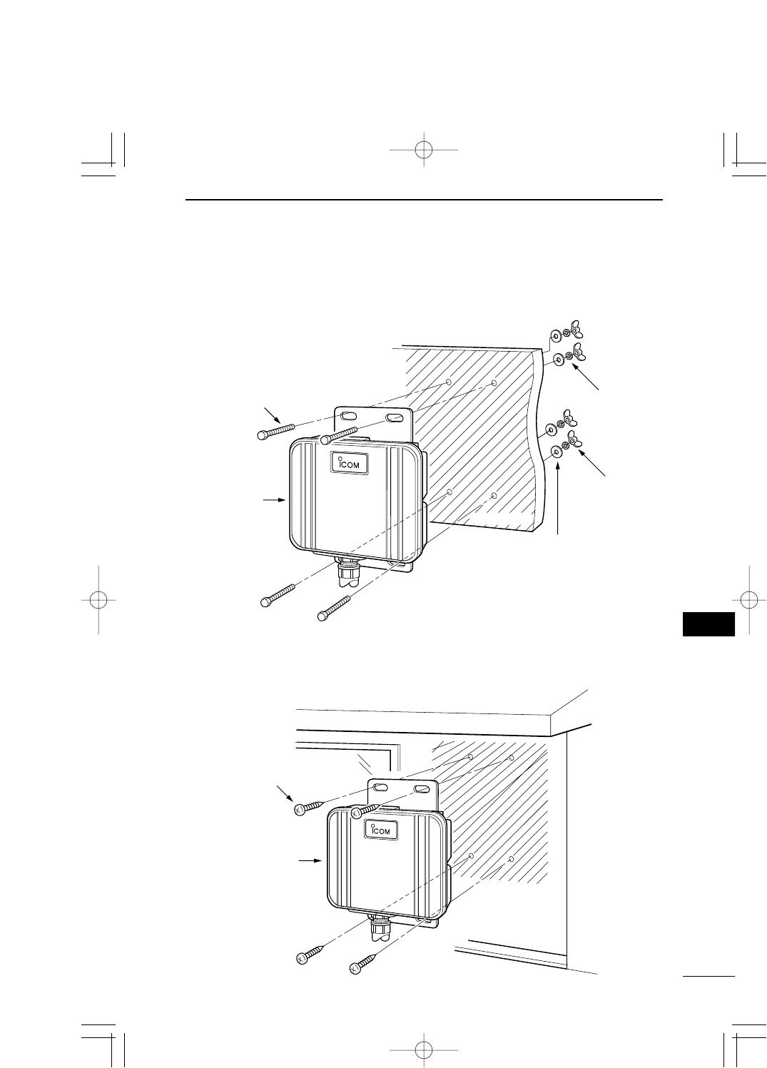
2-2 Fixing on Wall
To fix SB-110 on the wall, use the tapping screws or hexagonal head bolts which come with SB-110.
[Fixing with Hexagonal Head Bolt]
Hexagonal Head Bolt
M6 x 50
SB-110
Wing Nut
Flat Washer
S Washer
Wall Surface
[Fixing with Tapping Screw]
Tapping Screw
(A0) M6 x 30
SB-110
External Wall
PDF取説-E_1 02.1.23 10:28 ページ11
12
INSTALLATION AND CONNECTION
2
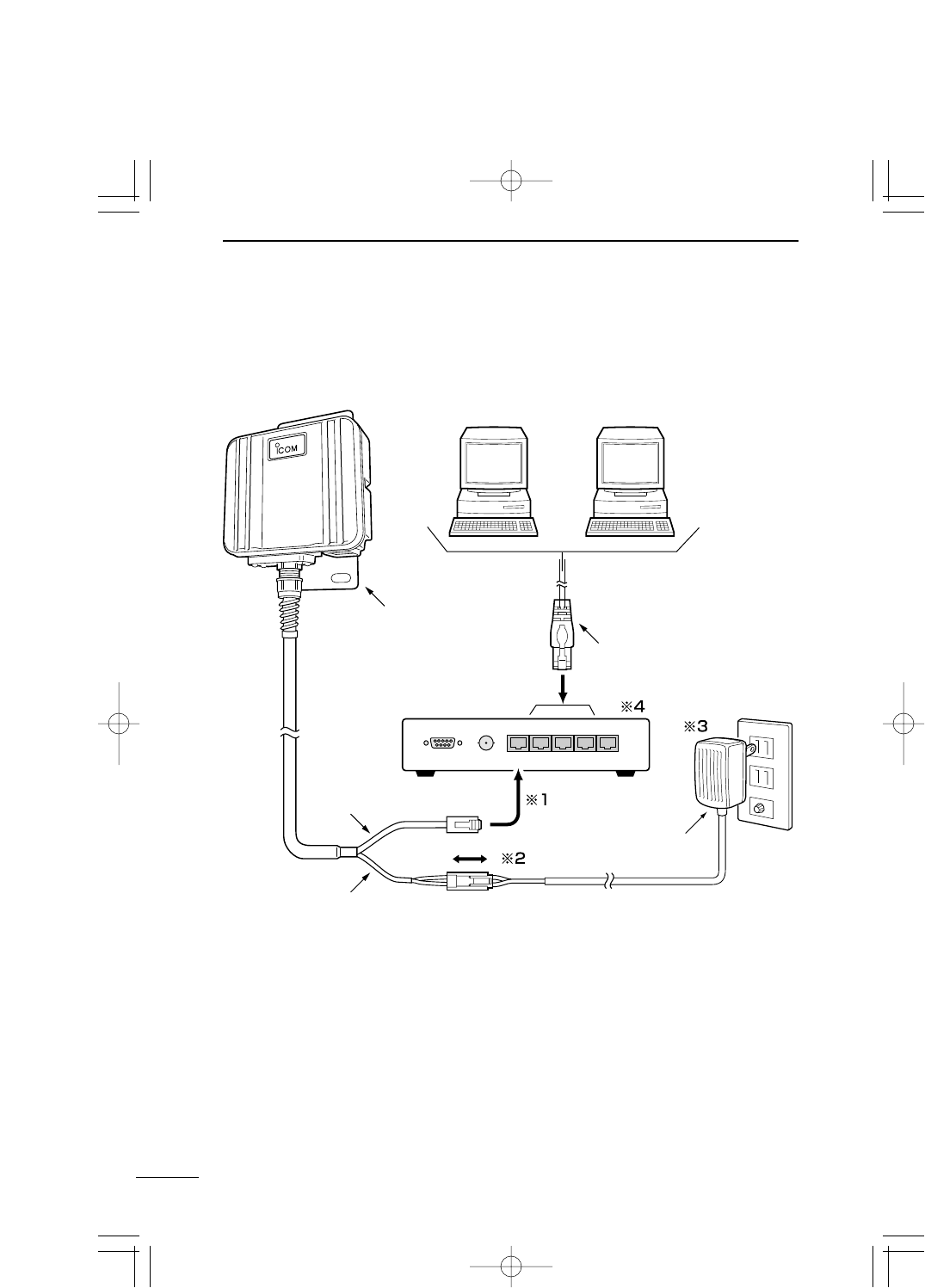
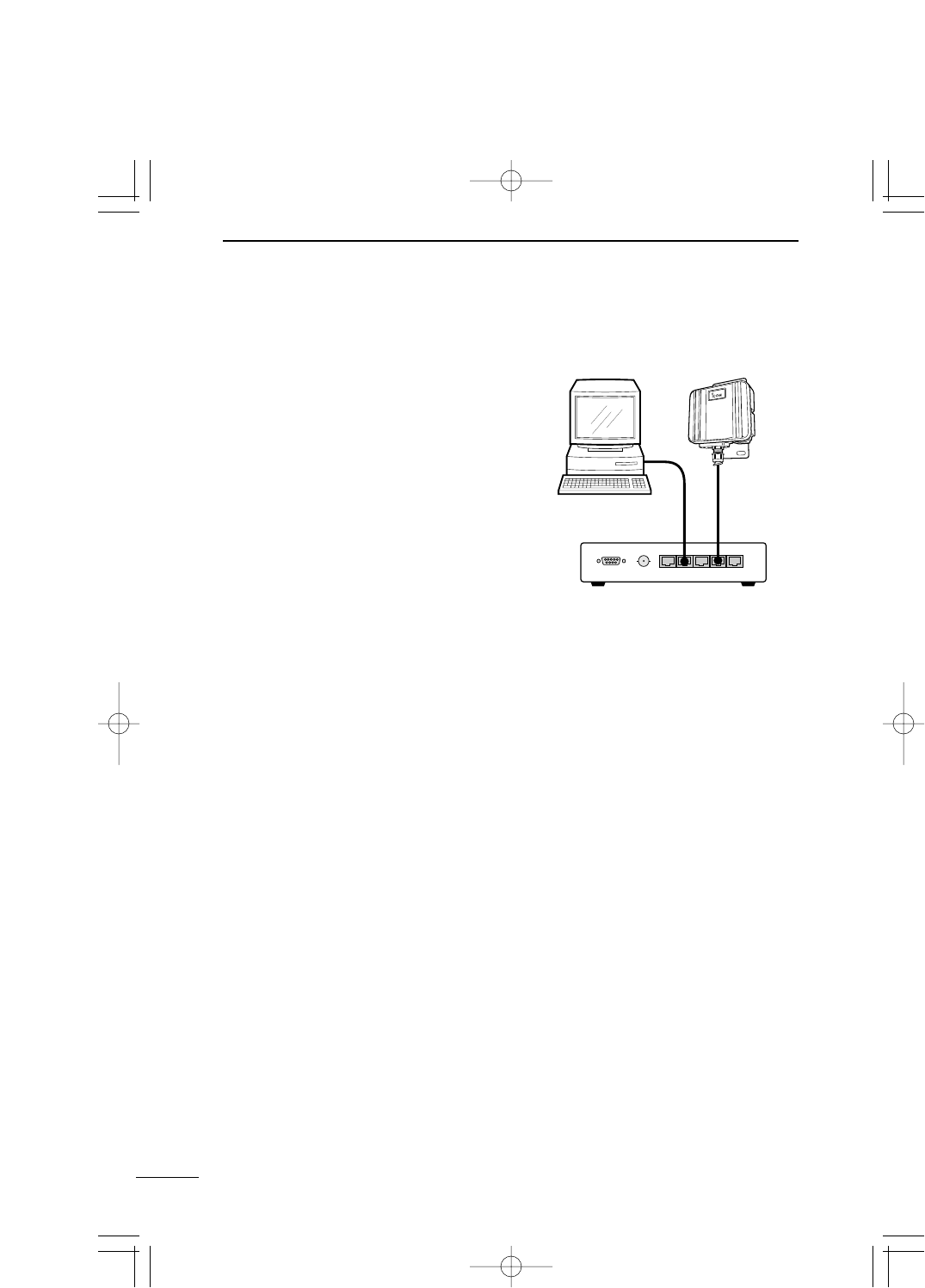
2-3 How to Connect
If SB-110 of a default status is connected to a network in operation, an unexpected
accident may happen, e.g., the conflict in the IP address.
When you set SB-110, refer to "Setting SB-110" (☞see 4) also.
※1.The Ethernet cable of SB-110 is for straight connection. The total length of the
Ethernet cable of SB-110 should be within 100 m. The extended Ethernet cable
should be the Category 5 or higher.
※2.If the DC connector is exposed to rain, wind commercial adhesive tape around
the connector.
※3.The AC adapter is not waterproof. Do not expose it to rain.
※4.SB-110 is available for the hub of the transmission rate 100 Mbps.
PC PC
= × × × ×
Hub (Commercial article)
AD adapter
(Accessory)
AC outlet
SB-110
Ethernet cable
(Straight connection)
Ethernet cable
(Straight connection)
DC cable
PDF取説-E_1 02.1.23 10:28 ページ12

13
INSTALLATION AND CONNECTION 2
2
2-4 Before Connecting Existing LAN
When you connect SB-110 to an existing LAN, you need to assign the IP address to SB-
110 according to the IP address assignment system specified in the LAN in advance.
* To change the IP address of SB-110, refer to "How to Change IP Address" (☞see 4-5).
[Connection to environment that fixed IP address is assigned]
Assign an available IP address to SB-110.
[Connection to environment that the DHCP server function is used]
Change the SB-110 setting to disable the DHCP server function and assign an IP address
which is not assigned automatically.
■Checking Network Status
When a network is built on an existing LAN, please note the points below:
[IP address of each PC on LAN]
For TCP/IP, if an IP address of a network device (e.g., PC) on the network is the same as
that of SB-110, any communication cannot be made between SB-110 and such network
device. Moreover, the entire network may be affected.
If any network device on an existing network has the IP address [192.168.0.1], you need to
change the default IP address of SB-110 (☞see 4-5) before connecting SB-110 to such
existing network.
When you assign an IP address to network devices statically, take care not to assign the
same IP address to those network devices. Even when you assign the IP address dy-
namically, you need to change the setting so that the IP addresses assigned by the DHCP
server function are different from the IP address of SB-110. Please note that the broadcast
address cannot be assigned to any device on the network.
■Setting IP Address
When the IP address of any other network which you want to connect is the same as that
of SB-110, change the IP address into one specified in the LAN.
* For how to set it, refer to "How to Change IP Address" (☞see 4-5).
■Connecting to Existing LAN
Connect to the LAN referring to "How to Connect" (☞see 2-3).
PDF取説-E_1 02.1.23 10:28 ページ13

PDF取説-E_1 02.1.23 10:28 ページ14

CHAPTER 3
SETTING YOUR PC
3-1. Connecting in Building Communication Mode……………………………………16
■Connecting to Ethernet Cable of SB-110 ……………………………………16
■Setting TCP/IP Protocol
[Windows Me] ……………………………………………………………………16
[Windows 2000] …………………………………………………………………19
[Mac OS] …………………………………………………………………………21
3-2. Connecting through Wireless Access Point ………………………………………22
■Preparing Wireless LAN Card …………………………………………………22
■Setting TCP/IP Protocol
[Windows Me] ……………………………………………………………………22
[Windows 2000] …………………………………………………………………25
■Setting Wireless LAN Card ……………………………………………………27
3-3. Preparing WWW Browser …………………………………………………………28
3-4. Checking IP Assigned Address ……………………………………………………29
[Windows Me] ……………………………………………………………………29
[Windows 2000] …………………………………………………………………30
[Mac OS] …………………………………………………………………………31
This chapter describes how to set a PC which communicates with SB-110.
Read an applicable section as necessary.

16
SETTING YOUR PC
3
3-1 Connecting in Building Communication Mode
This section describes the setting to connect your PC to SB-110 through a hub.
■Connecting to Ethernet Cable of SB-110
Referring to the description of 2-3, connect the Ethernet cable of SB-110 to your PC
through the hub. If your PC has no Ethernet port, you need to mount any commercial Eth-
ernet card to the PC. Mount it to your PC according to the instruction manuals which come
with the PC and Ethernet card.
■Setting TCP/IP Protocol
You need to install a network protocol module (driver) called "TCP/IP" in every PC which
communicates with SB-110. Install the driver referring to the instruction manual which
comes with your Ethernet card.
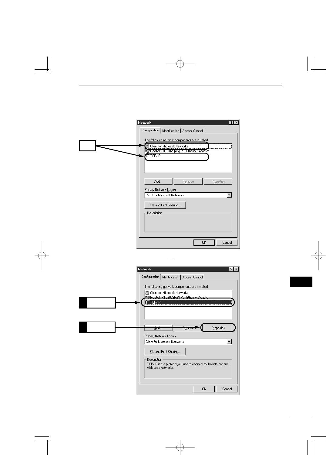
[Windows Me]
1. Select [Start] →[Setting (S)] →[Control Panel (C)] →[Network] icon.
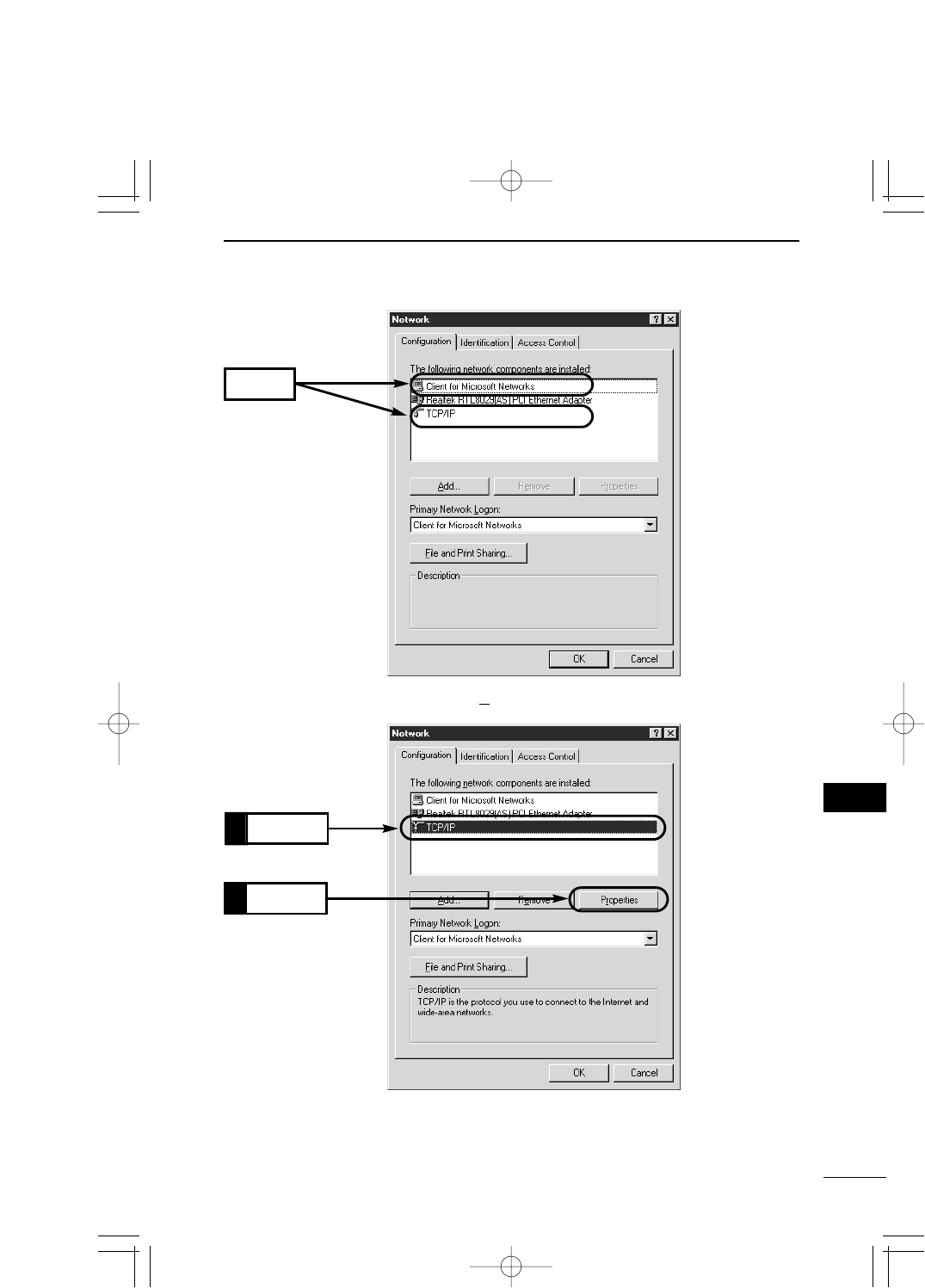
2. Check that [TCP/IP →Name of your Ethernet card] and [Microsoft Network Client] are
displayed in the [Network] screen. If those are not displayed, TCP/IP installation may
fail. Check the installation referring to the instruction manual which comes with your
Ethernet card.
Step 1 Connecting Your PC to SB-110 ━━━━━━━12, 16
Step 2 Setting TCP/IP ━━━━━━━━━━━━━━━━16
Step 3 Preparing WWW Browser ━━━━━━━━━━━28
Step 4 Checking IP Address Assigned by SB-110 ━━━29
PDF取説-E_1 02.1.23 10:28 ページ16
17
SETTING YOUR PC 3
3
3. Click [TCP/IP] and then [Properties (R)].
Check
Click
2.
Click
1.
[Windows Me] (continued from the previous page)
PDF取説-E_1 02.1.23 10:28 ページ17
18
SETTING YOUR PC
3
3-1 Connecting in Building Communication Mode
■Setting TCP/IP Protocol [Windows Me] (continued from the previous page)
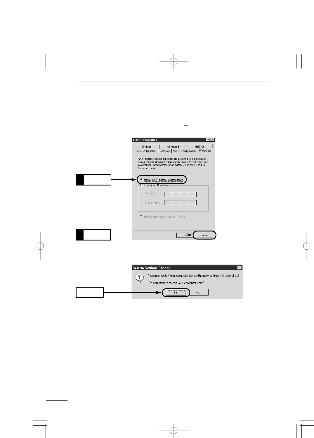
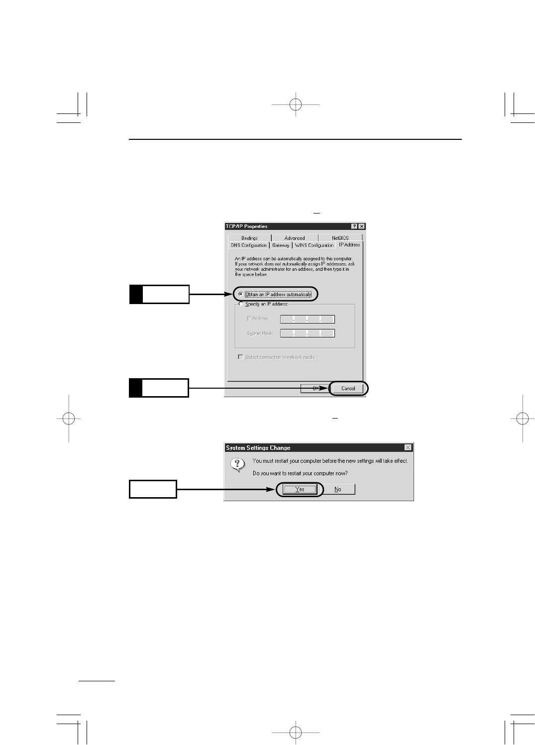
4. Click the [Obtain an IP address automatically (O)] radio button and then [OK].
Click
1.
5. When you are prompted to restart your PC, click [Yes]. The specified setting is en-
abled when the PC has been restarted.
Click
2.
Click
PDF取説-E_1 02.1.23 10:28 ページ18
19
SETTING YOUR PC 3
3
■Setting TCP/IP Protocol (continued from the previous page)
[Windows 2000]
1. Start your PC.
¡The Windows 2000 log-on screen is shown.
2. Log on as the Administrator.
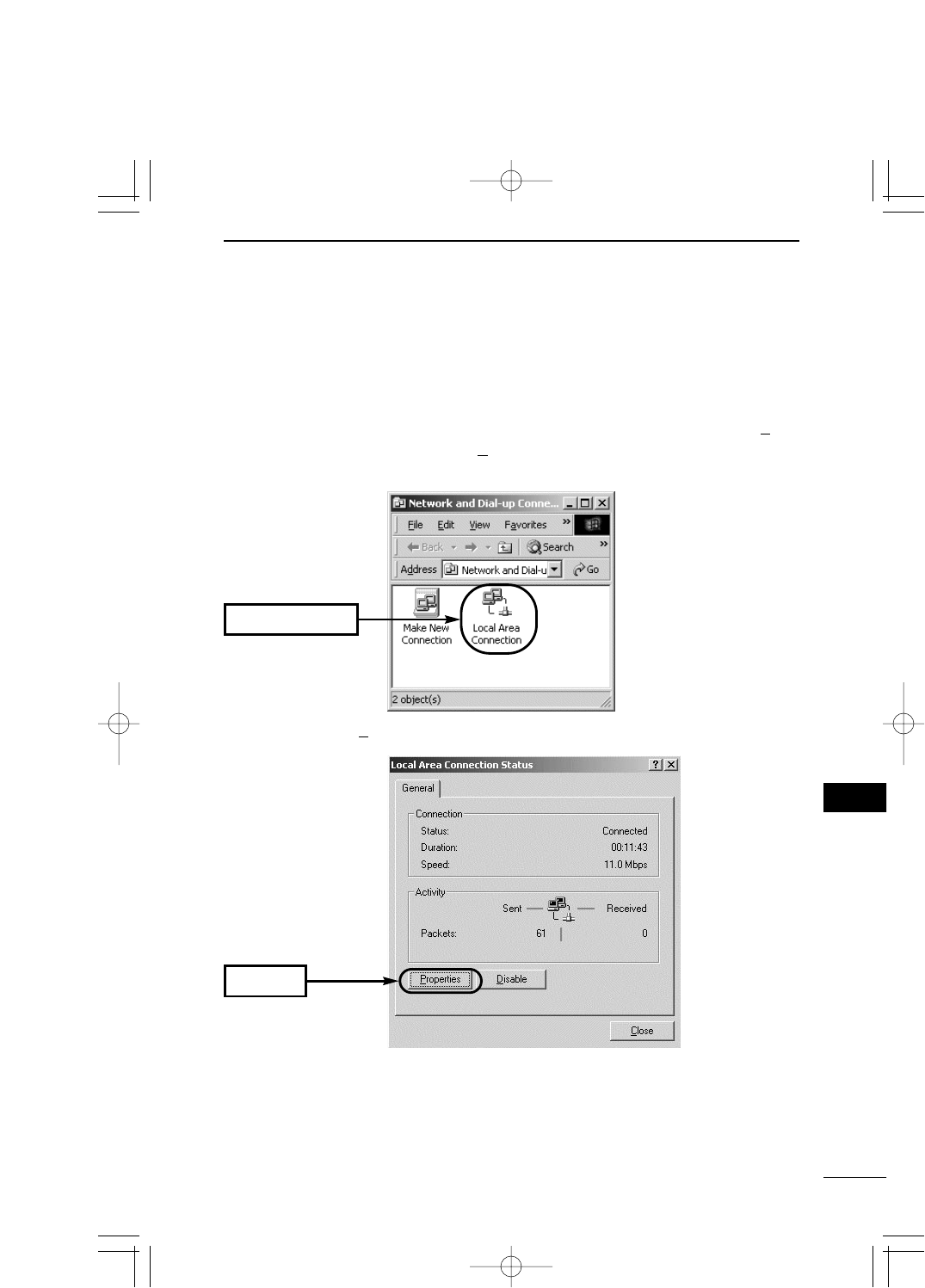
3. When the Windows 2000 desktop has been shown, select [Start] →[Setting (S)] →
[Network and Dial-up Connections (N)] →[Local Area Connection] icon which shows
your Ethernet card name.
4. Click [Properties (P)].
Double-click
Click
PDF取説-E_1 02.1.23 10:28 ページ19
20
SETTING YOUR PC
3
3-1 Connecting in Building Communication Mode
■Setting TCP/IP Protocol [Windows 2000] (continued from the previous page)
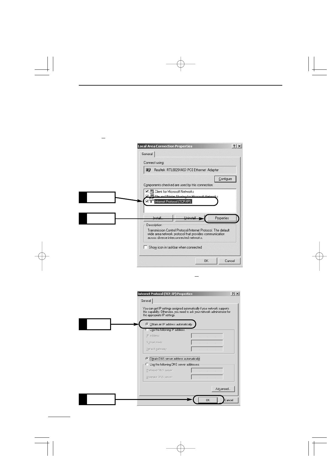
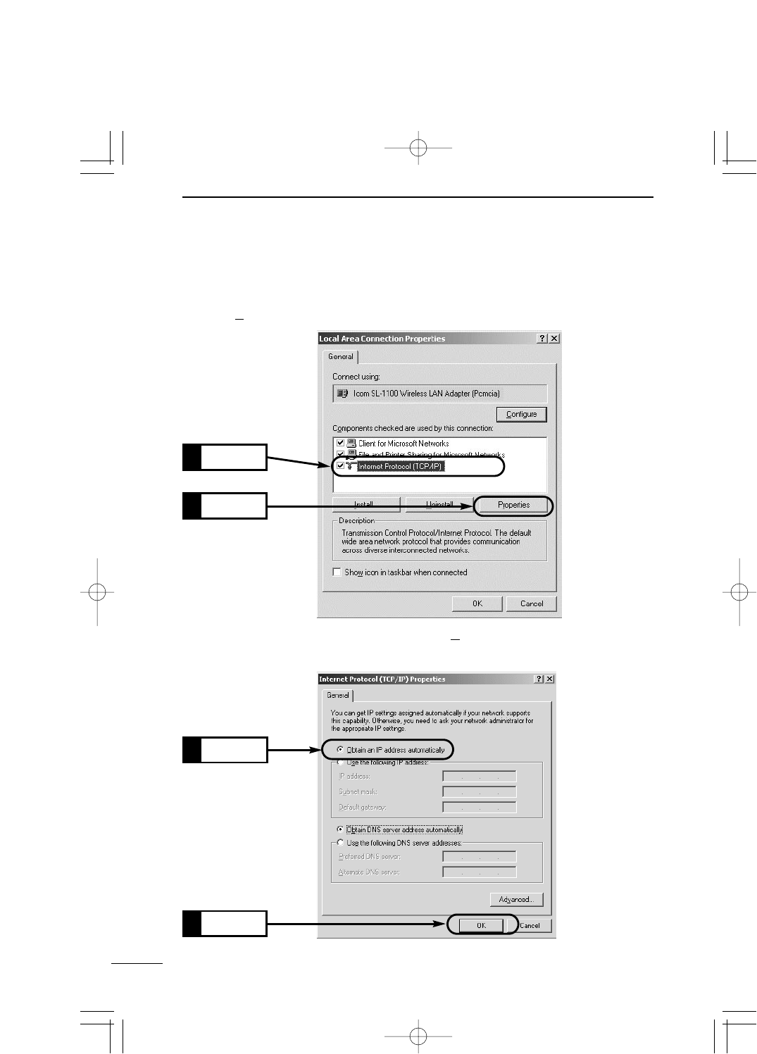
5. If [Internet Protocol (TCP/IP)] is shown, click [Internet Protocol (TCP/IP)] and then [Prop-
erties (R)].
Click
1.
Click
2.
Check
1.
6. Check that [Obtain an IP address automatically (O)] is selected and click [OK] to enable
the specified setting.
Click
2.
PDF取説-E_1 02.1.23 10:28 ページ20
21
SETTING YOUR PC 3
3
[Mac OS]
1. Start your PC.
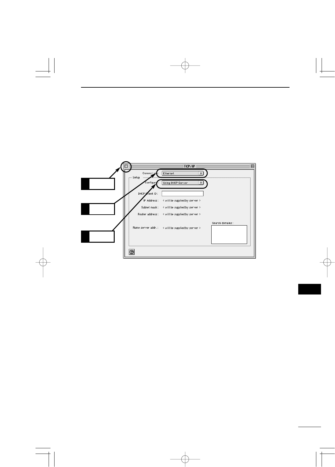
2. When your PC has started up, select [Apple Menu] →[Control Panel] →[TCP/IP].
3. Specify "Ethernet" as [Connect to] and "Using DHCP Server" as [Configure].
4. Click the Close Box on the title bar.
¡The screen is closed and the setting screen is saved.
Select
1.
Click
3.
Select
2.
PDF取説-E_1 02.1.23 10:28 ページ21

22
SETTING YOUR PC
3
3-2 Connecting through Wireless Access Point
Step 1 Preparing Wireless LAN Card ━━━━━━━━━22
This section describes the setting to connect to SB-110 through a wireless access point.
The available operating system is Windows 98, Windows 98SE, Windows Me and Win-
dows 2000.
Step 2 Setting TCP/IP━━━━━━━━━━━━━━━━━22
Step 3 Setting Wireless LAN Card ━━━━━━━━━━━27
Step 4 Preparing WWW Browser ━━━━━━━━━━━28
■Preparing Wireless LAN Card
If SB-110 is set to the Access Point mode (☞4-3), mount any wireless LAN card specified
by us to your PC which can be connected to SB-110 by wireless. If the PC has no PCM-
CIA slot, you need to mount out wireless LAN card adapter to the PC. Mount it according
to the instruction manual which comes with the wireless LAN card adapter
* If the PC has the USB port only, use our wireless LAN unit (SU-11) to communicate with
SB-110 by wireless.
■Setting TCP/IP Protocol
You need to install a network protocol module (driver) called "TCP/IP" in every PC which
communicates with SB-110. Install the driver referring to the instruction manual of your
wireless LAN card.
[Windows Me]
1. Select [Start] →[Setting (S)] →[Control Panel (C)] →[Network] icon.
2. Check that [TCP/IP →Name of your wireless LAN card] and [Microsoft Network Client]
are displayed in the [Network] screen. If those are not displayed, TCP/IP installation
may fail. Check the installation referring to the instruction manual of your wireless LAN
card.
Step 5 Checking IP Address Assigned by SB-110 ━━━29
PDF取説-E_1 02.1.23 10:28 ページ22
23
SETTING YOUR PC 3
3
3. Click [TCP/IP] and then [Properties (R)].
Check
Click
2.
Click
1.
PDF取説-E_1 02.1.23 10:28 ページ23
24
SETTING YOUR PC
3
3-2 Connecting through Wireless Access Point
■Setting TCP/IP Protocol [Windows Me] (continued from the previous page)
4. Click the [Obtain an IP address automatically (O)] radio button and then [OK].
5. When you are prompted to restart your PC, click [Yes]. The specified setting is en-
abled when the PC has been restarted.
Click
1.
Click
2.
Click
PDF取説-E_1 02.1.23 10:28 ページ24

25
SETTING YOUR PC 3
3
■Setting TCP/IP Protocol (continued from the previous page)
[Windows 2000]
1. Start your PC.
¡The Windows 2000 log-on screen is shown.
2. Log on as the Administrator.
3. When the Windows 2000 desktop has been shown, select [Start] →[Setting (S)] →
[Network and Dial-up Connections (N)] →[Local Area Connection] (which shows your
Ethernet card name).
4. Click [Local Area Connection] which shows your wireless LAN card connecting SB-110.
Double-click
Click
PDF取説-E_1 02.1.23 10:28 ページ25
26
SETTING YOUR PC
3
3-2 Connecting through Wireless Access Point
■Setting TCP/IP Protocol [Windows 2000] (continued from the previous page)
5. If [Internet Protocol (TCP/IP)] is shown, click [Internet Protocol (TCP/IP)] and then [Prop-
erties (R)].
6. Check that [Obtain an IP address automatically (O)] is selected and click [OK] to enable
the specified setting.
Click
1.
Click
2.
Click
2.
Check
1.
PDF取説-E_1 02.1.23 10:28 ページ26
27
SETTING YOUR PC 3
3
3-2 Connecting through Wireless Access Point
■Setting Wireless LAN Card
The values of the setting items below of your PC (PC/AT compatible machine) to be con-
nected through the wireless LAN must be the same as those of SB-110. Change the set
values of the PC according to the default setting of SB-110. For how to change the set val-
ues of PC, refer to the instruction manual of your wireless LAN card.
[Network Mode]
Communication is made to a repeater called "Wireless Access Point". Set your PC in the
Infrastructure mode. The wireless communication mode of SB-110 needs to be changed
(☞see 4-3).
[ESS ID]
PCs with the same name are identified as the same work group on the wireless network.
Change the PC setting into "LG". The default setting of SB-110 is "LG".
[Communication Channel]
This is disabled for the communication in the Infrastructure mode. The wireless commu-
nication is made according to the communication channel (☞see 5-2) set in SB-110.
[WEP Function]
When communication is made through a wireless LAN, the communication data is en-
crypted. Disable the WEP security of your PC. The default setting of SB-110 is "Not Use
WEP Key".
【RRemarks】
¡Wireless communication to Macintosh is unavailable.
¡Use a suitable wireless LAN card which supports SB-110. Otherwise, no communication can be made.
¡Write down the value set in SB-110 exactly and be sure to set such value in all the devices to be com-
municated by wireless.
¡While you are changing [Communication Channel], [ESS ID] or [WEP] of SB-110, communication from a
PC connected to SB-110 through a wireless LAN becomes unavailable temporarily. The connection is
ready again when the setting of every device becomes the same.
¡When the WEP function is not used, a third party may connect from the outside. You may encounter a
risk, e.g., unauthorized access, wiretapping, interference, data loss or memory crash. To avoid such
risk, it is recommendable to use the WEP function without fail.
¡To communicate with SB-110 by wireless through the WEP function, our wireless LAN card must be
used.
¡When an operation has become unstable during the wireless communication, move SB-110 or the PC or
change the direction of them.
¡When many PCs access the wireless LAN of SB-110 simultaneously, the communication speed may
decrease considerably. The maximum number of wireless terminals used simultaneously is 256. How-
ever, it is recommendable to use ten terminals or less.
PDF取説-E_1 02.1.23 10:28 ページ27

28
SETTING YOUR PC
3
3-3 Preparing WWW Browser
To set SB-110 through a WWW browser, Microsoft Internet Explorer 4.0 or later or
Netscape Navigator 4.0 or later must be used. When you access the internet through a
PC, whether it is connected by wireless or not, check the "proxy server function" is dis-
abled in the browser setting.
If you want to use the proxy server, do not take SB-110 as an object of the proxy server ac-
cording to the procedure below.
[Microsoft Internet Explorer 5.0]
The procedure to exclude SB-110 from the scope of the proxy server is as follows:
1. Select [Internet Options (O)] in the [Tool (T)] menu.
2. Click the [Connections] tab and then [LAN Settings (L)].
3. Check the [Use a proxy server (X)] check box and click [Advanced (C)].
4. Enter an address of the proxy server of your provider in the [HTTP (H)] text box in the
[Servers] field.
5. Enter the IP address of SB-110 in the [Do not use proxy server for addresses beginning
with (N):] text box in the [Exceptions] field. (Example: 192.168.0.1)
[Netscape 6.0]
The procedure to exclude SB-110 from the scope of the proxy server is as follows:
1. Select [Preferences (E)] in the [Edit (E)] menu.
2. Click [Advanced] and then [Proxies] in the [Category:] field of the [Preferences] dialog
box.
3. Check the [Manual proxy configuration] radio button.
4. Enter an address of the proxy server of your provider in the [HTTP (H)] text box.
5. Enter the IP address of SB-110 in the [Do not use proxy server for domains beginning
with (N):] text box. (Example: 192.168.0.1)
PDF取説-E_1 02.1.23 10:28 ページ28
29
SETTING YOUR PC 3
3
3-4 Checking IP Assigned Address
This section describes how to check an IP address assigned to a PC automatically by the
DHCP server function. Check according to the instruction per operating system below.
[Windows Me]
Check an IP address with a program called "winipcfg.exe" contained in the Windows folder
of the installed operating system.
<How to check>
1. Select [Start] →[Run (R)].
2. Type "winipcfg" in the [RUN] dialog box (falf size) and press the [Enter] key.
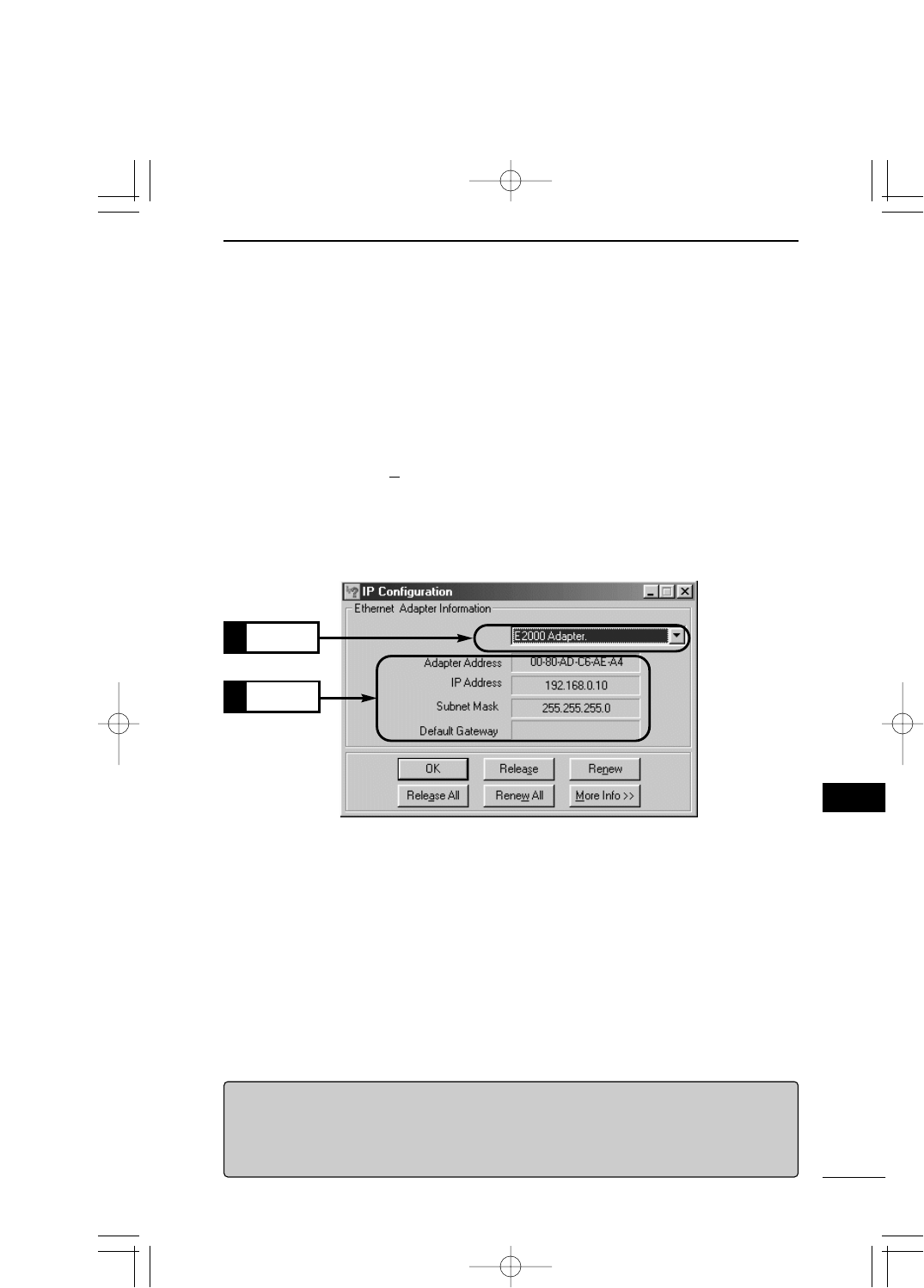
3. Click ▼in the text box and select a name of your Ethernet card or wireless LAN card.
¡When any IP address has been assigned to your PC by the DHCP server, it is dis-
played in the [IP Address] field.
【If automatic assignment fails】
If the network section of IP address of PC is different from that (192.168.0.1) of IP address of SB-110, the
automatic IP address assignment may fail. Check the TCP/IP protocol settings of your Ethernet cared or
wireless LAN card and the cable connection and restart the PC.
When the PC has restarted, check the IP address again according to the procedure above.
<Items displayed on the screen>
◎Adapter Address: MAC address of Ethernet card or wireless LAN card.
◎IP Address: IP address of PC.
◎Subnet Mask: Subnet mask of PC
◎Default Gateway: IP address of network device specified as the default gateway.
Select
1.
Check
2.
PDF取説-E_1 02.1.23 10:28 ページ29
30
SETTING YOUR PC
3
3-5 Checking IP Assigned Address (continued from the previous page)
[Windows 2000]
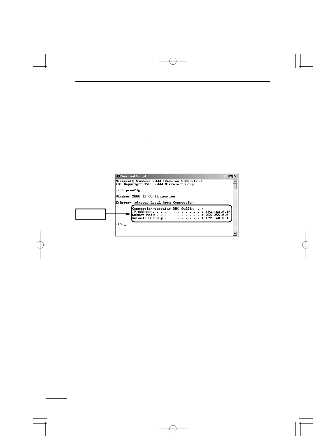
Execute "ipconfig" in the Command Prompt screen.
<How to check>
1. Select [Start] →[Programs (P)] →[Accessories] →[Command Prompt].
2. Type "ipconfig" in the Command Prompt screen and press the [Enter] key.
* For the details of the command line options, refer to the description shown by typing
"ipconfig /?".
3. The IP address assigned to the PC is displayed on the screen.
Check
PDF取説-E_1 02.1.23 10:28 ページ30
31
SETTING YOUR PC 3
3
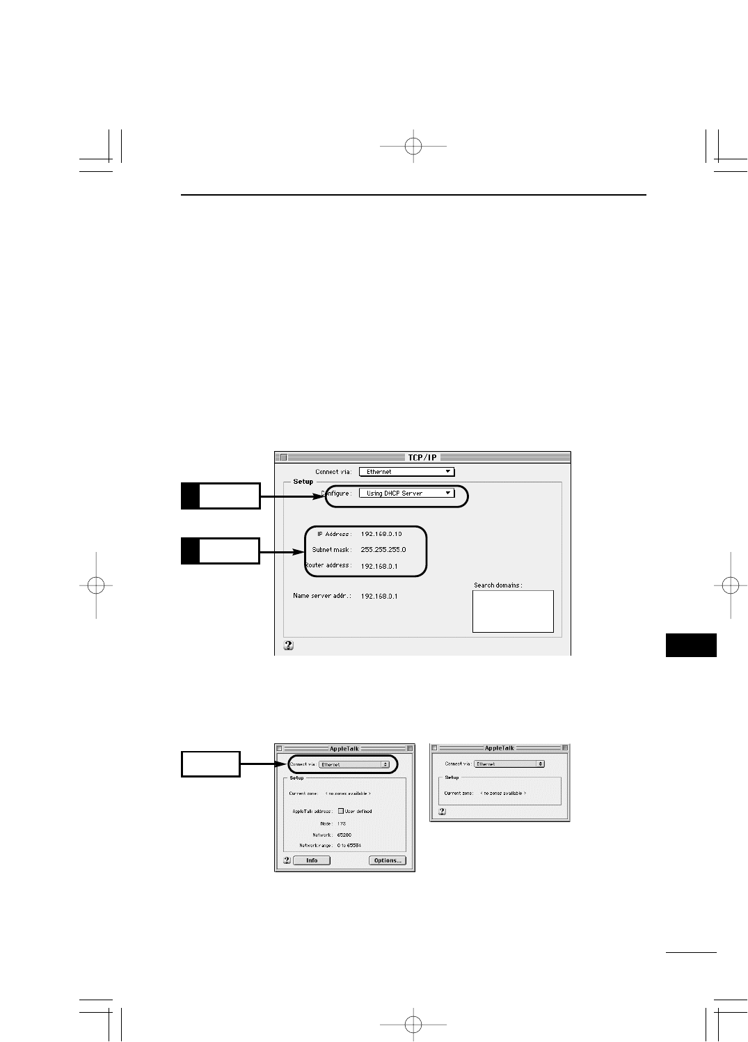
2. To check the MAC address, select [Apple Menu] →[Control Panel] →[AppleTalk].
Then, either of the screens below is shown. Select "Ethernet" in the [Connect via:] field.
*To show the left screen when the right screens is shown, select [Menu] in the menu bar, [User Mode]
and then [Advanced].
Check
[Mac OS]
Even when the PC has started up, the DHCP server does not give the IP address until
communication is made actually (i.e., until you access the internet or you access a mail
server). When <Refer to a server> is displayed on each item on the screen shown by the
procedure below, perform the communication once and then check again.
* The operation screen or any other details may vary depending on your operating system
version.
<How to check>
1. Select [Apple Menu] →[Control Panel] →[TCP/IP].
¡If any IP address is assigned to the PC by the DHCP server, it is displayed on the [IP
Address] field.
Select
1.
Check
2.
PDF取説-E_1 02.1.23 10:28 ページ31
32
SETTING YOUR PC
3
3-5 Checking IP Assigned Address
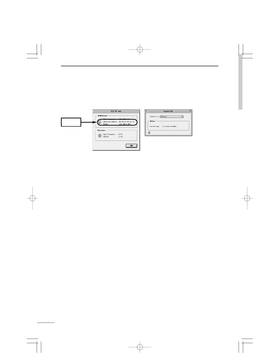
[Mac OS] (continued from the previous page)
3. Click [Info].
To show the left screen when the right screens is shown, select [File] in the menu bar and then [Get Info].
Check
PDF取説-E_1 02.1.23 10:28 ページ32

CHAPTER 4
SETTING SB-110
This chapter describes the setting procedure to use SB-110 for the first time
or to initialize the entire configuration. To perform setting using a WWW
browser from a PC connected to SB-110 by wireless, you need to change
the communication mode (☞see 4-3) from another PC connected to SB-110
through a hub as a first step. Moreover, check that the details of wireless
LAN setting of the PC comply with those of SB-110 (☞see page 27).
4-1. Turning on SB-110 and PC…………………………………………………………34
4-2. Showing Setting Screen ……………………………………………………………35
4-3. Changing Wireless Communication Mode ………………………………………36
4-4. Stopping DHCP Server ……………………………………………………………37
4-5. Changing IP Address Of SB-110 …………………………………………………38
4-6. Changing Automatic Assignment Start IP Address ……………………………39
PDF取説-E_1 02.1.23 10:28 ページ33
34
SETTING SB-110
4
4-1 Turning on SB-110 and PC
Through a hub, connect SB-110 to a PC used for setting.
[Remarks]
◎In the default setting, a wireless terminal cannot
connect to SB-110 through an access point (☞
see 4-3).
◎When you set SB-110, even if SB-110 is used
for several PCs on a network, disconnect one of
those PCs from the network.
◎The PC used to set SB-110 should be config-
ured according to "Connecting in Building Com-
munication Mode" (☞see 3-1). Then, the IP
address of wired terminal is obtained from SB-
110 automatically.
1. Turn on SB-110 and the hub.
2. Check that the [PWR] (Green) indicator and [LAN] (Red) indicator turn on. If one of or
both of them turns off, check that the device power supply and cables are connected
correctly.
3. Turn on the PC connected to the hub.
4. Check that the IP address is assigned from SB-110 (☞3-4).
* When the IP address is not assigned, the SB-110 setting screen cannot be shown.
Check the TCP/IP setting, etc. in "Connecting in Building Communication Mode"
(☞3-1) again.
= × × × ×
Wired terminal
SB-110
192.168.0.1
HUB
PDF取説-E_1 02.1.23 10:28 ページ34
35
SETTING SB-110 4
4
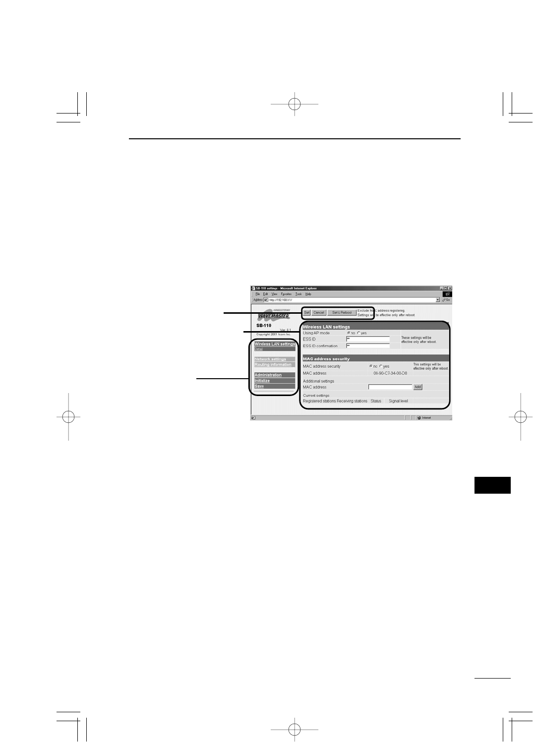
4-2 Showing Setting Screen
<How to operate>
1. Start a WWW browser.
* This WWW browser is Internet Explorer 5.0.
2. Specify "http://192.168.0.1" (default setting). This is URL of SB-110.
¡The [Wireless LAN Settings] screen is shown.
■[Wireless LAN Settings] Screen
Setting Screen
Selection Menu
[Set] / [Cancel] /
[Set & Reboot] Button
■Setting Screen Selection Menu
All the Setting Screen titles are shown. When you click any of the titles, the corresponding
screen is shown.
¡
Wireless LAN settings (Detail settings)
Set the wireless communication mode,
WEP and MAC address security.
¡IP address
Set the routing mode, IP address of SB-
110 and DHCP server.
¡Routing function
Set when you define packet routing.
¡Administration
Set the manager ID, SYSLOG function
and operation to upgrade SB-110.
¡Initialize
Set when you return the configuration SB-
110 to a default state.
¡Save
Operate when you check the details of
SB-110 setting or when you save such
details as a configuration file.
¡[Set] / [Cancel] / [Set & Reboot]
Register the details of setting in the dis-
played menu screen or cancel them.
When you restart the system to enable
the details of setting, operate the [Set &
Reboot] button.
¡Setting Screen Display Area
A screen selected in the Setting Screen
Selection menu is shown.
Setting Screen Display Area
PDF取説-E_1 02.1.23 10:28 ページ35
36
SETTING SB-110
4
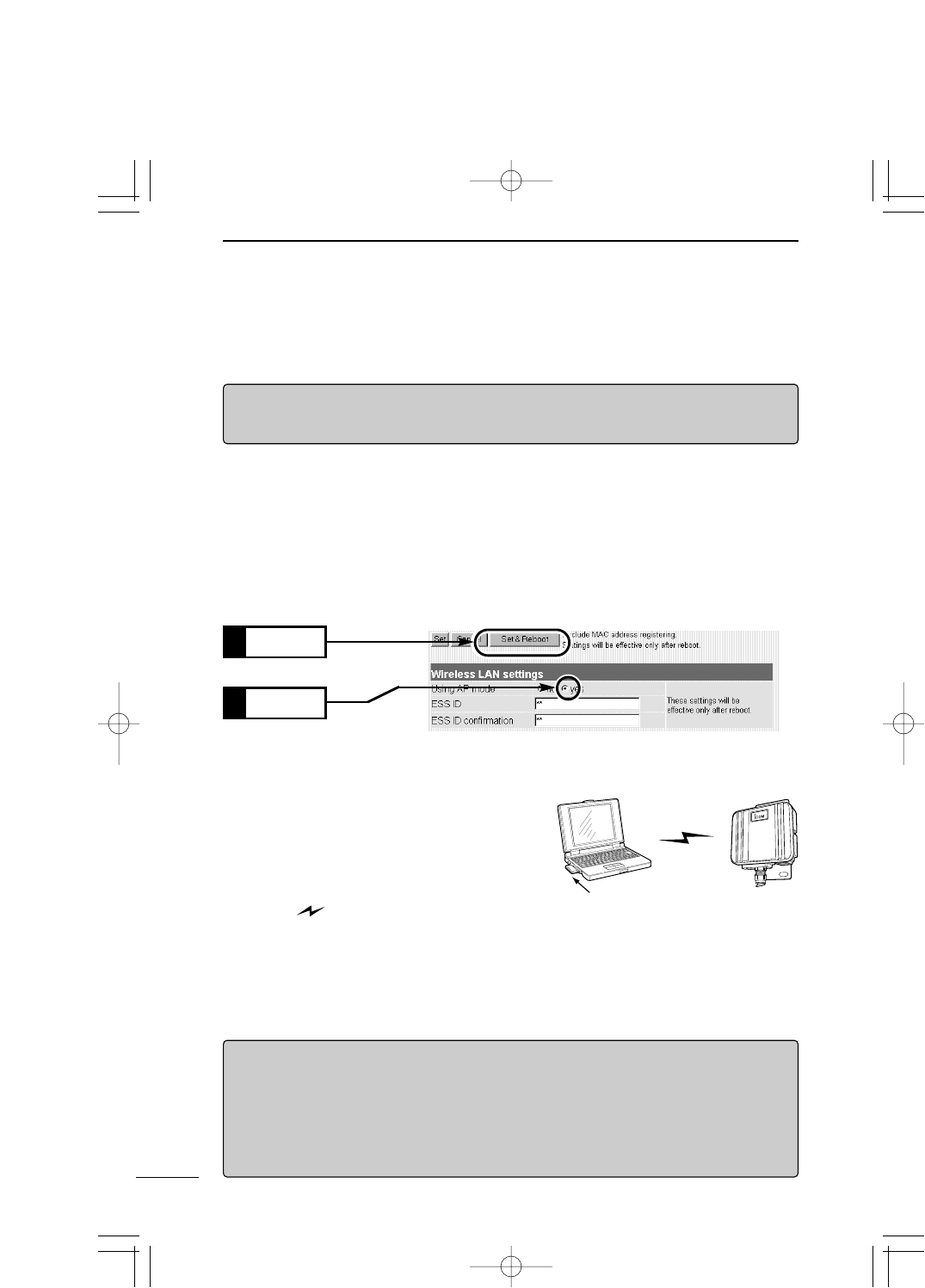
4-3 Changing Wireless Communication Mode
When you use SB-110 as an wireless access point, change the setting according to the
procedure below.
3.
SB-110 restarts and operates in the Access Point mode.
4.
Prepare a PC to which you want to mount our wireless LAN card.
5. This PC must be configured according to the
description of "Connecting through Wireless Ac-
cess Point" (☞see 3-2). When you start the
PC, the IP address is obtained from SB-110 au-
tomatically.
¡The [ ] indicator of SB-110 turns on in
red.
6. Specify "http://192.168.0.1" (default setting). This is URL of SB-110.
¡The [Wireless LAN Settings] screen is shown.
Click
2.
Click
1.
【Wireless Access Point Mode】
If you change the SB-110 setting so that the Routing mode (☞see 5-3)is enabled in ad-
vance, URL to show the setting screen of SB-110 which operates in the Wireless Ac-
cess Point mode is as follows:
¡Wired terminal: http://192.168.0.1 (default setting)
¡Wireless terminal: http://192.168.1.1 (default setting)
【RRemarks】
Wireless communication to Macintosh is unavailable.
Before making the wireless connection, turn on SB-110.
<How to change>
1.
Access the SB-110 setting screen according to the procedure described in 4-1 and 4-2.
¡The [Wireless LAN Settings] screen is shown.
2. Operate as follows:
The default value of any other items should not be changed.
* ESS ID of SB-110 is set to "LG" (upper case, falf size) as a default value. Check
ESS ID of your wireless LAN card before connecting SB-110.
Wireless Communication
LAN Card
Wireless terminal SB-110
PDF取説-E_1 02.1.23 10:28 ページ36
37
SETTING SB-110 4
4
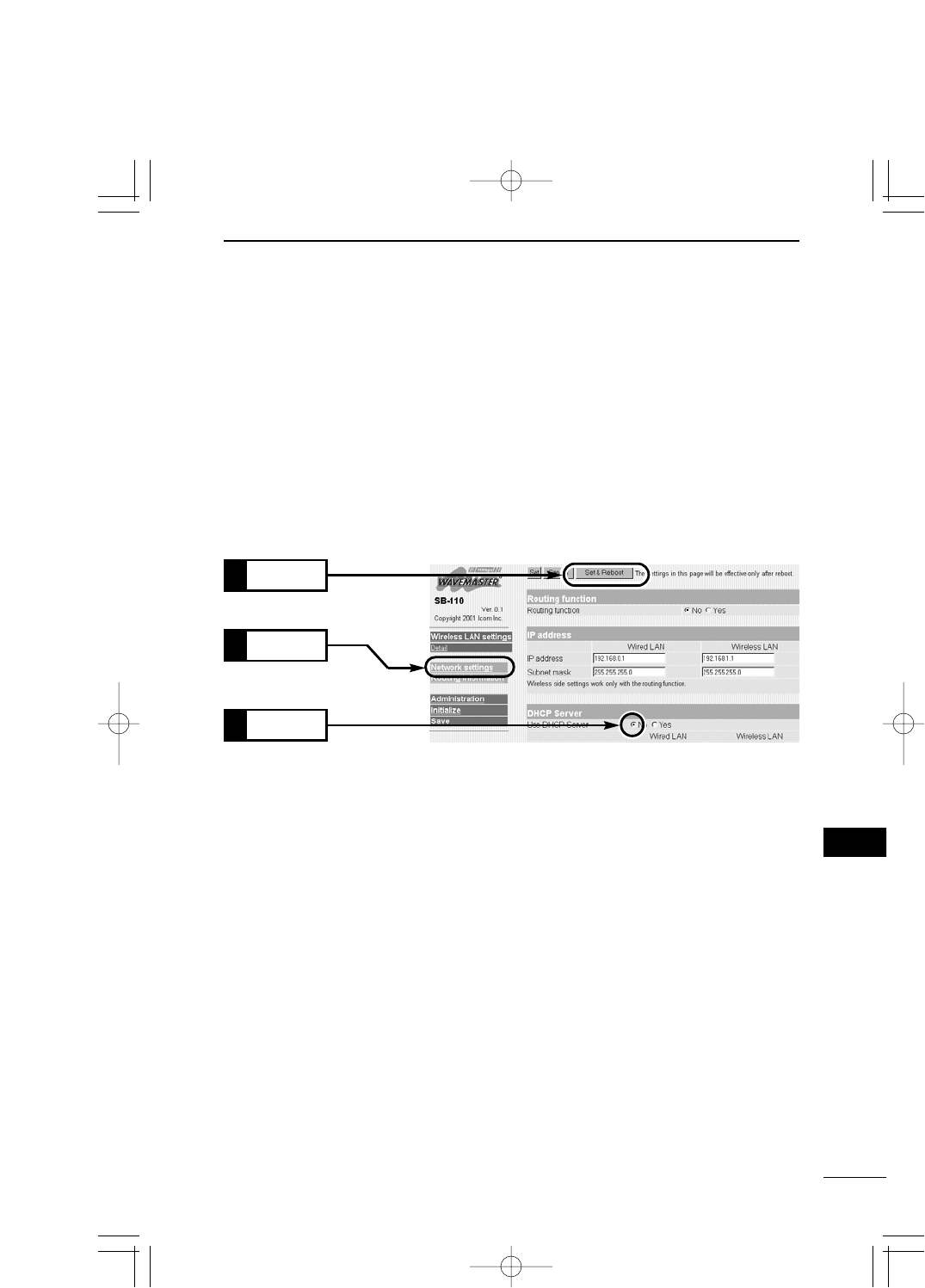
4-4 Stopping DHCP Server
When you connect to any existing network which operates with the DHCP server function,
you need to stop the DHCP server of SB-110 depending on your network environment.
<How to stop>
1.
Access the SB-110 setting screen according to the procedure described in 4-1 and 4-2.
¡The [Wireless LAN Settings] screen is shown.
2. Click [IP address] in the left frame.
¡The [IP address] screen is shown.
3. Click the [No] radio button in the [Use DHCP Server] field in the [DHCP Server] (in the
right frame). Then, click [Set & Reboot].
¡"Now rebooting" is displayed on the screen and the specified details are enabled.
Click
3.
Click
1.
Click
2.
4. Change the IP address of SB-110 and of PC according to the IP address assignment
specified in an existing network (☞see 4-5) and then restart the system.
PDF取説-E_1 02.1.23 10:28 ページ37
38
SETTING SB-110
4
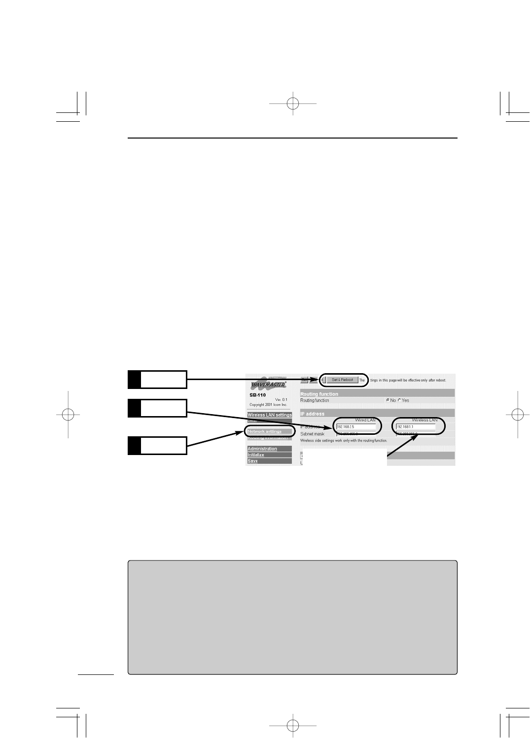
4-5 Changing IP Address Of SB-110
If SB-110 is used in the default setting when you connect an existing LAN, the IP address
of SB-110 may be the same as that assigned to an existing network device. This section
describes how to change the IP address of SB-110.
*
When you change the network section of the IP address, if the DHCP server of SB-110 is
enabled, you need to change also the network section of the automatic assignment start IP
address referring "Changing Automatic Assignment Start IP Address" (☞see 5-9).
<How to change.
1.
Access the SB-110 setting screen according to the procedure described in 4-1 and 4-2.
¡The [Wireless LAN Settings] screen is shown.
2. Click [IP address] in the left frame.
¡The [IP address] screen is shown.
3. Change the IP address of SB-110 and click [Set & Reboot].
¡"The IP address has been changed. Change the computer setting." is displayed on
the screen.
4. If the DHCP server function of SB-110 is enabled, obtain the IP address again using
"winipcfg.exe" (
☞
see 3-4) or restart the PC. If the IP address is assigned to the PC
manually, change the IP address of the network section of such PC according to that of
SB-110
【How to Assign IP Address】
The IP address consists of two elements, i.e., the network section and host section. For "192.168.0.1"
(Class C) which is the default IP address of SB-110, the first part "192.168.0" is the network section and the
second one "1" is the host section. Any network devices (e.g., PC etc.) which have the same network sec-
tion are presumed to be on the same network. Every network device on the same network is identified by
the host section.
So, when you assign the IP address, consider the following rules:
¡Every network device located on the same network must have the same network section.
¡Every network devices be located on the same network must have the unique host section.
¡Do not assign any network address (the first position of the host section, "0").
¡Do not assign any broadcast address (the last position of the host section, "255").
Change
2.
Click
1. Not need to be changed
unless routing mode is
used.
Click
3.
PDF取説-E_1 02.1.23 10:28 ページ38
39
SETTING SB-110 4
4
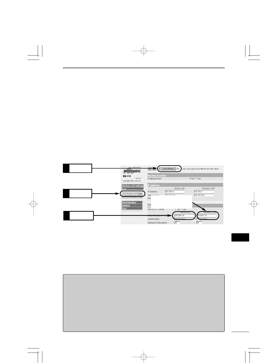
4-6 Changing Automatic Assignment Start IP Address
If the network section of the IP address of SB-110 is changed to enable the DHCP server
function of SB-110, the network section of the automatic assignment start IP address also
must be changed. This section describes how to change the automatic assignment start IP
address.
<How to change>
1.
Access the SB-110 setting screen according to the procedure described in 4-1 and 4-2.
¡The [Wireless LAN Settings] screen is shown.
2. Click [IP address] in the left frame.
¡The [IP address] screen is shown.
3. Change the automatic assignment start IP address and click [Set & Reboot].
¡"Now rebooting" is displayed on the screen and the specified details are enabled.
【DHCP Server Function】
If the DHCP server function of SB-110 is enabled (the default setting), the IP address can be obtained from
SB-110 automatically when a PC has been connected to SB-110.
When you connect SB-110 to an existing LAN, the IP address assigned by SB-110 must be different from
the fixed IP address assigned to any existing network device (e.g., PC etc). Moreover, the network section
must be the same as that of the IP address of SB-110.
【The Number of IP Addresses Assigned Automatically】
The number of IP address assigned by SB-110 automatically is 5 to 128. For the default assignment start
IP address and subnet mask set value, the maximum number of IP addresses which can be assigned log-
ically is 254. However, if you assign 128 addresses or more, those addresses should be assigned to the
clients manually.
Click
1. Not need to be changed
unless routing mode is
used.
Change
2.
4. If the DHCP server function of SB-110 is enabled, obtain the IP address again using
"winipcfg.exe" (
☞
see 3-4) or restart the PC.
Click
3.
PDF取説-E_1 02.1.23 10:28 ページ39

PDF取説-E_1 02.1.23 10:28 ページ40

CHAPTER 5
SETTING SCREEN
5-1. [Wireless LAN settings] Screen ……………………………………………………42
■Wireless LAN setting ……………………………………………………………42
■MAC Address security setting …………………………………………………43
5-2 [Detail settings] Screen ……………………………………………………………45
■Detail settings ……………………………………………………………………45
■Custom Security …………………………………………………………………47
■Hidden Terminal …………………………………………………………………50
■Relation between [Security Level] and [Custom Security] …………………51
■[Security Level] Setting …………………………………………………………51
■Example of [WEP Key] Setting …………………………………………………52
5-3 [IP address] Screen …………………………………………………………………53
■Routing function …………………………………………………………………53
■IP address…………………………………………………………………………54
■DHCP Server ……………………………………………………………………55
■Static DHCP Server ……………………………………………………………58
5-4 [Routing function] Screen …………………………………………………………59
■RIP …………………………………………………………………………………59
■Network Interface List ……………………………………………………………59
■IP Routing Information …………………………………………………………60
■Static Route ………………………………………………………………………61
5-5 [Administration] Screen ……………………………………………………………62
■Manager ID ………………………………………………………………………62
■SYSLOG …………………………………………………………………………63
■Use utility (Firmware Update Mode)……………………………………………64
This chapter describes every item in the SB-110 setting screen.
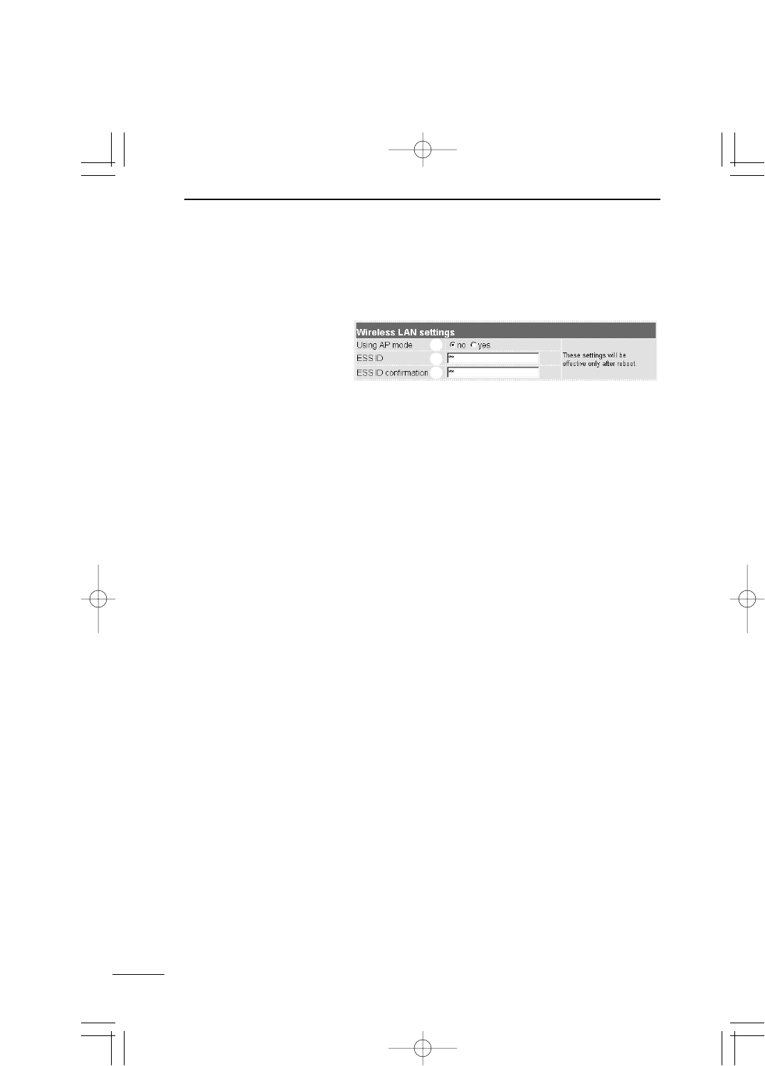
5-1 [Wireless LAN settings] Screen
■Wireless LAN setting
42
SETTING SCREEN
5
Select a wireless communication mode (default setting: no).
¡[no]:Select for the Building Communication (Bridge) mode.
¡[yes]:Select for the Access Point mode.
Enter an ID to prevent an unauthorized access to the wire-
less LAN connected to SB-110. This ID is case-sensitive.
Enter a maximum of 31 alphanumeric characters (default
ID: LG).
The entered characters are all expressed as a asterisk
(e.g., **).
In the Building Communication mode (
☞
see 1-3), several
SB-110s with the same [ESS] ID can be connected to
each others by wireless. In the Access Point mode (☞
see 1-4), SB-110 and a wireless terminal can be con-
nected by wireless.
To enable the changed settings, you need to reboot SB-
110.
To prevent an error in typing the ID, enter the [ESS ID] again
in this field. Please note that the ID is case-sensitive.
(The entered ID is expressed as a asterisk, e.g., **.)
qUsing AP mode……
wESS ID ………………
eESS ID confirmation…
q
w
e
Setting for wireless section of SB-110.
PDF取説-E_1 02.1.23 10:28 ページ42
43
SETTING SCREEN 5
5
5-1 [Wireless LAN settings] Screen (continued from the previous page)
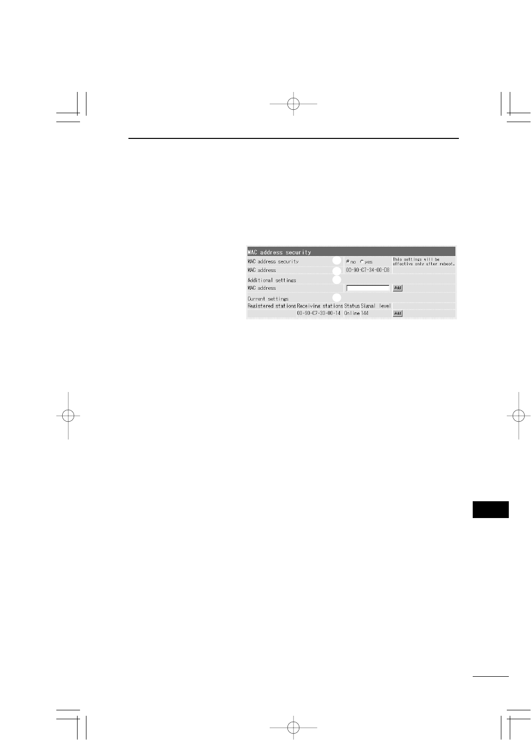
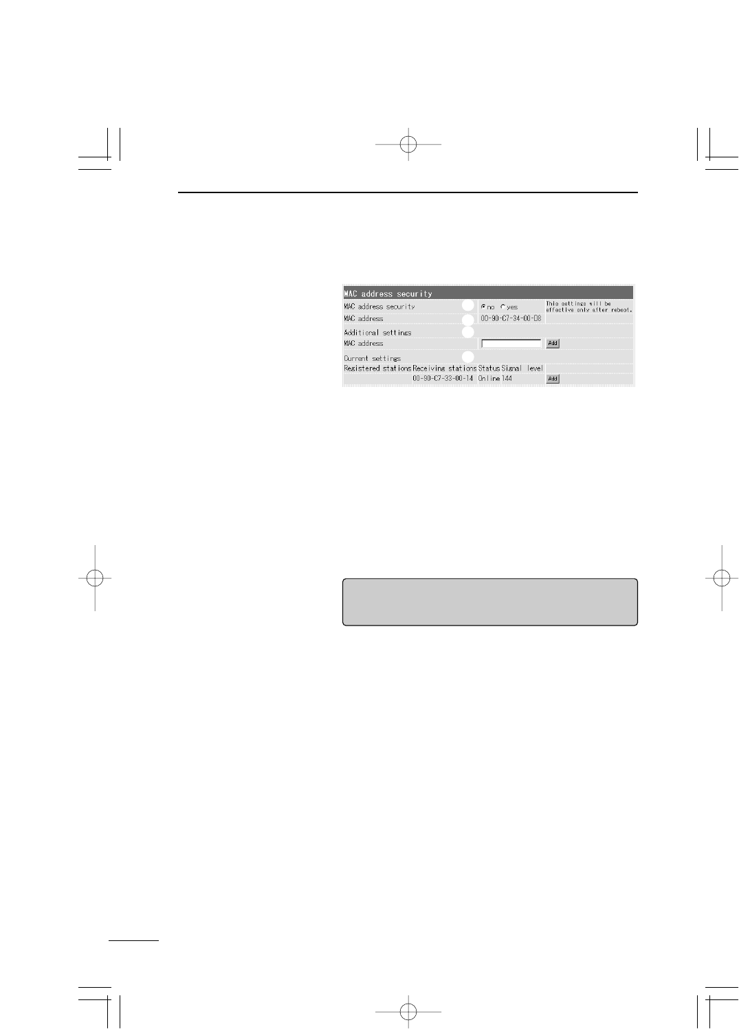
■MAC Address security setting
Register the MAC address display of SB-110 and the
MAC address of device to be connected by wireless
and restrict the connection.
Specify whether only SB-110 with the same MAC address
as one registered in advance or wireless terminal with
such same MAC address can be connected to SB-110 or
not (default setting: no).
* To enable the setting change, click [Set & Reboot].
The MAC address registered in the wireless section of SB-
110 is displayed here. This MAC address is also the MAC
address of SB-110.
* If any address is displayed here, please contact the
shop or our service section.
Enter the MAC address of target SB-110 or wireless ter-
minal in this field.
* A maximum of 256 MAC addresses can be registered.
* A maximum of 12 characters (falf size) can be entered.
* When you have enter the MAC address, click [Add] to
check that the address has been registered in the [Cur-
rent settings] field.
* The following two types of character strings are consid-
ered as the same address.
11-11-11-22-33-33, 1111112233
qMac address
security ……………
wMAC address………
eAdditional settings
q
w
e
r
PDF取説-E_1 02.1.23 10:28 ページ43
44
SETTING SCREEN
5
5-1 [Wireless LAN settings] Screen
■MAC Address security setting (continued from the previous page)
The status of device communicating to SB-110 by wire-
less and the MAC address of registered wireless commu-
nication device are displayed here (default setting: no).
Any registered MAC address can be deleted by [Delete].
If the MAC address displayed in the [Receiving stations]
field is not registered, it can be registered by clicking
[Add].
* If a numerical value 110 to 200 is displayed in the [Sig-
nal level] field, the communication status is good.
rCurrent settings …
q
w
e
r
【RRemarks】
Wireless communication to Macintosh is unavailable.
Before making the wireless connection, turn on SB-110.
PDF取説-E_1 02.1.23 10:28 ページ44
45
SETTING SCREEN 5
5
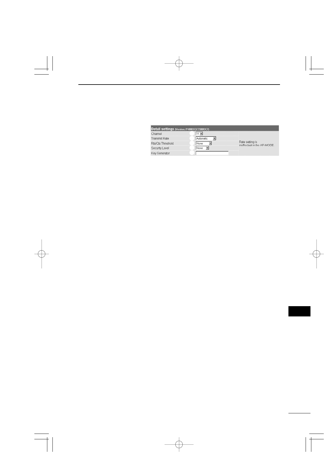
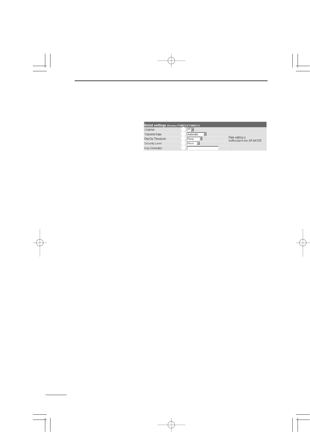
5-2 [Detail settings] Screen
■Detail settings
Specify a channel to be used for the wireless communica-
tion of SB-110 (default setting: 11).
* If several SB-110s are communicated to each other in
the Building Communication mode (☞see 1-3), specify
the same value for those SB-110s.
* A wireless terminal which communicates to our 11 Mbps
wireless LAN card in the Access Point mode (☞see 1-4)
detects the channel of SB-110 automatically when com-
municating.
Specify the wireless transmission rate in the Building
Communication mode (default setting: Automatic).
This setting is disabled in the Access Point mode.
* Regardless of this setting, any data can be received in
the wireless transmission rate of 1 to 11 Mbps.
Specify "500 bytes" or "1000 bytes" as the size of packet
sent for negotiation (default setting: None).
When the Rts/Cts (Request to send/Clear to send)
Threshold is set, the decrease in communication speed
can be prevented due to the influence of the hidden ter-
minal (☞see page 50).
qChannel ……………
wTransmit Rate ……
eRts/Cts Threshold
Specify the details of the wireless section of SB-110.
q
w
e
r
t
PDF取説-E_1 02.1.23 10:28 ページ45
46
SETTING SCREEN
5
5-2 [Detail settings] Screen
■Detail settings (continued from the previous page)
Specify the percentage to encrypt a data sent through the
wireless LAN to protect the data (Default setting: None).
WEP (Wired Equivalent Privacy) is used as the encryption
method. Except [WEP Key], all the items in [Custom Se-
curity] are set automatically according to the security level
(Low, Middle or High) specified here. When "Custom" is
selected, all the items displayed in [Custom Security] can
be specified manually. [WEP Key] can be specified man-
ually always.
* It is advisable to set the same security level for all the
communicating devices.
Specify a character string to generate a key used for en-
cryption and decryption. The entered characters are all
expressed as a asterisk (e.g., **).
After the registration, a key generated by the entered
character string is displayed in the WEP key text box in
[Custom Security].
* Set the same character string (alphanumeric characters
or symbols which are case-sensitive) for all the devices
in communication. If different character string is set for
all the communicating devices, the encrypted data can-
not be decrypted.
rSecurity Level ……
tKey Generator ……
q
w
e
r
t
PDF取説-E_1 02.1.23 10:28 ページ46
47
SETTING SCREEN 5
5
5-2 [Detail settings] Screen (continued from the previous page)
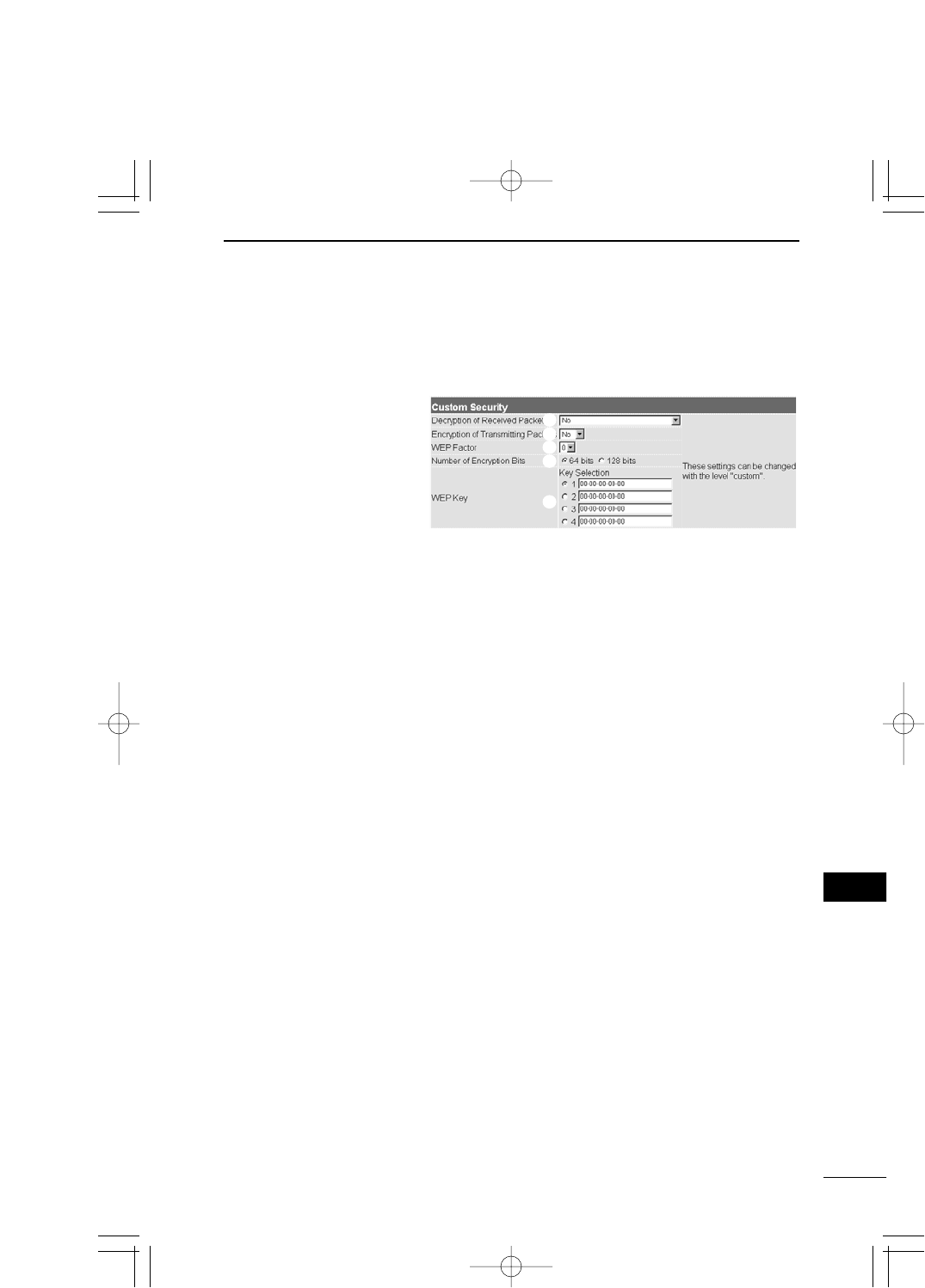
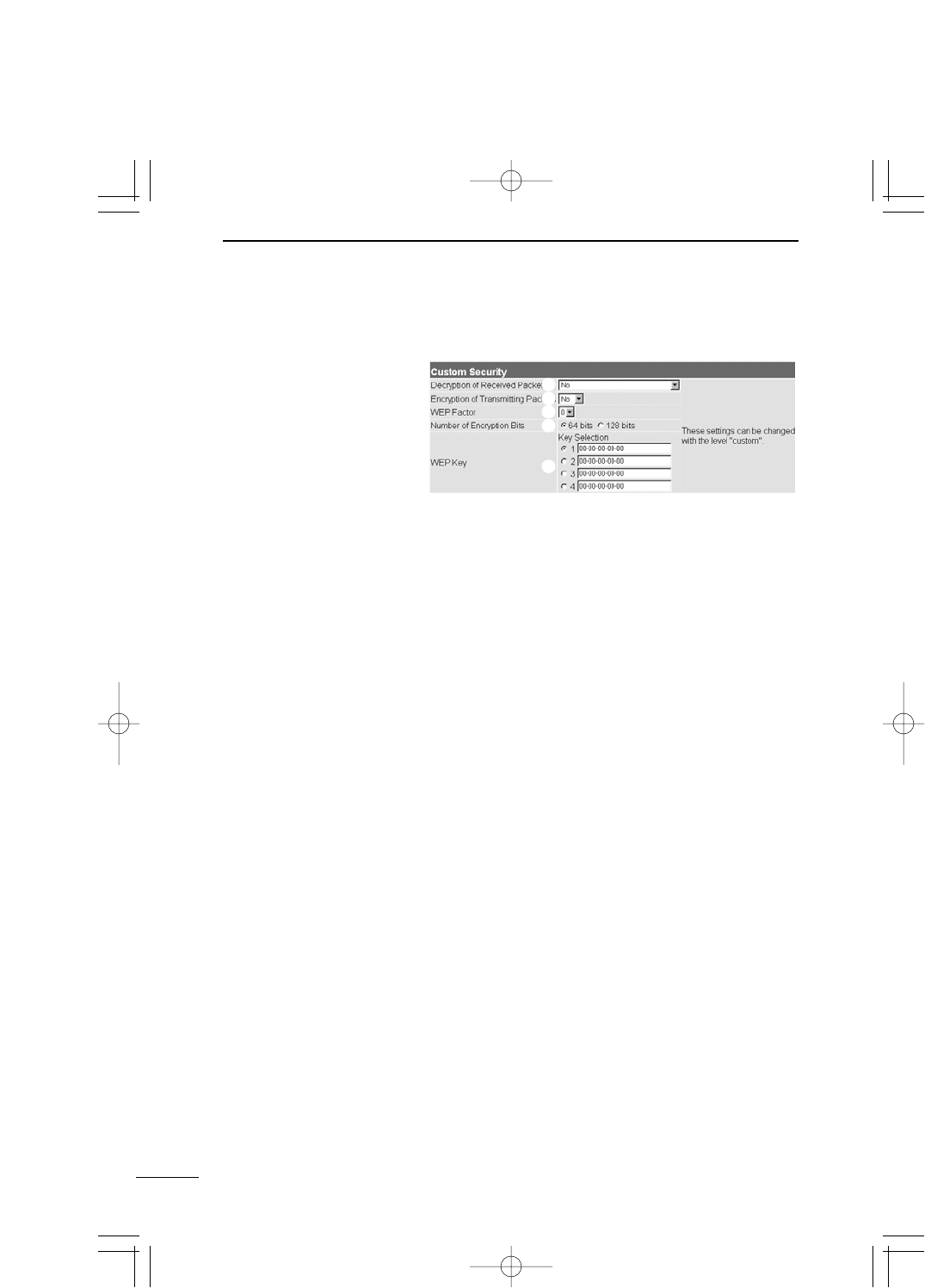
■Custom Security
Setting for decryption of received packet. Select any of
"Yes", "No" and "Yes (Abandon any packet not en-
crypted)" (default setting: No).
Setting for encryption of transmitting packet. Select "Yes"
or "No" (default setting: No).
Item to specify a security level. The value [0] means the
highest security level (initial value: 0). The values means
as follows:
[0] = Changes an internal encryption key per packet.
[1] = Changes an internal encryption key at every 10 packets.
[2] = Changes an internal encryption key at every 50 packets.
[3] = Changes an internal encryption key at every 100 pack-
ets.
qDecryption of
Received Packet …
wEncryption of
Transmitting Packet
eWER Factor ………
Specify the items (except [WEP Key]) below when
"Customs" is selected in [Security Level] of [Detail
Setting].
q
w
e
r
t
PDF取説-E_1 02.1.23 10:28 ページ47
48
SETTING SCREEN
5
5-2 [Detail settings] Screen
■Custom Security (continued from the previous page)
Specify the number of bits which encrypt the character
string entered in [Key Generator] of [Detail Settings] (de-
fault setting: 64 bits).
When you select "64 bits", the low-order 40 bits (10-digit
hexadecimal number of ) of the key generated by the
character string entered in [Key Generator] are displayed
in the [WEP Key] text box. Otherwise, you may enter a
hexadecimal number within 10 digits in this text box di-
rectly.
When you select "128 bits", the low-order 104 bits are dis-
played in the [WEP Key] text box. Otherwise, you may
enter a hexadecimal number within 26 digits in this text
box directly.
* When you enter the value in the [WEP Key] text box di-
rectly, such value is not displayed in the
[Key Generator] text box. Also, the first 24 bits are
never displayed.
rNumber of
Encryption Bits……
q
w
e
r
t
PDF取説-E_1 02.1.23 10:28 ページ48

49
SETTING SCREEN 5
5
5-2 [Detail settings] Screen
■Custom Security (continued from the previous page)
Specify a key and character string used for encryption (de-
fault setting: 1).
To encrypt data, use the alphanumeric characters of hexa-
decimal notation displayed in the checked [Key Selection]
text box. The other party can decrypt the encrypted data
(receive it correctly) only when the same alphanumeric
characters of hexadecimal notation are displayed in any
of text boxes next to the [Selection (Key)] numbers (1 to
4).
In each text box, enter directly a key (alphanumeric char-
acters) of hexadecimal notation used for encryption and
decryption by the other communication party. If the [Num-
ber of Encryption Bits] settings of the communicating de-
vices are different from each others or if the contents of
the text boxes of those communicating devices, which are
used for the encryption and decryption, are different from
each other, no communication can be made.
It is advisable to apply the same settings to all the text
boxes of the communicating devices. If the contents of
those text box are the same, the communication can be
made between them even when their key numbers are dif-
ferent from each others.
* You may enter data in each text box next to the [WEP
Key], instead of the text box of [Key Generator] of [Detail
Settings]. (In this case, any character string is not dis-
played in the text box of [Key Generator].)
* For an example of setting, refer to page 52.
tWEP Key……………
PDF取説-E_1 02.1.23 10:28 ページ49
5-2 [Detail settings] Screen (continued from the previous page)
■Hidden Terminal
50
SETTING SCREEN
5
A
Communication
Collision
SB-110 [B]
Radio Transmission Area
SB-110 [B]
Radio Transmission Area
Wireless terminal [A]
Radio Transmission Area
Wireless terminal [C]
Radio Transmission Area
C
B
Wireless terminal [A]
Radio Transmission Area
Wireless terminal [C]
Radio Transmission Area
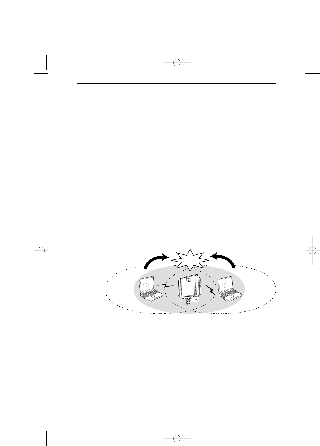
For the communication in the Access Point mode, as
shown below, even if the terminals [A] and [C] can com-
municate with SB-110 [B], those terminals [A] and [C] can-
not communicate with each other. In this case, the termi-
nal [A] is referred to as "Hidden Terminal" to [C] and the
terminal [C] is also referred to as "Hidden Terminal" to [A].
If there is any hidden terminal, the carrier sense does not
function effectively to those wireless terminals. So, com-
munication collision happens frequently in SB-110 [B] and
the throughput (the amount of information transmitted
within a specified period) decreases.
To prevent the communication collision, SB-110 [B] which
received the request-to-send (Rts) signal sends the Clear-
to-send (Cts) signal repeatedly to the wireless terminals
[A] and [C]. Then, either of those two wireless terminals,
which does not send Rts, can recognize that SB-110 [B] is
communicating with the hidden terminal.
Now, the wireless terminal [A] or [C] , which does not send
Rts, forbears the access to SB-110 [B] and the communi-
cation collision can be prevented.
PDF取説-E_1 02.1.23 10:28 ページ50
51
SETTING SCREEN 5
5
5-2 [Detail settings] Screen (continued from the previous page)
■Relation between [Security Level] and [Custom Security]
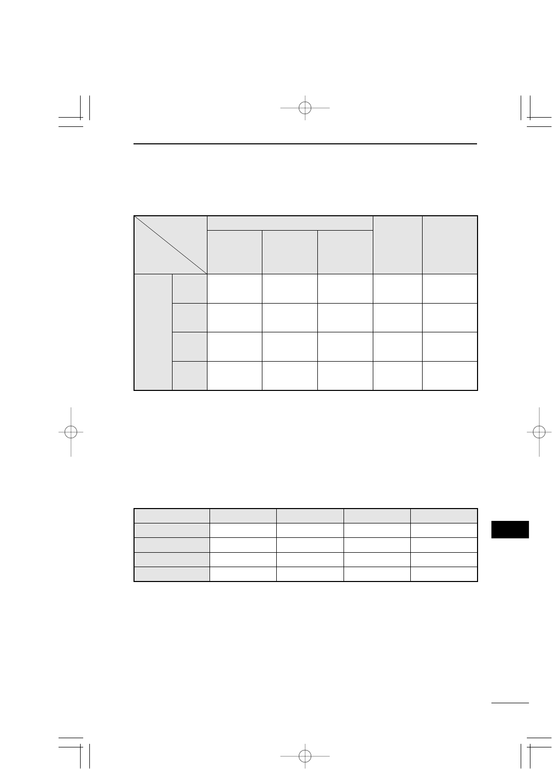
■[Security Level] Setting
The table below shows the security level available for the communication between the ter-
minals in which the security level is set.
(○: Communication can be made. ×: No communication can be made.)
* If the character string of [Key Generator] of communicating devices is different from each
others, no communication can be made even if the security level is the same.
WEP Setting
WEP
Factor
Number of
Encryption
Bits
Decrypt
received
packet
Abandon any
packet not
encrypted
Encrypt
transmitting
packet
Security
Level
No Not decrypt Setting
disabled Not encrypt Disabled Disabled
Low Decrypt Not abandon Encrypt 3 64-bit
encryption
Middle Decrypt Abandon Encrypt 0 64-bit
encryption
High Decrypt Abandon Encrypt 0 128-bit
encryption
Security Level No Low Middle High
No ○×××
Low ×○○×
Middle ×○○×
High ×××○
PDF取説-E_1 02.1.23 10:28 ページ51
52
SETTING SCREEN
5
5-2 [Detail settings] Screen (continued from the previous page)
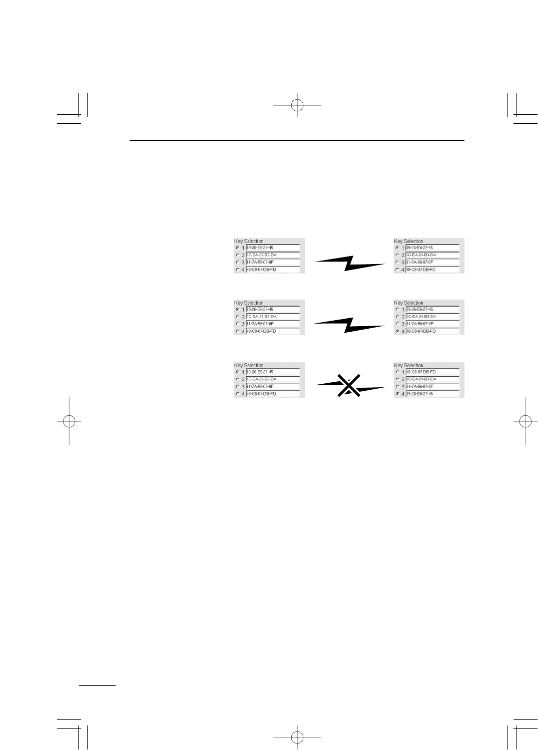
■Example of [WEP Key] Setting
When the WEP key is set for 64-bit encryption:
Communication
unavailable
Two-way
communication
available
Two-way
communication
available
PDF取説-E_1 02.1.23 10:28 ページ52
53
SETTING SCREEN 5
5
5-3 [IP address] Screen
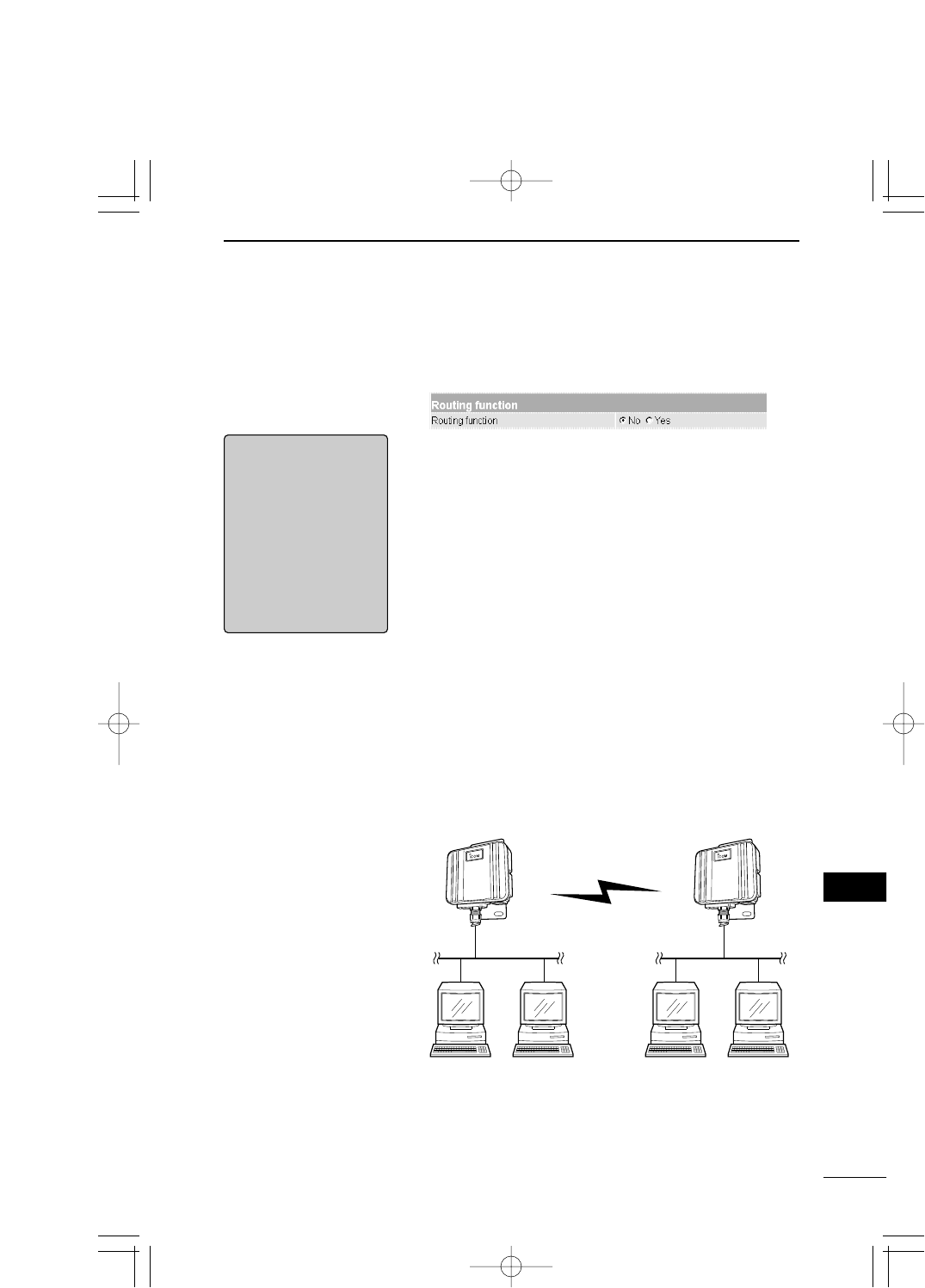
■Routing function Item to be set when connecting every communicating
network through a different IP address of the network
section.
Specify whether a routing function between a wired LAN
and wireless LAN is enabled or disabled (default setting:
No, i.e., disable).
Available protocol is TCP/IP only.
To enable the changed setting, you need to restart SB-110.
If the routing mode is used, traffic of unnecessary broad-
cast can be minimized when communication is made.
* When you select "No", you can set the IP address of the
same network section between the wired LAN and wire-
less LAN.
* When you select "Yes", you can set the IP address of a
different network section between the wired LAN and
wireless LAN.
[RRemarks]
If the routing mode is
used in the Access
Point mode, any wire-
less terminal cannot be
used for roaming be-
cause every device
(SB-110) has its own
unique network ad-
dress.
■Conceptual Diagram
An upper part of the diagram shows an example of the ad-
dress of each network when routing is not used. A lower
part of the diagram shows an example of the address of
each network when routing is used.
No (Disable): 192.168.0.0
Yes (Enable): 192.168.1.0
No (Disable): 192.168.0.0
Yes (Enable): 192.168.0.0
No (Disable): 192.168.0.0
Yes (Enable): 192.168.2.0
PDF取説-E_1 02.1.23 10:28 ページ53
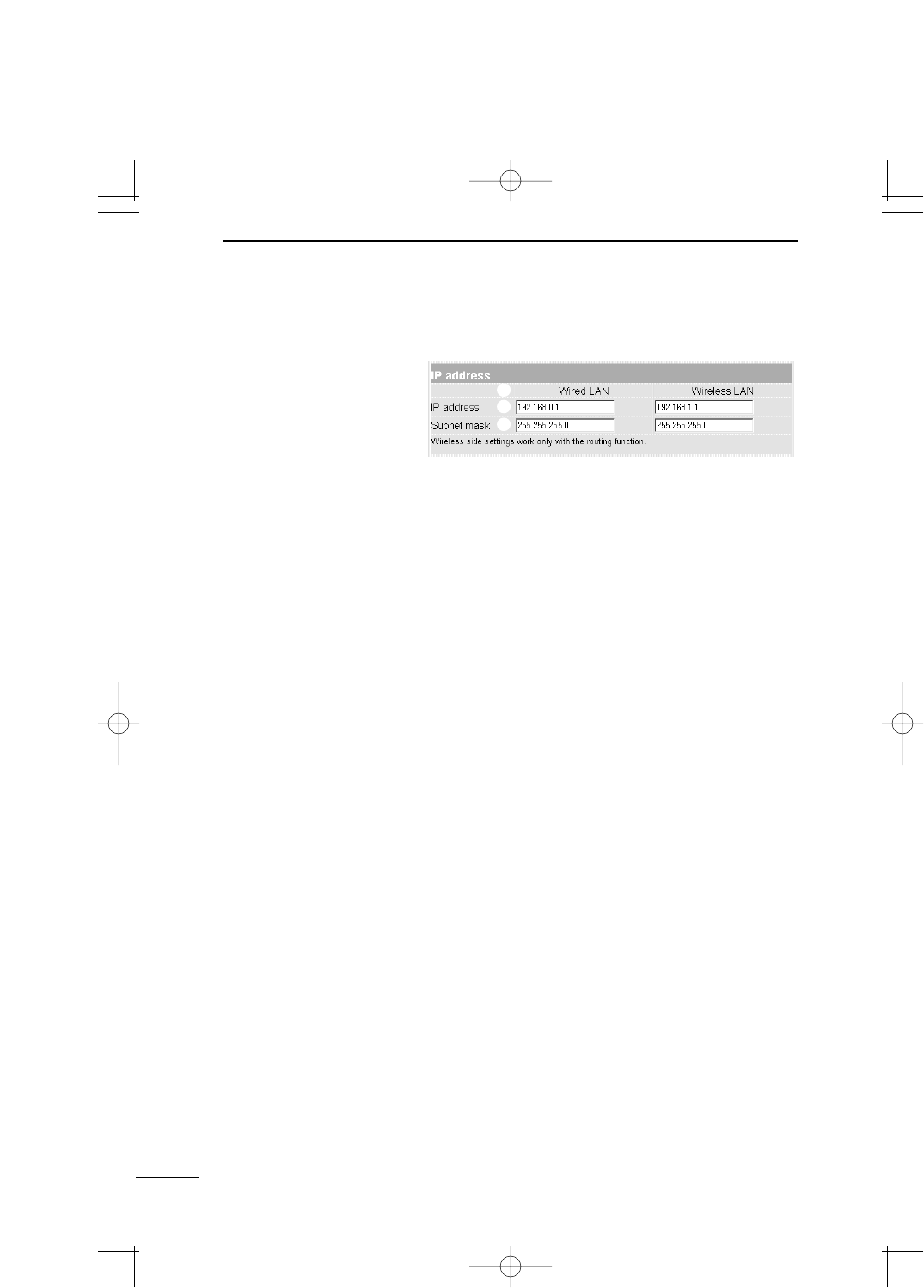
5-3 [IP address] Screen (continued from the previous page)
■IP address
54
SETTING SCREEN
5
qWired LAN /
Wireless LAN………
wIP address …………
eSubnet mask ………
The IP address and subnet mask set in the wired LAN
are enabled only when the [Yes] radio button of [Rout-
ing function] is checked. If the [No] radio button of
[Routing function] is checked (default setting), the IP ad-
dress and subnet mask set in the wired LAN apply to the
wireless LAN also.
Specify the IP address of wires LAN and wireless LAN of
SB-110.
To enable the changed setting, you need to restart SB-110.
◎Wired LAN: 192.168.0.1 (default setting)
◎Wireless LAN: 192.168.1.1 (default setting)
Specify the subnet mask of wires LAN and wireless LAN
of SB-110.
To enable the changed setting, you need to restart SB-110.
◎Wired LAN: 255.255.255.0 (default setting)
◎Wireless LAN: 255.255.255.0 (default setting)
q
w
e
Setting for the IP address and subnet mask of SB-110.
PDF取説-E_1 02.1.23 10:28 ページ54
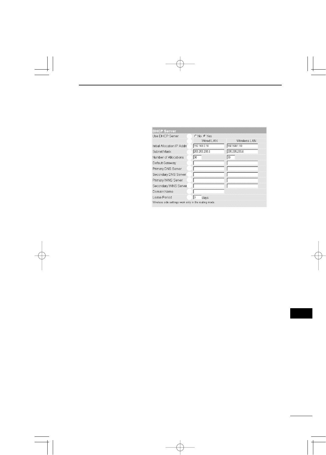
5-3 [IP address] Screen (continued from the previous page)
■DHCP Server
55
SETTING SCREEN 5
5
qUse DHCP Server …
wWired LAN /
Wireless LAN………
eInitial Allocation IP
Address ……………
Specify whether SB-110 is used as the DHCP server or
not (default setting: Yes).
If TCP/IP of PCs connected to SB-110 through cable or
by wireless is set to [Obtain an IP address automatically],
those PCs become the DHCP client of SB-110. By this
function, the IP address/subnet mask and the IP ad-
dress/domain name of router and DNS server obtained
dynamically from SB-110 which is the DHCP server.
Every item set in the wired LAN in the [DHCP Server]
screen is enabled only when the [Yes] radio button of
[Routing function] is checked. If the [No] radio button of
[Routing function] is checked (default setting), the values
set in the wired LAN apply to the wireless LAN also.
Specify the initial IP address allocated automatically to the
clients connected directly to SB-110 through cable or by
wireless.
◎Wired LAN: 192.168.0.10 (default setting)
◎Wireless LAN: 192.168.1.10 (default setting)
q
w
e
r
t
y
u
i
o
!0
!1
!2
Setting for the DHCP server function of SB-110.
PDF取説-E_1 02.1.23 10:28 ページ55
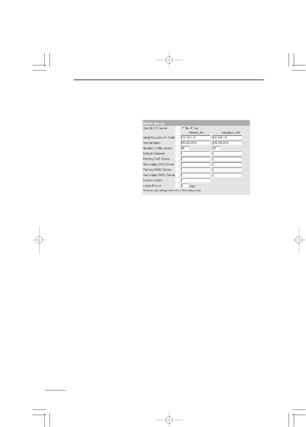
56
SETTING SCREEN
5
5-3 [IP address] Screen
■DHCP Server (continued from the previous page)
rSubnet Mask ………
tNumber of Alloca-
tions…………………
yDefault Gateway …
uPrimary DNS Server
Subnet mask to [Initial Allocation IP Address].
◎Wired LAN: 255.255.255.0 (default setting)
◎Wireless LAN: 255.255.255.0 (default setting)
The maximum number of addresses which can be as-
signed continuously from the IP address specified in [Initial
Allocation IP Address] is 5 to 128 (default setting: 30).
For the default set value of [Initial Allocation IP Address]
and [Subnet Mask], the maximum number of IP addresses
which can be assigned logically is 254. However, if you
assign 128 addresses or more, those addresses should
be assigned to the clients manually.
Default gateway noticed to a client.
When the [Yes] radio button of [Use DHCP Server] is
checked, if there are two DNS server addresses, enter the
either one in this field as necessary. Instead of the IP ad-
dress of SB-110, the entered DNS server address is no-
ticed to the DHCP client.
q
w
e
r
t
y
u
i
o
!0
!1
!2
PDF取説-E_1 02.1.23 10:28 ページ56

57
SETTING SCREEN 5
5
5-3 [IP address] Screen
■DHCP Server (continued from the previous page)
iSecondary DNS
Server ………………
oPrimary WINS
Server ………………
!0 Secondary WINS
Server ………………
!1 Domain Name ……
!2 Lease Period ………
Similarly with [Primary DNS Server] above, enter the ei-
ther of the two DNS server address in this field as neces-
sary.
If you use a WINS server in the Microsoft network, enter
the WINS server address in this field. If there are two
WINS server addresses, enter the either one as neces-
sary.
Similarly with [Primary WINS Server] above, if there are
two WINS server addresses, enter the either one in this
field as necessary.
Enter a domain name of a network address noticed to a
client by the DHCP server, when the domain name is used
for Ethernet, if necessary.
Enter the number of days (1 to 99) as intervals that the
DHCP server updates the local IP address of client auto-
matically and periodically (default setting: 3).
q
w
e
r
t
y
u
i
o
!0
!1
!2
PDF取説-E_1 02.1.23 10:28 ページ57
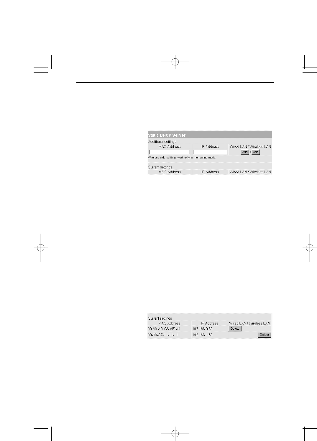
5-3 [IP address] Screen (continued from the previous page)
■Static DHCP Server
58
SETTING SCREEN
5
Field to register the combination of the MAC address and
IP address of a PC when fixing the IP address, which is
assigned automatically using the DHCP server, to a spe-
cific client.
* A maximum of 16 combinations can be registered in this
field. The client IP address to be registered must be out
of the address range assigned by the DHCP server
function.
* To register the details of wired terminal, click [Add] of
[Wired LAN]. To register the details of wireless termi-
nal, click [Add] of [Wireless LAN].
* The registration of wireless terminal is enabled only
when the [Yes] radio button of [Routing function] is
checked.
■Example of Registration
Setting to fix the IP address assigned to a specific
client.
To cancel the registration, click [Delete] in an applicable
field.
When the [Yes] radio but-
ton of [Routing function]
is checked.
PDF取説-E_1 02.1.23 10:28 ページ58
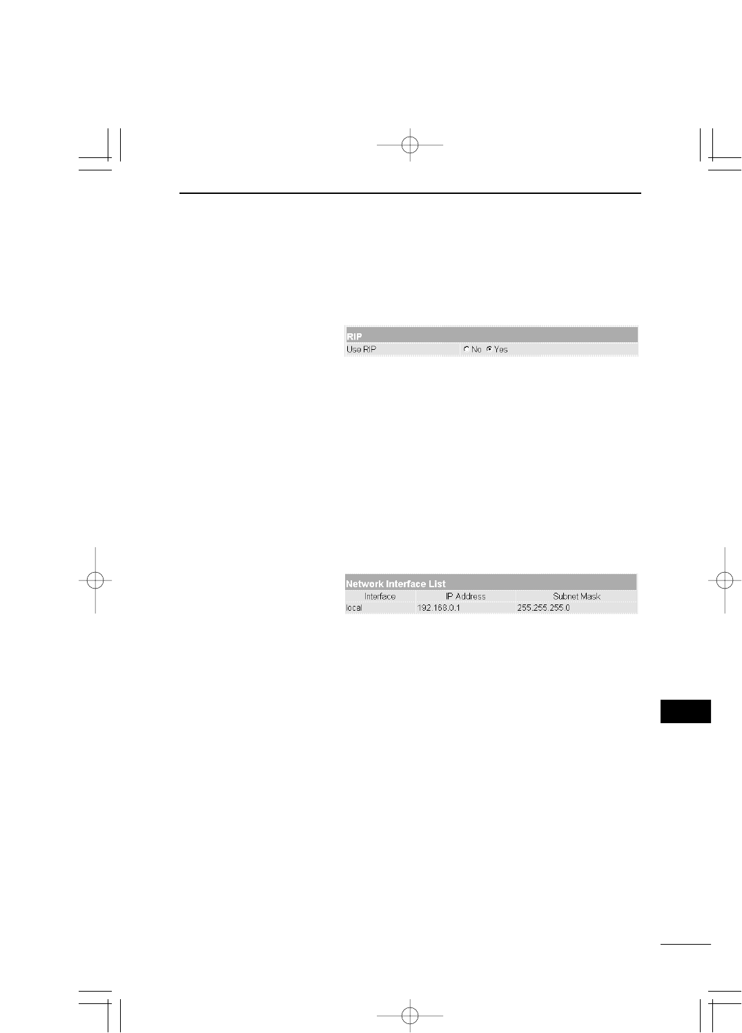
5-4 [Routing function] Screen
■RIP
59
SETTING SCREEN 5
5
Specify whether the RIP function is used or not (default
setting Yes).
When the RIP is used, an RIP packet is broadcasted at
approximately 30 seconds using the broadcast address of
the access point.
* When you have changed this setting, click the [Set &
Reboot] button to enable the change.
■Network Interface List
Refer to the description of [Path] of [IP Routing Informa-
tion] (☞see page 60).
Specify when exchanging routing information with an
adjacent router or access point by using the RIP func-
tion to create a route dynamically.
PDF取説-E_1 02.1.23 10:28 ページ59
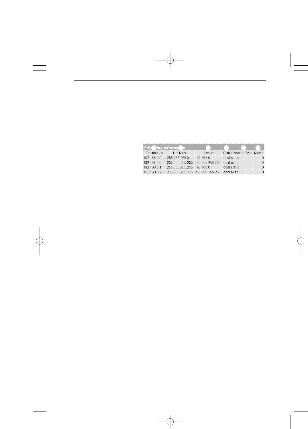
60
SETTING SCREEN
5
5-4 [Routing function] Screen (continued from the previous page)
■IP Routing Information
This screen shows the information about a router or
terminal to which another router sends a packet. The
screen shows a path added in [Static Route] also.
Shows the IP address of destination of packet routing.
Shows the subnet mask to the IP address of destination of
packet routing.
Shows the gateway to the IP address of destination of
packet routing.
Shows the transfer destination interface to the IP address
of destination of packet routing. The details of such inter-
face are shown in the [Network Interface List] screen
(
☞
see page 59).
Shows how routing information was created.
¡static : Created according to a static route (which was de-
fined).
¡rip : Created according to a dynamic route (which was gen-
erated automatically).
¡misc :Created by a frame operation related to broadcast.
Shows the cost of path.
qDestination…………
wSubnet mask ………
eGateway ……………
rPath …………………
tCreation Type ……
yMetric ………………
qw e r t y
PDF取説-E_1 02.1.23 10:28 ページ60
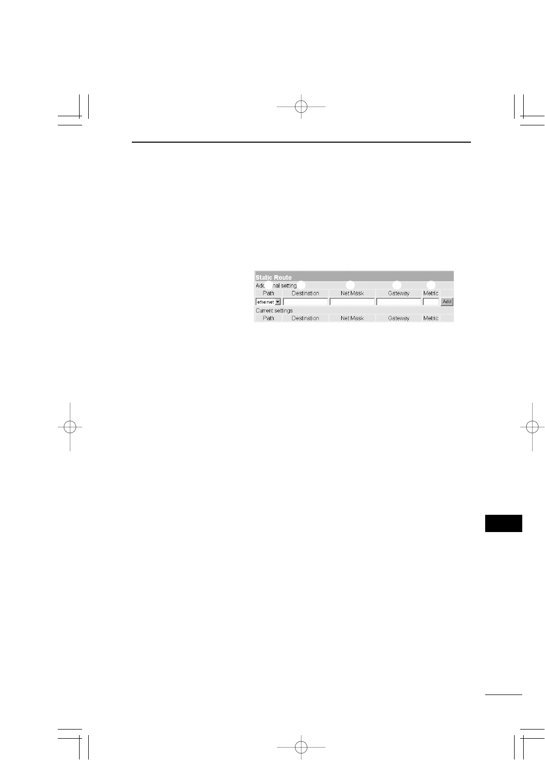
61
SETTING SCREEN 5
5
5-4 [Routing function] Screen (continued from the previous page)
■Static Route Routing table to define a relay path of packet inten-
tionally. A maximum of 20 items can be registered.
* When you have entered data, click [Add] to check that
the data has been registered in the [Current setting]
field. The details of registered data are displayed also in
the [IP Routing Information] screen.
¡local: Shown when the [No] radio button of [Routing
function] is checked. This means that routing in-
formation to be registered is at the LAN side.
¡ethernet: Shown when the [Yes] radio button of [Routing
function] is checked. This means that routing in-
formation to be registered is a wired LAN.
¡wireless: Shown when the [Yes] radio button of [Routing
function] is checked. This means that routing in-
formation to be registered is a wireless LAN.
According to a selected path (local/ethernet/wireless), spec-
ify the IP address of the target party.
According to a selected path (local/ethernet/wireless), spec-
ify the net mask to the IP address of the target party.
Enter a gateway of packet transfer destination (router or ac-
cess point) to be routed.
Specify the number of routers and access points (or gate-
ways) on the route through which a packet is sent to the
other party. Enter a value in a range between 0 and 15. It
is presumed that transmission capacity of a line with a
smaller value is high.
qPath …………………
wDestination…………
eSubnet mask ………
rGateway ……………
tMetric ………………
q w e r t
PDF取説-E_1 02.1.23 10:28 ページ61
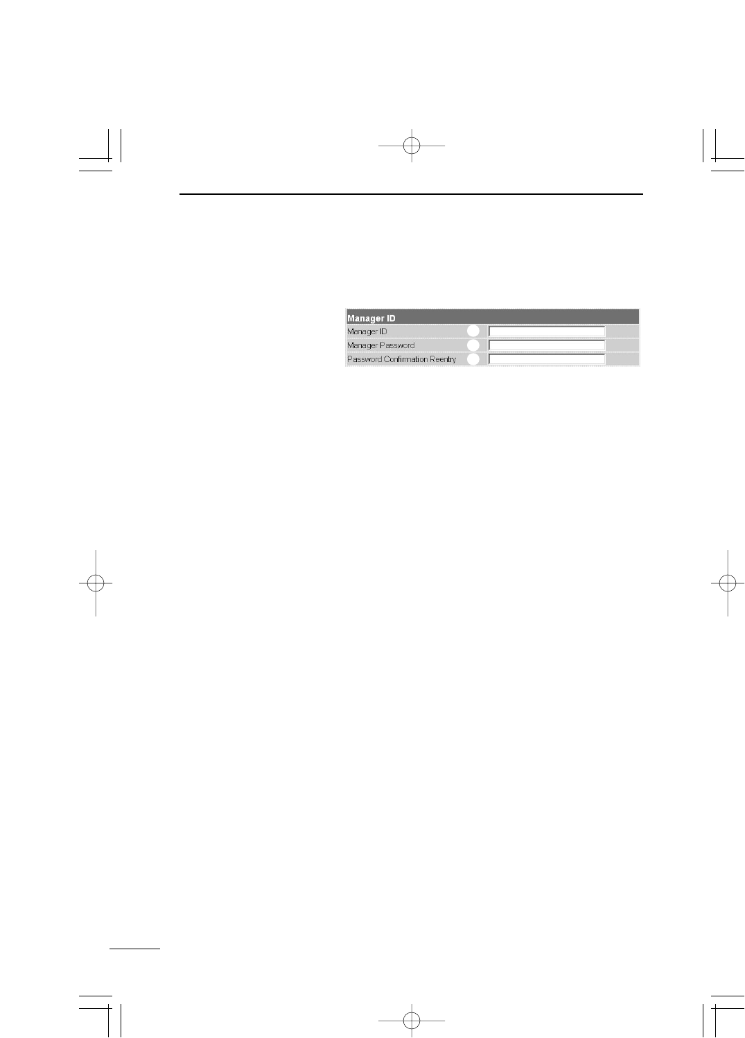
62
SETTING SCREEN
5
5-5 [Administration] Screen
■Manager ID Setting for restriction of access to the setting screen
of SB-110.
If you restrict the access to the setting screen of SB-110,
enter a name of manager within 31 alphanumeric charac-
ters. Please note that the name is case-sensitive.
When the Manager ID has been specified, you are
prompted to enter a user name from the next access.
Then, enter the Manager ID.
If you enter a password for the Manager ID, the password
must be within 31 alphanumeric characters and case-sen-
sitive. The entered characters are all expressed as a as-
terisk (e.g., ****).
When the Manager Password has been specified, you are
prompted to enter such password from the next access.
Then, enter the Manager Password.
To prevent an error in entering the password, enter the
password again. The entered characters are all ex-
pressed as a asterisk (e.g., ****).
qManager ID…………
wManager Password
ePassword Confir-
mation Reentry ……
q
w
e
PDF取説-E_1 02.1.23 10:28 ページ62
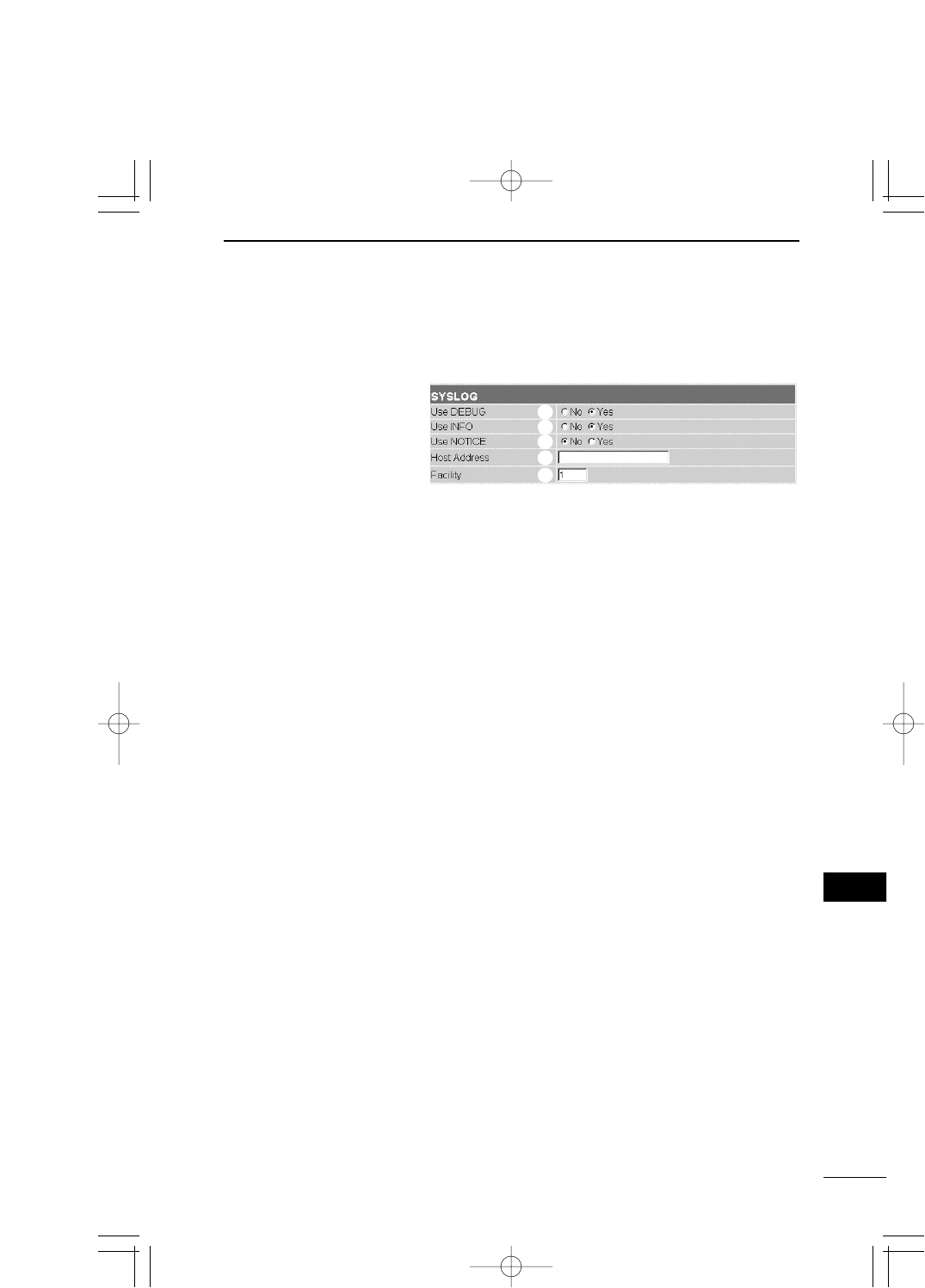
5-5 [Administration] Screen (continued from the previous page)
■SYSLOG
63
SETTING SCREEN 5
5
Specify whether debug information is output to SYSLOG
or not (default setting: Yes).
Specify whether a message of INFO type is output to
SYSLOG or not (default setting: Yes).
Specify whether a message of NOTICE type is output to
SYSLOG or not (default setting: No).
If the SYSLOG function is used, enter an address of a
host which receives SYSLOG.
The host must be able to support the SYSLOG server
function.
Enter a numerical value in a range between 0 and 23 as a
facility of SYSLOG. Usually, enter "1" (default setting: 1).
qUse DEBUG ………
wUse INFO …………
eUse NOTICE ………
rHost Address ……
tFacility………………
q
w
e
r
t
Perform the setting to output log information, etc. to a
specified host address.
PDF取説-E_1 02.1.23 10:28 ページ63
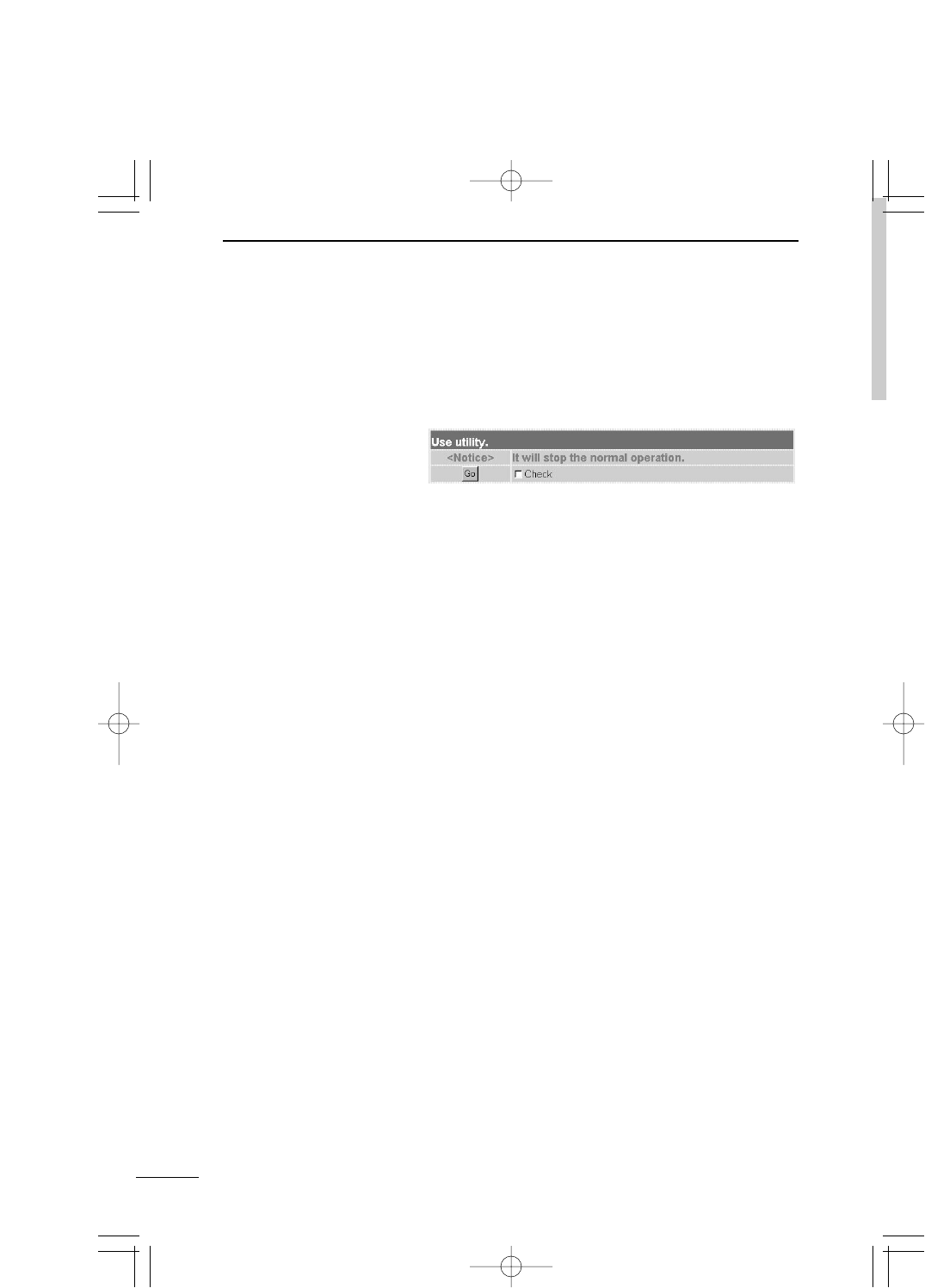
64
SETTING SCREEN
5
5-5 [Administration] Screen (continued from the previous page)
■Use utility (Firmware Update Mode)
Use when you return SB-110 to the default state or up-
date the firmware with the utility which comes with
SB-110.
Check the [Check] check box and click [GO] to enter the
[Use utility] mode and start an operation. This operation
can be executed also by using the [MODE] button of SB-
110. For the detailed operation, refer to "OPERATION"
(Chapter 6).
PDF取説-E_1 02.1.23 10:28 ページ64

CHAPTER 6
MAINTENANCE
6-1 CD-ROM of SB-110 …………………………………………………………………66
■Contents …………………………………………………………………………66
■Auto Run Function ………………………………………………………………66
■Available OS………………………………………………………………………66
■To Start Utility ……………………………………………………………………66
6-2 Restricting Access to Setting Screen ……………………………………………67
6-3 Checking or Saving Settings ………………………………………………………68
6-4 Writing Saved Settings ……………………………………………………………69
6-5 Returning Setting to Default State …………………………………………………70
AUse the [MODE] button. …………………………………………………………70
BUse the setting screen …………………………………………………………72
CUse Utility ………………………………………………………………………73
6-6 Upgrading SB-110 …………………………………………………………………74
■Firmware …………………………………………………………………………74
■How to Update ……………………………………………………………………76
6-7 When the unit fails …………………………………………………………………77
This chapter describes the procedure to restrict the connection to the setting
screen of SB-110, to save or initialize the details and update the firmware.
Read this chapter as necessary.
PDF取説-E_1 02.1.23 10:28 ページ65
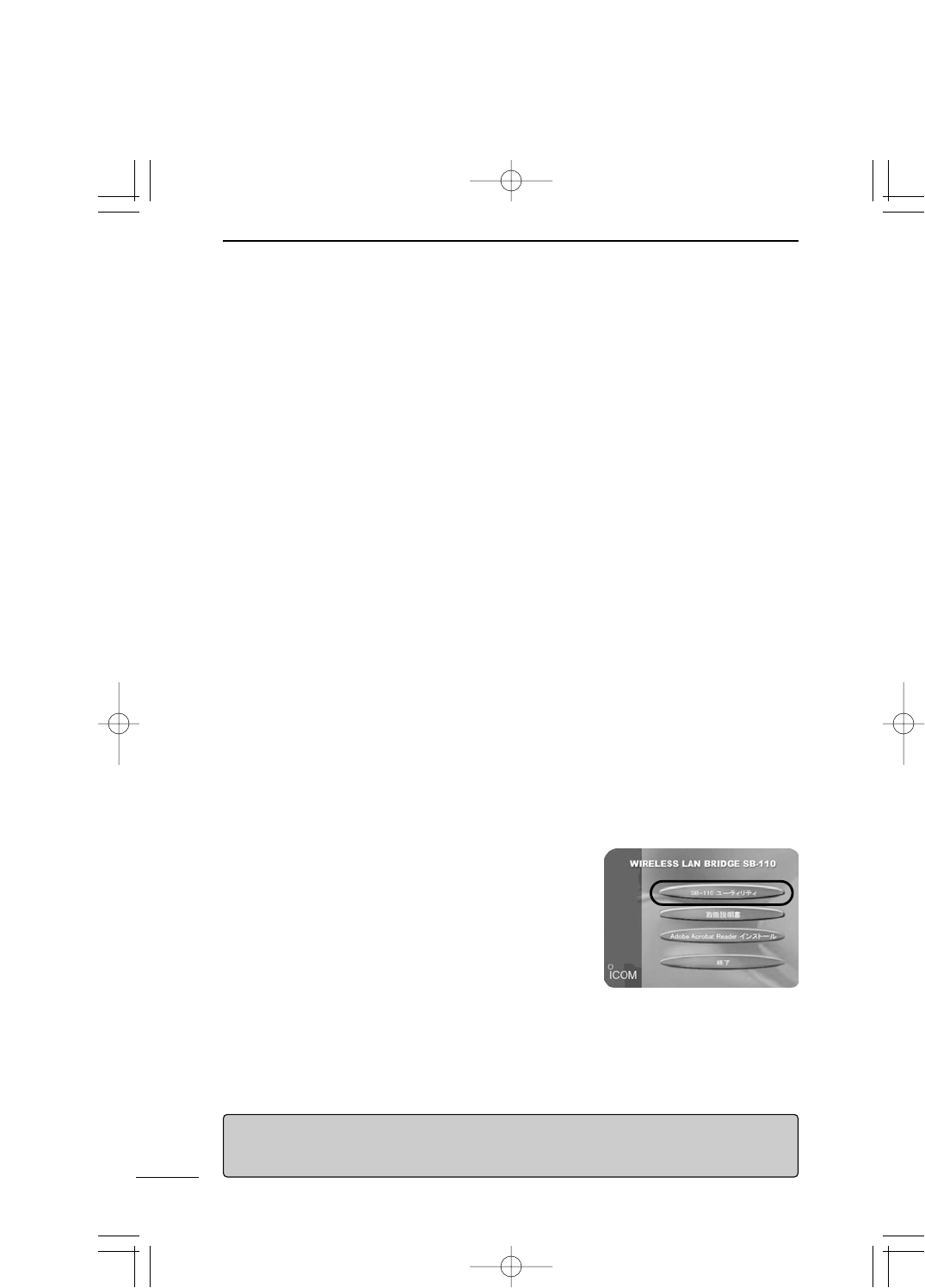
6-1 CD-ROM of SB-110
The CD-ROM which comes with SB-110 can be used in any PC/AT compatible machine.
This CD-ROM contains the instruction manual (of PDF format) and Utility.
■Contents
¡Instruction Manual of PDF Format (this document)
Describes SB-110 in detail.
¡Acrobat Reader 5.0 (for Windows)
Software to view the PDF files contained the CD-ROM. (Install according to the in-
struction screen of the installer.)
¡SB-110 Utility (for Windows)
Use to initialize (☞see 6-6) the entire configuration of SB-110 or update (☞see 6-6) it.
■Auto Run Function
When you insert the CD-ROM into a CD-ROM drive of your PC/AT compatible machine, a
menu screen is shown automatically.
■Available OS
Utility contained in the CD-ROM of SB-110 can be used in the following operating sys-
tems:
Windows 98, Windows 98SE, Windows 2000 and Windows Me.
■To Start Utility
Utility is contained in the CD-ROM which comes with SB-110.
1. Insert the CD-ROM, which comes with SB-110, into a
CD-ROM drive of your PC.
¡The Auto Run function of the CD-ROM of SB-110
starts and a menu screen is displayed automatically.
2. Click [SB-110 Utility].
¡SB-110 Utility starts.
66
MAINTENANCE
6
[When Auto Run function does not start]
Double-click the AutoRun.exe in the [CD-ROM Drive] icon through the Explorer, and the menu
screen above is displayed.
PDF取説-E_1 02.1.23 10:28 ページ66
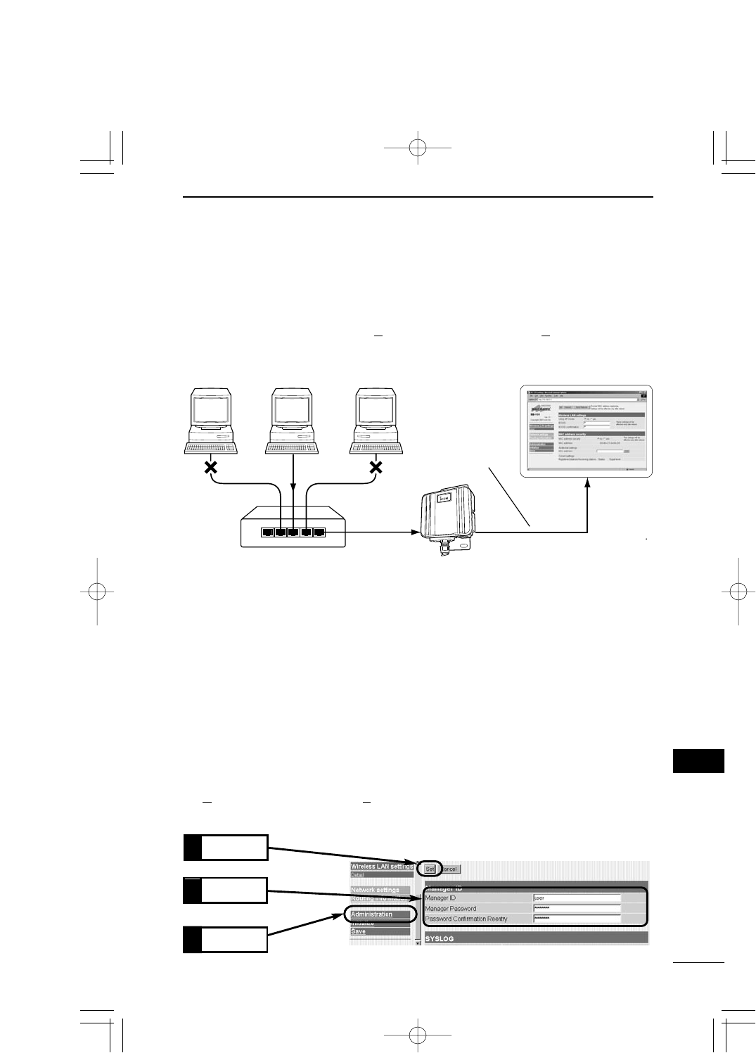
67
MAINTENANCE 6
6
<How to set>
The Manager enters a maximum of 31 half size alphanumeric characters which are case-
sensitive.
1. Start a WWW browser and access the SB-110 setting screen (☞see 4-2).
¡The [Wireless LAN Settings] screen is shown.
2. Click [Administration] in the left frame.
¡The [Administration] screen is shown.
3. Enter the manager ID in the [Manager ID] field (e.g., "user").
4. Enter the manager password in the [Manager Password] and [Password Confirmation
Reentry] fields (e.g., userpass).
The entered characters are all expressed as a asterisk (e.g., ********).
5. Click [Set], and a screen is shown to prompt you to enter the user name [User Name
(U)] and password [Password (P)].
Then, enter the specified manager ID and manager password.
Enter
2.
Click
3.
Manager UserUser
The Manager
accesses with
his/her ID and
password.
Setting Screen
HUB
Click
1.
6-2 Restricting Access to Setting Screen
When you specify the Manager ID and Manager Password, you can prevent any unautho-
rized person from changing the setting screen of SB-110 through a WWW browser.
If the Manager ID and Manager Password are specified, a screen to prompt an operator to
enter the user name [User Name (U)] and password [Password (P)] when he/she ac-
cesses.
PDF取説-E_1 02.1.23 10:28 ページ67
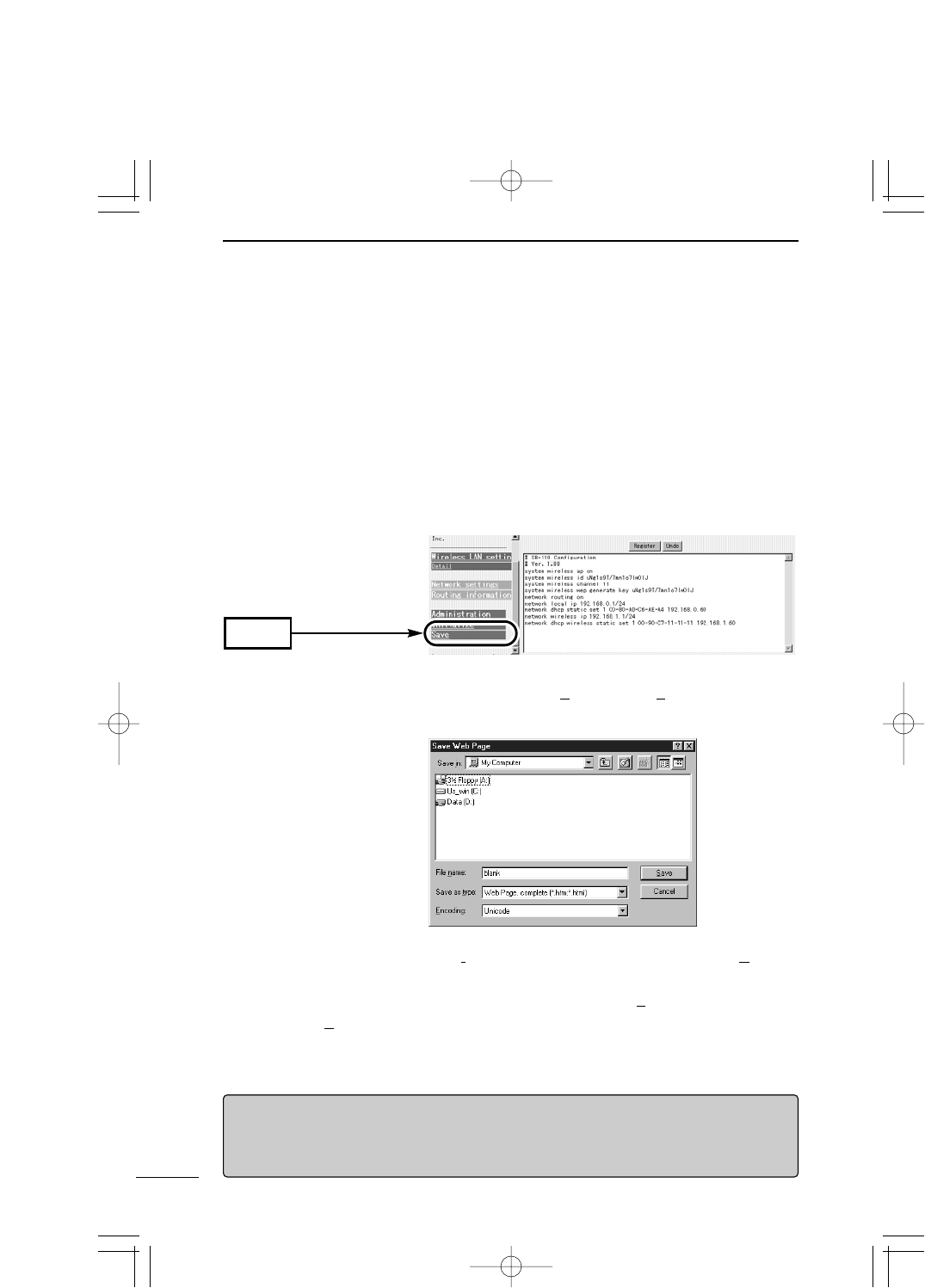
68
MAINTENANCE
6
6-3 Checking or Saving Settings
You can check the details specified in every setting screen of SB-110 and can save them
in a file of hypertext (HTML) format.
You can use the saved settings when the settings have been lost by accident.
<How to check and save>
1. Start a WWW browser and access the SB-110 setting screen (☞see 4-2).
¡The [Wireless LAN Settings] screen is shown.
2. Click [Save] in the left frame.
¡The details of settings are listed in the [Save] screen.
* Do not delete nor rewrite any description in the text box.
3. When the [Save] screen is shown, click [Save As (A)] in the [File (F)] menu of the WWW
browser.
Password displayed in [Save] screen
The details of the manager password and key generator (character strings from which a en-
cryption key is generated) displayed in the [Save] screen are encrypted. So, the password in
the saved configuration file is never revealed.
4. Select the location from [Save in (I)] and enter a file name in the [File Name (N)] box.
* If you use Netscape Navigator, specify ".htm" or ".html" as the file extension.
5. Select "Web Page, complete (*.htm;*.html)" from [File Types(T)]. (Internet Explorer)
6. Click [Save (S)], and the configuration file is saved in the specified location.
Click
PDF取説-E_1 02.1.23 10:28 ページ68
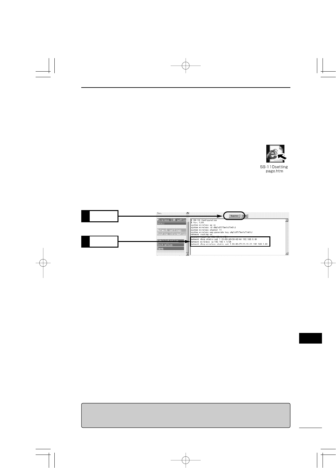
69
MAINTENANCE 6
6
6-4 Writing Saved Settings
This section describes the procedure to write the details of a saved configuration file (☞
see 6-3) into the SB-110 setting screen.
<How to write>
1. Move a cursor from a PC connected to SB-110 to a saved configuration
file with the extension ".htm" and double-click it.
¡The [Save] screen is shown.
2. Check the IP address of SB-110 in the text box.
If the displayed IP address is different from the set SB-110 IP address, change the SB-
110 IP address in the configuration file according to the SB-110 IP address set cur-
rently. Do not change any other items.
3. Click [Register].
Click
2.
4. When you click [Register], the details of the configuration file are written into SB-110.
* If you set anything after you write the details of the configuration file, close the screen
once. Otherwise, an error may occur. Be sure to start the WWW browser again when
you access the setting screen.
[RRemarks]
Do not write any configuration file created by SB-110 into any products of the same type nor
any products other than SB-110.
Check
1.
PDF取説-E_1 02.1.23 10:28 ページ69

70
MAINTENANCE
6
6-5 Returning Setting to Default State
When you want renew the setting to change the network configuration or you want to
delete all the existing setting data, you can return the entire setting to the default state (ini-
tialize) in the three ways below:
AUse the [MODE] button.
BUse the setting screen (☞see page 72).
CUse Utility (☞see page 73).
* To return the setting to the default state with Utility, you need to start Utility in the CD-
ROM which comes with SB-110. For how to start it, refer to "To Start Utility" in the "CD-
ROM of SB-110" (☞see 6-1).
AUse the [MODE] button.
When the initialization is executed in this way, all the setting items are returned to the de-
fault state. If the IP address set in SB-110 is unknown or the SB-110 setting screen can-
not be shown, you can perform the initialization according to the procedure below:
<How to initialize>
1. Remove the power supply from SB-110.
2. Remove all the network devices from SB-110.
3. Connect an AC adapter to SB-110 holding down the [MODE] button and turn on the
power supply.
4. Release the [MODE] button when the [PWR] indicator and [MODE] indicator, which
were blinking (in green) alternately, has started blinking (in green) simultaneously.
¡Enter the [INITIALIZATION] mode and start an operation.
5. Connect a PC to SB-110 through cable (☞see 4-1) and start the operating system.
6. Start a WWW browser and specify the default IP address (192.168.0.1) of SB-110.
[INITIALIZATION] mode
When the [INITIALIZATION] mode is enabled by operating the [MODE] button, the IP address
and ESS ID of SB-110 are replaced with the default state temporarily until the initialization
(the procedure after the step 7 above) has been completed actually. If you turn on the power
supply of SB-110 without performing the procedure after the step 7, the setting is returned to
the default state.
PDF取説-E_1 02.1.23 10:28 ページ70
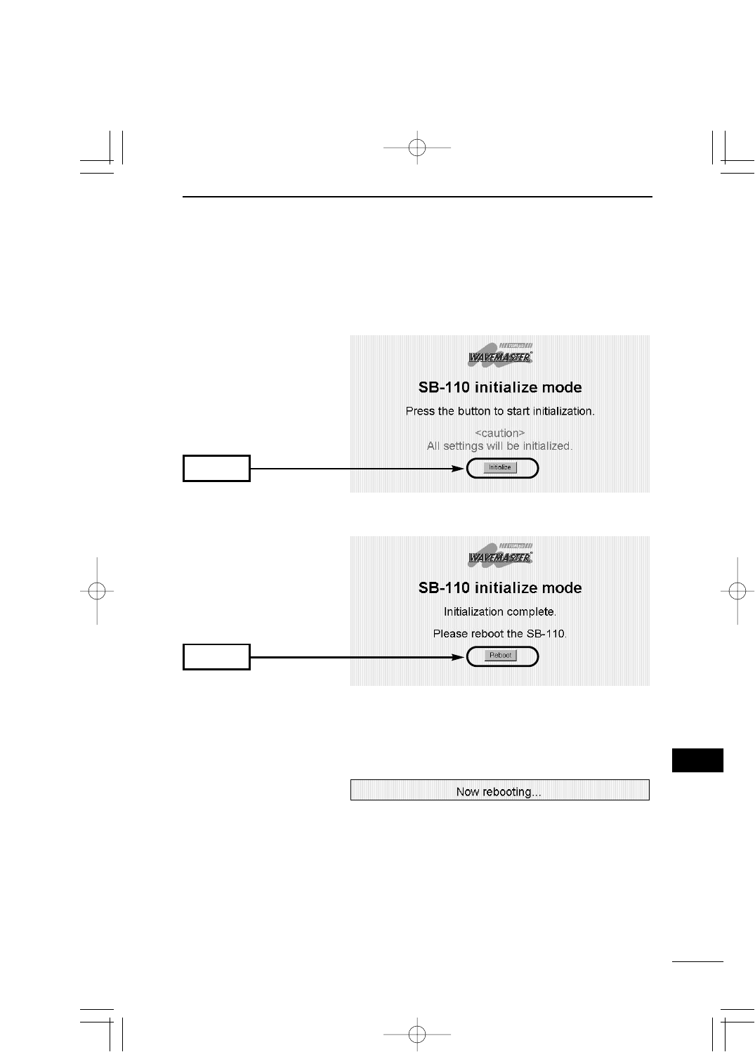
71
MAINTENANCE 6
6
6-5 Returning Setting to Default State
BUse the [MODE] button.
<How to initialize> (continued from the previous page)
7. When the [INITIALIZATION] mode screen is shown, click [Initialize].
Click
8. Click [Reboot].
Click
9. When the indicators of SB-110 have been returned to the state before the [INITIALIZA-
TION] mode is enabled and when the [Wireless LAN Settings] screen has been shown,
the initialization ends.
¡During rebooting, the screen below is shown.
PDF取説-E_1 02.1.23 10:28 ページ71
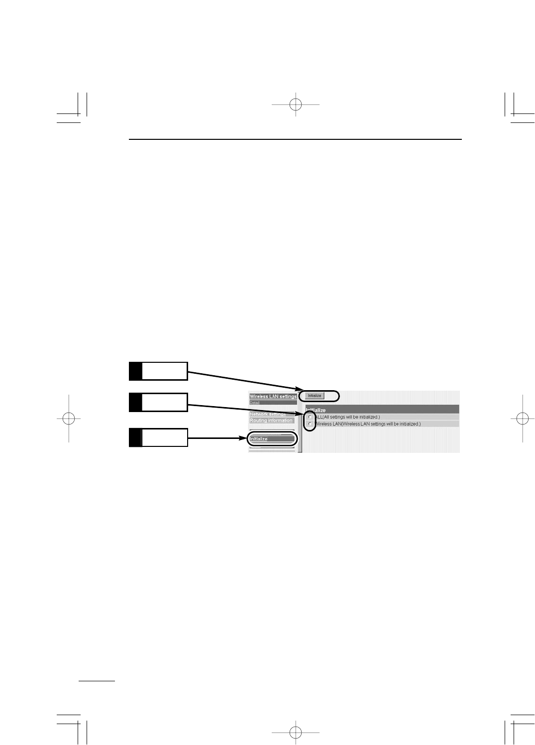
72
MAINTENANCE
6
6-5 Returning Setting to Default State (continued from the previous page)
BUse the setting screen
If you know the IP address set in SB-110 and you can access the setting screen with such
IP address, you can initialize all the settings or a certain part of the settings (e.g., the wire-
less section) through the SB-110 setting screen.
<How to initialize>
1. Start a WWW browser and access the SB-110 setting screen (☞see 4-2).
¡The [Wireless LAN Settings] screen is shown.
2. Click [Initialize] in the left frame.
¡The [Initialize] screen is shown.
3. Click a radio button of desired condition.
4. Click [Initialize].
¡Return the setting equivalent to the selected condition to the default state and enter
the [Wireless LAN Settings] screen.
All the settings specified in SB-110 are returned to the default
state.
The items in the [Wireless LAN Settings] screen and [Detail
Settings] screen are returned to the default state.
ALL ……………………
Wireless LAN …………
■Type of Initialization
Click
1.
Select
2.
Click
3.
PDF取説-E_1 02.1.23 10:28 ページ72

73
MAINTENANCE 6
6
[Use utility] mode
When the [Use utility] mode is enabled by operating the [MODE] button, the wireless LAN se-
curity setting (WEP function) of SB-110 is disabled temporarily until Utility operation has been
completed actually. If Utility is used in a wireless terminal, disable the WEP function of a PC.
6-5 Returning Setting to Default State (continued from the previous page)
CUse Utility
Utility is contained in the CD-ROM of SB-110. This section describes the procedure to
initialize the settings with Utility.
◆Before using Utility ◆
To return the SB-110 settings to the default state with Utility, enter the [Use utility] mode.
Otherwise, you cannot use Utility to initialize the settings. You need to access SB-110
and assign the IP address to your PC in advance.
<How to enter [Use utility] mode>
This section describes the procedure to enter the [Use utility] mode using the [MODE] but-
ton. You may also enter the [Use utility] mode through the [Administration] screen
(☞see 5-5).
1. Remove the power supply from SB-110.
2. Remove all the network devices from SB-110.
3. Connect an AC adapter to SB-110 holding down the [MODE] button and turn on the
power supply.
4. Release the [MODE] button before the [PWR] indicator and [MODE] indicator, which
were blinking (in green) alternately, start blinking (in green) simultaneously.
¡Enter the [Use utility] mode and start an operation.
<How to initialize>
1. Check that SB-110 is operating in the [Use utility] mode. Then, connect a PC to SB-110
through cable or by wireless and start the operating system.
2. Start [SB-110 Utility].
For how to start it, refer to "To Start Utility" in the "CD-ROM of SB-110" (☞see 6-1).
¡The operation screen of Utility is shown. (Refer to the screen at the next page.)
3. Click the [User Data Initialization] radio button.
Enter the IP address of SB-110 in the [SB-110 IP address] text box and click [Start].
4. When the message "User data initialization has been completed." has been displayed
on the [SB-110 Utility] screen, the initialization of SB-110 ends.
PDF取説-E_1 02.1.23 10:28 ページ73
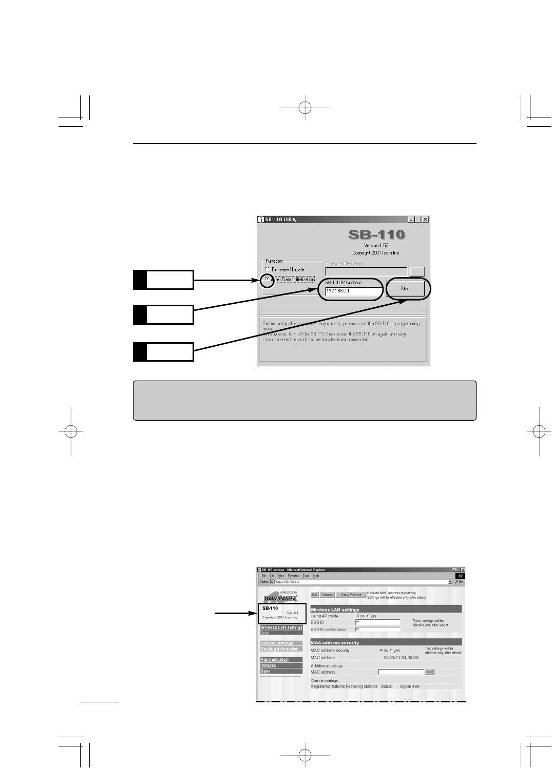
74
MAINTENANCE
6
6-5 Returning Setting to Default State (continued from the previous page)
<How to initialize> (An operation of the step 3)
Click
1.
Enter
2.
Click
3.
[RRemarks]
Do not quit Utility nor turn off SB-110 during the execution of Utility. Otherwise, data may be
lost or an error may occur in an operation. Wait until "... has been completed." is shown.
6-6 Upgrading SB-110
Use Utility contained in the CD-ROM of SB-110. This section describes the procedure to
upgrade SB-110 (firmware) with Utility.
■Firmware
The firmware is a program written into flash memory of SB-110 by default. This program
may be upgraded to extend the function or improve the performance. Before upgrading it,
access the SB-110 setting screen and check the version information displayed in the frame
as shown below. A function can be added and SB-110 can be kept in the best condition.
Version Information
PDF取説-E_1 02.1.23 10:28 ページ74
75
MAINTENANCE 6
6
6-6 Upgrading SB-110
■Firmware (continued from the previous page)
◆Before using Utility ◆
To upgrading the firmware with Utility, enter the [Use utility] mode. Otherwise, you cannot
use Utility to update the firmware. You need to access SB-110 and assign the IP address
to your PC in advance.
<How to enter [Use utility] mode>
This section describes the procedure to enter the [Use utility] mode using the [MODE] but-
ton. You may also enter the [Use utility] mode through the [Administration] screen
(☞see 5-5).
1. Remove the power supply from SB-110.
2. Remove all the network devices from SB-110.
3. Connect an AC adapter to SB-110 holding down the [MODE] button and turn on the
power supply.
4. Release the [MODE] button before the [PWR] indicator and [MODE] indicator, which
were blinking (in green) alternately, start blinking (in green) simultaneously.
¡Enter the [Use utility] mode and start an operation.
◆Notes on Updating ◆
To prevent an error in firmware transfer, connect one PC, in which Utility is installed, to
one SB-110 through cable or by wireless. It is advisable to connect the PC and SB-110
through a hub on Ethernet LAN (☞see 4-1).
¡If you connect the PC and SB-110 by wireless, follow the instructions below.
Enable the Access Point mode (☞see 4-3).
Disable the wireless LAN security (WEP function) of the PC.
Remove the SB-110's Ethernet cable from the PC.
Keep the wireless communication distance to SB-110 1 m or less.
[Use utility] mode
When the [Use utility] mode is enabled by operating the [MODE] button, the wireless LAN se-
curity setting (WEP function) of SB-110 is disabled temporarily until Utility operation has been
completed actually. If Utility is used in a wireless terminal, disable the WEP function of a PC.
You are responsible for the result of operation described herein. So, please follow the
instructions below when you start an operation.
◎The CD-ROM (excluding Acrobat Reader) which comes with SB-110 is for SB-110 only. Do not
use it for any other devices.
◎Icom Inc. is not responsible for any interference arisen by incorporating a configuration file for SB-
110 or a firmware update data file, which is available in our home page, into any device other than
SB-110. Moreover, Icom Inc. is not responsible for any interference arisen by modifying or disas-
sembling SB-110. Furthermore, Icom Inc. is not responsible for any damages, lost profits or third
party's claim resulting from any missed communication or telephone call due to SB-110's fault,
error, malfunction, breakage, data loss or any other external factor such as power failure.
PDF取説-E_1 02.1.23 10:28 ページ75
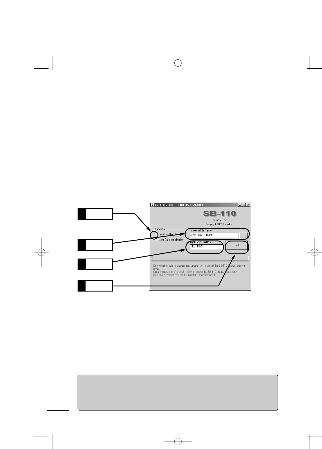
76
MAINTENANCE
6
6-6 Upgrading SB-110 (continued from the previous page)
■How to Update
1. Check that SB-110 is operating in the [Use utility] mode. Then, connect a PC to SB-
110 through cable or by wireless and start the operating system.
2. Start [SB-110 Utility].
For how to start it, refer to "To Start Utility" in the "CD-ROM of SB-110" (☞see 6-1).
¡The operation screen of Utility is shown. (Refer to the screen.)
3. Click the [Firmware Update] radio button.
Enter a link to a downloaded new configuration file (extension: dat) of SB-110 in the
[Firmware File Name] text box directly or click [...] to select the file. Then, enter the IP
address of SB-110 in the [SB-110 IP Address] text box and click [Start]. (Refer to the
screen.)
Enter
2.
Enter
3.
4. When the message "Firmware update has been completed." has been displayed on
the [SB-110 Utility] screen, the initialization of SB-110 ends.
[Time required for update]
Time elapsed to reboot the system since the firmware data file was transferred to SB-110
from a wired or wireless terminal is as follows:
¡Transfer: 30 to 60 seconds
¡Reboot: 30 seconds
Click
1.
Click
4.
PDF取説-E_1 02.1.23 10:28 ページ76

77
MAINTENANCE 6
6
6-7 When the unit fails
Warranty conditions may differ depending on your dealer.
Please ask your dealer when you purchase the SB-110 about the Warranty and
its conditions.
Basic conditions are as follows:
Warranty
At the time of purchase, the retailer will provide a warranty sheet complete with
the details of the purchase (date of purchase, name of local dealer, etc.). Make
sure the information is correct and keep the warranty in a safe place for future
use.
Requesting servicing
Refer to the instruction manual and check the settings of both the computer and
the SB-110 unit. If you cannot solve the problem yourself, request servicing
according to the following terms:
Contact the local dealer where you purchased the product.
The retailer will service the product in accordance with the warranty. Have your
warranty ready at the time of request.
Contact the local dealer where you purchased the product.
If the product is serviceable, the retailer will repair the product for a fee.
Questions Regarding Service
If you have any questions regarding service, contact the local dealer where you
purchased the product, or contact the service staff at one of our sales offices.
After the Warranty period has expired.
While the Warranty is valid.
PDF取説-E_1 02.1.23 10:28 ページ77

PDF取説-E_1 02.1.23 10:28 ページ78
CHAPTER 7
FOR YOUR REFERENCE
7-1 Examples of Routing Setting ………………………………………………………80
■Setting RIP Function ……………………………………………………………80
■Setting Routing Table ……………………………………………………………80
7-2 Setting Screen Overview……………………………………………………………83
7-3 List of Initial Values of Setting Items ………………………………………………84
7-4 List of Functions ……………………………………………………………………84
7-5 Rating …………………………………………………………………………………85
7-6 Specifications for Ethernet Plug……………………………………………………86
7-7 Glossary………………………………………………………………………………87
This chapter describes the examples of routing setting, setting screen
overview, initial value of setting item and rating.
PDF取説-E_1 02.1.23 10:28 ページ79
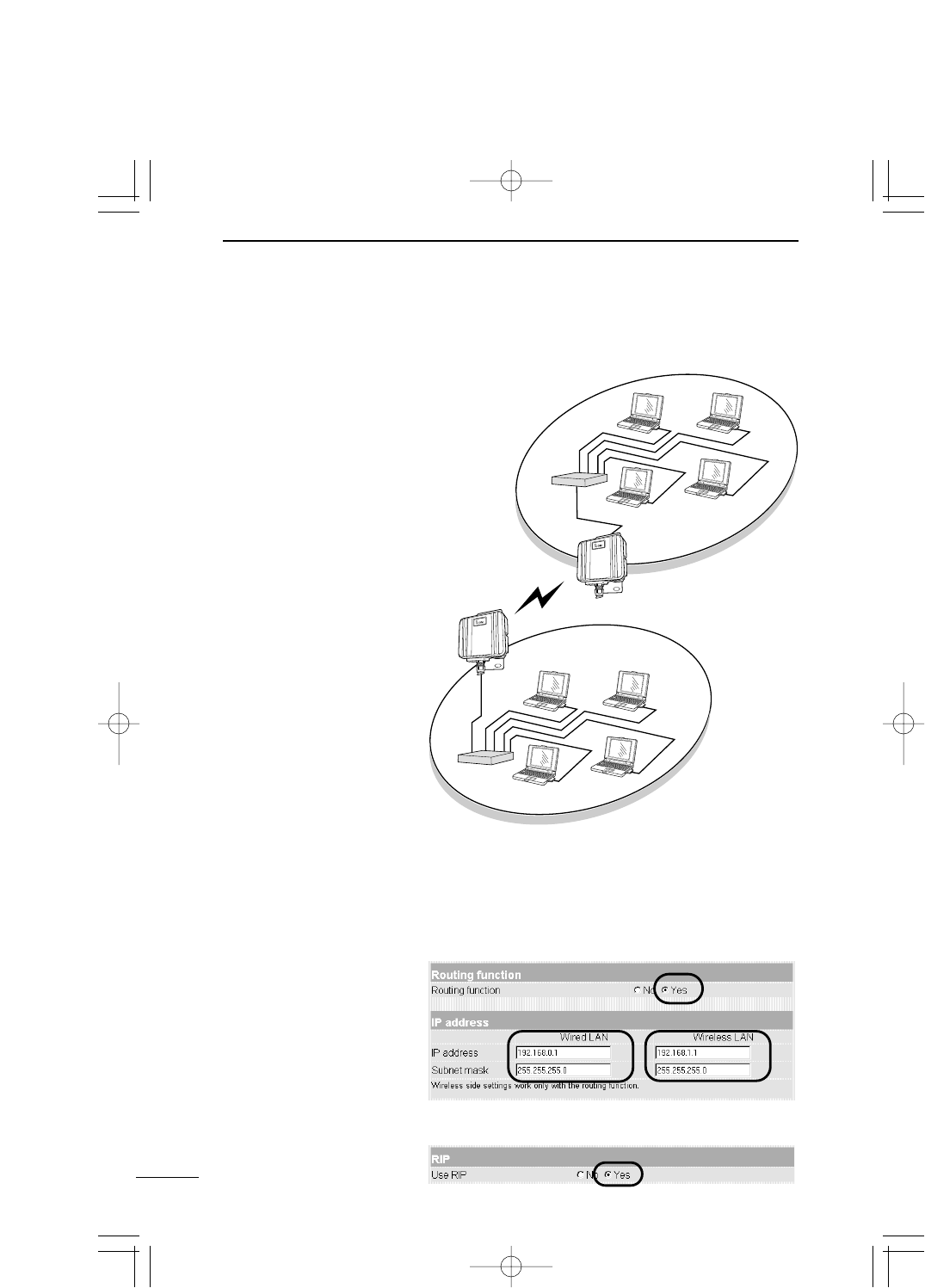
[Setting conditions of
floor A]
¡IP address of SB-110
[Wired side]
192.168.0.1.
[Wireless side]
192.168.1.1.
¡IP address of wired
terminal
192.168.0.10 to
192.168.0.13
(4 addresses)
[Setting conditions of
floor B]
¡IP address of SB-110
[Wired side]
192.168.2.1.
[Wireless side]
192.168.1.2.
¡IP address of wired
terminal
192.168.2.10 to
192.168.2.13
(4 addresses)
80
FOR YOUR REFERENCE
7
7-1 Examples of Routing Setting
This section describes two examples of settings in a network. One is for the RIP function
and another one is for the routing table.
Floor A
HUB
HUB
SB-110
Floor B
SB-110
Wired side
Wireless side
Wired side
■Setting RIP Function
[IP address] Screen (☞see 5-3)
[Routing Function] Screen (☞see 5-4)
[SB-110: Floor A side]
* Specify the IP address at
the wired side of SB-110
as a default gateway in a
wired terminal.
PDF取説-E_1 02.1.23 10:28 ページ80
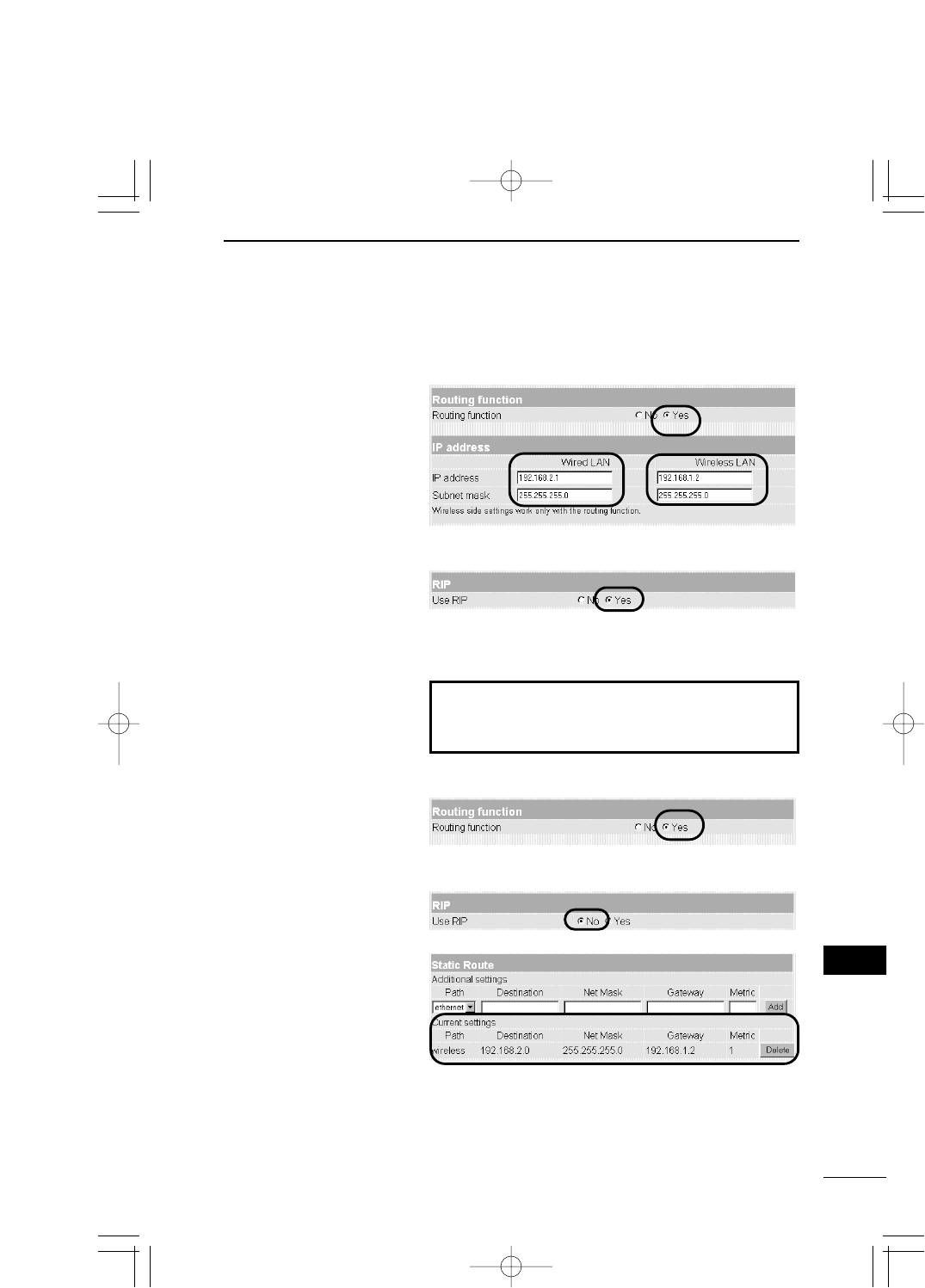
Communication can be made similarly also by checking
the [NO] radio button of [Routing function] when you
create the routing table.
81
FOR YOUR REFERENCE 7
7
[IP address] Screen (☞see 5-3)
[Routing Function] Screen (☞see 5-4)
[SB-110: Floor B side]
* Specify the IP address at
the wired side of SB-110
as a default gateway in a
wired terminal.
7-1 Examples of Routing Setting
■Setting RIP Function (continued from the previous page)
■Setting Routing Table
[SB-110: Floor A side]
[IP address] Screen (☞see 5-3)
[Routing Function] Screen (☞see 5-4)
[SB-110: Floor B side]
Refer to the next page.
PDF取説-E_1 02.1.23 10:28 ページ81
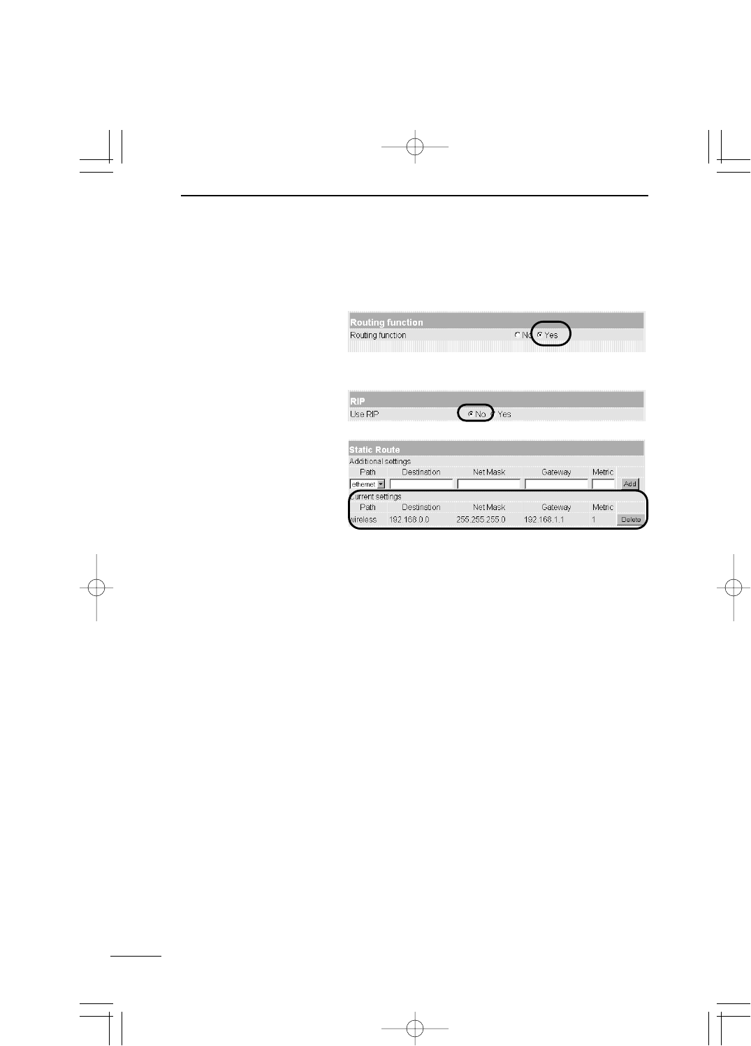
82
FOR YOUR REFERENCE
7
[SB-110: Floor B side]
7-1 Examples of Routing Setting
■Setting Routing Table (continued from the previous page)
[IP address] Screen (☞see 5-3)
[Routing Function] Screen (☞see 5-4)
PDF取説-E_1 02.1.23 10:28 ページ82
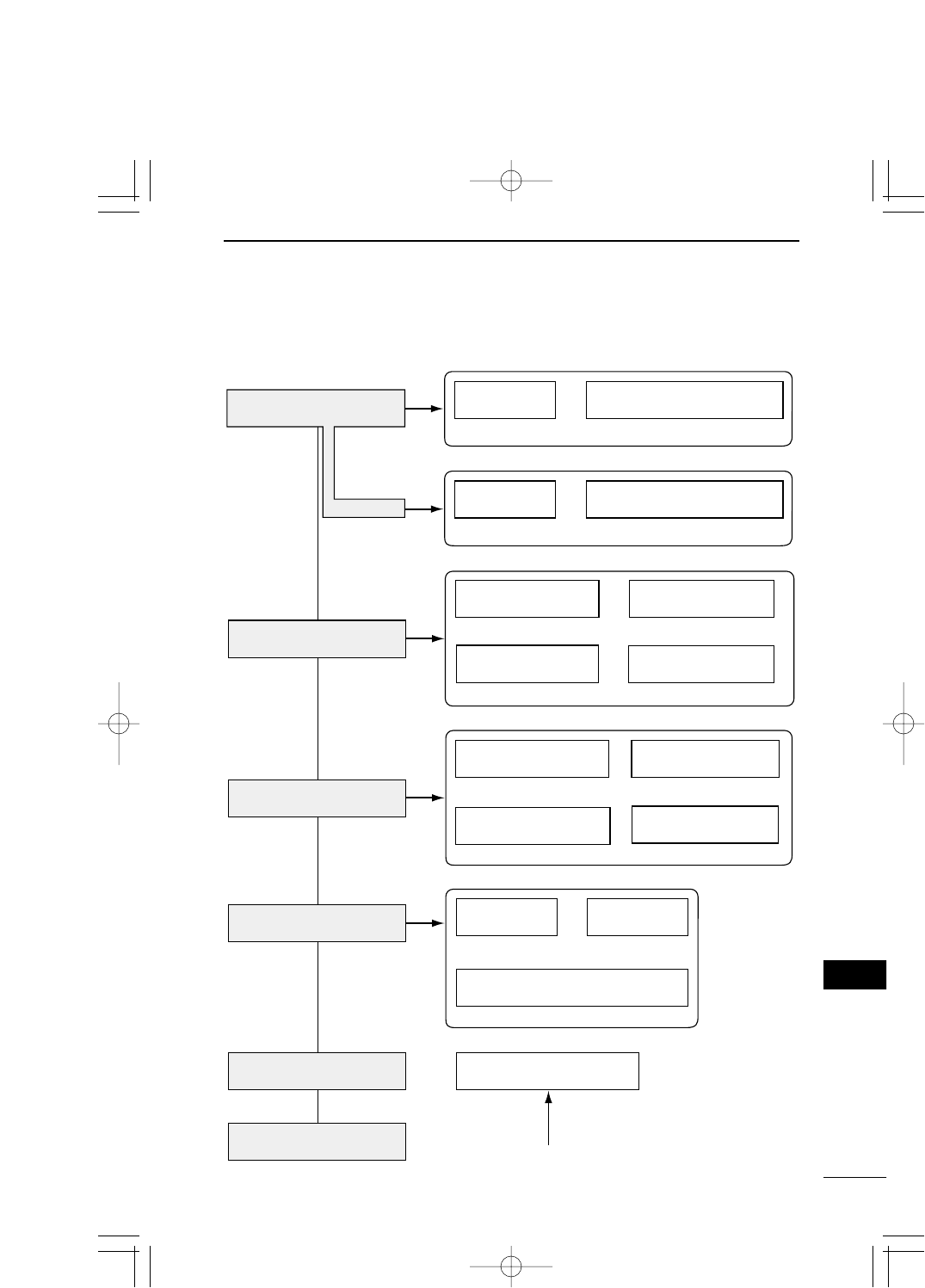
83
FOR YOUR REFERENCE 7
7
7-2 Setting Screen Overview
The overview of SB-110 setting screen displayed on a WWW browser is shown below.
Static Route
Network Interface List
Routing function
Static DHCP Server
DHCP Server
Manager ID SYSLOG
IP address
RIP
IP Routing Information
[Save] Screen
[Initialization Mode] Screen
[Wireless LAN Settings]
Screen
Detail Settings
MAC Address Security Setting
Detail Settings
Wireless LAN
Settings
Custom Security
Use utility (Firmware Update Mode)
[Routing Function] Screen
[Administration] Screen
[Initialize] Screen
[IP address] Screen
(☞ see page 53)
(☞ see page 59)
(☞ see page 62)
(☞ see page 72)
(☞ see page 68)
(☞ see page 53)
(☞ see page 59)
(☞ see page 60)
(☞ see page 62) (☞ see page 63)
(☞ see page 64)
(☞ see page 61)
(☞ see page 59)
(☞ see page 54)
(☞ see page 55) (☞ see page 58)
At startup in the [Initialization Mode].
(☞ see page 71)
(☞ see page 42)
(+ see page 45)
(☞ see page 42) (☞ see page 43)
(☞ see page 45) (☞ see page 47)
PDF取説-E_1 02.1.23 10:28 ページ83

84
FOR YOUR REFERENCE
7
7-3 List of Initial Values of Setting Items
The section lists the initial values in the WWW browser setting screen of SB-110.
[Wireless LAN Settings] Screen
Wireless LAN Settings
¡ESS ID: ** LG
¡Confirmation reentry of ESS ID: ** LG
MAC Address Security Setting
¡MAC address security: no
[Detail Settings] Screen
Detail Settings
¡Channel: 11
¡Transmit Rate: Automatic
¡Rts/Cts Threshold: None
¡Security Level: None
Custom Security
¡WEP Key - Selection: 1
¡WEP Key - Character string: 00-00-00-
00-00
[IP address] Screen
Routing function
¡Routing function: No
IP address
Wired LAN
¡IP address: 192.168.0.1
¡Subnet mask: 255.255.255.0
Wireless LAN
¡IP address: 192.168.1.1.
¡Subnet mask: 255.255.255.0
DHPC Server
¡Use DHPC Server: Yes
¡Lease Period: 3
Wired LAN
¡Initial Allocation IP Address:
192.168.0.10
¡Subnet mask: 255.255.255.0
¡Number of Allocations: 30
Wireless LAN
¡Initial Allocation IP Address:
192.168.1.10
¡Subnet mask: 255.255.255.0
¡Number of Allocations: 30
[Routing Function] Screen
RIP
¡Use RIP: Yes
[Administration] Screen
SYSLOG
¡Use DEBUG: Yes
¡Use INFO: Yes
¡Use NOTICE: No
¡Facility: 1
■Router Functions
¡Routing protocol
TCP/IP (RIP static)
¡Static routing
¡RIP function
¡DHCP server function
¡DHCP static function
¡SYSLOG
7-4 List of Functions
■Wireless LAN Functions
¡Building Communication (Bridge) mode
¡Access Point mode
¡Roaming function
¡MAC address security
¡WEP (Wired Equivalent Privacy)
¡ESS ID (Extended Service Set IDentifier)
■Others
¡WWW maintenance
¡Firmware update
PDF取説-E_1 02.1.23 10:28 ページ84

85
FOR YOUR REFERENCE 7
7
7-5 Rating
■General Specifications
¡Input voltage: DC 12 V (DC 12 V ±5%)
The input voltage of the AC adapter
(which comes with SB-110) is AC 120 V ±5%.
¡Consumption current: 400 mA (typically)
¡Grounding method: Minus earth
¡Installation environment: Temperature 0 to +45゚C
¡Outside dimension: 140.0 (W) x 120.0 (H) x 50.0 (D) mm
(excluding any protrusion)
¡Weight: Approximately 960 g (including cables)
■Wireless Section
¡International standard: IEEE802.11/IEEE802.11b
¡Approval standard: FCC Part 15, Sub Part B, Class A, Part 15.247
¡Communication method: Simplex system
¡Radio wave method: Direct spread-spectrum communication system
¡Modulation method: DPSK, DQPSK, (Burger/CCK code)
¡Usable frequency range: 2400 to 2472 MHz
¡Number of channels: 1 to 11
¡Communication distance: Approximately 800 m
(not to be blocked by any obstruction)
<Building Communication mode>
Approximately 70 m
(not to be blocked by any obstruction)
<Access Point mode>
¡Security: WEP (Wired Equivalent Privacy),
ESS ID (Extended Service Set IDentifier) and
MAC (Media Access Control Address)
¡Transmission output: 1W or less
¡Receiver sensitivity: -76 dBm or less (Frame error rate = 8%)
¡Demodulation method: Digital demodulation (Matched filter system)
PDF取説-E_1 02.1.23 10:28 ページ85
86
FOR YOUR REFERENCE
7
7-5 Rating (continued from the previous page)
■Wired Section
¡LAN interface: Ethernet plug (Type RJ-45)
* Based on IEEE802.3/10BASE-T
* Based on IEEE802.3u/100BASE-TX
¡Transmission rate: 10/100 Mbps (switched automatically/half-duplex)
¡Routing method: Static/Dynamic (RIP)
¡User interface: Status indicator (PWR <Green>, MODE <Green>,
LAN <Red>, <Red>), [MODE] button.
■Antenna Section (for built-in type)
¡Antenna type: Pattern antenna
¡Antenna gain: 5.5 dpi
¡Directional Characteristics of Antenna:
Horizontal: ±30°(attenuation 3 dB)
Vertical: ±30°(attenuation 3 dB)
¡Impedance: 50Ω
¡Standing wave ratio: 1.6 or less
* The rating, specifications, appearance, etc are all subject to change without
notice.
* The transmission distance varies depending on the communication speed and
environment.
7-6 Specifications for Ethernet Plug
Modular plug type RJ-45
1. Sending (+) 2. Sending (-)
3. Receiving (+) 4. Not used
5. Not used 6. Receiving (-)
7. Not used 8. Not used
12345678
PDF取説-E_1 02.1.23 10:28 ページ86

87
FOR YOUR REFERENCE 7
7
Access Point
A generic name of devices or points to connect
a wired LAN and wireless LAN.
Authentication
To check whether a user who is accessing a
network through an internet has the right to ac-
cess and verify whether his/her password and
ID are valid.
Bridge
A generic name of network devices which relay
packets at a MAC address level.
Broadcast
To send several packets to all the devices in
the same network at a time.
Browser
An application to obtain an HTML document
from a WWW server and to view it. This in-
struction manual assume that Internet Explorer,
a typical browser, is used.
Client
A generic name of terminals or applications
which request a server to send information and
receive the reply in a network.
DHCP server
DHCP (Dynamic Host Configuration Protocol)
is a protocol for a client to obtain necessary in-
formation automatically from a server on the
TCP/IP network. The DHCP server controls IP
address, default gateway, domain name, etc.
as network information. SB-110, which has the
DHCP server function, assigned the IP ad-
dress, default gateway, DNS address, etc.
when the DHCP client (PC) has started.
DNS (Domain Name System)
A name resolution service in the TCP/IP net-
work. According to DNS, computer names and
domain names are registered in the domain
name server and the domain name service is
offered. By using the domain name service, a
user can specify a target site with an easy-to-
understand domain name or host name instead
of an IP address which consists of numerical
character string only.
Domain Name
The IP address is not easy to understand be-
cause it consists of numerical character string
only. So, a domain name is used. The domain
name shows a group to which the IP address
belongs. For example, the domain name of an
e-mail address "icom@bbb.co.jp" is "bbb.co.jp".
ESS-ID (Extended Service Set-IDentifier)
A name for identification to create several net-
work groups in a communication area in a wire-
less LAN. In the wireless network group which
communicates to SB-110, the identifier of wire-
less terminal must be the same as that of SB-
110.
ETHERNET
A LAN communication system developed by
Xerox, DEC and Intel. 10BASE-T, 100BASE-
TX, 10BASE-5, 10BASE-2, etc. are available
depending on the cable type.
Flash Memory
Writable memory of SB-110. Information stored
in the flash memory is not erased even when
the power supply turns off.
Global IP Address
A unique address assigned to a device. One
global IP address is assigned to only one de-
vice in the world.
7-7 Glossary
PDF取説-E_1 02.1.23 10:28 ページ87

88
FOR YOUR REFERENCE
7
HTML (Hyper Text Markup Language)
A language to describe a document in a WWW
server. Tags are embedded in the HTML doc-
ument. HTML is used to describe WWW
pages.
HTTP (Hyper Text Transfer Protocol)
A protocol used to transfer HTML file. When
URL is entered in a WWW browser, the HTML
document is transferred from a WWW server to
the WWW browser of a PC with HTTP. The
transferred document is interpreted by the
WWW browser and displayed on the screen.
Hub
A devices required when a network is config-
ured using SB-110. Connect SB-110 to the hub
through 10BASE-T or 100BASE-TX cable. For
the communication in 100 Mbps, the twisted
pair cable of Category 5 must be used and,
moreover, the hub also must support
100BASE-TX.
Internet Explorer
A browsing software which comes with Win-
dows or Mac OS.
IP
A protocol used in the internet. The IP is posi-
tioned at the center of the structure of internet,
some protocols aiming at application are lo-
cated above the IP and some protocols for
communication line are laminated under the IP.
IP (Internet Protocol) Address
32-Bit address to identify all the devices con-
nected to a network in which the TCP/IP proto-
col is used. Usually, the IP address consists of
four 8-bit numerical character strings of decimal
notation (e.g., 192.168.0.1). A private IP ad-
dress is specified by a network administrator.
In this case, the network administrator does not
need to apply to an address administration
agency nor internet service provider. However,
the network administrator must assign the pri-
vate address according to the rules below. The
private address must be converted into a global
IP address when connecting to an external net-
work. The IP addresses below can be used as
the private IP address.
Class A: 10.0.0.0 to 10.255.255.255
Class B: 172.160.0.0 to 172.31.255.255
Class C: 192.168.0.0 to 192.168.255.255
LAN (Local Area Network)
A relatively small-sized network in the same
floor or the same site.
MAC Address (Media Access Control Ad-
dress)
A physical address specified in individual wired
or wireless product. The network device manu-
facturers control this address so that a unique
number can be assigned to only one product in
the world. Ethernet equipment and wireless
LAN product send and receive a frame accord-
ing to this MAC address.
Network
The state that some devices such as server,
workstation, PC, etc. are connected to a com-
munication system through cable or ADSL line
to transmit data.
7-7 Glossary (continued from the previous page)
PDF取説-E_1 02.1.23 10:28 ページ88

89
FOR YOUR REFERENCE 7
7
Packet
A unit to send/receive data. The packet con-
sists of a header, which contains information
necessary for sending/receiving, and data sec-
tion which is data itself.
Password
Character string which must be entered by a
user who is accessing a network because of
network security. If any password is set, the
user cannot access unless the user enter the
valid password correctly.
Protocol
Definition of procedure to executed to send/re-
ceive data in the communication.
RIP (Routing Information Protocol)
A protocol used in a TCP/IP network that rout-
ing information is exchanged between routers.
The router sends a packet to a correct party ac-
cording to this routing information.
Subnet Mask
Subnet mask is used to one IP address as a
network address and host address. Assuming
that the IP address of a host is "192.168.0.1"
and the subnet mask is "255.255.255.0", multi-
ply the IP address of binary notation and sub-
net mask of binary notation together, and the
network address "192.168.0.0" is obtained.
Then, the remainder "1" is the host address.
SYSLOG
A function to output a system message to a net-
work. If this function is supported, log informa-
tion can be controlled by the SYSLOG server of
UNIX etc.
TCP/IP
The most popular basic internet protocol sup-
ported by Windows 98, Windows 2000 and any
other major operating systems. SMTP, FTP,
etc uses this protocol. TCP/IP Control Panel is
installed in Macintosh equipped with Open
Transport.
Traffic
Flow of packets on the network or load applied
to the network line (e.g., data transmitted
through the network line). As the traffic in-
creases, the data transmission rate may de-
crease or data may be lost.
URL (Uniform Resource Locator)
Specify when you access a home page on the
network. Our URL is http://www.icom.co.jp/.
WEP (Wired Equivalent Privacy)
A function to encrypt, send and receive a wire-
less LAN signal. This function can prevent the
wireless LAN communication intercept. SB-110
supports 64/128-bit encryption.
WWW Browser
An application to view a WWW page or to use a
WWW server for search. Typical browser is
"Internet Explorer" and "Netscape Navigator".
10BASE-T
One of the Ethernet standards. 10BASE-T
achieves the transmission rate of 10 Mbit/s with
twisted pair cable. SB-110's Ethernet port sup-
ports this standard.
100BASE-TX
One of the Ethernet standards. 100BASE-TX
achieves the transmission rate of 100 Mbit/s
with twisted pair cable of Category 5. SB-110's
Ethernet port for LAN supports this standard.v
7-7 Glossary (continued from the previous page)
PDF取説-E_1 02.1.23 10:28 ページ89
1-1-32, Kamiminami, hirano-ku, Osaka 547-0003, Japan
A-5681H-1EX ©2001 Icom Inc.
Count on us!
PDF取説-E_1 02.1.23 10:28 ページ90