ICP C8DNL050B12B1 User Manual 80+ SINGLE STAGE GAS FURNACE Manuals And Guides L0601261
ICP Furnace/Heater, Gas Manual L0601261 ICP Furnace/Heater, Gas Owner's Manual, ICP Furnace/Heater, Gas installation guides
User Manual: ICP C8DNL050B12B1 C8DNL050B12B1 ICP 80+ SINGLE STAGE GAS FURNACE - Manuals and Guides View the owners manual for your ICP 80+ SINGLE STAGE GAS FURNACE #C8DNL050B12B1. Home:Heating & Cooling Parts:Icp Parts:Icp 80+ SINGLE STAGE GAS FURNACE Manual
Open the PDF directly: View PDF ![]() .
.
Page Count: 38
80+SingleStage
CategoryI Furnace
DedicatedDownflow
*8DNL
* Denotes Brands (C, H, T)
See section 4 for Category I definition.
SAFETY REQUIREMENTS
Recognize safety information. This is the safety-alert symbolZl._. When you see this symbol on the furnace and in instruction manuals be alert
to the potential for personal injury.
Understand the signal words DANGER, WARNING, or CAUTION. These words are used with the safety-alert symbol. DANGER identifies the
most serious hazards, those that will result in severe personal injury or death. WARNINGsignifiesahazardthatcouldresultinpersonalinjuryor
death. CAUTIONis used to identify unsafe practices that may result in minor personal injury or product and property damage. NOTE is used to
highlight suggestions that will result in enhanced installation, reliability, or operation.
Installing and servicing heating equipment can be hazardous due to gas and electrical components. Only trained and qualified personnel should
install, repair, or service heating equipment.
Untrained service personnel can perform basic maintenance functions such as cleaning and replacing air filters. All other operations must be
performed by trained service personnel. When working on heating equipment, observe precautions in the literature, on tags, and on labels at-
tached to or shipped with the furnace and other safety precautions that may apply.
Follow all safety codes. In the United States, follow all safety codes including the National Fuel Gas Code (NFGC) ANSI Z223.1-2002/NFPA
54-2002. In Canada, refer to the National Standard of Canada Natural Gas and Propane Installation Code (NSCNGPIC) CSA B149.1-05. Wear
safety glasses and work gloves. Have fire extinguisher available during start-up and adjustment procedures and service calls.
These instructions cover minimum requirements and conform to existing national standards and safety codes. In some instances, these instruc-
tions exceed certain local codes and ordinances, especially those that may not have kept up with changing residential construction practices. We
require these instructions as a minimum for a safe installation.
INSTALLER: Affix these instructions on
or adjacent to the furnace.
International Comfort Products, LLC
Lewisburg, TN 37097
Table of Contents
CONSUMER: Retain these instructions
for future reference.
1. Safe Installation Requirements ................ 3
2. Installation ............................... 4
3. Combustion & Ventilation Air ................. 6
4. Gas Vent Installation ........................ 9
5. Horizontal Venting ......................... 11
6. Masonry Chimney Venting ................... 13
7. Gas Supply andPiping ....................... 16
8. Electrical Wiring ........................... 18
9. Ductwork and Filter ......................... 19
10.Checks and Adjustments..................... 23
11.FurnaceMaintenance........................ 27
12.Sequence of Operation & Diagnostics ........... 28
TechSupport and Parts ......................... 31
CARBON MONOXIDE POISONING AND FIRE
HAZARD.
Failure to follow safety warnings exactly could
result in serious injury, death, and/or property
damage.
This furnace is not designed for use in mobile
homes, trailers or recreational vehicles.
Portions of the textand tablesare reprinted from NFPA 54 /ANSI Z223,1-2002©, with permission of National Fire Protection Association, Quincy, MA 02269 and American Gas Association,
Washington, DC 20001. This reprinted material is not the complete and official position of the NFPA or ANSI, on the referenced subject, which is represented only by the standard in its
entirety.
PrintedinU.S.A. 11/10/2005 441 01 2314 (02)
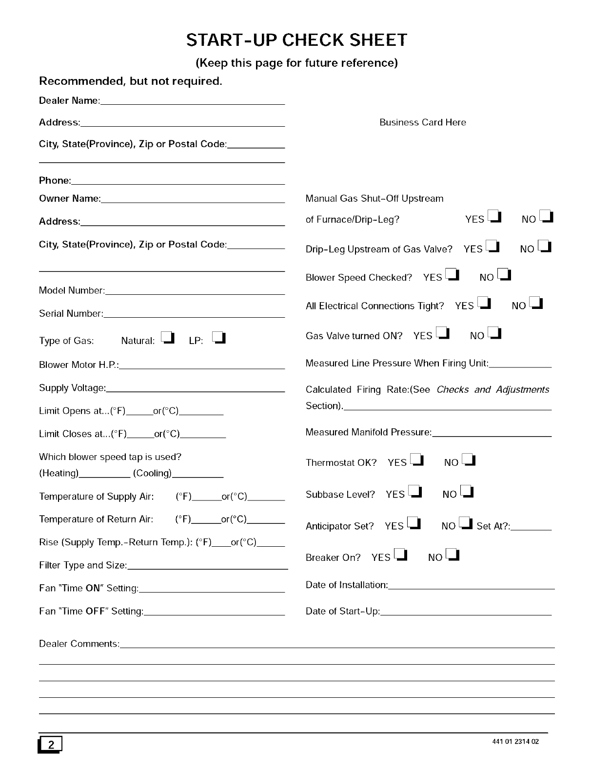
START-UP CHECK SHEET
(Keep this page for future reference)
Recommended, but not required,
Dealer Name:
Address:
City, State(Province), Zip or Postal Code:
Business Card Here
Phone:
Owner Name:
Address:
City, State(Province), Zip or Postal Code:
Model Number:
Serial Number:
Natural: _1 LP: _1
Type of Gas:
Blower Motor H. P,:
Supply Voltage:
Limit Opens at...(°F) or(°C).
Limit Closes at,,,(°F)___or(°C)
Which blower speed tap is used?
(Heating) (Cooling).
Temperature of Supply Air: (°F)___or(°C)
Temperature of Return Air: (°F) or(°C)__
Rise (Supply Temp.-Return Temp.): (°F) or(°C)__
Filter Type and Size:
Fan "Time ON" Setting:.
Fan "Time OFF" Setting:
Manual Gas Shut-Off Upstream
of Furnace/Drip- Leg?
Drip-Leg Upstream of Gas Valve?
Blower Speed Checked? YES _1
All Electrical Connections Tight?
Gas Valve turned ON? YES _1
YES_I NO_I
YES_I NO_I
NO [_I
YEs_I NO[31
NO[_I
Measured Line Pressure When Firing Unit:
Calculated Firing Rate:(See Checks and Adjustments
Section).
Measured Manifold Pressure:
Thermostat OK? YES _1
Subbase Level? YES _1
Anticipator Set? YES _1
Breaker On? YES _1
Date of Installation:
Date of Start-Up:
NOE_
NOE_I
NO E_ Set At?:
NoE_I
Dealer Comments:
441 01 2314 02
1. Safe Installation Requirements
FIRE, EXPLOSION, AND ASPHIXIATION HAZARD
Improper adjustment, alteration, service,
maintanence or installation could cause death,
personal injury, and/or property damage.
Installation or repairs made by unqualified
persons could result in hazards to you and others.
Installation MUST conform with local codes or, in
the absence of local codes, with codes of all
governmental authorities havingjurisdiction.
The information contained in this manual is
intended for use by a qualified service agency that
is experienced in such work, is familiar with all
precautions and safety procedures required in
such work, and is equipped with the proper tools
and test instruments.
•This furnace is NOT approved for installation in mobile
homes, trailers or recreation vehicles.
• Seal around supply and return air ducts.
• Install correct filter type and size.
• Unit MUST be installed so electrical components are pro-
tected from direct contact with water.
Safety Rules
Your unit is built to provide many years of safe and dependable
service providing it is properly installed and maintained. However,
abuse and/or improper use can shorten the life of the unit and
create hazards for you, the owner.
A, The U.S. Consumer Product Safety Commission encourages
installation of carbon monoxide alarms. There can be various
sources of carbon monoxide in a building or dwelling. The
sources could be gas-fired clothes dryers, gas cooking
stoves, water heaters, furnaces, gas-fired fireplaces, wood
fireplaces.
NOTE: This furnace is design-certified by CSA International (for-
merly AGA and CGA) for installation in the United States and Can-
dada. Refer to the appropriate codes, along with this manual, for
proper installation.
Carbon monoxide can cause serious bodily injury and/or
death. Carbon monoxide or "CO" is a colorless and odorless
gas produced when fuel is not burned completely or when the
flame does not receive sufficient oxygen.
Use onlythe Type of gas approved for this furnace (see Rat-
ing Plate on unit). Overfiring will result in failure of heat ex-
changer and cause dangerous operation. (Furnaces can be
converted to L.P. gas with approved kit.)
Install this furnace only in a location and position as speci-
fied in "2. Installation"of these instructions.
Provide adequate combustion and ventilation air to the fur-
nace as specified in "3. Combustion and Ventilation Air" of
these instructions.
Combustion products must be discharged outdoors. Con-
nect this furnace to an approved vent system only, as speci-
fied in "4. Gas Vent Installation, 5, Horizontal Venting and 6.
Masonry Chimney Venting"of these instructions.
Never test for gas leaks with an open flame. Use a commer-
cially available soap solution made specifically for the detec-
tion of leaks to check all connections, as specified in "7. Gas
Supply and Piping, Final Check"of these instructions.
Always install furnace to operate within the furnace's in-
tended temperature-rise range with a duct system which
has an external static pressure within the allowable range,
as specified in" Technical Support Manual"of these instruc-
tions. See furnace rating plate.
When a furnace is installed so that supply ducts carry air cir-
culated by the furnace to areas outside the space containing
the furnace, the return air shall also be handled by a duct(s)
sealed to the furnace casing and terminating outside the
space containing the furnace.
A gas-fired furnace for installation in a residential garage
must be installed as specified in "2. Installation"of these in-
structions.
Therefore, to help alert people of potentially dangerous ca rbon
monoxide levels, you should have a commercially available
carbon monoxide alarm that is listed by a nationally recog-
nized testing agency in accordance with Underwriters Labora-
tories Inc. Standard for Single and Multiple Station Carbon
Monoxide Alarms, ANSI/UL 2034 or the CSA 6.19-01 Resi-
dential Carbon Alarming Devices installed and maintained in
the building or dwelling concurrently with the gas- fired furnace
installation (see Note below). The alarm should be installed as
recommended by the alarm manufacturer's installation in-
structions.
B, There can be numerous sources of fire or smoke in a building
or dwelling. Fire or smoke can cause serious bodily injury,
death, and/or property damage. Therefore, in order to alert
people of potentially dangerous fire or smoke, you should have
fire extinguisher and smoke alarms listed by Underwriters Lab-
oratories installed and maintained in the building or dwelling
(see Note below).
Note: The manufacturer of your furnace does not test any alarms
and makes no representations regarding any brand or type
of alarms.
C. To ensure safe and efficient operation of your unit, you should
do the following:
1. Thoroughly read this manual and labels on the unit. This
will help you understand how your unit operates and the haz-
ards involved with gas and electricity.
Do not use this unit if any part has been under water. Im-
mediately call a qualified service agency to inspect the unit and
to replace any part of the control system and any gas control
which has been under water.
• This furnace is not to be used for temporary heating of build-
ings or structures under construction. See "2, Installation,
item 10 "
3. Never obstruct the vent grilles, or any ducts that provide
air to the unit. Air must be provided for proper combustion and
ventilation of flue gases.
441 01 2314 02
Frozen Water Pipe Hazard .yourfurnace remains off for an extended time, the pipes in your
home could freeze and burst, resulting in serious water damage.
WATER DAMAGE TO PROPERTY HAZARD
Failure to protect against the risk of freezing could
result in property damage.
Do not leave your home unattended for long
periods during freezing weather without turning off
water supply and draining water pipes or otherwise
protecting against the risk of frozen pipes and
resultant damage.
Your furnace is designed solely to provide a safe and comfortable
living environment. The furnace is NOT designed to ensure that
water pipes will not freeze. It is equipped with several safety de-
vices that are designed to turn the furnace off and prevent it from
restarting in the event of various potentially unsafe conditions.
If the structure will be unattended during cold weather you should
take these precautions.
Turn off the water supply to the structure and drain the water
lines if possible and add an antifreeze for potable water to
drain traps and toilet tanks. Open faucets in appropriate
areas.
-or-
Have someone check the structure frequently during cold
weather to make sure it is warm enough to prevent pipes
from freezing. Instruct them on a service agency to call to
provide service, if required.
-or-
3. Install a reliable remote sensing device that will notify some-
body of freezing conditions within the home.
2. Installation
CARBON MONOXIDE POISONING HAZARD.
Failure to properly vent this furnace or other
appliances could result in death or personal injury.
If this furnace is replacing a previously common-
vented furnace, it may be necessary to resize the
existing vent system to prevent oversizing prob-
lems for the other remaining appliances(s). See
Venting and Combustion Air Check in the 4. Gas
Vent Installation section of this instruction.
Location and Clearances
If furnace is a replacement, it is usually best to install the furnace
where the old one was. Choose the location or evaluate the exist-
ing location based upon the minimum clearance and furnace di-
mensions (Figure 1).
CARBON MONOXIDE POISONING HAZARD.
Failure to follow safety warnings exactly could
result in death or personal injury.
Do NOT operate furnace in a corrosive
atmosphere containing chlorine, fluorine or any
other damaging chemicals, which could shorten
furnace life.
Refer to 3. Combustion & Ventilation Air section,
Contaminated Combustion Air for combustion air
evaluation and remedy.
1,
2.
3.
4.
Installation Requirements
Install furnace level.
This furnace is NOT to be used for temporary heat of buildings
or structures under construction.
Install furnace as centralized as practical with respect to the
heat distribution system.
Install the vent pipes as short as practical. (See 4. Gas Vent
Installation section).
Do NOT install furnace directly on carpeting, tile or other com-
bustible material. See 9, Ductwork and Filter Sub-base for
Combustible Floors.
6. Maintain clearance for fire safety and servicing. A front clear-
ance of 24" is minimum for access to the burner, controls and
filter. See clearance requirements in Figure 1.
7. Use a raised base if the floor is damp or wet at times.
8. Residential garage installations require:
• Burners and ignition sources installed at least 18" (457
mm) above the floor.
• Furnace must be located or physically protected from
possible damage by a vehicle.
9. If the furnace is to be suspended from the floorjoists in a base-
ment or a crawl space or the rafters in an attic, it is necessary to
use steel pipe straps or an angle iron frame to attach the fur-
nace. These straps should be attached to the furnace bottom
side with sheet metal screws and to the rafters or joists with
bolts. The preferred method is to use an angle iron frame
bolted to the rafters or joists.
10. This furnace may be used for construction heat provided that:
• The furnace is permanently installed with all electrical wir-
ing, piping, venting and ducting installed according to
these installation instructions. A return air duct is provided,
sealed to the furnace casing, and terminated outside the
space containing the furnace. This prevents a negative
pressure condition as created by the circulating air blower,
causing a flame rollout and/or drawing combustion prod-
ucts into the structure.
The furnace is controlled by a thermostat. It may not be
"hot wired" to provide heat continuously to the structure
without thermostatic control.
• Clean outside air is provided for combustion. This is to
minimize the corrosive effects of adhesives, sealers and
other construction materials. It also prevents the entrain-
ment of drywall dust into combustion air, which can cause
fouling and plugging of furnace components.
• The temperature of the return air to the furnace is main-
tained between 55 ° F (13 ° C) and 80 ° F (27 ° C), with no
evening setback or shutdown. The use of the furnace
while the structure is under construction is deemed to be
intermittent operation per our installation instructions.
• The air temperature rise is within the rated rise range on
the furnace rating plate, and the firing rate has been set to
the rating plate value.
441 01 2314 02
The filters used to clean the circulating air during the
construction process must be either changed or thorough-
ly cleaned prior to occupancy.
The furnace, ductwork and filters are cleaned as neces-
sary to remove drywall dust and construction debris from
all HVAC system components after construction is com-
pleted.
Verify proper furnace operating conditions including igni-
tion, gas input rate, air temperature rise, and venting ac-
cording to these installation instructions.
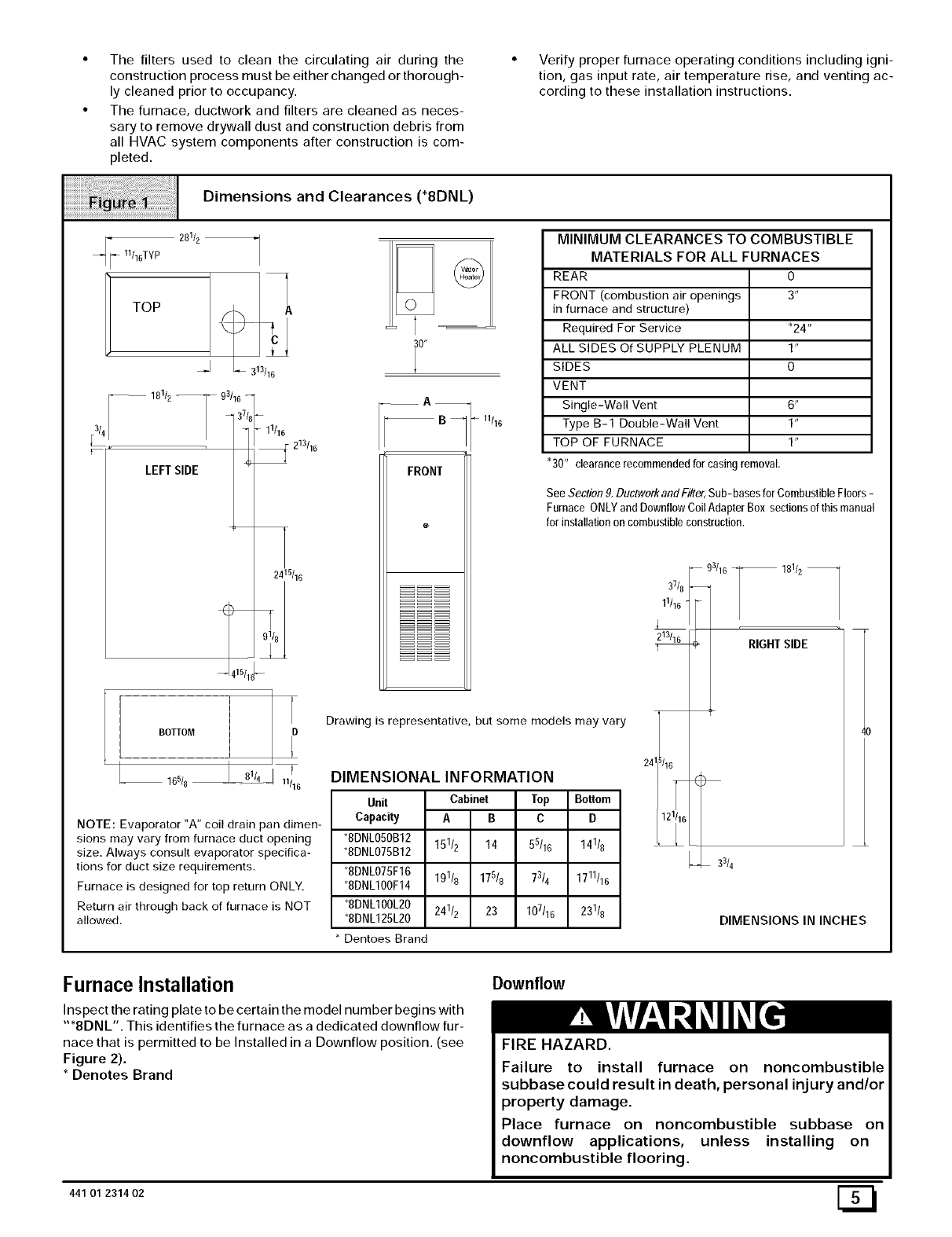
Dimensions and Clearances (*8DNL)
fl°'T i
LEFT SIDE
281/2
_-J 313116
11/16
_ 213/16
2415/16
165/8 nil 6
NOTE: Evaporator "A" coil drain pan dimen-
sions may vary from furnace duct opening
size. Always consult evaporator specifica-
tions for duct size requirements.
Furnace is designed for top return ONLY.
Return air through back of furnace is NOT
allowed.
_E
0"
FRONT
11/16
Drawing is representative, but some models may vary
DIMENSIONAL INFORMATION
Unit Cabinet Top Bottom
Capacity AB C D
*8DNL050B12 151/2 14 5
5/16 141/8
*8DNL075B12
*8DNLO75F16 191/8 175/8 73/4 1711116
*8DNL1OOF14
8DNL1OOL20 241/2 23 107116 231/8
*8DNL125L20
Dentoes Brand
MINIMUM CLEARANCES TO COMBUSTIBLE
MATERIALS FOR ALL FURNACES
REAR 0
FRONT (combustion air openings 3"
in furnace and structure)
Required For Service *24"
ALL SIDES Of SUPPLY PLENUM 1"
SIDES 0
VENT
Single-Wall Vent 6"
Type B-1 Double-Wall Vent 1"
TOP OF FURNACE 1"
"30" clearancerecommendedfor casingremoval.
See Section9.DuctworkandFiiter, Sub-basesforCombustibleFloors-
Furnace ONLYand DownflowCoilAdapterBox sectionsofthis manual
for installationon combustibleconstruction.
-- 181/2
RIGHTSIDE
24 3/16
121/16 _3
3/4
40
DIMENSIONS IN INCHES
Furnace Installation
Inspect the rating plate to be certain the model number begins with
"*8DNL". This identifies the furnace as a dedicated downflow fur-
nace that is permitted to be Installed in a Downflow position. (see
Figure 2).
* Denotes Brand
Downflow
FIRE HAZARD.
Failure to install furnace on noncombustible
subbase could result in death, personal injury and/or
property damage.
Place furnace on noncombustible subbase on
downflow applications, unless installing on
noncombustible flooring.
441 O1 231402 [_
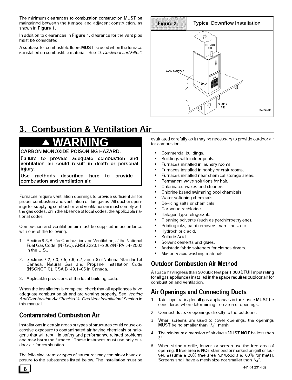
The minimum clearances to combustion construction MUST be
maintained between the furnace and adjacent construction, as
shown in Figure 1.
In addition to clearances in Figure 1, clearance for the vent pipe
must be considered.
A su bbase for combustible floors MUST be used when the furnace
is installed on combustible material. See "9. DuctworkandFilter't
GAS SUPPLY
Typical Downflow Installation
RETURN
AIR
SUPPLY
AIR
25-24-38
3. Combustion & Ventilation Air
CARBON MONOXIDE POISONING HAZARD.
evaluated carefully as it may be necessary to provide outdoor air
for combustion.
Failure to provide adequate combustion and
ventilation air could result in death or personal
injury.
Use methods described here to provide
combustion and ventilation air.
Furnaces require ventilation openings to provide sufficient air for
proper combustion and ventilation of flue gases. All duct or open-
ings for supplying combustion and ventilation air must comply with
the gas codes, or in the absence of local codes, the applicable na-
tional codes.
Combustion and ventilation air must be supplied in accordance
with one of the following:
1. Section 8.3, Air for Combustion and Ventilation, of the National
Fuel Gas Code, (NFGC), ANSI Z223.1-2002/NFPA 54-2002
in the U.S.,
2. Sections 7.2, 7.3, 7.5, 7.6, 7.7, and 7.8 of National Standard of
Canada, Natural Gas and Propane Installation Code
(NSCNGPIC), CSA B149.1-05 in Canada,
3. Applicable provisions of the local building code.
• Commercial buildings.
• Buildings with indoor pools.
• Furnaces installed in laundry rooms.
• Furnaces installed in hobby or craft rooms.
• Furnaces installed near chemical storage areas.
• Permanent wave solutions for hair.
• Chlorinated waxes and cleaners.
• Chlorine based swimming pool chemicals.
• Water softening chemicals.
• De-icing salts or chemicals.
• Carbon tetrachloride.
• Halogen type refrigerants.
• Cleaning solvents (such as perchloroethylene).
• Printing inks, paint removers, varnishes, etc.
• Hydrochloric acid.
• Sulfuric Acid.
• Solvent cements and glues.
• Antistatic fabric softeners for clothes dryers.
• Masonry acid washing materials.
Outdoor Combustion Air Method
A space having less than 50 cubic feet per 1,000 BTUH input rating
for all gas appliances installed in the space requires outdoor air for
combustion and ventilation.
When the installation is complete, check that all appliances have
adequate combustion air and are venting properly. See Venting
And Combustion Air Check in "4. Gas Vent Installation "Section in
this manual.
Air Openings and Connecting Ducts
1. Total input rating for all gas appliances in the space MUST be
considered when determining free area of openings.
Contaminated Combustion Air
Installations in certain areas or types of structures could cause ex-
cessive exposure to contaminated air having chemicals or halo-
gens that will result in safety and performance related problems
and may harm the furnace. These instances must use only out-
door air for combustion.
The following areas or types of structures may contain or have ex-
posure to the substances listed below. The installation must be
2. Connect ducts or openings directly to the outdoors.
3. When screens are used to cover openings, the openings
MUST be no smaller than 1/4" mesh.
4. The minimum dimension of air ducts MUST NOT be less than
3 _ .
When sizing a grille, louver, or screen use the free area of
opening. If free area is NOT stamped or marked on grill or lou-
ver, assume a 20% free area for wood and 60% for metal.
Screens shall have a mesh size not smaller than 1/4".
441 01 2314 02
Requirements
1. Provide the space with sufficient air for proper combustion and
ventilation of flue gases using horizontal or vertical ducts or
openings.
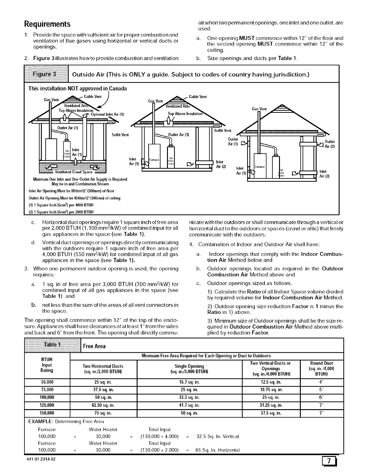
2. Figure 3 illustrates how to provide combustion and ventilation
air when two permanent openings, one inlet and one outlet, are
used.
a. One opening MUST commence within 12" of the floor and
the second opening MUST commence within 12" of the
ceiling.
b. Size openings and ducts per Table 1.
Outside Air (This is ONLY a guide. Subject to codes of country having jurisdiction.)
ThisinstallationNOTapprovedinCanada
/
GasVent • GableVent)
.,1'
;pace
MinimumOne Inletand OneOutlet AirSupply is Required
May be in andCombination Shown
Inlet AirOpening Must beWithin12"(300mm)of floor
OutletAir OpeningMust be Within12"(300mm)of ceiling
(1) 1 SquareInch (6cm2) per 4000 BTUH
(2) 1 Square Inch(6cmz) per 2000 BTUH
Gas Vent j_Gable Vent
VentilatedAttic'S.
II " SoffitVent
SoffitVent J_utlet Air(1) Outle_
II _. Air(1) [_
IF...... _G%
Air (1) _' _ _ -- Inlet
-- Air (2) Inlet
Air(1) -, i I I,n,e`
_ '_ _ _ Air (2)
c. Horizontal duct openings require I square inch of free area
per 2,000 BTUH (1,100 mmZ/kW) of combined input for all
gas appliances in the space (see Table 1).
d. Vertical duct openings or openings directlycommunicating
with the outdoors require 1 square inch of free area per
4,000 BTUH (550 mm2/kW) for combined input of all gas
appliances in the space (see Table 1).
3. When one permanent outdoor opening is used, the opening
requires:
a. 1 sq. in of free area per 3,000 BTUH (700 mm2/kW) for
combined input of all gas appliances in the space (see
Table 1) and
b. not less than the sum of the areas of all vent connectors in
the space.
The opening shall commence within 12" of the top of the enclo-
sure. Appliances shall have clearances of at least I "from the sides
and back and 6" from the front. The opening shall directly commu-
nicate with the outdoors or shall communicate through a vertical or
horizontal duct to the outdoors or spaces (crawl or attic) that freely
communicate with the outdoors.
4. Combination of Indoor and Outdoor Air shall have:
a.
b.
C.
Indoor openings that comply with the Indoor Combus-
tion Air Method below and
Outdoor openings located as required in the Outdoor
Combustion Air Method above and
Outdoor openings sized as follows.
1) Calculate the Ratio of all Indoor Space volume divided
by required volume for Indoor Combustion Air Method.
2) Outdoor opening size reduction Factor is 1 minus the
Ratio in 1) above.
3) Minimum size of Outdoor openings shall be the size re-
quired in Outdoor Combustion Air Method above multi-
plied by reduction Factor.
Area
BTUH MinimumFree Area Requiredfor EachOpeningor Ductto Outdoors
TwoVerticalDuctsor RoundDuct
Input TwoHorizontalDucts SingleOpening Openings (sq. in./4,000
Rating (sq. in./2,000BTUH) (sq. in./3,000BTUH) (sq.in./4,000 BTUH) BTUH)
50,000 25 sq. in. 16.7 sq. in, 12.5 sq. in, 4"
75,000 37,5 sq. in. 25 sq. in. 1825 sq. in. 5"
100,000 50 sq, in. 33.3 sq.in, 25 sq. in. 6"
125,000 62.50sq. in. 41.7 sq. in. 31.25 sq. in. 7"
150,000 75 sq. in. 50 sq. in. 37.5 sq. in. 7"
EXAMPLE: Determining Free Area
Furnace Water Heater Total Input
100,000 + 30,000 (130,000 + 4,000) 32.5 Sq. In. Vertical
Furnace Water Heater Total Input
100,000 + 30,000 (130,000 + 2,000) 65 Sq. In. Horizontal
441 01 231402
Indoor Combustion Air Standard and Known-Air-Infiltration Rate Methods
© NFPA&AGA
CARBON MONOXIDE POISONING HAZARD.
Failure to supply adequate combustion air could
result in death or personal injury.
Most homes will require additional air from
outdoors for combustion and ventilation. A space
with at least 50 cubic feet per 1,000 BTUH input
rating or homes with tight construction may need
outdoor air, supplied through ducts, to supplement
air infiltration for proper combustion and
ventilation of flue gases.
iiiiiiiiiiiiiiiiiiiii_i;_;:_i:_i:_i:_i:_i:_i:_i:_i:_i:_i:_i:_i:_i:_i:_:i_!!!!_ii!#_;i!_#_;i!i!;i_iiiii_ii_iiiiiiiiiii;i#;ii;ii;ii;ii;ii;i
ACH
Indoor air is permitted for combustion and ventilation, if the Stan-
dard or Known-Air-Infiltration Rate Method is used.
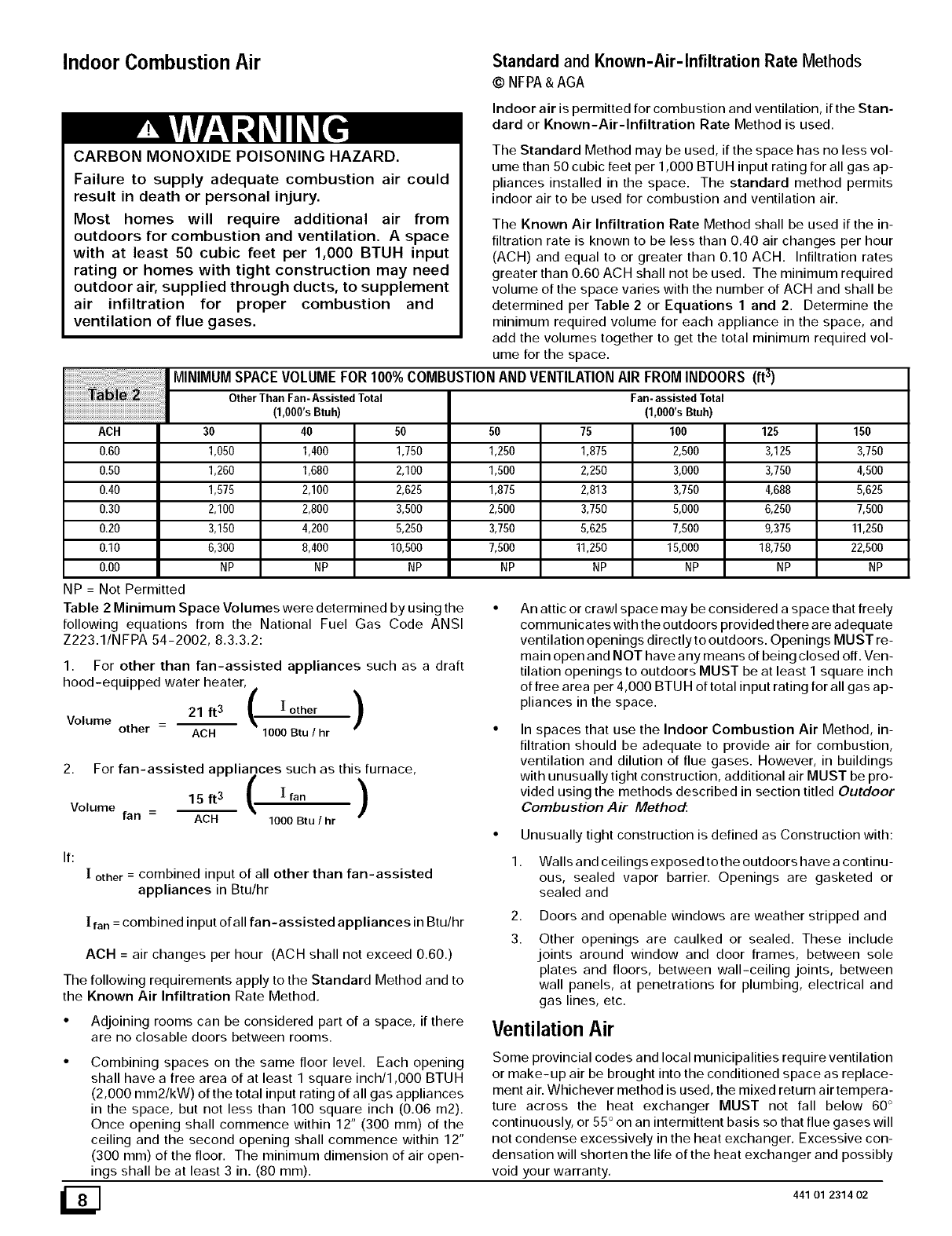
The Standard Method may be used, if the space has no less vol-
ume than 50 cubic feet per 1,000 BTUH input rating for all gas ap-
pliances installed in the space. The standard method permits
indoor air to be used for combustion and ventilation air.
The Known Air Infiltration Rate Method shall be used if the in-
filtration rate is known to be less than 0.40 air changes per hour
(ACH) and equal to or greater than 0.10 ACH. Infiltration rates
greater than 0.60 ACH shall not be used. The minimum required
volume of the space varies with the number of ACH and shall be
determined per Table 2 or Equations 1 and 2. Determine the
minimum required volume for each appliance in the space, and
add the volumes together to get the total minimum required vol-
ume for the space.
MINIMUM SPACE VOLUME FOR 100% COMBUSTION AND VENTILATION AIR FROM INDOORS (ft 3)
Other Than Fan-Assisted Total
(1,OOO'sBtuh)
30 40 50 50 125 150
0.60 1,050 1,400 1,750 1250 3,125 3,750
0.50 1,260 1,680 2,100 1,500 3,750 4,500
0.40 1,575 2,100 2,625 1,875 4,688 5,625
0.30 2,100 2,800 3,500 2,500 6250 7,500
0.20 3,150 4200 5,250 3,750 9,375 11,250
0.10 6,300 8,400 10,500 7,500 18,750 22,500
0.00 NP NP NP NP NP NP
NP = Not Permitted
Table 2 Minimum Space Volumes were determined by using the
following equations from the National Fuel Gas Code ANSI
Z223.1/NFPA 54-2002, 8.3.3.2:
1. For other than fan-assisted appliances such as a draft
hood-equipped water heater,
21 ft 3 ( ! other )
Volume other - ACH 1000 Btu /hr
2. For fan-assisted appliances such as this furnace,
15ft3 ( Iran )
Volume fan =ACH 1000 Btu !hr
[ other =combined input of all other than fan-assisted
appliances in Btu/hr
[ ran = combined input of all fan-assisted appliances in Btu/hr
If:
ACH = air changes per hour (ACH shall not exceed 0.60.)
The following requirements apply to the Standard Method and to
the Known Air Infiltration Rate Method.
•Adjoining rooms can be considered part of a space, if there
are no closable doors between rooms.
•Combining spaces on the same floor level. Each opening
shall have a free area of at least 1 square inch/1,000 BTUH
(2,000 mm2/kW) of the total input rating of all gas appliances
in the space, but not less than 100 square inch (0.06 m2).
Once opening shall commence within 12" (300 mm) of the
ceiling and the second opening shall commence within 12"
(300 mm) of the floor. The minimum dimension of air open-
ings shall be at least 3 in. (80 mm).
Fan- assistedTotal
(1,000'sBtuh)
75 100
1,875 2,500
2,250 3,000
2,813 3,750
3,750 5,000
5,625 7,500
11,250 15,000
NP NP
An attic or crawl space may be considered a space that freely
communicates with the outdoors provided there are adequate
ventilation openings directly to outdoors. Openings MUST re-
main open and NOT have any means of being closed off. Ven-
tilation openings to outdoors MUST be at least I square inch
of free area per 4,000 BTUH of total input rating for all gas ap-
pliances in the space.
In spaces that use the Indoor Combustion Air Method, in-
filtration should be adequate to provide air for combustion,
ventilation and dilution of flue gases. However, in buildings
with unusually tight construction, additional air MUST be pro-
vided using the methods described in section titled Outdoor
Combustion Air Method:
•Unusually tight construction is defined as Construction with:
1. Walls and ceilings exposed to the outdoors have a continu-
ous, sealed vapor barrier. Openings are gasketed or
sealed and
2,
3.
Doors and openable windows are weather stripped and
Other openings are caulked or sealed. These include
joints around window and door frames, between sole
plates and floors, between wall-ceiling joints, between
wall panels, at penetrations for plumbing, electrical and
gas lines, etc.
Ventilation Air
Some provincial codes and local municipalities require ventilation
or make-up air be brought into the conditioned space as replace-
ment air. Whichever method is used, the mixed return air tempera-
ture across the heat exchanger MUST not fall below 60 °
continuously, or 55 ° on an intermittent basis so that flue gases will
not condense excessively in the heat exchanger. Excessive con-
densation will shorten the life of the heat exchanger and possibly
void your warranty.
441 O1 2314 02
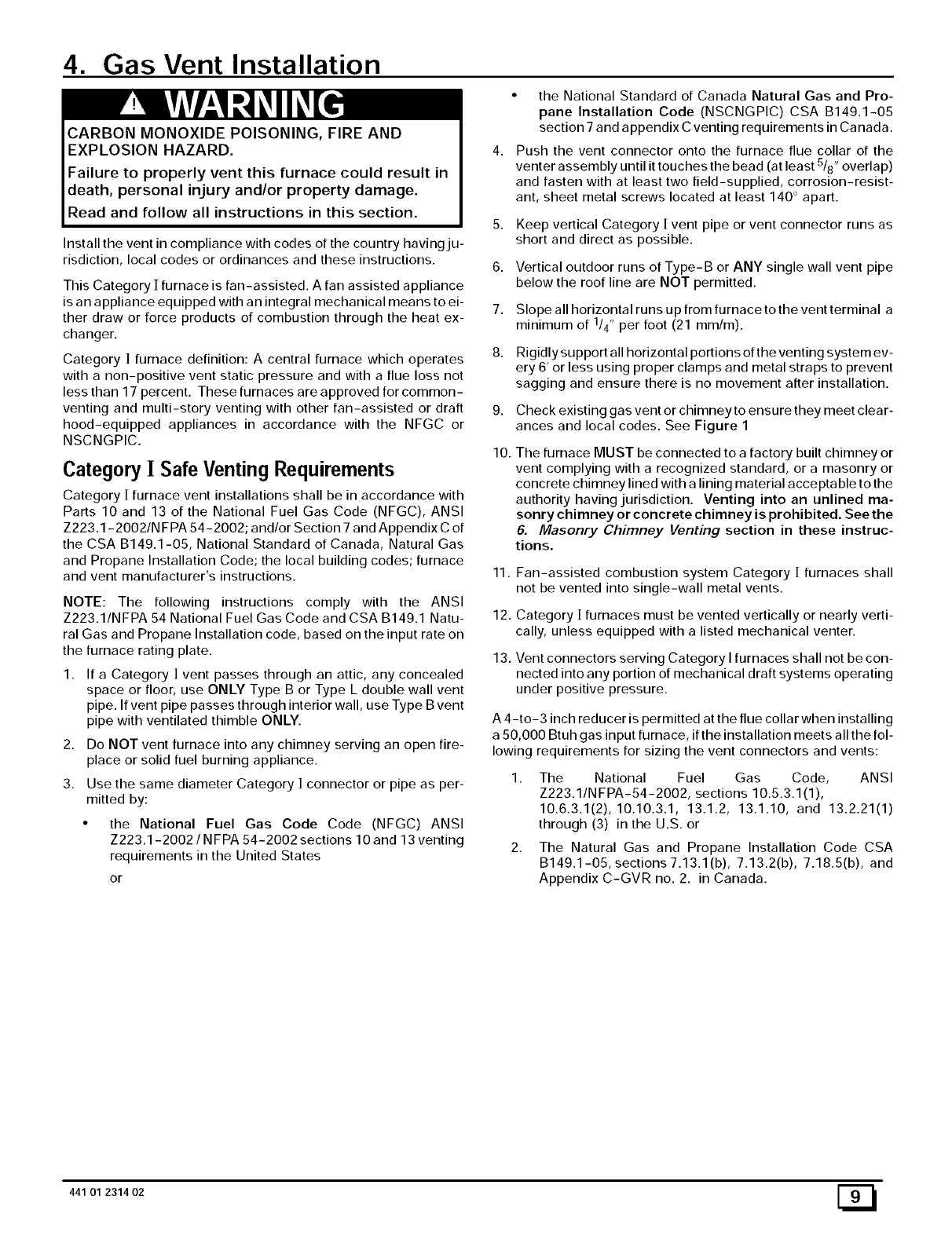
4. Gas Vent Installation
CARBON MONOXIDE POISONING, FIRE AND
EXPLOSION HAZARD.
Failure to properly vent this furnace could result in
death, personal injury and/or property damage.
Read and follow all instructions in this section.
Install the vent in compliance with codes of the country havingju-
risdiction, local codes or ordinances and these instructions.
•the National Standard of Canada Natural Gas and Pro-
pane Installation Code (NSCNGPIC) CSA B149.1-05
section 7 and appendix C venting requirements in Canada.
Push the vent connector onto the furnace flue collar of the
venter assembly until it touches the bead (at least 5/8" overlap)
and fasten with at least two field-supplied, corrosion-resist-
ant, sheet metal screws located at least 140 ° apart.
5. Keep vertical Category [ vent pipe or vent connector runs as
short and direct as possible.
6,
7.
This Category ] furnace is fan-assisted. A fan assisted appliance
is an appliance equipped with an integral mechanical means to ei-
ther draw or force products of combustion through the heat ex-
changer.
Category ] furnace definition: A central furnace which operates 8.
with a non-positive vent static pressure and with a flue loss not
less than 17 percent. These furnaces are approved for common-
venting and multi-story venting with other fan-assisted or draft 9.
hood-equipped appliances in accordance with the NFGC or
NSCNGPIC. 10.
Category [ Safe Venting Requirements
Category [ furnace vent installations shall be in accordance with
Parts 10 and 13 of the National Fuel Gas Code (NFGC), ANSI
Z223.1-2002/N FPA 54-2002; and/or Section 7 and Appendix C of
the CSA B149.1-05, National Standard of Canada, Natural Gas
and Propane Installation Code; the local building codes; furnace
and vent manufacturer's instructions.
NOTE: The following instructions comply with the ANSI
Z223.1/NFPA 54 National Fuel Gas Code and CSA B149.1 Natu-
ral Gas and Propane Installation code, based on the input rate on
the furnace rating plate.
If a Category ]vent passes through an attic, any concealed
space or floor, use ONLY Type B or Type L double wall vent
pipe. If vent pipe passes through interior wall, use Type B vent
pipe with ventilated thimble ONLY.
Do NOT vent furnace into any chimney serving an open fire-
place or solid fuel burning appliance.
Use the same diameter Category ]connector or pipe as per-
mitted by:
• the National Fuel Gas Code Code (NFGC) ANSI
Z223.1-2002 /NFPA 54-2002 sections 10 and 13 venting
requirements in the United States
1,
2,
3.
or
Vertical outdoor runs of Type-B or ANY single wall vent pipe
below the roof line are NOT permitted.
Slope all horizontal runs up from furnace to the vent terminal a
minimum of 1/4" per foot (21 ram/m).
Rigidly support all horizontal portions of the venting system ev-
ery 6' or less using proper clamps and metal straps to prevent
sagging and ensure there is no movement after installation.
Check existing gas vent or chimney to ensure they meet clear-
ances and local codes. See Figure 1
The furnace MUST be connected to a factory built chimney or
vent complying with a recognized standard, or a masonry or
concrete chimney lined with a lining material acceptable to the
authority having jurisdiction. Venting into an unlined ma-
sonry chimney or concrete chimney is prohibited. See the
6. Masonry Chimney Venting section in these instruc-
tions.
11.
12.
13.
Fan-assisted combustion system Category [furnaces shall
not be vented into single-wall metal vents.
Category [furnaces must be vented vertically or nearly verti-
cally, unless equipped with a listed mechanical venter.
Vent connectors serving Category I furnaces shall not be con-
nected into any portion of mechanical draft systems operating
under positive pressure.
A 4-to-3 inch reducer is permitted at the flue collar when installing
a 50,000 Btuh gas input furnace, if the installation meets all the fol-
lowing requirements for sizing the vent connectors and vents:
1. The National Fuel Gas Code, ANSI
Z223.1/NFPA-54-2002, sections 10.5.3.1(1),
10.6.3.1(2), 10.10.3.1, 13.1.2, 13.1.10, and 13.2.21(1)
through (3) in the U.S. or
2. The Natural Gas and Propane Installation Code CSA
B149.1-05, sections 7.13.1 (b), 7.13.2(b), 7.18.5(b), and
Appendix C-GVR no. 2. in Canada.
441 01 2314 02 [_
Venting and Combustion Air Check
NOTE: When an existing Category I furnace is removed or re-
placed, the original venting system may no longer be sized to prop-
erly vent the attached appliances, and to make sure there is
adequate combustion air for all appliances, MAKE THE FOL-
LOWING CHECK.
CARBON MONOXIDE POISONING HAZARD
Failure to follow the steps outlined below for each
appliance connected to the venting system being placed
into operation, could result in carbon monoxide
poisoning or death:
The following steps shall be followed for each appliance
connected to the venting system being placed into
operation, while all other appliances connected to the
venting system are not in operation:
1 .Seal any unused openings in the venting system.
2.Inspect the venting system for proper size and horizontal
pitch, as required in the National Fuel Gas Code, ANSI
Z223. 1/NFPA 54 or CSA B 149. 1, Natural Gas a nd Propane
Installation Code and these instructions. Determine that
there is no blockage or restriction, leakage, corrosion and
other deficiencies which could cause an unsafe condition.
3.As far as practical, close all building doors and windows and
all doors between the space in which the appliance(s)
connected to the venting system are located and other
spaces of the building.
4.Close fireplace dampers.
5.Turn on clothes dryers and any appliance not connected to
the venting system. Turn on any exhaust fans, such as
range hoods and bathroom exhausts, sothey are operating
at maximum speed. Do not operate a summer exhaust fan.
6.Follow the lighting instructions. Place the appliance being
inspected into operation. Adjust the thermostat so
appliance is operating continuously.
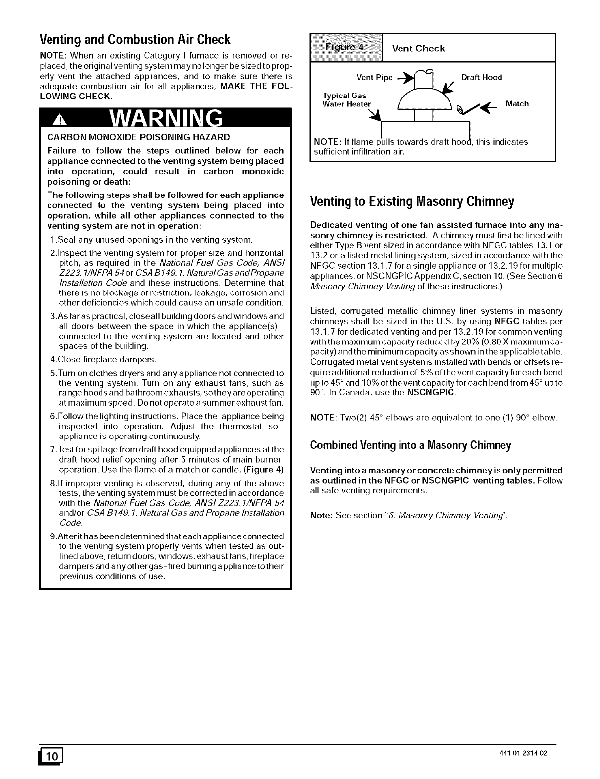
7.Test for spillage from draft hood equipped appliances at the
draft hood relief opening after 5 minutes of main burner
operation. Use the flame of a match or candle. (Figure 4)
8.If improper venting is observed, during any of the above
tests, the venting system must be corrected in accordance
with the National Fuel Gas Code, ANSI Z223.1/NFPA 54
and/or CSA B149, 1, Natural Gas and Propane Installation
Code.
9.After it has been determined that each a pplia nce connected
to the venting system properly vents when tested as out-
lined above, return doors, windows, exhaust fans, fireplace
dampers and any other gas-fired burning appliance to their
previous conditions of use.
Vent Check
VentPipe _1 I A/ Draft Hood
Typical Gas
Water Heater
! !
NOTE: If Elaine p_ulls towards draft hoo_, this indicates
sufficient infiltration air.
Venting to Existing Masonry Chimney
Dedicated venting of one fan assisted furnace into any ma-
sonry chimney is restricted. A chimney must first be lined with
either Type B vent sized in accordance with NFGC tables 13.1 or
13.2 or a listed metal lining system, sized in accordance with the
NFGC section 13.1.7 for a single appliance or 13.2.19 for multiple
appliances, or NSCNGPIC Appendix C, section 10. (See Section 6
Masonry Chimney Venting of these instructions.)
Listed, corrugated metallic chimney liner systems in masonry
chimneys shall be sized in the U.S. by using NFGC tables per
13.1.7 for dedicated venting and per 13.2.19 for common venting
with the maximum capacity reduced by 20% (0.80 X maximum ca-
pacity) and the minimum capacity as shown in the applicable table.
Corrugated metal vent systems installed with bends or offsets re-
quire additional reduction of 5% of the vent capacity for each bend
up to 45 ° and 10% of the vent capacity for each bend from 45 ° up to
90 °. In Canada, use the NSCNGPIC.
NOTE: Two(2) 45 ° elbows are equivalent to one (1) 90 ° elbow.
Combined Venting into a Masonry Chimney
Venting into a masonry or concrete chimney is only permitted
as outlined in the NFGC or NSCNGPIC venting tables. Follow
all safe venting requirements.
Note: See section "6. Masonry Chimney Venting'.
_] 441 01 2314 02
5. Horizontal Venting
Category I Furnaces With External Power
Venters
In order to maintain a Category ]classification of fan-assisted fur-
naces when vented horizontally with sidewall termination, a power
venter is REQUIRED to maintain a negative pressure in the vent-
ing system.
In the U.S.: Per the NFGC, a listed power venter may be used,
when approved by the authority having jurisdiction.
Vent Termination
Venting Through a Non-Combustible and
Combustible Wall
Consult External Power Venter manufacturer instructions.
Select the power venter to match the Btuh input of the furnace be-
ing vented. Follow all of the power venter manufacturer's installa-
tion requirements included with the power venter for:
• venting installation,
• vent terminal location,
In Canada: Only power venters approved by the appliance
manufacturer and where allowed by the authority having jurisdic-
tion may be used.
Please consult the Fields Controls Co. or Tjernlund Products, Inc.
for power venters certified for use with this furnaces.
• preventing blockage by snow,
• protecting building materials from degradation by flue gases,
• see Figure 5 for required vent termination.
NOTE: It is the responsibility of the installer to properly terminate
the vent and provide adequate shielding. This is essential in order
to avoid water/ice damage to building, shrubs and walkways.
441 01 2314 02 [_
iiiiiiiiiiiiiiiiii;ii_;;_i:_i:_i;!;!:;!_i_ii!_!ii_i:_:i::_;_i_!_!_i!ii!ii!ii!ii!ii!ii!ii!ii!ii!ii!ii!_i!;iiiiiiiii_iiiiiiiiiiiiiiiiiiiiiii_!!!;!_i¸ii;ilililiiiiiiiiiiiiiiiiiiiiiiii_i_i_ii!!!iiiii
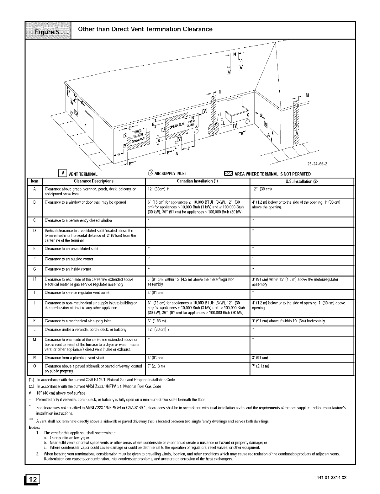
Other than Direct Vent Termination Clearance
r_ VENT TERMINAL
Item Clearance Descriptions
A Clearance above grade, veranda, porch, deck, balcony, or
anticipated snow level
B Clearance to a window or door that may be opened
C
D
E
F
G
H
I
J
K
L
M
N
0
Clearance to a permanently closed window
Vertical clearance to a ventilated soffit located above the
terminal within a horizontal distance of 2' (61cm) from the
centedine of the terminal
Clearance to an unventilated soffit
Clearance to an outside corner
Clearance to an inside corner
Clearance to each side of the centefline extended above
electrical meter or gas service regulator assembly
Clearance to service regulator vent outlet
Clearance to non-mechanical air supply inlet to building or
the combustion air inlet to any other appliance
Clearanceto amechanicalair supplyinlet
Clearanceundera veranda,porch,deck,or balcony
Clearance to each side of the centefline extended above or
below vent terminal of the furnace to a dryer or water heater
vent, or other appliance's direct vent intake or exhaust.
Clearance from a plumbing vent stack
Clearanceabovea pavedsidewalkor paveddrivewaylocated
on publicproperty.
(_ AIRSUPPLYINLET
Canadian Installation(1)
12" (30cm)#
6" (lfi cm) for appliances_<10,000BTUH(3kW), 12" (30
cm) for appliances> 10,000Btub (3kW) and _<100,000Btub
(30 kW),36" (01 cm) for appliances> 100,000Btuh (30kW)
3' (91 cm) within 15' (4.5 m) above the meter/regulator
assembly
3' (01 cm)
6" (15cm)forappliances_<lO,OOOBTUH (3kW),12" (30
cm) for appliances > 10,000 Btuh (3 kW) and _<100,000 Btuh
(30 kW), 36" (01 cm) for appliances > 100,000 Btuh (30 kW)
6' (1.83 m)
12" (30 cm) +
3' (01cm)
7' (2.13m)
AREA WHERE TERMINAL IS NOT PERMITED
U.S. Installation (2)
12" (30 cm)
4' (1.2 m) below or to the side of the opening. 1' (30 cm)
above lhe opening.
3' (91 cm) within 15' (4.5 m) above the meter/regulator
assembly
4' (1.2 m) below or to the side of opening: 1' (30 cm) above
opening.
3' (91 cm) above if within 10' (3m) horizontally
3' (01cm)
7' (2.13m)
(1.) In accordance with the current CSA B149.1, Natural Gas and Propane Installation Code
(2,) In accordance with the currem ANSI Z223.1/NFPA fi4, National Fuel Gas Code
#18" (46 cm) above roof surface
+Permitted only if veranda, porch, deck, or balcony is fully open on a minimum of two sides beneath the floor.
For clearances not specified in ANSI Z223.1/NFPA 54 or CSA B140.1, clearances shall be in accordance with local installation codes and the requiremenls of the gas supplier and the manufacture's
installation instructions.
A vent shall nol terminate directly above a sidewalk or paved driveway that is located between two single family dwellings and serves both dwellings.
Notes:
1, The vent for this appliance shall not terminate
a. Over public walkways; or
b. Near soffit vents or crawl space vents or other areas where condensate or vapor could create a nusiance or hazard or property damage; or
c. Where condensate vapor could cause damage or could be detrimental to the operafion of regulators, relief valves, or other equipment.
2. When locating vent terminations, consideration must be given to prevailing winds, location, and other conditions which may cause recirculation of the combusfiob products of adjacent vents.
Recirculafion can cause poor combustion, inlet condensate problems, and accelerated corrosion of the heat exchangers.
441 01 2314 02
6. Masonry Chimney Venting
Chimney Inspection
All masonry chimney construction must conform to Standard
ANSI/NFPA 211-2003 and to any state or local codes applicable.
The chimney must be in good condition and a complete chimney
inspection must be conducted prior to furnace installation. If the in-
spection reveals damage or abnormal conditions, make neces-
sary repairs or seek expert help. See "The Chimney Inspection
Chart" Figure 6. Measure inside area of tile-liner and exact height
of chimney from the top of the chimney to the highest appliance
flue collar or drafthood outlet.
Connector Type
To reduce flue gas heat loss and the chance of condensate prob-
lems, the vent connector must be double-wall Type B vent.
Venting Restrictions for Chimney Types
Interior Chimney - has no sides exposed to the outdoors below
the roofline. All installations can be single furnace or common
vented with another draft hood equipped Category ]appliance.
Exterior Chimney -has one or more sides exposed to the out-
doors below the roof line. All installations with a 99% Winter De-
sign Temperature* below 17°F must be common vented only with
a draft hood equipped Category I appliance.
The99%WinterDesignDry-Bulb(db)temperaturesarefoundinthe1993ASHRAE
FundamentalsHandbook,Chapter24, Table1 (UnitedStates)and 2 (Canada),or
usethe 99.6%heatingdbtemperaturesfound inthe1997or2001ASHRAEFunda-
Ifa claytile-lined masonry chimney is being used and it is exposed
to the outdoors below the roof line, relining might be required.
Chimneys shall conform to the Standard for Chimneys, Fire-
places, Vents, and Solid Fuel Burning Appliances ANSI/NFPA
211-2003 in the United States and to a Provincial or Territorial
Building Code in Canada (in its absence, the National Building
Code of Canada) and must be in good condition.
U.S.A.- Refer to Sections 13.1.9 or 13.2.20 of the NFGC or the au-
thority having jurisdiction to determine whether relining is required.
If relining is required, use a properly sized listed metal liner,
Type-B vent, or a listed alternative venting design.
This model (*8DNL) is NOT listed for use with Chimney Adapter
kits. A multi-position furnace in the downflow position that is listed
for use with one of the Chimney Adapter Kits NAHAOOIDH or
NAHAOO2DH may be used with a masonry chimney.
Canada (and U.S.A.)-This furnace is permitted to be vented into a
clay tile-lined masonry chimney that is exposed to the outdoors
below the roof line, provided:
1. Vent connector is Type-B double-wall, and
2. This furnace is common vented with at least 1 draft hood-
mentalsHandbook,ClimaticDesign Informationchapter,Table1A (UnitedStates)
and 2A (Canada).
CARBON MONOXIDE POISONING, FIRE AND
EXPLOSION HAZARD.
Failure to properly vent this furnace could result in
death, personal injury and/or property damage.
These furnaces are CSA (formerly AGA and CGA
design-certified for venting into exterior clm
tile-lined masonry chimneys with a factory accesso
ry Chimney Adapter Kit. Refer to the furnace rating
31atefor correct kit usage. The Chimney Adapter Kits
are for use with ONLY furnaces having a Chimne_
Adapter Kit number marked on the furnace ratin i
plate.
equipped appliance, and
The combined appliance input rating is less than the maxi-
mum capacity given in Table A, and
The input rating of each space-heating appliance is greater
than the minimum input rating given in Table B for Masonry
Chimneys for the local 99% Winter Design Temperature.
Chimneys having internal areas greater than 38 square
inches require furnace input ratings greater than the input
ratings of these furnaces. See footnote at bottom of Table B,
and
5. The authority having jurisdiction approves.
If all of these conditions cannot be met, an alternative venting de-
sign shall be used, such as a listed chimney-lining system, or a
Type-B vent.
441 01 2314 02 [_
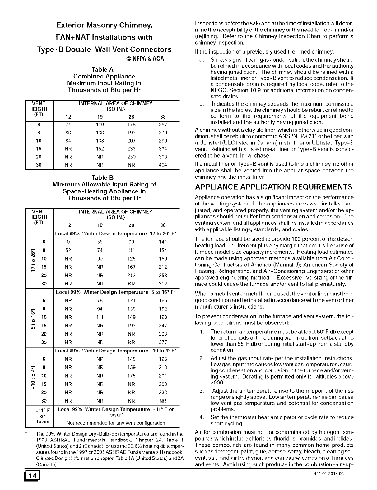
Exterior Masonry Chimney,
FAN+NAT Installations with
Type-B Double-Wall Vent Connectors
VENT
HEIGHT
(FT)
6
8
10
15
20
30
VENT
HEIGHT
(FT)
6
8
o 10
2O
30
_" 10
0
,_ 15
20
30
6
8
o 10
o is
i
2O
©NFPA& AGA
Table A-
Combined Appliance
Maximum Input Rating in
Thousands of Btu per Hr
INTERNAL AREA OF
(SQ IN.)
12 19 28
74 119 178
80 130 193
84 138 207
NR 152 233
NR NR 250
NR NR NR
CHIMNEY
Table B-
Minimum Allowable Input Rating of
Space-Heating Appliance in
Thousands of Btu per Hr
38
257
279
299
334
368
404
INTERNAL AREA OF CHIMNEY
(SQ IN.)
12 19 28 38
Local 99% Winter Design Temperature: 17 to 26 ° F*
0 55 99 141
52 74 111 154
NR 90 125 169
NR NR 167 212
NR NR 212 258
NR NR NR 362
Local 99% Winter Design Temperature: 5 to 16° F*
NR 78 121 166
NR 94 135 182
NR 111 149 198
NR NR 193 247
NR NR NR 293
Inspections before the sale a nd at the time of installation will deter-
mine the acceptability of the chimney or the need for repair and/or
(re)lining. Refer to the Chimney Inspection Chart to perform a
chimney inspection.
If the inspection of a previously used tile-lined chimney:
a. Shows signs of vent gas condensation, the chimney should
be relined in accordance with local codes and the authority
having jurisdiction. The chimney should be relined with a
listed metal liner or Type-B vent to reduce condensation. If
a condensate drain is required by local code, refer to the
NEGC, Section 10.9 for additional information on conden-
sate drains.
b. Indicates the chimney exceeds the maximum permissible
size in the tables, the chimney should be rebuilt or relined to
conform to the requirements of the equipment being
installed and the authority having jurisdiction.
A chimney without a clay tile liner, which is otherwise in good con-
dition, shall be rebuilt to conform to AN SI/N FPA 211 or be lined with
a UL listed (ULC listed in Canada) metal liner or UL listed Type-B
vent. Relining with a listed metal liner or Type-B vent is consid-
ered to be a vent-in-a-chase.
If a metal liner or Type-B vent is used to line a chimney, no other
appliance shall be vented into the annular space between the
chimney and the metal liner.
APPLIANCE APPLICATION REQUIREMENTS
NR NR NR 377
Local 99% Winter Design Temperature: -10 to 4° F*
NR NR 145 196
NR NR 159 213
NR NR 175 231
NR NR NR 283
NR NR NR 333
NR NR NR NR
Appliance operation has a significant impact on the performance
of the venting system. If the appliances are sized, installed, ad-
justed, and operated properly, the venting system and/or the ap-
pliances should not suffer from condensation and corrosion. The
venting system and all appliances shall be installed in accordance
with applicable listings, standards, and codes.
30
-11 ° F Local 99% Winter Design Temperature: -11 ° F or
or lower*
lower Not recommended for any vent configuration
The 99% Winter Design Dry-Bulb (db) temperatures are found in the
1993 ASHRAE Fundamentals Handbook, Chapter 24, Table 1
(United States) and 2 (Canada), or use the 99.6% beating db temper-
atures found in the 1997 or 2001 ASHRAE Fundamentals Handbook,
Climatic Design Information chapter, Table 1A (United States) and 2A
(Canada).
The furnace should be sized to provide 100 percent of the design
heating load requirement plus any margin that occurs because of
furnace model size capacity increments. Heating load estimates
can be made using approved methods available from Air Condi-
tioning Contractors of America (Manual J); American Society of
Heating, Refrigerating, and Air-Conditioning Engineers; or other
approved engineering methods. Excessive oversizing of the fur-
nace could cause the furnace and/or vent to fail prematurely.
When a metal vent or metal liner is used, the vent or liner must be in
good condition and be installed in accordance with the vent or liner
manufacturer's instructions.
To prevent condensation in the furnace and vent system, the fol-
lowing precautions must be observed:
1. The return-air temperature must be at least 60°F db except
for brief periods of time during warm-up from setback at no
lower than 55°F db or during initial start-up from a standby
condition.
Adjust the gas input rate per the installation instructions.
Low gas input rate causes low vent gas temperatures, ca us-
ing condensation and corrosion in the furnace and/or vent-
ing system. Derating is permitted only for altitudes above
2000'.
3. Adjust the air temperature rise to the midpoint of the rise
range or slightly a hove. Low air temperature rise ca n ca use
low vent gas temperature and potential for condensation
problems.
4. Set the thermostat heat anticipator or cycle rate to reduce
short cycling.
Air for combustion must not be contaminated by halogen com-
pounds which include chlorides, fluorides, bromides, and iodides.
These compounds are found in many common home products
such as detergent, paint, glue, aerosol spray, bleach, cleaning sol-
vent, salt, and air freshener, and can cause corrosion of furnaces
and vents. Avoid using such products in the combustion-air sup-
441 01 2314 02
ply. Furnace use during construction of the building could cause
the furnace to be exposed to halogen compounds, causing prema-
ture failure of the furnace or venting system due to corrosion.
Vent dampers on any appliance connected to the common vent
can cause condensation and corrosion in the venting system. Do
not use vent dampers on appliances common vented with this fur-
Race.
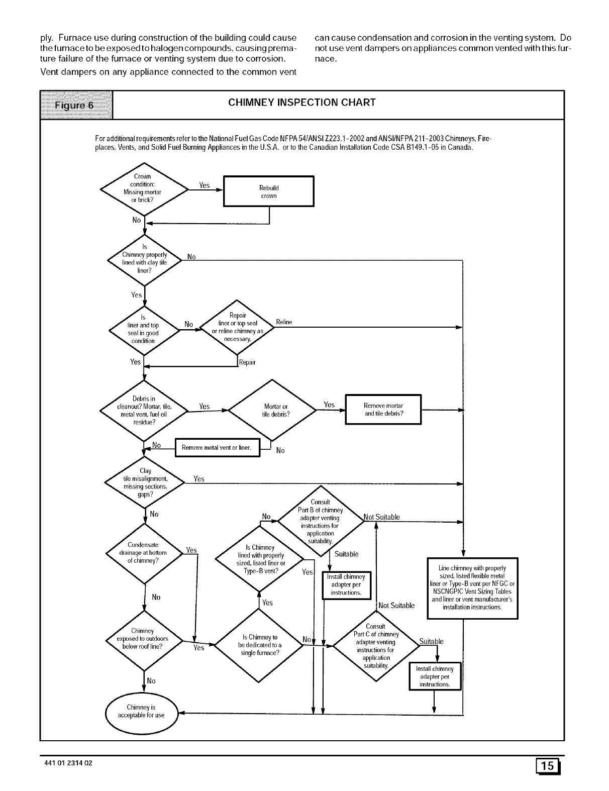
CHIMNEY INSPECTION CHART
Foradditionalrequirementsreferto the NationalFuelGas CodeNFPA54/ANSIZ223.1-2002 andANSIINFPA211-2003Chimneys,Fire-
places,Vents,and Solid Fuel BurningAppliancesin the U.S.A. orto the Canadian InstallationCode CSAB149.1-05 in Canada.
condition: Rebuild
Missing mortar crown
orbrick? I
,_ withclay tile No
Yes
linerand top
seal in good
Reline
lineror top seal
orreline chimnei'as_
IRepair
metalvent, fuel oil
residue?
Mortar or Remove mortar
file debris? and tile debris?
Remove metal vent or liner.
_,,_stile n_isalignrnent, Yes p-
ing sections,
No No adapter venting Not Suitable
- _ instructions for /i,
/_ \ application/
Condensate /,sObi e, " tab,iy
drainage atbottom _ < _:_r _'-]Vl Suitable
ofchimney? _ TvDe-Bven_/vo_[ _ Linechim!ywitbpropedy
"' /'_[ InstallchimneyI sized,listedflexiblemetal
_. /Iadaprerper IlinerorType-BventperNFGCor
T. I_ NSCNGPICVentSizingTables
No Tv^_ Iandlinerorventmanufacturer's
._ [/_ Not Suitable instal]ationinstructions.
/_,/Consul__
Chimney .,/IsChimnevto _ t,,_J_ /PartCofchimney_
_.3,_ _ _2_uT ' _ adapter venting S_le
be,owroof,ine? Yes _. U_nUalUe'_u;nace./ j_rT-"_, _ ,nstructionsfor |
\ _ /I\ apl_!ica!i°n /_'
/[ _,uitability/ I installchimney
441 01 2314 02 [_
7. Gas Supply and Piping
CARBON MONOXIDE POISONING, FIRE AND
EXPLOSION HAZARD.
Failure to follow safety warnings exactly could
result in death, personal injury and/or property
damage.
Models designated for Natural Gas are to be used
with Natural Gas ONLY, unless properly
converted to use with LP gas.
Gas Supply Requirements
• Use only the Type of gas approved for this furnace. See rating
plate for approved gas type.
• Gas input must not exceed the rated input shown on the rating
plate. Overfiring will result in failure of heat exchanger and
cause dangerous operation.
Do not allow minimum supply pressure to vary downward. Do-
ing so will decrease input to furnace. Refer to Table 3 for gas
supply. Refer to Table 5 or Table 6 for manifold pressures.
i I Pressures
Gas Type Supply Pressure
Recommended Max.
Natural 7" 14"
Propane 11" 14"
Min,
4,5"
11"
Gas Piping Requirements
NOTE: The gas supply line must be installed bya qualified service
technician in accordance with all building codes.
NOTE: In the state of Massachusetts.
1,
2.
a. Gas supply connections MUST be performed by a li-
censed plumber or gas fitter).
b. When flexible connectors are used, the maximum length
shall not exceed 36" (915 ram).
c. When lever handle type manual equipment shutoff valves
are used, they shall be T-handle valves.
d. The use of copper tubing for gas piping is NOT approved.
Install gas piping in accordance with local codes, or in the ab-
sence of local codes, the applicable national codes.
It is recommended that a manual equipment shutoff valve be
installed in the gas supply line outside the furnace. Locate
valve as close to the furnace as possible where it is readily ac-
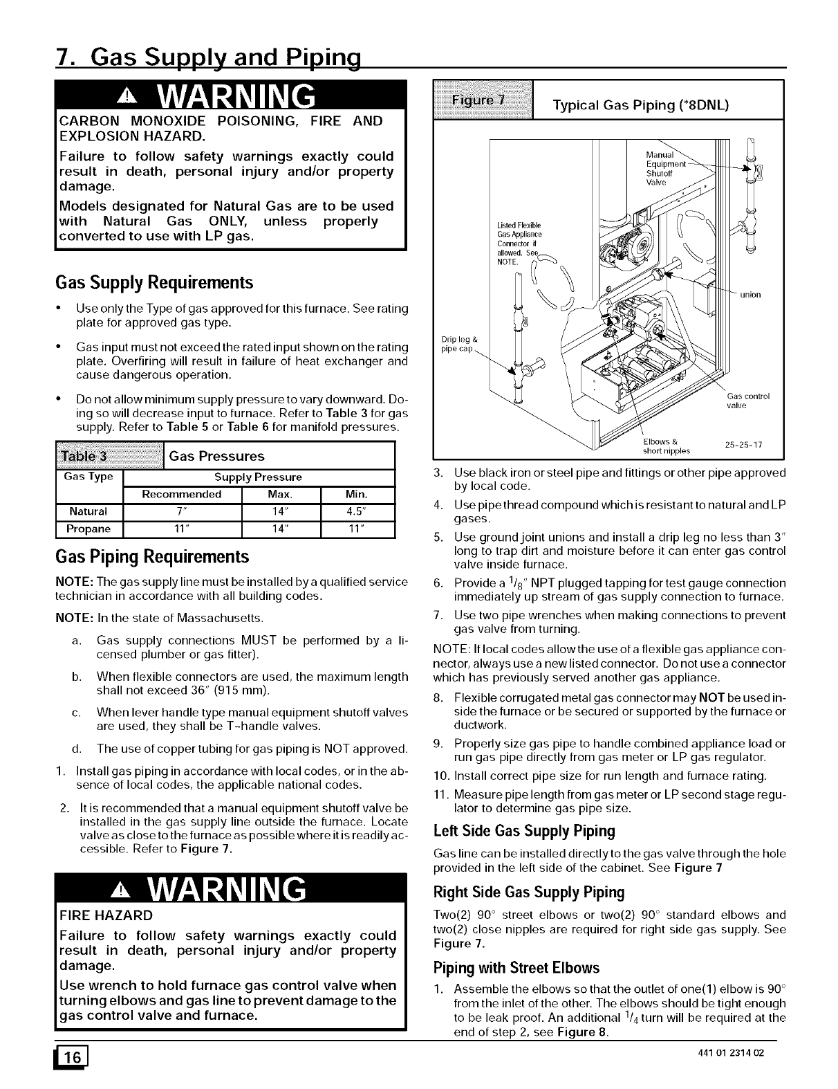
cessible. Refer to Figure 7.
Typical Gas Piping ('8DNL)
Drip leg &
pipe cap _.
Listed Flexible
Gas Appliance
Connector if
11o4
IO] Se_c%
union
\Gas control
valve
Elbows & 25-25-17
short nipples
3. Use black iron or steel pipe and fittings or other pipe approved
by local code.
4. Use pipe thread compound which is resistant to natural and LP
gases.
5. Use ground joint unions and install a drip leg no less than 3"
long to trap dirt and moisture before it can enter gas control
valve inside furnace.
6. Provide a 118" NPT plugged tapping for test gauge connection
immediately up stream of gas supply connection to furnace.
7. Use two pipe wrenches when making connections to prevent
gas valve from turning.
NOTE: If local codes allow the use of a flexible gas appliance con-
nector, always use a new listed connector. Do not use a connector
which has previously served another gas appliance.
8. Flexible corrugated metal gas connector may NOT be used in-
side the furnace or be secured or supported by the furnace or
ductwork.
9. Properly size gas pipe to handle combined appliance load or
run gas pipe directly from gas meter or LP gas regulator.
10. Install correct pipe size for run length and furnace rating.
11. Measure pipe length from gas meter or LP second stage regu-
lator to determine gas pipe size.
Left Side Gas Supply Piping
Gas line can be installed directly to the gas valve through the hole
provided in the left side of the cabinet. See Figure 7
FIRE HAZARD
Failure to follow safety warnings exactly could
result in death, personal injury and/or property
damage.
Use wrench to hold furnace gas control valve when
turning elbows and gas line to prevent damage to the
gas control valve and furnace.
Right Side Gas Supply Piping
Two(2) 90 ° street elbows or two(2) 90 ° standard elbows and
two(2) close nipples are required for right side gas supply. See
Figure 7.
Piping with Street Elbows
1. Assemble the elbows so that the outlet of one(l) elbow is 90 °
from the inlet of the other. The elbows should be tight enough
to be leak proof. An additional 1/4 turn will be required at the
end of step 2, see Figure 8.
_] 441 01 2314 02
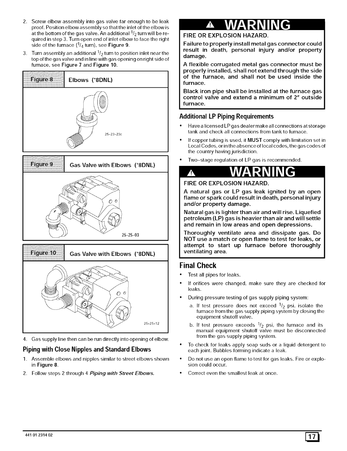
2. Screw elbow assembly into gas valve far enough to be leak
proof. Position el bow assembly so that the inlet of the el bow is
at the bottom of the gas valve. An additional 1/2 turn will be re-
quired in step 3. Turn open end of inlet elbow to face the right
side of the furnace (1/4 turn), see Figure 9.
3. Turn assembly an additional 1/2 turn to position inlet near the
top of the gas valve and in line with gas opening on right side of
furnace, see Figure 7 and Figure 10.
iiiiiiiiiiiiiiiiiiiiiiiii:iiiiiii;;;i_i¸!!iii!ilil!!!!!!!i!!!iiiii¸;I i!iliiii¸i¸Ii;¸ E,bows *aDNL
25-23-23c
Gas Valve with Elbows (*8DNL)
25-25-03
Gas Valve with Elbows (*aDNL)
25-25-12
4. Gas supply line then can be run directly into opening of elbow.
Piping with Close Nipples and Standard Elbows
1. Assemble elbows and nipples similar to street elbows shown
in Figure 8.
2. Follow steps 2 through 4 Piping with Street Elbows.
FIRE OR EXPLOSION HAZARD.
Failure to properly install metal gas connector could
result in death, personal injury and/or property
damage.
A flexible corrugated metal gas connector must be
properly installed, shall not extend through the side
of the furnace, and shall not be used inside the
furnace.
Black iron pipe shall be installed at the furnace gas
control valve and extend a minimum of 2" outside
furnace.
Additional LP Piping Requirements
• Have a licensed LP gas dealer make all connections at storage
tank and check all connections from tank to furnace.
• If copper tubing is used, it MUST comply with limitation set in
Local Codes, or in the absence of local codes, the gas codes of
the country having jurisdiction.
• Two-stage regulation of LP gas is recommended.
FIRE OR EXPLOSION HAZARD.
A natural gas or LP gas leak ignited by an open
flame or spark could result in death, personal injury
and/or property damage.
Natural gas is lighter than air and will rise. Liquefied
petroleum (LP) gas is heavier than air and will settle
and remain in low areas and open depressions.
Thoroughly ventilate area and dissipate gas. Do
NOT use a match or open flame to test for leaks, or
attempt to start up furnace before thoroughly
ventilating area.
Final Check
• Test all pipes for leaks.
• If orifices were changed, make sure they are checked for
leaks.
• During pressure testing of gas supply piping system:
a. If test pressure does not exceed 1/2 psi, isolate the
furnace from the gas supply piping system by closing the
equipment shutoff valve.
b. If test pressure exceeds 1/2 psi, the furnace and its
manual equipment shutoff valve must be disconnected
from the gas supply piping system.
• To check for leaks apply soap suds or a liquid detergent to
each joint. Bubbles forming indicate a leak.
• Do not use an open flame to test for gas leaks. Fire or explo-
sion could occur.
• Correct even the smallest leak at once.
441 01 2314 02 [_
8. Electrical Wiring
ELECTRICALSHOCK HAZARD.
Failure to follow safety warnings exactly could
result in death or personal injury.
Turn OFF electrical power at fuse box or service
panel before making any electrical connections and
ensure a proper ground connection is made before
connecting line voltage.
7. Position all wires away from sharp edges and moving parts.
Do not pinch J-box or other wires when reinstalling blower
compartment door.
Thermostat
Thermostat location has an important effect on the operation of the
furnace. Follow instructions included with thermostat for correct
mounting and wiring.
Low voltage connections to furnace must be made on terminal
board of furnace control. (See Figure 11)
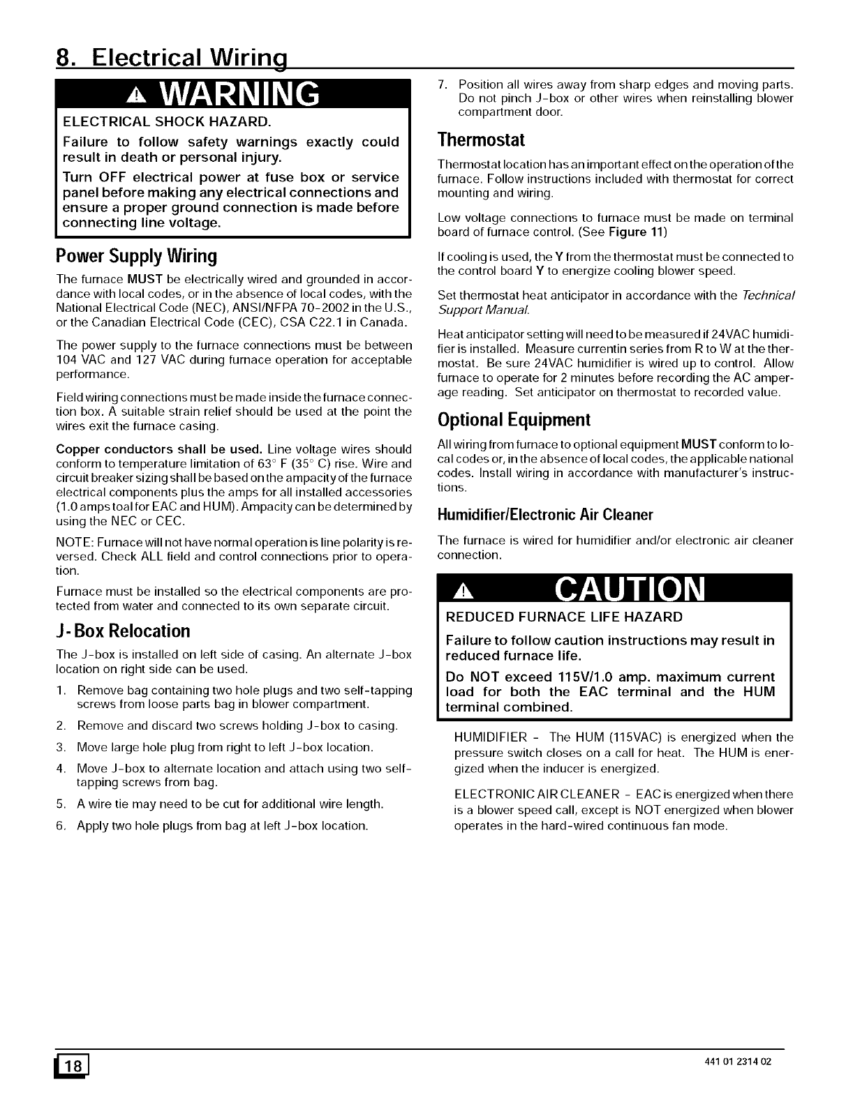
Power Supply Wiring
The furnace MUST be electrically wired and grounded in accor-
dance with local codes, or in the absence of local codes, with the
National Electrical Code (NEC), ANSI/NFPA 70-2002 in the U.S.,
or the Canadian Electrical Code (CEC), CSA C22.1 in Canada.
The power supply to the furnace connections must be between
104 VAC and 127 VAC during furnace operation for acceptable
performance.
Field wiring connections must be made inside the furnace connec-
tion box. A suitable strain relief should be used at the point the
wires exit the furnace casing.
Copper conductors shall be used. Line voltage wires should
conform to temperature limitation of 63 ° F (35 ° C) rise. Wire and
circuit breaker sizing shall be based on the ampacity of the furnace
electrical components plus the amps for all installed accessories
(1.0 amps toni for EAC and HUM). Ampacity can be determined by
using the NEC or CEC.
NOTE: Furnace will not have normal operation is line polarity is re-
versed. Check ALL field and control connections prior to opera-
tion.
If cooling is used, the Y from the thermostat must be connected to
the control board Y to energize cooling blower speed.
Set thermostat heat anticipator in accordance with the Technical
Support Manual.
Heat anticipator setting will need to be measured if 24VAC humidi-
fier is installed. Measure currentin series from R to W at thether-
mostat. Be sure 24VAC humidifier is wired up to control. Allow
furnace to operate for 2 minutes before recording the AC amper-
age reading. Set anticipator on thermostat to recorded value.
Optional Equipment
All wiring from furnace to optional equipment MUST conform to lo-
cal codes or, in the absence of local codes, the applicable national
codes. Install wiring in accordance with manufacturer's instruc-
tions.
Humidifier/Electronic Air Cleaner
The furnace is wired for humidifier and/or electronic air cleaner
connection.
Furnace must be installed so the electrical components are pro-
tected from water and connected to its own separate circuit.
J- Box Relocation
The J-box is installed on left side of casing. An alternate J-box
location on right side can be used.
1. Remove bag containing two hole plugs and two self-tapping
screws from loose parts bag in blower compartment.
2. Remove and discard two screws holding J-box to casing.
3. Move large hole plug from right to left J-box location.
4. Move J-box to alternate location and attach using two self-
tapping screws from bag.
5. A wire tie may need to be cut for additional wire length.
6. Apply two hole plugs from bag at left J-box location.
REDUCED FURNACE LIFEHAZARD
Failure to follow caution instructions may result in
reduced furnace life.
Do NOT exceed 115V/1.0 amp. maximum current
load for both the EAC terminal and the HUM
terminal combined.
HUMIDIFIER - The HUM (115VAC) is energized when the
pressure switch closes on a call for heat. The HUM is ener-
gized when the inducer is energized.
ELECTRONIC AIR CLEANER - EAC is energized when there
is a blower speed call, except is NOT energized when blower
operates in the hard-wired continuous fan mode.
_] 441 01 2314 02
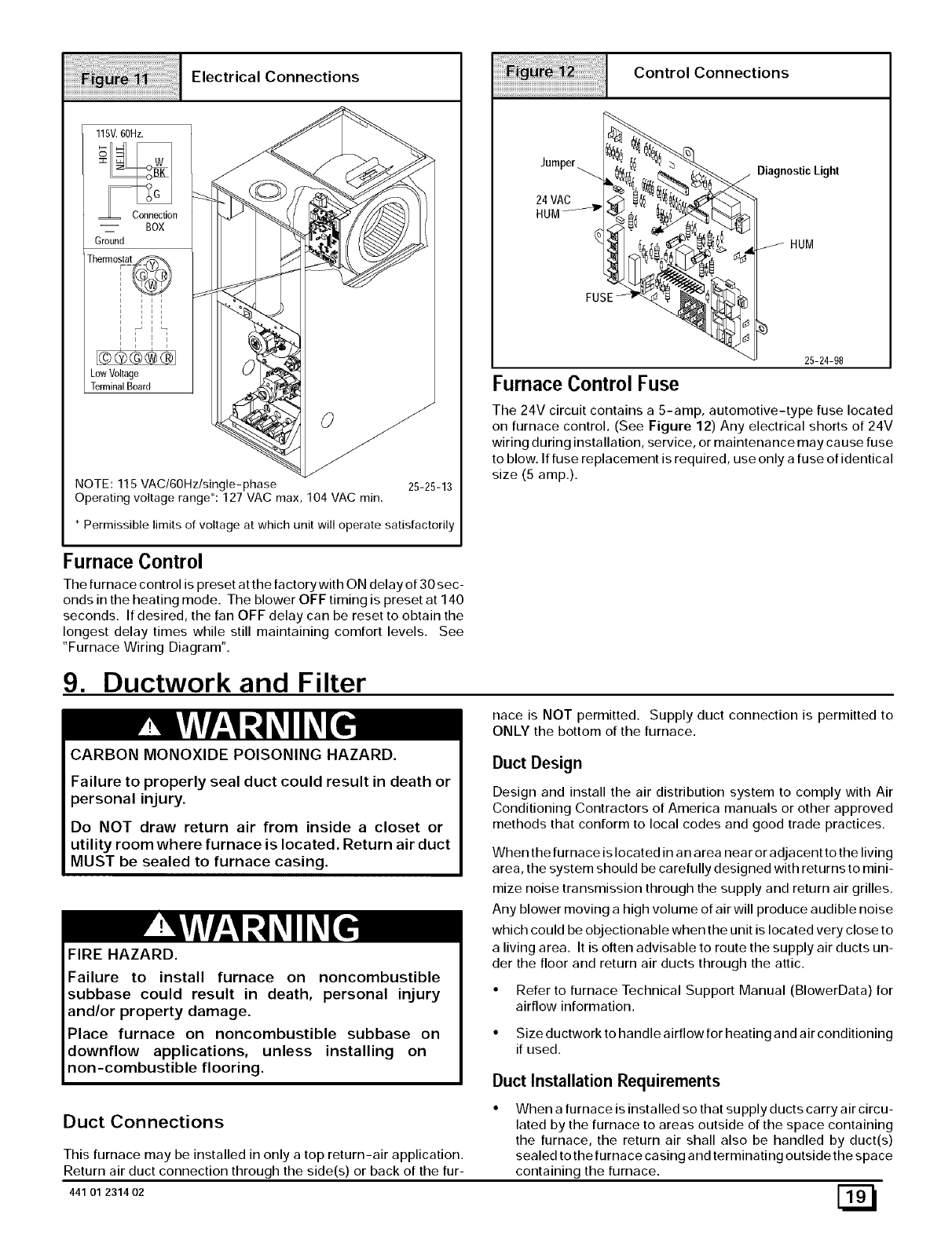
Electrical Connections
llSV. 60Hz.
-- BOX
Ground
Therm°_ i @
_tat
t i t i
i i i i
1 'I'
,I,I
Low Voltage
Terminal Board
O
NOTE: 115 VAC/6OHz/single-phase 25-25-13
Operating voltage range*: 127 VAC max, 104 VAC min.
* Permissible limits of voltage at which unit will operate satisfactorily
Control Connections
%
Jumperi
24 VAC
HUM_4 P
FUSE
DiagnosticLight
HUM
25-24-98
Furnace Control Fuse
The 24V circuit contains a 5-amp, automotive-type fuse located
on furnace control. (See Figure 12) Any electrical shorts of 24V
wiring during installation, service, or maintenance may cause fuse
to blow. If fuse replacement is required, use only a fuse of identical
size (5 amp.).
Furnace Control
The furnace control is preset at the factory with ON delay of 30 sec-
onds in the heating mode. The blower OFF timing is preset at 140
seconds. If desired, the fan OFF delay can be reset to obtain the
longest delay times while still maintaining comfort levels. See
"Furnace Wiring Diagram".
9. Ductwork and Filter
CARBON MONOXIDE POISONING HAZARD.
nace is NOT permitted. Supply duct connection is permitted to
ONLY the bottom of the furnace.
Failure to properly seal duct could result in death or
personal injury.
Do NOT draw return air from inside a closet or
utility room where furnace is located. Return air duct
MUST be sealed to furnace casing.
FIRE HAZARD.
Duct Design
Design and install the air distribution system to comply with Air
Conditioning Contractors of America manuals or other approved
methods that conform to local codes and good trade practices.
When the furnace is located in an area near or adjacent to the living
area, the system should be carefully designed with returns to mini-
mize noise transmission through the supply and return air grilles.
Any blower moving a high volume of air will produce audible noise
which could be objectionable when the unit is located very close to
a living area. It is often advisable to route the supply air ducts un-
der the floor and return air ducts through the attic.
Failure to install furnace on noncombustible
subbase could result in death, personal injury
and/or property damage.
Place furnace on noncombustible subbase on
downflow applications, unless installing on
Refer to furnace Technical Support Manual (BlowerData) for
airflow information.
Size ductwork to handle airflow for heating and air conditioning
if used.
non-combustible flooring. Duct Installation Requirements
Duct Connections
This furnace may be installed in only a top return-air application.
Return air duct connection through the side(s) or back of the fur-
441 01 231402
When a furnace is installed so that supply ducts carry air circu-
lated by the furnace to areas outside of the space containing
the furnace, the return air shall also be handled by duct(s)
sealed to the furnace casing and terminating outside the space
containing the furnace. Eil
CARBON MONOXIDE POISONING HAZARD.
Failure to follow safety warning exactly could
result in death or personal injury.
Install cooling coil on furnace discharge. Cool air
passing over heat exchanger could cause
condensate to form resulting in heat exchanger
failure.
When the furnace is used with a cooling unit, the furnace shall
be installed parallel with or on the upstream side of the cooling
unit to avoid condensation in the heating element.
With a parallel flow arrangement, the dampers or other means
used to control flow of air shall be adequate to prevent chilled
air from entering the furnace. Chilled air going through the fur-
nace could cause condensation and shorten furnace life.
Dampers (purchased locally) can be either automatic or manu-
al. Manually or automatically operated dampers MUST be
equipped with a means to prevent furnace or air conditioning
operation, unless damper is in the full heat or cool position
Installation of locking-type dampers is recommended in all
branches, or in individual ducts to balance system's air flows.
Non-combustible, flexible duct connectors are recommended
for return and supply connections to furnace.
If air return grille is located close to the fan inlet, install at least
one, 90 ° air turn between fan and inlet grille to reduce noise.
• Ductwork installed in attic, or exposed to outside temperatures
requires a minimum of 2" of insulation with outdoor type vapor
barrier.
• Ductwork installed in an indoor unconditioned space requires
a minimum of 1" of insulation with indoor type vapor barrier.
Inspection Panel on Some Models
For a furnace not equipped with a cooling coil, the outlet duct shall
be provided with a removable access panel. This opening shall be
accessible when the furnace is installed and shall be of such a size
that the heat excha nger can be viewed for possible openings using
light assistance or a probe can be inserted for sampling the air
stream. This access cover shall be attached in such a manner as
to prevent air leaks.
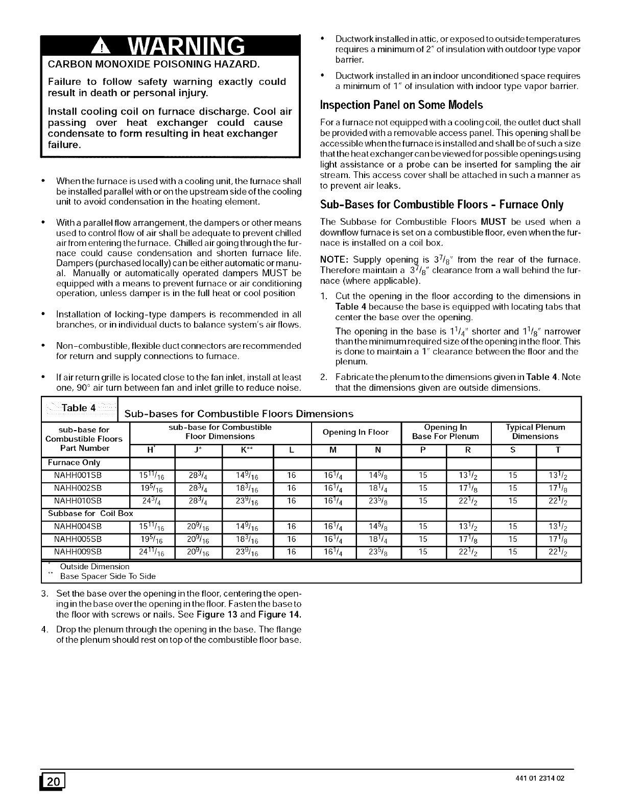
Sub-Bases for Combustible Floors -Furnace Only
The Subbase for Combustible Floors MUST be used when a
downflow furnace is set on a combustible floor, even when the fur-
nace is installed on a coil box.
NOTE: Supply opening is 37/8" from the rear of the furnace.
Therefore maintain a 37/8 ', clearance from a wall behind the fur-
nace (where applicable).
1. Cut the opening in the floor according to the dimensions in
Table 4 because the base is equipped with locating tabs that
center the base over the opening.
The opening in the base is 11/4" shorter and 11/8" narrower
than the minimum required size of the opening in the floor. This
is done to maintain a 1" clearance between the floor and the
plenum.
2. Fabricate the plenum to the dimensions given in Table 4. Note
that the dimensions given are outside dimensions.
Table 4Sub-bases for Combustible Floors Dimensions
N _
1511/16
195/16
24J/4
1511/16
195/16
24]]/16
sub-base for
Combustible Floors
Part Number
Furnace Only
NAHHOOISB
NAHHOO2SB
NAHHOIOSB
Subbase for Coil Box
NAHHOO4SB
NAHHOOSSB
NAHHOO9SB
Outside Dimension
_ Base Spacer Side To Side
3.
4,
sub-base for Combustible
Floor Dimensions
J* K**
283/4 149/16
283/4 183/16
28J/4 239/16
209/16 149/16
209/16 183/16
209/16 239/16
Opening In Floor
LM N
16 16114 14518
16 16114 18114
16 16]/4 235/8
16 161/4 145/8
16 161/4 181/4
16 16]/4 235/8
Opening In
Base For Plenum Typical Plenum
Dimensions
15
15
15
P R
15 131/2
15 171/8
15 221/2
15 131/2
15 171/8
15 221/2
15
15
15
131/2
171/8
221/2
131/2
171/8
221/2
Set the base over the opening in the floor, centering the open-
ing in the base over the opening in the floor. Fasten the base to
the floor with screws or nails. See Figure 13 and Figure 14.
Drop the plenum through the opening in the base. The flange
of the plenum should rest on top of the combustible floor base.
_] 441 01 2314 02
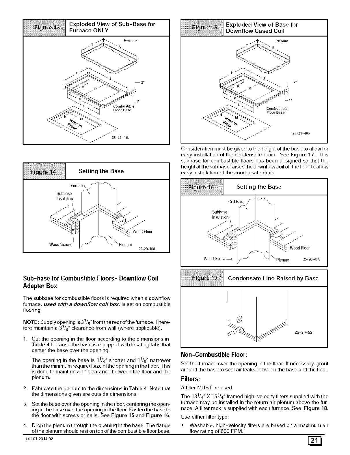
Exploded View of Sub-Base for
Furnace ONLY
Plenum
S
H
J
Combustible
Floor Base
25-21-46b
Setting the Base
Subbase
Insulation
Wood Floor
Plenum
25-20-46A
Exploded View of Base for
Downflow Cased Coil
Plenum
Combustible
Floor Base
25-21-46b
Consideration must be given to the height of the base to allow for
easy installation of the condensate drain. See Figure 17. This
subbase for combustible floors has been designed so that the
height of the subbase ra ises the downflow coil off the floor to allow
easy installation of the condensate drain
Setting the Base
co,
Subbase
Insulation /
Wood Screw _ _ _ Plenum 25-20-46A
Sub-base for Combustible Floors- Downflow Coil
Adapter Box
The subbase for combustible floors is required when a downflow
furnace, used with a downflowcoilbox, is set on combustible
flooring.
7
NOTE: Supply opening is 3 /8' from the rear of the furnace. There-
fore maintain a 37/8 " clearance from wall (where applicable).
1,
2,
3.
Cut the opening in the floor according to the dimensions in
Table 4 because the base is equipped with locating tabs that
center the base over the opening.
The opening in the base is 11/4" shorter and 11/8" narrower
than the minimum required size of the opening in the floor. This
is done to maintain a 1" clearance between the floor and the
plenum.
Fabricate the plenum to the dimensions in Table 4. Note that
the dimensions given are outside dimensions.
Set the base over the opening in the floor, centering the open-
ing in the base over the opening in the floor. Fasten the base to
the floor with screws or nails. See Figure 15 and Figure 16.
4.
441 01 231402
Drop the plenum through the opening in the base. The flange
of the plenum should rest on top of the combustible floor base.
Condensate Line Raised by Base
25-20-52
Non-Combustible Floor:
Set the furnace over the opening in the floor. If necessary, grout
around the base to seal air leaks between the base and the floor.
Filters:
A filter MUST be used.
The 181/4" X 1 53/4" framed high-velocity filters supplied with the
furnace may be installed in the return air plenum above the fur-
nace. A filter rack is supplied with each furnace. See Figure 18.
Use either filter type:
• Washable, high-velocity filters are based on a maximum air
flow rating of 600 FPM.
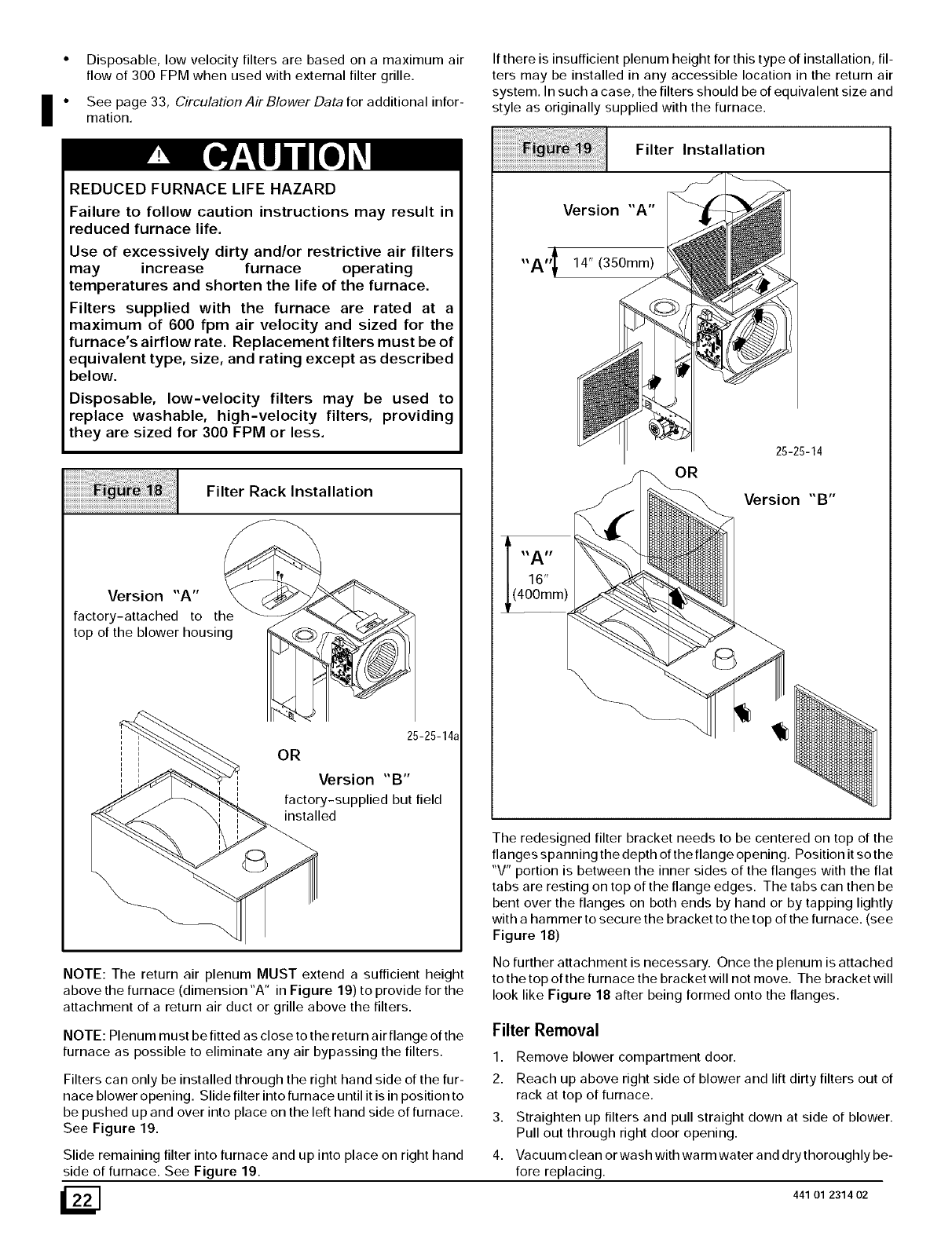
Disposable,lowvelocityfiltersarebasedonamaximumair
flowof300FPMwhenusedwithexternalfiltergrille.
i• See page 33, Circulation Air Blower Data for additional infor-
mation.
REDUCED FURNACE LIFE HAZARD
Failure to follow caution instructions may result in
reduced furnace life.
Use of excessively dirty and/or restrictive air filters
may increase furnace operating
temperatures and shorten the life of the furnace.
Filters supplied with the furnace are rated at a
maximum of 600 fpm air velocity and sized for the
furnace's airflow rate. Replacement filters must be of
equivalent type, size, and rating except as described
below.
Disposable, low-velocity filters may be used to
replace washable, high-velocity filters, providing
they are sized for 300 FPM or less.
Filter Rack Installation
Version "A"
factory-attached to the
top of the blower housing
25-25-14a
OR
Version "B"
factory-supplied but field
installed
NOTE: The return air plenum MUST extend a sufficient height
above the furnace (dimension "A" in Figure 19) to provide for the
attachment of a return air duct or grille above the filters.
NOTE: Plenum must be fitted as close to the return air flange of the
furnace as possible to eliminate any air bypassing the filters.
Filters can only be installed through the right hand side of the fur-
nace blower opening. Slide filter into furnace until it is in position to
be pushed up and over into place on the left hand side of furnace.
See Figure 19.
Slide remaining filter into furnace and up into place on right hand
side of furnace. See Figure 19.
If there is insufficient plenum height for this type of installation, fil-
ters may be installed in any accessible location in the return air
system. In such a case, the filters should be of equivalent size and
style as originally supplied with the furnace.
Filter Installation
Version "A'"
,,A,, l 14" (350mm)
25-25-14
OR
Version "B"
16"
(400mm)
The redesigned filter bracket needs to be centered on top of the
flanges spanning the depth of the flange opening. Position it sothe
"V" portion is between the inner sides of the flanges with the flat
tabs are resting on top of the flange edges. The tabs can then be
bent over the flanges on both ends by hand or by tapping lightly
with a hammer to secure the bracket to the top of the furnace. (see
Figure 18)
No further attachment is necessary. Once the plenum is attached
to the top of the furnace the bracket will not move. The bracket will
look like Figure 18 after being formed onto the flanges.
Filter Removal
1. Remove blower compartment door.
2. Reach up above right side of blower and lift dirty filters out of
rack at top of furnace.
3. Straighten up filters and pull straight down at side of blower.
Pull out through right door opening.
4. Vacuum clean or wash with warm water and dry thoroughly be-
fore replacing.
_] 441 O1 2314 02
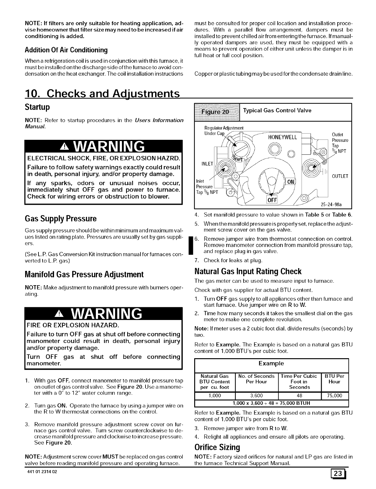
NOTE: If filters are only suitable for heating application, ad-
vise homeowner that filter size may need to be increased if air
conditioning is added.
Addition Of Air Conditioning
When a refrigeration coil is used in conjunction with this furnace, it
must be installed on the discharge side of the furnace to avoid con-
densation on the heat exchanger. The coil installation instructions
must be consulted for proper coil location and installation proce-
dures. With a parallel flow arrangement, dampers must be
installed to prevent chilled air from entering the furnace. If ma nual-
ly operated dampers are used, they must be equipped with a
means to prevent operation of either unit unless the damper is in
full heat or full cool position.
Copper or plastic tubing may be used for the condensate drain line.
10. Checks and AdJustments
Startup
NOTE: Refer to startup procedures in the Users Information
Manual.
ELECTRICAL SHOCK, FIRE, OR EXPLOSION HAZRD.
Failure to follow safety warnings exactly could result
in death, personal injury, and/or property damage.
If any sparks, odors or unusual noises occur,
immediately shut OFF gas and power to furnace.
Check for wiring errors or obstruction to blower.
iiiiiiiil!!!!! ii¸I¸iiiiii_¸I¸ !!i!!iiil;;i;;iiiiiiiiiiiiiiii;iiiiiii
Typical Gas Control Valve
RegulatorAdjustment
UnderCa
Inlet
Pressure
Tap1/8NPT
HONEYWELL
©o
Outlet
Pressure
Tap
1/8NPT
/
OUTLET
25-24-98a
Gas SupplyPressure
Gas supply pressure should be within minimum and maximum val-
ues listed on rating plate. Pressures are usually set by gas suppli-
ers.
(See L.P. Gas Conversion Kit instruction manual for furnaces con-
verted to L.P. gas)
Manifold Gas Pressure Adjustment
NOTE: Make adjustment to manifold pressure with burners oper-
ating.
FIRE OR EXPLOSION HAZARD.
Failure to turn OFF gas at shut off before connecting
manometer could result in death, personal injury
and/or property damage.
Turn OFF gas at shut off before connecting
manometer.
1. With gas OFF, connect manometer to manifold pressure tap
on outlet of gas control valve. See Figure 20. Use a manome-
ter with a 0" to 12" water column range.
2.
3.
Turn gas ON. Operate the furnace by using a jumper wire on
the R to W thermostat connections on the control.
Remove manifold pressure adjustment screw cover on fur-
nace gas control valve. Turn screw counterclockwise to de-
crease manifold pressure and clockwise to increase pressure.
See Figure 20.
NOTE: Adjustment screw cover MUST be replaced on gas control
valve before reading manifold pressure and operating furnace.
441 01 231402
4. Set manifold pressure to value shown in Table 5 or Table 6.
5. When the manifold pressure is properly set, replace the adjust-
ment screw cover on the gas valve.
Remove jumper wire from thermostat connection on control.
Remove manometer connection from manifold pressure tap,
and replace plug in gas valve.
7. Check for leaks at plug.
Natural Gas Input Rating Check
The gas meter can be used to measure input to furnace.
Check with gas supplier for actual BTU content.
1. Turn OFF gas supply to all appliances other than furnace and
start furnace. Use jumper wire on R to W.
2. Time how many seconds it takes the smallest dial on the gas
meter to make one complete revolution.
Note: If meter uses a 2 cubic foot dial, divide results (seconds) by
two.
Refer to Example. The Example is based on a natural gas BTU
content of 1,000 BTU's per cubic foot.
Example
6.
Natural Gas No. of Seconds Time Per Cubic BTU Per
BTU Content Per Hour Foot in Hour
per cu, foot Seconds
1,000 3,600 48 75,000
1,000 x 3,600 + 48 = 75,000 BTUH
Refer to Example. The Example is based on a natural gas BTU
content of 1,000 BTU's per cubic foot.
3. Remove jumper wire from R to W.
4. Relight all appliances and ensure all pilots are operating.
Orifice Sizing
NOTE: Factory sized orifices for natural and LP gas are listed in
the furnace Technical Support Manual.
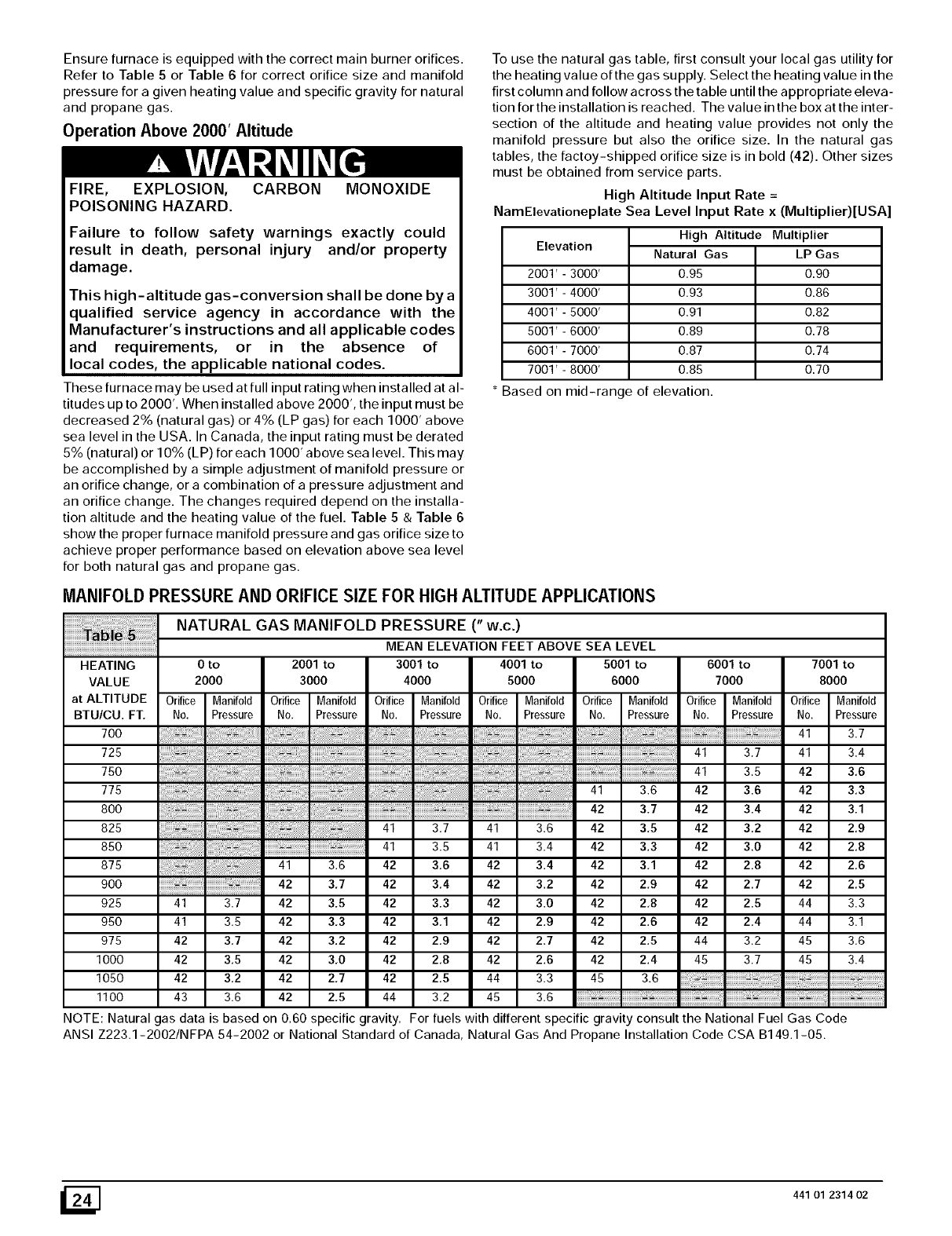
Ensurefurnaceisequippedwiththe correct main burner orifices.
Refer to Table 5 or Table 6 for correct orifice size and manifold
pressure for a given heating value and specific gravity for natural
and propane gas.
Operation Above 2000' Altitude
FIRE, EXPLOSION, CARBON MONOXIDE
POISONING HAZARD.
Failure to follow safety warnings exactly could
result in death, personal injury and/or property
damage.
This high-altitude gas-conversion shall be done by a
qualified service agency in accordance with the
Manufacturer's instructions and all applicable codes
and requirements, or in the absence of
local codes, the applicable national codes.
These furnace may be used at full input rating when installed at al-
titudes up to 2000'. When installed above 2000', the input must be
decreased 2% (natural gas) or 4% (LP gas) for each 1000' above
sea level in the USA. In Canada, the input rating must be derated
o
5% (natural) or 10 _ (LP) for each 1000' above sea level. This may
be accomplished by a simple adjustment of manifold pressure or
an orifice change, or a combination of a pressure adjustment and
an orifice change. The changes required depend on the installa-
tion altitude and the heating value of the fuel. Table 5 &Table 6
show the proper furnace manifold pressure and gas orifice size to
achieve proper performance based on elevation above sea level
for both natural gas and propane gas.
To use the natural gas table, first consult your local gas utility for
the heating value of the gas supply. Select the heating value in the
first column and follow across the table until the appropriate eleva-
tion for the installation is reached. The value in the box at the inter-
section of the altitude and heating value provides not only the
manifold pressure but also the orifice size. In the natural gas
tables, the factoy-shipped orifice size is in bold (42). Other sizes
must be obtained from service parts.
High Altitude Input Rate =
NamElevationeplate Sea Level Input Rate x (Multiplier)[USA]
Elevation
2001'-3000'
3001'-4000'
4001'-5000'
5001'-6000'
6001'-7000'
7001'-8000'
High Altitude Multiplier
Natural Gas
0.95
0.93
0.91
0.89
0.87
0.85
LP Gas
0.90
0.86
0.82
0.78
0.74
0.70
* Based on mid-range of elevation.
MANIFOLD PRESSUREAND ORIFICE SIZE FOR HIGH ALTITUDEAPPLICATIONS
HEATING
VALUE
at ALTITUDE
BTU/CU. FT.
7OO
725
75O
775
8OO
825
85O
875
9OO
925
95O
975
1000
1050
1100
NATURAL GAS MANIFOLD PRESSURE (" w.c.)
MEAN ELEVATION FEET ABOVE SEA LEVEL
0 to 2001 to 3001 to 4001 to 5001 to
2000 3000 4000 5000 6000
Orifice Manifold Orifice Manifold Orifice Manifold Orifice Manifold Orifice Manifold
No. Pressure No. Pressure No. Pressure No. Pressure No. Pressure
6001 to 7001 to
7000 8000
Orifice Manifold Orifice Manifold
No. Pressure No. Pressure
41 3.7
41 3.7 41 3.4
41 3.5 42 3,6
41 3.6 42 3.6 42 3,3
42 3.7 42 3.4 42 3.1
3.6 42 3,5 42 3.2 42 2,9
3.4 42 3.3 42 3.0 42 2.8
3.4 42 3.1 42 2.8 42 2.6
3.2 42 2,9 42 2.7 42 2,5
3.0 42 2,8 42 2.5 44 3.3
2.9 42 2.6 42 2.4 44 3.1
2.7 42 2.5 44 3.2 45 3.6
2.6 42 2.4 45 3.7 45 3.4
3.3 45 3.6
41 3.7 41
41 3.5 41
41 3.6 42 3.6 42
42 3,7 42 3,4 42
41 3.7 42 3.5 42 3.3 42
41 3.5 42 3,3 42 3,1 42
42 3.7 42 3.2 42 2.9 42
42 3,5 42 3,0 42 2.8 42
42 3,2 42 2,7 42 2,5 44
43 3.6 42 2.5 44 3.2 45 3.6
NOTE: Natural gas data is based on 0.60 specific gravity. For fuels with different specific gravity consult the National Fuel Gas Code
ANSI Z223.1-2002/NFPA 54-2002 or National Standard of Canada, Natural Gas And Propane Installation Code CSA B149.1-05.
_] 441 01 2314 02
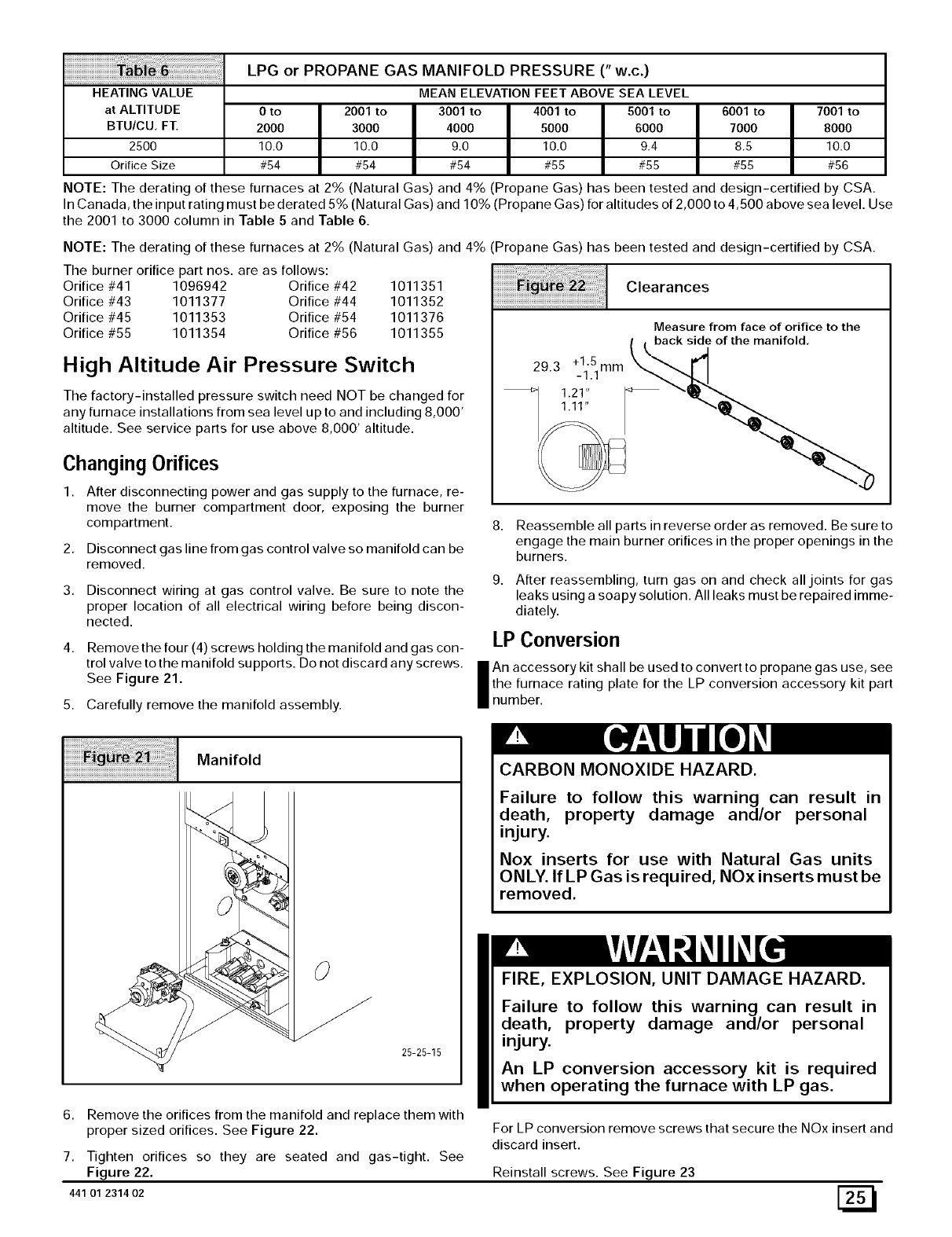
HEATING VALUE
at ALTITUDE
BTU/CU, FT.
2500
Orifice Size
LPG or PROPANE GAS MANIFOLD PRESSURE (" w.c.)
MEAN ELEVATION FEET ABOVE SEA LEVEL
0to 2001 to 3001 to 4001 to 5001 to
2000 3000 4000 5000 6000
10.0 10.0 9.0 10.0 9.4
#54 #54 #54 #55 #55
6001 to 7001 to
7000 8000
8.5 10.0
#55 #56
NOTE: The derating of these furnaces at 2% (Natural Gas) and 4% (Propane Gas) has been tested and design-certified by CSA.
In Canada, the input rating must be derated 5% (Natural Gas) and 10% (Propane Gas) for altitudes of 2,000 to 4,500 above sea level. Use
the 2001 to 3000 column in Table 5 and Table 6.
NOTE: The derating of these furnaces at 2% (Natural Gas) and 4% (Propane Gas) has been tested and design-certified by CSA.
The burner orifice part nos. are as follows:
Orifice #41 1096942 Orifice #42 1011351
Orifice #43 1011377 Orifice #44 1011352
Orifice #45 1011353 Orifice #54 1011376
Orifice #55 1011354 Orifice #56 1011355
High Altitude Air Pressure Switch
The factory-installed pressure switch need NOT be changed for
any furnace installations from sea level up to and including 8,000'
altitude. See service parts for use above 8,000' altitude.
Changing Orifices
1. After disconnecting power and gas supply to the furnace, re-
move the burner compartment door, exposing the burner
compartment.
2. Disconnect gas line from gas control valve so manifold can be
removed.
3. Disconnect wiring at gas control valve. Be sure to note the
proper location of all electrical wiring before being discon-
nected.
4. Remove the four (4) screws holding the manifold and gas con-
trol valve to the manifold supports. Do not discard any screws.
See Figure 21.
5. Carefully remove the manifold assembly.
Clearances
Measure from face of orifice to the
( I back side of the manifold,
8. Reassemble all parts in reverse order as removed. Be sure to
engage the main burner orifices in the proper openings in the
burners.
9. After reassembling, turn gas on and check all joints for gas
leaks using a soapy solution. All leaks must be repaired imme-
diately.
LP Conversion
An accessory kit shall be used to convert to propane gas use, see
the furnace rating plate for the LP conversion accessory kit part
number.
6.
7.
441 01 231402
Manifold
O
25-25-15
Remove the orifices from the manifold and replace them with
proper sized orifices. See Figure 22.
Tighten orifices so they are seated and gas-tight. See
Figure 22.
CARBON MONOXIDE HAZARD.
Failure to follow this warning can result in
death, property damage and/or personal
injury.
Nox inserts for use with Natural Gas units
ONLY. If LP Gas is required, NOx inserts must be
removed.
FIRE, EXPLOSION, UNIT DAMAGE HAZARD.
Failure to follow this warning can result in
death, property damage and/or personal
injury.
An LP conversion accessory kit is required
when operating the furnace with LP gas.
For LP conversion remove screws that secure the NOx insert and
discard insert.
Reinstall screws. See Figure 23
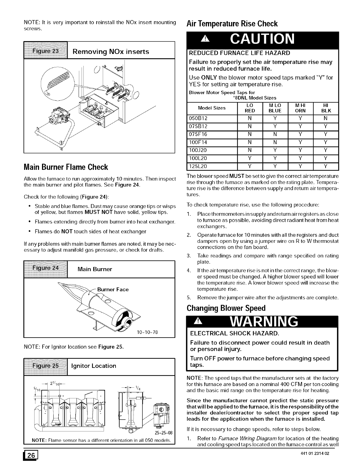
NOTE: It is very important to reinstall the NOx insert mounting Air Temperature Rise Check
screws.
iiiiiiiiiiiiiiiiiiiiiiiiiiiii_i_i!:!!!!i_!ill¸II¸II¸I¸;i;_i!i_i_i_i_ii!i!i!!!!!!i!_;_;_;_;_;_;_;_;_;_i_i!iiiiiiiiiiiiiii_iii!!_iiiiiiiii_i;;i_i_i!i!_!;;!iiiiii!_
Removing NOx inserts
Main Burner Flame Check
Allow the furnace to run approximately 10 minutes. Then inspect
the main burner and pilot flames. See Figure 24.
Check for the following (Figure 24):
• Stable and blue flames. Dust may cause orange tips or wisps
of yellow, but flames MUST NOT have solid, yellow tips.
• Flames extending directly from burner into heat exchanger.
• Flames do NOT touch sides of heat exchanger
If any problems with main burner flames are noted, it may be nec-
essary to adjust manifold gas pressure, or check for drafts.
Main Burner
NOTE: For Ignitor location see Figure 25.
Ignitor Location
21/16
25-25-08
NOTE: Flame sensor has a different orientation in all 050 models.
REDUCED FURNACE LIFE HAZARD
Failure to properly set the air temperature rise may
result in reduced furnace life.
Use ONLY the blower motor speed taps marked "Y" for
YES for setting air temperature rise.
Blower Motor Speed Taps for
M HI HI
ModelSizes ORN BLK
050B12 Y N
075B12 Y Y
075F16 Y Y
100F14 Y Y
100J20 Y Y
100L20 Y Y
125L20 Y Y
"8DNL ModelSizes
LO M LO
RED BLUE
N Y
N Y
N N
N N
N Y
Y Y
Y Y
The blower speed MUST be set to give the correct air temperature
rise through the furnace as marked on the rating plate. Tempera-
ture rise is the difference between supply and return air tempera-
tures.
To check temperature rise, use the following procedure:
1. Place thermometers in supply and return air registers as close
to furnace as possible, avoiding direct radiant heat from heat
exchangers.
2. Operate furnace for 10 minutes with all the registers and duct
dampers open by using a jumper wire on R to W thermostat
connections on the fan board.
3. Take readings and compare with range specified on rating
plate.
4. If the air temperature rise is not in the correct range, the blow-
er speed must be changed. A higher blower speed will lower
the temperature rise. A lower blower speed will increase the
temperature rise.
5. Remove the jumper wire after the adjustments are complete.
Changing Blower Speed
ELECTRICAL SHOCK HAZARD.
Failure to disconnect power could result in death
or personal injury.
Turn OFF power to furnace before changing speed
taps.
NOTE: The speed taps that the manufacturer sets at the factory
for this furnace are based on a nominal 400 CFM per ton cooling
and the basic mid range on the temperature rise for heating.
Since the manufacturer cannot predict the static pressure
that will be applied to the furnace, it is the responsibility of the
installer dealer/contractor to select the proper speed tap
leads for the application when the furnace is installed.
If it is necessary to change speeds, refer to steps below.
1. Refer to Furnace Hhking Diagram for location of the heating
and cooling speed taps located on the furnace control as well
441 01 2314 02
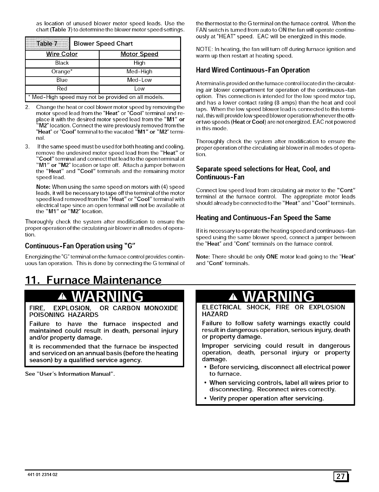
aslocationof unusedblowermotorspeedleads.Usethe
chart (Table 7) to determine the blower motor speed settin( s.
Blower Speed Chart
Wire Color
Black
Orange*
Blue
Red
Motor Speed
High
Med-High
Med- Low
Low
*Med-High speed may not be provided on all models.
2, Change the heat or cool blower motor speed by removing the
motor speed lead from the "Heat" or "Cool" terminal and re-
place it with the desired motor speed lead from the "MI" or
"M2" location. Connect the wire previously removed from the
"Heat" or "Cool" terminal to the vacated "M1" or "M2" termi-
nal.
3, If the same speed must be used for both heating and cooling,
remove the undesired motor speed lead from the "Heat" or
"Cool" terminal and connect that lead to the open terminal at
"M1" or "M2" location or tape off. Attach a jumper between
the "Heat" and "Cool" terminals and the remaining motor
speed lead.
Note: When using the same speed on motors with (4) speed
leads, it will be necessary to tape off the terminal of the motor
speed lead removed from the "Heat" or "Cool" terminal with
electrical tape since an open terminal will not be available at
the "MI" or "M2" location.
Thoroughly check the system after modification to ensure the
proper operation of the circulating air blower in all modes of opera-
tion.
Continuous-Fan Operation using "G"
Energizing the"G" terminal on the furnace control provides contin-
uous fan operation. This is done by connecting the G terminal of
11. Furnace Maintenance
the thermostat to the G terminal on the furnace control. When the
FAN switch is turned from auto to ON the fan will operate continu-
ously at "HEAT" speed. EAC will be energized in this mode.
NOTE: In heating, the fan will turn off during furnace ignition and
warm up then restart at heating speed.
Hard Wired Continuous-Fan Operation
A terminal is provided on the furnace control located in the circulat-
ing air blower compartment for operation of the continuous-fan
option. This connection is intended for the low speed motor tap,
and has a lower contact rating (8 amps) than the heat and cool
taps. When the low speed blower lead is connected to this termi-
nal, this will provide low speed blower operation whenever the oth-
er two speeds (Heat or Cool) are not energized. EAC not powered
in this mode.
Thoroughly check the system after modification to ensure the
proper operation of the circulating air blower in all modes of opera-
tion.
Separate speed selections for Heat, Cool, and
Continuous-Fan
Connect low speed lead from circulating air motor to the "Cont"
terminal at the furnace control. The appropriate motor leads
should already be connected to the "Heat" and "Cool" terminals.
Heating and Continuous-Fan Speed the Same
If it is necessary to operate the heating speed and continuous -fan
speed using the same blower speed, connect a jumper between
the "Heat" and "Cont" terminals on the furnace control.
Note: There should be only ONE motor lead going to the "Heat"
and "Cont" terminals.
FIRE, EXPLOSION, OR CARBON MONOXIDE
POISONING HAZARDS
Failure to have the furnace inspected and
maintained could result in death, personal injury
and/or property damage.
It is recommended that the furnace be inspected
and serviced on an annual basis (before the heating
season) by a qualified service agency.
See "User's Information Manual".
ELECTRICAL SHOCK, FIRE OR EXPLOSION
HAZARD
Failure to follow safety warnings exactly could
result in dangerous operation, serious injury, death
or property damage.
Improper servicing could result in dangerous
operation, death, personal injury or property
damage.
• Before servicing, disconnect all electrical power
to furnace.
• When servicing controls, label all wires prior to
disconnecting. Reconnect wires correctly.
• Verify proper operation after servicing.
441 01 2314 02 [_
12. Sequence of Operation & Diagnostics
The following is the normal operating sequence.
Cooling (Y) Request:
24VAC signals applied to Y & G terminals of FCB (furnace control board)
• Cool motor speed is energized after 5 second Cool Fan On Delay time.
Y & G signals removed from FCB
• Cool motor speed is de-energized after 90 second Cool Fan Off Delay time.
Continuous Circulating Fan (G) Request:
24 VAC signal is applied to G terminal of the FCB.
• Heat motor speed is energized without delay.
G signal removed from FCB.
• Heat motor speed is de-energized after 5 second delay.
NOTE 1) Furnace de-energizes the fan during the heat exchanger warm-up period on a call for Heating that occurs during a G request
unless a blower motor lead is connected to the Cont terminal on the FCB, in which case see NOTE 2).
NOTE 2) Heating or Cooling requests received during a Fan request cause the fan speed to change to the appropriate heat or cool
speed after the Fan on Delay time expires. The fan returns to continuous circulating speed after the selected Fan Off Delay time ex pires
following loss of the Heating or Cooling request.
Continuous Circulating Fan Hard-Wired (Cont) Request:
Field selected low speed motor tap installed on "CONT" terminal.
• Low speed is energized when power applied to furnace. Operates at this speed continuously while there are no other
blower demands from furnace control. Fan demands from furnace control for heat, cool or "G" will override hard-wired speed tap.
NOTE 3) EAC is NOT active for hard-wired mode but IS active for fan demands from furnace control for heat, cool and "G".
Heating (W) Request:
Heating (W) Request:
• 24 VAC signal applied to W terminal of FCB.
• Inducer motor turns on and the pressure switch(es) close(s).
• Following a 15 second prepurge delay after the pressure switches closes, the igniter begins a 17 second warm-up.
• The gas valve is energized, the main burners light and flame is sensed.
• The igniter is de-energized after the main burners ignite.
• FCB will delay blower operation for the 30 seconds timed from the opening of the gas valve.
W signal removed from FCB.
• The gas valve de-energizes and the main burners go out.
• The inducer runs for a 15 second postpurge period.
• The fan stays at Heat speed.
• The fan de-energizes after the selected Heat Fan Off Delay time expires, timed from the gas valve de-energizing.
HUMIDI FIE R - The 24V HUM is energized when the pressure switch closes on a call for heat. The 115V HUM (called HUM on Control)
is energized when the inducer is energized.
ELECTRONIC AIR CLEAN E R - EAC is energized when there is a blower speed call. It is NOT energized when blower operates in the
hard-wired continuous fan mode.
NOTE 4) If a new Heating request arrives while the control is waiting in the Heat Fan Off Delay time, the FCB will wait for the selected
Heat Fan Off Delay then start a new heating cycle as long as the heat call remains.
_] 441 01 2314 02
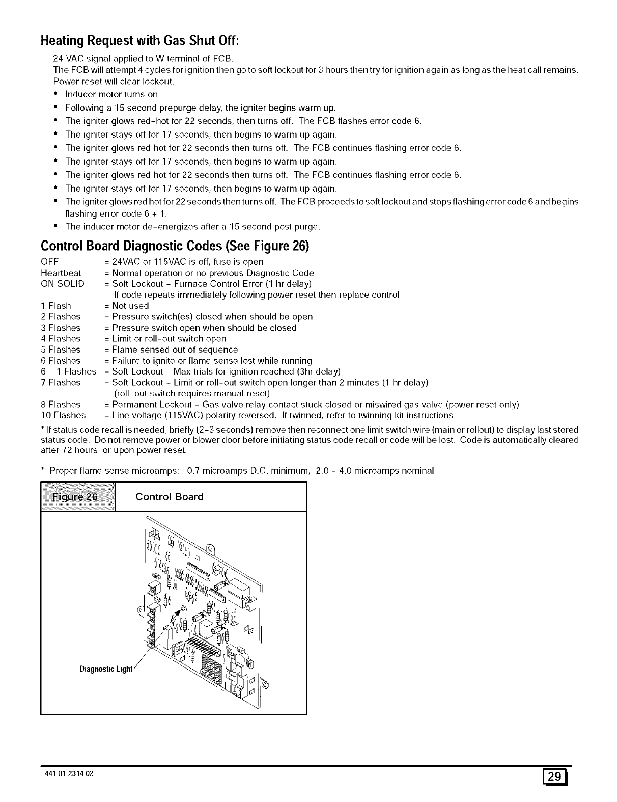
Heating Request with Gas Shut Off:
24 VAC signal applied to W terminal of FCB.
The FCB will attempt 4 cycles for ignition then go to soft lockout for 3 hours then try for ignition again as long as the heat call remains.
Power reset will clear lockout.
• Inducer motor turns on
• Following a 15 second prepurge delay, the igniter begins warm up.
• The igniter glows red-hot for 22 seconds, then turns off. The FCB flashes error code 6.
• The igniter stays off for 17 seconds, then begins to warm up again.
• The igniter glows red hot for 22 seconds then turns off. The FCB continues flashing error code 6.
• The igniter stays off for 17 seconds, then begins to warm up again.
• The igniter glows red hot for 22 seconds then turns off. The FCB continues flashing error code 6.
• The igniter stays off for 17 seconds, then begins to warm up again.
• The igniter glows red hot for 22 seconds then turns off. The FCB proceeds to soft lockout and stops flashing error code 6 and begins
flashing error code 6 + 1.
• The inducer motor de-energizes after a 15 second post purge.
Control Board Diagnostic Codes (See Figure 26)
OFF = 24VAC or 115VAC is off, fuse is open
Heartbeat = Normal operation or no previous Diagnostic Code
ON SOLID = Soft Lockout - Furnace Control Error (1 hr delay)
If code repeats immediately following power reset then replace control
1 Flash = Not used
2 Flashes = Pressure switch(es) closed when should be open
3 Flashes = Pressure switch open when should be closed
4 Flashes = Limit or roll-out switch open
5 Flashes = Flame sensed out of sequence
6 Flashes = Failure to ignite or flame sense lost while running
6 + 1 Flashes = Soft Lockout - Max trials for ignition reached (3hr delay)
7 Flashes = Soft Lockout - Limit or roll-out switch open longer than 2 minutes (1 hr delay)
(roll-out switch requires manual reset)
8 Flashes = Permanent Lockout - Gas valve relay contact stuck closed or miswired gas valve (power reset only)
10 Flashes = Line voltage (115VAC) polarity reversed. If twinned, refer to twinning kit instructions
* If status code recall is needed, briefly (2-3 seconds) remove then reconnect one limit switch wire (main or rollout) to display last stored
status code. Do not remove power or blower door before initiating status code recall or code will be lost. Code is automatically cleared
after 72 hours or upon power reset.
* Proper flame sense microamps: 0.7 microamps D.C. minimum 2.0 - 4.0 microamps nominal
Control Board
441 01 2314 02 [_

_] 44101231402
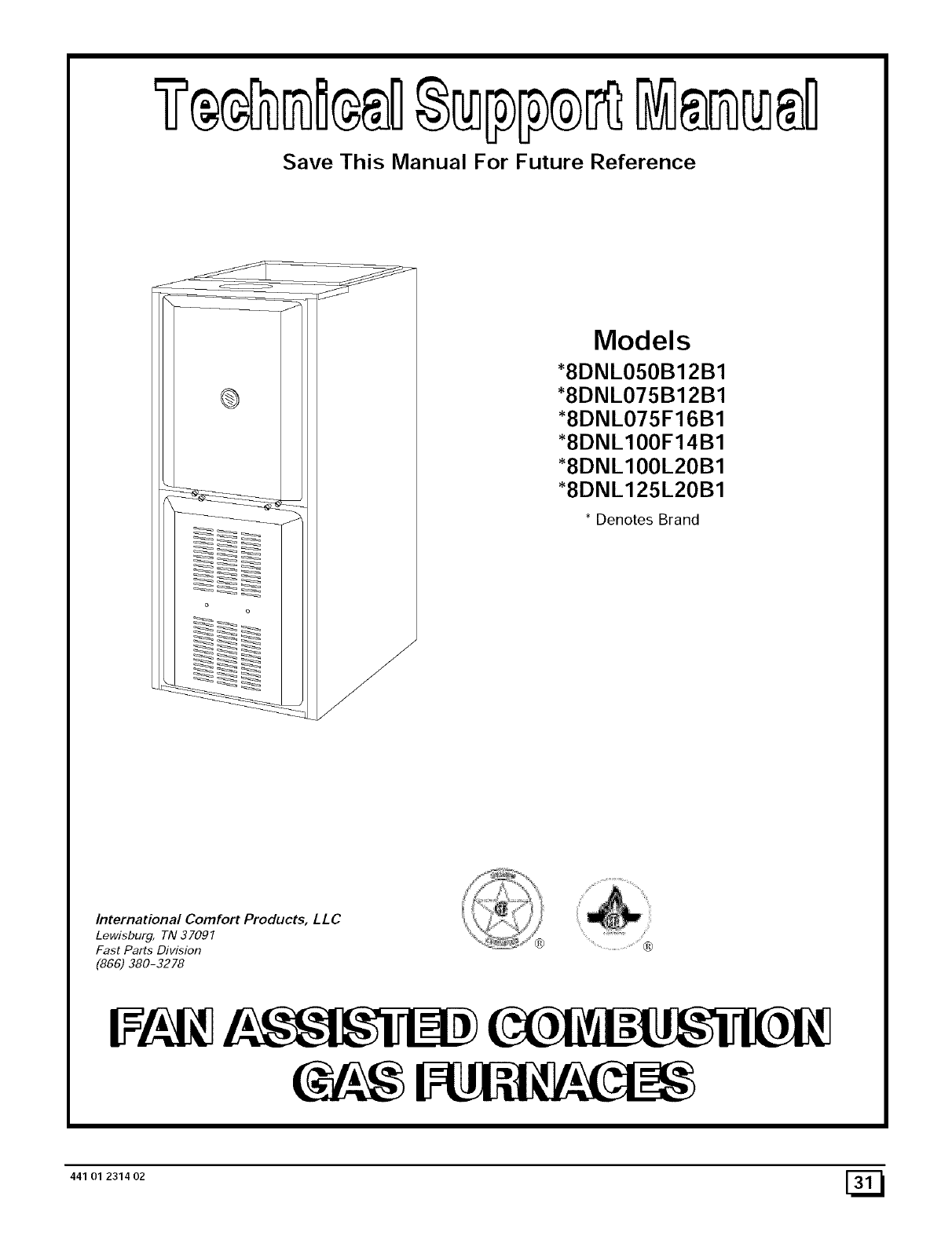
Save This Manual For Future Reference
Models
+8DNL050B12B1
+8DNL075B12B1
+8DNL075F16B1
+8DNL100F14B1
+8DNL100L20B1
+8DNL125L20B1
+ Denotes Brand
International Comfort Products, LLC
Lewisburg, TN 37097
Fast Parts Division
(866) 380-3278
/
441 01 2314 02 [_
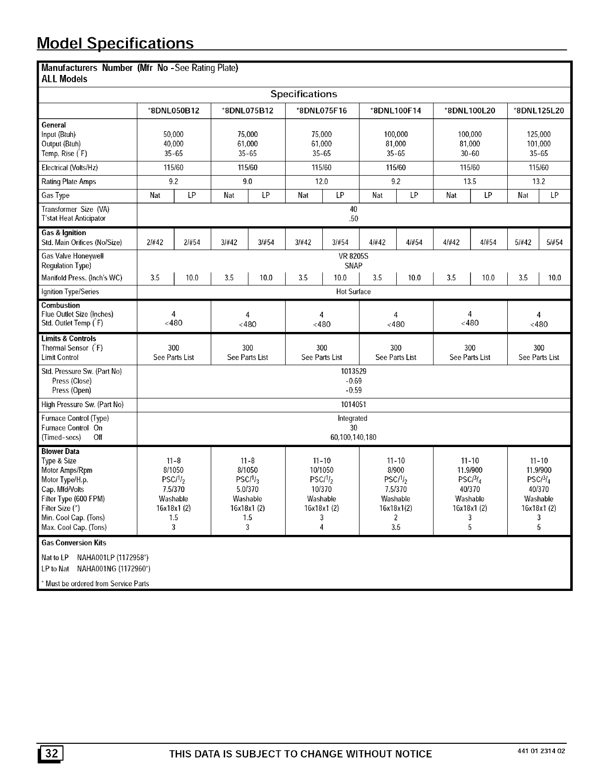
Model Specifications
Manufacturers Number (Mfr No-See RatingPlate)
ALL Models
Specifications
*8DNLO5OB12 *8DNLO75B12 *8DNLO75F16 *8DNLIOOF14 *8DNLIOOL20 *8DNL125L20
General
Input(8tuh) 50,000 75,000 75,000 100,000 100,000 125,000
Output(Btuh) 40,000 61,000 61,000 81,000 81,000 101,000
Temp. Rise (F) 35-65 35-65 35-65 35-65 30-60 35-65
Electrical(Volts/Hz) 115/60 115/60 115/60 115/60 115/60 115/60
RatingPlateAmps 9.2 9.0 12.0 9.2 13.5 13.2
GasType NatI,P NatI LP NatI'P NatI'P Nat Nat
Transformer Size (VA) 40
T'stat Heat Anticipator .50
Gas & Ignition
Std.MainOrifices(No/Size) 2I#42 2t#54 3I#42 3/#54 3/#42 3/#54 4/#42 4/#54 4/#42 4/#54 5/#42 5/#54
GasValve Honeywell VR 8205S
RegulationType) SNAP
ManifoldPress.(Inch'sWC) 3.5 110.0 3.5 110.0 3.5 110.0 3.5 110.0 3.5 110.0 3.5 110.0
IgnitionTypelSeries Hot Surface
Combustion
FlueOutlet Size (Inches) 4 4 4 4 4 4
Std.OutletTemp(F) <480 <480 <480 <480 <480 <480
Limits & Controls
Thermal Sensor (F) 300 300 300 300 300 300
LimitControl See PartsList See PartsList See PartsList See PartsList See PartsList See PartsList
Std.PressureSw. (PartNo) 1013529
Press (Close) -0.69
Press (Open) -0.59
HighPressureSw. (PartNo) 1014051
FurnaceControl(Type) Integrated
FurnaceControl On 30
(Timed-secs) Off 60,100,140,180
Blower Data
Type & Size 11-8 11-8 11-10 11-10 11-10 11-10
MotorAmps/Rpm 8/1050 811050 10/1050 8/900 11.91900 11.91900
MotorTypelH.p. PSC/II2 PSC/II3 PSC/I/2 PSC/II2 PSC/314 PSC/3/4
Cap.Mfd/Volts 7.51370 5.01370 10/370 7.51370 40/370 40/370
FilterType(600FPM) Washable Washable Washable Washable Washable Washable
FilterSize (") 16x18xl (2) 16x18xl (2) 16x18x1(2) 16x18xl(2) 16x18xl (2) 16x18x1(2)
Min.CoolCap. (Tons) 1.5 1.5 3 2 3 3
Max.CoolCap. (Tons) 3 3 4 3.5 5 5
Gas Conversion Kits
Natto LP NAHA001LP(1172958*)
LPtoNat NAHA001NG(1172960*)
* Must be orderedfrom ServiceParts
THIS DATA IS SUBJECT TO CHANGE WITHOUT NOTICE 44101231402
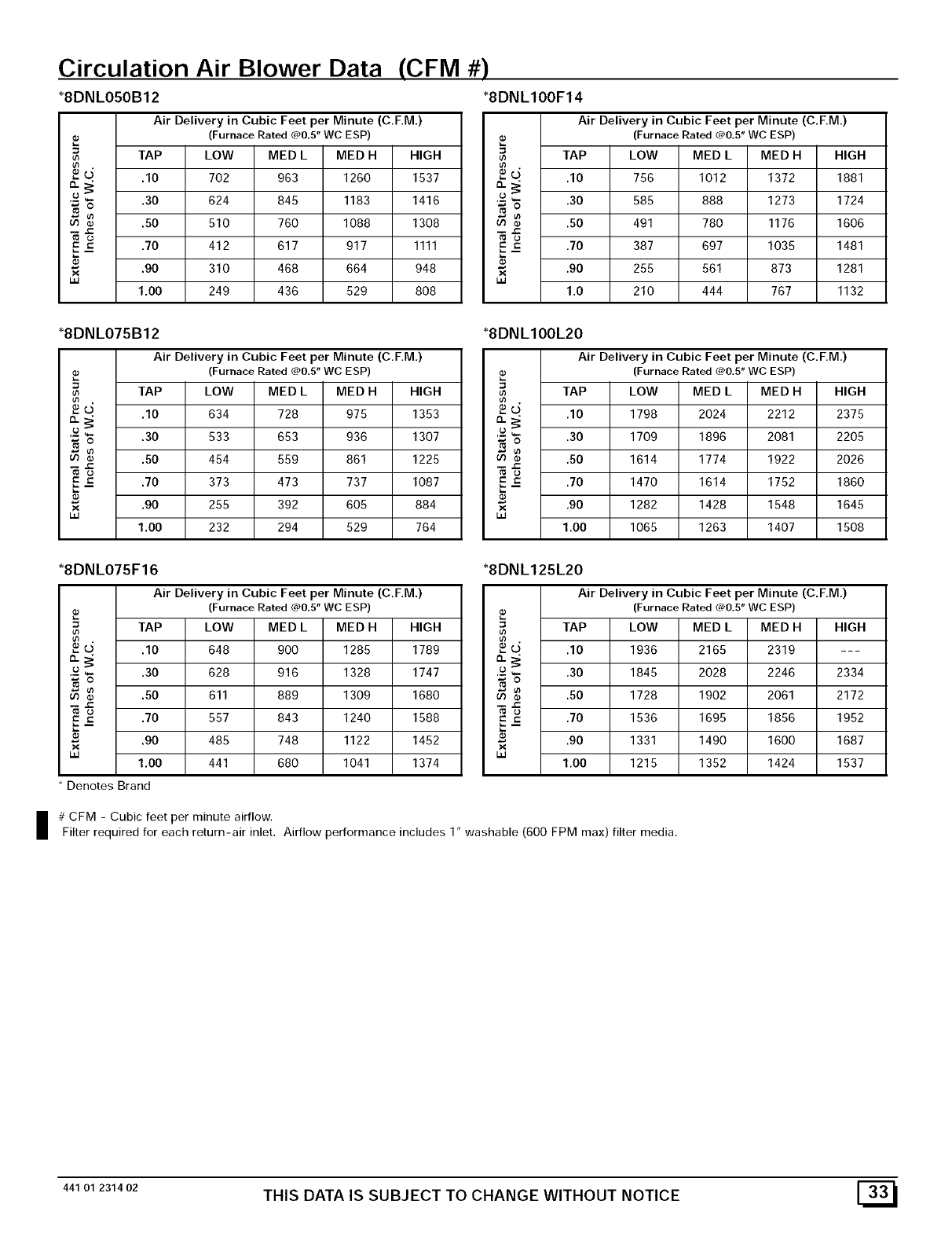
Circulation Air Blower Data (CFM #)
*8DNLO50B12 *8DNLIOOF14
Air Delivery in Cubic Feet per Minute (C.F.M.)
(Furnace Rated @0.5" WC ESP)
TAP LOW MED L MED H HIGH
_-_5, .10 702 963 1260 1537
,£ ,30 624 845 1183 1416
No
_ .60 510 760 1088 1308
=u ,70 412 617 917 1111
•_ .90 310 468 664 948
uJ 1,00 249 436 529 808
*8DNLO75B12
Air Delivery in Cubic Feet per Minute (C.F.M,)
(Furnace Rated @0.5" WC ESP)
TAP LOW MED L MED H HIGH
•_O' ,10 634 728 975 1353
'£ .30 533 653 936 1307
_o_,50 454 559 861 1225
=u .70 373 473 737 1087
"_ ,90 255 392 605 884
ua 1,00 232 294 529 764
*8DNL075F16
Air Delivery in Cubic Feet per Minute (C.F.M.)
(Furnace Rated @0.5" WC ESP)
=TAP LOW MED L MED H HIGH
5 .10 648 900 1285 1789
,£ ,30 628 916 1328 1747
_ .50 611 889 1309 1680
=u ,70 557 843 1240 1588
.90 485 748 1122 1452
x
_J 1,00 441 680 1041 1374
• Denotes Brand
Air Delivery in Cubic Feet per Minute (C.F.M.)
(Furnace Rated @0.5" WC ESP)
TAP LOW MED L MED H HIGH
_-_5, .10 756 1012 1372 1881
,£ ,30 585 888 1273 1724
No
_ .50 491 780 1176 1606
=u ,70 387 697 1035 1481
x .90 255 561 873 1281
uJ 1.0 210 444 767 1132
*8DNL100L20
Air Delivery in Cubic Feet per Minute (C.F.M,)
(Furnace Rated @0.5" WC ESP)
TAP LOW MED L MED H HIGH
•_ O' ,10 1798 2024 2212 2375
'-£ .30 1709 1896 2081 2205
To _ ,50 1614 1774 1922 2026
=u .70 1470 1614 1752 1860
x ,90 1282 1428 1548 1645
uJ 1.00 1065 1263 1407 1508
*8DNL125L20
Air Delivery in Cubic Feet per Minute (C.F.M.)
(Furnace Rated @0.5" WC ESP)
=TAP LOW MED LMED H HIGH
5 .10 1936 2165 2319 ---
,£ ,30 1845 2028 2246 2334
_ .50 1728 1902 2061 2172
=u ,70 1536 1695 1856 1952
.90 1331 1490 1800 1687
x
_J 1.00 1215 1352 1424 1537
I # CFM -Cubic feet per minute airflow.
Filter required for each return-air inlet. Airflow performance includes 1" washable (600 FPM max) filter media.
44101231402 THIS DATA IS SUBJECT TO CHANGE WITHOUT NOTICE [_
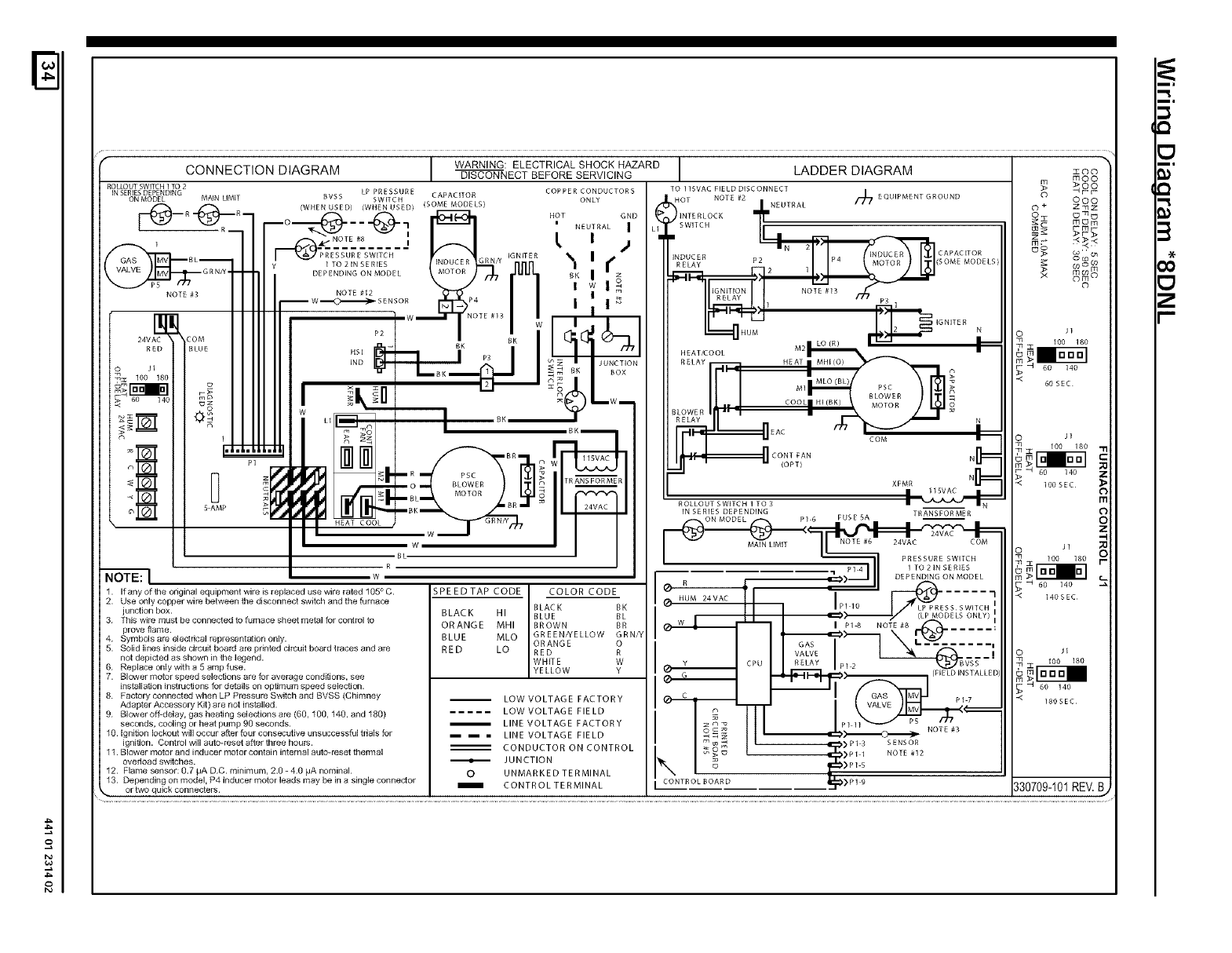
2
4_
o
f
CONNECTION DIAGRAM DISCONNECT BEFORE SERVICING
ROLLOUTSWITCH1TO2
'NSE_hSM_D'NGM_NL'M'T _VSsSE _.,,T&.E O.LY
--I--(_)--_.R7_o--_-(_--..(:_-, _ HOTNEUTRALG,D
NOTE #g | I
I -_'_¢JSTET_'U_E--S;_--.----_NDU(ER % GRN/Y IGNITER %" I "
y I TO 21N SERIES _ nN_ | I"
DEPENDINGON MODEL MOTOR /_ JUUL BK I Z
.OTE._ %-_ ''_l °
--W_SENSOR I_;]_P4 II _
,..-t wr:-r2
IIND -- • _ _ IJUNCTION
_:= 100 18( I×. =11 _ :ZoJ_
_1_1_- _i I_1__U _(>X)_w_
x_'_' _ I_7.g I_--,
_ _ _I_-- _ _ TR_R
_ _
2 ,'_"-_ _ MOTOR _ "m,',,",,-
_
, HEAT_OO:"'--WW ]- .....'-*'
I R BL"
- w
LP PRESSURE CAPACITOR COPPER CONDUCTORS
(WHEN USED) (WHEN USED) (SOME MODELS)
1. If any of the original equipment wire is replaced use wire rated 105° C.
2. Use only copper wire between the disconnect switch and the furnace
junction box.
3. This wire must be connected to furnace sheet metal for contlol to
prove flame.
4. Symbols are electdcat representation only.
5. Solid lines inside circuit board are printed circuit board tlaces and are
not depicted as shown in the legend.
6. Replace only with a 5 amp fuse.
7. Blower motor speed selections are for average conditions, see
installation taatrdctions for details on optimum speed selection.
8. Factory connected when LP Pressure Switch and BVSS (Chimney
Adapter Accessory Kit) are not installed.
9. Btawer off-delay, gas heating selections are (60, 100,146, and 180)
seconds, cooling or heat pump 90 seconds.
10. Ignition lockout will occur after four consecutive unsuccessful tdals for
ignition. Control will auto-reset after three hours.
11. Blower motor and inducer motor contain internal auto-reset thermal
overload switches.
12. Flame sensor: 0.7 pA D.C. minimum, 2.0 - 4.0 pA nominal.
13. Depending on model, P4 inducer motor leads may be in a single connector
WARNING: ELECTRICAL SHOCK HAZARD LADDER DIAGRAM =oo "
m moo
> >00
OT J.NEUTRAL _ _
H NOTE #2 EQUIPMENT GROUND _ Oo O
©+ Zmz
L1_-"V/'sNwT,_T_C'H°oK 7 ]- _:CO:E mr_m_mr_
Zr_ :<>_<
• n 2 "" fT_NDU_ER_I_1CAPACITOR m_ o_:<"
INDUCER P4 _ © _ _
RELAY P2 (SOME MODELS _ o
m_rn
_ ]_.- _ _ :: _ om o
I IGNI,T_ON INOTT#13 /'_ ... C)
IP3 1
RELAY -- HEAT MHI (O)
MLO (BL) _> _< 60 SEC
M1 PSC
_LOWER 9_
RELAY _EAC _ IN
COM • O J1
I._. .q,o_t, U= _ ,oo,_o
., CONT FAN NL _ Z
_m
XF _ 100SEC
Ill
SPEEDTAP CODE COLOR CODE
BLACK BK
BLACK HI BLUE BL
ORANGE MHI BROWN BR
BLUE MLO GREEN/YELLOW GRN/Y
ORANGE O
RED LO RED R
WHITE W
YELLOW Y
LOW VOLTAGE FACTORY
LOW VOLTAGE FIE LD
LINE VOLTAGE FACTORY
i i . LINE VOLTAGE FIELD
CONDUCTOR ON CONTROL
JUNCTION
O UNMARKED TERMINAL
I CONTROL TERMINAL
TO 115VAC FIELD DISCONNECT
ROLLOUT SWITCH 1 TO3
IN SE RIES DEPENDING TRANSFOR MER
ON MODEL P1 6 FUSE 5A --
MAIN LIMIT NOTE #6 24VAC COM J 1 _O
I .... _,4 ,TO_INSERIE__J_l-a
P SS SWITCH
-4_1/ (LPMODELS ONLY)
I P1 8 NOTE#8 ,_
GAS .... ,
VALVE ___! OJ1
CPU RELAY BVSS _q m_ 100 180
_C _zO_Z_--_ i _--_ I1___1_'-- _" _NOTE #3(FIELDINSTALLED _ _
m_m_ _)P13 SENSOR
[ CONTROL_OARD ._=_>_]
B
8
z_
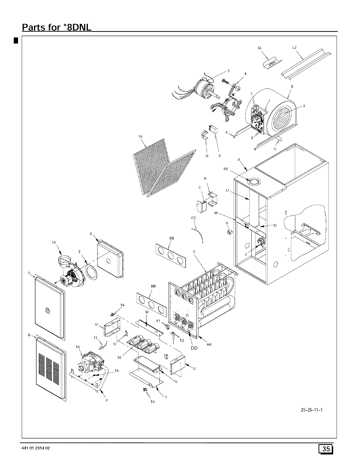
II
Parts for *8DNL
18 \
19
BB
CC
6
A\
KK
JJ
O
BB
\
16
DD AA
25-25-11-1
441 01 231402 [_
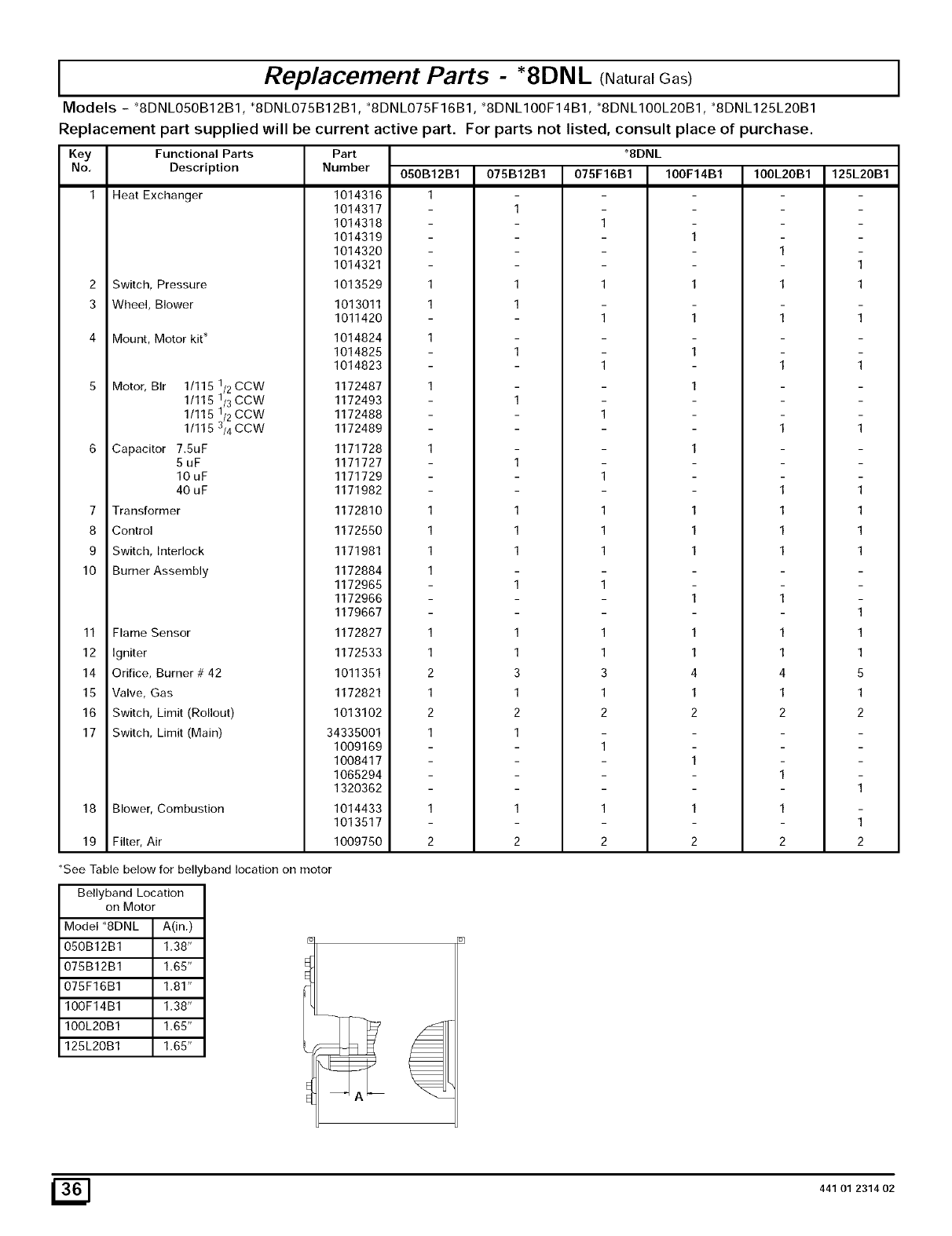
IReplacement Parts - *8DNL (Natural Gas) I
Models - *8DNLO50B12B1, *SDNLO75B12B1, *SDNLO75F16B1, *8DNL100F14B1, *SDNLIOOL2OB1, *SDNL125L20B1
Replacement part supplied will be current active part. For parts not listed, consult place of purchase.
Key Functional Parts Part
No, Description Number
Heat Exchanger
2 Switch, Pressure
3 Wheel, Blower
4 Mount, Motor kit*
5 Motor, BIr 1/115
1/115
1/115
1/115
6 Capacitor 7.SuF
5uF
10uF
40 uF
7 Transformer
8 Control
9 Switch, Interlock
10 Burner Assembly
1/2 COW
1/3 COW
1/2 COW
3/4 CCW
11 Flame Sensor
12 Igniter
14 Orifice, Burner # 42
15 Valve, Gas
16 Switch, Limit (Rollout)
17 Switch, Limit (Main)
18 Blower, Combustion
19 Filter, Air
*See Table below for bell,
Bellyband Location
on Motor
Model *8DNL A(in.)
O50B12B1 1.38"
075B12B1 1.65"
075F16B1 1.81"
100F14B1 1.38"
100L20B1 1.65"
125L20B1 1.65"
1014316
1014317
1014318
1014319
1014320
1014321
1013529
1013011
1011420
1014824
1014825
1014823
1172487
1172493
1172488
1172489
1171728
1171727
1171729
1171982
1172810
1172550
1171981
1172884
1172965
1172966
1179667
1172827
1172533
1011351
1172821
1013102
34335001
1009169
1008417
1065294
1320362
1014433
1013517
1009750
050B12B1
1
1
1
1
1
1
1
1
1
2
1
2
1
1
2
075B12B1
1
1
1
1
1
1
1
1
3
1
2
1
1
2
*8DNL
075F16B1 100F14B1
1
1
1 1
1 1
1
1
1
1
1
1
1 1
1 1
1 1
1
1
1 1
1 1
3 4
1 1
2 2
1
1
1 1
2 2
band location on motor
100L20B1
1
1
1
1
1
1
1
1
1
4
1
2
1
1
2
125L20B1
1
1
1
1
1
1
1
1
1
5
1
2
1
1
2
441 01 231402
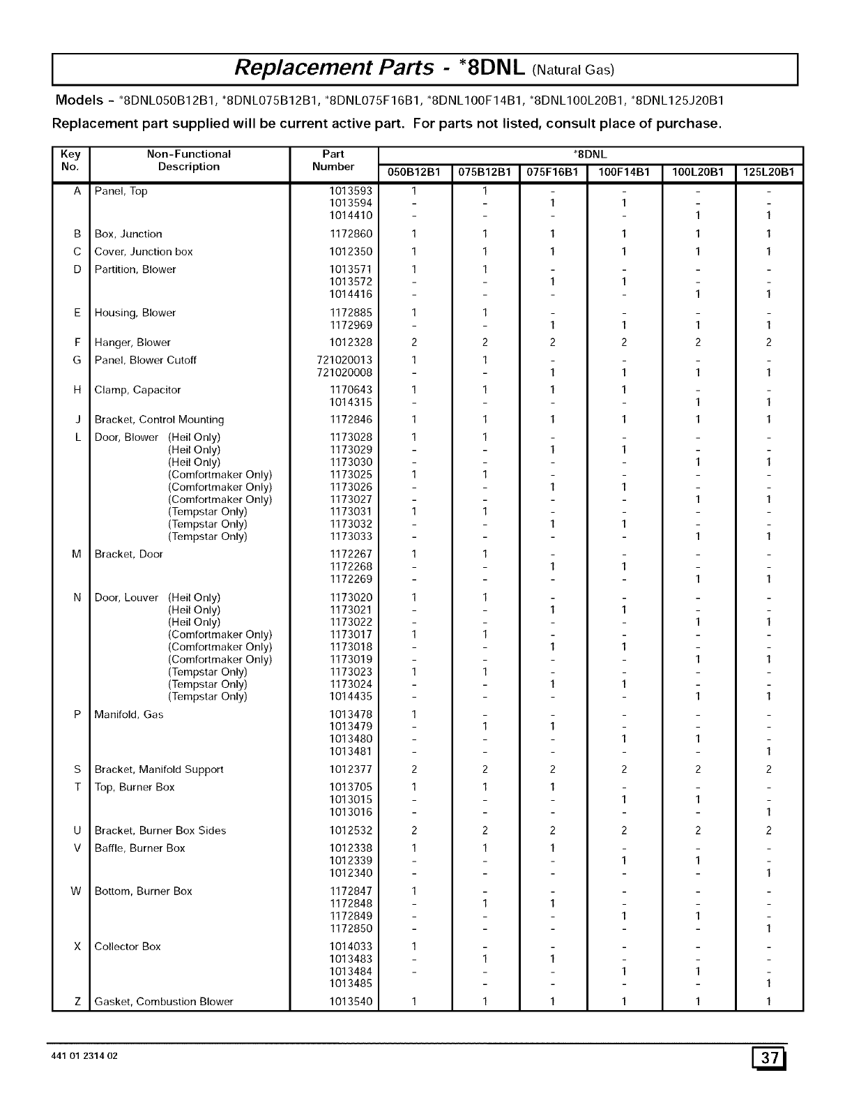
IReplacement Parts - *8DNL (Natural Gas) I
Models - "8DNL050B12B1, *8DNL075B12B1, *8DNL075F16B1, "8DNL100F14B1, *8DNL100L20B1, *8DNL125J20B1
Replacement part supplied will be current active part. For parts not listed, consult place of purchase.
Key Non-Functional Part
No, Description Number 100L20B1 125L20B1
Panel, Top
B Box, Junction
C Cover, Junction box
D Partition, Blower
E
F
G
H
J
L
Housing, Blower
Hanger, Blower
Panel, Blower Cutoff
Clamp, Capacitor
Bracket, Control Mounting
Door, Blower (Hell Only)
(Hell Only)
(Hell Only)
(Comfortmaker Only)
(Comfortmaker Only)
(Comfortmaker Only)
(Tempstar Only)
(Tempstar Only)
(Tempstar Only)
Bracket, Door
Door, Louver (Hell Only)
(Hell Only)
(Hell Only)
(Comfortmaker Only)
(Comfortmaker Only)
(Comfortmaker Only)
(Tempstar Only)
(Tempstar Only)
(Tempstar Only)
Manifold, Gas
S Bracket, Manifold Support
T Top, Burner Box
U Bracket, Burner Box Sides
V Baffle, Burner Box
W Bottom, Burner Box
Collector Box
1013593
1013594
1014410
1172860
1012350
1013571
1013572
1014416
1172885
1172969
1012328
721020013
721020008
1170643
1014315
1172846
1173028
1173029
1173030
1173025
1173026
1173027
1173031
1173032
1173033
1172267
1172268
1172269
1173020
1173021
1173022
1173017
1173018
1173019
1173023
1173024
1014435
1013478
1013479
1013480
1013481
1012377
1013705
1013015
1013016
1012532
1012338
1012339
1012340
1172847
1172848
1172849
1172850
1014033
1013483
1013484
1013485
1013540
050B12B1
1
1
1
1
1
2
1
1
1
1
1
1
1
1
2
1
2
1
Z Gasket, Combustion Blower 1
441 01 231402
078B12B1
1
1
1
1
1
2
1
1
1
1
1
1
1
2
1
2
1
1
1
*8DNL
078F16B1 100F14B1
1 1
1 1
1 1
1 1
1 1
2 2
1 1
1 1
1 1
1 1
1 1
1 1
1 1
1 1
1 1
1 1
1
1
2 2
1
1
2 2
1
1
1
1
1
1
1 1
1
1
1
1
1
2
1
1
1
1
1
1
1
2
1
2
1
1
1
1
1
1
1
1
2
1
1
1
1
1
1
1
2
1
2
1
1
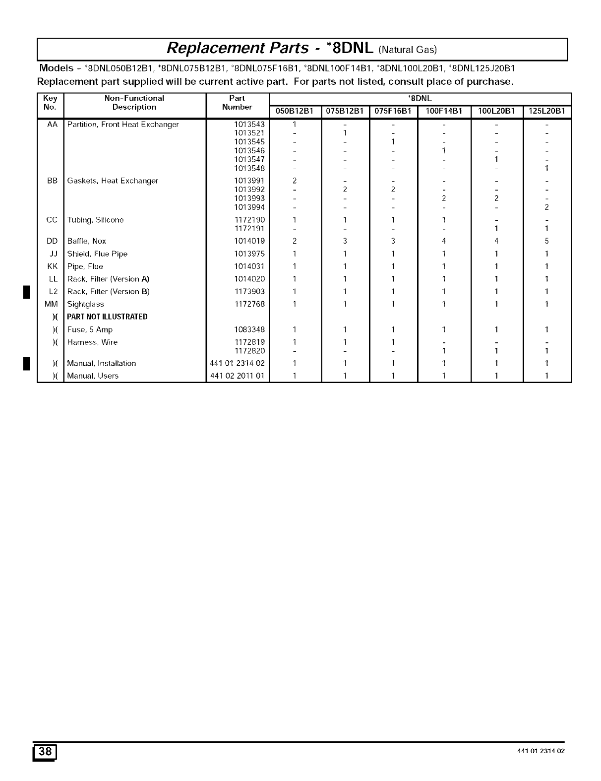
IReplacement Parts - "8DNL (Natural Gas) I
Models - "8DNLO50B12B1, 'SDNLO75B12B1, 'SDNLO75F16B1, "8DNL100F14B1, '8DNLIOOL2OB1, 'SDNL125J20B1
Replacement part supplied will be current active )art. For parts not listed, consult place of purchase.
Key Non-Functional Part
No, Description Number
AA Partition, Front Heat Exchanger
BB Gaskets, Heat Exchanger
CC Tubing, Silicone
DD
JJ
KK
LL
I L2
MM
)(
)(
)(
)(
1013543
1013521
1013545
1013548
1013547
1013548
1013991
080B12B1
1
075B12B1
1
"SDNL
075F16B1 100F14B1
1
1
100L20B1
Baffle, Nox
Shield, Flue Pipe
Pipe, Flue
Rack, Filter (Version A)
Rack, Filter (Version B)
Sightglass
PARTNOT ILLUSTRATED
Fuse, 5 Amp
Harness, Wire
Manual, Installation
Manual, Users
1013992
1013993
1013994
1172190
1172191
1014019
1013975
1014031
1014020
1173903
1172768
1083348
1172819
1172820
441 01 2314 02
441 02 2011 01
2
1
1
1
1
1
1
1
1
1
3
1
1
1
1
1
1
1
1
1
3
1
1
1
1
1
1
1
1
1
4
1
1
1
1
1
1
1
1
1
4
1
1
1
1
1
1
1
1
125L20B1
1
5
1
1
1
1
1
1
1
1
_] 441 01 231402
