ICP C8DNL100F14A1 User Manual 80+ SINGLE STAGE GAS FURNACE Manuals And Guides L0502521
ICP Furnace/Heater, Gas Manual L0502521 ICP Furnace/Heater, Gas Owner's Manual, ICP Furnace/Heater, Gas installation guides
User Manual: ICP C8DNL100F14A1 C8DNL100F14A1 ICP 80+ SINGLE STAGE GAS FURNACE - Manuals and Guides View the owners manual for your ICP 80+ SINGLE STAGE GAS FURNACE #C8DNL100F14A1. Home:Heating & Cooling Parts:Icp Parts:Icp 80+ SINGLE STAGE GAS FURNACE Manual
Open the PDF directly: View PDF ![]() .
.
Page Count: 16
Condensing Gas urnaces
90+ Four Position Furnaces
N9MP1, N9MP2, *9MPD, *9MPT &*9MPV
Non-Condensing Gas urnaces
80+ Four Position Furnaces
N8MPN/L, *8MPN/L, *8MPT &*8MPV
*8DNL (Downflow only)
Installer: Affix these instructions
on or adjacent to the furnace.
Consumer: Retain these
instructions for future reference.
FIRE OR EXPLOSION HAZARD.
Failure to follow safety warnings
exactly could result in death, serious
injury and/or property damage.
-- Do not store or use gasoline or other
flammable vapors and liquids in the
vicinity of this or any other appliance.
-- WHAT TO DO IF YOU SMELL GAS
•Do NOT try to light any appliance.
°Do NOT touch any electrical switch; do
NOT use any phone in your building.
°Leave the building immediately
°Immediately call your gas supplier from a
neighbor's phone. Follow the gas supplier's
instructions.
°If you cannot reach your gas supplier, call
the fire department.
-- Installation and service must be performed by
a qualified installer, service agency or the gas
supplier.
International Comfort Products, LLC
Lewisburg, TN 37097
PrintedinU.S.A. (06/28/2004) 441 02 2010 04
User's Information Manual
Contents
Danger, Warning and Caution ................ 2
Safety Rules ............................. 3
Combustion Air (Your Safety) ................ 4
Indoor Humidity (Your Comfort) .............. 5
About Your Furnace ....................... 5
Operating Your Furnace .................... 8
Furnace Maintenance ...................... 9
Warranty ............................... 15
Danger,Warning
Recognize safety information.
This is the safety-alert symbol A. When you see this symbol
on the furnace and in instruction manuals be alert to the potential
for personal injury.
Understand the signal words DANGER, WARNING and CAU-
TION. These words are used to identify levels of hazard serious-
ness. The signal word DANGER is only used on product labels to
signify an immediate hazard. The signal words WARNING and
CAUTION will be used on product labels and throughout this
manual and other manuals that may apply to the product.
Signal Words
DANGER - Immediate hazards which WILL result in severe per-
sonal injury or death.
WARNING - Hazards or unsafe practices which COULD result in
severe personal injury or death.
CAUTION - Hazards or unsafe practices which MAY result in mi-
nor personal injury or product or property damage.
"NOTE" is used to highlight suggestions which will result in en-
hanced installation, reliability or operation.
Signal Words in Manuals
The signal word WARNING is used throughout this manual in the
following manner:
and Caution
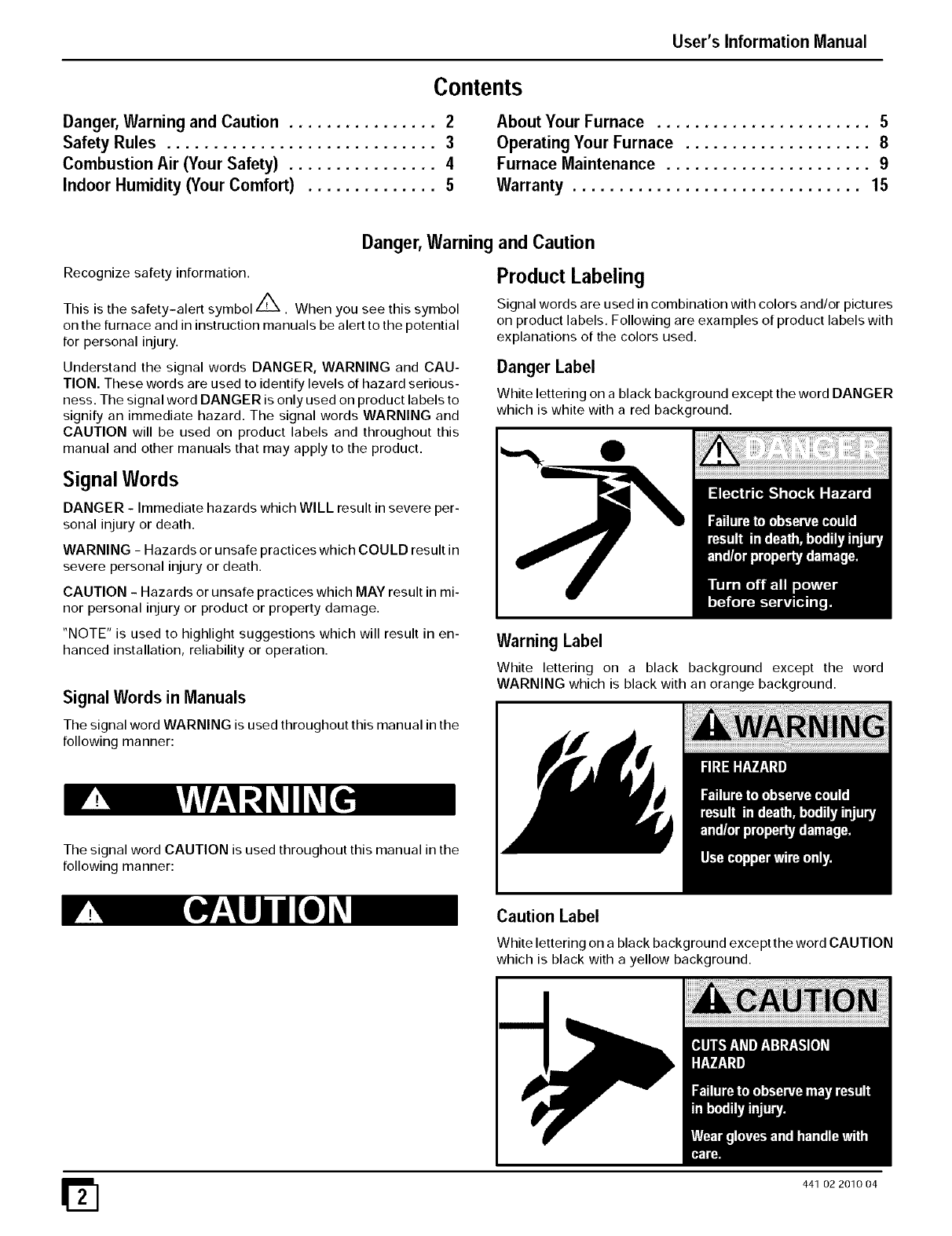
Product Labeling
Signal words are used in combination with colors and/or pictures
on product labels. Following are examples of product labels with
explanations of the colors used.
Danger Label
White lettering on a black background except the word DANGER
which is white with a red background.
Warning Label
White lettering on a black background except the word
WARNING which is black with an orange background.
The signal word CAUTION is used throughout this manual in the
following manner:
Caution Label
White lettering on a black background except the word CAUTION
which is black with a yellow background.
441 02 2010 04
User's Information Manual
DEATH, PERSONAL INJURY AND/OR PROPERTY
DAMAGE HAZARD
Failure to observe and follow Cautions, Warnings
and instructions could result in death, bodily
injury or property damage.
Read this manual and follow its instructions and
adhere to all Cautions and Warnings in the manual
and on the furnace.
Consult a qualified service agency for
installation, adjustment and maintenance.
SafetyRules
Your furnace is built to provide many years of safe and depend-
able service providing it is properly installed and maintained.
However,abuse and/or improper use can shorten the life of the
furnace and create hazards for you, the owner.
A. The U.S. Consumer Product Safety Commission recom-
mends that users of gas-burning appliances install carbon
monoxide detectors. There can be various sources of car-
bon monoxide in a building or dwelling. The sources could
be gas-fired clothes dryers, gas cooking stoves, water
heaters, furnaces, gas-fired fireplaces, wood fireplaces,
and several other items. Carbon monoxide can cause seri-
ous bodily injury a nd/or death. Carbon monoxide or"CO" is
a colorless and odorless gas produced when fuel is not
burned completely or when the flame does not receive suf-
ficient oxygen.
Therefore, to help alert people of potentially dangerous
carbon monoxide levels, you should have carbon monox-
ide detectors that are listed as complying with a standard
by a nationally recognized agency (e.g. ANSI/UL
2034-2002, CSA 6.19-01, or International Approval Ser-
vices 6-96) installed and maintained in the building or
dwelling (see Note below).
B. There can be numerous sources of fire or smoke in a build-
ing or dwelling. Fire or smoke ca n cause serious bodily inju-
ry, death, and/or property damage. Therefore, in order to
alert people of potentially dangerous fire or smoke, you
should have fire and smoke detectors that are listed by Un-
derwriters Laboratories installed and maintained in the
building or dwelling (see Note below).
Note: The manufacturer of your furnace does not test any de-
tectors and makes no representations regarding any brand
or type of detector.
C. To ensure safe and efficient operation of your furnace, you
should do the following:
1. Thoroughly read this manual and labels on the fur-
nace. This will help you understand how your furnace oper-
ates and the hazards involved with gas and electricity.
2. The furnace area must be kept clear and free of com-
bustible materials, gasoline, and other flammable va-
pors and liquids.
3. Do not use this furnace if any part has been underwa-
ter. A flood-damaged furnace is extremely dangerous. At-
tempts to use the furnace can result in fire or explosion.
Immediately call a qualified service agency to inspect the
furnace and to replace all control system parts, electrical
parts, and gas controls which have been wet or the furnace,
if deemed necessary.;
441 02 201004
4. Never block or obstruct the openings on the furnace,
or any ducts that provide air to the furnace. Air must be
provided for proper and safe operation of the furnace for
combustion and ventilation of flue gases. See the "Com-
bustion Air (Your Safety) section of this manual.
5. Familiarize yourself with the possible air starvation
signals. These are outlined in the Combustion Air section.
6. Check the combustion air supply. Some models use air
drawn from outdoors, See Figure 4. Other models and oth-
er appliances use combustion air from inside the structure.
Air starvation signals are given in the following "Combus-
tion Air (Your Safety)" section of this manual. If any of the
signals are noticed, perform a combustion air check as
shown in the following Combustion Air Checks section of
this manual or call a qualified service agency. If you add
weather stripping, storm windows, insulation, an additional
fuel burning appliance, or remodel the structure, a combus-
tion air check MUST be accomplished after the addition
7. Maintain safety and service clearances from the fur-
nace. These clearances are listed on the furnace rating
plate. Keep the furnace area clean and free of combustible
materials at all times. Never store gasoline, paint, aerosol
cans, waxes, bleaches, dry cleaning fluid or items such as
paper or rags near the furnace.
8. Examine the furnace area when the furnace or addi-
tional insulation is added since some insulation mate-
rials may be combustible. Furnace must be kept free and
clear of exposed or loose insulation materials in the area of
installation.
9. Check the return air duct connection. The duct connec-
tion must be physically sound, sealed to the furnace casing
and must terminate outside the space containing the fur-
Race.
10.Should the gas supply fail to shut off or if overheating
occurs, shut off the gas valve to the furnace before
shutting offthe electrical supply. Read the label on the
front of the furnace and the Operating Your Furnace sec-
tion of this manual for steps to turn off the furnace.
11 .Familiarize yourself with all controls. Make sure you
know how to shut off the gas and the electrical power to the
furnace. Read the label on the front of the furnace and the
Operating Your Furnace section of this manual for steps to
start and turn off the furnace. If the furnace is to be shut
down for an extended length of time (example; remodeling
project), turn off both the gas and the electrical power. For
safety, always turn them off before performing service or
maintenance on the furnace.
12. Establish a regular service and maintenance sched-
ule. This will ensure efficient and safe operation of the fur-
nace. It is recommended that you have a qualified service
agency perform a complete check on the furnace before
each heating season. See furnace Qualified Agency
Checks and Combustion Air Checks section of this manu-
al.
13. Monthly Inspection. A properly adjusted gas furnace
should not require cleaning at frequent intervals, but it
should be inspected regularly to ensure safe and efficient
operation. A brief monthly inspection is recommended that
does not require disassembly. Examine the furnace instal-
lation to determine that:
a. All flue gas carrying areas external to the furnace (i.e.
chimney, vent connector) are clear and free of obstruc-
tions.
b. The vent connector is in place, slopes upward and is
sound without holes or excessive corrosion.
User's Information Manual
c. (Upflow or downflow installations with duct connection
at bottom only.) The physical support of the furnace is
sound without sagging, cracks, gaps, etc., around the
base so as to provide an air seal between the support
and the base.
d. There should be no obvious signs of deterioration of the
furnace.
e. Check that the pilot and burner flames are in good ad-
justment. To inspect the Pilot and Main Burner flames it
will be necessary to remove the Iouvered door on the
front of the furnace, except for furnaces not having any
louvers in the doors. The doors of these furnaces must
remain installed (to prevent changes in flame appear-
ance) while inspecting the Pilot and Main Burner flames
through the view port in the door. Contact a qualified
service agency at once if an abnormal flame appear-
ance is identified.
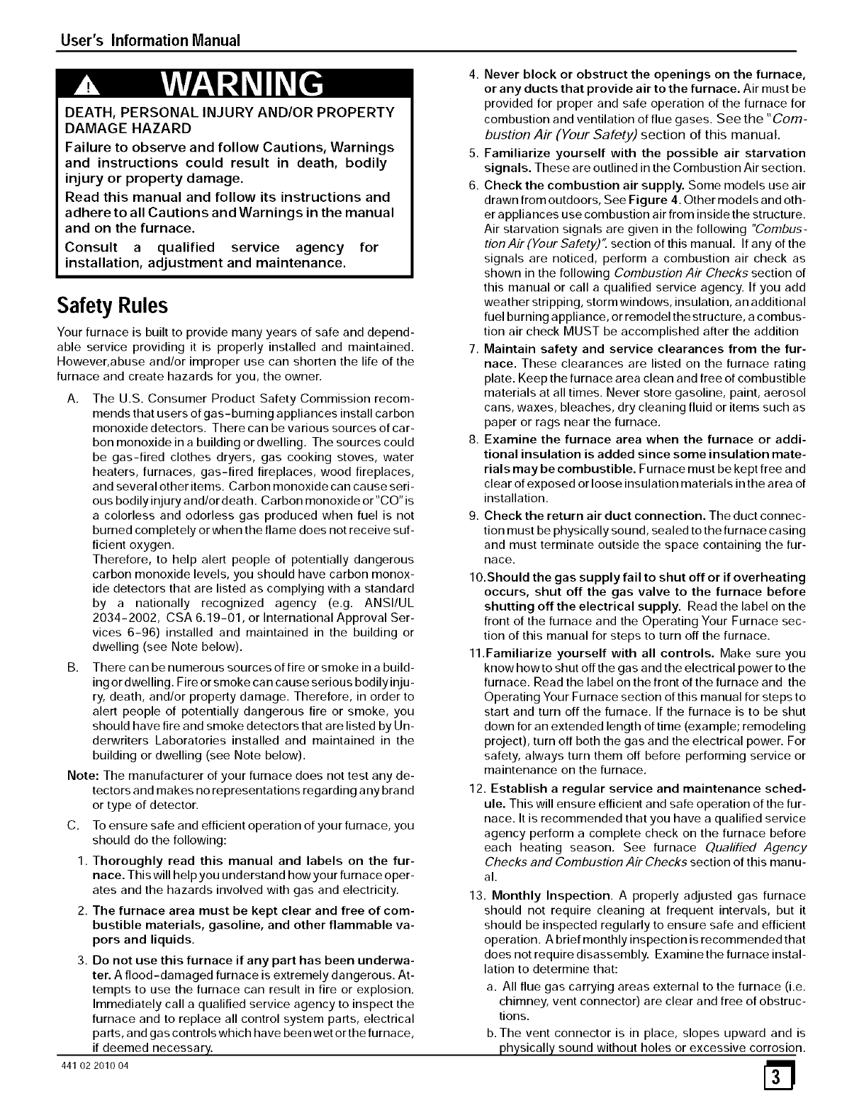
Main Burner Flame: Check for the following:
• Stable and blue flames. See Figure 1.
• Flames extending directly from burner into heat
exchanger.
• Flames do NOT touch sides of heat exchanger.
NOTE: Dust may cause orange tips or wisps of yellow, but flames
MUST NOT have solid, yellow tips.
Main Burner
Face
10-10-78
• Check main burner flames monthly.
• Check main burner flames monthly.
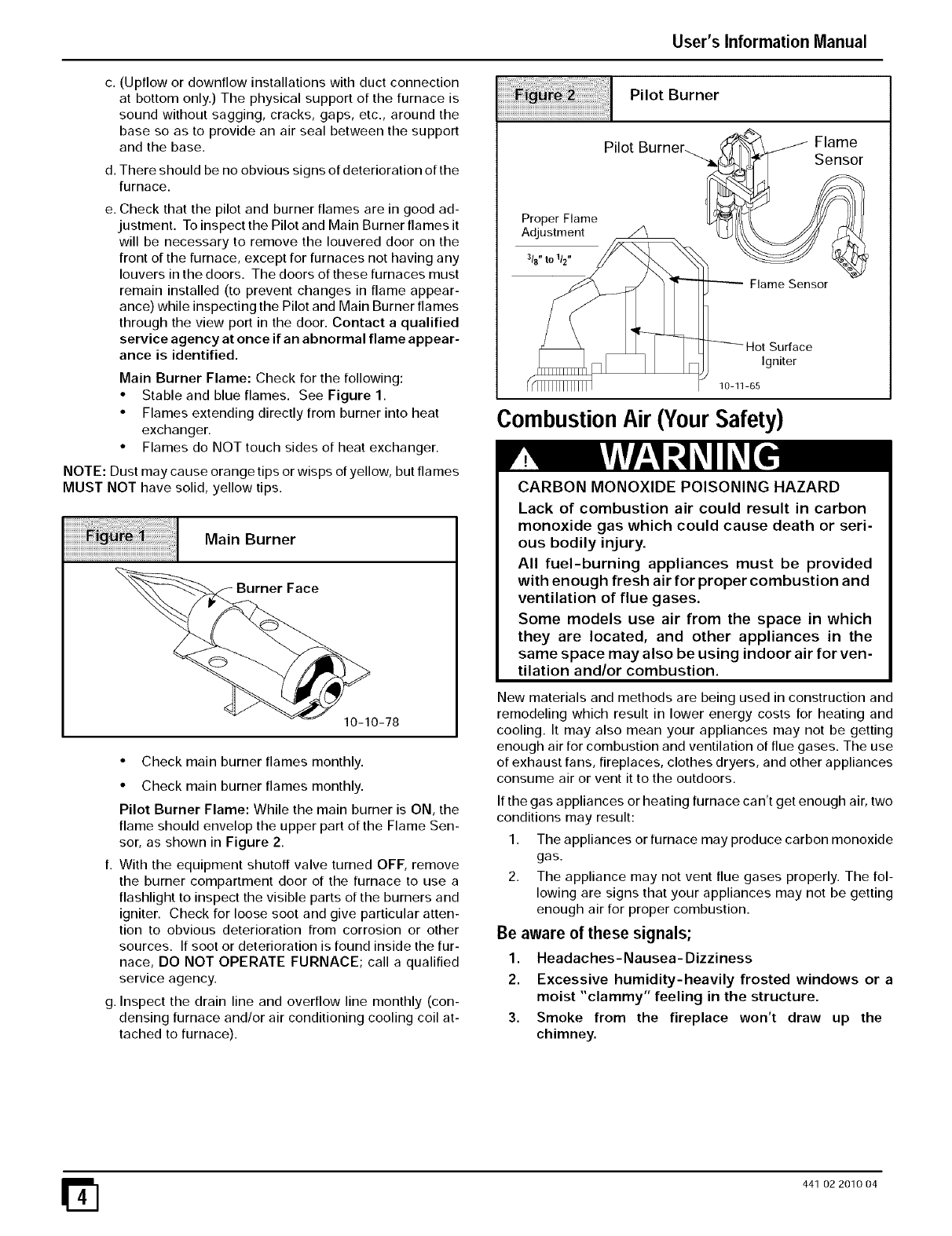
Pilot Burner Flame: While the main burner is ON, the
flame should envelop the upper part of the Flame Sen-
sor, as shown in Figure 2.
f. With the equipment shutoff valve turned OFF, remove
the burner compartment door of the furnace to use a
flashlight to inspect the visible parts of the burners and
igniter. Check for loose soot and give particular atten-
tion to obvious deterioration from corrosion or other
sources. If soot or deterioration is found inside the fur-
nace, DO NOT OPERATE FURNACE; call a qualified
service agency.
g. Inspect the drain line and overflow line monthly (con-
densing furnace and/or air conditioning cooling coil at-
tached to furnace).
Pilot Burner
Pilot
Proper Flame
Adjustment
3t8"1o1t2"
----- Flame Sensor
Hot Surface
Igniter
10-11-65
Combustion Air (Your Safety)
Flame
Sensor
CARBON MONOXIDE POISONING HAZARD
Lack of combustion air could result in carbon
monoxide gas which could cause death or seri-
ous bodily injury.
All fuel-burning appliances must be provided
with enough fresh air for proper combustion and
ventilation of flue gases.
Some models use air from the space in which
they are located, and other appliances in the
same space may also be using indoor air for ven-
tilation and/or combustion.
New materials and methods are being used in construction and
remodeling which result in lower energy costs for heating and
cooling. It may also mean your appliances may not be getting
enough air for combustion and ventilation of flue gases. The use
of exhaust fans, fireplaces, clothes dryers, and other appliances
consume air or vent it to the outdoors.
If the gas appliances or heating furnace can't get enough air, two
conditions may result:
1. The appliances or furnace may produce carbon monoxide
gas.
2. The appliance may not vent flue gases properly. The fol-
lowing are signs that your appliances may not be getting
enough air for proper combustion.
Be aware of these signals;
1. Headaches-Nausea-Dizziness
2. Excessive humidity-heavily frosted windows or a
moist "clammy" feeling in the structure.
3. Smoke from the fireplace won't draw up the
chimney.
441 02 2010 04
User's Information Manual
CARBON MONOXIDE POISONING HAZARD.
Carbon monoxide poisoning could result in death
from asphyxiation or serious bodily injury.
If you experience headaches, nausea, or
dizziness, carbon monoxide may be present.
Leave the house immediately and call your gas
supplier.
Combustion Air Checks
If any of the above signals are noticed, perform a combustion air
check or call a qualified service agency. If you add weather strip-
ping, storm windows, insulation, an additional fuel burning ap-
pliance, or remodel the structure, a combustion air check MUST
be accomplished after the addition.
Make the inspection as follows:
1. Close all doors and windows. If you have a fireplace, start a
fire and wait until flames are burning vigorously.
2. Turn on all exhausting devices, such as: kitchen and bath-
room exhaust fans and dryers (gas or electric).
3. Turn on all vented gas appliances, such as: heating equip-
ment (includes any room heaters) and water heaters.
4. Wait ten (10) minutes for drafts to stabilize.
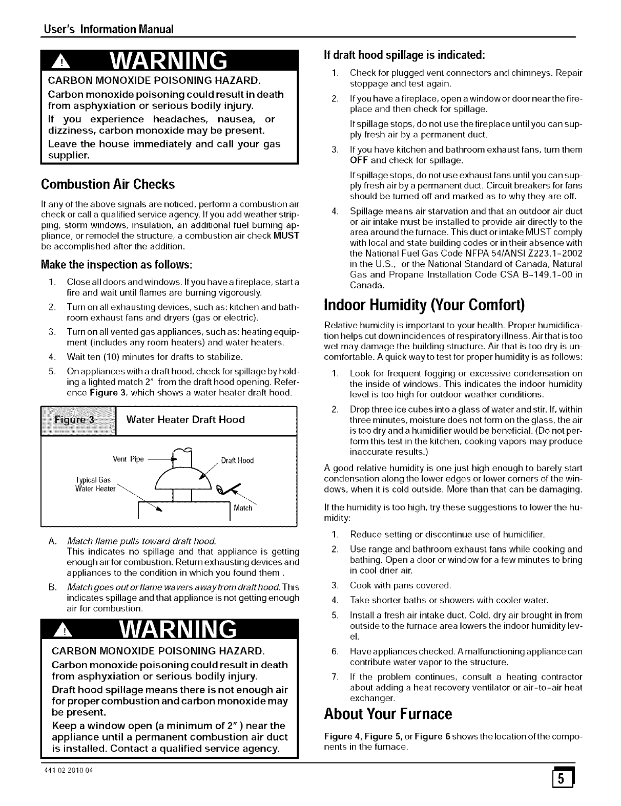
5. On appliances with a draft hood, check for spillage by hold-
ing a lighted match 2" from the draft hood opening. Refer-
ence Figure 3, which shows a water heater draft hood.
Water Heater Draft Hood
Vent Pipe _---L /Draft Hood
f --=/
If draft hood spillage is indicated:
1. Check for plugged vent connectors and chimneys. Repair
stoppage and test again.
2. Ifyou have a fireplace, open a windowor door near the fire-
place and then check for spillage.
If spillage stops, do not use the fireplace until you can sup-
ply fresh air by a permanent duct.
3. If you have kitchen and bathroom exhaust fans, turn them
OFF and check for spillage.
If spillage stops, do not use exhaust fans until you can sup-
ply fresh air by a permanent duct. Circuit breakers for fans
should be turned off and marked as to why they are off.
4. Spillage means air starvation and that an outdoor air duct
or air intake must be installed to provide air directly to the
area around the furnace. This duct or intake MUST comply
with local and state building codes or in their absence with
the National Fuel Gas Code NFPA 54/ANSI Z223.1-2002
in the U.S., or the National Standard of Canada, Natural
Gas and Propane Installation Code CSA B-149.1-00 in
Canada.
IndoorHumidity(YourComfort)
Relative humidity is important to your health. Proper humidifica-
tion helps cut down incidences of respiratory illness. Air that istoo
wet may damage the building structure. Air that is too dry is un-
comfortable. A quick way to test for proper humidity is as follows:
1,
2,
Look for frequent fogging or excessive condensation on
the inside of windows. This indicates the indoor humidity
level is too high for outdoor weather conditions.
Drop three ice cubes into a glass of water and stir. If, within
three minutes, moisture does not form on the glass, the air
is too dry and a humidifier would be beneficial. (Do not per-
form this test in the kitchen, cooking vapors may produce
inaccurate results.)
A good relative humidity is one just high enough to barely start
condensation along the lower edges or lower corners of the win-
dows, when it is cold outside. More than that can be damaging.
If the humidity is too high, try these suggestions to lower the hu-
midity:
A. Match flame pulls toward draft hood.
This indicates no spillage and that appliance is getting
enough air for combustion. Return exhausting devices and
appliances to the condition in which you found them.
B. Match goes out or flame wavers away from draft hood. This
indicates spillage and that appliance is not getting enough
air for combustion.
CARBON MONOXIDE POISONING HAZARD.
Carbon monoxide poisoning could result in death
from asphyxiation or serious bodily injury.
Draft hood spillage means there is not enough air
for proper combustion and carbon monoxide may
1. Reduce setting or discontinue use of humidifier.
2. Use range and bathroom exhaust fans while cooking and
bathing. Open a door or window for a few minutes to bring
in cool drier air.
3. Cook with pans covered.
4. Take shorter baths or showers with cooler water.
5. Install a fresh air intake duct. Cold, dry air brought in from
outside to the furnace area lowers the indoor humidity lev-
el.
6. Have appliances checked. A malfunctioning appliance can
contribute water vapor to the structure.
7. If the problem continues, consult a heating contractor
about adding a heat recovery ventilator or air-to-air heat
exchanger.
be present.
Keep a window open (a minimum of 2" ) near the
appliance until a permanent combustion air duct
is installed. Contact a qualified service agency.
AboutYourFurnace
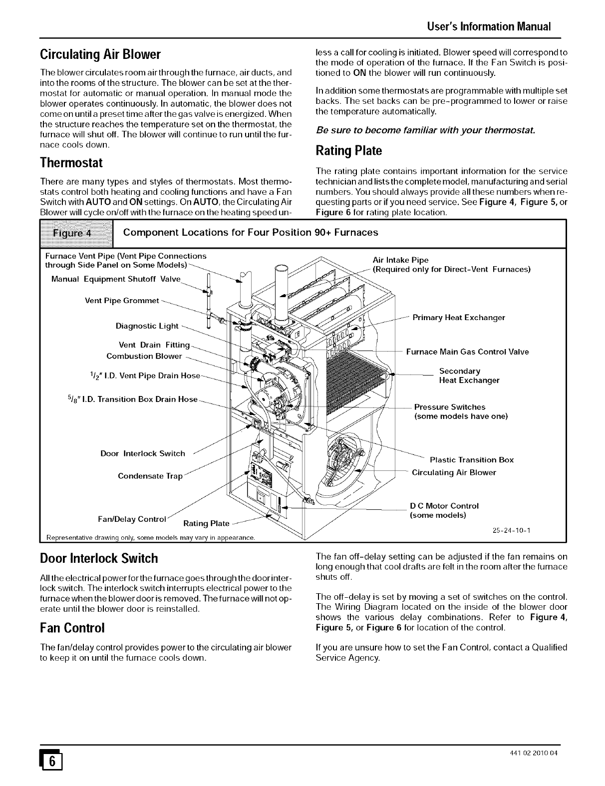
Figure 4, Figure 5, or Figure 6 shows the location of the compo-
nents in the furnace.
441 02 2010 04
User's Information Manual
CirculatingAir Blower
The blower circulates room air through the furnace, air ducts, and
into the rooms of the structure. The blower can be set at the ther-
mostat for automatic or manual operation. In manual mode the
blower operates continuously. In automatic, the blower does not
come on until a preset time after the gas valve is energized. When
the structure reaches the temperature set on the thermostat, the
furnace will shut off. The blower will continue to run until the fur-
nace cools down.
Thermostat
There are many types and styles of thermostats. Most thermo-
stats control both heating and cooling functions and have a Fan
Switch with AUTO and ON settings. On AUTO, the Circulating Air
Blower will cycle on/off with the furnace on the heating speed un-
less a call for cooling is initiated. Blower speed will correspond to
the mode of operation of the furnace. If the Fan Switch is posi-
tioned to ON the blower will run continuously.
In addition some thermostats are programmable with multiple set
backs. The set backs can be pre-programmed to lower or raise
the temperature automatically.
Be sure to become familiar with your thermostat,
Rating Plate
The rating plate contains important information for the service
technician and lists the complete model, manufacturing and serial
numbers. You should always provide all these numbers when re-
questing parts or if you need service. See Figure 4, Figure 5, or
Figure 6 for rating plate location.
iiii I c°mP°nent L°cati°ns f°r F°ur P°siti°n 90+ Furnaces
Furnace Vent Pipe (Vent Pipe Connections Air Intake Pipe
through Side Panel on Some Models (Required only for Direct-Vent Furnaces)
Manual Equipment Shutoff Valve
Vent Pipe Grommet
Diagnostic Primary Heat Exchanger
Vent Drain
Combustion Blower
1/2" I.D. Vent Pi
5/8" I.D. Transition
Furnace Main Gas Control Valve
Secondary
Heat Exchanger
Pressure Switches
(some models have one)
Door Interlock Switch
Condensate Tra I
Plastic Transition Box
Circulating Air Blower
Fan/Delay Rating Plate
Representative drawing only, some models may vary in appearance,
Door Interlock Switch
All the electrical power for the furnace goes through the door inter-
lock switch. The interlock switch interrupts electrical power to the
furnace when the blower door is removed. The furnace will not op-
erate until the blower door is reinstalled.
Fan Control
The fan/delay control provides power to the circulating air blower
to keep it on until the furnace cools down.
D C Motor Control
(some models)
25-24-10-1
The fan off-delay setting can be adjusted if the fan remains on
long enough that cool drafts are felt in the room after the furnace
shuts off.
The off-delay is set by moving a set of switches on the control.
The Wiring Diagram located on the inside of the blower door
shows the various delay combinations. Refer to Figure 4,
Figure 5, or Figure 6 for location of the control.
If you are unsure how to set the Fan Control, contact a Qualified
Service Agency.
441 02 2010 04
User's Information Manual
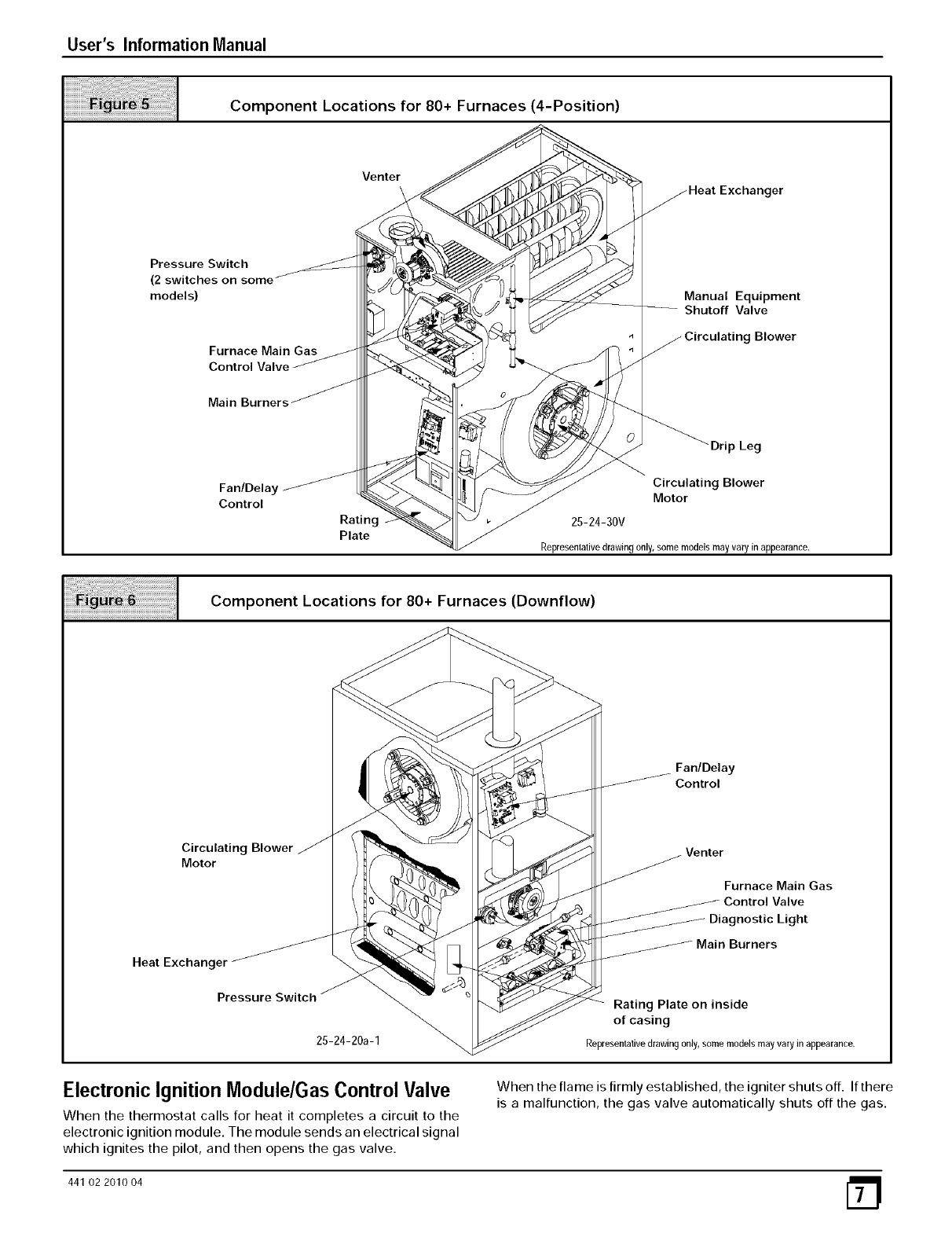
Component Locations for 80+ Furnaces (4-Position)
Venter
get
Pressure Switch
(2 switches on some
models)
Furnace Main Gas
Control Valve
Manual Equipment
Shutoff Valve
Blower
Fan/Delay
Control
Rating
Plate
"Drip Leg
Circulating Blower
Motor
25-24-30V
Representative drawing only,somemodelsmayvaryinappearance.
Component Locations for 80+ Furnaces (Downflow)
Fan/Delay
Control
Circulating Blower
Motor Venter
Furnace Main Gas
Control Valve
Diagnostic Light
Heat Exchanger
Pressure Switch
25-24-20a-1
Rating Plate on inside
of casing
Representativedrawing0nly,some modelsmayvaryin appearance.
Electronic Ignition Module/Gas Control Valve
When the thermostat calls for heat it completes a circuit to the
electronic ignition module. The module sends an electrical signal
which ignites the pilot, and then opens the gas valve.
When the flame is firmly established, the igniter shuts off. If there
is a malfunction, the gas valve automatically shuts off the gas.
441 02 2010 04
User's Information Manual
Pressure Switch
The furnace is equipped with one or more pressure switches to
shut down the furnace under various flue conditions. The
switches are connected to the furnace by factory supplied tubing.
OperatingYourFurnace
Keep the blower access door and all access panels in place ex-
cept for inspection or maintenance.
Before starting your furnace be sure you read and understand all
of the procedures in this manual. Check to make sure the furnace
filter is clean and correctly installed.
CARBON MONOXIDE POISONING HAZARD
Failure to provide adequate combustion and
ventilation air could result in death and/or
personal injury.
Provisions for combustion and ventilation air
must be provided for in accordance with
installation instructions supplied with furnace.
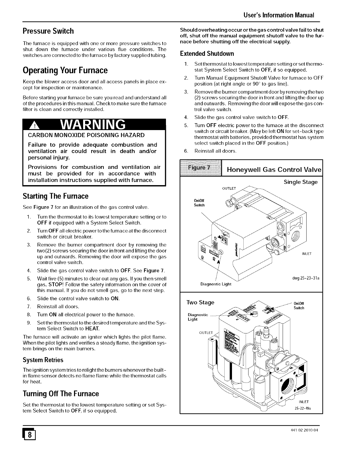
Starting The Furnace
See Figure 7for an illustration of the gas control valve.
1. Turn the thermostat to its lowest temperature setting or to
OFF if equipped with a System Select Switch.
2. Turn OFF all electric power to the furnace at the disconnect
switch or circuit breaker.
3, Remove the burner compartment door by removing the
two(2) screws securing the door in front and lifting the door
up and outwards. Removing the door will expose the gas
control valve switch.
4. Slide the gas control valve switch to OFF. See Figure 7.
5. Wait five (5) minutes to clear out any gas. If you then smell
gas, STOP! Follow the safety information on the cover of
this manual. If you do not smell gas, go to the next step.
6. Slide the control valve switch to ON.
7. Reinstall all doors.
8. Turn ON all electrical power to the furnace.
9. Set the thermostat to the desired temperature and the Sys-
tem Select Switch to HEAT.
The furnace will activate an igniter which lights the pilot flame.
When the pilot lights and verifies a steady flame, the ignition sys-
tem brings on the main burners.
System Retries
The ignition system tries to relight the burners whenever the built-
in flame sensor detects no flame flame while the thermostat calls
for heat.
TurningOff The Furnace
Set the thermostat to the lowest temperature setting or set Sys-
tem Select Switch to OFF, if so equipped.
Should overheating occur or the gas control valve fail to shut
off, shut off the manual equipment shutoff valve to the fur-
nace before shutting off the electrical supply.
Extended Shutdown
1. Set thermostat to lowest temperature setting or set thermo-
stat System Select Switch to OFF, if so equipped.
2. Turn Manual Equipment Shutoff Valve for furnace to OFF
position (at right angle or 90 ° to gas line).
3. Remove the burner compartment door by removing the two
(2) screws securing the door in front and lifting the door up
and outwards. Removing the door will expose the gas con-
trol valve switch.
4,
5.
Slide the gas control valve switch to OFF.
Turn OFF electric power to the furnace at the disconnect
switch or circuit breaker. (May be left ON for set-back type
thermostat with batteries, provided thermostat has system
select switch placed in the OFF position.)
6. Reinstall all doors.
0n\Off
Switch
Honeywell Gas Control Valve
Single Stage
OUTLET
INLET
Diagnostic Light
dwg 25-23-31a
Two Stage
Diagnostic
Light
OUTLET
0n\Off
Switch
INLET
25-22-49a
441 02 2010 04
User's Information Manual
L P Model Furnaces
FIRE OR EXPLOSION HAZARD
Failure to detect and stop gas leak could result in
death, bodily injury, or property damage.
Propane gas is heavier than air. Leaking gas can
settle in low areas such as crawl space. If you
suspect the presence of gas, follow the
instructions on the cover of this manual.
If your L.P. (liquefied petroleum) gas furnace is installed in an ex-
cavated or low lying area, we recommend that you contact your
L.P. gas supplier about installing a warning device that would alert
you of a gas leak.
Frozen Water Pipe Hazard
FROZEN AND BURST WATER PIPE HAZARD.
1. Disconnect the 1/2" I.D. rubber hose from the vent drain fit-
ting (or tee) that is located downstream of the combustion
blower. Insert a funnel into the hose and pour four (4)
ounces of sanitary type (RV) antifreeze into the conden-
sate trap. Reconnect the 1/2" I.D. rubber hose to the stub
on the vent drain fitting. Secure with the hose clamp.
2. Disconnect the 518" I.D. rubber hose from the condensate
trap. Insert a funnel into the hose and pour four (4) ounces
of sanitary type (RV) antifreeze into the plastic transition
box. Squeeze the hose together near the end and quickly
reconnect the 5/8" I.D. rubber hose to the stub on the con-
densate trap. Secure with the hose clamp.
When you return home, your furnace will be ready to start, as it is
not necessary to drain the antifreeze from the furnace.
FurnaceMaintenance
Failure to protect against frozen pipes may result
in burst water pipes, serious property damage
and/or personal injury.
Furnace may shut down. Do not leave your home
unattended for long periods during freezing
weather without turning off water supply and
draining water pipes or otherwise protecting
against the risk of frozen pipes.
Your furnace is designed solely to provide a safe and comfortable
Have your furnace inspected and serviced on an annual basis
(before the heating season) by a qualified service agency.
Labeling
living environment. The furnace is NOT designed to ensure that
water pipes will not freeze. It is equipped with several safety de-
vices that are designed to turn the furnace off and prevent it from
restarting in the event of various potentially unsafe conditions.
If your furnace remains off for an extended time, the pipes in your
home could freeze and burst, resulting in serious water damage.
FIRE OR EXPLOSION HAZARD
Wiring errors can cause improper and dangerous
operation that could result in death, bodily injury,
and/or property damage.
Label all wires prior to disconnection when
servicing controls. Verify proper operation after
servicing. Only qualified service agencies
should attempt electrical service.
If the structure will be unattended during cold weather, you should
take these precautions.
1,
2,
3,
Turn off the water supply to the structure and drain the wa-
ter lines if possible and add an antifreeze for potable water
to drain traps and toilet tanks. Open faucets in appropriate
areas.
-or-
Have someone check the structure frequently during cold
weather to make sure it is warm enough to prevent pipes
from freezing. Instruct them on a qualified service agency
to call to provide service, if required.
-or-
Install a reliable remote sensing device that will notify
somebody of freezing conditions within the home.
Winter Shutdown (90+ Furnaces)
If you go away during the winter months and do not leave the heat
on in your home, the plastic transition box and the condensate
trap on the furnace must be protected from freeze damage. (See
Figure 4)
441 02 201004
Pressure Switches
During regular yearly maintenance, check for cracks in any
tubes on the pressure switches.
ELECTRIC SHOCK HAZARD
Failure to disconnect electricity could result in
death or bodily injury.
Turn off electrical power to furnace before
performing any maintenance or removing panels
or doors.
The air filter(s) should be inspected at least monthly and
cleaned or replaced as required. There are two types of filters
that are commonly used. Washable filters (constructed of alu-
minum mesh, foam, or reinforced fibers) may be cleaned by
soaking in mild detergent and rinsing with water. The fiber-
glass disposable type should be REPLACED before it be-
comes clogged.
Remember that dirty filters are the most common cause of in-
adequate heatinq or coolinq_[oerformance.
Air Filters/IVlonthly
User's Information Manual
RISK OF REDUCED FURNACE LIFE
Use of excessively dirty and/or restrictive air
filters may increase furnace operating
temperatures and shorten the life of the furnace.
Filters specified for the furnace are rated at a
maximum of 600 FPM air velocity and sized for the
furnace's airflow rate. Replacement filters must be of
equivalent type, size, and rating except as described
below.
Disposable, low-velocity filters may be used to replace
washable, high-velocity filters, providing they are sized
for 300 FPM or less.
If you are uncertain of the type of replacement filter to
use, consult the furnace installer or a qualified service
agency for assistance.
3. Slide the filter out of the filter rack. See Figure 8.
4. Inspect the filter(s) and replace or clean washable types. If
filter is aluminum mesh it should be recoated with filter
coating spray
5. Reinstall the end cap in the filter rack.
6. Turn on electric power to furnace.
Replacement Filters
If the filter is not located at or within the furnace, it should be lo-
cated somewhere in the return-air duct system.
The recommended sizes and types of filters that may be used with
your furnace are based on the furnace's heating gas input rate
(and cooling system capacity, if so equipped).
Replacement filters should be of the same type and size as the
original filters, to ensure adequate air flow and filtering. A dispos-
able low velocity filter can be replaced with a washable high veloc-
ity type. Do not replace a high velocity filter with a disposable low
velocity filter, except as permitted below.
If a cleanable (high-velocity) filter(s) is to be replaced with a dis-
posable (low-velocity) filter(s), the airflowarea of the filter(s) must
be doubled (i.e., a second filter of the same size must be installed
so that only half of the air goes through each filter). A second re-
turn-air duct to the furnace may be required in which to install the
second filter. Modification of a furnace installation shall comply
with the local installation code and the furnace installation instruc-
tions, and shall be made only by a Qualified Service Agency.
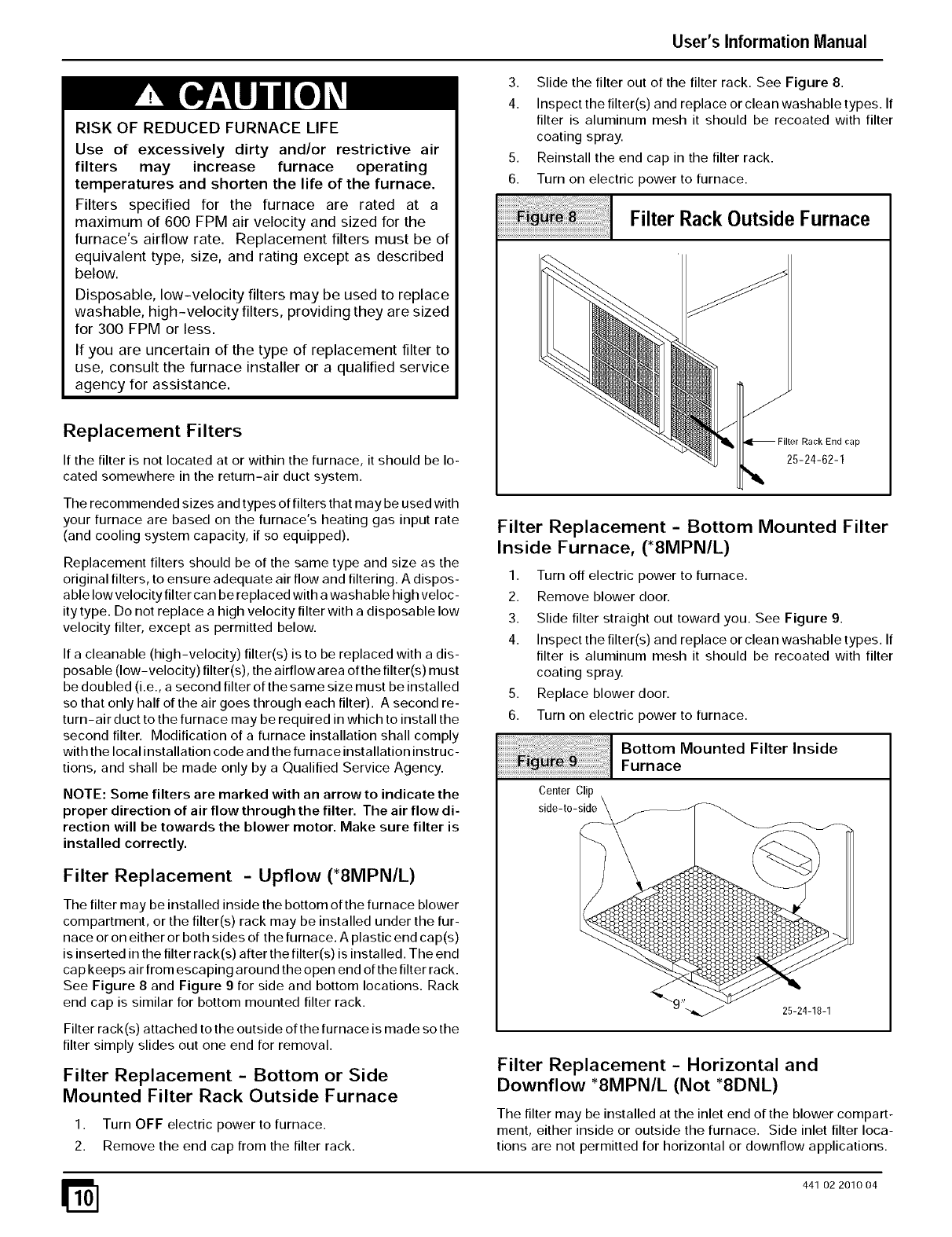
Filter Rack Outside Furnace
NOTE: Some filters are marked with an arrow to indicate the
proper direction of air flow through the filter. The air flow di-
rection will be towards the blower motor. Make sure filter is
installed correctly.
Filter Replacement - Upflow (*8MPN/L)
The filter may be installed inside the bottom of the furnace blower
compartment, or the filter(s) rack may be installed under the fur-
nace or on either or both sides of the furnace. A plastic end cap(s)
is inserted in the filter rack(s) after the filter(s) is installed. The end
ca p keeps air from esca ping around the open end of the filter rack.
See Figure 8 and Figure 9 for side and bottom locations. Rack
end cap is similar for bottom mounted filter rack.
Filter rack(s) attached to the outside of the furnace is made so the
filter simply slides out one end for removal.
End cap
25-24-62-1
Filter Replacement - Bottom or Side
Mounted Filter Rack Outside Furnace
1. Turn OFF electric power to furnace.
2. Remove the end cap from the filter rack.
Filter Replacement -Horizontal and
Downflow *8MPN/L (Not *8DNL)
The filter may be installed at the inlet end of the blower compart-
ment, either inside or outside the furnace. Side inlet filter loca-
tions are not permitted for horizontal or downflow applications.
441 02 2010 04
Center Clip
side-to-side
25-24-18-1
Filter Replacement -Bottom Mounted Filter
Inside Furnace, (*8MPN/L)
1. Turn off electric power to furnace.
2. Remove blower door.
3. Slide filter straight out toward you. See Figure 9.
4. Inspect the filter(s) and replace or clean washable types. If
filter is aluminum mesh it should be recoated with filter
coating spray
5. Replace blower door.
6. Turn on electric power to furnace.
1 Bottom Mounted Filter InsideFurnace
User's Information Manual
External Filter Rack
A plastic end cap is inserted in the filter rack after the filter is
installed. The end cap keeps air from escaping around the
open end of the filter rack. See Figure 8 for removal of filter.
Filter racks attached to the furnace are made so the filter simply
slides out one end for removal.
1. Turn OFF electric power to furnace.
2. Remove the end cap from the filter rack.
3. Slide the filter out of the filter rack.
4. Inspect the filter(s) and replace or clean washable types. If
filter is aluminum mesh it should be recoated with filter coat-
ing spray.
5. Reinstall the end cap in the filter rack.
6. Turn furnace on.
Internally Mounted Filter
1. Turn OFF power to furnace.
2. Remove blower door.
3. Slide filter straight out toward you. (See Figure 9.)
4. Inspect the filter(s) and replace or clean washable types. If
filter is aluminum mesh it should be recoated with filter coat-
ing spray.
5. Replace blower door
6. Turn on electric power to furnace.
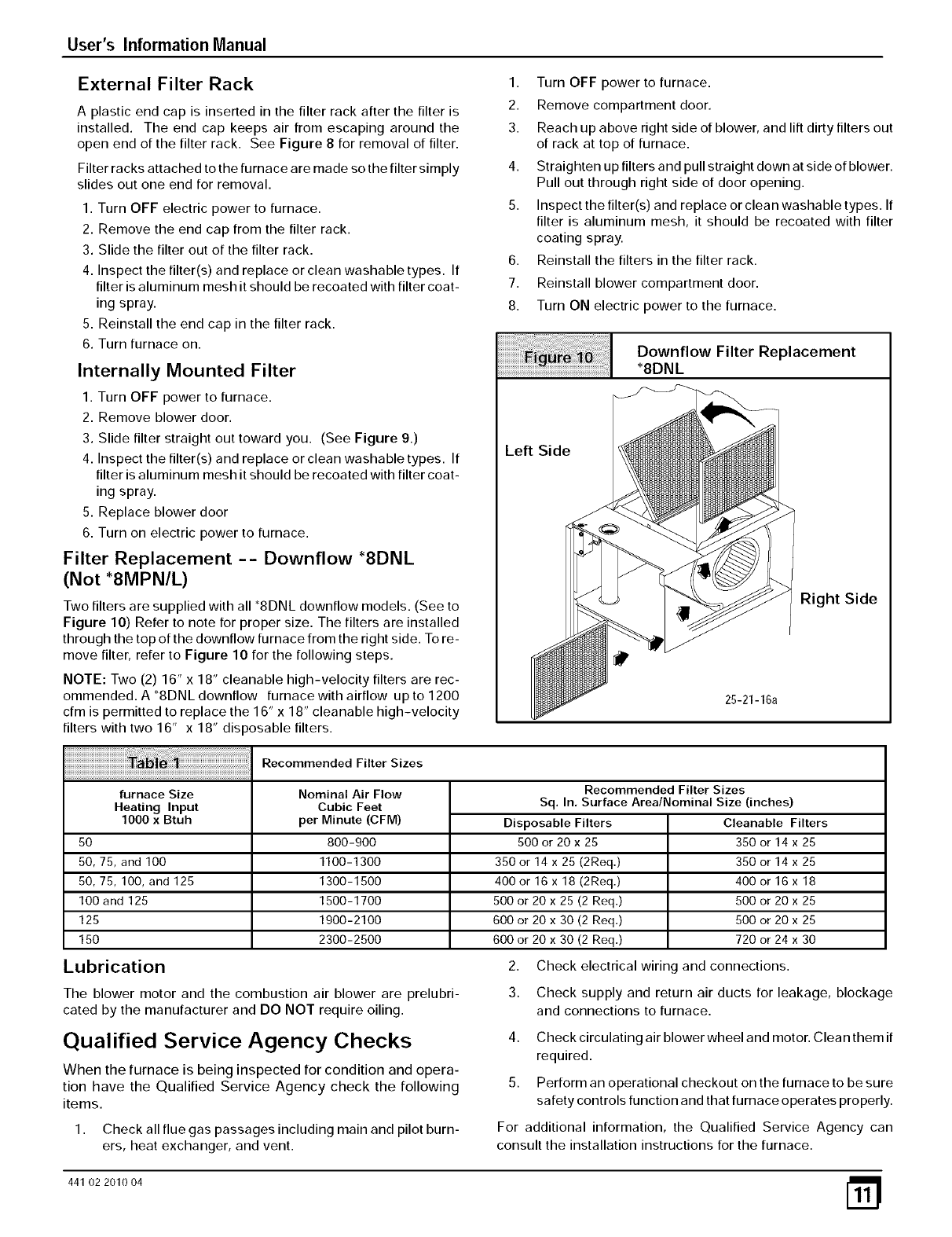
Filter Replacement -- Downflow _8DNL
(Not *8MPN/L)
Two filters are supplied with all '8DNL downflow models. (See to
Figure 10) Refer to note for proper size. The filters are installed
through the top of the downflow furnace from the right side. To re-
move filter, refer to Figure 10 for the following steps.
NOTE: Two (2) 16" x 18" cleanable high-velocity filters are rec-
ommended. A _8DNL downflow furnace with airflow up to 1200
cfm is permitted to replace the 16" x 18" cleanable high-velocity
filters with two 16" x 18" dis )osable filters.
Recommended Filter Sizes
furnace Size
Heating Input
1000 x Btuh
5O
50, 75, and 100
50,75,100, and125
100 and 125
125
150
Lubrication
Nominal Air Flow
Cubic Feet
per Minute (CFM)
800-900
1100-1300
1300-1500
1500-1700
1900-2100
2300-2500
1. Turn OFF power to furnace.
2. Remove compartment door.
3. Reach up above right side of blower, and lift dirty filters out
of rack at top of furnace.
4. Straighten up filters and pull straight down at side of blower.
Pull out through right side of door opening.
5. Inspect the filter(s) and replace or clean washable types. If
filter is aluminum mesh, it should be recoated with filter
coating spray.
6. Reinstall the filters in the filter rack.
7. Reinstall blower compartment door.
8. Turn ON electric power to the furnace.
Left Side
Right Side
Downflow Filter Replacement
*8DNL
Recommended Filter Sizes
Sq. In, Surface Area/Nominal Size (inches)
Disposable Filters
500 or 20 x 25
350 or 14 x 25 (2Req.)
400 or 16 x 18 (2Req.)
500 or 20 x 25 (2 Req.)
600 or 20 x 30 (2 Req.)
600 or 20 x 30 (2 Req.)
Cleanable Filters
350 or 14 x 25
350 or 14 x 25
400 or16x18
500 or 20 x 25
500 or 20 x 25
720 or 24 x 30
The blower motor and the combustion air blower are prelubri-
cated by the manufacturer and DO NOT require oiling.
Qualified Service Agency Checks
When the furnace is being inspected for condition and opera-
tion have the Qualified Service Agency check the following
items.
1.
2.
3.
4.
5.
Check all flue gas passages including main and pilot burn-
ers, heat exchanger, and vent.
Check electrical wiring and connections.
Check supply and return air ducts for leakage, blockage
and connections to furnace.
Check circulating air blower wheel and motor. Clean them if
required.
Perform an operational checkout on the furnace to be sure
safety controls function and that furnace operates properly.
For additional information, the Qualified Service Agency can
consult the installation instructions for the furnace.
441 02 201004
25-21-16a

User's Information Manual
441 02 2010 04
User's Information Manual
441 02 2010 04
User's Information Manual
441 02 2010 04
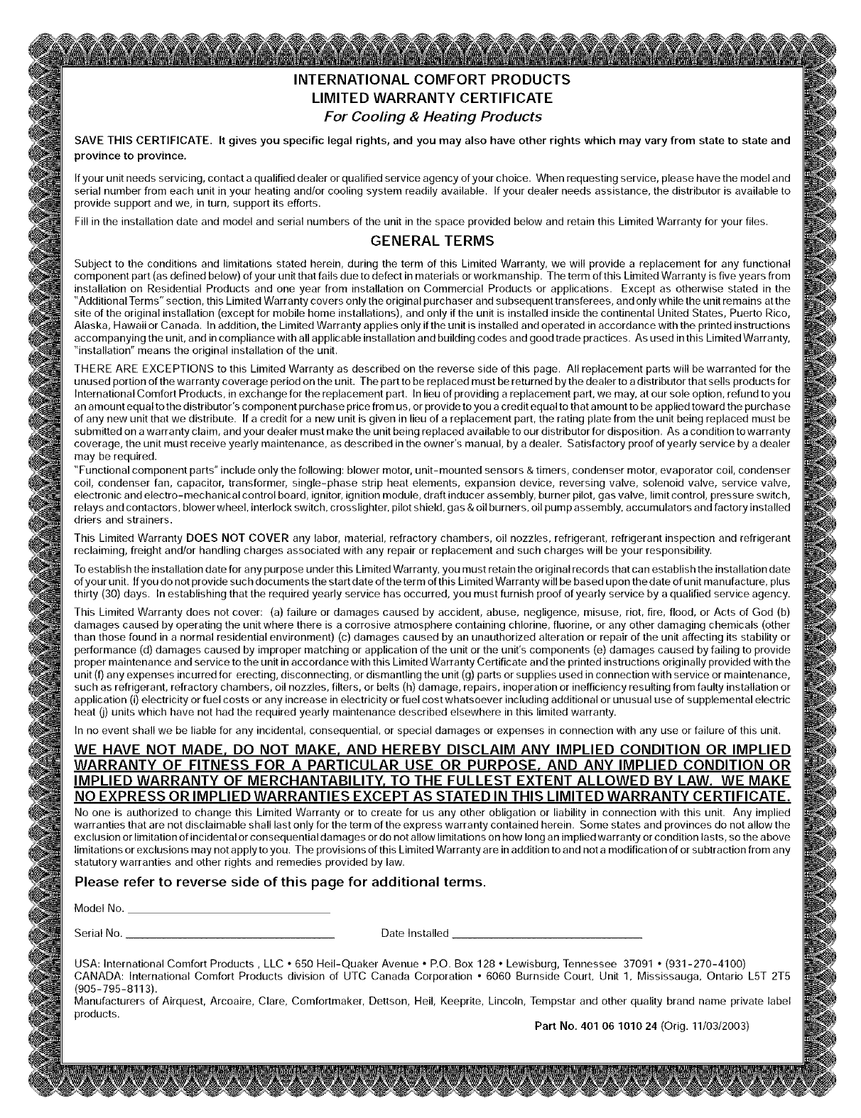
INTERNATIONAL COMFORT PRODUCTS
LIMITED WARRANTY CERTIFICATE
For Cooling & Heating Products
SAVE THIS CERTIFICATE, It gives you specific legal rights, and you may also have other rights which may vary from state to state and
province to province.
If your unit needs servicing, contact a qualified dealer or qualified service agency of your choice. When requesting service, please have the model and
serial number from each unit in your heating and/or cooling system readily available. If your dealer needs assistance, the distributor is available to
provide support and we, in turn, support its efforts.
Fill in the installation date and model and serial numbers of the unit in the space provided below and retain this Limited Warranty for your files.
GENERAL TERMS
Subject to the conditions and limitations stated herein, during the term of this Limited Warranty, we will provide a replacement for any functional
component part (as defined below) of your unit that fails due to defect in materials or workmanship. The term of this Limited Warranty is five years from
installation on Residential Products and one year from installation on Commercial Products or applications. Except as otherwise stated in the
"Additional Terms" section, this Limited Warranty covers only the original purchaser and subsequent transferees, and only while the unit remains at the
site of the original installation (except for mobile home installations), and only if the unit is installed inside the continental United States, Puerto Rico,
Alaska, Hawaii or Canada. In addition, the Limited Warranty applies only if the unit is installed and operated in accordance with the printed instructions
accompanying the unit, and in compliance with all applicable installation and building codes and good trade practices. As used in this Limited Warranty,
"installation" means the original installation of the unit.
THERE ARE EXCEPTIONS to this Limited Warranty as described on the reverse side of this page. All replacement parts will be warranted for the
unused portion of the warranty coverage period on the unit. The part to be replaced must be returned by the dealer to a distributor that sells products for
International Comfort Products, in exchange for the replacement part. In lieu of providing a replacement part, we may, at our sole option, refund to you
an amount equal to the distributor's component purchase price from us, or provide to you a credit equal to that amount to be applied toward the purchase
of any new unit that we distribute. If a credit for a new unit is given in lieu of a replacement part, the rating plate from the unit being replaced must be
submitted on a warranty claim, and your dealer must make the unit being replaced available to our distributor for disposition. As a condition to warranty
coverage, the unit must receive yearly maintenance, as described in the owner's manual, by a dealer. Satisfactory proof of yearly service by a dealer
may be required.
"Functional component parts" include only the following: blower motor, unit-mounted sensors & timers, condenser motor, evaporator coil, condenser
coil, condenser fan, capacitor, transformer, single-phase strip heat elements, expansion device, reversing valve, solenoid valve, service valve,
electronic and electro-mechanical control board, ignitor, ignition module, draft inducer assembly, burner pilot, gas valve, limit control, pressure switch,
relays and contactors, blower wheel, interlock switch, crosslighter, pilot shield, gas & oil burners, oil pure p assembly, accumulators and factory installed
driers and strainers.
This Limited Warranty DOES NOT COVER any labor, material, refractory chambers, oil nozzles, refrigerant, refrigerant inspection and refrigerant
reclaiming, freight and/or handling charges associated with any repair or replacement and such charges will be your responsibility.
To establish the installation date for any purpose under this Limited Warranty, you must retain the original records that ca n establish the installation date
ofyour unit. Ifyoudonot providesuchdocumentsthestartdateoftheterm ofthis Limited Warrantywillbe based upon thedate of unit manufacture, plus
thirty (30) days. In establishing that the required yearly service has occurred, you must furnish proof of yearly service by a qualified service agency.
This Limited Warranty does not cover: (a) failure or damages caused by accident, abuse, negligence, misuse, riot, fire, flood, or Acts of God (b)
damages caused by operating the unit where there is a corrosive atmosphere containing chlorine, fluorine, or any other damaging chemicals (other
than those found in a normal residential environment) (c) damages caused by an unauthorized alteration or repair of the unit affecting its stability or
performance (d) damages caused by improper matching or application of the unit or the unit's components (e) damages caused by failing to provide
proper maintenance and service to the unit in accordance with this Limited Warranty Certificate and the printed instructions originally provided with the
unit (f) any expenses incurred for erecting, disconnecting, or dismantling the unit (g) parts or supplies used in connection with service or maintenance,
such as refrigerant, refractory chambers, oil nozzles, filters, or belts (h) damage, repairs, inoperation or inefficiency resulting from faulty installation or
application (i) electricity or fuel costs or any increase in electricity or fuel cost whatsoever including additional or unusual use of supplemental electric
heat (i) units which have not had the required yearly maintenance described elsewhere in this limited warranty.
In no event shall we be liable for any incidental, consequential, or special damages or expenses in connection with any use or failure of this unit.
WE HAVE NOT MADE, DO NOT MAKE, AND HEREBY DISCLAIM ANY IMPLIED CONDITION OR IMPLIED
WARRANTY OF FITNESS FOR APARTICULAR USE OR PURPOSE, AND ANY IMPLIED CONDITION OR
IMPLIED WARRANTY OF MERCHANTABILITY, TO THE FULLEST EXTENT ALLOWED BY LAW. WE MAKE
NO EXPRESS OR IMPLIED WARRANTIES EXCEPT AS STATED IN THIS LIMITED WARRANTY CERTIFICATE.
No one is authorized to change this Limited Warranty or to create for us any other obligation or liability in connection with this unit. Any implied
warranties that are not disclaimable shall last only for the term of the express warranty contained herein. Some states and provinces do not allow the
exclusion or limitation of incidental or consequential damages or do not allow limitations on how long an implied warranty or condition lasts, so the a bore
limitations or exclusions may not apply to you. The provisions of this Limited Warranty are in addition to and not a modification of or subtraction from any
statutory warranties and other rights and remedies provided by law.
Please refer to reverse side of this page for additional terms.
Model No.
Serial No. Date Installed
USA: International Comfort Products, LLC •650 Hell-Quaker Avenue •nO. Box 128 •Lewisburg, Tennessee 37091 •(931-270-4100)
CANADA: International Comfort Products division of UTC Canada Corporation •6060 Burnside Court, Unit 1, Mississauga, Ontario L5T 2T5
(905-795-8113).
Manufacturers of Airquest, Arcoaire, Clare, Comfortmaker, Dettson, Hell, Keeprite, Lincoln, Tempstar and other quality brand name private label
products.
Part No, 401 06 1010 24 (Orig. 11/03/2003)
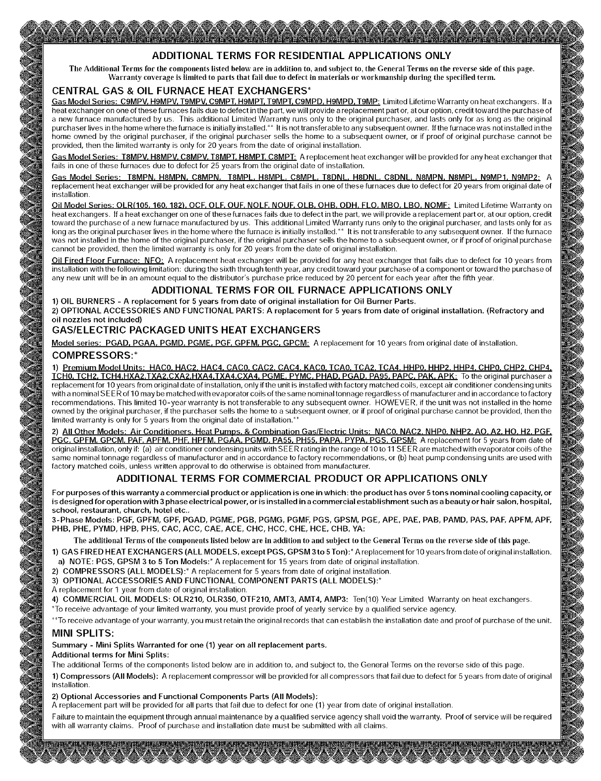
ADDITIONAL TERMS FOR RESIDENTIAL APPLICATIONS ONLY
Tile Additional Terms for tile components listed below are in addition to, and subject to, the General Terms on tile reverse side of this page.
Warranty coverage is limited to parts that fail due to defect in materials or workmanship daring the specified term.
CENTRAL GAS & OIL FURNACE HEAT EXCHANGERS*
Gas Model Series: C9MPV, H9MPV, T9MPV, C9MPT, H9MPT, T9MPT, C9MPD, H9MPD, T9MP: Limited Lifetime Warranty on heat exchangers. If a
heat exchanger on one of these furnaces fails due to defect in the part, we will provide a replacement part or, at our option, credit toward the purchase of
a new furnace manufactured by us. This additional Limited Warranty runs only to the original purchaser, and lasts only for as long as the original
purchaser lives in the home where the furnace is initially installed.** It is not transferable to any subsequent owner. If the furnace was not installed in the
home owned by the original purchaser, if the original purchaser sells the home to a subsequent owner, or if proof of original purchase cannot be
provided, then the limited warranty is only for 20 years from the date of original installation.
Gas Model Series: T8MPV. H8MPV. C8MPV. T8MPT. H8MPT. C8MPT: A replacement heat exchanger will be provided for any heat exchanger that
fails in one of these furnaces due to defect for 25 years from the original date of installation.
Gas Model Series: T8MPN. H8MPN. C8MPN. T8MPL. H8MPL. C8MPL. T8DNL. H8DNL. C8DNL N8MPN. N8MPL. N9MP1. N9MP2: A
replacement heat exchanger will be provided for any heat exchanger that fails in one of these furnaces due to defect for 20 years from original date of
installation.
Oil Model Series: OLR(105. 160. 182L OCF. OLF. OUF. NOLF. NOUE OLB. OHB. ODH. FLO. MBO. LBO. NOMF: Limited Lifetime Warranty on
heat exchangers. If a heat exc ha nger on one of these furnaces fails due to defect in the part, we will provide a replacement part or, at our option, credit
toward the purchase of a new furnace manufactured by us. This additional Limited Warranty runs only to the original purchaser, and lasts only for as
Iongastheoriginalpurchaserlivesinthehomewherethefurnaceisinitiallyinstalled.** Iris nottransferabletoanysubsequentowner. If the furnace
was not installed in the home of the original purchaser, if the original purchaser sells the home to a subsequent owner, or if proof of original purchase
cannot be provided, then the limited warranty is only for 20 years from the date of original installation.
Oil Fired Floor Furnace: NFO: A replacement heat exchanger will be provided for any heat exchanger that fails doe to defect for 10 years from
installation with the following limitation: during the sixth through tenth year, any credit toward your purchase of a component or toward the purchase of
any new unit will be in an amount equal to the distributor's purchase price reduced by 20 percent for each year after the fifth year.
ADDITIONAL TERMS FOR OIL FURNACE APPLICATIONS ONLY
1) OIL BURNERS - A replacement for 5 years from date of original installation for Oil Burner Parts.
2) OPTIONAL ACCESSORIES AND FUNCTIONAL PARTS: A replacement for 5 years from date of original installation. (Refractory and
oil nozzles not included)
GAS/ELECTRIC PACKAGED UNITS HEAT EXCHANGERS
Model series: PGAD, PGAA, PGMD, PGME, PGF, GPFM, PGC, GPCM: A replacement for 10 years from original date of installation.
COMPRESSORS:*
1) Premium Model Units: HAC0. HAC2. HAC4. CAC0. CAC2. CAC4. KAC0. TCA0. TCA2. TCA4. HHP0. HHP2. HHP4. CliP0. CliP2. CliP4.
TCH0. TCH2. TCH4.HXA2.TXA2.CXA2.HXA4.TXA4.CXA4. PGME. PYMC. PHAD. PGAD. PA95. PAPC. PAK. APK: To the original purchaser a
replacement for 10 years from original date of installation, only if the unit is installed with factory matched coils, except air conditioner condensing units
with a nominal S E E R of 10 may be matched with evaporator coils of the same nominal tonnage regardless of manufacturer and in accordance to factory
recommendations. This limited 10-year warranty is not transferable to any subsequent owner. HOWEVE R, if the unit was not installed in the home
owned by the original purchaser, if the purchaser sells the home to a subsequent owner, or if proof of original purchase cannot be provided, then the
limited warranty is only for 5 years from the original date of installation.**
2) All Other Models: Air Conditioners. Heat Pumns. & Combination Gas/Electric Units: NAC0. NAC2. NHP0. NHP2. AO. A2. HO. H2. PGF.
PGC. GPFM. GPCM. PAR APFM. PHF. HPFM. PGAA. PGMD. PA55. PH55. PAPA. PYPA. PGS. GPSM: A replacement for 5 years from date of
original installation, only if: (a) air conditioner condensing units with S E E R rating in the range of 10 to 11 S E E R are matched with evaporator coils of the
same nominal tonnage regardless of manufacturer and in accordance to factory recommendations, or (b) heat pump condensing units are used with
factory matched coils, unless written approval to do otherwise is obtained from manufacturer.
ADDITIONAL TERMS FOR COMMERCIAL PRODUCT OR APPLICATIONS ONLY
For purposes of this warranty a commercial product or application is one in which: the product has over 5 tons nominal cooling capacity, or
is designed for operation with 3 phase electrical power, or is installed in a commercial establi shment such as a beauty or hair salon, hospital,
school, restaurant, church, hotel etc.,
3-Phase Models: PGF, GPFM, GPF, PGAD, PGME, PGB, PGMG, PGMF, PGS, GPSM, PGE, APE, PAE, PAB, PAMD, PAS, PAF, APFM, APE
PHB, PHE, PYMD, HPB, PHS, CAC, ACC, CAE, ACE, CHC, HCC, CHE, HCE, CHB, YA:
Tile additional Terms of tire components listed below are in addition to and subject to tire General Terms on tire reverse side of this page.
1) GAS FIRED HEAT EXCHANGERS (ALL MODELS, except PGS, GPSM 3to 5Ton):* A replacement for 10 years from date of original installation.
a) NOTE: PGS, GPSM 3 to 5 Ton Models:* A replacement for 15 years from date of original installation.
2) COMPRESSORS (ALL MODELS):* A replacement for 5 years from date of original installation.
3) OPTIONAL ACCESSORIES AND FUNCTIONAL COMPONENT PARTS (ALL MODELS):*
A replacement for 1 year from date of original installation.
4) COMMERCIAL OIL MODELS: OLR210, OLR350, OTF210, AMT3, AMT4, AMP3: Ten(10) Year Limited Warranty on heat exchangers.
*To receive advantage of your limited warranty, you must provide proof of yearly service by a qualified service agency.
**To receive advantage of your warranty, you must retain the original records that can establish the installation date and proof of purchase of the unit.
MINI SPLITS:
Summary - Mini Splits Warranted for one (1) year on all replacement parts.
Additional terms for Mini Splits:
The additional Terms of the components listed below are in addition to, and subject to, the General Terms on the reverse side of this page.
1) Compressors (All Models): A replacement compressor will be provided for all compressors that fail due to defect for 5 years from date of original
installation.
2) Optional Accessories and Functional Components Parts (All Models):
A replacement part will be provided for all parts that fail due to defect for one (1) year from date of original installation.
Failure to maintain the equipment through annual maintenance by a qualified service agency shall void the warranty. Proof of service will be required
with all warranty claims. Proof of purchase and installation date must be submitted with all claims.
