ICP Furnace/Heater, Gas Manual L0502541
User Manual: ICP ICP Furnace/Heater, Gas Manual ICP Furnace/Heater, Gas Owner's Manual, ICP Furnace/Heater, Gas installation guides
Open the PDF directly: View PDF ![]() .
.
Page Count: 20

MULTI POSITION
WARM AIR
FURNACE
Save these instructions for future reference.
Printed in Canada
02/05/22 X40094 Rev. A
445 01 4094 00

PART 1
INSTALLATION
2) SAFE INSTALLATION REQUIREMENTS
1) SAFETY LABELLING AND SIGNAL WORDS
Installation or repairs made by unqualified persons
can result in hazards to you and others. Installation
MUST conform with codes or, in the absence of
local codes, with codes of the country having
jurisdiction.
The information contained in this manual is
intended for use by a qualified service technician
familiar with safety procedures and equipped with
the proper tools and test instruments.
Failure to carefully read and follow all instructions
in this manual can result in furnace malfunction,
property damage, personal injury and/or death.
1.1) Danger, Warning and Caution:
The signal words DANGER, WARNING and CAUTION are used to
identify levels of hazard seriousness. The signal word DANGER is
only used in product labels to signify an immediate hazard. The signal
words WARNING and CAUTION will be used on product labels and
throughout this manual and other manuals that may apply to the
product.
1.2) Signal Words:
DANGER - Immediate hazards which WILL result in death or serious
injury.
WARNING - Hazards or unsafe practices which COULD result in
death or injury.
CAUTION - Hazards or unsafe practices which COULD result in
personal injury or product or property damage.
1.3) Signal Words in Manuals:
The signal word WARNING is used throughout this manual in the
following manner:
The signal word CAUTION is used throughout this manual in the
following manner:
CAUTION
Fire hazard
The furnace must be installed in a level position,
never where it will slope to the front.
If the furnace were installed in that position, oil
could drain into the furnace vestibule and create a
fire hazard, instead of draining properly into the
combustion chamber.
NOTE: It is the personal responsibility and obligation of the customer
to contact a qualified installer to ensure that the installation is
adequate and conforms to governing codes and ordinances.
a. This furnace is NOT approved for installation in mobile homes,
trailers or recreation vehicles.
b. You must have a sufficient supply of fresh air for combustion and
ventilation to the area in which the furnace is located,
c, Do NOT use this furnace as a construction heater or to heat a
building that is under construction,
d. Use only the Type of fuel oil approved for this furnace (see
Rating Plate on unit). Overfiring wilt result in failure of heat
exchanger and cause dangerous operation.
e, Visually check all oil line joints for signs of wetness, which would
indicate a leak,
f, Connect furnace to the chimney,
g. The points in Part 2 "Operation" are vital to the proper and safe
operation of the heating system, Take the time to be sure they
are all done.
h. Follow the rules of the NFPA Pamphlet No.31 (for USA) and 13-
139 (for Canada) or local codes for locating and installing the oil
storage tank.
i. Follow a regular service and maintenance schedule for efficient
and safe operation.

j. Beforeservicing,allowfurnacetocool.Alwaysshutoffelectricity
andfueltofurnacewhenservicing.ThiswilIpreventelectrical
shockorburns.
k. Sealsupplyandreturnairducts.
I. TheventsystemMUSTbecheckedtodeterminethatitisthe
correcttypeandsize.
m. Installcorrectfiltertypeandsize.
n. UnitMUST be installed so electrical components are protected
from direct contact with water.
2.1) Safety Rules:
Your unit is built to provide many years of safe and dependable
service providing it is properly installed and maintained. However,
abuse and/or improper use can shorten the life of the unit and create
hazards for you, the owner.
The U.S. Consumer Product Safety Commission recommends
that users of oil-burning appliances install carbon monoxide
detectors. There can be various sources of carbon monoxide in
a building or dwelling. The sources could be gas-fired clothes
dryers, gas cooking stoves, water heaters, furnaces, gas-fired
fireplaces, wood fireplaces, and several other items. Carbon
monoxide can cause serious bodily injury and/or death.
Therefore, to help alert people dpotentially dangerous carbon
monoxide levels, you should have carbon monoxide detectors
listed by a nationally recognised agency (e.g. Underwriters
Laboratories or International Approval Services) installed and
maintained in the building or dwelling (see Note).
b. There can be numerous sources of fire or smoke in a building or
dwelling. Fire or smoke can cause serious bodily injury, death,
and/or property damage. Therefore, in order to alert people of
potentially dangerous fire or smoke, you should have fire and
smoke detectors listed by Underwriters Laboratories installed
and maintained in the building or dwelling (see Note below).
INOTE: The manufacturer of your furnace does not test any detectors
and makes no representations regarding any brand or type of
detector.
I CAUTION
Insure that the area around the combustion air intake
terminal is free of snow, ice and debris.
2.2) Freezing Temperature and Your
Structure:
Your unit is equipped with safety devices that may keep it from
operating if sensors detect abnormal conditions such as clogged
exhaust flues.
If the structure will be unattended during cold weather you should take
these precautions.
a. Turn off main water supply into the structure and drain the water
lines if possible. Open faucets in appropriate areas.
b. Have someone check the structure frequently during cold
weather to make sure it is warm enough to prevent pipes from
freezing. Suggest they call a qualified service agency, if
required.
2.3) Installation regulation:
All local and national code requirements governing the installation of
oil burning equipment, wiring and flue connections MUST be followed.
Some of the codes that may be applicable are:
CSA B139 INSTALLATION CODE FOR OIL
BURNING EQUIPMENT
NFPA31 INSTALLATION OF OIL BURNING
EQUIPMENT
ANSI/NFPA90B WARM AIR HEATING AND AIR
CONDITIONING SYSTEMS
ANSI/NFPA 70 NATIONAL ELECTRICAL CODE
CSA C22.2 No3 CANADIAN ELECTRICAL CODE
ANSI/NFPA 211 CHIMNEYS, FIREPLACES, VENTS
AND SOLID FUEL BURNING
APPLIANCES
Only the latest issues of the above codes should be used.
3) LOCATING THE FURNACE
CAUTION
Check carefully your furnace upon delivery for any
evidence of damage that may have occurred during
shipping and handling. Any claims for damages or lost
parts must be made with the Transport Company.
Freeze warning.
Turn off water system.
If your unit remains shut offduring cold weather the
water pipes could freeze and burst, resulting in
serious water damage.

As this unit may be installed as an upflow, counterflow or horizontal
furnace (right or left), it may be located in a basement, on the same
level as the area to be heated, suspended, or in a crawlspace. In any
case, the unit should always be installed level.
In a basement, or when installed on the floor (as in a crawlspace), it
is recommended that the unit be installed on a concrete pad that is
1" to 2" thick.
When installed in the counterflow position, this furnace must not be
installed on combustible flooring, unless the approved sub-base is
used (Model # DFB-101). The flue pipe must exit the cabinet
through one of the panel opening, then extended up the side of the
furnace. Care must be taken to insure that the clearances from the
flue pipe to combustible construction are maintained.
Also, it is recommend to use the flue pipe guard kit
(Model # FPG-101 or # FPG102) to insure that a fire hazard
condition does not exist.
When installed in a horizontal position, the furnace may be
suspended by using an angle iron frame, as long as the total weight
of both the furnace and the frame are allowed for in the support
calculations. (Other methods of suspending are acceptable.) When
installed in the Horizontal Position, this furnace must not be installed
on combustible flooring, unless the approved sub-base is used
(Model # HFB-101).
This furnace is approved for reduced clearances to combustible
construction. Therefore, it may be installed in a closet or similar
enclosure.
The required minimum clearances for this furnace in all
positions are specified in tables # 3.2 and 3.3.
The furnace should be located as close as possible to the chimney
or vent in order to keep vent connections shorts and direct. The
furnace should also be located as near as possible to the center of
the air distribution system.
ICAUTION
Do NOT operate furnace in a corrosive atmosphere
containing chlorine, fluorine or any other damaging
chemicals. Refer to Part 1, section 5.2.
Electrical shock hazard.
This furnace is not watertight and is not designed
for outdoor installation. This furnace shall be
installed in such a manner as to protect the
electrical components from water.
Outdoor installation would lead to a hazardous
electrical condition and to premature furnace
failure, property damage, bodily injury or death.
4) VENTING
Poison carbon monoxide gas, fire and explosion
hazard.
Read and follow all instructions in this section.
Failure to properly vent this furnace can result in
property damage, personal injury and/or death.
CAUTION
When the furnace (chimney installation) is co-vented
with other combustion appliances such as a water
heater, the allowable venting materials (i.e. L-Vent etc.)
for use with those appliances should also be
investigated.
Poison carbon monoxide gas hazard
Never install a hand operated damper in the vent
pipe. However, any Underwriters Laboratories
listed electrically operated automatic type vent
damper may be installed if desired. Be sure to
follow instructions provided with vent damper.
Read and follow all instructions in this section.
Failure to properly vent this furnace or other
appliances can result in property damage, personal
injury and/or death.
Venting of the furnace should be to the outside and in accordance
with local codes or requirements dthe local utility.
OIL FIRED APPLIANCES SHALL BE CONNECTED TO FLUES
HAVING SUFFICIENT DRAFT AT ALL TIMES TO ENSURE SAFE
AND PROPER OPERATION OF APPLIANCE.
For additional venting information refer to ANSl/NFPA 211 Chimney,
Fireplaces, Vents and Solid Fuel Burning Appliances and/or CSA
B 139 Installation Code.
This furnace is certified for use with Type '%" vent (maximum flue
gas temperature 575°F). The flue pipe clearance knockout in the
front top or side panel should be removed. Install the flue elbow so
that it exits the furnace cabinet through that opening.
Pre-instatlation vent system inspection:
Before this furnace is installed, it is highly recommended that any
existing vent system be completely inspected.
For any chimney or vent, this should include the following:
a. Inspection for any deterioration in the chimney or vent. If
deterioration is discovered, the chimney must be repaired or
the vent must be replaced.

b. Inspection to ascertain that the vent system is clears and free
of obstructions. Any blockage must be cleared before installing
this furnace.
¢. Clearing the chimney or vent if previously used for venting a
solid fuel burning appliance or fireplace.
d. Confirming that all unused chimney or vent connections are
properly sealed.
e. Verification that the chimney is properly lined and sized per the
applicable codes, (Refer to list of codes on page 3.)
Masonry Chimney:
This furnace can be vented into an existing masonry chimney. This
furnace must not be vented into a chimney servicing a solid fuel-
burning appliance. Before venting this furnace into a chimney, the
chimney must be checked for deterioration and repaired if
necessary. The chimney must be properly lined and sized per local
or national codes.
If the furnace is vented into a common chimney, the chimney must
be of sufficient area to accommodate the total flue products of all
appliances vented into the chimney.
The following requirements are provided for a safe venting system:
a. Ensure that the chimney flue is clear of any dirt or debris.
b. Ensure that the chimney is not servicing an open fireplace.
C. Never reduce the pipe size below the outlet size of the furnace.
d. All pipes should be supported using the proper clamps and/or
straps. These supports should be at least every four (4) feet.
e. All horizontal runs of pipe should have at least a 1/4" per foot of
upward slope.
f. All runs dpipe be as short as possible with as few turns as
possible.
g. Seams should be tightly joined and checked for leaks.
h. The flue pipe must not extend into the chimney but be flush
with the inside wall.
i. The chimney must extend three (3) feet above the highest point
where it passes through a roof of a building and at least two (2)
feet higher than any portion of a building within a horizontal
distance of ten (10) feet. It shall also be extended at lest five
(5) feet above the highest connected equipment flue collar.
j. Check local codes for any variance.
Factory Built Chimneys:
May use listed factory built chimneys. Refer to chimney
manufacturer's instructions for proper installation.
4.1) BAROMETRIC DRART CONTROL
The barometric draft control shipped with furnace MUST be used with
furnace to ensure proper operation. Instructions for installing control
are packed with control.
5) AIR FOR COMBUSTION
Poison carbon monoxide gas hazard.
Comply with ANSI/NFPA (in U.S.) or CSA (in
Canada) standard for the installation of Oil Burning
Equipment and applicable provision of local
building codes to provide combustion and
ventilation air.
Failure to provide adequate combustion and
ventilation air can result in personal injury and/or
death.
5.1) General:
Oil furnaces must have an adequate supply of combustion air. It is
common practice to assume that older homes have sufficient
infiltration to accommodate the combustion air requirement for the
furnace. However, home improvements such as new windows, doors,
and weather stripping have dramatically reduced the volume of air
leakage into the home.
When this furnace is installed in a closet or enclosure, two (2)
ventilation openings are required for combustion air. The openings
should be located about 6" from the top and the bottom of the
enclosure at the front of the furnace. Table # ! indicates the
minimum ventilation openings dimensions required.
TABLE # 1
Input Length Height
(MBTUH) (in,) (in,)
75- 105 16 8
120-155 20 10
Home air exhausters are common. Bathroom and kitchen fans, power
vented clothes dryers, and water heaters all tend to create a negative
pressure in the home. Should this occur, the chimney become less
and Iess effective and can easily downdraft.
Heat recovery ventilation (HRV) systems are gaining in popularity. The
HRVs are not designed to supply combustion air. If not properly
balanced, a serious negative pressure condition could develop in the
dwelling.
5.2) Contaminated Combustion Air :
Installation in certain areas or types of structures will increase the
exposure to chemicals or Halogens which may harm the furnace.
These instances will require that only outside air for combustion.
The following areas or types of structures may contain or have
exposure to the substances listed below. The installation must be
evaluated carefully as it may be necessary to provide outside air for
combustion.
a. Commercial building.
b. Building with indoor pools.
c. Furnaces installed near chemical storage areas.

Exposuretothesesubstances:
a. Permanentwavesolutionsforhair.
b. Chlorinatedwaxesandcleaners.
c. Chlorinebasedswimmingpoolchemicals.
d. Watersofteningchemicals.
e. De-icingsaltsorchemicals.
f. Carbontetrachloride.
g. Halogentyperefrigerants.
h. Cleaningsolvent(suchasperchloroethylene).
i. Printinginks,paintremovers,varnishes,etc..
j. Hydrochloricacid.
k. Solventcementsandglues.
I. Antistaticfabricsoftenersforclothesdryers.
m. Masoneryacidwashingmaterials.
6) OIL TANKS AND LINES
Check your local codes for the installation of the tank and accessories.
A manual shut-off valve and an oil filter shall follow sequence from
tank to burner. Be sure that the oil line is clean before connecting to
the burner. The oil Iine should be protected to eliminate any possible
damage. Installations having the fuel oil tank below the burner level
must employ a two pipe fuel supply system with an appropriate fuel
pump (more than 8' lift use 2 stage pump and more than 16' an
auxiliary pump).
Follow the pump instructions to determine the size of tubing you need
in relation of the lift, or the horizontal distance. At the beginning of
each heating season or each year, verify the complete oil distribution
system for oil leak.
At the beginning of each heating season or each year, verify the
complete oil distribution system for oil leak.
7) BURNER INSTALLATION
I IMPORTANT: Burner must always be installed in the
upright position with the ignition control on top.
Mounting the burner:
a.
b.
The warm air furnace burner mounting plate has a four bolts
configuration.
Position the mounting gasket between the mounting flange and
the appliance burner mounting plate. Line up the holes in the
mounting flange with the studs on the appliance mounting plate
and securely bolt in place.
After the burner is mounted:
a. Remove drawer assembly or air tube combination
b. Install nozzle (see specifications)
c. Confirm electrode settings
d. Make the electrical connections
e. Complete oil line connections
a. Set your voltmeter to line voltage.
b. Place one prong on your grounded electric entry box and one
prong on the black wire.
c. Read the voltage.
d. If the voltage is zero, check the white wire. If Iine voltage shows.
Reverse the 115-volt leads entering the furnace junction box.
FIGURE # 1
BLACK
V C A
o o
BLACK
RED
\
Nozzles:
The burners are provided with the highest capacity USGPH nozzle
installed. If another size nozzle, or replacement nozzle is required, use
the nozzle spray angle, type and manufacturer recommended in Table
#3. Note that all nozzle-marked sizes are based on a pump pressure
of 100 psi.
Always select nozzle sizes by working back from the actual desired
flow rate at operating pressure, and not by the nozzle marking.
Air and turbulator settings:
Before starting the burner for the first time, adjust the air and turbulator
settings to those listed in the Table #3. Once the burner becomes
operational, final adjustment will be necessary.
Fuel supply system:
Fuel Specifications
I NOTE: Use No.1 or No.2 Heating Oil (ASTM D396) or in Canada, useNo.! or No.2 Furnace Oil.
Before starting the burner be sure the fuel tank is adequately filled with
clean oil.
I CAUTION
Do not turn on the burner until you have checked the
polarity
Checking the polarity:
The oil burners used on the furnaces have solid state control systems
which makes them sensitive to the proper connections of the hot and
neutral power lines. The controls will be damaged if the two lines are
reversed.

Fire and explosion hazard.
Use only approved heating type oil in this furnace.
DO NOT USE waste oil, used motor oil, gasoline or
kerosene.
Use of these will result in death, personal injury
and/or property damage.
INOTE: You may notice a slight odor the first time your furnace is
operated. This will soon disappear. It is only the oil used on the parts
during manufacturing.
8) INSTALLING ACCESSORIES
NOTE: THE BACK SHOULD NOT BE CUT OUT FOR
RETURN AIR
Provision is also made on this furnace for a bottom return air duct.
Knockouts are provided on the floor of the furnace to facilitate the
cut out requirement to assembly dair filter rack and return
ductwork. (We recommend the use of this opening for horizontal
installations).
When furnace supply ducts carry air outside furnace area, seal return
air duct to furnace casing and terminate duct outside furnace space.
Install air conditioning cooling coil (evaporator) on downstream (in the
supply air plenum) or furnace.
If separate evaporator and blower unit is used, install good sealing
dampers for air flow control. Cold air from the evaporator coil going
through the furnace could cause condensation and shorten furnace
life.
I CAUTION
Dampers (purchased locally) MUST be automatic.
Electrical shock hazard.
Turn OFF electric power at fuse box or service
panel before making any electrical connections and
ensure a proper ground connection is made before
connecting line voltage.
Failure to do so could result in property damage,
bodily injury or death.
8.1) Air conditioning:
An air conditioning coil may be installed on the _side only.
Also, a minimum clearance must be allowed between the bottom of
the coil drain pan, and the top of the heat exchanger according to the
coil manufacturer instruction. Wire the thermostat and condensing unit
contactor as indicated in the wiring diagram (figures # 4 and # 4.! ).
8.2) Ductwork and Filter:
Installation:
Design and install air distribution system to comply with Air
Conditioning Contractors of America manuals or other approved
methods that conform to local codes and good trade practices.
Knockouts are provided on both sides of the furnace to cut the
required size opening for the installation of the return ductwork. This
can be done on either the right or the left side of the furnace. See
Figure # 3 and 3.1 for location and dimensions.
Poison carbon monoxide gas hazard.
Do NOT draw return air from inside a closet or
utility room. Return air duct MUST be sealed to
furnace casing.
Failure to properly seal duct can result in death,
personal injury and/or property damage.
Poison carbon monoxide gas hazard.
Install evaporator coil on the supply side of the
furnace ducting.
Evaporator coil installed in return side ducting can
cause condensation to form inside heat exchanger
resulting in heat exchanger failure. This could
result in death, personal injury and/or property
damage.

PART 2
OPERATION
1) SEQUENCE OF OPERATION
1.1) Sequence of operation - Beckett AFG:
1. Normally open contact (T-T) on primary relay closed when
thermostat calls for heat.
2. The motor starts and spark is established. The pump pressure
builds and the poppet valve opens admitting fuel to the nozzle.
Pressure builds and poppet valve opens, allowing oil to flow
through nozzle.
3. Spark ignites oil droplets.
4. Cad cell senses flame and burner continues to fire.
5. After 60 sec., the fan control starts the circulating air blower and
electronic air cleaner.
6. The circulating air blower and burner motor remain on until the
thermostat is satisfied. The ignition transformer continues to
spark.
7. Thermostat is satisfied.
8. Primary relay contacts open and the burner fan motor shuts
down. The ignition transformer ceases sparking.
9. Depend on the delay of setting of the fan control, the circulating
air blower stop after 60, 90, !20 or 150 seconds. (See part 2,
section 2.4).
2) CHECKS AND ADJUSTMENTS
2.1) General:
During initial start-up and subsequent yearly maintenance calls, the
furnace must be thoroughly tested.
IMPORTANT
The burner must be put in operation for at least 10
minutes before any test readings are taken. For new
installations, set up the burner to the settings (see table
# 3), before firing. These are rough adjustments but
they will ensure that the burner will start and run smoke-
free in advance of the fine adjustments being made.
Open the oil bleed port screw and start the burner. Allow the oil to
flush into a portable container for at least 10 seconds. Slowly close the
bleed screw - the oil should flow absolutely free of white streaks or
bubbles to indicate that no air is being drawn into the suction side of
the oil piping and pump. Tighten the bleed screw and the burner wilI
fire. Adjust the oil pressure as indicated in Table # 3.
2.2)
1.
2.
3.
4.
Restart if Burner Should Stop:
Set thermostat lower than the room temperature.
Press the reset button on the burner primary control (relay).
Set thermostat higher than the room temperature.
If the burner motor does not start or ignition fails, turn off the
disconnect switch and CALL YOUR SERVICEMAN
CAUTION
Do not attempt to start the burner when excess oil has
accumulated, when the furnace is full of vapour, or
when the combustion chamber is very hot.
2.3) Perform the smoke /CO2 test:
1.
2.
Pierce a test hole in the smoke pipe near the furnace breech.
Insert the smoke test instrument probe into the open hole.
Starting with a zero smoke reading, gradually reduce the burner
air setting until just a trace (#1 on Bacharach Scale) of smoke
results.
3. Take a CO2 sample at the same test location where the smoke
sample was taken. Note the CO2 reading associated with the #!
smoke condition.
4.
5.
Adjust the burner air setting to obtain a CO2 reading !% lower
than the reading associated with the #1 smoke.
This method of adjusting the CO2 will allow adequate excess air
to ensure that the burner will burn clean for the entire heating
season.

2.4) FAN ADJUSTMENT CHECK
This furnace is equipped with a 4 speed direct drive motor to deliver
a temperature rise within the range specified on the rating plate,
between the return and supply pressure at the external duct static
pressure noted on the rating label.
Adjust the fan speed ACCORDING TO THE OIL INPUT SELECTED
so that the temperature rise is within the rise specified on the rating
plate (see table # 3). Consult the wiring diagram for speed changes
on the direct drive motor.
To adjust fan OFF time, the DIP switches on the control board
adjusted to obtain the desired timing (See figure # 2).
FIGURE # 2
Delay off setting
60 Sec. 90 Sec. 120 Sec. 150 Sec.
DIP switchs
DNS-0378 Rev. A
Remove the restriction and the burner should come back on in a few
minutes.
For year round air conditioning:
The furnace is designed for use in conjunction with cooling
equipment to provide year round air conditioning. The blower has
been sized for both heating and cooling, however, the fan motor
speed may need to be changed to obtain the necessary cooling air
flow.
Heating:
The blower speed is factory set to deliver the required airflow at
normal duct static pressure.
Cooling:
The blower speed may be adjusted in the field to deliver the required
airflow, for cooling application, as outlined in table # 3
Constant Blower Switch:
This furnace is equipped with a constant low speed blower option.
Whenever the room thermostat is not calling for heating or cooling,
the blower will run on low speed in order to provide air circulation. If
this constant blower option is not desired, the rocker switch on the
side of the control box can be used to 'turn off" the constant speed.
2.5) Vent temperature test:
1. Place a thermometer in the test hole located in the breech pipe.
2. The vent temperature should be between 400 and 575°F. If
not, check for improper air temperature rise, pump pressure,
nozzle size, or for a badly sooted heat exchanger.
2.6) Limit control check
After the furnace has been in operation for at least 15 minutes,
restrict the return air supply by blocking the filters or closing the
return registers and allow the furnace to shut down on high limit.
The burner will shut OFF and the main blower should continue to
run.
PART 3
MAINTENANCE
1) GENERAL
Preventive Maintenance:
"Preventive maintenance" is the best way to avoid unnecessary
expense and inconvenience, Have your heating system and
burner inspected at regular intervals by a qualified service man.
After inspection, a complete combustion test must be performed after
each annual service of the unit to maintain optimum performance and
reliability.
Electrical shock hazard.
Turn OFF power to furnace before any disassembly
or servicing.
Failure to do so can result in property damage,
bodily injury and/or death.
10

Do not tamper with the unit or controls. Call your service
technician,
Before calling for service, check the following.
a. Check oil tank gauge and check if the oil tank valve is open.
b. Check fuse or circuit breaker.
c. Check if shut-off switch is 'ON".
d. Reset thermostat above room temperature.
e. If ignition does not occur turn off the disconnect switch and call
your qualified service technician.
When ordering replacement parts, specify the complete furnace
model number and serial number.
1.1) Heat exchanger cleaning:
Ordinarily, it is not necessary to clean the heat exchanger or flue pipe
every year, but it is advisable to have your oil burner serviceman
check the unit before each heating season to determine whether
cleaning or replacement of parts is necessary.
If cleaning is necessary, the following steps should be perfomed:
1. Turn 'OFF" atl utilities upstream of the furnace.
2. Disconnect the flue pipe.
3. Remove the flue cellar panel located in the front part of the warm
air furnace.
4. Remove the radiator baffles.
5. Disconnect the oil Iine and remove the oil burner from the
furnace.
6. Clean the secondary tubes, and the primary cylinder with stiff
brush and vacuum cleaner.
7. After cleaning, replace the radiator baffles, flue collar plate and
oil burner.
8. Readjust burner for proper operation.
Soot will have collected in the first sections of the heat exchangers
only if the burner was started after the combustion chamber was
flooded with fuel oil, or if the burner has been operating in a severely
fouled condition.
1.2) BLOWER REMOVAL
To remove the blower from the furnace:
1. Turn 'OFF" all utilities upstream of the furnace.
2. Remove the burner access door and blower door.
3. Remove the blower retaining screw (on the blower rails).
4. Remove cover from control box and disconnect the thermostat
and power wires from the board.
5. Slide the blower forward on the rails toward the front of the unit.
6. Reverse the above steps to reinstall the blower. (Refer to
wiring diagram figures # 4 a 4.1 of this instruction or the
diagram located on the inside of the blower door to properly
rewire the unit.)
CAUTION
Be sure the blower is adequately supported when
sliding out of the mounting rails, especially in the
horizontal, in order to prevent dropping the blower and
injuring yourself or damaging the blower!
To remove the blower from the furnace:
1. Turn 'OFF" all utilities upstream of the furnace.
2. Remove the burner access door and blower door.
3. Remove the blower retaining screw (on the blower partition
panel).
4. Remove cover from control box and disconnect the thermostat
and power wires from the board.
5. Slide the blower forward on the rails toward the front of the unit.
6. Reverse the above steps to reinstall the blower. (Refer to
wiring diagram figures # 4 a 4.1 of this instruction or the
diagram located on the inside of the blower door to properly
rewire the unit.)
1.3) Burner drawer assembly:
Remove the drawer assembly. Clean all foreign matter from the
retention head and electrodes. If a Beckett AFG burner has been
installed, the burner will have to be removed to check the retention
head and to check for proper "Z" dimension with the Beckett "T" gauge
supplied with every burner. Check for any sign of oil boiling out dthe
nozzle and caulking - the solenoid valve could be leaking (if
applicable).
1.4) Nozzle:
Replace the nozzle with the one specified in table # 3.
1.5) Oil filter:
Tank filter:
The tank filter should be replaced as required.
Secondary filter:
The 10 micron (or less) filter cartridges should be replaced annually.
1.6) Air filters:
Air filters are the disposable types. The disposable filters should be
replaced on at least an annual basis. Dusty conditions, presence of
animat hair etc. may demand much more frequent filter changes. Dirty
filters will impact furnace efficiency and increase oil consumption.
1.7) Motor lubrication:
Do not lubricate the oil burner motor or the direct drive blower motor
as they are permanently lubricated.
11

PART 4
INFORMATION
Model:
Date of installation of the furnace :
Service telephones - day :
Dealer's name and address :
Seria! number:
Night :
RESULT OF START-UP TEST
Nozzle:
Burner adjustments :
002 :
Gross stack temperature:
Ambiant temperature:
Chimney draft:
Overfire draft :
Test made by :
Primary air
Fine air
Draw Assembly
Smoke scale :
Pressure : psi
(Bacharach)
o F
o F
"C.E.
"C.E.
12
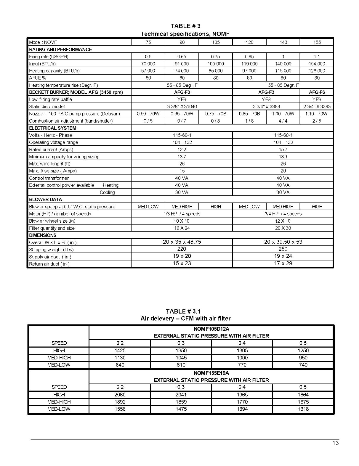
TABLE#3
Technicalspecifications, NOMF
Model : NOMF .1 75 J 90 [ 105 [ 120 ..[ 140 J155
RATING AND PERFORMANCE
Firing rate (USGPH) 0.5 0.65 0.75 0.85 1 1. !
Input (BTU/h) 70 000 91 OOO 105 0go 119 O00 140 0go 154 O00
Heating capacity (BTU/h) 57 00O 74 OOO 85 00O 97 OOO 1!5 0go 126 O00
AFUE % 80 80 80 80 80 80
Heating temperature rise (Degr. F) 55 - 85 Degr. F 55 - 85 Degr. F
BECKETr BURNER; MODEL AFG (3450 rpm) AFG-F3 AFG-F3 AFG-F6
Low firing rate baffle YES YES YES
Static disc, model 3 3/8" # 31646 2 3/4" # 3383 2 3/4" # 3383
Nozzle - 100 PSIG pump pressure (Detavan) 0.50 - 7OW 0.65 - 70W 0.75 - 7OB 0.85 - 70B I 1.00 - 7OW 1.!0 - 70W
Combustion air adjustment (band/shutter) O/5 0 /7 O/8 1 /8 / 4 /4 2 /8
ELECTRICAL SYSTEM
Volts - Hertz - Phase 115-60-1 115-60- !
Operating voltage range 104 - ! 32 104 - 132
Rated current (Amps) 12.2 15.7
Minimum ampacity for wiring sizing 13.7 18. !
Max. w ire Ienght (ft) 26 26
Max. fuse size (Amps) 15 20
Control transformer 40 VA 40 VA
External control pew er available Heating 40 VA 40 VA
Cooling 30 VA 30 VA
BLOWER DATA
Blow erspeepat0.5"W.C, static pressure MED-LOW I MED-HIGH I HIGH MED-LOW I MED-HIGH I HIGH
Motor (HP) /number of speeds 1/3 HP /4 speeds 3/4 HP /4 speeds
Blow er w heel size (in) 10 X !0 12 X 10
Filter quantity and size 16 X 24 20 X 30
DIMENSIONS
Overall W x L x H ( in ) 20 x 35 x 48.75 20 x 39.50 x 53
Shipping w eight (Lbs) 220 250
Supply air duct (in) 19 x 20 19 x 24
Return air duct ( in ) 15 x 23 17 x 29
TABLE # 3.1
Air delevery - CFM with air filter
NOM F105D12A
EXTERNAL STATIC PRESSURE WITH AIR FILTER
SPEED 0.2 0.3 0.4 0.5
HIGH 1425 1350 1305 1250
MED- HIGH 1130 1045 1000 950
MED-LOW 840 810 770 740
NOM F155E19A
EXTERNAL STATIC PRESSURE WITH AIR FILTER
SPEED 0.2 0.3 0.4 0.5
HIGH 2080 2041 1965 1864
MED- HIGH 1892 1859 1770 1675
MED-LOW 1556 1475 1394 1318
13

(n
8o
Be
,,ll_
BLUE
VERSION EN FRANCAIS INCLUS DANS MANUEL
D'INSTALLATION.
I
STANDARD HEAT /COOL WIRING DIAGRAM
WITH ST9103 ELECTRONIC FAN TIMER
OIL INPUT : 0.75 USGPH
COOLING CAPACITY ; 3 TONS MAX
Jumper : USE JUMPER ONLY WHEN THE COOLING AND
HEATING SPEEDS ARE SAME
FOR HUMIDIFIER AND EAC, REMOVE THE DUMMY TERMINAL MARKED HUM
FOR HUMIDIFIER OR EAC FOR ELECTRONIC AIR CLEANER
L° FIoAPAc, oR
ML _z
MH _L
HI
J
c
BLACK
BLUE
RED
OIL INPU
COOLINO : 2 1/2
to 3 TONS
OIL INPUT : 0.50 USGPH
COOLING CAPACITY : 2 TONS
115 VAC I_/60HZ pOWER SUPPLY
(FUSEO DISCONNECT ON HOT LEO]
GND ,llll<_ o N_
ED MOT LEAE _> ON
]6_1 _ CN6 2 CN6 4
l LIMIT
°b
UNUSED MOT LEAD>> "_J_BLFoCLwE LAqqON
Q.
3
"11
.,,&
r,a ,1_
tD
o"
c
tD

co
cu
I BLACK
BLACK
TRA_
R99GO01
: 3 BT91 (
CAPACITOR
LO Oz
ML
MH
HI
c
BLACK
BLUE
RED
VERSION EN FRANCAIS INCLUS BANS MANUEL
D'INSTALLATION.
,lll_ GND
LI (H)
L2 (N) 120 VAC POWER SUPPLY
120
CAD CELLI
STANDARD HEAT /COOL WIRING DIAGRAM
WITH ST9105 ELECTRONIC FAN TIMER
OIL INPUT : 0.85 USGPH
COOLING CAPACITY ; 4 TONS MAX
* Jumper : USE JUMPER ONLY WHEN THE COOLING AND HEATING
SPEEDS ARE SAME
FOR HUMIDIFIER AND EAC, REMOVE THE DUMMY TERMINAL MARKED HUM
FOR HUMIDIFIER OR EAC ELECTRONIC AIR CLEANER
I CAPAC'TOR
LOMNN,MLc
1
BLUE
RED
OIL INPUT : 1,00 USGPH
COOLINO CAPACITY : 4 to 5
115 VAC 1_' 60HZI pOICI_R SUPPLY
(FUSED DISCONNECT ON HOT LFG]
8 2
LIMIT(S) ___
CN6 8_CN6 5
TONS MAX
F
<
5Oz
LO _ <
OL
ML _,
_+
MH
_ WHITE
L BLACK
BLUE
CAPACITOR
OIL INPUT "1.10 USGPH
COOLING CAPACITY : 5 TONS
UNUSED M O Sl LEAD>> _m_ ON
COOL L_
*Jumper [__@
LEAD IRCULAllON
UNUSED MOT >_ x"_B LRoCwUL_
im
a
t-

DNS-0832 Rev A
7
I
I o
I
I
,I
FIGURE # 3
Model: NOMF105D12A
32O
I
J
35
1663
LOCATION
SIDE
BACK
TOP
BOTTOM
FLUE PIPE
FRONT
TABLE # 3.2
Minimum clearances - combustion materials (in), MODEL: NOMF105D12A
APPLICATION
FURN ACE
SUPPLY PLENUM WITHIN 6 FT OF FURNACE
FURN ACE
FURNACE OR PLENUM
HORIZONTAL WARM AIR DUCT WITHING 6 FT OF FURNACE
FURNACE (**COMBUSTIBLE FLOOR WITH THE SUBBASE)
HORIZONTALLY OR BELOW FLUE PIPE
VERTICALLY ABOVE FLUE PIPE
FURN ACE
UPFLOW
0
1
0
2
2
0
4
9
8
DOWNFLOW
2
2
1
2
2
**0
4
9
8
HORIZONTAL
2
1
0
2
3
**0
4
9
24
16

DNS-0833 R@v. A
FIGURE # 3.1
Model: NOMF155E19A
1_oo
2900 _=_1259--
TCPKN0CK OUT
FOR6_ DIA FLUE
2_00
5&00
I
--j
_F
'#_J
l
01LINLET
_(BOTH SIDE)
laD_
1_.75 |
--19.00--
LOCATION
SIDE
BACK
TOP
BOTTOM
FLUE PIPE
FRONT
TABLEAU # 3.3
Minimum clearances - combustion materials (in), MODEL: NOMF155E19A
APPLICATION
FURNAC E
SUPPLY PLENUM WITHIN 6 FT OF FURNACE
FURNAC E
FURNACE OR PLENUM
HORIZONTAL WARM AIR DUCT WITHING 6 FT OF FURNACE
FURNACE (**COMBUSTIBLE FLOOR WITH THE SUBBASE)
HORIZONTALLY OR BELOW FLUE PIPE
VERTICALLY ABOVE FLUE PIPE
FURNAC E
UPFLOW
1
1
0
2
2
0
4
9
8
DOWNFLOW
2
2
1
2
2
**0
4
9
8
HORIZONTAL
2
1
0
2
3
**0
4
9
24
17


ModUle : NOMF105D12A
PARTS LIST
I=]=_._"_e,,];.41M/ [e] _ _[I LV_l:!--;.i [.e,[e]Lv_ILv_I--_IEr_
Heat exchanger B01667
2 Back panel ass'y B01728 INCLUDES PANEL, INSULATION AND BAFFLE
3 Back panel insulation B01526-11
4 Left back baffle B01686-02
5 Right back baffle B01686-01
6 Right side panel ass'y B01885-01 INCLUDES PANEL, INSULATION AND BAFFLE
7 Right side panel insulation B01645-01
8 Right side baffle B01679-01
9 Front top panel ass'y B01861 INCLUDES PANELAND LATCHES
10 Front divider panel ass'y B01727 INCLUDES PANEL, INSULATION AND LABELS
11 Front divider panel insulation B01646
12 Flue pipe cover ass'y B01697
13 Front access door B40011-06 DOOR, LATCHE AND HANDLE INCLUDED
14 Recess handle Z99F050
15 Radiator baffle ass'y B01676 INCLUDES BAFFLES AND INSULATION
16 Blow er compartiment door ass'y B01883 INCLUDES DOOR AND LABELS
17 Junction box cover B01684
18 Junction box B01683 BOX ONLY
19 Junction box holder plate B01682
20 Blow er slides B01681 2 REQUIRED
21 Floor B01687
22 Blower slides support B01680 2 REQUIRED
23 Blow er divider panel B01846 PANEL ONLY
24 Left side baffle B01679-02
25 Left side panel ass'y B01885-02 INCLUDES PANEL, INSULATION AND BAFFLE
26 Left side panel insulation B01645-02
27 Hi limit 175-20 F, 1,75" R02R003
28 Gasket, flue pipe cover B01214
29 Gasket, burner flange N01Z026
30 Beckett Burner AFG-F3 B01536-01
3t Hexagon nut 3/8-16NC zinc F07F011
32 Capacitor holder B01024
33 5 MF capacitor L011001
34 1/3 HP direct drive motor B01890-01 INCLUDES MOTOR AND LEGS
35A Blower ass'y B01405-01 INCLUDES BLOWER, MOTOR, CAPACITOR
35B Blower 10 X 10 Z011004 INCLUDES BLOWER WHEEL AND HOUSING
36 Blower weel 10 X 10 Z01L002
37 Motor mounting, band Z01F012
38 Motor mounting, leg Z01 F013 3 REQUIRED
39 Screw for motor mount leg F03F023 3 REQUIRED
40 Washer for motor mount leg F03F010 3 REQUIRED
41 Nut for motor mount band F07J001
42 Bolt for motor mount band F05F015
43 Motor mount ass'y B01888
44 Hi limit 140-20 F, 7" R02R002
45 Observation door ass'y B01842
46 F-lectrical insulating barrier A00284
47 Rocker sw itch SPST L07F003
48 F-lectronic fan timer R99G002
49 Transformer 120/24 VAC /40 VA K03040
50 Female latche Z99F003
5t Male latche Z99F038
52 Filter rack U frame B01695
53 Filter rack access B01696
54 Paper filter 16 x 24 x 1 Z04F007
55 F-lectrical kit B00203
19

,7,
L,O
o
DETAIL "
DETAIL "A" 8

PARTS LIST
ModUle : NOMF155E19A
1l]2_"[e_:ltUl [el _ !LIJLVil=!2=•=KO]Lv_hV_l=l_i IK
Heat exchanger B01787
2 Back panel ass'y B01877 INCLUDES PANEL, INSULATION AND BAFFLES
3 Back panel insulation B0!526-25
4 Left back baffle B0!806-02
5 Right back baffle B0!806-01
6 Right side panel ass'y B0!875-01 INCLUDES PANEL, INSULATION AND BAFFLES
7 Right side panel insulation B0!800-01
8 Right side baffle B01805
9 Front top panel ass'y B01874 INCLUDES PANEL AND LATCHES
10 Front divider panel ass'y B01878 INCLUDES PANEL, INSULATION AND LABELS
11 Front divider panel insulation B01853
12 Flue pipe cover ass'y B01747
13 Front access door B40014-06 INCLUDES PANEL, HANDLE AND LATCHES
14 Recess handle Z99F050
15 Radiator baffle ass'y B01751 INCLUDES INSULATION AND BAFFLE
16 Blow er compartiment door ass'y B01873 INCLUDES DOOR AND LABEL
17 Junction box cover B01684
18 Junction box B01683 BOX ONLY
19 Junction box holder plate B01682
20 B!ow er slides B01681 2 REQUIRED
21 Floor B01804
22 Blow er slides support B01794 2 REQUIRED
23 Blower divider panel B01795 PANEL ONLY
24 Left side baffle B01805
25 Left side panel ass'y B0!875-02 INCLUDES PANEL, INSULATION AND BAFFLES
26 Left side panel insulation B0!800-02
27 Hi limit 175-20 F, !.75" R02R005
28 Gasket, flue pipe cover B00205
29 Gasket, burner flange N04Z026
30 Beckett burner B0!537-01
31 Hexagon nut 3/8-16NC zinc F07F0! I
32 Capacitor holder B01024
33 15 MF capacitor L011005
34 3/4 HP direct drive motor L061004 MOTOR ONLY
35A Blower ass'y B0!406-01 INCLUDES BLOWER, MOTOR, CAPACITOR
35B Blow er 12 X !0 Z011008 INCLUDES WHEEL AND HOUSING
36 B!ow er w eel 12X10 Z01L003
37 Motor mounting, band Z0! F012
38 Motor mounting, leg Z01 !009
39 Screw for motor mount leg F03F023 3 REQUIRED
40 Washer for motor mount leg F03F0!0 3 REQUIRED
41 Nut for motor mount band F07J001 3 REQUIRED
42 Bolt for motor mount band F05F015
43 Motor mount ass'y B01889
44 Hi limit 140-20 F, 7" RO2R002
45 Observation door ass'y B01842
46 Electrical insulating barrier A00284
47 Rocker sw itch SPST L07F003
48 Electronic fan timer R99GO02
49 Transformer 120/24 VAC /40 VA L01 F003-2
50 Female Iatche Z99F003
51 Mate latche Z99F038
52 Filter rack U frame (for 20" X 30" filter) B01809
53 Filter rack access (for 20" X 30" filter) B01808
54 Paper filter 20 x 30 x 1 Z04F013
55 Electrical kit B00203
21
