ICP Furnace/Heater, Oil Manual L0502544
User Manual: ICP ICP Furnace/Heater, Oil Manual ICP Furnace/Heater, Oil Owner's Manual, ICP Furnace/Heater, Oil installation guides
Open the PDF directly: View PDF ![]() .
.
Page Count: 33
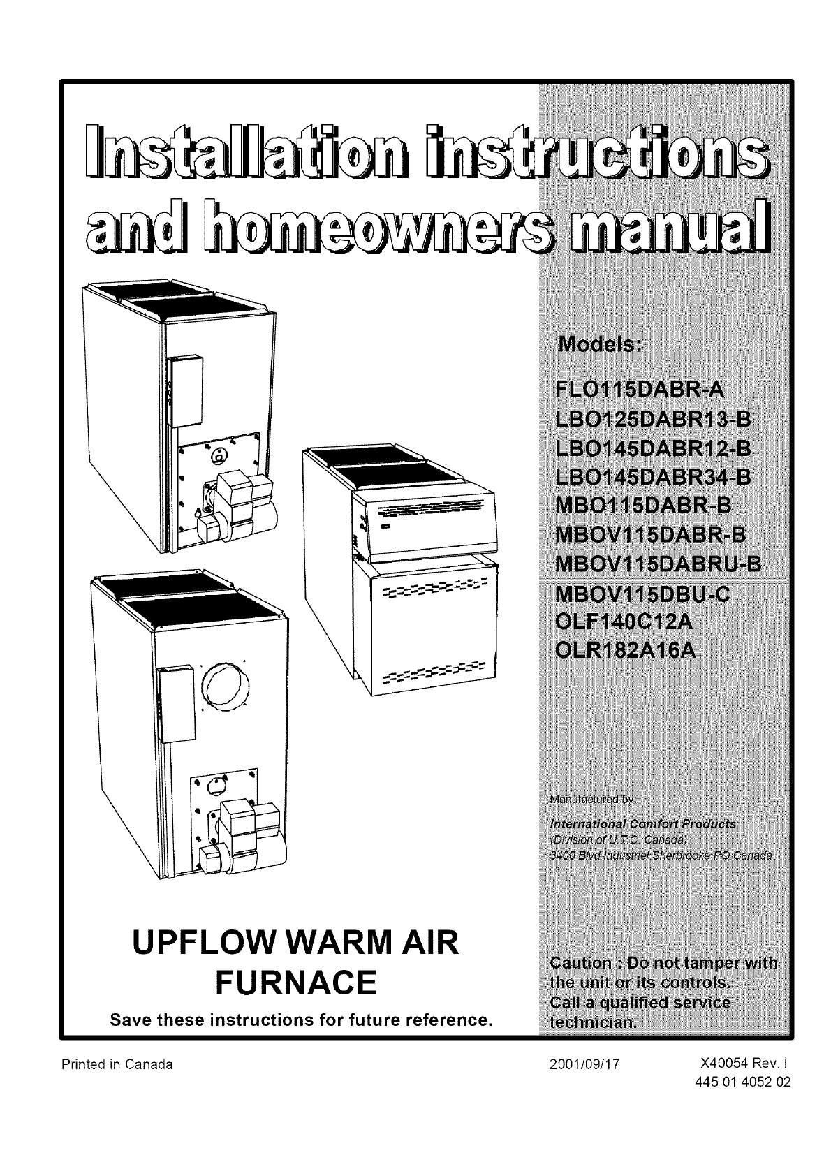
UPFLOW WARM AIR
FURNACE
Save these instructions for future reference.
Printed in Canada 2001/09/17 X40054 Rev. I
445 01 4052 02
PART 1
INSTALLATION
2) SAFE INSTALLATION REQUIREMENTS
1) SAFETY LABELLING AND SIGNAL WORDS
Installation or repairs made by unqualified persons
can result in hazards to you a nd others. Installation
MUST conform with codes or, in the absence of
local codes, with codes of the country having
jurisdiction.
The information contained in this manual is
intended for use by a qualified service technician
familiar with safety procedures and equipped with
the proper tools and test instruments.
Failure to carefully read and follow all instructions
in this manual can result in furnace malfunction,
property damage, personal injury and/or death.
1.1) Danger, Warning and Caution:
The signal words DANGER, WARNING and CAUTION are used to
identify levels of hazard seriousness. The signal word DANGER is
only used in product labels to signify an immediate hazard. Thes_
words WARNING and CAUTION will be used on product labels and
throughout this manual and other manuals that may apply to the
product.
1.2) Signal Words:
DANGER- Immediate hazards which WILL result in death or serious
injury.
WARNING - Hazards or unsafe practices which COULD result in
death or injury.
CAUTION - Hazards or unsafe practices which COULD result in
personal injury or product or property damage.
1.3) Signal Words in Manuals:
The signal word WARNING is used throughout this manual in the
following manner:
The signal word CAUTION is used throughout this manual in the
following manner:
ICAUTION ]
Fire hazard
The furnace must be installed in a level position,
never where it will slope to the front.
If the furnace were installed in that position, oil
could drain into the furnace vestibule and create a
fire hazard, instead of draining properly into the
combustion chamber.
INOTE: It is the personal responsibility and obligation of the customer
to contact a qualified installer to ensure that the installation is
adequate and conforms to governing codes and ordinances.
a. This furnace is NOT approved for installation in mobile homes,
trailers or recreation vehicles.
b. You must have asufficient supply of fresh air for combustion and
ventilation to the area in which the furnace is located.
c. Do NOT use this furnace as aconstruction heater or to heat a
building that is under construction.
d. Use only the Type of fuel oil approved for this furnace (see
Rating Plate on unit). Overfiring will result in failure of heat
exchanger and cause dangerous operation.
e. Visually check all oil line joints for signs of wetness, which would
indicate a leak.
f. Connect furnace to the chimney.
g. The points in Part 2 "Operation" are vital to the proper and safe
operation of the heating system. Take the time to be sure they
are all done.
h. Follow the rules of the NFPA Pamphlet No.31 (for USA) and B-
139 (for Canada) or local codes for locating and installing the oil
storage tank.
i. Follow aregular service and maintenance schedule for efficient
and safe operation.
j. Beforeservicing,allowfumacetocool.Alwaysshutoffelectricity
andfueltofurnacewhenservicing.Thiswllpreventelectrical
shockorburns.
k. Sealsupplyandreturnairducts.
I. TheventsystemMUSTbecheckedtodeterminethatitisthe
correcttypeandsize.
m. Installcorrectfiltertypeandsize.
n. UnitMUSTbeinstalledsoelectricalcomponentsareprotected
fromdirectcontactwithwater.
2.1) Safety Rules:
Your unit is built to provide many years of safe and dependable
service providing it is properly installed and maintained. However,
abuse and/or improper use can shorten the life of the unit and create
hazards for you, the owner.
The U.S. Consumer Product Safety Commission recommends
that users of oil-burning appliances install carbon monoxide
detectors. There can be various sources of carbon monoxide in
a building or dwelling. The sources could be gas-fired clothes
dryers, gas cooking stoves, water heaters, furnaces, gas-fired
fireplaces, wood fireplaces, and several other items. Carbon
monoxide can cause serious bodily injury and/or death.
Therefore, to help alert people of potentially dangerous carbon
monoxide levels, you should have carbon monoxide detectors
listed by a nationally recognised agency (e.g. Underwriters
Laboratories or Intemational Approval Services) installed and
maintained in the building or dwelling (see Note).
There can be numerous sources of fire or smoke in a building or
dwelling. Fire or smoke can cause serious bodily injury, death,
and/or property damage. Therefore, in order to alert people of
potentially dangerous fire or smoke, you should have fire and
smoke detectors listed by Underwriters Laboratories installed
and maintained in the building or dwelling (see Note below).
NO-I_: The manufacturer ot your furnace does not test any detectors
and makes no representations regarding any brand or type of
detector.
CAUTION
Insure that the area around the combustion air intake
terminal is free of snow, ice and debris.
CAUTION
Do not use any commercially available soot remover.
This furnace has fiber type refractory combustion
chamber. Normal servicing of this unit does not require
cleanings of the combustion chamber. Use extreme
care if for any reason you have to work in the area of
the combustion chamber.
2.2) Freezing Temperature and Your
Structure:
Freeze warning.
Turn off water system.
If your unit remains shut off during cold weather the
water pipes could freeze and burst, resulting in
serious water damage.
Your unit is equipped with safety devices that may keep it from
operating if sensors detect abnormal conditions such as clogged
exhaust flues.
If the structure will be unattended during cold weather you should take
these precautions.
a. Turn off main water supply into the structure and drain the water
lines if possible. Open faucets in appropriate areas.
Have someone check the structure frequently during cold
weather to make sure it is warm enough to prevent pipes from
freezing. Suggest they call a qualified service agency, if
required.
2.3) Installation regulation:
All local and national code requirements governing the installation of
oil buming equipment, wiring and flue connections MUST be followed.
Some of the codes that may be applicable are:
CSA B139 INSTALLATION CODE FOR OIL
BURNING EQUIPMENT
NFPA31 INSTALLATION OF OIL BURNING
EQUIPMENT
ANSI/NFPA90B WARM AIR HEATING AND AIR
CONDI-tqONING SYSTEMS
ANSI/NFPA 70 NATIONAL ELECTRICAL CODE
CSA C22.2 No3 CANADIAN ELECTRICAL CODE
Only the latest issues of the above codes should be used.
3) LOCATING THE FURNACE
CAUTION
Check carefully your furnace upon delivery for any
evidence of damage that may have occurred during
shipping and handling. Any claims for damages or lost
parts must be made with the Transport Company.
This furnace is approved for reduced clearances to combustible
construction, therefore, it may be installed in a closet or similar
enclosure and in any case, the unit should always be installed level.
In a basement, or when installed on the floor (as in a crawlspace), it is
recommended that the unit be installed on a concrete pad that is 1"to
2" thick.
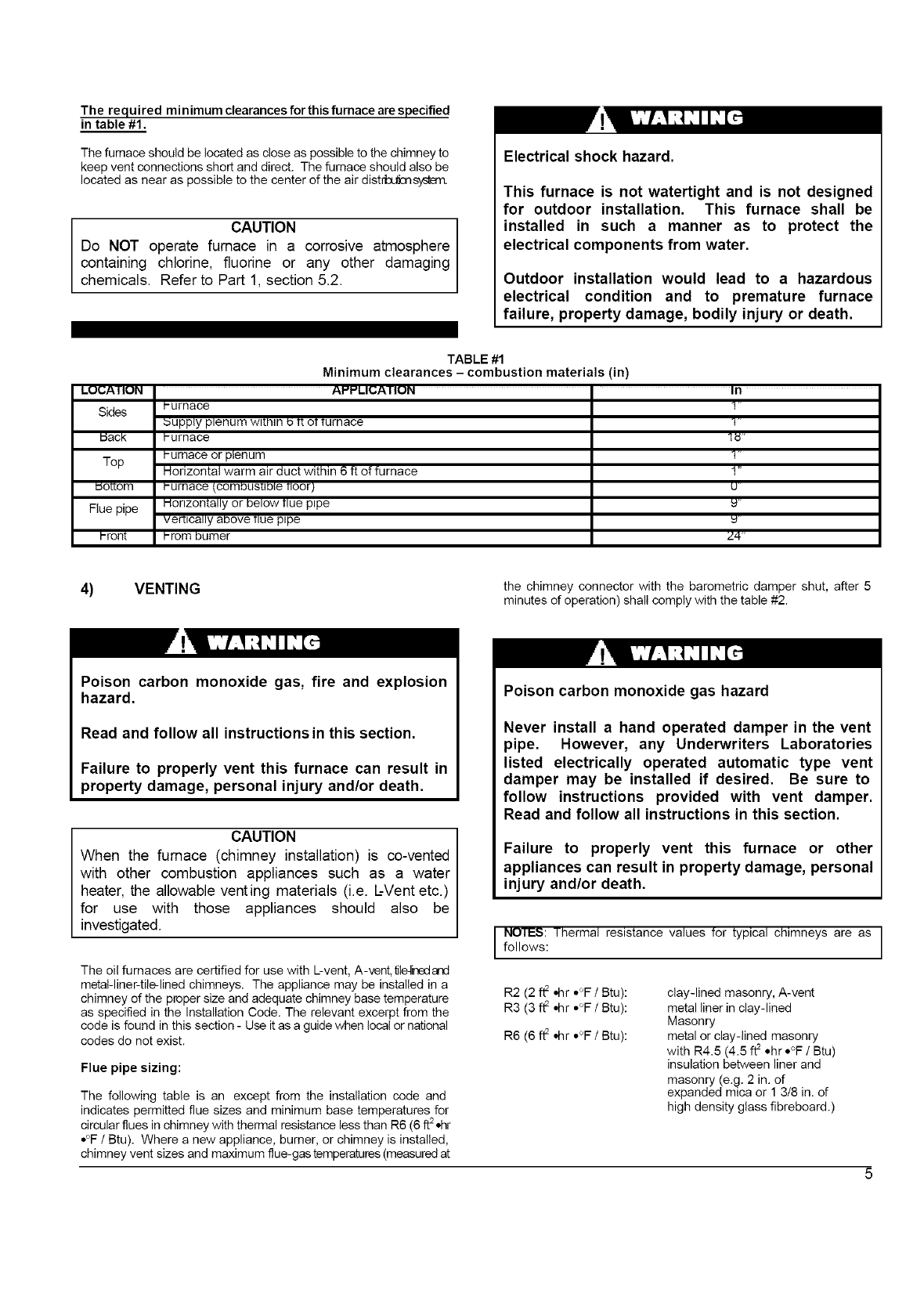
The required minimum clearances for this furnace are specified
in table #1,
The furnace should be located as close as possible to the chimney to
keep vent connections short and direct. The furnace should also be
located as near as possible to the center of the air dist_sys_m.
CAUTION
Do NOT operate furnace in a corrosive atmosphere
containing chlorine, fluorine or any other damaging
chemicals. Refer to Part 1, section 5.2.
Electrical shock hazard.
This furnace is not watertight and is not designed
for outdoor installation. This furnace shall be
installed in such a manner as to protect the
electrical components from water.
Outdoor installation would lead to a hazardous
electrical condition and to premature furnace
failure, property damage, bodily injury or death.
LUi.;A I IUN
Sides
IJacK
Top
_eEom
Flue pipe
I-font
TABLE #1
Minimum clearances - combustion materials (in)
AffffLIt.;A I IUN "In
Purnace
supply plenum w_[n_nb T[OTTurnace
Purnace
humace or plenum
Horizontal warm air duct within 6 ft of furnace
Pumace (combusuble floor)
Honzontally or below flue pipe
verciCally above flue p_pe
Prom burner
1"
U-
Z4"
4) VENTING the chimney connector with the barometric damper shut, after 5
minutes of operation) shall comply with the table #2.
Poison carbon monoxide gas, fire and explosion
hazard.
Read and follow all instructions in this section.
Failure to properly vent this furnace can result in
property damage, personal injury and/or death.
CAUTION
When the furnace (chimney installation) is co-vented
with other combustion appliances such as a water
heater, the allowable venting materials (i.e. L-Vent etc.)
for use with those appliances should also be
investigated.
The oil furnaces are certified for use with L-vent, A-vent, tileqinedand
metal-liner-tile-lined chimneys. The appliance may be installed in a
chimney of the proper size and adequate chimney base temperature
as specified in the Installation Code. The relevant excerpt from the
code is found in this section - Use it as a guide when loca! or national
codes do not exist.
Flue pipe sizing:
The following table is an except from the installation cede and
indicates permitted flue sizes and minimum base temperatures for
circular flues in chimney with thermal resistance less than R6 (6 ft 2ohr
°°F /Btu). Where a new appliance, burner, or chimney is installed,
chimney vent sizes and maximum flue-gas temperatures (measured at
Poison carbon monoxide gas hazard
Never install a hand operated damper in the vent
pipe. However, any Underwriters Laboratories
listed electrically operated automatic type vent
damper may be installed if desired. Be sure to
follow instructions provided with vent damper.
Read and follow all instructions in this section.
Failure to properly vent this furnace or other
appliances can result in property damage, personal
injury and/or death.
I NOTES: Thermal resistance values tot typical chimneys are as
follows:
R2 (2 ft2 .hr °°F /Btu):
R3 (3 ft2 .hr .°F /Btu):
R6 (6 ft2 .hr °°F /Btu):
clay-lined masonry, A-vent
metal liner in clay-lined
Masonry
metal or clay-lined masonry
with R4.5 (4.5 • ohr *°F /Btu
insulation between liner and
masonry (e.g. 2 in. of
expanded mica or 1 3/8 in. of
high density glass fibreboard.
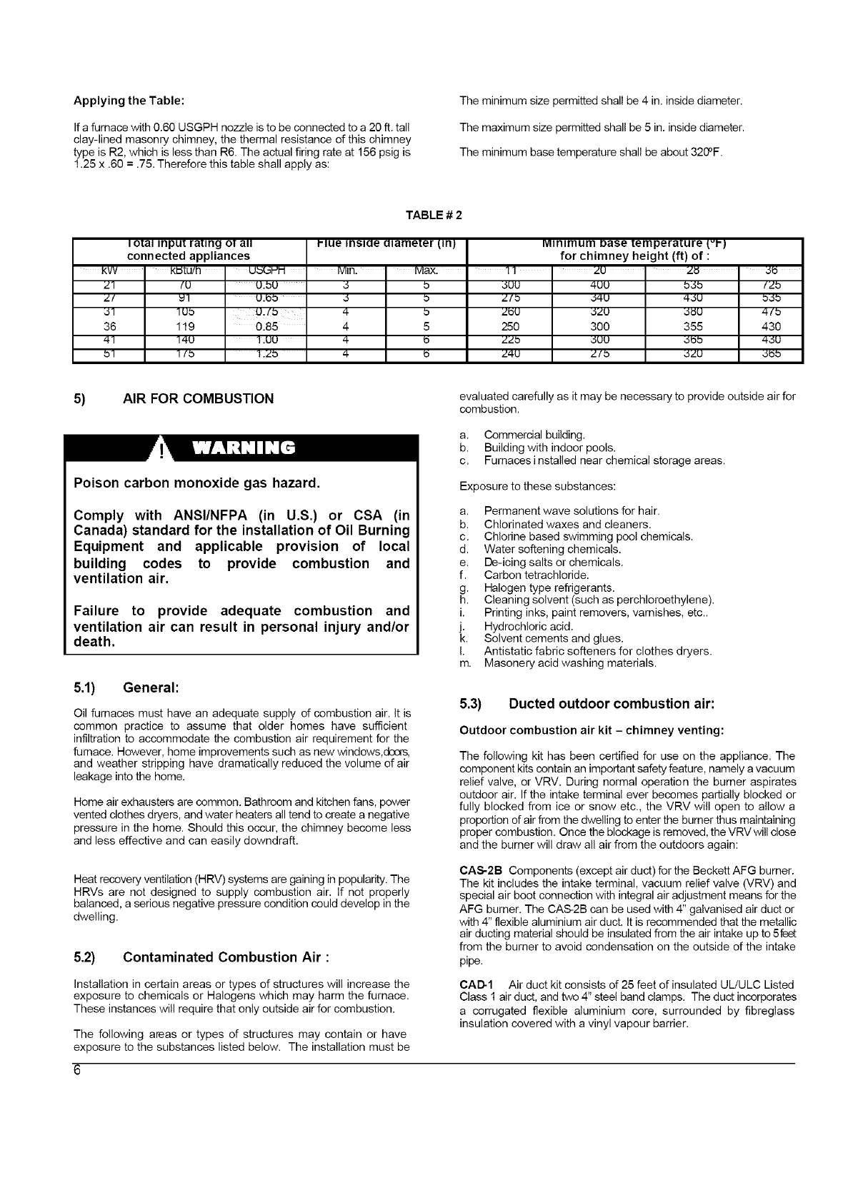
ApplyingtheTable:
Ifafumacewith0.60USGPHnozzleistobeconnectedtoa20ft.tall
clay-linedmasonrychimney,thethermalresistanceofthischimney
typeisR2,whichislessthanR6.Theactualfiringrateat156psigis
1.25x.60 = .75. Therefore this table shall apply as:
The minimum size permitted shall be 4 in. inside diameter.
The maximum size permitted shall be 5 in. inside diameter.
The minimum base temperature shall be about 320°F.
TABLE # 2
Ioral Input rating o1 all
connected appliances
KVV
Z7
Z/
`57
36
47
b7
KI_tU/13 U_LSI-_i
(U U.bU
_1 U._Ob
lub U,/b
119 0.85
74U 1.UU
7(b 1.Zb
Hue inslae alameter (,in}
Ivl_n. • Ivlax.
,5 b
,.1 b
4 b
4 5
4 b
4
Minimum base temperature (,vt-)
for chimney height (ft) of :
11
`SUU
Z/b
ZbU
25O
ZZb
Z4U
zu
4UU
`5_u
`szu
3OO
`suu
Z/b
b`sb (Zb
_JU bJb
`5_U 4/b
355 430
`5_b 4`5U
`SZU `5_b
5) AIR FOR COMBUSTION
Poison carbon monoxide gas hazard.
Comply with ANSI/NFPA (in U.S.) or CSA (in
Canada) standard for the installation of Oil Burning
Equipment and applicable provision of local
building codes to provide combustion and
ventilation air.
Failure to provide adequate combustion and
ventilation air can result in personal injury and/or
death.
5.1) General:
Oil furnaces must have an adequate supply of combustion air. It is
common practice to assume that older homes have sufficient
infiltration to accommodate the combustion air requirement for the
furnace. However, home improvements such as new windows,dco_
and weather stripping have dramatically reduced the volume of air
leakage into the home.
Home air exhausters are common. Bathroom and kitchen fans, power
vented clothes dryers, and water heaters all tend to create a negative
pressure in the home. Should this occur, the chimney become less
and less effective and can easily downdraft.
Heat recovery ventilation (HRV) systems are gaining in popularity. The
HRVs are not designed to supply combustion air. If not properly
balanced, a serious negative pressure condition could develop in the
dwelling.
5.2) Contaminated Combustion Air :
Installation in certain areas or types of structures will increase the
exposure to chemicals or Halogens which may harm the furnace.
These instances will require that only outside air for combustion.
The following areas or types of structures may contain or have
exposure to the substances listed below. The installation must be
evaluated carefully as it may be necessary to provide outside air for
combustion.
a. Commercial building.
b. Building with indoor pools.
c. Furnacesinstalled near chemical storage areas.
Exposure to these substances:
a. Permanent wave solutions for hair.
b. Chlorinated waxes and cleaners.
c. Chlorine based swimming pool chemicals.
d. Water softening chemicals.
e. De-icing salts or chemicals.
f. Carbon tetrachloride.
g. Halogen type refrigerants.
h. Cleaning solvent (such as perchloroethylene).
i. Printing inks, paint removers, vamishes, etc..
j. Hydrochloric acid.
k. Solvent cements and glues.
I. Antistatic fabric softeners for clothes dryers.
m. Masonery acid washing materials.
5.3) Ducted outdoor combustion air:
Outdoor combustion air kit - chimney venting:
The following kit has been certified for use on the appliance. The
component kits contain an important safety feature, namely a vacuum
relief valve, or VRV. During normal operation the bumer aspirates
outdoor air. If the intake terminal ever becomes partially blocked or
fully blocked from ice or snow etc., the VRV will open to allow a
proportion of air from the dwelling to enter the burner thus maintaining
proper combustion. Once the blockage is removed, the VRV will close
and the burner will draw all air from the outdoors again:
CAS-2B Components (except air duct) for the Beckett AFG bumer.
The kit includes the intake terminal, vacuum relief valve (VRV) and
special air boot connection with integral air adjustment means for the
AFG burner. The CAS-2B can be used with 4" galvanised air duct or
with 4" flexible aluminium air duct. It is recommended that the metallic
air ducting material should be insulated from the air intake up to 5feet
from the burner to avoid condensation on the outside of the intake
pipe.
CAD-1 Air duct kit consists of 25 feet of insulated UL/ULC Listed
Class 1 air duct, and two 4" steel band clamps. The duct incorporates
a corrugated flexible aluminium core, surrounded by fibreglass
insulation covered with a vinyl vapour barrier.
CAUTION
The CAS-2B does not turn the furnace installation into a
direct vent system. Therefore the building structure
must provide for adequate combustion air to be
delivered at the vacuum relief valve. The burner will
need to draw combustion air from the VRV's
surroundings if the intake ever becomes blocked.
Therefore non-direct vent installation codes must be
followed.
Comprehensive installation instructions are provided with the kit.
6) OIL TANKS AND LINES
Check your local codes for the installation of the tank and accessories.
A manual shut-off valve and an oil filter shall follow sequence from
tank to burner. Be sure that the oil line is clean before connecting to
the burner, The oil line should be protected to eliminate any possible
damage. Installations having the fuel oil tank below the bumer level
must employ a two pipe fuel supply system with an appropriate fuel
pump (more than 8' lift use 2 stage pump and more tt-an 16' an
auxiliary pump).
Follow the pump instructions to determine the size of tubing you need
in relation of the lift, or the horizontal distance.
7) BURNER INSTALLATION
Mounting the burner:
a.
b.
The warm air furnace burner mounting plate has a four bolts
configuration.
Position the mounting gasket between the mounting flange and
the appliance burner mounting plate. Line up the holes in the
mounting flange with the studs on the appliance mounting plate
and securely bolt in place.
After the burner is mounted:
a. Remove drawer assembly or air tube combination
b. Install nozzle (see specifications)
c. Confirm electrode settings
d. Make the electrical connections
e. Complete oil line connections
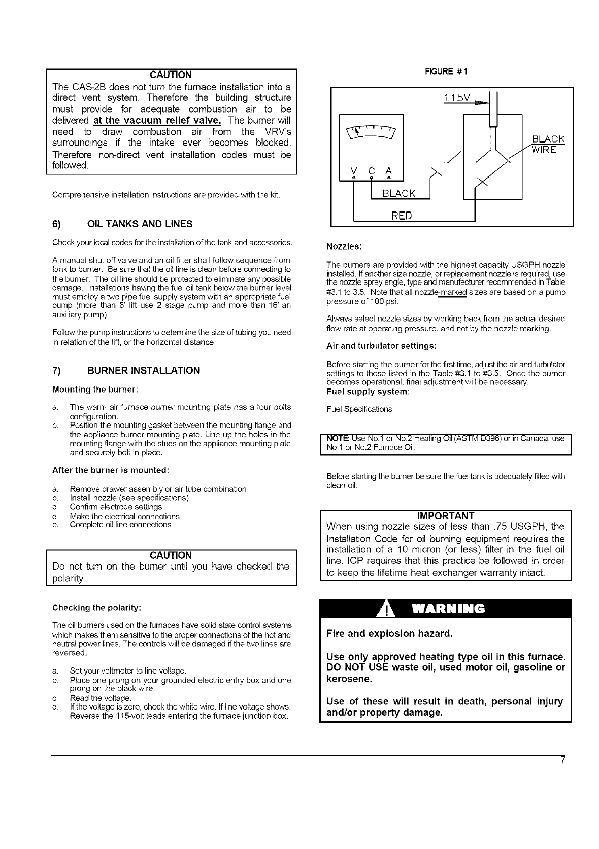
CAUTION
Do not turn on the burner until you have checked the
polarity
RGURE #1
.i
[ BLACKJ>"
[ RED
BLACK
Nozzles:
The burners are provided with the highest capacity USGPH nozzle
installed. If another size nozzle, or replacement nozzle is required, use
the nozzle spray angle, type and manufacturer recommended in Table
#3.1 to 3.5. Note that all nozzle-marked sizes are based on a pump
pressure of 100 psi.
Always select nozzle sizes by working back from the actual desired
flow rate at operating pressure, and not by the nozzle marking.
Air and turbulator settings:
Before starting the bumer for the first time, adjust the air and turbulator
settings to those listed in the Table #3.1 to #3.5. Once the bumer
becomes operational, final adjustment will be necessary.
Fuel supply system:
Fuel Specifications
I NOTE= Use No.1 or No.2 Heating Oil (ASTM D396) or in Canada, use
No.1 or No.2 Furnace Oil.
Before starting the burner be sure the fuel tank is adequately filled with
clean oil.
IMPORTANT
When using nozzle sizes of less than .75 USGPH, the
Installation Code for oil burning equipment requires the
installation of a 10 micron (or less) filter in the fuel oil
line. ICP requires that this practice be followed in order
to keep the lifetime heat exchanger warranty intact.
Checking the polarity:
The oil bumers used on the furnaces have solid state control systems
which makes them sensitive to the proper connections of the hot and
neutral power lines. The controls will be damaged if the two lines are
reversed.
a. Set your voltmeter to line voltage.
b. Place one prong on your grounded electric entry box and one
prong on the black wire.
c. Read the voltage.
d. If the voltage is zero, check the white wire. If line voltage shows.
Reverse the 115-volt leads entering the furnace junction box.
Fire and explosion hazard.
Use only approved heating type oil in this furnace.
DO NOT USE waste oil, used motor oil, gasoline or
kerosene.
Use of these will result in death, personal injury
and/or property damage.
NOTE You may notice a slight odor the tirst time your tumace is
operated. This will soon disappear. It is only the oil used on the parts
during manufacturing.
8) INSTALLING ACCESSORIES
Electrical shock hazard.
Turn OFF electric power at fuse box or service
panel before making any electrical connections and
ensure a proper ground connection is made before
connecting line voltage.
Failure to do so could result in property damage,
bodily injury or death.
8.4) Ductwork and Filter:
Installation:
Design and install air distribution system to comply with Air
Conditioning Contractors of America manuals or other approved
methods that conform to local codes and good trade practices.
When furnace supply ducts carry air outside furnace area, seal return
air duct to furnace casing and terminate duct outside furnace space.
Install air conditioning cooling coil (evaporator)on downstream side (in
the supply air plenum) or furnace.
If separate evaporator and blower unit is used, install good sealing
dampers for air flow control. Cold air from the evaporator coil going
through the furnace could cause condensation and shorten furnace
life.
I CAUTIONDampers (purchased locally) MUST be automatic.
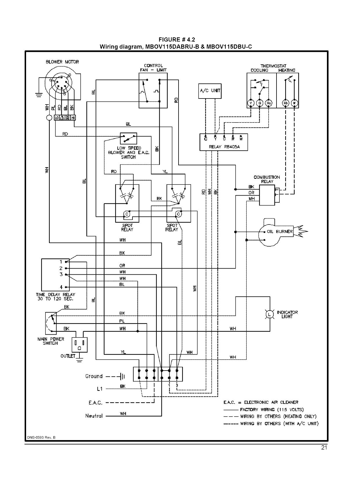
8.1) Electronic air cleaner (E.A.C.):
Wire leads are provided to direct 115 volts @ 0.5 Amp maximum to an
electronic air cleaner (EAC).Power will be available to the E.A.C when
E.A.C switch is on or during heating speed blower operation. Wire the
electronic air cleaner as indicated in the wiring diagram (figures # 4.1,
# 4.2 and # 4.3).
8.2) Humidifier:
Terminals are provided to direct 115 volts @ 1.0 Amp maximum to the
transformer powering the humidifier. The humidifier will be energised
anytime the blower is operating on the "Heating Speed". Wire the
115-volts power as indicated in figures # 4.1, # 4.2 and # 4.3.
8.3) Air conditioning:
An air conditioning coil may be installed on the _side only.
Also, notwithstanding the evaporator ceil manufacturer's instructions,
a minimum of 6 inches clearance must be allowed between the bottom
of the coil drain pan, and the top of the heat exchanger. Wire the
thermostat and condensing unit contactor as indicated in the wiring
diagram (figures # 4.1, # 4.2 and # 4.3).
Poison carbon monoxide gas hazard.
Do NOT draw return air from inside a closet or
utility room. Return air duct MUST be sealed 1o
furnace casing.
Failure to properly seal duct can result in death,
personal injury and/or property damage.
Poison carbon monoxide gas hazard.
Install evaporator coil on the supply side of the
furnace ducting.
Evaporator coil installed in return side ducting can
cause condensation to form inside heat exchanger
resulting in heat exchanger failure. This could
result in death, personal injury and/or property
damage.

PART 2
OPERATION
1) SEQUENCE OF OPERATION
1.1) Sequence of operation - Beckett AFG, Riello
40-F and Aero F-FAC:
1. Normally open contact (T-T) on primary relay closed when
thermostat calls for heat.
AFG and F-FAC burner: The motor starts and spark is
established. The pump pressure builds and the poppet valve
opens admitting fuel to the nozzle. Pressure builds and poppet
valve opens, allowing oil to flow through nozzle.
40F: Burner motor starts. The burner motor fan pre-purgesthe
combustion chamber and vent for 10 seconds, establishing the
combustion air pattern. During this time the solenoid valve
holding coil pressure will be approximately 100 psig. Solenoid
valve opens, allowing oil to flow through nozzle. At the same
time, the bumer motor's ignition coil produces spark.
3. Spark ignites oil droplets.
4. Cad cell senses flame and burner continues to fire. Ignition
transformer ceases sparking (Riello R40-F).
5. After fan-limit control heats up to the factory set point, the
circulating air blower and electronic air cleaner starts.
6. The circulating air blower and burner motor remain on until the
thermostat is satisfied (AFG). The ignition transformer continues
to spark (AFG). The solenoid valve remains open (R40-F).
7. Thermostat is satisfied.
8. Primary relay contacts open, solenoid valve closes (R40-F),
burner fan motor shuts down. The ignition transformer ceases
sparking (AFG).
9. The fan-limit control BI-metal cools down to the factory set point
of 90 degrees Fahrenheit, the circulating air blower and the
electronic air cleaner turns off.
2) CHECKS AND ADJUSTMENTS
2.1) General:
During initial start-up and subsequent yearly maintenance calls, the
furnace must be thoroughly tested.
IMPORTANT
The burner must be put in operation for at least 10
minutes before any test readings are taken. For new
installations, set up the burner to the settings (see table
# 3.1 to # 3.5), before firing. These are rough
adjustments but they will ensure that the burner will
start and run smoke-free in advance of the fine
adjustments being made.
Open the oil bleed port screw and start the burner. Allow the oil to
flush into a portable container for at least 10 seconds. Slowly close the
bleed screw- the oil should flow absolutely free of white streaks or
bubbles to indicate that no air is being drawn into the suction side of
the oil piping and pump. Tighten the bleed screw and the burner will
fire. Adjust the oil pressure as indicated in Table # 3.1 to # 3.5.
2.2) Restart if Burner Should Stop:
1. Set thermostat lower than the room temperature.
2. Press the reset button on the burner primary control (relay).
3. Set thermostat higher than the room temperature.
4. If the burner motor does not start or ignition fails, turn off the
disconnect switch and CALL YOUR SERVICEMAN
I CAUTION
Do not attempt to start the burner when excess oil has
accumulated, when the furnace is full of vapour, or
when the combustion chamber is very hot.
2.3) Combustion chamber curing:
Some moisture and binders remain in the ceramic combustion
chambers after fabrication. It is important to clear the chamber of
these residues before testing. If you smoke test before curing, the
instrument may become damaged. To cure the chamber, run the unit
for 3 consecutive cycles, with 3 minutes of elapsed time in between
each cycle. Each burn cycle should be 3 minutes duration. The
exhaust will have a pungent odor and produce a white cloud of steam.
2.4)
1.
4,
5.
Perform the smoke /C02 test:
Pierce a test hole in the smoke pipe near the furnace breech.
Insert the smoke test instrument probe into the open hole.
Starting with a zero smoke reading, gradually reduce the burner
air setting until just a trace (#1 on Bacharach Scale) of smoke
results.
Take a CO2 sample at the same test location where the smoke
sample was taken. Note the CO2 reading associated with the #1
smoke condition.
Adjust the burner air setting to obtain a CO2 reading 1% lower
than the reading associated with the #1 smoke.
This method of adjusting the CO2 will allow adequate excess air
to ensure that the bumer will burn clean for the entire heating
season.
2.5) Perform the supply air temperature rise test:
1. Operate the burner for at least 10 minutes.
2. Measurethe temperatureof the air inthe return air plenum.
3. Measurethe temperatureof the air inthe largesttrunk comingoff
the supply air plenum, just "out of the lineof sighf'of theradiation
comingoffthe heat exchanger;12" away fromthe plenumonthe
main take-off usually satisfies this objective.
9
4,
5.
The temperature rise is calculated by subtracting the return air
temperature from the supply air temperature.
If the temperature rise exceeds the temperature specified in table
# 3.1 to # 3.5, change to the next higher blower speed tap until
the temperature rise falls to at this temperature or below. If the
excessive temperature rise cannot be reduced by increasing fan
speed, investigate for ductwork restriction(s), dirty or improper air
filter, or overfiring caused by excessive pump pressure, or
inproper nozzle sizing.
2.6) Vent temperature test:
1. Place a thermometer in the test hole located in the breech pipe.
2. The vent temperature should be between 400 and 575°F. If
not, check for improper air temperature rise, pump pressure,
nozzle size, or for a badly sooted heat exchanger.
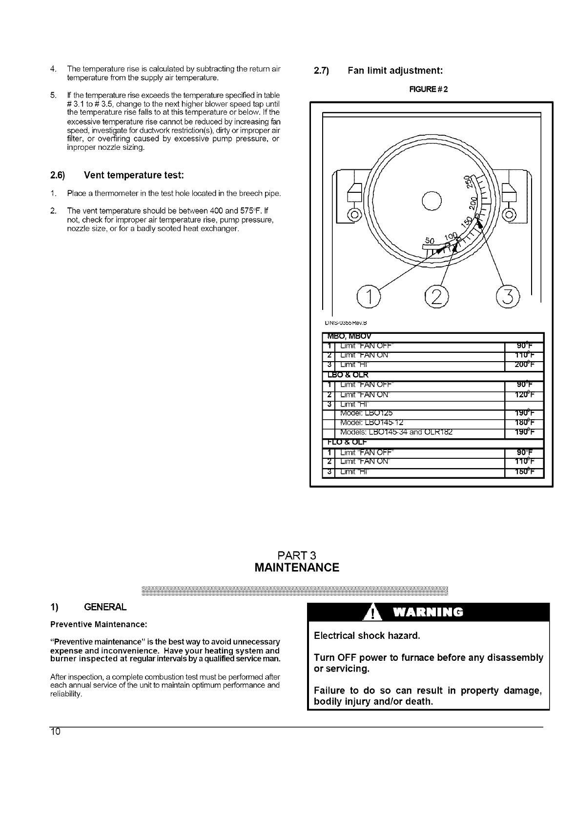
2.7) Fan limit adjustment:
FIGURE # 2
13N _5-O3bb I_ev._
MkSU,MI_UV
I I LIm_t"'PANUhl- I_U°I"
ZLimit 'i-_lN UIN 11U°_ -
;:1 Limit "HI ZUU°I-
LIdU & ULI'(
Limit "PAN UN 1ZU°I-
Limit I-Ii
ivloclei:L_UI Zb 3IdU°t-
Model LUUI4b-I Z
Models: LIJU14b-34 and ULN1UZ I_U°P
I-LU &ULI-
LImR "PAN OPP" 90vF
Limit "PAN UN 11U°P
Limit "MI I bU°P
PART 3
MAINTENANCE
1) GENERAL
Preventive Maintenance:
"Preventive maintenance" is the best way to avoid unnecessary
expense and inconvenience. Have your heating system and
burner inspected at regular intervals by a qualified service man.
After inspection, a complete combustion test must be performed after
each annual service of the unit to maintain optimum performance and
reliability.
Electrical shock hazard.
Turn OFF power to furnace before any disassembly
or servicing.
Failure to do so can result in property damage,
bodily injury and/or death.
10
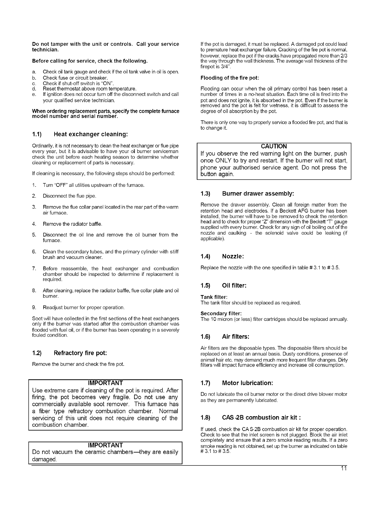
Do not tamper with the unit or controls. Call your service
technician.
Before calling for service, check the following.
a. Check oil tank gauge and check if the oil tank valve in oil is open.
b. Check fuse or circuit breaker.
c. Check if shut-off switch is "ON".
d. Reset thermostat above room temperature.
e. If ignition does not occur turn off the disconnect switch and call
your qualified service technician.
When ordering replacement parts, specify the complete furnace
model number and serial number.
1.1) Heat exchanger cleaning:
Ordinarily, it is not necessary to clean the heat exchanger or flue pipe
every year, but it is advisable to have your o_ burner serviceman
check the unit before each heating season to determine whether
cleaning or replacement of parts is necessary.
If cleaning is necessary, the following steps should be perfomed:
1. Turn "OFF" all utilities upstream of the furnace.
2. Disconnect the flue pipe.
3. Remove the flue collar panel located in the rear part of the warm
air furnace.
4. Remove the radiator baffle.
5. Disconnect the oil line and remove the oil burner from the
furnace.
6. Clean the secondary tubes, and the primary cylinder with stiff
brush and vacuum cleaner,
7. Before reassemble, the heat exchanger and combustion
chamber should be inspected to determine if replacement is
required.
8. After cleaning, replace the radiator baffle, flue collar plate and oil
burner.
9. Readjust burner for proper operation.
Soot will have collected in the first sections of the heat exchangers
only if the burner was started after the combustion chamber was
flooded with fuel oil, or if the burner has been operating in a severely
fouled condition.
1.2) Refractory fire pot:
Remove the burner and check the fire pot.
IMPORTANT
Use extreme care if cleaning of the pot is required. After
firing, the pot becomes very fragile. Do not use any
commercially available soot remover. This furnace has
a fiber type refractory combustion chamber. Normal
servicing of this unit does not require cleaning of the
combustion chamber.
IMPORTANT
Do not vacuum the ceramic chambers_hey are easily
damaged.
If the pot is damaged, it must be replaced. A damaged pot could lead
to premature heat exchanger failure. Cracking of the fire pot is normal,
however, replace the pot if the cracks have propagated more than 2/3
the way through the wall thickness. The average wall thickness of the
firepot is 3/4".
Flooding of the fire pot:
Flooding can occur when the oil primary control has been reset a
number of times in a no-heat situation. Each time oil is fired into the
pot and does not ignite, it is absorbed in the pot. Even if the burner is
removed and the pot is felt for wetness, it is difficult to assess the
degree of oil absorption by the pot.
There is only one way to properly service a flooded fire pot, and that is
to change it.
CAUTION
If you observe the red warning light on the burner, push
once ONLY to try and restart. If the burner will not start,
phone your authorised service agent. Do not press the
button again.
1.3) Burner drawer assembly:
Remove the drawer assembly. Clean all foreign matter from the
retention head and electrodes. If a Beckett AFG burner has been
installed, the burner will have to be removed to check the retention
head and to check for proper "Z" dimension with the Beckett "T" gauge
supplied with every burner. Check for any sign of oil boiling out of the
nozzle and caulking - the solenoid valve could be leaking (if
applicable).
1.4) Nozzle:
Replace the nozzle with the one specified in table # 3.1 to # 3.5.
1.5) Oil filter:
Tank filter:
The tank filter should be replaced as required.
Secondary filter:
The 10 micron (or less) filter cartridges should be replaced annually.
1.6) Air filters:
Air filters are the disposable types. The disposable filters should be
replaced on at least an annual basis. Dusty conditions, presence of
animal hair etc. may demand much more frequent filter changes. Dirty
filters will impact furnace efficiency and increase oil consumption.
1.7) Motor lubrication:
Do not lubricate the oil burner motor or the direct drive blower motor
as they are permanently lubricated.
1.8) CAS -2B combustion air kit :
If used, check the CA S-2B combustion air kit for proper operation.
Check to see that the inlet screen is not plugged. Block the air inlet
completely and ensure that a zero smoke reading results. If a zero
smoke reading is not obtained, set up the burner as indicated on table
#3.1 to # 3.5.
11
Gradually block off the intake. The CO2 should increase by a
maximum of 0.5 percentage points at the fully blocked condition. If not,
check that the VRV gate is pivoting freely and that the pivot rod is in a
horizontal position. Also, check that the counterweight has been
properly adjusted in accordance with the CAS-2B installation
instructions.
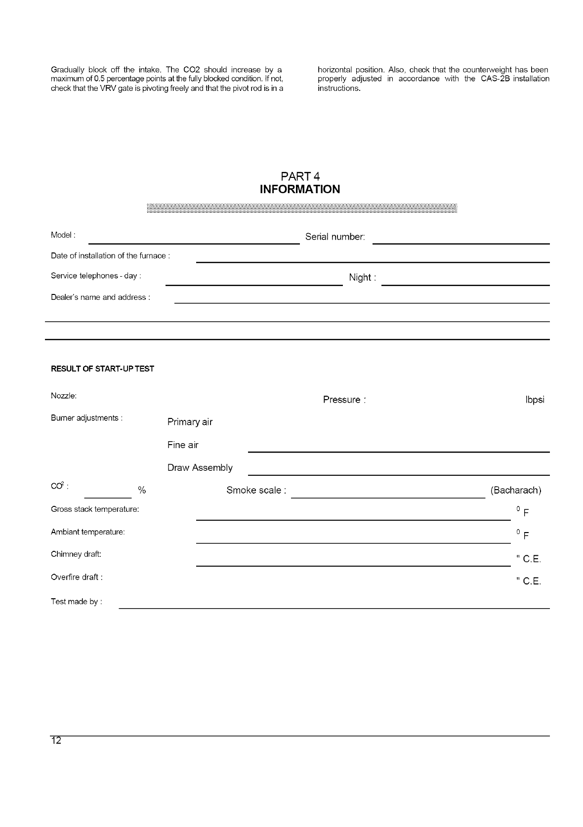
PART 4
INFORMATION
Model:
Date of installation of the furnace :
Service telephones - day :
Serial number:
Night :
Dealer's name and address :
RESULT OF START-UP TEST
Nozzle:
Burner adjustments :
co2: %
Gross stack temperature:
Ambiant temperature:
Chimney draft:
Overfire draft
Test made by
Primary air
Fine air
Draw Assembly
Smoke scale :
Pressure : Ibpsi
(Bacharach)
o F
o F
12
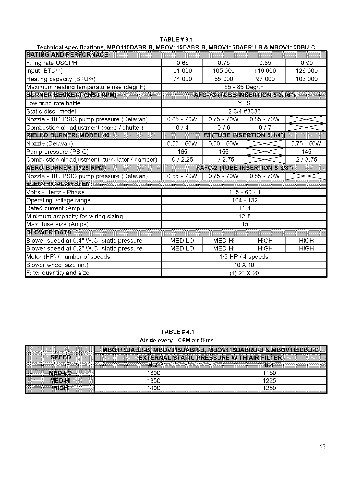
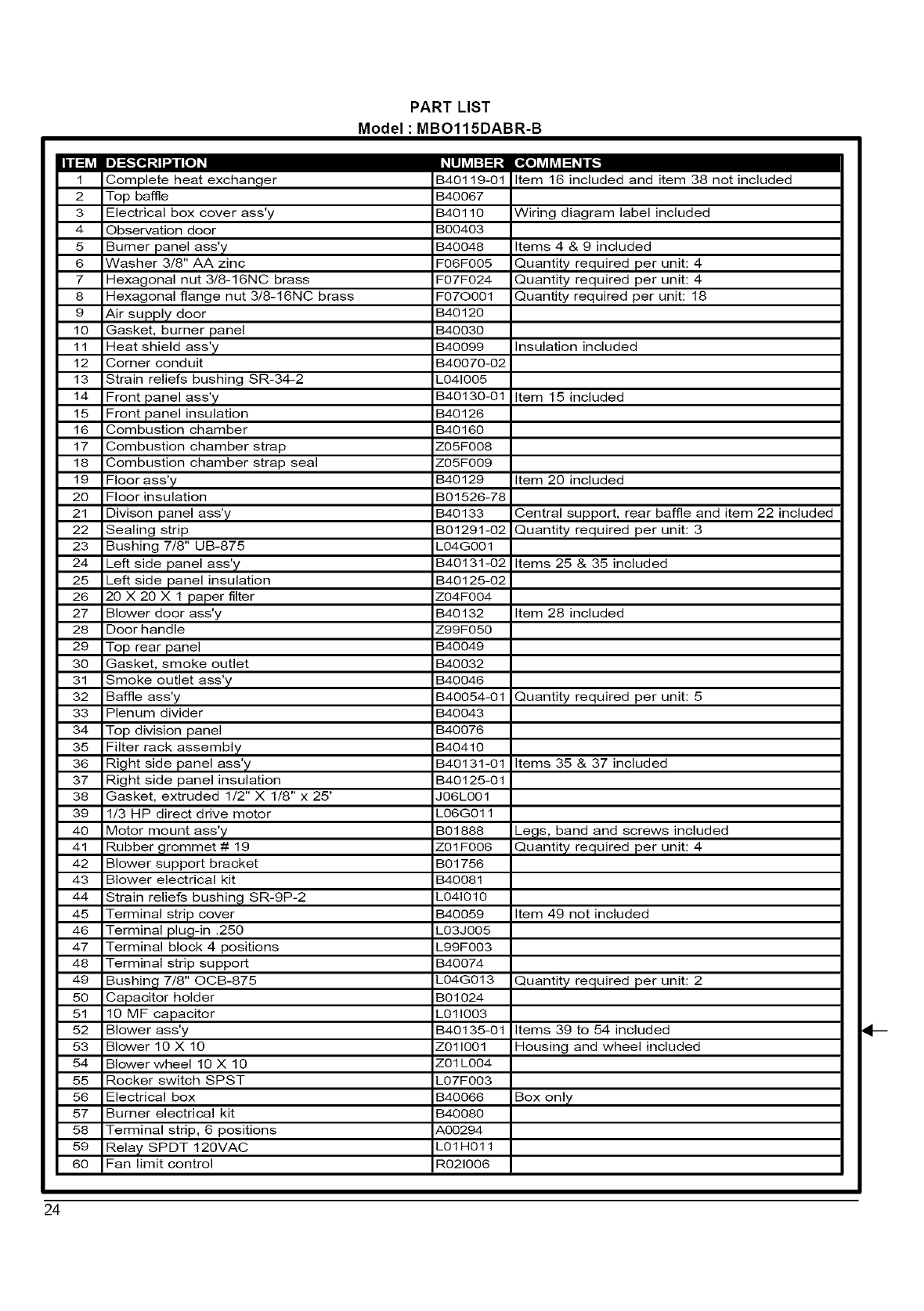
TABLE# 3.1
Techn ca spec f cat ons MBO115DABR-B MBOV115DABR-B MBOV115DABRU-B & MBOV115DBU-C
iNdiA _RFO_N
Firing rate USGPH
Input (BTU/h)
Heating capacity (BTU/h)
Maximum heating temperature rise (degr.F)
Low firing rate baffle
Static disc, model
Nozzle - 100 PSIG pump pressure (Delavan)
Combustion air adjustment (band /shutter)
Nozzle (Delavan)
Pump pressure (PSIG)
Combustion air adjustment (turbutator /damper)
0.65 0.90
91 000 126 000
74 000 103 000
0.75 I 0.85
105 000 119 000
85 000 97 000
55-85 Degr.F
YES
2 3/4 #3383
0.50 - 60W 0.60 - 60W 0.75 - 60W
165 155 145
0/2.25 1/2.75 2/3.75
Nozzle - 100 PSIG pump pressure (Delavan) 0.65 70W 0.75 70W 0.85 70W
EE RI_E _Y ............................................................................................................................................................................................................................................................................................................................................................................................................................................................................................................
Volts - Hertz - Phase 115 - 60 - 1
Operating voltage range 104 - 132
Rated current (Amp.) 11.4
Minimum ampacity for wiring sizing 12.8
Max. fuse size (Amps) 15
MED-LO I MED-Ht I HIGH HIGHMED-LO MED-HI HIGH HIGH
1/3 HP /4 speeds
10 X 10
Blower speed at 0.4" W.C. static pressure
Blower speed at 0.2" W.C. static pressure
Motor (HP) /number of speeds
Blower wheel size (in.)
Filter quantity and size 11) 20 X 20
TABLE # 4.1
Air delevery - CFM air filter
13
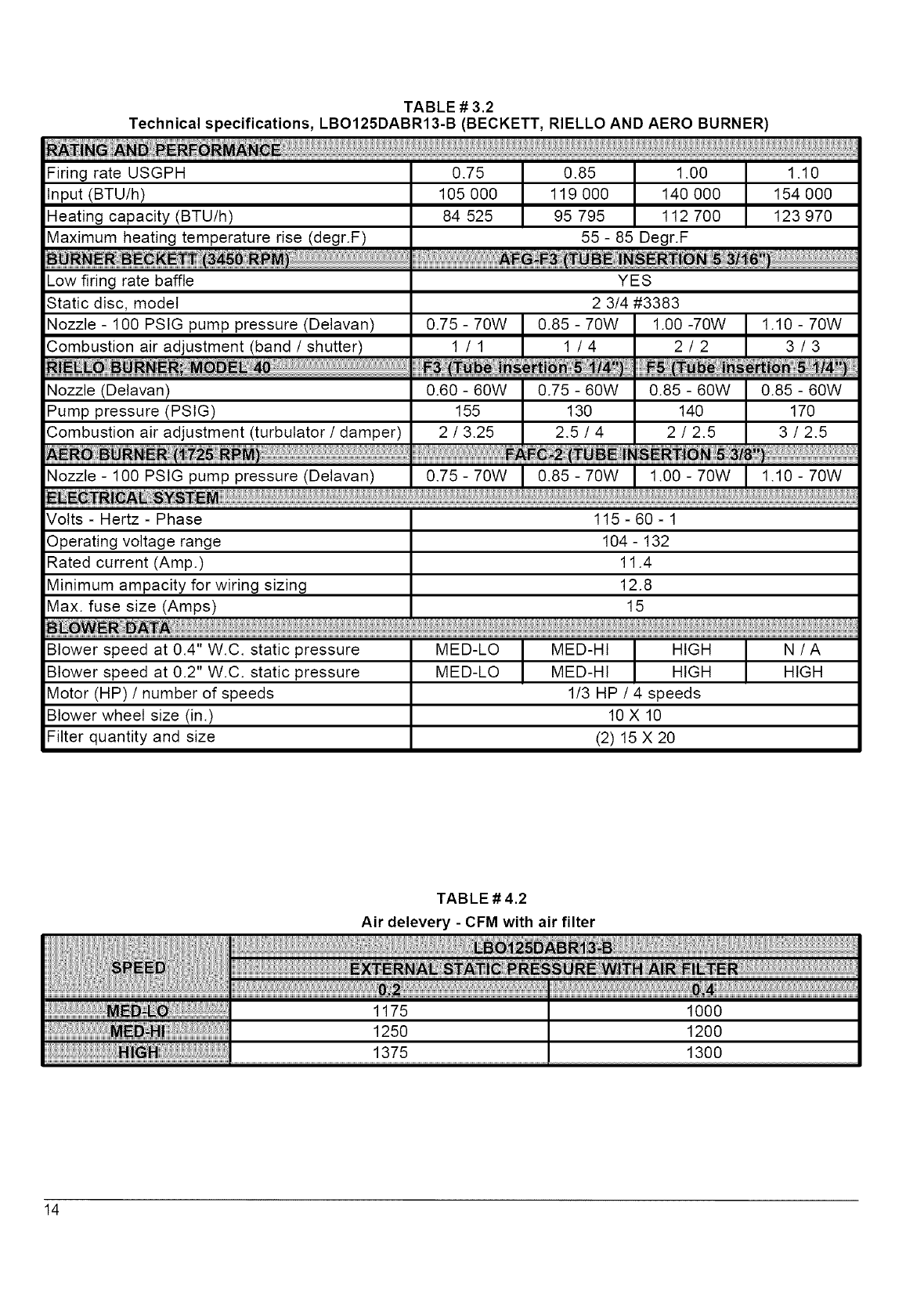
TABLE # 3.2
Technical specifications, LBO125DABR13-B (BECKETT, RIELLO AND AERO BURNER)
Firing rate USGPH
Input (BTU/h)
Heating capacity (BTU/h)
Maximum heating temperature rise (degr.F)
Low firing rate baffle
Static disc, model
Nozzle - 100 PSIG pump pressure (Delavan)
Combustion air adjustment (band /shutter)
URN_R;_ M_ 48'
0.75 1.10
105 000 154 000
84 525 123 970
0.85 1.00
119 000 140 000
95 795 112 700
55 - 85 Degr.F
0.75 - 70W
YES
2 3/4 #3383
0.85 - 70W
1/1 1/4
1.00 -70W
2/2
1.10 - 70W
3/3
;°zz!e:!00PS!Gpumppressure(Delavan) 0-75 - 70w I 0:85:7owI !00:70w I !!0: 7ow
Volts - Hertz - Phase 115 - 60 - 1
Operating voltage range 104 - 132
Rated current (Amp.) 11.4
Minimum ampacity for wiring sizing 12.8
Max. fuse size (Amps) 15
MED-LO N /A
MED-LO HIGH
MED-HI HIGH
MED-HI HIGH
1/3 HP /4 speeds
10 X 10
(2) 15 X 2O
Blower speed at 0.4" W.C. static pressure
Blower speed at 0.2" W.C. static pressure
Motor (HP) /number of speeds
Blower wheel size (in.)
Filter quantity and size
TABLE # 4.2
Air delevery - CFM with air filter
14
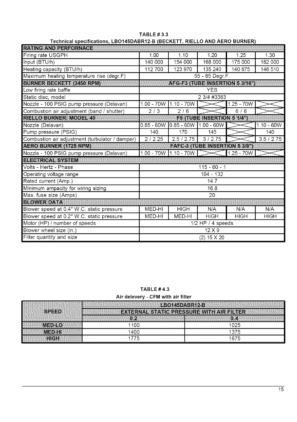
TABLE # 3.3
Technical specifications, LBO145DABR12-B (BECKETT, RIELLO AND AERO BURNER)
Firing rate USGPH 1.00 I 1.10 I 1.20 1.25 1.30
Input (BTU/h) 140 000 I 154 000 I 168 000 175 000 182 000
Heating capacity (BTU/h) 112 700 123 970 135 240 140 875 146 510
Maximum heating temperature rise (degr.F) 55 - 85 Degr.F.
Low firing rate baffle YES
Static disc, model 2 3/4 #3383
Nozzle - 100 PSIG pump pressure (Delavan) 1.00 - 70W 1.10 - 70W
Combustion air adjustment (band /shutter)
1.25 - 70W
2/3 2/6 6/6
Nozzle - 100 PSIG pump pressure (Delavan) 1.00 - 70W 1.10 - 70W 1.25 70W
Volts - Hertz - Phase 115 - 60 - 1
Operating voltage range 104 - 132
Rated current (Amp.) 14.7
Minimum ampacity for wiring sizing 16.8
Max. fuse size (Amps) 20
MED-HI } HIGH } N/A N/A N/A
MED-HI MED-HI HIGH HIGH HIGH
1/2 HP /4 speeds
12X9
Blower speed at 0.4" W.C. static pressure
Blower speed at 0.2" W.C. static pressure
Motor (HP) /number of speeds
Blower wheel size (in.)
Filter quantity and size (2) 15 X 20
TABLE # 4.3
Air delevery - CFM with air filter
15
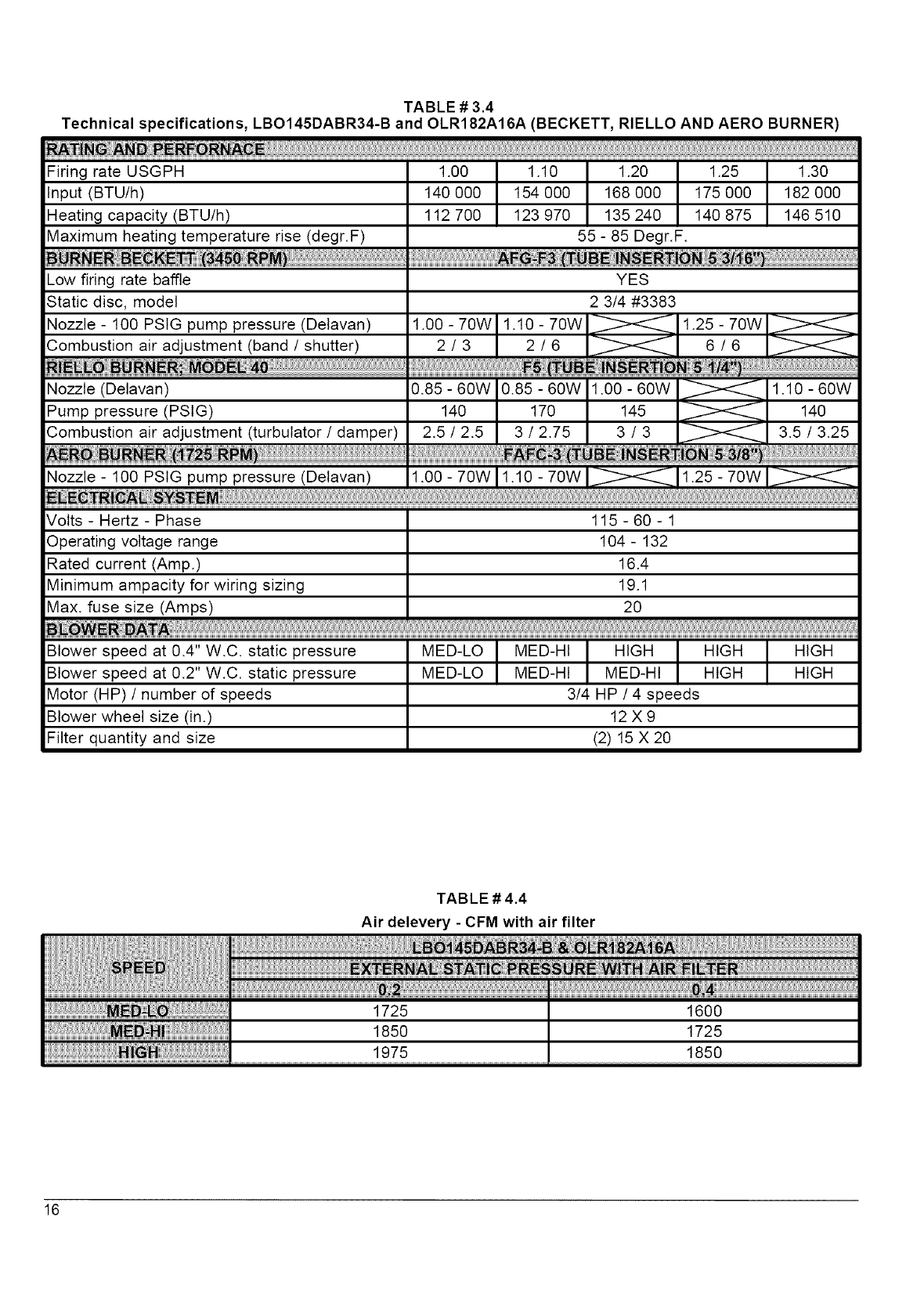
Volts- Hertz- Phase 115- 60- 1
Operatingvoltagerange 104- 132
Ratedcurrent(Amp.) 16.4
Minimumampacityfor wiringsizing 19.1
Max.fusesize (Amps) 20
MED-LO HIGH HIGH
MED-LO HIGH HIGH
Blowerspeedat 0.4"W.C.staticpressure
Blowerspeedat 0.2"W.C.staticpressure
Motor(HP)/number of speeds
Blower wheel size (in.)
Filter quantity and size
MED-Ht HIGH
MED-HI MED-HI
3/4 HP /4 speeds
12X9
(2) 15 X 2O
TABLE # 4.4
Air delevery - CFM with air filter
16
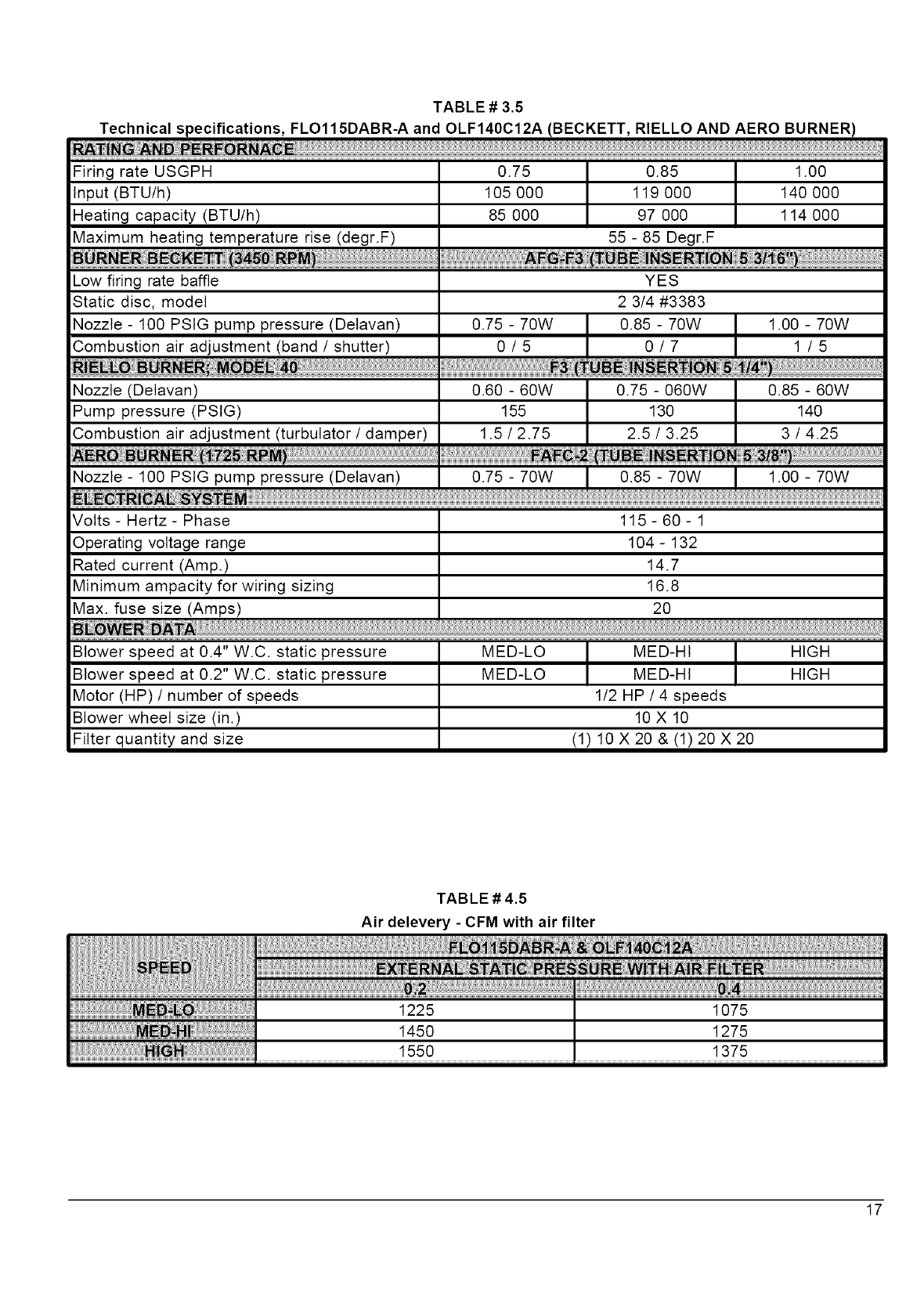
TABLE # 3.5
Technical specifications, FLO115DABR-A and OLF140C12A (BECKETT, RIELLO AND AERO BURNER)
Firing rate USGPH 0.75 0.85 1.00
Input (BTU/h) 105 000 119 000 140 000
Heating capacity (BTU/h) 85 000 97 000 114 000
Maximum heating temperature rise (degr.F) 55 - 85 Degr.F
Low firing rate baffle YES
Static disc, model 2 3/4 #3383
Nozzle (Delavan)
Noz_e:!00Ps!Gpumpp:essu:e!De!a_an! 0_75-70w I 0_85-70w I !00-70w
Volts - Hertz - Phase 115 - 60 - 1
Operating voltage range 104 - 132
Rated current (Amp.) 14.7
Minimum ampacity for wiring sizing 16.8
Max. fuse size (Amps) 20
MED-LO HIGH
MED-LO HIGH
Blower speed at 0.4" W.C. static pressure
Blower speed at 0.2" W.C. static pressure
Motor (HP) /number of speeds
Blower wheel size (in.)
Filter quantity and size
MED-Ht
MED-HI
1/2 HP /4 speeds
10 X 10
(1) 10 X 20 & (1) 20 X 20
TABLE # 4.5
Air delevery - CFM with air filter
17
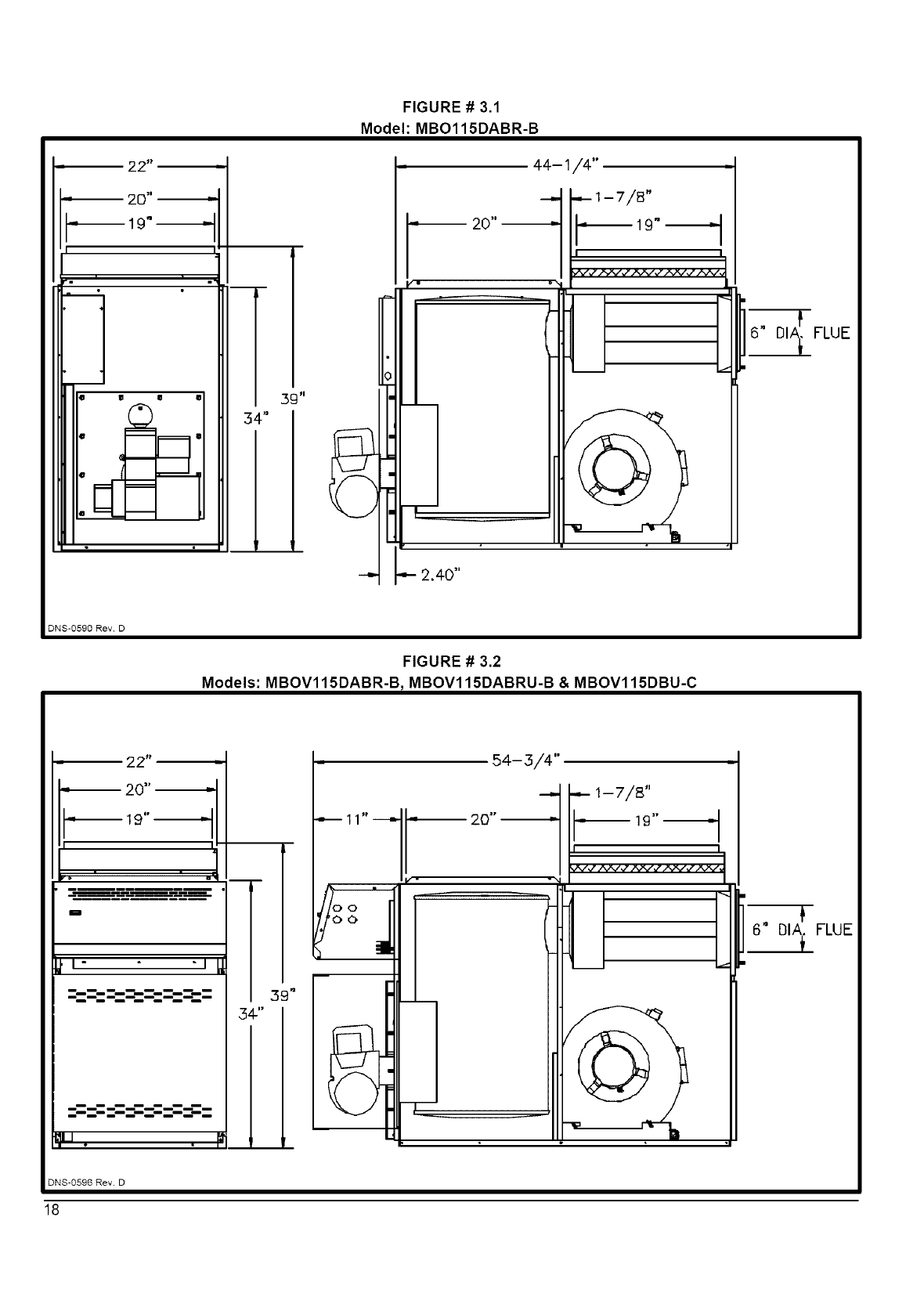
FIGURE# 3.1
Model: MBO115DABR-B
44-1/4"
DNS-0590 Rev. D
FIGURE # 3.2
Models: MBOV115DABR-B tMBOV115DABRU-B & MBOV115DBU-C
- 22" -
20" .'_
mB
31t°
34-"
T
LII
54-3/4"
1--7/8".
"_.--27r-_..
6" DIA_ FLUE
DNS-0596 Rev. D
18
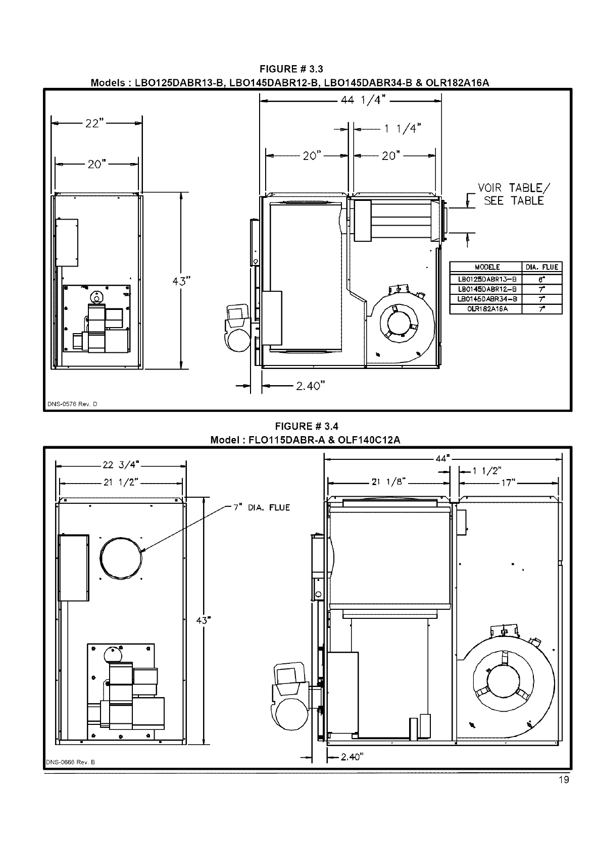
FIGURE # 3.3
Models : LBO125DABR13-B tLBO145DABR12-B tLBO145DABR34-B & OLR182A16A
,,,, 44 1/4" -
DNS-0576 Rev. D
VOIR TABLE/
_- SEE TABLE
---F
MOOB.E
LB0125DABR13--B
LB014.=iDABR1?_-B
LB014-SDABR34-B
0_t8_16A
22 3/4"
21 1/2"
@ @ QI
DNS-0666 Rev B
/
43"
FIGURE # 3.4
Model : FLO115DABR-A & OLF140C12A
fT" DIA, FLUE
21 1/8"
44"
--I 1/2"
= 17"I
,,
19
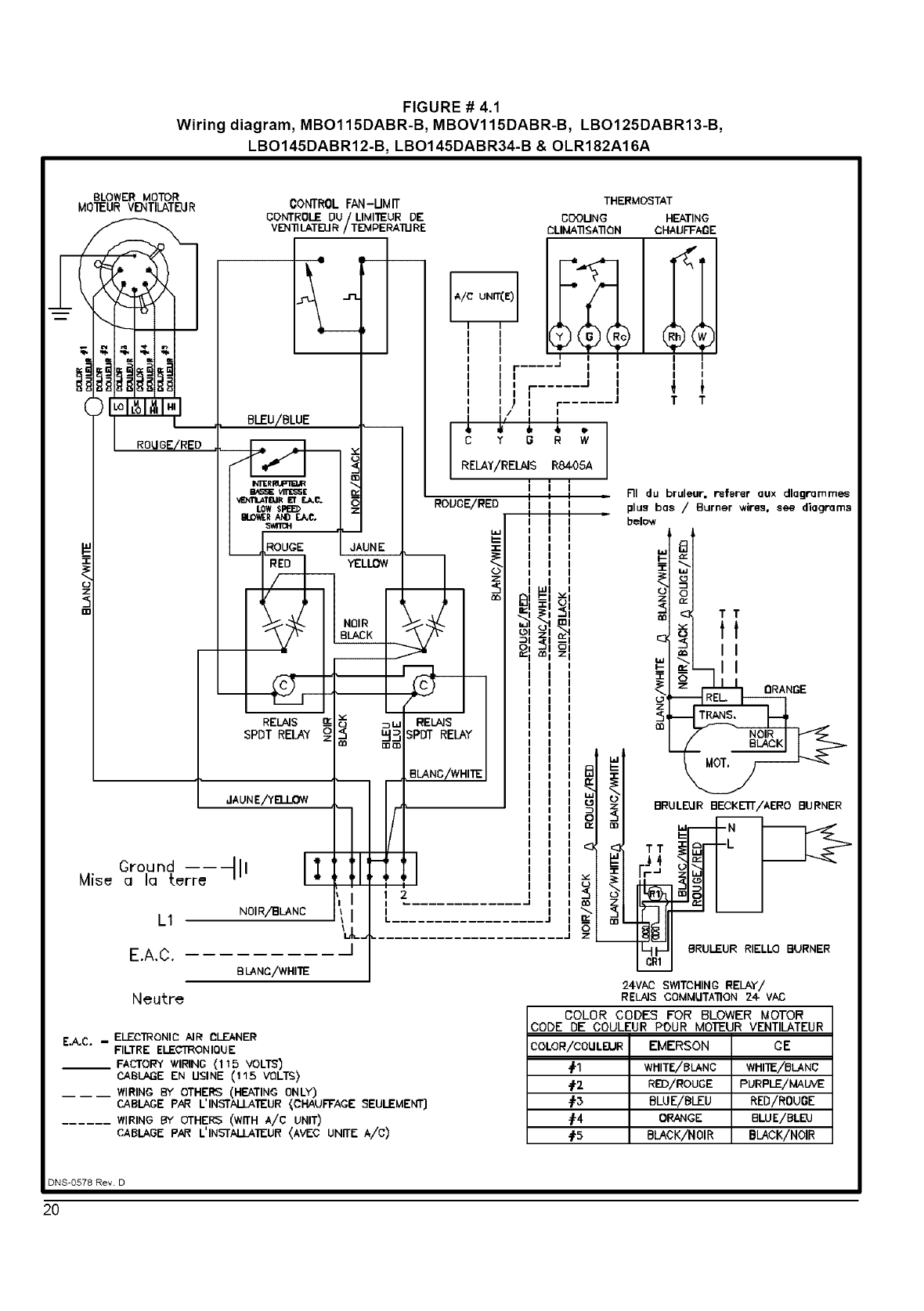
FIGURE # 4.1
Wiring diagram, MBO115DABR-B, M BOV115DABR-B, LBO125DABR13-B,
LBO145DABR12-B, LBO145DABR34-B & OLR182A16A
BLOWER MOTOR
MO'IEUR VI_TILATEU R
ROUGE/RED .
Ground ---- -
Mise a la terre
CONTROL FAN-UMIT
GDNTROLE DU/LIMITEUR DE
VE_ll LATELIR /TE3MPERA'il.I RE
, BLEU/BL
EIJ_V_RANDF.._C,
SWITCH
SPDT RELAY z =
JAUNEiYR I OW __
tl, l :it: ,
L1
E.A,C.
A/C UNIT(E)
ROUOE/RED
THERMOSTAT
CDOUNG HEATING
PLIIdA'n_;A'n_]N CHAIJFFAGE
r- .... J J i
I I I
I r....... J I
I I I
I
CY G RW
RELAY/RELAIS R84-O5A
i i i
I i I
I I I
NOIRiBLANG ]1
]
BLANC/WHITE
=_I=,
_1 I 1 2
I
I
I
I I
I i
TT
Neutre
E.A,C. - ELECTRONIC AIR I_LF-.ANER
FILTRE ELEC'[RON IQU E
__ FACTORY WIRING (115 VOLTS)
CABLA_E EN USINE (115 VI3LT_)
____ WIRING BY OTHERS (HEATING ONLY)
CABLAGE PAR L'INSTALLATEUR {CHAUFTAGE SEULEMENT]
...... WIRING BY OTHERS (WITH A/C UNIT)
CABLAGE PAR L'INSTALLA'IEUR (AVEC UNITE A/C)
L..................
RI du bruleur, referer aux dlagrammee
plus bas /Burner wires, see diagrams
bek_v
TT
.__J_I It
"I _I _
__.1_t t
_i_ NP'E
,gOT.
_1 BRU,_RBB_KLL'n'/AERO BURNER
_Ir,: _1_1 I
BRULEUR RIELLO BURNER
24VAC SWITCHING RELAY/
RELAI5 COMMUTA'nON 24- VAC
COLOR CODES FOR BLOWER MOTOR
CODE DE COULEUR POUR MOTEUR VENTILATEUR
COLOR/¢OULBJR EMERSON CE
fl WI'IITE/BLA,NC WHITE/BLANC
-#'2 RED/ROUGE PURPLE/MAUVE
_3 BLUE/BLEU RED/ROUGE
#-4 ORANGE BLUE/BLEU
-f5 BLACK/NOIR BLACK/NOIR
DNS-0578 Rev. D
2O
BLOWER MOTOR
RD
1
z
3
4
TIME DELAY RELAY
30 TO 120 SEC, -J
8O
BK
MNN POWER
SwIIG H
OU'ILFT
(;round -----
L1
E,A.C,
Neutral
DNS-0593 Rev. B
FIGURE # 4.2
Wiring diagram, MBOV115DABRU-B & MBOV115DBU-C
CONTROL
FAN - UMIT
LOW SPEED
BLOWERAND E.A.C.
SWITCH
THERMOSTAT
COOLING HEATING
I
I
r I
I r- .......... ..i
I I
I
,[
RELAY RB4OSA
I
I
I
I
I
SPDT SPDT
RELAY RI!]_kY
WH
BK
OR
WH
WH
EL
8K
PL
WH
YL
WH
I
I
I
4
I L...........
L. ................
..................... a
I
WH
jINDICATOR
LIGHT
E.A.O. :ELECTRONICAIR CLEANER
-- FACTORY WIRING (115 VOLTS)
------ WIRING BY OTHERS (HEATING ONLY)
..... WIRING BY OTHERS (WITH A!C UNIT)
21
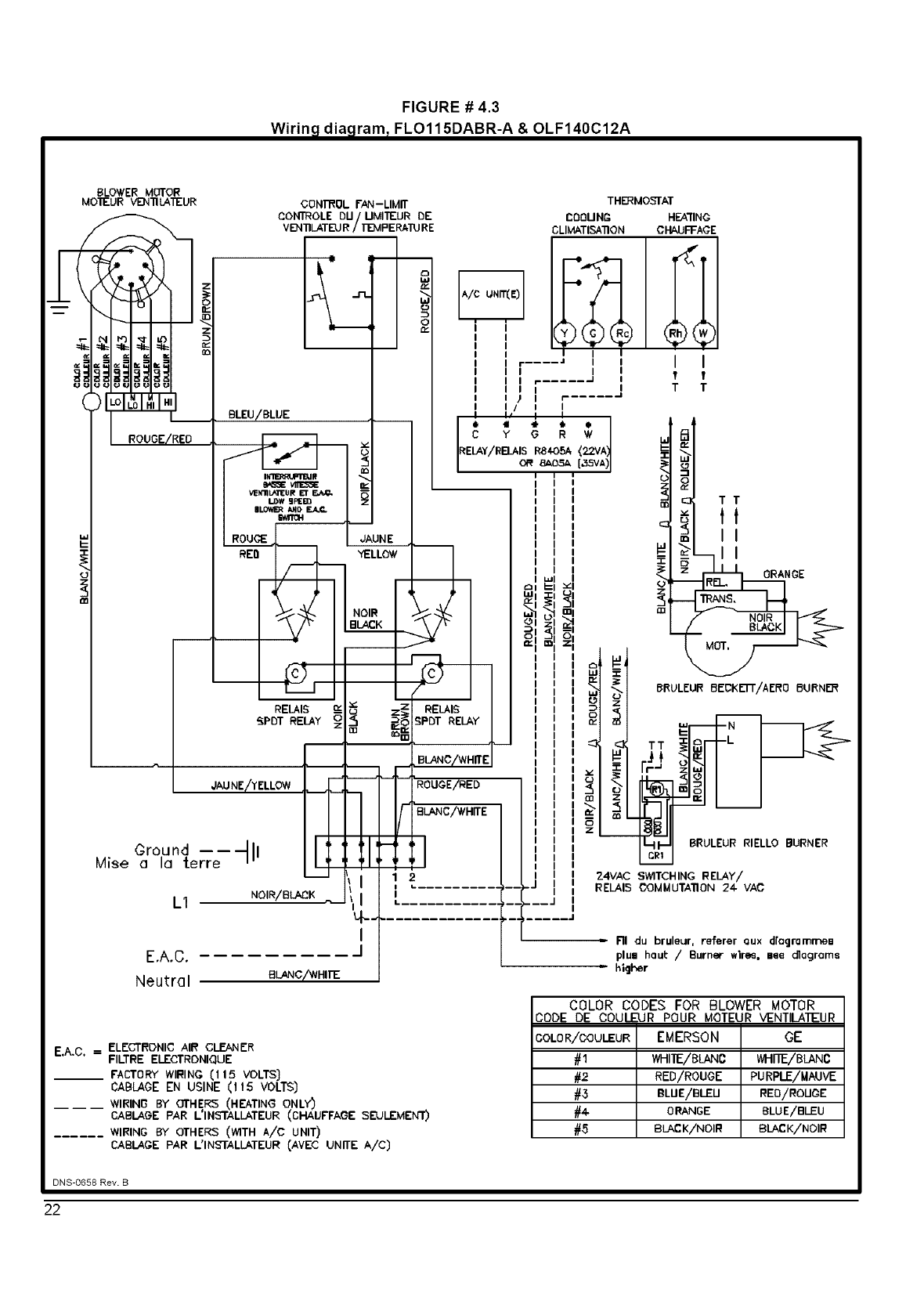
FIGURE # 4.3
Wirina,rdiaaramt,rFLO115DABR-A & OLF140C12A
/
BLOWER_4OTOR
MOTEUR VENTILATEUR
(
v_
CONTROL FAN-LIMIT
CONTROLE DU/UMITEUR DE
VB411LATEUR/T'E_PERATU RE
e
JkUNE ,
"YELLOW
RELAIS {z
_PDT RELAY z_
,,'AUNE/','ELLOW
Croood Ill
Mise a la terre
LI NOIR/BLACK
E,A.C.
Neutral BLANC/_NHIE
I
J
THERMOS'TAT
COOU NP- HEA'rlNC
CLIMATISA'ilON CI-_UFFACE
=RI du bruleur, referer aux dfagromrnen
plu= haul: /Burner wlre_, nee diagrams
=higher
E.A.C. = ELECTRONIC AIR CLEANER
FILTRE ELECTRONIQUE
__ FACTORY WIRING (1 15 VOLTS]
CABLAGE EN USINE (1 t5 VOLTS)
____ WIRING BY OTHERS (HEATING ONLY)
CABLAGE PAR L'INSTALL&TEUR (CHAUFFAGE SEULEMENT)
...... WIRING BY OTHERS (WITH A/C UNIT)
CABLAGE PAR L'INSTALLATEUR CAVE(:; UNITE A/C)
COLOR CODES FOR BLOWER MOTOR
CODE DE COULEUR POUR MOTEUR VENTILATEUR
GOLOR/COULEUR EMERSON GE
#1 WHITE/BLAN0 WHI'E/BLANC
#2 RED/ROUGE PURPLE/MAUVE
#3 BLUE/BLEU REB/ROUCE
#4- ORANGE BLUE/BLEU
#5 BLACK/NOIR BLAEK/NOIR
DNS-0658 Rev. B
22
0
z
co
m
DETAIL
DETAIL "B"
I
....-.---.-'1
t\.
o
D.
r-
O0
;o
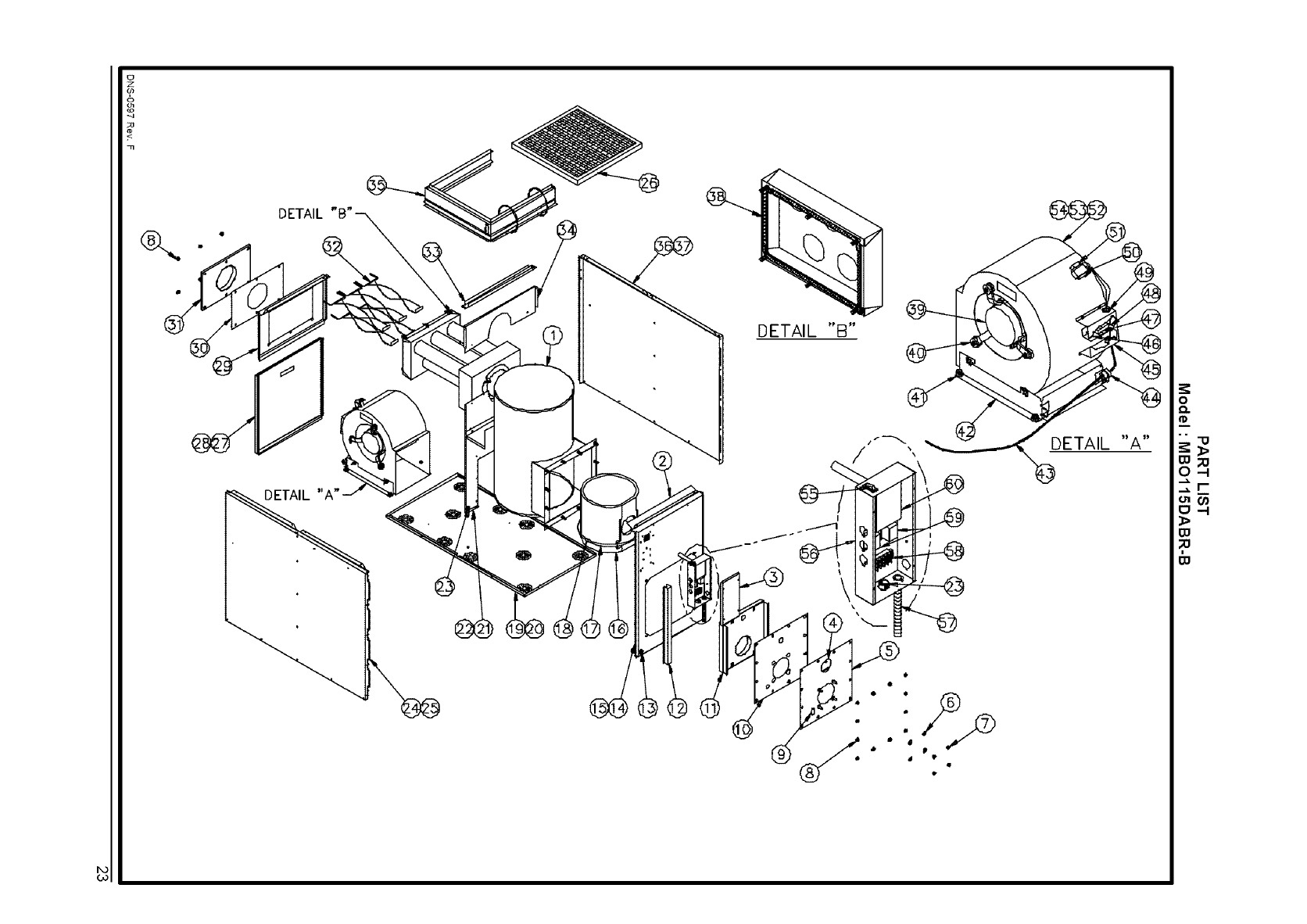
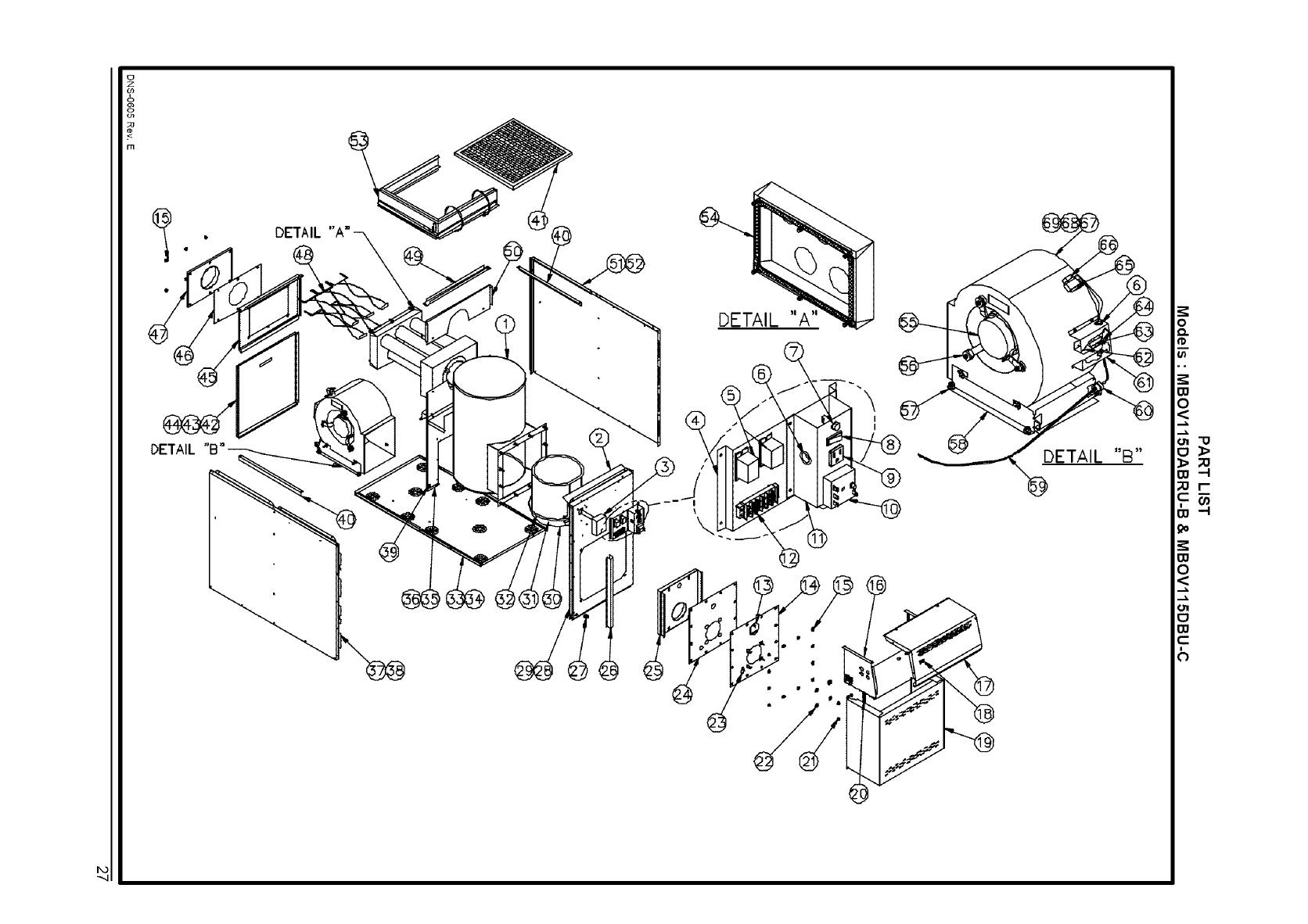
PART LIST
Model: MBO115DABR-B
)lete heat
2 Top 13affle
3 Electrical box cover ass'y
4 Observation door
5 Burner panel ass'y
6 Washer 3/8" AA zinc
7 Hexagonal nut 3/8-16NC brass
8 Hexagonal flange nut 3/8-16NC brass
9 Air supply door
10 Gasket, burner panel
11 Heat shield ass'y
12 Corner conduit
13 Strain reliefs bushing SR-34-2
14 Front panel ass'y
15 Front panel insulation
16 Combustion chamber
17 Combustion chamber strap
18 Combustion chamber strap seal
19 Floor ass'y
20 Floor insulation
21 Divison panel ass'y
22 Sealing strip
23 Bushing 7/8" UB-875
24 Left side panel ass'y
25 Left side panel insulation
26 20 X 20 X 1 paper filter
27 Blower door ass'y
28 Door handle
29 Top rear panel
30 Gasket, smoke outlet
31 Smoke outlet ass'y
32 Baffle ass'y
33 Plenum divider
34 Top division panel
35 Filter rack assembly
36 Right side panel ass'y
37 Right side panel insulation
38 Gasket, extruded 1/2" X 1/8" x 25'
39 1/3 HP direct drive motor
40 Motor mount ass'y
41 Rubber grommet # 19
42 Blower support bracket
43 Blower electrical kit
44 Strain reliefs bushing SR-9P-2
45 Terminal strip cover
46 Terminal plug-in .250
47 Terminal block 4 positions
48 Terminal strip support
49 Bushing 7/8" OCB-875
50 Capacitor holder
51 10 MF capacitor
52 Blower ass'y
53 Blower 10 X 10
54 Blower wheel 10 X 10
55 Rocker switch SPST
56 Electrical box
57 Burner electrical kit
58 Terminal strip, 6 positions
59 Relay SPDT 120VAC
60 Fan limit control
B40067
B40110
B00403
B40048
F06F005
F07F024
F070001
B40120
B40030
B40099
B40070-02
L041005
B40119-01 Item 16 included and item 38 not included
Wiring diagram label included
Items 4 & 9 included
Quantity required per unit: 4
Quantity required per unit: 4
Quantity required per unit: 18
Insulation included
B40130-01 Item 15 included
B40126
B40160
Z05F008
Z05F009
B40129 Item 20included
B01526-78
B40133 Central support, rear baffle and item 22included
B01291-02 Quantity required per unit: 3
L04G001
B40131-02 Items 25 & 35 included
B40125-02
Z04F004
B40132 Item 28 included
Z99F050
B40049
B40032
B40046
B40054-01 Quantity required per unit: 5
B40043
B40076
B40410
B40131-01 Items 35 & 37 included
B40125-01
J06L001
L06G011
B01888
Z01F006
B01756
B40081
L041010
B40059 Item 49 notincluded
L03J005
L99F003
B40074
L04G013 Quantity required per unit: 2
B01024
L011003
B40135-01 Items 39 to 54 included
Z011001 Housing and wheelincluded
Z01L004
L07F003
B40066 Box only
B40080
A00294
L01H011
R021006
Legs, band and screws included
Quantity required per unit: 4
24
U
z
co
rn
DETAIL
DETAIL "A"
@
DETAIL "A"
I
I
/®
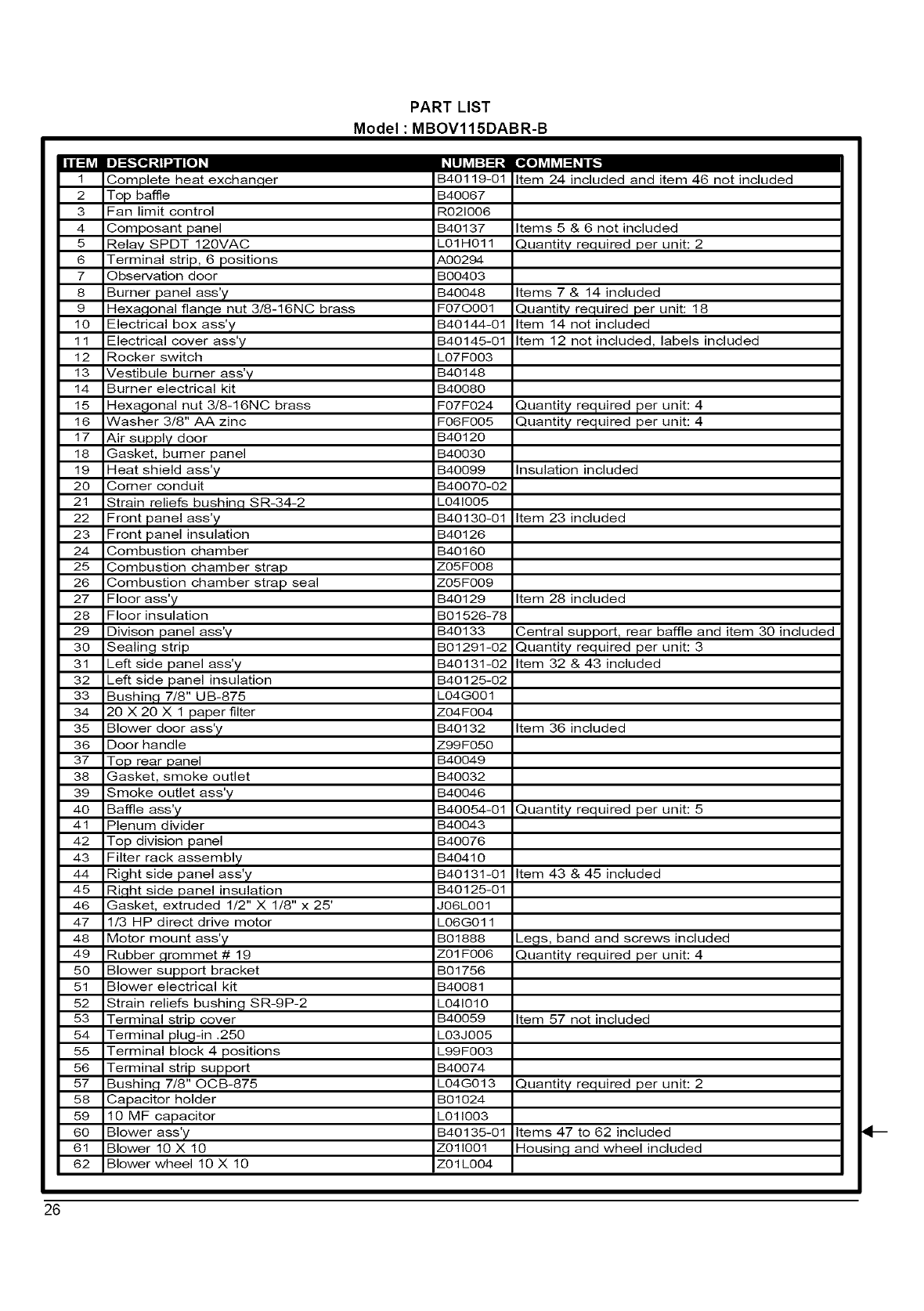
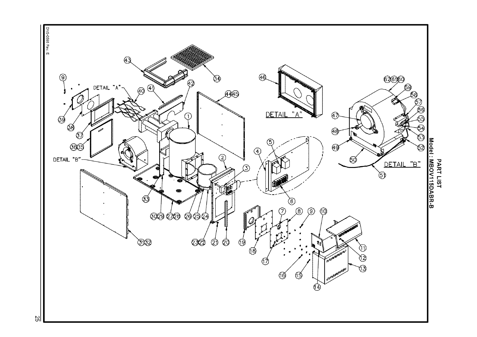
PART LIST
Model: MBOV115DABR-B
31ete heat exchan(
2 Top 13affle
3 Fan limit control
4 Composant panel
5 Relay SPDT 120VAC
6 Terminal strip, 6 positions
7 Observation door
8 Burner panel ass'y
9 Hexagonal flan,qe nut 3/8-16NC brass
10 Electrical box ass'y
11 Electrical cover ass':7
12 Rocker switch
13 Vestibule burner ass'y
14 Burner electrical kit
15 Hexagonal nut 3/8-16NC brass
16 Washer 3/8" AA zinc
17 Air supply door
18 Gasket, burner panel
19 Heat shield ass'y
20 Corner conduit
21 Strain reliefs bushin,q SR-34-2
22 Front panel ass'y
23 Front panel insulation
24 Combustion chamber
25 Combustion chamber strap
26 Combustion chamber strap seal
27 Floor ass'y
28 Floor insulation
29 Divison panel ass'y
30 Sealing strip
31 Left side panel ass'y
32 Left side panel insulation
33 Bushin,q 7/8" UB-875
34 20 X 20 X 1 paper filter
35 Blower door ass'y
36 Door handle
37 Top rear panel
38 Gasket, smoke outlet
39 Smoke outlet ass'y
40 Baffle ass'y
41 Plenum divider
42 Top division panel
43 Filter rack assembly
44 Right side panel ass'y
45 Ri,qht side panel insulation
46 Gasket, extruded 1/2" X 1/8" x 25'
47 1/3 HP direct drive motor
48 Motor mount ass'y
49 Rubber ,qrommet # 19
50 Blower support bracket
51 Blower electrical kit
52 Strain reliefs bushing SR-9P-2
53 Terminal strip cover
54 Terminal plug-in .250
55 Terminal block 4 positions
56 Terminal strip support
57 Bushing 7/8" OCB-875
58 Capacitor holder
59 10 MF capacitor
60 Blower ass'y
61 Blower 10 X 10
62 Blower wheel 10 X 10
B40119-01
B40067
R021006
B40137
L01H011
A00294
B00403
B40048
F070001
B40144-01
B40145-01
L07F003
B40148
B40080
F07F024
F06F005
B40120
B40030
B40099
B40070-02
L041005
B40130-01
B40126
B40160
ZO5FO08
ZO5FO09
B40129
B01526-78
Item 24 included and item 46 not included
Items 5 & 6 not included
Quantity required per unit: 2
Items 7 & 14 included
Quantity required per unit: 18
Item 14 not included
Item 12 not included, labels included
Quantity required per unit: 4
Quantity required per unit: 4
Insulation included
Item 23 included
Item 28 included
B40133 Central support Trear baffle and item 30 included
B01291-02 Quantity required per unit: 3
B40131-02 Item 32 & 43 included
B40125-02
L04G001
Z04F004
B40132
Z99F050
B40049
B40032
B40046
B40054-01
B40043
B40076
B40410
B40131-01
B40125-01
J06L001
L06G011
B01888
Z01F006
B01756
B40081
L041010
B40059
L03J005
L99F003
B40074
L04G013
B01024
L011003
B40135-01
Z011001
Z01L004
Item 36 included
Quantity required per unit: 5
Item 43 & 45 included
Legs, band and screws included
Quantity required per unit: 4
Item 57 not included
Quantity required per unit: 2
Items 47 to 62 included
Housin,q and wheel included
26
U
z
co
g
111
DETAIL
DETAIL "A"
\\
DETAIL "A"
@DETAIL "B"
<.
F_
IZI -I
<.
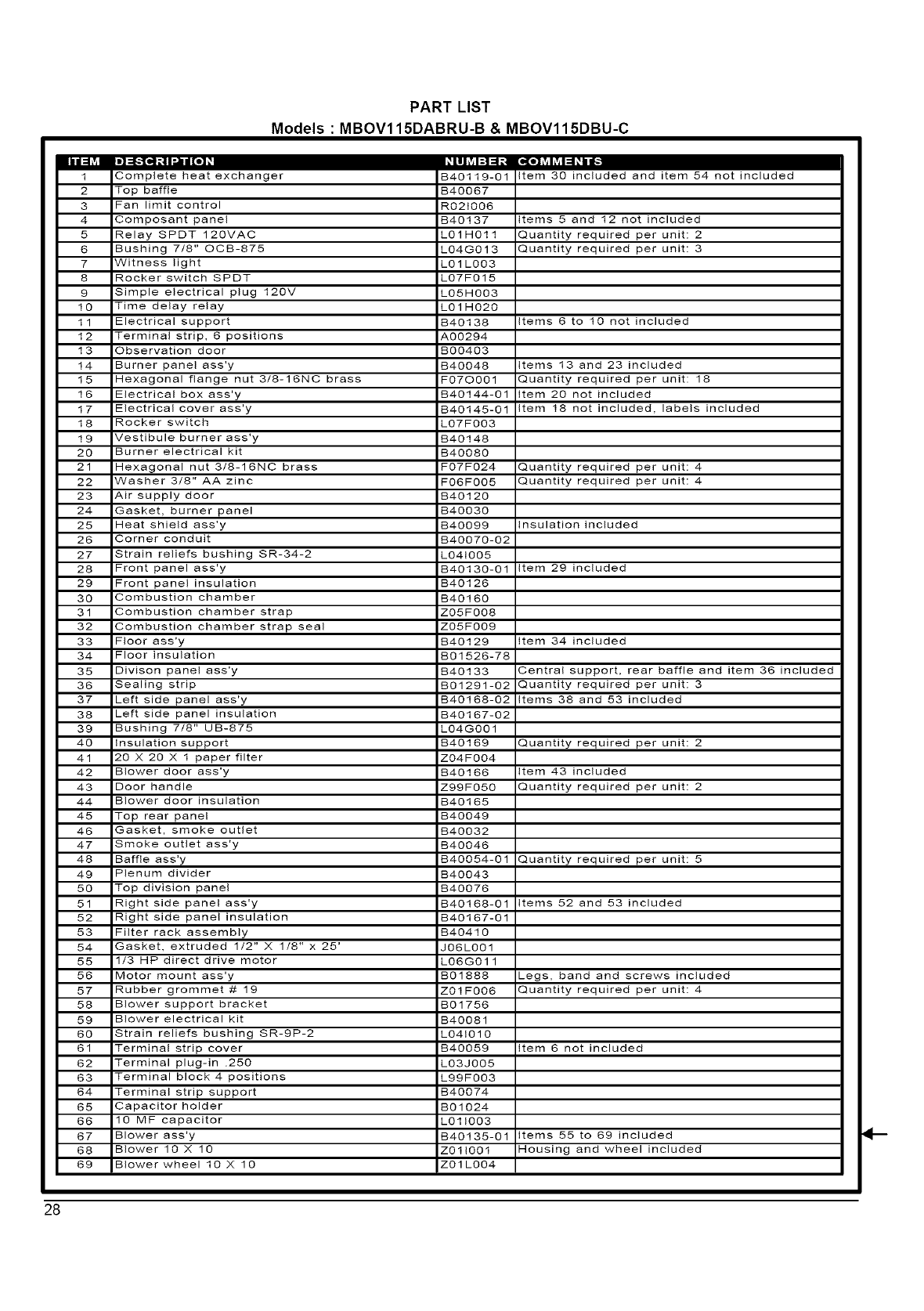
PART LIST
Models : MBOV115DABRU-B & MBOV115DBU-C
Complete heat exchanger
2 Top baffle
3 Fan limit control
4 Composant panel
5 Relay SPDT 120VAC
6 Bushing 7/8" OOB-875
7 Witness light
8 Rocker switch SPDT
9 Simple electrical plug 120V
10 Time delay relay
11 Electrical support
12 Terminal strip, 6 positions
13 Observation door
14 Burner panel ass'y
15 Hexagonal flange nut 3/8-16NC brass
16 Electrical box ass'y
17 Electrical cover ass'y
18 Rocker switch
19 Vestibule burner ass'y
20 Burner electrical kit
21 Hexagonal nut 3/8-16NC brass
22 Washer 3/8" AA zinc
23 Air supply door
24 Gasket, burner panel
25 Heat shield ass'y
26 Corner conduit
27 Strain reliefs bushing SR-34-2
28 Front panel ass'y
29 Front panel insulation
30 Combustion chamber
31 Combustion chamber strap
32 Combustion chamber strap seal
33 Floor ass'y
34 Floor insulation
35 Divison panel ass'y
36 Sealing strip
37 Left side panel ass'y
38 Left side panel insulation
39 Bushing 7/8" UB-875
40 Insulation support
41 20 X 20 X 1 paper filter
42 Blower door ass'y
43 Door handle
44 Blower door insulation
45 Top rear panel
46 Gasket, smoke outlet
47 Smoke outlet ass'y
48 Baffle ass'y
49 Plenum divider
50 Top division panel
51 Right side panel ass'y
52 Right side panel insulation
53 Filter rack assembly
54 Gasket, extruded 1/2" X 1/8" x 25'
55 1/3 HP direct drive motor
56 Motor mount ass'y
57 Rubber grommet # 19
58 Blower support bracket
59 Blower electrical kit
60 Strain reliefs bushing SR-9P-2
61 Terminal strip cover
62 Terminal plug-in .250
63 Terminal block 4 positions
64 Terminal strip support
65 Capacitor holder
66 O MF capacitor
67 Blower ass'y
68 Blower 10 X 10
69 Blower wheel 10 X 10
B40119-01 Item 30 included and item 54 not included
B40067
R0210O6
B40137 Items 5 and 12 not included
LOIHO11 Quantity required per unit: 2
LO4G013 Quantity required per unit: 3
LO 1L003
LO7F015
LO5HO03
LOl HO20
B40138 Items 6 to 10 not included
A00294
BOO403
B40048 Items 13 and 23 included
F07OO01 Quantity required per unit: 18
B40144-01 Item 20 not included
B40145-01 Item 18 not included, labels included
LO7F0O3
B40148
B4O08O
F07FO24 Quantity required per unit: 4
F06FO05 Quantity required per unit: 4
B40120
B4O03O
B40099 Insulation included
B40070-02
LO410O5
B40130-01 Item 29 included
B40126
B40160
Z05FO08
Z05FO09
B40129 Item 34 included
B01526-78
B40133 Central support, rear baffle and item 36 included
B01291-02 Quantity required per unit: 3
B40188-02 Items 38 and 53 included
B40167-02
LO4G0Ol
B40189 Quantity required per unit: 2
Z04FO04
B40166 Item 43 included
Z99FO50 Quantity required per unit: 2
B40165
B40049
B40032
B40046
B40054-01 Quantity required per unit: 5
B40043
B40076
B40168-01 Items 52 and 53 included
B40187-01
B40410
J06L0Ol
LO6G011
B01888
Z01 FO06
BO 1756
B40081
LO41010
B40059 Item 6 not included
LO3J0O5
L99F003
B40074
BO 1024
LO11003
B40135-01 Items 55 to 69 included
ZOllO01 Housing and wheel included
Z01 L0O4
Legs, band and screws included
Quantity required per unit: 4
4--
28
0
z
<
0
DETAIL
DETAIL
DETAIL "B"
O
D.
O@
O@
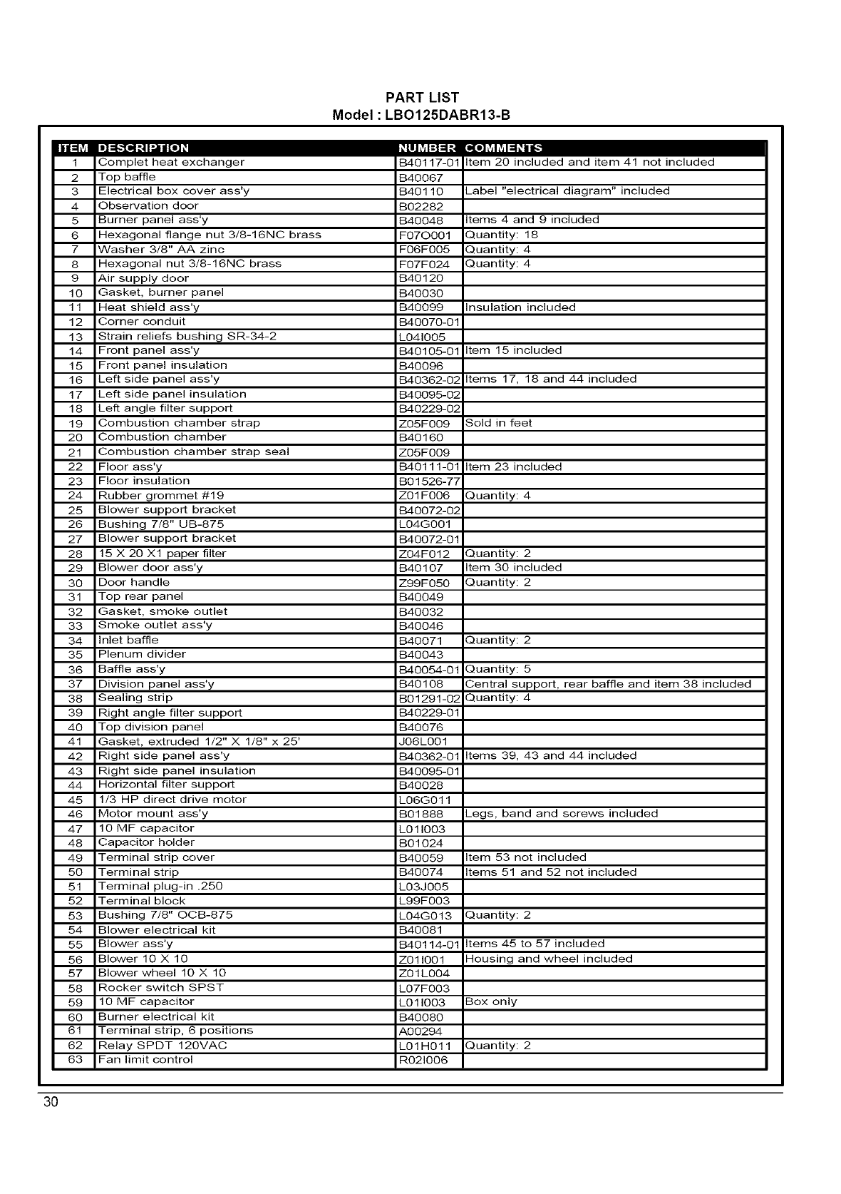
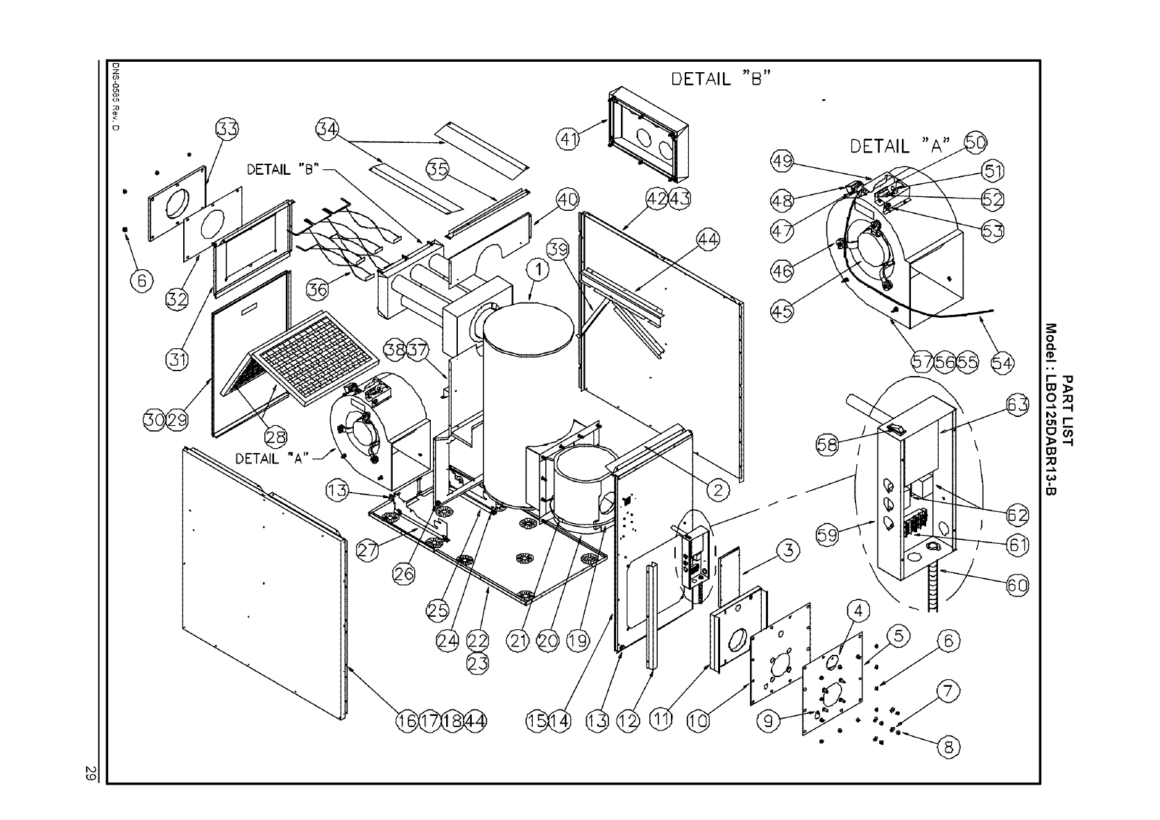
PART LIST
Model: LBO125DABR13-B
Complet heat exchanger B40117-01 Item 20 included and item 41 not included
2 Top baffle B40067
3 Electrical box cover ass'y B40110 _abel "electrical diagram" included
4 Observation door B02282
5 Burner panel ass'y B40048 Items 4 and 9 included
6 Hexagonal flange nut 3/8-16N0 brass F070001 _uantity: 18
7 Washer 3/8" AA zinc F06F005 _uantity: 4
8 Hexagonal nut 3/8-16N0 brass F07F024 _uantity: 4
9 Air supply door B40120
10 Gasket, burner panel B40030
11 Meat shield ass'y B40099 Insulation included
12 Corner conduit B40070-01
13 Strain reliefs bushing 8R-34-2 L041005
14 Front panel ass'y B40105-01 Item 15 included
15 Front panel insulation B40096
16 Left side panel ass'y B40362-02 Items 17, 18 and 44 included
17 Left side panel insulation B40095-02
18 Left angle filter support B40229-02
19 Combustion chamber strap Z05F009 Sold in feet
20 Combustion chamber B40160
21 Combustion chamber strap seal Z05F009
22 Floor ass'y B40111-01 Item 23 included
23 Floor insulation B01526-77
24 Rubber grommet #19 Z01F006 _uantity: 4
25 Blower support bracket B40072-02
26 Bushing 7/8" UB-875 L04G001
27 Blower support bracket B40072-01
28 15 X 20 X1 paper filter Z04F012 :_uantity: 2
29 Blower door ass'y B40107 Item 30 included
30 Door handle Z99F050 _uantity: 2
31 Top rear panel B40049
32 Gasket, smoke outlet B40032
33 Smoke outlet ass'y B40046
34 Inlet baffle B40071 _uantity: 2
35 Plenum divider B40043
36 Baffle ass'y B40054-01 _uantity: 5
37 Division panel ass'y B40108 Dentral support, rear baffle and item 38 included
38 Sealing strip B01291-02 _uantity: 4
39 Right angle filter support B40229-01
40 Top division panel B40076
41 Gasket, extruded 1/2" X 1/8" x 25' J06L001
42 Right side panel ass'y B40362-01 Items 39, 43 and 44 included
43 Right side panel insulation B40095-01
44 Horizontal filter support B40028
45 1/3 HP direct drive motor L06G011
46 Motor mount ass'y B01888 _egs, band and screws included
47 10 MF capacitor L011003
48 Capacitor holder B01024
49 Terminal strip cover B40059 Item 53 not included
50 Terminal strip B40074 Items 51 and 52 not included
51 Terminal plug-in .250 L03J005
52 Terminal block L99F003
53 Bushing 7/8" OOB-875 L04G013 _uantity: 2
54 Blower electrical kit B40081
55 Blower ass'y B40114-01 Items 45 to 57 included
56 Blower 10 X 10 Z011001 -lousing and wheel included
57 Blower wheel 10 X 10 Z01L004
58 Rocker switch SPST L07F003
59 10 MF capacitor L011003 Box only
60 Burner electrical kit B40080
61 Terminal strip, 6 positions A00294
62 Relay SPDT 120MAC L01H011 _uantity: 2
63 Fan limit control R021006
3O
0
z
co
<
0
@
DETAIL
.<..
DETAIL "B"
°'i
I
t
DETAIL "A"
/
x/
0
0,@
o •
O
D..
m
W
0
w_
----I
.1_. ,,-I
W
o_
m.
@@
PART LIST
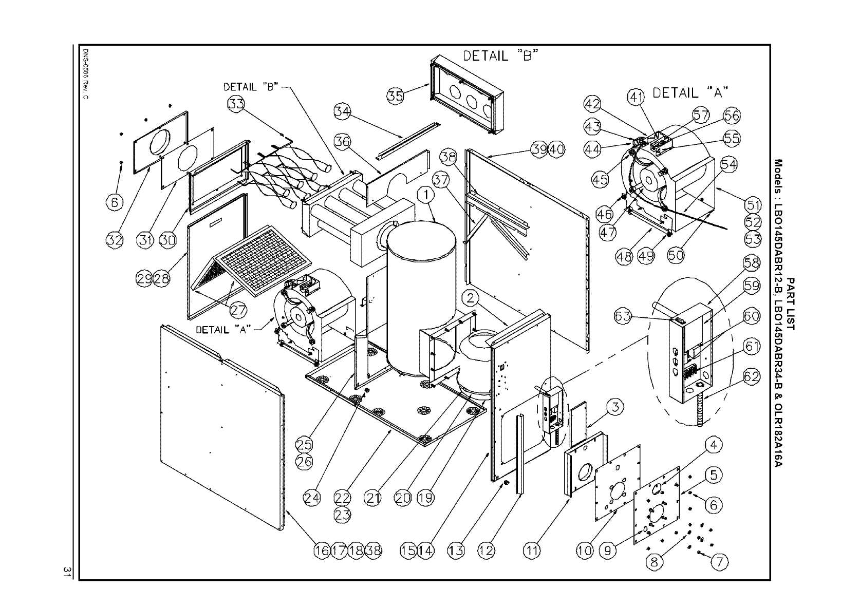
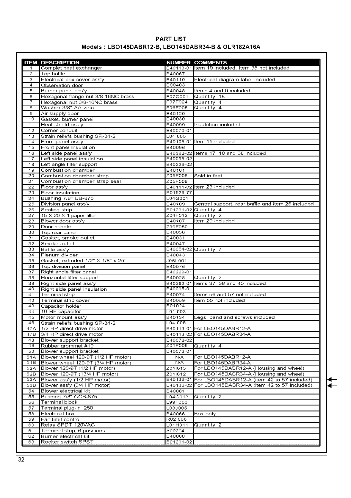
Models : LBO145DABR12-B, LBO145DABR34-B & OLR182A16A
Complet heat exchanger
2 Top baffle
3 Electrical box cover ass'y
4 Observation door
5 Burner panel ass'y
6 Hexagonal flange nut 3/8-16N0 brass
7 Hexagonal nut 3/8-16N0 brass
8 Washer 3/8" AA zinc
9 Air supply door
10 Gasket, burner panel
11 Heat shield ass'y
12 Corner conduit
13 Strain reliefs bushing 8R-34-2
14 Front panel ass'y
15 Front panel insulation
16 Left side panel ass'y
17 Left side panel insulation
18 Left angle filter support
19 Combustion chamber
20 Combustion chamber strap
21 Combustion chamber strap seal
22 Floor ass'y
23 Floor insulation
24 Bushing 7/8" UB-875
25 Division panel ass'y
26 Sealing strip
27 15 X 20 X 1 paper filter
28 Blower door ass'y
29 Door handle
30 Top rear panel
31 Gasket, smoke outlet
32 Smoke outlet
33 Baffle ass'y
34 Plenum divider
35 Gasket, extruded 1/2" X 1/8" x 25'
36 Top division panel
37 Right angle filter panel
38 Horizontal filter support
39 Right side panel ass'y
40 Right side panel insulation
41 Terminal strip
42 Terminal strip cover
43 Capacitor holder
44 10 MF capacitor
45 Motor mount ass'y
46 Strain reliefs bushing SR-34-2
47A 1/2 HP direct drive motor
47B 3/4 HP direct drive motor
48 Blower support bracket
49 Rubber ,qrommet #19
50 Blower support bracket
51A Blower wheel 120-9T (1/2 HP motor)
51 B Blower wheel 120-9T (3/4 HP motor)
52A Blower 120-9T (1/2 HP motor)
52B Blower 120-9T (13/4 HP motor)
53A Blower ass'y (1/2 HP motor)
53B Blower ass'y (3/4 HP motor)
54 Blower electrical kit
55 Bushing 7/8" OOB-875
56 Terminal block
57 Terminal plug-in .250
58 Electrical box
59 Fan limit control
60 Relay SPDT 120VAC
61 Terminal strip, 6 positions
62 Burner electrical kit
63 Rocker switch SPST
B40118-01 Item 19 included. Item 35 not included
B40067
B40110 Electrical diagram label included
BO04O3
B40048 Items 4 and 9 included
FO7OO01 _uantity: 18
FO7FO24 _uantity: 4
FO6FO05 :::)uantity: 4
B40120
B40030
B40099 Insulation included
B40O7O-Ol
L041005
B40105-01 Item 15 included
B40096
B40362-02 Items 17, 18 and 38 included
B40095-02
B40229-02
B40161
ZO5FO08 Sold in feet
ZO5FO09
B40111-02 Item 23 included
B01526-77
L04G0Ol
B40109 Dentral support, rear baffle and item 26 included
B01291-02 :)uantity: 4
ZO4FO12 :3uantity: 2
B40107 Item 29 included
Z99FO50
B40050
B40031
B40047
B40054-02 _uantity: 7
B40043
J06L001
B40076
B40229-01
B40028
B40362-01
B40095-01
B40074
B40059
B01024
L011003
B40134
L041005
B40113-01
B40113-02
B40072-02
ZO1FO06
B40072-01
N/A
N/A
Z011015
Z011012
B40136-01
B40136-02
B40081
L04G013
L99FOO3
LO3J0O5
B40066
R021006
LO1H011
A00294
B40080
B01291-02
:::)uantity: 2
Items 37, 38 and 40 included
Items 56 and 57 not included
Item 55 not included
_egs, band and screws included
--or LBO145DABR12-A
--or LBO145DABR34-A
:3uantity: 4
--or LBO145DABR12-A
--or LBO145DABR34-A
--or LBO145DABR12-A (Housing and wheel)
--or LBO145DABR34-A (Housing and wheel)
--or LBO145DABR12-A (item 42 to 57 included)
--or LBO145DABR34-A (item 42 to 57 included)
:::)uantity: 2
Box only
:::)uantity: 2
4--
32
U
z
o
/c
c)
DETAIL "A"
f \
#
£
11
PART LIST
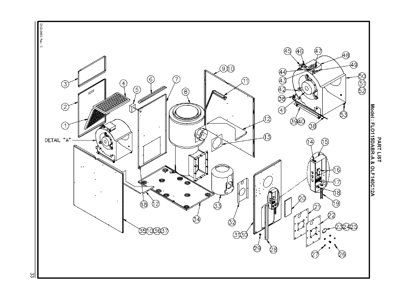
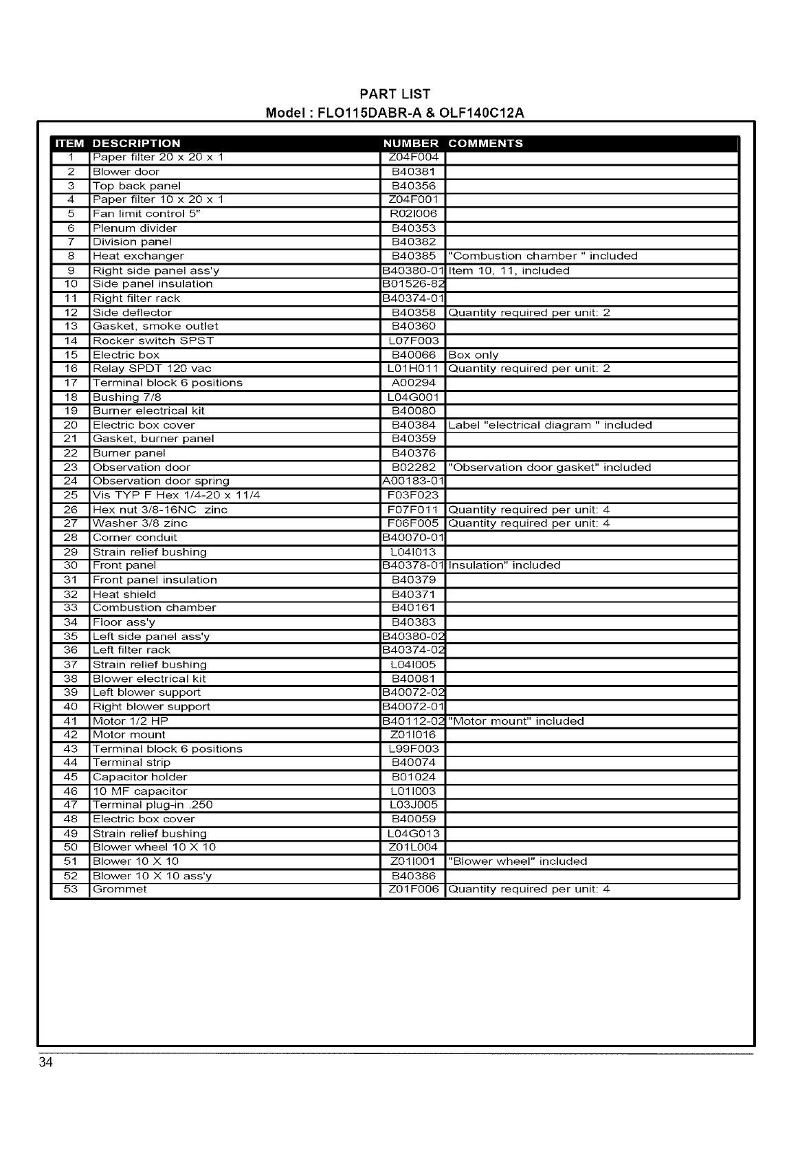
Model : FLO115DABR-A &OLF140C12A
Im]::1f.,I[_]_| I"..ilII[o] _ ,_LIII_vAi:] =1:i [_[o) _vAi_vAI=1_III[_
Paper filter 20 x 20 x 1 Z04F004
2 Slower door S40381
3 Top back panel S40356
4 Paper filter 10 x 20 x 1 Z04F001
5 Fan limit control 5" R021006
6 Plenum divider S40353
7 Division panel S40382
8 Heat exchanger B40385 "Combustion chamber " included
9 Right side panel ass'y B40380-01 Item 10, 11, included
10 Side panel insulation B01526-82
11 Right filter rack B40374-01
12 Side deflector B40358 Quantity required per unit: 2
13 Gasket, smoke outlet S40360
14 Rocker switch SPST L07F003
15 Electric box B40066 Box only
16 Relay SPDT 120 vac L01H011 Quantity required per unit: 2
17 Terminal block 6 positions A00294
18 Bushing 7/8 L04G001
19 Burner electrical kit S40080
20 Electric box cover B40384 Label "electrical diagram " included
21 Gasket, burner panel S40359
22 Burner panel $40376
23 Observation door S02282 "Observation door gasket" included
24 Observation door spring _,00183-01
25 Vis TYP F Hex 1/4-20 x 11/4 F03F023
26 Hex nut 3/8-16N0 zinc F07F011 Quantity required per unit: 4
27 Washer 3/8 zinc F06F005 Quantity required per unit: 4
28 Corner conduit B40070-01
29 Strain relief bushing L041013
30 Front panel B40378-01 Insulation" included
31 Front panel insulation S40379
32 Heat shield S40371
33 Combustion chamber S40161
34 Floor ass'y S40383
35 Left side panel ass'y B40380-02
36 Left filter rack B40374-02
37 Strain relief bushing L041005
38 Blower electrical kit S40081
39 Left blower support B40072-02
40 Right blower support B40072-01
41 Motor 1/2 HP B40112-02 "Motor mount" included
42 Motor mount Z011016
43 Terminal block 6 positions L99F003
44 Terminal strip S40074
45 Capacitor holder S01024
46 10 MF capacitor L011003
47 Terminal plug-in .250 L03J005
48 Electric box cover S40059
49 Strain relief bushing L04G013
50 Slower wheel 10X 10 Z01L004
51 Blower 10 X 10 Z011001 "Blower wheel" included
52 Blower 10 X 10 ass'y S40386
53 Grommet Z01F006 Quantity required per unit: 4
34
