ICP Package Units(both Units Combined) Manual L0522880
User Manual: ICP ICP Package Units(both units combined) Manual ICP Package Units(both units combined) Owner's Manual, ICP Package Units(both units combined) installation guides
Open the PDF directly: View PDF ![]() .
.
Page Count: 22
Installation
Instructions
Three Phase 3 to 5 Ton
Direct Drive Blower
Contents
Unit Dimensions ............ 2-3
1. Safety Labeling /Signal Words . 4
2. Safe Installation Requirements . 4
3. Locating the Unit .............. 5
4. Gas Supply and Piping ........ 8
5. Electrical Wiring .............. 11
6. Ductwork .................... 11
7. Economizer .................. 12
8. Start-up Procedures .......... 13
9. Operation .................... 14
10. Maintenance ................ 15
11. Rigging Instructions ........ 20
COMBINATIONUNITS
GASHEAT/ELECTRICCOOL
Printed in U,S.A. 509 01 1102 02 1/6/04
_Installation Instructions Combination Units I
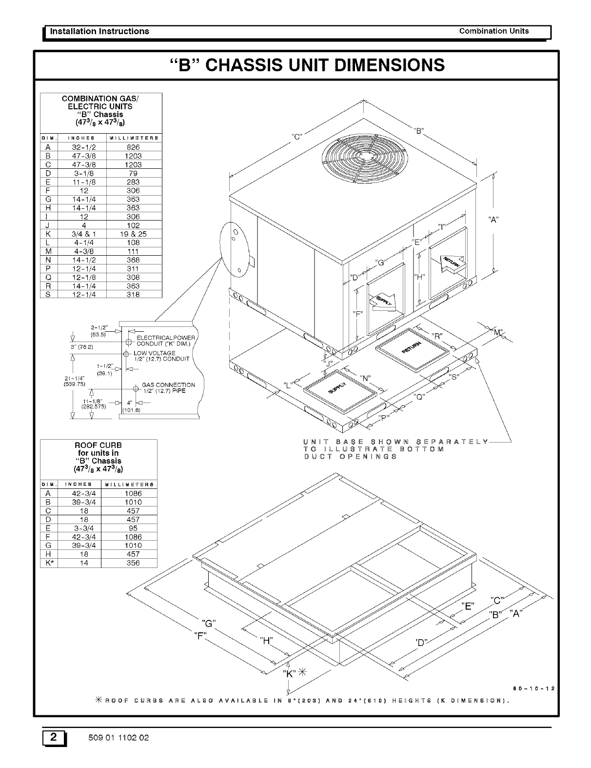
"B" CHASSIS UNIT DIMENSIONS
A
B
C
D
E
F
G
H
I
J
K
L
M
N
P
Q
R
S
A
B
C
D
E
F
G
H
K*
COMBINATION GAS/
ELECTRIC UNITS
"B" Chassis /A
(473/8 X 473/8)
,,o,Es M,UL,M_E,8 "C."--____"E"B"
82-i/2 828 / _ __'-._
47-3/8 I1203 _ _ _ _((_(_(_(_-._)_)_)_) ))))})// _. _.
47-3/8 I 1208 _ _ _._____________________/////_ _t
3-1/8 I 79 _ /__/ _. _
11-1/8 I 283 _ _ /_
12 I 306 _" _/
14-1/4 I 363 _ //
14-1/4I 363 _ _
12 I 306 "_ _ /t "A"
4 102 'T'/"
3/4&1 19&25 #_ _ _ _._'l"_j
4-1/4IlO8 (_ _ _ .i'E'_'_
12-1/8 308 / / _ 'D'_" _ "H" -"J / /
14-1/4 363 //_ // _0_
12_1 4I 318
2-i/2" :_ I
(635) ELECTRICAL POWER
:, _ co.o_,T_"_"o,_.) _ _<.</_J _ _..'-._>_ /"
_7o_ ,_ --.._--._.__ .__ ..>___
1-1/2" J
I _>_
(53975) _""_ "L''_ _ _ _.. /_ \
Ii L_ 1/2"<12#)PIPE /_ _ _ "_'_'_" /._,,_,/_ \
ROOF CURB PA RATg LY
forunitsin TO BLLU8YRAYE BOY=TOM
"B"Chassis # U CT 0 P E N BN G S
(473/8 x 473/8)
BNCHE8 MBLLBMETER8
42-3/4 1086
39-3/4 1010 // /_....
18 457 // _ _
18 457 //- /v
3-3/4 95 // / .././'_2..._
42-3/4 1086 _ / // _
3913/4 10;O _ _ __ "-._'_
/q_ROOF CURB8 gNg ALSO AVAILANLE IN 8"{2Q3) AND 24"{610) HN_GHT8 {K D_MNNS_@N}=
E_ 50901 110202
I Combination Units Installation Instructions
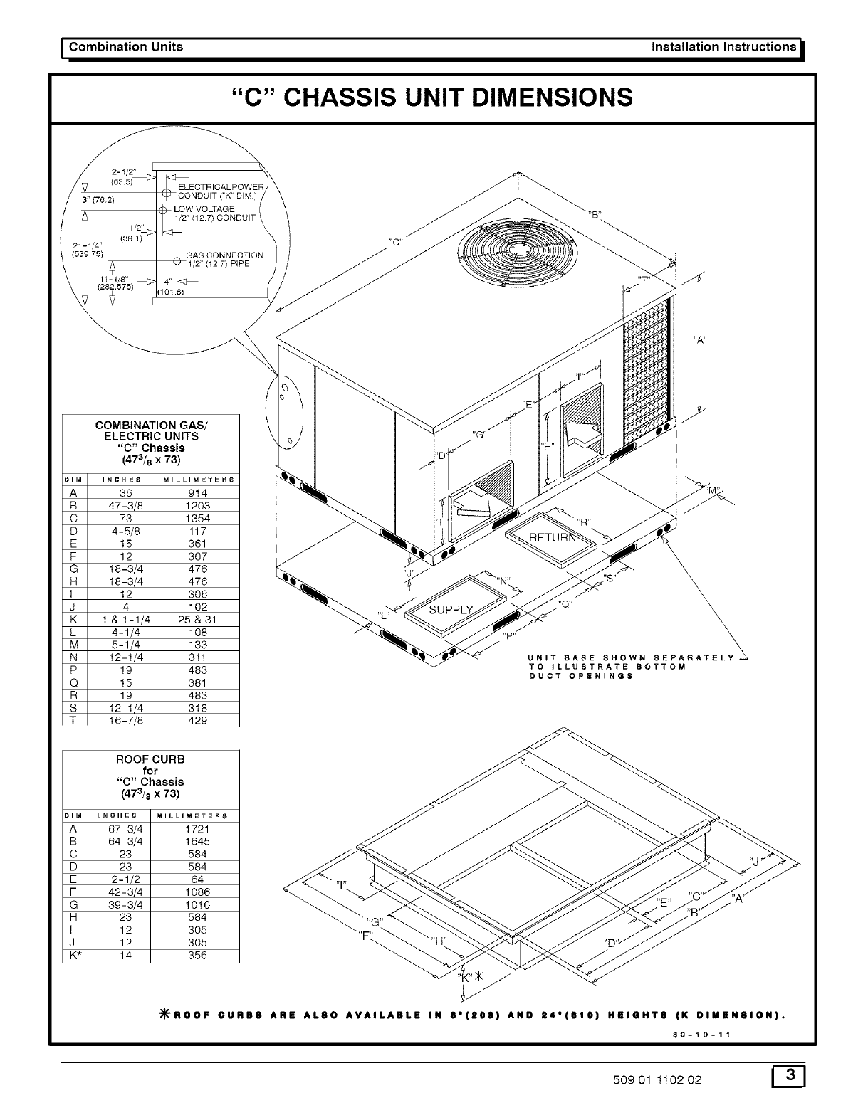
"C" CHASSIS UNIT DIMENSIONS
2-1/2"
3" (762) ("K" DIM.)
LOW VOLTAGE
1/2" (12.7) CONDUIT
1- 1/2"
21-1/4"
(539.75) GAS CONNECTION
11-1/8"
(101.6)
COMBINATION GAS/
ELECTRIC UNITS
"C" Chassis
(473/8 x 73)
_IM. INCHES M_LLIM_T_RS
A 36 914
B 47-3/8 1203
C 73 1354
D 4-5/8 117
E 15 361
F 12 307
G 18-3/4 476
H 18-3/4 476
]12 306
J 4 102
K 1 &1-1/4 25&31
L 4-1/4 108
M 5-1/4 133
N 12-1/4 311
P 19 483
Q 15 381
R 19 483
S 12-1/4 318
T 16-7/8 429
ROOF CURB
for
"C" Chassis
(473/8 x 73)
DIM. _NCHE8 MILLIMETER8
A 67-3/4 1721
B 64 - 3/4 1645
C 23 584
D 23 584
E 2-1/2 64
F 42-3/4 1086
G 39 - 3/4 1010
H 23 584
I 12 305
J 12 305
K* 14 356
"C"
"G"
,,p,,
"R"
UNIT BASE SHOWN SEPARAT
TO ILLUSTRATE BOTTOM
DUCT OPENINGS
"F\
_ROOF OURB8 ARE AL80 AVAILABLE IN 8"(208) AND Z4"(610) HEIGHT8 (K DIMENSION).
80-t0-11
50901 110202 E_]
I Installation Instructions Combination Units I
1. Safety Labeling and Signal Words
Danger, Warning and Caution
The signal words DANGER, WARNING and CAUTION are used
to identify levels of hazard seriousness. The signal word DAN-
GER is only used on product labels to signify an immediate haz-
ard. The signal words WARNING and CAUTION will be used on
product labels and throughout this manual and other manuals that
may apply to the product.
Signal Words
DANGER -immediate hazards which WILL result in severe per-
sonal injury or death.
WARNING - Hazards or unsafe practices which COULD result in
severe personal injury or death.
2. Safe Installation Requirements
CAUTION - Hazards or unsafe practices which COULD result in
minor personal injury or product or property damage.
Signal Words in Manuals
The signal word WARNING is used throughout this manual in the
following manner:
The signal word CAUTION is used throughout this manual in the
following manner:
CAUTION
Installation or repairs made by unqualified persons can
result in hazards to you and others. Installation MUST
conform with local building codes or, in the absence of
local codes, with the ANSI Z223.1-1990 National Fuel
Gas Code and the National Electrical Code
NFPA70-1990 or in Canada the National Standard CAN/
CGA B149.1 and CSA C.22.1 -Canadian Electrical
Code Part 1.
The information contained in this manual is intended
for use by a qualified service technician familiar with
safety procedures and equipped with the proper tools
and test instruments.
Failure to carefully read and follow all instructions in
this manual can result in furnace malfunction, property
damage, personal injury and/or death.
• Installation MUST conform to the most current version of
the following standards or a superseding standard.
In the USA:
•. ANSI Z223.1-1990 National Fue! Gas Code
• National Electrical Code NFPA70-1990
In Canada:
• National Standard CAN/CGA B149.1
• CSA C.22.1 - Canadian Electrical Code Part 1.
• Do NOT use this furnace as a construction heater.
• Use only the type of gas approved for this furnace (see rat-
ing plate).
• Do NOT use open flame to test for gas leak.
• Seal supply and return air ducts.
NOTE: It is the personal responsibility and obligation of the cus-
tomer to contact a qualified installer to ensure that the installation
is adequate and conforms to governing codes and ordinances.
CAUTION
It is recommended that a qualified service technician check
the heat exchanger integrity every two (2) years, after the first
four (4) years of operation.
Check Pre-existing Common Vent From Old
Furnace
If the installation of the combination unit involves removing an ex-
isting furnace from a common vent with other appliances, the
venting system will probably be too large for the remaining ap-
pliances and they will not vent properly. The venting system
MUST be checked according to the following procedure.
NOTE: The following steps shall be followed with each appliance
remaining connected tothe common venting system placed in op-
eration, while the other appliances remaining connected to the
common venting system are not in operation.
1. Seal any unused openings in the common venting system.
Visually inspect the venting system for proper size and hor-
izontal pitch to ensure there is no blockage or restriction,
leakage, corrosion or other deficiencies which could cause
an unsafe condition.
insofar as is practical, close all doors and windows and all
doors between the space in which the appliances remain-
ing connected to the common venting system are located
and other spaces of the building
Turn on clothes dryers and any appliance not connected to
the common venting system. Turn on any exhaust fans,
such as range hoods and bathroom exhausts, so they will
operate at maximum speed. Do NOT operate a summer
exhaust fan. Close fireplace dampers.
Follow the lighting instructions, Place the appliance being
inspected in operation. Adjust thermostat so appliance wil!
operate continuously.
Test for spillage at the draft hood relief opening after 5 min-
utes of main burner operation. Use the flame of a match or
E_I 50901 110202
I Combination Units
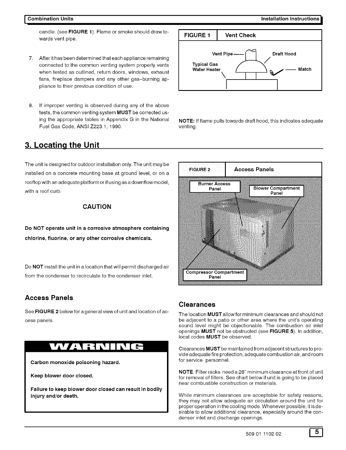
candle. (see FIGURE 1). Flame or smoke should drawto-
wards vent pipe.
After it has been determined that each appliance remaining
connected to the common venting system properly vents
when tested as outlined, return doors, windows, exhaust
fans, fireplace dampers and any other gas-burning ap-
pliance to their previous condition of use.
Installation Instructions
FIGURE 1 Vent Check
Vent Pipe--___ Draft Hood
Typical Gas _/
WaterHeaterx [I I _ v--Match
I j
If improper venting is observed during any of the above
tests, the common venting system MUST be corrected us-
ing the appropriate tables in Appendix G in the National
Fuel Gas Code, ANSI Z223.1, 1990.
NOTE: If flame pulls towards draft hood, this indicates adequate
venting.
3. Locating the Unit
The unit is designed for outdoor installation only. The unit may be
installed on a concrete mounting base at ground level, or on a
rooftop with an adequate platform or if using as a downflow model,
with a roof curb.
CAUTION
Do NOT operate unit in a corrosive atmosphere containing
chlorine, fluorine, or any other corrosive chemicals.
Do NOT install the unit in a location that will permit discharged air
from the condenser to recirculate to the condenser inlet.
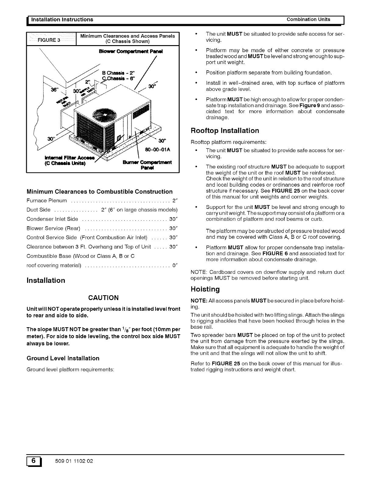
I FIGURE 2Access Panels
Access Panels
See FIGU RE 2 below for a general view of unit and location of ac-
cess panels.
Carbon monoxide poisoning hazard.
Keep blower door closed.
Failure to keep blower door closed can result in bodily
injury and/or death.
Clearances
The location MUST allow for minimum clearances and should not
be adjacent to a patio or other area where the unit's operating
sound level might be objectionable. The combustion air inlet
openings MUST not be obstructed (see FIGURE 5). In addition,
local codes MUST be observed.
Clearances MUST be maintained from adjacent structures to pro-
vide adequate fire protection, adequate combustion air, and room
for service personnel.
NOTE: Filter racks need a 26" minimum clearance at front of unit
for removal of filters. See chart below if unit is going to be placed
near combustible construction or materials.
While minimum clearances are acceptable for safety reasons,
they may not allow adequate air circulation around the unit for
proper operation in the cooling mode. Whenever possible, it is de-
sirable to allow additional clearance, especially around the con-
denser inlet and discharge openings.
50901 110202 E_]
I Installation Instructions Combination Units I
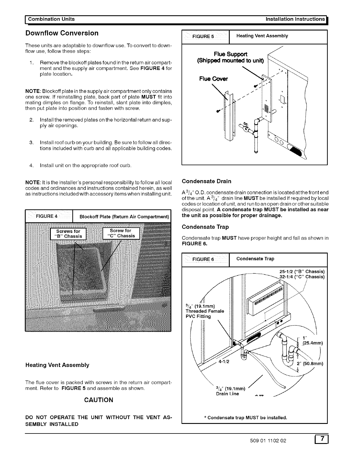
Minimum Clearances and Access Panels
FIGURE 3 (C Chassis Shown)
sk>_r _Pmww
Bcm.+,m,:
/+++++za_'
30"
80-00-01A
Minimum Clearances to Combustible Construction
Furnace Plenum .................................... 2"
Duct Side ................ 2" (6" on large chassis models)
Condenser Inlet Side ............................... 30"
Blower Service (Rear) .............................. 30"
Control Service Side (Front Combustion Air Inlet) ...... 30"
Clearance between 3 Ft. Overhang and Top of Unit ..... 30"
Combustible Base (Wood or Class A, B or C
roof covering material) ............................... 0"
Installation
CAUTION
Unit will NOT operate properly unless it is installed level front
to rear and side to side.
The slope MUST NOT be greater than 1/8" per foot (10mm per
meter). For side to side leveling, the control box side MUST
always be lower.
Ground Level Installation
Ground level platform requirements:
The unit MUST be situated to provide safe access for ser-
vicing.
Platform may be made of either concrete or pressure
treated wood and MUST be level and strong enough to sup-
port unit weight.
Position platform separate from building foundation.
Install in well-drained area, with top surface of platform
above grade level.
Platform MUST be high enough to allow for proper conden-
sate trap installation and drainage. See Figure 9 and asso-
ciated text for more information about condensate
drainage.
Rooftop Installation
Rooftop platform requirements:
• The unit MUST be situated to provide safe access for ser-
vicing.
The existing roof structure MUST be adequate to support
the weight of the unit or the roof MUST be reinforced.
Check the weight of the unit in relation to the roof structure
and local building codes or ordinances and reinforce roof
structure if necessary. See FIGURE 25 on the back cover
of this manual for unit weights and corner weights.
• Support for the unit MUST be level and strong enough to
carry unit weight. The support may consist of a platform or a
combination of platform and roof beams or curb.
The platform may be constructed of pressure treated wood
and may be covered with Class A, B or C roof covering.
• Platform MUST allow for proper condensate trap installa-
tion and drainage. See FIGURE 6 and associated text for
more information about condensate drainage.
NOTE: Cardboard covers on downflow supply and return duct
openings MUST be removed before starting unit.
Hoisting
NOTE: All access panels MUST be secured in place before hoist-
ing.
The unit should be hoisted with two lifting slings. Attach the slings
to rigging shackles that have been hooked through holes in the
base rail.
Two spreader bars MUST be placed on top of the unit to protect
the unit from damage from the pressure exerted by the slings.
Make sure that all equipment is adequate to handle the weight of
the unit and that the slings will not allow the unit to shift.
Refer to FIGURE 25 on the back cover of this manual for illus-
trated rigging instructions and weight chart.
E_ 50901 110202
I Combination Units Installation Instructions
Downflow Conversion
These units are adaptable to downflow use. To convert to down-
flow use, follow these steps:
1. Remove the blockoff plates found in the return air compart-
ment and the supply air compartment. See FIGURE 4 for
plate location.
NOTE: Blockoff plate in the supply air compartment only contains
one screw. If reinstalling plate, back part of plate MUST fit into
mating dimples on flange. To reinstall, slant plate into dimples,
then put plate into position and fasten with screw.
2. Install the removed plates on the horizontal return and sup-
ply air openings.
3. Install roof curb on your building. Be sure to follow all direc-
tions included with curb and all applicable building codes.
FIGURE 5 JHeating Vent Assembly
Flue Support
(Shipped moume(:lto unit)
Flue Cover
/
4. Install unit on the appropriate roof curb.
NOTE: It is the installer's personal responsibility to follow all local
codes and ordinances and instructions contained herein, as well
as instructions included with accessory items when installing unit.
Blockoff Plate (Return Air Compartment)
Heating Vent Assembly
The flue cover is packed with screws in the return air compart-
ment. Refer to FIGURE 5and assemble as shown.
CAUTION
DO NOT OPERATE THE UNIT WITHOUT THE VENT AS-
SEMBLY INSTALLED
Condensate Drain
A3/4" O.D. condensate drain connection is located at the front end
of the unit. A 3/4" drain line MUST be installed if required by local
codes or location of unit, and run to an open drain or other suitable
disposal point. A condensate trap MUST be installed as near
the unit as possible for proper drainage.
Condensate Trap
Condensate trap MUST have proper height and fall as shown in
FIGURE 6,
FIGURE 6]Condensate Trap
25-1/2 ("B" Chassis)
("C" Chassis)
3/4" (19.1mm)
Threaded Female
PVC Fitting
4-1/2
_(25.4mm)
)
2" (50.8mm)
\3/4" (19.1mm) '
Drain Line
*Condensate trap MUST be installed.
50901 110202 [_]

IInstallation Instructions
4. Gas Supply and Piping
Combination Units I
Because there are many types of liquefied petroleum (LP) gases,
the term LP as used in this manual refers to propane gas. If you
intend to use any type of LP gas, proper precautions MUST be
used in the handling, piping, and use ofsuch gas. NOTE: In Cana-
da, LP installations MUST be performed by licensed LP installers.
The Rating Plate located on the side panel on the unit contains the
model number, type of gas and gas input rating, and other impor-
tant information.
Fire and/or explosion hazard.
Make certain the unit is equipped to operate on the type
of gas available. Models designated as natural gas are
to be used with natural gas only. Models designated for
use with liquefied petroleum (LP) gas are shipped with
orifices sized for commercially pure propane gas. They
MUST not be used with butane or a mixture of butane
and propane unless properly sized orifices are installed
by a licensed LP installer.
Failure to follow this warning can result in property
damage, personal injury, and/or death.
Gas Pressures
1. Do NOT allow minimum gas supply pressure to fall below
the minimums. Doing so will decrease input to furnace. Re-
fer to FIGURE 7 for gas supply pressures.
2. Gas input MUST NOT exceed rated input shown on rating
plate.
3. Do NOT allow pressures to exceed the maximum limits as
listed in FIGURE 7.
NOTE: If gas supply pressures are not correct, contact your gas
supplier.
Gas Pressures
Natural Gas LP Gas
Minimum
Inlet 4.5"W.C. (1120 Pa) 11" W.C. (2740 Pa)
Pressure
Recom.
Inlet 7" W.C. (1740 Pa) 11" W.C. (2740 Pa)
Pressure
Maximum
Inlet 13"W.0. (3230 Pa) 13"W.C. (3230 Pa)
Pressure
Manifold 3.5" W.C. (870 Pa) 10" W.C. (2490 Pa)
Pressure
Manifold Pressures
Manifold pressures are covered in the startup procedure section.
Refer to Chapter 8, Start-Up Procedures on Page 13.
Gas Piping
The gas supply line MUST be of adequate size to handle the Btu/
hr requirements and length of the run for the unit being installed.
Determine the minimum pipe size for natural gas from the table in
Figure 8 &Figure 9. Base the length of the run from the gas meter
or source to the unit.
Gas Pipe Size
Btu ratings of all other gas appliances MUST be considered for
sizing of main gas line. Check gas line to installation for com-
pliance with local codes or, in the absence of local codes, with the
National Fuel Gas Code ANSI Z223.1-1990 and in Canada the
National Standard CAN/CGA B149.1 current editions.
FIGURE 8 GasPipe Size, LengthandBtu/hr Capacityfor Sched-
ule40 Iron Pipe (English)
NATURAL GAS
PipeLength Btu/hr (in thousands)
(Includes
Fittings) 3/4" 1" 11/4" 11/2" 2"
20' 190 350 730 1,100 2,100
40' 130 245 500 760 1,450
60' 105 195 400 610 1,150
LP GAS
PipeLength Btu/hr(inthousands)
(Includes
Fittings) 1/2" 3/4" 1" 11/4" 11/2"
20' 189 393 732 1,496 2,299
40' 129 267 504 1,039 1,559
60' 103 217 409 834 1,275
FIGURE 9GasPipe Size, LengthandBtu/hr Capacityfor Sched-
ule40 Iron Pipe(English)
NATURAL GAS
PipeLength kW**
(Includes
Fittings) 3/4" 1" 11/4" 11/2" 2"
6.1m 56 103 214 322 615
12.2m 38 72 147 223 425
18.3m 31 57 117 179 337
LP GAS
PipeLength kW**
(includes
Fittings) 1/2" 3/4" 1" 11/4" 11/2"
6.1m 55 115 215 438 574
12.2m 38 78 148 305 457
18.3m 30 64 120 244 374
**kW (Kilowatts) is the metric equivalent of Btu/hr.
FIGURE 10 Orifice Sizes
Gas Type Specific Gravity Btu/ft 3(k J/L) Pilot Orifice Sizes
Natural 0.6 1000 .018#
Propane 1.53 2500 .012#
#Adjust pilot flame as needed
E_I 50901 110202
I Combination Unite
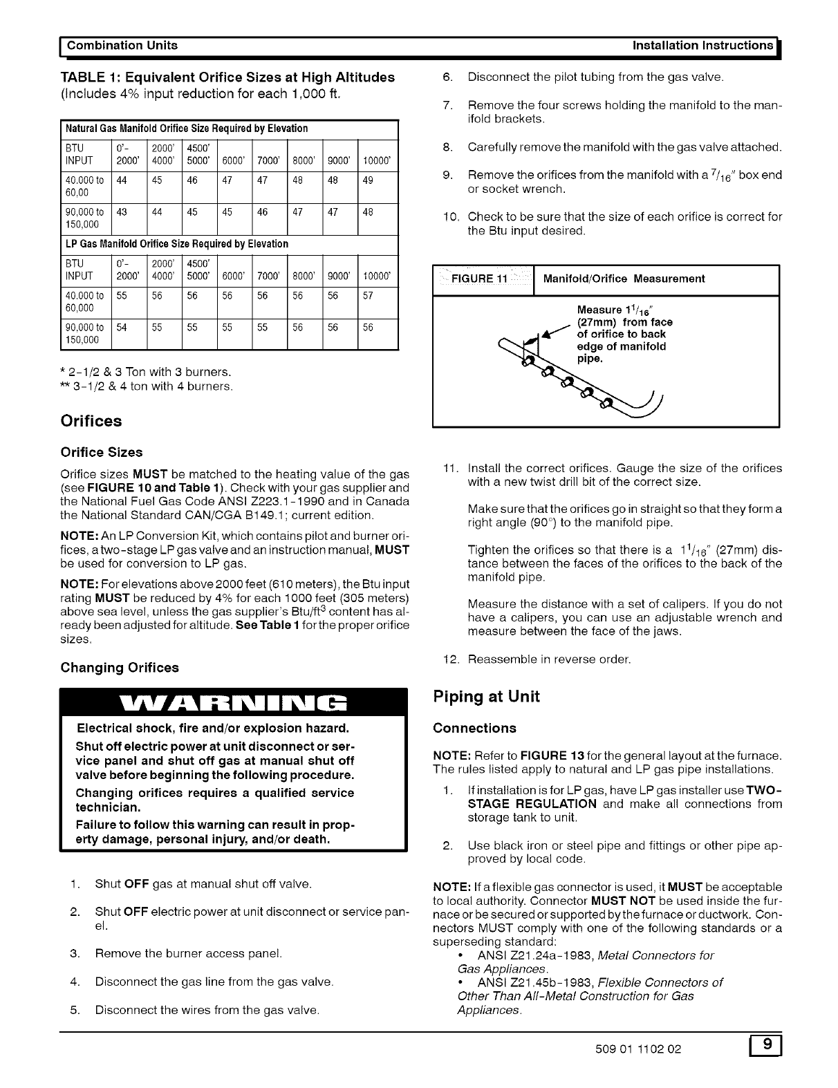
TABLE 1: Equivalent Orifice Sizes at High Altitudes
(Includes 4% input reduction for each 1,000 ft.
Natural GasManifoldOrifice Size RequiredbyElevation
BTU 0'- 2000' 4500'
INPUT 2000' 4000' 5000' 6000' 7000' 8000' 9000' 10000'
40.000to 44 45 46 47 47 48 48 49
60,00
90,000to 43 44 45 45 46 47 47 48
150,000
LPGas ManifoldOrifice Size Required by Elevation
BTU 0'- 2000' 4500'
INPUT 2000' 4000' 5000' 6000' 7000' 8000' 9000' 10000'
40.000to 55 56 56 56 56 56 56 57
60,000
90,000to 54 55 55 55 55 56 56 56
150,000
*2-1/2 & 3 Ton with 3 burners.
** 3-1/2 & 4 ton with 4 burners.
Orifices
Installation Instructions
6. Disconnect the pilot tubing from the gas valve.
7. Remove the four screws holding the manifold to the man-
ifold brackets.
8. Carefully remove the manifold with the gas valve attached.
9. Remove the orifices from the manifold with a 7/16" box end
or socket wrench.
10. Check to be sure that the size of each orifice is correct for
the Btu input desired.
FIGURE ii I Manifold/Orifice Measurement
Measure 11/16"
(27mm) from face
__ .11Ak _of orifice to back
_,,,,",_J edg Iof manifold
Orifice Sizes
Orifice sizes MUST be matched to the heating value of the gas
(see FIGURE 10 and Table 1). Check with your gas supplier and
the National Fuel Gas Code ANSI Z223.1 -1 990 and in Canada
the National Standard CAN/CGA B149.1; current edition.
NOTE: An LP Conversion Kit, which contains pilot and burner ori-
fices, a two-stage LP gas valve and an instruction manual, MUST
be used for conversion to LP gas.
NOTE: For elevations above 2000 feet (610 meters), the Btu input
rating MUST be reduced by 4% for each 1000 feet (305 meters)
, 3
above sea level, unless the gas supplier s Btu/ft content has al-
ready been adjusted for altitude. See Table I for the proper orifice
sizes.
Changing Orifices
Electrical shock, fire and/or explosion hazard.
Shut off electric power at unit disconnect or ser-
vice panel and shut off gas at manual shut off
valve before beginning the following procedure.
Changing orifices requires a qualified service
technician.
Failure to follow this warning can result in prop-
erty damage, personal injury, and/or death.
1. Shut OFF gas at manual shut off valve.
2. Shut OFF electric power at unit disconnect or service pan-
el.
3. Remove the burner access pane!.
4. Disconnect the gas line from the gas valve.
5. Disconnect the wires from the gas valve.
11. install the correct orifices. Gauge the size of the orifices
with a new twist drill bit of the correct size.
Make sure that the orifices go in straight so that they form a
right angle (90 °) to the manifold pipe.
Tighten the orifices so that there is a 11/16" (27mm) dis-
tance between the faces of the orifices to the back of the
manifold pipe.
Measure the distance with a set of calipers, if you do not
have a calipers, you can use an adjustable wrench and
measure between the face of the jaws.
12. Reassemble in reverse order.
Piping at Unit
Connections
NOTE: Refer to FIGU RE 13 for the general layout at the furnace.
The rules listed apply to natural and LP gas pipe installations.
1. If installation is for LP gas, have LP gas installer use TWO-
STAGE REGULATION and make all connections from
storage tank to unit.
2. Use black iron or steel pipe and fittings or other pipe ap-
proved by local code.
NOTE: If a flexible gas connector is used, it MUST be acceptable
to local authority. Connector MUST NOT be used inside the fur-
nace or be secured or supported bythe furnace or ductwork. Con-
nectors MUST comply with one of the following standards or a
superseding standard:
• ANSI Z21.24a-1983, Metal Connectors for
Gas Appliances.
• ANSI Z21.45b-1983, Flexible Connectors of
Other Than All-Metal Construction for Gas
Appliances.
50901 110202 E_]
IInstallation Instructions Combination Units I
Fire and/or explosion hazard.
Gas connector MUST be properly installed and can NOT be
used inside the furnace.
Failure to do so can result in property damage, bodily inju-
ry or death.
Leak Check
1. Gas pressure MUST NOT exceed 1/2 PSIG (3450 Pa).
Checking gas piping above 1/2 PSIG (3450 Pa) requires
the gas valve and manual shutoff valve to be disconnected
during testing.
2. When checking gas piping to furnace, shut OFF manual
shutoff valve to furnace.
3. Test all pipes for leaks.
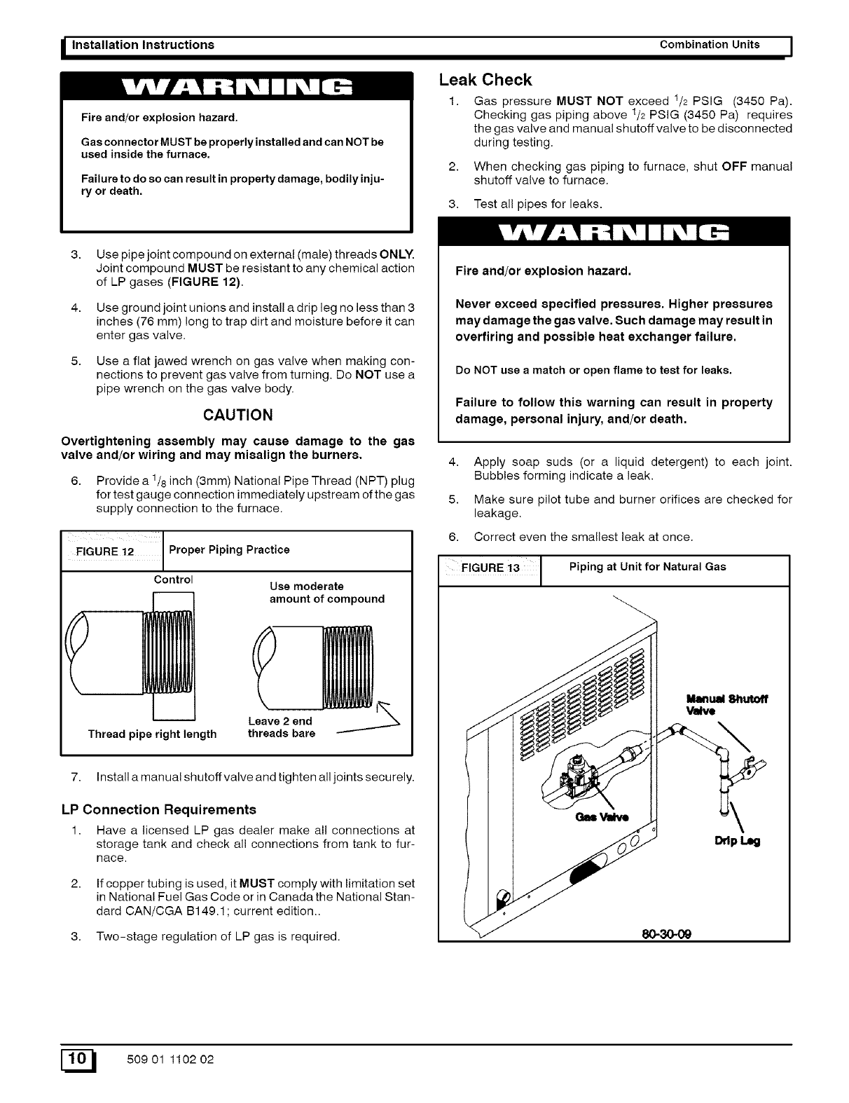
3. Use pipe joint compound on external (male) threads ONLY.
Joint compound MUST be resistant to any chemical action
of LP gases (FIGURE 12).
4. Use ground joint unions and install a drip leg no less than 3
inches (76 mm) long to trap dirt and moisture before it can
enter gas valve.
5. Use a flat jawed wrench on gas valve when making con-
nections to prevent gas valve from turning. Do NOT use a
pipe wrench on the gas valve body.
CAUTION
Overtightening assembly may cause damage to the gas
valve and/or wiring and may misalign the burners.
6. Provide a 1/8 inch (3mm) National Pipe Thread (NPT) plug
for test gauge connection immediately upstream of the gas
supply connection to the furnace.
FIGURE i2 J Proper Piping Practice
Control Use moderate
amount of compound
Thread pipe right length
Leave 2 end
threads bare
7. Install a manual shutoffvalve and tighten all joints securely.
LP Connection Requirements
1. Have a licensed LP gas dealer make all connections at
storage tank and check all connections from tank to fur-
nace.
If copper tubing is used, it MUST comply with limitation set
in National Fuel Gas Code or in Canada the National Stan-
dard CAN/CGA B149.1; current edition..
3. Two-stage regulation of LP gas is required.
Fire and/or explosion hazard.
Never exceed specified pressures. Higher pressures
may damage the gas valve. Such damage may result in
overfiring and possible heat exchanger failure.
Do NOT use a match or open flame to test for leaks.
Failure to follow this warning can result in property
damage, personal injury, and/or death.
4.
5.
6.
Apply soap suds (or a liquid detergent) to each joint.
Bubbles forming indicate a leak.
Make sure pilot tube and burner orifices are checked for
leakage.
Correct even the smallest leak at once.
FIGURE !3 1 Piping at Unit for Natural Gas
E_ 50901 110202
I Combination Units Installation Instructions
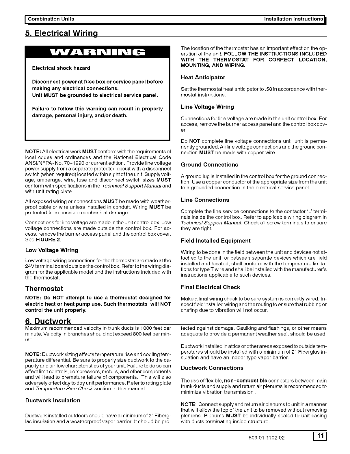
5. Electrical Wiring
Electrical shock hazard.
Disconnect power at fuse box or service panel before
making any electrical connections.
Unit MUST be grounded to electrical service panel.
Failure to follow this warning can result in property
damage, personal injury, and/or death.
The location of the thermostat has an important effect on the op-
eration of the unit. FOLLOW THE INSTRUCTIONS INCLUDED
WITH THE THERMOSTAT FOR CORRECT LOCATION,
MOUNTING, AND WIRING.
Heat Anticipator
Set the thermostat heat anticipator to. 58 in accordance with ther-
mostat instructions.
Line Voltage Wiring
Connections for line voltage are made in the unit control box. For
access, remove the burner access panel and the control box cov-
er.
NOTE: All electrical work MUST conform with the requirements of
local codes and ordinances and the National Electrical Code
ANSI/NFPA-No. 70-1990 or current edition. Provide line voltage
power supply from a separate protected circuit with a disconnect
switch (when required) located within sight of the unit. Supplyvolt-
age, amperage, wire, fuse and disconnect switch sizes MUST
conform with specifications in the Technical Support Manual and
with unit rating plate.
All exposed wiring or connections MUST be made with weather-
proof cable or wire unless installed in conduit. Wiring MUST be
protected from possible mechanical damage.
Connections for line voltage are made in the unit control box. Low
voltage connections are made outside the control box. For ac-
cess, remove the burner access panel and the control box cover.
See FIGURE 2.
Low Voltage Wiring
Low voltage wiring connections for the thermostat are made at the
24Vterminal board outside the control box. Refer to the wiring dia-
gram for the applicable model and the instructions included with
the thermostat.
Do NOT complete line voltage connections until unit is perma-
nently grounded. All line voltage connections and the ground con-
nection MUST be made with copper wire.
Ground Connections
A ground lug is installed in the control box for the ground connec-
tion. Use a copper conductor of the appropriate size from the unit
to a grounded connection in the electrical service panel.
Line Connections
Complete the line service connections to the contactor 'L' termi-
nals inside the control box. Refer to applicable wiring diagram in
Technical Support Manual. Check all screw terminals to ensure
they are tight.
Field Installed Equipment
Wiring to be done in the field between the unit and devices not at-
tached to the unit, or between separate devices which are field
installed and located, shall conform with the temperature limita-
tions for type T wire and shall be installed with the manufacturer's
instructions applicable to such devices.
Thermostat
NOTE: Do NOT attempt to use a thermostat designed for
electric heat or heat pump use. Such thermostats will NOT
control the unit properly,
Final Electrical Check
Make a final wiring check to be sure system is correctly wired. In-
spect field installed wiring and the routing to ensure that rubbing or
chafing due to vibration will not occur.
6. Ductwork
Maximum recommended velocity in trunk ducts is 1000 feet per
minute. Velocity in branches should not exceed 800 feet per min-
ute.
NOTE: Ductwork sizing affects temperature rise and cooling tem-
perature differential. Be sure to properly size ductwork to the ca-
pacity and airflow characteristics of your unit. Failure to do so can
affect limit controls, compressors, motors, and other components
and will lead to premature failure of components. This will also
adversely affect day to day unit performance. Refer to rating plate
and Temperature Rise Check section in this manual.
Ductwork Insulation
Ductwork installed outdoors should have a minimum of 2" Fiberg-
las insulation and a weatherproof vapor barrier. It should be pro-
tected against damage. Caulking and flashings, or other means
adequate to provide a permanent weather seal, should be used.
Ductwork installed in attics or other areas exposed to outside tem-
peratures should be installed with a minimum of 2" Fiberglas in-
sulation and have an indoor type vapor barrier.
Ductwork Connections
The use of flexible, non-combustible connectors between main
trunk ducts and supply and return air plenums is recommended to
minimize vibration transmission.
NOTE: Connect supply and return air plenums to unit in a manner
that will allow the top of the unit to be removed without removing
plenums. Plenums MUST be individually sealed to unit casing
with ducts terminating inside structure.
50901 110202
_Installation Instructions Combination Units I
Filters
All return air, including economizer air and outside damper air,
MUST pass through a filter before entering the evaporator. An
electronic air cleaner or other accessible filter arrangement
MUST be installed in the return air ductwork. This can ONLY be
done when the internal filters are removed and NO outdoor air ac-
cessories are used. Mimimum recommended filter areas are
based on a velocity of 300 ft/min for disposable filters and 500 ft/
min for high velocity filters (washable).
CAUTION
DO NOT OPERATE THE UNIT WITHOUT A FILTER.
7. Economizer
The purpose of an economizer is to:
• Provide cool outside air to the conditioned space during the
cooling cycle to minimize the use of the compressors.
• Bring outside air into the conditioned space to meet mini-
mum fresh air requirements whenever the circulation blow-
er is running.
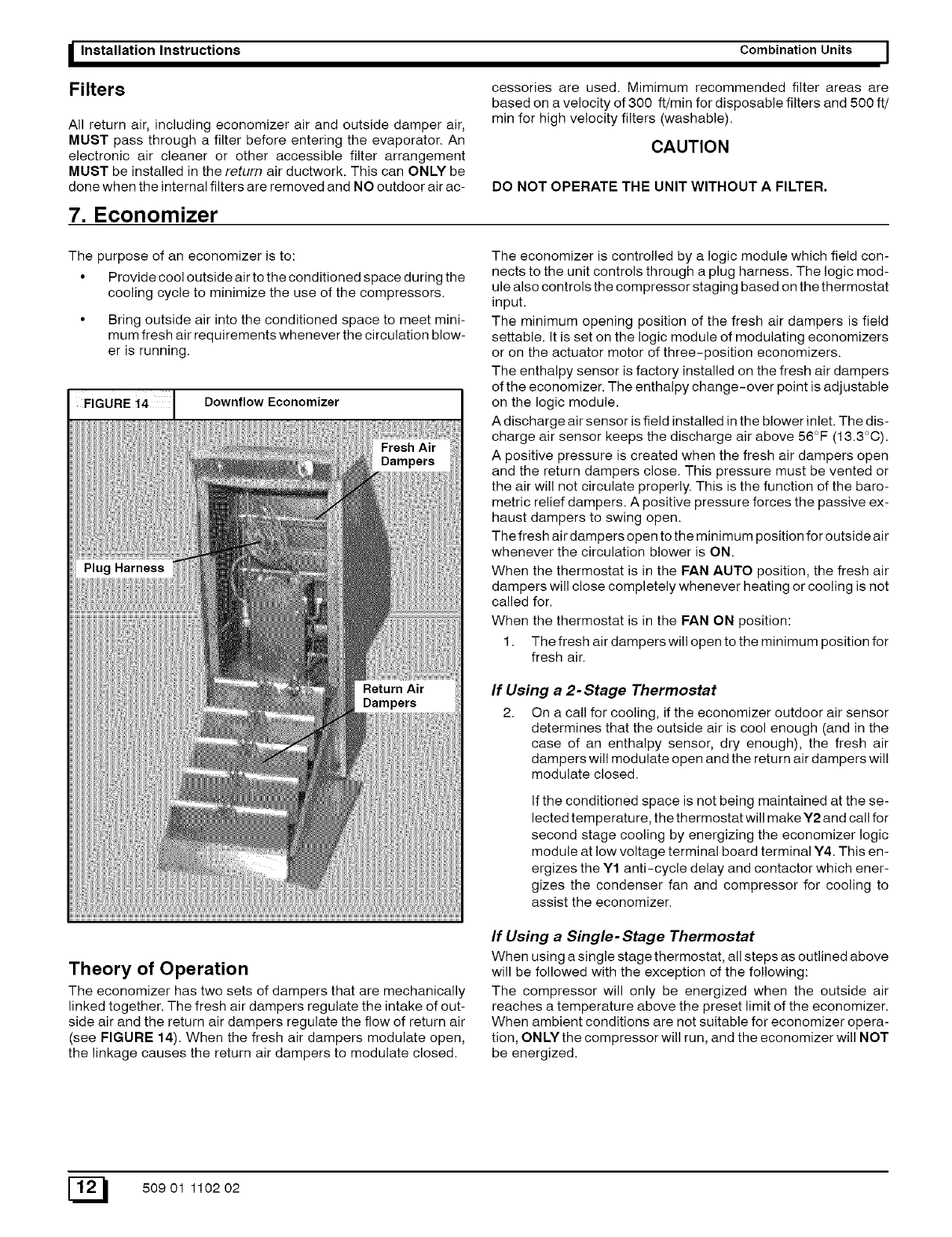
Downflow Economizer I
The economizer is controlled by a logic module which field con-
nects to the unit controls through a plug harness. The logic mod-
ule also controls the compressor staging based on the thermostat
input.
The minimum opening position of the fresh air dampers is field
settable. It is set on the logic module of modulating economizers
or on the actuator motor of three-position economizers.
The enthalpy sensor is factory installed on the fresh air dampers
of the economizer. The enthalpy change-over point is adjustable
on the logic module.
A discharge air sensor is field installed in the blower inlet. The dis-
charge air sensor keeps the discharge air above 56°F (13.3°C).
A positive pressure is created when the fresh air dampers open
and the return dampers close. This pressure must be vented or
the air will not circulate properly. This is the function of the baro-
metric relief dampers. A positive pressure forces the passive ex-
haust dampers to swing open.
The fresh air dampers open to the minimum position for outside air
whenever the circulation blower is ON.
When the thermostat is in the FAN AUTO position, the fresh air
dampers will close completely whenever heating or cooling is not
called for.
When the thermostat is in the FAN ON position:
1. The fresh air dampers will open to the minimum position for
fresh air.
If Using a 2-Stage Thermostat
2. On a call for cooling, if the economizer outdoor air sensor
determines that the outside air is cool enough (and in the
case of an enthalpy sensor, dry enough), the fresh air
dampers will modulate open and the return air dampers wil!
modulate closed.
If the conditioned space is not being maintained at the se-
lected temperature, the thermostat will make Y2 and call for
second stage cooling by energizing the economizer logic
module at low voltage terminal board terminal Y4. This en-
ergizes the Y1 anti-cycle delay and contactor which ener-
gizes the condenser fan and compressor for cooling to
assist the economizer.
Theory of Operation
The economizer has two sets of dampers that are mechanically
linked together. The fresh air dampers regulate the intake of out-
side air and the return air dampers regulate the flow of return air
(see FIGURE 14). When the fresh air dampers modulate open,
the linkage causes the return air dampers to modulate closed.
If Using a Single- Stage Thermostat
When using a single stage thermostat, all steps as outlined above
will be followed with the exception of the following:
The compressor will only be energized when the outside air
reaches a temperature above the preset limit of the economizer.
When ambient conditions are not suitable for economizer opera-
tion, ONLY the compressor will run, and the economizer will NOT
be energized.
E_ 50901 110202
I Combination Units Installation Instructions
8. Start-up Procedures
Fire and/or explosion hazard.
Do NOT attempt to light the pilot or burner with a match
or flame of any kind.
Failure to follow this warning can result in property
damage, personal injury, and/or death.
Check Before Starting
Check that the blower motor speed terminal block isset for
the correct heating and cooling speeds. Refer to the unit
wiring diagram and tech sheet label and/or Technicallnfor-
mation Manual.
2. Check to see that clean, properly sized air filters are
installed.
3. Replace all service access panels.
Reverse Rotation (Scroll
Compressors Only)
Three phase scroll compressor equipped units CAN run in re-
verse if improperly wired. If the compressor makes an unusually
loud noise, or if high and low side pressures are nearly identical,
this indicates reverse rotation. To correct, reverse any two wires
at line voltage connections ONLY. Do NOT rewire any circuits in-
side the unit to attempt correction of reverse rotation.
Manifold Gas Pressure Adjustment
NOTE: Make adjustment to manifold pressure with burners oper-
ating.
Fire or explosion hazard.
Turn OFF gas at shut off before connecting U-tube ma-
nometer.
Do NOT adjust manifold pressure more than -+0.3 inches
water column to obtain rated input.
Failure to properly set input pressure can result in proper-
ty damage, personal injury and/or death.
1. With gas OFF, Connect U-Tube manometer to tapped
opening on gas valve. Use manometer with a 0 to 12 inches
water column range.
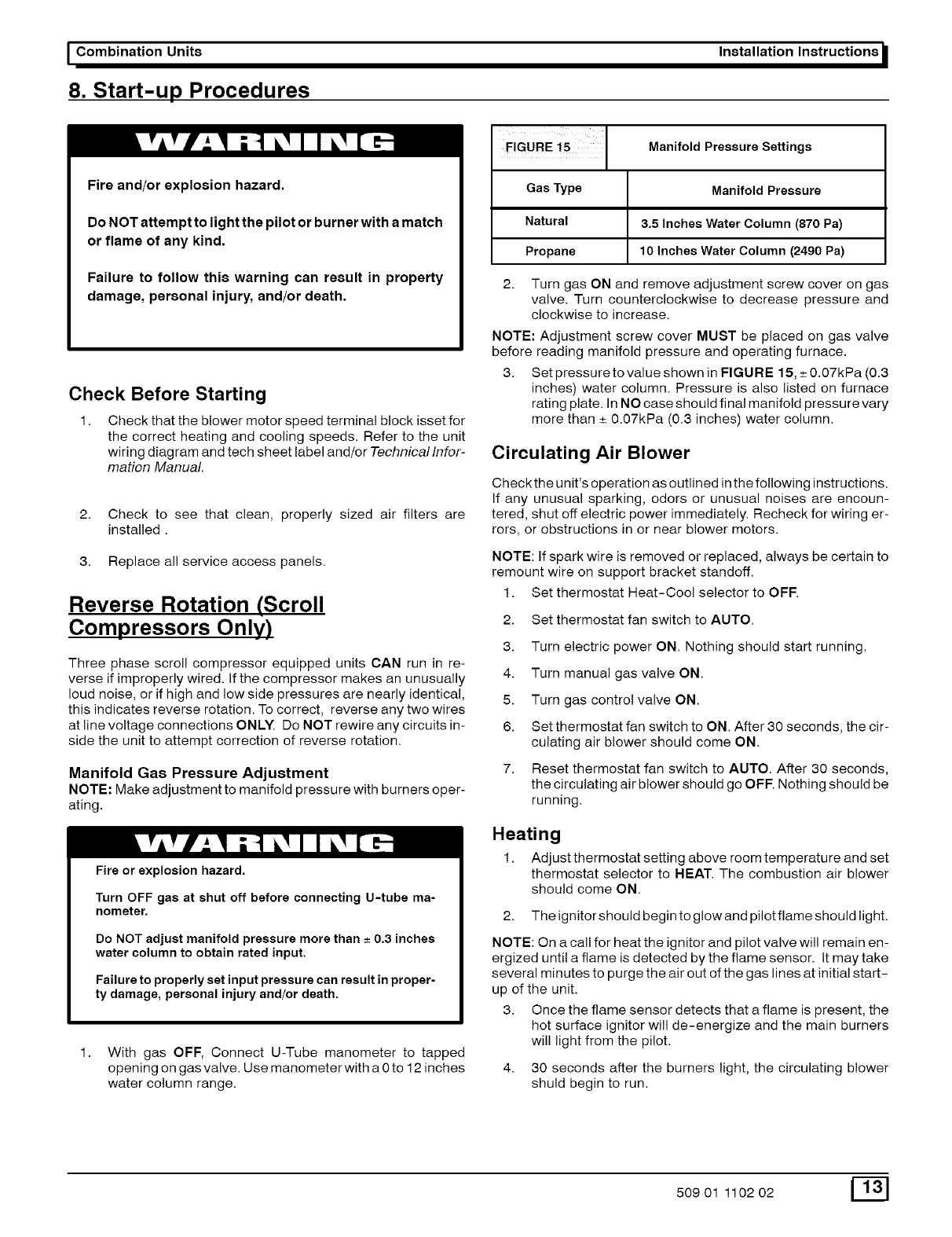
FIGURE 15 Manifold Pressure Settings
Gas Type Manifold Pressure
Natural 3.5 Inches Water Column (870 Pa)
Propane 10 Inches Water Column (2490 Pa)
2. Turn gas ON and remove adjustment screw cover on gas
valve. Turn counterclockwise to decrease pressure and
clockwise to increase.
NOTE: Adjustment screw cover MUST be placed on gas valve
before reading manifold pressure and operating furnace.
3. Set pressure to value shown in FIGURE 15, _+0.07kPa (0.3
inches) water column. Pressure is also listed on furnace
rating plate. In NO case should final manifold pressure vary
more than _+0.07kPa (0.3 inches) water column.
Circulating Air Blower
Check the unit's operation as outlined inthe following instructions.
If any unusual sparking, odors or unusual noises are encoun-
tered, shut off electric power immediately. Recheck for wiring er-
rors, or obstructions in or near blower motors.
NOTE: If spark wire is removed or replaced, always be certain to
remount wire on support bracket standoff.
1. Set thermostat Heat-Cool selector to OFF.
2. Set thermostat fan switch to AUTO.
3. Turn electric power ON. Nothing should start running.
4. Turn manual gas valve ON.
5. Turn gas control valve ON.
6. Set thermostat fan switch to ON. After 30 seconds, the cir-
culating air blower should come ON.
7. Reset thermostat fan switch to AUTO. After 30 seconds,
the circulating air blower should go OFF. Nothing should be
running.
Heating
1. Adjust thermostat setting above room temperature and set
thermostat selector to HEAT. The combustion air blower
should come ON.
2. The ignitor should begin to glow and pilot flame should light.
NOTE: On a call for heat the ignitor and pilot valve will remain en-
ergized until a flame is detected by the flame sensor. It may take
several minutes to purge the air out of the gas lines at initial start-
up of the unit.
3. Once the flame sensor detects that a flame is present, the
hot surface ignitor will de-energize and the main burners
wil! light from the pilot.
4. 30 seconds after the burners light, the circulating blower
shuld begin to run.
50901 110202 _[]
S Installation Instructions Combination Units I
Temperature Rise Check
NOTE: Air temperature rise is the temperature difference be-
tween supply and return air. With a properly designed distribution
system, the proper amount of temperature rise will normally be
obtained when the unit is operating at rated input with the recom-
mended blower speed.
2. The temperature rise must be within the specifica-
tions marked on the unit rating plate.
NOTE: The maximum outlet air setting for all models is 175°F.
4. Adjust the thermostat setting below room tempera-
ture.
Pilot and main burners and combustion air blower should
go OFF
The circulating air blower should continue to run for 60,
100, 140 or 180 seconds. This time is adjustable.
To check the temperature rise through the unit, place
thermometers in the supply and return air ducts as
close to the unit as possible,
Open ALL registers and duct dampers. Operate unit AT
LEAST 15 minutes before taking readings.
5. Set thermostat Heat-Cool selector to OFE
Cooling
1. Turn electric power OFF
2. Set thermostat Heat-Cool select to COOL.
If the correct amount of temperature rise is not obtained when op-
erating on the recommended blower speed, it may be necessary
to change the blower speed. A faster blower speed will decrease
the temperature rise. A slower blower speed wil! increase the tem-
perature rise.
NOTE: The blower speed MUST be set to give the correct air tem-
perature rise through the furnace as marked on the rating plate.
3, After 15 minutes of operation check the limit control
function by blocking the return air grille(s),
After several minutes the main burners and pilot should go
OFF The circulating air blower should continue to run.
Remove air restrictions. Pilot and main burners should
relight after a cool down period of a few minutes.
3.
4.
Adjust thermostat setting to below room temperature.
Turn power ON, for approximately one minute, then OFF
During power application check the following:
a. Contactor - Contacts Closing
b. Compressor - ON
c. Condenser fan motor - ON
d. Circulating Air Blower - ON after a 30
second delay
Turn power OFF, check the following:
a. Contactor contacts opening.
b. Compressor - OFF
c. Condenser fan motor - OFF
d. Circulating blower - OFF after a 30 second
delay.
9. Operation
Electrical shock hazard.
Turn off electric power supply at disconnect switch or
service panel before removing any access or service
panel from unit.
Failure to follow this warning can result in property
damage, personal injury, and/or death.
Controls and Features
Cooling Time Delay Relay (Not All Models)
A cooling time delay relay is used on the evaporator blower motor
to increase efficiency (SEER). On a call for cooling, the blower
motor starting is delayed for 30 seconds. Also, after the thermo-
stat is satisfied, the blower motor continues to run for 30 seconds
after the condenser fan motor and compressor have shut off.
Scroll Anti-cycle Timer (Not All Models)
Single phase scroll compressor equipped units are equipped with
an anti-cycle device which delays start of the compressor in the
event of a power interruption. This feature is to allow pressure
equalization throughout the system and to prevent possible re-
verse rotation of the scroll compressor. Three phase units do not
require this device.
High and Low Pressure Switches (Not All Models)
High and low pressure switches are provided on these units which
will shut down the system when high pressures exceed 420 psi
and low system pressures fall below 27 psi. The switches auto-
matically reset after a fault. They are accessed through the com-
pressor compartment access panel.
Fan Cycle Pressure Switch Port (optional)
If your unit will be operated in low ambient conditions (below 40 °
F) and you elect to install a low ambient fan cycle control, you can
find the low ambient pressure port located on the discharge line
just inside the compressor compartment panel opening.
Freeze Protection Thermostat (Not All Models)
The freeze protection thermostat is located on the evaporator coil
bends on the burner side ofthe unit. It is designed to shut down the
cooling circuit if the evaporator coil temperaturefalls below 35 ° R
Filter Drier
A liquid line filter drier is located inside the compressor compart-
ment access panel opening. Be certain to replace filter driers with
the correct size and type as found in the Technical Data Sheets
available from your dealer.
E_I 50901 110202
I Combination Units
Economizer Plug
A pre-wired economizer plug is located just inside the return air
opening. See Page 12 for more information about the economiz-
er.
Starting the Unit After Shutdown
Heating
1. Set thermostat to OFF.
2. Remove burner compartment access panel. Locate gas
control valve knob (NO TAG), and turn to OFF. Wait 5 min-
utes.
3. Turn gas control knob to ON. (Honeywell valve must be de-
pressed to turn). Replace burner compartment access
panel. Turn manual gas valve to supply pipe ON.
4. Turn electric power ON.
5. Set thermostat to HEAT and to desired temperature. Unit
will come on and operate automatically under control of the
thermostat, Never attempt to light the pilot manually.
Fire and/or explosion hazard
Do not operate the unit on heating (except during ser-
vice checks) unless all access panels are securely fas-
tened in place. Abnormal and possibly hazardous
burner operation could result.
Failure to follow this warning can result in property
damage, personal injury, and/or death.
Installation Instructions
may run continuously for several hours or longer on the initial run
because of residual heat and moisture in the house. This is nor-
mal for any air conditioning system.
CAUTION
Do not operate on cooling when outdoor temperature is be-
low 40°F. This is necessary to prevent possible damage to
the compressor.
Turning The Unit Off
1. Set the thermostat switch and OFF fan switch to AUTO. To
restart, set to HEAT or COOL and temperature desired.
2. To shut the unit down completely, turn electric power OFF
Turn manual gas valve off.
CAUTION
To prevent heat exchanger damage, wait at least 2 minutes
after blower stops before shutting off power to unit.
NOTE: If the furnace overheats or fails to shut off, turn OFF the
manual gas valve for the furnace then wait at least 2 minutes be-
fore turning off electric power.
Thermostat Fan Switch Operation
With the selector switch in the ON position the circulating air blow-
er will run continuously (after the 30 second delay) at the speed
used for cooling. In the AUTO position the blower will only be on
during each heating or cooling cycle.
CAUTION
Some units use a lower blower speed for cooling than for
heating. Do NOT position selector switch to ON for continu-
ous operation during heating cycle if the cooling blower
speed is lower than the heating speed. Blower speeds for
each model are listed on the units Tech Label.
Cooling
Set thermostat to desired temperature and set system switch to
COOL. The unit will come on and operate automatically under
control of the thermostat. Close all doors and windows. The unit
Adjusting Room Temperatures
If the temperature in individual rooms is not as desired, balance
the system by adjusting the dampers in the branch ducts. Adjust a
little at a time and wait a day after each change to judge the effect.
Once the dampers are adjusted for normal weather conditions, it
is best to leave them that way. Compensate for temporary weath-
er changes by adjusting the thermostat setting.
10. Maintenance
Monthly Maintenance and Inspection
Checks
Air Filters
CAUTION
Do NOT operate without air filters.
Inspect filters at least monthly and replace or clean as required.
Washable filters may be cleaned by soaking in mild detergent and
rinsing with cold water. Replace filters with the arrows on the side
pointing in the direction of air flow. Dirty filters are the most com-
mon cause of inadequate heating or cooling performance, and of
compressor failures.
50901 110202
I Installation Instructions
Refer to FIGURE 19 to illustrate location of filter racks and filter
access panel. Filters should be removed and replaced through
this access panel.
Heating Season Checks (Monthly)
Pilot Flame
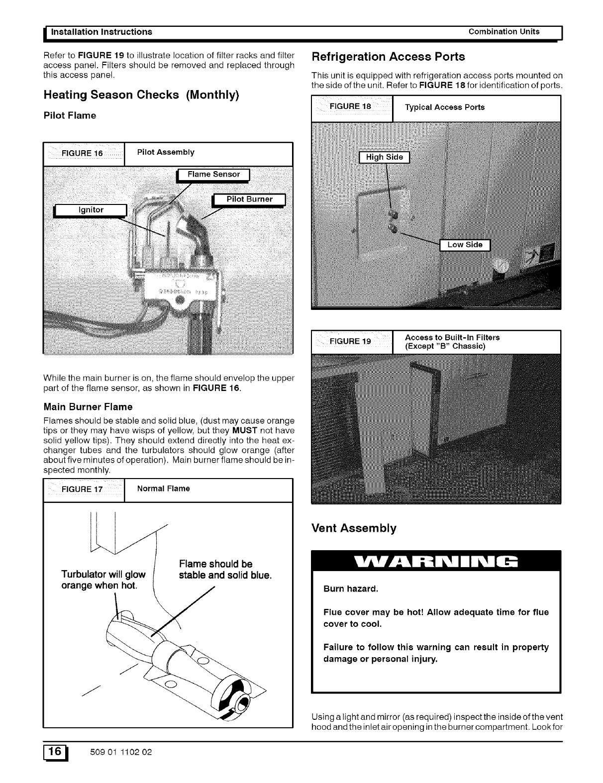
FIGURE i 6 Pilot Assembly
While the main burner is on, the flame should envelop the upper
part of the flame sensor, as shown in FIGURE 16.
Main Burner Flame
Flames should be stable and solid blue, (dust may cause orange
tips or they may have wisps of yellow, but they MUST not have
solid yellow tips). They should extend directly into the heat ex-
changer tubes and the turbulators should glow orange (after
about five minutes of operation). Main burner flame should be in-
spected monthly.
FIGURE Normal Flame
Turbulator will glow
orange when hot.
Flame should be
stable and solid blue.
Combination Units I
Refrigeration Access Ports
This unit is equipped with refrigeration access ports mounted on
the side of the unit. Refer to FIGURE 18 for identification of ports.
Typical Access Ports
I FIGURE i9 Access to Built-In Filters
(Except "B" Chassic)
Vent Assembly
Burn hazard.
Flue cover may be hott Allow adequate time for flue
cover to cool.
Failure to follow this warning can result in property
damage or personal injury.
Using a light and mirror (as required) inspect the inside of the vent
hood and the inlet air opening in the burner compartment. Look for
E_ 50901 110202
I Combination Units Installation Instructions
soot and severe rust or corrosion and any obstructions due to
leaves, spider webs, etc. Clean as required.
Cooling Season Checks (Monthly)
Condenser Coil
Keep the condenser inlet and outlet area clean and free of leaves,
grass clippings or other debris. Grass should be kept short in front
of the condenser inlet. Shrubbery MUST be trimmed back so it is
no closer than 30 inches to unit.
Condensate Drain
Check for condensate drainage. Clean as required.
NOTE: When unit is operating in cooling mode under high humid-
ity ambient conditions, condensate can form in the burner
compartment and may drip from front of the compartment. This
condition is NOT harmful to unit.
Annual Maintenance and Inspection
2. Remove the four screws securing the blower motor hous-
ing. If unit has a support bracket, remove the two screws
securing the bracket.
3. Remove the two red wires attached to the limit switch.
4. Slide entire housing toward you. This will allow easier ac-
cess to the speed tap block, motor, and wires.
5. After access, replace all wires, screws, and connections.
Motor removal and replacement
The blower motor may be replaced while accessing it using meth-
od 1. To replace motor, reach behind blower housing and locate
blower wheel set nut. Loosen set nut, all wires from motor, and
four pins on mounting cradle. Pull motor towards you. To replace
motor, reverse this procedure.
Method 2
This method is required to replace or repair blower wheel, blower
housing, or any unreachable components behind blower assem-
bly.
1. Repeat steps 1 through 4 in method 1.
Electrical shock hazard.
Turn off electric power supply at disconnect switch or
service panel before removing any access or service
panel from unit.
Failure to follow this warning can result in property
damage, personal injury, and/or death.
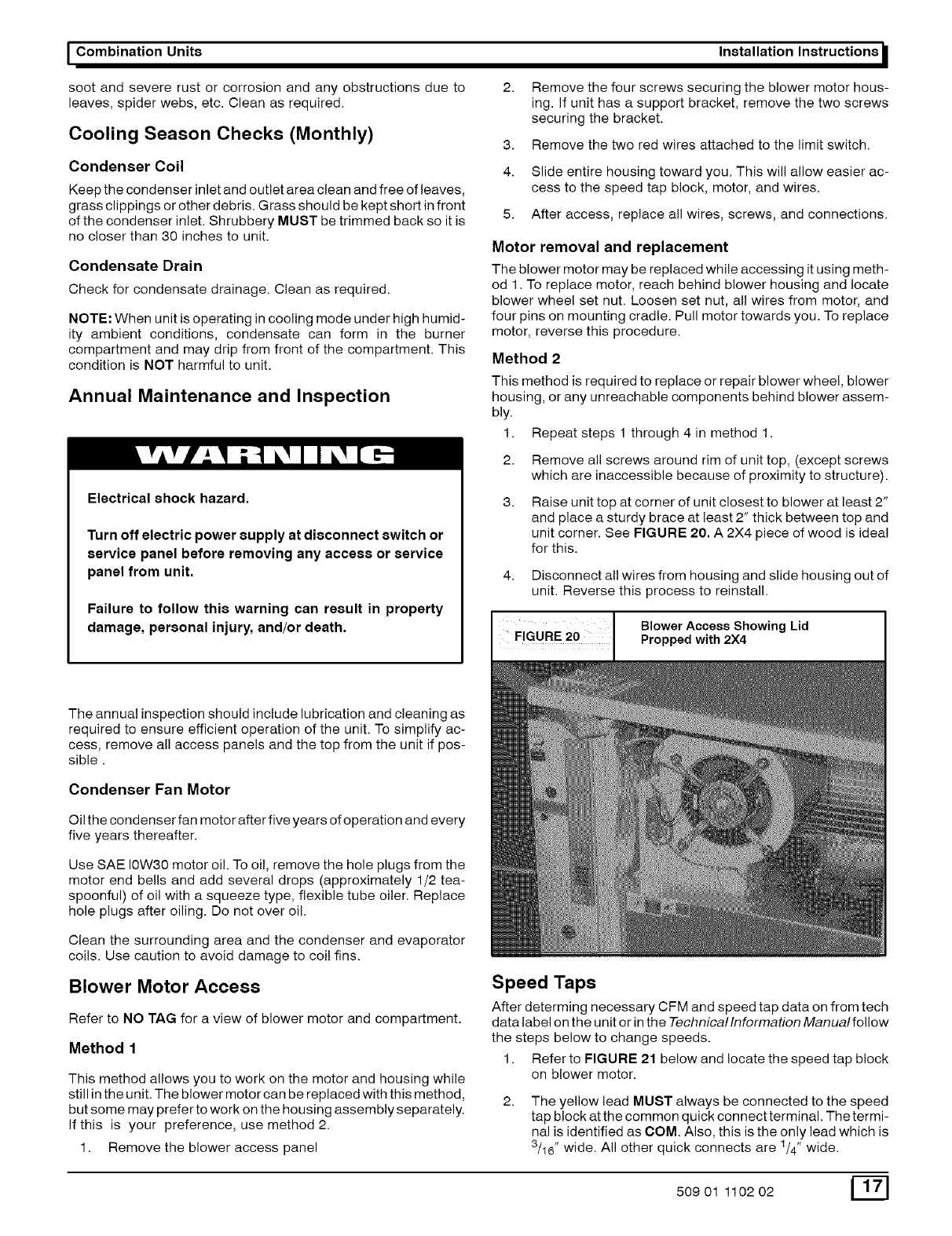
2.
3.
Remove all screws around rim of unit top, (except screws
which are inaccessible because of proximity to structure).
Raise unit top at corner of unit closest to blower at least 2"
and place a sturdy brace at least 2" thick between top and
unit corner. See FIGURE 20. A 2X4 piece of wood is ideal
for this.
4. Disconnect al! wires from housing and slide housing out of
unit. Reverse this process to reinstall.
FIG uRE 20 ProppedBI°werAcceSSwith2x4Sh°wing Lid
The annual inspection should include lubrication and cleaning as
required to ensure efficient operation of the unit. To simplify ac-
cess, remove all access panels and the top from the unit if pos-
sible.
Condenser Fan Motor
Oil the condenser fan motor after five years of operation and every
five years thereafter.
Use SAE 10W30 motor oil. To oil, remove the hole plugs from the
motor end bells and add several drops (approximately 1/2 tea-
spoonful) of oil with a squeeze type, flexible tube oiler. Replace
hole plugs after oiling. Do not over oil.
Clean the surrounding area and the condenser and evaporator
coils. Use caution to avoid damage to coi! fins.
Blower Motor Access
Refer to NO TAG for a view of blower motor and compartment.
Method 1
This method allows you to work on the motor and housing while
still in the unit. The blower motor can be replaced with this method,
but some may prefer to work on the housing assembly separately.
If this is your preference, use method 2.
1. Remove the blower access panel
Speed Taps
After determing necessary CFM and speed tap data on from tech
data label on the unit or in the Technicallnformation Manualfollow
the steps below to change speeds.
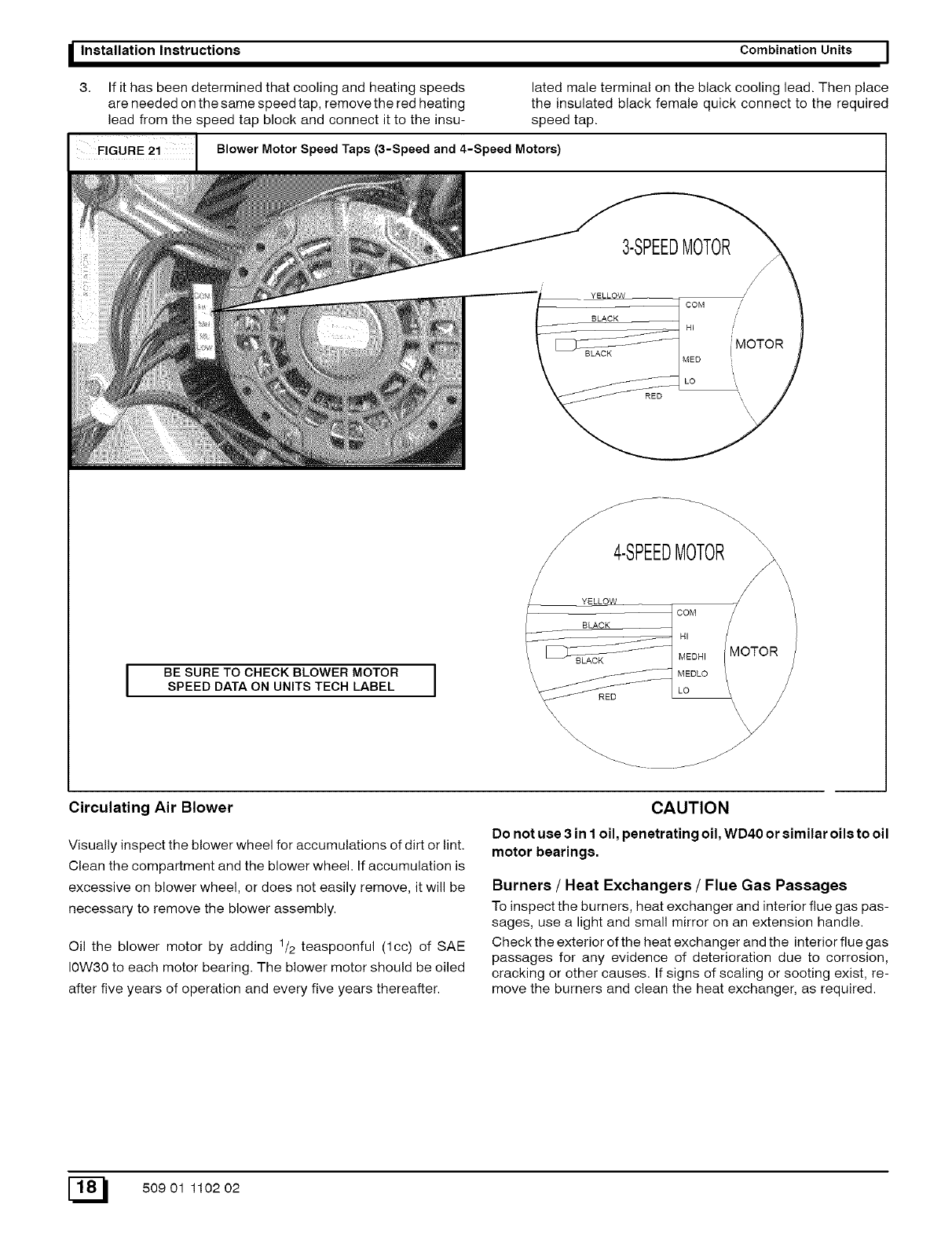
1. Refer to FIGURE 21 below and locate the speed tap block
on blower motor.
The yellow lead MUST always be connected to the speed
tap block atthe common quick connect terminal. The termi-
nal is identified as COM. Also, this is the only lead which is
1 ,
3/16" wide. All other quick connects are /4' wide.
50901 110202 [_[]
_Installation Instructions Combination Units I
3. If it has been determined that cooling and heating speeds lated male terminal on the black cooling lead. Then place
are needed on the same speed tap, remove the red heating the insulated black female quick connect to the required
lead from the speed tap block and connect it to the insu- speed tap.
FIGURE 2i Blower Motor Speed Taps (3-Speed and ,-Speed Motors)
/\\\
/4-SPEEDMOTOR
YELLOW
BLACK
IBE SURE TO CHECK BLOWER MOTOR
SPEED DATA ON UNITS TECH LABEL IRED
\\_\\\\
Circulating Air Blower
Visually inspect the blower wheel for accumulations of dirt or lint.
Clean the compartment and the blower wheel. If accumulation is
excessive on blower wheel, or does not easily remove, it will be
necessary to remove the blower assembly.
Oil the blower motor by adding 1/2 teaspoonful (lcc) of SAE
10W30 to each motor bearing. The blower motor should be oiled
after five years of operation and every five years thereafter.
CAUTION
Do not use 3 in I oil, penetrating oil, WD40 or similar oils to oil
motor bearings.
Burners /Heat Exchangers /Flue Gas Passages
To inspect the burners, heat exchanger and interior flue gas pas-
sages, use a light and small mirror on an extension handle.
Check the exterior of the heat exchanger and the interior flue gas
passages for any evidence of deterioration due to corrosion,
cracking or other causes. If signs of scaling or sooting exist, re-
move the burners and clean the heat exchanger, as required.
50901 110202
I Combination Units
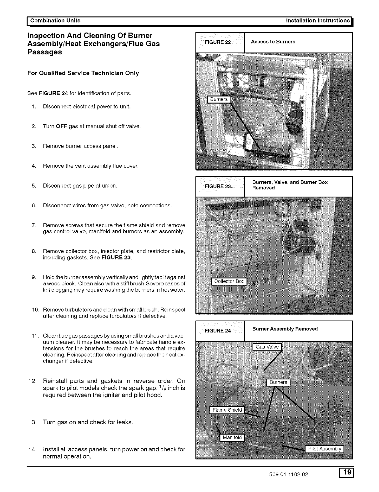
Inspection And Cleaning Of Burner
Assembly/Heat Exchangers/Flue Gas
Passages
Installation Instructions
Access to Burners
For Qualified Service Technician Only
See FIGURE 24 for identification of parts.
1. Disconnect electrical power to unit.
2. Turn OFF gas at manual shut off valve.
3. Remove burner access panel.
4. Remove the vent assembly flue cover.
5. Disconnect gas pipe at union.
6. Disconnect wires from gas valve, note connections.
Burners, Valve, and Burner Box
Removed
7. Remove screws that secure the flame shield and remove
gas control valve, manifold and burners as an assembly.
8. Remove collector box, injector plate, and restrictor plate,
including gaskets. See FIGURE 23.
9. Hold the burner assembly vertically and lightly tap it against
a wood block. Clean also with a stiff brush.Severe cases of
lint clogging may require washing the burners in hot water.
10.
11.
12.
Remove turbulators and clean with small brush. Reinspect
after cleaning and replace turbulators if defective.
Clean flue gas passages by using small brushes and avac-
uum cleaner. It may be necessary to fabricate handle ex-
tensions for the brushes to reach the areas that require
cleaning. Reinspect after cleaning and replace the heat ex-
changer if defective.
Reinstall parts and gaskets in reverse order. On
spark to pilot models check the spark gap. 1/8 inch is
required between the igniter and pilot hood.
13. Turn gas on and check for leaks.
14. Install all access panels, turn power on and check for
normal operation.
EiGURE 24 Burner Assembly Removed
Gas Valve
50901 110202 [_
o"1
o
_o
o
o
o
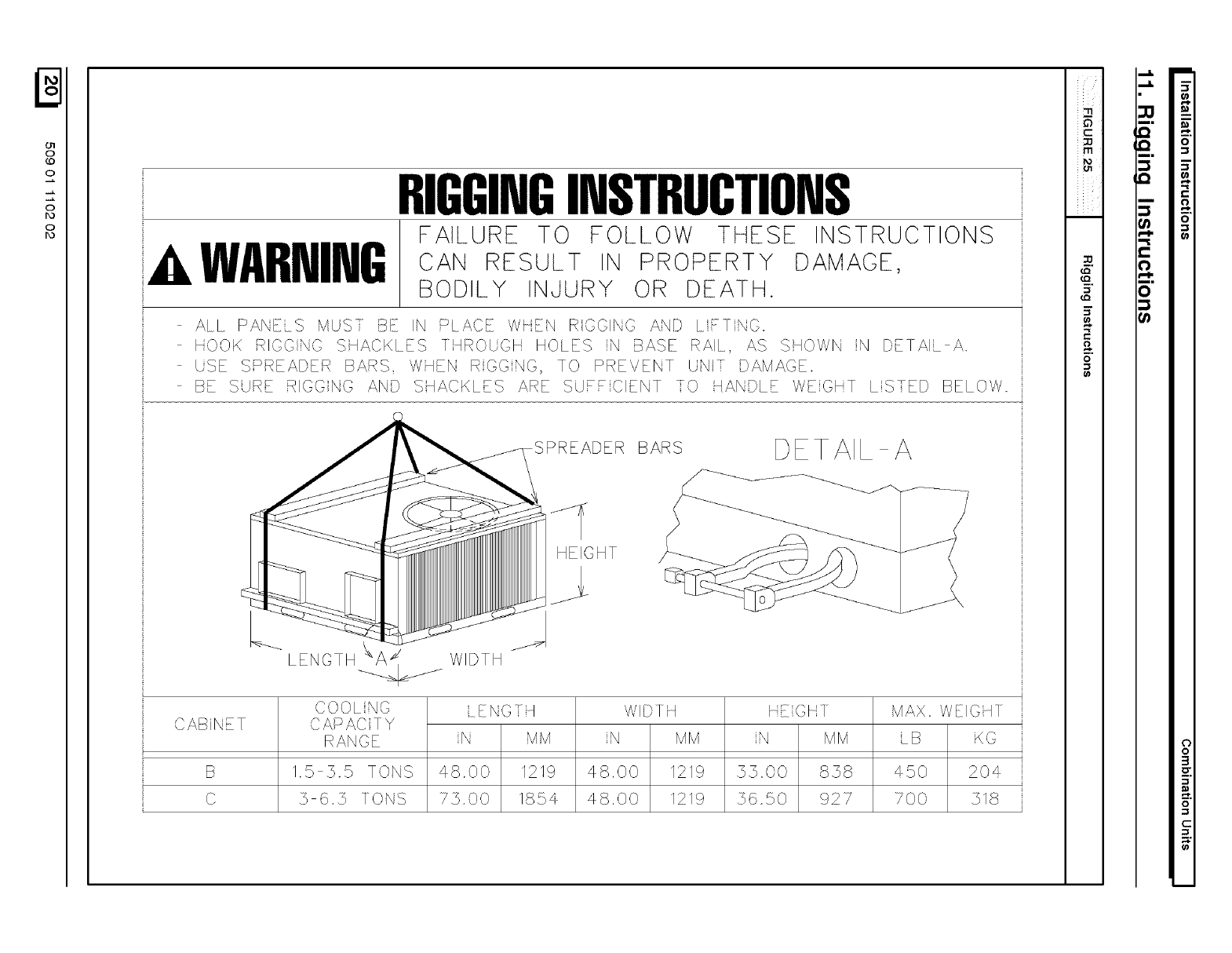
RIGGINGINSTRUCIONS
AWARNING
FAILURE TO FOLLOW THESE INSTRUCTIONS
CAN RESULT IN PROPERTY DAMAGE,
BODILY INJURY OR DEATH.
ALL PANELS MUST I}E IN PI ACE WHEN RGGING AND LFTNO.
HOOK RIGGNG SHACKLES TqROUGH HOLES N BASE RAL, AS SHOWN N DETAIL A.
USE SSREADER BARS, WHEN RGGNG, TO PREVENT UNI:: DAMAGE.
BE SUR" RIGGNG AND SHACKL S ARE SUFFCIENT TO HANDLE WEGHT LS::ED BELOW
BARS DET AlL A
HEIGHT
CAB NET
B
C
LENGTH _/ WIDTH
COOL NO
CAPAC TY
RANGE
1.5 55 TONS
5 6.5 TONS
ENGTq
N MM
4S.OO 1219
75.00 185£
WI/}] H
N MM
48,00 1219
48,00 1219
HEGH]
N MM
35.00 838
3650 927
MAX. WEIGH I
LB KG
450 204
700 518
C
rtl
m.
m.
_t
o
Q
Qo
i•
Q
c
m
I--
am
0
t_
0
o
3
o
C
o)
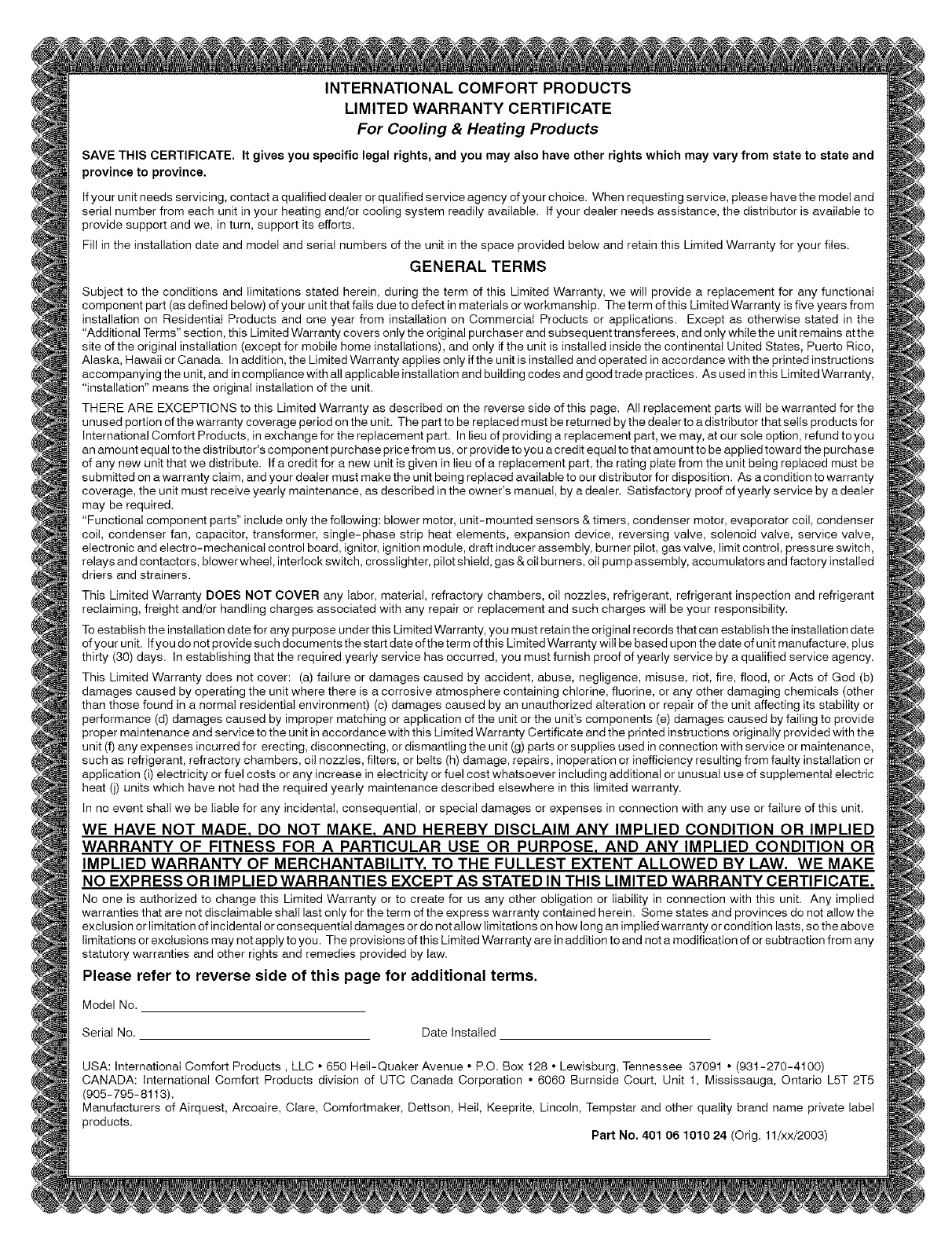
INTERNATIONAL COMFORT PRODUCTS
LIMITED WARRANTY CERTIFICATE
For Cooling & Heating Products
SAVE THIS CERTIFICATE. It gives you specific legal rights, and you may also have other rights which may vary from state to state and
province to province,
If your unit needs servicing, contact a qualified dealer or qualified service agency of your choice. When requesting service, please have the modet and
serial number from each unit in your heating and/or cooling system readily available. If your dealer needs assistance, the distributor is available to
provide support and we, in turn, support its efforts.
Fill in the installation date and model and serial numbers of the unit in the space provided below and retain this Limited Warranty for your files.
GENERAL TERMS
Subject to the conditions and limitations stated herein, during the term of this Limited Warranty, we will provide a replacement for any functional
component part (as defined below) of your unit that fails due to defect in materials or workmanship. The term of this Limited Warranty is five years from
installation on Residential Products and one year from installation on Commercial Products or applications. Except as otherwise stated in the
"Additional Terms" section, this Limited Warranty covers only the original purchaser and subsequent transferees, and onty while the unit remains atthe
site of the original installation (except for mobile home installations), and only if the unit is installed inside the continental United States, Puerto Rico,
Alaska, Hawaii or Canada. In addition, the Limited Warranty applies only ifthe unit is installed and operated in accordance with the printed instructions
accompanying the unit, and in compliance with all applicable installation and building codes and good trade practices. As used inthis Limited Warranty,
"installation" means the original installation of the unit.
TH ERE ARE EXCEPTIONS to this Limited Warranty as described on the reverse side of this page. All replacement parts will be warranted for the
unused portion of the warranty coverage period on the unit. The part to be replaced must be returned by the dealer to a distributor that sells products for
International Comfort Products, in exchange for the replacement part. In lieu of providing areplacement part, we may, at our sole option, refund to you
an amount equal to the distributor's component purchase price from us, or provide to you a credit equal to that amount to be applied toward the purchase
of any new unit that we distribute. If a credit for a new unit is given in tieu of a replacement part, the rating plate from the unit being replaced must be
submitted on a warranty claim, and you r dealer must make the unit being replaced available to our distributor for disposition. As acondition to warranty
coverage, the unit must receive yearly maintenance, as described in the owner's manual, by a dealer. Satisfactory proof of yearly service by a dealer
may be required.
"Functional component parts" include only the following: blower motor, unit-mounted sensors & timers, condenser motor, evaporator coil, condenser
coil, condenser fan, capacitor, transformer, single-phase strip heat elements, expansion device, reversing valve, solenoid valve, service valve,
electronic and electro-mechanical control board, ignitor, ignition module, draft inducer assembly, burner pilot, gas valve, limit control, pressure switch,
relays and contactors, blower wheel, interlock switch, crosslighter, pilot shield, gas & oil burners, oil pump assembly, accumulators and factory installed
driers and strainers.
This Limited Warranty DOES NOT COVER any labor, material, refractory chambers, oit nozzles, refrigerant, refrigerant inspection and refrigerant
reclaiming, freight and/or handling charges associated with any repair or replacement and such charges will be your responsibility.
Toestablish the installation date for any purpose under this Limited Warranty, you must retain the original records that can establish the installation date
ofyour unit. Ifyou donot providesuchdocumentsthe start dateoftheterm ofthis LimitedWarrantywillbe based uponthedate ofunit manufacture, ptus
thirty (30) days. In establishing that the required yearly service has occurred, you must furnish proof of yearly service by a qualified service agency.
This Limited Warranty does not cover: (a) failure or damages caused by accident, abuse, negligence, misuse, riot, fire, flood, or Acts of God (b)
damages caused by operating the unit where there is a corrosive atmosphere containing chlorine, fluorine, or any other damaging chemicals (other
than those found in a normal residential environment) (c) damages caused by an unauthorized alteration or repair of the unit affecting its stability or
performance (d) damages caused by improper matching or application of the unit or the unit's components (e) damages caused by failing to provide
proper maintenance and service to the unit in accordance with this Limited Warranty Certificate and the printed instructions originally provided with the
unit (f) any expenses incurred for erecting, disconnecting, or dismantling the unit (g) parts or supplies used in connection with service or maintenance,
such as refrigerant, refractory chambers, oit nozzles, filters, or belts (h) damage, repairs, inoperation or inefficiency resulting from faulty installation or
application (i) electricity or fuel costs or any increase in electricity or fuel cost whatsoever including additional or unusual use of supplemental electric
heat (j) units which have not had the required yearly maintenance described elsewhere in this limited warranty.
In no event shall we be liable for any incidental, consequential, or special damages or expenses in connection with any use or failure of this unit.
WE HAVE NOT MADE, DO NOT MAKE, AND HEREBY DISCLAIM ANY IMPLIED CONDITION OR IMPLIED
WARRANTY OF FITNESS FOR A PARTICULAR USE OR PURPOSE, AND ANY IMPLIED CONDITION OR
IMPLIED WARRANTY OF MERCHANTABILITY, TO THE FULLEST EXTENT ALLOWED BY LAW. WE MAKE
NO EXPRESS OR IMPLIED WARRANTIES EXCEPT AS STATED IN THIS LIMITED WARRANTY CERTIFICATE.
No one is authorized to change this Limited Warranty or to create for us any other obligation or liability in connection with this unit. Any implied
warranties that are not disctaimable shall last only for the term of the express warranty contained herein. Some states and provinces do not allow the
exclusion or limitation of incidental or consequential damages or do not allow limitations on how long an implied warranty or condition lasts, so the above
limitations or exclusions may not apply to you. The provisions ofthis Limited Warranty are in addition to and not a modification of or subtraction from any
statutory warranties and other rights and remedies provided by law.
Please refer to reverse side of this page for additional terms.
Model No.
Serial No. Date Installed
USA: International Comfort Products, LLC ° 650 Hell-Quaker Avenue ° P.O. Box 128 • Lewisburg, Tennessee 37091 ° (931-270-4100)
CANADA: International Comfort Products division of UTC Canada Corporation • 6060 Burnside Court, Unit 1, Mississauga, Ontario L5T 2T5
(905-795-8113).
Manufacturers of Airquest, Arcoaire, Clare, Comfortmaker, Dettson, Hell, Keeprite, Lincoln, Tempstar and other quality brand name private label
products.
Part No. 401 06 1010 24 (Orig. 11/xx/2003)
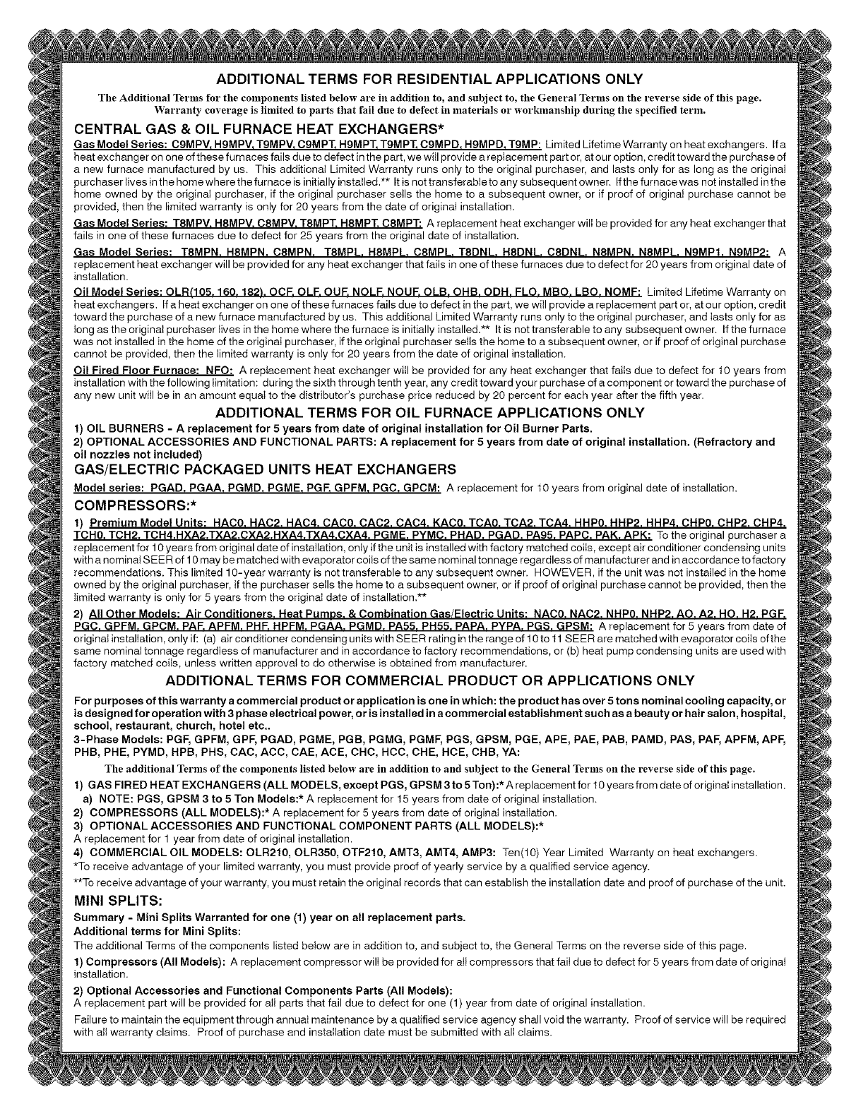
ADDITIONAL TERMS FOR RESIDENTIAL APPLICATIONS ONLY
The Additional Terms for the components listed below are in addition to, and subject to, the General Terms on the reverse side of this page.
Warranty coverage is limited to parts that fail due to defect in lnaterials or workmanship during the specified term.
CENTRAL GAS & OIL FURNACE HEAT EXCHANGERS*
Gas Model Series: C9MPV, HgMPV, TgMPV, CgMPT, H9MPT_TgMPT, C9MPD, H9MPD, TgMP: Limited Lifetime Warranty on heat exchangers. If a
heat exchanger on one of these furnaces fails due to defect in the part, we witl provide a replacement part or, at our option, credit toward the purchase of
a new furnace manufactured by us. This additional Limited Warranty runs only to the original purchaser, and lasts only for as long as the originat
purchaser tives in the home where the furnace is initially installed .** It is not transferable to any subsequent owner. Ifthe furnace was not installed in the
home owned by the original purchaser, if the original purchaser setls the home to a subsequent owner, or if proof of originat purchase cannot be
provided, then the limited warranty is only for 20 years from the date of originat installation.
Gas Model Series: T8MPV. H8MPV. C8MPV. T8MPT. H8MPT. C8MPT: A replacement heat exchanger wilI be provided for any heat exchanger that
fails in one of these furnaces due to defect for 25 years from the original date of installation.
Gas Model Series: T8MPN. H8MPN. C8MPN. T8MPL H8MPL. C8MPL. T8DNL. H8DNL C8DNL N8MPN. N8MPL NgMPI. N9MP2: A
replacement heat exchanger will be provided for any heat exchanger that fails in one of these furnaces due to defect for 20 years from original date of
installation.
Oil Model Series: OLR(105. 160. 182L OCF. OLF. OUE NOLF. NOUF. OLB. OHB. ODH. FLU. MBO. LBO. NOMF: Limited Lifetime Warranty on
heat exchangers. Ifa heatexchangerononeofthesefumacesfailsduetodefectinthepart, wewitl provide a replacement part or, at our option, credit
toward the purchase of a new furnace manufactured by us. This additional Limited Warranty runs only to the original purchaser, and tests only for as
Iong as the original purchaser lives in the home where the furnace is initially installed.** It is not transferable to any subsequent owner. If the furnace
was not installed in the home of the original purchaser, if the original purchaser selts the home to a subsequent owner, or if proof of original purchase
cannot be provided, then the limited warranty is only for 20 years from the date of original installation.
Oil Fired Floor Furnace: NFO: A replacement heat exchanger witl be provided for any heat exchanger that faits due to defect for 10 years from
installation with the following timitatiom during the sixth through tenth year, any credit toward your purchase of a component or toward the purchase of
any new unit wilI be in an amount equal to the distributor's purchase price reduced by 20 percent for each year after the fifth year.
ADDITIONAL TERMS FOR OIL FURNACE APPLICATIONS ONLY
1) OIL BURNERS - A replacement for 5 years from date of original installation for Oil Burner Parts,
2) OPTIONAL ACCESSORIES AND FUNCTIONAL PARTS: A replacement for 5 years from date of original installation. (Refractory and
oil nozzles not included)
GAS/ELECTRIC PACKAGED UNITS HEAT EXCHANGERS
Model series: PGAD, PGAA, PGMD, PGME, PGE GPFM, PGC, GPCM: A replacement for 10 years from original date of installation.
COMPRESSORS:*
1) Premium Model Units: HAC0. HAC2. HAC4. CAC0. CAC2. CAC4. KAC0. TCA0. TCA2. TCA4. HHP0. HHP2. HHP4. CliP0. CliP2. CliP4.
TCH0. TCH2. TCH4.HXA2.TXA2.CXA2.HXA4.TXA4.CXA4. PGME. PYMC. PHAD. PGAD. PA95. PAPC. PAK. APK: To the original purchaser a
replacement for 10 years from original date of installation, only if the unit is installed with factory matched coiis, except air conditioner condensing units
with a nominal SEER of 10 may be matched with evaporator coils of the same nominal tonnage regardless of manufacturer and in accordance to factory
recommendations. This limited 10-year warranty is not transferable to any subsequent owner. HOWEVER, if the unit was not installed in the home
owned by the original purchaser, if the purchaser sells the home to a subsequent owner, or if proof of original purchase cannot be provided, then the
limited warranty is onty for 5 years from the original date of installation.**
2) All Other Models: Air Conditioners. Heat Pumps. & Combination Gas/Electric Units: NAC0. NAC2. NHP0. NHP2. AO. A2. Ha. H2. PGF.
PGC. GPFM. GPCM. PAF. APFM. PHF. HPFM. PGAA. PGMD. PA55. PH55. PAPA. PYPA. PGS. GPSM: A replacement for 5 years from date of
original installation, only if: (a) air conditioner condensing units with SEER rating in the range of 10 to 11 SEER are matched with evaporator coits of the
same nominal tonnage regardless of manufacturer and in accordance to factory recommendations, or (b) heat pump condensing units are used with
factory matched coils, unless written approval to do otherwise is obtained from manufacturer.
ADDITIONAL TERMS FOR COMMERCIAL PRODUCT OR APPLICATIONS ONLY
For purposes of this warranty a commercial product or application is one in which: the product has over 5 tons nominal cooling capacity, or
is designed for operation with 3 phase electrical power, or is installed in a commercial establishment such as a beauty or hair salon, hospital,
school, restaurant, church, hotel etc..
3-Phase Models: PGF, GPFM, GPF, PGAD, PGME, PGB, PGMG, PGMF, PGS, GPSM, PGE, APE, PAE, PAB, PAMD, PAS, PAL=,APFM, APF,
PHB, PHE, PYMD, HPB, PHS, CAC, ACC, CAE, ACE, CHC, HCC, CHE, HCE, CHB, YA:
The additional Terms of the components listed below are in addition to and subject to the General Terms on the reverse side of this page.
1) GAS FIRED HEAT EXCHANGERS (ALL MODELS, except PGS, GPSM 3 to 5 Ton):* A replacement for 10 years from date of original installation.
a) NOTE: PGS, GPSM 3 to 5 Ton Models:* A replacement for 15 years from date of original installation.
2) COMPRESSORS (ALL MODELS):* A replacement for 5 years from date of original installation.
3) OPTIONAL ACCESSORIES AND FUNCTIONAL COMPONENT PARTS (ALL MODELS):*
A replacement for 1 year from date of original installation.
4) COMMERCIAL OIL MODELS: OLR210, OLR350, OTF210, AMT3, AMT4, AMP3: Ten(10) Year Limited Warranty on heat exchangers.
*To receive advantage of your limited warranty, you must provide proof of yearly service by a qualified service agency.
**To receive advantage of your warranty, you must retain the original records that can establish the installation date and proof of purchase of the unit.
MINI SPLITS:
Summary - Mini Splits Warranted for one (1) year on all replacement parts.
Additional terms for Mini Splits:
The additional Terms of the components listed below are in addition to, and subject to, the General Terms on the reverse side of this page.
1) Compressors (All Models): A replacement compressor wili be provided for atI compressors that faiI due to defect for 5 years from date of original
installation.
2) Optional Accessories and Functional Components Parts (All Models):
A replacement part will be provided for alI parts that fail due to defect for one (1) year from date of original installation.
Failure to maintain the equipment through annual maintenance by a qualified service agency shall void the warranty. Proof of service will be required
with ati warranty claims. Proof of purchase and installation date must be submitted with ali claims.
