ICP Furnace/Heater, Gas Manual L0910209
User Manual: ICP ICP Furnace/Heater, Gas Manual ICP Furnace/Heater, Gas Owner's Manual, ICP Furnace/Heater, Gas installation guides
Open the PDF directly: View PDF ![]() .
.
Page Count: 58
90+ GAS FURNACE DIRECT OR NON-DIRECT VENT
Category IV Furnace
*9aPT Two-Stage Heating & Supports
*9MPV 92% Variable Speed, Two-Stage Heating & Supports
Two-Stage Cooling Units
*9MVX 95% Variable Speed, Two-Stage Heating & Supports
Two-Stage Cooling Units
* Denotes Brands (C, H, T)
SAFETY CONSIDERATIONS
Improper installation, adjustment, alteration, service, maintenance, or use can cause explosion, fire, electrical shock, or other
conditions which may cause death, personal injury, or property damage. Consult a qualified installer, service agency, or your
distributor or branch for information or assistance. The qualified installer or agency must use factory-authorized kits or accessories
when modifying this product. Refer to the individual instructions packaged with the kits or accessories when installing.
Follow all safety codes. Wear safety glasses, protective clothing, and work gloves. Use quenching cloth for brazing operations.
Have fire extinguisher available. Read these instructions thoroughly and follow all warnings or cautions included in literature and
attached to the unit. Consult local building codes, the current editions of the National Fuel Gas Code (NFCG) NFPA 54/ANSI
Z223.1, and the National Electrical Code (NEC) NFPA 70.
In Canada refer to the current editions of the National standards of Canada CAN/CSA-B149.1 and .2 Natural Gas and Propane
Installation Codes, and Canadian Electrical Code CSA C22.1.
Recognize safety information. This is the safety-alert symbol z_. When you see this symbol on the unit and in instructions or
manuals, be alert to the potential for personal injury. Understand these signal words; DANGER, WARNING, and CAUTION. These
words are used with the safety-alert symbol. DANGER identifies the most serious hazards which will result in severe personal
injury or death. WARNING signifies hazards which could result in personal injury or death. CAUTION is used to identify unsafe
practices which may result in minor personal injury or product and property damage. NOTE is used to highlight suggestions which
will result in enhanced installation, reliability, or operation.
Before puchasiag this appl{ance,
read important energy cost end
efficiency information available
from your retaJle£
International Comfort Products, LLC
Lewisburg, TN 37091 USA
1. Safe Installation Requirements .................. 5
2. Installation ................................. 6
3. Combustion & Ventilation Air ................... 10
4. Vent & Combustion Air Piping ................... 14
5. Concentric Vent Termination .................... 31
6. Gas Supply and Piping ........................ 34
7. Electrical Wiring ............................. 39
Table of Contents
INSTALLER: Affix these instructions
on or adjacent to the furnace.
CONSUMER: Retain these
instructions for future reference.
8. DuctworkandFilter ......................... 41
9. ChecksandAdjustments ..................... 44
10. FurnaceMaintenance........................ 48
11. Sequenceof Operation& Diagnostics*9MPT ...... 49
12. WiringDiagram*9MPT ....................... 51
13. Sequenceof Operation&Diagnostics*9MPV,*9MVX 52
14. WiringDiagram*9MPV,*9MVX ................. 54
15. ThermostatWiringGuide ..................... 55
ELECTRIC SHOCK HAZARD
Failure to follow this warning
could result in personal injury
and/or death.
Turn Off All Power Before
Servicing.
CARBON MONOXIDE POISONING AND FIRE
HAZARD
Failure to follow this warning could result in
personal injury, death, and/or property dam-
age.
This furnace is not designed for use in mobile
homes, trailers or recreational vehicles.
Portions of the text and tables are reprinted from NFPA 54 /ANSi Z223,1-2006(c_, with permission of National Fire Protection Association, Quincy, MA 02269 and American Gas Association,
Washington, DC 20001. This reprinted material is not the complete and official position of the NFPA or ANSI, on the referenced subject, which is represented only by the standard in its entirety.
Specifications aresubject to change without notice. 440 01 202401 Feb 2009
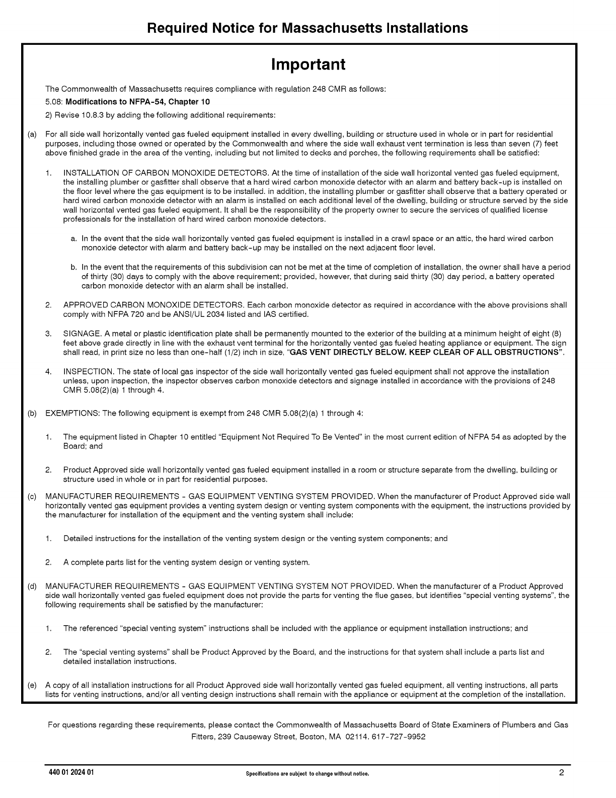
Required Notice for Massachusetts Installations
(a)
Important
The Commonwealth of Massachusetts requires compliance with regulation 248 CMR as follows:
5.08: Modifications to NFPA-54, Chapter 10
2) Revise 10.8.3 by adding the following additional requirements:
For all side wall horizontally vented gas fueled equipment installed in every dwelling, building or structure used in whole or in part for residential
purposes, including those owned or operated by the Commonwealth and where the side wall exhaust vent termination is less than seven (7) feet
above finished grade in the area of the venting, including but not limited to decks and porches, the following requirements shall be satisfied:
1, INSTALLATION OF CARBON MONOXIDE DETECTORS. At the time of installation of the side wall horizontal vented gas fueled equipment,
the installing plumber or gasfitter shall observe that a hard wired carbon monoxide detector with an alarm and battery back-up is installed on
the floor level where the gas equipment is to be installed, in addition, the installing plumber or gasfitter shall observe that a battery operated or
hard wired carbon monoxide detector with an alarm is installed on each additional level of the dwelling, building or structure served by the side
wall horizontal vented gas fueled equipment. It shall be the responsibility of the property owner to secure the services of qualified license
professionals for the installation of hard wired carbon monoxide detectors.
a. In the event that the side wall horizontally vented gas fueled equipment is installed in a crawl space or an attic, the hard wired carbon
monoxide detector with alarm and battery back-up may be installed on the next adjacent floor level.
b. In the event that the requirements of this subdivision can not be met at the time of completion of installation, the owner shall have a period
of thirty (30) days to comply with the above requirement; provided, however, that during said thirty (30) day period, a battery operated
carbon monoxide detector with an alarm shall be installed.
2. APPROVED CARBON MONOXIDE DETECTORS. Each carbon monoxide detector as required in accordance with the above provisions shall
comply with NFPA 720 and be ANSI/UL 2034 listed and IAS certified.
3. SIGNAGE. A metal or plastic identification plate shall be permanently mounted to the exterior of the building at a minimum height of eight (8)
feet above grade directly in line with the exhaust vent terminal for the horizontally vented gas fueled heating appliance or equipment. The sign
shall read, in print size no less than one-half (1/2) inch in size, "GAS VENT DIRECTLY BELOW. KEEP CLEAR OF ALL OBSTRUCTIONS".
4. INSPECTION. The state of local gas inspector of the side wall horizontally vented gas fueled equipment shall not approve the installation
unless, upon inspection, the inspector observes carbon monoxide detectors and signage installed in accordance with the provisions of 248
CMR 5.08(2)(a) 1 through 4.
(b) EXEMPTIONS: The following equipment is exempt from 248 CMR 5.08(2)(a) 1 through 4:
(c)
(d)
(e)
1. The equipment listed in Chapter 10 entitled "Equipment Not Required To Be Vented" in the most current edition of NFPA 54 as adopted by the
Board; and
2. Product Approved side wall horizontally vented gas fueled equipment installed in a room or structure separate from the dwelling, building or
structure used in whole or in part for residential purposes.
MANUFACTURER REQUIREMENTS - GAS EQUIPMENT VENTING SYSTEM PROVIDED. When the manufacturer of Product Approved side wall
horizontally vented gas equipment provides a venting system design or venting system components with the equipment, the instructions provided by
the manufacturer for installation of the equipment and the venting system shall include:
1. Detailed instructions for the installation of the venting system design or the venting system components; and
2. A complete parts list for the venting system design or venting system.
MANUFACTURER REQUIREMENTS - GAS EQUIPMENT VENTING SYSTEM NOT PROVIDED. When the manufacturer of a Product Approved
side wall horizontally vented gas fueled equipment does not provide the parts for venting the flue gases, but identifies "special venting systems", the
following requirements shall be satisfied by the manufacturer:
1. The referenced "special venting system" instructions shall be included with the appliance or equipment installation instructions; and
2. The "special venting systems" shall be Product Approved by the Board, and the instructions for that system shall include a parts list and
detailed installation instructions.
A copy of all installation instructions for all Product Approved side wall horizontally vented gas fueled equipment, all venting instructions, all parts
lists for venting instructions, and/or all venting design instructions shall remain with the appliance or equipment at the completion of the installation.
For questions regarding these requirements, please contact the Commonwealth of Massachusetts Board of State Examiners of Plumbers and Gas
Fitters, 239 Causeway Street, Boston, MA 02114. 617-727-9952
440 01 202401 Specificationsare subject to changewithout notice. 2
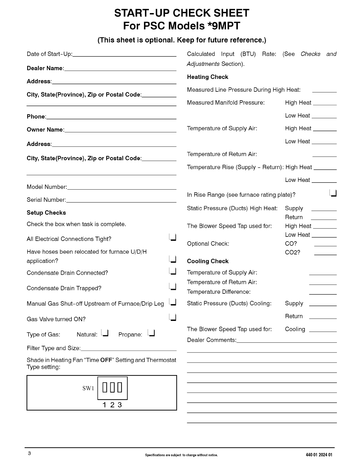
START-UP CHECK SHEET
For PSC Models *9MPT
(This sheet is optional. Keep for future reference.)
Date of Start-Up:
Dealer Name:
Address:
City, State(Province), Zip or Postal Code:
Calculated Input (BTU) Rate: (See Checks
Adjustments Section).
Heating Check
Measured Line Pressure During High Heat:
Measured Manifold Pressure: High Heat
and
Phone:
Owner Name:
Address:
Low Heat
Temperature of Supply Air: High Heat
Low Heat
City, State(Province), Zip or Postal Code: Temperature of Return Air:
Temperature Rise (Supply - Return)' High Heat __
Model Number:
Serial Number:
Setup Checks
Check the box when task is complete.
All Electrical Connections Tight? [U
Have hoses been relocated for furnace U/D/H
application? [U
Condensate Drain Connected? [U
Condensate Drain Trapped? [U
Manual Gas Shut-off Upstream of Furnace/Drip Leg [U
Low Heat
In Rise Range (see furnace rating plate)?
Static Pressure (Ducts) High Heat:
The Blower Speed Tap used for:
Optional Check:
Cooling Check
Temperature of Supply Air:
Temperature of Return Air:
Temperature Difference:
Static Pressure (Ducts) Cooling:
Supply
Return
High Heat
Low Heat
CO?
CO2?
Supply
Gas Valve turned ON? Return
Type of Gas: Natural: [U
Filter Type and Size:
Propane: [U The Blower Speed Tap used for:
Dealer Comments:
Cooling
Shade in Heating Fan "Time OFF" Setting and Thermostat
Type setting:
3 Specifications are subject to change without notice, 440 01 202401
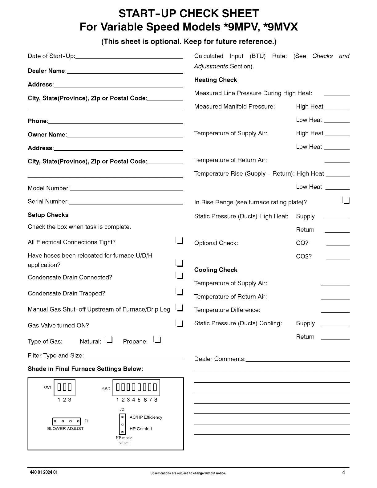
START-UP CHECK SHEET
For Variable Speed Models *9MPV, *9MVX
(This sheet is optional. Keep for future reference.)
Date of Start-Up:
Dealer Name:
Address:
City, State(Province), Zip or Postal Code:
Phone:
Owner Name:
Address:
City, State(Province), Zip or Postal Code:
Model Number:
Serial Number:
Setup Checks
Check the box when task is complete.
All Electrical Connections Tight? Lj
Have hoses been relocated for furnace U/D/H
application? Lj
Condensate Drain Connected? Lj
Condensate Drain Trapped? Lj
Manual Gas Shut-off Upstream of Furnace/Drip Leg Lj
Gas Valve turned ON?
Type of Gas: Natural: Lj Propane: Lj
Filter Type and Size:
Shade in Final Furnace Settings Below:
123 ] 2345 678
J2
lu o o nI ,11 I-_ AC/HPEfficiencySLOWER ADJUST HP Comfort
HP mode
select
Calculated Input (BTU) Rate: (See Checks and
Adjustments Section).
Heating Check
Measured Line Pressure During High Heat:
Measured Manifold Pressure: High Heat
Temperature of Supply Air:
Temperature of Return Air:
Low Heat
High Heat
Low Heat
Temperature Rise (Supply - Return)' High Heat __
Low Heat
In Rise Range (see furnace rating plate)?
Static Pressure (Ducts) High Heat: Supply
Optional Check:
Cooling Check
Temperature of Supply Air:
Temperature of Return Air:
Temperature Difference:
Static Pressure (Ducts) Cooling:
Return
CO?
CO2?
Supply
Return
Dealer Comments:
440 01 202401 Specificationsare subject to changewithout notice. 4
1. Safe Installation Requirements
FIRE, EXPLOSION, AND CARBON MONOXIDE
POISONING HAZARD
Improper adjustment, alteration, service,
maintenance or installation could cause personal
injury, death and/or property damage.
Installation or repairs made by unqualified persons
could result in hazards to you and others.
Installation MUST conform with local codes or, in
the absence of local codes, with codes of all
governmental authorities having jurisdiction.
The information contained in this manual is
intended for use by a qualified service agency that
is experienced in such work, is familiar with all
precautions and safety procedures required in
such work, and is equipped with the proper tools
and test instruments.
NOTE: This furnace is design-certified by the CSA International
(formerly AGA and CGA) for installation in the United States and
Canada. Refer to the appropriate codes, along with this manual, for
proper installation.
•Use only the Type of gas approved for this furnace (see
Rating Plate on unit). Overfiring will result in failure of heat
exchanger and cause dangerous operation. (Furnaces
can be converted to Propane gas with approved kit.)
• Install this furnace only in a location and position as
specified in "Installation" of these instructions.
• Provide adequate combustion and ventilation air to the
furnace as specified in "Combustion and Ventilation Air" of
these instructions.
Combustion products must be discharged outdoors.
Connect this furnace to an approved vent system only, as
specified in "Combustion and Ventilation Air, Horizontal
Venting and Masonry Chimney Venting" of these
instructions.
Never test for gas leaks with an open flame. Use a
commercially available soap solution made specifically for
the detection of leaks to check all connections, as
specified in "Gas Supply and Piping, Final Gas Piping
Check" of these instructions.
• Always install furnace to operate within the furnace's
intended temperature-rise range with a duct system which
has an external static pressure within the allowable range,
as specified in "Technical Support Manual" of these
instructions. See furnace rating plate.
• When a furnace is installed so that supply ducts carry air
circulated by the furnace to areas outside the space
containing the furnace, the return air shall also be handled
by a duct(s) sealed to the furnace casing and terminating
outside the space containing the furnace.
• A gas-fired furnace for installation in a residential garage
must be installed as specified in "Installation
Requirements" of these instructions.
• This furnace is not to be used for temporary heating of
buildings or structures under construction.
• This furnace is NOT approved for installation in
mobile homes, trailers or recreation vehicles,
• Unit MUST be installed so electrical components are
protected from direct contact with water.
Safety Rules
Your unit is built to provide many years of safe and dependable
service providing it is properly installed and maintained. However,
abuse and/or improper use can shorten the life of the unit and
create hazards for you, the owner.
A. The U.S. Consumer Product Safety Commission encourages
installation of carbon monoxide alarms. There can be various
sources of carbon monoxide in a building or dwelling. The
sources could be gas-fired clothes dryers, gas cooking
stoves, water heaters, furnaces, gas-fired fireplaces, wood
fireplaces.
Carbon monoxide can cause serious bodily injury and/or
death. Carbon monoxide or "CO" is a colorless and odorless
gas produced when fuel is not burned completely or when the
flame does not receive sufficient oxygen.
Therefore, to help alert people of potentially dangerous carbon
monoxide levels, you should have a commercially available
carbon monoxide alarm that is listed by a nationally
recognized testing agency in accordance with Underwriters
Laboratories Inc. Standard for Single and Multiple Station
Carbon Monoxide Alarms, ANSI/UL 2034 or the CSA 6.19-01
Residential Carbon Alarming Devices installed and
maintained in the building or dwelling concurrently with the
gas-fired furnace installation (see Note below). The alarm
should be installed as recommended by the alarm
manufacturer's installation instructions.
B. There can be numerous sources of fire or smoke in a building
or dwelling. Fire or smoke can cause serious bodily injury,
death, and/or property damage. Therefore, in order to alert
people of potentially dangerous fire or smoke, you should have
fire extinguisher and smoke alarms listed by Underwriters
Laboratories installed and maintained in the building or
dwelling (see Note below).
Note: The manufacturer of your furnace does not test any alarms
and makes no representations regarding any brand or type
of alarms.
C.
1.
2.
To ensure safe and efficient operation of your unit, you should
do the following:
Thoroughly read this manual and labels on the unit. This
will help you understand how your unit operates and the
hazards involved with gas and electricity.
Do not use this unit if any part has been under water.
Immediately call a qualified service technician to inspect the
unit and to replace any part of the control system and any gas
control which has been under water.
3. Never obstruct the vent grilles, or any ducts that provide
air to the unit. Air must be provided for proper combustion
and ventilation of flue gases.
• Seal around supply and return air ducts.
• Install correct filter type and size.
440 01 202401 Specificationsare subject to changewithout notice. 5
FrozenWaterPipeHazard
WATER DAMAGE TO PROPERTY HAZARD
Failure to protect against the risk of freezing may
result in property damage,
Do not leave your home unattended for long periods
during freezing weather without turning off water
supply and draining water pipes or otherwise
protecting against the risk of frozen pipes and
resultant damage.
Your furnace is designed solely to provide a safe and comfortable
living environment. The furnace is NOT designed to ensure that
water pipes will not freeze. It is equipped with several safety
devices that are designed to turn the furnace off and prevent it from
restarting in the event of various potentially unsafe conditions.
If your furnace remains off for an extended time, the pipes in your
home could freeze and burst, resulting in serious water damage.
If the structure will be unattended during cold weather you should
take these precautions.
1. Turn off the water supply to the structure and drain the water
lines if possible and add an antifreeze for potable water to
drain traps and toilet tanks. Open faucets in appropriate
areas.
-or-
2.
3.
Have someone check the structure frequently during cold
weather to make sure it is warm enough to prevent pipes
from freezing. Instruct them on a service agency to call to
provide service, if required.
-or-
Install a reliable remote sensing device that wilt notify
somebody of freezing conditions within the home.
Winter Shutdown
If you go away during the winter months and do not leave the heat
on in your home, the plastic transition box and the condensate trap
on the furnace must be protected from freeze damage.(See
Figure 11 trough Figure 20)
1. Disconnect the 5/8" (15.9mm) OD rubber hose from the vent
drain fitting that is located downstream of the combustion
blower. Insert a funnel into the hose and pour four(4) ounces
of sanitary type (RV) antifreeze into the condensate trap.
Reconnect the 5/8" (15.9mm) OD rubber hose to the stub on
the vent drain fitting. Secure with the hose clamp.
2. Disconnect the 3/4" (19.1mm) OD rubber hose from the
condensate trap. Insert a funnel into the hose and and pour
four(4) ounces of sanitary type (RV) antifreeze into the
plastic Transition box. Squeeze the hose together near the
end and quickly reconnect the 3/4" (19.1mm) OD rubber
hose to the stub on the condensate trap. Secure with the
hose clamp.
When you return home, your furnace will be ready to start, as it is
not necessary to drain the antifreeze from the furnace.
2. Installation
CARBON MONOXIDE POISONING HAZARD
Failure to properly vent this furnace or other
appliances could result in personal injury or death.
This furnace can NOT be common vented or
connected to any type B, BW or L vent or vent
connector, nor to any portion of a factory-built or
masonry chimney. If this furnace is replacing a
previously common-vented furnace, it may be
necessary to resize the existing vent and chimney
to prevent oversizing problems for the other
remaining appliance(s). See Venting and
Combustion Air Check in the Combustion &
Ventilation Air section. This furnace MUST be
vented to the outside.
2. If furnace is a replacement, it is usually best to install the
furnace where the old one was. Choose the location or
evaluate the existing location based upon the minimum
clearance and furnace dimensions (Figure 4).
CARBON MONOXIDE POISONING HAZARD.
Failure to follow this warning could result in
personal injury or death.
Do NOT operate furnace in a corrosive atmosphere
containing chlorine, fluorine or any other damaging
chemicals, which could shorten furnace life.
Refer to Combustion & Ventilation Air section,
Contaminated Combustion Air for combustion air
evaluation and remedy.
InstallationPositions
This furnace can be installed in an upflow, horizontal (either left or
right) or downflow airflow position. DO NOT install this furnace on
its back. For the upflow position, the return air ductwork can be
attached to either the left or right side panel and/or the bottom. For
horizontal and downflow positions, the return air ductwork must be
attached to the bottom. The return air ductwork must never be
attached to the back of the furnace.
Location and Clearances
Refer to Figure 1 or Figure 2 for typical installation and
basic connecting parts required. Refer to Figure 3 for
typical horizontal direct vent installation and basic
connecting parts required. Supply and return air plenums
and duct are also required.
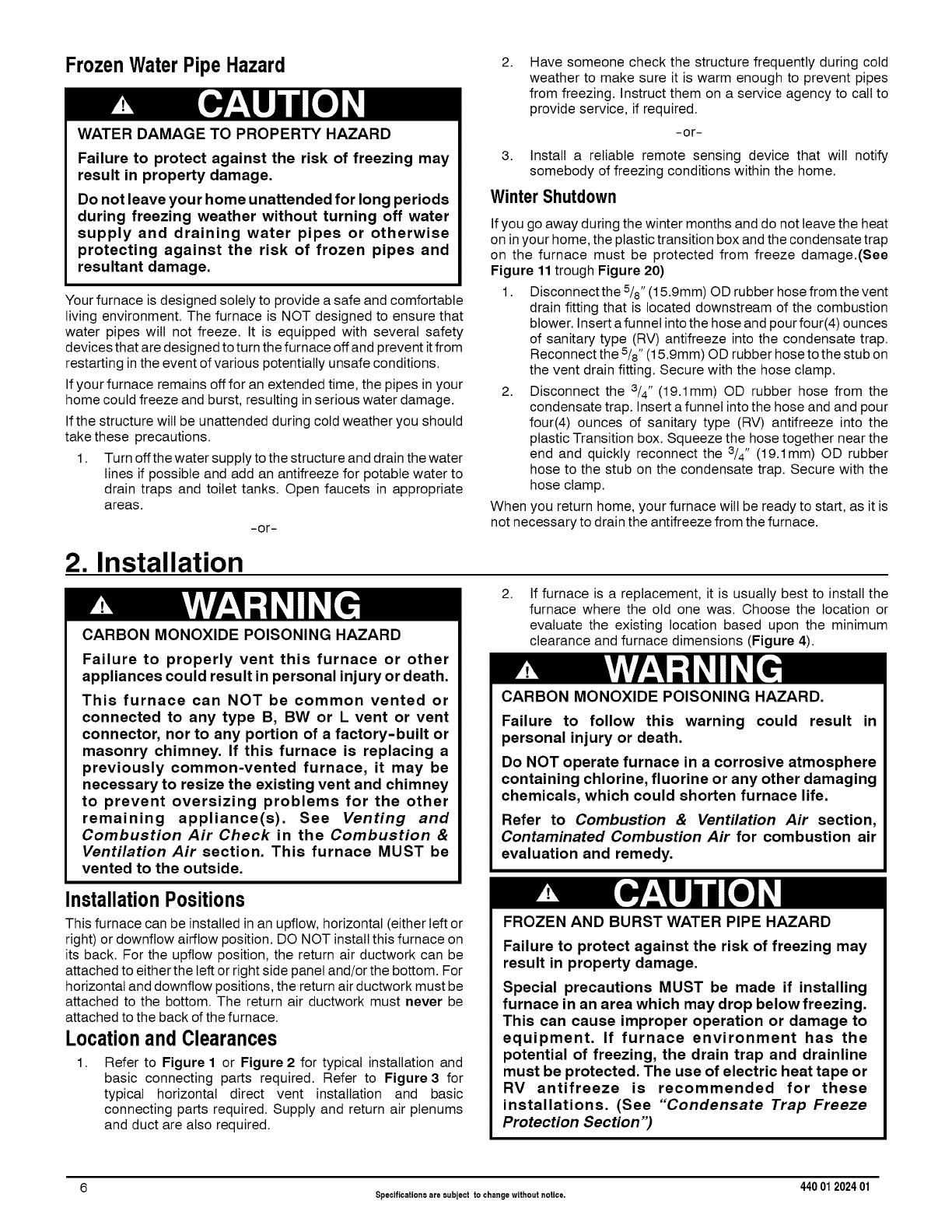
FROZEN AND BURST WATER PIPE HAZARD
Failure to protect against the risk of freezing may
result in property damage.
Special precautions MUST be made if installing
furnace in an area which may drop below freezing.
This can cause improper operation or damage to
equipment. If furnace environment has the
potential of freezing, the drain trap and drainline
must be protected. The use of electric heat tape or
RV antifreeze is recommended for these
installations. (See "Condensate Trap Freeze
Protection Section")
6 Specifications are subject to changewithout notice. 440 012024 01
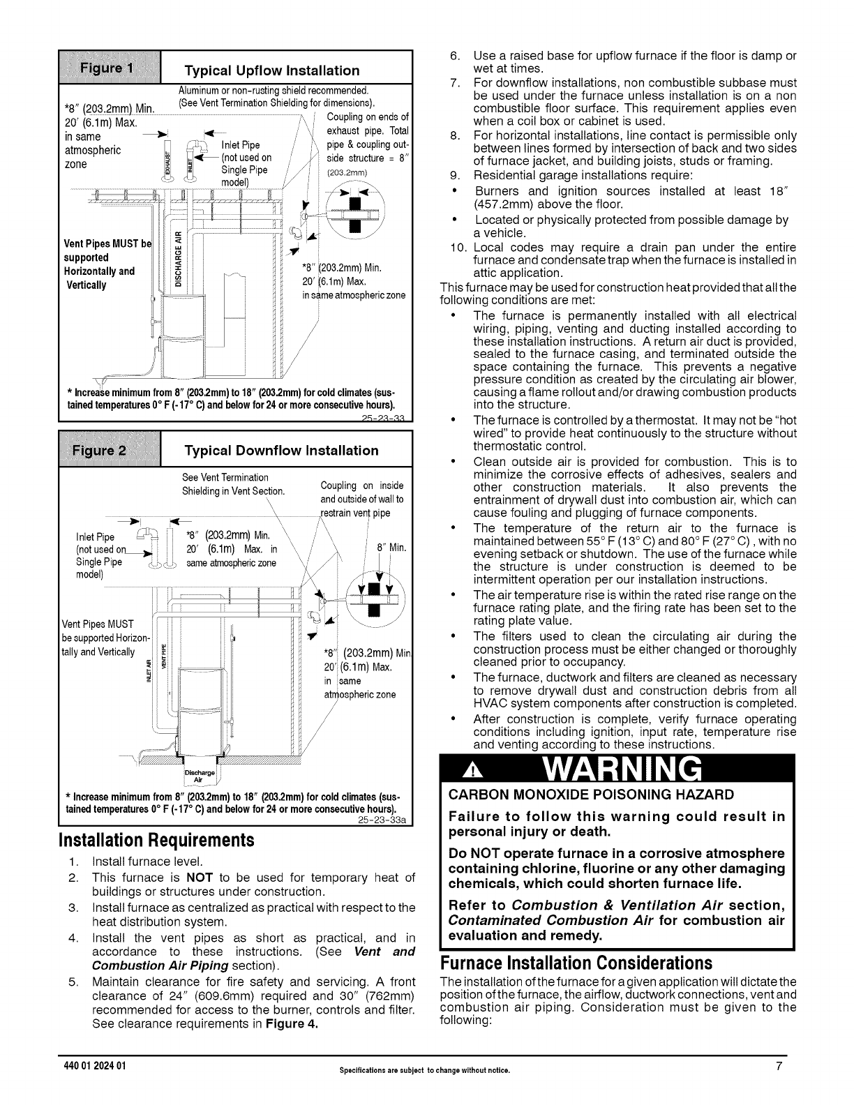
Typical Upflow Installation
VentPipesMUST be
supported
Horizontallyand
Vertically
Aluminumornon-rustingshieldrecommended.
*8.......... (SeeVentTerminationShieldingfordimensions)
tzu_ zmm] M n _ '
20' t6imi Max....................................................................................................................................................................;,\ /Couplingonendsof
\" J " _i,_ /_' exhaustppe Tota
in same ,,
J._ InletPipe pipe&couplingout-
atmospheric ...._ (not usedon
zone I_i. ../side structure = 8"
%SinglePipe (203.2mm)
_" model) /
"8" i203.2mm)Min.
20' (6.1m)Max.
insameatmosphericzone
* Increaseminimumfrom8"(203.2mm)to18"(203.2mm)forcoldclimates(sus-
tainedtemperatures0°F(-17° C)andbelowfor24ormoreconsecutivehours).
25-23-33
Typical Downflow Installation
SeeVentTermination
ShieldinginVentSection.
\
\ .restrainvent
InletPipe ,Y?]_ ] "8" (20&2mm)Min. \, xx
(not usedon_ i 20' (6.1m) Max. in \, //
Single Pipe i_i>_,!_ same atmospheric zone /'
model)
ii"
VentPipesMUST i _ ;i
besupportedHorizon-i
tally and Vertically i i_ i i
z_i
Coupling on inside
andoutsideofwallto
pipe
8" Min.
"8" (203.2mm)Min
20';:(6.1m)Max.
in same
/?ospheric zone
:;Discharge i
_r y
* Increaseminimumfrom8"(203.2mm)to18" (203.2mm)forcoldclimates(sus-
tainedtemperatures0°F(-17°C)andbelowfor24ormoreconsecutivehours).
25-23-33a
InstallationRequirements
1. Install furnace level.
2. This furnace is NOT to be used for temporary heat of
buildings or structures under construction.
3. Install furnace as centralized as practical with respect to the
heat distribution system.
4. Install the vent pipes as short as practical, and in
accordance to these instructions. (See Vent and
Combustion Air Piping section).
5. Maintain clearance for fire safety and servicing. A front
clearance of 24" (609.6mm) required and 30" (762mm)
recommended for access to the burner, controls and filter.
See clearance requirements in Figure 4.
6. Use a raised base for upflow furnace if the floor is damp or
wet at times.
7. For downflow installations, non combustible subbase must
be used under the furnace unless installation is on a non
combustible floor surface. This requirement applies even
when a coil box or cabinet is used.
8. For horizontal installations, line contact is permissible only
between lines formed by intersection of back and two sides
of furnace jacket, and building joists, studs or framing.
9. Residential garage installations require:
• Burners and ignition sources installed at least 18"
(457.2mm) above the floor.
• Located or physically protected from possible damage by
a vehicle.
10. Local codes may require a drain pan under the entire
furnace and condensate trap when the furnace is installed in
attic application.
This furnace may be used for construction heat provided that all the
following conditions are met:
• The furnace is permanently installed with all electrical
wiring, piping, venting and ducting installed according to
these installation instructions. A return air duct is provided,
sealed to the furnace casing, and terminated outside the
space containing the furnace. This prevents a negative
pressure condition as created by the circulating air blower,
causing a flame rollout and/or drawing combustion products
into the structure.
• The furnace is controlled by a thermostat. It may not be "hot
wired" to provide heat continuously to the structure without
thermostatic control.
• Clean outside air is provided for combustion. This is to
minimize the corrosive effects of adhesives, sealers and
other construction materials. It also prevents the
entrainment of drywall dust into combustion air, which can
cause fouling and plugging of furnace components.
• The temperature of the return air to the furnace is
maintained between 55° F (13 ° C) and 80 ° F (27 ° C), with no
evening setback or shutdown. The use of the furnace while
the structure is under construction is deemed to be
intermittent operation per our installation instructions.
• The air temperature rise is within the rated rise range on the
furnace rating plate, and the firing rate has been set to the
rating plate value.
• The filters used to clean the circulating air during the
construction process must be either changed or thoroughly
cleaned prior to occupancy.
• The furnace, ductwork and filters are cleaned as necessary
to remove drywall dust and construction debris from all
HVAC system components after construction is completed.
• After construction is complete, verify furnace operating
conditions including ignition, input rate, temperature rise
and venting according to these instructions.
CARBON MONOXIDE POISONING HAZARD
Failure to follow this warning could result in
personal injury or death.
Do NOT operate furnace in a corrosive atmosphere
containing chlorine, fluorine or any other damaging
chemicals, which could shorten furnace life.
Refer to Combustion & Ventilation Air section,
Contaminated Combustion Air for combustion air
evaluation and remedy.
FurnaceInstallationConsiderations
The installation ofthe furnace for a given application will dictate the
position ofthe furnace, the airflow, ductwork connections, vent and
combustion air piping. Consideration must be given to the
following:
440 01 202401 Specificationsare subject to changewithout notice. 7
Condensate Trap and Drain Lines
The supplied condensate trap must be attached to the furnace side
panel on either the left or right side. For horizontal installations, the
drain trap is vertically attached to the side panel below the furnace.
A minimum clearance of 6" (152.4mm) below the furnace is
required for the condensate trap. Downward slope of the
condensate drain line from the condensate trap to the drain
location must be provided. Adequate freeze protection of the drain
trap and the drain line must be provided. See "Condensate Drain
Trap" section for further details.
Leveling
Proper leveling of the furnace must be provided to insure proper
drainage of the condensate from the furnace. The furnace must be
level to within 1/4" (6.4mm) from front to back and from side to side
for upflow and downflow installations or top to bottom for horizontal
installations.
Vent and CombustionAir Connections
For venting information literature, call 931.270.4100 with the
complete model and serial number of the furnace.
Special Venting Requirements for Installations in Canada
Installation in Canada must conform to the requirements of CSA
B149 code. Vent systems must be composed of pipe, fittings,
cements, and primers listed to ULC $636. The special vent
fittings and accessory concentric vent termination kits and
accessory external drain trap have been certified to ULC $636
for use with those IPEX PVC vent components which have
been certified to this standard. In Canada, the primer and
cement must be of the same manufacturer as the vent system -
IPEX System 636, PVC/CPVC Primer, Purple Violet for Flue
Gas Venting and IPEX System 636(1)TM,PVC Cement for Flue
Gas Venting, rated Class IIA, 65 deg C. must be used with this
venting system - do not mix primers and cements from one
manufacturer with a vent system from a different manufacturer.
Follow the manufacturer's instructions in the use of primer and
cement and never use primer or cement beyond its expiration
date.
The safe operation, as defined by ULC $636, of the vent
system is based on following these installation instructions, the
vent system manufacturer's installation instructions, and proper
use of primer and cement. All fire stop and roof flashing used
with this system must be UL listed material. Acceptability under
Canadian standard CSA B149 is dependent upon full
compliance with all installation instructions. Under this
standard, it is recommended that the vent system be checked
once a year by qualified service personnel.
The authority having jurisdiction (gas inspection authority,
municipal building department, fire department, etc) should be
consulted before installation to determine the need to obtain a
permit.
Consignes sp6ciales pour rinstallation de ventillation au
Canada
L'installation faite au Canada dolt se conformer aux exigences
du code CSA B149. Ce syst_me de ventillation dolt se
composer de tuyaux, raccords, ciments et appr_ts conformes
au ULC $636. La tuyauterie de ventillation des gaz, ses
accessoires, le terminal concentrique mural ainsi que
I'ensemble du drain de condensat exterieur ont et6 certifies
ULCS 636 pour I'application des composantes IPEX PVC qui
sont certifiees & ce standard. Au Canada I'appr_t et le ciment
doivent _tre du m_me manufacturier que le syst_me de
ventillation - IPEX Systeme 636, Appr_t PVC/CPVC. Mauve
Violette pour conduit en evacuation des gaz et IPEX Systeme
636(1)TM,ciment pour PVC pour conduit en evacuation des gaz,
6val'u_ CLASSE IIA, 65 deg. C. doit _tre utilise avec ce
systeeme d'evacuation - ne pas melanger I'appr_t et le ciment
d'un manufacturier avec le syst_me de ventillation d'un autre
manufacturier. Bien suivre les indications du manufacturier Iors
de I'utilisation de I'appr_t et du ciment et ne pas utiliser ceux-ci
si la date d'expiration est atteinte.
L'operation securitaire, tel que definit par ULC $636, du
systeme de ventilation est base sur les instructions d'installation
suivantes, ainsi que I'usage approprie de I'appr_t et ciment.
Tout arret feu et solin de toit utilises avec ce systeme doivent
_tre des materiaux listes UL. L'acceptation du standard
Canadien CSA B419 est directement relie & I'installation
conforme aux instructions ci- haut mentionnees. Le standard
Canadien recommande I' inspection par un personel qualifie et
ce, une fois par annee.
Les autoritees ayant juridiction (inspecteurs de gas, inspecteurs
en b&timents, departement des incendies, etc) devraient _tre
consultees avant I'instatlation afin de determiner si un permis
est requis.
(1) System 636 is a trademark of IPEX Inc.
On the Dual Certified furnace, the vent and combustion air pipes
attach to the furnace through the top panel for the upflow and
horizontal installations. For the downflow installation, the vent and
combustion air pipes attach to the furnace through the alternate
locations on the furnace side panels.
Note: On the Direct Vent furnace, the vent pipe attaches to the
furnace through the side panels. The combustion air pipe attaches
to the top panel or to the alternate location on the side panel.
On the Single Pipe furnace, the vent pipe attaches to the furnace
through the furnace side panels.
Note: Repositioning of the combustion blower is required for the
vent pipe connection to the furnace through the "right side" panel.
See "Vent and Combustion Air Piping" section for further details.
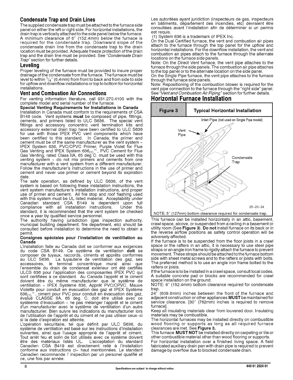
HorizontalFurnaceInstallation
Typical Horizontal Installation
This furnace can be installed horizontally in an attic, basement,
crawl space, alcove, or suspended from a ceiling ina basement or
utility room (See Figure 3). Do not install furnace on its back or in
the reverse airflow positions as safety control operation will be
adversely affected.
If the furnace is to be suspended from the floor joists in a crawl
space or the rafters in an attic, it is necessary to use steel pipe
straps or an angle ironframe to rigidly attach the furnace to prevent
movement. These straps should be attached to the furnace bottom
side with sheet metal screws and to the rafters or joists with bolts.
The preferred method is to use an angle iron frame bolted to the
rafters or joists.
Ifthe furnace is to be installed in a crawl space, consult local codes.
A suitable concrete pad or blocks are recommended for crawl
space installation on the ground.
NOTE: 6" (152.4mm) bottom clearance required for condensate
trap.
24" (609.6mm) inches between the front of the furnace and
adjacent construction or other appliances MUST be maintained for
service clearance. [30" (762mm) inches is required to remove
furnace].
Keep all insulating materials clear from Iouvered door. Insulating
materials may be combustible.
The horizontal furnaces may be installed directly on combustible
wood flooring or supports as long as all required furnace
clearances are met. See Figure 3.
This furnace MUST NOT be installed directly on carpeting or tile or
other combustible material other than wood flooring or supports.
For horizontal installation over a finished living space. A field
fabricated auxiliary drain pan with drain pipe is required to prevent
damage by overflow due to blocked condensate drain.
8 Specifications are subject to changewithout notice. 440 012024 01
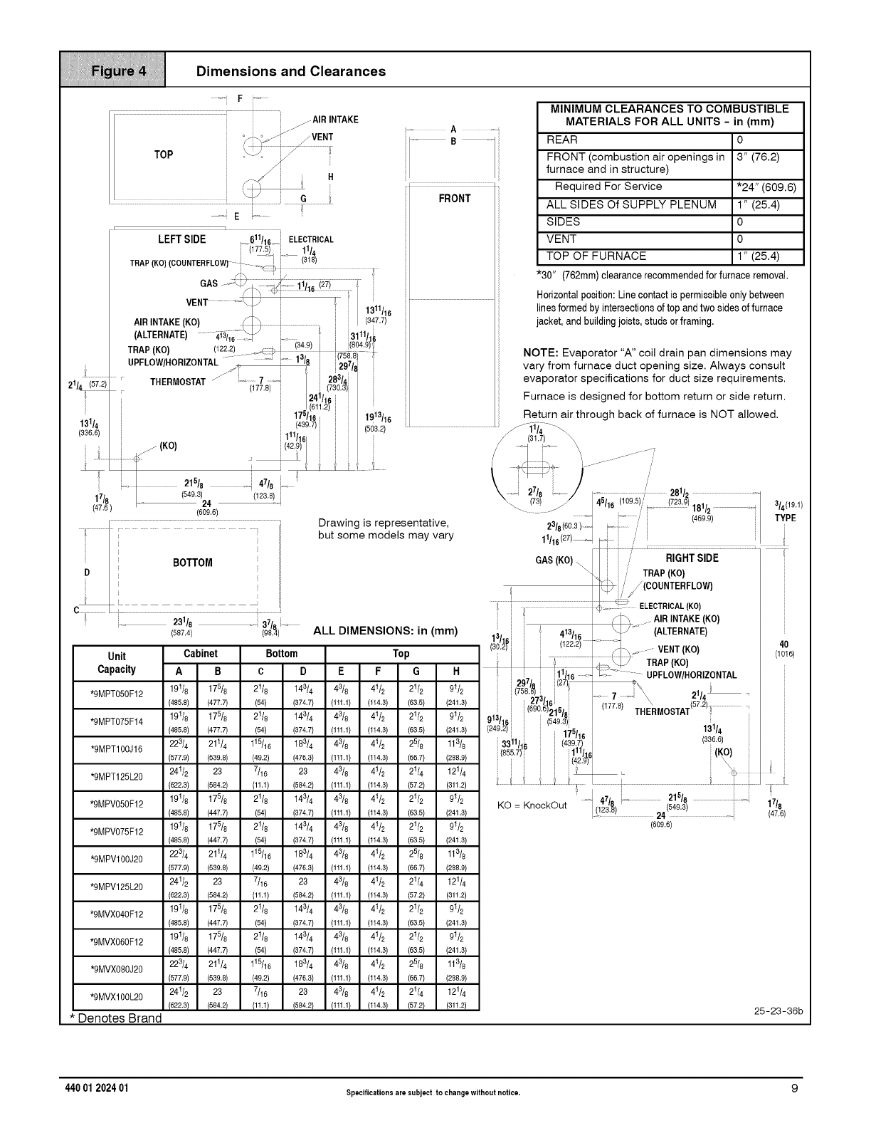
Dimensions and Clearances
.........Fi.........
.................................................................................i i i .......A,R,NT KE
TOP ...................................I
a
• i
LEFTSIDE +8611116,iELECTRICAL
[ ii775) i 11
-_L__,_ '_/
TRAP(COU.TE+LO ...............................
GAS ........................i ::
VENT ............. \/:' i / 1_11/
+i i lS
ARNTAKE (KO) S _ .................i..............................i / (347'7)
(ALTERNATE) .... 4Y£i16 _J! i .ii+,;_ 11/1L
TRAP(KO) (122.2) ' +; b _ !3::P) i '%_
UPFLOW/HORIZONTAL.... _+ +" +' t'_!8 + t_297 '
...... THERMOSTAT f" i..........7.......i 28314 i
21/_ _ 177,8 i(730.3) :
i/!4 Vt6t _
i J 611.2)
i17=/6 i 1913116
13114 i i (439 7) i (603.2)
(336.6) ; i 111/1 i
j(KO) 42,9 t
+; .................+++ ++ _ i+ :
,,21618 ++ 47/8., +
t7/8 | (849,3)24 (12331i
(47,6) (609,6)
D_i
-A+=i
B
FRONT
Drawing is representative,
but some models may vary
ALL DIMENSIONS: in (mm)
Unit
Capacity
*RMPT050F12
*RMPT075F14
*9MPT100J16
*RMPT125L20
*9MPV050F12
*9MPV075F12
*RMPVl00J20
*RMPV125L20
*9MVX040F12
*9MVX060F12
*RMVX080J20
*RMVX100L20
* Denotes Brand
Cabinet Bottom
AB c D
19t/8 175/8 2t/8 143/4
(485.8} (477.7) (54) (374,7)
191/8 17518 21/8 143/4
(485.8) (477.7) (54) (374,7)
223/4 21114 115/16 18314
(577.9) (539.8) (49.2) (476,3)
241/2 23 7/16 23
(522.3) (584.2) (11.1) (584,2)
191/8 17518 21/8 14314
(485.8) (447.7) (54) (374,7)
191/8 17518 21/8 143/4
(485.8) (447.7) (54) (374,7)
223/4 21114 115/16 18314
(577.9) (539.8) (49.2) (476,3)
241/2 23 7/16 23
(522.3) (584.2) (11.1) (584,2)
191/8 17518 21/8 14314
(485.8) (447.7) (54) (374,7)
191/8 17518 21/8 143/4
(485.8) (447.7) (54) (374,7)
223/4 21114 115/16 18314
(577.9) (539.8) (49.2) (476,3)
241/2 23 7/16 23
(522.3) (584.2) (11.1) (584,2)
Top
EFGH
43/8 4112 21/2 9112
(tt1,1) (tt4.3) (6&5) (241.3)
4318 4112 21/2 9112
(tt1,1) (tt4.3) (6&5) (241.3)
43/8 4t12 25/8 113/8
(tt1,1) (tt4.3) (56,7) (288.9)
43/8 4t/2 21/4 12114
(tt1,1) (tt4.3) (57,2) (311.2)
43/8 4t/2 21/2 9t/2
(tt1,1) (tt4.3) (5&5) (241.3)
43/8 4t/2 21/2 9t/2
(tt1,1) (tt4.3) (5&5) (241.3)
43/8 4t/2 25/8 113/8
(tt1,1) (tt4.3) (56,7) (288.9)
43/8 4t/2 21/4 12114
(tt1,1) (tt4.3) (57,2) (311.2)
43/8 4t/2 21/2 9t/2
(tt1,1) (tt4.3) (5&5) (241.3)
43/8 4t/2 21/2 9t/2
(tt1,1) (tt4.3) (5&5) (241.3)
43/8 4t/2 25/8 113/8
(tt1,1) (tt4.3) (56,7) (288.9)
43/8 4t/2 21/4 12114
(tt1,1) (tt4.3) (57.2) (311.2)
MINIMUM CLEARANCES TO COMBUSTIBLE
MATERIALS FOR ALL UNITS -in (mm)
REAR 0
FRONT (combustion air openings in 3" (76.2)
furnace and in structure)
Required For Service
ALL SIDES Of SUPPLY PLENUM
SIDES
VENT
TOP OF FURNACE
"30" (762mm)clearancerecommendedforfurnaceremoval.
Horizontalposition:Linecontactis permissibleonly between
linesformed byintersectionsof top andtwo sidesof furnace
jacket,and buildingjoists,studs orframing.
"24" (609.6)
1" (25.4)
0
0
1" (25.4)
NOTE: Evaporator "A" coil drain pan dimensions may
vary from furnace duct opening size. Always consult
evaporator specifications for duct size requirements.
Furnace is designed for bottom return or side return.
Return air through back of furnace is NOT allowed.
17/8
(47.6)
25-23-36b
181/2
(469,9)
/
/RIGHT SIDE
/
/TRAP(KO)
//_(COUNTERFLOW)
ELECTRICAL(KO)
AIRINTAKE (KO)
(ALTERNATE)
VENT (KO)
TRAP (KO)
UPFLOW/HORIZONTAL
21/41
THERMOSTAT(57.2)........................
GAS (KO)\
413116
(609.6)
13114
(336,6)
440 01 202401 Specificationsare subject to changewithout notice. 9
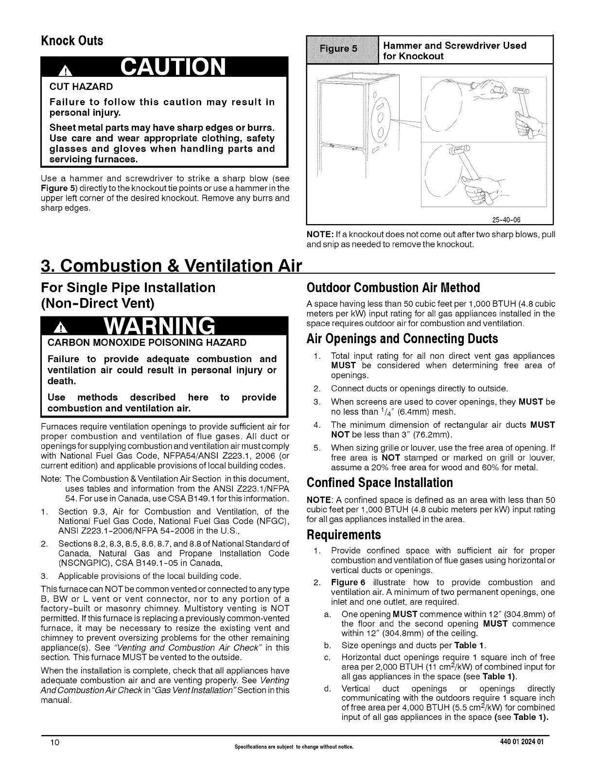
KnockOuts Hammer and Screwdriver Used
for Knockout
CUT HAZARD
Failure to follow this caution may result in
personal injury.
Sheet metal parts may have sharp edges or burrs.
Use care and wear appropriate clothing, safety
glasses and gloves when handling parts and
servicing furnaces.
Use a hammer and screwdriver to strike a sharp blow (see
Figure 5) directly to the knockout tie points or use a hammer inthe
upper left corner of the desired knockout. Remove any burrs and
sharp edges.
25-40-06
NOTE: If a knockout does not come out after two sharp blows, pull
and snip as needed to remove the knockout.
3. Combustion & Ventilation Air
For Single Pipe Installation
(Non-Direct Vent)
CARBON MONOXIDE POISONING HAZARD
Failure to provide adequate combustion and
ventilation air could result in personal injury or
death.
Use methods described here to provide
combustion and ventilation air.
Furnaces require ventilation openings to provide sufficient air for
proper combustion and ventilation of flue gases. All duct or
openings for supplying combustion and ventilation air must comply
with National Fuel Gas Code, NFPA54/ANSI Z223.1, 2006 (or
current edition) and applicable provisions of local building codes.
Note: The Combustion & Ventilation Air Section inthis document,
uses tables and information from the ANSI Z223.1/NFPA
54. For use in Canada, use CSA B149.1 for this information.
1. Section 9.3, Air for Combustion and Ventilation, of the
National Fuel Gas Code, National Fuel Gas Code (NFGC),
ANSI Z223.1-2006/NFPA 54-2006 in the U.S.,
2. Sections 8.2, 8.3, 8.5, 8.6, 8.7, and 8.8 of National Standard of
Canada, Natural Gas and Propane Installation Code
(NSCNGPIC), CSA B149.1-05 in Canada,
3. Applicable provisions of the local building code.
This furnace can NOT be common vented or connected to any type
B, BW or L vent or vent connector, nor to any portion of a
factory-built or masonry chimney. Multistory venting is NOT
permitted. If this furnace is replacing a previously common-vented
furnace, it may be necessary to resize the existing vent and
chimney to prevent oversizing problems for the other remaining
appliance(s). See "Venting and Combustion Air Check" in this
section. This furnace MUST be vented to the outside.
When the installation is complete, check that all appliances have
adequate combustion air and are venting properly. See Venting
And Combustion Air Check in "Gas Vent Installation" Section in this
manual.
OutdoorCombustionAir Method
A space having less than 50 cubic feet per 1,000 BTUH (4.8 cubic
meters per kW) input rating for all gas appliances installed in the
space requires outdoor air for combustion and ventilation.
Air Openingsand Connecting Ducts
1. Total input rating for all non direct vent gas appliances
MUST be considered when determining free area of
openings.
2. Connect ducts or openings directly to outside.
3. When screens are used to cover openings, they MUST be
no less than 1/4" (6.4mm) mesh.
4. The minimum dimension of rectangular air ducts MUST
NOT be less than 3" (76.2mm).
5. When sizing grille or louver, use the free area of opening. If
free area is NOT stamped or marked on grill or louver,
assume a 20% free area for wood and 60% for metal.
Confined SpaceInstallation
NOTE: A confined space is defined as an area with less than 50
cubic feet per 1,000 BTUH (4.8 cubic meters per kW) input rating
for all gas appliances installed in the area.
Requirements
1. Provide confined space with sufficient air for proper
combustion and ventilation of flue gases using horizontal or
vertical ducts or openings.
2. Figure6 illustrate how to provide combustion and
ventilation air. A minimum of two permanent openings, one
inlet and one outlet, are required.
a. One opening MUST commence within 12" (304.8mm) of
the floor and the second opening MUST commence
within 12" (304.8mm) of the ceiling.
b. Size openings and ducts per Table 1.
c. Horizontal duct openings require 1 square inch of free
area per 2,000 BTUH (11 cm2/kW) of combined input for
all gas appliances in the space (see Table 1).
d. Vertical duct openings or openings directly
communicating with the outdoors require 1 square inch
of free area per 4,000 BTUH (5.5 cm2/kW) for combined
input of all gas appliances in the space (see Table 1).
10 Specificationsare subject to changewithout notice. 440 012024 01
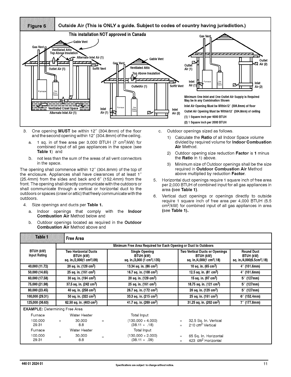
Outside Air (This is ONLY a guide. Subject to codes of country having jurisdiction.)
This installationNOTapprovedinCanada
Alternate InletAir (1)
Ga Ven
/
f
Air (1)
Z
i
_rnacl
.__Gable Vent
fVentilated Attic_
OutletAir(1) Inlet
Air (2)
ou:
Air
SoffitVent
GasVent ........
MinimumOneInlet and One OutletAirSupply is Required
May be in anyCombinationShown
InletAir OpeningMust be Within12" (304.8mm)of floor
OutletAir OpeningMust be Within12" (304.8mm)of ceiling
(1) 1SquareInch per4000 BTUH
(2) 1SquareInch per2000 BTUH
3• One opening MUST be within 12" (304.8mm) of the floor
and the second opening within 12" (304.8mm) of the ceiling•
a. 1 sq. in of free area per 3,000 BTUH (7 cm2/kW) for
combined input of all gas appliances in the space (see
Table 1) and
b. not less than the sum of the areas of all vent connectors
in the space.
The opening shall commence within 12" (304.8mm) of the top of
the enclosure. Appliances shall have clearances of at least 1"
(25.4mm) from the sides and back and 6" (152.4mm) from the
front. The opening shall directly communicate with the outdoors or
shall communicate through a vertical or horizontal duct to the
outdoors or spaces (crawl or attic) that freely communicate with the
outdoors.
4. Size openings and ducts per Table 1.
a. Indoor openings that comply with the Indoor
Combustion Air Method below and
b. Outdoor openings located as required in the Outdoor
Combustion Air Method above and
5•
6•
c• Outdoor openings sized as follows.
1) Calculate the Ratio of all Indoor Space volume
divided by required volume for Indoor Combustion
Air Method.
2) Outdoor opening size reduction Factor is 1 minus
the Ratio in 1) above.
3) Minimum size of Outdoor openings shall be the size
required in Outdoor Combustion Air Method
above multiplied by reduction Factor.
Horizontal duct openings require 1 square inch of free area
per 2,000 BTUH of combined input for all gas appliances in
area (see Table 1).
Vertical duct openings or openings directly to outside
require 1 square inch of free area per 4,000 BTUH (5.5
cm2/kW) for combined input of all gas appliances in area
(see Table 1).
Free Area
MinimumFreeAreaRequiredfor EachOpeningorDucttoOutdoors
BTUH(kW) TwoHorizontalDucts SingleOpening TwoVerticalDuctsorOpenings RoundDuct
InputRating BTUH(kW) BTUH(kW) BTUH(kW) BTUH(kW)
sq.in./2,000(1cm2/.09) sq.in./3,000(1cm2/.135) sq.in./4,000(1cm2/.18) sq.in./4,000(6.5cm2/.18)
40,000(11.72) 20sq.in.(129cm2) 13.34sq.in.(86cm2) 10sq.in.(65cm2) 4" (101.6mm)
50,000(14.65) 25sq.in.(161cm2) 16.7sq.in.(108cm2) 12.5sq.in.(81cm2) 4" (101.6mm)
60,000(17.58) 30sq.in.(194cm2) 20sq.in.(129cm2) 15sq.in.(97cm2) 5" (127mm)
75,000(21.98) 37.5sq.in.(242cm2) 25sq.in.(161cm2) 18.75sq.in.(121cm2) 5" (127mm)
80,000(23.45) 40sq.in.(258cm2) 26.7sq.in.(172cm2) 20sq.in.(129cm2) 5" (127mm)
100,000(29.31) 50sq.in.(322cm2) 33.3sq.in.(215cm2) 25sq.in.(161cm2) 6" (152.4mm)
125,000(36.63) 62.50sq.in.(403cm2) 41.7sq.in.(269cm2) 31.25sq.in.(202cm2) 7" (177.8mm)
EXAMPLE: Determining Free Area
Furnace Water Heater Total Input
100,000 + 30,000 = (130,000 ÷ 4,000) 32.5 Sq. In. Vertical
29.31 8.8 (38.11 ÷ .18) 210 cm2 Vertical
Furnace Water Heater Total Input
100,000 + 30,000 = (130,000 ÷ 2,000) 65 Sq. In. Horizontal
29.31 8.8 (38.11 ÷ .09) 423 cm2 Horizontal
44001202401 Specifications are subject to changewithout notice. 11
IndoorCombustionAir (UnconfinedSpace)
Standard and Known-Air-Infiltration Rate Methods
©NFPA & AGA
Indoor air is permitted for combustion and ventilation, if the
Standard or Known-Air-Infiltration Rate Method is used.
CARBON MONOXIDE POISONING HAZARD
Failure to supply adequate combustion air could
result in personal injury or death.
Most homes will require additional air from
outdoors for combustion and ventilation. A space
with at least 50 cubic feet per 1,000 BTUH (4.8 cubic
meters per kW) input rating or homes with tight
construction may need outdoor air, supplied
through ducts, to supplement air infiltration for
proper combustion and ventilation of flue gases.
The Standard Method may be used, if the space has no less
volume than 50 cubic feet per 1,000 BTUH (4.8 cubic meters per
kW) of the maximum input ratings for atl gas appliances installed in
the space. The standard method permits indoor air to be used for
combustion and ventilation air.
The Known Air Infiltration Rate Method shall be used if the
infiltration rate is known to be less than 0.40 air changes per hour
(ACH) and equal to or greater than 0.10 ACH. Infiltration rates
greater than 0.60 ACH shall not be used. The minimum required
volume of the space varies with the number of ACH and shall be
determined per Table 2 or Equations 1 and 2. Determine the
minimum required volume for each appliance in the space, and
add the volumes together to get the total minimum required
volume for the space.
CARBON MONOXIDE POISONING HAZARD
Failure to supply additional air by means of
ventilation grilles or ducts could result in personal
injury or death.
An unconfined space or homes with tight
construction may not have adequate air infiltration
for proper combustion and ventilation of flue gases.
Most homes will require additional air.
The Known Air Infiltration Rate Method shall be used if the
infiltration rate is known to be less than 0.40 air changes per hour
(ACH) and equal to or greater than 0.10 ACH. Infiltration rates
greater than 0.60 ACH shall not be used. The minimum required
volume of the space varies with the number of ACH and shall be
determined per Table 2 or Equations 1 and 2. Determine the
minimum required volume for each appliance in the space, and
add the volumes together to get the total minimum required
volume for the space.
CARBON MONOXIDE POISONING HAZARD.
Failure to supply additional air by means of
ventilation grilles or ducts could result in personal
injury or death.
An unconfined space or homes with tight
construction may not have adequate air infiltration
for proper combustion and ventilation of flue gases.
Most homes will require additional air.
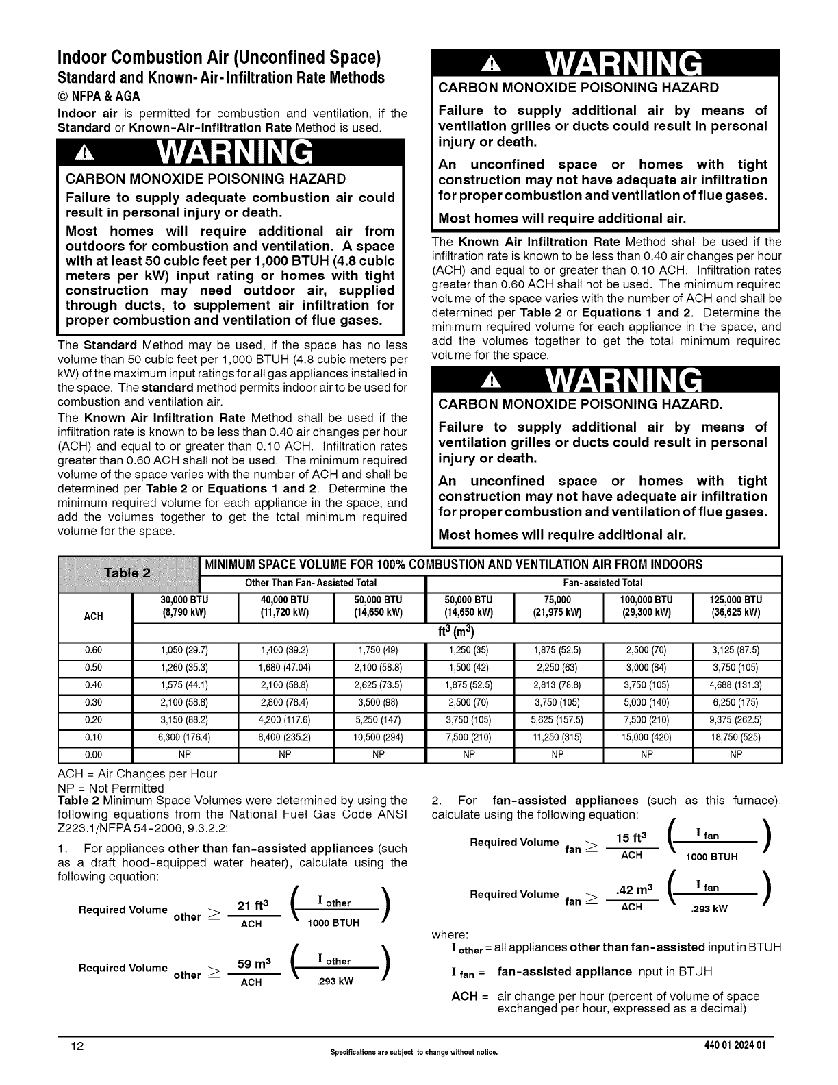
ACH
MINIMUM SPACE VOLUME FOR 100% COMBUSTION AND VENTILATION AIR FROM INDOORS
OtherThanFan-AssistedTotal Fan-assistedTotal
30,000BTU
(8,790kW)
40,000BTU 50,000BTU 75,000 100,000BTU 125,000BTU
(11,720kW) (14,650kW) (21,975kW) (29,300kW) (36,625kW)
0,60 1,050 (29,7) 1,400 (39,2) 1,750 (49) 1,875 (52,5) 2,500 (70) 3,125 (87,5)
0,50 1,260 (35,3) 1,680 (47,04) 2,100 (58,8) 2,250 (63) 3,000 (84) 3,750 (105)
0,40 1,575 (44,1) 2,100 (58,8) 2,625 (73,5) 2,813 (78,8) 3,750 (105) 4,688 (131,3)
0,30 2,100 (58,8) 2,800 (78,4) 3,500 (98) 3,750 (105) 5,000 (140) 6,250 (175)
0,20 3,150 (88,2) 4,200 (117,6) 5,250 (147) 5,625 (157,5) 7,500 (210) 9,375 (262,5)
0,10 6,300 (176,4) 8,400 (235,2) 10,500 (294) 11,250 (315) 15,000 (420) 18,750 (525)
0,00 NP NP NP NP NP NP
50,000BTU
(14,650kW)
ft 3 (m 3)
1,250(35)
1,500(42)
1,875(52,5)
2,500(70)
3,750(105)
7,500(210)
NP
ACH = Air Changes per Hour
NP = Not Permitted
Table 2 Minimum Space Volumes were determined by using the
following equations from the National Fuel Gas Code ANSI
Z223.1/N FPA 54-2006, 9.3.2.2:
1. For appliances other than fan-assisted appliances (such
as a draft hood-equipped water heater), calculate using the
following equation:
-- ACH 1000 BTUH
!\
Required Volume other _59 m3 _|other )
-- ACH .293 kW
2. For fan-assisted appliances (such as this furnace),
calculate using the following equation:
Required Volume fan_ 15ft3 ( .fan )
ACH 1000 BTU H
!\
Required Volume fan _.42 m3 _, [fan )
ACH .293 kW
where:
[other=all appliances other than fan-assisted input in BTUH
[ fan =fan-assisted appliance input in BTUH
ACH = air change per hour (percent of volume of space
exchanged per hour, expressed as a decimal)
12 Specificationsare subject to changewithout notice. 440 012024 01
The following requirements apply to the Standard Method and to
the Known Air Infiltration Rate Method.
• Adjoining rooms can be considered part of a space, if there
are no closable doors between rooms.
• An attic or crawl space may be considered a space that freely
communicates with the outdoors provided there are adequate
ventilation openings directly to outdoors. Openings MUST
remain open and NOT have any means of being closed off.
Ventilation openings to outdoors MUST be at least 1 square
inch of free area per 4,000 BTUH (5.5 cm2/kW) of total input
rating for all gas appliances in the space.
• Combining spaces on the same floor level. Each opening
shall have a free area of at least 1 in2/1,000 BTUH
(22cm2/kW) of the total input rating of all gas appliances in the
space, but not less than 100 in2 (645 cm2). One opening shall
commence within 12" (304.8 mm) of the top and one opening
shall commence within 12" (304.8mm) of the bottom of the
enclosure. The minimum dimension of air openings shall be at
least 3" (76.2 mm).
• Combining spaces on different floor levels. The volumes of
spaces on different floor levels shall be considered
communicating spaces if connected by one or more
permanent openings in doors or floors having a free area of at
least 2 in2/1,000 Btuh (44 cm2/kW) of total input rating of all
gas appliances.
• In spaces that use the Indoor Combustion Air Method,
infiltration should be adequate to provide air for combustion,
ventilation and dilution of flue gases. However, in buildings
with unusually tight construction, additional air MUST be
provided using the methods described in section titled
Outdoor Combustion Air Method:
• Unusually tight construction is defined as Construction with
1. Walls and ceilings exposed to the outdoors have a
continuous, sealed vapor barrier. Openings are
gasketed or sealed and
2. Doors and openable windows are weather stripped and
3. Other openings are caulked or sealed. These include
joints around window and door frames, between sole
plates and floors, between wall-ceiling joints, between
wall panels, at penetrations for plumbing, electrical and
gas lines, etc.
VentilationAir
Some provincial codes and local municipalities require ventilation
or make-up air be brought into the conditioned space as
replacement air. Whichever method is used, the mixed return air
temperature across the heat exchanger MUST not fall below 60°
so that flue gases will not condense excessively in the heat
exchanger. Excessive condensation will shorten the life of the heat
exchanger and possibly void your warranty.
Venting andCombustionAir Check
NOTE: If this installation replaces an existing furnace from a
commonly vented system, the original venting system may no
longer be sized to properly vent the attached appliances. An
improperly sized venting system may cause the formation of
condensate in the vent and the leakage or spillage of vent gases.
To make sure there is adequate combustion air for all appliances,
MAKE THE FOLLOWING CHECK.
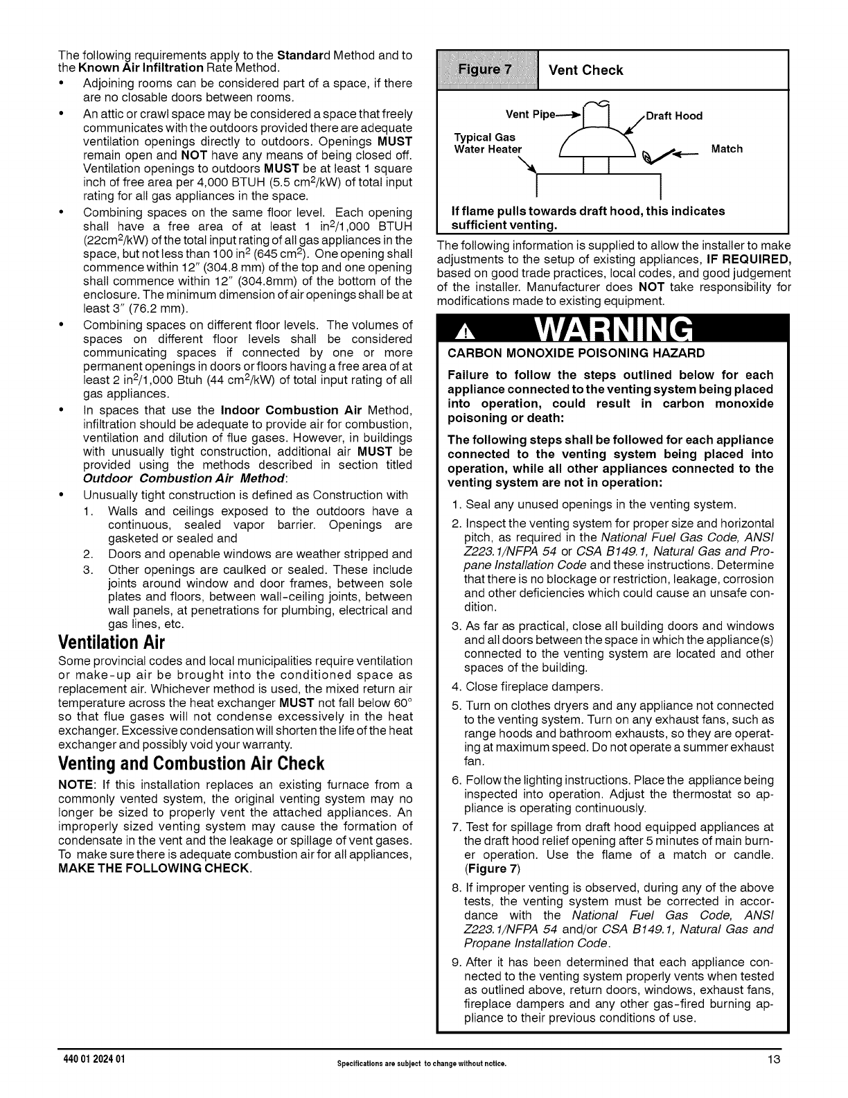
Vent Check
iiiiiiiiiiiiiiiiiiiiiiiiiiiiiiiiiiiiiiiiiiiiiiiiiiiiiiiiiiiiiiiiiiiiiiiiiiiiiiiiiiiiiiiiiiiiiiiiiiiiiiiiiiiiiiiiiiiiiiiiiiiiiiiiiiiiiiiiiiiiiiii
Vent Pipe----_ sDraft Hood
Typical Gas f"_
Water Heater [_ _ j____ Match
I I v
II
If flame pulls towards draft hood, this indicates
sufficient venting.
The following information is supplied to allow the installer to make
adjustments to the setup of existing appliances, IF REQUIRED,
based on good trade practices, local codes, and good judgement
of the installer. Manufacturer does NOT take responsibility for
modifications made to existing equipment.
CARBON MONOXIDE POISONING HAZARD
Failure to follow the steps outlined below for each
appliance connected to the venting system being placed
into operation, could result in carbon monoxide
poisoning or death:
The following steps shall be followed for each appliance
connected to the venting system being placed into
operation, while all other appliances connected to the
venting system are not in operation:
1. Seal any unused openings in the venting system.
2. Inspect the venting system for proper size and horizontal
pitch, as required in the National Fuel Gas Code, ANSI
Z223.1/NFPA 54 or CSA B149.1, Natural Gas and Pro-
pane Installation Code and these instructions. Determine
that there is no blockage or restriction, leakage, corrosion
and other deficiencies which could cause an unsafe con-
dition.
3. As far as practical, close all building doors and windows
and all doors between the space in which the appliance(s)
connected to the venting system are located and other
spaces of the building.
4. Close fireplace dampers.
5. Turn on clothes dryers and any appliance not connected
to the venting system. Turn on any exhaust fans, such as
range hoods and bathroom exhausts, so they are operat-
ing at maximum speed. Do not operate a summer exhaust
fan.
6. Followthe lighting instructions. Place the appliance being
inspected into operation. Adjust the thermostat so ap-
pliance is operating continuously.
7. Test for spillage from draft hood equipped appliances at
the draft hood relief opening after 5 minutes of main burn-
er operation. Use the flame of a match or candle.
(Figure 7)
8. If improper venting is observed, during any of the above
tests, the venting system must be corrected in accor-
dance with the National Fuel Gas Code, ANSI
Z223. 1/NFPA 54 and/or CSA B149.1, Natural Gas and
Propane Installation Code.
9. After it has been determined that each appliance con-
nected to the venting system properly vents when tested
as outlined above, return doors, windows, exhaust fans,
fireplace dampers and any other gas-fired burning ap-
pliance to their previous conditions of use.
440 01 202401 Specificationsare eubject to changewithout notice. 13
For Two Pipe Installation
(DirectVent)
This furnace can NOT be common vented or connected to any type
B, BW or L vent or vent connector, nor to any portion of a
factory-built or masonry chimney. If this furnace is replacing a
previously common-vented furnace, it may be necessary to resize
the existing vent and chimney to prevent oversizing problems for
the other remaining appliance(s). See "Venting and Combustion
Air Check" in this section. This furnace MUST be vented to the
outside.
4. Vent and Combustion Air Piping
CARBON MONOXIDE POISONING HAZARD
Failure to properly vent this furnace could result in
personal injury or death.
Use methods described here to provide combustion
and ventilation air.
Dual Certified(*SMPT,*SMPV,*SMVXModels)
Direct or Non-DirectVent
This furnace is certified as a Category IV furnace. This furnace can
be installed as a direct vent furnace using outside air for
combustion or the furnace can use air from inside the structure for
combustion. The INLET air pipe is optional. If combustion air
comes from inside the structure, adequate make up air MUST be
provided to compensate for oxygen burned. See Confined Space
Installation in the Combustion and Ventilation Air chapter. If
combustion air is drawn from outside the structure, it MUST be
taken from the same atmospheric pressure zone as the vent pipe.
ContaminatedCombustionAir
Installations in certain areas or types of structures will increase the
exposure to chemicals or halogens that may harm the furnace.
The following areas or types of structures may contain or have
exposure to the substances listed below. The installation must be
evaluated carefully as it may be necessary to provide outside air for
combustion.
• Commercial buildings.
• Buildings with indoor pools.
• Furnaces installed in laundry rooms.
• Furnaces installed in hobby or craft rooms.
• Furnaces installed near chemical storage areas.
• Permanent wave solutions for hair.
• Chlorinated waxes and cleaners.
• Chlorine based swimming pool chemicals.
• Water softening chemicals.
• De-icing salts or chemicals.
• Carbon tetrachloride.
• Halogen type refrigerants.
• Cleaning solvents (such as perchloroethylene).
• Printing inks, paint removers, varnishes, etc.
• Hydrochloric acid.
• Sulfuric Acid.
• Solvent cements and glues.
• Antistatic fabric softeners for clothes dryers.
• Masonry acid washing materials.
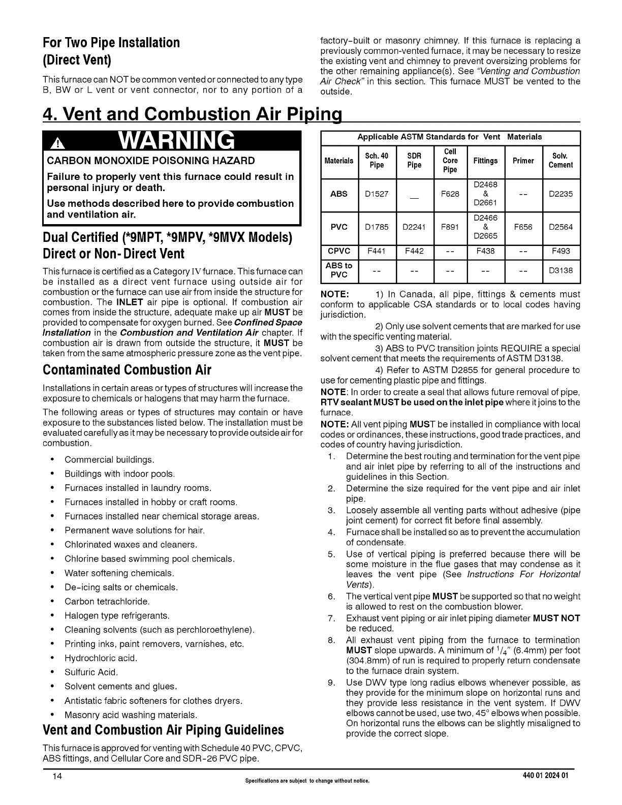
Vent and CombustionAir PipingGuidelines
This furnace is approved for venting with Schedule 40 PVC, CPVC,
ABS fittings, and Cellular Core and SDR-26 PVC pipe.
Applicable ASTM Standardsfor Vent Materials
Cell
Sch.40 SDR Solv.
Materials Pipe Pipe Core Fittings Primer Cement
Pipe
D2468
ABS D1527 F628 & -- D2235
D2661
D2466
PVC D1785 D224t F891 & F656 D2564
D2665
CPVC F44t F442 -- F438 -- F493
ABS to .......... D3138
PVC
NOTE: 1) In Canada, all pipe, fittings & cements must
conform to applicable CSA standards or to local codes having
jurisdiction.
2) Only use solvent cements that are marked for use
with the specific venting material.
3) ABS to PVC transition joints REQUIRE a special
solvent cement that meets the requirements of ASTM D3138.
4) Refer to ASTM D2855 for general procedure to
use for cementing plastic pipe and fittings.
NOTE: In order to create a seal that allows future removal of pipe,
RTV sealant MUST be used on the inlet pipe where itjoins to the
furnace.
NOTE: All vent piping MUST be installed in compliance with local
codes or ordinances, these instructions, good trade practices, and
codes of country having jurisdiction.
1. Determine the best routing and termination for the vent pipe
and air inlet pipe by referring to all of the instructions and
guidelines in this Section.
2. Determine the size required for the vent pipe and air inlet
pipe.
3. Loosely assemble all venting parts without adhesive (pipe
joint cement) for correct fit before final assembly.
4. Furnace shall be installed so as to prevent the accumulation
of condensate.
5. Use of vertical piping is preferred because there will be
some moisture in the flue gases that may condense as it
leaves the vent pipe (See Instructions For Horizontal
Vents).
6. The vertical vent pipe MUST be supported so that no weight
is allowed to rest on the combustion blower.
7. Exhaust vent piping or air inlet piping diameter MUST NOT
be reduced.
8. All exhaust vent piping from the furnace to termination
MUST slope upwards. A minimum of 1/4" (6.4mm) per foot
(304.8mm) of run is required to properly return condensate
to the furnace drain system.
9. Use DWV type long radius elbows whenever possible, as
they provide for the minimum slope on horizontal runs and
they provide less resistance in the vent system. If DWV
elbows cannot be used, use two, 45 ° elbows when possible.
On horizontal runs the elbows can be slightly misatigned to
provide the correct slope.
14 Specificationsare subject to changewithout notice. 440 012024 01
10. All horizontal pipe runs MUST be supported at least
every five feet with galvanized strap or other rust
resistant material. NO sags or dips are permitted.
11. All vertical pipe runs MUST be supported every six feet
where accessible.
12. The maximum pipe length is 40' (12.2m) total in the inlet or
outlet side of the system. Up to five, 90 ° elbows can be used
on the inlet or the outlet. With the Concentric Vent
Termination Kits (NAHA001CV or NAHA002CV), the
maximum pipe length is 35' (10.7m) with four 90 ° elbows. If
more elbows are required, reduce the length of both the inlet
and exhaust pipes 5' (1.5m) for each additional elbow used.
(See Table 3 or Table 4).
13. The minimum vent length is 5' (1.5m) of PVC.
14. The piping can be run in the same chase or adjacent to
supply or vent pipe for water supply or waste plumbing. It
can also be run in the same chase with a vent from another
90+ furnace.
NOTE: In NO case can the piping be run in a chase where
temperatures can exceed 140 ° F (60 ° C). or where radiated
heat from adjacent surfaces would exceed 140° F(60 ° C).
15. The vent outlet MUST be installed to terminate in the same
atmospheric pressure zone as the combustion air inlet.
16. The vent system can be installed in an existing unused
chimney provided that:
• Both the exhaust vent and air intake run the length of the
chimney.
• No other gas fired appliance or fireplace (solid fuel) is
vented into the chimney.
• The top of the chimney MUST be sealed flush or crowned
up to seal against rain or melting snow so ONLYthe piping
protrudes.
• The termination clearances shown in Figure8 are
maintained.
17. Furnace applications with vertical vents requiring vent
diameter increaser fittings must have increaser fittings
installed in vertical portion of the vent. Condensate will be
trapped in the vent if the vent diameter is increased prior to
having an elbow turned upward. This could cause nuisance
tripping of the pressure switch.
CombustionAir andVent PipingInsulation
Guidelines
NOTE: Use closed cell, neoprene insulation or equivalent. If
Fiberglass or equivalent insulation is used it must have a vapor
barrier. Use R values of 7 up to 10' (3.1m), R-11 if exposure
exceeds 10' (3.1 m). If Fiberglass insulation is used, exterior to the
structure, the pipe MUST be boxed in and sealed against moisture.
1. When the vent or combustion air pipe height above the roof
exceeds 30" (76.2mm), or if an exterior vertical riser is used
on a horizontal vent to get above snow levels, the exterior
portion MUST be insulated.
2. When combustion air inlet piping is installed above a
suspended ceiling, the pipe MUST be insulated with
moisture resistant insulation such as Armaflex or other
equivalent type of insulation.
3. Insulate combustion air inlet piping when run in warm,
humid spaces.
SizingCombustionAir andVent Pipe
Consult Table 3 or Table 4 to select the proper diameter exhaust
and combustion air piping. Exhaust and combustion air piping is
sized for each furnace Btuh size based on total lineal vent length
(on inlet or outlet side), and number of 90 ° elbows required.
1. Double Pipe Installation-If installing as a direct-vent
appliance, consult Table 4 to select the proper diameter
exhaust and combustion air piping. Exhaust and
combustion air piping is sized for each furnace Btuh size
based on total lineal vent length (on inlet or outlet side), and
number of 90° elbows required.
2. Single Pipe Installation-If installing as a non-direct vent
appliance, (single outlet pipe and no inlet pipe) refer to
Table 3. The table shows the maximum number of elbows
allowed with any given pipe diameter and length of run.
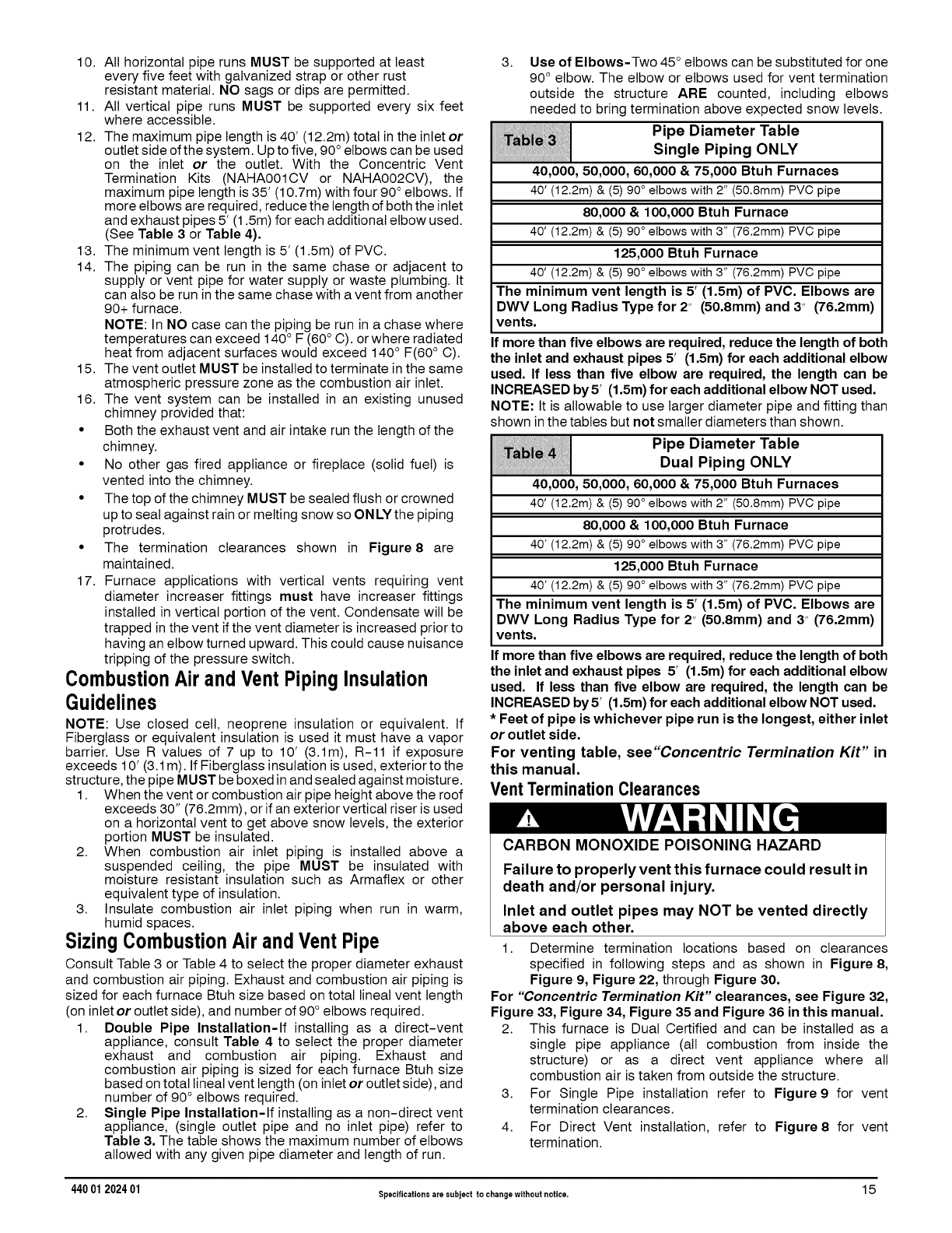
3. Use of Elbows-Two 45° elbows can be substituted for one
90° elbow. The elbow or elbows used for vent termination
outside the structure ARE counted, including elbows
needed to bring termination above expected snow levels.
Pipe Diameter Table
Single Piping ONLY
40,000, 50,000, 60,000 & 75,000 Btuh Furnaces
40' (12.2m) & (5) 90° elbows with 2" (50.8mm) PVC pipe
80,000 & 100,000 Btuh Furnace
40' (12.2m) & (5) 90° elbows with 3" (76.2mm) PVC pipe
125,000 Btuh Furnace
40' (12.2m) & (5) 90° elbows with 3" (76.2mm) PVC pipe
The minimum vent length is 5' (1.5m) of PVC. Elbows are
DWV Long Radius Type for 2" (50.Smm) and 3" (76.2mm)
vents.
If more than five elbows are required, reduce the length of both
the inlet and exhaust pipes 5' (1.5m) for each additional elbow
used. If less than five elbow are required, the length can be
INCREASED by 5' (1.5m) for each additional elbow NOT used.
NOTE: It is allowable to use larger diameter pipe and fitting than
shown in the tables but not smaller diameters than shown.
Pipe Diameter Table
Dual Piping ONLY
40,000, 50,000, 60,000 & 75,000 Btuh Furnaces
40' (12.2m) & (5) 90° elbows with 2" (50.8mm) PVC pipe
80,000 & 100,000 Btuh Furnace
40' (12.2m) & (5) 90° elbows with 3" (76.2mm) PVC pipe
125,000 Btuh Furnace
40' (12.2m) & (5) 90° elbows with 3" (76.2mm) PVC pipe
The minimum vent length is 5' (1.5m) of PVC. Elbows are
DWV Long Radius Type for 2" (50.Smm) and 3" (76.2mm)
vents.
If more than five elbows are required, reduce the length of both
the inlet and exhaust pipes 5' (1.5m) for each additional elbow
used. If less than five elbow are required, the length can be
INCREASED by 5' (1.5m) for each additional elbow NOT used.
*Feet of pipe is whichever pipe run is the longest, either inlet
or outlet side.
For venting table, see"Concentric Termination Kit" in
this manual.
Vent Termination Clearances
CARBON MONOXIDE POISONING HAZARD
Failure to properly vent this furnace could result in
death and/or personal injury.
Inlet and outlet pipes may NOT be vented directly
above each other.
1. Determine termination locations based on clearances
specified in following steps and as shown in Figure 8,
Figure 9, Figure 22, through Figure 30.
For "Concentric Termination Kit" clearances, see Figure 32,
Figure 33, Figure 34, Figure 35 and Figure 36 in this manual.
2. This furnace is Dual Certified and can be installed as a
single pipe appliance (all combustion from inside the
structure) or as a direct vent appliance where all
combustion air is taken from outside the structure.
3. For Single Pipe installation refer to Figure 9 for vent
termination clearances.
4. For Direct Vent installation, refer to Figure 8 for vent
termination.
440 01 202401 Specificationsare subject to changewithout notice. 1 5
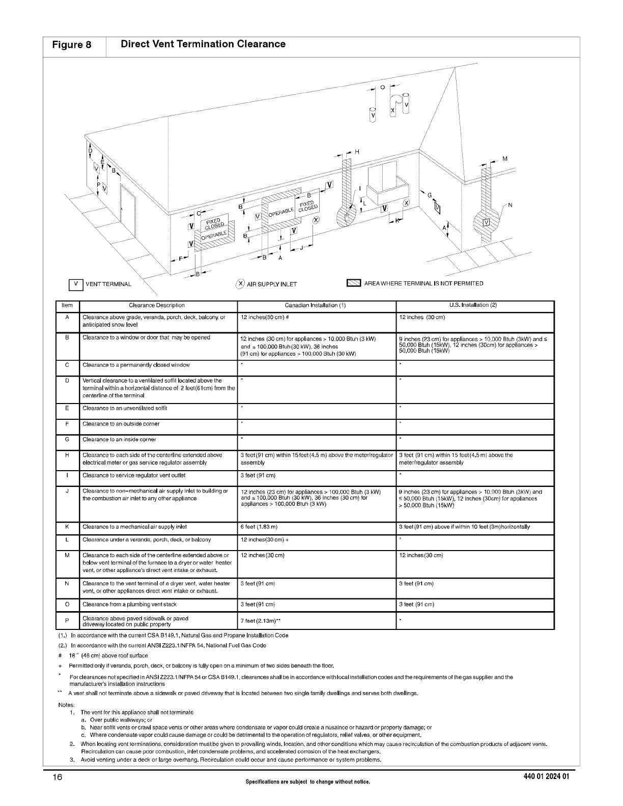
Figure 8 Direct Vent Termination Clearance
D VENTTERMINAL
\\\\x
_X_ AIR SUPPLY INLET E_ AREA WHERE TERMINAL IS NOT PERMITED
Item Clearance Description Canadian Inslallafion (1) U.S. Installation (2)
A Clearance above grade, veranda, porch, deck, balcony, or 12 inches(30 cm) # 12 inches (30 cm)
anticipated snow level
B Clearance to a window or door that may be opened 12 inches (30 cm) for appliances > 10,000 Btuh (3 kW) 9 inches (23 era) for appliances > 1O,0O0 Btuh (3kW) and s
and s 100,000 Btuh(30 kW), 36 inches 50,000 Btuh 15kW), 12 inches (30cm) for appliances >
(91 cm) for appliances > 100,000 Btuh (30 kW) 50,000 Btuh (ISkW
C Clearance to a permanently closed window
D Vertical clearance to a ventilated soffit located above [he
terminal within a horizontal distance of 2 feet(61em) from the
centerline of the terminal
E Clearance to an unventilated soffit
F Clearance to an OL_side corner
G Clearance to an inside corner
H Clearance to each side of the centerline extended above 3 feet (91 cm) within 15 feet (4.5 m) above the meter/regulator 3 feet (9t cm) within 15 feet(4.5 m) above the
electrical meter or gas service regulator assembly assembly meter/regulator assembly
I Clearance to service regulator vent outlet 3 feet (91 cm)
J Clearance to non-mechanical air supply inlet to building or 12 inches (23 era) for appliances > 100,000 Btuh (3 kW) 9 inches (23 cm) for appliances > 10,000 Btuh (3kW) and
the combustion air inlet to any other appliance and s 100,000 Btuh (30 kW), 36 inches (30 cm) for _ 50,000 Btuh (15kW), 12 inches (30cm) for appliances
appliances > 100,000 Btuh (3 kW) > 50,000 Btuh (15kW)
K Clearance to a mechanical air supply inlet 6 feet (1.83 m) 3 feet (91 cm) above if within 10 feet (3re)horizontally
L Clearance under a veranda, porch, deck, or balcony 12 inches(30 cm) +
M Clearance to each side of the centerline extended above or 12 inches (30 em) 12 inches (30 cm)
below vent terminal of the furnace to a dryer or water heater
vent, or other appliance's direct vent inlake or exhaust.
N Clearance to the vent terminal of a dryer vent, water heater 3 feet (91 cm) 3 feet (91 cm)
vent, or other appliances direct vent intake or exhaust.
Q Clearance from a plumbing vent stack 3 feet (91 cm) 3 feet (91 cm)
p Clearance above paved sidewalk or paved 7 feet (2.t 3m)**
driveway located on public property
(1.) In accordance with the current CSA B149.1, Natural Gas and Propane Installation Code
(2.) In accordance with the cu trent ANSI Z223.1/NFPA 54, National Fuel Gas Code
# 18" (46 cm) above roof surface
+ Perrnitted only if veranda, porch, deck, or balcony is fully open on a mthimum of two sides beneath the floor.
For clearances not specified in ANSI Z223.1/NFPA 54 or CSA B t49.1, clearances shall be in accordance with local inetallation codes and the requirements of the gas supplier and the
manufacturer's installation instructions
A vent shall not terminate above a sidewalk or paved driveway that is located between two single family dwellings and serves both dwellings.
Notes:
1,
2.
3.
16
The vent for this appliance shall not terminate
a. Over public walkways; or
b. Near soffit vents or crawl space vents or other areas where condensate or vapor could create a nusalnee or hazard or property damage; or
e. Where condensate vapor could cause damage or could be detrimental to the operation of regulators, relief valves, or other equipment.
When locating vent terminations, consideration must be given to prevailing winds, location, and other conditionswhich may cause recirculation of the combustion products of adjacent vents.
Recirculation can cause poor combustion, inlet condensate problems, and accelerated corrosion of the heat exchangers.
Avoid venting under a deck or large overhang. Recirculation could occur and cause performance or system problems.
440 012024 01
Specifications are eubject to change without notice.
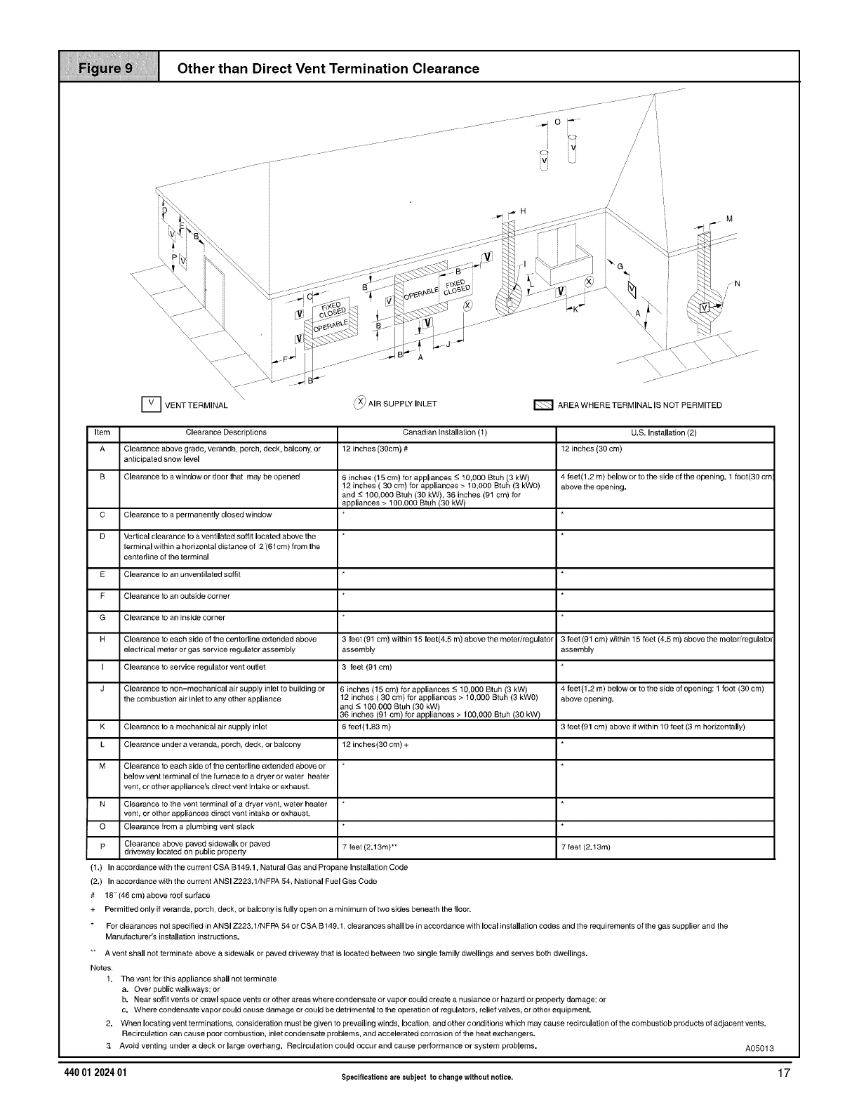
Other than Direct Vent Termination Clearance
D VENT TERMINAL \_ _X_ AIR SUPPLY INLET E_ AREA WHERE TERMINAL IS NOT PERMITED
Item Clearance Descriptions
A Clearance above grade, veranda, porch, deck, balcony, or
anticipated snow level
B Clearance to a window or door that may be opened
K
L
M
C Clearance to a permanently closed window
D Vertical clearance to a ventilated soffit located above the
terminal within a horizontal distance of 2"(61cm) from the
centerline of the terminal
E Clearance to an unventilated soffit
F Clearance to an outside corner
G Clearance to an inside corner
H Clearance to each side of the centerline extended above
electrical meter or gas service regulator assembly
I Clearance to service regulator vent outlet
J Clearance to non-mechanical air supply inlet to building or
the combustion air inlet to any other appliance
Clearance to a mechanical air supply inlet
Clearance under a veranda, porch, deck, or balcony
Canadian Installation (t)
12 inches (30cm) #
6 inches (15 cm) for appliances -< 10,000 Btuh (3 kW)
12 inches ( 30 cm) for appliances > 10,000 Btuh (3 kW0)
and -< 100,000 Btuh (30 kW), 36 inches (91 cm) for
appliances > 100,000 Btuh (30 kW)
3 feet (91 cm) within 15 feet(4.5 m) above the meter/regulator
assembly
3 feet (91 cm)
6 inches (15 cm) for appliances -< 10,000 Btuh (3 kW)
12 inches ( 30 cm) for appliances > 10,000 Btuh (3 kW0)
and -< 100,000 Btuh (30 kW)
36 inches (91 cm) for appliances > 100,000 Btuh (30 kW)
6 feet(1.83 m)
12 inches(30 am) +
Clearance to each side of the centerline extended above or
below vent terminal of the furnace to a dryer or water heater
vent, or other appliance's direct vent intake or exhaust.
N Clearance to the vent terminal of a dryer vent, water heater
vent, or ether appliances direct vent intake or exhaust.
O Clearance from a plumbing vent stack
p Clearance above paved sidewalk or paved 7 feel (2.13m)**
driveway located on public property
(1.) In accordance with the current CSA B149.1, Natural Gas and Propane Installation Code
(2.) In accordance with the currant ANSI Z223.1/NFPA 54, National Fuel Gas Code
# 18'(46cm) above roof surface
U.S. Installation (2)
12 inches (30 cm)
4 feet(1.2 m) below or to the side of the opening. 1 foot(30 cm
above the opening.
3 feet (91 cm) Within 15 feet (4.5 m) above the meter/regulatol
assembly
4 feet(1.2 m) below or to the side of opening: 1 foot (30 cm)
above opening.
3 feet(91 cm) above if within 10 feet (3 m horizontally)
7 feet (2.13m)
+ Permitted only if veranda, porch, deck, or balcony is fully open on a minimum of two sides beneath the floor.
For clearances not specified in ANSI Z223.1/NFPA 54 or CSA B149.1, clearances shall be in accordance with local installationcodes and Ihe requirements of the gas supplier and the
Manufacturer's installation instructions.
** A vent shall not terminate above a sidewalk or paved driveway that is located between two single family dwellings and serves both dwellings.
Notes:
1. The vent for this appliance shall not terminate
a. Over publicwalkweys; or
b. Nears__itvents_rcraw_spacevents_r_therareaswherec_ndensate_rvap_rc_u_dcreateanusiance_rhazard_rpr_pertydamage;_r
c. Wherec_ndensatevap_rc_u_d_ausedamage_r_dbedetrimenta_t_t_e_perati_n_fregu_a_rs_re_iefva_ves_r_therequipment_
2. When locating vent terminations, consideration must be given to prevailing winds, location, and other c onditions which may cause recirculation of the cembustiob products of adjacent vents.
Recirculation can cause poor combustion, inlet condensate problems, and accelerated corrosion of the heat exchangers.
3 Avoid venting under adeck or large overhang. Recirculation could occur end cause performance or system problems. A05013
440 01 202401 Specificationsare eubject to changewithout notice. 1 7
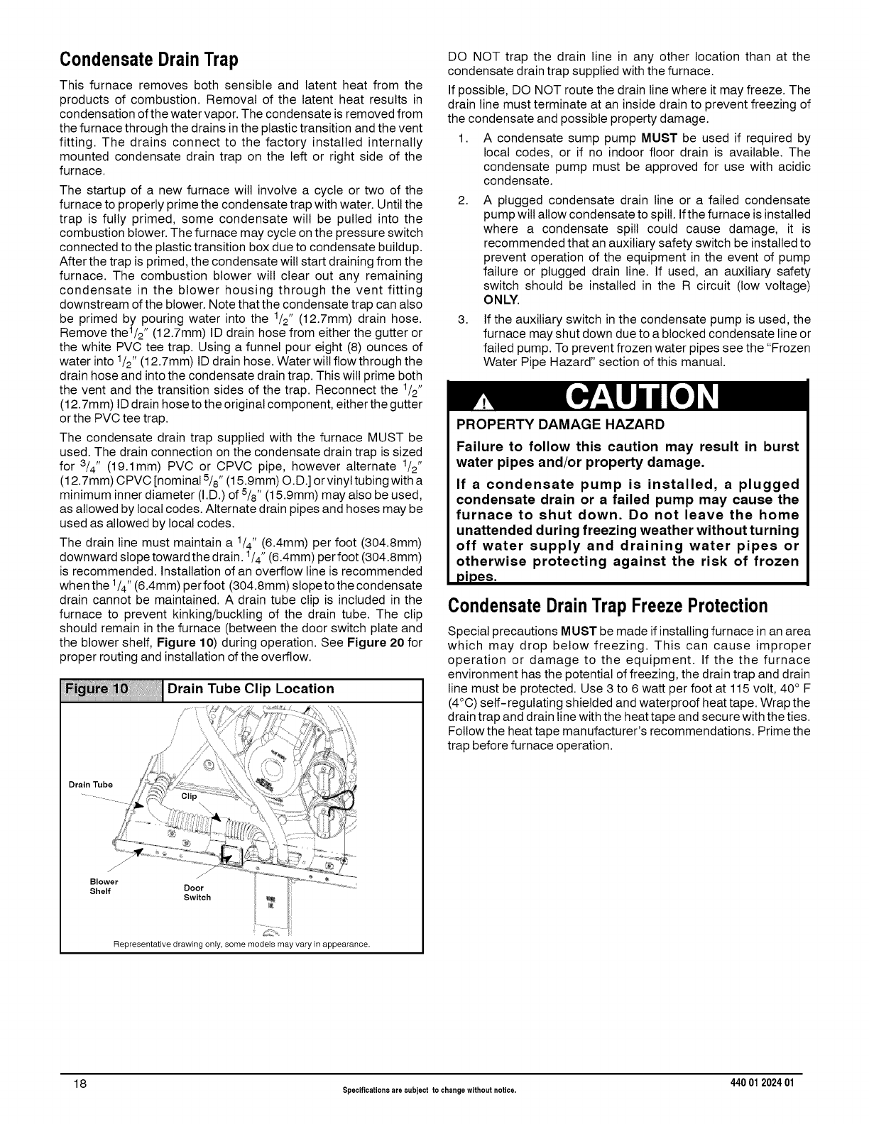
CondensateDrainTrap
This furnace removes both sensible and latent heat from the
products of combustion. Removal of the latent heat results in
condensation of the water vapor. The condensate is removed from
the furnace through the drains in the plastic transition and the vent
fitting. The drains connect to the factory installed internally
mounted condensate drain trap on the left or right side of the
furnace.
The startup of a new furnace will involve a cycle or two of the
furnace to properly prime the condensate trap with water. Until the
trap is fully primed, some condensate will be pulled into the
combustion blower. The furnace may cycle on the pressure switch
connected to the plastic transition box due to condensate buildup.
After the trap is primed, the condensate will start draining from the
furnace. The combustion blower will clear out any remaining
condensate in the blower housing through the vent fitting
downstream of the blower. Note that the condensate trap can also
be primed by pouring water into the 1/2" (12.7mm) drain hose.
Remove the1/2 '' (12.7mm) ID drain hose from either the gutter or
the white PVC tee trap. Using a funnel pour eight (8) ounces of
water into 1/2" (12.7mm) ID drain hose. Water will flow through the
drain hose and into the condensate drain trap. This will prime both
the vent and the transition sides of the trap. Reconnect the 1/2"
(12.7mm) ID drain hose to the original component, either the gutter
or the PVC tee trap.
The condensate drain trap supplied with the furnace MUST be
used. The drain connection on the condensate drain trap is sized
for 3/4" (19.1mm) PVC or CPVC pipe, however alternate 1/2"
(12.7mm) CPVC [nominal 5/8" (15.gmm) O. D.] or vinyl tubing with a
minimum inner diameter (I.D.) of 5/8" (15.gmm) may also be used,
as allowed by local codes. Alternate drain pipes and hoses may be
used as allowed by local codes.
The drain line must maintain a 1/4" (6.4mm) per foot (304.8mm)
downward slope toward the drain. 1/4" (6.4mm) per foot (304.8mm)
is recommended. Installation of an overflow line is recommended
when the 1/4"(6.4mm) per foot (304.8mm) slope to the condensate
drain cannot be maintained. A drain tube clip is included in the
furnace to prevent kinking/buckling of the drain tube. The clip
should remain in the furnace (between the door switch plate and
the blower shelf, Figure 10) during operation. See Figure 20 for
proper routing and installation of the overflow.
Fi_ _ !'i'111Drain Tube Clip Location
iiiiiiiiiiiiiiiiiiiiiiiiiiiiiiiiiiiiiiiiiiiiiiiiiiiiiiiiiiiiiiiiii
Drain Tube
f
Blower
Shelf Door
Switch
Representative drawing only, some models may vary in appearance.
DO NOT trap the drain line in any other location than at the
condensate drain trap supplied with the furnace.
If possible, DO NOT route the drain line where it may freeze. The
drain line must terminate at an inside drain to prevent freezing of
the condensate and possible property damage.
1. A condensate sump pump MUST be used if required by
local codes, or if no indoor floor drain is available. The
condensate pump must be approved for use with acidic
condensate.
2. A plugged condensate drain line or a failed condensate
pump will allow condensate to spill. Ifthe furnace is installed
where a condensate spill could cause damage, it is
recommended that an auxiliary safety switch be installed to
prevent operation of the equipment in the event of pump
failure or plugged drain line. If used, an auxiliary safety
switch should be installed in the R circuit (low voltage)
ONLY.
3. If the auxiliary switch in the condensate pump is used, the
furnace may shut down due to a blocked condensate line or
failed pump. To prevent frozen water pipes see the "Frozen
Water Pipe Hazard" section of this manual.
PROPERTY DAMAGE HAZARD
Failure to follow this caution may result in burst
water pipes and/or property damage.
If a condensate pump is installed, a plugged
condensate drain or a failed pump may cause the
furnace to shut down. Do not leave the home
unattended during freezing weather without turning
off water supply and draining water pipes or
otherwise protecting against the risk of frozen
pipes.
CondensateDrainTrap Freeze Protection
Special precautions MUST be made if installing furnace in an area
which may drop below freezing. This can cause improper
operation or damage to the equipment. If the the furnace
environment has the potential of freezing, the drain trap and drain
line must be protected. Use 3 to 6 watt per foot at 115 volt, 40 ° F
(4°0) self-regulating shielded and waterproof heat tape. Wrap the
drain trap and drain line with the heat tape and secure with the ties.
Follow the heat tape manufacturer's recommendations. Prime the
trap before furnace operation.
18 Specifications are eubject to changewithout notice. 440 012024 01

iiiiiii!iiiiiii!iiii iup,,ow,noto,,ot,onoTopVent
iiiiiiiiiiiiiiiiiiiiiiiiiiiiiiiiiiiiiiiiiiiiiiiiiiiiiiiiiiiiiiiiiiiiiiiiiiiiiiiiiiiiiiiiiiiiiiiiiiiiiiiiiiiiiiiiiiiiiiiiiiiiiiiiiiiiiiiiiiiiiiii
Vent Drain
& Clamps
Dual Pressure Switch Detail
,,*,i
F_\ J
wOn SomeModels
zJ jZ ONLY
Plastic Caps (2)
Yellow or black _. _ ....................................
Coupling&Clamps ...................
(Optional) ................................._ ......................................................./ /
Single Pressure Switch
ReliefTube
z ........BlackRubber3/16"
(4.8mm)ID
_StreetElbow
1/2" (12.7mm)CPVC
(Loosepartsbag)
(12.7mm)CPVC(Loose
partsbag)'_ ...... /....... _ _" _/o] _"
/
CasingGrommet ',, _(7_h _ ..... • _i _/=_;J_
BlackRubber-_ "' \ /..... _ _ I_'_; _,_ ;.b
5/8"( S.mmm) D ',,
<Loosepartsbag, - _ __ ..... _ .... __ "_'_
DrainLineVentTee3/4" DrainTubeBlackRubber5/8"(15.9mm)ID &
(18.1mm)PVCor1/2"(12.7mm)
CPVC(Fieldsupplied) Clamps,Cutlengthtofit (Loosepartsbag)
Representative drawing only, some models may vary in appearance,
Upflow Installations Top Vent (SeeFigure11)
Remove knockout from the side of the furnace casing where drain
tube will exit.
Install casing grommet [black rubber 5/8" (15.9mm) ID grommet -
in loose parts bag].
Install the 1/2" (12.7mm) CPVC street elbow on discharge of trap
Install the black PVC tube connector [ 3/4" (18.1mm) PVC x _/2"
(12.7mm) CPVC from loose parts bag] as shown in the illustration
above.
Cut the black drain tube [5/8" (15.9mm) ID - in loose parts bag] to
length to fit between trap and tube connector through grommet.
Clamp both ends of the drain tube using clamps provided.
25-24-67
Glue the CPVC street elbow to the trap using appropriate cleaner
and solvent cement.
The field supplied 3/4" (18.1mm) PVC or 1/2" (12.7mm) CPVC
drain line vent tee must vent outside the furnace cabinet (see
exploded view above),
Note: It is recommended that all PVC piping and fitting
connections be fit up and inspected before final cementing. Trap
must be primed before operation, Verify all condensate drain
connections are securely clamped. A coupling and clamps (in
loose part bag) may be installed as shown for future servicing of
the vent system.
NOTE:"PVC"is used as a generic term. Pipe and fi_ingmaterials used must be acceptable to the local code officials having
jurisdiction.
440 01 202401 Specificationsare subject to changewithout notice. 1 9
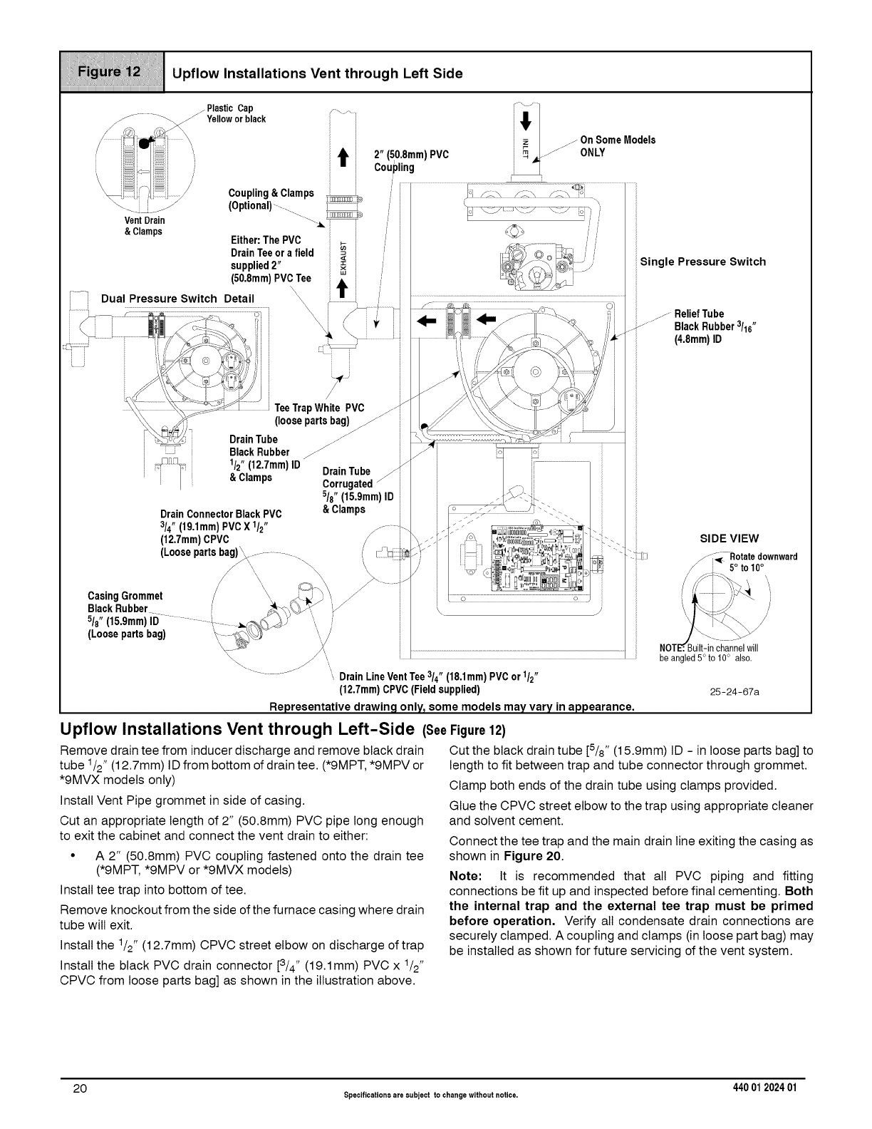
iiiiii;_iiiiii;iii!iii1iiiiiii_i!iii1iiii;;1i_ii1i!!!iiiiiii1i1ii_iI!!!!iiiiii_iiiiiiiiiHi1iii;iiiiiiiii;iiiIiiiiYi1iiii!!ii1iiiii
Upflow Installations Vent through Left Side
iiiiiiiiiiiiiiiiiiiiiiiiiiiiiiiiiiiiiiiiiiiiiiiiiiiiiiiiiiiiiiiiiiiiiiiiiiiiiiiiiiiiiiiiiiiiiiiiiiiiiiiiiiiiiiiiiiiiiiiiiiiiiiiiiiiiiiiiiiiiiiii
25-24-67a
Representative drawing only_ some models may vary in appearance,
Upflow Installations Vent through Left-Side (See
Remove drain tee from inducer discharge and remove black drain
tube 1/2" (12.7mm) ID from bottom of drain tee. (*9MPT, *9MPV or
*9MVX models only)
Install Vent Pipe grommet in side of casing.
Cut an appropriate length of 2" (50.8mm) PVC pipe long enough
to exit the cabinet and connect the vent drain to either:
• A 2" (50.8mm) PVC coupling fastened onto the drain tee
(*9MPT, *9MPV or *9MVX models)
Install tee trap into bottom of tee.
Remove knockout from the side of the furnace casing where drain
tube will exit.
Install the 1/2" (12.7mm) CPVC street elbow on discharge of trap
Install the black PVC drain connector [3/4" (19.1mm) PVC x 1/2"
CPVC from loose parts bag] as shown in the illustration above.
Figure 12)
Cut the black drain tube [5/8" (15.9mm) ID - in loose parts bag] to
length to fit between trap and tube connector through grommet.
Clamp both ends of the drain tube using clamps provided.
Glue the CPVC street elbow to the trap using appropriate cleaner
and solvent cement.
Connect the tee trap and the main drain line exiting the casing as
shown in Figure 20.
Note: It is recommended that all PVC piping and fitting
connections be fit up and inspected before final cementing. Both
the internal trap and the external tee trap must be primed
before operation. Verify all condensate drain connections are
securely clamped. A coupling and clamps (in loose part bag) may
be installed as shown for future servicing of the vent system.
20 Specificationsare eubject to changewithout notice. 440 012024 01
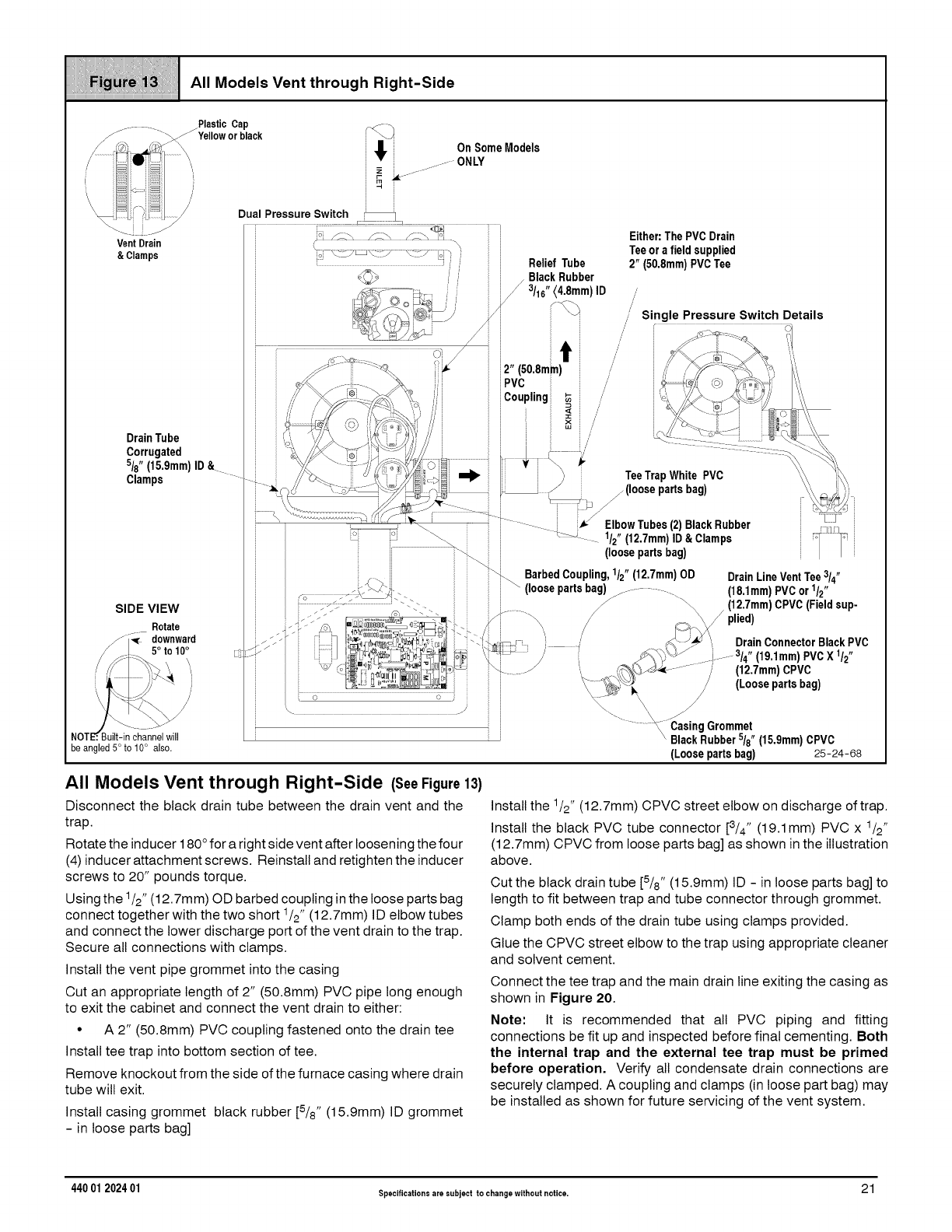
_i_;ii_i_i_i_i_i_i!i_i_!_i_i_1_i_
be angled 5° to 10° also. (Loose partsbag) 25-24-68
All Models Vent through Right-Side (SeeFigure13)
Disconnect the black drain tube between the drain vent and the
trap.
Rotate the inducer 180 °for a right side vent after loosening the four
(4) inducer attachment screws. Reinstall and retighten the inducer
screws to 20" pounds torque.
Using the 1/2"(12.7mm) OD barbed coupling in the loose parts bag
connect together with the two short 1/2" (12.7mm) ID elbow tubes
and connect the lower discharge port of the vent drain to the trap.
Secure all connections with clamps.
Install the vent pipe grommet into the casing
Cut an appropriate length of 2" (50.8mm) PVC pipe long enough
to exit the cabinet and connect the vent drain to either:
• A 2" (50.8mm) PVC coupling fastened onto the drain tee
Install tee trap into bottom section of tee.
Remove knockout from the side of the furnace casing where drain
tube will exit.
Install casing grommet black rubber [5/8" (15.9mm) ID grommet
- in loose parts bag]
Install the 1/2" (12.7mm) CPVC street elbow on discharge of trap.
Install the black PVC tube connector [3/4" (19.1mm) PVC x 1/2"
(12.7mm) CPVC from loose parts bag] as shown in the illustration
above.
Cut the black drain tube [5/8" (15.9mm) ID - in loose parts bag] to
length to fit between trap and tube connector through grommet.
Clamp both ends of the drain tube using clamps provided.
Glue the CPVC street elbow to the trap using appropriate cleaner
and solvent cement.
Connect the tee trap and the main drain line exiting the casing as
shown in Figure 20.
Note: It is recommended that all PVC piping and fitting
connections be fit up and inspected before final cementing. Both
the internal trap and the external tee trap must be primed
before operation. Verify all condensate drain connections are
securely clamped. A coupling and clamps (in loose part bag) may
be installed as shown for future servicing of the vent system.
440 01 202401 Specificationsare subject to changewithout notice. 21
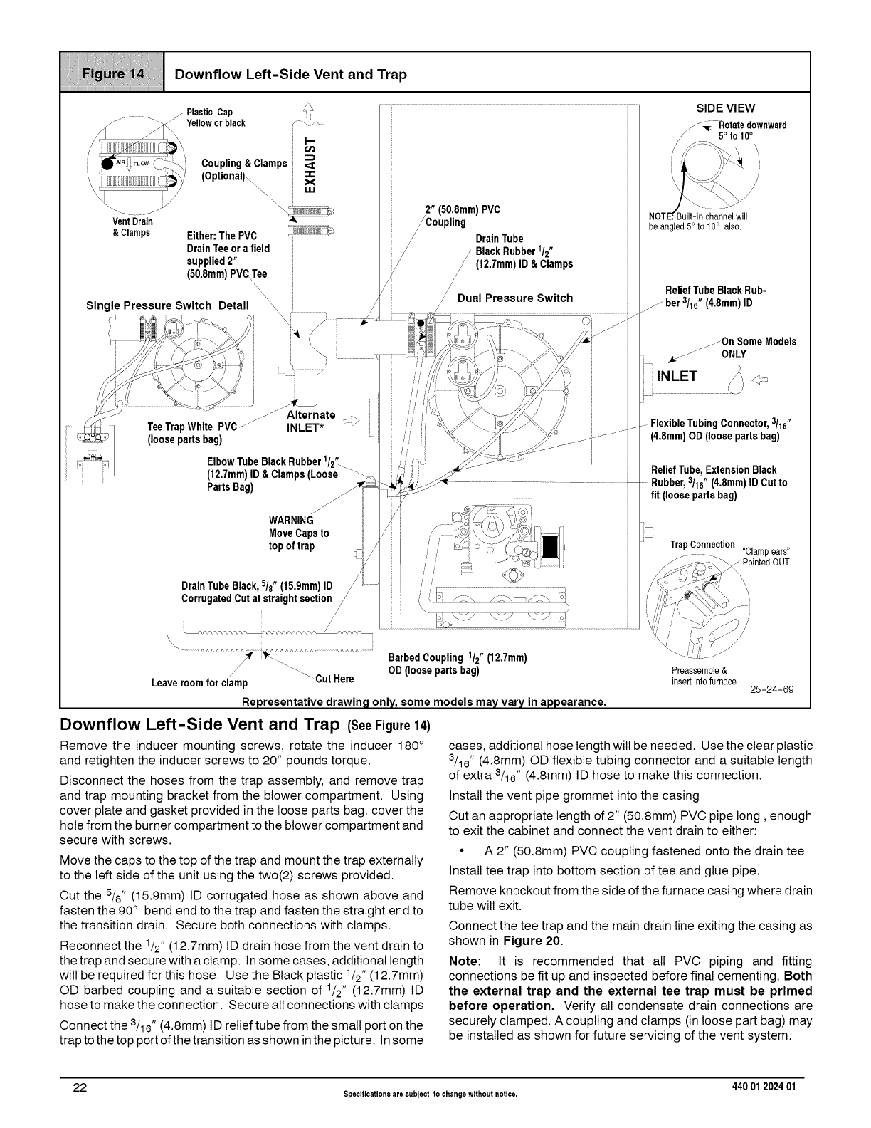
_i_7i_i_i_i7_;_7i_@_
iiiiiiiiiiiiiiiiiiiiiiiiiiiiiiiiiiiiiiiiiiiiiiiiiiiiiiiiiiiiiiiiiiiiiiii
/Plastic Cap SIDE VIEW
/_:_r_Rotate downward
// 5° to 10°
/--/Coupling NOT channel will
be angled 5° to t0° also,
/-- DrainTube
/,BlackRubber1/2"
// (12.7mm)ID&Clamps _
/
/ReliefTubeBlackRub-
\ _ i _ / Dual Pressure Switch _ zber 3/16" (48mm) lD
Single Pressure Switch Detail _ i /_./ •
,////,7' /_/-_'17', _ ;/ ;;/>/"_-- !',,m _. _.// ..- ONLY
_;'S__<_ _ '_ ............'<J' <<_................." /\\ ': - < ....
//_,k/_\i_"_, k_%._jS,' i,' II _r'_:'// 7;o06/_'-.('_ i/J"-.-"
' j_) _,\_.,_ /_ i ; //J'<_ ' ' I, i
///73;) ..... Alternate .-.. i ii 'i <\, _=;</_'/_ ,<;;) i i
_/_ TeeTrapWhitePVC.......... INLET* :h i i ii ii _. 1o_//_ X')' i _--FlexibleTubingConnector,'/16"
c_i_ (loosepartsbag) ' i;'/ /';i _>./___._/___- ..................i i (4.8mm)OD(loosepartsbag)
_;_'_o Elbow TubeBlackRubber1/2'_ ;; / -_,!J __..f_\--@ J : ....
' ' H27mmlID&Clam-s'Loose.......... _ i ReliefTube,_-xtensionBlacK
; i ParisBa_l v t _ _-_!_,D_ .............._ Rubber,3/16"(4.8mm)IDCutto
0' • _*<; .
: fit (loosepartsbag)
i _
WARNING
MoveCapsto .....................................m
top of trap i /i I , /L_I o_--//_-._ II 'Trap Connection ^
// ;; I i / i O L_'_ ........... "biampears"
.....'iS !//..... _-_--> _o\ _ PointedOUT
5/"o.d/ _.<
DrainTubeBlack 18"(15.9mm)lD / ,'/ ......................................................................................................................./%-'-"-<._
CorrugatedCutatstraightsection /{J. -- /--\_/. o .ii.,i+;_4__ _ .,
/'_.................................................................................................)'_c--7 \_,J,CJf
BarbedCoupling112" (12.7mm)
Leaveroomfor clamp _CutHere OD(loosepartsbag) Preassemble&insert into furnace 25-24-69
Representative drawing only_some models may vary in appearance,
Downflow Left-Side Vent and Trap (SeeFigure14)
Remove the inducer mounting screws, rotate the inducer 180 °
and retighten the inducer screws to 20" pounds torque.
Disconnect the hoses from the trap assembly, and remove trap
and trap mounting bracket from the blower compartment. Using
cover plate and gasket provided in the loose parts bag, cover the
hole from the burner compartment to the blower compartment and
secure with screws.
Move the caps to the top of the trap and mount the trap externally
to the left side of the unit using the two(2) screws provided.
Cut the 5/8" (15.9mm) ID corrugated hose as shown above and
fasten the 90° bend end to the trap and fasten the straight end to
the transition drain. Secure both connections with clamps.
Reconnect the _/2" (12.7mm) ID drain hose from the vent drain to
the trap and secure with a clamp. In some cases, additional length
will be required for this hose. Use the Black plastic 1/2" (12.7mm)
OD barbed coupling and a suitable section of _/2" (12.7mm) ID
hose to make the connection. Secure all connections with clamps
Connect the 3h6" (4.8mm) ID relief tube from the small port on the
trap to the top port of the transition as shown in the picture. In some
cases, additional hose length will be needed. Use the clear plastic
3/16" (4.8mm) OD flexible tubing connector and a suitable length
of extra 3/16" (4.8mm) ID hose to make this connection.
Install the vent pipe grommet into the casing
Cut an appropriate length of 2" (50.8mm) PVC pipe long, enough
to exit the cabinet and connect the vent drain to either:
• A 2" (50.8mm) PVC coupling fastened onto the drain tee
Install tee trap into bottom section of tee and glue pipe.
Remove knockout from the side of the furnace casing where drain
tube will exit.
Connect the tee trap and the main drain line exiting the casing as
shown in Figure 20.
Note: It is recommended that all PVC piping and fitting
connections be fit up and inspected before final cementing. Both
the external trap and the external tee trap must be primed
before operation, Verify all condensate drain connections are
securely clamped. A coupling and clamps (in loose part bag) may
be installed as shown for future servicing of the vent system.
22 Specifications are subject to changewithout notice. 440 012024 01
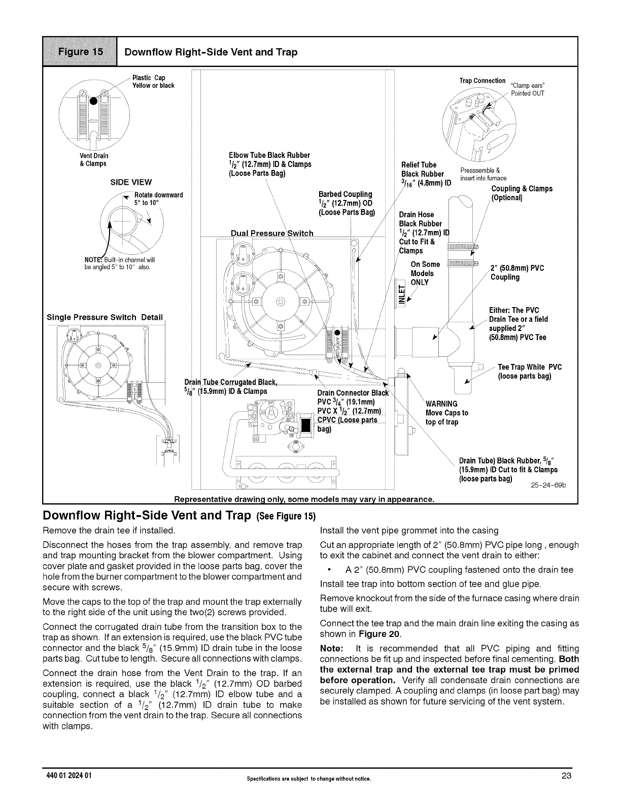
_i_i_i_!_!_i_i_i_i_i_;;_!_i_i_i_i_!
_!_I_11_ii_! Downflow Right-Side Vent and Trap
iiiiiiiiiiiiiiiiiiiiiiiiiiiiiiiiiiiiiiiiiiiiiiiiiiiiiiiiiiiiiiiiiiiiiiii
(15.9mm)ID Cut to fit &Clamps
(loosepartsbag) 25-24-60b
Representativedrawing only, some models mayvary in appearance,
Downflow Right-Side Vent and Trap (SeeFigure15)
Remove the drain tee if installed.
Disconnect the hoses from the trap assembly, and remove trap
and trap mounting bracket from the blower compartment. Using
cover plate and gasket provided in the loose parts bag, cover the
hole from the burner compartment to the blower compartment and
secure with screws.
Move the caps to the top of the trap and mount the trap externally
to the right side of the unit using the two(2) screws provided.
Connect the corrugated drain tube from the transition box to the
trap as shown. If an extension is required, use the black PVC tube
connector and the black 5/8" (15.9mm) ID drain tube inthe loose
parts bag. Cut tube to length. Secure all connections with clamps.
Connect the drain hose from the Vent Drain to the trap. If an
extension is required, use the black 1/2" (12.7mm) OD barbed
coupling, connect a black 1/2" (12.7mm) ID elbow tube and a
suitable section of a 1/2" (12.7mm) ID drain tube to make
connection from the vent drain to the trap. Secure all connections
with clamps.
Install the vent pipe grommet into the casing
Cut an appropriate length of 2" (50.8mm) PVC pipe long, enough
to exit the cabinet and connect the vent drain to either:
•A 2" (50.8mm) PVC coupling fastened onto the drain tee
Install tee trap into bottom section of tee and glue pipe.
Remove knockout from the side of the furnace casing where drain
tube will exit.
Connect the tee trap and the main drain line exiting the casing as
shown in Figure 20.
Note: It is recommended that all PVC piping and fitting
connections be fit up and inspected before final cementing. Both
the external trap and the external tee trap must be primed
before operation, Verify all condensate drain connections are
securely clamped. A coupling and clamps (in loose part bag) may
be installed as shown for future servicing of the vent system.
440 01 202401 Specificationsare subject to changewithout notice. 23
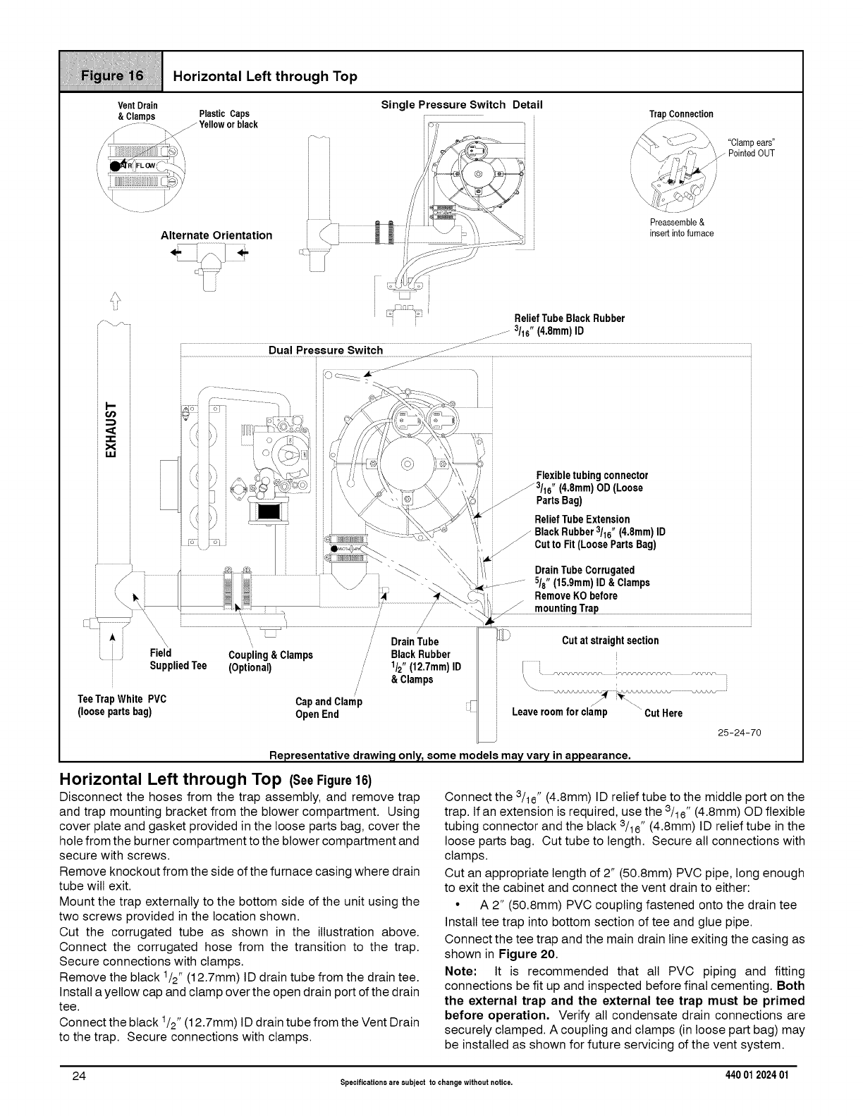
iiiiiiiiiiiiiiiii_;iiili!!I_i_i!_ii_iji_iiiiiiiiiiii!iiii_i!ii_ii_iiii!!iii_iiiS_i_i_ii!iii1iiii_iiiiii!ii_i!;!i
iiiiii_iiiiiiiiiiiiI/_I_iiii_/_ _i_ _ H orizonta_ Left th rough Top
Horizontal Left through Top (SeeFigure16)
Disconnect the hoses from the trap assembly, and remove trap
and trap mounting bracket from the blower compartment. Using
cover plate and gasket provided in the loose parts bag, cover the
hole from the burner compartment to the blower compartment and
secure with screws.
Remove knockout from the side of the furnace casing where drain
tube will exit.
Mount the trap externally to the bottom side of the unit using the
two screws provided in the location shown.
Cut the corrugated tube as shown in the illustration above.
Connect the corrugated hose from the transition to the trap.
Secure connections with clamps.
Remove the black 1/2" (12.7mm) ID drain tube from the drain tee.
Install a yellow cap and clamp over the open drain port of the drain
tee.
Connect the black 1/2" (12.7mm) ID drain tube from the Vent Drain
to the trap. Secure connections with clamps.
Connect the 3/16" (4.8mm) ID relief tube to the middle port on the
trap. If an extension is required, use the 3/16" (4.8mm) OD flexible
tubing connector and the black 3/16" (4.8mm) ID relief tube in the
loose parts bag. Cut tube to length. Secure all connections with
clamps.
Cut an appropriate length of 2" (50.8mm) PVC pipe, long enough
to exit the cabinet and connect the vent drain to either:
•A 2" (50.8mm) PVC coupling fastened onto the drain tee
Install tee trap into bottom section of tee and glue pipe.
Connect the tee trap and the main drain line exiting the casing as
shown in Figure 20.
Note: It is recommended that all PVC piping and fitting
connections be fit up and inspected before final cementing. Both
the external trap and the external tee trap must be primed
before operation, Verify all condensate drain connections are
securely clamped. A coupling and clamps (in loose part bag) may
be installed as shown for future servicing of the vent system.
24 Specificationsare subject to changewithout notice. 440 012024 01
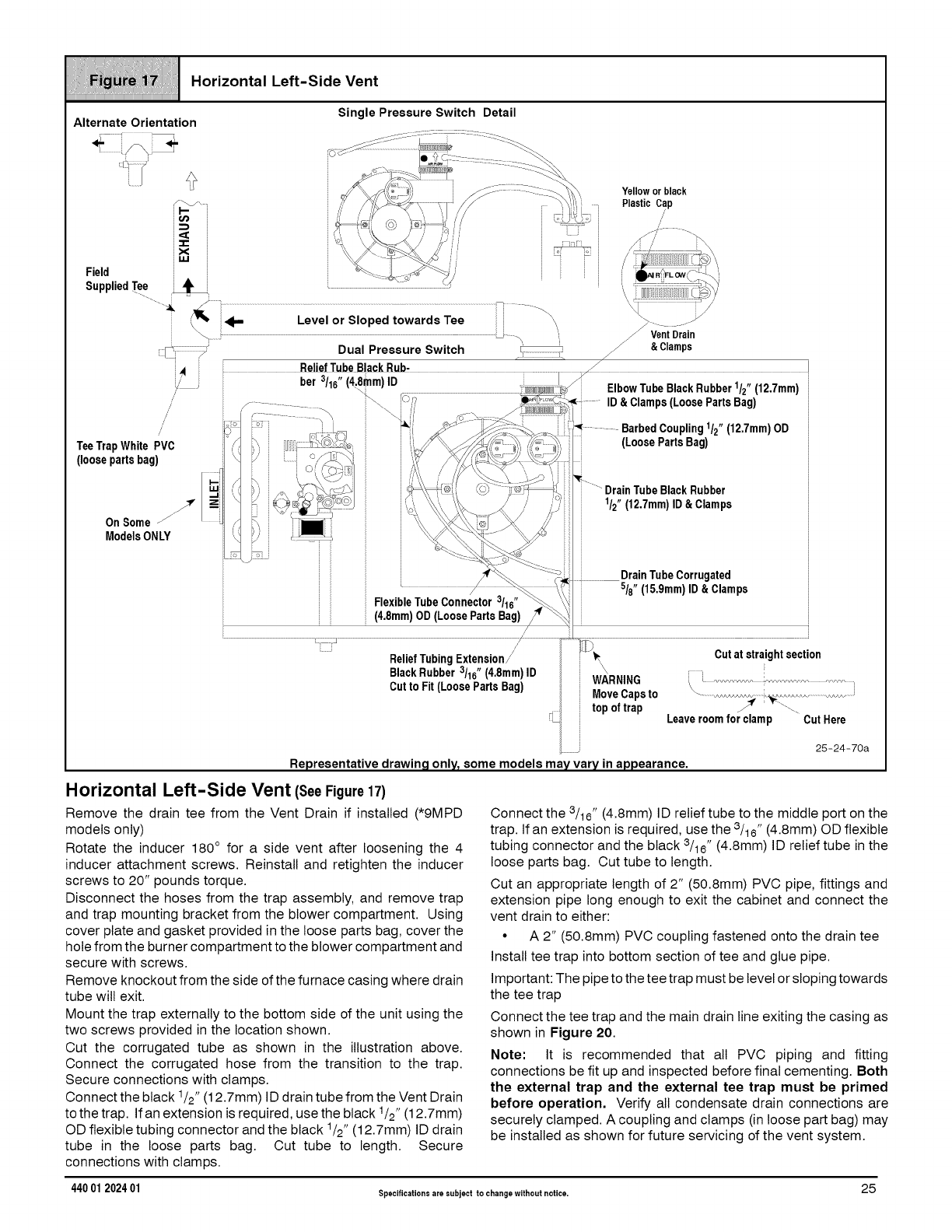
iiiiiiiiiiiiiiiiiiiiiYiiiiiiiii!iiiiiii_iiiiiiiiiiiii!!ii_X'iiiiiiii!iiii_i,iiiY!Siiiiiiiiiiiiii_iiiiiii_iiiiiiii_'iiii/_ii
iiiiiiiiiiiiiiiiiiiiiiiiiiiiiiiiiiiiiiiiiiiiiiiiiiiiiiiiiiiiiiiiiiiiiiiiiiiiiiiiiiiiiiiiiiiiiiiiiiiiiiiiiiiiiiiiiiiiiiiiiiiiiiiiiiiiiiiiiiiiiiii
Horizontal Left-Side Vent (SeeFigure17)
Remove the drain tee from the Vent Drain if installed (*9MPD
models only)
Rotate the inducer 180 ° for a side vent after loosening the 4
inducer attachment screws. Reinstall and retighten the inducer
screws to 20" pounds torque.
Disconnect the hoses from the trap assembly, and remove trap
and trap mounting bracket from the blower compartment. Using
cover plate and gasket provided in the loose parts bag, cover the
hole from the burner compartment to the blower compartment and
secure with screws.
Remove knockout from the side of the furnace casing where drain
tube will exit.
Mount the trap externally to the bottom side of the unit using the
two screws provided in the location shown.
Cut the corrugated tube as shown in the illustration above.
Connect the corrugated hose from the transition to the trap.
Secure connections with clamps.
Connect the black 1/2" (12.7mm) ID drain tube from the Vent Drain
to the trap. If an extension is required, use the black 1/2" (12.7mm)
OD flexible tubing connector and the black 1/2" (12.7mm) ID drain
tube in the loose parts bag. Cut tube to length. Secure
connections with clamps.
Connect the 3/16" (4.8mm) ID relief tube to the middle port on the
trap. If an extension is required, use the 3/16" (4.8mm) OD flexible
tubing connector and the black 3/16" (4.8mm) ID relief tube in the
loose parts bag. Cut tube to length.
Cut an appropriate length of 2" (50.8mm) PVC pipe, fittings and
extension pipe long enough to exit the cabinet and connect the
vent drain to either:
• A 2" (50.8mm) PVC coupling fastened onto the drain tee
Install tee trap into bottom section of tee and glue pipe.
Important: The pipe to the tee trap must be level or sloping towards
the tee trap
Connect the tee trap and the main drain line exiting the casing as
shown in Figure 20.
Note: It is recommended that all PVC piping and fitting
connections be fit up and inspected before final cementing. Both
the external trap and the external tee trap must be primed
before operation, Verify all condensate drain connections are
securely clamped. A coupling and clamps (in loose part bag) may
be installed as shown for future servicing of the vent system.
440 01 202401 Specificationsare subject to changewithout notice. 25
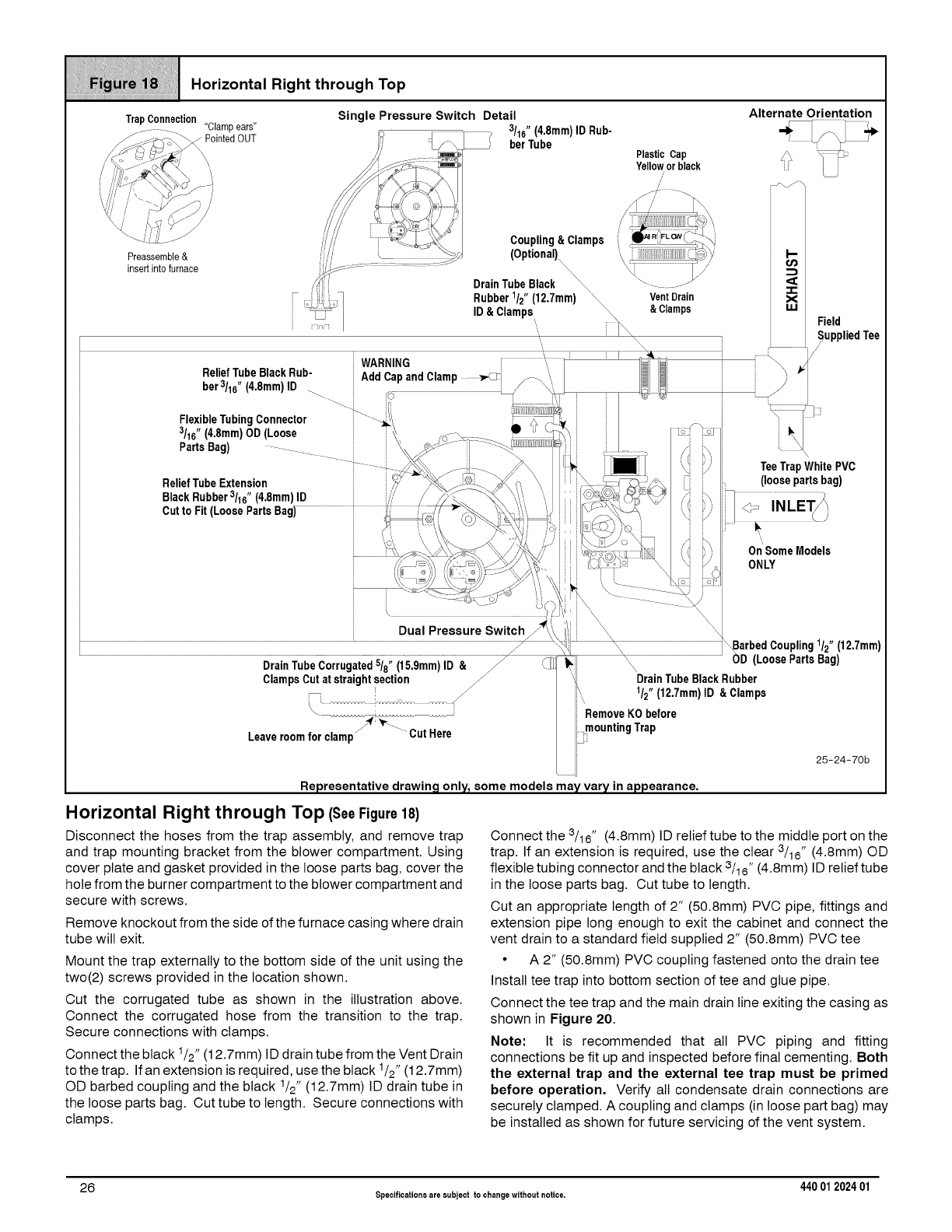
/i/ii///il;ii!!/iiil!l;iii!iiiiilii/!i//iiiili}//lliil;ili//!!
! .o.zon=t. oo .
TrapConnection Single Pressure Switch Detail Alternate Orientation
"Clampears"
Horizontal Right through Top (SeeFigure18)
Disconnect the hoses from the trap assembly, and remove trap
and trap mounting bracket from the blower compartment. Using
cover plate and gasket provided in the loose parts bag, cover the
hole from the burner compartment to the blower compartment and
secure with screws.
Remove knockout from the side of the furnace casing where drain
tube will exit.
Mount the trap externally to the bottom side of the unit using the
two(2) screws provided in the location shown.
Cut the corrugated tube as shown in the illustration above.
Connect the corrugated hose from the transition to the trap.
Secure connections with clamps.
Connect the black 1/2" (12.7mm) ID drain tube from the Vent Drain
to the trap. If an extension is required, use the black 1/2" (12.7mm)
OD barbed coupling and the black 1/2" (12.7mm) ID drain tube in
the loose parts bag. Cut tube to length. Secure connections with
clamps.
Connect the 3/16" (4.8mm) ID relief tube to the middle port on the
trap. If an extension is required, use the clear 3/16" (4.8mm) OD
flexible tubing connector and the black 3/16" (4.8mm) ID relief tube
in the loose parts bag. Cut tube to length.
Cut an appropriate length of 2" (50.8mm) PVC pipe, fittings and
extension pipe long enough to exit the cabinet and connect the
vent drain to a standard field supplied 2" (50.8mm) PVC tee
• A 2" (50.8mm) PVC coupling fastened onto the drain tee
Install tee trap into bottom section of tee and glue pipe.
Connect the tee trap and the main drain line exiting the casing as
shown in Figure 20.
Note: It is recommended that all PVC piping and fitting
connections be fit up and inspected before final cementing. Both
the external trap and the external tee trap must be primed
before operation, Verify all condensate drain connections are
securely clamped. A coupling and clamps (in loose part bag) may
be installed as shown for future servicing of the vent system.
26 Specificationsare eubject to changewithout notice. 440 012024 01
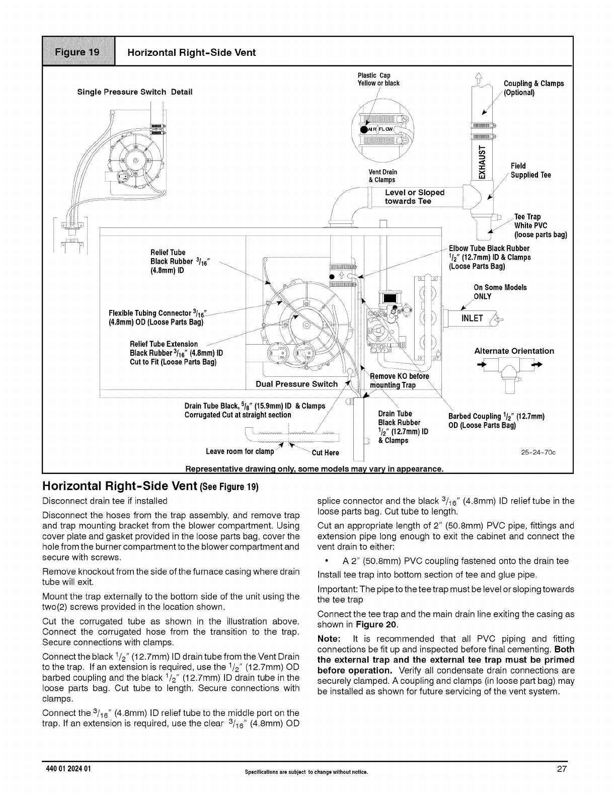
Horizontal Right-Side Vent
Single Pressure Switch Detail
Plastic Cap
Yellowor black
/
/
Coupling&Clamps
(Optional)
.. J Field
VentDrain _Supplied Tee
&Clamps /
z ..................)°wardsTee...........................................
J_/)::y) .TeeTrap
...................................--= _ _ [ .-'_ WhitePVC
& Clamps
25-24-70c
Representative drawing only_ some models may vary in appearance,
Horizontal Right-Side Vent (See Figure19)
Disconnect drain tee if installed
Disconnect the hoses from the trap assembly, and remove trap
and trap mounting bracket from the blower compartment. Using
cover plate and gasket provided in the loose parts bag, cover the
hole from the burner compartment to the blower compartment and
secure with screws.
Remove knockout from the side of the furnace casing where drain
tube will exit.
Mount the trap externally to the bottom side of the unit using the
two(2) screws provided in the location shown.
Cut the corrugated tube as shown in the illustration above.
Connect the corrugated hose from the transition to the trap.
Secure connections with clamps.
Connect the black 1/2" (12.7mm) ID drain tube from the Vent Drain
to the trap. Ifan extension is required, use the 1/2" (12.7mm) OD
barbed coupling and the black 1/2" (12.7mm) ID drain tube in the
loose parts bag. Cut tube to length. Secure connections with
clamps.
Connect the 3/16" (4.8mm) ID relief tube to the middle port on the
trap. If an extension is required, use the clear 3/16" (4.8mm) OD
splice connector and the black 3/16'' (4.8mm) ID relief tube in the
loose parts bag. Cut tube to length.
Cut an appropriate length of 2" (50.8mm) PVC pipe, fittings and
extension pipe long enough to exit the cabinet and connect the
vent drain to either:
• A 2" (50.8mm) PVC coupling fastened onto the drain tee
Install tee trap into bottom section of tee and glue pipe.
Important: The pipe to the tee trap must be level or sloping towards
the tee trap
Connect the tee trap and the main drain line exiting the casing as
shown in Figure 20.
Note: It is recommended that all PVC piping and fitting
connections be fit up and inspected before final cementing. Both
the external trap and the external tee trap must be primed
before operation. Verify all condensate drain connections are
securely clamped. A coupling and clamps (in loose part bag) may
be installed as shown for future servicing of the vent system.
440 01 202401 Specificationsare subject to changewithout notice. 27
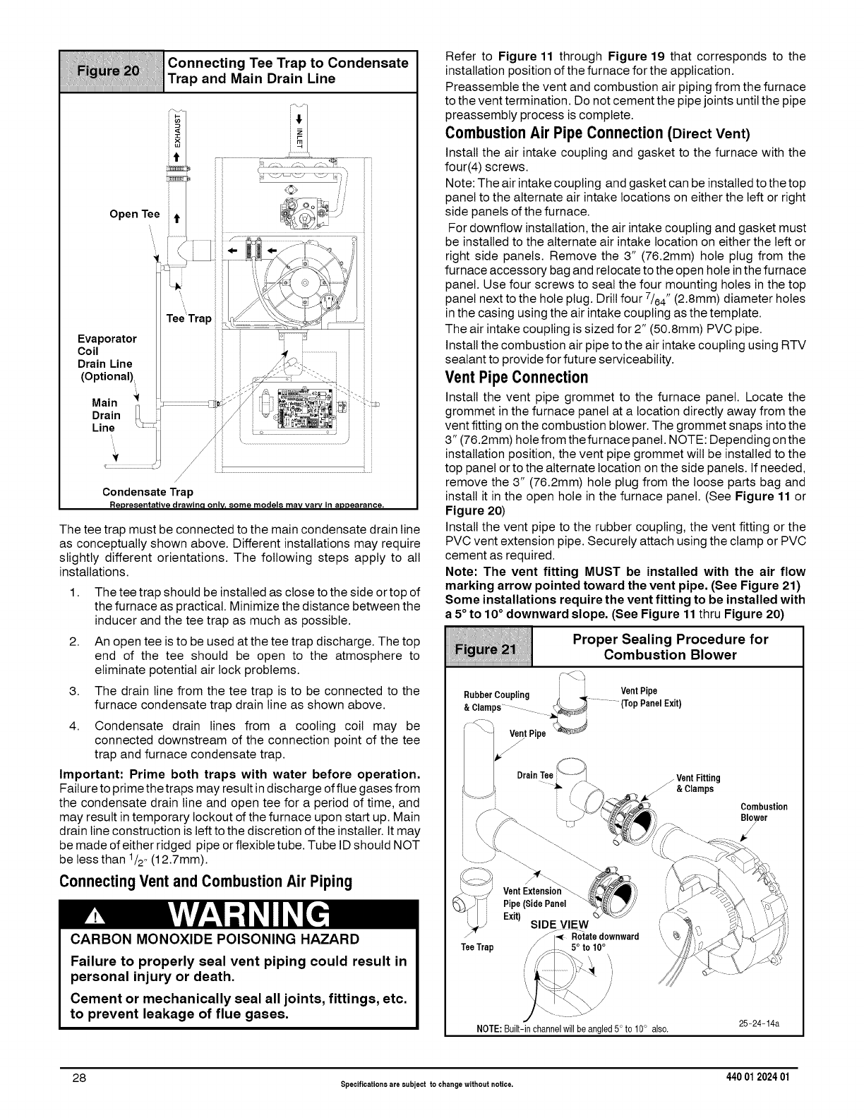
iiiiii!!iiiiiii!iiiiii_iiiii!ii__ii[iiiiiiii_I!i_;1iiiiiii_i!iiiiiiiiiiii_i1iiiii_iiiIiii_iii!!!iiiii_iii1i!!!iiiiYi1iiIiIiii;_
Connecting Tee Trap to Condensate
Trap and Main Drain Line
Open Tee
it
it
/
Condensate Trap
Representative drawinq only_ some models may vary in appearance,
The tee trap must be connected to the main condensate drain line
as conceptually shown above. Different installations may require
slightly different orientations. The following steps apply to all
installations.
1. The tee trap should be installed as close to the side or top of
the furnace as practical. Minimize the distance between the
inducer and the tee trap as much as possible.
2. An open tee is to be used at the tee trap discharge. The top
end of the tee should be open to the atmosphere to
eliminate potential air lock problems.
3. The drain line from the tee trap is to be connected to the
furnace condensate trap drain line as shown above.
4. Condensate drain lines from a cooling coil may be
connected downstream of the connection point of the tee
trap and furnace condensate trap.
Important: Prime both traps with water before operation.
Failure to prime the traps may result in discharge of flue gases from
the condensate drain line and open tee for a period of time, and
may result in temporary lockout of the furnace upon start up. Main
drain line construction is left to the discretion of the installer. It may
be made of either ridged pipe or flexible tube. Tube ID should NOT
be less than 1/2, (12.7mm).
ConnectingVent and Combustion Air Piping
CARBON MONOXIDE POISONING HAZARD
Failure to properly seal vent piping could result in
personal injury or death.
Cement or mechanically seal all joints, fittings, etc.
to prevent leakage of flue gases.
Refer to Figure 11 through Figure 19 that corresponds to the
installation position of the furnace for the application.
Preassembte the vent and combustion air piping from the furnace
to the vent termination. Do not cement the pipe joints until the pipe
preassembly process is complete.
Combustion Air Pipe Connection (Direct Vent)
Install the air intake coupling and gasket to the furnace with the
four(4) screws.
Note: The air intake coupling and gasket can be installed to the top
panel to the alternate air intake locations on either the left or right
side panels of the furnace.
For downflow installation, the air intake coupling and gasket must
be installed to the alternate air intake location on either the left or
right side panels. Remove the 3" (76.2mm) hole plug from the
furnace accessory bag and relocate to the open hole in the furnace
panel. Use four screws to seal the four mounting holes in the top
panel next to the hole plug. Drill four 7/64" (2.8mm) diameter holes
in the casing using the air intake coupling as the template.
The air intake coupling is sized for 2" (50.8mm) PVC pipe.
Install the combustion air pipe to the air intake coupling using RTV
sealant to provide for future serviceability.
Vent Pipe Connection
Install the vent pipe grommet to the furnace panel. Locate the
grommet in the furnace panel at a location directly away from the
vent fitting on the combustion blower. The grommet snaps into the
3" (76.2mm) hole from the furnace panel. NOTE: Depending on the
installation position, the vent pipe grommet will be installed to the
top panel or to the alternate location on the side panels. If needed,
remove the 3" (76.2mm) hole plug from the loose parts bag and
install it in the open hole in the furnace panel. (See Figure 11 or
Figure 20)
Install the vent pipe to the rubber coupling, the vent fitting or the
PVC vent extension pipe. Securely attach using the clamp or PVC
cement as required.
Note: The vent fitting MUST be installed with the air flow
marking arrow pointed toward the vent pipe. (See Figure 21)
Some installations require the vent fitting to be installed with
a 5°to 10°downward slope. (See Figure 11thru Figure 20)
ro erSeo.ng rooe.ure,or
Combustion Blower
Rubber Coupling i ._ Vent Pipe
_ .... (Top Panel Exit)
&Clamps
_-, VejntPipe _:_:
S
NOTE: Built-in channelwill be angled 5° to 10° also. 25-24-14a
28 Specificationsare subject to changewithout notice. 440 012024 01
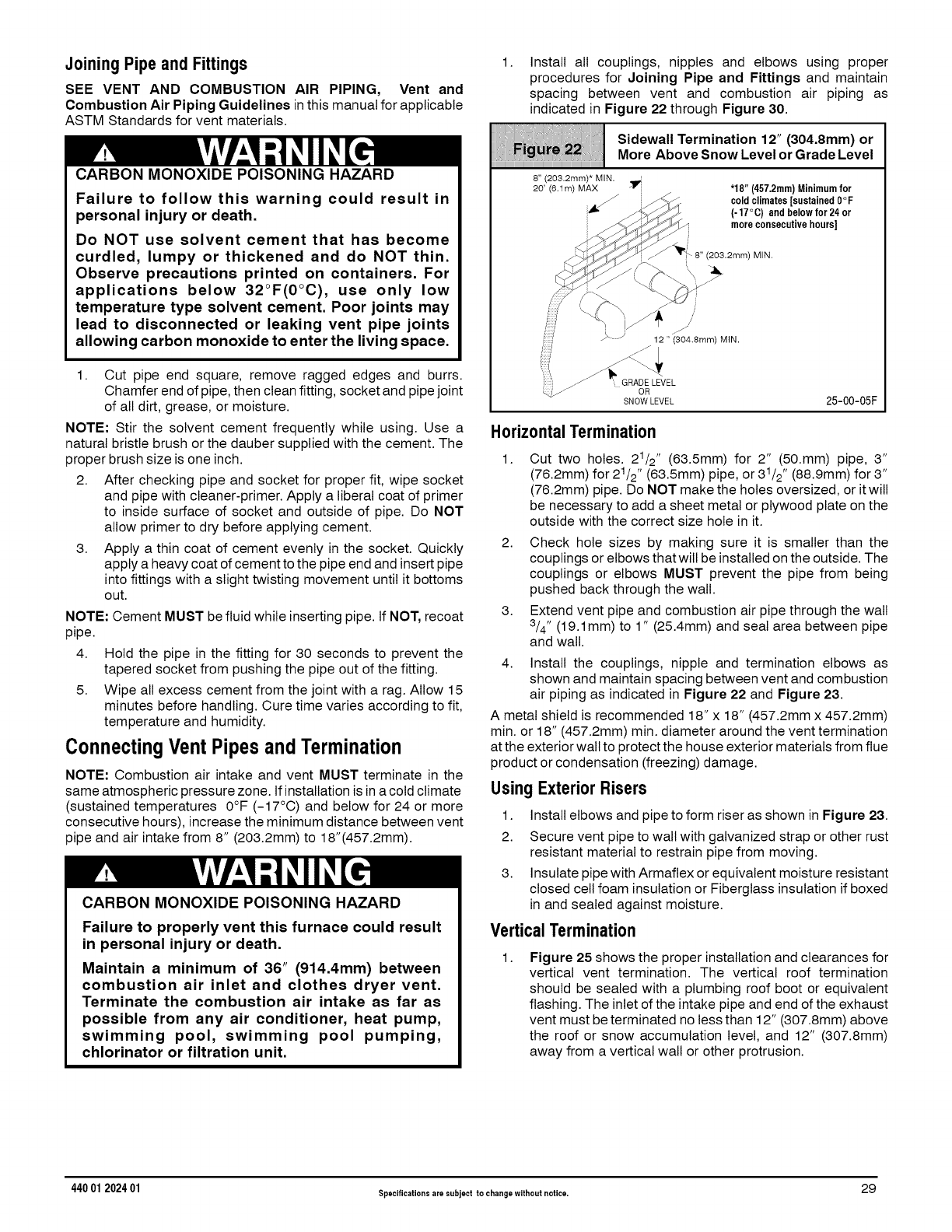
Joining Pipe and Fittings
SEE VENT AND COMBUSTION AIR PIPING, Vent and
Combustion Air Piping Guidelines inthis manual for applicable
ASTM Standards for vent materials.
CARBON MONOXIDE POISONING HAZARD
Failure to follow this warning could result in
personal injury or death.
Do NOT use solvent cement that has become
curdled, lumpy or thickened and do NOT thin.
Observe precautions printed on containers. For
applications below 32°F(0°C), use only low
temperature type solvent cement. Poor joints may
lead to disconnected or leaking vent pipe joints
allowing carbon monoxide to enter the living space.
1. Cut pipe end square, remove ragged edges and burrs.
Chamfer end of pipe, then clean fitting, socket and pipe joint
of all dirt, grease, or moisture.
NOTE: Stir the solvent cement frequently while using. Use a
natural bristle brush or the dauber supplied with the cement. The
proper brush size is one inch.
2. After checking pipe and socket for proper fit, wipe socket
and pipe with cleaner-primer. Apply a liberal coat of primer
to inside surface of socket and outside of pipe. Do NOT
allow primer to dry before applying cement.
3. Apply a thin coat of cement evenly in the socket. Quickly
apply a heavy coat of cement to the pipe end and insertpipe
into fittings with a slight twisting movement until it bottoms
out.
NOTE: Cement MUST be fluid while inserting pipe. If NOT, recoat
pipe.
4. Hold the pipe in the fitting for 30 seconds to prevent the
tapered socket from pushing the pipe out of the fitting.
5. Wipe all excess cement from the joint with a rag. Allow 15
minutes before handling. Cure time varies according to fit,
temperature and humidity.
ConnectingVent Pipes andTermination
NOTE: Combustion air intake and vent MUST terminate in the
same atmospheric pressure zone. If installation isin a cold climate
(sustained temperatures 0°F (-17°C) and below for 24 or more
consecutive hours), increase the minimum distance between vent
pipe and air intake from 8" (203.2mm) to 18"(457.2mm).
CARBON MONOXIDE POISONING HAZARD
Failure to properly vent this furnace could result
in personal injury or death.
Maintain a minimum of 36" (914.4mm) between
combustion air inlet and clothes dryer vent.
Terminate the combustion air intake as far as
possible from any air conditioner, heat pump,
swimming pool, swimming pool pumping,
chlorinator or filtration unit.
1. Install all couplings, nipples and elbows using proper
procedures for Joining Pipe and Fittings and maintain
spacing between vent and combustion air piping as
indicated in Figure 22 through Figure 30.
Sidewall Termination 12" (304.8mm)or
More Above Snow Level or Grade Level
8" (203.2mm)* MIN.
20' (6.1m) MAX 7'_ '18" (457.2mm) Minimum for
ii J_" coldclimates [sustained0°F
_i (-17°0) and below for 24or
more consecutivehours]
j 8" (203.2mm) MIN.
":::_ J\ /12 " (304.8mm) MIN.
_-_ _ GRADE LEVEL
SNOW LEVEL 25-00-05F
Horizontal Termination
1. Cut two holes. 21/2,' (63.5mm) for 2" (50.mm) pipe, 3"
(76.2mm) for 21/2" (63.5mm) pipe, or 31/2 ,' (88.9mm) for 3"
(76.2mm) pipe. Do NOT make the holes oversized, or it will
be necessary to add a sheet metal or plywood plate on the
outside with the correct size hole in it.
2. Check hole sizes by making sure it is smaller than the
couplings or elbows that will be installed on the outside. The
couplings or elbows MUST prevent the pipe from being
pushed back through the wall.
3. Extend vent pipe and combustion air pipe through the wall
3/4" (19.1mm) to 1" (25.4mm) and seal area between pipe
and wall.
4. Install the couplings, nipple and termination elbows as
shown and maintain spacing between vent and combustion
air piping as indicated in Figure 22 and Figure 23.
A metal shield is recommended 18" x 18" (457.2mm x 457.2mm)
min. or 18" (457.2mm) min. diameter around the vent termination
at the exterior walt to protect the house exterior materials from flue
product or condensation (freezing) damage.
Using Exterior Risers
1. Install elbows and pipe to form riser as shown in Figure 23.
2. Secure vent pipe to wall with galvanized strap or other rust
resistant material to restrain pipe from moving.
3. Insulate pipe with Armaflex or equivalent moisture resistant
closed cell foam insulation or Fiberglass insulation if boxed
in and sealed against moisture.
Vertical Termination
1. Figure 25 shows the proper installation and clearances for
vertical vent termination. The vertical roof termination
should be sealed with a plumbing roof boot or equivalent
flashing. The inlet of the intake pipe and end of the exhaust
vent must be terminated no less than 12" (307.8mm) above
the roof or snow accumulation level, and 12" (307.8mm)
away from a vertical wall or other protrusion.
440 01 202401 Specificationsare subject to changewithout notice. 29
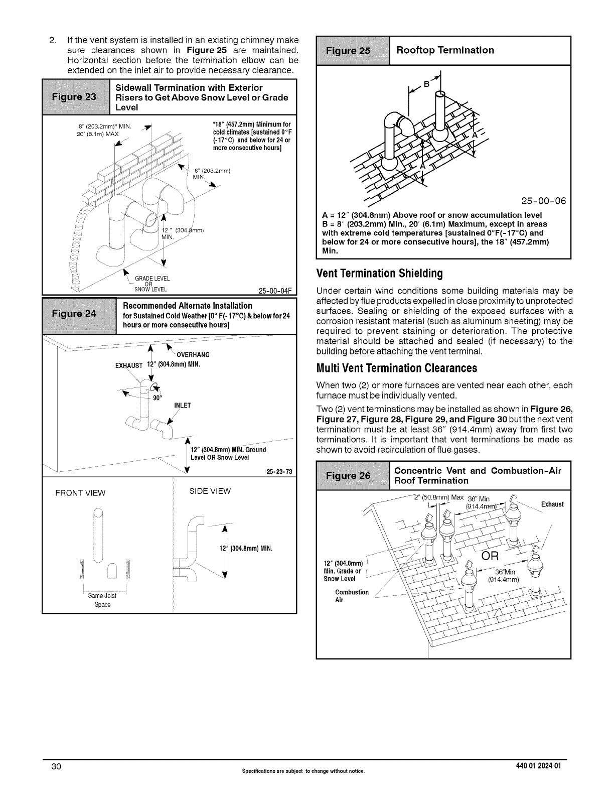
2. If the vent system is installed in an existing chimney make
sure clearances shown in Figure25 are maintained.
Horizontal section before the termination elbow can be
extended on the inlet air to provide necessary clearance.
Sidewall Termination with Exterior
Risers to Get Above Snow Level or Grade
Level
8" (203.2mm)* MIN.
2O' (6.1m) MAX
'18" (457.2mm)Minimumfor
coldclimates [sustained0°F
(-17°C) and below for 24 or
more consecutivehours]
, 8" (203.2mm)
MIN.
!
2 )
25-00-04F
Recommended Alternate Installation
for SustainedColdWeather[0°F(- 17°C)&belowfor 24
hoursor moreconsecutivehours]
EXHAUST 12" (304.8mm)MIN.
FRONT VIEW
/-y
\)
Same Joist
Space
SlDE VlEW
Rooftop Termination
________________________________________________________________________________________________________________________________________________
25 O0 06
_'i!_ :c. our., tduhoeem°ii!ii!(!iiadms)
Vent Termination Shielding
Under certain wind conditions some building materials may be
affected by flue products expelled in close proximity to unprotected
surfaces. Sealing or shielding of the exposed surfaces with a
corrosion resistant material (such as aluminum sheeting) may be
required to prevent staining or deterioration. The protective
material should be attached and sealed (if necessary) to the
building before attaching the vent terminal.
Multi Vent Termination Clearances
When two (2) or more furnaces are vented near each other, each
furnace must be individually vented.
Two (2) vent terminations may be installed as shown in Figure 26,
Figure 27, Figure 28, Figure 29, and Figure 30 but the next vent
termination must be at least 36" (914.4mm) away from first two
terminations. It is important that vent terminations be made as
shown to avoid recirculation of flue gases.
iiiHiii!iiii ii!Tiiiiiii
________________________________________________________________________________________________________________________________________________
._7- JJ'-'-"' -
s°"nw 2:L'
Concentric Vent and Combustion-Air
Roof Termination
Max 36" Min
30 Specifications are subject to changewithout notice. 440 012024 01
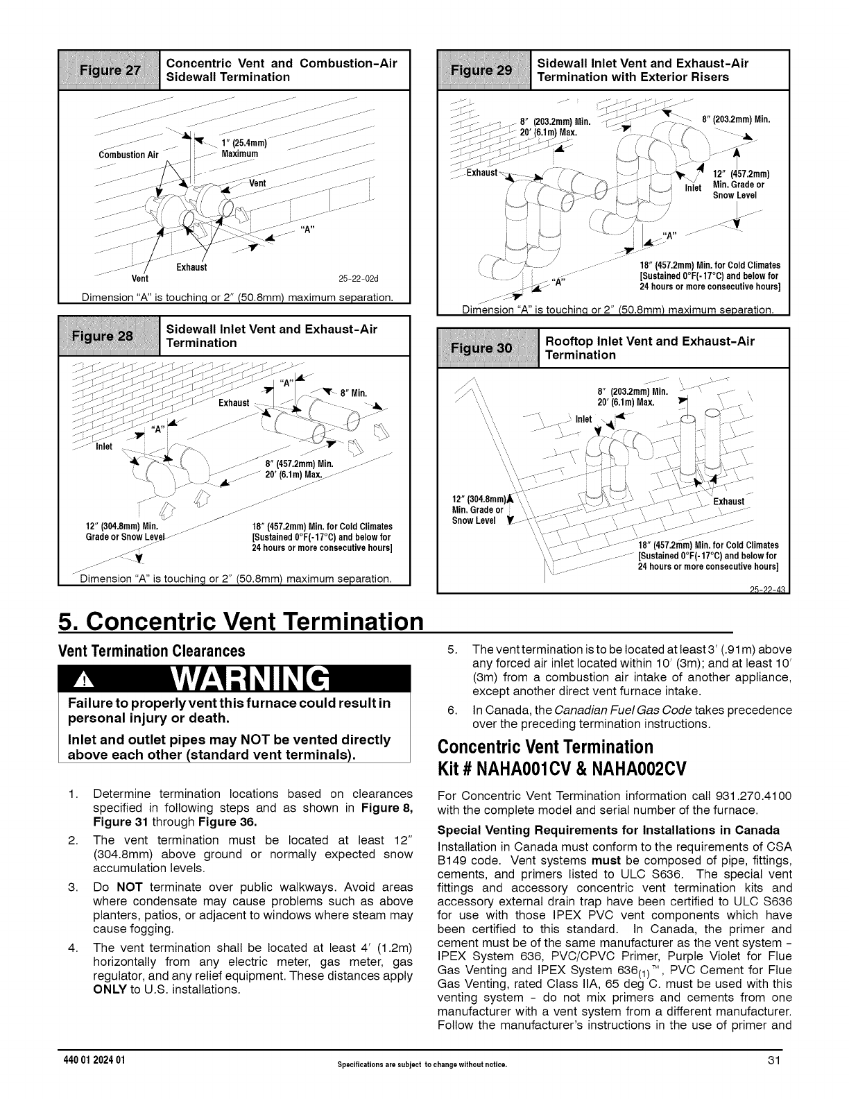
Concentric Vent and Com bustion-Air
................................................................................................................................................Sidewall Termination
iiiiiiiiiiiiiiiiiiiiiiiiiiiiiiiiiiiiiiiiiiiiiiiiiiiiiiiiiiiiiiiiiiiiiiii
.... - j__- ._j.J_-
..... _.-----_- j JJ .fj ._- J _.... .-J_
j jjJJJ- .____ ......
/JJ j z- .......
j .... J_
.... .......""-_i _._,, (25.4mm)................-...........
CombustionAir _-J- Maximum ..............
Vent 25-22-02d
Dimension "A" is touchin.q or 2" (50.8mm) maximum separation.
i!' Sidewall Inlet Vent and Exhaust-Air
................................................................................................................................................Termination
iiiiiiiiiiiiiiiiiiiiiiiiiiiiiiiiiiiiiiiiiiiiiiiiiiiiiiiiiiiiiiiiiiiiiiii
.s_.> Z i'_<-- j _-%J<_ J- . f ._z-_jJ __ / J'_F 8 Mln
"J" _-"'-r-_--s'T- -<J--_"7- --j Exhaust .... "W_ - .
.... --< J_ "A...... /Q -:-- :{]]J '_\
k _ _ _ _ ........ _........ 20'(6,1m) Max............
12"(304.8mm) Min. ........... 18" (457.2mm) Min. for Cold Climates
Grade or Snow Lev_LJ.... [Sustained0°F(-17°C)and below for
/24 hours or more consecutivehours]
jj.JJDimension 'W' is touching or 2" (50.8mm) maximum separation.
Sidewall Inlet Vent and Exhaust-Air
....................................................................................................................................Termination with Exterior Risers
iiiiiiiiiiiiiiiiiiiiiiiiiiiiiiiiiiiiiiiiiiiiiiiiiiiiiiiiiiiiiiiiii
-
;_ ___ _ 8" (203.2mm)Min. _._-_ .... .-_ _- 8" (203.2mm)Mm,
....:i_ _7.- _ -i---20'(6.1m) Max. --'_.-_ /" ,1 F_.\ Ji
:;-_---_M;%_-O-';---<%.... /' _ '_-L .....
--_ _--J- i k ._7\ -jk y "t
;;7 Exhaust \i :::: -j_ /_ __ ___--j ..... r'_P_./ 12" (457.2mm)
7" 7-_ ' 1"] -_-i _ _ In/at Mn Gradeor
.i, /_ __;J_j _. Snow Level
i k _ ........ f---¥
'L _ __ _A I "A..... ---
1"]_" "_- -/ 18" (457.2mm)Min. for Cold Climates
L {_ . . "A;; [Sustained0°F(- 17°C) and belowfor
_--_ .... 24 hoursor moreconsecutivehours]
_/: T-_IV
Dimension"A" is touohinq or 2" (50.8mm) maximum separation.
iMIIiiiiiiIIiiiMI{!!i1i1liiIiiiiiiilll}illiiiiiiliiiiiiIiitiiiiiD:;iiiiilliiiiIJi
, Roo.opInletVentandExhaust-A,r
................................................................................................................................................Termination
\\ 8" (203.2mm)-Mi-n] "-Y-/',-;_-] I-- ,,
\, \, 20' (6,1m)Max. _" \,,. .... "
\,,\\ .......t ___,Inlet _ll i_-- ,__.;_ _]__---"-' ....
', ' _.__J- \ _l -- .....
\ \, . -......', _-k---f- i ....--" :-c.M',_,L-_;,7x
'\ Y-" "......... J \, "t,k 41_)x4- -b--_
12" 1304.8mm1_"\\, '_I._"",,_ _¢ ;' _*---x ........ "_EExhaust
Min. Grade or ',, \, _J-T--', ........... _",---_,.- ",.---_- ',............
Snow Level _---'_',]x',7°-_7'---_;'s_-,,....... ql- _--'Y--'+{('" _-"........... _....
'\,\',c---}s-J"_j-. _' ........... 18" (457.2m-m)-Mln,for Cold Climates
\ '%_...... '--- _.............. [Sustained0°F(-17°C) and belowfor
i"YI.................. 24 hoursor more consecutivehours]
26-22-43
5. Concentric Vent Termination
Vent Termination Clearances
Failure to properly vent this furnace could result in
personal injury or death.
Inlet and outlet pipes may NOT be vented directly
above each other (standard vent terminals).
5. The venttermination is to be located at least 3' (.91 m) above
any forced air inlet located within 10' (3m); and at least 10'
(3m) from a combustion air intake of another appliance,
except another direct vent furnace intake.
6. In Canada, the Canadian Fuel Gas Code takes precedence
over the preceding termination instructions.
ConcentricVentTermination
Kit #NAHA001CV& NAHA002CV
1. Determine termination locations based on clearances
specified in following steps and as shown in Figure 8,
Figure 31 through Figure 36.
2. The vent termination must be located at least 12"
(304.8mm) above ground or normally expected snow
accumulation levels.
3. Do NOT terminate over public walkways. Avoid areas
where condensate may cause problems such as above
planters, patios, or adjacent to windows where steam may
cause fogging.
4. The vent termination shall be located at least 4' (1.2m)
horizontally from any electric meter, gas meter, gas
regulator, and any relief equipment. These distances apply
ONLY to U.S. installations.
For Concentric Vent Termination information call 931.270.4100
with the complete model and serial number of the furnace.
Special Venting Requirements for Installations in Canada
Installation in Canada must conform to the requirements of CSA
B149 code. Vent systems must be composed of pipe, fittings,
cements, and primers listed to ULC S636. The special vent
fittings and accessory concentric vent termination kits and
accessory external drain trap have been certified to ULC S636
for use with those IPEX PVC vent components which have
been certified to this standard. In Canada, the primer and
cement must be of the same manufacturer as the vent system -
IPEX System 636, PVC/CPVC Primer, Purple Violet for Flue
Gas Venting and IPEX System 636(1) TM, PVC Cement for Flue
Gas Venting, rated Class IIA, 65 deg C. must be used with this
venting system - do not mix primers and cements from one
manufacturer with a vent system from a different manufacturer.
Follow the manufacturer's instructions in the use of primer and
440 01 202401 Specifications are subject to changewithout notice. 31
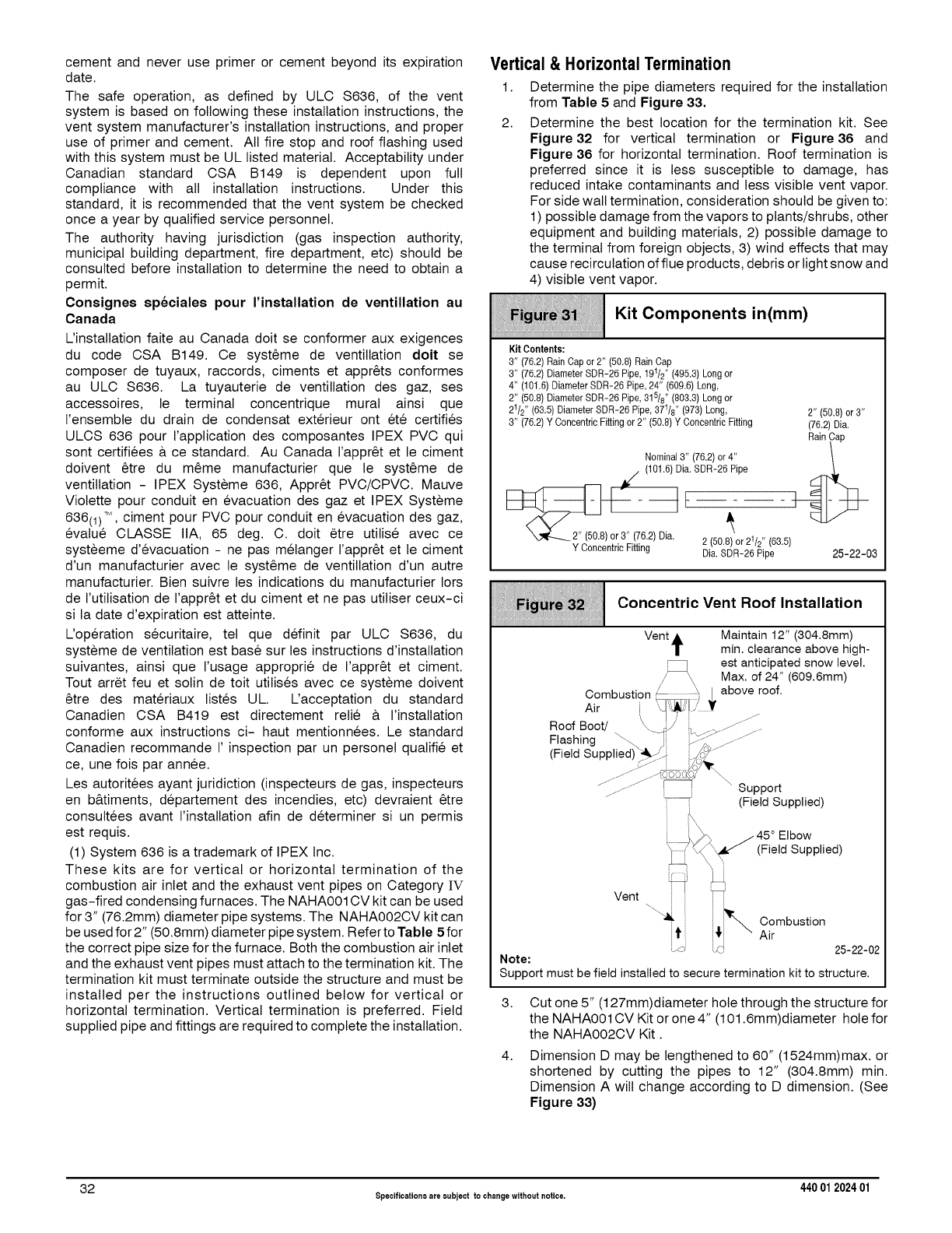
cement and never use primer or cement beyond its expiration
date.
The safe operation, as defined by ULC $636, of the vent
system is based on following these installation instructions, the
vent system manufacturer's installation instructions, and proper
use of primer and cement. All fire stop and roof flashing used
with this system must be UL listed material. Acceptability under
Canadian standard CSA B149 is dependent upon full
compliance with all installation instructions. Under this
standard, it is recommended that the vent system be checked
once a year by qualified service personnel.
The authority having jurisdiction (gas inspection authority,
municipal building department, fire department, etc) should be
consulted before installation to determine the need to obtain a
permit.
Consignes sp6ciales pour I'installation de ventillation au
Canada
L'installation faite au Canada doit se conformer aux exigences
du code CSA B149. Ce syst_me de ventillation dolt se
composer de tuyaux, raccords, ciments et appr_ts conformes
au ULC $636. La tuyauterie de ventillation des gaz, ses
accessoires, le terminal concentrique mural ainsi que
I'ensembte du drain de condensat exterieur ont et6 certifies
ULCS 636 pour I'application des composantes IPEX PVC qui
sont certifiees & ce standard. Au Canada I'appr_t et le ciment
doivent _tre du m_me manufacturier que le syst_me de
ventillation - IPEX Systeme 636, Appr_t PVC/CPVC. Mauve
Violette pour conduit en evacuation des gaz et IPEX Systeme
636(1)TM , ciment pour PVC pour conduit en evacuation des gaz,
evalu6 CLASSE IIA, 65 deg. C. doit _tre utilise avec ce
systeeme d'evacuation - ne pas melanger I'appr_t et le ciment
d'un manufacturier avec le syst_me de ventillation d'un autre
manufacturier. Bien suivre les indications du manufacturier Iors
de I'utilisation de I'appr_t et du ciment et ne pas utiliser ceux-ci
si la date d'expiration est atteinte.
L'operation securitaire, tel que definit par ULC $636, du
systeme de ventilation est base sur les instructions d'installation
suivantes, ainsi que I'usage approprie de I'appr_t et ciment.
Tout arret feu et solin de toit utilises avec ce systeme doivent
_tre des materiaux listes UL L'acceptation du standard
Canadien CSA B419 est directement relie & I'installation
conforme aux instructions ci- haut mentionnees. Le standard
Canadien recommande I' inspection par un personel qualifie et
ce, une fois par annee.
Les autoritees ayant juridiction (inspecteurs de gas, inspecteurs
en b&timents, departement des incendies, etc) devraient _tre
consultees avant I'instatlation afin de determiner si un permis
est requis.
(1) System 636 is a trademark of IPEX Inc.
These kits are for vertical or horizontal termination of the
combustion air inlet and the exhaust vent pipes on Category IV
gas-fired condensing furnaces. The NAHA001CV kit can be used
for 3" (76.2mm) diameter pipe systems. The NAHA002CV kit can
be used for 2" (50.8mm) diameter pipe system. Refer to Table 5 for
the correct pipe size for the furnace. Both the combustion air inlet
and the exhaust vent pipes must attach to the termination kit. The
termination kit must terminate outside the structure and must be
installed per the instructions outlined below for vertical or
horizontal termination. Vertical termination is preferred. Field
supplied pipe and fittings are required to complete the installation.
Vertical & Horizontal Termination
1. Determine the pipe diameters required for the installation
from Table 5 and Figure 33,
2. Determine the best location for the termination kit. See
Figure32 for vertical termination or Figure36 and
Figure 36 for horizontal termination. Roof termination is
preferred since it is less susceptible to damage, has
reduced intake contaminants and less visible vent vapor.
For side wall termination, consideration should be given to:
1) possible damage from the vapors to plants/shrubs, other
equipment and building materials, 2) possible damage to
the terminal from foreign objects, 3) wind effects that may
cause recirculation offlue products, debris or light snow and
4) visible vent vapor.
Kit Components in(mm)
iiiiiiiiiiiiiiiiiiiiiiiiiiiiiiiiiiiiiiiiiiiiiiiiiiiiiiiiiiiiiiiiiiiiiiiiiiiiiiiiiiiiiiiiiiiiiiiiiiiiiiiiiiiiiiiiiiiiiiiiiiiiiiiiiiiiiiiiiiiiiiii
Kit Contents:
3" (76.2)Rain Cap or 2" (50.8) RainCap
3" (76.2) Diameter SDR-26 Pipe, 191/2`' (495.3) Long or
4" (101.6)DiameterSDR-26 Pipe,24" (609.6)Long,
2" (50.8)Diameter SDR-26 Pipe,315/8`' (803.3) Longor
21/2" (63.5) DiameterSDR-26 Pipe,37t/8" (973) Long, 2" (50.8)or 3"
3" (76.2)Y ConcentricFitting or 2" (50.8)Y Concentric Fitting (76.2)Dia.
RainCap
Nominal3" (76.2) or4" \
,
) or3" (76.2)Dia. 2 (50.8)or 21/2" (63.5)
Y ConcentricFitting Dia.SDR-26 Pipe 25-22-03
i ii iii
Concentric Vent Roof Installation
Vent A Maintain 12" (304.8mm)
Tmin. clearance above high-
est anticipated snow level.
/' \ Max. of 24" (609.6mm)
Combustion __ above roof.
Air [ _!s(
RoofBoot/ \ I .................
Flashing _. i_---;' .............
(Field Supplied) _1_:/; ;_../,_"
"::::::_ (Field Supplied)
45° Elbow
(Field Supplied)
Vent
Combustion
Air
L/: L,O 25-22-02
Note:
Support must be field installed to secure termination kit to structure.
3.
4.
Cut one 5" (127mm)diameter hole through the structure for
the NAHA001CV Kit or one 4" (101.6mm)diameter hole for
the NAHA002CV Kit.
Dimension D may be lengthened to 60" (1524mm)max. or
shortened by cutting the pipes to 12" (304.8mm) min.
Dimension A will change according to D dimension. (See
Figure 33)
32 Specificationsare subject to changewithout notice. 440 012024 01

Concentric Vent Dimensional
Drawing -in(mm)
i
B PVC I
---PVC Intake/Combustion
Air
Model A* B C D**
NAHA002CV 333/8 2 31/2 165/8
(847.7) (50.8) (88.9) (422.3)
NAHA001CV 387/8 3 41/2 211/8
(987.4) (76.2) (114.3) (536.6)
*= Dimension will change accordingly as dimension D is
lengthened or shortened.
**= Dimension D may be lengthened to 60" (1524mm) may also
be shortened
by cutting the pipes provided in the kit to 12" (304.8mm) min-
imum
Concentric Termination Kit
NAHA001CV &NAHA002CV Venting
Table Dual Piping ONLY
40,000, 50,000, 60,000, & 75,000 Btuh Furnaces
NAHA002CV - 35' (10.7m) & (4) 90° elbows
with 2" (50.8mm) PVC pipe
80,000, 100,000 &125,000 Btuh Furnaces
NAHA001CV -35' (10.7m)& (4) 90° elbows
with3" (76.2mm) PVC pipe
1. Do not include the field supplied 45 °elbow in the total
elbow count.
2. If more than four elbows are required, reduce the length
of both the inlet and the exhaust pipes five feet for each
additional elbow used.
3. Elbows are DWV long radius type for 2" (50.8mm) and 3"
(76.2mm) vents.
NOTE: The minimum vent length is 5' (1.5m) of PVC. Feet of
pipe is whichever pipe run is the longest, either inlet or
outlet side.
If more than four elbows are required, reduce the length of
both the inlet and exhaust pipes 5' (1.5m)for each additional
elbow used.
* Feet of pipe is whichever pipe run is the longest, either inlet
or outlet side.
If assembly needs to be extended to meet height or side wall
thickness requirement, the two pipes supplied in the kit may be
replaced by using the same diameter solid, single (no coupling
connections) field supplied SDR-26 PVC (ASTM D2241) pipes.
Do not extend dimension D more than 60"(1524mm). (See
Figure 33)
Do not use field supplied couplings to extend the pipes.
Airflow restriction will occur and the furnace pressure switch
may cause intermittent operation.
5. Partially assemble the concentric vent termination kit.
Clean and cement the parts using the procedures for
Joining Pipe and Fittings section of the manual. A) Cement
the Y Concentric fitting to the longest of the two straight kit
pipes. (See Figure 34) B) Cement the rain cap to the
shortest of the straight kit parts. (See Figure 34) NOTE: A
field supplied stainless steel screw may be used to secure
the rain cap to the pipe instead of cementing when field
disassembly is desired for cleaning (See Figure 34)
iiMiiMiiiii:iiiii!iiii!i!iliiii_;iiiiiii!ii_!i!iiii/iiiiii!_!i_iii!!_i_il¸il¸;iiiiii!i;_ii!iiiiiiii/iiiiiiii!i;
_i_'_i Rain Cap to Vent Pipe Assembly
iiiiiiiiiiiiiiiiiiiiiiiiiiiiiiiiiiiiiiiiiiiiiiiiiiiiiiiiiiiiiiiiiiiiiiiiiiiiiiiiiiiiiiiiiiiiiiiiiiiiiiiiiiiiiiiiiiiiiiiiiiiiiiiiiiiiiiiiiiiiiiii
25-22-02
Drill clearance hole in rain cap and pilot hole in
vent pipe. _-___
Stainless steel screw
(Field supplied)
CARBON MONOXIDE POISONING HAZARD
Failure to follow this warning could result in
personal injury or death.
When using the alternate screw assembly
method, drill a clearance hole in the rain cap and a
pilot hole in the vent pipe for the screw size being
used. Failure to drill adequate holes may cause
cracking of the PVC components, allowing flue
gases to be recirculated.
6. Install the Y concentric fitting and the pipe assembt
through the structure's hole. For vertical termination, install
the parts through the field supplied roof boot/flashing.
NOTE: Do not allow insulation or other materials to
accumulate inside the pipe assembly when installing
through the structure's hole.
CARBON MONOXIDE POISONING HAZARD
Failure to follow this warning could result in
personal injury or death.
Do not operate the furnace with the rain cap
removed as recirculation of the flue gases may
occur. Water may also collect inside the larger
combustion air pipe and flow to the burner
enclosure.
7.
8.
Secure the assembly to the structure as shown in Figure 32
or Figure36 using field supplied metal strapping or
equivalent material.
NOTE: Ensure the termination height is above the roof
surface or anticipated snow level as shown in Figure 32 for
vertical termination. Ensure the termination location
clearance dimensions are as shown in Figure 35 and
Figure 36 for horizontal termination.
Install the rain cap and the small diameter pipe assembly in
the Y concentric fitting and the large pipe assembly. Ensure
that the small diameter pipe is bottomed out and securely
cemented in the Y concentric fitting.
9. Cement the furnace combustion air and vent pipes to the
concentric vent termination assembly. See Figure 32 or
Figure 36 for proper pipe attachment.
10. Operate the furnace through one heat cycle to ensure
combustion air and vent pipes are properly connected to the
concentric termination connections.
440 01 202401 Specificationsare subject to changewithout notice. 33
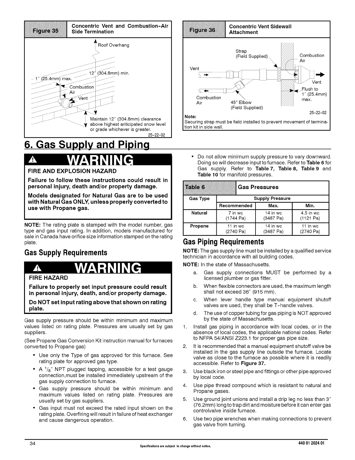
Biiiiiiiii:iiiii}iiii!i!iliiii_;iiiiiiDDDi_Ji!iiiiUiiiiii!_!i_iii!!_iiii_,ii'@i_,i!,iliii:i:i@
ii//liiiiiii/!i i! !i !i iiiiConcentricVentandCombuetion-Air
Side Termination
A RoofOverhang
l-y J:
_ 1" (25 4mm) m-_ia;x.......... 1-_ t i(30_i-_m )
..........g ..........:N :j_- Air ..............::............/
..... ; .......-'_( ...... i Maintain 12"
._f-J (304.8mm) clearance
..............-V above highest anticipated snow level
or grade whichever is greater.
25-22-02
_lgurQ_; ; Concentric Vent Sidewall
Attachment
Air
(Field Supplied) 25-22-02
Note:
Securing strap must be field installed to prevent movement of termina-
tion kit in side wall.
6. Gas Supply and Piping
FIRE AND EXPLOSION HAZARD
Failure to follow these instructions could result in
personal injury, death and/or property damage.
Models designated for Natural Gas are to be used
with Natural Gas ON L¥, unless properly converted to
use with Propane gas.
NOTE: The rating plate is stamped with the model number, gas
type and gas input rating. In addition, models manufactured for
sale in Canada have orifice size information stamped on the rating
plate.
Gas Supply Requirements
Gas supply. Refer to Table7, Table 8,
Table 10 for manifold pressures.
QooPreooureo
{ [[[[[[[[[[[[[[[[[[[[[[[[[[
Do not allow minimum supply pressure to vary downward.
Doing so will decrease input to furnace. Refer to Table 6 for
Table 9 and
Gas Type Supply Pressure
Recommended Max. Min.
Natural 7 in wc 14 in wc 4.5 in wc
(1744 Pa) (3487 Pa) (1121 Pa)
Propane 11 in wc 14 in wc 11 in wc
(2740 Pa) (3487 Pa) (2740 Pa)
Gas Piping Requirements
NOTE: The gas supply line must be installed by a qualified service
technician in accordance with all building codes.
NOTE: In the state of Massachusetts.
FIRE HAZARD
Failure to properly set input pressure could result
in personal injury, death, and/or property damage.
Do NOT set input rating above that shown on rating
plate.
Gas supply pressure should be within minimum and maximum
values listed on rating plate. Pressures are usually set by gas
suppliers.
(See Propane Gas Conversion Kit instruction manual for furnaces
converted to Propane gas)
•Use only the Type of gas approved for this furnace. See
rating plate for approved gas type.
• A 1/8" NPT plugged tapping, accessible for a test gauge
connection,must be installed immediately upstream of the
gas supply connection to furnace.
• Gas supply pressure should be within minimum and
maximum values listed on rating plate. Pressures are
usually set by gas suppliers.
• Gas input must not exceed the rated input shown on the
rating plate. Overfiring will result in failure of heat exchanger
and cause dangerous operation.
1.
2.
3.
4.
5.
6.
a. Gas supply connections MUST be performed by a
licensed plumber or gas fitter.
b. When flexible connectors are used, the maximum length
shall not exceed 36" (915 mm).
c. When lever handle type manual equipment shutoff
valves are used, they shall be T-handle valves.
d. The use of copper tubing for gas piping is NOT approved
by the state of Massachusetts.
Install gas piping in accordance with local codes, or in the
absence of local codes, the applicable national codes. Refer
to NFPA 54/ANSI Z223.1 for proper gas pipe size.
It is recommended that a manual equipment shutoff valve be
installed in the gas supply line outside the furnace. Locate
valve as close to the furnace as possible where it is readily
accessible. Refer to Figure 37.
Use black iron or steel pipe and fittings or other pipe approved
by local code.
Use pipe thread compound which is resistant to natural and
Propane gases.
Use ground joint unions and install a drip leg no less than 3"
(76.2mm) long to trap dirt and moisture before it can enter gas
controlvalve inside furnace.
Use two pipe wrenches when making connections to prevent
gas valve from turning.
34 Specificationsare eubject to changewithout notice. 440 012024 01
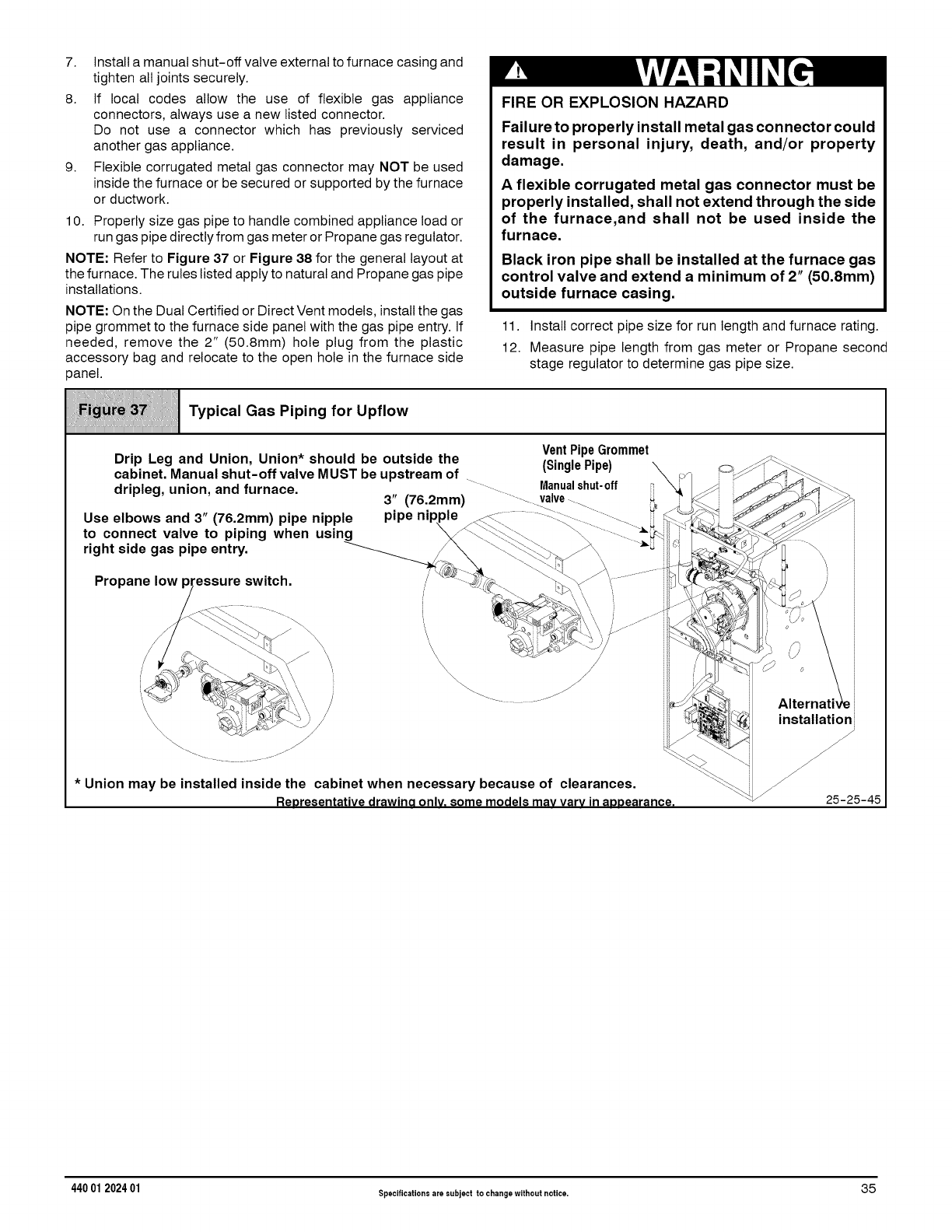
7. Install a manual shut-off valve external to furnace casing and
tighten all joints securely.
8. If local codes allow the use of flexible gas appliance
connectors, always use a new listed connector.
Do not use a connector which has previously serviced
another gas appliance.
9. Flexible corrugated metal gas connector may NOT be used
inside the furnace or be secured or supported by the furnace
or ductwork.
10. Properly size gas pipe to handle combined appliance load or
run gas pipe directly from gas meter or Propane gas regulator.
NOTE: Refer to Figure 37 or Figure 38 for the general layout at
the furnace. The rules listed apply to natural and Propane gas pipe
installations.
NOTE: On the Dual Certified or Direct Vent models, install the gas
pipe grommet to the furnace side panel with the gas pipe entry. If
needed, remove the 2" (50.8mm) hole plug from the plastic
accessory bag and relocate to the open hole in the furnace side
panel.
FIRE OR EXPLOSION HAZARD
Failure to properly install metal gas connector could
result in personal injury, death, and/or property
damage.
Aflexible corrugated metal gas connector must be
properly installed, shall not extend through the side
of the furnace,and shall not be used inside the
furnace.
Black iron pipe shall be installed at the furnace gas
control valve and extend a minimum of 2" (50.8mm)
outside furnace casing.
11. Install correct pipe size for run length and furnace rating.
12. Measure pipe length from gas meter or Propane second
stage regulator to determine gas pipe size.
:i i i i:
::__iil :ii_ Typical Gas Piping for Upflow
iiiiiiiiiiiiiiiiiiiiiiiiiiiiiiiiiiiiiiiiiiiiiiiiiiiiiiiiiiiiiiiiiiiiiiiiiiiiiiiiiiiiiiiiiiiiiiiiiiiiiiiiiiiiiiiiiiiiiiiiiiiiiiiiiiiiiiiiiiiiiiii
.Vent Pipe Grommet
Drip Leg and Union, Union should be outside the "Sin-le Pi-e_ \ __
cabinet. Manual shut-off valve MUST be upstream of -. (_vJ \ .. _'i_ i .i_
dripleg, union, and furnace. ,, "......... Manualshut-off iiX /_ ', _ ._ .........
3 (76.2mm) ...._. valve-... _ '_ _'_ _I _
•'-_ .... t; -_ _ _J ×_-_
" ................ Ienl le "..... _-.._ _" _ _
Use elbows and 3 (76.2mm) p,pe topple P P PP _ .<_.\.\ ...._ .... _ _'< _r_ _ _ i
to connect valve to piping when using \_\_\ _.\ _ ....... " _ _ _3 _'_ _
right side gas pipe entry. _ _ _)_)@_ ......._J "_" _ _ _ i
X -_; / -_ "_ installationi
* Union may be installed inside the cabinet when necessary because of clearances. \_
Reoresentative drawino only. some models mayvary in aooearance. \ 25-2/°_-°5-45
440 01 202401 Specificationsare subject to changewithout notice. 35
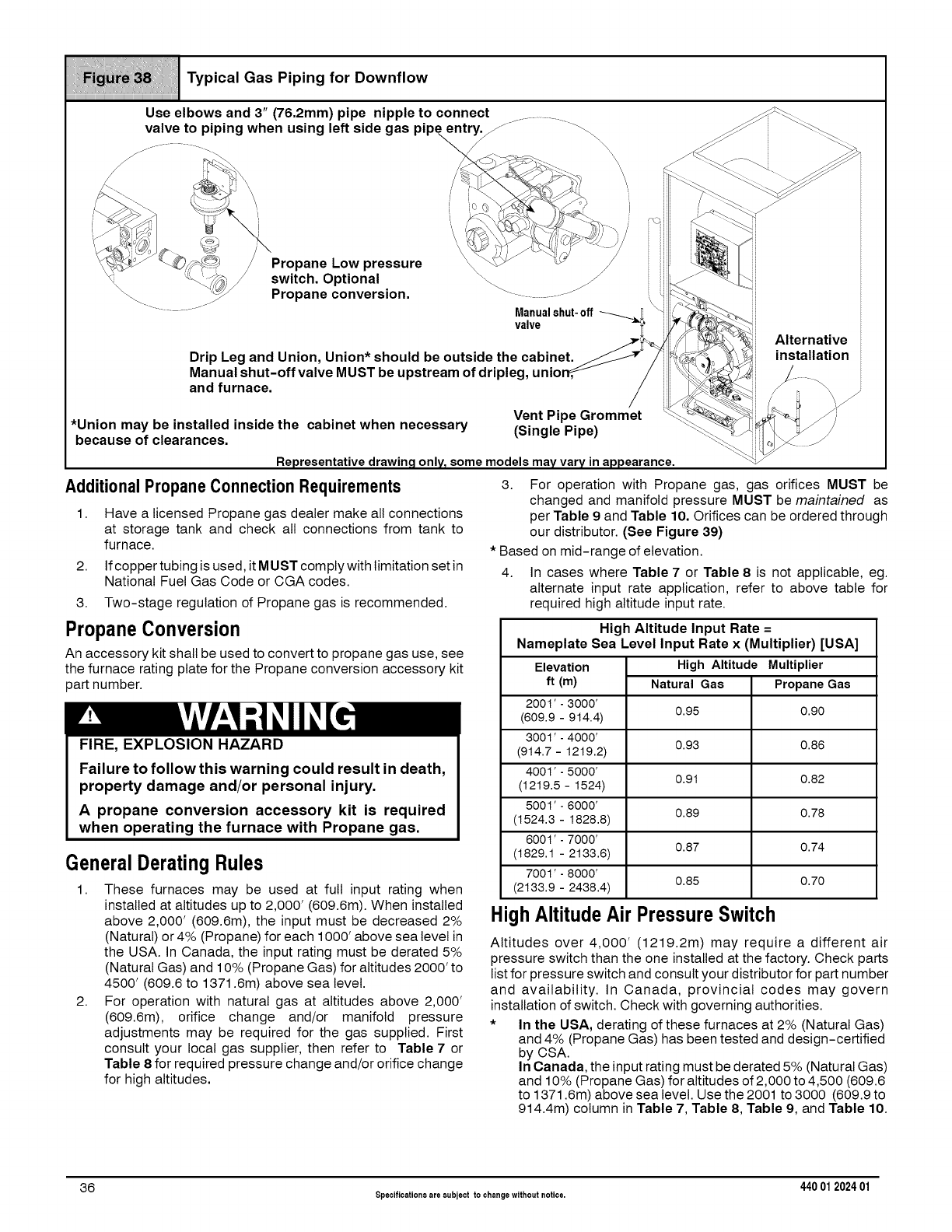
Use elbows and 3" (76.2mm) pipe nipple to connect .................. S_.
valve to piping when using left side gas pipe entry._ j _ ._s i _'_
__ _S_ /Propane Low pressure k_ _-cc.i /ii _l N
t "_/ switch. Optional _ _ _ i ,-_ _k_i _
_Propane conversion. _ ................. ,\ _ c_@ -i _
............ Manualshut-off "qi'
_ _7_ Alternative ii
* net _._ _ _ nstallation
Drip Leg and Union, Union should be outside the cabi .JJ /_4_ _.
Manual shut-off valve MUST be upstream of dripleg, unio_ /'_ _ /.....
and furnace, i _ _-°_
Vent Pipe Grommet "_'_'_ _
*Union may be installed inside the cabinet when necessary "Sin le Pi e" \_.-.._J- _\ w//
because of clearances. !. g P) \\_C il_ _j
Representative drawing only, some models mayvary in appearance. "q
Additional Propane Connection Requirements
1. Have a licensed Propane gas dealer make all connections
at storage tank and check all connections from tank to
furnace.
2. If copper tubing is used, it MUST comply with limitation set in
National Fuel Gas Code or CGA codes.
3. Two-stage regulation of Propane gas is recommended.
3. For operation with Propane gas, gas orifices MUST be
changed and manifold pressure MUST be maintained as
per Table 9 and Table 10. Orifices can be ordered through
our distributor. (See Figure 39)
*Based on mid-range of elevation.
4. In cases where Table 7 or Table 8 is not applicable, eg.
alternate input rate application, refer to above table for
required high altitude input rate.
PropaneConversion
An accessory kit shall be used to convert to propane gas use, see
the furnace rating plate for the Propane conversion accessory kit
part number.
FIRE, EXPLOSION HAZARD
Failure to followthis warning could result in death,
property damage and/or personal injury.
A propane conversion accessory kit is required
when operating the furnace with Propane gas.
GeneralDeratingRules
1. These furnaces may be used at full input rating when
installed at altitudes up to 2,000' (609.6m). When installed
above 2,000' (609.6m), the input must be decreased 2%
(Natural) or 4% (Propane) for each 1000' above sea level in
the USA. In Canada, the input rating must be derated 5%
(Natural Gas) and 10% (Propane Gas) for altitudes 2000' to
4500' (609.6 to 1371.6m) above sea level.
2. For operation with natural gas at altitudes above 2,000'
(609.6m), orifice change and/or manifold pressure
adjustments may be required for the gas supplied. First
consult your local gas supplier, then refer to Table 7 or
Table 8 for required pressure change and/or orifice change
for high altitudes.
High Altitude Input Rate =
Nameplate Sea Level Input Rate x (Multiplier) [USA]
High Altitude MultiplierElevation
ft (m)
2001' - 3000'
(609.9 - 914.4)
3001' - 4000'
(914.7 - 1219.2)
4001' - 5000'
(1219.5 - 1524)
5001' - 6000'
(1524.3- 1828.8)
6001' - 7000'
(1829.1 - 2133.6)
7001' - 8000'
(2133.9 - 2438.4)
Natural Gas Propane Gas
0.95 0.90
0.93 0.86
0.91 0.82
0.89 0.78
0.87 0.74
0.85 0.70
HighAltitudeAir PressureSwitch
Altitudes over 4,000' (1219.2m) may require a different air
pressure switch than the one installed at the factory. Check parts
list for pressure switch and consult your distributor for part number
and availability. In Canada, provincial codes may govern
installation of switch. Check with governing authorities.
* In the USA, derating of these furnaces at 2% (Natural Gas)
and 4% (Propane Gas) has been tested and design-certified
by CSA.
In Canada, the input rating must be derated 5% (Natural Gas)
and 10% (Propane Gas) for altitudes of 2,000 to 4,500 (609.6
to 1371.6m) above sea level. Use the 2001 to 3000 (609.9 to
914.4m) column in Table 7, Table 8, Table 9, and Table 10.
36 Specificationsare subject to changewithout notice. 440 012024 01
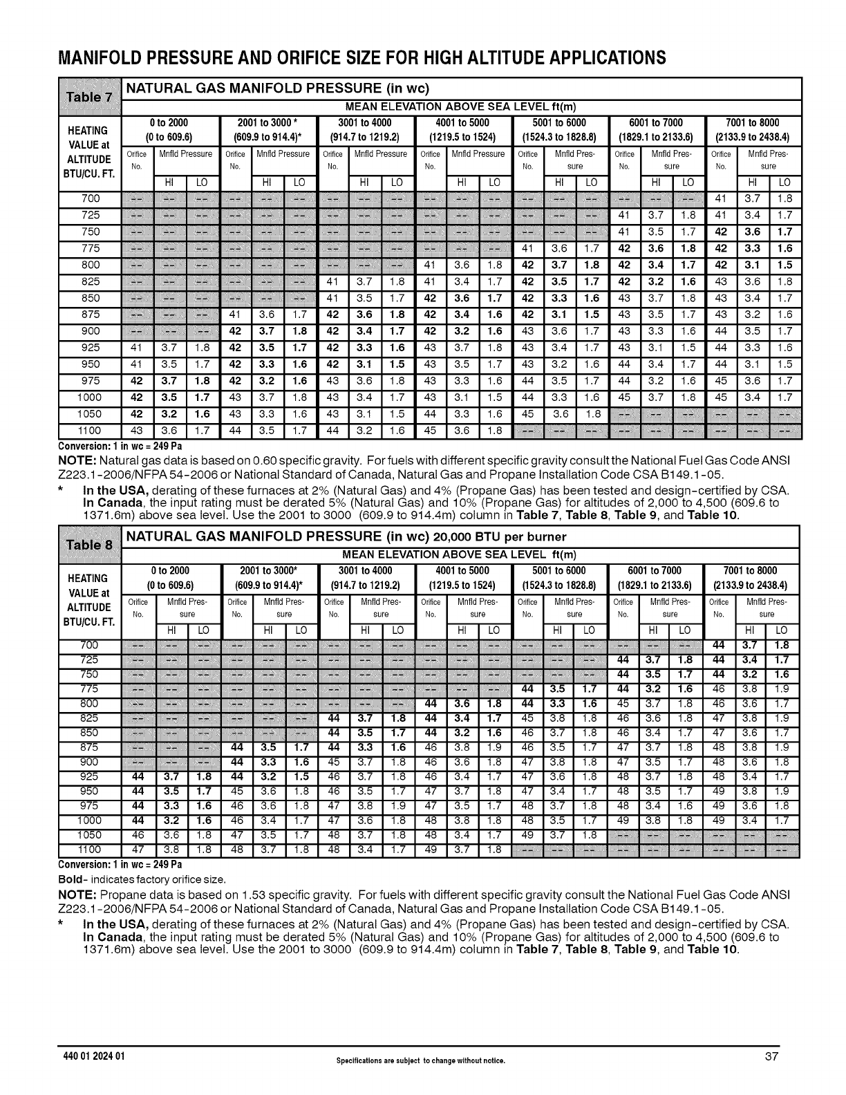
MANIFOLDPRESSUREAND ORIFICESIZE FORHIGHALTITUDEAPPLICATIONS
HEATING
VALUEat
ALTITUDE
BTU/CU.FT.
NATURAL GAS MANIFOLD PRESSURE (in wc)
MEAN ELEVATION ABOVE SEA LEVEL ft(m)
0to 2000 2001to 3000* 3001to 4000 4001to 5000 5001to 6000 6001to 7000 7001to 8000
(0to 609.6) (609.9to 914.4)* (914.7to 1219.2) (1219.5to 1524) (1524.3to 1828.8) (1829.1to 2133.6) (2133.9to 2438.4)
Orifice MnfldPressure Orifice MnfldPressure Orifice MnfldPressure Orifice MnfldPressure Orifice MnfldPres- Orifice MnfldPres- Orifice MnfldPres-
No. No. No. No. No. sure No. sure No. sure
HI LO HI LO HI LO HI LO HI LO HI LO HI LO
700 4t 3.7 1.8
725 ; _- . ,_ 4t 3.7 1.8 4t 3.4 1.7
750 4t 3.5 1.7 42 3,6 1,7
775 ............................................4t 3.6 1.7 42 3,6 1,8 42 3,3 1,6
800 _. _-' 4t 3.6 1.8 42 3,7 1,8 42 3,4 1,7 42 3,1 1,5
825 ,_ =,,_'_ =,'41 3.7 1.8 4t 3.4 1.7 42 3,5 1,7 42 3.2 1.6 43 3.6 1.8
850 :_=,,,_;.-_ 41 3.5 1.7 42 3,6 1,7 42 3,3 1,6 43 3.7 1.8 43 3.4 1.7
875 4t 3.6 1.7 42 3.6 1.8 42 3.4 1.6 42 3.1 1.5 43 3.5 1.7 43 3.2 1.6
900 42 3,7 1,8 42 3,4 1,7 42 3.2 1.6 43 3.6 1.7 43 3.3 1.6 44 3.5 1.7
925 4t 3.7 1.8 42 3,5 1,7 42 3,3 1.6 43 3.7 1.8 43 3.4 1.7 43 3.1 1.5 44 3.3 1.6
950 4t 3.5 1.7 42 3,3 1,6 42 3,1 1.5 43 3.5 1.7 43 3.2 1.6 44 3.4 1.7 44 3.1 1.5
975 42 3,7 1,8 42 3.2 1.6 43 3.6 1.8 43 3.3 1.6 44 3.5 1.7 44 3.2 1.6 45 3.6 1.7
1000 42 3,5 1,7 43 3.7 1.8 43 3.4 1.7 43 3.1 1.5 44 3.3 1.6 45 3.7 1.8 45 3.4 1.7
1050 42 3.2 1.6 43 3.3 1.6 43 3.1 1.5 44 3.3 1.6 45 3.6 1.8
1100 43 3.6 1.7 44 3.5 1.7 44 3.2 1.6 45 3.6 1.8
Conversion:1in wc=249Pa
NOTE: Natural gas data is based on 0.60 specific gravity. For fuels with different specific gravity consult the National Fuel Gas Code ANSI
Z223.1-2006/N FPA 54-2006 or National Standard of Canada, Natural Gas and Propane Installation Code CSA B 149.1-05.
*In the USA, derating of these furnaces at 2% (Natural Gas) and 4% (Propane Gas) has been tested and design-certified by CSA.
In Canada, the input rating must be derated 5% (Natural Gas) and 10% (Propane Gas) for altitudes of 2,000 to 4,500 (609.6 to
1371.6m) above sea level. Use the 2001 to 3000 (609.9 to 914.4m) column in Table 7, Table 8, Table 9, and Table 10.
NATURAL GAS MANIFOLD PRESSURE (in wc) 20,000 BTU per burner
MEAN ELEVATION ABOVE SEA LEVEL ft(m)
7001to 8000
(2133.9to 2438.4)
Orifice MnfldPres-
No. sure
0to 2000
HEATING (0to 609.6)
VALUEat Orifice MnfldPres-
ALTITUDE No. sure
BTU/CU.FT. HI LO
2001to 3000* 3001to 4000 4001to 5000 5001 to 6000 6001to 7000
(609.9to 914.4)* (914.7to 1219.2) (1219.5to 1524) (1524.3to 1828.8) (1829.1to 2133.6)
Orifice MnfldPres- Orifice MnfldPres- Orifice MnfldPres- Orifice MnfldPres- Orifice MnfldPres-
No. sure No. sure No. sure No. sure No. sure
HI LO HI LO HI LO HI LO HI LO HI LO
700 _, ,_,_ , ,_ 44 3.7 1.8
725 .......................................................................................................................................................................................................................................44 3.7 1.8 44 3.4 1.7
750 _'. _. _ . ._ 44 3,5 1,7 44 3,2 1,6
775 '; 44 3,5 1,7 44 3,2 1,6 46 3.8 1.9
800 # 44 3,6 1,8 44 3,3 1,6 45 3.7 1.8 46 3.6 1.7
825 44 3.7 1.8 44 3.4 1.7 45 3.8 1.8 46 3.6 1.8 47 3.8 1.9
850 44 3.5 1.7 44 3.2 1.6 46 3.7 1.8 46 3.4 1.7 47 3.6 1.7
875 44 3,5 1,7 44 3,3 1,6 46 3.8 1.9 46 3.5 1.7 47 3.7 1.8 48 3.8 1.9
900 44 3,3 1,6 45 3.7 1.8 46 3.6 1.8 47 3.8 1.8 47 3.5 1.7 48 3.6 1.8
925 44 3,7 1.8 44 3.2 1.5 46 3.7 1.8 46 3.4 1.7 47 3.6 1.8 48 3.7 1.8 48 3.4 1.7
950 44 3,5 1,7 45 3.6 1.8 46 3.5 1.7 47 3.7 1.8 47 3.4 1.7 48 3.5 1.7 49 3.8 1.9
975 44 3,3 1,6 46 3.6 1.8 47 3.8 1.9 47 3.5 1.7 48 3.7 1.8 48 3.4 1.6 49 3.6 1.8
1000 44 3.2 1.6 46 3.4 1.7 47 3.6 1.8 48 3.8 1.8 48 3.5 1.7 49 3.8 1.8 49 3.4 1.7
1050 46 3.6 1.8 47 3.5 1.7 48 3.7 1.8 48 3.4 1.7 49 3.7 1.8
1100 47 3.8 1.8 48 3.7 1.8 48 3.4 1.7 49 3.7 1.8
Conversion:1in wc=249Pa
Bold- indicates factory orifice size.
NOTE: Propane data is based on 1.53 specific gravity. For fuels with different specific gravity consult the National Fuel Gas Code ANSI
Z223.1-2006/N FPA 54-2006 or National Standard of Canada, Natural Gas and Propane Installation Code CSA B149.1-05.
* In the USA, derating of these furnaces at 2% (Natural Gas) and 4% (Propane Gas) has been tested and design-certified by CSA.
In Canada, the input rating must be derated 5% (Natural Gas) and 10% (Propane Gas) for altitudes of 2,000 to 4,500 (609.6 to
1371.6m) above sea level. Use the 2001 to 3000 (609.9 to 914.4m) column in Table 7, Table 8, Table 9, and Table 10.
440 01 202401 Specificationsare subject to changewithout notice. 37
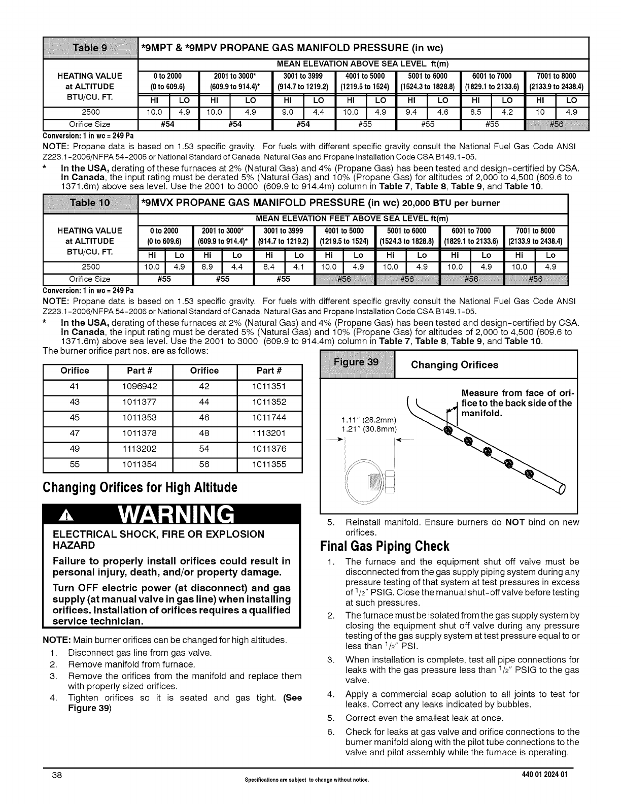
*9MPT &*9MPV PROPANE GAS MANIFOLD PRESSURE (in wc)
MEAN ELEVATIONABOVE SEA LEVEL ft(m)
HEATINGVALUE 0to 2000 2001to 3000* 3001to 3999 4001to 5000 5001to 6000 6001to 7000 7001to 8000
at ALTITUDE (0to609.6) (609.9to914.4)* (914.7to1219.2) (1219.5to 1524) (1524.3to 1828.8) (1829.1to2133.6) (2133.9to2438.4)
otu cu t "° .o ,1.o ,1.o ,1.o ,1.o ,1.o2500 10.0 4.9 10.0 4.9 9.0 4.4 10.0 4.9 9.4 4.6 8.5 4.2 10 4.9
Orifice Size #54 #54 #54 #55 #55 #55
Conversion:1inwc= 249Pa
NOTE: Propane data is based on 1.53 specific gravity. For fuels with different specific gravity consult the National Fuel Gas Code ANSI
Z223.1-2006/NFPA 54-2006 or National Standardof Canada, Natural Gas and Propane Installation CodeCSA B149.1-05.
* In the USA, derating of these furnaces at 2% (Natural Gas) and 4% (Propane Gas) has been tested and design-certified by CSA.
In Canada, the input rating must be derated 5% (Natural Gas) and 10% (Propane Gas) for altitudes of 2,000 to 4,500 (609.6 to
1371.6m) above sea level. Use the 2001 to 3000 (609.9 to 914.4m) column in Table 7, Table 8, Table 9, and Table 10.
*9MVX PROPANE GAS MANIFOLD PRESSURE (in wc)20,000 BTU per burner
MEAN ELEVATION FEET ABOVE SEA LEVEL ft(m)
HEATINGVALUE 0to2000 2001to3000* 3001to3999 4001to5000 5001to6000 6001to7000 7001to8000
at ALTITUDE (0to609.6) (609.9to914.4)* (914.7to 1219.2) (1219.5to1524) (1524.3to1828.8) (1829.1to2133.6) (2133.9to2438.4)
tu cu t .,I.o .11.o .11.o., .o .,I.o .,I.o .,I.o
2500 10.0 4.9 8.9 4.4 8.4 4.1 10.0 4.9 10.0 4.9 10.0 4.9 10.0 4.9
Orifice Size #55 #55 #55 I)N #56 #56 #56
Conversion:1inwc=249Pa
NOTE: Propane data is based on 1.53 specific gravity. For fuels with different specific gravity consult the National Fuel Gas Code ANSI
Z223.1-2006/NFPA 54-2006 or National Standardof Canada, Natural Gas and Propane Installation CodeCSA B149.1-05.
* In the USA, derating of these furnaces at 2% (Natural Gas) and 4% (Propane Gas) has been tested and design-certified by CSA.
In Canada, the input rating must be derated 5% (Natural Gas) and 10% (Propane Gas) for altitudes of 2,000 to 4,500 (609.6 to
1371.6m) above sea level. Use the 2001 to 3000 (609.9 to 914.4m) column in Table 7, Table 8, Table 9, and Table 10.
The burner orifice part nos. are as follows:
Orifice Part# Orifice Part#
41 1096942 42 1011351
43 1011377 44 1011352
45 1011353 46 1011744
47 1011378 48 1113201
49 1113202 54 1011376
55 1011354 56 1011355
ChangingOrificesfor HighAltitude
i_ii_ _i_i_ Changing Orifices
iiiiiiiiiiiiiiiiiiiiiiiiiiiiiiiiiiiiiiiiiiiiiiiiiiiiiiiiiiiiiiiiiiiiiiiiiiiiiiiiiiiiiiiiiiiiiiiiiiiiiiiiiiiiiiiiiiiiiiiiiiiiiiiiiiiiiiiiiiiiiiiiiiii
Measure from face of ori-
ELECTRICAL SHOCK, FIRE OR EXPLOSION
HAZARD
Failure to properly install orifices could result in
personal injury, death, and/or property damage.
Turn OFF electric power (at disconnect) and gas
supply (at manual valve in gas line) when installing
orifices. Installation of orifices requires a qualified
service technician.
NOTE: Main burner orifices can be changed for high altitudes.
1. Disconnect gas line from gas valve.
2. Remove manifold from furnace.
3. Remove the orifices from the manifold and replace them
with properly sized orifices.
4. Tighten orifices so it is seated and gas tight. (See
Figure 39)
5. Reinstall manifold. Ensure burners do NOT bind on new
orifices.
Final Gas PipingCheck
1. The furnace and the equipment shut off valve must be
disconnected from the gas supply piping system during any
pressure testing of that system at test pressures in excess
of 1/2" PSIG. Close the manual shut-offvalve before testing
at such pressures.
2. The furnace must be isolated from the gas supply system by
closing the equipment shut off valve during any pressure
testing of the gas supply system at test pressure equal to or
less than 1/2" PSI.
3. When installation is complete, test all pipe connections for
leaks with the gas pressure less than 1/2" PSIG to the gas
valve.
4. Apply a commercial soap solution to all joints to test for
leaks. Correct any leaks indicated by bubbles.
5. Correct even the smallest leak at once.
6. Check for leaks at gas valve and orifice connections to the
burner manifold along with the pilot tube connections to the
valve and pilot assembly while the furnace is operating.
38 Specificationsare subject to changewithout notice. 440 012024 01
FIRE OR EXPLOSION HAZARD
Failure to follow this warning could result in
personal injury, death and/or property damage.
Never test for gas leaks with an open flame. Use a
commercially available soap solution made
specifically for the detection of leaks to check all
connections. A fire or explosion could result
causing property damage, personal injury and/or
loss of life.
7. Electrical Wiring
ELECTRICAL SHOCK HAZARD
Failure to turn off power could result in personal
injury or death.
Turn OFF electrical power at fuse box or service
panel before making any electrical connections
and ensure a proper ground connection is made
before connecting line voltage.
PowerSupply Wiring
The furnace MUST be electrically wired and grounded in
accordance with local codes, or inthe absence of local codes with
the latest edition of The National Electric Code, ANSI NFPA 70
and/or The Canadian Electric Code CSA C22.1.
Field wiring connections must be made inside the furnace
connection box. A suitable strain relief should be used at the point
the wires exit the furnace casing.
NOTE: Furnace will not have normal operation is line polarity is
reversed. Check ALL field and control connections prior to
operation.
Copper conductors shall be used. Line voltage wires should
conform to temperature limitation of 35 ° C rise and be sized for the
unit maximum amps stated on the rating plate. Add the full load
amps for potential field-installed accessories such as electronic
air cleaners and humidifiers that would receive power from the
furnace control board. The furnace control board is rated for a
maximum of 1.0 amps combined for EAC and HUM. Consult NEC
or local codes for proper wire and circuit sizing.
JunctionBox (J-Box) Relocation
The J-Box is installed on left side of casing. An alternate J-Box
location on right side can be used.
1. Remove bag containing two hole plugs and two self tapping
screws from loose parts bag in blower compartment.
2.
3.
Remove two screws holding J-Box to casing.
Install large hole plug from loose furnace accessory bag into
the left J-Box location.
4. Clip wire tie holding J-Box wires.
5. Move J-Box to alternate location and attach using two self
tapping screws from bag.
6. Apply two hole plugs from bag at left J-Box location.
RISQUE D'INDENDIE OU D'EXPLOSION
Le non-respect des avertissements de securite
pourrait d'entrainer des blessures graves, la mort
ou des dommages materiels.
Ne jamais utiliser une flamme nue por verifier la
presence des fuites de gaz. Pour la verification de
tous les joints, utiliser plut6t une solution
savonneuse commerciale fabriquee
specifiquement pur la detection des fuites de gaz.
Un incendie ou une explosion peut entrainer des
dommages materiels, des blessures ou la mort.
Thermostat
Heating
The two-stage furnace control board will operate with either a
single stage or a two-stage heating thermostat and will provide
two-stage heating operation.
For single-stage thermostat installations, the R and W wires from
the thermostat connect to the R and Wl connections on the
furnace control board. (See Figure 40 and wiring diagram)
Note: The TT (Thermostat Type) SW1 DIP switch #3 should be in
the OFF position for the furnace to operate properly with a
single-stage thermostat. Failure to change DIP switch with
single-stage thermostat will result in Low Heat operation ONLY.
During operation, the furnace will operate on Low Heat for up to12
minutes. If the heat request exists for more than 12 minutes, the
furnace will automatically shift to the High Heat mode for the
remaining duration of the heating cycle.
For two-stage thermostat installations, the R, Wl and W2 wires
from the thermostat connect to the R, Wl and W2 connections on
the furnace control board. Set TT SWl DIP switch #3 to ON
position. During operation, the furnace will shift from Low Heat to
High Heat as requested by the thermostat. (See Figure 40 and
wiring diagram)
Heat anticipator setting will need to be measured if 24VAC
humidifier is installed. Measure current in series from R to Wl at
the thermostat. Be sure 24VAC humidifier is operating during this
check. Allow furnace to operate for 2 minutes before recording the
AC amperage reading. Set anticipator on thermostat to recorded
value.
Thermostat location has an important effect on the operation of the
furnace. Follow instructions included with thermostat for correct
mounting and wiring.
Low voltage connections to furnace must be made on terminal
board to furnace control board. (See Figure 41)
Cooling
*9MPT
If cooling is used, the Y and G from the thermostat must be
connected to the control board Y/Y2 and G to energize cooling
blower speed.
NOTE: MPT models are not two-stage cooling compatible.
*9MPV,*9MVX
If single-speed cooling is used, the Y and G from the thermostat
must be connected to the control board Y/Y2 and G to energize
cooling blower speed.
440 01 202401 Specifications are subject to changewithout notice. 39
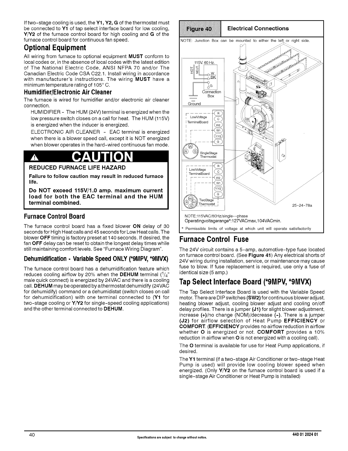
If two-stage cooling is used, the Y1, Y2, G of the thermostat must
be connected to Y1 of tap select interface board for low cooling,
Y/Y2 of the furnace control board for high cooling and G of the
furnace control board for continuous fan speed.
OptionalEquipment
All wiring from furnace to optional equipment MUST conform to
local codes or, in the absence of local codes with the latest edition
of The National Electric Code, ANSI NFPA 70 and/or The
Canadian Electric Code CSA C22.1. Install wiring in accordance
with manufacturer's instructions. The wiring MUST have a
minimum temperature rating of 105 ° C.
Humidifier/ElectronicAir Cleaner
The furnace is wired for humidifier and/or electronic air cleaner
connection.
HUMIDIFIER - The HUM (24V) terminal is energized when the
low pressure switch closes on a call for heat. The HUM (115V)
is energized when the inducer is energized.
ELECTRONIC AIR CLEANER - EAC terminal is energized
when there is a blower speed call, except it is NOT energized
when blower operates in the hard-wired continuous fan mode.
REDUCED FURNACELIFEHAZARD
Failure to follow caution may result in reduced furnace
life.
Do NOT exceed 115V/1.O amp. maximum current
load for both the EAC terminal and the HUM
terminal combined.
Furnace Control Board
The furnace control board has a fixed blower ON delay of 30
seconds for High Heat calls and 45 seconds for Low Heat calls. The
blower OFF timing is factory preset at 140 seconds. If desired, the
fan OFF delay can be reset to obtain the longest delay times while
still maintaining comfort levels. See "Furnace Wiring Diagram".
Dehumidification- VariableSpeedONLY(*gMPV,*gMVX)
The furnace control board has a dehumidification feature which
reduces cooling airflow by 20% when the DEHUM terminal (1/4"
male quick connect) is energized by 24VAC and there is a cooling
call. DEHUM may be operated by athermostat dehumidify (24VAC
for dehumidify) command or a dehumidistat (switch closes on call
for dehumidification) with one terminal connected to (Y1 for
two-stage cooling or Y/Y2 for single-speed cooling applications)
and the other terminal connected to DEHUM.
Electrical Connections
iiiiiiiiiiiiiiiiiiiiiiiiiiiiiiiiiiiiiiiiiiiiiiiiiiiiiiiiiiiiiiiiiiiiiiiiiiiiiiiiiiiiiiiiiiiiiiiiiiiiiiiiiiiiiiiiiiiiiiiiiiiiiiiiiiiiiiiiiiiiiiii
NOTE: Junction Box can be mounted to either the left or right side,
115V. 60 Hz,
==0o,Bn ot,on
G_ound
LowVottage (_
TerminalBoard
I[ -
I @
ingleStage
Thermostat
LowVoltage (_
TerminaIBoard
I......
F.... _Z)
oStage
ermosta_
\"-\-. ii
_ 25-24-78a
NOTE:l15VAC/60Hz/single--phase
Operatingvoltagerange:127VACmax,104VACmin.
* Permissible limits of voltage at which unit will operate satisfactorily
FurnaceControl Fuse
The 24V circuit contains a 5-amp, automotive-type fuse located
on furnace control board. (See Figure 41) Any electrical shorts of
24V wiring during installation, service, or maintenance may cause
fuse to blow. If fuse replacement is required, use only a fuse of
identical size (5 amp.)
Tap SelectInterfaceBoard (*9MPV,*9MVX)
The Tap Select Interface Board is used with the Variable Speed
motor. There are DIP switches (SW2) for continuous blower adjust,
heating blower adjust, cooling blower adjust and cooling on/off
delay profiles. There is a jumper (,.11)for slight blower adjustment,
increase (+)/no change (NOM)/decrease (-). There is a jumper
(J2) for airflow selection of Heat Pump EFFICIENCY or
COMFORT. (EFFICIENCY provides no airflow reduction in airflow
whether O is energized or not. COMFORT provides a 10%
reduction in airflow when O is not energized with a cooling call).
The O terminal is available for use for Heat Pump applications, if
desired.
The Y1 terminal (if a two-stage Air Conditioner or two-stage Heat
Pump is used) will provide low cooling blower speed when
energized. (Only Y/Y2 on the furnace control board is used if a
single-stage Air Conditioner or Heat Pump is installed)
40 Specificationsare subject to changewithout notice. 440 012024 01
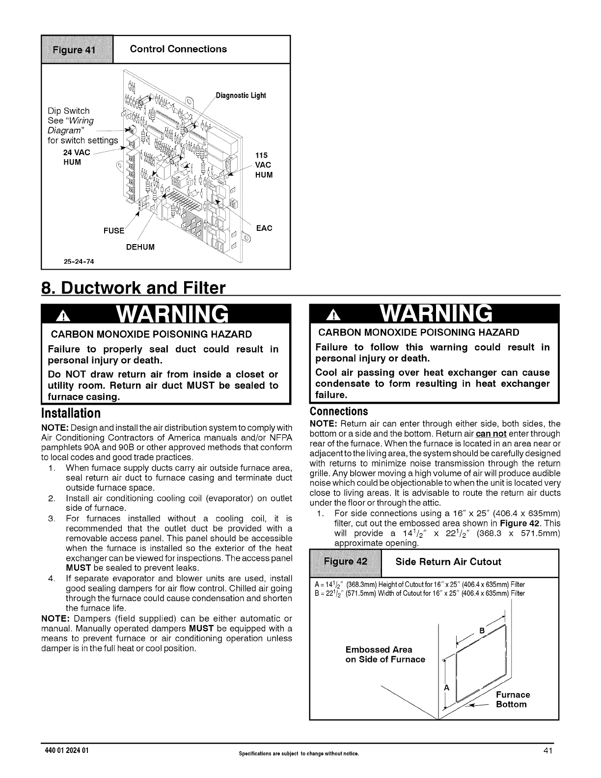
iiiiii!iiiiiii ! iiiiiiiiiiiiiHHi iiii
iiiiiiiiiiiiiiiiiiiiiiiiiiiiiiiiiiiiiiiiiiiiiiiiiiiiiiiiiiiiiiiiiiiiiiiiiiiiiiiiiiiiiiiiiiiiiiiiiiiiiiiiiiiiiiiiiiiiiiiiiiiiiiiiiiiiiiiiiiiiiiii
Se e "Winng _ _"_'_ I
• ' _ ._. r_%J_
Diagram" ............._ _? _
for switch settings i__!_
HUM (_-_'__
FUSE// "-_
DEHUM
25-24-74
Control Connections
_DiagnosticLight
/
\_ .<
8. Ductwork and Filter
115
VAC
HUM
EAC
CARBON MONOXIDE POISONING HAZARD
Failure to properly seal duct could result in
personal injury or death.
Do NOT draw return air from inside a closet or
utility room. Return air duct MUST be sealed to
furnace casing.
Installation
NOTE: Design and installthe air distribution system to comply with
Air Conditioning Contractors of America manuals and/or NFPA
pamphlets 90A and 90B or other approved methods that conform
to local codes and good trade practices.
1. When furnace supply ducts carry air outside furnace area,
seal return air duct to furnace casing and terminate duct
outside furnace space.
2. Install air conditioning cooling coil (evaporator) on outlet
side of furnace.
3. For furnaces installed without a cooling coil, it is
recommended that the outlet duct be provided with a
removable access panel. This panel should be accessible
when the furnace is installed so the exterior of the heat
exchanger can be viewed for inspections. The access panel
MUST be sealed to prevent leaks.
4. If separate evaporator and blower units are used, install
good sealing dampers for air flow control. Chilled air going
through the furnace could cause condensation and shorten
the furnace life.
NOTE: Dampers (field supplied) can be either automatic or
manual. Manually operated dampers MUST be equipped with a
means to prevent furnace or air conditioning operation unless
damper is in the full heat or cool position.
CARBON MONOXIDE POISONING HAZARD
Failure to follow this warning could result in
personal injury or death.
Cool air passing over heat exchanger can cause
condensate to form resulting in heat exchanger
failure.
Connections
NOTE: Return air can enter through either side, both sides, the
bottom or a side and the bottom. Return air can not enter through
rear of the furnace. When the furnace is located in an area near or
adjacent to the living area, the system should be carefully designed
with returns to minimize noise transmission through the return
grille. Any blower moving a high volume of air will produce audible
noise which could be objectionable to when the unit is located very
close to living areas. It is advisable to route the return air ducts
under the floor or through the attic.
1. For side connections using a 16" x 25" (406.4 x 635mm)
filter, cut out the embossed area shown in Figure 42. This
will provide a 141/2,' x 221/2,' (368.3 x 571.5mm)
approximate opening.
Side Return Air Cutout
iiiiiiiiiiiiiiiiiiiiiiiiiiiiiiiiiiiiiiiiiiiiiiiiiiiiiiiiiiiiiiiiiiiiiiiiiiiiiiiiiiiiiiiiiiiiiiiiiiiiiiiiiiiiiiiiiiiiiiiiiiiiiiiiiiiiiiiiiiiiiiii
A=141/2"(368.3mm)HeightofCutoutfor16"x25"(406.4x635mm)Filter
B=221/2''(571,5ram)WidthofCutoutfor16"x25"(406,4x635mm)Filter
Embossed Area _//_B.-/_
on Side of Furnace lJ __"
_._//_// Furnace
_Bottom
440 01 202401 Specificationsare subject to changewithout notice• 41
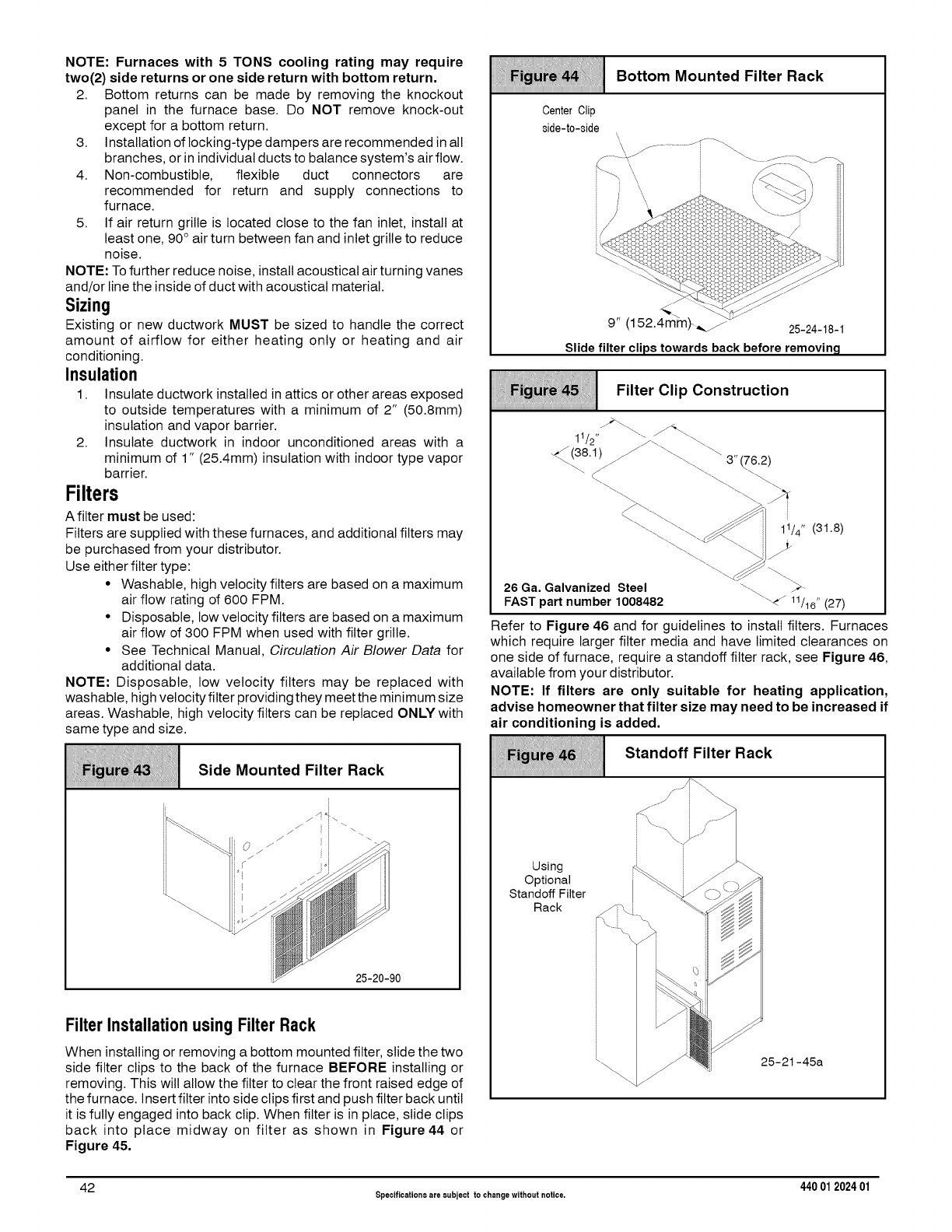
NOTE: Furnaces with 5 TONS cooling rating may require
two(2) side returns or one side return with bottom return.
2. Bottom returns can be made by removing the knockout
panel in the furnace base. Do NOT remove knock-out
except for a bottom return.
3. Installation of locking-type dampers are recommended in alt
branches, or in individual ducts to balance system's airflow.
4. Non-combustible, flexible duct connectors are
recommended for return and supply connections to
furnace.
5. If air return grille is located close to the fan inlet, install at
least one, 90° air turn between fan and inlet grille to reduce
noise.
NOTE: To further reduce noise, install acoustical air turning vanes
and/or line the inside of duct with acoustical material.
Sizing
Existing or new ductwork MUST be sized to handle the correct
amount of airflow for either heating only or heating and air
conditioning.
Insulation
1. Insulate ductwork installed in attics or other areas exposed
to outside temperatures with a minimum of 2" (50.8mm)
insulation and vapor barrier.
2. Insulate ductwork in indoor unconditioned areas with a
minimum of 1" (25.4mm) insulation with indoor type vapor
barrier.
Filters
A filter must be used:
Filters are supplied with these furnaces, and additional filters may
be purchased from your distributor.
Use either filter type:
• Washable, high velocity filters are based on a maximum
air flow rating of 600 FPM.
• Disposable, low velocity filters are based on a maximum
air flow of 300 FPM when used with filter grille.
• See Technical Manual, Circulation Air Blower Data for
additional data.
NOTE: Disposable, low velocity filters may be replaced with
washable, high velocity filter providing they meet the minimum size
areas. Washable, high velocity filters can be replaced ONLY with
same type and size.
i
__i Side Mounted Filter Rack
iiiiiiiiiiiiiiiiiiiiiiiiiiiiiiiiiiiiiiiiiiiiiiiiiiiiiiiiiiiiiiiiiiiiiiiiiiiiiiiiiiiiiiiiiiiiiiiiiiiiiiiiiiiiiiiiiiiiiiiiiiiiiiiiiiiiiiiiiiiiiiii
i i
25-20-90
Filter Installationusing Filter Rack
When installing or removing a bottom mounted filter, slide the two
side filter clips to the back of the furnace BEFORE installing or
removing. This will allow the filter to clear the front raised edge of
the furnace. Insert filter into side clips first and push filter back until
it is fully engaged into back clip. When filter is in place, slide clips
back into place midway on filter as shown in Figure 44 or
Figure 45,
Center Clip
side-to-side
Bottom Mounted Filter Rack
9" (152.4m _ 25-24-18-1
Slide filter clips towards back before removin_l
Filter Clip Construction
1/2 F\\\ \-\\_. 3" 6.2/
"\ \.\ _ 1]/4 '' (31.8)
26 Ga. Galvanized Steel \-\ >-
FAST part number 1008482 _\4/ 11/16"(27)
Refer to Figure 46 and for guidelines to install filters. Furnaces
which require larger filter media and have limited clearances on
one side of furnace, require a standoff filter rack, see Figure 46,
available from your distributor.
NOTE: If filters are only suitable for heating application,
advise homeowner that filter size may need to be increased if
air conditioning is added,
Standoff Filter Rack
Using
Optional
Standoff Filter
Rack
J
25-21-45a
42 Specificationsare subject to changewithout notice. 440 012024 01
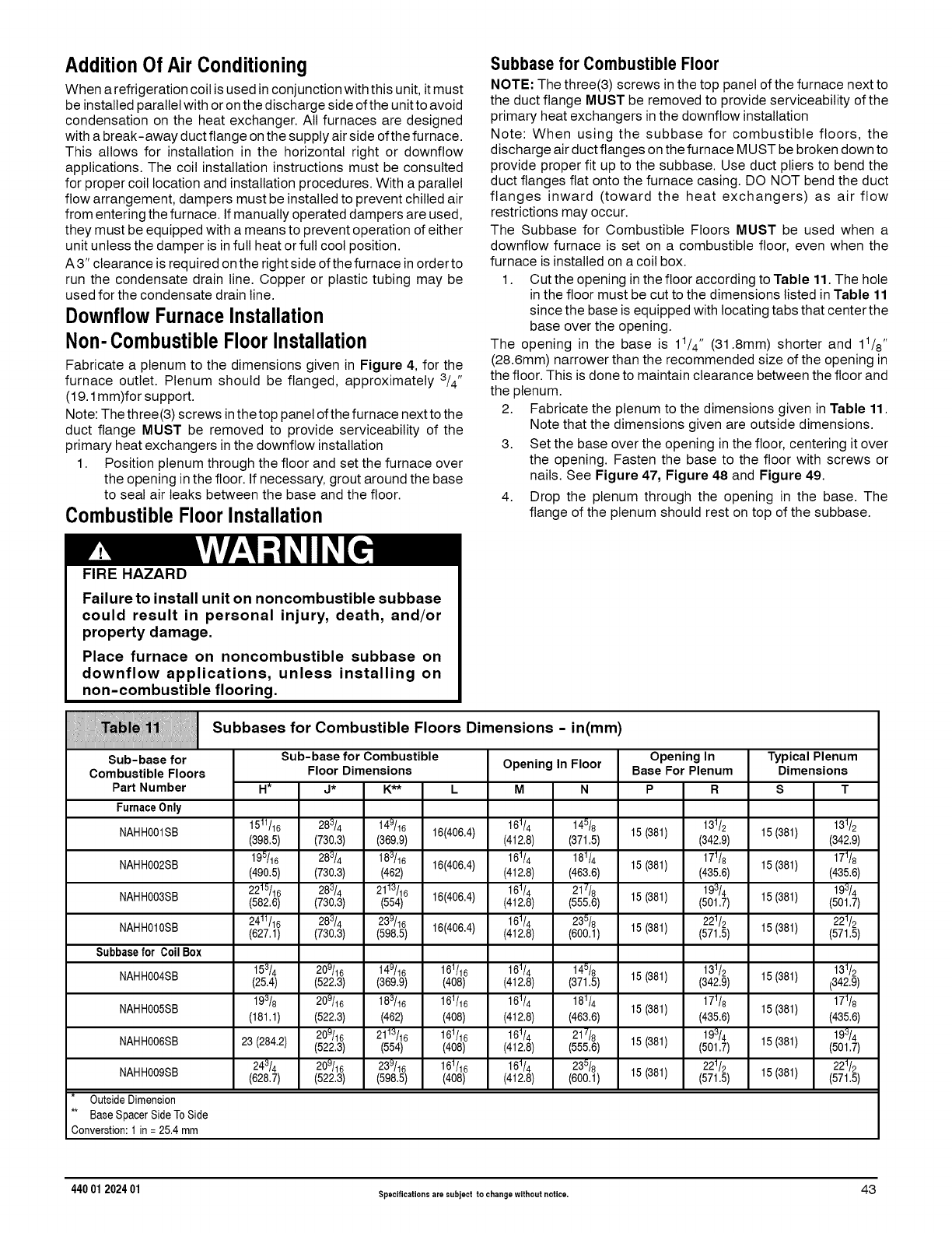
AdditionOf Air Conditioning
When a refrigeration coil is used in conjunction with this unit, it must
be installed parallel with or on the discharge side ofthe unit to avoid
condensation on the heat exchanger. All furnaces are designed
with a break-away duct flange on the supply air side ofthe furnace.
This allows for installation in the horizontal right or downflow
applications. The coil installation instructions must be consulted
for proper coil location and installation procedures. With a parallel
flow arrangement, dampers must be installed to prevent chilled air
from entering the furnace. If manually operated dampers are used,
they must be equipped with a means to prevent operation of either
unit unless the damper is in full heat or full cool position.
A 3" clearance is required on the right side of the furnace in order to
run the condensate drain line. Copper or plastic tubing may be
used for the condensate drain line.
DownflowFurnaceInstallation
Non-Combustible FloorInstallation
Fabricate a plenum to the dimensions given in Figure 4, for the
furnace outlet. Plenum should be flanged, approximately 3/4"
(19.1 mm)for support.
Note: The three(3) screws in the top panel ofthe furnace next to the
duct flange MUST be removed to provide serviceability of the
primary heat exchangers in the downflow installation
1. Position plenum through the floor and set the furnace over
the opening in the floor. If necessary, grout around the base
to seal air leaks between the base and the floor.
CombustibleFloor Installation
FIRE HAZARD
Subbase for CombustibleFloor
NOTE: The three(3) screws in the top panel of the furnace next to
the duct flange MUST be removed to provide serviceability of the
primary heat exchangers in the downfiow installation
Note: When using the subbase for combustible floors, the
discharge air duct flanges on the furnace MUST be broken down to
provide proper fit up to the subbase. Use duct pliers to bend the
duct flanges flat onto the furnace casing. DO NOT bend the duct
flanges inward (toward the heat exchangers) as air flow
restrictions may occur.
The Subbase for Combustible Floors MUST be used when a
downflow furnace is set on a combustible floor, even when the
furnace is installed on a coil box.
1. Cut the opening in the floor according to Table 11. The hole
in the floor must be cut to the dimensions listed in Table 11
since the base is equipped with locating tabs that center the
base over the opening.
The opening in the base is 11/4 '' (31.8mm) shorter and 11/8,'
(28.6mm) narrower than the recommended size of the opening in
the floor. This is done to maintain clearance between the floor and
the plenum.
2. Fabricate the plenum to the dimensions given in Table 11.
Note that the dimensions given are outside dimensions.
3. Set the base over the opening in the floor, centering it over
the opening. Fasten the base to the floor with screws or
nails. See Figure 47, Figure 48 and Figure 49.
4. Drop the plenum through the opening in the base. The
flange of the plenum should rest on top of the subbase.
Failure to install unit on noncombustible subbase
could result in personal injury, death, and/or
property damage.
Place furnace on noncombustible subbase on
downflow applications, unless installing on
non-combustible flooring.
illiiii!!! ii!i
iiiiiiiiiiiiiiiiiiiiiiiiiiiiiiiiiiiiiiiiiiiiiiiiiiiiiiiiiiiiiiiiiiiiiiiiiiiiiiiiiiiiiiiiiiiiiiiiiiiiiiiiiiiiiiiiiiiiiiiiiiiiiiiiiiiiiiiiiiiiiiiiiiiiiiiiiiiiiiiiiiiiiiii
Sub-base for
Combustible Floors
Part Number
FurnaceOnly
NAHH001SB
NAHH002SB
NAHH003SB
NAHHOIOSB
Subbasefor CoilBox
NAHHOO4SB
NAHH005SB
NAHH006SB
Subbases for Combustible Floors Dimensions -in(mm)
H*
Sub-base for Combustible
Floor Dimensions Opening In Floor
J* K** L M N
Opening In Typical Plenum
Base For Plenum Dimensions
P R S T
1511/16 283/4 149/16 16(406,4) 161/4 145/8 15 (381) 131/2 15 (381) 131/2
(398,5) (730,3) (369,9) (412,8) (371,5) (342,9) (342,9)
195/16 283/4 183/16 16(406,4) 161/4 181/4 15 (381) 171/8 15 (381) 171/8
(490,5) (730,3) (462) (412,8) (463,6) (435,6) (435,6)
2215/16 283/4 2113/16 161/4 217/8 15 (381) 193/4 15 (381) 193/4
(582,6) (730,3) (554) 16(406,4) (412,8) (555,6) (501,7) (501,7)
2411/16 283/4 239/16 16(406,4) 161/4 235/8 15 (381) 221/2 15 (381) 221/2
(627,1) (730,3) (598,5) (412,8) (600,1) (571,5) (571,5)
153/4 209/16 149/16 161/16 161/4 145/8 15 (381) 131/2 15 (381) 131/2
(25,4) (522,3) (369,9) (408) (412,8) (371,5) (342,9) (342,9)
193/8 209/16 183/16 161/16 161/4 181/4 171/8 171/8
(181,1) (522,3) (462) (408) (412,8) (463,6) 15 (381) (435,6) 15 (381) (435,6)
209/16 2113/16 161/16 161/4 217/8 15 (381) 193/4 15 (381) 193/4
23 (284,2) (522,3) (554) (408) (412,8) (555,6) (501,7) (501,7)
243/4 209/16 239/16 161/16 161/4 235/8 15 (381) 221/2 15 (381) 221/2
NAHH009SB (628,7) (522,3) (598,5) (408) (412,8) (600,1) (571,5) (571,5)
Outside Dimension
** Base Spacer Side To Side
Converstion: 1 in = 25,4 mm
440 01 2024 01 specificationsaresubjecttochangewithoutnotice. 43
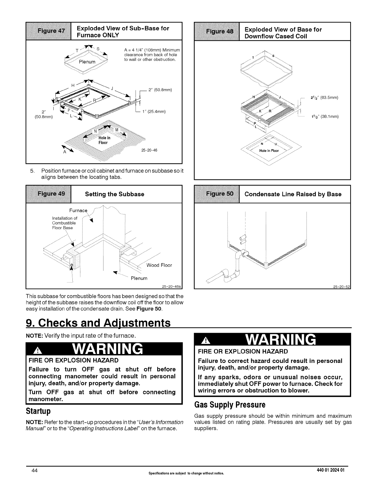
iiiiiii_iiiiiiiiii!iiT_7iiiiiiii!iiiiiiiiiiiiii_iiiiiiiiiiii!!ifiiiiiiT_¸i_iiH!iiiiiiiii)i;iiiiii!iiiiiiiiii{ijiiiiiiii!;ii{{iiT_iiiiil;
Exploded View of Sub-Base for
Furnace ONLY
..,_r\
T _._]_S
_-_Plenum _
A = 4 1/4" (108mm) Minimum
clearance from back of hole
to wall or other obstruction,
Iv[-
5. Position furnace or coil cabinet and furnace on subbase so it
aligns between the locating tabs.
iiiiiii_!iMi_i1i!iii_`_`_`iiiiii!!!H_iiiiiii!!_iii_iiii_ii!ii_i1iii`_iiiii!iIiiJii:`i_ii11i_!_!!!!7ii_i1iii1i_i_7iiii_i!_
Exploded View of Base for
Downflow Cased Coil
_.'<\ Holeln Floor_
21/2" (63.5mm)
11/2"(38.1mm)
Setting the Subbase
iiiiiiiiiiiiiiiiiiiiiiiiiiiiiiiiiiiiiiiiiiiiiiiiiiiiiiiiiiiiiiiiiiiiiiiiiiiiiiiiiiiiiiiiiiiiiiiiiiiiiiiiiiiiiiiiiiiiiiiiiiiiiiiiiiiiiiiiiiiiiiii
Furnace\iF-_\_ "_-_
nstaatonof /" _:_ i
Combustible • ::
Floor Base iI
"_! :i \-_W_ Wood Floor
! "_-.L \t
...... Plenum
25-20-46a
iiiiiiiliiiiiiliiiiiiiiiiiiiiijiiiiiiiiiii:iiiiiiiiiiii{iiii1;iiiii ii!iiiiiriiiil :
:; ii__!i:i Condensate Line Raised by Base
iiiiiiiiiiiiiiiiiiiiiiiiiiiiiiiiiiiiiiiiiiiiiiiiiiiiiiiiiiiiiiiiiiiiiiiiiiiiiiiiiiiiiiiiiiiiiiiiiiiiiiiiiiiiiiiiiiiiiiiiiiiiiiiiiiiiiiiiiiiiiiii
25-20-52
This subbase for combustible floors has been designed so that the
height of the subbase raises the downflow coil off the floor to allow
easy installation of the condensate drain. See Figure 50.
9. Checks and Adjustments
NOTE: Verify the input rate of the furnace.
FIRE OR EXPLOSION HAZARD
Failure to turn OFF gas at shut off before
connecting manometer could result in personal
injury, death, and/or property damage.
Turn OFF gas at shut off before connecting
manometer.
Startup
NOTE: Referto the start-up proceduresinthe "User's Information
Manual" orto the "Operating InstructionsLabel" onthe furnace.
FIRE OR EXPLOSION HAZARD
Failure to correct hazard could result in personal
injury, death, and/or property damage.
If any sparks, odors or unusual noises occur,
immediately shut OFF power to furnace. Check for
wiring errors or obstruction to blower.
Gas Supply Pressure
Gas supply pressure should be within minimum and maximum
values listed on rating plate. Pressures are usually set by gas
suppliers.
44 Specifications are subject to changewithout notice. 440 012024 01
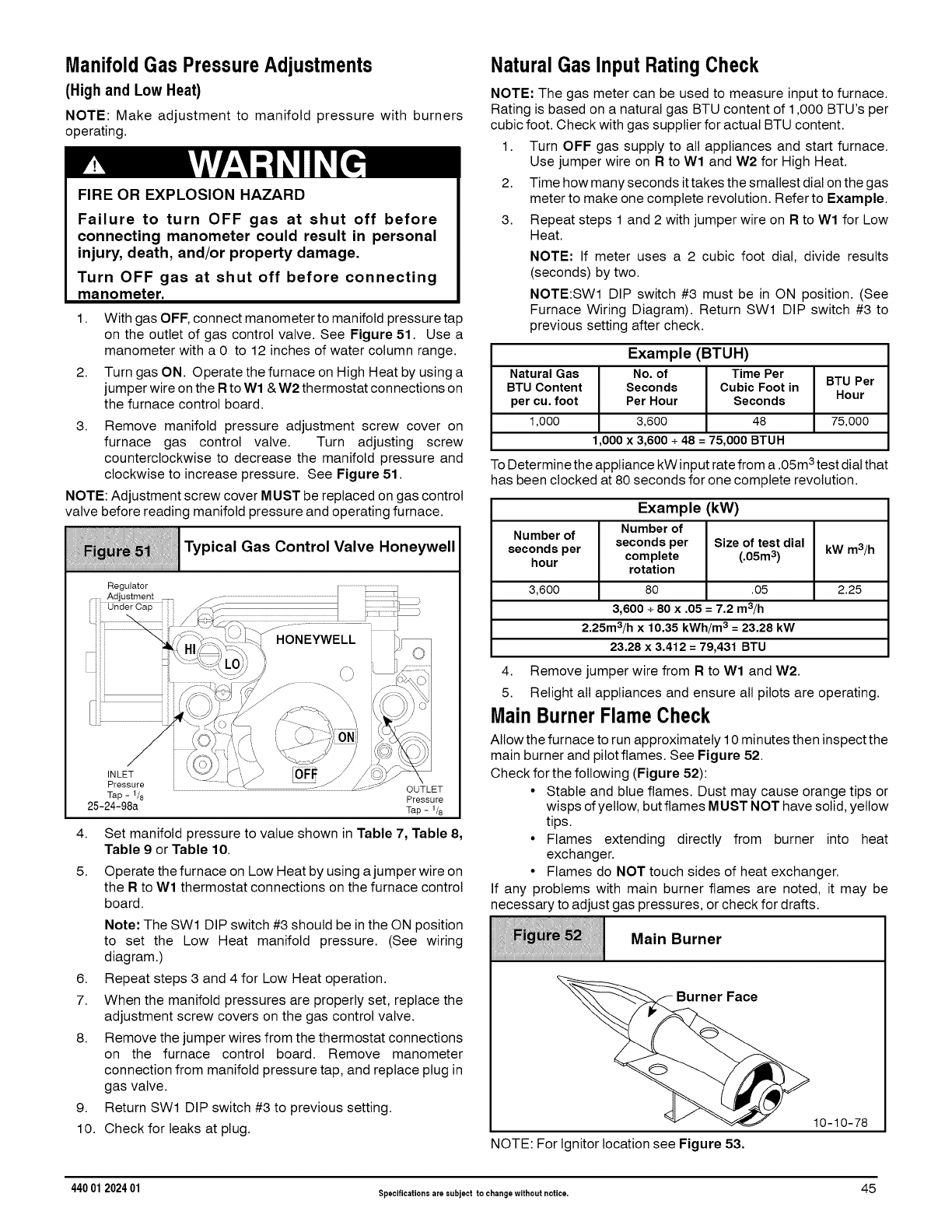
ManifoldGas PressureAdjustments
(High and Low Heat)
NOTE: Make adjustment to manifold pressure with burners
operating.
FIRE OR EXPLOSION HAZARD
Failure to turn OFF gas at shut off before
connecting manometer could result in personal
injury, death, and/or property damage.
Turn OFF gas at shut off before connecting
manometer.
1. With gas OFF, connect manometer to manifold pressure tap
on the outlet of gas control valve. See Figure 51. Use a
manometer with a 0 to 12 inches of water column range.
2. Turn gas ON. Operate the furnace on High Heat by using a
jumper wire on the Rto Wl & W2 thermostat connections on
the furnace control board.
3. Remove manifold pressure adjustment screw cover on
furnace gas control valve. Turn adjusting screw
counterclockwise to decrease the manifold pressure and
clockwise to increase pressure. See Figure 51.
NOTE: Adjustment screw cover MUST be replaced on gas control
valve before reading manifold pressure and operating furnace.
iiii
:!i__ii!i !i!:i Typical Gas Control Valve Honeywell
Regulator
OUTLET
Tap - 1/8 Pressure
25-24-98a Tap- 1/8
4. Set manifold pressure to value shown in Table 7, Table 8,
Table 9 or Table 10.
5. Operate the furnace on Low Heat by using a jumper wire on
the R to Wl thermostat connections on the furnace control
board.
Note: The SWl DIP switch #3 should be in the ON position
to set the Low Heat manifold pressure. (See wiring
diagram.)
6. Repeat steps 3 and 4 for Low Heat operation.
7. When the manifold pressures are properly set, replace the
adjustment screw covers on the gas control valve.
8. Remove the jumper wires from the thermostat connections
on the furnace control board. Remove manometer
connection from manifold pressure tap, and replace plug in
gas valve.
9. Return SWl DIP switch #3 to previous setting.
10. Check for leaks at plug.
NaturalGas InputRatingCheck
NOTE: The gas meter can be used to measure input to furnace.
Rating is based on a natural gas BTU content of 1,000 BTU's per
cubic foot. Check with gas supplier for actual BTU content.
1. Turn OFF gas supply to all appliances and start furnace.
Use jumper wire on R to Wl and W2 for High Heat.
2. Time how many seconds ittakes the smallest dial on the gas
meter to make one complete revolution. Refer to Example.
3. Repeat steps 1 and 2 with jumper wire on R to Wl for Low
Heat.
NOTE: If meter uses a 2 cubic foot dial, divide results
(seconds) by two.
NOTE:SWl DIP switch #3 must be in ON position. (See
Furnace Wiring Diagram). Return SWl DIP switch #3 to
previous setting after check.
Example (BTUH)
Natural Gas No. of Time Per BTU Per
BTU Content Seconds Cubic Foot in
per cu, foot Per Hour Seconds Hour
1,000 3,600 48 75,000
1,000 x 3,600 +48 = 75,000 BTUH
To Determine the appliance 3
kW input rate from a .05m test dial that
has been clocked at 80 seconds for one complete revolution.
Example (kW)
Number of
Number of
seconds per seconds per Size of test dial kW m3/h
hour complete (.05m 3)
rotation
3,600 80 .05 2.25
3,600 + 80 x ,05 = 7,2 m3/h
2,25m3/h x 10,35 kWh/m 3= 23,28 kW
23.28 x 3.412 = 79,431 BTU
4. Remove jumper wire from R to Wl and W2.
5. Relight all appliances and ensure all pilots are operating.
Main BurnerFlameCheck
Allow the furnace to run approximately 10 minutes then inspect the
main burner and pilot flames. See Figure 52.
Check for the following (Figure 52):
•Stable and blue flames. Dust may cause orange tips or
wisps of yellow, but flames MUST NOT have solid, yellow
tips.
• Flames extending directly from burner into heat
exchanger.
• Flames do NOT touch sides of heat exchanger.
If any problems with main burner flames are noted, it may be
necessary to adjust gas pressures, or check for drafts.
Main Burner
iiiiiiiiiiiiiiiiiiiiiiiiiiiiiiiiiiiiiiiiiiiiiiiiiiiiiiiiiiiiiiiiiiiiiiiiiiiiiiiiiiiiiiiiiiiiiiiiiiiiiiiiiiiiiiiiiiiiiiiiiiiiiiiiiiiiiiiiiiiiiiii
NOTE: For Ignitor location see Figure 53.
10-10-78
440 01 202401 Specificationsare subject to changewithout notice. 45
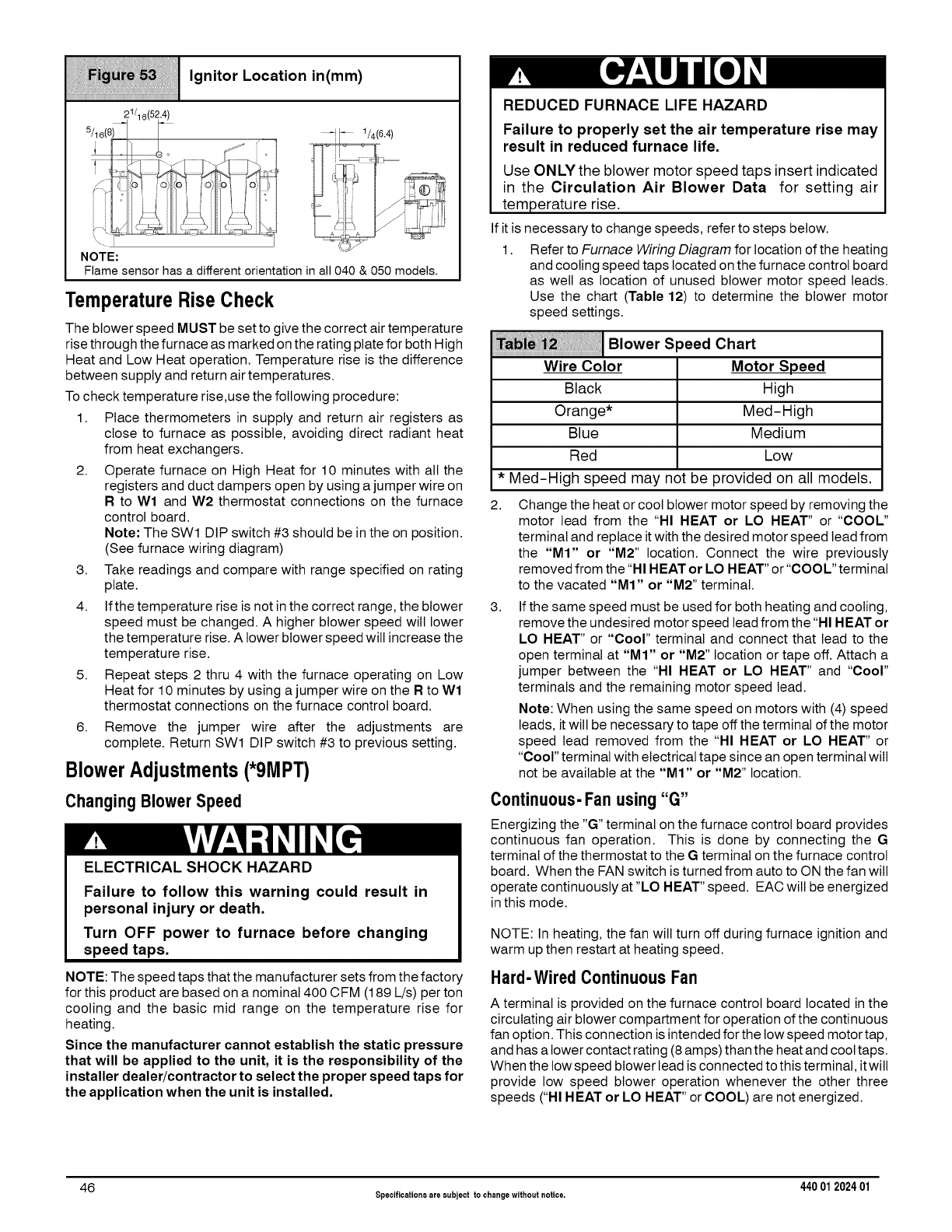
Ignitor Location in(mm)
iiiiiiiiiiiiiiiiiiiiiiiiiiiiiiiiiiiiiiiiiiiiiiiiiiiiiiiiiiiiiiiiiiiiiiiiiiiiiiiiiiiiiiiiiiiiiiiiiiiiiiiiiiiiiiiiiiiiiiiiiiiiiiiiiiiiiiiiiiiiiiii
21/16(52.4)
5/, 6(8_ _ ............ -; .
:ii il l/
NOTE:
Flame sensor has a different orientation in all 040 & 050 model&
TemperatureRiseCheck
The blower speed MUST be set to give the correct air temperature
rise through the furnace as marked on the rating plate for both High
Heat and Low Heat operation. Temperature rise is the difference
between supply and return air temperatures.
To check temperature rise,use the following procedure:
1. Place thermometers in supply and return air registers as
close to furnace as possible, avoiding direct radiant heat
from heat exchangers.
2. Operate furnace on High Heat for 10 minutes with all the
registers and duct dampers open by using a jumper wire on
R to Wl and W2 thermostat connections on the furnace
control board.
Note: The SWl DIP switch #3 should be in the on position.
(See furnace wiring diagram)
3. Take readings and compare with range specified on rating
plate.
4. Ifthe temperature rise is not in the correct range, the blower
speed must be changed. A higher blower speed will lower
the temperature rise. A lower blower speed will increase the
temperature rise.
5. Repeat steps 2 thru 4 with the furnace operating on Low
Heat for 10 minutes by using a jumper wire on the R to Wl
thermostat connections on the furnace control board.
6. Remove the jumper wire after the adjustments are
complete. Return SWl DIP switch #3 to previous setting.
BlowerAdjustments(*9MPT)
Changing Blower Speed
ELECTRICAL SHOCK HAZARD
Failure to follow this warning could result in
personal injury or death.
Turn OFF power to furnace before changing
speed taps.
NOTE: The speed taps that the manufacturer sets from the factory
for this product are based on a nominal 400 CFM (189 L/s) per ton
cooling and the basic mid range on the temperature rise for
heating.
Since the manufacturer cannot establish the static pressure
that will be applied to the unit, it is the responsibility of the
installer dealer/contractor to select the proper speed taps for
the application when the unit is installed,
REDUCED FURNACELIFEHAZARD
Failure to properly set the air temperature rise may
result in reduced furnace life,
Use ON LY the blower motor speed taps insert indicated
in the Circulation Air Blower Data for setting air
temperature rise.
If it is necessary to change speeds, refer to steps below.
1. Refer to Furnace Wiring Diagram for location of the heating
and cooling speed taps located on the furnace control board
as well as location of unused blower motor speed leads.
Use the chart (Table 12) to determine the blower motor
speed settings.
!!i!!i !ili
Wire Color
Black
Orange*
Blue
Red
Blower Speed Chart
Motor Speed
High
Med-High
Medium
Low
* Med-High speed may not be provided on all models.
2.
3.
Change the heat or cool blower motor speed by removing the
motor lead from the "HI HEAT or LO HEAT" or "COOL"
terminal and replace it with the desired motor speed lead from
the "MI" or "M2" location. Connect the wire previously
removed from the "HI HEAT or LO HEAT" or "COOL" terminal
to the vacated "MI" or "M2" terminal.
If the same speed must be used for both heating and cooling,
remove the undesired motor speed lead from the "HI HEAT or
LO HEAT" or "Cool" terminal and connect that lead to the
open terminal at "MI" or "M2" location or tape off. Attach a
jumper between the "HI HEAT or LO HEAT" and "coor'
terminals and the remaining motor speed lead.
Note: When using the same speed on motors with (4) speed
leads, it will be necessary to tape off the terminal of the motor
speed lead removed from the "HI HEAT or LO HEAT" or
"coor' terminal with electrical tape since an open terminal will
not be available at the "M1" or "M2" location.
Continuous-Fan using"G"
Energizing the "G" terminal on the furnace control board provides
continuous fan operation. This is done by connecting the G
terminal of the thermostat to the Gterminal on the furnace control
board. When the FAN switch is turned from auto to ON the fan will
operate continuously at "LO HEAT" speed. EAC wilt be energized
in this mode.
NOTE: In heating, the fan will turn off during furnace ignition and
warm up then restart at heating speed.
Hard-Wired Continuous Fan
A terminal is provided on the furnace control board located in the
circulating air blower compartment for operation of the continuous
fan option. This connection is intended for the low speed motor tap,
and has a lower contact rating (8amps) than the heat and cool taps.
When the low speed blower lead is connected to this terminal, it will
provide low speed blower operation whenever the other three
speeds ("HI HEAT or LO HEAT" or COOL) are not energized.
46 Specificationsare subject to changewithout notice. 440 012024 01
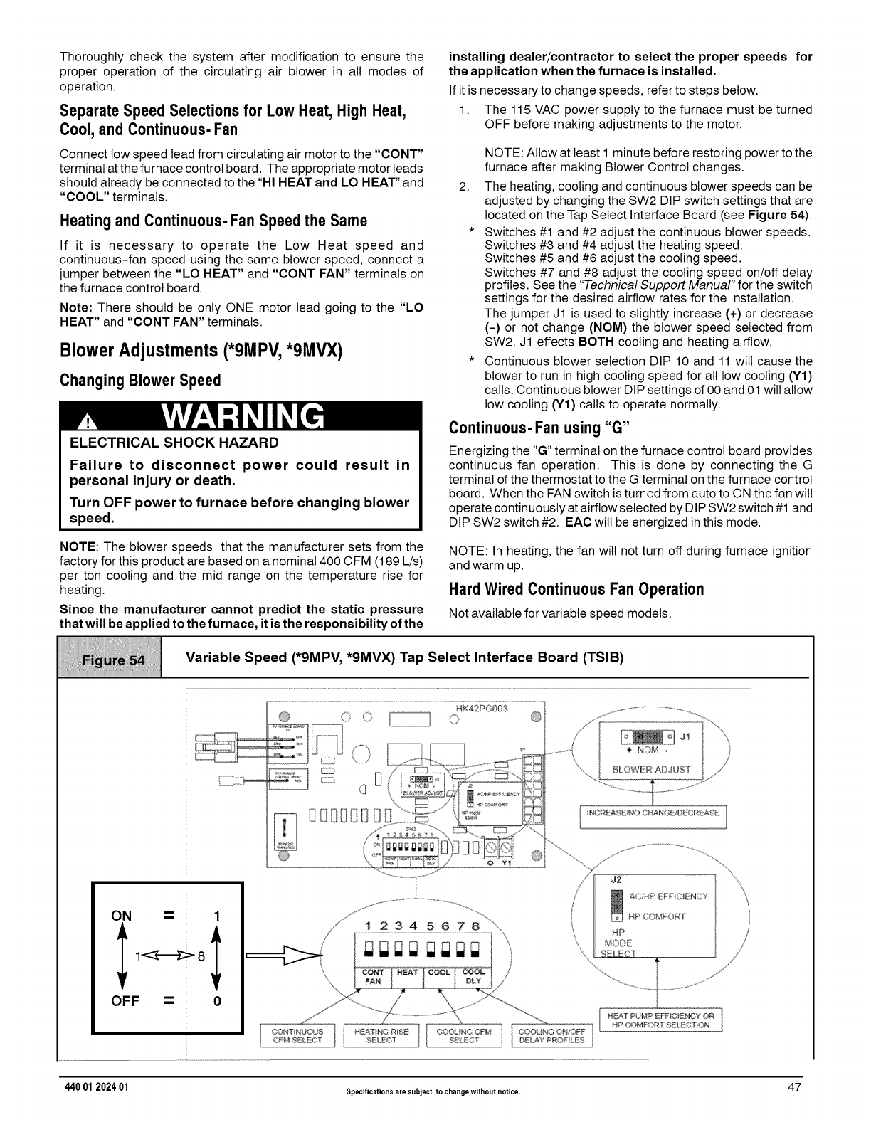
Thoroughly check the system after modification to ensure the
proper operation of the circulating air blower in all modes of
operation.
Separate Speed Selections for Low Heat,High Heat,
Cool, and Continuous-Fan
Connect low speed lead from circulating air motor to the "CONT"
terminal at the furnace control board. The appropriate motor leads
should already be connected to the "HI HEAT and LO HEAT" and
"COOL" terminals.
Heating and Continuous-Fan Speedthe Same
If it is necessary to operate the Low Heat speed and
continuous-fan speed using the same blower speed, connect a
jumper between the "LO HEAT" and "CONT FAN" terminals on
the furnace control board.
Note: There should be only ONE motor lead going to the "LO
HEAT" and "CONT FAN" terminals.
Blower Adjustments (*9MPV, *9MVX)
ChangingBlowerSpeed
ELECTRICAL SHOCK HAZARD
Failure to disconnect power could result in
personal injury or death.
Turn OFF power to furnace before changing blower
speed.
NOTE: The blower speeds that the manufacturer sets from the
factory for this product are based on a nominal 400 CFM (189 L/s)
per ton cooling and the mid range on the temperature rise for
heating.
Since the manufacturer cannot predict the static pressure
that will be applied to the furnace, it is the responsibility of the
installing dealer/contractor to select the proper speeds for
the application when the furnace is installed.
If it is necessary to change speeds, refer to steps below.
1. The 115 VAC power supply to the furnace must be turned
OFF before making adjustments to the motor.
2.
NOTE: Allow at least 1 minute before restoring power to the
furnace after making Blower Control changes.
The heating, cooling and continuous blower speeds can be
adjusted by changing the SW2 DIP switch settings that are
located on the Tap Select Interface Board (see Figure 54).
* Switches #1 and #2 adjust the continuous blower speeds.
Switches #3 and #4 adjust the heating speed.
Switches #5 and #6 adjust the cooling speed.
Switches #7 and #8 adjust the cooling speed on/off delay
profiles. See the "Technical Support Manual" for the switch
settings for the desired airflow rates for the installation.
The jumper J1 is used to slightly increase (+) or decrease
(-) or not change (NOM) the blower speed selected from
SW2. J1 effects BOTH cooling and heating airflow.
* Continuous blower selection DIP 10 and 11 will cause the
blower to run in high cooling speed for all low cooling (Y1)
calls. Continuous blower DIP settings of 00 and 01 will allow
low cooling (Y1) calls to operate normally.
Continuous-Fan using"G"
Energizing the "G" terminal on the furnace control board provides
continuous fan operation. This is done by connecting the G
terminal of the thermostat to the G terminal on the furnace control
board. When the FAN switch is turned from auto to ON the fan will
operate continuously at airflow selected by DIP SW2 switch #1 and
DIP SW2 switch #2. EAC will be energized in this mode.
NOTE: In heating, the fan will not turn off during furnace ignition
and warm up.
Hard Wired Continuous Fan Operation
Not available for variable speed models.
Variable Speed (*9MPV, *9MVX) Tap Select Interface Board (TSIB)
HK42PG003
( O O O
_SDI]iEtSD8_
J1
+NOM -
BLOWER ADJUST
ON ---- 1
I
OFF -- 0
440 01 202401 Specificationsare subject to changewithout notice. 47
10. Furnace Maintenance
FIRE, EXPLOSION, OR CARBON MONOXIDE
HAZARDS
Failure to have the furnace inspected and
maintained could result in personal injury, death,
and/or property damage,
It is recommended that the furnace be inspected
and serviced on an annual basis (before the heating
season) by a qualified service technician.
See "User's Information Manual".
ELECTRICAL SHOCK, FIRE OR EXPLOSION
HAZARD
Failure to follow this warning could result in
personal injury, death, and/or property damage.
• Before servicing, disconnect all electrical
power to furnace.
•When servicing controls, label all wires prior to
disconnecting. Reconnect wires correctly.
•Verify proper operation after servicing.
See "User's Information Manual" and the "Service Manual".
48 Specifications are subject to changewithout notice. 440 012024 01
11. Sequence of Operation & Diagnostics (*9MPT)
The following is the normal operating sequence at factory default settings (SWl OFF/ON/OFF)
Cooling(Y) Request:
24VAC signals applied to Y/Y2 & G terminals of FCB (furnace control board).
• Cool motor speed is energized after 5 second Cool Fan On Delay time.
Y/Y2 & G signals removed from FOB
• Cool motor speed is de-energized after 90 second Cool Fan Off Delay time.
NOTE: DEHUM not available on the *9MPT models.
ContinuousCirculatingFan(G) Request:
24VAC signal applied to G terminal of FCB.
• Low-Heat motor speed is energized without delay.
G signal removed from FOB.
• Low-Heat motor speed is de-energized after 5 second delay.
NOTE 1) Furnace de-energizes the fan during the heat exchanger warm-up period on a call for Heating that occurs during a G request
unless a blower motor lead is connected to the CONT FAN terminal on the FOB, in which case see NOTE 2)
NOTE 2) Heating or Cooling requests received during a Fan request cause the fan speed to change to the appropriate heat or cool speed
after the Fan On Delay time expires. The fan returns to continuous circulating speed after the selected Fan Off Delaytime expires following
loss of the Heating or Cooling request.
ContinuousCirculatingFanHard-Wired (Cont)Request:
Field selected low speed motor tap installed on "CONT FAN" terminal.
• Low speed is energized when power applied to furnace. Operates at this speed continuously while there are no other
blower demands from furnace control board. Fan demands from furnace control board for heat, cool or"G" will override hard-wired
speed tap.
NOTE 3) EAC is NOT active for hard-wired mode but IS active for fan demands from furnace control board for heat, cool and "G".
Heating(Wl) Request(singlestagethermostatoperation,SW1 DIP switch#3 mustbe in OFF
position) (see furnace wiring diagram):
24VAC signal applied to W1 terminal of FCB.
• Inducer motor turns on at high speed.
• Following a 15 second prepurge delay after the low pressure switch closes, the ignitor begins a 17 second warm up.
• The gas valve is energized, the main burners light at Low Heat rate and flame is sensed.
• The ignitor is de-energized, and the inducer drops to low speed after the main burners ignite.
• The FOB will delay Low Heat blower operation for the 45-second Low Heat Fan On Delay time, timed from
the opening of the gas valve.
• If the Wl request is still present after 12 minutes, timed from the opening of the gas valve, the inducer switches to high speed,
closing the high pressure switch, then the High Heat solenoid energizes, and the fan switches to High Heat speed.
W1 signal removed from FOB.
• The gas valve de-energizes and the main burners go out.
• The inducer runs at its present speed for a 15 second postpurge period.
• The fan runs at its present speed.
• The fan de-energizes after the selected Heat Fan Off Delay time expires, timed from the gas valve de-energizing.
NOTE 4) If a new Heating request arrives while the control is waiting in the Heat Fan Off Delay time, the FOB wilt wait for the selected H eat
Fan Off Delay then start a new heating cycle as long as the heat call remains.
Heating Request(Wl l W2) (two-stage thermostatoperation,SW1 DIP switch#3 mustbe in ON
position)(see furnacewiringdiagram):
24VAC signal applied to Wl terminal of FCB.
• Same response as single stage thermostat operation (fan uses Low Stage Heat On Delay) described above except the control
will not go to High Heat rate, and High Heat Fan speed unless a W2 signal is applied.
24VAC signal applied to Wl and W2 terminals of FOB.
• Same light-off routine as described for the signal stage thermostat operation except main burners light at High Heat rate, the
inducer remains on high speed after ignition, and the FOB wilt delay blower operation at the High Heat Fan speed for 30 second
On Delay time.
NOTE 5) The FOB responds without delay to the presence or loss of W2 (with W1 constant). W1 & W2 result in high inducer, High Heat
rate, and High Heat Fan speed. Wl only results in low inducer, Low Heat rate, and Low Heat Fan speed.
440 01 202401 Specificationsare subject to changewithout notice. 49
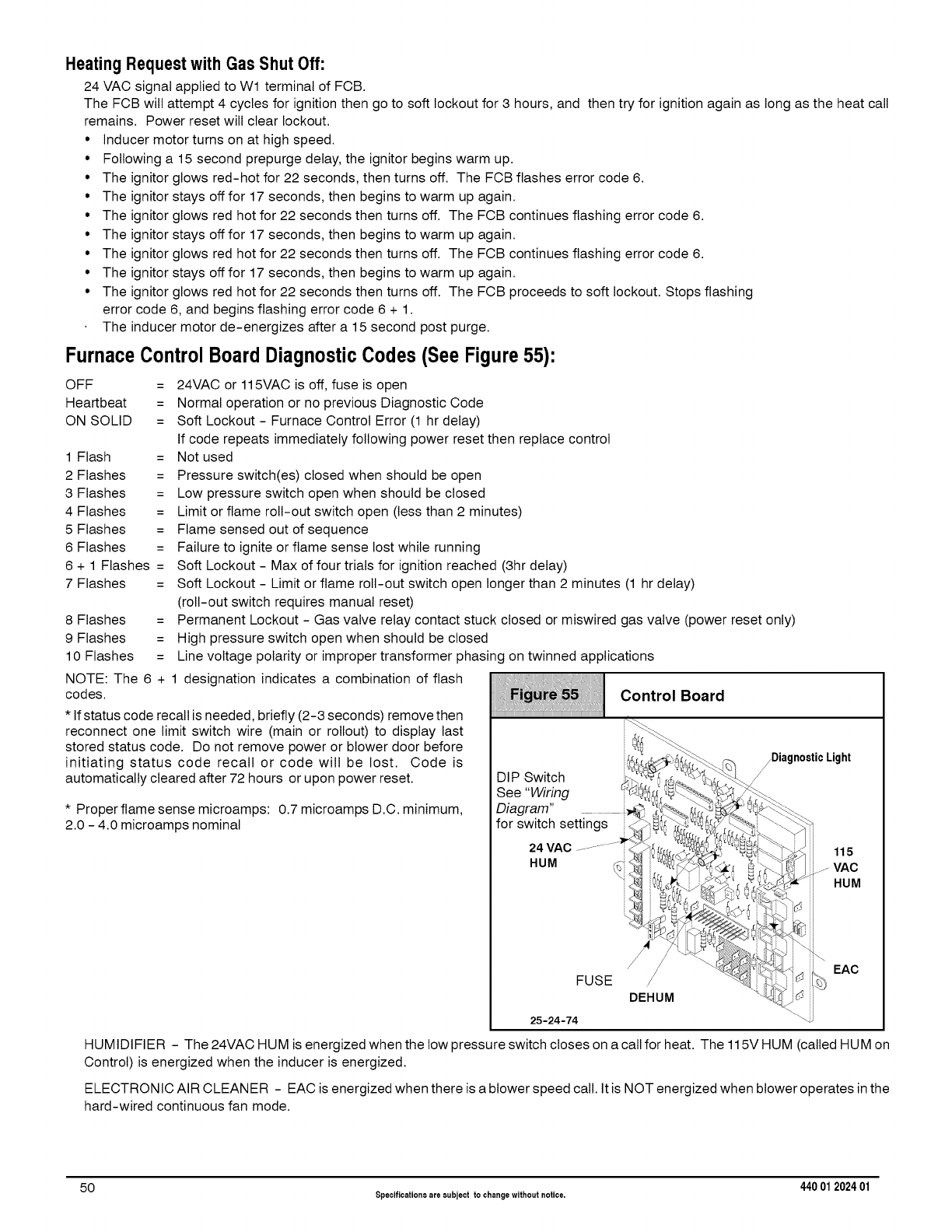
Heating Request with Gas Shut Off:
24 VAC signal applied to Wl terminal of FCB.
The FOB will attempt 4 cycles for ignition then go to soft lockout for 3 hours, and then try for ignition again as long as the heat call
remains. Power reset will clear lockout.
• Inducer motor turns on at high speed.
• Following a 15 second prepurge delay, the ignitor begins warm up.
• The ignitor glows red-hot for 22 seconds, then turns off. The FOB flashes error code 6.
• The ignitor stays off for 17 seconds, then begins to warm up again.
• The ignitor glows red hot for 22 seconds then turns off. The FOB continues flashing error code 6.
• The ignitor stays off for 17 seconds, then begins to warm up again.
• The ignitor glows red hot for 22 seconds then turns off. The FOB continues flashing error code 6.
• The ignitor stays off for 17 seconds, then begins to warm up again.
• The ignitor glows red hot for 22 seconds then turns off. The FOB proceeds to soft lockout. Stops flashing
error code 6, and begins flashing error code 6 + 1.
The inducer motor de-energizes after a 15 second post purge.
FurnaceControlBoard DiagnosticCodes (See Figure55):
OFF =
Heartbeat =
ON SOLID =
1 Flash =
2 Flashes =
3 Flashes =
4 Flashes =
5 Flashes =
6 Flashes =
6 + 1 Flashes =
7 Flashes =
8 Flashes =
9 Flashes =
10 Flashes =
24VAC or 115VAC is off, fuse is open
Normal operation or no previous Diagnostic Code
Soft Lockout - Furnace Control Error (1 hr delay)
If code repeats immediately following power reset then replace control
Not used
Pressure switch(es) closed when should be open
Low pressure switch open when should be closed
Limit or flame roll-out switch open (less than 2 minutes)
Flame sensed out of sequence
Failure to ignite or flame sense lost while running
Soft Lockout - Max of four trials for ignition reached (3hr delay)
Soft Lockout - Limit or flame roll-out switch open longer than 2 minutes (1 hr delay)
(roll-out switch requires manual reset)
Permanent Lockout - Gas valve relay contact stuck closed or miswired gas valve (power reset only)
High pressure switch open when should be closed
Line voltage polarity or improper transformer phasing on twinned applications
NOTE: The 6 + 1 designation indicates a combination of flash
codes.
*If status code recall is needed, briefly (2-3 seconds) remove then
reconnect one limit switch wire (main or roltout) to display last
stored status code. Do not remove power or blower door before
initiating status code recall or code will be lost. Code is
automatically cleared after 72 hours or upon power reset.
* Proper flame sense microamps: 0.7 microamps D.C. minimum,
2.0 - 4.0 microamps nominal
iiiiiiiiiiiiiiiiiiiiiiiiiiiiiiiiiiiiiiiiiiiiiiiiiiiiiiiiiiiiiiiiiiiiiiiiiiiiiiiiiiiiiiiiiiiiiiiiiiiiiiiiiiiiiiiiiiiiiiiiiiiiiiiiiiiiiiiiiiiiiiii
....... _:_ _"_.
See "Wiring _ _!!
Din-ram" .._ _ .... r_4;_
for switch settings _ _ fX, _
FUSE / // _\_
DEHUM
25-24-74
_Diagnostic Light
Control Board
-\.j
EAC
HUMIDIFIER - The 24VAC HUM is energized when the low pressure switch closes on a call for heat. The 115V HUM (called HUM on
Control) is energized when the inducer is energized.
ELECTRONIC AIR CLEANER - EAC is energized when there is a blower speed call. It is NOT energized when blower operates in the
hard-wired continuous fan mode.
50 Specificationsare eubject to changewithout notice. 440 012024 01
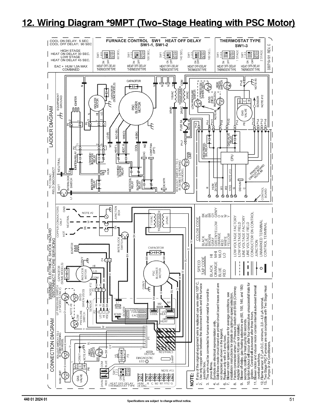
12. Wiring Diagram *9MPT (Two-Stage Heating with PSC Motor)
cooloNDELAY:5SEOIr ' -X
I COOLOFFDELAY: 90 SECI FURNACE CONTROLsw1=I,SWIsw1=2HEATOFF DELAY / THERMOSTATsw1=3 TYPE o
I HEAT ON DELAY 30 SEC. I u_ ',n _ co co _ _ _ _ '°
LOW STAGE I o o o o
HEAT ON DELAY 45 SEC' I Z 8 Z 0 _ Z8 Zo Z 8 _ z 8 _ '_1
I EAC + HUM 1.0A MAX HEATOFF-DELAY HEATOFF-DELAY HEATOFF-DELAY HEATOFF-DELAY / HEATOFFDELAY HEATOFF@ELAY
COMB NED THERMOSTATTYPE THERMOSTATTYPE THERMOSTATTYPE THERMOSTATTYPE |THERMOSTATTYPE_ERMOSTATTYPE _ I
15
<
UJ
I
I
>
I
C3
ad
1"
T
O3
18
IE
Zo
k.
5
S
Z
o r z
_-'% NOTE_2 Oi
,,___ - p#...f_-
_--" L__CJ
©
CAPACITOR
m
CAPACHOR
%
P
B
z_
,)
,)
>
z>_
_>_z _q
_O<_<_
_©©O_>
:S
88 :zz+
S
8
_m_©
<<_
©© --_
>>_b<_
oo_§_:s
"1t
, | o
i
,|
440 01 202401 Specificationsare subject to changewithout notice. 51
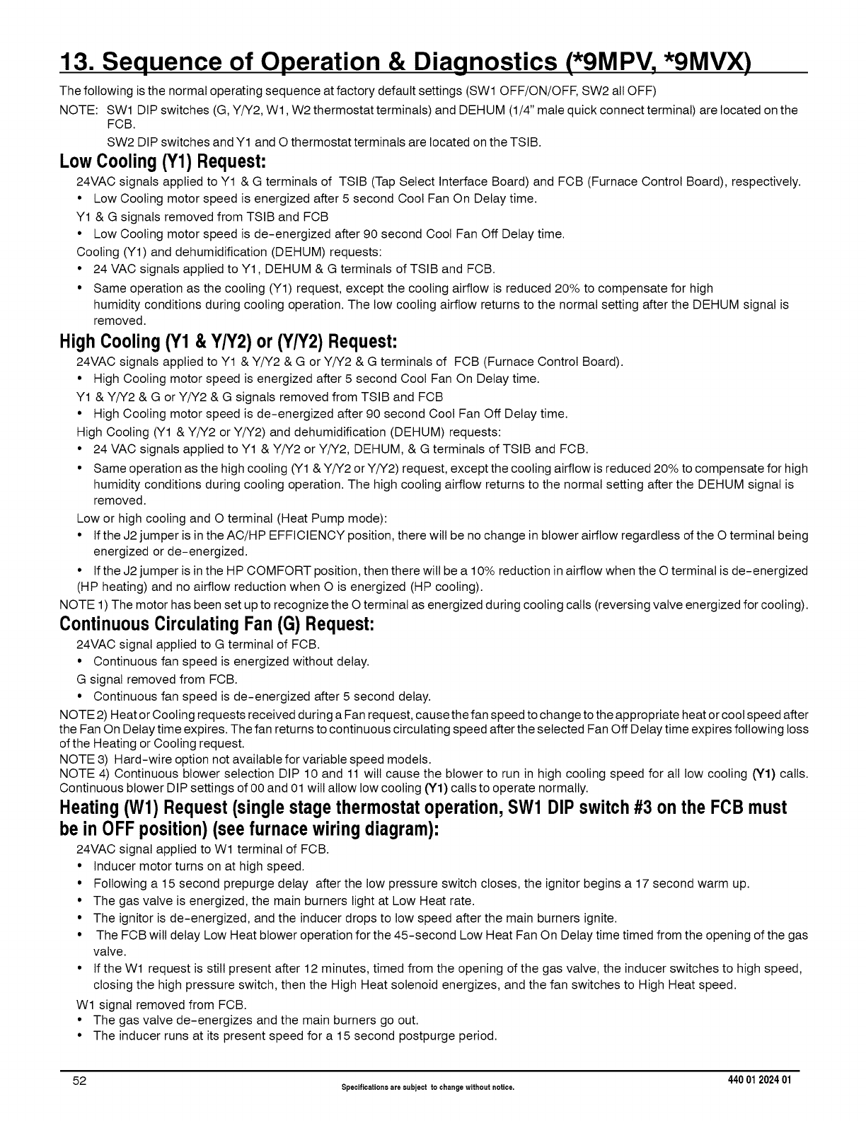
13. Sequence of Operation & Diagnostics (*9MPV, *9MV)0
The following is the normal operating sequence at factory default settings (SWl OFF/ON/OFF, SW2 all OFF)
NOTE: SWl DIP switches (G, Y/Y2, Wl, W2 thermostat terminals) and DEHUM (1/4" mate quick connect terminal) are located on the
FCB.
SW2 DIP switches and Y1 and O thermostat terminals are located on the TSIB.
Low Cooling(Y1) Request:
24VAC signals applied to Y1 & G terminals of TSIB (Tap Select Interface Board) and FCB (Furnace Control Board), respectively.
• Low Cooling motor speed is energized after 5 second Cool Fan On Delay time.
Y1 & G signals removed from TSIB and FCB
• Low Cooling motor speed is de-energized after 90 second Cool Fan Off Delay time.
Cooling (Y1) and dehumidification (DEHUM) requests:
• 24 VAC signals applied to Y1, DEHUM & G terminals of TSIB and FCB.
• Same operation as the cooling (Y1) request, except the cooling airflow is reduced 20% to compensate for high
humidity conditions during cooling operation. The low cooling airflow returns to the normal setting after the DEHUM signal is
removed.
High Cooling(Y1 l Y/Y2) or (Y/Y2) Request:
24VAC signals applied to Y1 & Y/Y2 & G or Y/Y2 & G terminals of FCB (Furnace Control Board).
• High Cooling motor speed is energized after 5 second Cool Fan On Delay time.
Y1 & Y/Y2 & G or Y/Y2 & G signals removed from TSIB and FCB
• High Cooling motor speed is de-energized after 90 second Cool Fan Off Delay time.
High Cooling (Y1 & Y/Y2 or Y/Y2) and dehumidification (DEHUM) requests:
• 24 VAC signals applied to Y1 & Y/Y2 or Y/Y2, DEHUM, & G terminals of TSIB and FCB.
• Same operation as the high cooling (Y1 & Y/Y2 or Y/Y2) request, except the cooling airflow is reduced 20% to compensate for high
humidity conditions during cooling operation. The high cooling airflow returns to the normal setting after the DEHUM signal is
removed.
Low or high cooling and O terminal (Heat Pump mode):
• If the J2 jumper is in the AC/HP EFFICIENCY position, there will be no change in blower airflow regardless of the O terminal being
energized or de-energized.
• If the J2 jumper is in the HP COMFORT position, then there wilt be a 10% reduction in airflow when the O terminal is de-energized
(HP heating) and no airflow reduction when O is energized (HP cooling).
NOTE 1) The motor has been set up to recognize the O terminal as energized during cooling calls (reversing valve energized for cooling).
ContinuousCirculatingFan(G) Request:
24VAC signal applied to G terminal of FCB.
• Continuous fan speed is energized without delay.
G signal removed from FCB.
• Continuous fan speed is de-energized after 5 second delay.
NOTE 2) Heat or Cooling requests received during a Fan request, cause the fan speed to change to the appropriate heat or cool speed after
the Fan On Delay time expires. The fan returns to continuous circulating speed after the selected Fan Off Delay time expires following loss
of the Heating or Cooling request.
NOTE 3) Hard-wire option not available for variable speed models.
NOTE 4) Continuous blower selection DIP 10 and 11 will cause the blower to run in high cooling speed for all low cooling 0'1) calls.
Continuous blower DIP settings of 00 and 01 will allow low cooling 0'1) calls to operate normally.
Heating(Wl) Request(singlestagethermostatoperation,SW1 DIP switch#3 on the FOBmust
be in OFF position) (see furnace wiring diagram):
24VAC signal applied to Wl terminal of FCB.
• Inducer motor turns on at high speed.
• Following a 15 second prepurge delay after the low pressure switch closes, the ignitor begins a 17 second warm up.
• The gas valve is energized, the main burners light at Low Heat rate.
• The ignitor is de-energized, and the inducer drops to low speed after the main burners ignite.
• The FCB wilt delay Low Heat blower operation for the 45-second Low Heat Fan On Delay time timed from the opening of the gas
valve.
• If the Wl request is still present after 12 minutes, timed from the opening of the gas valve, the inducer switches to high speed,
closing the high pressure switch, then the High Heat solenoid energizes, and the fan switches to High Heat speed.
Wl signal removed from FCB.
• The gas valve de-energizes and the main burners go out.
• The inducer runs at its present speed for a 15 second postpurge period.
52 Specificationsare subject to changewithout notice. 440 012024 01
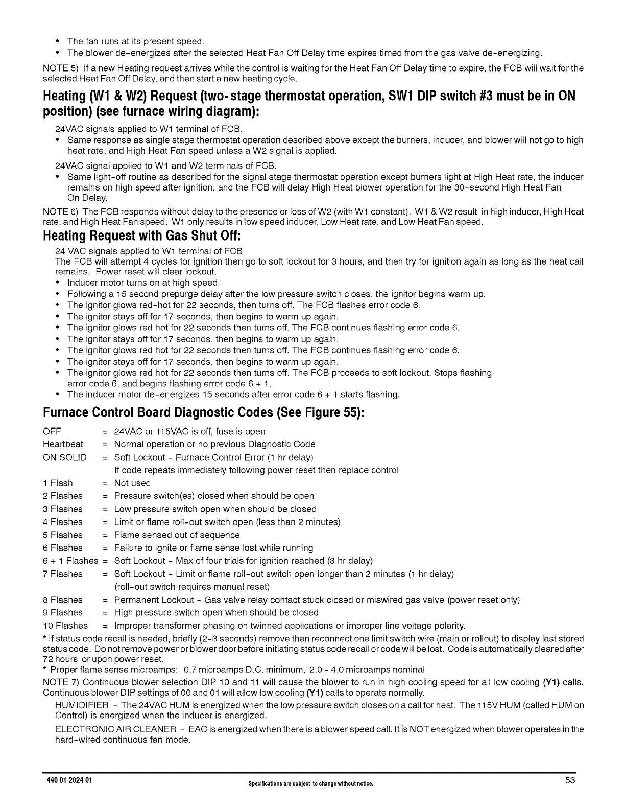
• The fan runs at its present speed.
• The blower de-energizes after the selected Heat Fan Off Delay time expires timed from the gas valve de-energizing.
NOTE 5) If a new Heating request arrives while the control is waiting for the Heat Fan Off Delay time to expire, the FCB will wait for the
selected Heat Fan Off Delay, and then start a new heating cycle.
Heating(Wl & W2) Request(two-stage thermostatoperation,SW1 DIP switch#3 mustbe in ON
position)(see furnacewiringdiagram):
24VAC signals applied to Wl terminal of FCB.
• Same response as single stage thermostat operation described above except the burners, inducer, and blower will not go to high
heat rate, and High Heat Fan speed unless a W2 signal is applied.
24VAC signal applied to Wl and W2 terminals of FCB.
• Same light-off routine as described for the signal stage thermostat operation except burners light at High Heat rate, the inducer
remains on high speed after ignition, and the FCB will delay High Heat blower operation for the 30-second High Heat Fan
On Delay.
NOTE 6) The FCB responds without delay to the presence or loss of W2 (with Wl constant). Wl & W2 result in high inducer, High Heat
rate, and High Heat Fan speed. Wl only results in low speed inducer, Low Heat rate, and Low Heat Fan speed.
Heating Requestwith Gas Shut Off:
24 VAC signals applied to Wl terminal of FCB.
The FCB will attempt 4 cycles for ignition then go to soft lockout for 3 hours, and then try for ignition again as long as the heat call
remains. Power reset will clear lockout.
• Inducer motor turns on at high speed.
• Following a 15 second prepurge delay after the low pressure switch closes, the ignitor begins warm up.
• The ignitor glows red-hot for 22 seconds, then turns off. The FCB flashes error code 6.
• The ignitor stays off for 17 seconds, then begins to warm up again.
• The ignitor glows red hot for 22 seconds then turns off. The FCB continues flashing error code 6.
• The ignitor stays off for 17 seconds, then begins to warm up again.
• The ignitor glows red hot for 22 seconds then turns off. The FCB continues flashing error code 6.
• The ignitor stays off for 17 seconds, then begins to warm up again.
• The ignitor glows red hot for 22 seconds then turns off. The FCB proceeds to soft lockout. Stops flashing
error code 6, and begins flashing error code 6 + 1.
• The inducer motor de-energizes 15 seconds after error code 6 + 1 starts flashing.
FurnaceControlBoard DiagnosticCodes (See Figure55):
OFF = 24VAC or 115VAC is off, fuse is open
Heartbeat = Normal operation or no previous Diagnostic Code
ON SOLID = Soft Lockout - Furnace Control Error (1 hr delay)
If code repeats immediately following power reset then replace control
1 Flash = Not used
2 Flashes = Pressure switch(es) closed when should be open
3 Flashes = Low pressure switch open when should be closed
4 Flashes = Limit or flame roll-out switch open (less than 2 minutes)
5 Flashes = Flame sensed out of sequence
6 Flashes = Failure to ignite or flame sense lost while running
6 + 1 Flashes = Soft Lockout - Max of four trials for ignition reached (3 hr delay)
7 Flashes = Soft Lockout - Limit or flame roll-out switch open longer than 2 minutes (1 hr delay)
(roll-out switch requires manual reset)
8 Flashes = Permanent Lockout - Gas valve relay contact stuck closed or miswired gas valve (power reset only)
9 Flashes = High pressure switch open when should be closed
10 Flashes = Improper transformer phasing on twinned applications or improper line voltage polarity.
* If status code recall is needed, briefly (2-3 seconds) remove then reconnect one limit switch wire (main or rollout) to display last stored
status code. Do not remove power or blower door before initiating status code recall or code will be lost. Code is automatically cleared after
72 hours or upon power reset.
* Proper flame sense microamps: 0.7 microamps D.C. minimum, 2.0 - 4.0 microamps nominal
NOTE 7) Continuous blower selection DIP 10 and 11 will cause the blower to run in high cooling speed for all low cooling (Y1) calls.
Continuous blower DIP settings of O0and 01 will allow low cooling (Y1) calls to operate normally.
HUMIDIFIER - The 24VAC HUM is energized when the low pressure switch closes on a call for heat. The 115V HUM (called HUM on
Control) is energized when the inducer is energized.
ELECTRONIC AIR CLEANER - EAC is energized when there is a blower speed call. It is NOT energized when blower operates in the
hard-wired continuous fan mode.
440 01 202401 Specificationsare subject to changewithout notice. 53
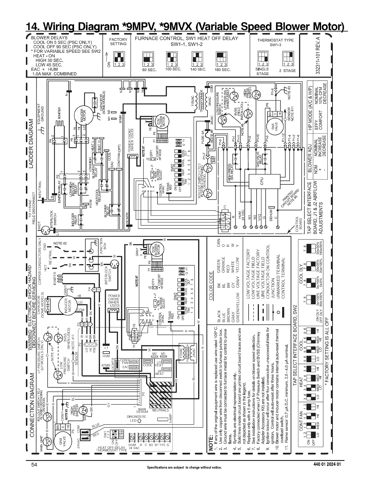
14. Wiring Diagram *9MPV, *9MVX (Variable S
:'BL_E_LA_S--"-- "
COOLON+SEC(PSCONLY)
I COOL OFF 90 SEC (PSC ONLY)
* FOR VARIABLE SPEED SEE SW2
HEAT -ON
HIGH 30 SEC.
LOW 45 SEC.
EAC + HUM
1,0A MAX COMBINED
I
12
c_
I _ I id
zl
_" 0 z_
I_
n ! !
FACTORY
SETTING
FURNACE CONTROL, SWl HEAT OFF DELAY
SWI-1, SW1-2
60 SEC. 100 SEC. 140 SEC. 180 SEC.
)eed Blower Motor)
B ! m m
THERMOSTAT TYPE
SW1-3
SINGLE 2 STAGE
STAGE
uJ
rY
5
uJ
o>_o
wO
O+ _
rn :7
_z_
t..- rn <
18
v_
J_
I
I
©
Z
0
Z
18
Im
_ z _:
z m NOTE #2 O x i
o _ "1_ I_ _ __
z _ ® m L pm`::+ Lmo>, _
_s _ ., ! i l_ow_RI I _. ._E:::Io+
--LolYI/_g _LO I I -_ I (WHEN I I PIS___ r-_=_ +
+ _ ++il i !1 14Ill I:.:+bT.__=o©
,. _1:_t77_>_!_ III +iF+M!_ _s_ "_
i&_1-/!-!_ _-_- _-_-
:::: >z _ :
_,o _ _z S _ _ o _ !
+++J+,,+/I :::Ig 0+
gS o _ , +=/+/I i H U + + _ ...... ! _ _ _ I +I C
s° I \ ,_:7?s/! I qit]W_A:177777]llf-_---ilLo_I -_
O_o_ I O _ -- COOL HEAT
g _
_1 i i CoLU_l /-_1 mDEIIUM NEUTRALS
+_11 _ _+_ _,A+NOS,,C+
_Pl _ LE00 C::::__
nl g.n.III _ <o _ __ A lI-Z-l_J--a
\A/II CO > 0 HUM R CW2 W YY20
_.J _. _ HEATOFE-DE AY 2zIVAC
_E "___ THERMOSTAT TYPE ......................................................................................................................
W_ _s
z
mmm©©
mmm©©
8
_w<wO z
WWLd
<<<_ 8_
_= OS 8
oooS _S
>>>8g_8
I'I II'
,Io
I
,I
++-_+M
Go
s _m_JS_
0 00_
0 llI,._ o _o
q I ga
_D
oS_
< ©
wo SV-
I-- t--
Z _ 0 LL!
o >-
:c ©
UJ m F'-
_- <_F_ u_°
<
F- I_ _0 *
0
L,_ _
2: tc
o_
54 Specificationsare subject to changewithout notice. 440 012024 01
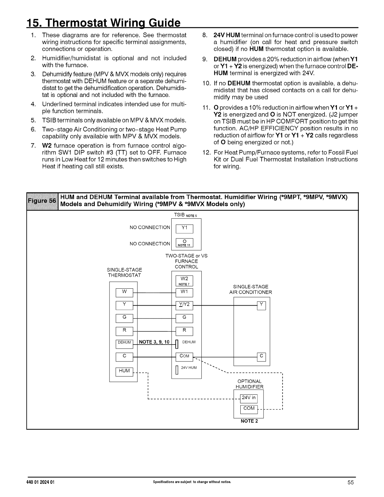
15. Thermostat Wiring Guide
1. These diagrams are for reference. See thermostat
wiring instructions for specific terminal assignments,
connections or operation.
2. Humidifier/humidistat is optional and not included
with the furnace.
3. Dehumidify feature (MPV & MVX models only) requires
thermostat with DEHUM feature or a separate dehumi-
distat to get the dehumidification operation. Dehumidis-
tat is optional and not included with the furnace.
4. Underlined terminal indicates intended use for multi-
ple function terminals.
5. TSIB terminals only available on MPV & MVX models.
6. Two-stage Air Conditioning or two-stage Heat Pump
capability only available with MPV & MVX models.
7. W2 furnace operation is from furnace control algo-
rithm SWl DIP switch #3 (TT) set to OFF. Furnace
runs in Low Heat for 12 minutes then switches to High
Heat if heating call still exists.
8. 24V HUM terminal on furnace control is used to power
a humidifier (on call for heat and pressure switch
closed) if no HUM thermostat option is available.
9. DEHUM provides a 20% reduction in airflow (when Y1
or Y1 + Y2 is energized) when the furnace control DE-
HUM terminal is energized with 24V.
10. If no DEHUM thermostat option is available, a dehu-
midistat that has closed contacts on a call for dehu-
midify may be used
11. O provides a 10% reduction in airflow when Y1 or Y1 +
Y2 is energized and O is NOT energized. (J2 jumper
on TSIB must be in HP COMFORT position to get this
function. AC/HP EFFICIENCY position results in no
reduction of airflow for Y1 or Y1 + Y2 calls regardless
of O being energized or not.)
12. For Heat Pump/Furnace systems, refer to Fossil Fuel
Kit or Dual Fuel Thermostat Installation Instructions
for wiring.
HUM and DEHUM Terminal available from Thermostat. Humidifier Wiring (*9MPT, *9MPV, *9MVX)
Models and Dehumidify Wiring (*9MPV & *9MVX Models only)
TSIB NOTE5
NO CONNECTION [_
NO CONNECTION
SINGLE-STAGE
THERMOSTAT
TWO-STAGEorVS
FURNACE
CONTROL
I " I
NOTE 3_ 9_ 10 "1] DEHUM
.... I
I
i
i
I
I
i
i
L
24V HUM -.
SINGLE-STAGE
AIR CONDITIONER
Fq
[]
OPTIONAL
HUMIDIFIER
NOTE2
44001 2024 01 Specifications are subject to change without notice. 55
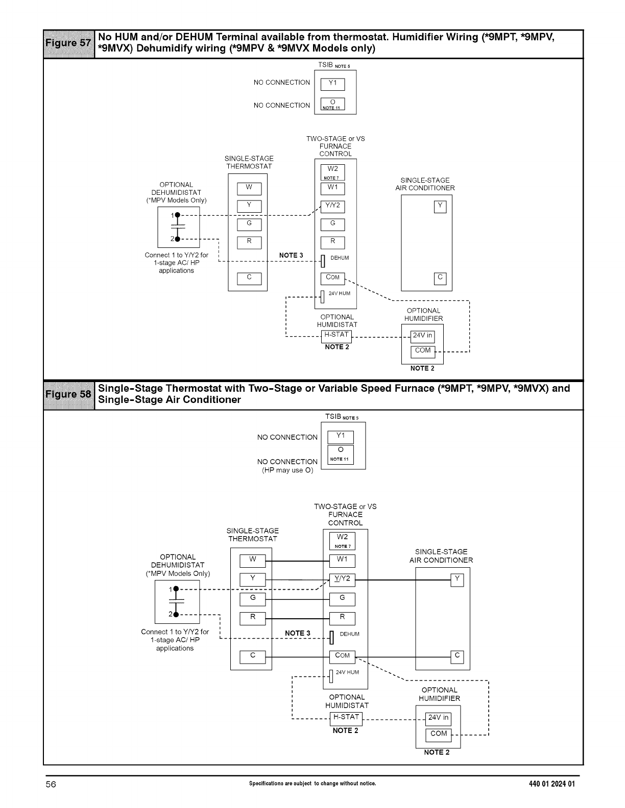
.o.0.an<,/o.O_,UMt°..,na,ava,,ab,°,ron,t,.°..ootat.,...,<,,,,°.W,r,n__.,_,_.,_,
*9MVX) Dehumidify wiring (*9MPV & *9MVX Models only)
TSIB NOTE 5
NO CONNECTION
NO CONNECTION
TWO-STAGEorVS
FURNACE
CONTROL
SINGLE-STAGE
THERMOSTAT
OPTIONAL
DEHUMIDISTAT I_
(*MPV Models Only) [_ , ,I_T_ 7
Connect 1 to Y/Y2 for , NOTE 3"1] DEHUM1-stage AC/HP L_.
applications
"1_ 24V HUM _.
i
i
1
' OPTIONAL
I
'HUMIDISTAT
1
NOTE 2
SINGLE-STAGE
AIR CONDITIONER
[]
[]
i
i
OPTIONAL
HUMIDIFIER i
i
i
_ '
NOTE2
NO CONNECTION
NO CONNECTION
(HP mayuseO)
Single-Stage Thermostat with Two-Stage or Variable Speed Furnace (*9MPT, *9MPV, *9MVX) and
Single-Stage Air Conditioner
TSIB NOTE 5
F_q
SINGLE-STAGE
TH ERMOSTAT
OPTIONAL
DEHUMIDISTAT I_
(*MPV Models Only) I I
:_t_.........r_=7............
Connect 1 to Y/Y2 for
1-stage AC/HP
applications
i
i
'NOTE 3
L-.
_q
i ......
i
i
i
i
i
i
i
i
TWO-STAGE or VS
FURNACE
CONTROL
F_q
•.._ DEHUM
..._ 24V HUM _
OPTIONAL
HUMIDISTAT
NOTE 2
SINGLE-STAGE
AIR CONDITIONER
[]
[]
i
i
OPTIONAL
HUMIDIFIER i
i
_ ,
- i
i
_ '
....... l
NOTE2
56 Specifications are subject to change without notice, 440 01 202401
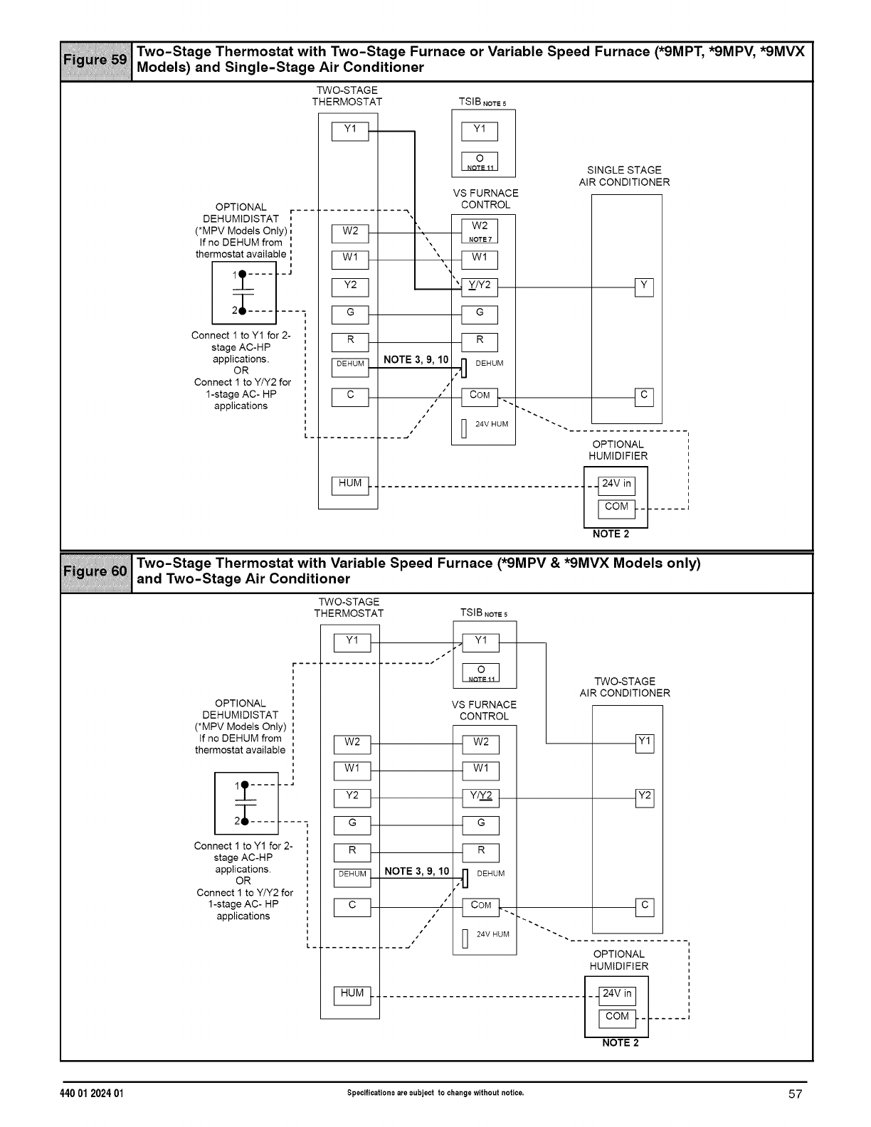
__ Two-Stage Thermostat with Two-Stage Furnace or Variable Speed Furnace (*9MPT, *9MPV, *9MVX
Models) and Single-Stage Air Conditioner
TWO-STAGE
THERMOSTAT TSIB NOTE5
OPTIONAL r
DEHUMIDISTAT ,
(*MPV Models Only) _
If no DEHUM from '_
thermostat available '_
i
___ -'
i
i
i
Connect 1 toY1 for 2- ,
i
stage AC-HP
applications. ,'
OR '
i
Connect 1 to Y/Y2 for ,
1-stage AC- HP ',
applications
F_q
F_q
_q
_q
F_q
\
NOTE 3, 9, 10
i
•s
•#
SINGLE STAGE
AIR CONDITIONER
OPTIONAL
HUMIDIFIER
VS FURNACE
CONTROL
F_q
F_q
_q
zD DEHUM
Fq
[]
NOTE 2
i
i
i
i
i
i
i
i
i
i
i
_i
Two-Stage Thermostat with Variable Speed Furnace (*9MPV & *9MVX Models only)
and Two-Stage Air Conditioner
TWO-STAGE
THERMOSTAT TSIB NOTe5
ir....
i
i
I
i
OPTIONAL
DEHUMIDISTAT _
(*MPV Models Only) ',
If noDEHUM from ,
thermostat available _,
i
i
i
i
Connect 1toY1 for 2- ,
i
stage AC-HP
applications. ',
OR
Connect 1toY/Y2 for ,
1-stage AC- HP ',
applications ,
I._.
F_q
F_q
F_q
_q
_q
NOTE 3, 9, 10
t¢
J
VS FURNACE
CONTROL
F_q
F_q
F_q
F_q
_q
,•'1] DEHUM
I] 24V HUM
TWO-STAGE
AIR CONDITIONER
_q
[]
OPTIONAL
HUMIDIFIER
i
i
i
i
i
i
i
i
i
i
i
...... |
NOTE 2
44001 2024 01 Specifications are subject to change without notice, 57

THIS PAGE LEFT
BLANK
INTENTIONALLY
58 Specifications are subject to change without notice. 440 01 202401
