ICP Evaporator Coils Manual LR708241
User Manual: ICP ICP Evaporator Coils Manual ICP Evaporator Coils Owner's Manual, ICP Evaporator Coils installation guides
Open the PDF directly: View PDF ![]() .
.
Page Count: 14
I Installation Instructions Fan Coils I
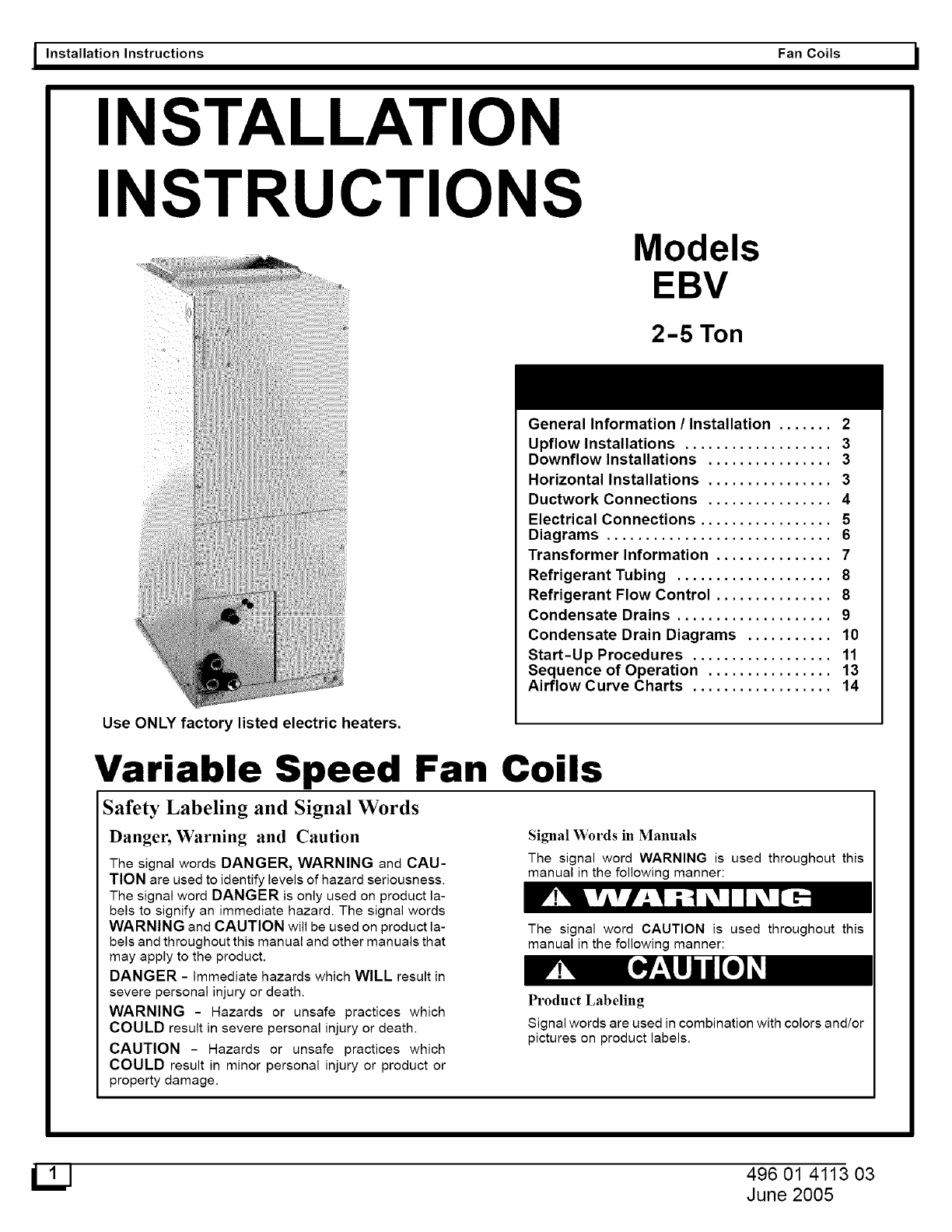
INSTALLATION
INSTRUCTIONS
Models
EBV
2-5 Ton
General Information /Installation ....... 2
Upflow Installations ................... 3
Downflow Installations ................ 3
Horizontal Installations ................ 3
Ductwork Connections ................ 4
Electrical Connections ................. 5
Diagrams ............................. 6
Transformer Information ............... 7
Refrigerant Tubing .................... 8
Refrigerant Flow Control ............... 8
Condensate Drains .................... 9
Condensate Drain Diagrams ........... 10
Start-Up Procedures .................. 11
Sequence of Operation ................ 13
Airflow Curve Charts .................. 14
Use ONLY factory listed electric heaters.
Variable Speed Fan Coils
Safety Labeling and Signal Words
Danger, Warning and Caution
The signal words DANGER, WARNING and CAU-
TION are used to identify levels of hazard seriousness.
The signal word DANGER is only used on product la-
bels to signify an immediate hazard. The signal words
WARNING and CAUTION will be used on product la-
bels and throughout this manual and other manuals that
may apply to the product.
DANGER - Immediate hazards which WILL result in
severe personal injury or death.
WARNING - Hazards or unsafe practices which
COULD result in severe personal injury or death.
CAUTION - Hazards or unsafe practices which
COULD result in minor personal injury or product or
property damage.
Signal Words in Manuals
The signal word WARNING is used throughout this
manual in the following manner:
The signal word CAUTION is used throughout this
manual in the following manner:
Product Labeling
Signal words are used in combination with colors and/or
pictures on product labels.
496 01 4113 03
June 2005

I Installation Instructions Fan Coils I
Figure 1 J Clearances& Dimensions
Unit Sizes
2400
3600
4800
6000
A
15-3/4"
19-1/4"
19-1/4"
22-3/4"
BC
11" 1_1_1_'
11" 1_1_1_'
11" 1_1_1_'
11" 1_1_1_'
D
15-5/8"
19-1/8"
19-1/8"
22-11/16"
E
22-1/16"
22-1/16"
22-1/16"
22-1/16"
F
17-5/8"
21-1/8"
21-1/8"
24-11/16"
CLEARANCES
NO HEATERS
All Sides ................................... 0"
From Supply Duct .......................... 0"
Recommended Service From Front .......... 20"
(Service for blower, filter if installed)
WITH HEATERS
All Sides .................................. 0"
From First Three Feet of Supply Duct to Combus-
tibles ...................................... 1"
From Duct after Three Feet ................. 0"
Recommended Service From Front .......... 20"
Fire Hazard
When heaters are installed maintain clearances
from combustible materials as specified on unit
rating plate. Do not use plastic lined or combustible
flexible ducting within 36 inches of the supply end of
the air handler.
Failure to do so can result in fire, property damage,
personal injury or death.
G
47-11/16"
53-7/16"
53-7/16"
59-3/16"
General Information
Installation or repairs made by unqualified persons
can result in hazards to you and others. Installation
MUST conform with local building codes and with the
National Electrical Code NFPA70 current edition.
The information contained in this manual is intended
for use by a qualified service technician familiar with
safety procedures and equipped with the proper
tools and test instruments.
Failure to carefully read and follow all instructions in
this manual can result in equipment malfunction,
property damage, personal injury and/or death.
The blower cabinet may be used for cooling or heat pump operation with
or without electric heat. The cabinet can be installed in an upflow or
horizontal position (Figure 2, 3). EBV models are shipped with the hori-
zontal kit already installed.
Location
Select the best position which suits the installation site conditions. The
location should provide adequate structural support, space in the front of
the unit for service access, clearance for return air and supply duct con-
nections, space for refrigerant piping connections and condensate
drain line connections. If heaters are being installed make sure ade-
quate clearance is maintained from supply ductwork, (see Fig. 1).
NOTE: Internal filter can be accessed from separate filter door. If the
filter can NOT be easily accessed, a remote filter is recommended. Re-
fer to ACCA Manual D for remote filter sizing.
If the unit is located in an area of high humidity, nuisance sweating of
casing may occur. On these installations a wrap of 2" fiberglass insula-
tion with a vapor barrier is recommended.
UJ

i Fan Coils
INTRODUCTION
The EBV model is designed for flexibility and can be used for upfiow,
horizontal, or downfiow (kit required) applications. These units are avail-
able for systems of 24,000 through 60,000 Btuh nominal cooling capac-
ity. Factory authorized electric heater packages are available in sizes 5
through 30kw. See Product Specification Literature for available acces-
sory kits.
HEATER PACKAGES
A factory approved, field installed UL listed heater package is available
from your equipment supplier. See unit rating plate for a list of factory
approved heaters. Heaters that are not factory approved could cause
damage which would not be covered under the equipment warranty.
INSTALLATION
PROCEDURE 1-CHECK EQUIPMENT
Unpack unit and move to final location. Remove carton taking care not
to damage unit. Inspect equipment for damage prior to installation. File
claim with shipping company if shipment is damaged or incomplete. Lo-
cate unit rating plate which contains proper installation information.
Check rating plate to be sure unit matches job specifications.
Installation Instructions
Slope Coil Unit In Upflow Application
018-06021 IN, FRONT SERVICE
070 24-1N CLEARANCE
UPFLOW/DOWNFLOW
UP FLOW/DOWNFLOW --
SEOONDARy DRAIN
UP FLOW/DOWNFL
PRIMARY DRAIN
SUPPLY DUCT
ENTRY
OPTIONS
Unit A
2400-3600 17 in
4200-6000 19 in
½-
FIELD MODIFIED
ASIDE RETURN
LOCATION FOR
SLOPE COIL
UNITS ONLY
PROCEDURE 2- MOUNT FAN COIL
Unit can stand or lie on floor, or hang from ceiling or wall. Allow space
for wiring, piping, and servicing unit.
NOTE: To ensure proper drainage for horizontal installations, unit must
be installed so it is within 118 in. level of the length and width of unit.
A. Upflow Installation
If return air is to be ducted, install duct flush with floor. Set unit on floor
over opening. Only use return-air opening provided. All return air must
pass through the coil. (See Fig. 2.)
B. Modular Units
The EBV Fan Coil in size 6000 is a 2-piece modular unit. Modular
construction allows installer to disassemble unit into 2 components, coil
box and blower box, for ease of installation. (See Fig. 4)
To disassemble unit, remove rear corner brackets by removing 2
screws which secure brackets. (See Fig. 4) Remove either 2 screws in
each front corner of coil box, or 2 screws in blower box. Do not remove
all 4 screws in each corner. (See Fig. 4) Sections may now be separated
by lifting top section from lower section. To reassemble, reverse above
procedure. Be certain to reinstall all fasteners when reassembling.
C. Horizontal Installation
Be sure installation complies with all applicable building codes that may
require installation of secondary condensate pan.
1. Arrange support for unit by setting it in or above secondary conden
sate drain.
2. When suspending unit from ceiling, dimples in casing indicate proper
location of screws for mounting metal support straps (See Fig. 3)
UNIT or PROPERTY DAMAGE HAZARD
Failure to follow this caution may result in property damage.
A field fabricated auxiliary drain pan, with aseperate drain is
REQUIRED for all installations over a finished living space
or in any area that may be damaged by overflow from a re-
stricted main drain pan. In some localities, local codes re-
quire an auxiliary drain pan for ANY horizontal installation.
NOTE: For optimum condensate drainage performance in hori-
zontal installations, unit should be leveled along it's length or
raised 1/4" at the air inlet. The unit should also be pitched forward
1/4" to 1/2" toward the front condensate drains.
NOTE: Modular units can be disassembled and components moved
separately to installation area for reassembly. This process accommo-
dates small scuttle holes and limiting entrances to installation sites.
D. Horizontal-Right Conversion of Units with Slope Coils
NOTE: Gasket kit number EBAC01GSK is required for horizontal slope
coil conversion to maintain low air leak/low sweat performance.
1. Remove blower and coil access panels and fitting panel. (See Fig. 5.)
2. Remove screw securing coil assembly to right side casing flange.
3. Remove coil assembly.
4. Lay fan coil on its right side and reinstall coil assembly with conden-
sate pan down. (See Fig. 5.)
5. Attach coil to casing flange using coil mounting screw previously
removed.
6. Make sure the pan cap in the fitting door is properly seated on the fit
ting door to retain the low air leak rating of the unit.
7. Add gaskets from kit EBAC01GSK per kit instructions.
6. Align holes with tubing connections and condensate pan connec-
tions, and reinstall access panels and fitting panel. Make sure liquid
and suction tube grommets are in place to prevent air leaks and
cabinet sweating. Install after brazing.
E. Horizontal Right Conversion of Units With A-Coil
1. Remove blower and coil access panel and fitting panel.(See Fig. 6).
2. Remove metal clip securing fitting panel to condensate pan. Remove
fitting panel.
3. Remove 2 snap-in clips securing A-coil in unit.
4. Slide coil and pan assembly out of unit.
5. Remove horizontal drain pan support bracket from coil support rail on
left side of unit and reinstall on coil support rail on right side of unit.
6. Convert air-seal assembly for horizontal right. (See Fig. 6).
A. Remove air-seal assembly from coil by removing 4 screws.
B Remove coil drip flanges from A-coil and reinstall on right side of
coil (same side as horizontal drain pan).
C. Remove filler plate (A) and install air splitter (B) in place of filler
plate.

I Installation Instructions Fan Coils I
D. Install filler plate (A) as shown in horizontal right application.
E. Remove condensate troughs (C) and install on opposite tube
sheets.
R install hose onto plastic spout.
7. Install horizontal pan on right side of coil assembly.
8. Slide coil assembly into casing. Be sure coil bracket on each corner
of vertical pan engages coil support rails.
9. Reinstall 2 snap-in clips to correctly position and secure coil assem-
bly in unit. Be sure clip with large offsets is used on right side of unit
to secure horizontal pan.
10. Remove 2 oval coil access panel plugs and reinstall into holes on left
side of coil access panel and fitting panel.
11. Remove insulation knockouts on right side of coil access panel
12. Reinstall access fitting panels, aligning holes with tubing connec-
tions and condensate pan connections. Be sure to reinstall metal
clip between fitting panel and vertical condensate pan.
Make sure liquid and suction tube grommets are in place to prevent air
leaks and cabinet sweating.
F. Downflow Installations
To convert units for downflow applications, refer to Installation Instruc-
tions supplied with kit for proper installation.
G. Manufactured and Mobile Home Housing Applications
1. Fan coil unit must be secured to the structure using field-supplied
hardware.
2. Allow a minimum of 24" clearance from access panels.
3. Recommended method of securing for typical applications
a. If fan coil is away from wall, attach pipe strap to top of fan coil
using No. 10 self tapping screws. Angle strap down and away
from back of fan coil, remove all slack, and fasten to wall stud of
structure using 5/16-in. lag screws. Typically both sides of fan
coil.
b. If fan coil is against wall, secure fan coil to wall stud using
1/8-in. thick right-angle brackets. Attach brackets to fan coil us
ing No. 10 self tapping screws and to wall stud using 5116-in. lag
screws. (See Fig. 9).
PROCEDURE 3-AIR DUCTS
Connect supply-air duct over the outside of 3/4-in. flanges provided on
supply-air opening. Secure duct to flange, using proper fasteners for
type of duct used, and seal duct-to-unit joint. If return-air flanges are
required, install factory authorized accessory kit.
Use flexible connectors between ductwork and unit to prevent trans-
mission of vibration. When electric heater is installed, use heat-resist-
ant material for flexible connector between ductwork and unit at
discharge connection. Ductwork passing through unconditioned space
must be insulated and covered with vapor barrier.
Ductwork Acoustical Treatment
Metal duct systems that do not have a 90 degree elbow and 10 ft. of
main duct to first branch take off may require internal acoustical insula-
tion lining. As an alternative, fibrous ductwork may be used if
constructed and installed in accordance with the latest edition of SMAC-
NA construction standard on fibrous glass ducts. Both acoustical lining
and fibrous ductwork shall comply with National Fire Protection Associa-
tion as tested by UL Standard 181 for Class 1 air ducts.
Figure3 ] Slope Coil In Horizontal Left Application
LOW VOLT
ENTRY
OPTIONS
FIELD
SUPPLIED
HANGING _
STRAPS _,_] 018-060 21-IN.
FRONT SERVICE
CLEARANCE
UNIT _ (FULL FAC i
I 6F UNIT)
I-t1_, F_/__ll FtLTERACCESS
I "_'.._.)_J.!_ CLEARANCE
DRAIN
SECONDARY
POWER DRAIN
ENTRY OPTIONS
UJ

IFan Coils
Figure 4 Removal of Brackets on Modular Units
{
EWSI
BRACKET
2SCREWS
COiL 80X
Installation Instructions J
' Ure1Conversion for Horizontal Right
Applications Using a Slope Coil
COiL MOUNTING
CONNECTIONS
BLOWER
ASSEMBLY
COIL
RAIL
SLOPE COIL,
SKI
"PRIMARY DRAIN
-OVERFLOW HOLE
' SECONDARY DRAIN
PROCEDURE 4-ELECTRICAL CONNECTIONS
On units with a factory installed disconnect with pull-out removed, ser-
vice and maintenance can be safely performed on only the load side of
the control package.
SHOCK and UNIT DAMAGE HAZARD
Failure to follow this warning could result in personal injury or
death and unit damage.
Field wires on the line side of the disconnect found in the fan
coil unit remain live, even when the pull-out is removed. Ser-
vice and maintenance to incoming wiring can not be per-
formed until the main disconnect switch (remote to the unit)
is turned off. Failure to do so will result in electrical shock
causing personal injury or death.
Before proceeding with electrical connections, make certain that supply
voltage, frequency, phase, and ampacity are as specified on the unit rat-
ing plate. See unit wiring label for proper field high- and low-voltage
wiring. Make all electrical connections in accordance with the NEC and
any local codes or ordinances that may apply. Use copper wire only. The
unit must have a separate branch electric circuit with a field-supplied
disconnect switch located within sight from and readily accessible from
the unit.
Figure 6 IApplicationsC°nversi°nfOrusingHOrizontalA_coilRight
SUPPORT
RAIL
-AIR SEAL
CONNECTIONS ASSEMBLY HORtZONTAL
RIGHT
APPLICATION
BRACKET
SUPPORT
BRACKET
COIL_
SUPPORT
RAIL
HORIZONTAL RIGHT
SECONDARY DRAIN
HORIZONTAL RIGHT

I Installation Instructions
HORIZONTAL LEFT
Fan Coils I
4" MAX
4" MAX
SECURE FAN COILTO STRUCTUREUNIT AWAY FROM WALL
PIPE STRAP
(TYPICAL BOTH SIDES)
OR
UNIT AGAINST WALL
1/8-IN,THICK ANGLE
MOUNTING BRACKET
(TYPICAL BOTH SIDES)
13_ FLOW
-- BASE KIT
7(EBAC)
SECURE UNITTO FLOOR
ANGLE BRACKET OR PiPE STRAP
_I 0-;_6_;0£b(1133
VIOSS
A. Line Voltage Connections
If unit contains an electric heater, remove and discard power plug from
fan coil and connect male plug from heater to female plug from unit wir-
ing harness. (See Electric Heater Installation Instructions.)
For units without electric heat:
1. Connect 208/230v power leads from field disconnect to yellow and
black stripped leads.
2. Connect ground wire to unit ground lug.
NOTE: Units installed without electric heat should have a field-supplied
sheet metal block-off plate covering the heater opening. This will re-
duce air leakage and formation of exterior condensation.
ELECTRIC SHOCK HAZARD
Failure to follow this warning could result in personal injury
or death and unit damage.
Before installing or servicing system, always turn off all pow-
er to system. There may be more than I disconnect switch.
Turn off accessory heater power if applicable.
NOTE: Before proceeding with electrical connections, make certain that
supply voltage, frequency, and phase are as specified on unit rating
plate. Be sure that electrical service provided by the utility is sufficient
to handle the additional load imposed by this equipment. See unit wir-
ing label for proper field high- and low-voltage wiring. Make all electri-
cal connections in accordance with NEC and any local codes or
ordinances that may apply. Use copper wire only. The unit must have
a separate branch electric circuit with a field-supplied disconnect
switch located within sight from, and readily accessible from the unit.

I Fan Coils
B. 24-v Control System
CONNECTION TO UNIT
Wire low voltage in accordance with wiring label on the blower. (See Fig.
8, 10, 11, 12, 13 and 14). Use no. 18 AWG color-coded, insulated (35
C minimum) wire to make the low-voltage connections between the
thermostat, the unit, and the outdoor equipment. If the thermostat is lo-
cated more than 100 ft. from the unit (as measured along the low-volt-
age wire), use No. 16 AWG color-coded, insulated (35 C minimum)
wire. All wiring must be NEC Class 1 and must be separated from in-
coming power leads. Refer to outdoor unit wiring instructions for any
additional wiring procedure recommendations.
TRANSFORMER INFORMATION
Transformer is factory-wired for 230v operation. For 208v applications,
disconnect the black wire from the 230v terminal on transformer and
connect it to the 208v terminal. (See Fig. 14).
HEATER STAGING
The controls are factory circuited for single-stage operation. When 2
or 3 stages are desired, remove J2 (Jumper-2) from the control board.
(See Fig. 13).
Figure 10 IWiring Layout A/C Unit, No Heat
Thermostat Cooling Only
R
G--
Y
W
_2
©©
W 2 W 1 GY O H
IndoorBlower
Y
Y
Outdoor Unit
Air Conditioner - Adding Control for 80% Airflow
O©O O OO
W2 W 1 G Y O H C R
IndoorBlower
Dehumidistat or Outdoor Thermostat
Installation Instructions
(Cooling and 1-Stage Heat)
Thermostat
_. Y
t_Hf_r I Inif
Air Conditioner - Adding Control for 80% Airflow
©^_2_ © © © O R
W2W 1 GY O H C
Indoor Blower
Dehumidistat or Outdoor Thermostat
(Cooling and 2-Stage Heat)
Electric Heat Staging
Thermostat
*J2 Removed
Air Conditioner - Adding Control for 80% Airflow
O O G l> O O O O
W 2 W 1 G Y O H C R
Indnnr Blnw_r
Dehumidistat or Outdoor Thermostat
*J2 Removed

I Installation Instructions
C. Ground Connections
ELECTRICAL SHOCK HAZARD
Failure to follow this warning could result in electric shock,
fire, or death.
According to NEC, ANSI/NFPA 70, and local codes, the cabinet
must have an uninterrupted or unbroken ground to minimize
personal injury if an electrical fault should occur. The ground
may consist of electrical wire or metal conduit when installed
in accordance with existing electrical codes. If conduit con-
nection uses reducing washers, a separate ground wire must
be used.
NOTE: Use UL-listed conduit and conduit connector for connecting
supply wire(s) to unit to obtain proper grounding. Grounding may also
be accomplished by using grounding lugs provided in control box.
D. Fan Control Board Jumper Instructions
The fan control board (see Fig. 8) has two jumpers. Jumper 1 (JP1)
jumpers two of three pins. The control unit should be factory set to the
VS (variable speed) position and should be left in this position in most
cases.
If there is a motor or control failure, and a variable speed replacement is
not readily available, it may be necessary to use a PSC motor until the
proper part can be ordered. This "limp mode" can be accessed by
moving JP 1 to the PSC pins. In this position a PSC motor can replace the
VS motor.
Jumper 2 (J2) is used to stage electric heaters. When in place, J2 ties
Wl and W2 together which should be used for single stage heat. When
J2 is removed, it allows Wl and W2 to be controlled separately and is for
applications using two stage electric heating.
MotorSpeedsand Airflow
See Figure 15
The motor speed can be set on one of eight speeds and the air flow will
adjust between 60%, 80% and 100% depending on settings. Time ON /
OFF settings can also be adjusted.
Determine coil static pressure drop, consult coil manual and measure
duct system static pressure, then determine required speed setting
from blower charts.
For Cooling/HP Heating - Set switches 6, 7, and 8 on the motor control
to position 0 (off) or 1 (on) as specified on blower charts.
For Electric Heating - Set switches 3, 4, and 5 on the motor control to
position 0 (off) or 1 (on) as specified on blower charts.
Fan Coils I
Set switches 1 and 2 to position 0 (off) or 1 (on) as specified in Figure 12
to control Fan delay ON - OFF.
NOTE: Power must be completely OFF to unit any time switch
settings are changed or settings will not take effect.
Adding Humidistator OutdoorThermostat
Adding a humidistat or outdoor thermostat allows the airflow to be
reduced to 80% of normal allowing greater humidity control.
Humidistats are preferred but an outdoor thermostat can be used but
can only be set based on temperature. Suggested starting point is 85 F,
but this will vary depending on several factors.
The control must be wired differently on air conditioners and heat
pumps. On air conditioners connect to Y and Dehum terminals H, (see
Figure 10).
HEAT PUMPS ONLY: Heat pumps must use only the outdoor
thermostat, because it is powered instead of just performing a switching
function. This allows it to be out of the circuit when continuous
circulation is desired, which is required for the system to operate on Fan
Only for circulation, which is 60% airflow. On heat pumps connect to Y
and Dehum terminals H, and C and O to power the outdoor thermostat
(see Figure 12).
NOTE: The outdoor thermostat is not used for this application and if W
and H are energized at the same time, the unit will not run. The powered
outdoor thermostat only allows H to be energized when the system is
in the cooling mode.
PROCEDURE 5-REFRIGERANT TUBING AND FLOW CONTROL
Field-supplied tubing must be of refrigerant grade. Suction tube must
be insulated. Do not use damaged, dirty, or contaminated tubing be-
cause it may plug refrigerant flow-control device. ALWAYS evacuate
the coil and field-supplied tubing to 500 microns before opening out-
door unit service valves.
UNIT DAMAGE HAZARD
Failure to follow this caution may result in unit damage.
Braze with SiI-Fos or Phos-copper on copper to copper joints
and wrap a wet cloth around rear of fitting to prevent damage
to TXV.
UNIT DAMAGE HAZARD
Failure to follow this caution may result in unit damage.
If using an EBV model with field installed TXV in conjunc-
tion with a single-phase reciprocating compressor, a com-
pressor hard start kit is required.

IFan Coils
_u,e W,.n_.a_outHeatPu_,.o.oat
Installation Instructions J
Heat Pump
Staging
Thermostat
R
G
C
O
Y
W
Heat Pump Only
--R
BL
w
Y
J2
W 2 W 1 G Y O HCR
IndoorBlower
o
Outdoor Unit
Heat Pump - Adding Control for 80% Airflow
©0o
W2W 1 G Y O H C
IndoorBlower
k
Outdoor Thermostat

I InstallationInstructions FanCoils I
Figure !3 Typical Low Voltage Control Schematic For Heat Pumps
Heat Pump with 1-Stage Electric Heat ElectricHeat Heat Pump with 2-Stage Electric Heat
Heat Pump Staging Thermostat
Heat Pump
Staging Thermostat
R
G
C
O
Y
W
lW W 1 G Y O H
Indoor Blower
O
Outdoor Unit
C R
Heat Pump - Adding Control for 80% Airflow
R
BL
W
Y
R
G
O
Y
W 1
W2 m
G Y O H C
indoorBlower
)
R
R
BL
W
Y
O
Outdoor Unit
*J2 Removed
Heat Pump - Adding Control for 80% Airflow
Outdoor Thermostat
J2
0©000000
W2W1G Y O H C R
Indoor Blower
Outdoor Thermostat
O000oo()o
W2W1G Y O H C R
Indoor Blower
* J2 Removed
llj2J

Installation Instructions JI Fan Coils
,gure,, 1 Transformer Connections
RED
BLK
Heat Cool
Time CFM CFM
Delay Select Select Select
1 2 3 4567
I
1 Positions (on)
8 0 Switch (off)
Time Delays:
(0,0) = 30 Seconds
(0,1) = 60 Seconds
(1,0) = 90 Seconds (factory setting)
(1,1) = 0 Seconds
PROCEDURE 6-CONDENSATE DRAINS
Units are equipped with primary and secondary 3/4-in. FPT drain con-
nections. For proper condensate line installations see Fig. 2, 3, 5, 6 and
7. To prevent property damage and achieve optimum drainage perfor-
mance, BOTH primary and secondary drain lines should be installed
and include properly-sized condensate traps. (See Fig. 17). Factory-
approved condensate traps are available (Kit No. EBAC01CTK1). Be
sure to install plastic push-in plugs in unused condensate drain fittings.
It is recommended that PVC fittings be used on the plastic condensate
pan. Finger-tighten plus 1-1/2 turns. Do not over-tighten. Use pipe
dope.
UNIT or PROPERTY DAMAGE HAZARD
Failure to follow this caution may result in property damage
Shallow, running traps are inadequate and DO NOT allow prop-
er condensate drainage. (See Fig. 18).
When connecting condensate drain lines, avoid blocking filter ac-
cess panel, thus preventing filter removal. After connection, prime
both primary and secondary condensate traps.
NOTE: When connecting condensate drain lines, avoid blocking filter
access panel, thus preventing filter removal. After connection, prime
both primary and secondary condensate traps.
NOTE: If unit is located in or above a living space where damage may
result from condensate overflow, afield-supplied, external condensate

I Installation Instructions
pan should be installed underneath the entire unit, and a secondary
condensate line (with appropriate trap) should be run from the unit into
the pan. Any condensate in this external condensate pan should be
drained to a noticeable place. As an alternative to using an external con-
densate pan, some localities may allow the use of a separate 3/4-in.
condensate line (with appropriate trap) to a place where the condensate
will be noticeable. The owner of the structure must be informed that
when condensate flows from the secondary drain or external conden-
sate pan, the unit requires servicing or water damage will occur.
Fan Coils I
Recommended Condensate Trap
UNIT
2" MIN

Installation Instructions !I Fan Coils
I 1
Figure 18 Insufficient Condensate Trap
DO NOT USE SHALLOW RUNNING TRAPS[
PRIMARYTRAP REQUIRED_
(USE FACTORYKIT OR
FIELD-SUPPMEDTRAP OF
SUFFICIENTDEPTH.
STANDARDPRIMARYTRAPS
ARE NOT SUFFICIENT.SEE
RGUREOFRECOMMENEDI_
CONDENSATETRAP)
O
o{
ER
/ACCESS
PANEL
SECONDARY DRAIN REQUIRED
(USE FACTORY KITOR
FIELD*SUPPLIEDTRAP)
Install traps in the condensate lines as close to the coil as possible. (See Fig. 19). Make sure that the outlet of each trap is below it connection to
the condensate pan to prevent condensate from overflowing the drain pan. Prime all traps, test for leaks, and insulate traps if located above a living
area. Condensate drain lines should be pitched downward at a minimum slope of 1 in. for every 10 ft of length. Consult local codes for additional
restrictions or precautions.
PROCEDURE 7-SEQUENCE OF OPERATION
A. Continuous Fan
Thermostat closes R to G. G energizes fan relay on electronic fan board
which completes circuit to indoor blower motor. When G is de-ener-
gized, there is a 90 sec delay before relay opens.
B. Cooling Mode
Thermostat energizes R to G, R to Y, and R to O (heat pump only). G
energizes fan relay on electronic fan board which completes circuit to
indoor blower motor. When G is de-energized, there is a 90 sec delay
before fan relay opens.
C. Heat Pump Heating Mode
Thermostat energizes R to G and R to Y. G energizes fan relay on elec-
tronic fan board which completes circuit to indoor blower motor. When
G is de-energized, there is a 90 sec delay before fan relay opens.
D. Heat Pump Heating with Auxiliary Electric Heat
Thermostat energizes R to G, R to Y, and R to W. G energizes fan relay
on electronic fan board which completes circuit to indoor blower motor.
W energizes electric heat relay(s) which completes circuit to heater ele-
ment(s). When W is de-energized, electric heat relay(s) open, turning
off heater elements. When G is de-energized there is a 90 sec delay be-
fore fan relay opens.
E. Electric Heat or Emergency Heat Mode
Thermostat closes R to W. W energizes electric heat relay(s) which
completes circuit to heater element(s). Blower motor is energized
through normally closed contacts on fan relay. When W is de-ener-
gized, electric heat relay(s) opens.
START-UP PROCEDURES
Refer to outdoor unit installation instructions for system start-up in-
structions and refrigerant charging method details.
UNIT DAMAGE HAZARD
Failure to follow this caution may result in poor unit operation,
performance or unit damage.
Never operate unit without a filter. Damage to blower motor
or coil may result. Factory authorized filter kits must be used
when locating the filter inside the unit. For those applications
where access to an internal filter is impractical, a field-sup-
plied filter must be installed in the return duct system.
CARE AND MAINTENANCE
To continue high performance and minimize possible equipment failure,
it is essential that periodic maintenance be performed on this equip-
ment. Consult your local dealer as to the proper frequency of mainte-
nance contract. The ability to properly perform maintenance on this
equipment requires certain mechanical skills and tools. If you do not
possess these, contact your dealer for maintenance. The only con-
sumer service recommended or required if filter replacement or clean-
ing on a monthly basis.

I Installation Instructions Fan Coils I
Airflow Curves
EBV2400B
1200
1100 _ "_"
_ _ _'_ 000
1000 _ _ _ __ _ _ r_t
900 -_ _ _
_ _ olo
8OO
_ _ 011
700 "'--,.,,
600 _'_ _ _"'_ _
500 _ _ _ _ 1oo
101
400
300 111
200
0.0 0.1 0.2 0.3 0.4 0.5 0.6 0.7 0.8 0.9 1.0
External Static Pressure
1600
1400
1200
1000
800
EBV3600B
600
400
0.1
_000
---.......
O0q
--_ "_"_ _"_.-_ _ 010
_ "_'_-_ _ o11
_ 1oi
_ 110
111
0.2 0.3 0.4 0.5 0.6 0.7 0.8 0.9 1.0
ExternalStatic Pressure
EBV4800B
_ 001
___. _ _ _ _._ _ 010
_._ 011
_ _ IO0
__ _ _ _ _""_- 101
__._._ _ 110
111
0.1 0.2 0.3 0.4 0.5 0.6 0.7 0.8 0.9 1.0
External Static Pressure
o
EBV6000B
_ _ 001
_ _._ .._ Ol_
_ _ _ lC
_ _110
"_ 11'
0.1 0.2 0.3 0.4 0.5 0.6 0.7 0.8 0.9 1.0
ExternalStaticPressure
U#J
