ID TECH IDCL-51 AC100 User Manual
ID TECH AC100 Users Manual
UserManual.wiki
>
ID TECH
>
IDCL 51 User Manual
Users Manual
Navigation menu
Upload a User Manual
Namespaces
Wiki Guide
HTML
PDF
Info
Views
User Manual
Discussion / Help
Navigation
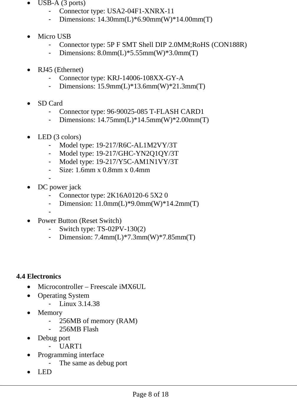
![Page 11 of 18 CSF key: This key is a subordinate key of the SRK key, and is used to verify the CSF data. CSF (Command Sequence File) is a binary data structure interpreted by the HAB to guide authentication operations. IMG key: This key is a subordinate key of the SRK key, and is used to verify the u-boot image. OSK key: This key is a subordinate key of the SRK key, and used to verify the OS image and the monitor daemon. APK key: This key is a subordinate key of the SRK key, and used to verify applications. 5.3 Core/Base Application Core/Base application is used to update the OS and/or add/update/remove application(s) through Ethernet. Interface: Ethernet, port 14000. Command & response format Command format: 02 + length (little endian, 4 bytes. Includes ALL from 02 to 03) + command (1 byte) + data + CRC (2 bytes) + 03 Note: The maximum length of a command should be less than 1200 bytes. Response format: 02 + length (little endian, 4 bytes. Includes ALL from 02 to 03) + Error-status (1 byte) + [data] + CRC (2 bytes) + 03 Error status codes: 0xE0: No error 0xE1: The command is invalid 0xE2: The command is error formatted. 0xE3: The file cannot be deleted. 0xE4: The file’s mode cannot be obtained. 0xE5: The file’s mode cannot be changed. 0xE6: The file cannot be created. 0xE7: The file cannot be written. 0xE8: The authentication failed. 0xE9: The command’s sequence is error. 0xEA : The file is too large. 0xEB : The directory cannot be created. 0xEC : The directory exists already. 0xED : The file exists already. Commands](https://usermanual.wiki/ID-TECH/IDCL-51/User-Guide-3029000-Page-11.png)
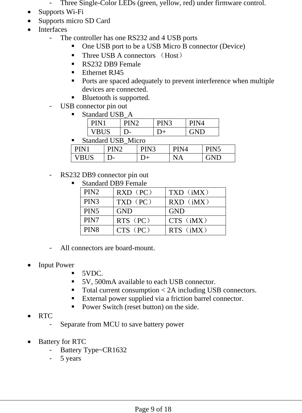
![Page 12 of 18 Get version of this application Command: 02 09 00 00 00 01 34 bf 03 Response: Error status [NULL-terminated version string] Add/Update application Command: 02 length 02 sequence (little endian, 4 bytes) path mode data CRC 03 <length>: The length must be less than 1200 bytes. <sequence>: The range is 0x000000 -0x00100000. The first package’s sequence must be 0x00000000, the next package’s sequence is the current package’s sequence plus 1. The last package’s sequence must be large than 0x00100000. <path>: A NULL-terminated string which defines the absolutely path of the file. The length of the path must be less than 200 bytes. <mode>: Defines the mode of the file. Bit0: 1 means can be executed, 0 means not. Bit1: 1 means can be written, 0 means not. Bit2: 1 means can be read, 0 means not. Response: Error status Note: This command will overwrite the existed file. To update OS, use the path “OS”. Remove application Command: 02 length 03 path CRC 03 <length>: The length must be less than 200 bytes. <path>: A NULL-terminated string which defines the absolutely path of the file. The length of the path must be less than 200 bytes. Response: Error status Get application mode Command: 02 length 05 path CRC 03 <length>: The length must be less than 200 bytes. <path>: A NULL-terminated string which defines the absolutely path of the file. The length of the path must be less than 200 bytes. Response: Error-status {mode}. Set application mode Command: 02 length 06 path mode CRC 03 <length>: The length must be less than 200 bytes. <path>: A NULL-terminated string which defines the absolutely path of the file. The length of the path must be less than 200 bytes. <mode>: Defines the mode of the file. Bit0: 1 means can be executed, 0 means not. Bit1: 1 means can be written, 0 means not. Bit2: 1 means can be read, 0 means not. Response: Error status](https://usermanual.wiki/ID-TECH/IDCL-51/User-Guide-3029000-Page-12.png)
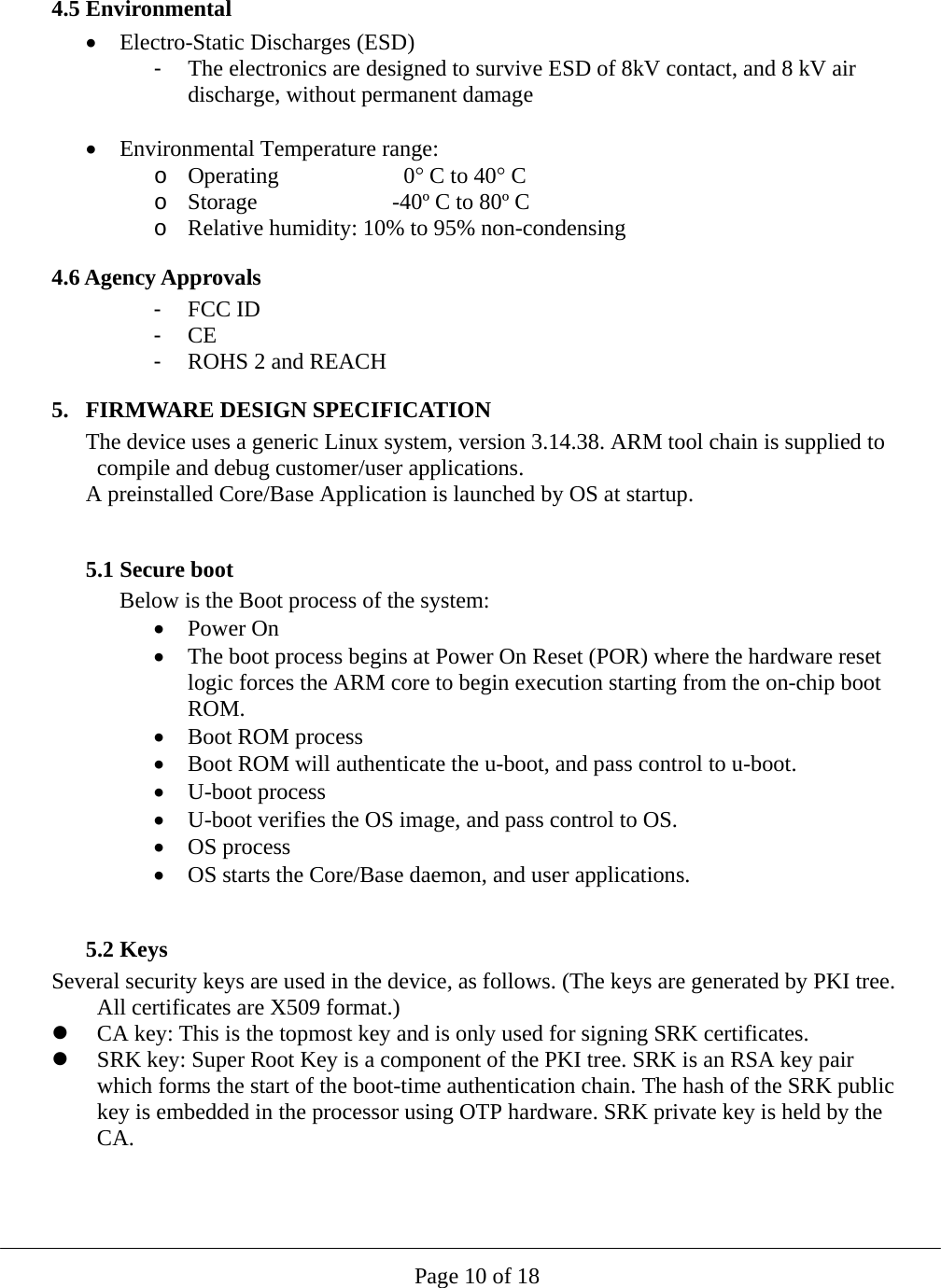
![Page 13 of 18 Add directory Command: 02 length 07 path mode CRC 03 <length>: The length must be less than 200 bytes. <path>: A NULL-terminated string which defines the absolutely path of the directory. The length of the path must be less than 200 bytes. <mode>: Defines the mode of the directory. Bit0: 1 means can be executed, 0 means not. Bit1: 1 means can be written, 0 means not. Bit2: 1 means can be read, 0 means not. Response: Error status Reboot Command: 02 09 00 00 00 0A e7 01 03 Response: Error status Get system version Command: 02 09 00 00 00 31 B7 8E 03 Response: Error status [NULL-terminated version string] Get serial number Command: 02 09 00 00 00 32 2C BC 03 Response: Error status [NULL-terminated serial number string] 5.4 Test Application This application is used for manufacturing, and if present, maybe deleted by user. It is used for basic diagnostic testing. This embedded application uses the RS232 port to communicate with the host. The parameters are: 115200, 8, N, 1. This embedded application listens for commands from the host (or external device) and sends back the corresponding responses. The commands and responses are all in ID TECH NGA format, which is STX (02) + LengthLSB + LengthMSB + Command + LRC (XOR of command bytes) + Sum (8-bit sum of command bytes) + ETX (03) 5.5 Command set (RS232 Test App) Ping It’s used to verify the accessibility of the device. Command: 18 Response: 06](https://usermanual.wiki/ID-TECH/IDCL-51/User-Guide-3029000-Page-13.png)