Users Manual

80144501-001
AC100
User Manual
Rev. A
06/03/2016

Page 2 of 18
Copyright 2016, International Technologies and Systems Corporation. All rights reserved.
ID TECH
10721 Walker Street
Cypress, CA 90630
USA
This document, as well as the hardware and software it describes, is furnished under license
and may only be used in accordance with the terms of such license. The content of this paper is
furnished for informational use, subject to change without notice, and not to be construed as a
commitment by ID TECH. While reasonable efforts have been made to ensure accuracy and
timeliness of information, ID TECH assumes no responsibility or liability for any unintentional
errors or inaccuracies that may appear in this document.
Except as permitted by such license, no part of this publication may be reproduced or
transmitted by electronic, mechanical, recorded, or any other method, or translated into
another language or language form without the express written consent of ID TECH.
ID TECH is a registered trademark of International Technologies and Systems Corporation.
Value through Innovation is a trademark of International Technologies and Systems
Corporation. Other trademarks are the property of the respective owner(s).
Warranty Disclaimer: The services and hardware are provided "as is" and "as-available," and the
use of these services and hardware are at the user’s own risk. ID TECH does not make, and
hereby disclaims, any and all other express or implied warranties, including, but not limited to
warranties of merchantability, title, fitness for a particular purpose, and any warranties arising
from any course of dealing, usage, or trade practice. Unless elsewhere specified, ID TECH does
not warrant that the services or hardware described here will be uninterrupted, error-free, or
completely secure.
Page 3 of 18
FCC Regulatory Compliance
Notices Class B Equipment
This equipment has been tested and found to comply with the limits for a Class B digital device
pursuant to Part 15 of the FCC Rules. These limits are designed to provide reasonable protection
against harmful interference in a residential installation. This equipment generates, uses, and can
radiate radio frequency energy and, if not installed and used in accordance with the instructions, may
cause harmful interference to radio communications. However, there is no guarantee that interference
will not occur in a particular installation. This device complies with part 15 of the FCC rules. Operation
is subject to two conditions: (1) This device may not cause harmful interference, and (2) this device
must accept any interference received, including interference that may cause undesired operation.
If this equipment does cause harmful interference to radio or television reception, which can be
determined by turning the equipment off and on, the user is encouraged to try and correct the
interference by one or more of the following measures:
Reorient or relocate the receiving antenna.
Increase the separation between the equipment and the receiver.
Connect the equipment into an outlet on a circuit different from that to which the receiver is
connected.
Consult the dealer or an experienced radio/TV technician for help.
Changes or modifications to the ID TECH AC100 not expressly approved by ID TECH could void
the user's authority to operate the AC100.
IC Compliance Warning
Operation is subject to two conditions: (1) This device may not cause harmful interference, and (2)
this device must accept any interference received, including interference that may cause undesired
operation.
Cautions and Warnings
Caution: The ID TECH AC100 should be mounted 1-2 feet away from other AC100
units. Can be adjusted based on lane setup.
Caution: Danger of Explosion if battery is incorrectly replaced. Replace only with
same or equivalent type recommended by the manufacturer. Discard used batteries
according to the manufacturer’s instructions.
Warnin
g
: Avoid close proximity to radio transmitters which may reduce the ability of
the device to transmit/receive data.

Page 4 of 18
Table of Content
1.Introduction ..................................................................................................................... 5
2.Product Configurations .................................................................................................... 5
3.Features............................................................................................................................ 5
4.MECHANICAL DESIGN SPECIFICATION ................................................................. 5
4.1 Physical Size & Look........................................................................................................ 5
4.2 Body Description .............................................................................................................. 7
4.3 Connectors ........................................................................................................................ 7
4.4 Electronics ......................................................................................................................... 8
4.5 Environmental ................................................................................................................. 10
4.6 Agency Approvals ........................................................................................................... 10
5.FIRMWARE DESIGN SPECIFICATION .................................................................... 10
5.1 Secure boot...................................................................................................................... 10
5.2 Keys ................................................................................................................................ 10
5.3 Core/Base Application .................................................................................................... 11
5.4 Test Application .............................................................................................................. 13
5.5 Command set (RS232 Test App) ..................................................................................... 13
Caution .................................................................................................................................... 18

Page 5 of 18
1. Introduction
This document outlines the mechanical, electrical, and connectivity features of the ID TECH
AC100 controller, a Linux-based application deployment platform and connectivity solution
for users of ID TECH payment peripherals. The AC100 is designed to allow deployment of a
wide range of secure payment apps while easing EMV L3 certification requirements.
2. Product Configurations
IDCL-51 AC100; Desktop
3. Features
Linux Operating System (3.14.38)
Full development tool chain to allow customers to edit, compile, and debug signed,
secure payment apps
256MB of Flash memory
256MB RAM
Micro SD Card storage
Multicolor status LED
Support for Wi-Fi and Ethernet
Supports Real Time Clock
USB type A (three ports) and Micro USB (one port)
RS232 interface
Reset button
4. MECHANICAL DESIGN SPECIFICATION
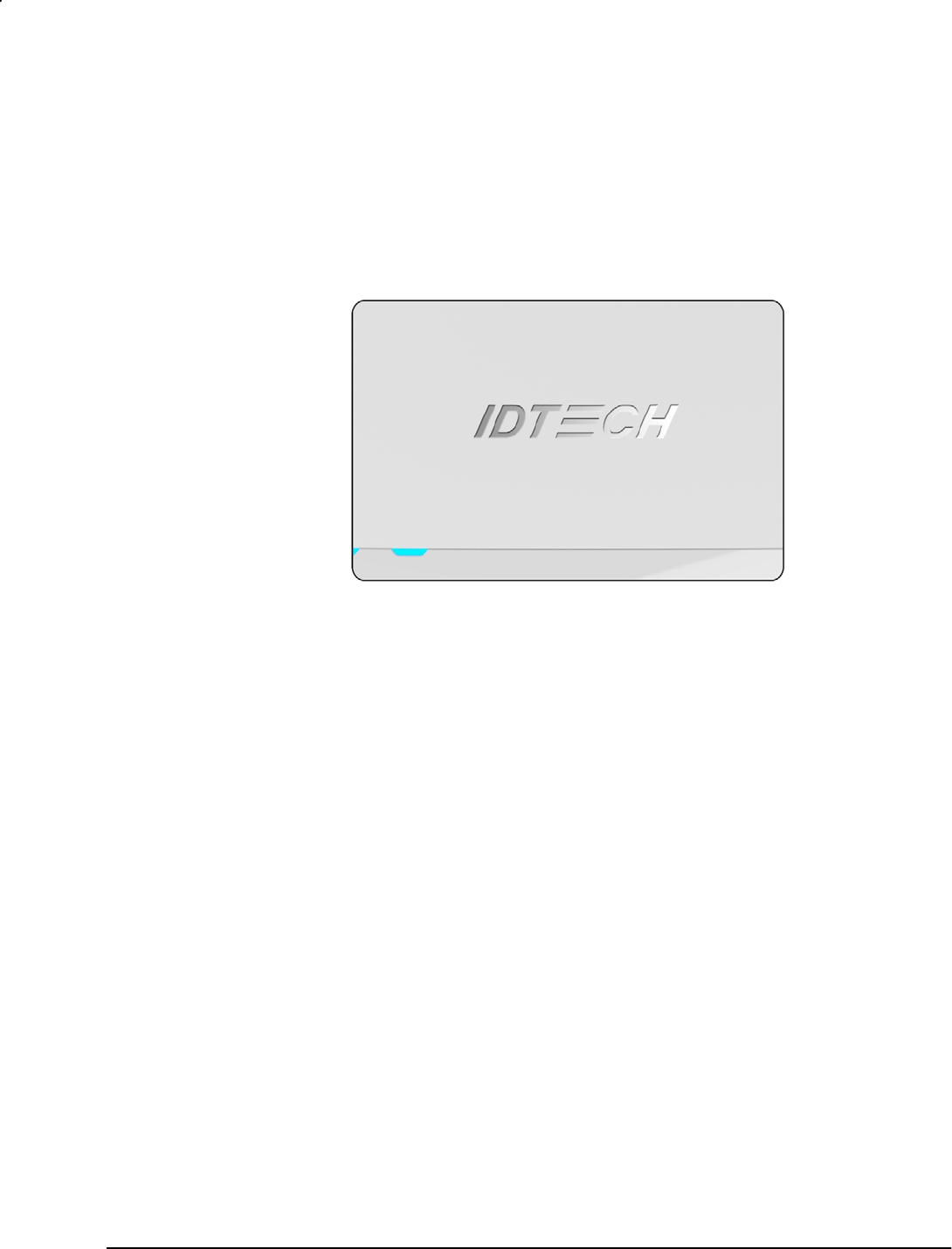
4.1 Physical Size & Look
Exterior:
- Unit comes in a plastic enclosure, white on the top and Pantone 2766U blue
on the bottom.
- Rubberized feet prevent movement when unit is placed on a counter
- Removable plastic cover (held by captive screw) for SD-card access.
- Mounting: two Nut3.0 attach points on the bottom for customer use.
Size and Weight
- Size: 140mm(L) x 86.0mm(W) x 30.0mm(H)
- Weight: 150g
Page 6 of 18
Top view:
Logo (IDTECH)
Surface: High Polish
Top Housing
Color: White
Surface: MT11006
LED-pipe
Color: Transparent
Surface: Polish
Page 7 of 18
4.2 Body Description
Housing
- Material: Polycarbonate/ABS resin.
- Wall thickness: 2.5mm.
Label
- Material: Lbl;Z-Ultimate;3000 White; 38mmx21mm;5570-R.
- Contents:
Model Number: IDCL-51
Serial Number: To comply WI 7.5.1-8.
Assembled in XXX (country of origin)
Revision
Bar Code: Code 128
MAC (12 hex digit)
FCC ID
CE mark
Circuit board
- Material: FR-4
- Dimension: 128.00mm(L)*61.00mm(W)*1.60mm(T)
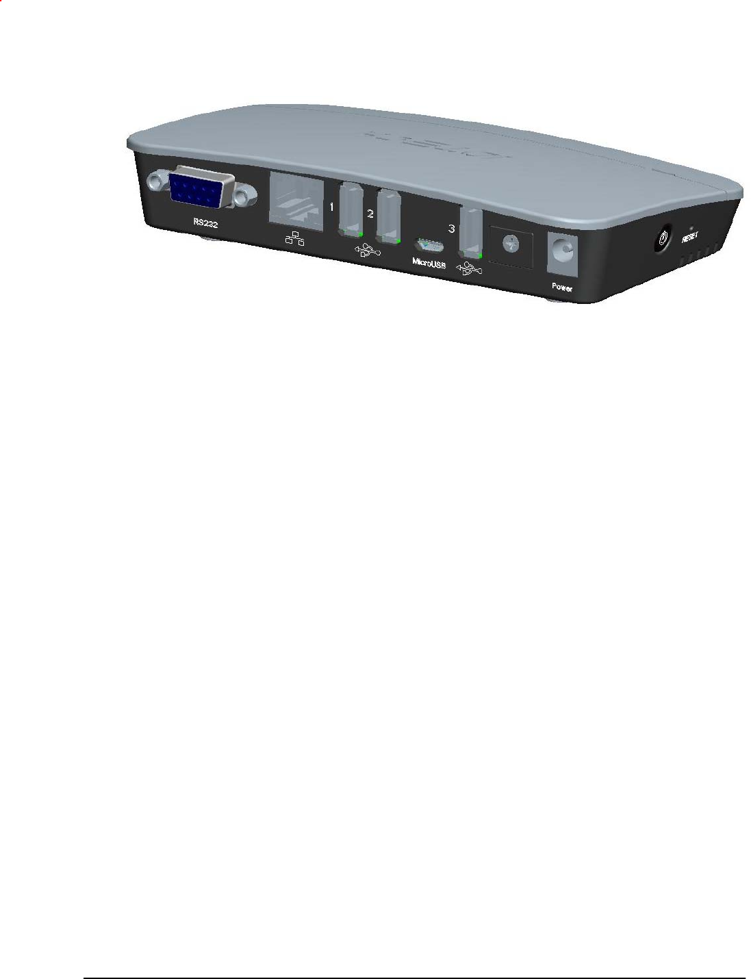
4.3 Connectors
RS232
- Connector type: ENG_CD_1734354_A1
- Dimensions: 30.8mm(L)*12.5mm(W)*18.4mm(T)
Reset
b
utton
USB
p
ort
(
1 of 3
)
Power connection
MicroUSB port
SD stora
g
e access
Ethernet
RS232

Page 8 of 18
USB-A (3 ports)
- Connector type: USA2-04F1-XNRX-11
- Dimensions: 14.30mm(L)*6.90mm(W)*14.00mm(T)
Micro USB
- Connector type: 5P F SMT Shell DIP 2.0MM;RoHS (CON188R)
- Dimensions: 8.0mm(L)*5.55mm(W)*3.0mm(T)
RJ45 (Ethernet)
- Connector type: KRJ-14006-108XX-GY-A
- Dimensions: 15.9mm(L)*13.6mm(W)*21.3mm(T)
SD Card
- Connector type: 96-90025-085 T-FLASH CARD1
- Dimensions: 14.75mm(L)*14.5mm(W)*2.00mm(T)
LED (3 colors)
- Model type: 19-217/R6C-AL1M2VY/3T
- Model type: 19-217/GHC-YN2Q1QY/3T
- Model type: 19-217/Y5C-AM1N1VY/3T
- Size: 1.6mm x 0.8mm x 0.4mm
-
DC power jack
- Connector type: 2K16A0120-6 5X2 0
- Dimension: 11.0mm(L)*9.0mm(W)*14.2mm(T)
-
Power Button (Reset Switch)
- Switch type: TS-02PV-130(2)
- Dimension: 7.4mm(L)*7.3mm(W)*7.85mm(T)
4.4 Electronics
Microcontroller – Freescale iMX6UL
Operating System
- Linux 3.14.38
Memory
- 256MB of memory (RAM)
- 256MB Flash
Debug port
- UART1
Programming interface
- The same as debug port
LED
Page 9 of 18
- Three Single-Color LEDs (green, yellow, red) under firmware control.
Supports Wi-Fi
Supports micro SD Card
Interfaces
- The controller has one RS232 and 4 USB ports
One USB port to be a USB Micro B connector (Device)
Three USB A connectors (Host)
RS232 DB9 Female
Ethernet RJ45
Ports are spaced adequately to prevent interference when multiple
devices are connected.
Bluetooth is supported.
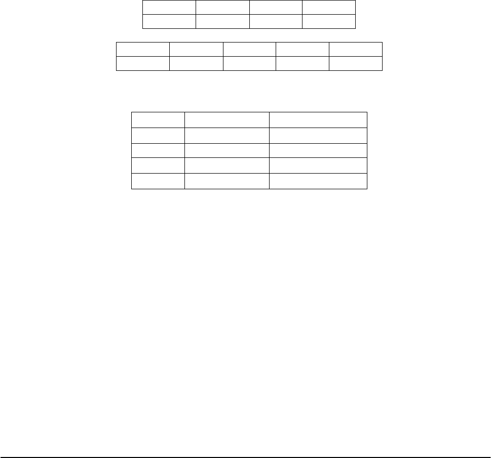
- USB connector pin out
Standard USB_A
PIN1 PIN2 PIN3 PIN4
VBUS D- D+ GND
Standard USB_Micro
PIN1 PIN2 PIN3 PIN4 PIN5
VBUS D- D+ NA GND
- RS232 DB9 connector pin out
Standard DB9 Female
PIN2 RXD(PC) TXD(iMX)
PIN3 TXD(PC) RXD(iMX)
PIN5 GND GND
PIN7 RTS(PC) CTS(iMX)
PIN8 CTS(PC) RTS(iMX)
- All connectors are board-mount.
Input Power
5VDC.
5V, 500mA available to each USB connector.
Total current consumption < 2A including USB connectors.
External power supplied via a friction barrel connector.
Power Switch (reset button) on the side.
RTC
- Separate from MCU to save battery power
Battery for RTC
- Battery Type~CR1632
- 5 years

Page 10 of 18
4.5 Environmental
Electro-Static Discharges (ESD)
- The electronics are designed to survive ESD of 8kV contact, and 8 kV air
discharge, without permanent damage
Environmental Temperature range:
o Operating 0 C to 40 C
o Storage -40º C to 80º C
o Relative humidity: 10% to 95% non-condensing
4.6 Agency Approvals
- FCC ID
- CE
- ROHS 2 and REACH
5. FIRMWARE DESIGN SPECIFICATION
The device uses a generic Linux system, version 3.14.38. ARM tool chain is supplied to
compile and debug customer/user applications.
A preinstalled Core/Base Application is launched by OS at startup.
5.1 Secure boot
Below is the Boot process of the system:
Power On
The boot process begins at Power On Reset (POR) where the hardware reset
logic forces the ARM core to begin execution starting from the on-chip boot
ROM.
Boot ROM process
Boot ROM will authenticate the u-boot, and pass control to u-boot.
U-boot process
U-boot verifies the OS image, and pass control to OS.
OS process
OS starts the Core/Base daemon, and user applications.
5.2 Keys
Several security keys are used in the device, as follows. (The keys are generated by PKI tree.
All certificates are X509 format.)
CA key: This is the topmost key and is only used for signing SRK certificates.
SRK key: Super Root Key is a component of the PKI tree. SRK is an RSA key pair
which forms the start of the boot-time authentication chain. The hash of the SRK public
key is embedded in the processor using OTP hardware. SRK private key is held by the
CA.

Page 11 of 18
CSF key: This key is a subordinate key of the SRK key, and is used to verify the CSF
data. CSF (Command Sequence File) is a binary data structure interpreted by the HAB
to guide authentication operations.
IMG key: This key is a subordinate key of the SRK key, and is used to verify the u-boot
image.
OSK key: This key is a subordinate key of the SRK key, and used to verify the OS
image and the monitor daemon.
APK key: This key is a subordinate key of the SRK key, and used to verify applications.
5.3 Core/Base Application
Core/Base application is used to update the OS and/or add/update/remove application(s)
through Ethernet.
Interface: Ethernet, port 14000.
Command & response format
Command format:
02 + length (little endian, 4 bytes. Includes ALL from 02 to 03) +
command (1 byte) + data + CRC (2 bytes) + 03
Note: The maximum length of a command should be less than 1200 bytes.
Response format:
02 + length (little endian, 4 bytes. Includes ALL from 02 to 03) +
Error-status (1 byte) + [data] + CRC (2 bytes) + 03
Error status codes:
0xE0: No error
0xE1: The command is invalid
0xE2: The command is error formatted.
0xE3: The file cannot be deleted.
0xE4: The file’s mode cannot be obtained.
0xE5: The file’s mode cannot be changed.
0xE6: The file cannot be created.
0xE7: The file cannot be written.
0xE8: The authentication failed.
0xE9: The command’s sequence is error.
0xEA : The file is too large.
0xEB : The directory cannot be created.
0xEC : The directory exists already.
0xED : The file exists already.
Commands

Page 12 of 18
Get version of this application
Command: 02 09 00 00 00 01 34 bf 03
Response: Error status [NULL-terminated version string]
Add/Update application
Command: 02 length 02 sequence (little endian, 4 bytes) path mode data CRC 03
<length>: The length must be less than 1200 bytes.
<sequence>: The range is 0x000000 -0x00100000.
The first package’s sequence must be 0x00000000, the next package’s sequence is the
current package’s sequence plus 1. The last package’s sequence must be large than
0x00100000.
<path>: A NULL-terminated string which defines the absolutely path of the file. The
length of the path must be less than 200 bytes.
<mode>: Defines the mode of the file.
Bit0: 1 means can be executed, 0 means not.
Bit1: 1 means can be written, 0 means not.
Bit2: 1 means can be read, 0 means not.
Response: Error status
Note:
This command will overwrite the existed file.
To update OS, use the path “OS”.
Remove application
Command: 02 length 03 path CRC 03
<length>: The length must be less than 200 bytes.
<path>: A NULL-terminated string which defines the absolutely path of the file. The
length of the path must be less than 200 bytes.
Response: Error status
Get application mode
Command: 02 length 05 path CRC 03
<length>: The length must be less than 200 bytes.
<path>: A NULL-terminated string which defines the absolutely path of the file. The
length of the path must be less than 200 bytes.
Response: Error-status {mode}.
Set application mode
Command: 02 length 06 path mode CRC 03
<length>: The length must be less than 200 bytes.
<path>: A NULL-terminated string which defines the absolutely path of the file. The
length of the path must be less than 200 bytes.
<mode>: Defines the mode of the file.
Bit0: 1 means can be executed, 0 means not.
Bit1: 1 means can be written, 0 means not.
Bit2: 1 means can be read, 0 means not.
Response: Error status

Page 13 of 18
Add directory
Command: 02 length 07 path mode CRC 03
<length>: The length must be less than 200 bytes.
<path>: A NULL-terminated string which defines the absolutely path of the directory.
The length of the path must be less than 200 bytes.
<mode>: Defines the mode of the directory.
Bit0: 1 means can be executed, 0 means not.
Bit1: 1 means can be written, 0 means not.
Bit2: 1 means can be read, 0 means not.
Response: Error status
Reboot
Command: 02 09 00 00 00 0A e7 01 03
Response: Error status
Get system version
Command: 02 09 00 00 00 31 B7 8E 03
Response: Error status [NULL-terminated version string]
Get serial number
Command: 02 09 00 00 00 32 2C BC 03
Response: Error status [NULL-terminated serial number string]
5.4 Test Application
This application is used for manufacturing, and if present, maybe deleted by user. It is used
for basic diagnostic testing.
This embedded application uses the RS232 port to communicate with the host. The
parameters are: 115200, 8, N, 1.
This embedded application listens for commands from the host (or external device) and sends
back the corresponding responses. The commands and responses are all in ID TECH
NGA format, which is
STX (02) + LengthLSB + LengthMSB + Command + LRC (XOR of command bytes)
+ Sum (8-bit sum of command bytes) + ETX (03)
5.5 Command set (RS232 Test App)
Ping
It’s used to verify the accessibility of the device.
Command: 18
Response: 06

Page 14 of 18
Get Version
Get the test application’s version.
Command: 01
Response: NULL-terminated string.
Set Serial Number
Set device's serial number.
Command: 02 <Serial Number>
<Serial Number>: NULL-terminated S/N
Response: 06 if succeeded, or E1 if failed.
Get Serial Number
Get device's serial number.
Command: 03
Response: Device's serial number if succeeded, or E1 if failed.
LED test
Control the ON or OFF of three LEDs.
Command: 92 <LED mask> <On/Off>
<LED mask>: Specify which LED to control.
Bit 0: RED. Value 1 means controlled by <On/Off>, 0 no influence.
Bit 1: GREEN. Value 1 means controlled by <On/Off>, 0 no influence.
Bit 2: YELLOW. Value 1 means controlled by <On/Off>, 0 no influence.
<On/Off>: This is effective only corresponding bit in <LED> is set.
Bit 0: 1 RED On, 0 RED Off.
Bit 1: 1 GREEN On, 0 GREEN Off.
Bit 2: 1 YELLOW On, 0 YELLOW Off.
Response: 06
SD port test
Get a specified file’s content from the SD card’s root directory.
Command: 93
Response: The file’s content if succeeded, or E1 if failed.
Note: This command will take about 2 seconds.
Network port test
Test if the gateway is accessibility through Ethernet.
Command: 94 <Gateway’s address>
<Gateway’s address>: 4 bytes IP4 address.
Response: 06 if succeeded, or E1 if failed.
Note: This command will take about 3 seconds.
USB host ports test
Get a specified file’s content from the USB card’s root directory.

Page 15 of 18
Command: 95
Response: The file’s content if succeeded, or E1 if failed.
Note: This command will take about 2 seconds.
Wi-Fi test
Test if the gateway is accessibility through Wi-Fi.
Command: 96 <Gateway’s address> <AP name> <AP password>
<Gateway’s address>: 4 bytes IP4 address.
<AP name>: NULL-terminated AP’s name.
<AP password>: NULL-terminated AP’s password.
Response: 06 if succeeded, or E1 if failed.
Note: This command will take about 20 seconds.
Blue-Tooth test
Test if the blue-tooth is accessible.
Command: 97
Response: The Bluetooth devices’ names nearby if succeeded, or E1 if failed.
Note: This command will take about 40 seconds.
Set RTC
Set the RTC.
Command: 98 +<DateTime>
<DateTime> : <year> <month>-<date> <hour>:<minute>:<second>
<year> : 4 bytes
<month> : 2 bytes
<date> : 2 bytes
<hour> : 2 bytes
<minute> : 2 bytes
<second> : 2 bytes
For example, if the date is “2016-7-27 11:06:04”, the command body should be
“98 32 30 31 36 2D 30 37 2D 32 37 20 31 31 3A 30 36 3A 30 34”
Response: 06 if succeeded, or E1 if failed
Get RTC
Get the RTC.
Command: 99
Response: <DateTime> if succeeded, or E1 if failed
Reset Key test
Test the reset key. After receiving this command, the system will monitor the
key in 10 seconds, and then response the result.
Command: 9A
Response: 06 if the key is pressed, or E1 otherwise
Set MAC
This command will set the ethernet’s MAC address.

Page 16 of 18
Command: 9B <MAC Address>
<MAC Address>: the length is 17 bytes. The format is xx:xx:xx:xx:xx:xx. eg.
31 31 3A 32 32 3A 33 33 3A 34 34 3A 35 35 3A 36 36 means 11:22:33:44:55:66.
Response: 06 if the MAC address is valid, or E1 otherwise
Get MAC
This command will get the ethernet’s MAC address.
Command: 9C
Response: 06 <MAC Address> if the MAC address is exist, or E1 otherwise.

Page 17 of 18
Revision History
Revision Description and Reason for Change Date
50 First draft. 01/05/16
A Edits for style and content. Formatting. Deletion of inapplicable
content.
6/3/2016
(KT)

Page 18 of 18
Caution
CE1177
1. Adapter shall be installed near the equipment and shall be easily accessible.
2. Avoid exposing your mobile phone to extreme hot or cold temperatures. The temperature
range for using the phone is 0°C~40°C.
3. This equipment is in compliance with the essential requirements and other relevant provisions
of Directive 1999/5/EC.