ID TECH VEND3 Contactless Credit Card Reader User Manual Users manual
ID TECH Contactless Credit Card Reader Users manual
UserManual.wiki
>
ID TECH
>
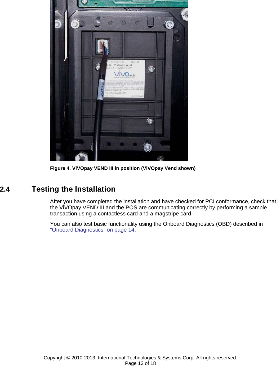
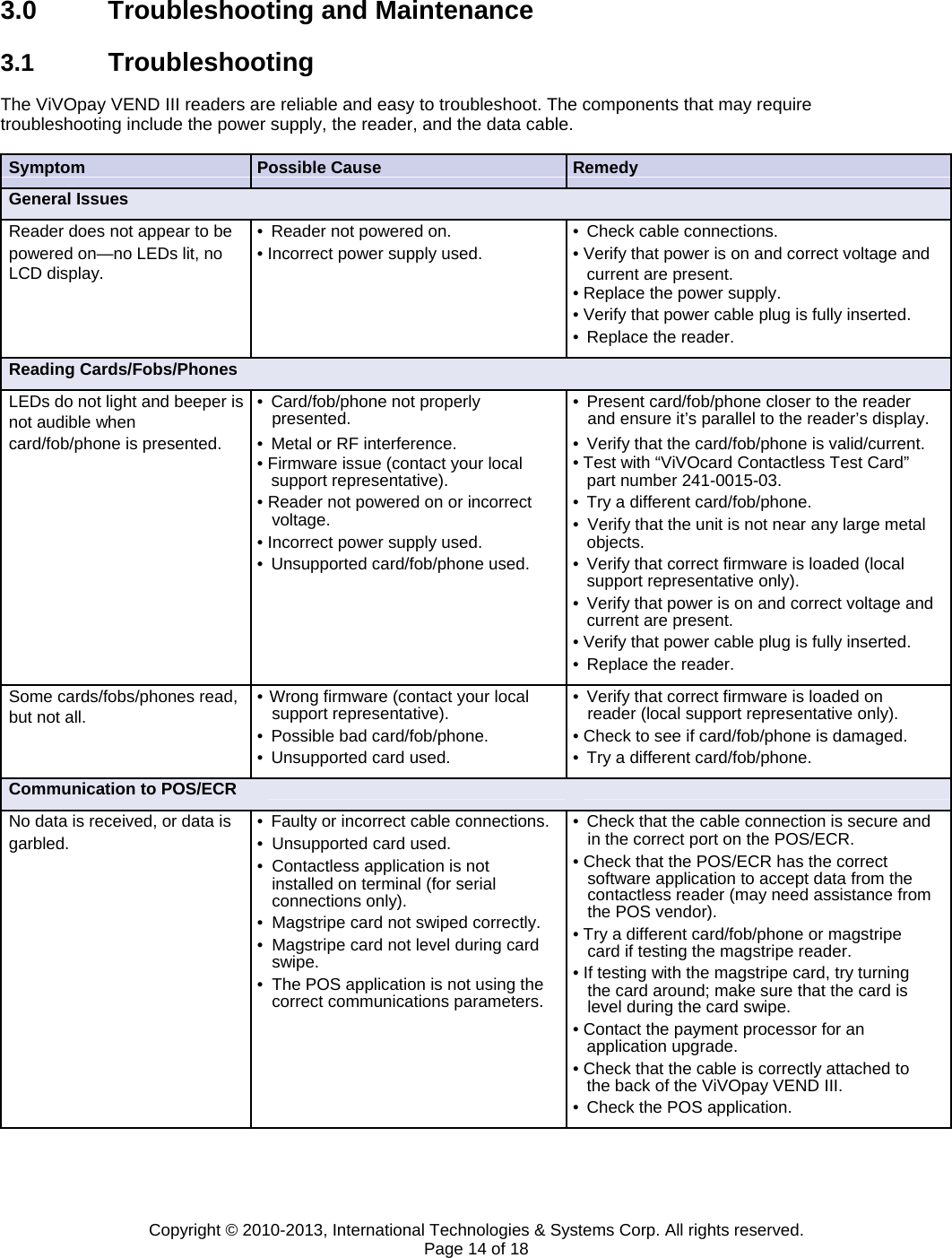
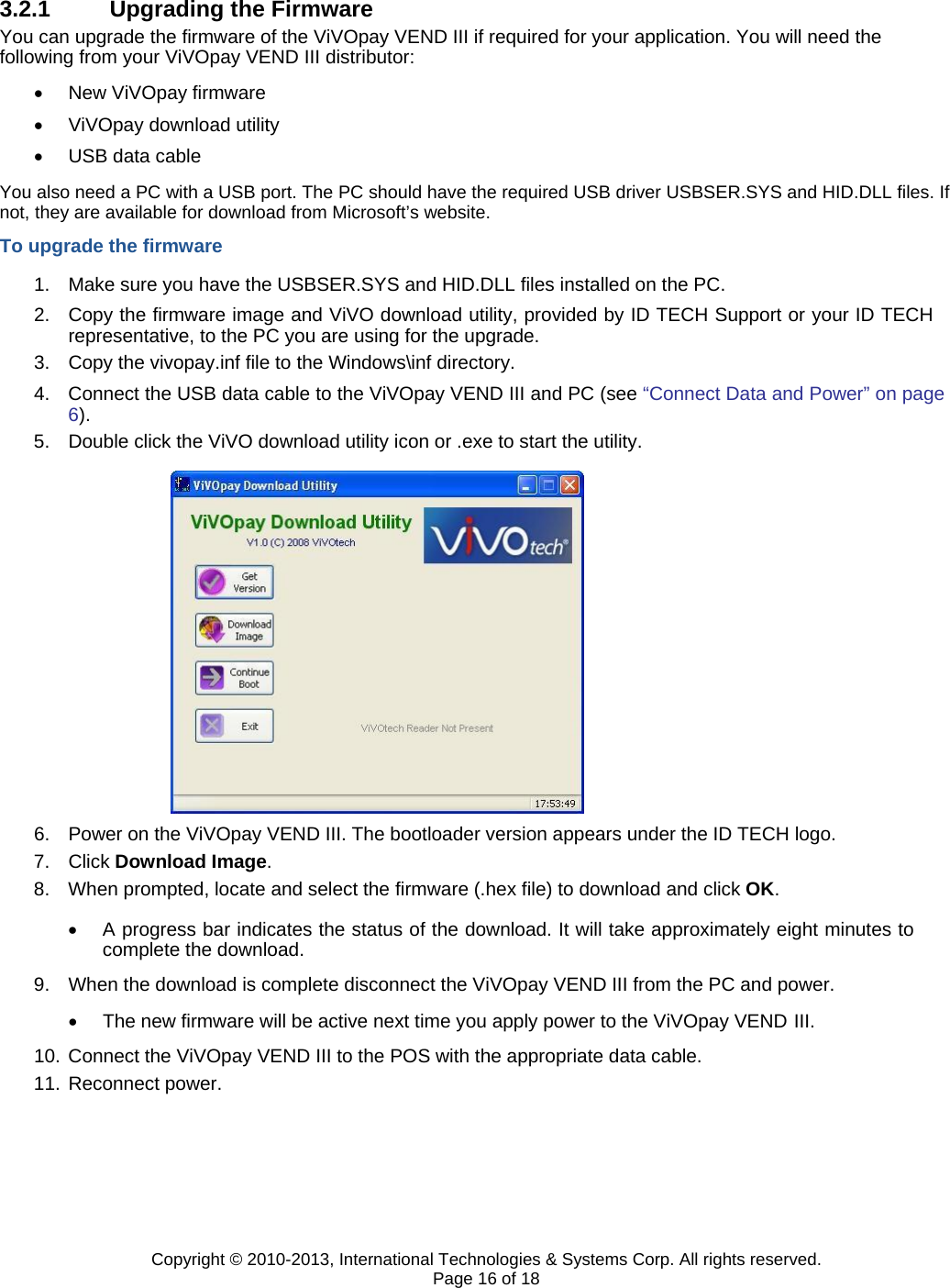
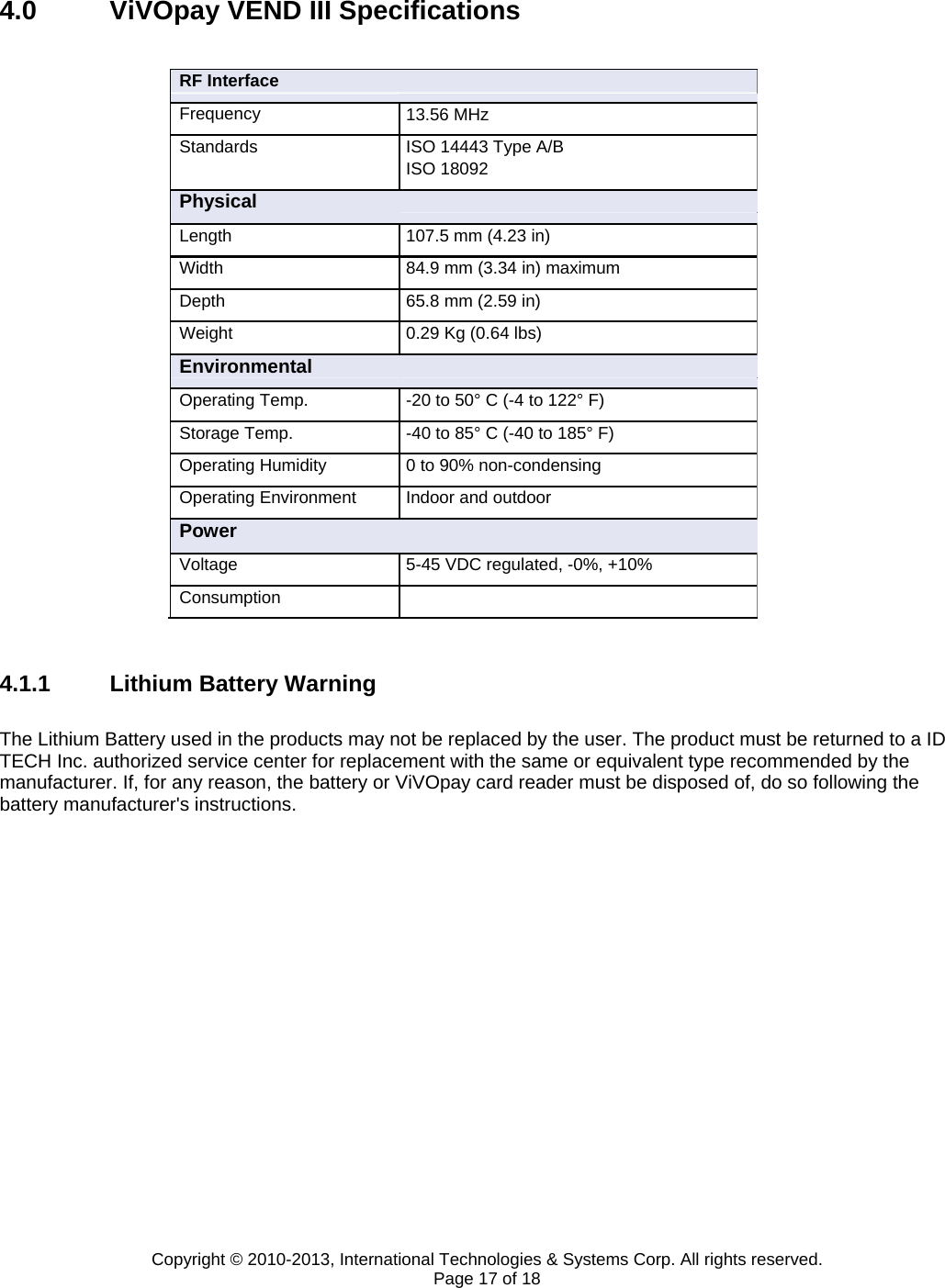
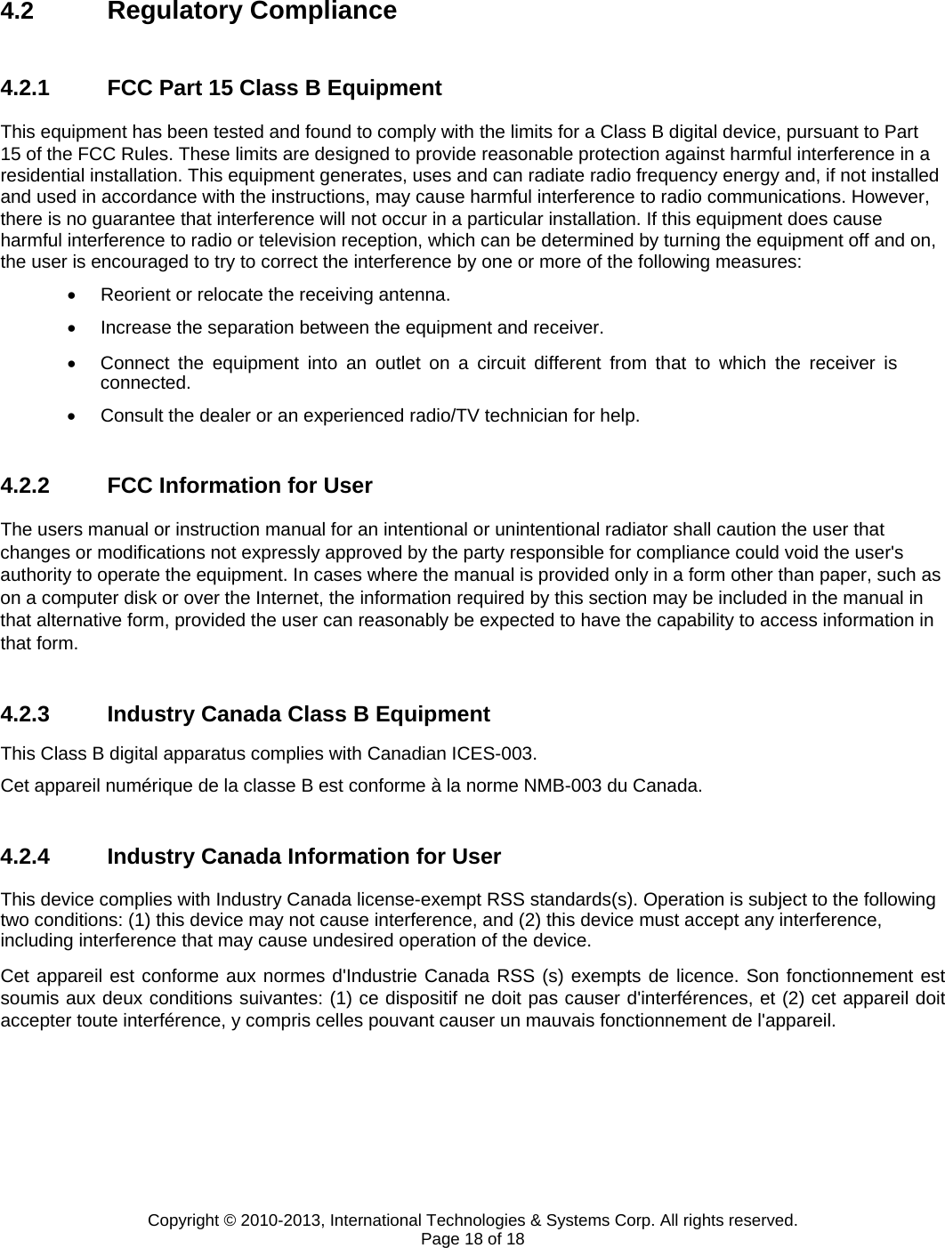
VEND3 User Manual
Users manual
Navigation menu
Upload a User Manual
Namespaces
Wiki Guide
HTML
PDF
Info
Views
User Manual
Discussion / Help
Navigation