ID TECH VEND3 Contactless Credit Card Reader User Manual Users manual
ID TECH Contactless Credit Card Reader Users manual
ID TECH >
Users manual

Vend III User Guide
80135501-001
10-25-2013
Copyright © 2010-2013, International Technologies & Systems Corp. All rights reserved.
Page 1 of 18
Copyright © 2010-2013, International Technologies & Systems Corp. All rights reserved.
Page 2 of 18
Copyright© 2013, International Technologies and Systems Corporation. All rights reserved.
ID TECH .
10721 Walker Street
Cypress CA 90630
USA
This document, as well as the hardware and software it describes, is furnished under license and may only be
used in accordance with the terms of such license. The content of this paper is furnished for informational use,
subject to change without notice, and not to be construed as a commitment by ID TECH. ID TECH assumes no
responsibility or liability for any errors or inaccuracies that may appear in this document.
Except as permitted by such license, no part of this publication may be reproduced or transmitted by electronic,
mechanical, recorded, or any other method, or translated into another language or language form without the
express written consent of ID TECH. ID TECH is a registered trademark of International Technologies and
Systems Corporation. ViVOpay and Value through Innovation are trademarks of International Technologies and
Systems Corporation. Other trademarks are the property of the respective owner.
Warranty Disclaimer: The services and hardware are provided "as is" and "as-available," and the use of these ser-
vices and hardware is at the user’s own risk. ID TECH does not make, and hereby disclaims, any and all other
express or implied warranties, including, but not limited to warranties of merchantability, title, fitness for a particular
purpose, and any warranties arising from any course of dealing, usage, or trade practice. ID TECH does not war-
rant that the services or hardware will be uninterrupted, error-free, or completely secure.
October 2013
Copyright © 2010-2013, International Technologies & Systems Corp. All rights reserved.
Page 3 of 18
Table of Contents
Table of Contents
1.0 Getting Started ………….…………………………………………….4
1.1 Overview .………………………………………………………………………………………...4
1.1.1 Features ………….……………………………………………………………………...….4
1.2 Unpacking the ViVOpay Vend III .……………………………………………………………..5
2.0 Installing the ViVOpay Vend III …………………………….………6
2.1 Overview ………………………………………………………………………………………...6
2.2 Site Planning ……………………………………………………………………………………6
2.2.1 Radio Frequency Interference .………………..…………………………………………6
2.2.2 User Access ……………………………………………..………………………………...6
2.3 Installing the ViVOpay VEND III ………………………………………………………………7
2.31. Connector and SAM Access .………………………………………..…………………...7
2.3.2 Install a SAM Card .………………………………………………………..……………....7
2.3.3 Connect Data and Power ..…………………………………………….…….……………8
2.3.4 Connect Ethernet .………………………………………………………..………………10
2.3.5 External Mount .…………..………………………………………………………………11
2.3.6 Internal Mount .………………………………………………………..………………….11
2.4 Testing the Installation .……………………………………………...……………………….13
3.0 Troubleshooting and Maintenance ……………………….……..14
3.1 Troubleshooting .………………………………………………………………………………14
3.1.1 Onboard Diagnostics .………………………….……………….………………………..15
3.2 Maintenance ………………………………………………...………………………………...15
3.2.1 Upgrading the Firmware .………………………………….…………………………….16
4.0 ViVOpay VEND III Specifications …………………………….…..17
4.1.1 Lithium Battery Warning .………………..……………………………………………….17
4.2 Regulatory Compliance .………………………………………………………………………18
4.2.1 FCC Part 15 Class B Equipment ..…………………………………………..…………..18
4.2.2 FCC Information for User .…………………………….………………….……………...18
4.2.3 Industry Canada Class B Equipment .…………………………………..……………...18
4.2.4 Industry Canada Information for User .……………………………..…………………..18
Copyright © 2010-2013, International Technologies & Systems Corp. All rights reserved.
Page 4 of 18
1.0 Getting Started
1.1 Overview
The ViVOpay VEND III seamlessly integrates with existing vending systems and fits into a standard bill changer
opening. The ViVOpay VEND III is an unattended NFC and contactless reader with Magnetic Stripe Reader,
contact EMV card reader, integrated display and function keys. This device features serial RS-232 and USB 2.0
communications to POS systems as well as an Ethernet port. The ViVOpay VEND III complies with ISO/IEC 18092
nd supports the full peer-to-peer NFC feature set.
a
V
iVOpay VEND III is certified for the following contactless payment applications:
EMVCo CCPS
MasterCard PayPass M/Chip
Visa payWave VCPS
American Express, ExpressPay
Discover DPAS
Mifare (Passthrough)
ISIS SmartTap
Google Wallet
ViVOpay VEND III also fully supports magnetic stripe applications.
This document assumes that users are familiar with their host POS systems and vending machines.
1.1.1 Features
The following features are supported:
ISO14443 type A/B and Mifare based contactless payment transactions
ISO 18092
Three-track magnetic stripe reader
Three SAM card slots
Contact card slot
10 Base-T Ethernet port
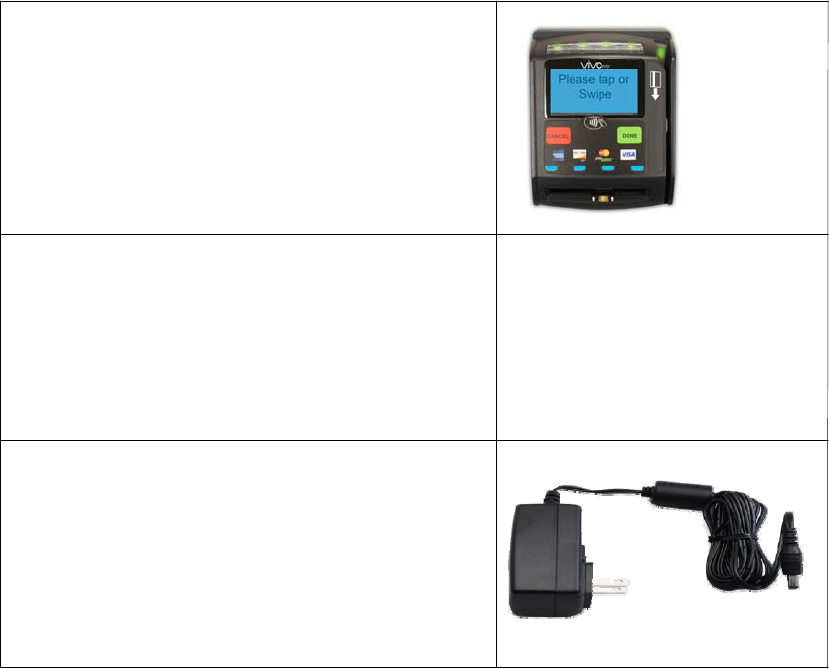
1.2 Unpacking the ViVOpay Vend III
The ViVOpay VEND III requires a data cable and a power supply. Verify that you have all the required
components for the installation.
ViVOpay VEND III
*XX designates variations of the base model.
Data and Power cables (varies by length)
• Serial Data Cable (P/N 220-2467-XX*)
• USB Data Cable (P/N 220-2466-XX*)
These cables are recommended and approved by
ID TECH to comply with FCC rules and regulations.
*XX designates cable length.
Copyright © 2010-2013, International Technologies & Systems Corp. All rights reserved.
Page 5 of 18
Power supply
• US/North America (P/N 140-2035-00)
• Europe (P/N 140-2035-01)
• United Kingdom (P/N 140-2035-02)
• Australia (P/N 140-2035-03)
This power supply is recommended and approved
by ID TECH to comply with FCC rules and
regulations.
Y
ou may also need the following:
Four M3 screws
If you want to secure the reader to a surface, you need four M3 screws of the appropriate length
(not supplied).
Contactless test card (P/N 241-0015-03)
T
he ID TECH data cables and power supply are specifically designed to meet FCC requirements.
Copyright © 2010-2013, International Technologies & Systems Corp. All rights reserved.
Page 6 of 18
2.0 Installing the ViVOpay Vend III
2.1 Overview
Before you connect and mount the ViVOpay VEND III, you should plan the installation to conform to PCI requirements
and minimize radio frequency interference. Once you have determined the location and mounting of the ViVOpay
VEND III, you can connect it to power and the control unit. Finally, you should test the ViVOpay VEND III to make sure
the installation is successful.
2.2 Site Planning
Environmental considerations affect how you install the ViVOpay VEND III. You should consider objects and
devices near the reader that may affect the performance of the contactless radio frequency antenna.
2.2.1 Radio Frequency Interference
To perform contactless transactions, the ViVOpay VEND III uses a radio frequency antenna. The range
(reading distance) and performance of the reader can be affected by other radio frequency emitters and
proximity to metal.
For best performance, adhere to the following guidelines:
Do not position the ViVOpay VEND III closer than 1 foot (30 cm) to other ViVOpay readers or other RF-
emitting devices (non-NFC). Some environments may require greater distances.
Do not position the ViVOpay VEND III near radio transmitters.
Avoid placing the ViVOpay VEND III on or near large metal objects.
2.2.2 User Access
The ViVOpay VEND III is design for unattended use. Is is important to consider the following factors when
lanning the location of the reader.
p
Clear visibility of the display
Anticipate the angles at which the user may be viewing the display to maximize visibility.
Make sure the user can easily reach the reader
Provide access to the reader to push buttons and tap or swipe cards.
No obstructions in the MSR swipe path
Make sure nothing is blocking the entrance or exit of a card passing through the MSR.
2.3 Installing the ViVOpay VEND III
T
his section describes how to install the ViVOpay VEND III. The basic steps are:
Install SAMs if required
Connect to power and POS
Mount
Test the installation
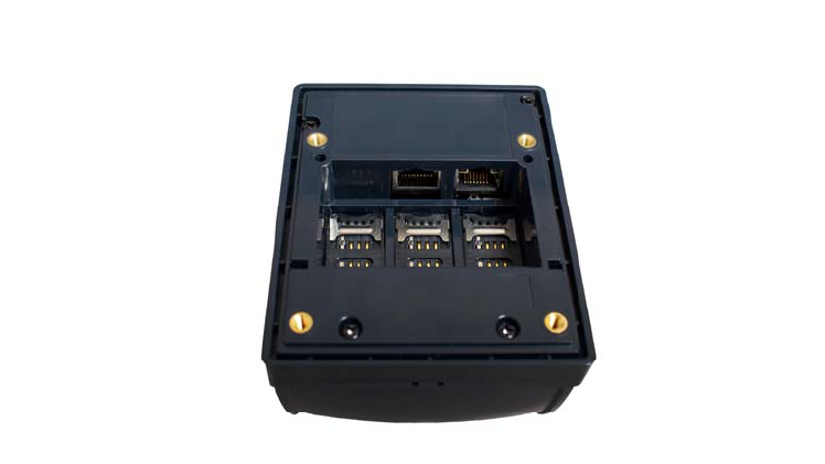
2.3.1 Connector and SAM Access
The ViVOpay VEND III connectors and SAM slots are on the bottom of the reader.
To access the connectors:
1. Turn over the ViVOpay VEND III so that the connectors and SAM slots are visible.
2.3.2 Install a SAM Card
All ViVOpay VEND III models have three SAM card slots in addition to one SoftSAM. Consequently, the physical
SAMs are labeled SAM 2 through SAM 4, left to right. If you are using a SAM card(s) in your application, insert the
AM card as described in the following steps.
S
Warning: Do not insert or remove a SAM card while the ViVOpay VEND III is powered. This will cause
permanent damage to the SAM card.
To install a SAM card:
1. Use your fingernail to slide the lock bar down, away from the connectors, and pull the SAM cage away
from the closed position. The cage hinges on the edge furthest from the connector ports.
Copyright © 2010-2013, International Technologies & Systems Corp. All rights reserved.
Page 7 of 18
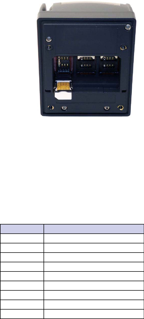
2. Insert the card with the contacts facing the bottom of the SAM cage. The cut corner of the SAM should be
positioned shown below.
3. Press the cage into the closed position. The cage will snap into place.
4. Slide the lock bar up, towards the connectors, to lock the SAM in position.
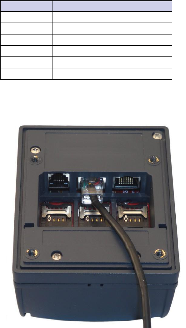
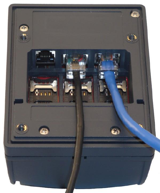
2.3.3 Connect Data and Power
There are connectors for Ethernet, data and power, and PIN pad in back of the ViVOpay VEND III. The
connections you need to make are dependant on your specific POS configuration and application. The power is
received on the data connector. The product is intended to be powered by a DC source from 5 VDC to 45 VDC;
this power source should comply with the Limited Power Source requirements (sub-clause 2.5 of UL/IEC 60950-1).
It is recommended to power the product with a LPS UL Listed/ Class 2 IEC certified DC power supply, output rated
Vdc, 0.67 A.
9
T
he pinouts for the POS side of the data cables are given in the tables below.
RS-232 (220-2467-0X)
DB9 Pin Number Description
1 No connect
2 RS-232 Tx
3 RS-232 Rx
4 No connect
5 GND
6 No connect
7 No connect
8 No connect
9 Power 5 - 45 VDC
Copyright © 2010-2013, International Technologies & Systems Corp. All rights reserved.
Page 8 of 18
USB (220-2367-0X)
USB Pin Number Description
1 VBus
2 Data - (DM)
3 Data + (DP)
4 GND
5 GND
6 Power 12 VDC
To connect data and power
1. Connect your data cable to the RS232/USB port.
Copyright © 2010-2013, International Technologies & Systems Corp. All rights reserved.
Page 9 of 18
2. Connect the other end to the host system. Refer to the pinouts given above if needed.
The ViVOpay VEND III displays the opening set of screens before it displays the Welcome screen.
T
he opening screens include:
Copyright screen
Firmware version screen
The reader should then display Welcome or Please present card or similar wording, depending upon the
pplication.
a
If the reader fails to power up, try reseating the power connector (or change to a different power outlet). For more
troubleshooting information, see “Troubleshooting” on page 13.
2.3.4 Connect Ethernet
To connect to Ethernet
1. Insert a CAT5 or better cable into the Ethernet port. (Note The TCP protocol stack is not supported in the
initial product release)
2. Connect the other end of the Ethernet cable to an Ethernet switch or hub.
Copyright © 2010-2013, International Technologies & Systems Corp. All rights reserved.
Page 10 of 18
2.3.5 External Mount
The ViVOpay VEND III can be mounted directly on a surface (external) or mounted from behind a surface
internal) using a flange bracket. Surface mounting requires the standoff and seal for effective weather proofing. (
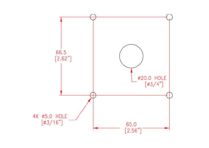
To mount externally
1. Drill four 5.0mm (3/16 inch) holes in the surface where the ViVOpay VEND III will be mounted. Use
the hole spacing shown in Figure 1.
Figure 1. Mounting hole dimensions
2. Drill a 20.0mm (3/4 inch) hole or cut an access hole large enough to pass an RJ50 connector in the center
of the area inside the mounting holes.
3. Position the ViVOpay VEND III over the mounting holes and use four M4 screws (not supplied)
long enough to secure the ViVOpay VEND III to the mounting surface.
2.3.6 Internal Mount
The ViVOpay VEND III can be supplied with a bracket designed to install the ViVOpay VEND III in the same
cation as a currency acceptance device.
lo
To mount internally
1. Disconnect power from the vending machine.
2. Open the vending machine to access the currency acceptor mounting locations.
3. Remove the currency acceptor or cover plate. Retain the fasteners for ViVOpay VEND III installation.
Copyright © 2010-2013, International Technologies & Systems Corp. All rights reserved.
Page 11 of 18
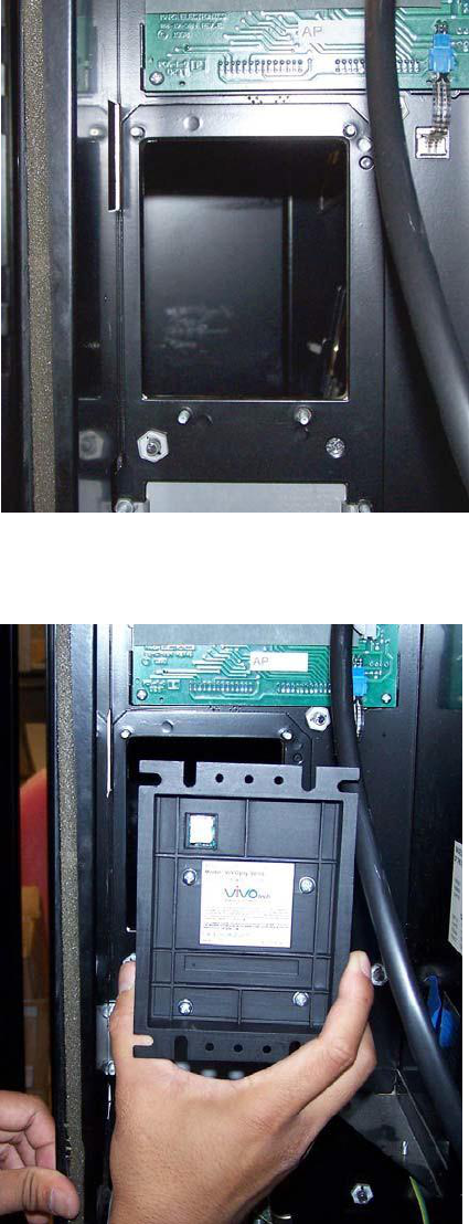
Figure 2. Currency acceptor removed
4. Insert ViVOpay VEND III with bracket from inside the vending machine.
Figure 3. Placing the reader (ViVOpay Vend shown)
5. Secure the ViVOpay VEND III with the fasteners from Step 3.
Copyright © 2010-2013, International Technologies & Systems Corp. All rights reserved.
Page 12 of 18
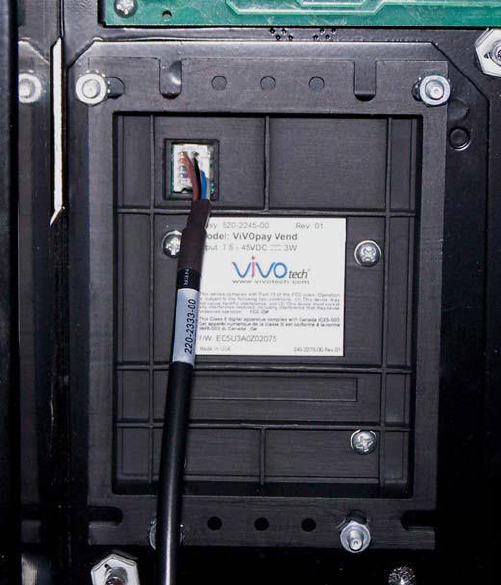
Figure 4. ViVOpay VEND III in position (ViVOpay Vend shown)
2.4 Testing the Installation
After you have completed the installation and have checked for PCI conformance, check that
the ViVOpay VEND III and the POS are communicating correctly by performing a sample
transaction using a contactless card and a magstripe card.
You can also test basic functionality using the Onboard Diagnostics (OBD) described in
“Onboard Diagnostics” on page 14.
Copyright © 2010-2013, International Technologies & Systems Corp. All rights reserved.
Page 13 of 18

Copyright © 2010-2013, International Technologies & Systems Corp. All rights reserved.
Page 14 of 18
3.0 Troubleshooting and Maintenance
3.1 Troubleshooting
The ViVOpay VEND III readers are reliable and easy to troubleshoot. The components that may require
troubleshooting include the power supply, the reader, and the data cable.
Symptom Possible Cause Remedy
General Issues
Reader does not appear to be • Reader not powered on. •Check cable connections.
powered on—no LEDs lit, no • Incorrect power supply used. • Verify that power is on and correct voltage and
LCD display. current are present.
• Replace the power supply.
• Verify that power cable plug is fully inserted.
•Replace the reader.
Reading Cards/Fobs/Phones
LEDs do not light and beeper is • Card/fob/phone not properly •Present card/fob/phone closer to the reader
presented. and ensure it’s parallel to the reader’s display.
not audible when
card/fob/phone is presented. • Metal or RF interference. •Verify that the card/fob/phone is valid/current.
• Firmware issue (contact our local y• Test with “ViVOcard Contactless Test Card”
support representative). part number 241-0015-03.
• Reader not powered on or incorrect •Try a different card/fob/phone.
voltage.
•Verify th ear any large metal at the unit is not n
• Incorrect power supply used. objects.
• Unsupported card/fob/phone used. •Verify that correct firmware is loaded (local
support representative only).
•Verify that power is on and correct voltage and
current are present.
• Verify that power cable plug is fully inserted.
•Replace the reader.
Some cards/fobs/phones read, • Wrong firmware (contac your local t •Verify that correct firmware is loaded on
support representative). reader (local support representative only).
but not all.
• Possible bad card/fob/phone. • Check to see if card/fob/phone is damaged.
• Unsupported card used. •Try a different card/fob/phone.
Communication to POS/ECR
No data is received, or data is • Faulty or incorrect cable connections. •Check that the cable connection is secure and
in the correct port on the POS/ECR.
garbled. • Unsupported card used.
• Check that the POS/ECR has the correct
• Contactless application is not
software application to accept data from the
installed on terminal (for serial
contactless reader (may need assistance from
connections only).
the POS vendor).
• Magstripe card not swiped correctly.
• Try a different card/fob/phone or magstripe
• Magstripe card not level during card
card if testing the magstripe reader.
swipe.
• If testing with the magstripe card, try turning
• The POS application is not using the
the card around; make sure that the card is
correct communications parameters.
level during the card swipe.
• Contact the payment processor for an
application upgrade.
• Check that the cable is correctly attached to
the back of the ViVOpay VEND III.
•Check the POS application.

3.1.1 Onboard Diagnostics
The ViVOpay VEND III has a PC-based Diagnostics program that can run various diagnostics tests on the VEND
III. If you did not purchase an RS232 data cable with your ViVOpay VEND III, you will need one to access the
diagnostic tests.
PC based diagnostic tool operation instructions to follow
3.2 Maintenance
The ViVOpay VEND III contains no user-serviceable parts within its enclosure. Do not open the ViVOpay
VEND III enclosure.
WARNING: Attempting to open the ViVOpay VEND III enclosure will trigger
security measures and it will stop functioning even after reassembly!
You can upgrade the ViVOpay VEND III’s firmware if required.
Copyright © 2010-2013, International Technologies & Systems Corp. All rights reserved.
Page 15 of 18

3.2.1 Upgrading the Firmware
You can upgrade the firmware of the ViVOpay VEND III if required for your application. You will need the
ollowing from your ViVOpay VEND III distributor:
f
New ViVOpay firmware
ViVOpay download utility
USB data cable
You also need a PC with a USB port. The PC should have the required USB driver USBSER.SYS and HID.DLL files. If
ot, they are available for download from Microsoft’s website.
n
T
o upgrade the firmware
1. Make sure you have the USBSER.SYS and HID.DLL files installed on the PC.
2. Copy the firmware image and ViVO download utility, provided by ID TECH Support or your ID TECH
representative, to the PC you are using for the upgrade.
3. Copy the vivopay.inf file to the Windows\inf directory.
4. Connect the USB data cable to the ViVOpay VEND III and PC (see “Connect Data and Power” on page
6).
5. Double click the ViVO download utility icon or .exe to start the utility.
6. Power on the ViVOpay VEND III. The bootloader version appears under the ID TECH logo.
7. Click Download Image.
8. When prompted, locate and select the firmware (.hex file) to download and click OK.
A progress bar indicates the status of the download. It will take approximately eight minutes to
complete the download.
9. When the download is complete disconnect the ViVOpay VEND III from the PC and power.
The new firmware will be active next time you apply power to the ViVOpay VEND III.
10. Connect the ViVOpay VEND III to the POS with the appropriate data cable.
11. Reconnect power.
Copyright © 2010-2013, International Technologies & Systems Corp. All rights reserved.
Page 16 of 18

4.0 ViVOpay VEND III Specifications
Copyright © 2010-2013, International Technologies & Systems Corp. All rights reserved.
Page 17 of 18
RF Interface
Frequency 13.56 MHz
Standards ISO 14443 Type A/B
ISO 18092
Physical
Length 107.5 mm (4.23 in)
Width 84.9 mm (3.34 in) maximum
Depth 65.8 mm (2.59 in)
Weight 0.29 Kg (0.64 lbs)
Environmental
Operating Temp. -20 to 50° C (-4 to 122° F)
Storage Temp. -40 to 85° C (-40 to 185° F)
Operating Humidity 0 to 90% non-condensing
Operating Environment Indoor and outdoor
Power
Voltage 5-45 VDC regulated, -0%, +10%
Consumption
4.1.1 Lithium Battery Warning
The Lithium Battery used in the products may not be replaced by the user. The product must be returned to a ID
TECH Inc. authorized service center for replacement with the same or equivalent type recommended by the
manufacturer. If, for any reason, the battery or ViVOpay card reader must be disposed of, do so following the
battery manufacturer's instructions.
Copyright © 2010-2013, International Technologies & Systems Corp. All rights reserved.
Page 18 of 18
4.2 Regulatory Compliance
4.2.1 FCC Part 15 Class B Equipment
This equipment has been tested and found to comply with the limits for a Class B digital device, pursuant to Part
15 of the FCC Rules. These limits are designed to provide reasonable protection against harmful interference in a
residential installation. This equipment generates, uses and can radiate radio frequency energy and, if not installed
and used in accordance with the instructions, may cause harmful interference to radio communications. However,
there is no guarantee that interference will not occur in a particular installation. If this equipment does cause
harmful interference to radio or television reception, which can be determined by turning the equipment off and on,
he user is encouraged to try to correct the interference by one or more of the following measures:
t
Reorient or relocate the receiving antenna.
Increase the separation between the equipment and receiver.
Connect the equipment into an outlet on a circuit different from that to which the receiver is
connected.
Consult the dealer or an experienced radio/TV technician for help.
4.2.2 FCC Information for User
The users manual or instruction manual for an intentional or unintentional radiator shall caution the user that
changes or modifications not expressly approved by the party responsible for compliance could void the user's
authority to operate the equipment. In cases where the manual is provided only in a form other than paper, such as
on a computer disk or over the Internet, the information required by this section may be included in the manual in
that alternative form, provided the user can reasonably be expected to have the capability to access information in
that form.
4.2.3 Industry Canada Class B Equipment
T
his Class B digital apparatus complies with Canadian ICES-003.
Cet appareil numérique de la classe B est conforme à la norme NMB-003 du Canada.
4.2.4 Industry Canada Information for User
This device complies with Industry Canada license-exempt RSS standards(s). Operation is subject to the following
two conditions: (1) this device may not cause interference, and (2) this device must accept any interference,
cluding interference that may cause undesired operation of the device.
in
Cet appareil est conforme aux normes d'Industrie Canada RSS (s) exempts de licence. Son fonctionnement est
soumis aux deux conditions suivantes: (1) ce dispositif ne doit pas causer d'interférences, et (2) cet appareil doit
accepter toute interférence, y compris celles pouvant causer un mauvais fonctionnement de l'appareil.