User Manual
Copyright©2010-2014,InternationalTechnologies&SystemsCorp.Allrightsreserved.
Page1of19
UserManual ViVOpay KioskII
631-0071-00
Copyright©2010-2014,InternationalTechnologies&SystemsCorp.Allrightsreserved.
Page2of19
Copyright© 2014, International Technologiesand Systems Corporation.All rights reserved.
ID TECH
10721 Walker Street
Cypress CA90630
USA
This document, as well as the hardwareand software it describes, is furnished under licenseand
may only be used in accordance with the terms of such license. The content of this paper is
furnished for informationaluse, subject to changewithout notice, and not to be construed as a
commitment by ID TECH. ID TECH assumes no responsibility or liability for any errorsor
inaccuracies that may appear in this document.
Except as permitted by such license, nopartof this publication may be reproduced or
transmitted byelectronic, mechanical, recorded, or any other method, or translated into
another language or language form without the express written consent of ID TECH. ID TECH
is a registered trademark of International Technologies and Systems Corporation. ViVOpay
and Value through Innovation are trademarks ofInternational Technologies andSystems
Corporation.Other trademarks are the property of the respective owner.
Warranty Disclaimer: Theservices andhardware areprovided "asis" and "as-available," and the
use of theseservices andhardware areat theuser’sown risk. ID TECH does notmake, and hereby
disclaims, any andall other express or implied warranties,including, butnot limited to warranties
ofmerchantability,title, fitness fora particular purpose, and any warranties arising from any course
of dealing,usage, or trade practice. ID TECH does not warrant that the services or hardware will
be uninterrupted, error-free, orcompletely secure.
Copyright©2010-2014,InternationalTechnologies&SystemsCorp.Allrightsreserved.
Page3of19
FCC Regulatory Compliance
Notices Class B Equipment
This equipment has been tested and found to comply with the limits for a Class B digital
device pursuant to Part 15 of the FCC Rules. These limits are designed to provide
Reasonable protection against harmful interference in residential installation. This
equipment generates, uses, and can radiate radio frequency energy and, if not installed
And used in accordance with the instructions, may cause harmful interference to radio
communications. However, there is no guarantee that interference will not occur in a
particular installation. This device complies with part 15 of the FCC rules. Operation is
subject to two conditions: (1) This device may not cause harmful interference, and (2) this
device must accept any interference received, including interference that may cause
undesired operation.
If this equipment does cause harmful interference to radio or television reception, which
can be determined by turning the equipment off an on, the user is encouraged to try and
correct the interference by one ormoreof the following measures:
Reorient or relocate the receiving antenna.
Increase the separation between the equipment and the receiver.
Connect the equipment into an outlet on a circuit different from that to which the
receiver is connected.
Consult the dealer or an experienced radio/TV technician for help.
Changes ormodifications to the ViVOpay Kiosk II not expressly approved by ID TECH
could void the user’s authority to operate the ViVOpay Kiosk II.
ICComplianceWarning
Operation issubject to twoconditions: (1) This device may not cause harmful
interference, and (2) this device must accept any interference received, including
interference that may cause undesired operation.
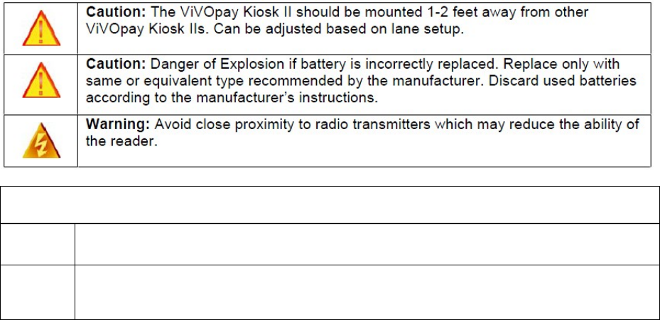
CautionsandWarnings
根據
NCC
低功率電波輻射性電機管理辦法
規定:
第十二條 經型式認證合格之低功率射頻電機,非經許可,公司、商號或使用者均不得擅自變更頻率、
加大功率或變更原設計之特性及功能。
第十四條 低功率射頻電機之使用不得影響飛航安全及干擾合法通信;經發現有干擾現象時,應立即
停用,並改善至無干擾時方得繼續使用。前項合法通信,指依電信法規定作業之無線電通信。
低功率射頻電機須忍受合法通信或工業、科學及醫療用電波輻射性電機設備之干擾。
Copyright©2010-2014,InternationalTechnologies&SystemsCorp.Allrightsreserved.
Page4of19
Table of Contents
Overview..............................................................................................................5
Features............................................................................................................5
ValidCard Types...............................................................................................5
Kiosk II Specifications.......................................................................................6
ViVOpayKioskIIInstallation.............................................................................7
PartList.............................................................................................................7
Mounting the ViVOpay KioskIIExternal Antenna.............................................8
Flush- Mounting the Square BezelAntenna................................................10
Mounting the ViVOpay KioskIIController.......................................................10
MountingtheViVOpayKioskII ControllerUsingScrews.............................10
MountingtheViVOpayKioskIIControllerUsingMountingTape.................11
AttachingtheCablesfromtheAntennatothe Controller................................11
Connectingto Power.......................................................................................12
Connecting to the Data Port............................................................................13
UsingtheViVOpayKioskIIto Make a Purchase.............................................14
PresentingCards,Fobs,orNFCPhones ....................................................14
Making a Purchase......................................................................................14
InstallationPoints.............................................................................................14
RFInterference..................................................................................................15
Troubleshooting................................................................................................16
Firmware Upgrade............................................................................................17
Serial Firmware Download Process................................................................17
Preparation..................................................................................................17
Load the ViVOpay KioskFirmware..................................................................17
USB FirmwareDownload................................................................................18
Symbols explanations.......................................................................................19
Copyright©2010-2014,InternationalTechnologies&SystemsCorp.Allrightsreserved.
Page5of19
Overview
The ViVOpayKiosk II is a compactstand-alone contactless readerdesigned to support
contactless transactions based on ISO 14443Type A/Type B/MiFare compatible cards,
fobs, and tags aswell as NFC phones.The ViVOpay Kiosk II is comprised of a compact
controller module and an antenna module packaged individually. This two-part design
allows the controller module to be installedwithin thecabinetry of a kiosk and the
antenna installed on an exterior surface witha separation of up to 1 meter. The antenna
is availablewith a square or angled bezel.
The ViVOpayKiosk II supportsUSB andserialRS232host communication usingthe
protocol defined in theGlobal Reader Serial InterfaceDevelopers Guide. The ViVOpay
Kiosk II is designed to support a wide input power range. Both dataand powercan be
supplied via asinglecable to reducing the effort and complexity of installation.
Features
Supports ISO14443 TypeA, Type B, MiFareand NFC basedcontactless
transactions
32-bit Microcontroller withample memory capable of supporting future
application upgrades
Crypto data processing forcontactless EMV cards
RS232(9600,19200, 38, 400, 57, 600,115, 200 baud) host interface
RS232 or USB data communications
Small antenna flush-mounted on external cabinetry with square or angled bezel
Internal mounted controller board with1meter controller/antenna separation
Valid CardTypes
ViVOpay Kiosk II supports the followingcontactless payment applications in thelatest
release of firmware:
ISO 14443
PayPass M/Stripe
PayPass M/Chip
PayPass MXI
VisaWave 1 and 2
VisaPay/Wave MSD and qVSDC
JCBJ/Speedy
JCB Mobile/QuicPay
American Express- ExpressPay
Discover Zip
MiFare ePurse

Copyright©2010-2014,InternationalTechnologies&SystemsCorp.Allrightsreserved.
Page6of18
KioskII Specifications
Hardware
MTBF 500,000 hrsbased on TelcordiaTechnologies
SR-332 modeled at 40°C.
Transmitter F
r
equency 13.56 MHz +
/
-0.01%
TransmitterModulation ISO 14443-2Type
A
Rise/Fall Time: 2-3 µsec.Rise, <1 µsec fall
ISO 14443-2Type B
Rise/Fall Time: <2 µsec. each; 8%-14%ASK
Receiver Subcarrier F
r
equency 847.5 KHz
Receiver Subcarrier Data ISO 14443-2Type A: Modified Mancheste
r
ISO 14443-2Type B: NRZ-l, BPSK
Typical ReadRange 4-6 cm (1.5 to 2.3 inches)
Ph
y
sical
Controlle
r
Height 105 mm (4.13 inches)
Width 76.2 mm (3.00 inches)
Depth 22.5 mm (0.88 inches)
Square BezelAntenna Height 75 mm (2.95 inches)
Width 60 mm (2.36 inches)
Depth 16.8 mm (0.66 inches)
A
ngle Bezel Antenna Height 96.2 mm (3.787 inches)
Width 82.3 mm (3.24 inches)
Depth 16.8 mm (0.66 inches)
En
v
ironmental
Operating Temperature -25° to 70° C(-13° to 158° F)
Storage Temperature -40° to 85° C(-40° to 185° F)
Operating Humidity 10% to 90% non-condensing
Electrical
Reader Input Voltage +7.5v to 36 VDC (by AC to DC adapter)
Copyright©2010-2014,InternationalTechnologies&SystemsCorp.Allrightsreserved.
Page7of18
ViVOpay Kiosk II Installation
Thissection provides information on how to install the ViVOpay Kiosk II on a kiosk.
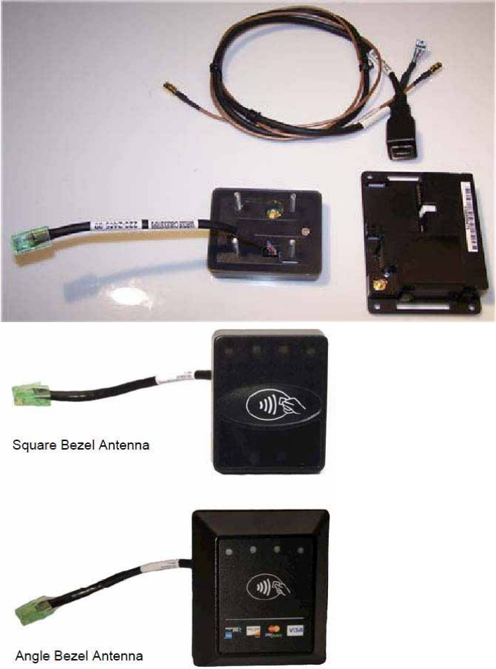
PartList
Verify that you have the following hardwarefor the installation of the ViVOpay Kiosk II:
ViVOpay Kiosk II Controller
ViVOpay Kiosk II Antenna(either square or angle bezel)
Antenna LED power and data cable
ViVOpay Kiosk II to ECR/POS cable(customer supplied). This USB or serial
cable varies based on thehost to be used.
Drill Template for the antenna (630-1046-00)
Copyright©2010-2014,InternationalTechnologies&SystemsCorp.Allrightsreserved.
Page8of19
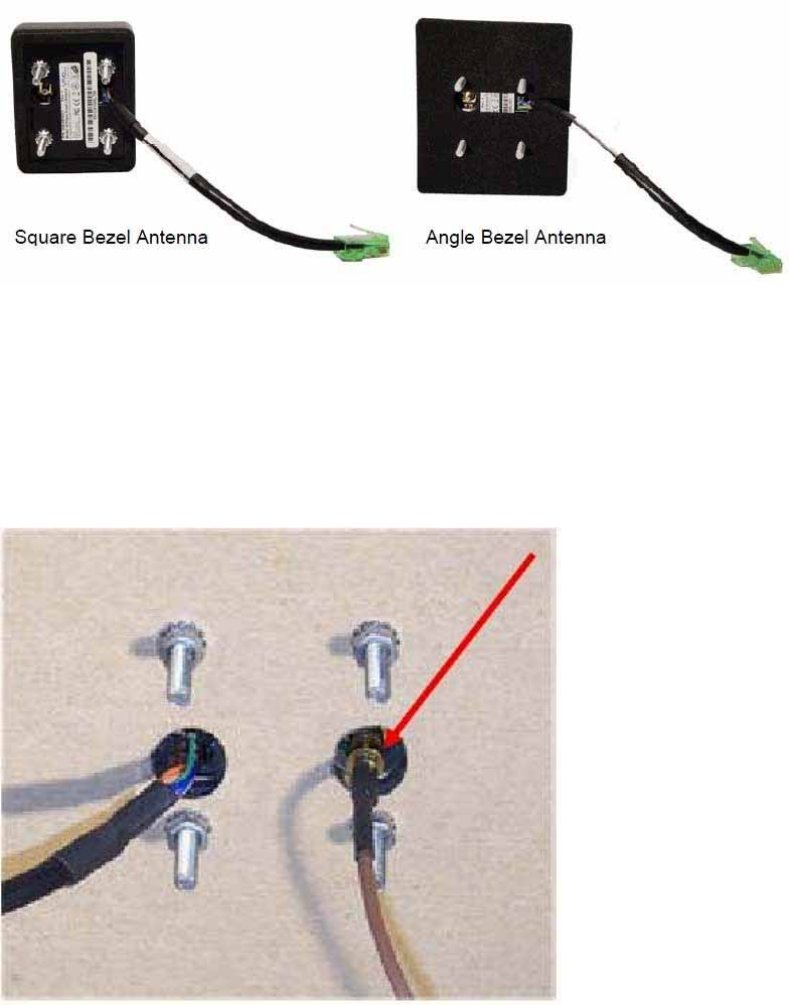
MountingtheViVOpayKioskII ExternalAntenna
Use the following instructions to mount the antenna on the exteriorof the kiosk:
Note: Verify the orientationof the ViVOpay Kiosk II Antenna beforemarking anddrilling
the holes. The two larger holesshould be located towards the top ofthe mounting
location to ensure that the ViVOpay KioskII Antennais oriented correctly with the LEDs
at the top.
1. Using the Drill Template for the antenna(630-1046-00), locate and mark the four
4.4mm (0.173 inch) mounting holes.
2. Using the Drill Template, locate and mark the two 14.0 mm (0.551 inches) across
holes (used for connectingthe antennapower and the LED power and datacable to
the ViVOpay Kiosk II).
3. Drill the four 4.4 mm (0.173) mounting holes using a number 17 drill bit.
4. Drill the two 14.0 mm (0.551 inch) holesusing a 35/64 drill bit.
5. Remove thenuts from thefour mountingscrews.
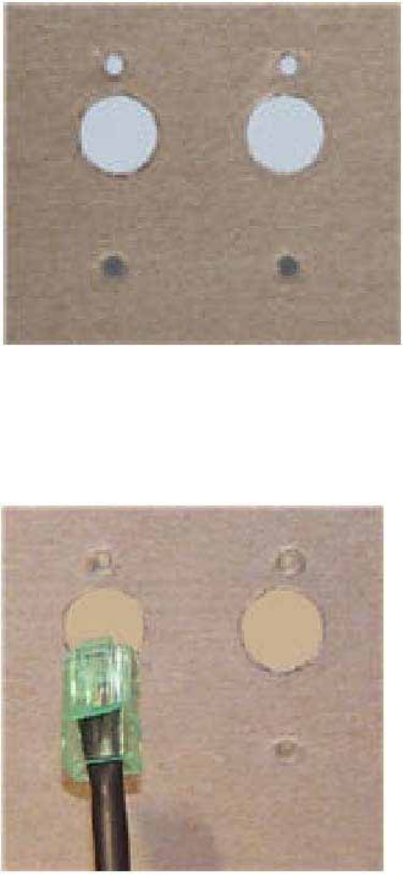
6. Route the end of the cable(220-2457-00) with the RJ45 connectorthrough the left
14.0 mm (0.551 inch) hole in to the kiosk. Make sure that the front of the antenna will
be properly oriented(not upside down)on the kiosk before inserting the fourscrews
into the mounting holes.
Copyright©2010-2014,InternationalTechnologies&SystemsCorp.Allrightsreserved.
Page9of19
7. Align the four screwswith the mounting holes and attach the ViVOpay Kiosk II to the
outside surface. Make sure that the cable is not pinched or binding.
8. Use the fournuts to secure the ViVOpayKiosk II to the outside surface of thekiosk.
Makesure to tighten the nuts securely sothat the ViVOpay Kiosk II does not move
on the outside surface of the kiosk.
If you are installing the Angle Bezel Antenna, tighten the nuts to 5-7in/lbs. for a good
weather seal.
9. Attach the end of the cablewith the SMB connector through the right 14.0 mm (0.551
inch) hold and attach it to the socketonthe back of the ViVOpay Kiosk II antenna. The
SMB connector pushes on the socket of the antenna.
Copyright©2010-2014,InternationalTechnologies&SystemsCorp.Allrightsreserved.
Page10of19
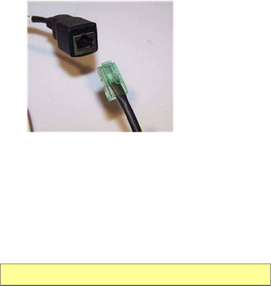
10.Attach the RJ45 connectorcoming fromthe ViVOpay Kiosk II Antenna to the RJ45
receptacle onthe 220-2457-00cable.
Flush- Mounting the Square Bezel Antenna
The RF fieldof the antenna is sensitiveto the proximity of metal.Ifyou are flush-
mounting theantenna in a metal surfaceor bezel, you have three options:
Mount with the RF emittingsurface of the antenna at least 1 cm forward of any
metal.
Mount with the RF emittingsurface of the antenna at least 1 cm behind any
metal. This will reduce theeffective range of the antenna.
Mount flushwith the metal but allow aminimum of 1cm spacing between the
antenna and the metal.
In all cases, test the antenna mounting before engaging in a full scale installation.
MountingtheViVOpayKioskII Controller
Note: The ViVOpay Kiosk II Controller must be mounted within 1meter of the antenna. If the
antenna is mounted on a surface that opens (such asa door), make sure the controller and
antenna areclose enough that there is no tension on the cable when the enclosure is open.
If it is acceptable, the installer can drill four holes for mounting thecontroller if screw
heads can appear on the outside of thekiosk.In thiscase, it wouldbe advisableto use
security screws to preventtampering with the screws.
If drilling additional holes on the outside ofthe kiosk surface is notacceptable, the
installer can use double-sided tape to mountthe controller to any clean surface.
Mounting the ViVOpayKiosk II Controller Using Screws
1. Position theViVOpay Kiosk II controller on the interior of the kiosk making sure that
there issufficient room for the antenna mountingsurface to be fully opened.
Copyright©2010-2014,InternationalTechnologies&SystemsCorp.Allrightsreserved.
Page11of19
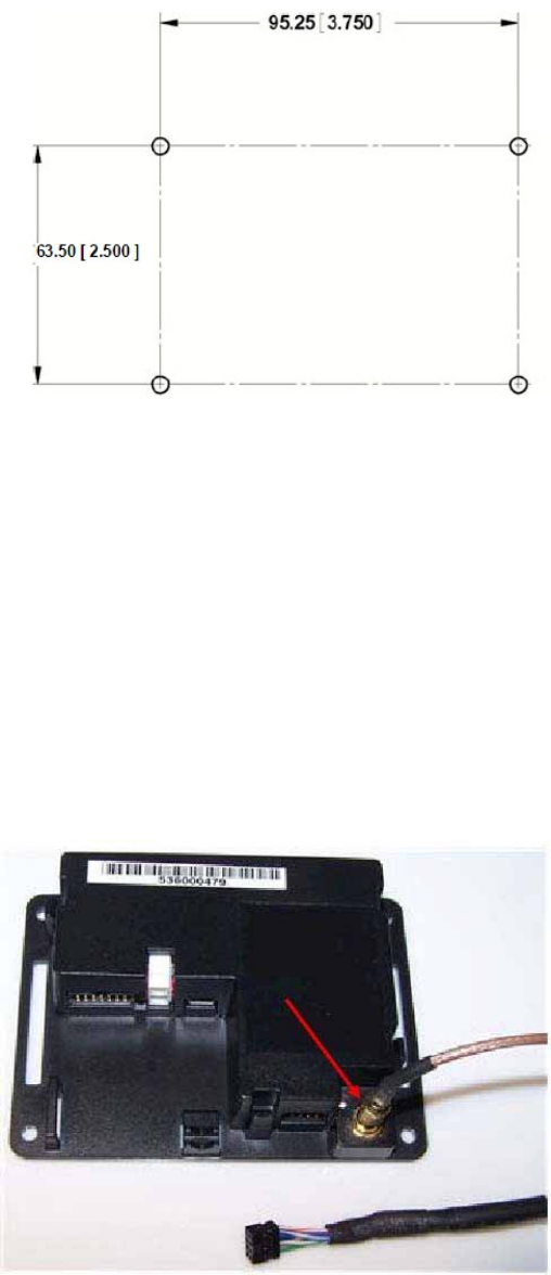
2. Locate the four 4.4 mm (0.173 inch) mounting holesby holding the ViVOpay Kiosk II
Controller in position andmark the holes. The following diagramshows the spacing
on the holes to be drilled for mounting the ViVOpay Kiosk II Controller.
3. Drill the four 4.4 mm (0.173 inch) mounting holes using a number 17 drill bit.
4. Use fourscrews and nuts to mount theViVOpay Kiosk II Controller to the kiosk
surface. (Mounting screws are not provided and must be supplied bythe installer.)
5. Tighten the nuts to hold the ViVOpay Kiosk II Controller in positionso that it does not
move.
Mounting the ViVOpayKiosk II Controller Using Mounting Tape
1. Position theViVOpay Kiosk II Controller on the interior of the kiosk making sure that
there issufficient room for the antenna mountingsurface to be fully opened.
2. Attach double-sided tape tothe mountingsurface.
3. Position theViVOpay Kiosk II Controller over the mounting tape and gently apply
pressure to hold the controller in position.
AttachingtheCablesfromtheAntennatotheController
1. Attach the SMB end of the cable (220-2457-00) from the antenna to the ViVOpay
Kiosk II Controller.
Copyright©2010-2014,InternationalTechnologies&SystemsCorp.Allrightsreserved.
Page12of19
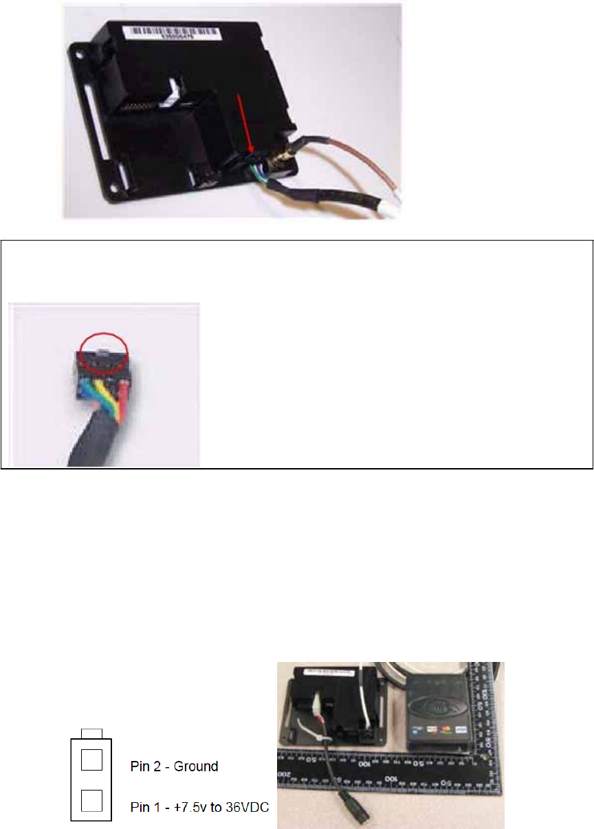
2. Attach the other end of the cable (220-2457-00) from the antenna to the ViVOpay
Kiosk II Controller.
Note: Verify that the polarizing plug on the end of thedata cable isfacing towards the top of the
ViVOpay Kiosk II Controller (away from the mounting plate) before inserting the cable.If the
cable is installed incorrectly (upside-down), it willapply the wrong polarity to the LEDs and
damage them.
Connecting to Power
The Kiosk II can be powered through the serial communications port or the two-socket
power connector. If you are using USB data communications, you must power the Kiosk
II through the two-socket power connector.
By using AC to DC adapter to Connect to the white two-socket Molex connector
(mating connector Molex P/N 0039012020with 5556-series crimps) or to pins 1 and
2 of the RS232 connector (see next section).
(P.S Please don’t use DC power source for our units, and this product do not supply
the DC Jack Cable).
Copyright©2010-2014,InternationalTechnologies&SystemsCorp.Allrightsreserved.
Page13of19
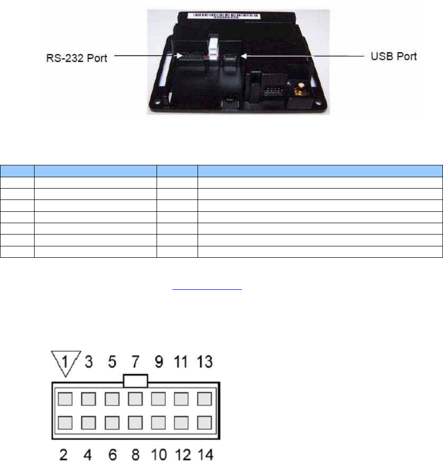
Connecting to the Data Port
The Kiosk II has two data connections options: USB through the USB connector and
RS232 through the 14-pin Molex connector.
The USB port uses a standard USB connector and pin outs. TheRS232 port has the
following pin outs.
Pin Description Pin Description
1 Power ground 2 +7.5v to 36VDC (By using AC to DC adapter)
3 Power ground 4 +7.5v to 36VDC (By using AC to DC adapter)
5 No connection 6 Reserved
7 Reserved 8 Reserved
9 Signal ground 10 Signal ground
11 RS232 Tx 12 RS232Rx
13 ISP Input 14 Reserved
To build your ownRS232cable, use Molex female connector part number 0511101451
with 50394-series crimps (see www.molex.comfor more information). Pin 1 is indicated
by a triangle (diagram issocket-side viewof the female connector). Ifyou are powering
the Kiosk II from this connector,wire the two powerpins (pins 2 and 4) together and the
two power ground pins together (pins 1 and 3).

Copyright©2010-2014,InternationalTechnologies&SystemsCorp.Allrightsreserved.
Page14of19
UsingtheViVOpayKioskIItoMakeaPurchase
Presenting Cards, Fobs, or NFC Phones
Your new ViVOpay Kiosk II allows for credit/debit card purchasesusing the new
contactless technology.
Present the card/fob/phone in close proximity tothe front portion ofthe antennamodule.
Present the card/fob/phone so that maximum surfacearea is parallel to the antenna
module as shown below. The antenna should beep and all four green LEDs should
illuminate briefly to indicate a successful test.
This tests theantenna’s ability to read the RFIDtest card. If unsuccessful, therewill be no
reaction from the reader. If you use a test card andthe ViVOpay reader is attached to the
ViVOpay Kiosk II Controller, a dummytransactioncan be tested. The transaction will not
be authorized and willcome backwith a response,but will at least test for end-to-end
connectivity.
Making aPurchase
After the transaction has been enteredonthe kiosk control panel, the customer should
present their card/fob/phone in close proximity so that maximum surfacearea is
parallel to the antenna.
A single beep and all fourLEDs briefly flashing indicates the card/fob/phone has
been readcorrectly.
Installation Points
The ViVOpayKiosk II is designed to bemounted on ametal surface and in close
proximity to any internal motors and electrical devices that may beoperating inside
the kiosk. However, the ViVOpay Kiosk IIis susceptible to RF andelectromagnetic
interference. It is importantthat the unit not be mounted near(within3 or 4 feet) large
electric motors, computerUPS systems,microwave transmitters, anti-theft devices,
radio transmitters, communications equipment and so on.
Close proximity of metal tothe RF-emitting end of theantenna can greatly reduce the
range of the antenna. See the precautions describedin FlushMounting the Kiosk
IIAntenna.
Tie all cablesneatly with nylon cable-tiesand route them so that they are
inaccessibleand invisible to customers.Label thecable ends, host,ViVOpay, and
power, to simplify connection testing or component replacement.
Copyrig
h
t©2010-2014,InternationalTechnologies&SystemsCorp.Allrig
h
tsreserved.
Page15of19
Test the ViVOpay Kiosk II installation using a test card to performan end-to-end
transaction (the same as an actual purchase on theKiosk). Thekiosk control panel
should display “Requesting Authorization”. Even if the transaction is declined (as it
should bewith a test card),it will proveconnectivity all the way through the system. If
possible the store manager or some other responsibleparty should test each cardto
ensurecontinued operationand functionality. If the kiosk is rebooted on a regular
basis (such as every night) it is importantto test the contactless reader as soonas
possible afterwards to ensure continuedcommunication to the kiosk.
Refer to the troubleshooting section of thismanual before contacting your distributor
with support questions.
RF Interference
Q. WhydoIneed to knowaboutRF interference?
A. Contactless payments use radio frequency technology to sendcard data to a
contactless terminal reader.
Q. HowcanRF interference affect contactless payments?
A. RF interference can cause data errors. If RF interference is present, contactless
payment devices may operation intermittently or inconsistently.
Q. Where does RF interference come from?
A. Radio frequency interference (RFI) can originate from a wide number of sources at the
point-of-sale (POS). Some examples of sources of RF energy andRF interference
include: AM/FM radioand TV transmitters
2-way radios,pagers
Mobile telephones
Power lines, transformers
Medical equipment
Microwaves
Electromechanicalswitches
Q. What should I do if I suspect RF interference exists in myenvironment?
A. Begin by inspecting your environmentfor possible sources ofRF interference.
Q. Do equipment manufacturers testtheir devices for RF interference?
A. Electronicequipment istested forRFI sensitivity by the manufacturers. Thesetests
are performed in a controlled laboratory environmentand will oftennot replicate the types
of devices that would be encountered inyour point-of- sale(POS)environment.
Q. WhatRF levelswill impactRF operations?
A. Factors that can causeRF interference vary case-by-case. There are noset rules
defining asingle RF level that will cause RFI. RFI depends on the sensitivity of the
equipment under consideration, or how low an interpreting signal can be in the presence
of the equipment and cause problems.
Equipment can be particularly sensitive to very low signal levels of one frequency and yet
be quite immune to highsignal levels of another frequency-so frequency is an important
factor.
Some electronic system components areinternally shielded and have a very high
immunity to interference; but generally, most equipment has not been so engineered.

Copyrig
h
t©2010-2014,InternationalTechnologies&SystemsCorp.Allrig
h
tsreserved.
Page16of19
S
y
mptom Possible Cause Remed
y
Gene
r
al Issues
Reader does not
appear to bepowered
on (no LEDs lit).
Reader not powered on or
incorrect voltage.
Improper useof internal
power supplyprovided by
the kiosk.
Check cableconnections.
Verify that power is on and
correct voltage and currentare
present.
Makesure that the correct pins
are utilized.
Makesure that the power
provided is within the specified
range of the Kiosk II reader.
Makesure that the correct
polarity is observed.
For more information, refer to the
Input Voltageunder the Electrical
specificationsection.
Replace the ViVOpay Kiosk II.
Readin
g
Ca
r
ds/Fobs/Phones
LEDs do not light and
beeper is not audible
when card/fob/phone
is presented.
Card/fob/phone not
properly presented.
RF interference.
Unsupported card used.
Wrong firmware (contact
your local support
representative).
Present card/fob/phone closer to
the antenna, and ensure it is
parallel to the face of the reader.
Verify that the card/fob/phone is
valid/current.
Verify that metal is not interfering
with the antenna.
Testwith “Contactless Test
Card” part number 241-0015-03
RevA.
Verify that the Phone Wallet is
enabled for payments.
Try a differentcard/fob/phone.
Check to seeif card/fob/phone is
damaged.
Verify that phone cover is
correctly attached to phone
(Nokia 3220).
Verifythat correct firmwareis
loaded on reader (local support
representative only).
Power cableplug is fully
inserted.
Replace the ViVOpay Kiosk II.
Some
card/fobs/phones read,
but not all.
Possible bad
card/fob/phone.
Unsupported card used.
Wrong firmware (contact
your local support
representative).
Check to seeif card/fob/phone is
damaged.
Verify that phone cover is
correctly attached to phone.
Verifythat correct firmwareis
loaded on reader (local support
representative only).
Troubleshooting
The ViVOpayKiosk II readers arereliable and easy to troubleshoot. The components that
may require troubleshooting include thepowermodule (if applicable), the reader, and the
serial cable.

Copyrig
h
t©2010-2014,InternationalTechnologies&SystemsCorp.Allrig
h
tsreserved.
Page17of19
S
y
mptom Possible Cause Remed
y
Communication to Kiosk
No data is received, o
r
data is garbled.
Faulty or incorrect cable
connections.
Check that the cable connection
is secure and in the correct port
on the kiosk.
If you are unable to resolvethe problem, contact your localsupport representative.
Firmware Upgrade
The Kiosk II can be upgraded using either the serial or USB interfaces.
SerialFirmwareDownloadProcess
The ViVOpayKiosk II canonly be upgraded when it is placed in upgrade mode by
drawing down the ISP signal on the externalconnector. Using thecable and dongle
mentioned above accomplishes this by connecting theISP pin tothe RS232signal ground.
If the ISP is grounded when theViVOpay Kiosk II powerson, it enters download mode.
Otherwise it will operate normally, emitting abeep and flashing LEDs when powered on.
If you want to build your own downloadcable,the pinouts to the external connector are
given in Connecting to theData Port. After you have entered download mode, you must
erase the current firmware and install the new firmware.
Preparation
To install thenew firmwareyou will need:
PC with available serial orUSB port
ViVOpay Kiosk II with a serial orUSB data cable attached
For serial downloads: 220-1275-00 Download Dongle (DB-9 serialto RJ45)
Philips LPC2000 Flash Utility software
Firmware file for the desired firmware (contact
ViVOpaysupport@idtechproducts.com)
Power supplyfor the ViVOpay reader (7.5- 36 VDC; 3 Watts output).
LoadtheViVOpayKioskFirmware
1. Install the LPC2000 flash utility program on the PC.
2. Copy the ViVOpay Kiosk II firmware on the PC.
3. Connect the download dongle (220-1275-00) to thePC COM portand plug in the
220-2374-00cable from ViVOpay Kiosk II tothe dongle.
4. Connect the power to the ViVOpay reader. Thereshould be no beep, and no LED
activity.
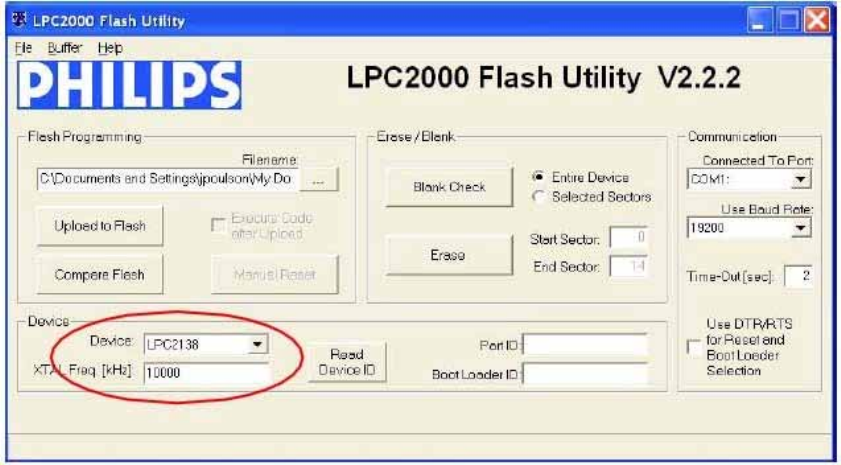
5. Launch the Philips LPC2000 utility. If the Philips utility fails to identify any reader
attached, please follow thetroubleshooting steps given in Troubleshooting.
6. Set the Device to LPC 2138.
Copyright©2010-2014,InternationalTechnologies&SystemsCorp.Allrightsreserved.
Page18of19
7. The COM port is normally set to1 but this depends upon your PCDevice Manager
setup. Youcan select the COM port to which thecable is connected by navigating to
the WindowsDevice Manager (Start ->Settings ->Control Panel->System -
>Hardware->Device Manager ->Ports) to verify theactual port number that is
assigned to the serial port. PressENTERafter making the selection.
8. ClickRead Device ID, thePart ID: andBoot LoaderID: fields should be filled inif the
reader is responding to the utility.
Note: If the reader does NOT respond to the utility, reset the reader by unplugging
and replugging the power connector andtry again.
9. ClickErase. This erases the old firmware on the reader. A message indicates a
successful erase.
10.ClickBlank Check (with Entire Device selected) to confirm that the erase function
worked properly.
11.In the Flash Programming box, click the “…” box to select the firmware file you want
to load on the ViVOpay Kiosk II.
12.ClickUploadto Flash to load the firmware on the reader (the % completion bar
shows the firmware loading progress).
13.Disconnect power and theserial dongle.
14.Connect power to the Kiosk II and connect the standard datacable. It will load the
new firmwareapplication.
USBFirmwareDownload
The download process over the USB interface is performed with the bootloader
commands presented in theSerial InterfaceDeveloper’s Guide. For a copy of the Serial
Interface Developers Guide contact ID TECH or yourID TECH representative.

Copyright©2010-2014,InternationalTechnologies&SystemsCorp.Allrightsreserved.
Page19of19
Symbols explanations
The symbol on the product or in the instructions means that your
electrical and electronic equipment should be disposed at the end its life
separately from your household waste.
There are separated collection systems for recycling in the EU.
For more information, please contact the local authority or your retailer
where you purchased the product.