Users Manual

ID TECH. 10721 Walker St., Cypress, CA
90630
Email: support@idtechproducts.com URL:
http://www.idtechproducts.com
Confidential
NEO Interface Developers Guide
80139403-001 Rev.116
8 Sep 2017
NEO Interface Developers Guide
ii
Copyright
Copyright © 2017, ID TECH. All rights reserved.
ID TECH
10721 Walker St.
Cypress, CA 90630
This document, as well as the software and hardware described in it, is furnished under license
and may be used or copied online in accordance with the terms of such license. The content of
this document is furnished for information use only, is subject to change without notice, and
should not be construed as a commitment by ID TECH. Reasonable effort has been made to
ensure the accuracy of information provided herein. However, ID TECH assumes no responsibility
or liability for any unintentional errors or inaccuracies that may appear in this document.
Except as permitted by such license, no part of this publication may be reproduced or
transmitted by electronic, mechanical, recording, or otherwise, or translated into any language
form without the express written consent of ID TECH. ID TECH and ViVOpay are trademarks or
registered trademarks of ID TECH.
Warranty Disclaimer: The services and hardware are provided "as is" and "as-available" and the
use of the services and hardware is at its own risk. ID TECH does not make, and hereby disclaims,
any and all other express or implied warranties, including, but not limited to, warranties of
merchantability, fitness for a particular purpose, title, and any warranties arising from a course
of dealing, usage, or trade practice. ID TECH does not warrant that the services or hardware will
be uninterrupted, error-free, or completely secure.
NEO Interface Developers Guide
iii
Table of Contents
1.0
INTRODUCTION .......................................................................................................................... 1
HISTORICAL BACKGROUND .................................................................................................................. 1
MasterCard Contactless (PayPass) Capability ........................................................................................ 1
Protocol 1 Deprecated ............................................................................................................................ 1
O
RGANIZATION OF THIS
G
UIDE
............................................................................................................................ 1
N
OTATIONAL
C
ONVENTIONS
............................................................................................................................... 2
R
EADER
I
NTERFACE
C
APABILITIES
......................................................................................................................... 2
2.0
QUICK REFERENCE ...................................................................................................................... 4
C
OMMAND
T
ABLES
........................................................................................................................................... 4
Commands Sorted by Command Name .................................................................................................. 4
Commands Sorted by Command Number ............................................................................................... 7
Pass-Through Command Table ............................................................................................................. 11
EMV Key Manager Command Tables.................................................................................................... 12
S
TATUS
C
ODES
............................................................................................................................................... 13
Status Codes for Protocol 1 ................................................................................................................... 13
Status Codes for Protocol 2 ................................................................................................................... 13
E
RROR
C
ODES
................................................................................................................................................ 15
RF
S
TATE
C
ODES
............................................................................................................................................ 18
3.0
SERIAL COMMUNICATION INTERFACES ....................................................................................... 20
RS232
S
ERIAL
I
NTERFACE
................................................................................................................................ 20
Port Settings .......................................................................................................................................... 20
Basic Communication ............................................................................................................................ 20
Timeouts ............................................................................................................................................... 20
USB
HID
I
NTERFACE
....................................................................................................................................... 21
HID Report Format ................................................................................................................................ 21
Sample Single Report Command and Response .................................................................................... 22
Data Frames .......................................................................................................................................... 23
Sample Single Report Command with Multiple Report Response ......................................................... 23
Error Handling at Report Level .............................................................................................................. 24
Error Handling at Command Level ........................................................................................................ 25
4.0
VIVOPAY COMMUNICATION PROTOCOLS ................................................................................... 26
P
ROTOCOL
1
(D
EPRECATED
) ............................................................................................................................. 26
Command Frames ................................................................................................................................. 26
ACK Frames ........................................................................................................................................... 26
NACK Frames ........................................................................................................................................ 27
Special Frames ...................................................................................................................................... 27
P
ROTOCOL
2.................................................................................................................................................. 27
Command Frames ................................................................................................................................. 27
Response Frames .................................................................................................................................. 28
P
ASS
-T
HROUGH
M
ODE
(P
ROTOCOL
2) ............................................................................................................... 28
NEO Interface Developers Guide
iv
Basic Pass-Through Operation .............................................................................................................. 28
Pass-Through Command Frame ............................................................................................................ 29
Pass-Through Response Frame ............................................................................................................. 29
Suggested Sequence for Pass-Through Commands .............................................................................. 29
Auto-Switch to Pass-Through Mode ..................................................................................................... 30
RF On/Off States for Pass-through Commands ..................................................................................... 33
B
URST
M
ODE
................................................................................................................................................ 33
ViVOpay Burst Mode Frames ................................................................................................................ 34
CRC
C
ALCULATION
......................................................................................................................................... 42
5.0
TAG AND DATA SET CONFIGURATION ......................................................................................... 45
C
ONFIGURABLE
AID
S AND
G
ROUPS
.................................................................................................................... 46
System AIDs .......................................................................................................................................... 48
User AIDs ............................................................................................................................................... 48
Reader Default TLV Group .................................................................................................................... 49
PayPass Default Group ......................................................................................................................... 49
User-defined TLV Groups ...................................................................................................................... 49
Configurable AID Reader Memory Requirement................................................................................... 50
ViVOpay Proprietary TLVs ..................................................................................................................... 51
C
ARD
A
PPLICATION
P
ROPRIETARY
T
AG
L
IST
(FF69) .............................................................................................. 51
C
ONFIGURATION
T
AG
T
ABLES
........................................................................................................................... 52
Global Configuration Tags .................................................................................................................... 52
Group Configuration Tags ..................................................................................................................... 56
PayPass Group Configuration TLVs ....................................................................................................... 64
PayPass Group Configuration TLVs with Hard-Coded Values in Kernel ................................................ 70
American Express Group Configuration TLVs ........................................................................................ 75
AID Configuration Tags ......................................................................................................................... 78
6.0
CARD APPLICATION SELECTION .................................................................................................. 85
C
OMBINED
S
ELECTION
..................................................................................................................................... 85
Selection Features (FFE3) ...................................................................................................................... 85
P
ARTIAL
S
ELECTION
(FFE1) .............................................................................................................................. 86
AID
P
ARTICIPATION IN
S
ELECTION
P
ROCESSES
(FFE8) ........................................................................................... 86
T
ERMINAL
AID
L
IST
(DFEF2C) ......................................................................................................................... 87
7.0
CARD APPLICATION SPECIFIC BEHAVIOR ..................................................................................... 88
M
ASTER
C
ARD
P
AY
P
ASS
M/C
HIP
....................................................................................................................... 88
PayPass Default Group ......................................................................................................................... 88
Balance Read Function .......................................................................................................................... 88
Torn Transaction Recovery.................................................................................................................... 89
EMV Certificate Revocation List ............................................................................................................ 89
Stop Transaction Command .................................................................................................................. 89
Proprietary Tag List ............................................................................................................................... 89
PayPass Personalization Limits ............................................................................................................. 89
8.0
PROTOCOL COMMAND REFERENCE: PROTOCOL 1 ....................................................................... 91
T
RANSACTION
R
ELATED
C
OMMANDS
.................................................................................................................. 91
Flush Track Data (17-02) ....................................................................................................................... 91
Get Full Track Data (17-CD) .................................................................................................................. 91
Get ViVOpay Firmware Version (29-00) ................................................................................................ 94
K
EY
M
ANAGER
C
OMMANDS
P
ROTOCOL
1 ........................................................................................................... 95
Set CA Public Key (24-01) Protocol 1 ..................................................................................................... 96
Delete CA Public Key (24-02) Protocol 1 .............................................................................................. 100
NEO Interface Developers Guide
v
Delete All CA Public Keys (24-03) Protocol 1 ....................................................................................... 102
M
ISCELLANEOUS
P
ROTOCOL
1
C
OMMANDS
....................................................................................................... 103
Set RF Error Reporting (17-03) ............................................................................................................ 103
RTC
(R
EAL
T
IME
C
LOCK
)
S
ET
U
P
C
OMMANDS
................................................................................................... 103
RTC Set Time (25-01) ........................................................................................................................... 104
RTC Get Time (25-02) .......................................................................................................................... 105
RTC Set Date (25-03) ........................................................................................................................... 105
RTC Get Date (25-04) .......................................................................................................................... 107
9.0
PROTOCOL COMMAND REFERENCE: PROTOCOL 2 ..................................................................... 109
G
ENERAL
C
OMMANDS
................................................................................................................................... 109
Ping (18-01)......................................................................................................................................... 109
Set Poll Mode (01-01) ......................................................................................................................... 109
Control User Interface (01-02) ............................................................................................................ 110
Set/Get Source for RTC/LCD/Buzzer/LED (01-05) ................................................................................ 112
Set Configuration Defaults Command (04-09) .................................................................................... 114
Set Configuration Defaults and Keep Encrypt Key Command (04-0A) ................................................ 116
Set Configuration (04-00) .................................................................................................................... 116
Get Configuration (03-02) ................................................................................................................... 117
Get Version Protocol 2 (29-00) ............................................................................................................ 118
Get USB Boot Loader Version (29-04) ................................................................................................. 119
Get Contact EMV L2 Kernel Version (29-06) ....................................................................................... 119
Get Contact EMV L2 Kernel Version Detail (29-07) ............................................................................. 120
Get Contact EMV L2 Kernel Checksum (29-08) ................................................................................... 120
Get Contact EMV L2 Terminal Configuration Checksum (29-09) ........................................................ 121
Get UID of MCU (29-17) ...................................................................................................................... 122
Set Baud Rate (30-01) ......................................................................................................................... 122
Set Temporary Baud Rate (30-02) ....................................................................................................... 123
Set Baud Rate and Audio Level (30-03) – UniPay 1.5 & UniPay III ...................................................... 124
Set Cable Type (32-02) ........................................................................................................................ 125
Get Cable Type (32-01) ....................................................................................................................... 125
Set Serial Number (12-02) ................................................................................................................... 126
Get Serial Number (12-01) .................................................................................................................. 126
Bootup Notification Command (14-01) ............................................................................................... 127
C
ONFIGURABLE
AID
AND
G
ROUP
C
OMMANDS
................................................................................................... 128
Set Configurable AID (04-02) .............................................................................................................. 128
Set Configurable Group (04-03) .......................................................................................................... 130
Get Configurable AID (03-04) .............................................................................................................. 131
Get Configurable Group (03-06) ......................................................................................................... 131
Delete Configurable AID (04-04) ......................................................................................................... 132
Delete Configurable Group (04-05) ..................................................................................................... 133
Get All AIDs (03-05) ............................................................................................................................. 134
Get All Groups (03-07) ........................................................................................................................ 135
T
RANSACTION
R
ELATED
C
OMMANDS
:
C
ONTACT
................................................................................................. 135
Setting transaction parameters .......................................................................................................... 136
Contact EMV L2 Transaction Flow ...................................................................................................... 137
Contact Retrieve Application Data (60-01) ......................................................................................... 138
Contact Remove Application Data (60-02) ......................................................................................... 138
Contact Set Application Data (60-03) ................................................................................................. 139
Contact Retrieve Terminal Data (60-04) ............................................................................................. 140
Contact Remove Terminal Data (60-05) ............................................................................................. 141
Contact Set Terminal Data (60-06) ..................................................................................................... 142
Contact Retrieve AID List (60-07) ........................................................................................................ 148
NEO Interface Developers Guide
vi
Contact Retrieve CA Public Key (60-08) ............................................................................................... 149
Contact Remove CA Public Key (60-09) ............................................................................................... 150
Contact Set CA Public Key (60-0A) ...................................................................................................... 151
Contact Retrieve CA Public Key List (60-0B) ........................................................................................ 152
Contact Retrieve Certification Revocation List (60-0C) ....................................................................... 152
Contact Remove Certification Revocation List (60-0D) ....................................................................... 153
Contact Set Certification Revocation List (60-0E)................................................................................ 154
Contact Remove Transaction Amount Log (60-0F) ............................................................................. 155
Contact Start Transaction (60-10) ...................................................................................................... 155
Contact Authenticate Transaction (60-11).......................................................................................... 161
Contact Apply Host Response (60-12) ................................................................................................. 164
Contact Retrieve Transaction Result (60-13) ...................................................................................... 167
Contact Get Reader Status (60-14) ..................................................................................................... 169
Contact Get ICS Identification (60-15) ................................................................................................ 169
Contact Set ICS Identification (60-16) ................................................................................................. 170
Contact LCD Display Control (61-01) (Reader send to Host) ............................................................... 171
Contact Get PIN Control (61-02) (Reader send to Host) ...................................................................... 173
Contact Get MSR Data Control (Reader send to Host)(61-03) ............................................................ 176
T
RANSACTION
R
ELATED
C
OMMANDS
:
C
ONTACTLESS
........................................................................................... 178
Activate Transaction Command, Contactless (02-01 and 02-40) ........................................................ 178
Get Transaction Result (03-00 and 03-40) .......................................................................................... 202
Update Balance Command (03-03) ..................................................................................................... 207
Cancel Transaction Command (05-01) ................................................................................................ 208
M
ASTER
C
ARD
M/C
HIP
3.0
T
RANSACTION
C
OMMANDS
...................................................................................... 209
Stop Transaction (05-02) ..................................................................................................................... 209
Reset Torn Transaction Log (84-0E) .................................................................................................... 210
Clean Torn Transaction Log (84-0F) Command ................................................................................... 211
V
ISA
VCPS
T
RANSACTION
C
OMMANDS
............................................................................................................ 212
Set Cash Transaction Reader Risk Parameters (04-0C) ....................................................................... 212
Get Cash Transaction Reader Risk Parameters (03-0C) ...................................................................... 213
Set Cashback Transaction Reader Risk Parameters (04-0D) ............................................................... 214
Get Cashback Transaction Reader Risk Parameters (03-0D) .............................................................. 215
Set DRL Reader Risk Parameters (04-0E) ............................................................................................ 216
Get DRL Reader Risk Parameters (03-0E) ............................................................................................ 217
K
EY
M
ANAGEMENT
C
OMMANDS
..................................................................................................................... 218
Get CA Public Key (D0-01) ................................................................................................................... 219
Get CA Public Key Hash (D0-02) .......................................................................................................... 220
Set CA Public Key (D0-03) .................................................................................................................... 221
Delete CA Public Key (D0-04) .............................................................................................................. 221
Delete All CA Public Keys (D0-05) ........................................................................................................ 222
Get All CA Public RIDs (D0-06) ............................................................................................................. 222
List CA Public Key IDs or RID (D0-07) ................................................................................................... 223
M
ODULE
V
ERSIONING
................................................................................................................................... 223
Get Product Type (09-01) .................................................................................................................... 225
Get Processor Type (09-02) ................................................................................................................. 226
Get Main Firmware Version (09-03) ................................................................................................... 227
Get Hardware Information (09-14) ..................................................................................................... 228
Get Module Version Information (09-20) ............................................................................................ 229
I
NTERNATIONAL
L
ANGUAGE
S
UPPORT
............................................................................................................... 230
Other Language .................................................................................................................................. 231
Bitmap Conversion Completed by POS ................................................................................................ 231
ILM Header Format ............................................................................................................................. 231
Language Version Information ........................................................................................................... 232
NEO Interface Developers Guide
vii
EMV
C
ERTIFICATE
R
EVOCATION
L
IST
C
OMMANDS
.............................................................................................. 233
Get EMV Revocation Log Status (84-03) ............................................................................................. 234
Add Entry to EMV Revocation List (84-04) .......................................................................................... 234
Delete All Entries for Single Index in EMV Revocation List (84-05) ..................................................... 235
Delete All Entries from EMV Revocation List (84-06) .......................................................................... 235
Get EMV Revocation List (84-07) ........................................................................................................ 236
Delete an Entry from EMV Revocation List (84-0D) ............................................................................ 237
EMV
E
XCEPTION
L
OG
L
IST
C
OMMANDS
........................................................................................................... 238
Get EMV Exception Log Status (84-08) ............................................................................................... 238
Add Entry to EMV Exception List (84-09) ............................................................................................ 238
Delete Entry from EMV Exception List (84-0A) .................................................................................... 239
Delete All Entries from EMV Exception List (84-0B) ............................................................................ 240
Get EMV Exception List (84-0C)........................................................................................................... 240
G
ENERIC
P
ASS
-
THROUGH
C
OMMANDS
............................................................................................................. 241
Pass-Through Mode Start/Stop (2C-01) .............................................................................................. 241
Get PCD and PICC Parameters (2C-05) ................................................................................................ 242
Poll for Token (2C-02) ......................................................................................................................... 243
Enhanced Poll for Token (2C-0C) ......................................................................................................... 245
Get ATR (2C-12)................................................................................................................................... 248
Antenna Control (28-01) ..................................................................................................................... 250
P
ASS
-
THROUGH
UI
C
ONTROL
.......................................................................................................................... 250
LED Control (0A-02) ............................................................................................................................. 250
Buzzer Control (0B-xx) ......................................................................................................................... 251
P
ASS
-
THROUGH
D
ATA
E
XCHANGE
.................................................................................................................... 252
Exchange Contactless Data (2C-03) .................................................................................................... 252
PCD Single Command Exchange (2C-04) Protocol 2 ............................................................................ 253
High Level Halt Command (2C-09) ...................................................................................................... 257
Enhanced Pass-Through Command (2C-0B) ....................................................................................... 257
Single Shot Commands........................................................................................................................ 261
Exchange APDU Data (2C-13) ............................................................................................................. 265
Contact Card Power Off (2C-18) .......................................................................................................... 266
H
IGH
L
EVEL
P
ASS
-T
HROUGH
C
OMMANDS FOR
M
IFARE
C
ARDS
.............................................................................. 267
Mifare Authenticate Block (2C-06) ...................................................................................................... 267
Mifare Read Blocks (2C-07) ................................................................................................................. 268
Mifare Write Blocks (2C-08) ................................................................................................................ 270
Mifare ePurse Command (2C-0A) ....................................................................................................... 271
H
IGH
L
EVEL
P
ASS
-T
HROUGH
C
OMMANDS FOR
NFC
C
ARDS
.................................................................................. 277
NFC Commands (2C-40) ...................................................................................................................... 277
S
ECURE
P
ASS
-T
HROUGH
F
UNCTION
................................................................................................................. 280
10.0
SECURE COMMUNICATION .................................................................................................. 288
Burst mode .......................................................................................................................................... 288
Data Output ........................................................................................................................................ 288
Encryption Algorithms......................................................................................................................... 288
Secure Data Exchange ........................................................................................................................ 289
Padding of Data Fields ........................................................................................................................ 289
Set Data Encryption Key Variant Type (C7-2F) .................................................................................... 290
Get Data Encryption Key Variant Type (C7-30) ................................................................................... 290
Set DUKPT Key Encryption Type (C7-32) ............................................................................................. 291
Get DUKPT Key Encryption Type (C7-33) ............................................................................................. 291
Set Data Encryption Enable Flag (C7-36) ............................................................................................ 292
Get Data Encryption Enable Flag (C7-37)............................................................................................ 294
Set MSR Secure Parameters (C7-38) ................................................................................................... 294
NEO Interface Developers Guide
viii
Get MSR Secure Parameters (C7-39) .................................................................................................. 295
K
EY
I
NJECTION AND
R
ELATED
C
OMMANDS
........................................................................................................ 296
Set Remote Key Injection Timeout (C7-2D) ......................................................................................... 296
Get Remote Key Injection Timeout (C7-2E) ......................................................................................... 296
Check DUKPT Keys (81-02) .................................................................................................................. 297
Check DUKPT Key (81-04) .................................................................................................................... 298
Get DUKPT Key Serial Number (KSN) (81-0A)...................................................................................... 299
11.0
IMPROVED COLLISION DETECTION ....................................................................................... 301
Issues with Standard Collision Detection ............................................................................................ 301
Collision Detection Modes................................................................................................................... 302
12.0
KIOSK III BOOT LOADER ....................................................................................................... 305
D
ESCRIPTION
............................................................................................................................................... 305
B
OOT
P
ROCEDURE
........................................................................................................................................ 305
C
OMMUNICATION
P
ROTOCOL
......................................................................................................................... 306
F
IRMWARE
D
OWNLOADER
F
ILE
N
AME
F
ORMAT
................................................................................................. 306
F
IRMWARE
D
OWNLOADER
D
ATA
F
ORMAT
........................................................................................................ 307
D
OWNLOAD
F
IRMWARE
S
TEPS
........................................................................................................................ 308
F
IRMWARE
D
OWNLOADER
C
OMMANDS
............................................................................................................ 308
Enter Boot Loader Process from Main Application (C7-41) ................................................................. 308
Get Boot Loader Version (C7-10) ........................................................................................................ 308
Start Update Process (C7-11) .............................................................................................................. 309
Erase Boot/Application Space(C7-12) ................................................................................................. 309
Send Encrypted Firmware Check Value(C7-13) ................................................................................... 310
Send Firmware Data (C7-14) ............................................................................................................... 311
End Update Process (C7-15) ................................................................................................................ 311
Start Application (C7-16) ..................................................................................................................... 312
Firmware Downloader Command Processing Flow ............................................................................ 312
13.0
UNIPAY 1.5 & UNIPAY III COMMANDS .................................................................................. 314
Set PMC Status (F0-00) ....................................................................................................................... 314
Get PMC Status (F0-01) ....................................................................................................................... 315
Get Battery Level (F0-02) .................................................................................................................... 315
Shut Off the Power (F0-0F) .................................................................................................................. 316
14.0
VIVOPAY VENDI READER COMMANDS .................................................................................. 318
Configure Buttons (F0-F4) ................................................................................................................... 318
Get Button Configuration (F0-F5) ....................................................................................................... 318
Disable Blue LED Sequence (F0-F6) ..................................................................................................... 319
Enable Blue LED Sequence (F0-F7) ...................................................................................................... 320
LCD Display Clear (F0-F9) .................................................................................................................... 321
Turn Off Yellow LED (F0-FA) ................................................................................................................ 321
Turn On Yellow LED (F0-FB)................................................................................................................. 322
Buzzer On/Off (F0-FE) ......................................................................................................................... 322
LCD Display Line 1 Message (F0-FC) .................................................................................................... 323
LCD Display Line 2 Message (F0-FD) ................................................................................................... 323
15.0
APPLEPAY VAS AND OTHER SPECIAL FUNCTIONS .................................................................. 325
A
PPLE
P
AY
VAS
F
UNCTIONALITY
...................................................................................................................... 325
Set Merchant Record (04-11) .............................................................................................................. 331
Get Merchant Record (03-11) ............................................................................................................. 332
P
EER
T
O
P
EER
F
UNCTIONALITY
........................................................................................................................ 333
NEO Interface Developers Guide
ix
Peer To Peer Send A Message (C7-9A) ................................................................................................ 333
Peer To Peer Receive A Message (C7-9B) ............................................................................................ 333
A
SYNCHRONOUS
M
EDIA
T
RACKING
(O
NLY FOR
K
IOSK
III) ..................................................................................... 334
D
ETERMINE
C
ARD
P
RESENCE
(O
NLY FOR
K
IOSK
III) ............................................................................................. 335
Detect Card Presence Command (02-05) ............................................................................................ 335
MSR
E
QUIVALENT
D
ATA
F
UNCTION
................................................................................................................. 336
Tag DFEF4B ......................................................................................................................................... 336
Tag DFEF4C ......................................................................................................................................... 338
Tag DFEF4D ........................................................................................................................................ 338
16.0
SAMPLE SCENARIOS AND FRAME FLOW ............................................................................... 344
C
ONTACTLESS
M
AG
S
TRIPE
T
RANSACTIONS IN
A
UTO
P
OLL
M
ODE
.......................................................................... 344
C
ONTACTLESS
M
AG
S
TRIPE
T
RANSACTIONS IN
P
OLL ON
D
EMAND
M
ODE
................................................................. 346
EMV
(M/C
HIP
)
T
RANSACTION IN
P
OLL ON
D
EMAND
M
ODE
................................................................................ 348
APPENDIX A.1: USER EXPERIENCE ILLUSTRATION ............................................................................... 351
APPENDIX A.2: AUDIBLE USER INTERFACE ......................................................................................... 353
APPENDIX A.3: CONFIGURABLE AID USE EXAMPLES ........................................................................... 354
APPENDIX A.4: DEMO UTILITIES AND SAMPLE CODE .......................................................................... 358
APPENDIX A.5: FIRMWARE FAQ ........................................................................................................ 359
APPENDIX A.6: TDES DATA ENCRYPTION EXAMPLES........................................................................... 363
APPENDIX A.7: AES DATA ENCRYPTION EXAMPLES ............................................................................ 374
APPENDIX A.8: TRANSACTION RESULTS FOR MSD2.0.2 AC3.0 CRYPTOGRAM17 ................................... 386
APPENDIX A.9: PREPARING BITMAPS FOR USE WITH ILM ................................................................... 387
APPENDIX A.10: DEFAULT CONFIGURATION ...................................................................................... 393
APPENDIX A.11: ENHANCED ENCRYPTED MSR DATA OUTPUT FORMAT............................................... 401
APPENDIX A.12: ENCRYPTED DATA FORMAT, TLV-BASED ................................................................... 405
Using Length Byte to Flag Mask and Encryption (IDTech Enhanced TLV): .......................................... 405
E
NCRYPTED
/M
ASKED
TAG
N
OTE
.................................................................................................................... 406
T
RACK
1
(T
AG
56)
&
2
(T
AG
9F6B)
M
ASK
C
ONFIGURATION
N
OTE
....................................................................... 408
O
THER
T
AG
V
ALUE
M
ASK
C
ONFIGURATION
N
OTE
.............................................................................................. 408
D
ETAILED
–
TLV
E
NCRYPTED
R
ESPONSE
F
ORMAT
............................................................................................... 409
Example of Encrypting a TLV ............................................................................................................... 409
Command Format ............................................................................................................................... 411
Response Formats ............................................................................................................................... 411
APPENDIX A.13: ENHANCED ENCRYPTED MSR DATA OUTPUT WHEN ENCRYPTION IS TURNED ON WITH
C7-38 COMMAND ............................................................................................................................. 413
APPENDIX A.14: GLOSSARY ............................................................................................................... 415
APPENDIX A.15: REVISION HISTORY .................................................................................................. 417
NEO Interface Developers Guide
x
NEO Interface Developers Guide
xi
List of Tables
Table 1: Hardware Cross Reference .................................................................................... 3
Table 2: Commands Sorted by Command Name ................................................................ 4
Table 3: Commands Sorted by Command Number ............................................................. 7
Table 4: Pass-Through Command Table ............................................................................ 11
Table 5: EMV Key Management – Protocol 2 .................................................................... 12
Table 6: EMV Key Management - Protocol 1 ..................................................................... 12
Table 7: Protocol 1 Status Codes ....................................................................................... 13
Table 8: Protocol 2 Status Codes ....................................................................................... 13
Table 9: Error Codes .......................................................................................................... 15
Table 10: RF State Codes ................................................................................................... 19
Table 11: Serial Port Settings ............................................................................................. 20
Table 12: Poll for Token Data Field for Response Frame (Status Code is OK) ................... 32
Table 13: Burst Mode Frames............................................................................................ 34
Table 14: Payload Frame with Cryptogram Data Format and Content When Status OK . 35
Table 15: Asynchronous UI Message Event ....................................................................... 40
Table 16: Asynchronous UI Message Event Status ............................................................ 40
Table 17: Asynchronous UI message Event Application Type ........................................... 41
Table 18: System AIDs ....................................................................................................... 48
Table 19: Global Configuration TLVs ................................................................................. 52
Table 20: Group Configuration TLVs .................................................................................. 56
Table 21: PayPass Default Group Configuration TLVs ....................................................... 64
Table 22: PayPass Group Configuration TLVs with Hard-Coded Default Values in Kernel 71
Table 23: Phone Message Table – Hard-Coded Default Value in Kernel .......................... 74
Table 24: American Express Default Group 2 Configuration TLVs .................................... 75
Table 25: AID Configuration TLVs ...................................................................................... 79
Table 26: System AID Default Configuration TLVs ............................................................. 81
Table 27: Get Full Track Data Error Codes ......................................................................... 92
Table 28: EMV Key Management Commands Error Codes – Protocol 1 ........................... 96
Table 29: Set CA Public Key Data Field .............................................................................. 99
Table 30: Error Codes for RTC Management Commands ................................................ 104
Table 31: Control User Interface Data ............................................................................. 111
Table 32: Activate Transaction Command Frame Data Format ...................................... 179
Table 33: Activate Command TLVs .................................................................................. 179
Table 34: Activate Transaction Response Frame Data Format ....................................... 181
Table 35: Activate Response TLVs ................................................................................... 182
Table 36: Activate Transaction Clearing Record TLVs ..................................................... 186
Table 37: Activate Transaction Cause of Failure When Not Request Online Authorization
................................................................................................................................. 188
Table 38: Activate Transaction Cause of Failure When Request Online Authorization .. 188
Table 39: Activate Transaction Response Frame Format, Failed Transaction ................ 189
NEO Interface Developers Guide
xii
Activate Transaction Response Frame Encrypted Data Format ...................................... 194
Table 40: Get Transaction Result Format and Content ................................................... 203
Table 41: Update Balance Format and Contents............................................................. 207
Table 42: Update Balance Format and Contents When Status OK ................................. 208
Table 43: Update Balance Format and Contents When Status Not OK .......................... 208
Table 44: Cash Transaction TLVs ..................................................................................... 212
Table 45: DRL TLVs ........................................................................................................... 216
Table 46: EMV Key Manager Status Codes – Protocol 2 ................................................. 219
Table 47: Language Version Information ........................................................................ 232
Table 48: Exception List Record Format .......................................................................... 241
Table 49: Get PCD and PICC Parameters Data Field ........................................................ 243
Table 50: Poll for Token Data Field for Command Frame ............................................... 244
Table 51: Poll for Token Timeout .................................................................................... 244
Table 52: Poll for Token Data Field for Response Frame (Status Code is OK) ................. 245
Table 53: Enhanced Poll for Token Data Field for Command Frame .............................. 246
Table 54: Enhanced Poll for Token Timeout .................................................................... 247
Table 55: Enhanced Poll for Token Data Field for Response Frame ............................... 247
Table 56: LED Control Data Field ..................................................................................... 251
Table 57: Buzzer Control Data Field ................................................................................ 252
Table 58: PCD Single Command Exchange Data Field Protocol 2.................................... 253
Table 59: PCD Commands Protocol 2 .............................................................................. 254
Table 60: PCD Channel Redundancy Register Protocol 2 ................................................ 255
Table 61: PCD Single Command Exchange Data Field for Response ............................... 256
Table 62: Halt a Command Exchange Between Terminal/PC and Reader ...................... 257
Table 63: Enhanced Pass-Through Data Field ................................................................. 259
Table 64: Mifare Authentication Block Data Field........................................................... 267
Table 65: Mifare Read Block Data Field ........................................................................... 269
Table 66: Mifare Write Block Data Field .......................................................................... 271
Table 67: ePurse Value Block Format .............................................................................. 272
Table 68: Mifare ePurse Command Data Field ................................................................ 273
Table 69: Mifare ePurse Data Field for Debit/Credit Function Block .............................. 273
Table 70: Mifare ePurse Data Field for Backup Function Block ...................................... 274
Table 71: NFC Command Set List ..................................................................................... 277
Table 72: NFC Command Set Response Data List ............................................................ 279
Set White List Data Field .................................................................................................. 282
Table 73: Summary of LCD Messages .............................................................................. 351

NEO Interface Developers Guide
1
1.0 Introduction
This document is intended to provide application developers and integrators with the detailed
information necessary to integrate ViVOpay readers with point of sale terminals (POS). It
specifies the interfaces that terminals can use to communicate with a ViVOpay reader to carry
out contactless EMV transactions.
Historical Background
Before the introduction of contactless EMV, the ViVOpay reader usually worked in standalone
mode, which did not require a terminal to initiate a transaction. In this mode, the reader reads
cards and sends transaction data independently. This mode is commonly referred to as “Auto
Poll Mode”.
ViVOpay readers can also function in an intelligent mode to provide EMV functionality and fast
processing of contactless EMV cards. This approach minimizes the time a cardholder needs to
hold a contactless EMV card in front of a reader. However, support for contactless EMV cards
requires that terminals set certain parameters and perform intelligent processing to complete a
transaction.
While contactless EMV transactions require control commands from a terminal, it is sometimes
desirable for the ViVOpay reader to function in standalone mode. This is especially useful for
test environments where a terminal may not be available or where all transactions are going to
be with contactless MagStripe cards. The EMV serial interface specified in this document
addresses the requirements of contactless EMV support, while maintaining backward
compatibility to standalone operation.
MasterCard Contactless (PayPass) Capability
ViVOpay readers support MasterCard Contactless technology (PayPass 3.02). You will see
numerous references to “PayPass” throughout this guide. MasterCard has officially deprecated
the name “PayPass” (although not the technology). This version of the guide continues to use
“PayPass” to refer to MasterCard Contactless technology. Future versions of this guide will likely
drop the name “PayPass” altogether.
Protocol 1 Deprecated
Historically, ID TECH readers have used two serial protocols (Protocol 1 and Protocol 2).
Protocol 1 is no longer supported. For historical reasons, you may see references to Protocol 1 in
this guide. They will eventually be removed.
Organization of this Guide
This document provides the details of how to communicate with ViVOpay readers, including the
physical connections, the ViVOpay command protocols, and the actual serial commands. The
document is organized into major sections that contain increasing levels of detail:
The Quick Reference section includes tables of commands, error and status codes. It is
intended to be a quick index into the Protocol Command Reference sections (Protocol 1
and Protocol 2), or a quick reference for decoding serial commands and responses.

NEO Interface Developers Guide
2
The Serial Communication Interfaces section discusses the serial interfaces available.
The ViVOpay Communication Protocols section provides information on the various
protocols and modes of communication. It describes the frame formats used by each of
the protocols.
The Tag and Data Set Configuration discusses the method for configuring AIDs and
groups (parameter/data sets).
The Card Application Selection section discusses the method for selecting a particular
card application and how selection of a particular AID may be controlled.
The section on Card Application Specific Behavior discusses information specific to
particular card applications and the ViVOpay implementation.
The Protocol Command Reference sections (Protocol 1 and Protocol 2) describe each of
the commands available, their frame formats, and the response formats
The Special Reader Features section discusses additional features that may optionally be
used in conjunction with ViVOpay readers. Some of these are specific to a particular
ViVOpay reader hardware platform.
Many useful examples of serial communication flows can be found in the various
Appendices at the back of this guide. Also, the Appendices contain examples of how to
parse data payloads received during transactions. In future editions of this guide, we
will continue to add examples.
Notational Conventions
Many of the tables used in this document describe data objects as TLV (tag, length, value)
elements. The details of how TLVs are encoded and explained in the BER-TLV rules. These
rules may be found in EMV 4.2 Book 3, Annex B (available from
https://www.emvco.com/specifications.aspx?id=223).
The format of the value fields are described in EMV 4.2, Book 3, “Data Element Format
Conventions”.
Hexadecimal numbers are expressed in one of two ways:
With an “h” after the number, e.g. 2Ah
With a “0x” preceding the number, e.g. 0x2A
Reader Interface Capabilities
ViVOpay readers can be generally categorized by their capabilities to interact with the host
terminal. ViVOpay readers fall into one of the following categories according to the available
transaction interfaces:
Contactless Only

NEO Interface Developers Guide
3
Contactless and MSR
Contactless and LCD Display
Contactless, MSR, and LCD Display
Contactless, MSR and Line Display
The following table categorizes ViVOpay readers by available interfaces.
Table 1: Hardware Cross Reference
Reader Contactless
MSR LCD Display Line Display
Kiosk III
●
Vendi
●
●
●
Generally, the commands and parameters related to the LCD display only work on the
ViVOpay readers with a display. However, there is an option to use an external display.
Refer to the Set/Get Source for RTC/LCD/Buzzer/LED command.
NEO Interface Developers Guide
4
2.0 Quick Reference
This section contains tables for looking up commands, status codes and error
codes.
Command Tables
The tables in this section organize the commands by their names and by their command number.
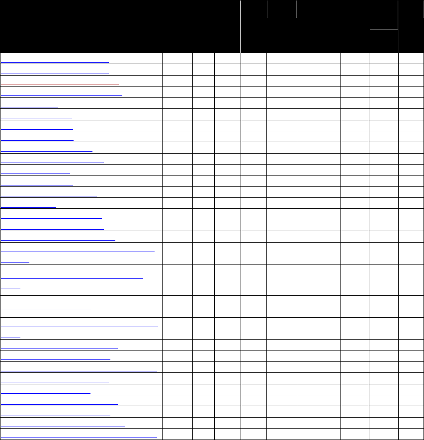
Commands Sorted by Command Name
Table 2: Commands Sorted by Command Name
Command C’less
or
C’less
+ MSR
LCD
Line
US
EMV
Protocol
CMD
SUB
CMD
Notes
Activate Transaction Command
√
√
√
√
√
2
02
01
Activate Transaction Command
√
√
√
√
√
2
02
40
Add Entry to EMV Exception List
√
√
√
√
√
2
84
09
Add Entry to EMV Revocation List
√
√
√
√
√
2
84
04
Antenna Control
√
√
√
√
√
2
28
01
Boot up Notification
√
√
√
√
√
2
14
01
Buzzer Control Long
√
√
√
√
√
2
0B
02
Buzzer Control Short
√
√
√
√
√
2
0B
01
Buzzer On/Off Command
√
n/a
√
2
F0
FE
a
Cancel Transaction Command
√
√
√
√
√
2
05
01
Check DUKPT Key
√
√
√
√
√
2
81
04
Check DUKPT Keys
√
√
√
√
√
2
81
02
Clean Torn Transaction Log
√
√
√
√
√
2
84
0F
Clear White List
√
√
√
√
√
2
2C
52
Configure Buttons Command
√
√
√
2
F0
F4
a
Contact Apply Host Response
√
√
√
2
60
12
Contact Authenticate Transaction
√
√
√
2
60
11
Contact Get MSR Data Control (Reader send
to Host) √ √ √ 2 61 03
Contact Get PIN Control (Reader send to
Host) √ √ √ 2 61 02
Contact Get Reader Status √ √ √ 2 60 14
Contact LCD Display Control (Reader send to
Host)
√ √ √ 2 61 01
Contact Remove Application Data
√
√
√
2
60
02
b
Contact Remove CA Public Key
√
√
√
2
60
09
b
Contact Remove Certification Revocation List
√
√
√
2
60
0D
b
Contact Remove Terminal Data
√
√
√
2
60
05
b
Contact Retrieve AID List
√
√
√
2
60
07
b
Contact Retrieve Application Data
√
√
√
2
60
01
b
Contact Retrieve CA Public Key
√
√
√
2
60
0A
b
Contact Retrieve CA Public Key List
√
√
√
2
60
0B
b
Contact Retrieve Certification Revocation List
√
√
√
2
60
0C
b

NEO Interface Developers Guide
5
Command C’less
or
C’less
+ MSR
LCD
Line
US
EMV
Protocol
CMD
SUB
CMD
Notes
Contact Retrieve Terminal Data
√
√
√
2
60
04
b
Contact Retrieve Transaction Result
√
√
√
2
60
13
b
Contact Set Application Data
√
√
√
2
60
03
b
Contact Set CA Public Key
√
√
√
2
60
0A
b
Contact Set Certification Revocation List
√
√
√
2
60
0E
b
Contact Set Terminal Data
√
√
√
2
60
06
b
Contact Start Transaction
√
√
√
2
60
10
b
Contact Get ICS Identification
√
√
√
2
60
15
b
Contact Remove Transaction Amount Log
√
√
√
2
60
0F
b
Contact Set ICS Identification
√
√
√
2
60
16
b
Control User Interface
√
√
√
2
01
02
Delete All CA Public Keys Protocol 1√ √ √ √ 1 24 03
Delete All CA Public Keys Protocol 2√ √ √ √ 2 D0 05
Delete All Entries for Single Index in EMV
Revocation List
√ √ √ √ 2 84 05
Delete All Entries from EMV Exception List
√ √ √ √ 2 84 0B
Delete All Entries from EMV Revocation List
√ √ √ √ 2 84 06
Delete CA Public Key Protocol 1√ √ √ √ 1 24 02
Delete CA Public Key Protocol 2√ √ √ √ 2 D0 04
Delete Configurable AID
√
√
√
√
√
2
04
04
c
Delete Configurable Group (DCG)
√
√
√
√
√
2
04
05
c
Delete Entry from EMV Exception List
√
√
√
√
√
2
84
0A
Disable Blue LED Sequence
√
√
√
√
2
F0
F6
Enable Blue LED Sequence Command
√
√
√
2
F0
F7
a
Enhanced Pass-Through Command√ √ √ √ √ 2 2C 0B
Enhanced Poll for Token
√
√
√
√
√
2
2C
0C
Exchange APDU Data
√
2C
13
Exchange Contactless Data
√
√
√
√
√
2
2C
03
Flush Track Data
√
√
√
√
√
1
17
02
Get Data encryption Key Encryption Type
√
√
√
√
√
2
C7
33
Get All AIDs
√
√
√
√
√
2
03
05
c
Get All CA Public RIDs Protocol 2
√
√
√
√
√
2
D0
06
Get All Groups (GAG)
√
√
√
√
√
2
03
07
c
Get ALL Reader Variables
√
√
√
√
√
2
09
00
Get ATR
√
2C
12
Get Button Configuration Command
√
√
√
2
F0
F5
c
Get Cable Type
√
√
√
√
√
2
32
01
Get CA Public Key Hash Protocol 2
√
√
√
√
√
2
D0
02
Get CA Public Key Protocol 2
√
√
√
√
√
2
D0
01
Get Cash Transaction Reader Risk Parameters
√
√
√
√
√
2
03
0C
Get Cashback Transaction Reader Risk
Parameters√ √ √ √ √ 2 03 0D
Get Configurable AID
√
√
√
√
√
2
03
04
c
Get Configurable Group
√
√
√
√
√
2
03
06
c
Get Configuration
√
√
√
√
√
2
03
02
Get Contact EMV L2 Kernel Checksum
√
√
√
√
√
2
29
08
Get Contact EMV L2 Kernel Version
√
√
√
√
√
2
29
06
Get Contact EMV L2 Kernel Version Detail
√
√
√
√
√
2
29
07

NEO Interface Developers Guide
6
Command C’less
or
C’less
+ MSR
LCD
Line
US
EMV
Protocol
CMD
SUB
CMD
Notes
Get Contact EMV L2 Terminal Configuration
Checksum√ √ √ √ √ 2 29 09
Get DRL Reader Risk Parameters
√
√
√
√
√
2
03
0E
Get EMV Exception List
√
√
√
√
√
2
84
0C
Get EMV Exception Log Status
√
√
√
√
√
2
84
08
Get EMV Revocation List
√
√
√
√
√
2
84
07
Get EMV Revocation Log Status
√
√
√
√
√
2
84
03
Get Firmware Full Version
√
√
√
√
√
1
29
00
Get Full Track Data
√
√
√
√
√
1
17
CD
Get Hardware Information
√
√
√
√
√
2
09
14
Get Data Encryption Enable Flag
√
√
√
√
2
C7
37
Get Data Encryption Key Variant Type
√
√
√
√
2
C7
30
Get
DUKPT Key Serial Number (KSN)
√
√
√
√
√
2
81
0A
Get Merchant Record
√
√
√
√
√
2
03
11
Get Module Version Information
√
√
√
√
√
2
09
20
Get Main Firmware Version √ √ √ √ √ 2 09 03 a
Get MSR Secure Parameters √ 2 C7 39 a
Get PCD and PICC Parameters
√
√
√
√
√
2
2C
05
Get Processor Type √ √ √ √ √ 2 09 02
Get Product Type √ √ √ √ √ 2 09 01 a
Get Remote Key Injection Timeout √ √ √ √ √ 2 C7 2E
Get Serial Number
√
√
√
2
12
01
Get Transaction Result
√
√
√
√
√
2
03
00
Get Transaction Result
√
√
√
√
√
2
03
40
Get UID of MCU
√
√
√
√
√
2
29
17
Get USB Boot Loader Version
√
√
√
√
√
2
29
04
e
Get White List
√
√
√
√
√
2
2C
51
High Level Halt Command
√
√
√
√
√
2
2C
09
LCD Display Clear Command
√
n/a
√
2
F0
F9
a
LCD Display Line 1 Message Command
√
n/a
√
2
F0
FC
a
LCD Display Line 2 Message Command
√
n/a
√
2
F0
FD
a
LED Control
√
√
√
√
√
2
0A
02
List CA Public Key IDs or RID Protocol 2
√
√
√
√
√
2
D0
07
Mifare Authenticate Block
√
√
√
√
√
2
2C
06
Mifare ePurse Command
√
√
√
√
√
2
2C
0A
Mifare Read Blocks
√
√
√
√
√
2
2C
07
Mifare Write Blocks
√
√
√
√
√
2
2C
08
NFC Commands
√
√
√
√
√
2
2C
40
Pass-through Mode Start/Stop
√
√
√
√
√
2
2C
01
PCD Single Command Exchange
√
√
√
√
√
2
2C
04
Peer To Peer Send A Message
√
√
√
√
√
2
C7
9A
Peer To Peer Receive A Message
√
√
√
√
√
2
C7
9B
Reset Torn Transaction Log√ √ √ √ √ 2 84 0E
RTC Get Date
√ √ √ √ 1 25 04 d
RTC Get Time√ √ √ √ 1 25 02 d
RTC Set Date√ √ √ √ 1 25 03 d
RTC Set Time√ √ √ √ 1 25 01 d
Set Data encryption Key Encryption Type
√
√
√
√
√
2
C7
32
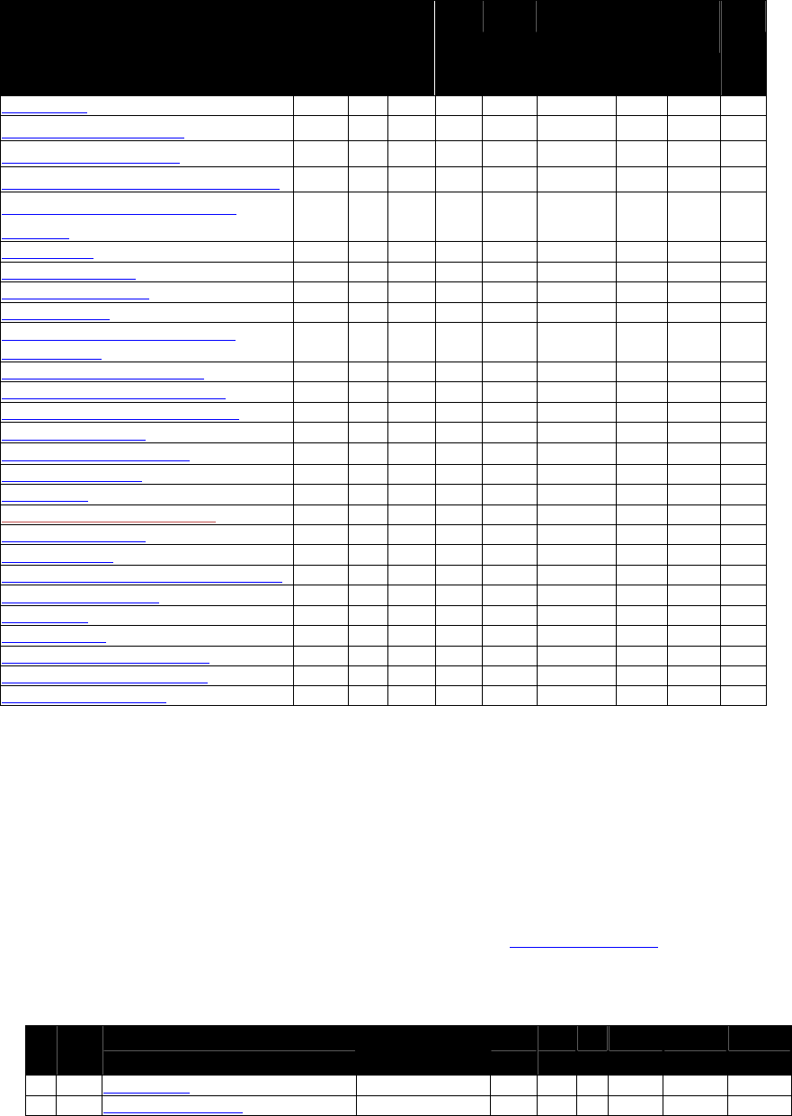
NEO Interface Developers Guide
7
Command C’less
or
C’less
+ MSR
LCD
Line
US
EMV
Protocol
CMD
SUB
CMD
Notes
Set Baud Rate
√
√
√
√
√
2
30
01
Set CA Public Key Protocol 1√ √ √ √ 1 24 01
Set CA Public key Protocol 2√ √ √ √ 2 D0 03
Set Cash Transaction Reader Risk Parameters
√ √ √ √ √ 2 04 0C
Set Cashback Transaction Reader Risk
Parameters
√ √ √ √ √ 2 04 0D
Set Cable Type
√
√
√
√
√
2
32
02
Set Configurable AID
√
√
√
√
√
2
04
02
c
Set Configurable Group
√
√
√
√
√
2
04
03
c
Set Configuration
√
√
√
√
√
2
04
00
Set Configuration Defaults and Keep
Encryption Key √ √ √ √ √ 2 04 0A
Set DRL Reader Risk Parameters
√
√
√
√
√
2
04
0E
Set Data Encryption Enable Flag
√
√
√
√
√
2
C7
36
Set Data Encryption Key Variant Type
√
√
√
√
√
2
C7
2F
Set Merchant Record
√
√
√
√
√
2
04
11
Set MSR Secure Parameters√ 2
C7
38
a
Set Parameter Defaults
2
04
09
Set Poll Mode
√
√
√
√
√
2
01
01
Set Remote Key Injection Timeout
√
√
√
√
√
2
C7
2D
Set RF Error Reporting
√
√
√
√
√
1
17
03
Set Serial Number
√
√
√
2
12
02
Set/Get Source for RTC/LCD/Buzzer/LED
√
√
√
√
√
2
01
05
Set Temporary Baud Rate
√
√
√
√
√
2
30
02
Set White List
√
√
√
√
√
2
2C
50
Stop Transaction
√
√
√
√
√
2
05
02
Turn Off Yellow LED Command
√
n/a
√
2
F0
FA
a
Turn On Yellow LED Command
√
n/a
√
2
F0
FB
a
Update Balance Command
√
√
√
√
2
03
03
a ViVOpay Vendi reader only
b Contact EMV products only
c Not in Global Reader Lite (GRL)
d Real Time Clock only
e Only applies to devices with USB
Commands Sorted by Command Number
All commands in the following table use Protocol 2 formats (see Protocol 2 Formats) except for
Get Full Track Data, Set RF Error Reporting, and Get ViVOpay Firmware Version.
Table 3: Commands Sorted by Command Number
CM
D
SUB
CMD
CommandC’less or C’less +
MSR
LCD
Line
US
EMV
Protocol
Notes
01
01
Set Poll Mode
√
√
√
√
√
2
01
02
Control User Interface
√
√
√
2

NEO Interface Developers Guide
8
CM
D
SUB
CMD
CommandC’less or C’less +
MSR
LCD
Line
US
EMV
Protocol
Notes
01
05 Set/Get Source for
RTC/LCD/Buzzer/LED
√
√
√
√
√
2
02
01
Activate Transaction Command
√
√
√
√
√
2
02
40
Activate Transaction Command
√
√
√
√
√
2
03
00
Get Transaction Result
√
√
√
√
√
2
03
40
Get Transaction Result
√
√
√
√
√
2
03
02
Get Configuration
√
√
√
√
√
2
03
03
Update Balance Command
√
√
√
√
2
03
04
Get Configurable AID
√
√
√
√
√
2
c
03
05
Get All AIDs
√
√
√
√
√
2
c
03
06
Get Configurable Group
√
√
√
√
√
2
c
03
07
Get All Groups
√
√
√
√
√
2
c
03
0C Get Cash Transaction Reader Risk
Parameters
√
√
√
√
√
2
03
0D Get Cashback Transaction Reader Risk
Parameters
√
√
√
√
√
2
03
0E
Get DRL Reader Risk Parameters
√
√
√
√
√
2
03
11
Get Merchant Record
√
√
√
√
√
2
03
40
Get Transaction Result
√
√
√
√
√
2
04
00
Set Configuration
√
√
√
√
√
2
04
02
Set Configurable AID
√
√
√
√
√
2
c
04
03
Set Configurable Group
√
√
√
√
√
2
c
04
04
Delete Configurable AID
√
√
√
√
√
2
c
04
05
Delete Configurable Group
√
√
√
√
√
2
c
04
09
Set Parameter Defaults
2
04
0A Set Configuration Defaults and Keep
Encryption Key
√
√
√
√
√
2
04
0C Set Cash Transaction Reader Risk
Parameters
√
√
√
√
√
2
04
0D Set Cashback Transaction Reader Risk
Parameters
√
√
√
√
√
2
04
0E
Set DRL Reader Risk Parameters
√
√
√
√
√
2
04
11 Set Merchant Record
√
√
√
√
√
2
05
01
Cancel Transaction Command
√
√
√
√
√
2
05
02
Stop Transaction
√
√
√
√
√
2
09
00
Get ALL Reader Variables
√
√
√
√
√
2
09
01
Get Product Type
√
√
√
√
√
2
09
02
Get Processor Type
√
√
√
√
√
2
09
03
Get Main Firmware Version
√
√
√
√
√
2
09
14
Get Hardware Information
√
√
√
√
√
2
09
20
Get Module Version Information
√
√
√
√
√
2
0A
02
LED Control
√
√
√
√
√
2
0B
01
Buzzer Control Short
√
√
√
√
√
2
0B
02
Buzzer Control Long
√
√
√
√
√
2
12
01
Get Serial Number
√
√
√
√
√
2
12
02
Set Serial Number
√
√
√
√
√
2
14
01
Boot up Notification
√
√
√
√
√
2
17
02
Flush Track Data
√
√
√
√
√
1
17
03
Set RF Error Reporting
√
√
√
√
√
1
17
CD
Get Full Track Data
√
√
√
√
√
1
18
01
Ping
√
√
√
√
√
2
24
01 Set CA Public Key
√
√
√
√
1
24
02 Delete CA Public Key
√
√
√
√
1

NEO Interface Developers Guide
9
CM
D
SUB
CMD
CommandC’less or C’less +
MSR
LCD
Line
US
EMV
Protocol
Notes
24
03
Delete All CA Public Keys
√
√
√
√
1
25
01
RTC Set Time
√
√
√
√
1
d
25
02 RTC Get Time
√
√
√
√
1
d
25
03 RTC Set Date
√
√
√
√
1
d
25
04 RTC Get Date
√
√
√
√
1
d
28
01
Antenna Control
√
√
√
√
√
2
29
00
Get Version Protocol 2
√
√
√
√
√
2
29
00
Get Firmware Full Version
√
√
√
√
√
1
29
04
Get USB Boot Loader Version
√
√
√
√
√
2
e
29
06
Get Contact EMV L2 Kernel Version
√
√
2
29
07 Get Contact EMV L2 Kernel Version
Detail
√
√
2
29
08
Get Contact EMV L2 Kernel Checksum
√
√
2
29
09 Get Contact EMV L2 Terminal
Configuration Checksum
√
√
2
29
17
Get UID of MCU
√
√
2
32
01
Get Cable Type
√
√
√
√
√
2
32
02
Set Cable Type
√
√
√
√
√
2
2C
01
Pass-Through Mode Start/Stop
√
√
√
√
√
2
2C
02
Poll for Token
√
√
√
√
√
2
2C
03
Exchange Contactless Data
√
√
√
√
√
2
2C
04
PCD Single Command Exchange
√
√
√
√
√
2
2C
05
Get PCD and PICC Parameters
√
√
√
√
√
2
2C
06
Mifare Authenticate Block
√
√
√
√
√
2
2C
07
Mifare Read Blocks
√
√
√
√
√
2
2C
08
Mifare Write Blocks
√
√
√
√
√
2
2C
09
High Level Halt Command
√
√
√
√
√
2
2C
0A
Mifare ePurse Command
√
√
√
√
√
2
2C
0B
Enhanced Pass-Through Command
√
√
√
√
√
2
2C
0C
Enhanced Poll for Token
√
√
√
√
√
2
2C
12
Get ATR
√
2
2C
13
Exchange APDU Data
√
2
2C
40
NFC Commands
√
2
2C
50
Set White List
√
√
√
√
√
2
2C
51
Get White List
√
√
√
√
√
2
2C
52
Clear White List
√
√
√
√
√
2
30
01
Set Baud Rate
√
√
√
√
√
2
30
02
Set Temporary Baud Rate
√
√
√
√
√
2
60
01
Contact Retrieve Application Data
√
√
√
2
60
02
Contact Remove Application Data
√
√
√
2
60
03
Contact Set Application Data
√
√
√
2
60
04
Contact Retrieve Terminal Data
√
√
√
2
60
05
Contact Remove Terminal Data
√
√
√
2
60
06
Contact Set Terminal Data
√
√
√
2
60
07
Contact Retrieve AID List
√
√
√
2
60
08
Contact Retrieve CA Public Key
√
√
√
2
60
09
Contact Remove CA Public Key
√
√
√
2
60
0A
Contact Set CA Public Key
√
√
√
2
60
0B
Contact Retrieve CA Public Key List
√
√
√
2
60
0C Contact Retrieve Certification
Revocation List
√
√
√
2

NEO Interface Developers Guide
10
CM
D
SUB
CMD
CommandC’less or C’less +
MSR
LCD
Line
US
EMV
Protocol
Notes
60
0D Contact Remove Certification
Revocation List
√
√
√
2
60
0E
Contact Set Certification Revocation List
√
√
√
2
60
0F Contact Remove Transaction Amount
Log
√
√
√
2
60
10
Contact Start Transaction
√
√
√
2
60
11
Contact Authenticate Transaction
√
√
√
2
60
12
Contact Apply Host Response
√
√
√
2
60
13
Contact Retrieve Transaction Result
√
√
√
2
60
14
Get Contact Reader Status
√
√
√
2
60
15
Contact Get ICS Identification
√
√
√
2
60
16
Contact Set ICS Identification
√
√
√
2
61
01 Contact LCD Display Control (Reader
send to Host)
√
√
√
2
61
02 Contact Get PIN Control (Reader send
to Host)
√
√
√
2
61
03 Contact Get MSR Data Control (Reader
send to Host)
√
√
√
2
81
02
Check DUKPT Keys
√
√
√
√
√
2
81
04
Check DUKPT Key
√
√
√
√
√
2
81
0A
Get DUKPT Key Serial Number (KSN)
√
√
√
√
√
2
84
03
Get EMV Revocation Log Status
√
√
√
√
√
2
84
04
Add Entry to EMV Revocation List
√
√
√
√
√
2
84
05 Delete All Entries for Single Index in
EMV Revocation List
√
√
√
√
√
2
84
06 Delete All Entries from EMV
Revocation List
√
√
√
√
√
2
84
07
Get EMV Revocation List
√
√
√
√
√
2
84
08
Get EMV Exception Log Status
√
√
√
√
√
2
84
09
Add Entry to EMV Exception List
√
√
√
√
√
2
84
0A
Delete Entry from EMV Exception List
√
√
√
√
√
2
84
0B
Delete All Entries from EMV Exception
List
√
√
√
√
√
2
84
0C
Get EMV Exception List
√
√
√
√
√
2
84
0D Delete an Entry from EMV Revocation
List
√
√
√
√
√
2
84
0E
Reset Torn Transaction Log
√
√
√
√
√
2
84
0F
Clean Torn Transaction Log
√
√
√
√
√
2
C7
2D
Set Remote Key Injection Timeout
√
√
√
√
√
2
C7
2E
Get Remote Key Injection Timeout
√
√
√
√
√
2
C7
2F
Set Data Encryption Key Variant Type
√
√
√
√
√
2
C7
30
Get Data Encryption Key Variant Type
√
√
√
√
√
2
C7
32 Set Data encryption Key Encryption
Type
√
√
√
√
√
2
C7
33 Get Data encryption Key Encryption
Type
√
√
√
√
√
2
C7
36
Set Data Encryption Enable Flag
√
√
√
√
√
2
C7
37
Get Data Encryption Enable Flag
√
√
√
√
√
2
C7
38
Set MSR Secure Parameters
√
2
C7
39
Get MSR Secure Parameters
√
2
C7
9A
Peer To Peer Send A Message
√
√
√
√
√
2
C7
9B
Peer To Peer Receive A Message
√
√
√
√
√
2
D0
01
Get CA Public Key Protocol 2
√
√
√
√
√
2
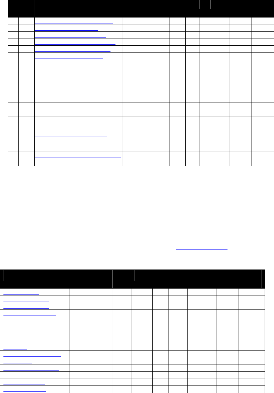
NEO Interface Developers Guide
11
CM
D
SUB
CMD
CommandC’less or C’less +
MSR
LCD
Line
US
EMV
Protocol
Notes
D0
02
Get CA Public Key Hash Protocol 2
√
√
√
√
√
2
D0
03
Set CA Public Key Protocol 2
√
√
√
√
√
2
D0
04
Delete CA Public Key Protocol 2
√
√
√
√
√
2
D0
05
Delete All CA Public Keys Protocol 2
√
√
√
√
√
2
D0
06
Get All CA Public RIDs Protocol 2
√
√
√
√
√
2
D0
07 List CA Public Key IDs or RID
Protocol 2
√
√
√
√
√
2
F0
00 Set PMC Status
√
√
√
√
√
2
F0
01
Get PMC Status
√
√
√
√
√
2
F0
02
Get Battery Level
√
√
√
√
√
2
F0
0F
Shut Off the Power
√
√
√
√
√
2
F0
F4
Configure Buttons Command
√
√
√
2
a
F0
F5
Get Button Configuration Command
√
√
√
2
a
F0
F6
Disable Blue LED Sequence
√
n/a
√
2
a
F0
F7
Enable Blue LED Sequence Command
√
n/a
√
2
a
F0
F9
LCD Display Clear Command
√
n/a
√
2
a
F0
FA
Turn Off Yellow LED Command
√
n/a
√
2
a
F0
FB
Turn On Yellow LED Command
√
n/a
√
2
a
F0
FC
LCD Display Line 1 Message Command
√
n/a
√
2
a
F0
FD
LCD Display Line 2 Message Command
√
n/a
√
2
a
F0
FE
Buzzer On/Off Command
√
n/a
√
2
a
a ViVOpay Vendi reader only
c Not in Global Reader Lite (GRL)
d Real Time Clock only
e Only applies to devices with USB
Pass-Through Command Table
All commands in the following table use Protocol 2 formats (see Protocol 2 Formats).
Table 4: Pass-Through Command Table
Command C’less or
C’less + MSR
LCD
Line
US
EMV
Protocol
CMD
SUB
CMD
Antenna Control
√
√
√
√
√
2
28
01
Buzzer Control Long
√
√
√
√
√
2
0B
02
Buzzer Control Short
√
√
√
√
√
2
0B
01
Enhanced Pass-Through
Command
√
√
√
√
√
2
2C
0B
Enhanced Poll for Token
√
√
√
√
√
2
2C
0C
Exchange Contactless Data
√
√
√
√
√
2
2C
03
Get PCD and PICC
Parameters
√
√
√
√
√
2
2C
05
High Level Halt Command
√
√
√
√
√
2
2C
09
LED Control
√
√
√
√
√
2
0A
02
Mifare Authenticate Block
√
√
√
√
√
2
2C
06
Mifare ePurse Command
√
√
√
√
√
2
2C
0A
Mifare Read Blocks
√
√
√
√
√
2
2C
07
Mifare Write Blocks
√
√
√
√
√
2
2C
08
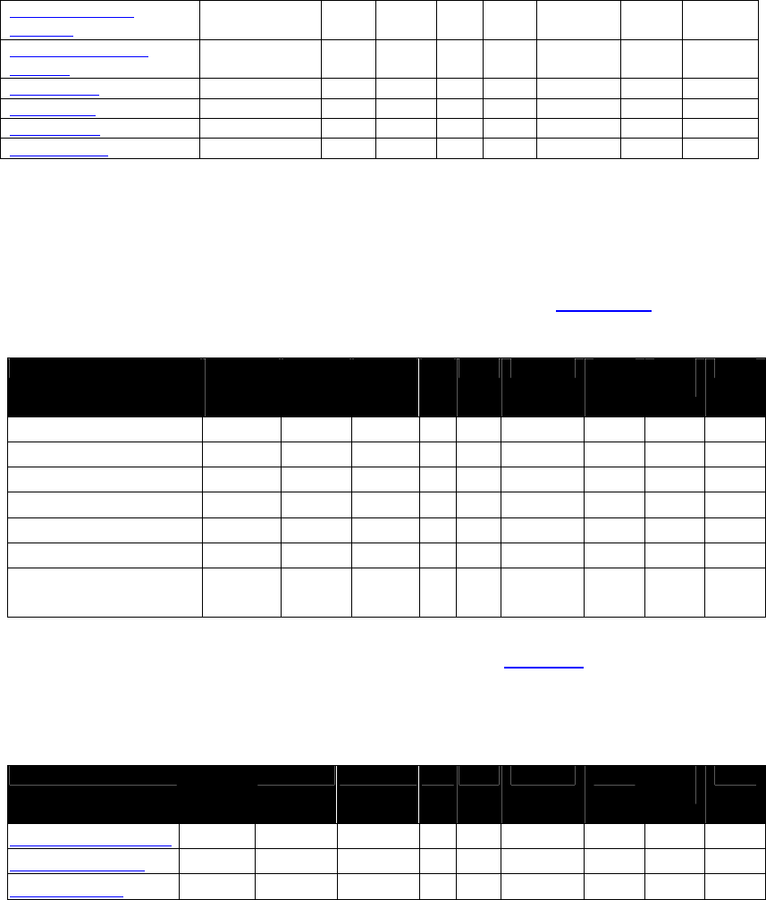
NEO Interface Developers Guide
12
Pass-Through Mode
Start/Stop
√
√
√
√
√
2
2C
01
PCD Single Command
Exchange
√
√
√
√
√
2
2C
04
Poll for Token
√
√
√
√
√
2
2C
02
Set White List
√
√
√
√
√
2
2C
50
Get White List
√
√
√
√
√
2
2C
51
Clear White List
√
√
√
√
√
2
2C
52
EMV Key Manager Command Tables
The preferred method of accessing the Certificate Authority public keys is to
use the following commands in the Protocol 2 format: (see Protocol 2)
Table 5: EMV Key Management – Protocol 2
Command C’less or
C’less +
MSR
LCD Line US
EMV
Protocol
CMD SUB
CMD
Notes
Get CA Public Key
√
√
√
√
2
D0
01
Get CA Public Key Hash
√
√
√
√
2
D0
02
Set CA Public Key
√
√
√
√
2
D0
03
Delete CA Public Key
√
√
√
√
2
D0
04
Delete All CA Public Keys
√
√
√
√
2
D0
05
Get All CA Public RIDs
√
√
√
√
2
D0
06
List CA Public Key IDs for
RID
√
√
√
√
2
D0
07
All commands in the following table use Protocol 1 formats (see Protocol 1). These commands
are included for backward compatibility. New development should use Protocol 2 commands
listed above.
Table 6: EMV Key Management - Protocol 1
CommandC’less or
C’less +
MSR
LCDLineUS
EMV
Protocol
CMDSUB
CMD
Notes
Delete All CA Public Keys
√
√
√
√
1
24
03
Delete CA Public Key
√
√
√
√
1
24
02
Set CA Public Key
√
√
√
√
1
24
01

NEO Interface Developers Guide
13
Status Codes
The tables in this section define status codes for Protocol 1 and Protocol 2. Note that Protocol 1
is deprecated.
Status Codes for Protocol 1
Table 7: Protocol 1 Status Codes
Status Code Status
00h
OK
01h
Incorrect Frame Tag
02h
Incorrect Frame Type
03h
Unknown Frame Type
04h
Unknown Command
05h
Unknown Sub-Command
06h
CRC Error
07h
Failed
08h
Timeout
0Ah
Incorrect Parameter
0Bh
Command Not Supported
0Ch
Sub-Command Not Supported
0Dh
Parameter Not Supported / Status Abort Command
0Eh
Command not Allowed
0Fh
Sub-Command Not Allowed
Status Codes for Protocol 2
Table 8: Protocol 2 Status Codes
Status Code Status
00h
OK
01h
Incorrect Header Tag
02h
Unknown Command
03h
Unknown Sub-Command
04h
CRC Error in Frame
05h
Incorrect Parameter
06h
Parameter Not Supported
07h
Mal-formatted Data
08h
Timeout
0Ah
Failed / NACK
0Bh
Command not Allowed
0Ch
Sub-Command not Allowed

NEO Interface Developers Guide
14
Status Code Status
0Dh
Buffer Overflow (Data Length too large for reader buffer)
0Eh
User Interface Event
10h
Need clear firmware(apply in boot loader only)
11h
Communication type not supported, VT-1, burst, etc.
Need encrypted firmware (apply in boot loader only)
12h
Secure interface is not functional or is in an intermediate state.
13h
Data field is not mod 8
14h
Pad 0x80 not found where expected
15h
Specified key type is invalid
16h
Could not retrieve key from the SAM (InitSecureComm)
17h
Hash code problem
18h
Could not store the key into the SAM (InstallKey)
19h
Frame is too large
1Ah
Unit powered up in authentication state but POS must resend the
InitSecureComm command
1Bh
The EEPROM may not be initialized because SecCommInterface does not
make sense
1CH
Problem encoding APDU
Module-Specific Status Codes1
20h
Unsupported Index (ILM)
SAM Transceiver error – problem communicating with the SAM (Key Mgr)
21h
Unexpected Sequence Counter in multiple frames for single bitmap (ILM)
Length error in data returned from the SAM (Key Mgr)
22h
Improper bit map (ILM)
23h
Request Online Authorization
24h
ViVOCard3 raw data read successful
25h
Message index not available (ILM)
ViVOcomm activate transaction card type (ViVOcomm)
26h
Version Information Mismatch (ILM)
27h
Not sending commands in correct index message index (ILM)
28h
Time out or next expected message not received (ILM)
29h
ILM languages not available for viewing (ILM)
2Ah
Other language not supported (ILM)
31h
Request Online PIN
41h – 4Fh
Module-specific errors for Key Manager
50h
Auto-Switch OK
51h
Auto-Switch failed
60h
Data not exist
61h
Data Full
62h
Write Flash Error
63h
Ok and have next command
70h
Antenna Error
1
Status codes in this range are “module-specific” so that their values can be re-used by different modules. The
meaning of these codes may depend on which command is being issued. An exception is 23h, which is used generally.
NEO Interface Developers Guide
15
Status Code Status
Note for Kiosk III:
If antenna is disconnected when Activate Transaction(02-01)
command is not received, reader will keep beeping until the
antenna is connected correctly.
If Activate Transaction(02-01) command is received, and
during the polling time, antenna is disconnected, reader will
waiting to the end of polling time, and return status code
08h(Time Out), then keep beeping until the antenna is
connected correctly.
Reader will response 70h as status code once Activate
Transaction(02-01) command is received when antenna is
disconnected.
80h
Use another card
81h
Insert or swipe card
90h
Data encryption Key does not exist
91h
Data encryption Key KSN exhausted
Error Codes
Table 9: Error Codes
Error
Code Description Reason for Error and Suggested Error Handling
00h
No Error
None.
01h
Out of Sequence
Command
Reader did not receive commands in the correct order. Correct the Terminal
application to send serial commands in the correct sequence.
02h Go to Contact
Interface
The contactless transaction failed.
If the reader supports a contact interface, advise the user to complete the
transaction on the contact interface.
Previously, this error code was used if the reader supported another
interface (beside the contact interface). Integrators should use error code
04h Go to Other Interface instead. The previous use has been deprecated.
03h Transaction
Amount is Zero
If the transaction amount is zero and the terminal is “an offline only terminal”
then reader needs to terminate the transaction.
04h Go To Other
Interface
The transaction has failed.
If the reader supports another interface, advise the user to complete the
transaction on the other interface.

NEO Interface Developers Guide
16
Error
Code Description Reason for Error and Suggested Error Handling
05h Go To Nearby
Interface
The transaction has failed.
If there is another nearby contact interface, advise the user to complete the
transaction on the nearby contact interface. This situation might be a case
where there are multiple pay stations, but only one of them has a contact
interface.
06h Go To MagStripe
Interface
The transaction has failed.
If the reader has a MagStripe interface, advise the user to complete the
transaction using the MagStripe interface.
20h Card returned
Error Status
Card returned SW1SW2 not equal to 9000 hex. Value of the SW1SW2 bytes from
the Card is returned in the Data portion of the Response Frame. Details of what
the SW1SW2 codes mean for each RF State are Card dependent and are out of
the scope of this document.
How the terminal handles this error depends on when the error occurs in the
transaction flow. The RF State Code (see section on RF State Codes) indicates
the transaction state when the error occurred. Suggested error handling for
individual RF State Codes is given below:
RF State Code = PPSE:
If RF State Code = SELECT:
If RF State Code = GPO:
If RF State Code = READ RECORD:
If RF State Code = GET DATA (Ticket):
If RF State Code = GET DATA (Ticketing Profile):
If RF State Code = GET DATA (Balance):
If RF State Code = PUT DATA (Ticket):
The terminal can retry the transaction or abandon it.
If RF State Code = GEN AC:
For Credit transactions:
The terminal can retry the transaction or abandon it.
21h
Collision Error
There was more than one contactless card in the reader’s range.
22h
Amount Over
Maximum Limit
The Transaction Amount is greater than Terminal Contactless Transaction Limit
(FFF1).
23h Request Online
Authorization
If the Transaction Amount is greater than the Balance on the card but is less
than the Terminal Contactless Transaction Limit (FFF1), the reader sends this
error code back to the terminal along with other information needed by the
acquirer to format an online authorization request.
24h
Card
Communication
Error
A communication error occurred while interacting with the card. An example
might be the card was removed from the field.
25h Card Blocked
If the card is not supported by the reader according to the value of parameter
Application Capability (FFF3) this error code is sent to the terminal.
26h Card Expired
This error code is sent to the terminal if the current date of the reader is
greater than the expiration date of the card. This status code is only valid for
qVSDC cards.
27h Unsupported
Card
Card presented to the reader is of a type that is not supported by the reader.
This could be due to presenting a card with an AID that is not reco
gnized by the
reader.

NEO Interface Developers Guide
17
Error
Code Description Reason for Error and Suggested Error Handling
30h Card did not
respond
Card was removed from the field or there was a Communication Error
preventing the card response from reaching the reader. How the terminal
handles this error depends on when in the transaction the error occurred. The
RF State Code (see section on RF State Codes) indicates the transaction state
when the error occurred. Suggested error handling for each RF State Code is
given below:
RF State Code = PPSE:
The terminal can retry the transaction or abandon it.
If RF State Code = SELECT:
The terminal can retry the transaction or abandon it.
If RF State Code = GPO:
The terminal can retry the transaction or abandon it.
If RF State Code = READ RECORD:
The terminal can retry the transaction or abandon it.
If RF State Code = GEN AC:
For Credit transactions:
The terminal can retry the transaction or abandon it.
If RF State Code = GET DATA (Ticket):
If RF State Code = GET DATA (Ticketing Profile):
If RF State Code = GET DATA (Balance):
If RF State Code = PUT DATA (Ticket):
41h
Data Element
Missing
A mandatory/required data element was missing from the card.
42h
Card Generated
AAC
The card declined the transaction by sending an AAC instead of a TC.
43h Card Generated
ARQC
This error code would be returned if the card generated an ARQC and the
terminal/reader was configured as “Offline Only”; therefore the card was
DECLINED.
44h
SDA/DDA Failed
(Not Supported
by Card)
Card did not indicate support for the correct authentication method and date
authentication failed. For Visa, when DDA is required, the card must indicate
support for DDA in AIP. If this support is not indicated then the transaction fails
and this error code is returned.
50h
SDA/DDA/CDDA
Failed (CA
Public Key)
Data Authentication failed due to missing CA Public Key.
Retrying the transaction does not correct the error until the missing CA Public
Key problem is corrected via Key Management commands.
51h
SDA/DDA/CDDA
Failed (Issuer
Public Key)
Data Authentication failed due to a problem in recovering the Issuer Public Key
from the card data. Data on the card may be incorrect or the reader has the
wrong CA Public Key.
The transaction continues to fail until the Issuer Public Key and the CA Public
Key are correct.
52h
SDA Failed
(SSAD)
Data Authentication failed during SSAD. Retrying the transaction does not
correct the error.
53h
DDA/CDDA
Failed (ICC
Public Key)
Data Authentication failed during attempted recovery of ICC Public Key.
Retrying the transaction does not correct the error.
54h
DDA/CDDA
Failed (Dynamic
Signature
Verification)
Data Authentication failed during Dynamic Signature Verification. Retrying the
transaction does not correct the error:
At this point, the amount has been deducted from the Card Balance.
55h
Processing
Restrictions
Failed
The Processing Restrictions step as defined in EMV Specifications failed. This
could be due to incorrectly set configuration. Retrying the transaction does not
correct the error until the EMV configuration is corrected.

NEO Interface Developers Guide
18
Error
Code Description Reason for Error and Suggested Error Handling
56h
Terminal Risk
Management
(TRM) Failed
The Terminal Risk Management step as defined in EMV Specifications failed.
This could be due to incorrectly set configuration. Retrying the transaction
does not correct the error until the EMV configuration is corrected.
57h
Cardholder
Verification
Failed
The Cardholder Verification step as defined in EMV Specifications failed. This
could be due to incorrectly set configuration. Retrying the transaction does not
correct the error until the EMV configuration is corrected.
58h
Terminal Action
Analysis (TAA)
Failed
The Terminal Action Analysis step as defined in EMV Specifications failed. This
could be due to incorrectly set configuration. Retrying the transaction does not
correct the error until the EMV configuration is corrected.
61h
SD Memory Error
This error is reported only when trying to retrieve Transaction Logs. This error
is never reported during a transaction.
62h Generic Error
This is a generic / general error that is reported when a more specific reason
for the error is not known.
73h
Torn
Transaction Log
Error
An error occurred while attempting to clean the torn transaction log. This
might occur if the reader could not read the time and date from the real time
clock.
80h
No Merchants
have been
configured
This error usually occurred while MerchantID is empty.
81h
TLV Parse
Failure
This error usually occurred while fail to TLV parsing card response data.
82h
Merchant Data
Error
This error usually occurred while no merchant data returned from card.
83h
System Memory
Error
This error usually occurred while fail to read or write system memory.
84h
Application Skip
Error
This error usually occurred while configuration isn’t consistent on whether or
not to skip payment application
85h
Application
Version Error
This error usually occurred while application version number is incorrect.
If an error occurs during a transaction and the terminal determines that the reader must
perform exception processing, then the terminal must retry the transaction until the transaction
has been completed successfully or the terminal decides to abort it. The retries must be
continued even if successive transactions fail with conditions that do not require exception
processing. This must be done to allow the reader to complete exception processing (even if
there are failures during exception processing).
Under certain conditions, such as when a customer walks away or there is a problem with the
card, the terminal may want to abort the retries even if the reader has not been able to
complete exception processing. How and when the terminal stops retrying is out of the scope of
this document.
RF State Codes
For some Error Codes, the RF State Code indicates the exact Reader-Card command that failed.
This helps determine the exact place where the failure occurred.

NEO Interface Developers Guide
19
Table 10: RF State Codes
State
Code RF State Description
00h
None
RF State Code not available
01h
PPSE
Error occurred during PPSE command
02h
SELECT
Error occurred during SELECT command
03h
GPO
Error occurred during GET PROCESSING OPTIONS command
04h
READ RECORD
Error occurred during READ RECORD command
05h
GEN AC
Error occurred during GEN AC command
06h
CCC
Error occurred during CCC command
07h
IA
Error occurred during IA command
08h
SDA
Error occurred during SDA processing
09h
DDA
Error occurred during DDA processing
0ah
CDA
Error occurred during CDA processing
0bh
TAA
Error occurred during TAA processing
0ch
UPDATE RECORD
Error occurred during UPDATE RECORD command
10h GET DATA (Ticket)
Error occurred during GET DATA command to retrieve the
Ticket
11h GET DATA (Ticketing Prof)
Error occurred during GET DATA command to retrieve the
Ticketing Profile
12h GET DATA (Balance)
Error occurred during GET DATA command to retrieve the
Balance
13h
GET DATA (All)
Error occurred during GET DATA command to retrieve all data
20h PUT DATA (Ticket)
Error occurred during PUT DATA command to retrieve the
Ticket
NEO Interface Developers Guide
20
3.0 Serial Communication Interfaces
This section discusses the physical interfaces through which the terminal
communicates with the ViVOpay reader. All of the readers have an RS232/ USB
Serial Interface.
Note: Please don't plug in/out serial communication interfaces during the device power on,
that might cause unstable behavior, The reader is not certified to work properly.
RS232 Serial Interface
Port Settings
To communicate with the ViVOpay reader, set the terminal’s serial communication parameters
to the values listed below.
Table 11: Serial Port Settings
Parameter Value
Baud Rate
19200 bps (default value for all but Vendi)
9600 bps (default value for Vendi)
Data Bits
8
Stop Bits
1
Parity
None
Out CTS Flow
Disabled
Out DSR Flow
Disabled
DTR Control
Disabled
RTS Control
Disabled
XON/XOFF
Disabled
Flow Control
None
Basic Communication
The ViVOpay reader and the POS terminal communicate by exchanging Command-Response
Frames. The terminal always initiates communication by sending a Command Frame and
ViVOpay responds by sending a Response Frame. What frames are exchanged depends on the
command and the protocol used. There are two command/response protocols. Protocol 1 uses
separate Data Frames and ACK/NACK responses. Protocol 2 is simplified by including data within
the Command/Response Frames.
Timeouts
The ViVOpay reader does not timeout while trying to receive a command. There is no maximum
inter-character delay. As a result, command frames with length errors may appear to “hang”.
A subsequent command that does not contain a length error can be received successfully.

NEO Interface Developers Guide
21
Once the ViVOpay reader has received a command, the time required to respond to the terminal
varies from command to command, depending on what processing is required.
During a transaction, the Activate (02-01) command may specify a timeout value. The reader
will continue to poll until it starts to process a transaction, or the specified timeout period has
elapsed. The transaction may not complete within the timeout period.
USB HID Interface
ViVOpay readers can communicate with the terminal using a RS232 Serial link and/or a USB HID
link.
All ViVOpay commands sent over the USB HID interface are encapsulated in the following
protocol.
Note: The maximum length for any command or response is 1500 bytes since this is the size
of the command FIFO.
HID Report Format
All HID reports sent to or received from the ViVOpay are 64 bytes long. The first byte of the
frame is a single byte Report ID number. The remaining 63 bytes carry the report payload. Any
reports with less than 63 bytes of command or response data are padded with NULL bytes (00h)
to make them 63 bytes long.
ViVOpay commands and responses are sent over the USB bus in 63-byte frames. Byte ordering in
the USB frame is the same as if the command were sent over the serial port. In other words, the
“ViVOtech2” command tag always starts in the second byte of the first report containing the
command, just after the Report ID.
There are four defined report IDs used in this protocol: 1, 2, 3, and 4. Undefined report IDs are
silently ignored.
3.1.1.1 Report ID 1
ID 1 frames are used when a complete command or response is 63 bytes or less. As soon as the
host or device receives a Report ID 1 frame, it should parse the report data to extract the
command or response.
3.1.1.2 Report ID 2
ID 2 frames are used when a complete command or response is more than 63 bytes long and
cannot fit in a single report. The Report ID 2 frame contains the first 63 bytes of the command.
So the “ViVOtech2” command tag is only present in Report IDs 1 or 2. The Report ID 2 frames
always contain 63 bytes of valid data with no padding bytes since the command is more than 63
bytes long.

NEO Interface Developers Guide
22
3.1.1.3 Report ID 3
ID 3 frames are continuation frames. For any command or response that is more than 126 bytes
long, the middle frames of the response are sent with a report ID of 3. Any frame received with
a report ID 3 is ignored unless it is preceded by a report with an ID of 2 or 3. The Report ID 3
frames should always contain 63 bytes of valid data with no padding bytes.
3.1.1.4 Report ID 4
ID 4 frames mark the end of multi-report commands. Any padding needed to make the command
a multiple of 63 bytes should be placed in this report. Any frame received with a report ID 4 is
ignored unless it is preceded by a report with an ID of 2 or 3. As soon as the host or device
receives a valid Report ID 4 frame, it should parse the report data to extract the command or
response.
The exception to the rule of only adding pad bytes to reports with ID of 1 or 4 is debug test
frames. Surrounding a command with pad bytes to make the command span multiple reports is
valid for testing the multi-report handling of the host and device software. This must be avoided
in deployed code since it slows command processing times.
Sample Single Report Command and Response
Ping Command Report
01
“V”
“i”
“V”
“O”
“t”
“e”
“c”
“h”
“2”
00
18
01
00
00
B3
CD
00 00
00 00 00
00 00 00 00 00
00 00
00 00
00
00 00 00
00 00 00
00 00 00 00 00
00 00
00 00
00
00 00 00
00 00 00
00 00 00 00 00
00 00
00 00
00
The pad bytes are marked with blue text in this example.
Ping Response Report
01
“V”
“i”
“V”
“O”
“t”
“e”
“c”
“h”
“2”
00
18
00
00
00
FA
83
00 00 00 00 00 00 00 00 00 00 00 00 00 00 00
00 00 00 00 00 00 00 00 00 00 00 00 00 00 00 00
00 00 00 00 00 00 00 00 00 00 00 00 00 00 00 00
The pad bytes are marked with blue text in this example.
The serial port version of this command and response would be: (Data bytes in Hex format)
Command: 56 69 56 4F 74 65 63 68 32 00 18 01 00 00 B3 CD
Response: 56 69 56 4F 74 65 63 68 32 00 18 00 00 00 FA 83

NEO Interface Developers Guide
23
Data Frames
Byte 0-8
Byte 9
Byte 10
Byte 11
…
Byte n+10
Byte n+11
Byte n+12
Frame Tag
Frame
Type Data 0 Data 1 … Data n
CRC
MSB if from
ViVOpay.
LSB if from
Terminal.
CRC
LSB if from
ViVOpay.
MSB if from
Terminal.
ViVOtech\0
‘D’
…
Direction: Both Ways (depending on Command). Variable Length (n = 1 … 244).
Sample Single Report Command with Multiple Report Response
Get Configuration Command Report
01
“V”
“i”
“V”
“O”
“t”
“e”
“c”
“h”
“2”
00
03
02
00
00
5B
91
00 00 00 00 00 00 00 00 00 00 00 00 00 00 00
00 00 00 00 00 00 00 00 00 00 00 00 00 00 00 00
00 00 00 00 00 00 00 00 00 00 00 00 00 00 00 00
The pad bytes are marked with blue text in this example.
Get Configuration response reports
1st Response Report
02
“V”
“i”
“V”
“O”
“t”
“e”
“c”
“h”
“2”
00
03
00
00
C2
FF
E4
01
00
9F
02
06
00
00
00
00
00
01
9F
03
06
00
00
00
00
00
00
DF
63
01
00
DF
64
01
01
DF
65
01
00
DF
66
01
00
FF
F0
03
00
00
00
FF
F2
08
30
30
2nd Response Report
03
30
30
30
30
30
30
FF
F3
02
03
FF
FF
F7
01
02
FF
F9
01
03
FF
FA
02
03
E8
9A
03
00
01
04
9F
21
03
05
13
54
9C
01
00
5F
2A
02
08
40
9F
09
02
00
02
9F
1A
02
08
40
9F
1B
04
00
00
17
70
9F
33
03
3rd Response Report
03
00
08
E8
9F
35
01
22
9F
40
05
60
00
00
30
00
9F
66
04
A0
00
00
00
FF
F1
06
00
00
00
01
00
00
FF
F4
03
01
00
01
FF
F5
06
00
00
00
00
80
00
FF
F8
01
00
FF
FB
01
00
FF
FC
01
00
FF
FD
05
F8
50
4th and Final Response Report

NEO Interface Developers Guide
24
04
AC
F8
00
FF
FE
05
F8
50
AC
A0
00
FF
FF
05
00
00
00
00
00
72
56
00 00 00 00 00 00 00 00 00 00
00 00 00 00 00 00 00 00 00 00 00 00 00 00 00 00
00 00 00 00 00 00 00 00 00 00 00 00 00 00 00 00
The pad bytes are marked with blue text in this example.
Note: The response to this command changes each time the command is sent since it
includes the current time and date.
The serial port version of this command and response would be: (Data bytes in Hex format)
Command: 56 69 56 4F 74 65 63 68 32 00 03 02 00 00 5B 91
Response: 56 69 56 4F 74 65 63 68 32 00 03 00 00 C2 FF E4 01 00 9F 02
06 00 00 00 00 00 01 9F 03 06 00
00 00 00 00 00 DF 63 01 00 DF 64 01 01 DF 65 01
00 DF 66 01 00 FF F0 03 00 00 00 FF F2 08 30 30
30 30 30 30 30 30 FF F3 02 03 FF FF F7 01 02
FF F9 01 03 FF FA 02 03 E8 9A 03 00 01 04 9F 21
03 05 13 54 9C 01 00 5F 2A 02 08 40 9F 09 02 00
02 9F 1A 02 08 40 9F 1B 04 00 00 17 70 9F 33 03
00 08 E8 9F 35 01 22 9F 40 05 60 00 00 30 00
9F 66 04 A0 00 00 00 FF F1 06 00 00 00 01 00 00
FF F4 03 01 00 01 FF F5 06 00 00 00 00 80 00 FF
F8 01 00 FF FB 01 00 FF FC 01 00 FF FD 05 F8 50
AC F8 00 FF FE 05 F8 50 AC A0 00 FF FF 05 00
00 00 00 00 72 56
Error Handling at Report Level
1. Any report with ID of 1 is processed as soon as it is received. All other unprocessed reports
are discarded.
2. Any report with an ID of 2 causes all other unprocessed reports to be discarded.
3. Any report with an ID of 3 is discarded unless the previous report had an ID of 2 or 3. If the
previous report ID 3 was discarded then this report also is discarded.
4. Any report with an ID of 4 is discarded unless the previous report had an ID of 2 or 3. If the
previous report had an ID of 3 and was discarded then this report also is discarded. If the
report ID 4 frame is retained, then all retained reports are processed.
Processing of reports means passing the concatenated Data Frames contained in the reports to
the command handler. The report ID bytes must be discarded when concatenating the report
Data Frames.
An alternate way to handle the rules for report IDs 3 and 4 is to set a flag when a report with an
ID of 2 is received and reset the flag when a report with an ID of 1 is received or an ID of 4 is
finished processing. Reports with IDs of 3 or 4 are only kept when the flag is set.
NEO Interface Developers Guide
25
Error Handling at Command Level
The error handling at the command level remains as it is currently implemented for serial port
commands.
Incomplete commands are silently ignored when the reception times out. This does not occur for
commands received over the USB HID interface unless a complete report is dropped, resulting in
missing data for the command. The normal USB handshaking is expected to prevent this.
A bad CRC value for the encapsulated command returns a bad CRC response to the command.
An unknown command or subcommand code results in an unknown command or unknown
subcommand Response Frame.
If the host does not receive any response to a command it should retry the command.
If the host receives a bad CRC response to a command it should retry the command. This is not
expected to occur when using USB since it includes a layer of error handling.
NEO Interface Developers Guide
26
4.0 ViVOpay Communication Protocols
There are two main types of protocols: Protocol 1 and Protocol 2. Protocol 2 is the preferred
method of communicating between the terminal/POS and a ViVOpay reader. Protocol 1 is
retained for backward compatibility with older terminal/POS applications.
In addition to the two main protocols, there are modes of communication that are extensions of
the protocols. These modes provide flexibility in the control of the ViVOpay reader:
Pass-through mode allows the terminal/POS application to interact directly with the
contactless ISO 7816 cards.
Burst Mode is a legacy mode intended for use with MagStripe cards.
Protocol 1 (Deprecated)
Protocol 1 is retained for backwards compatibility with existing terminal applications.
Whenever possible, Protocol 2 should be used.
Protocol 1 is not supported by Kiosk III/ Vendi.
Communication between ViVOpay and the terminal uses command-response pairs. The terminal
sends one or more Command Frames to the reader and waits for one or more response frames. A
simple command requires a single Command Frame with a single Response Frame. More complex
commands may involve a number of Command/Response Frames being exchanged. This sub-
section defines the different types of frames and their format.
Details of specific commands and the order in which different frames are exchanged are
documented in a later sub-section.
There are five types of frames – Command, Data, ACK, NACK and Special Frames. The format of
each type of frame is given below.
Command Frames
Byte 0-8 Byte 9 Byte 10 Byte 11 Byte 12 Byte 13 Byte 14 Byte 15
Frame Tag
Frame
Type Command
Sub-
Command
Data1 Data2 CRC (LSB)
CRC (MSB)
ViVOtech\0
‘C’
See
Individual
Commands
See
Individual
Commands
See
Individual
Commands
See
Individual
Commands
Direction: From terminal to ViVOpay
ACK Frames
Byte 0-8 Byte 9 Byte 10 Byte 11 Byte 12 Byte 13 Byte 14 Byte 15
Frame Tag
Frame
Type
Command
Status Data1 Data2 CRC (MSB)
CRC (LSB)

NEO Interface Developers Guide
27
ViVOtech\0
‘A’
See
Individual
Commands
See Status
Code
See
Individual
Commands
See
Individual
Commands
Direction: ViVOpay to terminal
NACK Frames
Byte 0-8 Byte 9 Byte 10 Byte 11 Byte 12 Byte 13 Byte 14 Byte 15
Frame Tag
Frame
Type
Command
Status Data1 Data2 CRC (MSB)
CRC (LSB)
ViVOtech\0
‘N’
See
Individual
Commands
See Status
Code
See
Individual
Commands
See
Individual
Commands
Direction: ViVOpay to terminal.
A NACK Frame has the same fields as an ACK Frame unless specified differently for a specific
command. The only difference between a NACK and ACK Frame is that the NACK Frame always
contains an Error Status. When ViVOpay returns a NACK Frame, the terminal must consider the
command terminated. The Data1 and Data2 fields are not used with a NACK, unless specified
differently by a command.
Special Frames
Byte 0-8
Byte 9
Byte 10
Byte 11
Byte 12
Byte 13
Byte 14
Byte 15
Frame Tag
Frame
Type Data1 Data2 Data3 Data4
CRC
MSB if from
ViVOpay.
LSB if from
Terminal.
CRC
LSB if from
ViVOpay.
MSB if from
Terminal.
ViVOtech\0
‘S’
See
Individual
Commands
See
Individual
Commands
See
Individual
Commands
See
Individual
Commands
Direction: Both ways (depending on command).
Protocol 2
There are two types of frames for Protocol 2: Command Frames and Response Frames. The
general format of these frames is given below.
Command Frames
Byte 0-9 Byte 10 Byte 11 Byte 12
Byte 13
Byte 14 …
Byte 14+n-1
Byte 14+n
Byte 15+n
Header Tag
& Protocol
Version
Command
Sub-
Command
Data
Length
(MSB)
Data
Length
(LSB)
Data CRC (LSB)
CRC (MSB)
ViVOtech2\0

NEO Interface Developers Guide
28
Response Frames
Byte 0-9 Byte 10 Byte 11 Byte 12
Byte 13
Byte 14 … Byte
14+n-1 Byte 14+n
Byte 15+n
Header Tag
& Protocol
Version
Command
Status
Code
Data
Length
(MSB)
Data
Length
(LSB)
Data CRC (MSB)
CRC (LSB)
ViVOtech2\0
Pass-Through Mode (Protocol 2)
Some versions of ViVOpay firmware provide a Pass-Through mode which can be used by a
terminal to communicate directly with an RF card. This feature allows a terminal to add support
for RF cards that are not directly supported by the ViVOpay firmware. Pass-through is actually a
special mode of the ViVOPay Protocol 2.
This section describes the Pass-Through protocol and frames for the ViVOpay Serial Interface
Protocol.
Note: Pass-Through commands could only be executed in Pass-Through Mode. Other
commands (non-pass-through) will return an error in Pass-Through Mode with the exception
of Ping, Get Version, and Get Serial Number commands, which will work in both modes.
Basic Pass-Through Operation
Pass-Through mode allows a terminal to communicate directly with an ISO 14443 Type A or Type
B Proximity Integrated Circuit Card (PICC) without the ViVOpay firmware knowing the specifics
of the application or data present on the PICC. The Pass-Through mode supports a set of basic
commands that allow polling and selection of a PICC and sending/receiving low level
information to/from the PICC. This allows a terminal to communicate with (and support) cards
with applications and data that are not supported by a System AID. Individual Pass-Through
commands are described in the sections that follow.
The Pass-Through Mode subcommands are grouped into three categories
General Pass-Through Set Up Commands
These commands have to be used whether you are using high level communication with the
PICC or low level communication. These commands include:
Pass-Through Mode Start/Stop
Poll for Token
High Level PICC Communication Commands
If a PICC supports ISO 14443-4 Protocol, then these high level commands can be used to send
application level APDUs to the PICC and receive the PICC responses. The Send / Receive
commands must always be used in pairs, unless the send command returns an error. The
high level commands include: Exchange Contactless Data and commands to interact with
Mifare cards.
NEO Interface Developers Guide
29
Low Level PICC Communication Commands
These low level commands can be used to send raw ISO 14443-3 data to the PICC and
receive the PICC responses. The Send/Receive commands must always be used in pairs,
unless the send command returns an error. In addition to this, these commands can also be
used to get and set some PCD and PICC parameters. The low level commands include.
PCD Single Command Exchange
Get PCD and PICC Parameters
The terminal must periodically instruct the ViVOpay reader to poll for cards. Whenever the
ViVOpay reader detects a card in the RF field, it tries to carry out ISO 14443 Layer 3 and Layer 4
negotiations and report the card type found. In the Pass-Through mode, ViVOpay does not
attempt to check whether the card application is one that it supports.
Once a card is detected, the terminal may use one of the Pass-Through commands to
communicate with the card at the application level and read the data.
Additional Pass-Through commands allow a terminal to use low-level features provided by the
ViVOpay reader, such as controlling the RF antenna (field).
Pass-Through Command Frame
Byte 0-9 Byte 10 Byte 11 Byte 12 Byte 13
Byte 14 …
Byte 14+n-1
Byte
14+n
Byte
15+n
Header Tag
& Protocol
Version
Command
Sub-
Command
Data
Length
(MSB)
Data
Length
(LSB)
Data CRC
(MSB)
CRC
(LSB)
ViVOtech2\0
See
Individual
Commands
See
Individual
Commands
See
Individual
Commands
See
Individual
Commands
See
Individual
Commands
Note: The Byte 14+n and Byte 15+n CRCs are the reverse of standard Protocol 1 Format and
Protocol 2 Format Command Frames. Within each Pass-Through Frame Type, the CRC is
stored as big-endian number i.e. higher byte (MSB) first.
Pass-Through Response Frame
Byte 0-9 Byte 10 Byte 11 Byte 12 Byte 13
Byte 14 …
Byte 14+n-1
Byte 14+n
Byte
15+n
Header Tag
& Protocol
Version
Command Status
Code
Data
Length
(MSB)
Data
Length
(LSB)
Data CRC (MSB)
CRC
(LSB)
ViVOtech2\0
See
Individual
Commands
See
Individual
Commands
See
Individual
Commands
See
Individual
Commands
See Individual
Commands
Suggested Sequence for Pass-Through Commands
Put the ViVOpay reader in Pass-Through Mode by sending a Start Pass-Through Mode command.

NEO Interface Developers Guide
30
Periodically request ViVOpay to poll for cards by sending the Poll for Token command. If no
card is found within the time specified, the reader ViVOpay indicates this with a timeout error.
If a card is found, it returns the card type and serial number.
At this point ViVOpay already has gone through the anti-collision, selection and
activation (if required) sequence as per ISO 14443 A/B, and the card is ready for
communication. Depending on the Card Type, use the appropriate Pass-Through
commands to communicate with the card. Card Types and the applicable
commands are given below.
For ISO 14443-4 Compliant Type A or Type B Cards
Use the Exchange Contactless Data command to communicate with the Card at the
application level.
For ISO I4443 Type A or Type B Cards that are not ISO 14443-4 Compliant (i.e.
ISO 14443-3 Compliant Cards), Mifare Type A, and Mifare Ultralight Type A
Low Level Commands: Use the PCD Single Command Exchange command to communicate
with the Card. If required, use the Get PCD and PICC Parameters command for greater
control.
High Level Commands (For Mifare Cards Only): Or use the Mifare Authenticate Block, Mifare
Read Blocks, and Mifare Write Blocks commands to communicate with a Mifare Standard (1K)
or Mifare Ultralight Card.
For Card Type None
The Card has either been removed from the Field, or there was an error in trying to connect
to the card, or the card is not ISO 14443-3 or 14443-4 compliant. No need to communicate
with the card.
When done communicating with the card, the terminal is responsible for handling the
termination sequence. The terminal may use the Antenna Disable/Antenna Enable commands to
turn the RF field off and then on again.
The terminal can instruct the ViVOpay reader to terminate the Pass-Through Mode and start
normal polling for cards by sending a Stop Pass-Through Mode command.
Note: If the terminal communicates with the card in the Pass-Through mode and finds that it
does not support the card, then the terminal is responsible for handling the termination
sequence with the card. The terminal may keep sending Poll for Token commands to the
ViVOpay reader until the card has been removed from the field, replaced by another card
(different serial number), or a timeout has occurred before it terminates the Pass-Through
mode. The terminal may choose to terminate the Pass-Through mode as soon as it is reading
is complete.
Care should be taken to ensure that the ViVOpay reader is operating in the correct mode
(Auto-Poll or Poll on Demand) when returning from Pass-Through mode. If the card is not
removed from the field fast enough, and the reader is in Auto Poll mode, the terminal may
end up doing multiple reads of the same card.
Auto-Switch to Pass-Through Mode
The reader can be set to switch automatically out of polling (either Poll on Demand or Auto-Poll)
and enter Pass-Through Mode. This allows the POS application to send Pass-Through Mode
commands directly to the card APDU without explicitly setting the reader in Pass-Through Mode.

NEO Interface Developers Guide
31
Auto-Switch can be enabled globally and for configurable User AIDs. This feature is not
supported for System AIDs.
If the Auto-Switch feature is enabled, the reader switches to Pass-Through Mode under the
following conditions:
Card application is not recognized – Global Auto-Switch is enabled
Card AID is not recognized – Global Auto-Switch is enabled
Mifare card is recognized but fails – Global Auto-Switch is enabled
DesFire card is recognized but fails – Global Auto-Switch is enabled
Card AID is recognized – User AID Auto-Switch is enabled
There are two ways to use the auto-switch feature: Global Auto-Switch or User AID Auto-Switch.
The DF7C TLV sets the feature globally using the Set Configuration command (Global Auto-
Switch) and the Set Configurable AID sets the feature for user AIDs (User AID Auto-Switch). You
can use both at the same time if you wish, but they do different things so do not confuse the
two. In general, one is used for MiFare, DesFire or unrecognized cards. The second is ONLY used
for a specific User AID. The Auto-Switch setting in a User AID overrides the Global Auto-Switch
setting.
Once the Auto-Switch feature is activated, the POS application must handle error recovery and
exit Pass-Through Mode with the Pass-Through Mode Start/Stop command (2C-01) when done.
The reader returns to previous polling mode or idle state. For example, if you were exiting Pass-
Through mode and resuming Auto Poll mode, the POS must make sure the PICC has left the field
before terminating Pass-Through mode. Otherwise Auto Poll will start and the PICC will be read
by the reader again as a brand new transaction!
4.1.1.1 Global Auto-Switch
You can use Global Auto-Switch to process:
an unrecognized MiFare PICC
an unrecognized DesFire PICC
a completely unrecognized PICC (failed MiFare, DesFire, PPSE, Trial & Error)
Auto-Switch is invoked if Global Auto-Switch is enabled AND one of the above cards is tapped on
the reader during a transaction.
If successful, the reader returns a Response Frame containing some of the following items:
Error or Status condition
UID
PICC card type detected
Byte 0-9 Byte 10 Byte 11 Byte 12
Byte 13
Byte 14 …
Byte 14+n-1 Byte 14+n
Byte 15+n
NEO Interface Developers Guide
32
Header Tag
& Protocol
Version
Command
Status Code
Data
Length
(MSB)
Data
Length
(LSB)
Data CRC (MSB)
CRC
(LSB)
ViVOtech2\0
50h or 51h
See Status
Code Table
Table 12: Poll for Token Data Field for Response Frame (Status Code is OK)
Data Field Length
(bytes)
Description
Card
1
Type of Card Found (or No Card Found).
00h None (Card Not Detected or Could not Activate)
01h ISO 14443 Type A (Supports ISO 14443-4 Protocol)
02h ISO 14443 Type B (Supports ISO 14443-4 Protocol)
03h Mifare Type A (Standard)
04h Mifare Type A (Ultralight)
05h ISO 14443 Type A (Does not support ISO 14443-4 Protocol)
06h ISO 14443 Type B (Does not support ISO 14443-4 Protocol)
07h ISO 14443 Type A and Mifare (NFC phone)
Serial
Number
0 or
Variable
Serial Number (or the UID) of the PICC. Length depends on the Card
Detected. If no card was detected, then a Serial Number is not returned.
The Response Frame is returned asynchronously if the reader is in Auto Poll.
Once Auto-Switch is invoked the reader remains in Pass-Through Mode with the RF antenna on.
The POS application must handle error recovery and exit Pass-Through Mode when done with the
Pass-Through Mode Start/Stop command (2C-01). The reader returns to previous polling mode or
idle state.
To enable Global Auto-Switch, send the Set Configuration command (04-00) with a 01h value for
the DF7C TLV.
4.1.1.2 User AID Auto-Switch
You can use User AID Auto-Switch to process:
a recognized User AID that is selected during PPSE
a recognized User AID that is selected during Trial & Error
Auto-Switch is invoked if User AID Auto Switch is enabled for an AID and a PICC is initiating a
transaction with this AID selected.
If successful, the reader returns a response frame containing some of the following items:
Error or Status condition
AID
PICC card type detected
The response frame is returned asynchronously if the reader is in Auto Poll.

NEO Interface Developers Guide
33
Once Auto-Switch is invoked the reader remains in Pass-Through Mode with the RF antenna on.
The POS application must handle error recovery and exit Pass-Through Mode when done with the
Pass-Through Mode Start/Stop command (2C-01). The reader returns to previous polling mode or
idle state.
To enable Global Auto-Switch, send the Set Configurable AID command (04-02) with a 01h value
for the DF7C TLV.
RF On/Off States for Pass-through Commands
Sending a Stop Pass-through command will turn off the RF Antenna. Otherwise,
the antenna is under the direct control of the POS/Terminal in Pass-through
mode.
Burst Mode
In Burst Mode, a Data Frame is sent from the ViVOpay reader to the terminal each time a card is
read successfully. The ViVOpay keeps polling for the supported RF Cards. Whenever the ViVOpay
reader detects a card in the RF Field, it tries to read the card data. If the read operation is
successful, the ViVOpay reader sends a “Card Payload” frame that contains the Status,
Application Type, Card Data and CRC to the terminal through its serial port. Detailed
information on the frame format is given in the sections ahead. The terminal does not have to
send any command or data to the ViVOpay reader.
Note: The reader must be in Auto Poll mode for Burst Mode to be used successfully. Setting
Burst Mode on for other configurations can lead to unexpected results.
Burst mode is intended to be used with magnetic stripe card data only.
Burst Mode is enabled using the Set Configuration command and the FFF7 tag. There are two
options for Burst Mode: Always On (FFF7 = 01) and Auto Exit (FFF7 = 02). When the reader is in
Burst Mode Always On, it ignores Activate Transaction and Get Full Track Data commands and
remains in Burst Mode. When Burst Mode Auto Exit is enabled, the reader ends Burst Mode (FFF7
= 00) and processes these command. Burst Mode then remains off until it is reactivated with a
new Set Configuration command with tag FFF7 set to 01 or 02.
When the Burst Mode is enabled, the standard ViVOpay Serial Interface is not disabled entirely.
Commands not related to transactions, such as Ping, can still be sent to the ViVOpay reader. In
the Command-Response Mode, the terminal sends a command to the ViVOpay reader and the
ViVOpay reader responds in a pre-defined manner. These commands allow a terminal to use
features provided by the ViVOpay reader, such as checking for the presence of the ViVOpay
reader by pinging it, retrieving the firmware version number, etc.
Burst mode is not allowed when MSR/MSD or EMV encryption is enabled and Data encryption Key
exists.
When MSR/MSD or EMV encryption is enabled and Data encryption Key exists, burst mode is
always OFF. In this condition, reader will turn the burst mode to be OFF automatically. If user
wants to make burst mode to be ON/AUTO EXIT through “Set Configuration (04-00)” command,
reader will keep burst mode to be OFF.
Note: Burst mode is disabled for SRED devices.
NEO Interface Developers Guide
34
ViVOpay Burst Mode Frames
The table below describes the Burst Mode frame types. The frame type appears
in Byte 0 of a Burst Mode packet.
Table 13: Burst Mode Frames
Frame type Description
01h
Payload Frame
02h
Status Frame
03h
Payload Frame for VISA MSD 202 CVN17 type transaction
55h
NACK
0Eh
Asynchronous Event Frame
4.1.1.3 Payload Frame (On Successful Read)
On successful read ViVOpay sends a Card Payload frame to the terminal that always contains
Frame Type, Status and Application Type. The Status always shows Success (=00). The
Application Type can have any of the values defined in the “Data Definitions” section. This is
followed by the track data. Only those tracks the reader was able to read from the Card are
sent. Each Track begins and ends with its Start and End Sentinel. After the Track Data, the
reader sends two CRC bytes. The details of the CRC algorithm used are given in the “CRC
Calculation” section.
Byte 0
Byte 1
Byte 2
Byte n-1
Byte n
Frame Type
=01h
Status
=00h
Application
Type
Track 1 Field
(if found)
Track 2 Field
(if found)
CRC
(MSB)
CRC
(LSB)
Example 1: Payload, Card Read Successfully, Application Type Visa, Both Track 1 and Track 2
Present
[01] [00] [02] %B123456789^ABCDEF^12345678?;123456=12345?<CRC1><CRC2>
Example 2: Payload, Card Read Successfully, Application Type MasterCard, Only Track 2 Present
[01] [00] [01] ;123456=12345?<CRC1><CRC2>
Example 3: Payload, Card Read Successfully, Application Type AmEx, Only Track 1 Present
[01] [00] [03] %B1234567^ABCDEF^12345678? <CRC1><CRC2>
Example 4: Payload, Card Read Successfully, Application Type Unknown, Both Track 1 and Track
2 Present
[01] [00] [00] %B123456789^ABCDEF^12345678?;123456=12345? <CRC1><CRC2>

NEO Interface Developers Guide
35
4.1.1.4 Payload Frame for CVN17 Enabled Readers
For MSD-only readers that require an online cryptogram (i.e. TTQ = ‘80 80 00 00’) MSD v1.4.2
and v2.0.2 transactions return the burst mode payload frame is described as follows (please
refer to Visa Contactless Payment V. 2.0.2 Including Additions and Clarifications 3.0 – August
2007):
Byte 0 Byte 1 Byte 2 Byte 3 Byte 4
Byte5 … Byte
5+n-1 Byte 5+n Byte6+n
Frame
Type
Status
Code
Applicatio
n Type
Data
Length
(MSB)
Data
Length
(LSB)
Data CRC (MSB)
CRC
(LSB)
03h
See table
below
See
Applicatio
n Type
See Data Tables
If Status Code is OK then the format and contents of the data field in the Response Frame are
given in the following table. All TLV lengths in the TLV include the Tag and Length bytes.
Table 14: Payload Frame with Cryptogram Data Format and Content When Status OK
Data Item Length (bytes)
Description
Track 1 Length
1
If Track 1 is available, then this field gives the length of the Track 1
data that follows. If Track 1 is not available, then a Length of 00h is
returned.
Format: Binary
Track 1 Data
(MagStripe card)
Variable
Track 1 Data (if available).
Format: ASCII (no null terminator)
Track 2 Length
1
If Track 2 is available, then this field gives the length of the Track 2
data that follows. If Track 2 is not available, then a L
ength of 00h is
returned.
Format: Binary
Track 2 Data
(MagStripe card)
Variable
Track 2 Data (if available).
Format: ASCII (no null terminator)
DE055 (Clearing
Record) Present
1
If a Clearing Record (DE 055) field is available, then this field is 01h.
If there is no Clearing Record (DE 055) field, then this field is 00h.
TLV DE 055 (Clearing
Record)
Variable up to
128
DE 055 data (if available) as a TLV data object encoded with Tag
‘E1’. The DE 055 data is the same data as is included in the Clearing
Record.
Tag: E1 Format: b1...126 variable.
TLV App PAN
Variable, up to
12
Application Primary Account Number (PAN) as a TLV object. This
field is present only if the DE 055 object is present.
Tag: 5A Format: cn variable length up to 19 (10 bytes)
TLV PAN Seq Number
4
PAN Sequence Number as a TLV object.
This field is present only if the DE 055 object is present.
Tag: Format: n2, BCD encoded on 1 bytes
TLV Application
Expiration Date
6
Application Expiration Date as a TLV object.
This field is present only if the DE 055 object is present.
Tag: 5F24 Format: n6, BCD encoded on 3 bytes (YYMMDD)
TLV Application
Label
Variable, up
to 18
Application Label as a TLV object.
This field is present only if the DE 055 object is present.
Tag: 50 Format: an variable length up to 16 bytes

NEO Interface Developers Guide
36
Data Item Length (bytes)
Description
TLV CVM Results
6
Cardholder Verification Method (CVM) Results as a TLV object.
This field is present only if the DE 055 object is present.
Tag: 9F34 Format: b3
TLV Data
Authentication Code
5
Data Authentication Code as a TLV object.
This field is present only if the DE 055 object is present.
Tag: 9F45 Format: b2
TLV ICC Dynamic
Number
11
ICC Dynamic Number as a TLV object.
This field is present only if the DE 055 object is present.
Tag: 9F4C Format: b8
TLV Track 1
Equivalent Data
(M/Chip card)
81
Track 1 Equivalent Data as a TLV object.
This field is present only if the DE 055 object is present.
Tag: 56 Format: b79
TLV Transaction
Status Information
4
Transaction Status Information as a TLV object.
This field is present only if the DE 055 object is present.
Tag: 9B Format: b2
Cardholder Name
29
Cardholder Name as a TLV object.
This field is present only if the DE 055 object is present.
Tag: 5F20 Format: b26
Application Usage
Control
5
Application Usage Control as a TLV object.
This field is present only if the DE 055 object is present.
Tag: 9F07 Format: b2
Issuer Action
Code(Default)
8
Issuer Action Code (Online) as a TLV object.
This field is present only if the DE 055 object is present.
Tag: 9F0D Format: b5
Issuer Action
Code(Denial)
8
Issuer Action Code (Denial) as a TLV object.
This field is present only if the DE 055 object is present.
Tag: 9F0E Format: b5
Issuer Action
Code(Online)
8
Issuer Action Code (Default) as a TLV object.
This field is present only if the DE 055 object is present.
Tag: 9F0F Format: b5
TLV Auth Code
9
Authorization Code as a TLV object
Tag: E300 Format: b8
TLV Track 2
Equivalent Data
21
Track 2 Equivalent Data as a TLV object.
This field is present only if the DE 055 object is present or
Authorization Code is present.
Tag: 57 Format: b19
VLP Issuer Auth Code
9
VLP Issuer Authorization Code as a TLV object
Tag: 9F74 Format: b6
Application Identifier
Variable up
to 19
AID as a TLV object
Tag: 9F06 Format: variable b5...16
Available Offline
Spending Amount
(Balance)
9
Available Offline Spending Amount as a TLV object
Tag: 9F5D Format: variable b6
TLV Application
Effective Date
6
Application Effective Date as a TLV object.
Tag: 5F25 Format: n6, BCD encoded on 3 bytes (YYMMDD)

NEO Interface Developers Guide
37
Data Item Length (bytes)
Description
Form Factor
Indicator
PayPass Third Party
Data
F: b 32
T: ‘9F6E’
L: 4-bytes
F: b
T ‘9F6E’
L: 5-32 bytes
Indicates the form factor of the consumer payment device and the
type of contactless interface over which the transaction was
conducted. The Form Factor Indicator is both an implementation
and Issuer option.
Inclusion of the Form Factor Indicator in online messages
(and clearing records for offline capable readers) is an option for
qVSDC and MSD readers.
Priority information from a third party in the following format:
Country Code according to ISO 3166-1 n3, 2 bytes
Unique ID assigned by MasterCard b, 2 bytes
Proprietary Data b 1 to 28 bytes
Customer Exclusive
Data (CED)
F: b
T: ‘9F7C’
L: Var. up
to 32-bytes
Contains data for transmission to the Issuer in
MSD transactions with a cryptogram. Customer
Exclusive Data is both an implementation and Issuer option.
Inclusion of the Customer Exclusive Data in online messages is an
option for MSD readers compliant to this specification.
Customer Exclusive Data shall be updateable via an Issuer script
command.
4.1.1.5 NACK Frame
If the terminal fails to receive the card payload data, it can send a NACK frame and request the
ViVOpay reader to resend the card payload data. To ensure that the reader resends the card
payload data, the NACK frame must be received by the reader within 500ms after it sends the
original card payload. If the reader receives the NACK frame within this time period, it resends
the card payload data to the terminal. If the reader receives the NACK Frame after 500ms of
sending the original card payload, or if a new card has been detected, the reader ignores the
NACK frame and does not resend the payload data. Each payload data is only resent once.
The NACK frame is a 1-Byte code with value of 0x55.
Byte 0
Frame Type =0x55h

NEO Interface Developers Guide
38
Example 1: ViVOpay receives NACK frame from terminal within 500ms after sending the original
payload data, ViVOpay resends the card payload data.
Terminal ViVOpay Reader
Original Payload
---------------------------------------------------------------------
| Time: 0
|
NACK sent at 400ms (within 500ms) |
--------------------------------------------------------------------
| Time: 400ms
|
Resend Payload |
---------------------------------------------------------------------
|
▼
Original Payload:
Payload, Card Read Successfully, Application Type Master Card, Both Track 1 and Track 2
Present
[01][00][01]%B5325350000623567^840SMITH/JOHN^05085011492563892473?;532
5350000623567=05081019492993892483? <CRC1><CRC2>
Resent payload:
Payload, Card Read Successfully, Application Type Master Card, Both Track 1 and Track 2
Present
[01][00][01]%B5325350000623567^840SMITH/JOHN^05085011492563892473?;532
5350000623567=05081019492993892483? <CRC1><CRC2>

NEO Interface Developers Guide
39
Example 2: Reader receives NACK frame from terminal after 500ms of sending
the original payload data, the reader does not resend the card payload data.
Terminal ViVOpay Reader
Original Payload
---------------------------------------------------------------------
| Time: 0
|
|
|
|
NACK sent at 700ms (after 500ms) |
--------------------------------------------------------------------
| Time: 700ms
|
|
No Resend Payload |
▼
Original card payload data (no resent payload data):
Payload, Card Read Successfully, Application Type American Express, Both Track 1 and Track 2
Present
[01][00][03]%B379013539021002^TEST/CARD001^0604718000877840?;379013539021002=0604718
00087784000102? <CRC1><CRC2>
4.1.1.6 Asynchronous UI Message Event
Asynchronous message event is used by the reader to indicate specific events to the terminal.
These frames are only sent when LCD and LED are sent to external source.
In synchronizing with the transaction, the reader can send asynchronous user interface (UI)
message event to the terminal to specify the required user experience on the terminal.
Following is the format definition of Asynchronous UI Message Event:
Byte 0
Byte 1
Byte 2
Byte 3 Byte 4
Byte 5
& 6 … Bn-3 Bn-2 Bn-1
Bn
Frame
Type
45h, E
Status
=00h
Event
Type
55h,
UI
Scheme,
defined on
tag ‘FF F8’
Length
Byte
2 Byte
UI
Event
Additional
2 Byte UI
Events
Null
Character
Null
Character
CRC
(MSB)
CRC (LSB)

NEO Interface Developers Guide
40
Byte 3 is the UI Scheme # that allows the user to have different user interfaces (LCD display
message table, and buzzer/LED profiles).
Byte 4 is the length of the remainder of the frame, less CRC.
Bytes 5 & 6 are the UI Event consisting of component (LCD, LED, or Buzzer) and acts as defined
below.
Table 15: Asynchronous UI Message Event
Component UI Type UI Status Definition
LED
01h
Higher nibble: LED #
00: LED0
01: LED1
02: LED2
03: LED3
FF: all
Lower nibble:
00: Off
01: On
11: No change
Buzzer
02h
Higher nibble:
1: short beeps
2: long beeps
Lower nibble, short beep:
0: No change
1: Single beep
2: Double beep
3: Triple beep
Lower nibble, long beep:
0: 200ms
1: 400ms
2: 600ms
LCD
03h
LCD message index
List of messages and the message flow for one user experience are given in Appendix A.1.
4.1.1.7 Data Definitions
4.1.1.7.1 Status
The Status is a 1-Byte code that indicates the Success or contains an Error Code. This can have
any value from 0 – 255. A list of valid Status codes is given below.
Table 16: Asynchronous UI Message Event Status
Status Value Description
STATUS_OK
00h
Card Read completed successfully.

NEO Interface Developers Guide
41
STATUS_EC_CARD_REMOVED
01h
A timeout occurred, card no longer present
STATUS_EC_COMM_ERROR
02h
Some communication error occurred
STATUS_EC_PROTOCOL_ERROR
03h
Protocol not respected
STATUS_EC_MULTIPLE_CARDS
04h
Collisions were detected
STATUS_EC_CARD_NOT_ACCEPTED
05h
Errors found in card information
STATUS_EC_BAD_DATA
06h
Errors found in card information format
STATUS_EC_UNKNOWN_ERROR
FFh
Internal error
The Status never has a value that matches the Track 1 and Track 2 Start/End Sentinels.
4.1.1.7.2 Application Type
The Application Type is a 1 byte code that indicates the Application Type detected. This can
have any value from 0 – 255. A list of currently defined Application Types is given below.
Table 17: Asynchronous UI message Event Application Type
Application Type Value
Unknown
00h
MasterCard
01h
Visa
02h
American Express
03h
Discover
04h
SpeedPass
05h
Gift Card
06h
Diners Club
07h
EnRoute
08h
JCB
09h
ViVOcard Diagnostic
0Ah
HID card
0Bh
MSR – Physical MSR, Application type unknown
0Ch
Reserved for future use
0Dh
DesFire (ViVOCard3) Track Data
0Eh
DesFire (ViVOCard3) Raw Data
0Fh
RBS
11h
ViVOcomm
14h
The Application Type never has a value that matches the Track 1 and Track 2 Start/End
Sentinels.
4.1.1.7.3 Track 1 Field
This is a variable length field consisting of Track 1 data as ASCII characters. This field starts with
the Track 1 Start Sentinel ‘%’ and ends with the Track 1 End Sentinel ‘?’. If any Track 1 data is
available, it is present between the Start and End Sentinel. For example

NEO Interface Developers Guide
42
%B123456789^ABCDEF^12345678?
4.1.1.7.4 Track 2 Field
This is a variable length field consisting of Track 2 data as ASCII characters. This field starts with
the Track 2 Start Sentinel ‘;’ and ends with the Track 2 End Sentinel ‘?’. If any Track 2 data is
available, it is present between the Start and End Sentinel. For example
;12345678=12345?
4.1.1.7.5 Sample Output
45 00 55 00 04 03 03 00 00 E8 DD <-- LCD Event
45 00 55 00 04 01 11 00 00 28 B6 <-- LED Event
45 00 55 00 04 01 10 00 00 1F 86 <-- LED Event
45 00 55 00 04 02 20 00 00 41 FF <-- Buzzer Event
45 00 55 00 04 01 11 00 00 28 B6 <-- LED Event
45 00 55 00 04 01 21 00 00 ED 13 <-- LED Event
45 00 55 00 04 01 31 00 00 AE 70 <-- LED Event
01 00 0A 25 42 36 32 37 39 32 35 37 37 34 39 31
33 32 33 34 33 5E 54 45 53 54 20 43 41 52 44 2F
56 49 56 4F 54 45 43 48 5E 31 30 31 32 38 31 33
30 30 37 32 31 30 34 33 35 30 30 30 30 3F 3B 36
32 37 39 32 35 37 37 34 39 31 33 32 33 34 33 3D
31 30 31 32 38 31 33 30 30 37 32 31 30 34 33 35
30 30 30 30 3F B5 DC <-- Burst Mode Payload Frame
45 00 55 00 04 03 04 00 00 6D 4D <-- LCD Event
45 00 55 00 0C 01 30 00 00 01 20
00 00 01 10 00 00 53 78 <-- Three LED Events
45 00 55 00 04 03 01 00 00 86 BD <-- LCD Event
CRC Calculation
The 16-bit CRC value is based on CRC-16/CCITT and calculated based on the following
parameter set.
Width: 16-bits
Polynomial: x16 + x12 + x5 + 1
Truncated Polynomial: 1021 hex
Initial Value: FFFF hex
Input Data: Not Reflected
Output CRC: Not Reflected
XOR of Output CRC: Not Done
The CRC-16 is calculated for the entire frame inclusive of Frame Tags, unused bytes, etc.
For Protocol 1 and Protocol 2: The CRC of the Command Frames is little-endian, i.e. lower
byte first (LSB). The CRC of the Response Frames is big-endian i.e. higher byte first (MSB).

NEO Interface Developers Guide
43
For Pass-through Frames, both Command and response frames have the CRC stored in big-
endian order (MSB first).
For Pass-through frames, the CRC is stored as big-endian number i.e. higher byte first.
Some test values that can be used to test an implementation of this algorithm are given below.
Data String (ASCII Text): 123456789
CRC: 29B1h
Data (Hex): [01h] [02h] [03h] [04h] [05h]
CRC: 9304h
Data (Hex): [56] [69] [56] [4F] [74] [65] [63] [68] [00] [43] [18] [00] [00] [00]
CRC: A1F5h
The following code snippet is an example of the CRC Calculation. The returned CRC would be
stored in big-endian or little-endian form, depending on whether the Protocol 1, Protocol 2 or
Pass-through Mode was being used. This code has been written in Microsoft Visual C++ 6.0.
NEO Interface Developers Guide
44
// ---------------------------------------------------------------------------------------
// ID TECH
// ID TECH reserves the right to make changes without notice at any time. ID TECH makes no
// warranty, expressed, implied or statutory, including but not limited to any implied
// warranty of merchantability or fitness for any particular purpose, or that the use will
// not infringe any third party patent, copyright or trademark. ID TECH must not be liable
// for any loss or damage arising from its use.
// ---------------------------------------------------------------------------------------
static const unsigned short CrcTable[ 256 ] = {
0x0000, 0x1021, 0x2042, 0x3063, 0x4084, 0x50A5, 0x60C6, 0x70E7, 0x8108, 0x9129,
0xA14A, 0xB16B, 0xC18C, 0xD1AD, 0xE1CE, 0xF1EF, 0x1231, 0x0210, 0x3273, 0x2252,
0x52B5, 0x4294, 0x72F7, 0x62D6, 0x9339, 0x8318, 0xB37B, 0xA35A, 0xD3BD, 0xC39C,
0xF3FF, 0xE3DE, 0x2462, 0x3443, 0x0420, 0x1401, 0x64E6, 0x74C7, 0x44A4, 0x5485,
0xA56A, 0xB54B, 0x8528, 0x9509, 0xE5EE, 0xF5CF, 0xC5AC, 0xD58D, 0x3653, 0x2672,
0x1611, 0x0630, 0x76D7, 0x66F6, 0x5695, 0x46B4, 0xB75B, 0xA77A, 0x9719, 0x8738,
0xF7DF, 0xE7FE, 0xD79D, 0xC7BC, 0x48C4, 0x58E5, 0x6886, 0x78A7, 0x0840, 0x1861,
0x2802, 0x3823, 0xC9CC, 0xD9ED, 0xE98E, 0xF9AF, 0x8948, 0x9969, 0xA90A, 0xB92B,
0x5AF5, 0x4AD4, 0x7AB7, 0x6A96, 0x1A71, 0x0A50, 0x3A33, 0x2A12, 0xDBFD, 0xCBDC,
0xFBBF, 0xEB9E, 0x9B79, 0x8B58, 0xBB3B, 0xAB1A, 0x6CA6, 0x7C87, 0x4CE4, 0x5CC5,
0x2C22, 0x3C03, 0x0C60, 0x1C41, 0xEDAE, 0xFD8F, 0xCDEC, 0xDDCD, 0xAD2A, 0xBD0B,
0x8D68, 0x9D49, 0x7E97, 0x6EB6, 0x5ED5, 0x4EF4, 0x3E13, 0x2E32, 0x1E51, 0x0E70,
0xFF9F, 0xEFBE, 0xDFDD, 0xCFFC, 0xBF1B, 0xAF3A, 0x9F59, 0x8F78, 0x9188, 0x81A9,
0xB1CA, 0xA1EB, 0xD10C, 0xC12D, 0xF14E, 0xE16F, 0x1080, 0x00A1, 0x30C2, 0x20E3,
0x5004, 0x4025, 0x7046, 0x6067, 0x83B9, 0x9398, 0xA3FB, 0xB3DA, 0xC33D, 0xD31C,
0xE37F, 0xF35E, 0x02B1, 0x1290, 0x22F3, 0x32D2, 0x4235, 0x5214, 0x6277, 0x7256,
0xB5EA, 0xA5CB, 0x95A8, 0x8589, 0xF56E, 0xE54F, 0xD52C, 0xC50D, 0x34E2, 0x24C3,
0x14A0, 0x0481, 0x7466, 0x6447, 0x5424, 0x4405, 0xA7DB, 0xB7FA, 0x8799, 0x97B8,
0xE75F, 0xF77E, 0xC71D, 0xD73C, 0x26D3, 0x36F2, 0x0691, 0x16B0, 0x6657, 0x7676,
0x4615, 0x5634, 0xD94C, 0xC96D, 0xF90E, 0xE92F, 0x99C8, 0x89E9, 0xB98A, 0xA9AB,
0x5844, 0x4865, 0x7806, 0x6827, 0x18C0, 0x08E1, 0x3882, 0x28A3, 0xCB7D, 0xDB5C,
0xEB3F, 0xFB1E, 0x8BF9, 0x9BD8, 0xABBB, 0xBB9A, 0x4A75, 0x5A54, 0x6A37, 0x7A16,
0x0AF1, 0x1AD0, 0x2AB3, 0x3A92, 0xFD2E, 0xED0F, 0xDD6C, 0xCD4D, 0xBDAA, 0xAD8B,
0x9DE8, 0x8DC9, 0x7C26, 0x6C07, 0x5C64, 0x4C45, 0x3CA2, 0x2C83, 0x1CE0, 0x0CC1,
0xEF1F, 0xFF3E, 0xCF5D, 0xDF7C, 0xAF9B, 0xBFBA, 0x8FD9, 0x9FF8, 0x6E17, 0x7E36,
0x4E55, 0x5E74, 0x2E93, 0x3EB2, 0x0ED1, 0x1EF0
};
unsigned short CalculateCRC ( unsigned char *Buffer, unsigned int Len )
{
unsigned short Crc = 0xffff;
while (Len--)
{ Crc = CrcTable[ ((Crc >> 8) ^ *Buffer++) ] ^ (Crc << 8);
}
return(Crc);
}
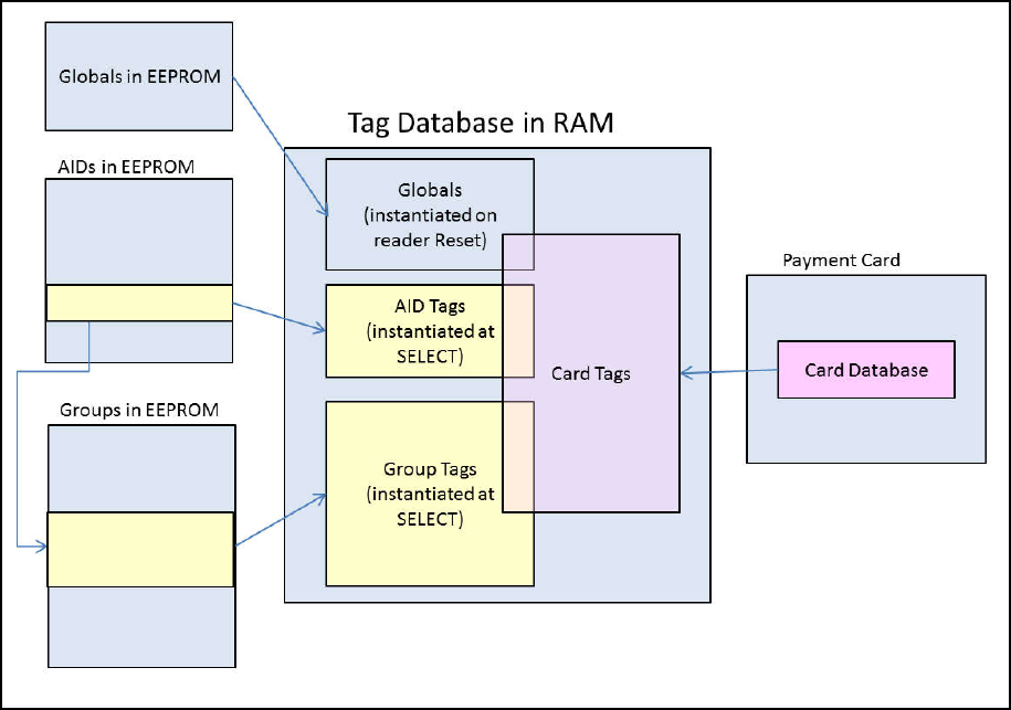
NEO Interface Developers Guide
45
5.0 Tag and Data Set Configuration
Tags are configured in the ViVOpay reader ahead of time so that when a card is
selected, a “data set” (group) may be instantiated for use in a transaction.
The following illustration shows the basic approach to instantiating the tag
database for a transaction. Global variables (configured through the Set
Configuration command) are instantiated when the reader is reset or powered
up. When a card is in the field, an AID is selected and its tags are added to the
database. The selection of the AID will cause a “data set” (group) to be
selected and its tags are added to the database. As the transaction proceeds,
card tags will be added to the database, possibly overwriting or updating some
tags that were already in the database.
The specification of MasterCard PayPass M/Chip 3.0 required some additional
features in the Tag Database, including:
The ability to have tags that were “not present” in the database.
The ability to handle 3-byte tags.
The specific details of changes for M/Chip 3.0 are covered in the following
sections.
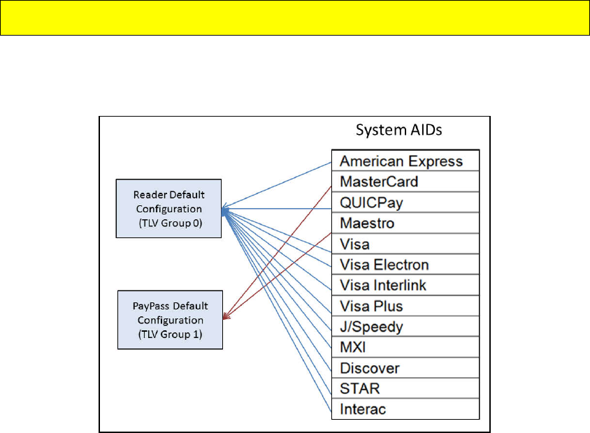
NEO Interface Developers Guide
46
Configurable AIDs and Groups
This section explains how you can create and modify Application Identifiers (AIDs) and associate
them with TLV Groups in the reader’s memory for specific transaction handling. Detailed
descriptions of the Configurable Application Identifier commands are also included.
Each AID uniquely identifies a payment application. The reader has default AIDs that are
preconfigured to support common payment applications such as VISA and MasterCard. These
AIDs are called the System AIDs and they can be modified or disabled but not deleted. The
reader also supports up to eight user-defined AIDs called User AIDs. Each AID must be associated
with a TLV Group that defines transaction processing for that payment application. The System
AIDs are initially associated with a default TLV Group, which can be modified but not deleted.
User AIDs can be associated to the default TLV Group or any of seven other user-defined TLV
Groups.
With the implementation of M/Chip 3.0, an additional default TLV Group (Group 1) has been
added. M/Chip 3.0 does not use the Reader Default Group (Group 0).
All AIDs must be unique. The reader’s default configuration is System AIDs and two default
groups. All of the System AIDs (except PayPass AIDs, as noted above) initially refer to the
default TLV Group 0. The diagram below shows the default reader AID configuration.
The Configurable Application Identifiers feature of the ViVOpay readers allows you to create and
customize AIDs and the TLV Groups associated with them. Each AID may have characteristics
that are unique and different from the reader’s default System AIDs and TLV Group
configuration.
To create a new configurable AID you need to send the AID and the TLV Group you wish to use to
the reader. If the AID already exists in the reader’s memory, it will modify the AID accordingly.
If you send a new AID, the reader creates and saves the new AID. Multiple AIDs can be
associated with the same TLV Group or they may refer to unique TLV Groups. You may also
redefine the functionality for an existing AID by linking it to a new configuration Group or you
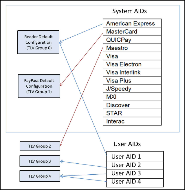
NEO Interface Developers Guide
47
may disable an AID if you do not want the reader to process transactions from that payment
application. You may delete an AID by communicating to the reader the AID number with no
parameters.
As you add or modify AIDs and TLV Groups, the reader remembers all changes on subsequent
boot up.
The diagram below shows an example of a reader’s AID configuration after it has been modified
with Configurable AID commands.
In this example, ten System AIDs have been disabled and four User AIDs and three new TLV
Groups have been configured. The new AID User AID – 1 has been linked to the Reader Default
Configuration (TLV Group 0) so that it functions as the other System AID 1 functions. The
Maestro AID has been linked to the user-defined TLV Group – 2. User AID – 2 functions as defined
in the new TLV Group – 3. Both User AID – 3 and User AID – 4 point to the new TLV Group – 4 and
function accordingly. Also notice that the other System AIDs have been disabled by removing
their link to a configuration group.
Use the Configurable AID Commands to create new AIDs or change configuration values for an
AID. Use the Configurable Group commands to create new groups or configuration values for a
group.

NEO Interface Developers Guide
48
System AIDs
A System AID is an AID preloaded for a specific application using a known AID value. Examples
include MasterCard, American Express, and Visa. The table below shows all the System AIDs.
Table 18: System AIDs
Application Name Application Identifier
American Express
A0 00 00 00 25 01
MasterCard
A0 00 00 00 04 10 10
QUICPay
A0 00 00 00 65 90 01
Maestro
A0 00 00 00 04 30 60
Visa
A0 00 00 00 03 10 10
Visa Electron
A0 00 00 00 03 20 10
Visa Interlink
A0 00 00 00 03 30 10
Visa Plus
A0 00 00 00 03 80 10
J/Speedy
A0 00 00 00 65 10 10
MXI
A0 00 00 00 02 30 60 D1 58 00
Discover
A0 00 00 03 24 10 10
Discover
A0 00 00 01 52 30 10
STAR
A0 00 00 04 17 01 01
Interac
A0 00 00 02 77 10 10
CUP Debit (Kiosk III only)
A0 00 00 03 33 01 01 01
CUP Credit(Kiosk III only)
A0 00 00 03 33 01 01 02
CUP Semi Credit(Kiosk III only)
A0 00 00 03 33 01 01 03
CUP Electronic Cash(Kiosk III only)
A0 00 00 03 33 01 01 06
SmartTap2.1
A0 00 00 04 76 D0 00
The terminal:
May disable a System AID
May ONLY modify some of the System AID properties
May NOT delete a System AID
User AIDs
A User AID is an optional AID that is added and/or configured by the user. These AIDs are used
for servicing transactions that are not defined by one of the System AIDs. This determination
needs to be made by the integrator.
The terminal:
May modify ANY User AID property
May delete a User AID
There is no equivalent to the System AID disable; the User AID either exists, and it is used for its
associated transactions, or the User AID is not present.

NEO Interface Developers Guide
49
Reader Default TLV Group
The reader is provided with a default TLV Group (Group 0) that defines all the properties (with
TLVs) required for a basic transaction. By default, all of the System AIDs except PayPass System
AIDs (MasterCard and Maestro) use TLV Group 0 to define their transaction processing. By
default, MasterCard PayPass System AIDs will use Group 1.
The user:
MUST ALWAYS include the Group Number TLV as the FIRST TLV in the Set Configurable
Group message.
MUST define AT LEAST ONE TLV in addition to the Group Number TLV (in a Set
Configurable Group command)
May modify ANY TLVs in TLV Group 0
May NEVER delete TLV Group 0
Unlike all other groups, the TLVs in the Default TLV Group (TLV Group 0) are constant. The
reader ALWAYS uses the latest copy of the TLV. If you issue a Set Configurable Group command
that only updates some TLVs in TLV Group 0, the reader continues to use older versions of the
TLVs that were not updated.
After each transaction, the reader reloads the default values from TLV Group 0, prior to the
next transaction. For this reason, TLV Group 0 maintains a copy of ALL TLVs that can be entered
into a TLV Group structure2.
Warning: Changing values in TLV Group 0 should be done with EXTREME CAUTION, since this
affects the default configuration that most (not PayPass) transactions use.
PayPass Default Group
The PayPass default group is Group 1. PayPass M/Chip 3.0 does not use Group 0
tag definitions (not even for default values). The process of instantiating a
PayPass database is slightly different from other applications:
Group 0 tags are not loaded.
28 default tags defined in the EMV Contactless Book C-2 Kernel 2 Spec
v2.3 are initialized with their specified default values. See PayPass Group
Configuration TLVs with Hard-Coded Values in Kernel.
PayPass Group tags are loaded. (Group 1 is the default group for PayPass
applications).
Tags sent in the Activate Command are loaded into the database.
User-defined TLV Groups
There are seven undefined TLV Groups in the reader at startup. These groups can be used for
any purpose.
2
PayPass specific tags are an exception to this rule. Those are maintained in Group 1.

NEO Interface Developers Guide
50
The user:
MUST ALWAYS include the Group Number TLV as the FIRST TLV in the message.
MUST include AT LEAST ONE TLV other than the Group Number TLV (in a Set
Configurable Group command)
May modify ANY TLV in the TLV Group
May ALWAYS delete a TLV Group 1 through 7
SHOULD NEVER include the TDOL TLV if its length = zero (i.e., only include the TDOL if
it has a value)
User-defined TLV Groups differ from the default TLV Group 0 in two important ways. First, these
groups only need to contain TLVs that are different than the TLVs in the default TLV Group 0.
Thus they are normally a sub-set of the TLVs in the default group.
For American Express Transaction limit(FFF1), CVM limit(FFF5), Floor limit(9F1B):
For Discover Transaction limit(FFF1), CVM limit(FFF5), Floor limit(9F1B), Risk flags(FFF4):
if user-defined TLV Group is used, user should set these above TLVs in the user-defined Group. If
not set, these above TLVs will be regard as not exist.
For American Express, Terminal Capabilities (9F33) and Enhanced Expresspay Terminal
Capabilities (9F6E) are expected to be set consistently. For example, if Byte 2 bit 7 of ‘9F6E’
is set to 1(b) to indicate ‘Online PIN Supported’ then ‘9F33’ byte 2 bit 7 should also be set to
1(b).
For American Express, Kiosk III reader is always capable of CVM processing, and CVM items in
terminal capabilities are supported (9F33 byte2 bit5-8 =1, 9F6E byte2 bit5-8 =1).
Secondly, the TLVs in TLV Groups 1 through 7 are not permanent. If you configure a TLV Group
and then issue a second Set Configurable Group command on the same TLV Group, the second
Set Configurable Group command overwrites EVERY change to the TLV Group made by the first
command.
Warning: Changing values in TLV Groups 1 through 7 overwrites all content in the TLV Group,
including deleting TLVs not in the update.
Except for MasterCard PayPass transactions, when one of these user-defined TLV Groups is
selected during a transaction, the reader uses the TLVs included in the group AND any other
TLVs required for the transaction are taken from the default Group 0. Once the reader has
finished transaction processing, it reloads TLV Group 0 values for all TLVs. It is now ready to
commence the next transaction.
There are some guidelines for setting and deleting TLV Groups listed below. Most of these
guidelines are intuitive (i.e., you may not delete a TLV Group if an AID exists that currently uses
it).
Configurable AID Reader Memory Requirement
The Configurable AIDs feature requires memory to store TLV groups and User AIDs. ViVOpay
readers use 64K flash memory to support the Configurable AID feature. Refer to the reader’s
user documentation for more information on reader memory.
NEO Interface Developers Guide
51
ViVOpay Proprietary TLVs
TLVs may be either standard TLVs or proprietary TLVs. Standard TLVs are defined by EMV and
the Payment Association Requirements and recognized by everyone. Proprietary TLVs are
created by individual payment associations and reader manufacturers for specific functions.
Proprietary TLVs must be handled in a manner that isolates them from other proprietary TLVs.
ViVOpay proprietary TLVs can be present with standard TLVs without encapsulation when the
command is processed exclusively by ViVOpay firmware or software. If the TLVs will be
processed by other devices, ViVOpay proprietary TLVs must be encapsulated to prevent conflicts
with proprietary TLVs from other organizations.
ViVOPay TLV Group Tag FFEE01 is used to encapsulate ViVOpay proprietary TLVs.
EXAMPLE
The following example is for an encapsulated Terminal Capabilities – CVM Required TLV.
The TLV string “FFEE0106DF29030101” is broken down as follows:
FFEE01 ViVOpay TLV Group Tag
06 Length of all encapsulated TLVs
DF29 Tag Terminal Capabilities – CVM Required – ViVOpay Proprietary
03 Length of Transaction CVM
00 01 00 Value: Actual Transaction CVM
Card Application Proprietary Tag List (FF69)
For some applications, there may be a requirement to define a list of
proprietary tags that may be returned in Data Object Lists (DOLs). To
accomplish this, the reader allows each user-defined group (except Group 0) to
define a list of proprietary tags that can be inserted into the tag database. The
maximum size of this list is 32 bytes. The new tag that is used for encapsulating
the proprietary tag list is FF69.
A tag in this list may be configured in one of two ways:
Constant Value – the TLV contains a non-zero length and a value. The
reader will not modify this value, but it can be provided when requested
(as in a DOL).
Updateable – the TLV contains a length of zero and no value. The tag is
then “defined” but has no value, so it may be updated during the

NEO Interface Developers Guide
52
transaction. At the end of a transaction, the reader will send any
updated proprietary tags back in the Activate Response frame.
Configuration Tag Tables
Global Configuration Tags
The following table contains TLVs that are configurable using the Set
Configuration (04-00) command. These TLVs are global within in the reader.
Table 19: Global Configuration TLVs
Tag Data Object Name and Description Format
Length
(Bytes)
Default Value
9A
Transaction Date (YYMMDD)
This value is used to set the Real Time Clock.
Note: The terminal/POS application should perform
range checking on this value to ensure it is within
acceptable limits.
n6 3 Reader Date
9F21
Transaction Time (HHMMSS)
This value is used to set the Real Time Clock.
Note: The terminal/POS application should perform
range checking on this value to ensure it is within
acceptable limits.
n6 3 Reader Time
DF65[1]
Require Heartbeat frame to stay in Idle mode (EMEA
User Experience only). If this feature is enabled, then
to stay in the Idle mode, a valid frame must be
received by the reader every 15 seconds or it returns
to Not Working state.
00: Heartbeat frame not required
01: Heartbeat frame required
b 1 00
DF66[1]
Unsupported cards display option (EMEA User
Experience only). If an unsupported card is detected,
then display a message based on this setting.
00: Display a “Fail” message
01: Display an “Insert/ Swipe” message if the reader
is configured to indicate support for Contact cards,
otherwise display a “Fail” message.
b 1 00
DF68
Enable/Disable Stop Command processing
0 = Disable (default)
1 = Enable
b 1 00
DF6A
Enable Communication Error Recovery
Enables the reader to poll again and return to
discovery after a communication error (e.g. tear or
“no tag” error)
00: Disabled
01: Enabled (default)
b 1 01

NEO Interface Developers Guide
53
Tag Data Object Name and Description Format
Length
(Bytes)
Default Value
DF75
Communication Error Delay time
Delay between the time a communication error first
occurs and the time when the reader will issue an
indication of an error to the reader. If a tear
occurs, but the card comes back into the field during
this time, then no error indication is issued. Time is
expressed in milliseconds (default is 3000ms, or 3
seconds)
n
(BCD)
3 00 30 00
DF7C
Auto-Switch to Pass-Through Mode.
Refer to Auto-Switch to Pass-Through Mode
00: Disable (default)
01: Enable
b 1 00
DF7D
Track 1 and Track 2 Data Format
Sets the format of data returned from Activate
Transaction and Get Transaction Results commands.
00: No start/end sentinels or LRC (default)
01: Add start/end sentinel and LRC
b 1 00
DF7F
Improved Collision Detection (see special features
Improved Collision Detection.) RF signal locked to a
specified card only after a specified number of
polling attempts without an EMV collision.
00h = Improved Collision Detection Disabled.
02h-FFh = Number of successful polling attempts
required.
b 1 00
FFF3[1]
Application Capability(1:Support,0:Not Support):
Byte 1: (Leftmost)
b8
b7
b6
b5
b4
b3
b2
b1
Meaning (0 = disable, 1 =
enable)
X
Normal J/Speedy support
X
ViVOpay Mifare for NFC
X
Interac support
X
CUP support
X
SmartTap support
X
X
X
RFU
Byte 2:
b8
b7
b6
b5
b4
b3
b2
b1
Meaning (0 = disable, 1 =
enable)
-
-
-
-
-
-
-
X
MasterCard Credit support
-
-
-
-
-
-
X
-
American Express support
-
-
-
-
-
X
-
-
Visa support
-
-
-
-
X
-
-
-
Mobile J/Speedy support
-
-
-
X
-
-
-
-
ViVOwallet support
-
-
X
-
-
-
-
-
RBS support
-
X
-
-
-
-
-
-
MasterCard Cash support
X
-
-
-
-
-
-
-
Discover support
Example: 0009 means reader support both
MasterCard and Mobile J/Speedy applications
b 2
07 FF
(0F FF for Kiosk
III)

NEO Interface Developers Guide
54
Tag Data Object Name and Description Format
Length
(Bytes)
Default Value
FFF7[1]
Enable/Disable Burst Mode:
Value = 00: Disable Burst Mode
Value = 01: Enable Burst Mode
Value = 02: Burst Mode Auto Exit. Burst mode is
turned off as soon as a transaction command is
received (Sections 6 and 14 of this document)
b 1 02
FFF9[1]
[2] [3]
LCD Font Size:
Value = 02: Large
Value = 03: Extra Large (default)
b 1 03
FFFA[1]
[2]
LCD delay time (ms) – default is 1000ms.
If the device has no LCD, then the value will be 0. b 2
03 E8
or
00 00
FFFB[1]
Language Option for LCD display:
Value = 00: English only display (default)
Value = 01: Chinese only display[2]
Value = 02: English & Chinese display[2]
Value = 03: French only display
Value = 04: Other Language (if ILM present)[2]
Value = 05: English & French display
[4]
b 1 00
DF891B
Poll Mode
Value = 00 : Auto-Poll
Value = 01 : Poll on Demand
Note: Only used for Vendi.
b 1 00
9F15
Merchant Category Code
Classifies the type of business being done by the
merchant, see ISO 8583:1993.
n4
2
00 00
9F16
Merchant Identifier
ans
15
00 00 00 00 00
00 00 00 00 00
00 00 00 00 00
9F1C
Terminal Identification
an
8
00 00 00 00 00
00 00 00
9F40
Additional Terminal Capabilities
Indicates the data input and output capabilities of
the terminal.
b
5
60 00 00 10 01
9F4E
Merchant Name and Location
Allows the reader to be configured with the
Merchants Name and Location (VCPS 2.1.1 and
M/Chip 3.0)
ASCII
<=30
00 00 00 00 00
00 00 00 00 00
00 00 00 00 00
00 00 00 00 00
00 00 00 00 00
00 00 00 00 00
9F7C
Merchant Custom Data
b
<=20
00 00 00 00 00
00 00 00 00 00
00 00 00 00 00
00 00 00 00 00
FFF2
Interface Device Serial Number
This is equivalent to tag 9F1E. They refer to the same
parameter.
an
8
30 30 30 30 30
30 30 30

NEO Interface Developers Guide
55
Tag Data Object Name and Description Format
Length
(Bytes)
Default Value
FFF8
UI Scheme:
Value = 00:ViVOpay User Interface (default)
Value = 02:Visa Wave User Interface
Value = 03:EMEA User Interface
Note: LCD Messages need to be configured
separately.
Warning: EMEA UI is intended for use in the EMV or
European environment, where the reader Vend is not
allowed to poll continuously (e.g., operate in Auto
Poll Mode). The reader Vend does NOT support Auto
Poll while in EMEA UI mode. The reader is not
certified to work properly in this situation.
The reader Vendi supports Auto Poll while in EMEA UI
mode.
b
1
00
9F53
Transaction Category Code
Indicate type of transaction being performed,
defined by MasterCard and Interac.
an
1
00
DFEF36
MTAS(Media Tracking And Status)
Byte 1: (Leftmost)
b8
b7
b6
b5
b4
b3
b2
b1
Meaning (0 = disable, 1 =
enable)
X
CL Media Arrival Reproting
X
CL Media Removal Reproting
X
X
X
X
X
X
RFU
Byte 2:
b8
b7
b6
b5
b4
b3
b2
b1
Notes
-
-
-
-
-
-
-
X
0 - RF Antenna Off
1 - RF Antenna On
-
-
-
-
-
-
X
-
0 - RF Field Deactiated
1 - RF Field Activated
-
-
-
-
-
X
-
-
0 - No event
1 - RF Field Activated
-
-
-
-
X
-
-
-
0 - No event
1 - CL Midia Arrival Detected
-
-
-
X
-
-
-
-
0 - No event
1 - CL Media Removal
Detected.
-X
X-
X
-
-
-
-
-
RFU
Byte 3: RFU
Byte 2: RFU
b 4 00 00 00 00
FFEE1C UN range
b
4
Not present
FFEE1D Masked Output Data Parameter
b 5 04 04 2A 0C 31
NEO Interface Developers Guide
56
Tag Data Object Name and Description Format
Length
(Bytes)
Default Value
FFEE1E
Group 0 Initialize Flag:
Value = 00: not initialized.(If the tag is not found or
Value is not 1, reader will initialize group 0 with
default setting automatically when the power cycle
is on)
Value = 01: Initialized
b 1 01
[1]
These objects use proprietary tags. The use of these tags should be restricted to the serial interface. Once the
Reader has returned an OK Response Frame, the Terminal application should dispose of the tags to avoid conflicts with
other proprietary TLVs.
[2]
These objects only work on the ViVOpay graphic reader.
[3]
Only applies to non-index messages. The default size for the LCD Font is 3. The Lookup table for all the messages are
hard coded with the Font Size 3. The Font Size = 2 is treated only when the three messages are displayed on the screen.
When the user wants to use the LCD Font size = 2, A store LCD message command can be used to configure the string by
prefixing the %F2.
[4]
These objects only work on the Vendi.
Group Configuration Tags
The following table contains tags that may be configured within a Configurable
Group. For Group 0, default values exist. Except for groups associated with a
PayPass AID, if a group does not define some of these TLVs, then the values in
Group 0 will be used. The Set Configurable Group command should be used to
set the TLVs in this section.
The PayPass configuration tags are documented separately. To configure a group that will be
associated with a PayPass AID, refer to PayPass Group Configuration TLVs.
Table 20: Group Configuration TLVs
Tag Description Format
Length
Default Value in
Group 0
9F58
Merchant Type Indicator
Provides Merchant Type Indicator used by the card for
risk management. Five values are valid: 01, 02, 03, 04
and 05. (Interac)
n1 1 03
9F59
Terminal Transaction Information (TTI)
Provides Terminal Transaction Information for the
current transaction. (Interac)
Note: Vendi default values are B4 07 00.
b 3 DC 80 00
9F5D
Terminal Contactless Receipt Required Limit
Limit Amount used to compare against Transaction
amount to automatically print a transaction record.
(Interac)
n12 6 00 00 00 00 50 00
Only used for Kiosk III.

NEO Interface Developers Guide
57
Tag Description Format
Length
Default Value in
Group 0
9F5E
Terminal Option Status
Options supported by the terminal. (Interac)
Note: Vendi default values are 00 00.
b 2 E0 00
9F5F
Terminal (Reader) Contactless Floor Limit
Floor limit amount used to compare against
Transaction amount. (Interac)
n12 6 00 00 00 00 80 00
DF26
Enable/Disable Certificate Revocation list
0 = disable
1 = enable (default)
M/Chip 3.02 can make use of the Certificate
Revocation list.
Note: Vendi default value is not present.
b 1 01
DF2A
Threshold Value for Biased Random Selection
Value used in terminal risk management for random
transaction selection. (Interac)
n12 6 00 00 00 00 50 00
DF2B
Maximum Target Percentage for Biased Random
Selection
Value used in terminal risk management for random
transaction selection. (Interac)
b
1 32
DF2C
Target Percentage for Random Selection
Value used in terminal risk management for random
transaction selection. (Interac)
b 1 0A
DF51[1]
ExpressPay Terminal Capabilities
Used to create the ExpressPay Terminal Capabilities
TLV, 9F6D for Amex ExpressPay applications.
Note: Vendi default value is not present.
b 1 80
DF64[1]
Enable/Disable Visa Wave cards
Enables the use of Visa Wave cards (not the Visa Wave
protocol).
00: Reject Visa Wave cards
01: Accept Visa Wave cards
b 1 00
97
Default Transaction Certificate Data Object List (TDOL)
List of TLV data objects to be used by the terminal to
generate the TC Hash Value in case the TDOL is not
returned by the card.
Note: Vendi default value is not present.
In Group 0, this tag must be encapsulated in
another tag, FF67. FF67 encapsulates all “variable
length” tags in group 0.
b <=64 Zero length
9C
Transaction Type
Indicates the type of financial transaction, represented
by the first two digits of ISO 8583:1987 Processing
Code. (default = purchase goods or services)
n2 1 00
NEO Interface Developers Guide
58
Tag Description Format
Length
Default Value in
Group 0
5F2A
Transaction Currency Code
Indicates the currency code of the transaction
according to ISO 4217. Note: make sure you use the
same Transaction Currency Code for all configurable
AIDs. (default = US Dollars)
n3 2 08 40
5F36
Transaction Currency Exponent
Indicates the implied position of the decimal point
from the right of the transaction amount represented
according to ISO 4217. (decimal is two places from
right of the transaction amount)
n1 1 02
9F01
Acquirer ID
n
6
Not present
9F02
Amount Authorized (Numeric)
n12
6
00 00 00 00 00 01
9F03
Amount Other (Numeric)
n12
6
00 00 00 00 00 00
9F09
Application Version Number
PayPass M/Chip (Value = 00 02)
D-PAS (Value = 00 02)
Interac (Value = 00 02)
Amex (Value = 00 01)
b 2 00 02
9F1A
Terminal Country Code
Indicates the country code of the terminal,
represented according to ISO 3166. Default = US
n3 2 08 40
9F1B
Terminal Floor Limit
Indicates the floor limit in the terminal for the AID(s)
associated with this group.
Note: The value is the decimal limit amount given
in binary represented in Hex in the
command/response. (100 limit = 10000 decimal =
2710h).
Default = $60.00
b 4 00 00 17 70
9F1C
Terminal Identification
Note: Vendi default value is not present.
an 8 00 00 00 00 00 00
00 00
9F33
Terminal Capabilities
Indicates the card data input, CVM, and security
capabilities of the terminal
Default =
No CVM required
SDA supported
DDA supported
Card Capture
CDA supported
b 3 00 08 E8
9F35
Terminal Type
Indicates the environment of the terminal, its
communications capability, and its operational control
Note: Vendi default value is 25.
n2 1 22
9F66
Terminal Transaction Qualifier (TTQ)
Determine the type of transaction (MSD, qVSDC, and
Contactless VSDC) and whether online processing is
supported.
b 4
80 00 40 00
(27 00 40 80 for
CUP)
NEO Interface Developers Guide
59
Tag Description Format
Length
Default Value in
Group 0
9F6D
Application Version Number (MagStripe)
PayPass MagStripe (Value = 00 01)
Note: Vendi default value is not present.
b 2 00 01
DF28
Terminal Capabilities – No CVM Required
M/Chip v2.0 element indicating the Terminal
Capabilities to be used when Amount, Authorized <
CVM Required Limit. Formatted as Terminal
Capabilities (tag ‘9F 33’)
Only byte 2 of this tag is actually used. The other
terminal capabilities are configured using tag 9F33.
Note: Vendi default value is not present.
DF28 Byte
PayPass Tag Equivalent
2
DF8119
b 3 00 08 E8
DF29
Terminal Capabilities – CVM Required
M/Chip v2.0 element indicating the Terminal
Capabilities to be used when Amount, Authorized >=
CVM Required Limit. Formatted as Terminal
Capabilities (tag ‘9F 33’)
Only byte 2 of this tag is actually used. The other
terminal capabilities are configured using tag 9F33.
Note: Vendi default value is not present.
DF29 Byte
PayPass Tag Equivalent
2
DF8118
b 3 00 68 E8
FFE4[1]
Group Number
The group number assigned to this group of
parameters. AIDs may be associated with the group
number.
This tag is mandatory when getting or setting group
parameters and it must be the 1st TLV in Data Field.
It is used as the “key” for the group parameter set.
n2 1 --
FFF1[1]
Terminal Contactless Transaction Limit
Indicates the terminal limit for this AID for Contactless
transactions.
n12 6 00 00 00 01 00 00
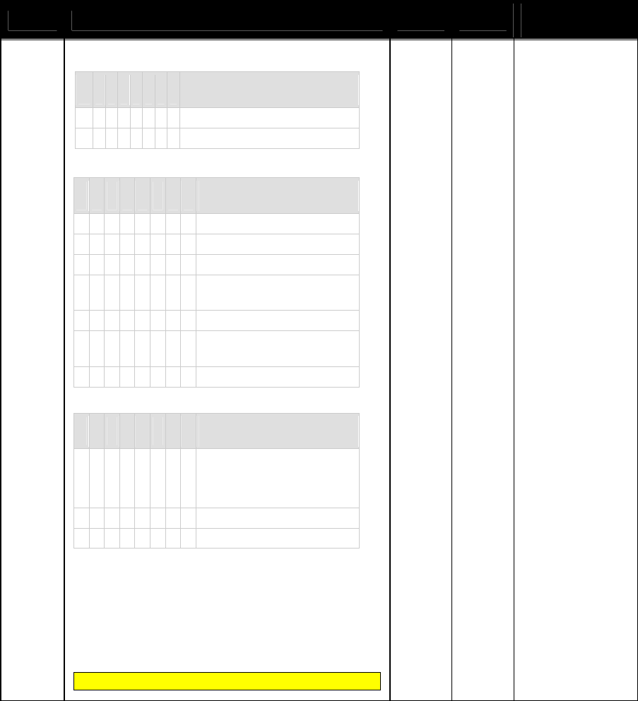
NEO Interface Developers Guide
60
Tag Description Format
Length
Default Value in
Group 0
FFF4[1]
Visa Reader Risk Flags
Byte 1
b
8
b
7
b
6
b
5
b
4
b
3
b
2
b
1
Meaning
(0 = disable, 1 = enable)
-
-
-
-
-
-
-
X
Status Check
X
X
X
X
X
X
X
-
RFU
Byte 2:
b
8
b
7
b
6
b
5
b
4
b
3
b
2
b
1
Meaning
(0 = disable, 1 = enable)
-
-
-
-
-
-
-
X
Transaction Limit Check
-
-
-
-
-
-
X
-
CVM Required Limit Test
-
-
-
-
-
X
-
-
Terminal Floor Limit Check
-
-
-
-
X
-
-
-
Cash Transaction Reader Risk
(RR)
-
-
-
X
-
-
-
-
Cashback Reader Risk (RR)
-
-
X
-
-
-
-
-
DRL (Dynamic Reader Limits)
RR
X
X
-
-
-
-
-
-
RFU
Byte 3
b
8
b
7
b
6
b
5
b
4
b
3
b
2
b
1
Meaning
(0 = disable, 1 = enable)
-
-
-
-
-
-
-
X
1 = online cryptogram required
for zero amount (only used
with zero amount check
enabled)
-
-
-
-
-
-
X
-
1 = perform zero amount check
X
X
X
X
X
X
-
-
RFU
For example:
0x00 = Zero Amount check disabled.
0x01 = Zero Amount check is disabled and online
cryptogram required bit will not be checked.
(default)
0x02 = Zero Amount check enabled.
0x03 = Zero Amount check enabled and Option 1,
online Cryptogram Required
Note: Vendi default values are 01 00 01.
b 3 00 06 01

NEO Interface Developers Guide
61
Tag Description Format
Length
Default Value in
Group 0
D-PAS Reader Risk Flags:
Byte 1
b
8
b
7
b
6
b
5
b
4
b
3
b
2
b
1
Meaning
(0 = disable, 1 = enable)
-
-
-
-
-
-
-
X
RFU
X
1=Status Check Support
X
X
X
X
X
X
-
RFU
Byte 2:
b
8
b
7
b
6
b
5
b
4
b
3
b
2
b
1
Meaning
(0 = disable, 1 = enable)
X
X
X
X
X
X
X
X
RFU
Byte 3
b
8
b
7
b
6
b
5
b
4
b
3
b
2
b
1
Meaning
(0 = disable, 1 = enable)
-
-
-
-
-
-
-
X
1 = online cryptogram required for
zero amount
X
X
X
X
X
X
X
-
RFU
b 3
FFF5[1]
CVM Required Limit
Indicates the CVM required limit in the terminal for the
associated AIDs.
n12 6 00 00 00 00 80 00
FFFC[1]
PayPass Profile (also used for Amex)
Information in this tag is equivalent to PayPass tag
DF811B, although it is formatted slightly differently:
87654321
Bit Meaning Value
-------X
MagStripe Only
0 = normal transaction
1 = MagStripe only
transaction allowed
------X-
M/Chip Only
0 = normal transaction
1 = M/Chip only
transaction allowed
-----X--
On Device CVM 0 = not supported
1 = supported
XXXXX---
RFU
The default value is 0x01 – support MagStripe only.
Note: Vendi default value is not present.
b 1 01
FFFD[1]
Terminal Action Code (Online)
Reflect the acquirer-selected action to be taken upon
analysis of the TVR.
b 5 F8 50 AC F8 00
FFFE[1]
Terminal Action Code (Default)
Reflect the acquirer-selected action to be taken upon
analysis of the TVR.
b 5 F8 50 AC A0 00
FFFF[1]
Terminal Action Code (Denial)
Reflect the acquirer-selected action to be taken upon
analysis of the TVR.
b 5 00 00 00 00 00
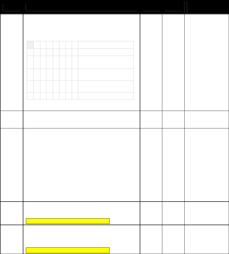
NEO Interface Developers Guide
62
Tag Description Format
Length
Default Value in
Group 0
FFF0[1]
Specific Feature Switch
Used with Visa VCPS 2.1.1/2.1.2. It controls Visa CVN17
support and Track 1 & 2 data in the transaction
response.
Byte 1
b8
b7
b6
b5
b4
b3
b2
b1
-
-
-
-
-
-
-
X
RFU (Deprecated)
-
-
-
-
-
-
X
-
1 = Visa CVN17 supported
0 = Visa CVN17 disabled
-
-
-
-
-
X
-
-
1 = Remove Track 1 data in
Visa response
-
-
-
-
X
-
-
-
1 = Remove Track 2 data in
Visa response
X
X
X
X
-
-
-
-
RFU
Byte 2: RFU
Byte 3: RFU
b 3 02 00 00
9F5A
Terminal Transaction Type (Interac)
• 0x00 = Purchase
• 0x01 = Refund
b
1
00
FFEE1D
Masked Output Data Parameter
When there is a PAN to be output in masked format,
this parameter gives the key points of the format.
Byte 1: PrePAN, value scope is [0, 6],
Byte 2: PosPAN, value scope is [0, 4],
Byte 3: MaskAscii, value scope is [20h, 7Eh],
Byte 4: MaskHex, value scope is [0Ah, 0Fh]
Byte 5: Expire date output option,
0x30=Mask, 0x31=NotMask, default 0x31
For detailed rules, please refer to "ID-Tech Encypt Data
Format In Command / Response Specification for ICC
Communication".
b 5 04 04 2A 0C 31
9F41
Counter maintained by the terminal that is
incremented by one for each transaction
Note: Vendi default value is not present.
n 4 4 Not Present
DF891C
“Interac Retry Limit”
Configured value for the total number of tap
attempts during an Interac Mobile Debit (NFC) application
transaction.
Note: Vendi default value is not present.
n1 1 Not Present

NEO Interface Developers Guide
63
Tag Description Format
Length
Default Value in
Group 0
DFEF2F
CUP Risk and Configuration Flag
Byte 1
b8
b7
b6
b5
b4
b3
b2
b1
-
-
-
-
-
-
-
X
Status Check
-
-
-
-
-
-
X
-
Transaction Limit Check
-
-
-
-
-
X
-
-
CVM required Limit Check
-
-
-
-
X
-
-
-
Terminal Floor Limit Check
-
-
-
X
-
-
-
-
Zero Amount Check
X
X
X
-
-
-
-
-
RFU
Byte 2:
b8
b7
b6
b5
b4
b3
b2
b1
-
-
-
-
-
-
-
X
RFU
-
-
-
-
-
-
X
-
Exception File Support
-
-
-
-
X
X
-
-
RFU
-
-
-
X
-
-
-
-
Online Authentication
Support
-
-
X
-
-
-
-
-
RFU
-
X
-
-
-
-
-
-
UPI Support
X
-
-
-
-
-
-
-
Cardholder Credential
Support
Byte 3:
b8
b7
b6
b5
b4
b3
b2
b1
-
-
-
-
-
-
-
X
Encrypt Keyboard Support
-
-
-
-
-
-
X
-
Reversal Support
-
-
-
-
-
X
-
-
qUICS Online ODA Fail
Decision:
1 = Go Online
0 = Decline
X
X
X
X
X
-
-
-
RFU
Byte 4: RFU
b 4 Not Present
DFEE3F
Default TDOL b var Not Present
[1]
These objects use proprietary tags. The use of these tags should be restricted to the serial interface. Once the
Reader has returned an OK Response Frame, the Terminal application should dispose of the tags to avoid conflicts with
other proprietary TLVs.
[2]
Not used by M/Chip 3.0 because M/Chip 3.0 redefines this as a card tag that passes Application Capability Information.
[3]
These objects only work on the Vendi.
[4]
These objects only work on the ViVOpay graphic reader.
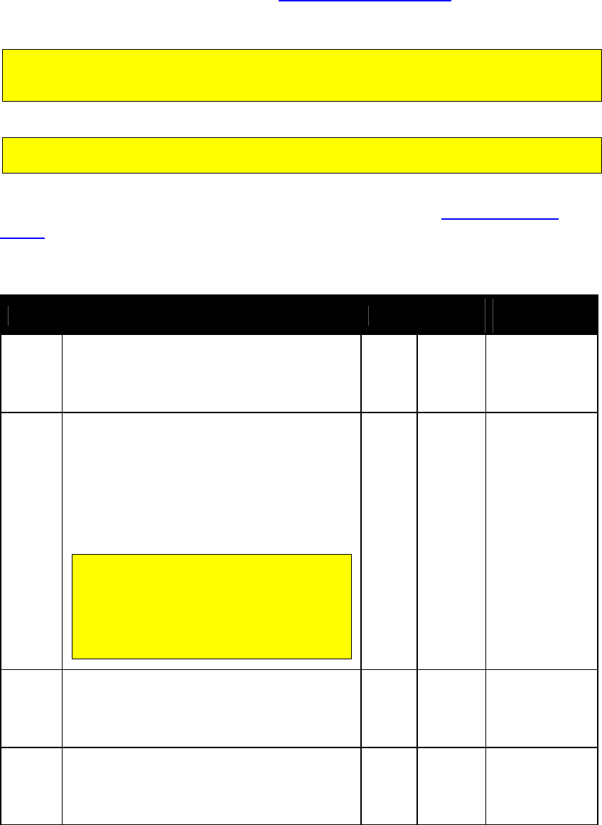
NEO Interface Developers Guide
64
PayPass Group Configuration TLVs
If a PayPass AID will be assigned to a group, then the table in this section should
be used to configure the group. The Set Configurable Group command should
be used to set the TLVs in this section.
The following PayPass Group TLVs should not be configured for Group 0. The default PayPass
group is Group 1. That is, when the reader is configured from the factory, the PayPass
System AIDs will be associated with Group 1.
If there are tags in a PayPass group that should be set, they must all be set explicitly, since
the absent values are not filled in with Group 0 or Group 1 defaults.
PayPass Group tags are instantiated a little differently than other groups.
Group 0 is never used as a default. Refer to the section on PayPass Default
Group for an explanation of how the tag database is instantiated for PayPass.
Table 21: PayPass Default Group Configuration TLVs
Tag Description Format
Length Default Value in
Group 1
97
Default Transaction Certificate Data Object List
(TDOL)
List of TLV data objects to be used by the
terminal to generate the TC Hash Value in case
the TDOL is not returned by the card
b <=64 Not present
9A
Transaction Date (YYMMDD)
Indicates local date that the transaction was
authorized.
Note: The reader does not perform range checking
on this value. The POS application should perform
range checking on this value to ensure it is within
acceptable limits.
Default value = FF FF FF (use the RTC for date and
time.)
When this value is set in a PayPass group, it
should generally be set to FF FF FF (use the
RTC). Setting this value to something other
than FF FF FF may have unexpected results.
The transaction date and time may be
overridden by the terminal if the 9A and 9F21
TLVS are supplied in an Activate command.
n6 3 FF FF FF
9C
Transaction Type
Indicates the type of financial transaction,
represented by the first two digits of ISO
8583:1987 Processing Code (default = purchase
goods or services)
n2 1 00
5F2A
Transaction Currency Code
Indicates the currency code of the transaction
according to ISO 4217. Note: make sure you use
the same Transaction Currency Code for all
configurable AIDs. Default = US Dollars(08 40)
n3 2 08 40
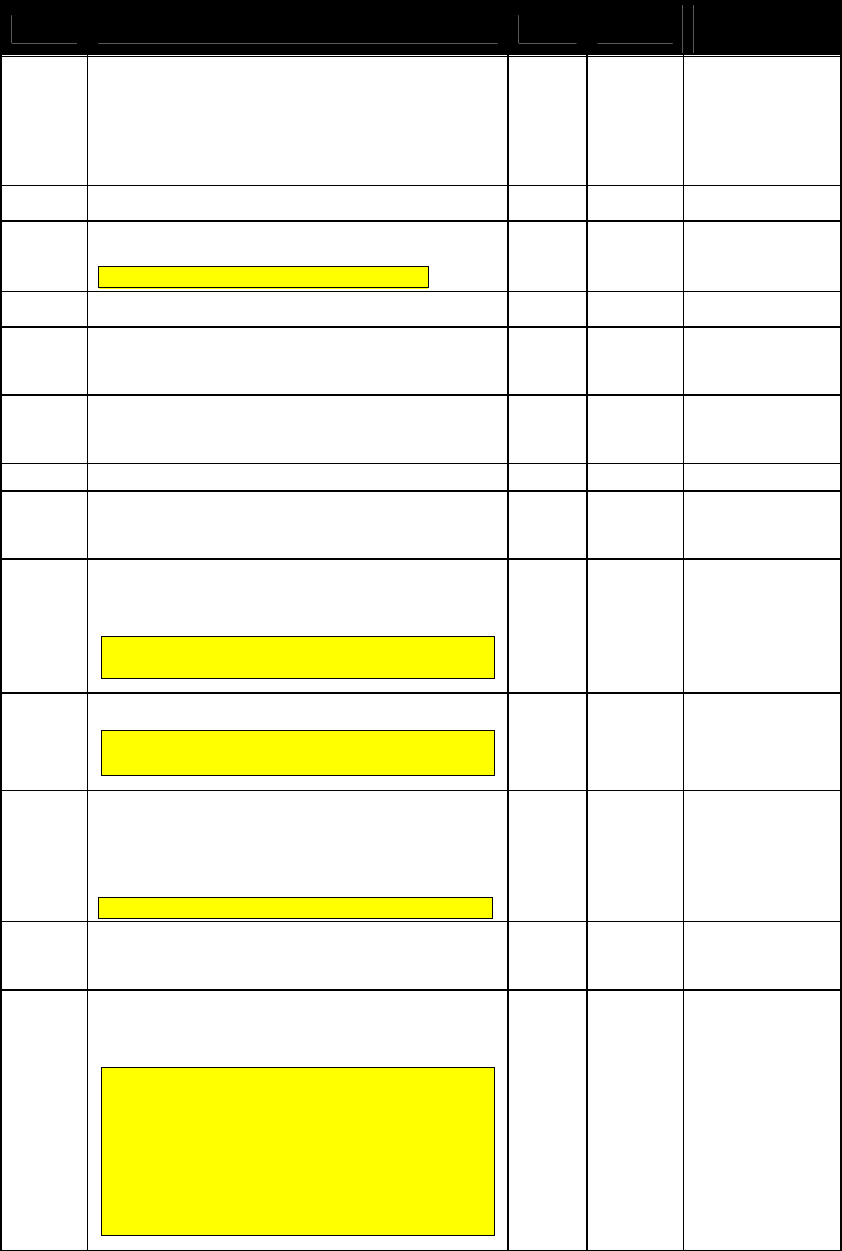
NEO Interface Developers Guide
65
Tag Description Format
Length Default Value in
Group 1
5F36
Transaction Currency Exponent
Indicates the implied position of the decimal point
from the right of the transaction amount
represented according to ISO 4217.
Default = decimal is two places to the right of the
last digit of the transaction amount.
n1 1 02
9F01 Acquirer ID n 6 Not present
9F02
Amount Authorized (Numeric)
Note: Vendi default value is not present.
n12 6 00 00 00 00 00 01
9F03 Amount Other (Numeric) n12 6 00 00 00 00 00 00
9F09
Application Version Number (M/Chip)
PayPass M/Chip 3.0(Value = 00 02)
Amex (Value = 00 01)
b 2 00 02
9F15
Merchant Category Code
Classifies the type of business being done by the
merchant, see ISO 8583:1993.
n4 2 11 11
9F16
Merchant Identifier
ans
15
Not present
9F1A
Terminal Country Code
Indicates the country code of the terminal,
represented according to ISO 3166.
n3 2 08 40
9F1B
Terminal Floor Limit
Indicates the floor limit in the terminal in
conjunction with the AID (hex).
This tag is equivalent to MasterCard tag DF8123
Reader Contactless Floor Limit.
b 4 00 00 17 70
9F1C
Terminal Identification
Note: Vendi default values are 00 00 00 00 00
00 00 00.
an 8 zero length
9F1E
Interface Device Serial Number
This is intended to be the serial number of the
terminal/POS. It is configured by the POS and is
unique to the terminal.
Note: KioskIII/Vendi default value is not present.
an 8 30 30 30 30 30 30
30 30
9F21
Transaction Time (HHMMSS)
Indicates local time that the transaction was
authorized. Default = use RTC.
n6 3 FF FF FF
9F33
Terminal Capabilities
Indicates the card data input, CVM, and security
capabilities of the terminal.
This tag (9F33) only configures bytes 1 and 3 of the
terminal capabilities. Byte 2 of the terminal
capabilities actually comes from DF28 or DF29
during the transaction. Refer to tags DF28 and DF29
for details.
Note: Byte 1 of 9F33 is the same as DF8117 Card
Data Inpput Capability defined in PayPass 3.0.2 and
Byte 3 of 9F33 is the same as DF811F Security
Capability.
b 3 00 08 E8
NEO Interface Developers Guide
66
Tag Description Format
Length Default Value in
Group 1
9F35
Terminal Type
Indicates the environment of the terminal, its
communications capability, and its operational
control
Note: Vendi default value is 25.
n2 1 22
9F40
Additional Terminal Capabilities
Indicates the data input and output capabilities of
the terminal
Note: Vendi default values are 60 00 00 10 01.
b 5 60 00 00 30 00
9F4E
Merchant Name and Location
Allows the reader to be configured with the
Merchants Name and Location (VCPS 2.1.1 and
M/Chip 3.0)
ASCII 30 Not present
9F53
Transaction Category Code
This is a data object defined by MasterCard which
indicates the type of transaction being performed,
and which may be used in card risk management.
Note: Vendi default value is 00.
an 1 01
9F66
Terminal Transaction Qualifier (TTQ)
Determine the type of transaction (MSD, qVSDC,
and Contactless VSDC) and whether online
processing is supported.
b 4 Not present
9F6D
Application Version Number (MagStripe)
PayPass MagStripe (Value = 00 01)
b 2 00 01
9F6E
Third Party Data
Not present
9F7C Merchant Custom Data b <=20
00 00 00 00 00 00
00 00 00 00 00 00
00 00 00 00 00 00
00 00
9F7E
Mobile Support Indication. (PayPass only)
Note: Vendi default value is 00. b 1 Zero length
DF28
Terminal Capabilities – No CVM Required
M/Chip v2.0 element indicating the Terminal
Capabilities to be used when Amount, Authorized
< CVM Required Limit. Formatted as Terminal
Capabilities (tag ‘9F 33’)
Only byte 2 of this tag is actually used. The other
terminal capabilities are configured using tag 9F33.
DF28 Byte
PayPass Tag Equivalent
2
DF8119
b 3 00 08 E8

NEO Interface Developers Guide
67
Tag Description Format
Length Default Value in
Group 1
DF29
Terminal Capabilities – CVM Required
M/Chip v2.0 element indicating the Terminal
Capabilities to be used when Amount,
Authorized >= CVM Required Limit. Formatted as
Terminal Capabilities (tag ‘9F 33’)
Only byte 2 of this tag is actually used. The other
terminal capabilities are configured using tag 9F33.
DF29 Byte
PayPass Tag Equivalent
2
DF8118
b 3 00 68 E8
DF8104
Pre Gen-AC Balance Read
If this tag is defined, a transaction will read the
balance before Gen-AC. This tag may also be sent
in the Activate to indicate that the balance should
be read prior to Gen-AC.
n12 6 Not present
DF8105
Post Gen-AC Balance Read
If this tag is defined, a transaction will read the
balance after Gen-AC. This tag may also be sent
in the Activate to indicate that the balance should
be read after Gen-AC.
n12 6 Not present
DF811A
Default UDOL
Used for calculating the CCC if no UDOL is present
in the card. The default is the tag and length of
the “Unpredictable Number”.
b 3 9F 6A 04
DF811C
Maximum Lifetime of Torn Transaction Record
This is the maximum time a torn record can exist
in the log before it expires. It is expressed in
seconds.
While the transaction log is global to the reader,
the MasterCard application is the only application
that supports it.
b 2 Not Present
DF811D
Maximum Number of Torn Transaction Records
Due to storage limitations, the maximum number
of records that may be configured is 2. There
may be 0, 1, or 2 torn transaction records
configured. If 0 records are configured, the torn
transaction recovery facility is effectively
disabled.
While the transaction log is global to the reader,
the MasterCard application is the only application
that supports it.
b 1 Not Present
DF811E
MagStripe CVM Required Capability
Indicates the CVM capability of the
Terminal/Reader in the case of a mag-stripe mode
transaction when the Amount, Authorized
(Numeric) is greater than the Reader CVM
Required Limit.
b 1 10
DF8124
Reader Contactless Transaction Limit, No On-
Device CVM
When there is no On-Device CVM available (e.g.
with a phone), then this is the transaction limit
that will be used. Default = $300.00
n12 6 00 00 00 03 00 00

NEO Interface Developers Guide
68
Tag Description Format
Length Default Value in
Group 1
DF8125
Reader Contactless Transaction Limit, On-Device
CVM
When On-Device CVM is available (e.g. with a
phone) then this is the transaction limit that will
be used.
Note: Vendi default values are 00 00 00 03 00
00. KioskIII default values are 00 00 00 05 00
00.
n12 6 Not Present
DF812C
MagStripe No CVM Required Capability
Indicates the CVM capability of the
Terminal/Reader in the case of a mag-stripe mode
transaction when the Amount, Authorized
(Numeric) is less than or equal to the Reader CVM
Required Limit.
b 1 00
DF812D
Message Hold Time
Indicates the default delay for the processing of
the next MSG signal. The Message Hold Time is an
integer in units of 100ms.
While this value is configurable, it is not used in
practice in the reader. It is a MasterCard
requirement.
n6 3 Not Present
DF8130
RF Hold Time Value
Indicates the time that the field is to be turned
off after the transaction is completed if requested
to do so by the cardholder device. The Hold Time
Value is in units of 100ms.
While this value is configurable, it is not used in
practice in the reader. It is a MasterCard
requirement.
b 1 Not Present
DF8131
Phone Message Table
Defines for the selected AID the message and
status identifiers as a function of the POS
Cardholder Interaction Information. The Phone
Message Table is a variable length list with 8-byte
entries. Each entry in the Phone Message Table
contains the following fields:
PCII Mask (3 bytes, binary)
PCII Value (3 bytes, binary)
Message Identifier (1 byte, binary)
Status (1 byte, binary)
The last entry in the phone message table must
always have the PCII Mask and PCII Value set to
‘000000’.
B Var No Present
FF69
Proprietary Tag List
Proprietary tags that are not otherwise configured
may be configured by encapsulating them in this
tag list.
b <=32 Not present
FFE4[1]
Group Number
The group number that contains the
characteristics for this AID
This tag is mandatory when getting or setting group
parameters and it must be the 1
st
TLV in Data Field.
n2 1 --

NEO Interface Developers Guide
69
Tag Description Format
Length Default Value in
Group 1
FFF1[1]
Terminal Contactless Transaction Limit
Indicates the terminal limit for this AID for
Contactless transactions.
n12 6 00 00 00 01 00 00
FFF5[1]
CVM Required Limit
Indicates the CVM required limit in the terminal
for the associated AIDs. Default = $80.00
This is equivalent to MasterCard tag DF8126.
n12 6 00 00 00 00 80 00
FFF8[1]
UI Scheme:
Value = 00:ViVOpay User Interface (default)
Value = 02:Visa Wave User Interface
Value = 03:EMEA User Interface
Note: LCD Messages need to be configured
separately.
Warning: EMEA UI is intended for use in the EMV
or European environment, where the reader is not
allowed to poll continuously (e.g., operate in Auto
Poll Mode). The reader does NOT support Auto
Poll while in EMEA UI mode. The reader is not
certified to work properly in this situation.
Note: Vendi default value is not present.
For PayPass M/Chip, this value should be set to 03
(EMEA). It defaults to ViVOpay for backward
compatibility with MagStripe applications.
b 1 00
FFFB[1]
Language Option for LCD display:
Value = 00: English only display (default)
Value = 01: Chinese only display[2]
Value = 02: English & Chinese display[2]
Value = 03: French only display
Value = 04: Other Language (if ILM present)[2]
Value = 05: English & French display [3]
Note: Vendi default value is not present.
b 1 00
FFFC[1]
PayPass Profile
Information in this tag is equivalent to PayPass tag
DF811B, although it is formatted slightly
differently:
87654321 Bit Meaning
Values
-------X
MagStripe
Only
0 = normal transaction
1 = MagStripe only
transactions allowed
------X- M/Chip Only
0 = normal transaction
1 = M/Chip only
Transactions allowed
-----X-- On Device
CVM
0 = not supported
1 = supported
XXXXX--- RFU
The default value is 0x01 – support MagStripe
only.
b 1 01
NEO Interface Developers Guide
70
Tag Description Format
Length Default Value in
Group 1
FFFD[1]
Terminal Action Code (Online)
Reflect the acquirer-selected action to be taken
upon analysis of the TVR.
This is equivalent to MasterCard tag DF8122.
b 5 F8 50 AC F8 00
FFFE[1]
Terminal Action Code (Default)
Reflect the acquirer-selected action to be taken
upon analysis of the TVR.
This is equivalent to MasterCard tag DF8120.
b 5 F8 50 AC A0 00
FFFF[1]
Terminal Action Code (Denial)
Reflect the acquirer-selected action to be taken
upon analysis of the TVR.
This is equivalent to MasterCard tag DF8121.
b 5 00 00 00 00 00
FFF2
Interface Device Serial Number
This is equivalent to tag 9F1E. They refer to the
same parameter.
an
8
30 30 30 30 30 30
30 30
[1]
These objects use proprietary tags. The use of these tags should be restricted to the serial interface. Once the
Reader has returned an OK Response Frame, the Terminal application should dispose of the tags to avoid conflicts with
other proprietary TLVs.
[2]
These objects only work on the ViVOpay graphic reader.
[3]
These objects only work on the Vendi
PayPass Group Configuration TLVs with Hard-Coded Values in Kernel
PayPass transactions do not use Group 0 at all. If a TLV data item has not been
defined in a PayPass group (Group 1 or higher), then the default value is not
picked up from Group 0 as for other card types.
There is a minimal sub-set of TLV data items that must be present for a PayPass
transaction to be performed. If any of the data items from this sub-set are not
present, a PayPass transaction cannot be performed.
To allow PayPass transactions to be performed even if these critical data items
are missing from the PayPass group, The PayPass Kernel keeps a set of hard-
coded default values for these data items. If any of these data items are not
present in the PayPass Group then the kernel uses the hard-coded value for the
missing data item.
A list of data items that have a hard-coded value and the default value are
given in the following table.
NEO Interface Developers Guide
71
If any of these data items is “not present” in the PayPass group, then a Get Group command
will not return the values for these data items even though the PayPass kernel will use the
hard-coded default values for these data items.
Table 22: PayPass Group Configuration TLVs with Hard-Coded Default Values in Kernel
Tag Description Format
Length
Hard-Coded
Default Value in
PayPass Kernel
9C
Transaction Type
Indicates the type of financial transaction,
represented by the first two digits of ISO
8583:1987 Processing Code (default = purchase
goods or services)
n2 1 00
9F09
Application Version Number (Reader)
PayPass M/Chip 3.0
b 2 00 02
9F1A
Terminal Country Code
Indicates the country code of the terminal,
represented according to ISO 3166.
n3 2 00 00
9F1B
Terminal Floor Limit
Indicates the floor limit in the terminal in
conjunction with the AID (hex).
This tag is equivalent to MasterCard tag DF8123
Reader Contactless Floor Limit.
b 4 00 00 17 70
9F33
Terminal Capabilities
Indicates the card data input, CVM, and security
capabilities of the terminal.
This tag (9F33) only configures bytes 1 and 3 of the
terminal capabilities. Byte 2 of the terminal
capabilities actually comes from DF28 or DF29
during the transaction. Refer to tags DF28 and DF29
for details.
Note: Byte 1 of 9F33 is the same as DF8117 Card
Data Input Capability defined in PayPass 3.0.2 and
Byte 3 of 9F33 is the same as DF811F Security
Capability.
b 3 00 00 00
9F35
Terminal Type
Indicates the environment of the terminal, its
communications capability, and its operational
control
n2 1 00
9F40
Additional Terminal Capabilities
Indicates the data input and output capabilities of
the terminal
b 5 00 00 00 00 00
9F6D
Application Version Number (MagStripe)
PayPass MagStripe (Value = 00 01) b 2 00 01

NEO Interface Developers Guide
72
Tag Description Format
Length
Hard-Coded
Default Value in
PayPass Kernel
DF28
Terminal Capabilities – No CVM Required
M/Chip v2.0 element indicating the Terminal
Capabilities to be used when Amount, Authorized
< CVM Required Limit. Formatted as Terminal
Capabilities (tag ‘9F 33’)
Only byte 2 of this tag is actually used. The other
terminal capabilities are configured using tag 9F33.
DF28 Byte
PayPass Tag Equivalent
2
DF8119
b 3 00 00 E8
DF29
Terminal Capabilities – CVM Required
M/Chip v2.0 element indicating the Terminal
Capabilities to be used when Amount,
Authorized >= CVM Required Limit. Formatted as
Terminal Capabilities (tag ‘9F 33’)
Only byte 2 of this tag is actually used. The other
terminal capabilities are configured using tag 9F33.
DF29 Byte
PayPass Tag Equivalent
2
DF8118
b 3 00 00 E8
DF811A
Default UDOL
Used for calculating the CCC if no UDOL is present
in the card. The default is the tag and length of
the “Unpredictable Number”.
b 3 9F 6A 04
DF811C
Maximum Lifetime of Torn Transaction Record
This is the maximum time a torn record can exist
in the log before it expires. It is expressed in
seconds.
While the transaction log is global to the reader,
the MasterCard application is the only application
that supports it.
b 2 01 2C
DF811D
Maximum Number of Torn Transaction Records
Due to storage limitations, the maximum number
of records that may be configured is 2. There
may be 0, 1, or 2 torn transaction records
configured. If 0 records are configured, the torn
transaction recovery facility is effectively
disabled.
While the transaction log is global to the reader,
the MasterCard application is the only application
that supports it.
b 1 00
DF811E
MagStripe CVM Required Capability
Indicates the CVM capability of the
Terminal/Reader in the case of a mag-stripe mode
transaction when the Amount, Authorized
(Numeric) is greater than the Reader CVM
Required Limit.
b 1 F0
DF8124
Reader Contactless Transaction Limit, No On-
Device CVM
When there is no On-Device CVM available (e.g.
with a phone), then this is the transaction limit
that will be used.
n12 6 00 00 00 00 00 00

NEO Interface Developers Guide
73
Tag Description Format
Length
Hard-Coded
Default Value in
PayPass Kernel
DF8125
Reader Contactless Transaction Limit, On-Device
CVM
When On-Device CVM is available (e.g. with a
phone) then this is the transaction limit that will
be used.
n12 6 00 00 00 00 00 00
DF812C
MagStripe No CVM Required Capability
Indicates the CVM capability of the
Terminal/Reader in the case of a mag-stripe mode
transaction when the Amount, Authorized
(Numeric) is less than or equal to the Reader CVM
Required Limit.
b 1 F0
DF812D
Message Hold Time
Indicates the default delay for the processing of
the next MSG signal. The Message Hold Time is an
integer in units of 100ms.
While this value is configurable, it is not used in
practice in the reader. It is a MasterCard
requirement.
n6 3 00 00 13
DF8130
RF Hold Time Value
Indicates the time that the field is to be turned
off after the transaction is completed if requested
to do so by the cardholder device. The Hold Time
Value is in units of 100ms.
While this value is configurable, it is not used in
practice in the reader. It is a MasterCard
requirement.
b 1 0D
DF8131
Phone Message Table
Defines for the selected AID the message and
status identifiers as a function of the POS
Cardholder Interaction Information. The Phone
Message Table is a variable length list with 8-byte
entries. Each entry in the Phone Message Table
contains the following fields:
PCII Mask (3 bytes, binary)
PCII Value (3 bytes, binary)
Message Identifier (1 byte, binary)
Status (1 byte, binary)
The last entry in the phone message table must
always have the PCII Mask and PCII Value set to
‘000000’.
b Var.
See next table
‘Phone Message
Table Hard-
Coded Default
Value in Kernel’.
FFF5[1]
CVM Required Limit
Indicates the CVM required limit in the terminal
for the associated AIDs.
This is equivalent to MasterCard tag DF8126.
n12 6 00 00 00 00 00 00
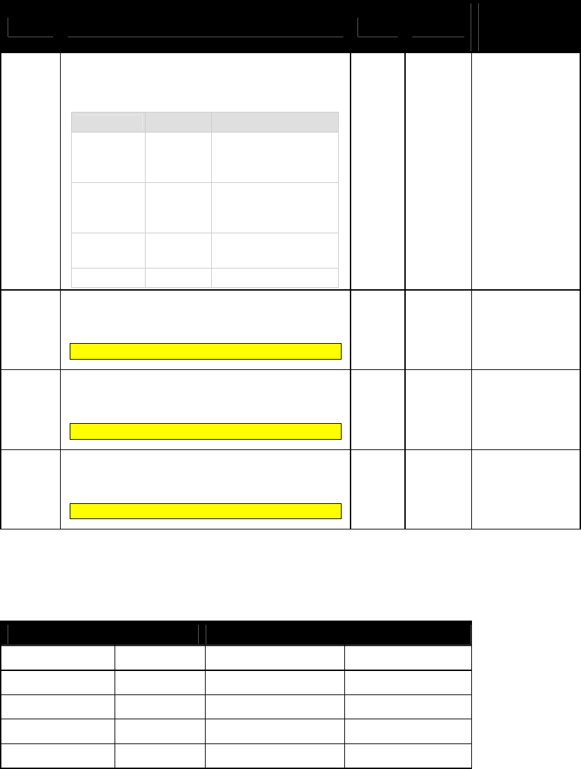
NEO Interface Developers Guide
74
Tag Description Format
Length
Hard-Coded
Default Value in
PayPass Kernel
FFFC[1]
PayPass Profile
Information in this tag is equivalent to PayPass tag
DF811B, although it is formatted slightly
differently:
87654321 Bit Meaning
Values
-------X
MagStripe
Only
0 = normal transaction
1 = MagStripe only
transactions allowed
------X- M/Chip Only
0 = normal transaction
1 = M/Chip only
Transactions allowed
-----X-- On Device
CVM
0 = not supported
1 = supported
XXXXX--- RFU
b 1 00
FFFD[1]
Terminal Action Code (Online)
Reflect the acquirer-selected action to be taken
upon analysis of the TVR.
This is equivalent to MasterCard tag DF8122.
b 5 CC 00 00 00 00
FFFE[1]
Terminal Action Code (Default)
Reflect the acquirer-selected action to be taken
upon analysis of the TVR.
This is equivalent to MasterCard tag DF8120.
b 5 CC 00 00 00 00
FFFF[1]
Terminal Action Code (Denial)
Reflect the acquirer-selected action to be taken
upon analysis of the TVR.
This is equivalent to MasterCard tag DF8121.
b 5 00 00 00 00 00
[1]
These objects use proprietary tags. The use of these tags should be restricted to the serial interface. Once the
Reader has returned an OK Response Frame, the Terminal application should dispose of the tags to avoid conflicts with
other proprietary TLVs.
Table 23: Phone Message Table – Hard-Coded Default Value in Kernel
PCI Mask PCII Value Message Identifier Status
000800 000800 20 (SEE PHONE) 00 (NOT READY)
000400 000400 20 (SEE PHONE) 00 (NOT READY)
000100 000100 20 (SEE PHONE) 00 (NOT READY)
000200 000200 20 (SEE PHONE) 00 (NOT READY)
000000 000000 20 (SEE PHONE) 00 (NOT READY)
NEO Interface Developers Guide
75
American Express Group Configuration TLVs
American Express use Group 2 as default Group. The Set Configurable Group command should be
used to set the TLVs in this section. The following table in this section shows TLVs in American
Express Configuration Group.
Kiosk III rule for American Express Configuration Group:
If a TLV value is absent in American Express Group, reader will use the value in Group 0, except
3 TLVs below:
For Transaction limit(FFF1), CVM limit(FFF5), Floor limit(9F1B): if user-defined TLV Group is
used, user should set these above TLVs in the user-defined Group. If not set, these above TLVs
will be regard as not present.
Vendi rule for American Express Configuration Group:
The following American Express Group TLVs should not be configured for Group 0. The
default American Express group is Group 2. That is, when the reader is configured from the
factory, the American Express System AIDs will be associated with Group 2.
If there are tags in a American Express group that should be set, they must all be set
explicitly, since the absent values are not filled in with Group 0 or Group 1 defaults.
American Express Group tags are instantiated a little differently than other groups. Group 0 is
never used as a default. Refer to the section on American Express Default Group for an
explanation of how the tag database is instantiated for American Express.
Table 24: American Express Default Group 2 Configuration TLVs
Tag Description Format
Length Default Value in
Group 2
5F2A
Transaction Currency Code
Indicates the currency code of the transaction
according to ISO 4217.
Note: make sure you use the same
Transaction Currency Code for all
configurable AIDs. (default = US Dollars)
Note: Kiosk III default value is “09 01”
n3 2 08 40
NEO Interface Developers Guide
76
Tag Description Format
Length Default Value in
Group 2
9A
Transaction Date (YYMMDD)
This value is used to set the Real Time
Clock. Note: The terminal/POS
application should perform range checking
on this value to ensure it is within
acceptable limits.
Note: Kiosk III default value is “not
present”
n6 3
FF FF FF
9C
Transaction Type
Indicates the type of financial transaction,
represented by the first two digits of ISO
8583:1987 Processing Code. (default = purchase
goods or services)
n2 1 00
9F03 Amount Other (Numeric)
n12
6
00 00 00 00 00
00
9F09
Application Version Number
PayPass M/Chip (Value = 00 02)
Amex (Value = 00 01)
Note: Kiosk III default value is 00 02
b
2
00 01
9F1A
Terminal Country Code
Indicates the country code of the terminal,
represented according to ISO 3166. Default = US
Note: Kiosk III default value is “01 58”
n3
2
08 40
9F1B
Terminal Floor Limit
ndicates the floor limit in the terminal for the
AID(s) associated with this group.
Note: The value is the decimal limit amount given in
binary represented in Hex in the
command/response. (60 limit = 6000 decimal =
1770h).
b
4
00 00 17 70
9F21
Transaction Time (HHMMSS)
This value is used to set the Real Time Clock.
Note: The terminal/POS application
should perform range checking on this
value to ensure it is within acceptable
limits.
Note: Kiosk III default value is not
present”
n6
3
FF FF FF
NEO Interface Developers Guide
77
Tag Description Format
Length Default Value in
Group 2
9F33
Terminal Capabilities
Indicates the card data input, CVM, and security
capabilities of the terminal
Default =
• No CVM required
• SDA supported
• DDA supported
• Card Capture
• CDA supported
Note: Kiosk III default value is “00 00 A8”
b
3
00 08 E8
9F35
Terminal Type
Indicates the environment of the terminal, its
communications capability, and its operational
control
Environment
Operational Control
Provided By:
Financial
Institution
Merchant
Cardholder
Attended
Online only
Offline with
online
capability
Offline only
11
12
13
21
22
23
Unattended
Online only
Offl
ine with
online
capability
Offline only
14
15
16
24
25
26
34
35
36
Note: Kiosk III default value is 22
n2
1
25
9F6E
Terminal Transaction Capabilities
Note: Kiosk III default value is “not
present”
b
4
D8 E0 00 00
DF51
ExpressPay Terminal Capabilities
Used to create the ExpressPay Terminal
Capabilities TLV, 9F6D for Amex ExpressPay
applications.
Note: Kiosk III default value is 80
b 1 C0
FFEE1C
UN range
Note: Kiosk III default value is “not
present”
b 4 00 00 00 3C
NEO Interface Developers Guide
78
Tag Description Format
Length Default Value in
Group 2
FFF1[1]
Terminal Contactless Transaction Limit
Indicates the terminal limit for this AID for
Contactless transactions.
Note: Kiosk III default value is 00 00 00 01
00 00
n12
6
00 00 00 01 50
00
FFF5[1]
CVM Required Limit
Indicates the CVM required limit in the terminal
for the associated AIDs.
Note: Kiosk III default value is 00 00 00 00
80 00
n12
6
00 00 00 00 50
00
FFFD[1]
Terminal Action Code (Online)
Reflect the acquirer-selected action to be taken
upon analysis of the TVR.
Note: Kiosk III default value is F8 50 AC F8
00
b
5
00 00 00 00 00
FFFE[1]
Terminal Action Code (Default)
Reflect the acquirer-selected action to be taken
upon analysis of the TVR.
Note: KioskIII default value is F8 50 AC A0
00
b
5
00 00 00 00 00
FFFF[1]
Terminal Action Code (Denial)
Reflect the acquirer-selected action to be taken
upon analysis of the TVR.
b
5
00 00 00 00 00
[1]
These objects use proprietary tags. The use of these tags should be restricted to the serial interface. Once the
Reader has returned an OK Response Frame, the Terminal application should dispose of the tags to avoid conflicts with
other proprietary TLVs.
[2]
These objects only work on the ViVOpay graphic reader.
[3]
These objects only work on the Vendi
AID Configuration Tags
In this table, the “Usage” column indicates when the tag is used. In some cases,
the use may depend on whether a system AID or a user AID is being configured.
The possible usages are:
MAND – this is a mandatory tag when configuring an AID
OPT – this is an optional tag when configuring an AID
NEVER – this tag should never be used for configuring this type of AID (e.g.
“System”)
DEP – this tag is Mandatory depending on how another tag is configured.
For default values of the AID configuration TLVs for each System AID, refer to
the System AID Default Configuration TLVs table in the appendix.
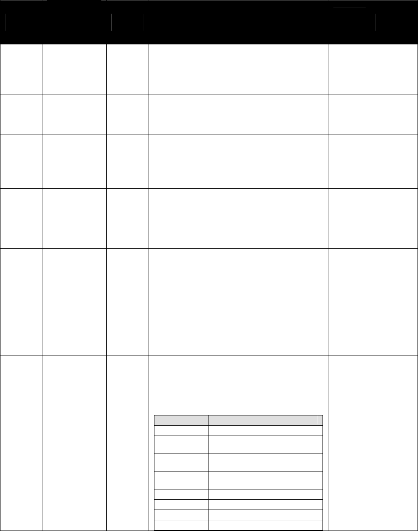
NEO Interface Developers Guide
79
Table 25: AID Configuration TLVs
Tag
Data
Object
Name
Usage
Description Forma
t Length
9F06
Application
Identifier
(AID)
MAND
Identifies the application as described in
ISO/IEC 7816-5.
This must be the 2nd TLV in the data field.
b 5 – 16
DF7C Auto-Switch OPT
Automatically switch to Pass-Through Mode
when PICC is unknown.
00h = disabled (default)
01h = enabled
b 1
FFE0[1]
Registered
Application
Provider
Identifier
(RID)
Sys =
NEVER
User =
OPT
Identifies the payment system to which the
Certification Authority Public Key is
associated. If this Tag is not provided the
first five bytes from the AID are used. b 5
FFE1[1]
Partial
Selection
Allowed
OPT
(Visa
MAND)
Tells the reader to allow partial selection
during the initial select process. 01 =
Allowed, 00 = Disabled
Note: Required for Visa application flow,
this value is set to 01 Allowed and cannot
be changed.
b 1
FFE2[1] Application
Flow
Sys =
NEVER
User =
MAND
1 (01h) – MasterCard MagStripe Application
2 (02h) – American Express Application
3 (03h) – MasterCard PayPass Application
6 (06h) - Visa Application.
13 (0Dh) - Discover Application
14 (0Eh) – JCB QuicPay Application
15 (0Fh) – STAR Application
21 (15h) –Interac Application
23 (17h) –SmartTap
b 1
FFE3 Selection
Features
OPT
Enables or disables selection features. For
M/Chip 3.0, this value will default to 74h.
Please refer to the Selection Features
section for a detailed description of this
tag.
87654321
Selection Feature
-------x
Deprecated / RFU
------x-
Extended Selection
Supported
-----x--
Cardholder Confirmation Not
Supported
----x---
API (application priority
indicator) required
---x----
Invalid AID Allowed
--x-----
Duplicate AID Allowed
-x------
Enable Kernel ID
x-------
RFU
b 1
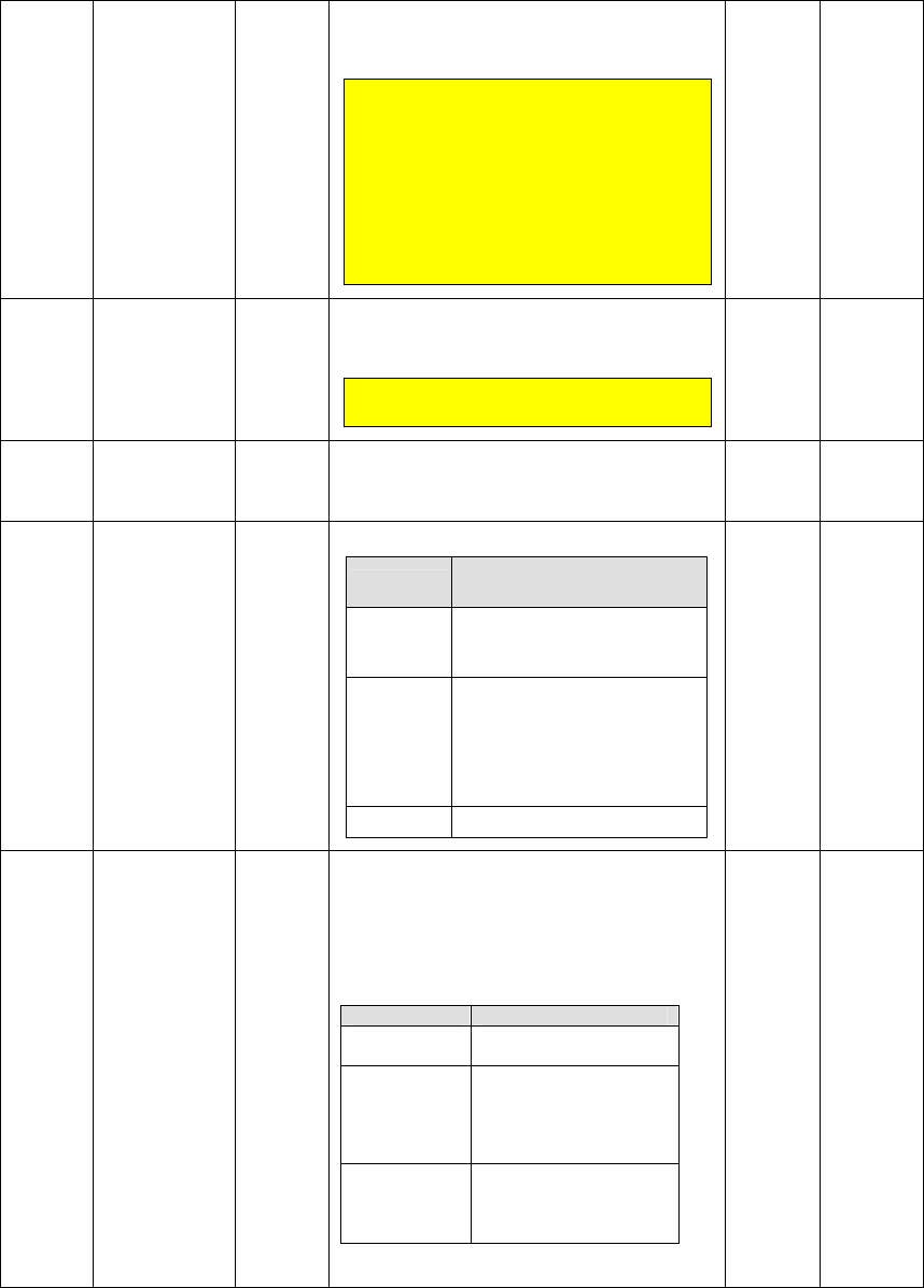
NEO Interface Developers Guide
80
FFE4[1] TLV Group
Number MAND
The TLV Group number that contains the
characteristics for this AID
This must be the 1st TLV in Data Field.
For MasterCard PayPass and any
applications that use the Combined
Selection Feature, this tag represents
the fallback group if the TLV FFE9
transaction type list is empty, or the
kernel ID is disabled (see tag FFE3).
For MasterCard PayPass, this tag may
NOT be Group 0
.
n2 1
FFE5[1] Maximum AID
Length DEP
This value must be <= 16.
For Visa application flow, this value is set
to 16 and cannot be changed.
Note: This tag must be included if the
FFE1 Partial Select TLV is included.
b 1
FFE6[1] AID Disabled OPT
Used to disable a System AID (has no effect
on a User AID). 80h = disabled and 00h =
enabled
b 1
FFE8 Exclude from
Processing OPT
This byte is formatted as follows:
87654321
Meaning (0 = disable, 1 =
enable)
-------x
Exclude from PPSE processing.
1 = This AID will not be added to
the candidate list during PPSE.
------x-
Exclude from Trial and Error
processing. 1 = This AID may
not be added to the candidate
list during Trial and Error
(sometime referred to as “List
of AIDs” processing.
xxxxxx--
RFU
b 1
FFE9 Transaction
Type List OPT
This list defines 3-byte triplets, where the
Kernel ID and transaction type may be used
to identify the group that will be used to
instantiate the dataset for the transaction.
A maximum of 8 entries may appear in this
list. The format of each triplet entry is as
follows:
Byte
Description
1- Kernel ID
Kernel ID as defined by
EMV first byte only.
2-
Transaction
Type
Supported transaction
types may be:
Payment(00), Cash(01),
Cashback(09) or
Refund(20)
3- Group
Number
The group that should
be used for this
transaction and Kernel
ID.
Group 0 may not be used in this list.
b Variable
<= 24
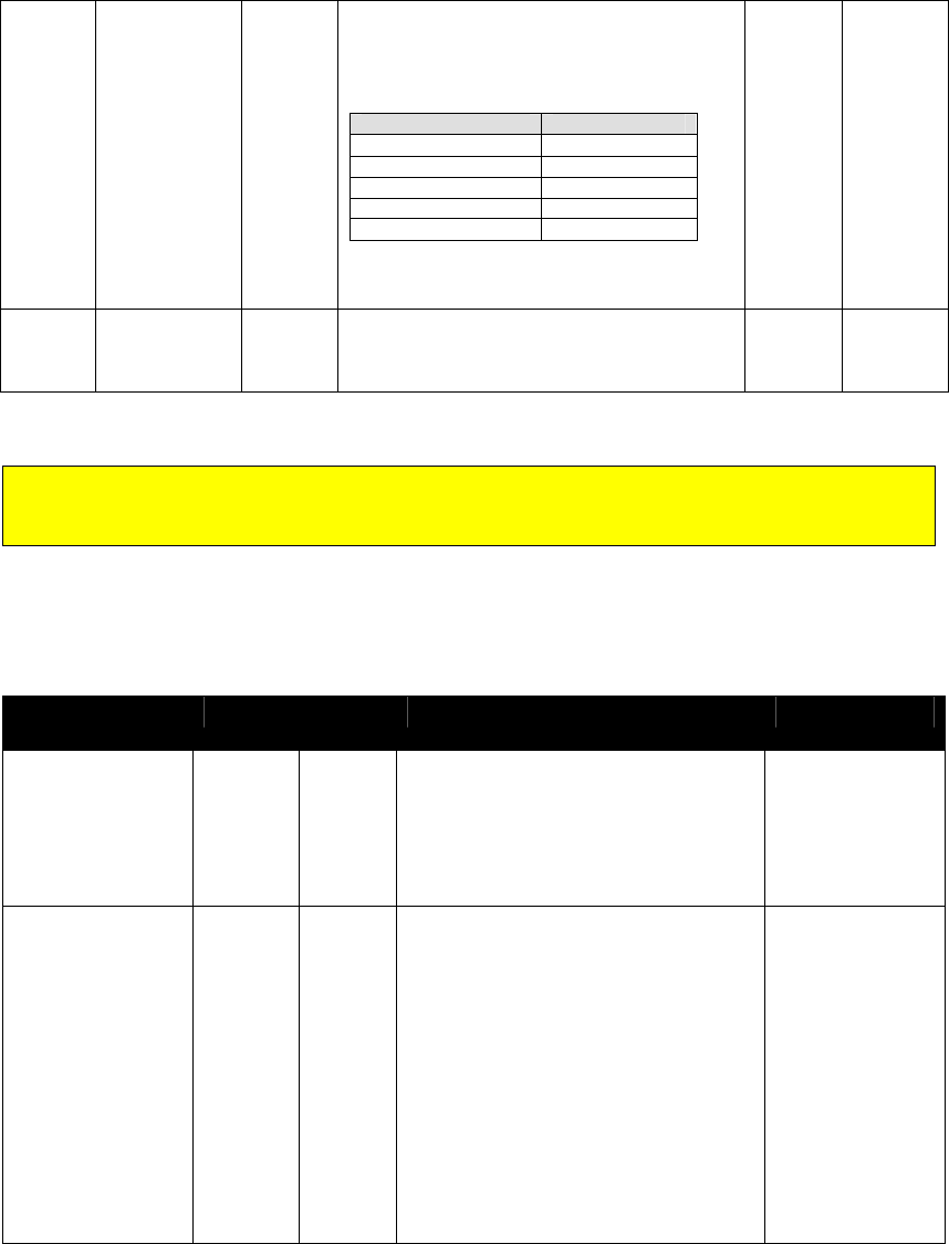
NEO Interface Developers Guide
81
FFEA
Configurable
Kernel
Identifier
OPT
This Kernel Identifier will be used if the
card does not supply a valid Kernel ID
(9F2A). If this tag is not provided, then
default kernel identifiers will be used
depending on the application:
Card Application
Default KID
MasterCard
2
Visa
3
American Express
4
JCB Quickpay
5
All others
0
This tag is equivalent to MasterCard tag
DF810C.
b 1
DFEF2C
Terminal AID
List OPT
Tells the reader to allow Terminal AID List
support during the initial select process. 01
= Allowed, 00 = Disabled b 1
Setting the FFE6 tag may disable an AID. However, the preferred method to disable an AID is
to issue a “Delete Configurable AID” command (04-04). For a system AID, the command will
set the disable bit in FFE6.
The following table lists the System AIDs and the default values for their TLVs
Table 26: System AID Default Configuration TLVs
Name Tag Length
(Hex)
Value (Hex) Card Application
Group
AID
Partial Selection
Application Flow
Max AID Length
FF E4
9F 06
FF E1
FF E2
FF E5
01
06
01
01
01
02
A0 00 00 00 25 01
01
02
10
American Express
Group
AID
Partial Selection
Application Flow
Max AID Length
Selection Features
Transaction Type
List
Kernel ID
FF E4
9F 06
FF E1
FF E2
FF E5
FF E3
FF E9
FF EA
01
07
01
01
01
01
0C
01
01
A0 00 00 00 04 10 10
01
03
10
74
02 00 01
02 20 01
02 01 01
02 09 01
02
MasterCard
PayPass
Application

NEO Interface Developers Guide
82
Name Tag Length
(Hex)
Value (Hex) Card Application
Group
AID
Partial Selection
Application Flow
Max AID Length
Selection Features
FF E4
9F 06
FF E1
FF E2
FF E5
FF E3
01
07
01
01
01
01
00
A0 00 00 00 65 90 01
01
0E
08
14
Note: Vendi default value,
FF E6 = 80
JCB (QUICPay)
Application
Group
AID
Partial Selection
Application Flow
Max AID Length
Selection Features
Transaction Type
List
Kernel ID
FF E4
9F 06
FF E1
FF E2
FF E5
FF E3
FF E9
FF EA
01
07
01
01
01
01
0C
01
01
A0 00 00 00 04 30 60
01
03
10
74
02 00 01
02 20 01
02 01 01
02 09 01
02
MasterCard
PayPass
Application
Group
AID
Application Flow
Partial Selection
Max AID Length
Selection Features
FF E4
9F 06
FF E2
FF E1
FF E5
FF E3
01
07
01
01
01
01
00
A0 00 00 00 03 10 10
06
01
10
14
Visa Application
Group
AID
Application Flow
Partial Selection
Max AID Length
Selection Features
FF E4
9F 06
FF E2
FF E1
FF E5
FF E3
01
07
01
01
01
01
00
A0 00 00 00 03 20 10
06
01
10
14
Visa Application
(Visa Electron)
Group
AID
Application Flow
Partial Selection
Max AID Length
Selection Features
FF E4
9F 06
FF E2
FF E1
FF E5
FF E3
01
07
01
01
01
01
00
A0 00 00 00 03 30 10
06
01
10
14
Visa Application
(Visa Interlink)

NEO Interface Developers Guide
83
Name Tag Length
(Hex)
Value (Hex) Card Application
Group
AID
Application Flow
Partial Selection
Max AID Length
Selection Features
FF E4
9F 06
FF E2
FF E1
FF E5
FF E3
01
07
01
01
01
01
00
A0 00 00 00 03 80 10
06
01
10
14
Visa Application
(Visa Plus)
Group
AID
Application Flow
Partial Selection
Max AID Length
Selection Features
FF E4
9F 06
FF E2
FF E1
FF E5
FF E3
01
07
01
01
01
01
00
A0 00 00 00 65 10 10
06
01
10
14
Note: Vendi default value,
FF E2 = FF
Visa Application
(J/Speedy)
Group
AID
Application Flow
Partial Selection
Max AID Length
Selection Features
FF E4
9F 06
FF E2
FF E1
FF E5
FF E3
01
0A
01
01
01
01
00
A0 00 00 00 02 30 60 D1 58 00
10
01
10
74
Note: Vendi default value,
FF E2 = FF
MXI Application
Group
AID
Application Flow
Partial Selection
Max AID Length
FF E4
9F 06
FF E2
FF E1
FF E5
01
07
01
01
01
00
A0 00 00 03 24 10 10
0D
01
10
Discover
(ZIP)Application
Group
AID
Application Flow
Partial Selection
Max AID Length
FF E4
9F 06
FF E2
FF E1
FF E5
01
07
01
01
01
00
A0 00 00 01 52 30 10
0D
01
10
Discover (D-PAS)
Application
Group
AID
Partial selection
Application Flow
Max AID Length
Selection Features
FF E4
9F 06
FF E1
FF E2
FF E5
FF E3
01
07
01
01
01
01
00
A0 00 00 04 17 01 01
01
0F
08
08
STAR Application

NEO Interface Developers Guide
84
Name Tag Length
(Hex)
Value (Hex) Card Application
Group
AID
Partial selection
Application Flow
Max AID Length
FF E4
9F 06
FF E1
FF E2
FF E5
01
07
01
01
01
00
A0 00 00 02 77 10 10
01
15
10
Note: Vendi default value,
FF E2 = 15
Interac
Application
Group
AID
Partial selection
Application Flow
Max AID Length
FF E4
9F 06
FF E1
FF E2
FF E5
01
07
01
01
01
00
A0 00 00 04 76 D0 00
01
17
10
SmartTap

NEO Interface Developers Guide
85
6.0 Card Application Selection
Combined Selection
The selection of a card application may be based on a Kernel ID, transaction
type and other requirements. The Selection Features tag directs the flow
through the selection logic in the firmware. In addition, the selection of an AID
may be based on a list of transaction types that it supports. Depending on the
transaction type, the AID may be mapped to a different Configurable Group.
This entire process is referred to as “Combined Selection”.
Selection Features (FFE3)
The following table defines each of the bits in the Selection Features tag (FFE3)
and describes how they control the logic flow:
87654321
Feature Name
Description
-------x
Deprecated/RFU
Reserved for Future use.
------x-
Extended Selection
Supported
Allow the Extended Selection value optionally provided by the
card in PPSE to be added to the AID for final selection. The
resulting AID must be less than or equal to 16 bytes or the
candidate will not be added to the candidate list.
0 = the Extended Selection value, if provided by the card, will
not be appended to the AID value for final select.
1 = the Extended Selection value, if provided by the card, will
be appended to the AID value, if it fits (AID + ES <= 16), for use
in final select.
-----x--
Cardholder Confirmation
Not Supported
0 = Cardholder Confirmation is allowed for this AID and if API bit
8 (Cardholder Confirmation) is true, the application will not be
added to the candidate list.
1 = Customer Cardholder Confirmation is not allowed for this
AID, API bit 8 (Cardholder Confirmation) will be ignored.
----x---
API Required
0 = the API is not required for this AID and the application may
be added to the candidate list if the API is missing.
1 = the API is required for this AID; the application will not be
added to the candidate list if the API is missing.
---x----
Invalid AID Allowed
0 = any invalid AID will cause this AID to terminate the
transaction.
1 = any invalid AID will be ignored as related to this AID.
--x-----
Duplicate AID Allowed
0 = a duplicate AID, whether extended or not, is not allowed and
will not be added to the candidate list.
1 = a duplicate AID, whether extended or not, is allowed and
may be added to the candidate list.
-x------
Enable Kernel ID
1 = allow the evaluation of the Kernel ID.
0 = if a Kernel ID is provided by the card it is ignored.
x-------
RFU
Reserved for Future Use.
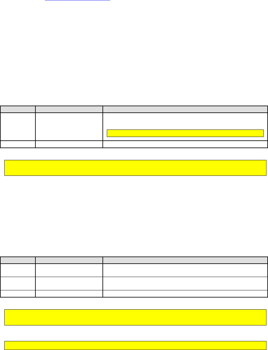
NEO Interface Developers Guide
86
Refer to the System AID Defaults for the configuration of Selection features for
each of the AIDs. If no Selection Features tag (FFE3) is specified, then no
selection features are specified.
Partial Selection (FFE1)
For some applications, an AID on the card may be longer than an AID configured
in the reader. If partial selection is allowed, the AID will be considered a match
if all of the AID configured in the reader matches the first portion of an AID in
the card.
Table 1: Partial Selection (FFE1)
87654321
Value
Description
-------x
Partial selection is
allowed
0 = This AID does not participate in partial selection
1 = This AID will participate in partial selection (default)
For M/Chip 3.0, this value should be set to “allowed”
xxxxxxx-
RFU
Reserved for Future Use
Historically, Partial Selection has been a separate tag. However, it is an integral part of the
selection process, and may be used in conjunction with combined selection features.
AID Participation in Selection Processes (FFE8)
In some cases, applications/AIDs may not be able to participate in some of the
selection processes. For example, some cards/applications do not support PPSE.
The following table describes the bits in tag FFE8 that may be used to exclude
an AID from selection processes.
Table 2: Exclude from Processing (FFE8)
87654321
Process to be Excluded
Description
-------x
Exclude from PPSE
Processing
0 = This AID may be added to the candidate list during PPSE.
1 = This AID will not be added to the candidate list during PPSE.
------x-
Exclude from Trial &
Error Processing
0 = This AID may be added to the candidate list during T&E.
1 = This AID will not be added to the candidate list during T&E.
xxxxxx--
RFU
Reserved for Future Use
“Trial & Error” is sometimes referred to as “List of AIDs”. It is a process by which the reader
will attempt to select an AID by going through its list, hoping for a successful selection.
For M/Chip 3.0, tag FFE8 should be set to 0x00.

NEO Interface Developers Guide
87
Terminal AID List (DFEF2C)
The Terminal AID List Tag DFEF2C is associated with each Terminal AID which
set by the 04-02 (Load AID) command. This tag can control which Terminal AID
should be sent to the card, if the Select AID Command (with PPSE) get “Select
AID Failed”(response SW1/SW2 not 9000 or format error), or the AID list
returned by the card cannot matched by any Terminal AID. One by one, the
terminal will check each Tag DFEF2C associated with the Terminal AID, if the
Tag DFEF2C value is ‘01’, the terminal will send out that Terminal AID data to
the card, contactless transaction can be continued if any Terminal AID matched
by the card; if the Tag DFEF2C value is ‘00’, that terminal AID data will not be
sent.
Table 3: Terminal AID List (DFEF2C)
87654321
Value
Description
-------x
Terminal AID List is
allowed
0 = Terminal will not send out terminal AID data
1 = Terminal will send out terminal AID data
Note: The Terminal AIDs can be modified by 04-02 Load AID
command.
xxxxxxx-
RFU
Reserved for Future Use
NEO Interface Developers Guide
88
7.0 Card Application Specific Behavior
This section contains information specific to a particular card application.
MasterCard PayPass M/Chip
The implementation of MasterCard M/Chip 3.0 is the EMV mode transaction flow.
This includes support for Mag Stripe, but does not include Data Exchange
functionality.
The M/Chip 3.0 implementation incorporates new functionality for:
Balance reading before and after GenAC
Recovery of torn transactions
Support for Certificate Revocation List functions
STOP command processing
Support for defining proprietary tags that are not otherwise handled or
defined in the tag database.
PayPass Default Group
The PayPass implementation required a new data model in which data objects
could be “not present” or “not defined”. As a result, the historical method of
using Group 0 to define default tags could not be used.
Group 0 is no longer used by the PayPass application. The default group for
PayPass applications is Group 1.
In addition to the PayPass default group, the PayPass Kernel also keeps hard-
coded values for a sub-set of the group parameters that are essential for a
transaction. If one of these data items is not available via Activate Transaction
or via Get Configurable Group, then the kernel uses its own hard-coded value
for the ‘Not Present’ data item.
Balance Read Function
The balance may be read from cards that support balance reading. The balance
may be read before or after the Generate AC process. In order to enable
balance reading, the tags for balance read must be defined in the tag database.
This may be accomplished through the Set Configurable Group command or by
including the balance TLVs (DF8104, DF8105) in the Activate command.
For example, if DF8104 is included in the Activate Command, and the card
supports balance reading, then the balance read prior to Generate AC will be
returned in the DF8104 TLV in the Activate response.

NEO Interface Developers Guide
89
Torn Transaction Recovery
A method exists for saving data from a torn transaction and matching up that
transaction with a card that re-appears in the field to complete the transaction.
Due to space limitations in the reader, the maximum number of torn transaction
records that can be retained is two. New tags (configurable in a PayPass Group)
control the size and use of the torn transaction log:
Tag
Name
Description
DF811C
Max Lifetime of Torn
Transaction Record
Controls how long a torn transaction
record can exist in the log before it
expires. It is expressed in seconds.
DF811D
Maximum Number of Torn
Transaction Records
The only possible values are 0, 1 or 2.
If this tag is set to 0, then the torn
transaction recovery is effectively
disabled.
These tags are configurable for PayPass groups. It they are configured for other groups, they
will not be used.
EMV Certificate Revocation List
The MasterCard application can make use of the EMV Certificate Revocation List
features if they are enabled. The DF26 tag is used to enable or disable the
Certificate Revocation List function. The default value for this tag is “enabled”
(1).
Stop Transaction Command
M/Chip 3.02 includes a Stop Transaction Command that is similar to a Cancel
Command. The DF68 tag is used to enable or disable the Stop Command. The
default value for this tag is “disabled” (0).
Proprietary Tag List
The proprietary tag list feature is not specific to MasterCard. Please refer to
the Card Application Proprietary Tag List feature.
PayPass Personalization Limits
To guarantee the successful completion of PayPass transactions using CDA or SDA, size
restrictions noted in this section apply.
7.1.1.1 CDA Transactions
The combined length of the following data objects personalized to the card cannot exceed 2400
bytes. ICC Public Key Certificate
NEO Interface Developers Guide
90
ICC Public Key Exponent
ICC Public Key Remainder
Static data used in data authentication (2048 bytes maximum)
7.1.1.2 SDA Transactions
The combined length of the following data objects personalized to the card cannot be greater
than 2400 bytes.
Signed Static Application Data
Static data used in data authentication (2048 bytes maximum)
NEO Interface Developers Guide
91
8.0 Protocol Command Reference: Protocol 1
Transaction Related Commands
Flush Track Data (17-02)
This command allows the POS application to instruct ViVOpay to flush any Track Data that was
read from a card previously but has not been transferred to the POS yet. On receiving this
command ViVOpay clears any pending card data.
Command Frame from PC to ViVOpay
Byte 0-8
Byte 9
Byte 10
Byte 11
Byte 12
Byte 13
Byte 14
Byte 15
Frame Tag
Frame
Type
Command
Sub-
Command
Data1 Data2
CRC
(LSB)
CRC
(MSB)
ViVOtech\0
‘C’
17h
02h
00
00
ACK Frame from ViVOpay (or NACK)
Byte 0-8
Byte 9
Byte 10
Byte 11
Byte 12
Byte 13
Byte 14
Byte 15
Frame Tag
Frame
Type
Command
Status Data1 Data2
CRC
(MSB)
CRC
(LSB)
ViVOtech\0
‘A’
17h
Status=OK
Unused
XX
Get Full Track Data (17-CD)
Use this command to return full track data from the ViVOpay reader. If a card has been swiped
at the magnetic stripe reader or presented to a reader in Auto Poll mode, ViVOpay sends back
an ACK Frame followed by a Data Frame containing track data. If no card has been swiped or
presented, ViVOpay just returns an ACK Frame and no Data Frame. If both Track 1 and Track 2
data is being returned, then the Data Frame contains the Track 1 Data, followed by a NULL
character (00h) marking the end of Track 1 Data, followed by Track 2 data.
If a card has been swiped, but an error occurred, then ViVOpay just sends an ACK Frame with
Status Failed.
Command Frame from PC to ViVOpay
Byte 0-8
Byte 9
Byte 10
Byte 11
Byte 12
Byte 13
Byte 14
Byte 15
Frame Tag
Frame
Type Command
Sub-
Command
Data1 Data2
CRC
(LSB)
CRC
(MSB)
ViVOtech\0
‘C’
17h
CDh
00
00

NEO Interface Developers Guide
92
Response Frame (ACK)
Byte 0-8
Byte 9
Byte 10
Byte 11
Byte 12
Byte 13
Byte 14
Byte 15
Frame Tag
Frame
Type
Command
Status Data1 Data2
CRC
(MSB)
CRC
(LSB)
ViVOtech\0
‘A’ 17h Status
Tracks/
Error Code
DataLen
Byte 12 is used for Tracks or Error Code, depending on the value of the Status in Byte 11 (see
Status Code Protocol 1). When Status is OK, Byte 12 is used to store Tracks. When Status is
Failed, Byte 12 is used to store the Error Codes from ViVOpay.
Note: These Error Codes are valid only when the RF Error Code Reporting is enabled through
Set RF Error Reporting command, see Set RF Error Reporting.
Table 27: Get Full Track Data Error Codes
Status
Tracks/Error Code
OK
Examples:
Bit 0 = Track 1 Track = 00h => No Track Data
Bit 1 = Track 2 Track = 01h => Track 1 Data Only
Bit 3 = Track 3 Track = 02h => Track 2 Data Only
Track = 03h => Track 1 & Track 2 Data etc.
Bit 7 = Card Type Card Type = 0 => Contactless Card
Card Type = 1 => Swiped Magnetic Stripe
Failed
Error Code = 01h Card Removed
Error Code = 02h Communication Error
Error Code = 03h Protocol Error
Error Code = 04h Multiple Cards Detected
Error Code = 05h Card Not Accepted
Error Code = 06h Bad Data
Error Code = FFh Unknown Error
Other
(See Status Code)
N/A
DataLen
Number of Data Bytes in the Data Frame to Follow. This does not include the Frame Tag, Frame
Type and Checksum bytes.
Data Frame from the Reader to PC (If the Reader sent an ACK and Track Data available)
Byte 0-8
Byte 9
Byte 10
Byte 11
…
Byte n+10
Byte n+11
Byte n+12
Frame Tag
Frame Type
Data 0 Data 1 … Data n
CRC
(MSB)
CRC
(LSB)
ViVOtech\0
‘D’
Data
Data
…
Data
If the host fails to receive the track data, it can send a NACK Frame to request the reader to
resend the track data. To ensure that the reader resends the track data, the NACK Frame must
be received within 500ms after it sends the original track data. If the reader receives the NACK
NEO Interface Developers Guide
93
Frame within that time period, it first resends the ACK Frame followed by the Data Frame to PC.
If the reader receives the NACK Frame after 500ms of sending out the original track data, or if a
new card has been detected, the reader sends an ACK/NACK Frame to the host and does not
resend the track data. Each payload data is only resent once.
Response Frame NACK Frame from PC to the Reader
Byte 0-8
Byte 9
Byte 10
Byte 11
Byte 12
Byte 13
Byte 14
Byte 15
Frame Tag
Frame
Type Command Status Data1 Data2
CRC
(MSB)
CRC
(LSB)
ViVOtech\0
‘N’
17h
00h
00
00
ACK Frame from the Reader
Byte 0-8
Byte 9
Byte 10
Byte 11
Byte 12
Byte 13
Byte 14
Byte 15
Frame Tag
Frame
Type Command
Status Data1 Data2
CRC
(MSB)
CRC
(LSB)
ViVOtech\0
‘A’
17h
Status
Tracks
DataLen
Status
OK (see Status Code Protocol 1)
Tracks Example
Bit 0 = Track 1 Track = 00h => No Track Data
Bit 1 = Track 2 Track = 01h => Track 1 Data Only
Bit 3 = Track 3 Track = 02h => Track 2 Data Only
Track = 03h => Track 1 & Track 2 Data etc.
DataLen
Number of Data Bytes in the Data Frame to Follow. This does not include the Frame Tag, Frame
Type and Checksum bytes.
Data Frame from the Reader to PC (If ViVOpay sent an ACK and Track Data available)
Byte 0-8
Byte 9
Byte 10
Byte 11
…
Byte n+10
Byte n+11
Byte n+12
Frame Tag
Frame Type
Data 0 Data 1 … Data n
CRC
(MSB).
CRC
(LSB).
ViVOtech\0
‘D’
Data
Data
…
Data
An example of the Data Frame sent in response to the Get Full Track data command is as
follows:.
56 69 56 4F 74 65 63 68 00 44 42 35 33 32 35 33
35 30 30 30 30 36 32 33 35 36 37 5E 53 4D 49 54
48 2F 4A 4F 48 4E 5E 30 35 30 38 35 30 31 31 30
NEO Interface Developers Guide
94
30 36 32 36 30 30 34 34 35 30 30 30 30 30 37 38
36 32 30 39 33 33 00 35 33 32 35 33 35 30 30 30
30 36 32 33 35 36 37 3D 30 35 30 38 31 30 31 39
34 34 35 39 39 37 38 36 30 36 32 33 DF 03
Annotated
56 69 56 4F 74 65 63 68 00 – FRAME TAG
44 – FRAME TYPE ‘D’
TRACK 1 DATA
42 35 33 32 35 33 35 30 30 30 30 36 32 33 35 36
37 5E 53 4D 49 54 48 2F 4A 4F 48 4E 5E 30 35 30
38 35 30 31 31 30 30 36 32 36 30 30 34 34 35 30
30 30 30 30 37 38 36 32 30 39 33 33
00 – END OF TRACK 1 START OF TRACK 2
TRACK 2 DATA
35 33 32 35 33 35 30 30 30 30 36 32 33 35 36 37
3D 30 35 30 38 31 30 31 39 34 34 35 39 39 37 38
36 30 36 32 33
DF 03 – CRC
Get ViVOpay Firmware Version (29-00)
Use this command to return the ViVOpay reader’s Firmware Version Number. This is the Protocol
1 version of the command given in Get Version Protocol 2 (29-00). The ViVOpay reader returns
an ACK Frame containing the length of the Version Data. This is followed by a Data Frame
containing the firmware version information.
Command Frame from PC to the Reader
Byte 0-8
Byte 9
Byte 10
Byte 11
Byte 12
Byte 13
Byte 14
Byte 15
Frame Tag
Frame
Type
Command
Sub-
Command
Data1 Data2
CRC
(LSB)
CRC
(MSB)
ViVOtech\0
‘C’
29h
00h
00
00
Response Frame from the Reader (ACK or NACK)
Byte 0-8
Byte 9
Byte 10
Byte 11
Byte 12
Byte 13
Byte 14
Byte 15
Frame Tag
Frame
Type
Command
Status Data1 Data2
CRC
(MSB)
CRC
(LSB)
ViVOtech\0
‘A’
29h
Status=OK
Unused
DataLen
Status = OK (see Status Code Protocol 1)
DataLen = Number of Data Bytes in the Data Frame to Follow. This does not include the Frame
Tag, Frame Type and Checksum bytes.
NEO Interface Developers Guide
95
Data Frame from the Reader to PC (If ViVOpay sent an ACK)
Byte 0-8
Byte 9
Byte 10 … Byte n+10
Byte n+11
Byte n+12
Frame Tag
Frame Type
Data 0 … Data n
CRC
(MSB)
CRC
(LSB)
ViVOtech\0
‘D’
ViVOpay Version (Null Terminated ASCII String)
Key Manager Commands Protocol 1
Note: The following commands use Protocol 1 frame formats. Whenever possible, you should
use the Key Manager commands in Protocol 2.
The Key Management Protocol 1 commands are retained for compatibility purposes and are not
to be used when doing secure communication.
Some ViVOpay firmware versions that support EMV security features provide an EMV Key
Management Interface that can be used by a terminal to Add/Delete CA Public Keys and related
data. These firmware versions also provide a Real Time Clock set up interface and an EMV
ViVOpay Terminal set up interface.
This document describes the ViVOpay Serial Interface, specifically the EMV Key Management
commands, the Real Time Clock set up commands and the EMV ViVOpay Terminal set up
commands. It describes the communication parameters, the ViVOpay Serial Interface Protocol
and the command-specific details.
Warning: DO NOT mix the two Key Management formats. Manage the keys using Protocol 1 or
Protocol 2 but not both.
ViVOpay provides a secure storage environment on its Crypto Chip for storing the Certification
Authority Public Keys. It allows for storage of up to a maximum of 30 keys which are uniquely
identified as a key index in each payment scheme (RID). The basic Key management functions
provided are setting of a new Public Key based on a Unique <RID, Key Index> Pair, and deletion
of a key. Once a key has been stored in the Crypto Chip, it does not allow retrieval of the key.
All authentication/decryption functions that require the key take place inside the Crypto Chip.
The ViVOpay reader periodically checks for Command Frames. Once it starts receiving a
Command Frame, it expects each successive byte to arrive within the inter-byte timeout. If the
ViVOpay reader is receiving multiple Data Frames it expects each successive byte to arrive
within the inter-frame timeout (see table below). If the data is not received within the timeout
period listed, the ViVOpay reader times out and a timeout failure response is sent.
Serial Commands Inter-Byte
Inter-Frame
Delete CA Public Key
200ms
5 sec
Set CA Public Key
200ms
5 sec
Set RTC Date
200ms
5 sec
Set RTC Time
200ms
5 sec
Pass-Through APDU Exchange
200ms
5 sec

NEO Interface Developers Guide
96
(multiple Data Frames)
Pass-Through PCD Single Command
(multiple Data Frames)
200ms
5 sec
All other Commands
200ms
200ms
Once the ViVOpay reader has received a command, the time in which it starts sending a
response back to the terminal varies from command to command, depending on what kind of
processing is required before a response can be sent back to the terminal.
Table 28: EMV Key Management Commands Error Codes – Protocol 1
Error Code Description
00h
No Error
01h
Unknown Error
02h
Invalid Data
03h
Incomplete Data
04h
Invalid Key Index
05h
Invalid CA Hash Algorithm Indicator
06h
Invalid CA Public Key Algorithm Indicator
07h
Invalid CA Public Key Modulus Length
08h
Invalid CA Public Key Exponent
09h
Key already Exists (Try to Set Key after deleting existing Key)
0Ah
No space for New RID
0Bh
Key not Found
0Ch
Crypto Chip not responding
0Dh
Crypto Chip Communication Error
0Eh
RID Key Slots Full
0Fh
No Free Key Slots Available
Set CA Public Key (24-01) Protocol 1
Use this command to send data related to a CA Public Key to the ViVOpay reader for storing in a
secure environment (Crypto Chip Memory). The Public Key is uniquely identified by the <RID,
Key Index> pair. If the total length of the key related data being sent is more than 244 bytes,
then it can be broken down into two Data Frames.
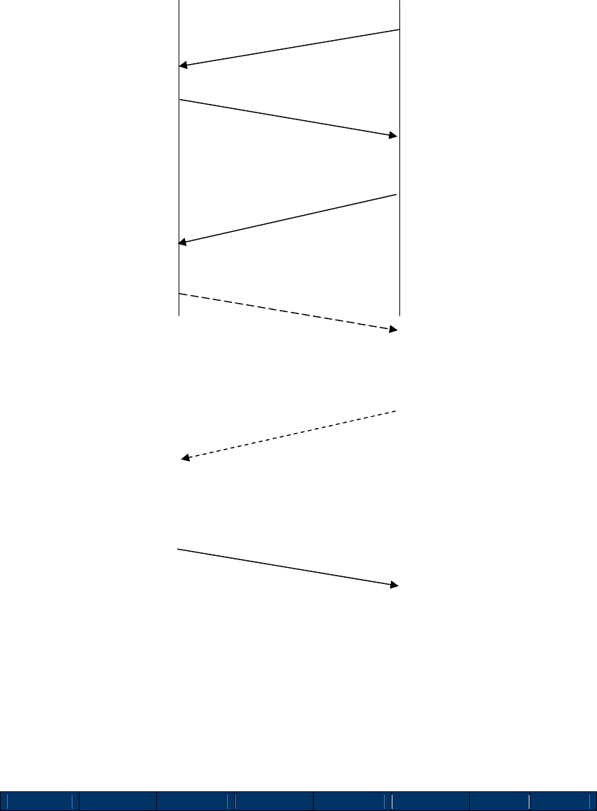
NEO Interface Developers Guide
97
Flow of Frames between ViVOpay Reader and an External Device
Command Frame from Terminal to ViVOpay
Byte 0-8
Byte 9
Byte 10
Byte 11
Byte 12
Byte 13
Byte 14
Byte 15
Final ACK/NACK Frame
ViVOpay
PC / Peripheral
Device
Set Key in
Crypto
Data Frame 1
ACK Frame
Set CA Public Key Cmd
Data Frame 2
ACK Frame
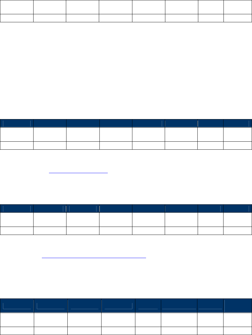
NEO Interface Developers Guide
98
Frame Tag
Frame
Type Command
Sub-
Command
Data1 Data2
CRC
(LSB)
CRC
(MSB)
ViVOtech\0
‘C’
24h
01h
DataLen2
DataLen
DataLen, DataLen2
If the key data is being sent in a single Data Frame, then DataLen contains the length of the
one and only Data Frame to follow and DataLen2 is 0.
If the key data is being sent in two Data Frames, then DataLen contains the length of the
first Data Frame and DataLen2 contain the length of the second Data Frame. The length of
either Data Frame must not exceed 244 (0xF4) bytes.
DataLen > 0, DataLen2 >= 0
ACK Frame from Reader
Byte 0-8
Byte 9
Byte 10
Byte 11
Byte 12
Byte 13
Byte 14
Byte 15
Frame Tag
Frame
Type Command
Status Data1 Data2
CRC
(MSB)
CRC
(LSB)
ViVOtech\0
‘A’
24h
Status
00
00
Status: OK (or see Status Code Protocol 1)
NACK from Reader
Byte 0-8
Byte 9
Byte 10
Byte 11
Byte 12
Byte 13
Byte 14
Byte 15
Frame Tag
Frame
Type
Command
Status Data1 Data2
CRC
(MSB)
CRC
(LSB)
ViVOtech\0
‘N’
24h
FAILED
Error Code
Unused
Error Code: See EMV Key Management Error Codes Table
If at any time ViVOpay sends back a NACK Frame with Status set to Failed, then the Error code
field indicates the reason for failure.
First Data Frame from terminal to Reader (If reader sent an ACK)
Byte 0-8 Byte 9 Byte 10-13
Byte 14 … Byte 10+(n-1)
Byte 10+n
Byte
10+(n+1)
Frame Tag
Frame Type
Data 0 Data 1 … Data (n-1)
CRC
(LSB)
CRC
(MSB)
ViVOtech\0
‘D’
Data
Data
…
Data
Where n = length of the data field.
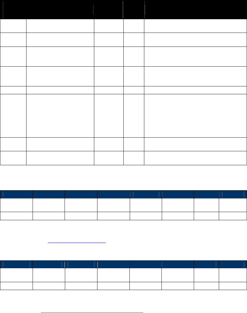
NEO Interface Developers Guide
99
The data field in the first Data Frame contains the complete or partial CA Public Key related
Data. The complete contents and format of the Key Data are given in the following Table. The
data portion of Data Frame 1 and Data Frame 2 (if present) when stripped of the Frame
overhead and concatenated, provides the data as given in the following table.
Table 29: Set CA Public Key Data Field
Data
Byte Name Length
(bytes) Format
Notes
0-4 RID 5 Binary
Registered Identifier.
Necessary for Unique Identification
5 CaPublicKey Index1 1 Binary
Index of the CA Public Key for this RID.
Necessary for Unique Identification
6 CaHashAlgoIndicator1 1 Binary
CA Hash Algorithm to produce Hash-Result
in digital signature scheme. Valid Values:
01h: SHA-1
7 CaPublicKeyAlgoIndicator1 1 Binary
Digital Signature Algorithm to be used with
CA Public Key. Valid Values:
01h: RSA
8-27
CaPublicKeyChecksum1
20
Binary
CA Public Key Checksum
28-31 CaPublicKeyExponent1
4
(PICC-
based
Length may
be 1 or 3)
Binary
CA Public Key Exponent.
Value can be 3 (Len=1 Byte) or
216+1=65537=010001h (Len=3 Bytes).
We consider it as a 32-bit (4-Byte) Big-
Endian number for the Serial Interface and
C
rypto Storage. The PICC may consider it as
a 1-Byte or 3-byte number.
32,33 CaPublicKeyModulusLen 2 Binary
CA Public Key (Modulus) Length stored as a
Big-Endian number. Aka N
CA
34 CaPublicKeyModulus1
Variable
(max 256)
Binary
CA Public Key (Modulus) with Length=NCA
[1]: Fields specified by EMV that need to be stored in Terminal Memory (See EMV2000, Book 2, Section 11.2.2 Table 23)
ACK Frame from Reader
Byte 0-8
Byte 9
Byte 10
Byte 11
Byte 12
Byte 13
Byte 14
Byte 15
Frame Tag
Frame
Type Command
Status Data1 Data2
CRC
(MSB)
CRC
(LSB)
ViVOtech\0
‘A’
24h
Status=OK
00
00
Status: OK (or see Status Code Protocol 1)
NACK from Reader
Byte 0-8
Byte 9
Byte 10
Byte 11
Byte 12
Byte 13
Byte 14
Byte 15
Frame Tag
Frame
Type
Command
Status Data1 Data2
CRC
(MSB)
CRC
(LSB)
ViVOtech\0
‘N’
24h
FAILED
Error Code
Unused
Error Code: See EMV Key Management Error Codes Table
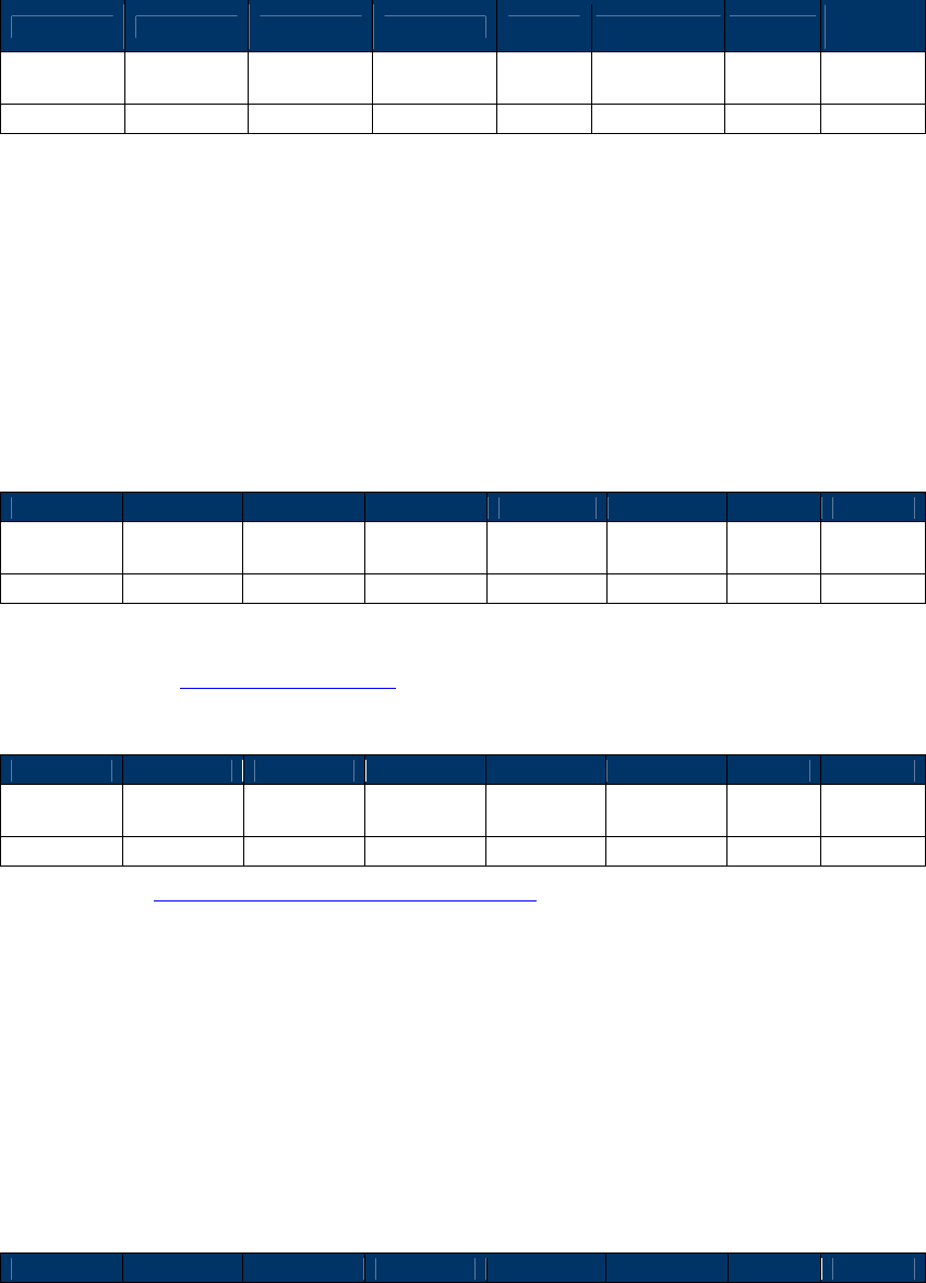
NEO Interface Developers Guide
100
Second Data Frame from terminal to ViVOpay (If the reader sent an ACK, and Data remains to be
sent).
Byte 0-8 Byte 9 Byte 10-13
Byte 14 … Byte 10+(p-1)
Byte 10+p
Byte
10+(p+1)
Frame Tag
Frame Type
Data 0 Data 1 … Data (p-1)
CRC
(LSB)
CRC
(MSB)
ViVOtech\0
‘D’
Data
Data
…
Data
Where p = DataLen2 > 0
If the second Data Frame is sent, then the data field in this frame contains the remaining CA
Public Key related Data.
On receiving valid data, the reader sends it to the Crypto Chip for secure storage. The Crypto
Chip checks the data and stores it in its memory. If the CA Public Key is stored successfully in
the Crypto Chip memory, the reader returns an ACK frame. If for any reason the CA Public Key is
not stored, the reader returns a NACK frame.
Final ACK Frame from Reader
Byte 0-8
Byte 9
Byte 10
Byte 11
Byte 12
Byte 13
Byte 14
Byte 15
Frame Tag
Frame
Type Command
Status Data1 Data2
CRC
(MSB)
CRC
(LSB)
ViVOtech\0
‘A’
24h
Status=OK
00
00
Status: OK (or see Status Code Protocol 1)
Final Nack Frame from Reader
Byte 0-8
Byte 9
Byte 10
Byte 11
Byte 12
Byte 13
Byte 14
Byte 15
Frame Tag
Frame
Type
Command
Status Data1 Data2
CRC
(MSB)
CRC
(LSB)
ViVOtech\0
‘N’
24h
FAILED
Error Code
Unused
Error Code: See EMV Key Management Error Codes Table
Delete CA Public Key (24-02) Protocol 1
Use this command to instruct the ViVOpay reader to delete a previously set CA Public Key from
within secure storage in the Crypto Chip. The Key is uniquely identified by the <RID, Key Index>
pair.
When this command is received, ViVOpay waits for a Data Frame containing the RID and Key
Index. It then instructs the Crypto Chip to delete the specified CA Public Key. Depending on the
result of this operation, the reader returns an ACK or NACK Frame.
Command Frame from Terminal to Reader
Byte 0-8
Byte 9
Byte 10
Byte 11
Byte 12
Byte 13
Byte 14
Byte 15
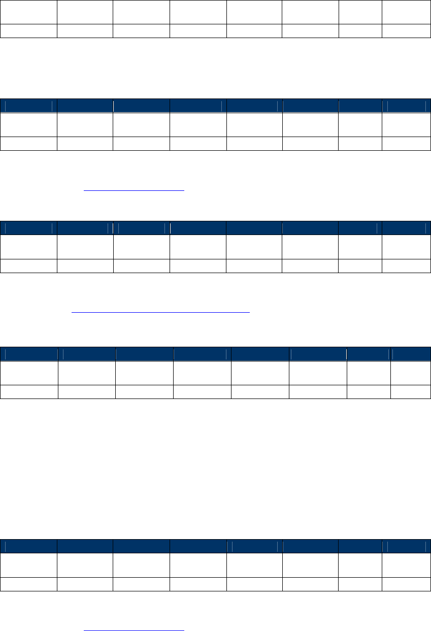
NEO Interface Developers Guide
101
Frame Tag
Frame
Type Command
Sub-
Command
Data1 Data2
CRC
(LSB)
CRC
(MSB)
ViVOtech\0
‘C’
24h
02h
00
DataLen=6
ACK Frame from Reader (or NACK)
ACK Frame
Byte 0-8
Byte 9
Byte 10
Byte 11
Byte 12
Byte 13
Byte 14
Byte 15
Frame Tag
Frame
Type Command
Status Data1 Data2
CRC
(MSB)
CRC
(LSB)
ViVOtech\0
‘A’
24h
Status=OK
00
00
Status: OK (or see Status Code Protocol 1)
NACK Frame
Byte 0-8
Byte 9
Byte 10
Byte 11
Byte 12
Byte 13
Byte 14
Byte 15
Frame Tag
Frame
Type
Command
Status Data1 Data2
CRC
(MSB)
CRC
(LSB)
ViVOtech\0
‘N’
24h
FAILED
Error Code
Unused
Error Code: See EMV Key Management Error Codes Table
Data Frame from Terminal to Reader (If reader sent an ACK)
Byte 0-8
Byte 9
Byte 10
…
Byte 14
Byte 15
Byte 16
Byte 17
Frame Tag
Frame Type
Data 0 … Data 4 Data 5
CRC
(LSB)
CRC
(MSB)
ViVOtech\0
‘D’
RID [0]
…
RID [4]
Key Index
RID: Registered Identifier (5 Bytes)
Key Index: Key Index (1 Byte)
The RID, together with the Key Index specifies a unique Key stored in ViVOpay Secure Memory.
Final ACK Frame from Reader
Byte 0-8
Byte 9
Byte 10
Byte 11
Byte 12
Byte 13
Byte 14
Byte 15
Frame Tag
Frame
Type
Command
Status Data1 Data2
CRC
(MSB)
CRC
(LSB)
ViVOtech\0
‘A’
24h
Status=OK
00
00
Status: OK (or see Status Code Protocol 1)
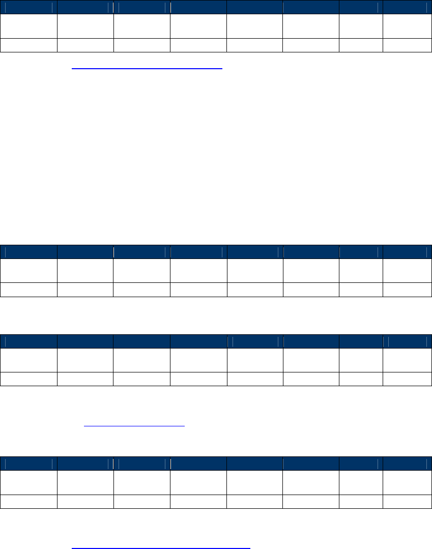
NEO Interface Developers Guide
102
Final NACK Frame from Reader
Byte 0-8
Byte 9
Byte 10
Byte 11
Byte 12
Byte 13
Byte 14
Byte 15
Frame Tag
Frame
Type Command
Status Data1 Data2
CRC
(MSB)
CRC
(LSB)
ViVOtech\0
‘N’
24h
FAILED
Error Code
Unused
Error Code: See EMV Key Management Error Codes
Delete All CA Public Keys (24-03) Protocol 1
Use this command to instruct the ViVOpay reader to delete all previously set CA Public Keys
from within secure storage in the Crypto Chip. The Keys is deleted regardless of the <RID, Key
Index> pair.
When this command is received, the reader instructs the Crypto Chip to delete all CA Public
Keys. Depending on the result of this operation, the reader returns an ACK or NACK Frame.
Command Frame from Terminal to Reader
Byte 0-8
Byte 9
Byte 10
Byte 11
Byte 12
Byte 13
Byte 14
Byte 15
Frame Tag
Frame
Type Command
Sub-
Command
Data1 Data2
CRC
(LSB)
CRC
(MSB)
ViVOtech\0
‘C’
24h
03h
00
00
ACK Frame from Reader
Byte 0-8
Byte 9
Byte 10
Byte 11
Byte 12
Byte 13
Byte 14
Byte 15
Frame Tag
Frame
Type Command
Status Data1 Data2
CRC
(MSB)
CRC
(LSB)
ViVOtech\0
‘A’
24h
Status=OK
00
00
Status: OK (or see Status Code Protocol 1)
NACK Frame from Reader
Byte 0-8
Byte 9
Byte 10
Byte 11
Byte 12
Byte 13
Byte 14
Byte 15
Frame Tag
Frame
Type
Command
Status Data1 Data2
CRC
(MSB)
CRC
(LSB)
ViVOtech\0
‘N’
24h
FAILED
Error Code
Unused
Error Code: See EMV Key Management Error Codes Table

NEO Interface Developers Guide
103
Miscellaneous Protocol 1 Commands
Set RF Error Reporting (17-03)
This command allows the POS application to Enable/Disable RF Error Code Reporting for the Get
Full Track Data command. When RF Error Code Reporting is enabled, if there is any RF error
code, it is reported to the POS application through the ACK Frame for Get Full Track Data
command (see Get Full Track Data).
Command Frame from PC to the Reader
Byte 0-8
Byte 9
Byte 10
Byte 11
Byte 12
Byte 13
Byte 14
Byte 15
Frame Tag
Frame
Type Command
Sub-
Command
Data1 Data2
CRC
(LSB)
CRC
(MSB)
ViVOtech\0
‘C’ 17h 03h
Operation
Code XX
Operation Code:
00h: Disable RF Error Code Reporting
01h: Enable RF Error Code Reporting
02h or others: No change
ACK Frame from the Reader
Byte 0-8
Byte 9
Byte 10
Byte 11
Byte 12
Byte 13
Byte 14
Byte 15
Frame Tag
Frame
Type Command
Status Data1 Data2
CRC
(MSB)
CRC
(LSB)
ViVOtech\0
‘A’ 17h Status=OK
RF Error Code
Reporting
Status
XX
RF Error Code Reporting Status (only for ACK frame):
00h: RF Error Code Reporting disabled
01h: RF Error Code Reporting enabled
RTC (Real Time Clock) Set Up Commands
On ViVOpay readers that support EMV, the Real Time Clock must be configured with the correct
local date and time for the region in which it is used. The RTC commands allow a terminal to
check the date and time on a ViVOpay reader and change it if required.
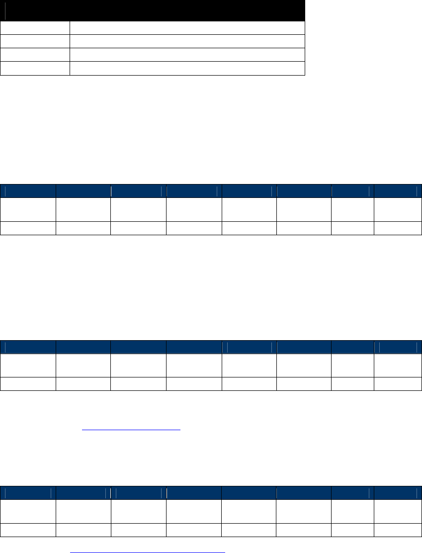
NEO Interface Developers Guide
104
Table 30: Error Codes for RTC Management Commands
Error Code Description
00h
No Error
01h
Unknown Error
02h
Invalid Data
03h
RTC not found or not responding
RTC Set Time (25-01)
Use this command to instruct the ViVOpay reader to set a specific time in the Real Time Clock.
Command Frame from Terminal to Reader
Byte 0-8
Byte 9
Byte 10
Byte 11
Byte 12
Byte 13
Byte 14
Byte 15
Frame Tag
Frame
Type
Command
Sub-
Command
Data1 Data2
CRC
(LSB)
CRC
(MSB)
ViVOtech\0
‘C’
25h
01h
HH
MM
HH: Hour (2-digit, BCD, Range 00-23)
MM: Minutes (2-digit, BCD, Range 00-59)
ACK Frame from Reader
Byte 0-8
Byte 9
Byte 10
Byte 11
Byte 12
Byte 13
Byte 14
Byte 15
Frame Tag
Frame
Type Command
Status Data1 Data2
CRC
(MSB)
CRC
(LSB)
ViVOtech\0
‘A’
25h
Status=OK
00
00
Status: OK (or see Status Code Protocol 1)
NACK Frame from Reader
Byte 0-8
Byte 9
Byte 10
Byte 11
Byte 12
Byte 13
Byte 14
Byte 15
Frame Tag
Frame
Type
Command
Status Data1 Data2
CRC
(MSB)
CRC
(LSB)
ViVOtech\0
‘N’
25h
FAILED
Error Code
Unused
Error Code: See RTC Management Error Codes Table
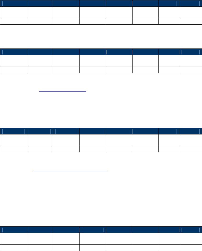
NEO Interface Developers Guide
105
RTC Get Time (25-02)
Use this command to instruct the ViVOpay reader to return the current time from the Real Time
Clock.
Command Frame from Terminal to Reader
Byte 0-8
Byte 9
Byte 10
Byte 11
Byte 12
Byte 13
Byte 14
Byte 15
Frame Tag
Frame
Type
Command
Sub-
Command
Data1 Data2
CRC
(LSB)
CRC
(MSB)
ViVOtech\0
‘C’
25h
02h
00
00
ACK Frame from Reader
Byte 0-8
Byte 9
Byte 10
Byte 11
Byte 12
Byte 13
Byte 14
Byte 15
Frame Tag
Frame
Type
Command
Status Data1 Data2
CRC
(MSB)
CRC
(LSB)
ViVOtech\0
‘A’
25h
Status=OK
HH
MM
Status: OK (or see Status Code Protocol 1)
HH: Hour (2-digit, BCD, Range 00-23)
MM: Minutes (2-digit, BCD, Range 00-59)
NACK Frame from Reader
Byte 0-8
Byte 9
Byte 10
Byte 11
Byte 12
Byte 13
Byte 14
Byte 15
Frame Tag
Frame
Type
Command
Status Data1 Data2
CRC
(MSB)
CRC
(LSB)
ViVOtech\0
‘N’
25h
FAILED
Error Code
Unused
Error Code: See RTC Management Error Codes Table
RTC Set Date (25-03)
Use this command to instruct the ViVOpay reader to set a specific Date in the Real Time Clock.
Command Frame from Terminal to Reader
Byte 0-8
Byte 9
Byte 10
Byte 11
Byte 12
Byte 13
Byte 14
Byte 15
Frame Tag
Frame
Type
Command
Sub-
Command
Data1 Data2
CRC
(LSB)
CRC
(MSB)
ViVOtech\0
‘C’
25h
03h
00
DataLen=4
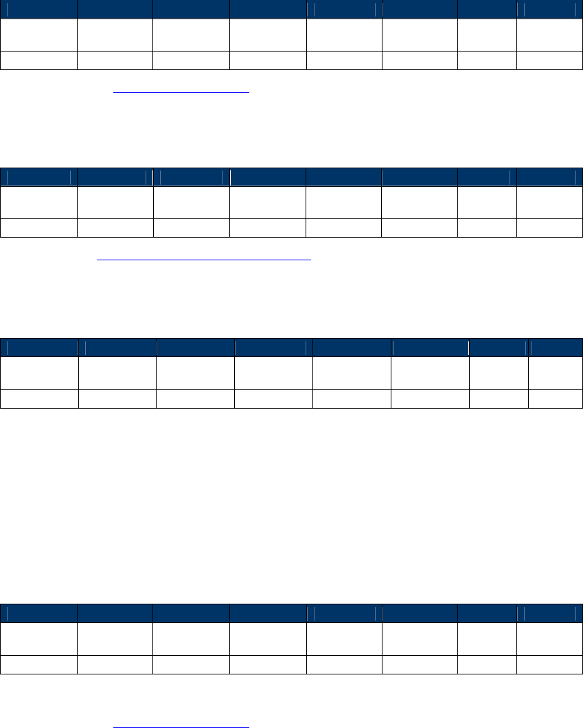
NEO Interface Developers Guide
106
DataLen
If the key data is being sent in a single Data Frame, then DataLen contains the length of the
one and only Data Frame to follow and DataLen2 is 0.
If the key data is being sent in two Data Frames, then DataLen contains the length of the
first Data Frame and DataLen2 contain the length of the second Data Frame. The length of
either Data Frame must not exceed 244 (0xF4) bytes.
DataLen > 0, DataLen2 >= 0
ACK Frame from Reader
Byte 0-8
Byte 9
Byte 10
Byte 11
Byte 12
Byte 13
Byte 14
Byte 15
Frame Tag
Frame
Type
Command
Status Data1 Data2
CRC
(MSB)
CRC
(LSB)
ViVOtech\0
‘A’
25h
Status=OK
00
00
Status: OK (or see Status Code Protocol 1)
NACK Frame from Reader
Byte 0-8
Byte 9
Byte 10
Byte 11
Byte 12
Byte 13
Byte 14
Byte 15
Frame Tag
Frame
Type
Command
Status Data1 Data2
CRC
(MSB)
CRC
(LSB)
ViVOtech\0
‘N’
25h
FAILED
Error Code
Unused
Error Code: See RTC Management Error Codes Table
Data Frame from Terminal to Reader (If the reader sent an ACK)
Byte 0-8
Byte 9
Byte 10
Byte 11
Byte 12
Byte 13
Byte 14
Byte 15
Frame Tag
Frame Type
Data 0 Data 1 Data 2 Data 3
CRC
(LSB)
CRC
(MSB)
ViVOtech\0
‘D’
YY1
YY2
MM
DD
YY1: Year (Higher Century Byte) (2-Digit, BCD, Range 00-99)
YY2: Year (Lower Byte) (2-Digit, BCD, Range 00-99)
MM: Month (2-Digit, BCD, Range 01-12)
DD: Date (2-Digit, BCD, Range 01-31)
Final ACK Frame from Reader
Byte 0-8
Byte 9
Byte 10
Byte 11
Byte 12
Byte 13
Byte 14
Byte 15
Frame Tag
Frame
Type Command
Status Data1 Data2
CRC
(MSB)
CRC
(LSB)
ViVOtech\0
‘A’
25h
Status=OK
00
00
Status: OK (or see Status Code Protocol 1)
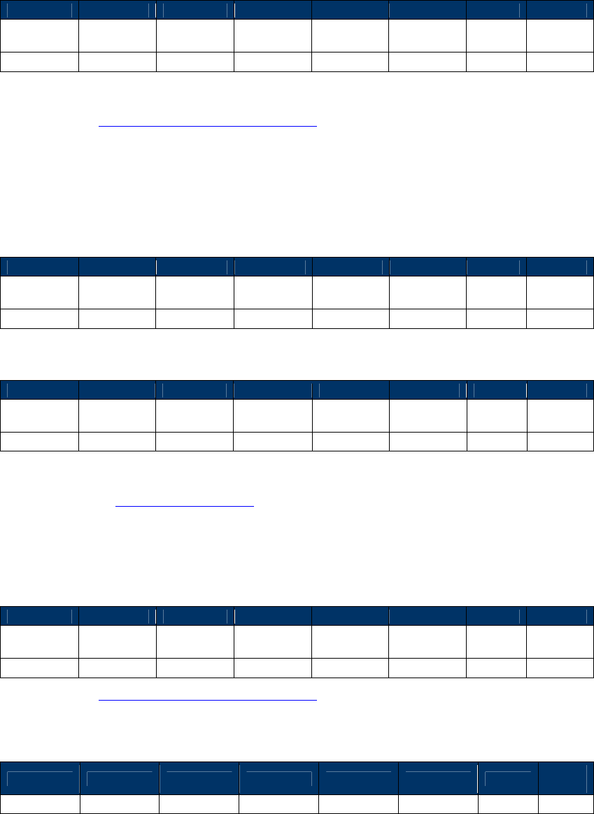
NEO Interface Developers Guide
107
Final NACK Frame from Reader
Byte 0-8
Byte 9
Byte 10
Byte 11
Byte 12
Byte 13
Byte 14
Byte 15
Frame Tag
Frame
Type Command
Status Data1 Data2
CRC
(MSB)
CRC
(LSB)
ViVOtech\0
‘N’
25h
FAILED
Error Code
Unused
Error Code: See RTC Management Error Codes Table
RTC Get Date (25-04)
This command returns the reader’s the current Date from the Real Time Clock.
Command Frame from Terminal to Reader
Byte 0-8
Byte 9
Byte 10
Byte 11
Byte 12
Byte 13
Byte 14
Byte 15
Frame Tag
Frame
Type Command
Sub-
Command
Data1 Data2
CRC
(LSB)
CRC
(MSB)
ViVOtech\0
‘C’
25h
04h
00
00
ACK Frame from Reader
Byte 0-8
Byte 9
Byte 10
Byte 11
Byte 12
Byte 13
Byte 14
Byte 15
Frame Tag
Frame
Type Command
Status Data1 Data2
CRC
(MSB)
CRC
(LSB)
ViVOtech\0
‘A’
25h
Status=OK
Unused
DataLen
Status: OK (or see Status Code Protocol 1)
DataLen
Number of Data Bytes in the Data Frame to Follow. This does not include the Frame Tag,
Frame Type and Checksum bytes. This is either 0 (if Date is not being returned) or 4.
NACK Frame from Reader
Byte 0-8
Byte 9
Byte 10
Byte 11
Byte 12
Byte 13
Byte 14
Byte 15
Frame Tag
Frame
Type Command
Status Data1 Data2
CRC
(MSB)
CRC
(LSB)
ViVOtech\0
‘N’
25h
FAILED
Error Code
Unused
Error Code: See RTC Management Error Codes Table
Data Frame from ViVOpay to terminal (If ViVOpay sent an ACK)
Byte 0-8 Byte 9 Byte 10 Byte 11 Byte 12 Byte 13 Byte 14
Byte
15
Frame Tag
Frame Type
Data 0
Data 1
Data 2
Data n
CRC
CRC

NEO Interface Developers Guide
108
(MSB)
(LSB)
ViVOtech\0
‘D’
YY1
YY2
MM
DD
YY1: Year (Higher Century Byte) (2-Digit, BCD, Range 00-99)
YY2: Year (Lower Byte) (2-Digit, BCD, Range 00-99)
MM: Month (2-Digit, BCD, Range 01-12)
DD: Date (2-Digit, BCD, Range 01-31)
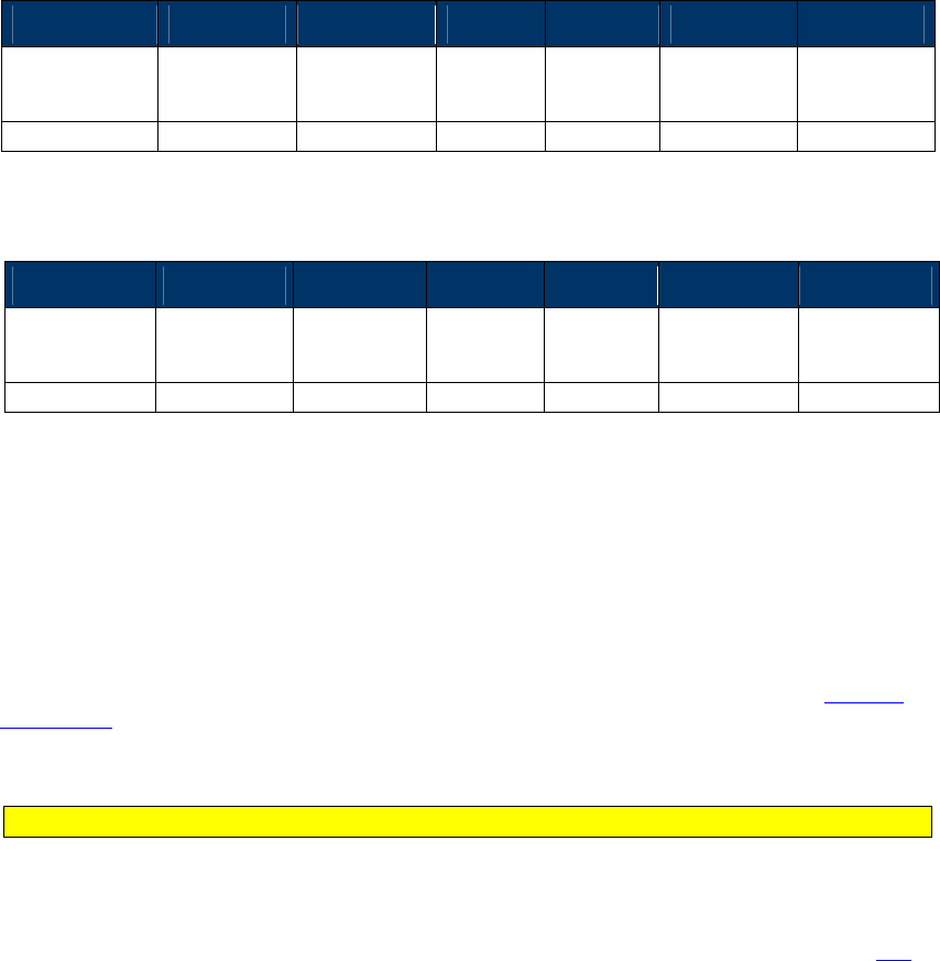
NEO Interface Developers Guide
109
9.0 Protocol Command Reference: Protocol 2
General Commands
Ping (18-01)
Use the Ping command to check if the ViVOpay reader is connected to the terminal. If the
ViVOpay reader is connected, it responds with a valid Response Frame, otherwise there is no
response.
Command Frame
Byte 0-9 Byte 10 Byte 11 Byte 12 Byte 13 Byte 14 Byte 15
Header Tag &
Protocol
Version
Command Sub-
Command
Data
Length
(MSB)
Data
Length
(LSB)
CRC (LSB) CRC (MSB)
ViVOtech2\0
18h
01h
00h
00h
B3
CD
Response Frame
Byte 0-9 Byte 10 Byte 11 Byte 12 Byte 13 Byte 14 Byte 15
Header Tag &
Protocol
Version
Command Status Code
Data
Length
(MSB)
Data
Length
(LSB)
CRC (MSB) CRC (LSB)
ViVOtech2\0
18h
00h
00h
00h
FA
83
Set Poll Mode (01-01)
The Set Poll Mode command allows the terminal to set the ViVOpay reader polling mode. The
ViVOpay reader functions in one of two polling modes: “Auto Poll” or “Poll on Demand”. The
value is saved in nonvolatile memory so you only need to send this command when you want to
change the mode.
The ViVOpay reader operates in Poll on Demand mode by default. Use the Poll on Demand mode
when you want the reader to poll for cards only when requested to by the terminal. In this mode
the ViVOpay reader remains in the idle state with the RF field off until it receives an Activate
Transaction command. Once the transaction is completed (or the reader times out while polling)
the reader returns to the idle state. This mode allows the terminal to send data to the reader
before the card data is read, as required for EMV transactions.
Note: KioskIII operates in AutoPoll mode by default.
In Auto Poll mode, the RF field is always active and the reader continuously polls for the
presence of a contactless card. There is no requirement for the terminal to initiate a
transaction. When a supported contactless MagStripe card is detected, the Track data can be
sent out on the MagStripe interface (if the ViVOpay unit supports it) or retrieved using the Get
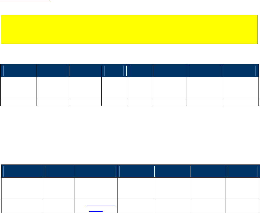
NEO Interface Developers Guide
110
Transaction Result command. The Auto Poll mode is required in environments where the
ViVOpay reader is connected to a POS terminal via the terminal’s MagStripe interface.
Warning: EMEA UI is intended for use in the EMV or European environment, where the reader
is not allowed to poll continuously (e.g., operate in Auto Poll Mode). The reader does NOT
support Auto Poll while in EMEA UI mode and has the potential for aberrant or unstable
behavior. The reader is not certified to work properly in this situation.
Command Frame
Byte 0-9 Byte 10 Byte 11 Byte 12
Byte 13
Byte 14 Byte 14+n Byte 15+n
Header Tag
& Protocol
Version
Command
Sub-
Command
Data
Length
(MSB)
Data
Length
(LSB)
Data CRC (LSB) CRC (MSB)
ViVOtech2\0
01h
01h
00h
01h
Poll Mode
Poll Mode
00h = Auto Poll
01h = Poll on Demand
Response Frame
Byte 0-9 Byte 10 Byte 11 Byte 12 Byte 13 Byte 14 Byte 15
Header Tag &
Protocol
Version
Command
Status Code Data Length
(MSB)
Data Length
(LSB) CRC (MSB) CRC (LSB)
ViVOtech2\0 01h
See Status Code
Table
00h 00h
The Poll Mode has been set to the requested mode only if the Response Frame contains an OK
Status Code. No data is returned in the response.
Control User Interface (01-02)
Use the Control User Interface command to instruct the reader to display a message, change
LED behavior, and beep. Each action is controlled independently by values in the data field of
the command. This allows you to instruct the reader to beep when it displays a message. To
display messages, the reader must be in Poll on Demand mode. Readers without a display can
use this command to control the buzzer and LEDs.
There are three cases depending on the LCD Message index number:
Indexes 00h to 07h correspond to messages that are automatically displayed by the
reader. In most cases, you do not use the terminal to trigger these messages.
Indexes 08h to 0Bh are messages that are triggered by the terminal.
Index FFh indicates that the command is only setting the buzzer and/or LEDs. No
message is displayed.

NEO Interface Developers Guide
111
After completion of a successful transaction, the "Thank You" message remains on the LCD until
the terminal sends a new Control User Interface command.
Command Frame
Byte 0-9 Byte 10 Byte 11 Byte 12
Byte 13
Byte 14 …
Byte 14+n-1 Byte 14+n
Byte 15+n
Header Tag
& Protocol
Version
Command
Sub-
Command
Data
Length
(MSB)
Data
Length
(LSB)
Data CRC (LSB)
CRC (MSB)
ViVOtech2\0
01h
02h
00h
04h
See Data Table
The format and contents of the data field in the Command Frame are given in the following
table.
Table 31: Control User Interface Data
Data Item
Length
(bytes)
Description
LCD Message
Index
1
Messages 00-07 are normally controlled by the reader.
00: Idle Message (Welcome)
01: Present card (Please Present Card)
02: Time Out or Transaction cancel (No Card)
03: Transaction between reader and card is in the middle (Processing…)
04: Transaction Pass (Thank You)
05: Transaction Fail (Fail)
06: Amount (Amount $ 0.00 Tap Card)
07: Balance or Offline Available funds (Balance $ 0.00)
Messages 08-0B are controlled by the terminal
08: Insert or Swipe card (Use Chip & PIN)
09: Try Again(Tap Again)
0A: Tells the customer to present only one card (Present 1 card only)
0B: Tells the customer to wait for authentication/authorization (Wait)
FF indicates the command is setting the LED/Buzzer only.
Beep Indicator 1
00h: No beep
01h: Single beep
02h: Double beep
03h: Three short beeps
04h: Four short beeps
05h: One long beep of 200 ms
06h: One long beep of 400 ms
07h: One long beep of 600 ms
08h: One long beep of 800 ms
LED Number 1
00h: LED 0 (Power LED)
01h: LED 1
02h: LED 2
03h: LED 3
FFh: All LEDs
Where the LEDs are numbered 0, 1, 2, 3 counting from the left.
Note: You can attempt to control the Power LED (LED 0) but other UI
behavior takes control, so attempting to manipulate the Power LED in
non-pass-through mode has no effect.
LED Status 1
00h: LED Off
01h: LED On
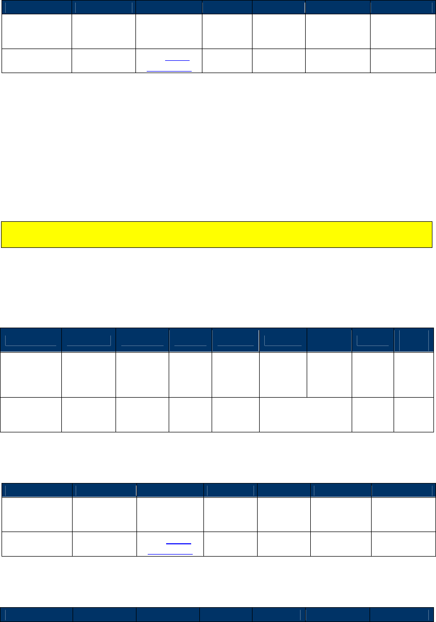
NEO Interface Developers Guide
112
Response Frame
Byte 0-9
Byte 10
Byte 11
Byte 12
Byte 13
Byte 14
Byte 15
Header Tag &
Protocol
Version
Command Status Code
Data
Length
(MSB)
Data
Length
(LSB)
CRC (MSB) CRC (LSB)
ViVOtech2\0 01h
See Status
Code Table
00h 00h
If the Status Code does not return OK, the command failed.
Set/Get Source for RTC/LCD/Buzzer/LED (01-05)
Use this command to set up or get the source for RTC/LCD/Buzzer/LED on the ViVOpay reader.
The reader can be configured to use internal source or external source for RTC/Buzzer/LED
control. If necessary, the reader can be configured to use both internal and external source
except for the RTC.
Note: ViVOpay reader may not support all these options. Careful attention must be given to
these details.
When the data length is 02h, the command is used to set up the source configuration for
RTC/LCD/Buzzer/LED; when the data length is 0, the current source configuration shall be
returned in the Response Frame.
Command Frame (Set Source)
Byte 0-9 Byte 10 Byte 11 Byte 12
Byte 13
Byte 14
Byte 15
Byte 16
Byte
17
Header Tag
& Protocol
Version
Command
Sub-
Command
Data
Length
(MSB)
Data
Length
(LSB)
Data
Byte1
Data
Byte2
CRC
(LSB)
CRC
(MSB)
ViVOtech2\0
01h 05h 00h 02h
Bitmap for
RTC/LCD/Buzzer/
LED
Response Frame (Set Source)
Byte 0-9
Byte 10
Byte 11
Byte 12
Byte 13
Byte 14
Byte 15
Header Tag &
Protocol
Version
Command Status Code
Data
Length
(MSB)
Data
Length
(LSB)
CRC (MSB) CRC (LSB)
ViVOtech2\0 01h
See Status
Code Table 00h 00h
Command Frame (Get Source)
Byte 0-9
Byte 10
Byte 11
Byte 12
Byte 13
Byte 14
Byte 15
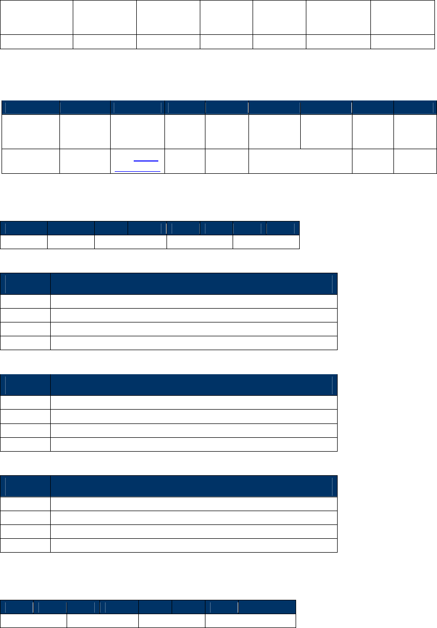
NEO Interface Developers Guide
113
Header Tag &
Protocol
Version
Command Sub-
Command
Data
Length
(MSB)
Data
Length
(LSB)
CRC (LSB) CRC (MSB)
ViVOtech2\0
01h
05h
00h
00h
Response Frame (Get Source)
Byte 0-9
Byte 10
Byte 11
Byte 12
Byte 13
Byte 14
Byte 15
Byte 16
Byte 17
Header Tag
& Protocol
Version
Command
Status
Code
Data
Length
(MSB)
Data
Length
(LSB)
Data Byte1
Data Byte2
CRC
(MSB)
CRC
(LSB)
ViVOtech2\0
01h
See Status
Code Table
00h 02h
Bitmap for
RTC/LCD/Buzzer/LED
Data Byte1 Definition:
Bit7
Bit6
Bit5
Bit4
Bit3
Bit2
Bit1
Bit0
Reserved
Reserved
RTC
LCD
Buzzer
Bit1 Bit0 Description
00
Don’t use Buzzer
01
Use Buzzer from ViVOpay reader
10
Use Buzzer from external source
11
Use Buzzer from both reader and external source
Bit3 Bit2 Description
00
Don’t use LCD
01
Use LCD from ViVOpay reader
10
Use LCD from external source
11
Use LCD from both reader and external source
Bit5 Bit4 Description
00
Don’t use RTC
01
Use RTC from ViVOpay reader
10
Not allowed
11
Not allowed
Data Byte2 Definition:
Bit7
Bit6
Bit5
Bit4
Bit3
Bit2
Bit1
Bit0
Reserved
Reserved
Power LED
Transaction LED
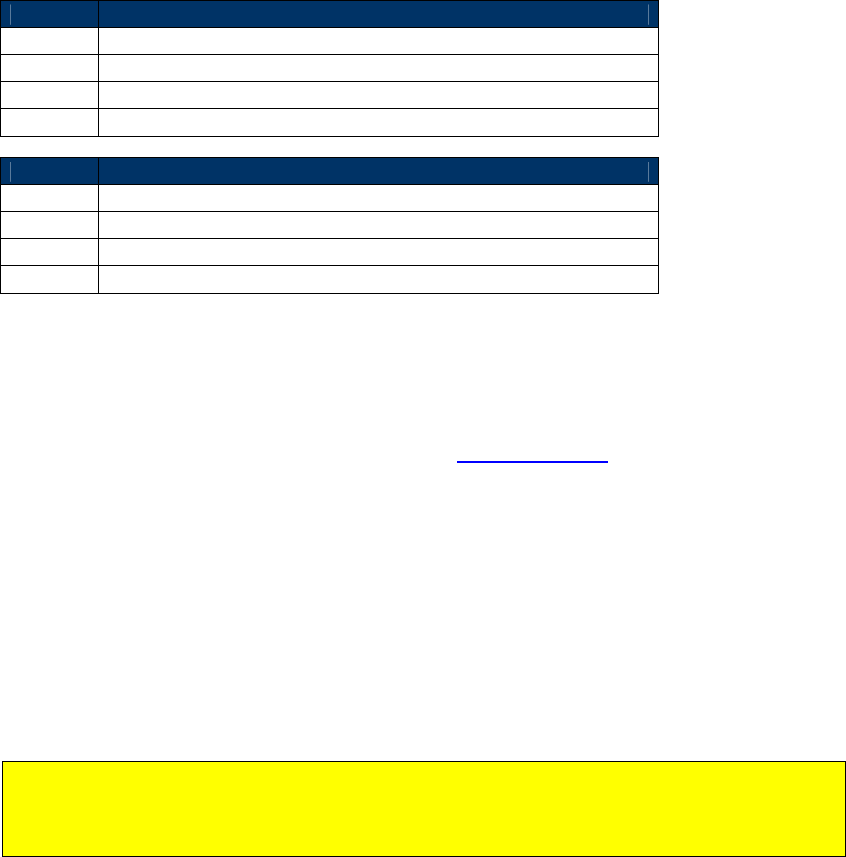
NEO Interface Developers Guide
114
Bit1 Bit0
Description
00
Don’t use transaction LED
01
Use transaction LED from ViVOpay reader
10
Use transaction LED from external source
11
Use transaction LED from both reader and external source
Bit3 Bit2
Description
00
Don’t use power LED
01
Use power LED from ViVOpay reader
10
Use power LED from external source
11
Use power LED from both reader and external source
The Date/Time can be configured to use internal or external Date/Time, depending on the
reader configuration. When the reader is configured to use internal time, the RTC (Real Time
Clock) chip is needed on the ViVOpay reader and the date and time from the RTC chip is used.
When the reader is configured to use external time, the terminal needs to set up the RTC inside
the ARM processor of the ViVOpay reader (using the Set Configuration command).
If configured to use the internal buzzer, the ViVOpay reader’s buzzer is used to indicate the
transaction progress. If configured to use external buzzer, an external buzzer is used and the
ViVOpay reader’s buzzer is not used.
If configured to use internal transaction LEDs, the ViVOpay reader’s transaction LEDs are used to
indicate the transaction progress. If configured to use external transaction LEDs, the transaction
LEDs on the terminal are used, and the reader’s transaction LEDs are not used.
If configured to use internal power LED, the ViVOpay reader’s power LED are used to indicate
the reader’s power state. If configured to use external power LED, the power LED on the
terminal are used.
Note: You can attempt to control the Power LED, but other UI behavior takes control, so
attempting to manipulate the Power LED in non-pass-through mode has no effect. This means
“Don’t use power LED” and “Use power LED from external source” won’t turn off the Power
LED.
Set Configuration Defaults Command (04-09)
This command provides an external method for resetting parameters in non-volatile memory
(NVM) to their default values.
When this serial command is received an NVM Initialization function is called and the display is
changed to show the message.
Initializing ….
Please Wait
Once initialization is complete the display is returned to the ready state message.

NEO Interface Developers Guide
115
Command Frame
Byte 0-9
Byte 10
Byte 11
Byte 12
Byte 13
Byte 14
Byte 15
Header Tag &
Protocol
Version
Command Sub-
Command
Data
Length
(MSB)
Data
Length
(LSB)
CRC (MSB) CRC (LSB)
ViVOtech2\0
04h
09h
00h
00h
87h
30h
Response Frame
Byte 0-9
Byte 10
Byte 11
Byte 12
Byte 13
Byte 14
Byte 15
Header Tag &
Protocol
Version
Command Status Code
Data
Length
(MSB)
Data
Length
(LSB)
CRC (MSB) CRC (LSB)
ViVOtech2\0
04
00h
00h
00h
AEh
16h
This command does not modify the following data objects:
Merchant Name and Location (tag 9F 4E)
Transaction Category code (tag 9F 53)
Terminal IFD Serial Number (tag FF F2)
Application Capability (tag FF F3)
Enable/Disable burst mode (tag FF F7)
LCD font size (tag FF F9)
LCD delay time (tag FF FA)
Poll mode (tag DF 89 1B)
Baud rate ( tag FE 02)
Boot up Message Enable (tag FE 03)
Serial Number (tag DF 89 1A)
UI Source Config (tag FE 05)
Analog parameters (tag FE FE)

NEO Interface Developers Guide
116
Set Configuration Defaults and Keep Encryption Key Command (04-0A)
This command provides an external method for resetting parameters in non-volatile memory
(NVM) to their default values.
When this serial command is received, the reader will erase eeporm and keep encryption keys.
When reader initialation is completed, the reader is rebooted.
Command Frame
Byte 0-9
Byte 10
Byte 11
Byte 12
Byte 13
Byte 14
Byte 15
Header Tag &
Protocol
Version
Command Sub-
Command
Data
Length
(MSB)
Data
Length
(LSB)
CRC (MSB) CRC (LSB)
ViVOtech2\0
04h
0Ah
00h
00h
F7h
46h
Response Frame
Byte 0-9
Byte 10
Byte 11
Byte 12
Byte 13
Byte 14
Byte 15
Header Tag &
Protocol
Version
Command Status Code
Data
Length
(MSB)
Data
Length
(LSB)
CRC (MSB) CRC (LSB)
ViVOtech2\0
04
00h
00h
00h
AEh
16h
This command does not modify the following data objects:
RKI-KEK
Data encryption Key
Encrypt type
Encrypt Status
Serial Number (tag DF 89 1A)
UI Source Config (tag FE 05)
Analog parameters (tag FE FE)
Baud rate ( tag FE 02)
Set Configuration (04-00)
Use this command to set or change the values of the specified Tag Length Value (TLV) data
objects in the reader. It can be used to set parameters for Auto Poll as well as Poll on Demand
Mode.
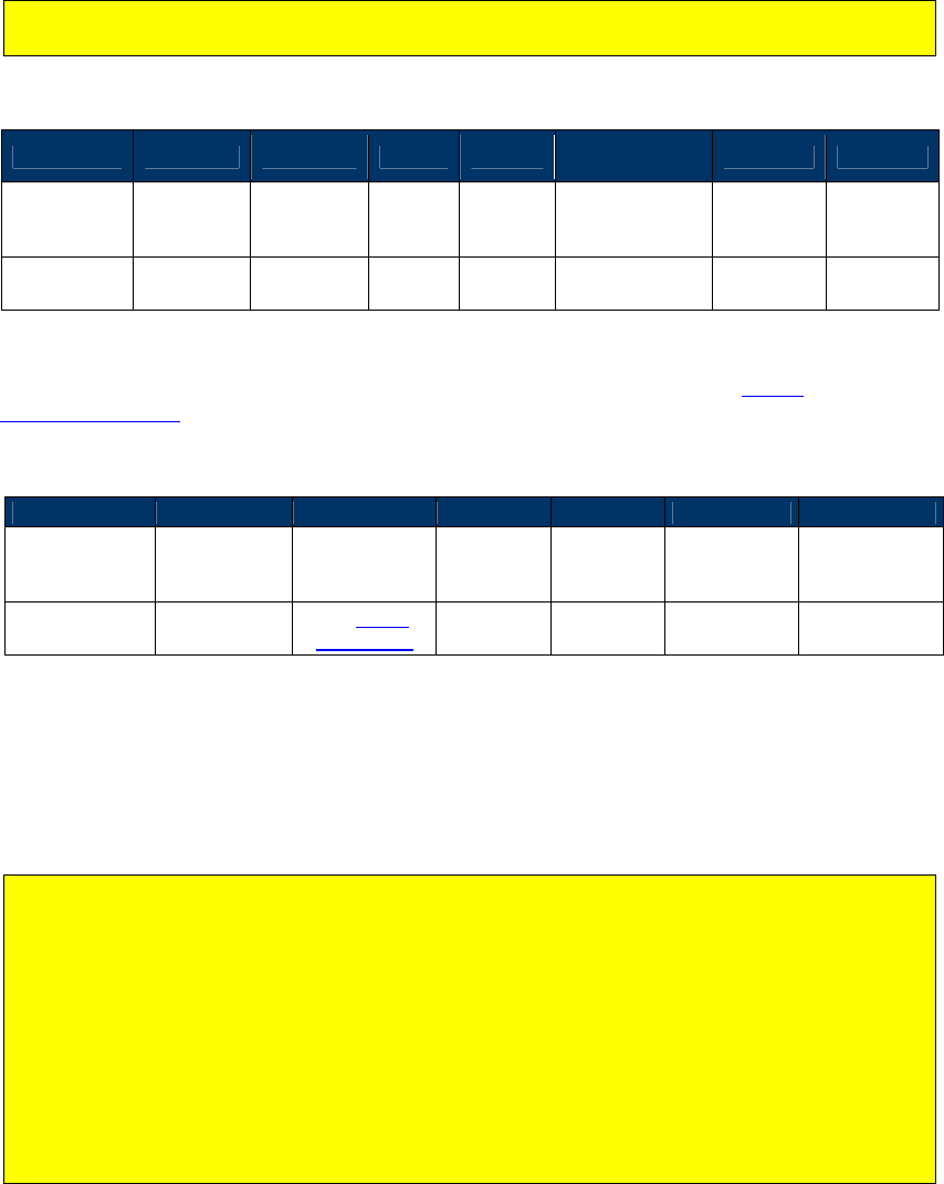
NEO Interface Developers Guide
117
When the reader receives this command, it extracts the TLV encoded parameters from the data
portion of the command and saves them to the default TLV Group in non-volatile memory. If a
TLV data object is incorrectly formatted, the reader stops processing the object. A single
command may contain more than one TLV data object.
The Set Configuration command is the only mechanism for setting the values of global
configuration parameters.
Command Frame
Byte 0-9 Byte 10 Byte 11 Byte 12
Byte 13
Byte 14 …
Byte 14+n-1 Byte 14+n
Byte 15+n
Header Tag
& Protocol
Version
Command
Sub-
Command
Data
Length
(MSB)
Data
Length
(LSB)
Data CRC
(LSB)
CRC
(MSB)
ViVOtech2\0
04h 00h
TLV Data
Objects
The TLV data objects that can be set using this command are defined in the Global
Configuration Tags table.
Response Frame
Byte 0-9
Byte 10
Byte 11
Byte 12
Byte 13
Byte 14
Byte 15
Header Tag &
Protocol
Version
Command Status Code
Data
Length
(MSB)
Data
Length
(LSB)
CRC (MSB) CRC (LSB)
ViVOtech2\0 04h
See Status
Code Table 00h 00h
Get Configuration (03-02)
Use this command to return the values of the TLV global data objects and default group data
objects (TLV Group 0) in the reader from the reader’s nonvolatile memory.
Note: If your reader supports Configurable Application Identifier (AIDs), the following
applies:
1. The Get Configuration command may be used to retrieve global configuration tags and
Group 0 configuration tags.
2. The Get Configuration command produces the same result as a Get Configurable Group
command for group 0 (default). Get Configuration cannot return TLVs from other TLV
Groups.
3. The Get Configuration command cannot return PayPass Group tags (because PayPass does
not use group 0).

NEO Interface Developers Guide
118
When the reader receives this command, it returns the current values for all the parameters
that can be set using the Set Configuration command. Each parameter is returned as a TLV data
object. Floor Limits for different AIDs are preceded by the TLV of the specific AID associated
with that object.
Command Frame
Byte 0-9
Byte 10
Byte 11
Byte 12
Byte 13
Byte 14
Byte 15
Header Tag &
Protocol
Version
Command Sub-
Command
Data
Length
(MSB)
Data
Length
(LSB)
CRC (LSB) CRC (MSB)
ViVOtech2\0
03h
02h
00h
00h
Response Frame
Byte 0-9 Byte 10 Byte 11 Byte 12
Byte 13
Byte 14 …
Byte 14+n-1 Byte 14+n
Byte 15+n
Header Tag
& Protocol
Version
Command
Status Code
Data
Length
(MSB)
Data
Length
(LSB)
Data CRC (MSB)
CRC (LSB)
ViVOtech2\0
03h
See Status
Code Table
TLV Data
Objects
Refer to the Global Configuration Tags and Group Configuration Tags for definitions of tags that
can be returned in this command.
Get Version Protocol 2 (29-00)
Get the ViVOpay Firmware Version Number from the ViVOpay reader. The reader returns a
Response Frame containing the ViVOpay firmware version information.
Command Frame
Byte 0-9
Byte 10
Byte 11
Byte 12
Byte 13
Byte 14
Byte 15
Header Tag &
Protocol
Version
Command Sub-
Command
Data
Length
(MSB)
Data
Length
(LSB)
CRC (LSB) CRC (MSB)
ViVOtech2\0
29h
00h
00h
00h
Response Frame
Byte 0-9 Byte 10 Byte 11 Byte 12
Byte 13
Byte 14 …
Byte 14+n-1
Byte 14+n
Byte 15+n
Header Tag
& Protocol
Version
Command
Status Code
Data
Length
(MSB)
Data
Length
(LSB)
Data CRC (MSB)
CRC
(LSB)
ViVOtech2\0
29h
See Status
Code Table
00h
String
length Version string
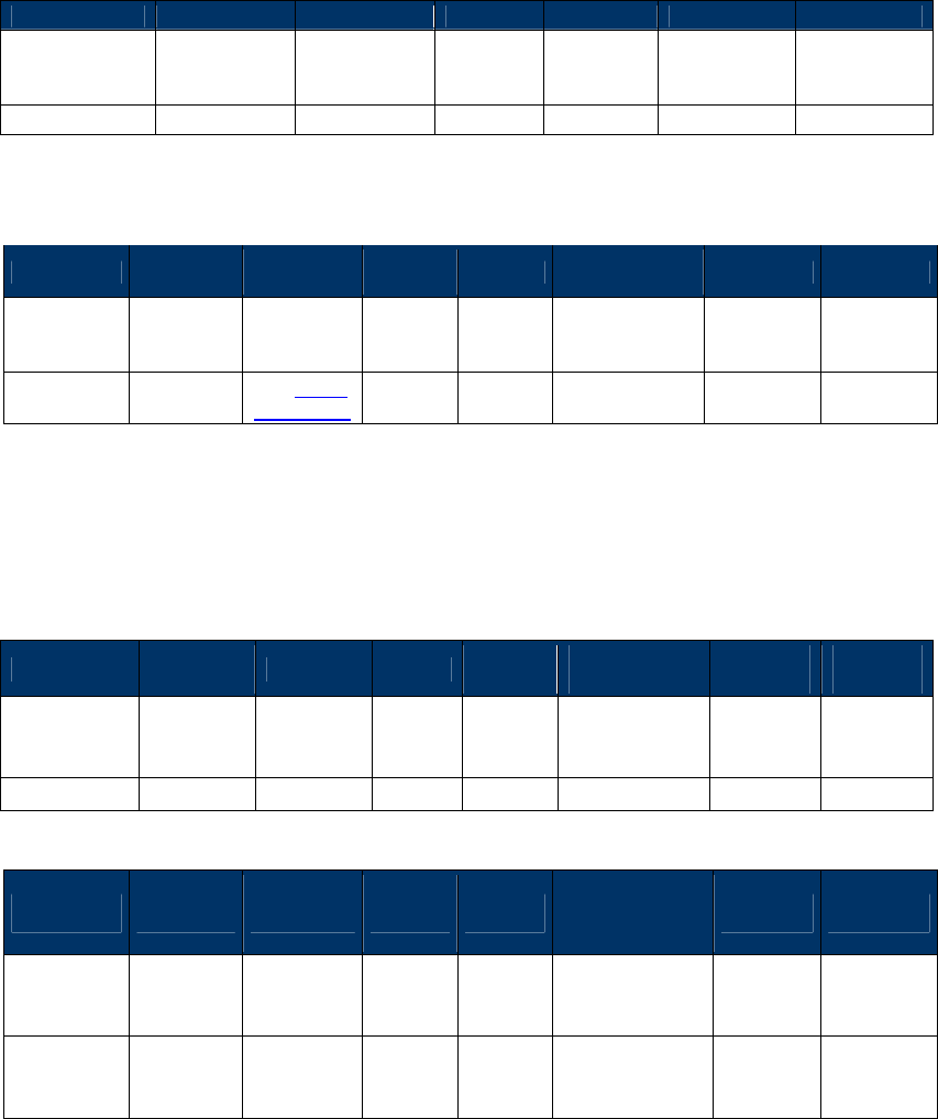
NEO Interface Developers Guide
119
Get USB Boot Loader Version (29-04)
Get the version of the USB Boot Loader.
Command Frame
Byte 0-9
Byte 10
Byte 11
Byte 12
Byte 13
Byte 14
Byte 15
Header Tag &
Protocol
Version
Command Sub-
Command
Data
Length
(MSB)
Data
Length
(LSB)
CRC (LSB) CRC (MSB)
ViVOtech2\0
29h
04h
00h
00h
Response Frame
Byte 0-9 Byte 10 Byte 11 Byte 12
Byte 13
Byte 14 …
Byte 14+n-1 Byte 14+n
Byte 15+n
Header Tag
& Protocol
Version
Command
Status Code
Data
Length
(MSB)
Data
Length
(LSB)
Data CRC (MSB)
CRC
(LSB)
ViVOtech2\0
29h
See Status
Code Table
00h
String
length
Version string
Get Contact EMV L2 Kernel Version (29-06)
This function can get contact EMV L2 kernel library major version.
Command Frame
Byte 0-9 Byte 10 Byte 11 Byte 12
Byte 13
Byte 14 …
Byte 14+n-1
Byte
14+n
Byte
15+n
Header Tag
& Protocol
Version
Command
Sub-
Command
Data
Length
(MSB)
Data
Length
(LSB)
Data CRC
(LSB)
CRC
(MSB)
ViVOtech2\0
29h 06h 00h 00h
Response Frame
Byte 0-9 Byte 10 Byte 11 Byte 12
Byte 13
Byte 14 …
Byte 14+n-1 Byte 14+n
Byte 15+n
Header Tag
& Protocol
Version
Command
Status Code
Data
Length
(MSB)
Data
Length
(LSB)
Data CRC
(MSB)
CRC
(LSB)
ViVOtech2\
0 29h
See
Status
Code
Table
See Response
Frame
Response Frame Example: “EMV Common L2 V1.10”

NEO Interface Developers Guide
120
Note:VP4880C not supported.
Get Contact EMV L2 Kernel Version Detail (29-07)
This function can get contact EMV L2 kernel library major and minor version.
Command Frame
Byte 0-9 Byte 10 Byte 11 Byte 12
Byte 13
Byte 14 …
Byte 14+n-1
Byte
14+n
Byte
15+n
Header Tag
& Protocol
Version
Command
Sub-
Command
Data
Length
(MSB)
Data
Length
(LSB)
Data CRC
(LSB)
CRC
(MSB)
ViVOtech2\0
29h 07h 00h 00h
Response Frame
Byte 0-9 Byte 10 Byte 11 Byte 12
Byte 13
Byte 14 …
Byte 14+n-1 Byte 14+n
Byte 15+n
Header Tag
& Protocol
Version
Command
Status Code
Data
Length
(MSB)
Data
Length
(LSB)
Data CRC
(MSB)
CRC
(LSB)
ViVOtech2\
0 29h See Status
Code Table
See Response
Frame
Response Frame Example: “EMV Common L2 V1.10.037”
Note:VP4880C not supported.
Get Contact EMV L2 Kernel Checksum (29-08)
This function can get contact EMV L2 kernel library checksum. The checksum uses SHA-1.
Command Frame
Byte 0-9 Byte 10 Byte 11 Byte 12
Byte 13
Byte 14 …
Byte 14+n-1
Byte
14+n
Byte
15+n
Header Tag
& Protocol
Version
Command
Sub-
Command
Data
Length
(MSB)
Data
Length
(LSB)
Data CRC
(LSB)
CRC
(MSB)
ViVOtech2\0
29h 08h 00h 00h

NEO Interface Developers Guide
121
Response Frame
Byte 0-9 Byte 10 Byte 11 Byte 12
Byte 13
Byte 14 …
Byte 14+n-1 Byte 14+n
Byte 15+n
Header Tag
& Protocol
Version
Command
Status Code
Data
Length
(MSB)
Data
Length
(LSB)
Data CRC
(MSB)
CRC
(LSB)
ViVOtech2\
0 29h
See
Status
Code
Table
See Response
Frame
Response Frame Example: “8D 93 95 C5 88 F2 DE C9 AE 9D C8 BB 7B 98 41 A3 52 57 11 C6”
Note:VP4880C not supported.
Get Contact EMV L2 Terminal Configuration Checksum (29-09)
This function can get contact EMV L2 terminal data checksum. (Calculate tags 9F33, 9F35, 9F40,
DF11, DF26, DF27, DFEE1E). The checksum uses SHA-1.
Command Frame
Byte 0-9 Byte 10 Byte 11 Byte 12
Byte 13
Byte 14 …
Byte 14+n-1
Byte
14+n
Byte
15+n
Header Tag
& Protocol
Version
Command
Sub-
Command
Data
Length
(MSB)
Data
Length
(LSB)
Data CRC
(LSB)
CRC
(MSB)
ViVOtech2\0
29h 09h 00h 00h
Response Frame
Byte 0-9 Byte 10 Byte 11 Byte 12
Byte 13
Byte 14 …
Byte 14+n-1 Byte 14+n
Byte 15+n
Header Tag
& Protocol
Version
Command
Status Code
Data
Length
(MSB)
Data
Length
(LSB)
Data CRC
(MSB)
CRC
(LSB)
ViVOtech2\
0 29h
See
Status
Code
Table
See Response
Frame
Response Frame Example: “B4 30 CE B9 FE 85 8B 00 B8 B2 7D 6F 56 EF 40 D4 2F 0E AF 8A”
Note:VP4880C not supported.

NEO Interface Developers Guide
122
Get UID of MCU (29-17)
This function can get the 16 byte UID of MCU.
Command Frame
Byte 0-9 Byte 10 Byte 11 Byte 12
Byte 13
Byte 14 …
Byte 14+n-1
Byte
14+n
Byte
15+n
Header Tag
& Protocol
Version
Command
Sub-
Command
Data
Length
(MSB)
Data
Length
(LSB)
Data CRC
(LSB)
CRC
(MSB)
ViVOtech2\0
29h 17h 00h 00h
Response Frame
Byte 0-9 Byte 10 Byte 11 Byte 12
Byte 13
Byte 14 …
Byte 14+n-1 Byte 14+n
Byte 15+n
Header Tag
& Protocol
Version
Command
Status Code
Data
Length
(MSB)
Data
Length
(LSB)
Data CRC
(MSB)
CRC
(LSB)
ViVOtech2\
0 29h
See
Status
Code
Table
See Response
Frame
Response Frame Data Example: “00 00 1D 00 61 26 1C 6B 75 31 45 4E 05 00 01 10”
Set Baud Rate (30-01)
This command instructs the reader to change its baud rate to the specified value. If the
Command Frame is valid and the ViVOpay reader supports the specified baud rate, it returns an
OK response and then switches to the specified baud rate. If the Command Frame is not valid,
or an invalid baud rate parameter is specified then the reader returns an error Response Frame.
The new baud rate is retained over power cycles.
Command Frame
Byte 0-9
Byte 10
Byte 11
Byte 12
Byte 13
Byte 14
Byte 14+n
Byte 15+n
Header Tag
& Protocol
Version
Command
Sub-
Command
Data
Length
(MSB)
Data
Length
(LSB)
Data CRC (LSB)
CRC (MSB)
ViVOtech2\0
30h 01h 00h 01h
Baud Rate
Code
Baud Rate Code Baud Rate
01h
9600 baud
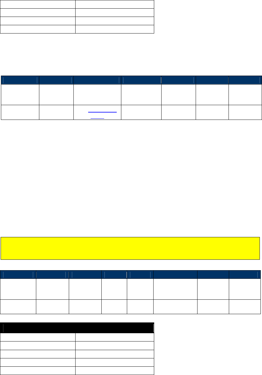
NEO Interface Developers Guide
123
02h
19200 baud
03h
38400 baud
04h
57600 baud
05h
115200 baud
Important: All other values for Baud Rate Code are invalid and should not be accepted by
reader.
Response Frame
Byte 0-9
Byte 10
Byte 11
Byte 12
Byte 13
Byte 14
Byte 15
Header Tag &
Protocol
Version
Command
Status Code Data Length
(MSB)
Data Length
(LSB) CRC (MSB)
CRC (LSB)
ViVOtech2\0
30h
See Status Code
Table 00h 00h
The reader switches baud rate only if the Response Frame contains an OK Status Code. No data
is returned in the response.
Set Temporary Baud Rate (30-02)
This command instructs the reader to change its baud rate to the specified value temporarily.
After power up, the baud rate will return to the previous value. If the Command Frame is
valid and the ViVOpay reader supports the specified baud rate, it returns an OK response and
then switches to the specified baud rate. If the Command Frame is not valid, or an invalid baud
rate parameter is specified then the reader returns an error Response Frame.
Note: If the new baud rate is set by sending 30-02 command, then after power up, the baud
rate will return to the previous value. If the new baud rate is set by sending 30-01 command,
then after power up, the baud rate will still be the new value.
Command Frame
Byte 0-9
Byte 10
Byte 11
Byte 12
Byte 13
Byte 14
Byte 14+n
Byte 15+n
Header Tag
& Protocol
Version
Command
Sub-
Command
Data
Length
(MSB)
Data
Length
(LSB)
Data CRC (LSB)
CRC (MSB)
ViVOtech2\0
30h 02h 00h 01h
Baud Rate
Code
Baud Rate Code
Baud Rate
01h
9600 baud
02h
19200 baud
03h
38400 baud
04h
57600 baud
05h
115200 baud

NEO Interface Developers Guide
124
Important: All other values for Baud Rate Code are invalid and should not be accepted by
reader.
Response Frame
Byte 0-9
Byte 10
Byte 11
Byte 12
Byte 13
Byte 14
Byte 15
Header Tag &
Protocol
Version
Command
Status Code Data Length
(MSB)
Data Length
(LSB) CRC (MSB)
CRC (LSB)
ViVOtech2\0
30h
See Status Code
Table 00h 00h
The reader switches baud rate only if the Response Frame contains an OK Status Code. No data
is returned in the response.
Set Baud Rate and Audio Level (30-03) – UniPay 1.5 & UniPay III
This command instructs the reader to change its baud rate to the specified value. If the
Command Frame is valid and the ViVOpay reader supports the specified baud rate, it returns an
OK response and then switches to the specified baud rate. If the Command Frame is not valid,
or an invalid baud rate parameter is specified then the reader returns an error Response Frame.
The new baud rate is retained over power cycles.
Command Frame
Byte 0-9
Byte 10
Byte 11
Byte 12
Byte 13
Byte 14
Byte 14+n
Byte 15+n
Header Tag
& Protocol
Version
Command
Sub-
Command
Data
Length
(MSB)
Data
Length
(LSB)
Data CRC (LSB)
CRC (MSB)
ViVOtech2\0
30h 03h 00h 01h
Baud Rate
Code
Baud Rate Code Baud Rate Note
01h
9600 baud
Send data 0x55 …. 0x55 0x66 before response
02h 9600 baud
Do not send data 0x55 …. 0x55 0x66 before
response
03h
2400 baud and Level minimum
This value is used for android SDK only
04h
4800 baud and Level minimum
This value is used for android SDK only
05h
9600 baud and Level minimum
This value is used for android SDK only
33h
2400 baud and Level 1
This value is used for android SDK only
34h
4800 baud and Level 1
This value is used for android SDK only
35h
9600 baud and Level 1
This value is used for android SDK only
The baud rate code 03h, 04h, 05h, 33h, 34h and 35h only adjust baud rate and audio level when
reader sends response to Terminal, and sets baud rate and level to 9600 and L1 after
transmission is finished.
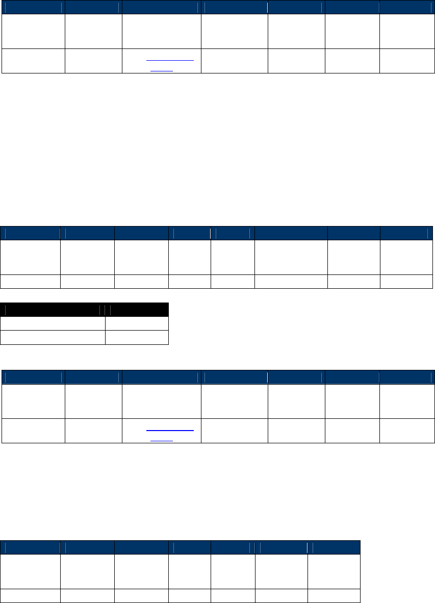
NEO Interface Developers Guide
125
Important: All other values for Baud Rate Code are invalid and should not be accepted by
reader.
Response Frame
Byte 0-9
Byte 10
Byte 11
Byte 12
Byte 13
Byte 14
Byte 15
Header Tag &
Protocol
Version
Command
Status Code Data Length
(MSB)
Data Length
(LSB) CRC (MSB)
CRC (LSB)
ViVOtech2\0
30h
See Status Code
Table 00h 00h
The reader switches baud rate only if the Response Frame contains an OK Status Code. No data
is returned in the response.
Set Cable Type (32-02)
Kiosk III has two type of cable, so called "long cable" and "short cable". Kiosk III is calibrated for
long cable and short cable, and saves both set of parameters for antenna checking. User can set
the cable type accordingly.
If the cable type is not set, reader will consider the cable type as long cable by default.
Command Frame
Byte 0-9
Byte 10
Byte 11
Byte 12
Byte 13
Byte 14
Byte 15
Byte 16
Header Tag
& Protocol
Version
Command
Sub-
Command
Data
Length
(MSB)
Data
Length
(LSB)
Data CRC (LSB)
CRC (MSB)
ViVOtech2\0
32h
02h
00h
01h
Cable Type
Cable Type
Value
Long cable (default)
0
Short cable
1
Response Frame
Byte 0-9
Byte 10
Byte 11
Byte 12
Byte 13
Byte 14
Byte 15
Header Tag &
Protocol
Version
Command
Status Code Data Length
(MSB)
Data Length
(LSB) CRC (MSB)
CRC (LSB)
ViVOtech2\0
32h
See Status Code
Table
00h 00h
Get Cable Type (32-01)
This command is used to get the cable type which is set. If the cable type is not set, reader will
consider the cable type as long cab le by default.
Command Frame
Byte 0-9
Byte 10
Byte 11
Byte 12
Byte 13
Byte 14
Byte 15
Header Tag
& Protocol
Version
Command
Sub-
Command
Data
Length
(MSB)
Data
Length
(LSB)
CRC (LSB)
CRC (MSB)
ViVOtech2\0
32h
01h
00h
00h
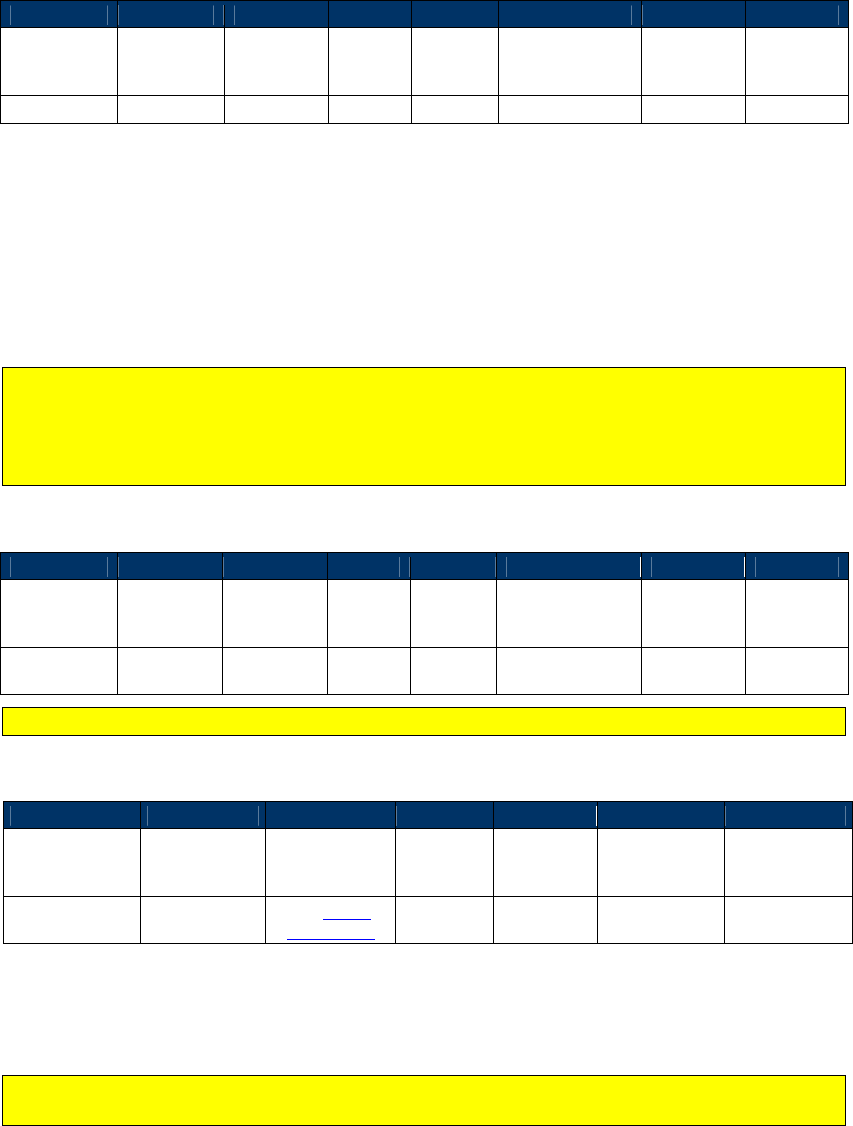
NEO Interface Developers Guide
126
Response Frame
Byte 0-9
Byte 10
Byte 11
Byte 12
Byte 13
Byte 14
Byte 15
Byte 16
Header Tag
& Protocol
Version
Command
Status
Code
Data
Length
(MSB)
Data
Length
(LSB)
Data CRC (LSB)
CRC (MSB)
ViVOtech2\0
32h
00h
00h
01h
Cable Type
Set Serial Number (12-02)
This command instructs the ViVOpay to store the 15-digit serial number in its non-volatile
memory. If a serial number has already been set in the reader then this command fails with a
Command Not Allowed error status. If the Command Frame is not valid, or the length is not 15
bytes then ViVOpay returns an error Response Frame.
Note: The reader serial number can only be set once. For Kiosk III, the coding of serial
number must follow ID Tech Product Serial Number Requirement. If the input serial number
does not satisfied by ID Tech Product Serial Number Requirement, reader will reject this
command and respond error. For detailed information, refer to "WI 7.5.1-8 ID TECH Product
Serial Number Requirements"
Command Frame
Byte 0-9
Byte 10
Byte 11
Byte 12
Byte 13
Byte 14
Byte 14+n
Byte 15+n
Header Tag
& Protocol
Version
Command
Sub-
Command
Data
Length
(MSB)
Data
Length
(LSB)
Data CRC (LSB)
CRC (MSB)
ViVOtech2\
0
12h 02h 00h 0Fh
15 digit Serial
Number
Note: For the 15 digit Serial Number in Kiosk III, only the first 10 bytes are valid.
Response Frame
Byte 0-9
Byte 10
Byte 11
Byte 12
Byte 13
Byte 14
Byte 15
Header Tag &
Protocol
Version
Command Status Code
Data
Length
(MSB)
Data
Length
(LSB)
CRC (MSB) CRC (LSB)
ViVOtech2\0 12h
See Status
Code Table 00h 00h
Get Serial Number (12-01)
Note: This command can only be used after the reader has received a Set Serial Number
command.
This command instructs the ViVOpay to return the 15-digit serial number stored in its non-
volatile memory. If a serial number has not been set in the reader then this command fails with
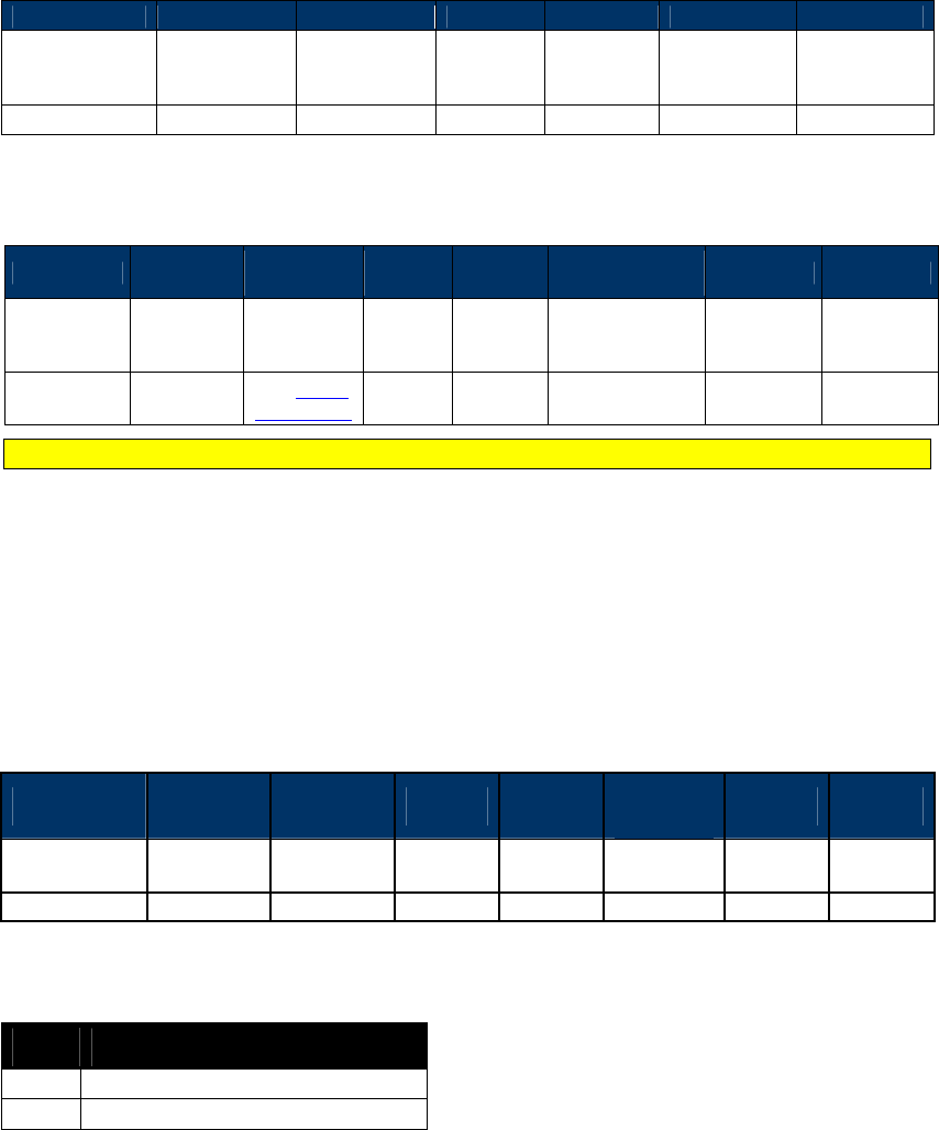
NEO Interface Developers Guide
127
a Command Not Allowed error status. If the Command Frame is not valid then ViVOpay returns
an error Response Frame.
Command Frame
Byte 0-9
Byte 10
Byte 11
Byte 12
Byte 13
Byte 14
Byte 15
Header Tag &
Protocol
Version
Command Sub-
Command
Data
Length
(MSB)
Data
Length
(LSB)
CRC (LSB) CRC (MSB)
ViVOtech2\0
12h
01h
00h
00h
Response Frame
Byte 0-9 Byte 10 Byte 11 Byte 12
Byte 13
Byte 14 … Byte
14+n-1 Byte 14+n
Byte 15+n
Header Tag
& Protocol
Version
Command
Status Code
Data
Length
(MSB)
Data
Length
(LSB)
Data CRC (MSB)
CRC
(LSB)
ViVOtech2\0
12h
See Status
Code Table
00h 0Fh
15-digit Serial
Number
Note: For the 15 digit Serial Number in Kiosk III, only the first 10 bytes are valid.
Bootup Notification Command (14-01)
The ViVOpay firmware has the ability to spontaneously transmit its version information over the
serial line during bootup. In this way the reader can notify the POS that it is ready to
communicate when the bootup process has finished.
This feature can be toggled on or off using of the Bootup Notification command.
Command Frame
Byte 0-9 Byte 10 Byte 11 Byte 12 Byte 13 Byte 14-
Byte 18 Byte 19 Byte 20
Header Tag &
Protocol Command Sub
Command
Length
MSB
Length
LSB
Data
1 Bytes
CRC
(LSB)
CRC
(MSB)
ViVOtech2/0 14h 01h 00h 01h See below Varies Varies
This command contains a single 1-byte argument.
Byte Description
00h
Bootup Notification is disabled.
01h
Bootup Notification is enabled.
If Bootup Notification is enabled, the firmware transmits its Firmware Version string one time at
the end of bootup.
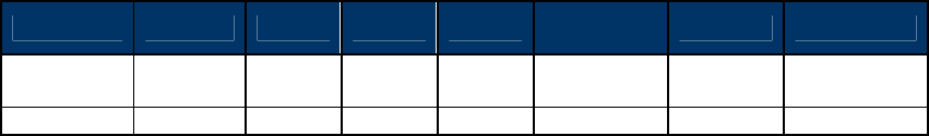
NEO Interface Developers Guide
128
For example, if a Vendi reader were enabled, it would begin to transmit its string, in this case,
“Vendi V1.00” each time it was restarted.
Response Frame
Byte 0-9 Byte 10 Byte 11
Byte 12
Byte 13
Byte 14-
Byte 14+n-1
Byte 14+n
Byte 14+n+1
Header Tag
& Protocol
Command
Status Length
MSB
Length
LSB
Data
1 Bytes
CRC
(LSB)
CRC
(MSB)
ViVOtech2/0
14h
Varies
00h
00h
NA
Varies
Varies
Configurable AID and Group Commands
Set Configurable AID (04-02)
This command creates or selects an AID for configuration or deletion. There are eight TLVs that
can be included in this command, some of which are mandatory.
TLV Group Number – This number refers to the group that has been created containing all of the
characteristics desired for this AID. Setting and configuring the TLV Group Number is explained
below. The TLV Group Number must be configured first. If an AID is communicated referring to a
non-existing group, that AID is rejected.
Registered Application Provider Identifier (RID) – The parameter is optional. If it is provided, this
number is used to reference the CA Public Key payment system. If it is not provided the first
five bytes of the AID are used.
For System AIDs:
Must always include the TLV Group Number TLV as the FIRST TLV in the message.
Must always include the AID TLV as the SECOND TLV in the message.
Must never include the Application Flow TLV in the message
Must never include the RID TLV in the message
The FOUR remaining TLVs are all optional.
There are System AIDs in the reader. These can be disabled but cannot be deleted.
For User AIDs:
Must always include the TLV Group Number TLV as the FIRST TLV in the message.
Must always include the AID TLV as the SECOND TLV in the message.
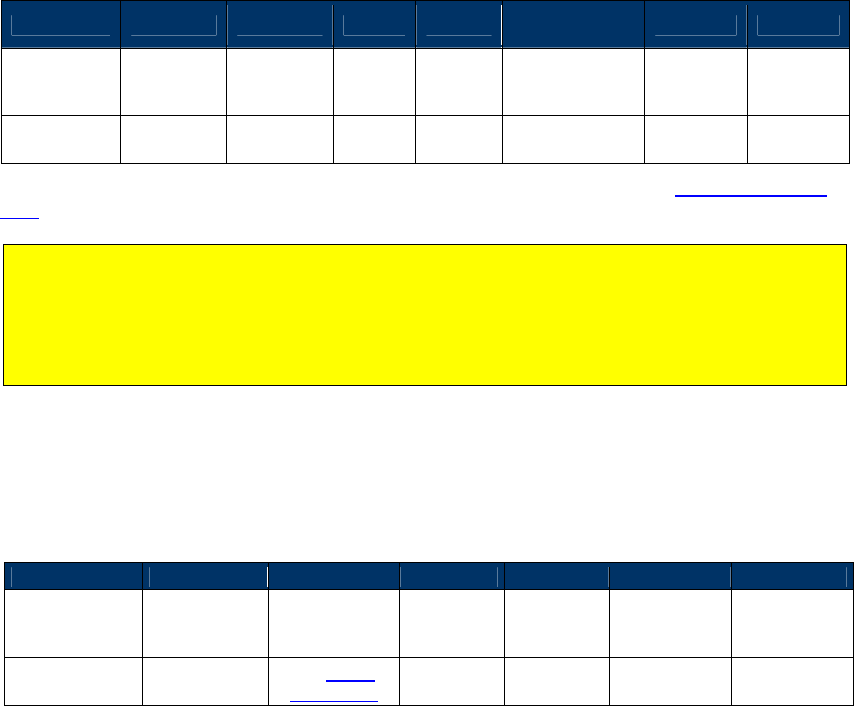
NEO Interface Developers Guide
129
Must always include the Application Flow TLV in the message
The FIVE remaining TLVs are all optional.
The DISABLE AID tag is ignored if included in a USER AID.
There are eight User AIDs in the system. These can be added (set) or deleted at the user’s
discretion.
No User AID can have the same exact AID as a System AID.
In addition to the above requirements:
All AIDs must reference a TLV Group (in the TLV Group Number TLV) that already exists
Any AID with a Partial Select TLV must also include the Max AID Length TLV
Command Frame
Byte 0-9 Byte 10 Byte 11 Byte 12
Byte 13
Byte 14 …
Byte 14+n-1 Byte 14+n
Byte 15+n
Header Tag
& Protocol
Version
Command
Sub-
Command
Data
Length
(MSB)
Data
Length
(LSB)
Data CRC (LSB)
CRC (MSB)
ViVOtech2\0
04h 02h
TLV Data
Objects
The TLV Data Objects that can be set using this command are defined in the AID Configuration
Tags.
To set Configurable AID tags, the Application Identifier (9F06) and Group Number (FFE4) are
mandatory tags.
Note: At present, the preferred means of disabling a System AID is NOT to include the FFE6
TLV. Instead, just issue a Delete AID command to for particular AID. This deletes a User AID
OR disables a System AID.
If a Set Configurable AID command is sent without an FFE6 TLV, the reader enables the AID if it
is not already enabled.
Finally, a Set AID command used for a User AID can include a FFE6 Disable AID Tag, but it is
ignored. This tag is only used to set System AID.
Response Frame
Byte 0-9
Byte 10
Byte 11
Byte 12
Byte 13
Byte 14
Byte 15
Header Tag &
Protocol
Version
Command Status Code
Data
Length
(MSB)
Data
Length
(LSB)
CRC (MSB) CRC (LSB)
ViVOtech2\0 04h
See Status
Code Table
00h 00h
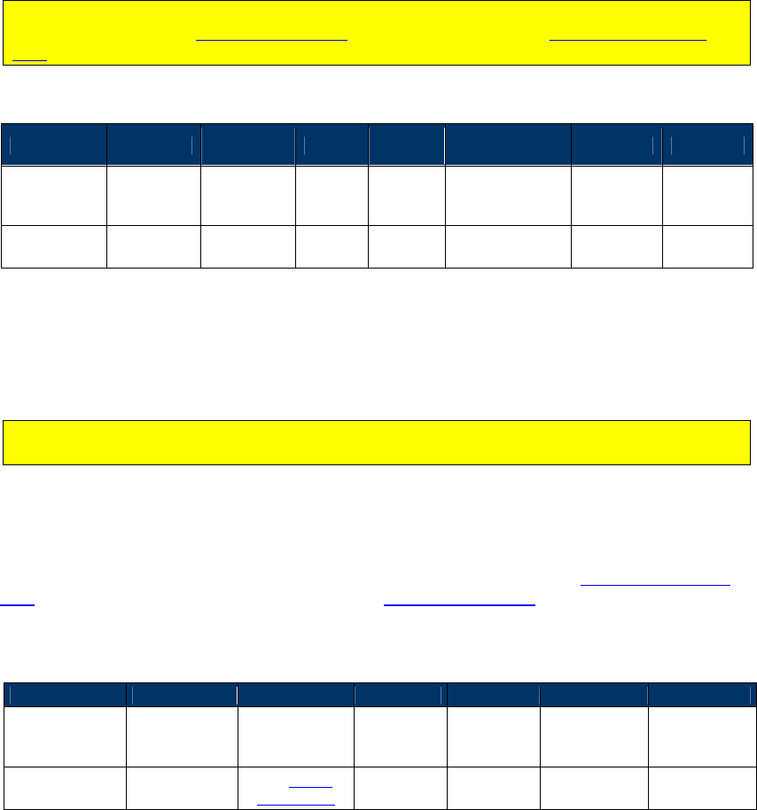
NEO Interface Developers Guide
130
Set Configurable Group (04-03)
This command creates or modifies a TLV Group. You configure a specific TLV Group by passing
the TLVs with the desired functionality and a unique TLV Group Number to the reader. The TLVs
that can be associated with a TLV Group are listed below. A TLV Group Number and at least one
other TLV is required. The reader uses TLVs in the default TLV Group 0 for any TLVs not defined
in the user-defined TLV Group.
For M/Chip 3.0, Group 0 is not used. If you are configuring a group for M/Chip PayPass, then
you should refer to the PayPass Group Tags. Otherwise, refer to the Group Configuration
Tags.
Command Frame
Byte 0-9 Byte 10 Byte 11 Byte 12
Byte 13
Byte 14 …
Byte 14+n-1 Byte 14+n
Byte 15+n
Header Tag
& Protocol
Version
Command
Sub-
Command
Data
Length
(MSB)
Data
Length
(LSB)
Data CRC (LSB)
CRC (MSB)
ViVOtech2\0
04h 03h
TLV Data
Objects
If you are changing TLVs in Group 0 (the Default Group) the reader retains and uses the old
values of any TLVs not included in the Set Configurable Group command. If you are changing any
other Group, the reader discards existing TLVs not in the current Set Configurable Group
command.
The implication of the statement above is that if you are configuring a group for PayPass, you
must configure all of the necessary tags, as they will not default to Group 0 tags.
To set the TDOL TLV, simply pass on the desired values in the TLV. To disable the default TDOL,
send a TDOL TLV with Length set to zero and no Value field included. This instructs the reader
to delete any existing TDOL list for this group.
The TLV Data Objects that can be set using this command are given in the Configurable Group
Tags Table (for non- PayPass applications) or the PayPass Group Tags.
Response Frame
Byte 0-9
Byte 10
Byte 11
Byte 12
Byte 13
Byte 14
Byte 15
Header Tag &
Protocol
Version
Command Status Code
Data
Length
(MSB)
Data
Length
(LSB)
CRC (MSB) CRC (LSB)
ViVOtech2\0 04h
See Status
Code Table 00h 00h
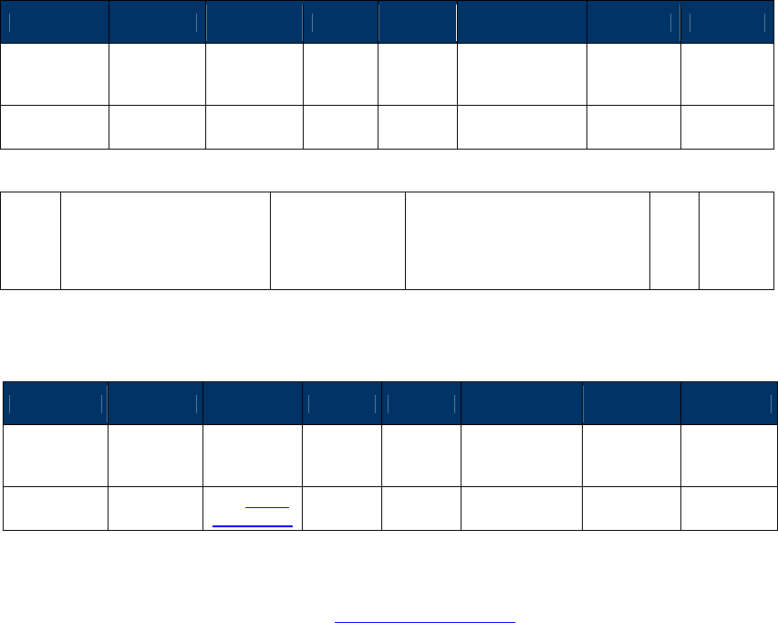
NEO Interface Developers Guide
131
Get Configurable AID (03-04)
This command returns the configurable (User) AID parameters. The user MUST send an AID TLV
in the command, as the first TLV in the command. The reader then returns all tags associated
with that User AID in the response.
Command Frame
Byte 0-9 Byte 10 Byte 11 Byte 12
Byte 13
Byte 14 …
Byte 14+n-1 Byte 14+n
Byte 15+n
Header Tag
& Protocol
Version
Command
Sub-
Command
Data
Length
(MSB)
Data
Length
(LSB)
Data CRC (LSB)
CRC (MSB)
ViVOtech2\0
03h 04h
TLV Data
Objects
The command MUST include the TLV below. The command should NOT include any other TLV.
9F06 Application Identifier
(AID) – terminal MANDATORY
Identifies the application as
described in ISO/IEC 7816-5.
Note: This is the ONLY TLV in
this command.
b 5 – 16
Response Frame
Byte 0-9 Byte 10 Byte 11 Byte 12
Byte 13
Byte 14 …
Byte 14+n-1
Byte 14+n
Byte 15+n
Header Tag
& Protocol
Version
Command
Status Code
Data
Length
(MSB)
Data
Length
(LSB)
Data CRC (MSB)
CRC (LSB)
ViVOtech2\0
03h
See Status
Code Table
TLV Data
Objects
The optional Data Objects encoded as TLV that is returned in the data section of the Response
Frame are the same as those listed in the AID Configuration Tags. The reader returns ALL TLV
associated with this AID in its response.
If an AID is requested and the reader fails to find it in its database, the reader returns the AID
TLV itself and NO additional arguments. This indicates that the command was correct with the
proper argument, but there was no match in the reader’s database. The reader does NOT
indicate an error situation.
If the user requests a System AID that is currently disabled, the reader returns the AID TLVs, but
appends the FFE6 TLV, showing that the AID is currently disabled.
Get Configurable Group (03-06)
Use this command to return all TLVs associated the specified Configurable Group. A configurable
Group Tag must be included as the ONLY TLV in this command. The response should contain all
of the Tags associated with this configurable Group.
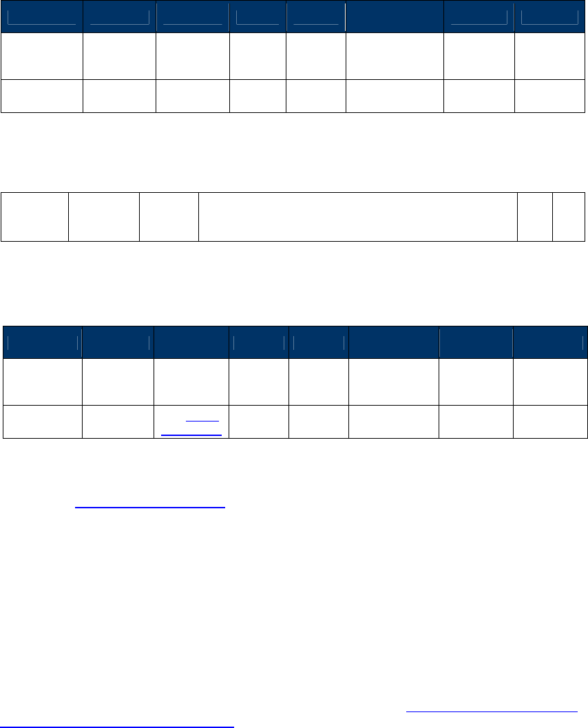
NEO Interface Developers Guide
132
Command Frame
Byte 0-9 Byte 10 Byte 11 Byte 12
Byte 13
Byte 14 …
Byte 14+n-1
Byte 14+n
Byte 15+n
Header Tag
& Protocol
Version
Command
Sub-
Command
Data
Length
(MSB)
Data
Length
(LSB)
Data CRC (LSB)
CRC (MSB)
ViVOtech2\0
03h 06h
TLV Data
Objects
The following TLV MUST be encoded in the command, it is the ONLY tag included in the
command.
FFE4[1] Group
Number MAND
The group that contains the properties for this AID
Note: This must be the ONLY TLV in Data Field.
n2
1
[1]
These objects use proprietary tags. The use of these tags should be restricted to the serial interface. Once the reader
has received these values and saved them in memory, it should dispose of the tags (and not keep them associated with
these two values).
Response Frame
Byte 0-9 Byte 10 Byte 11 Byte 12
Byte 13
Byte 14 …
Byte 14+n-1
Byte 14+n
Byte 15+n
Header Tag
& Protocol
Version
Command
Status Code
Data
Length
(MSB)
Data
Length
(LSB)
Data CRC (MSB)
CRC (LSB)
ViVOtech2\0
03h
See Status
Code Table
TLV Data
Objects
The Data Objects encoded as TLV that is returned in the data section of the Response Frame are
given in the Group TLV Objects Table.
If the user requests a Group that is illegal, an error response is sent back.
If the user requests a valid Group number but the Group does NOT exist, then the reader returns
the regular response but only includes the Group Number TLV (no other TLV is included). This
signifies that the user has requested a valid number but no Group has been assigned to it.
Note: For a PayPass group, if a TLV data item is not present in the Group then it will not be
present in the data returned by this command. However, this does not mean that there is no
value for this particular TLV in order to perform a transaction. It is possible that the PayPass
Kernel may have a hard-coded value for this TLV which will be used in a transaction if the TLV is
not present in the Group or in Activate Transaction data. The data items for which the PayPass
kernel has hard-coded default values are given in in the section on PayPass Group Configuration
TLVs with Hard-Coded Values in Kernel.
Delete Configurable AID (04-04)
This command deletes a configurable AID. It is MANDATORY to include the AID TLV of the AID to
be removed. No other TLVs should be included.
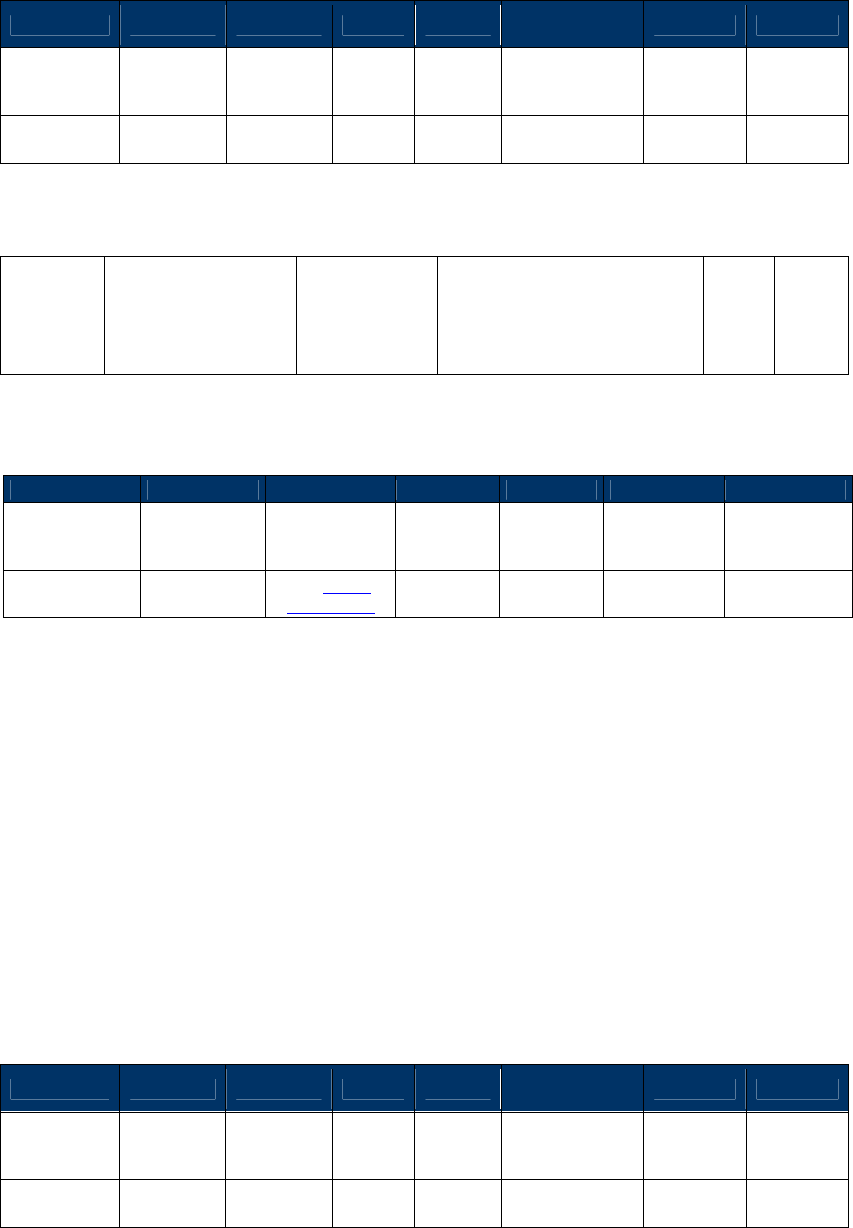
NEO Interface Developers Guide
133
Command Frame
Byte 0-9 Byte 10 Byte 11 Byte 12
Byte 13
Byte 14 …
Byte 14+n-1
Byte 14+n
Byte 15+n
Header Tag
& Protocol
Version
Command
Sub-
Command
Data
Length
(MSB)
Data
Length
(LSB)
Data CRC (LSB)
CRC (MSB)
ViVOtech2\0
04h 04h
TLV Data
Objects
The Data Object encoded as TLV that can be set using this command is below.
9F06 Application Identifier
(AID) – terminal MANDATORY
Identifies the application as
described in ISO/IEC 7816-5.
Note: This is the ONLY TLV in
this command.
b 5 – 16
Response Frame
Byte 0-9
Byte 10
Byte 11
Byte 12
Byte 13
Byte 14
Byte 15
Header Tag &
Protocol
Version
Command Status Code
Data
Length
(MSB)
Data
Length
(LSB)
CRC (MSB) CRC (LSB)
ViVOtech2\0 03h
See Status
Code Table
00h 00h
The user may NOT delete a System AID. If this command is used on a System AID, the reader
disables that System AID but does not delete it. That System AID can be restored at any point by
using the Set AID command on it. Until that point it does not function (but it continues to reside
in the reader’s database).
When deleting an AID, the reader returns an OK response if the operation was successful. If it
failed to find a matching AID, it returns an invalid parameter error response. If there was a
problem with the command, the error response indicates malformed data.
Delete Configurable Group (04-05)
Use this command to delete a configurable Group. This means that this Group can no longer be
used to load the parameters for a transaction.
Command Frame
Byte 0-9 Byte 10 Byte 11 Byte 12
Byte 13
Byte 14 …
Byte 14+n-1 Byte 14+n
Byte 15+n
Header Tag
& Protocol
Version
Command
Sub-
Command
Data
Length
(MSB)
Data
Length
(LSB)
Data CRC
(LSB)
CRC
(MSB)
ViVOtech2\0
04h 05h
TLV Data
Objects
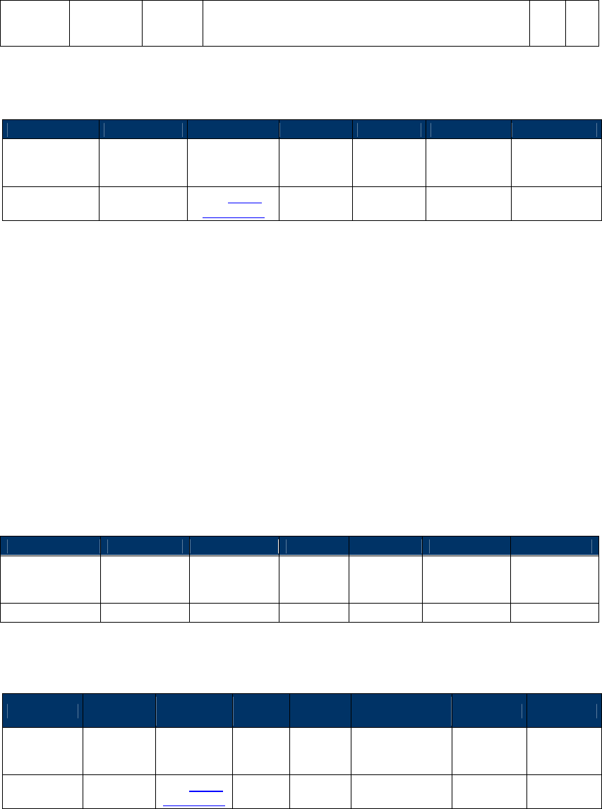
NEO Interface Developers Guide
134
It is MANDATORY to include the Group Number TLV of the Group the user wishes to delete. No
other TLVs should be included.
FFE4[1] Group
Number MAND
The group that contains the properties for AID
Note: This must be the ONLY TLV in Data Field. n2 1
[1]
These objects use proprietary tags. The use of these tags should be restricted to the serial interface. Once the reader
has received these values and saved them in memory, the Terminal should dispose of the tags.
Response Frame
Byte 0-9
Byte 10
Byte 11
Byte 12
Byte 13
Byte 14
Byte 15
Header Tag &
Protocol
Version
Command Status Code
Data
Length
(MSB)
Data
Length
(LSB)
CRC (MSB) CRC (LSB)
ViVOtech2\0 04h
See Status
Code Table 00h 00h
Do NOT delete the Default Group 0. The reader does not allow this command, and does NOT
disable Group 0; instead it returns an error.
If the Group is not a valid Group Number this returns an error.
Finally, if the reader has ANY AID that references this Group, it does NOT delete the Group. It
returns an error. That is, ONLY Groups that are NOT referenced by existing AID can be deleted.
In this situation, the user must first delete or modify these AIDs, and then delete the Group.
Get All AIDs (03-05)
Use this command to return all AIDs in the reader. This command may be used to verify
configured AIDs or to determine what System AIDs are in the reader.
Command Frame
Byte 0-9
Byte 10
Byte 11
Byte 12
Byte 13
Byte 14
Byte 15
Header Tag &
Protocol
Version
Command Sub-
Command
Data
Length
(MSB)
Data
Length
(LSB)
CRC (LSB) CRC (MSB)
ViVOtech2\0
03h
05h
00h
00h
Response Frame
Byte 0-9 Byte 10 Byte 11 Byte 12
Byte 13
Byte 14 …
Byte 14+n-1
Byte 14+n
Byte 15+n
Header Tag
& Protocol
Version
Command
Status Code
Data
Length
(MSB)
Data
Length
(LSB)
Data CRC (MSB)
CRC
(LSB)
ViVOtech2\0
03h
See Status
Code Table
TLV Data
Objects
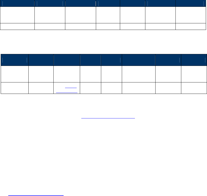
NEO Interface Developers Guide
135
The only Data Objects that should be returned from the GAA command are AID Tags. The reader
sends out ALL TLV associated with each AID.
The reader sends one or more frames with all the AID TLVs in it. Each AID grouping begins with
the Group Number TLV that this AID uses. The user can use this fact to parse between the AID
groups passed back to the POS.
Get All Groups (03-07)
This command returns all Groups in the reader. This command may be used to verify all
configured Groups in the reader.
Command Frame
Byte 0-9
Byte 10
Byte 11
Byte 12
Byte 13
Byte 14
Byte 15
Header Tag &
Protocol
Version
Command Sub-
Command
Data
Length
(MSB)
Data
Length
(LSB)
CRC (LSB) CRC (MSB)
ViVOtech2\0
03h
07h
00h
00h
Response Frame
Byte 0-9 Byte 10 Byte 11 Byte 12
Byte 13
Byte 14 …
Byte 14+n-1 Byte 14+n
Byte 15+n
Header Tag
& Protocol
Version
Command
Status Code
Data
Length
(MSB)
Data
Length
(LSB)
Data CRC (MSB)
CRC
(LSB)
ViVOtech2\0
03h
See Status
Code Table
TLV Data
Objects
The only Data Objects that should be returned from the GAG command are Group Tags. These
are the same as those itemized in the Group Configuration Tags table.
The reader sends one or more frames with all the Group TLVs in it. Each Group begins with the
Group Number TLV for the Group in question. The user can use this fact to parse between the
Groups passed back to the POS.
Transaction Related Commands: Contact
This section describes contact EMV commands applicable to UniPay 1.5, UniPay III, and
applicable VP4880-series products that support contact EMV. For contactless transactions, see
the chapter following this one.
NEO Interface Developers Guide
136
Setting transaction parameters
1. Send Contact Set Application Data Command (60-03);
2. Send Contact Set Terminal Data Command (60-06);
3. Send Contact Set CA Public Key Command (60-08);
4. Send Contact Set Certification Revocation List Command (60-0E)

NEO Interface Developers Guide
137
Contact EMV L2 Transaction Flow
1. Send Start Transaction Command.
2. Send Authenticate Transaction Command.
3. If received online request from terminal, send Apply Host Response command.
4. When a transaction is completed, interface will output a TLV format data list, and
transaction result (approve, or decline, or…) will display on the LCD.
5. If you want to review the transaction result, you can send Retrieve Transaction Result
Command. It will output the TLV format data; refer to the Option Data list.
offline
Offline
Host
Reade
r
Start contact transaction command (60-10)
Example:72 46 05 01……
Start
contact
transaction response
If MSR operation , response MSR data, and transaction is
finished
Contact
Authentication transaction command (60-11)
Example:72 46 05 02……
Contact Authentication response
Example :06 00 03 00 <TLVs>
Contact Apply host command (60-12)
Example :72 46 05 03……
Contact Apply host response
Example : 06 00 02 00 <TLVs>
Online
Online
If command is OK, first response 0x63
Display or Select Manu Command (61-01)
If need select menu, response command (61-01)
If command is OK, first response 0x63
Display or PIN Entry command (61-01, 61-02)
If need PIN entry response (61-02)
If command is ok, first response 0x63

NEO Interface Developers Guide
138
Retrieve EMV Level Two Version Number command can be sent at any time.
Cancel Transaction command can be sent at any time if you want to terminate a transaction.
Contact Retrieve Application Data (60-01)
This command returns the User AID parameters. The host must send AID in the command. The reader then
returns all tags associated with that User AID in response.
Command Frame
Byte 0-9 Byte 10 Byte 11 Byte 12
Byte 13
Byte 14 …
Byte 14+n-1
Byte
14+n
Byte
15+n
Header Tag
& Protocol
Version
Command
Sub-
Command
Data
Length
(MSB)
Data
Length
(LSB)
Data CRC
(LSB)
CRC
(MSB)
ViVOtech2\0
60h 01h Data Objects
Data Objects: <5~16 bytes AID>
Response Frame
Byte 0-9 Byte 10 Byte 11 Byte 12
Byte 13
Byte 14 …
Byte 14+n-1 Byte 14+n
Byte 15+n
Header Tag
& Protocol
Version
Command
Status Code
Data
Length
(MSB)
Data
Length
(LSB)
Data CRC
(MSB)
CRC
(LSB)
ViVOtech2\
0 60h
See
Status
Code
Table
See Response
Frame Data
Format
Response Frame Data Format: <TagCounterL> <TagCounterH> <TLV1> <TLV2>…<TLVn>
Where:
<TagCounterL> <TagCounterH> is the number of <TLV> tags.
Note:
If AID List / Application Data does not exist, status code is 0x60.
Contact Remove Application Data (60-02)
This command deletes a configurable AID. It is mandatory to include the AID TLV of the AID to
be removed.

NEO Interface Developers Guide
139
Command Frame
Byte 0-9 Byte 10 Byte 11 Byte 12
Byte 13
Byte 14 …
Byte 14+n-1
Byte
14+n
Byte
15+n
Header Tag
& Protocol
Version
Command
Sub-
Command
Data
Length
(MSB)
Data
Length
(LSB)
Data CRC
(LSB)
CRC
(MSB)
ViVOtech2\0
60h 02h Data Objects
Data Objects: <5~16 bytes AID>
If length is 00 then remove all Application Data.
Response Frame
Byte 0-9 Byte 10 Byte 11 Byte 12
Byte 13
Byte 14 …
Byte 14+n-1 Byte 14+n
Byte 15+n
Header Tag
& Protocol
Version
Command
Status Code
Data
Length
(MSB)
Data
Length
(LSB)
Data CRC
(MSB)
CRC
(LSB)
ViVOtech2\
0 60h
See
Status
Code
Table
See Response
Frame Data
Format
Note:
If AID List / Application Data not exist, status code is 0x60.
If format was error, status code is 0x05.
Contact Set Application Data (60-03)
This command creates a new AID configuration. Maximum is 16 sets
Command Frame
Byte 0-9 Byte 10 Byte 11 Byte 12
Byte 13
Byte 14 …
Byte 14+n-1
Byte
14+n
Byte
15+n
Header Tag
& Protocol
Version
Command
Sub-
Command
Data
Length
(MSB)
Data
Length
(LSB)
Data CRC
(LSB)
CRC
(MSB)
ViVOtech2\0
60h 03h Data Objects
Data Objects: <AID_LenL><AID_LenH><5~16 bytes AID> <TagCounterL> <TagCounterH> <TLV1>
<TLV2>…<TLVn>.
Where:

NEO Interface Developers Guide
140
<TagCounterL> <TagCounterH>is the Number of <TLV>.
Response Frame
Byte 0-9 Byte 10 Byte 11 Byte 12
Byte 13
Byte 14 …
Byte 14+n-1 Byte 14+n
Byte 15+n
Header Tag
& Protocol
Version
Command
Status Code
Data
Length
(MSB)
Data
Length
(LSB)
Data CRC
(MSB)
CRC
(LSB)
ViVOtech2\
0 60h
See
Status
Code
Table
See Response
Frame Data
Format
Note:
If a <TLV> format was error, status code is 0x05.
If AID List has full (MAX is 16), status code is 0x61.
Application Data List Example
Data
ID
Tag Value name Length
(Byte)
Data
1 9F01 Acquirer Identifier 6 56 49 53 41
30 30
2 5F57 Account Type 1 00
3 5F2A Transaction Currency 2 08 40
4 9F09 Terminal application version number 2 00 96
5 5F36 Transaction Currency Exponent 1 02
6 9F1B Terminal Floor Limit 4 00 00 3A 98
7 DF25 Default DDOL Var 9F 37 04
8 DF28 Default TDOL Var 9F 08 02
9 DFEE15 ASI 1 01
10 DF13 TAC-Default 5 00 00 00 00
00
11 DF14 TAC-Denial 5 00 00 00 00
00
12 DF15 TAC-Online 5 00 00 00 00
00
13 DF18 Target Percentage For Random Transaction
Selection
1 00
14 DF17 Threshold Value for Biased Random Selection 4 00 00 27 10
15 DF19 Maximum Target Percentage For Random
Transaction Selection
1 00
Contact Retrieve Terminal Data (60-04)
Use this command to return all TLV associated the terminal data.

NEO Interface Developers Guide
141
Command Frame
Byte 0-9 Byte 10 Byte 11 Byte 12
Byte 13
Byte 14 …
Byte 14+n-1
Byte
14+n
Byte
15+n
Header Tag
& Protocol
Version
Command
Sub-
Command
Data
Length
(MSB)
Data
Length
(LSB)
Data CRC
(LSB)
CRC
(MSB)
ViVOtech2\0
60h 04h 00h 00h
Response Frame
Byte 0-9 Byte 10 Byte 11 Byte 12
Byte 13
Byte 14 …
Byte 14+n-1 Byte 14+n
Byte 15+n
Header Tag
& Protocol
Version
Command
Status Code
Data
Length
(MSB)
Data
Length
(LSB)
Data CRC
(MSB)
CRC
(LSB)
ViVOtech2\
0 60h
See
Status
Code
Table
See Response
Frame Data
Format
Response Frame Data Format: <TagCounterL> <TagCounterH> <TLV1> <TLV2>…<TLVn>
Note:
<TagCounterL> <TagCounterH> is the number of <TLV> tags.
If Terminal Data does not exist, status code is 0x60.
Contact Remove Terminal Data (60-05)
Use this command to delete terminal data.
Command Frame
Byte 0-9 Byte 10 Byte 11 Byte 12
Byte 13
Byte 14 …
Byte 14+n-1
Byte
14+n
Byte
15+n
Header Tag
& Protocol
Version
Command
Sub-
Command
Data
Length
(MSB)
Data
Length
(LSB)
Data CRC
(LSB)
CRC
(MSB)
ViVOtech2\0
60h 05h 00h 00h
Response Frame

NEO Interface Developers Guide
142
Byte 0-9 Byte 10 Byte 11 Byte 12
Byte 13
Byte 14 …
Byte 14+n-1 Byte 14+n
Byte 15+n
Header Tag
& Protocol
Version
Command
Status Code
Data
Length
(MSB)
Data
Length
(LSB)
Data CRC
(MSB)
CRC
(LSB)
ViVOtech2\
0 60h
See
Status
Code
Table
See Response
Frame Data
Format
If Terminal Data does not exist, status code is 0x60.
Contact Set Terminal Data (60-06)
This command creates a new terminal data. The terminal data is mandatory and seldom change
data.
Command Frame
Byte 0-9 Byte 10 Byte 11 Byte 12
Byte 13
Byte 14 …
Byte 14+n-1
Byte
14+n
Byte
15+n
Header Tag
& Protocol
Version
Command
Sub-
Command
Data
Length
(MSB)
Data
Length
(LSB)
Data CRC
(LSB)
CRC
(MSB)
ViVOtech2\0
60h 06h Data Objects
Data Objects: <TagCounterL> <TagCounterH> <TLV1> <TLV2>…<TLVn>.
Where:
<TagCounterL> <TagCounterH>: the Number of <TLV> tags.
Response Frame
Byte 0-9 Byte 10 Byte 11 Byte 12
Byte 13
Byte 14 …
Byte 14+n-1 Byte 14+n
Byte 15+n
Header Tag
& Protocol
Version
Command
Status Code
Data
Length
(MSB)
Data
Length
(LSB)
Data CRC
(MSB)
CRC
(LSB)
ViVOtech2\
0 60h
See
Status
Code
Table
See Response
Frame Data
Format
Note:
If a <TLV> format was error, status code is 0x05.

NEO Interface Developers Guide
143
If flash was error, status code is 0x62.
Terminal Data List Example
Data
ID
Tag Value name Length
(Byte)
Data
1 5F36 Transaction Currency Exponent 1 02
2 9F1A Terminal County Code 2 08 40
3 9F35 Terminal Type 1 21
4 9F33 Terminal Capability 3 60 28 C8
5 9F40 Additional Terminal Capability 5 F0 00 F0 A0
01
6 9F1E IFD Serial Number 8 54 65 72 6D
69 6E 61 6C
7 9F15 Merchant Category Code 2 12 34
8 9F16 Merchant Identifier 15 30 30 30 30
30 30 30 30
30 30 30 30
30 30 30
9 9F1C Terminal Identification 8 38 37 36 35
34 33 32 31
10 9F4E Merchant Name and Location <=64 31 30 37 32
31 20 57 61
6C 6B 65 72
20 53 74 2E
20 43 79 70
72 65 73 73
2C 20 43 41
20 2C 55 53
41 2E
11 DF26 Terminal Supports CRL 1 01
12 DF10 Language Var. up to 128
65 6E 66 72
65 73 7A 68
13 DF11 Support Transaction Log 1 00
14 DF27 support Exception File 1 00
15 DFEE15 Terminal Support ASI 1 01
16 DFEE16 Terminal Encrypt Mode 1 00
17 DFEE17 Terminal Entry Mode for ICC 1 07
18 DFEE18 Terminal Encrypt Mode for MSR 1 80
19 DFEE1E Contact Terminal Configuration 8 D0 DC 20 D0
C4 1E 16 00
20 DFEE1F Issuer Script Limit 1 80
21 DFEE1B ARC Define 8 30 30 30 31
35 31 30 30
22 DFEE20 ICC Power on detect waiting time 1 3C
23 DFEE21 ICC L1 waiting time 1 0A
24 DFEE22 Driver waiting time. byte 1 -> Menu. byte 2 -> Get
PIn. byte 3 -> MSR
3 32 3C 3C
Contact Common EMV L2 comes with approved 4 configurations of certification. Parameters
marked as Major cannot, in general, be changed, although certain flag bits (see tables below)
can be changed.
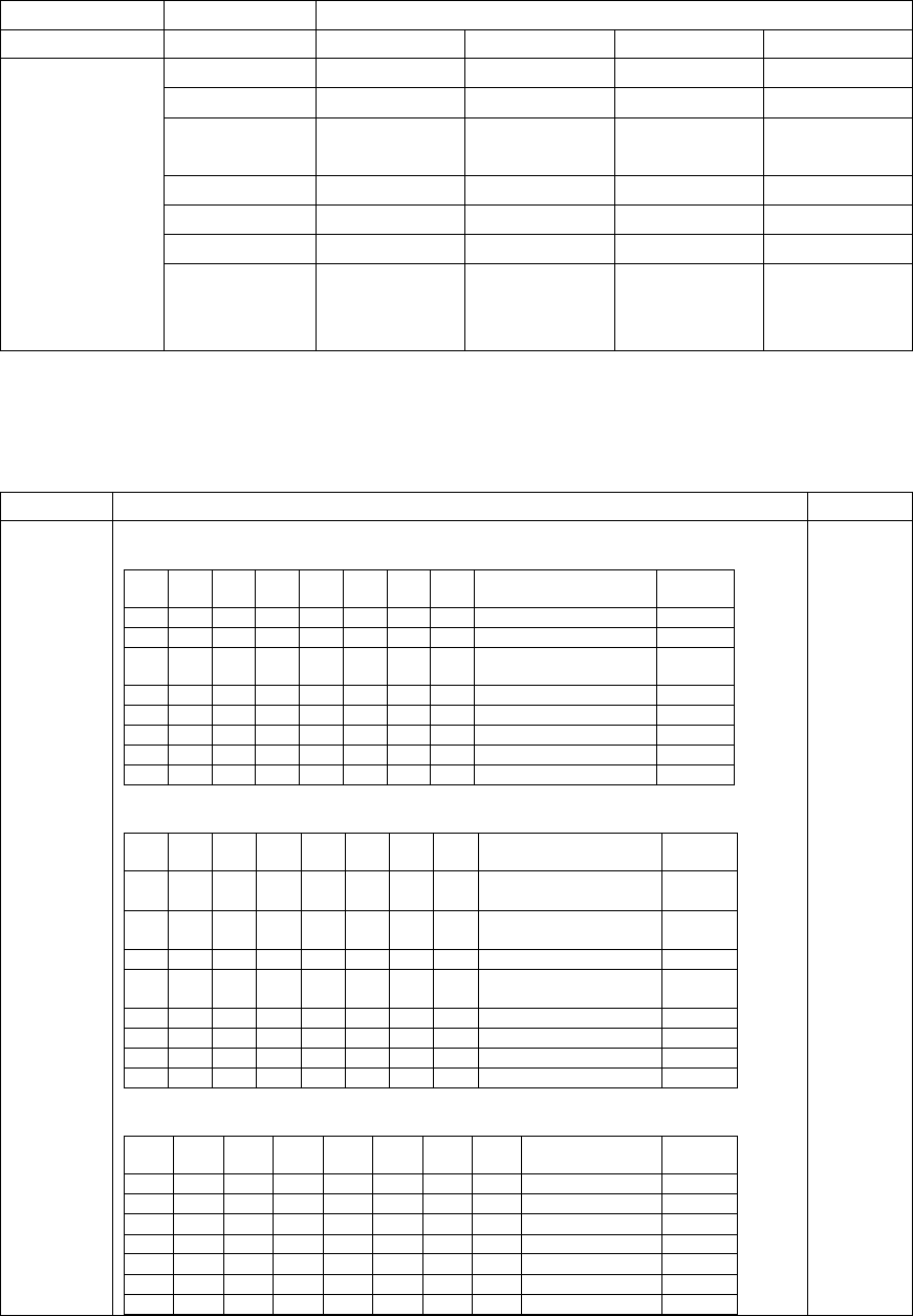
NEO Interface Developers Guide
144
Terminal configuration
Identification
Tag 1C 2C 3C 4C
Major
parameters
9F33
60 F8 C8
60 28 C8
60 D8 C8
60 08 C8
9F35
22
21
25
25
9F40
F0 00 F0 A0
01
F0 00 F0 A0
01
60 00 F0 50
01
60 00 F0 50
01
DF11
01
00
01
01
DF26
01
01
01
01
DF27
00
00
00
00
DFEE1E
F0 DC 3C
F0 C2 9E 96
00
D0 DC 20
D0 C4 1E
16 00
F0 DC 24
F0 C2 0E 16
00
D0 9C 20
F0 C2 0E 16
00
Tag Description Length
9F33
Terminal Capabilities
Byte 1
b8
b7
b6
b5
b4
b3
b2
b1
Meaning
Change
1
x
x
x
x
x
x
x
Manual key entry
x
1
x
x
x
x
x
x
Magnetic stripe
x
x
1
x
x
x
x
x
IC with contacts
Major
x
x
x
0
x
x
x
x
RFU
x
x
x
x
0
x
x
x
RFU
x
x
x
x
x
0
x
x
RFU
x
x
x
x
x
x
0
x
RFU
x
x
x
x
x
x
x
0
RFU
Byte 2
b8
b7
b6
b5
b4
b3
b2
b1
Meaning
Change
1
x
x
x
x
x
x
x
Plaintext PIN for IC
verification
Major
x
1
x
x
x
x
X
x
Enciphered PIN for
online verification
Major
x
x
1
x
x
x
X
x
Signature(paper)
Major
x
x
x
1
x
x
X
x
Enciphered PIN for
offline verification
Major
x
x
x
x
1
x
X
x
No CVM Required
Major
x
x
x
x
x
0
x
x
RFU
x
x
x
x
x
x
0
x
RFU
x
x
x
x
x
x
X
0
RFU
Byte 3
b8
b7
b6
b5
b4
b3
b2
b1
Meaning
Change
1
x
x
x
x
x
x
x
SDA
Major
X
1
x
x
x
x
x
x
DDA
Major
X
x
1
x
x
x
x
x
Card capture
x
x
x
0
x
x
x
x
RFU
x
x
x
x
1
x
x
X
CDA
Major
x
x
x
x
x
0
x
x
RFU
x
x
x
x
x
x
0
x
RFU
3
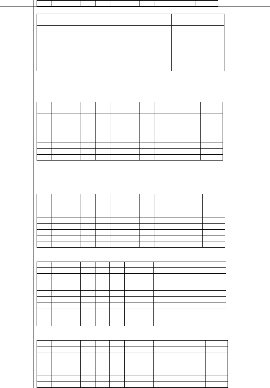
NEO Interface Developers Guide
145
x
x
x
x
X
X
x
0
RFU
9F35
Terminal Type
Environment
Financial
Institution
Merchant
Cardholder
Change
Attended
Online only
Offline with online capability
Offline only
11
12
13
21
22
23
--
--
--
Major
Unattended
Online only
Offline with online capability
Offline only
14
15
16
24
25
26
34
35
36
Major
1
9F40
Additional Terminal Capabilities
Byte 1
b1
b2
b3
b4
b5
b6
b7
b8
Meaning
Change
1
x
x
x
x
x
x
x
Cash
Major
x
1
x
x
x
x
x
x
Goods
Major
x
x
1
x
x
x
x
x
Services
Major
x
x
x
1
x
x
x
x
Cashback
Major
x
x
x
x
1
x
x
x
Inquiry
x
x
x
x
x
1
x
x
Transfer
x
x
x
x
x
x
1
x
Payment
x
x
x
x
x
x
x
1
Administrative
Byte 2
b8
b7
b6
b5
b4
b3
b2
b1
Meaning
Change
1
x
x
x
x
x
x
x
Cash Deposit
x
0
x
x
x
x
x
x
RFU
x
x
0
x
x
x
x
x
RFU
x
x
x
0
x
x
x
x
RFU
x
x
x
x
0
x
x
x
RFU
x
x
x
x
x
0
x
x
RFU
x
x
x
x
x
x
0
x
RFU
x
x
x
x
x
x
x
0
RFU
Byte 3
b8
b7
b6
b5
b4
b3
b2
b1
Meaning
Change
1
x
x
x
x
x
x
x
Numeric keys
x
1
x
x
x
x
x
x
Alphabetic and
special characters
keys
x
x
1
x
x
x
x
x
Command keys
x
x
x
1
x
x
x
x
Function Keys
x
x
x
x
0
x
x
x
RFU
x
x
x
x
x
0
x
x
RFU
x
x
x
x
x
x
0
x
RFU
x
x
x
x
x
x
x
0
RFU
Byte 4
b8
b7
b6
b5
b4
b3
b2
b1
Meaning
Change
1
x
x
x
x
x
x
x
Print, attendant
x
1
x
x
x
x
x
x
Print, cardholder
x
x
1
x
x
x
x
x
Display, attendant
x
x
x
1
x
x
x
x
Display, cardholder
x
x
x
x
0
x
x
x
RFU
x
x
x
x
x
0
x
x
RFU
x
x
x
x
x
x
1
x
Code table 10
Major
5
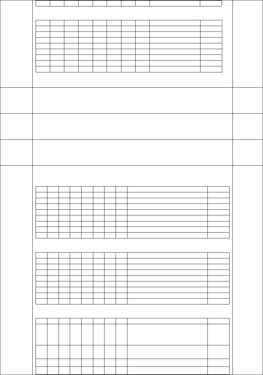
NEO Interface Developers Guide
146
x
x
x
x
x
x
x
1
Code table 9
Major
Byte 5
b8
b7
b6
b5
b4
b3
b2
b1
Meaning
Change
1
x
x
x
x
x
x
x
Code table 8
Major
x
1
x
x
x
x
x
x
Code table 7
Major
x
x
1
x
x
x
x
x
Code table 6
Major
x
x
x
1
x
x
x
x
Code table 5
Major
x
x
x
x
1
x
x
x
Code table 4
Major
x
x
x
x
x
1
x
x
Code table 3
Major
x
x
x
x
x
x
1
x
Code table 2
Major
x
x
x
x
x
x
x
1
Code table 1
Major
DF11
Transaction Log Support (Default: Enable) (Major)
0 Disable
1 Enable
1
DF26
Revocation List Support (Default: Enable) (Major)
0 Disable
1 Enable
1
DF27
Exception File Support (Default: Disable) (Major)
0 Disable
1 Enable
1
DFEE1E
Contact Terminal Configuration (Default: F0 DC 3C F0 C2 9E 94 00)
Byte 1
b8
b7
b6
b5
b4
b3
b2
b1
Meaning
Change
1
x
x
x
x
x
x
x
Key Pad support
x
1
x
x
x
x
x
x
LCD support
x
x
1
x
x
x
x
x
PIN Pad support
x
x
x
1
x
x
x
x
Print Support
x
x
x
x
0
x
x
x
RFU
x
x
x
x
x
0
x
x
RFU
x
x
x
x
x
x
0
x
RFU
x
x
x
x
x
x
X
0
RFU
Byte 2
b8
b7
b6
b5
b4
b3
b2
b1
Meaning
Change
1
x
x
x
x
x
x
x
PSE support
Major
x
1
x
x
x
x
x
x
Cardholder confirmation
Major
x
x
1
x
x
x
x
x
Preferred display order
x
x
x
1
x
x
x
x
Multi language
x
x
x
x
1
x
x
x
EMV language selection method
x
x
x
x
x
1
x
x
Default DDOL
Major
x
x
x
x
x
x
0
x
RFU
x
x
x
x
x
x
x
0
RFU
Byte 3
b8
b7
b6
b5
b4
b3
b2
b1
Meaning
Change
0
x
x
x
x
x
x
x
RFU
(Revocation of Issuer Public Key
Certificate (DF26))
Major
x
1
x
x
x
x
x
x
Manual action when CA PK loading
fails
Major
x
x
1
x
x
x
x
x
CA PK verified with check sum Major
x
x
x
1
x
x
x
x
Bypass PIN Entry Major
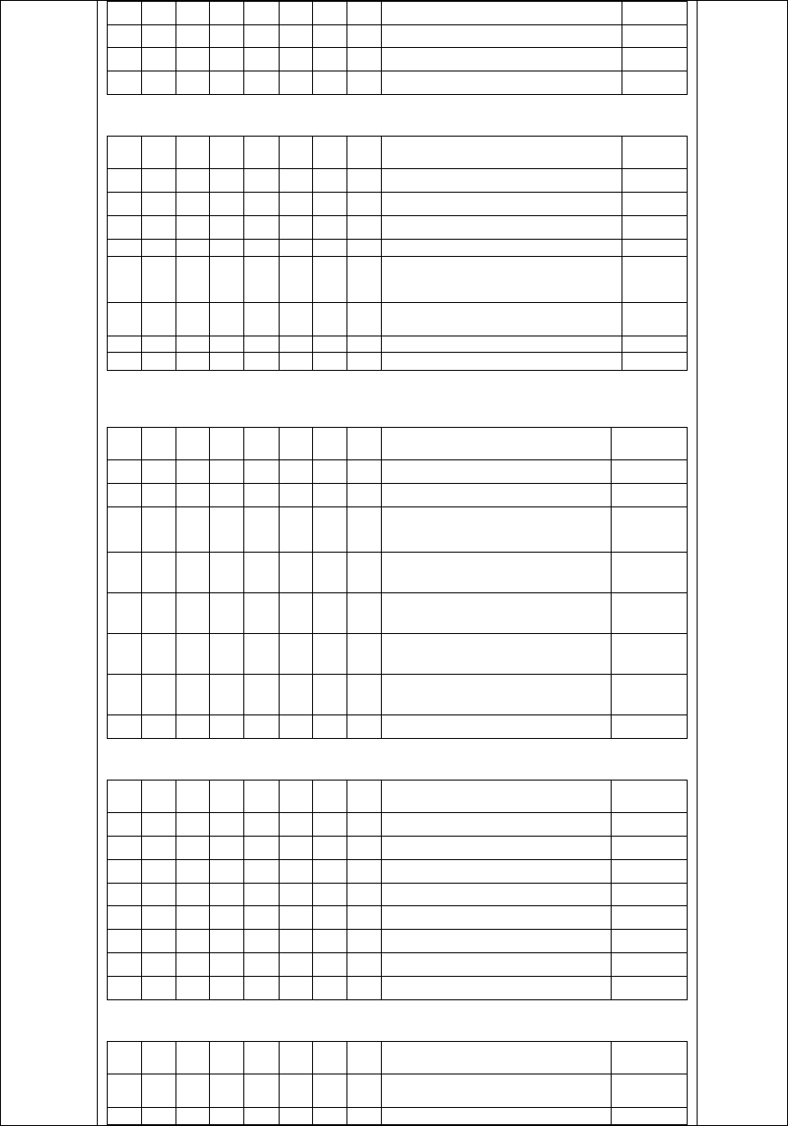
NEO Interface Developers Guide
147
x
x
x
x
1
x
x
x
Subsequent bypass PIN Entry Major
x
x
x
x
x
1
x
x
Get data for pin try counter
Major
x
x
x
x
x
x
0
x
RFU
x
x
x
x
x
x
x
0
RFU
Byte 4
b8
b7
b6
b5
b4
b3
b2
b1
Meaning
Change
1
x
x
x
x
x
x
x
Amount before CVM processing Major
x
1
x
x
x
x
x
x
Floor limit checking Major
x
x
1
x
x
x
x
x
Random transaction selection Major
x
x
x
1
x
x
x
x
Velocity checking
Major
x
x
x
x
0
x
x
x
RFU
(Transaction Log (DF11))
Major
x
x
x
x
x
0
x
x
RFU
(Exception File (DF27))
Major
x
x
x
x
x
x
0
x
RFU
x
x
x
x
x
x
x
0
RFU
Byte 5
b8
b7
b6
b5
b4
b3
b2
b1
Meaning
Change
1
x
x
x
x
x
x
X
Terminal action code support Major
x
1
x
x
x
x
x
x
Terminal action code can be change
Major
x
x
1
x
x
x
x
x
Terminal action code can be deleted
or disable
Major
x
x
x
1
x
x
x
x
Default Action code processing
before 1st GAC
Major
x
x
x
x
1
x
x
x
Default Action code processing after
1st GAC
Major
x
x
x
x
x
1
x
x
TAC/IAC default process when
unable to go online (Skipped)
Major
x
x
x
x
x
x
1
x
TAC/IAC default process when
unable to go online (Normal)
Major
x
x
x
x
x
x
x
0
RFU
Byte 6
b8
b7
b6
b5
b4
b3
b2
b1
Meaning
Change
1
x
x
x
x
x
x
x
Forced Online support Major
x
1
x
x
x
x
x
x
Forced acceptance support Major
x
x
1
x
x
x
x
x
Advices support Major
x
x
x
1
x
x
x
x
Issuer referrals support Major
X
x
x
x
1
x
x
x
Batch data capture Major
x
x
x
x
x
1
x
x
Online data capture Major
X
x
x
x
x
x
1
x
Default TDOL Major
X
x
x
x
x
x
x
0
RFU
Byte 7
b8
b7
b6
b5
b4
b3
b2
b1
Meaning
Change
1
x
x
x
x
x
x
x
amount and pin entered on the
same keypad
x
1
x
x
x
x
x
x
ICC/Magstripe reader combined
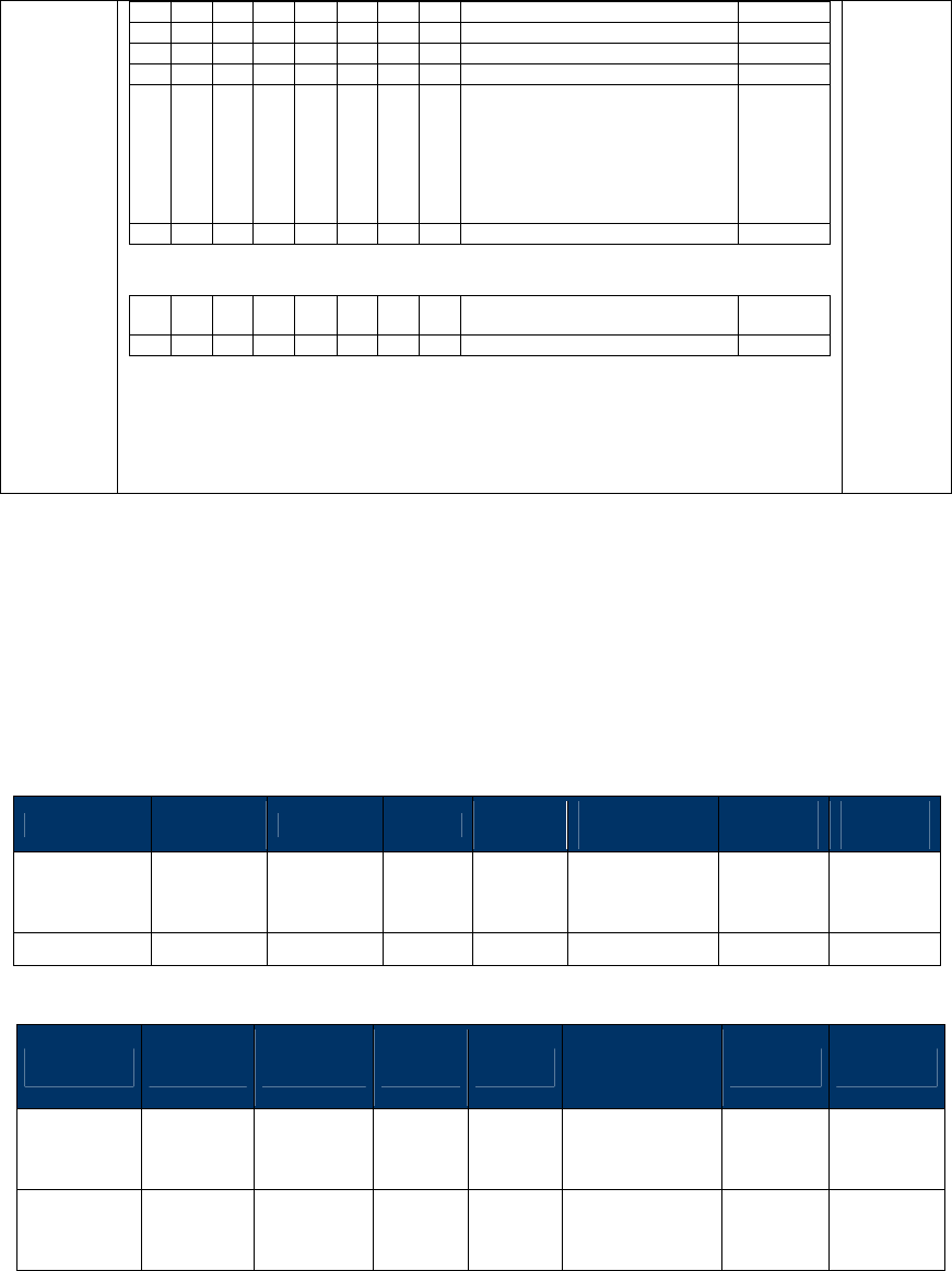
NEO Interface Developers Guide
148
x
x
1
x
x
x
x
x
Magstripe read first
x
x
x
1
x
x
x
x
Support account type selection
x
x
x
x
1
x
x
x
On fly script processing
x
x
x
x
x
1
x
x
Internal date management
x
x
x
x
x
x
1
x
Reversal Mode
(1)Unable go online
(2) ARC Error
0: (3) Online Approved but
reader not approved.
1: (3) Online Approved but card
response AAC.
x
x
x
x
x
x
x
0
RFU
Byte 8
b8
b7
b6
b5
b4
b3
b2
b1
Meaning
Change
x
x
x
x
x
x
x
x
RFU
Contact Retrieve AID List (60-07)
Use this command to return all AIDs list in the reader. This command may be used to verify
configured AIDs in the reader.
Command Frame
Byte 0-9 Byte 10 Byte 11 Byte 12
Byte 13
Byte 14 …
Byte 14+n-1
Byte
14+n
Byte
15+n
Header Tag
& Protocol
Version
Command
Sub-
Command
Data
Length
(MSB)
Data
Length
(LSB)
Data CRC
(LSB)
CRC
(MSB)
ViVOtech2\0
60h 07h 00h 00h
Response Frame
Byte 0-9 Byte 10 Byte 11 Byte 12
Byte 13
Byte 14 …
Byte 14+n-1 Byte 14+n
Byte 15+n
Header Tag
& Protocol
Version
Command
Status Code
Data
Length
(MSB)
Data
Length
(LSB)
Data CRC
(MSB)
CRC
(LSB)
ViVOtech2\
0 60h
See
Status
Code
Table
See Response
Frame Data
Format
Response Frame Data Format: <NumberL><NumberH> <AID Block 1> <AID Block 2> … <AID Block
N>.

NEO Interface Developers Guide
149
Where:
<NumberL><NumberH> is Number of AID Blocks.
<AID Block> format is <LenL> <LenH> <Several bytes AID>.
Note:
If AID List does not exist, status code is 0x60.
Contact Retrieve CA Public Key (60-08)
This command can get assign CA Public key form reader.
Command Frame
Byte 0-9 Byte 10 Byte 11 Byte 12
Byte 13
Byte 14 …
Byte 14+n-1
Byte
14+n
Byte
15+n
Header Tag
& Protocol
Version
Command
Sub-
Command
Data
Length
(MSB)
Data
Length
(LSB)
Data CRC
(LSB)
CRC
(MSB)
ViVOtech2\0
60h 08h Data Objects
Data Objects: <5 bytes RID> <1 byte Index>.
Response Frame
Byte 0-9 Byte 10 Byte 11 Byte 12
Byte 13
Byte 14 …
Byte 14+n-1 Byte 14+n
Byte 15+n
Header Tag
& Protocol
Version
Command
Status Code
Data
Length
(MSB)
Data
Length
(LSB)
Data CRC
(MSB)
CRC
(LSB)
ViVOtech2\
0 60h
See
Status
Code
Table
See Response
Frame Data
Format
Response Frame Data Format: <5 bytes RID> <1 byte Index> <1 byte Hash Algorithm> <1 byte
Encryption Algorithm> <20 bytes HashValue> <4 bytes Public Key Exponent> <2 bytes Modulus
Length> <Variable bytes Modulus>
Where:
<Hash Algorithm>: The only algorithm supported is SHA-1.The value is set to 0x01.
<Encryption Algorithm>: The encryption algorithm in which this key is used. Currently support
only one type: RSA. The value is set to 0x01.

NEO Interface Developers Guide
150
<HashValue>: Which is calculated using SHA-1 over the following fields: RID & Index & Modulus &
Exponent
<Public Key Exponent>: Actually, the real length of the exponent is either one byte or 3 bytes. It
can have two values: 3, or 65537
<Modulus Length>: <LenH> <LenL> Indicated the length of the next field.
<Modulus>: This is the modulus field of the public key. Its length is specified in the field above.
Note:
If CA Key RID does not exist, status code is 0x60.
If CA Key Index does not exist, status code is 0x60.
Contact Remove CA Public Key (60-09)
This command allows the host to delete a specific key.
Command Frame
Byte 0-9 Byte 10 Byte 11 Byte 12
Byte 13
Byte 14 …
Byte 14+n-1
Byte
14+n
Byte
15+n
Header Tag
& Protocol
Version
Command
Sub-
Command
Data
Length
(MSB)
Data
Length
(LSB)
Data CRC
(LSB)
CRC
(MSB)
ViVOtech2\0
60h 09h Data Objects
Data Objects: <5 bytes RID> <1 byte Index>.
If length is 00 then remove all CA Public Key.
Response Frame
Byte 0-9 Byte 10 Byte 11 Byte 12
Byte 13
Byte 14 …
Byte 14+n-1 Byte 14+n
Byte 15+n
Header Tag
& Protocol
Version
Command
Status Code
Data
Length
(MSB)
Data
Length
(LSB)
Data CRC
(MSB)
CRC
(LSB)
ViVOtech2\
0 60h
See
Status
Code
Table
00h 00h
Note:
If CA Key RID does not exist, status code is 0x60.

NEO Interface Developers Guide
151
If CA Key Index does not exist, status code is 0x60.
Contact Set CA Public Key (60-0A)
This command adds a new key to reader. Maximum is 16 sets.
Command Frame
Byte 0-9 Byte 10 Byte 11 Byte 12
Byte 13
Byte 14 …
Byte 14+n-1
Byte
14+n
Byte
15+n
Header Tag
& Protocol
Version
Command
Sub-
Command
Data
Length
(MSB)
Data
Length
(LSB)
Data CRC
(LSB)
CRC
(MSB)
ViVOtech2\0
60h 0Ah Data Objects
Data Objects: <5 bytes RID> <1 byte Index> <1 byte Hash Algorithm> <1 byte Encryption
Algorithm> <20 bytes HashValue> <4 bytes Public Key Exponent> <2 bytes Modulus Length>
<Variable bytes Modulus>
Where:
<Hash Algorithm>: The only algorithm supported is SHA-1.The value is set to 0x01
<Encryption Algorithm>: The encryption algorithm in which this key is used. Currently support
only one type: RSA. The value is set to 0x01.
<HashValue>: Which is calculated using SHA-1 over the following fields: RID & Index & Modulus &
Exponent
<Public Key Exponent>: Actually, the real length of the exponent is either one byte or 3 bytes. It
can have two values: 3, or 65537
<Modulus Length>: <LenH> <LenL> Indicated the length of the next field.
<Modulus>: This is the modulus field of the public key. Its length is specified in the field above.
Response Frame
Byte 0-9 Byte 10 Byte 11 Byte 12
Byte 13
Byte 14 …
Byte 14+n-1 Byte 14+n
Byte 15+n
Header Tag
& Protocol
Version
Command
Status Code
Data
Length
(MSB)
Data
Length
(LSB)
Data CRC
(MSB)
CRC
(LSB)
ViVOtech2\
0 60h
See
Status
Code
Table
00h 00h
Note:

NEO Interface Developers Guide
152
If key slots are full, status code is 0x61.
If CA Key Hash Data is an error, status code is 0x17.
Contact Retrieve CA Public Key List (60-0B)
This command can get all RID and key index for CA public key.
Command Frame
Byte 0-9 Byte 10 Byte 11 Byte 12
Byte 13
Byte 14 …
Byte 14+n-1
Byte
14+n
Byte
15+n
Header Tag
& Protocol
Version
Command
Sub-
Command
Data
Length
(MSB)
Data
Length
(LSB)
Data CRC
(LSB)
CRC
(MSB)
ViVOtech2\0
60h 0Bh 00h 00h
Response Frame
Byte 0-9 Byte 10 Byte 11 Byte 12
Byte 13
Byte 14 …
Byte 14+n-1 Byte 14+n
Byte 15+n
Header Tag
& Protocol
Version
Command
Status Code
Data
Length
(MSB)
Data
Length
(LSB)
Data CRC
(MSB)
CRC
(LSB)
ViVOtech2\
0 60h
See
Status
Code
Table
Data Objects
Data Objects : <5Bytes RID1> <1 byte RID1 Index><5Bytes RID2> <1 byte RID2 Index>….. <5Bytes
RIDN> <1 byte RIDN Index>.
Note:
If any CA Key does not exist, status code is 0x60.
Contact Retrieve Certification Revocation List (60-0C)
This command retrieves a sequence of consecutive records from the EMV revocation list.
Command Frame
Byte 0-9 Byte 10 Byte 11 Byte 12
Byte 13
Byte 14 …
Byte 14+n-1
Byte
14+n
Byte
15+n
Header Tag
& Protocol
Version
Command
Sub-
Command
Data
Length
(MSB)
Data
Length
(LSB)
Data CRC
(LSB)
CRC
(MSB)
ViVOtech2\0
60h 0Ch 00h 00h

NEO Interface Developers Guide
153
Response Frame
Byte 0-9 Byte 10 Byte 11 Byte 12
Byte 13
Byte 14 …
Byte 14+n-1 Byte 14+n
Byte 15+n
Header Tag
& Protocol
Version
Command
Status Code
Data
Length
(MSB)
Data
Length
(LSB)
Data CRC
(MSB)
CRC
(LSB)
ViVOtech2\
0 60h
See
Status
Code
Table
Data Objects
Data Objects : <CRL Length L><CRL Length H><CRL1><CRL2>…<CRLn>.
<CRL>format is <5Bytes RID><1Byte CA public key Index><3Bytes Certificate Serial Number>.
Note:
If have no CRL exist, status code is 0x60.
Contact Remove Certification Revocation List (60-0D)
This command deletes a specific entry from the EMV revocation list. Unlike the commands
described previously, this command deletes the specific entry that matches the RID, the key
index, and the certificate serial number.
Command Frame
Byte 0-9 Byte 10 Byte 11 Byte 12
Byte 13
Byte 14 …
Byte 14+n-1
Byte
14+n
Byte
15+n
Header Tag
& Protocol
Version
Command
Sub-
Command
Data
Length
(MSB)
Data
Length
(LSB)
Data CRC
(LSB)
CRC
(MSB)
ViVOtech2\0
60h 0Dh Data Objects
Data Objects : <CRL1><CRL2>…<CRLn>.
<CRL>format is <5Bytes RID><1Byte CA public key Index><3Bytes Certificate Serial Number>.
If Length is 00 then remove all Certification Revocation List.
Response Frame

NEO Interface Developers Guide
154
Byte 0-9 Byte 10 Byte 11 Byte 12
Byte 13
Byte 14 …
Byte 14+n-1 Byte 14+n
Byte 15+n
Header Tag
& Protocol
Version
Command
Status Code
Data
Length
(MSB)
Data
Length
(LSB)
Data CRC
(MSB)
CRC
(LSB)
ViVOtech2\
0 60h
See Status
Code
Table
00h 00h
Contact Set Certification Revocation List (60-0E)
This command adds a new entry to the revocation list. The new entry is added at the end of the
revocation list.
Command Frame
Byte 0-9 Byte 10 Byte 11 Byte 12
Byte 13
Byte 14 …
Byte 14+n-1
Byte
14+n
Byte
15+n
Header Tag
& Protocol
Version
Command
Sub-
Command
Data
Length
(MSB)
Data
Length
(LSB)
Data CRC
(LSB)
CRC
(MSB)
ViVOtech2\0
60h 0Eh Data Objects
Data Objects: <CRL Total Length L><CRL Total Length H>
<CRL1><CRL2>…<CRLn><2 Bytes MAC Length>.
<CRL>format is <5Bytes RID><1Byte CA public key Index><3Bytes Certificate Serial Number>
<2Byte Length of CRL> (Option): <Low byte of length> <High byte of length>
Fix is 0x00 0x00.
Response Frame
Byte 0-9 Byte 10 Byte 11 Byte 12
Byte 13
Byte 14 …
Byte 14+n-1 Byte 14+n
Byte 15+n
Header Tag
& Protocol
Version
Command
Status Code
Data
Length
(MSB)
Data
Length
(LSB)
Data CRC
(MSB)
CRC
(LSB)
ViVOtech2\
0 60h
See Status
Code
Table
00h 00h
Note:

NEO Interface Developers Guide
155
Supported max CRL number is 90. If exceed max number, status code is 0x61.
Contact Remove Transaction Amount Log (60-0F)
This command can delete transaction amount log in reader. (When EMV transaction is offline
approved, or online, transaction amount log saves to reader.)
Command Frame
Byte 0-9 Byte 10 Byte 11 Byte 12
Byte 13
Byte 14 …
Byte 14+n-1
Byte
14+n
Byte
15+n
Header Tag
& Protocol
Version
Command
Sub-
Command
Data
Length
(MSB)
Data
Length
(LSB)
Data CRC
(LSB)
CRC
(MSB)
ViVOtech2\0
60h 0Fh 00h 00h
Response Frame
Byte 0-9 Byte 10 Byte 11 Byte 12
Byte 13
Byte 14 …
Byte 14+n-1 Byte 14+n
Byte 15+n
Header Tag
& Protocol
Version
Command
Status Code
Data
Length
(MSB)
Data
Length
(LSB)
Data CRC
(MSB)
CRC
(LSB)
ViVOtech2\
0 60h
See Status
Code
Table
00h 00h
Contact Start Transaction (60-10)
Start a new contact EMV L2 transaction (ICC + MSR) or start MSR only transaction.
This function will go through below processes at the EMV card inserted at the reader:
Card power on
Card activation
Application Selection
Initiate Application Processing
Get Process Options
Read Records

NEO Interface Developers Guide
156
Note: VP4880C not supported.
Command Frame
Byte 0-9 Byte 10 Byte 11 Byte 12
Byte 13
Byte 14 …
Byte 14+n-1
Byte
14+n
Byte
15+n
Header Tag
& Protocol
Version
Command
Sub-
Command
Data
Length
(MSB)
Data
Length
(LSB)
Data CRC
(LSB)
CRC
(MSB)
ViVOtech2\0
60h 10h Data Objects
Data Objects - <FallBack><TimeOut1> <TimeOut2> <App Data>.
Where:
<FallBack> (1byte). 0x01 indicate it support FallBack to MSR, 0x00 indicate it not support
FallBack.
<TimeOut1> (2 bytes, unit is Second). Timeout for Card is seated.
<TimeOut2> (2 bytes, unit is Second). Waiting time till “Authenticate Transaction” command.
<App Data> format is <TLV1> <TLV2> … <TLVn>. Refer to Transaction Data.
Transaction Data List (start command parameters)
Data
ID
Tag Value name Length
(Byte)
1 9F02 Amount, Authorized(Numeric) 6
2 9C Transaction Type 1
3 5F2A Transaction Currency Code 2
4 9A Transaction Date 3
5 9F21 Transaction Time 3
6 9F03 Amount, Other(Numeric) 6
7 DFEE1A Output Tag List (Options) N
8 DFEE27 MSR Control. (Options)
MSR only transaction need set this tag.
1 MSR Only Enable
0 MSR Only Disable
1
9 DFEF1F Auto Authenticate (Options)
If auto authenticate set to 1, the reader will do
command 60-11 automatic.
Byte 1: Auto Authenticate enable
1: enable, 0 disable
Byte 2: Force Online 1: enable, 0 disable
2
If command parse is successful and ICC transaction starts, response contains first command and
status code is 0x63.
If command parse fails, response is other status code and end transaction.

NEO Interface Developers Guide
157
Note:
After transaction start, terminal only can receive “Start Transaction”, “Authenticate
Transaction”, “Cancel Transaction,” and “Retrieve Transaction Data” commands. If any other
command is sent, it gets a response of 0x0C.
No Terminal data response 0x60.
First Response Frame
Byte 0-9 Byte 10 Byte 11 Byte 12
Byte 13
Byte 14 …
Byte 14+n-1 Byte 14+n
Byte 15+n
Header Tag
& Protocol
Version
Command
Status Code
Data
Length
(MSB)
Data
Length
(LSB)
Data CRC
(MSB)
CRC
(LSB)
ViVOtech2\
0 60h
See Status
Code
Table
00h 00h
Because reader doesn’t support LCD and key pad, so need external host to display messages and
allow key-in.
When transaction needs display or key-in, it sends command 61-01 to host.
If host response is needed, host will response command 61-01 and result to reader.
On Start Transaction success, send second response and result to host.
Second Response Frame
Byte 0-9 Byte 10 Byte 11 Byte 12
Byte 13
Byte 14 …
Byte 14+n-1 Byte 14+n
Byte 15+n
Header Tag
& Protocol
Version
Command
Status Code
Data
Length
(MSB)
Data
Length
(LSB)
Data CRC
(MSB)
CRC
(LSB)
ViVOtech2\
0 60h 00h Data Objects
Contact EMV L2 Data Objects:

NEO Interface Developers Guide
158
Data Item Length (bytes) Description
Attribution 1 Bit 4/3/0: Captured Data Type
0 0 0 = Contact Card
0 0 1 = Contactless Card / EMV
1 0 1 = Contactless Card / MSD
0 1 x = MSR Card
Bit 2/1: Encryption Mode
0 0 = TDES
0 1 = AES
1 x = Reserved
Bit 5: Reserved for Attribution Byte Extension.
Bit 6/7: Encryption Status
0 0 = MSR/MSD off, EMV off
0 1 = MSR/MSD off, EMV on
1 0 = MSR/MSD on, EMV off
1 1 = MSR/MSD on, EMV on
TLV KSN
(FFEE12)
Variable If encrypt disable, this tag is not present.
Contact Response
Code
(DFEE25)
Variable See Contact Response Code
TLV Data Variable Output default Start Transaction Output TLV data list. If set tag
DFEE1A, The TLV data will be follow list.
TLV POS Entry
Mode (9F39)
Variable 90h = Magnetic Stripe Reader Swipe
91h = Contactless MSD
05h = Contact EMV
07h = Contactless EMV
80h = Contact Fallback to Magnetic Stripe
TLV (DF30)
(ViVOpay
proprietary)
Variable Track Data Source.
This tag is embedded in the ViVOpay Group tag. It specifies
whether the track data came from a swipe or contactless
transaction.
0Ch for swiped MagStripe
00h for a contactless card.
01h for a contact card.
This tag is included in ViVOpay proprietary (FFEE01)
Ex: FFEE0104DF30010C

NEO Interface Developers Guide
159
Data Item Length (bytes) Description
TLV Encrypt
Information
(DFEE26)
Variable Encrypt Information.
Length: 1 byte
Values: Same as “Attribution” byte definition
Bit 4/3/0: Captured Data Type
0 0 0 = Contact Card
0 0 1 = Contactless Card / EMV
1 0 1 = Contactless Card / MSD
0 1 x = MSR Card
Bit 2/1: Encryption Mode
0 0 = TDES
0 1 = AES
1 x = Reserved
Bit 5: Reserved for Attribution Byte Extension.
Bit 6/7: Encryption Status
0 0 = MSR/MSD off, EMV off
0 1 = MSR/MSD off, EMV on
1 0 = MSR/MSD on, EMV off
1 1 = MSR/MSD on, EMV on
MSR Data Objects:
Data Item Length
(bytes) Description
Attribution 1 Bit 4/3/0: Captured Data Type
0 0 0 = Contact Card
0 0 1 = Contactless Card / EMV
1 0 1 = Contactless Card / MSD
0 1 x = MSR Card
Bit 2/1: Encryption Mode
0 0 = TDES
0 1 = AES
1 x = Reserved
Bit 5: Reserved for Attribution Byte Extension.
Bit 6/7: Encryption Status
0 0 = MSR/MSD off, EMV off
0 1 = MSR/MSD off, EMV on
1 0 = MSR/MSD on, EMV off
1 1 = MSR/MSD on, EMV on
Contact Response
Code
(DFEE25)
Variable
See Contact Response Code. (00h 11h).
TLV Data Variable
TLV data list
MSR Tag
(DFEE23)
Variable
Data follow Enhanced Encrypted MSR FIELD DATA. Refer NEO
spec to Appendix A.11: Enhanced Encrypted MSR Data Output
Format

NEO Interface Developers Guide
160
Data Item Length
(bytes) Description
TLV POS Entry
Mode (9F39)
Variable
90h = Magnetic Stripe Reader Swipe
91h = Contactless MSD
05h = Contact EMV
07h = Contactless EMV
80h = Contact Fallback to Magnetic Stripe
TLV (DF30)
(ViVOpay
proprietary)
Variable
Track Data Source.
This tag is embedded in the ViVOpay Group tag. It specifies whether
the track data came from a swipe or RFID transaction.
0Ch for swiped MagStripe
00h for a contactless card.
01h for a contact card.
This tag include in ViVOpay proprietary (FFEE01)
Ex: FFEE0104DF30010C
TLV Encrypt
Information
(DFEE26)
Variable
Encrypt Information.
Length: 1 byte
Values: Same as “Attribution” byte definition
Bit 4/3/0: Captured Data Type
0 0 0 = Contact Card
0 0 1 = Contactless Card / EMV
1 0 1 = Contactless Card / MSD
0 1 x = MSR Card
Bit 2/1: Encryption Mode
0 0 = TDES
0 1 = AES
1 x = Reserved
Bit 5: Reserved for Attribution Byte Extension.
Bit 6/7: Encryption Status
0 0 = MSR/MSD off, EMV off
0 1 = MSR/MSD off, EMV on
1 0 = MSR/MSD on, EMV off
1 1 = MSR/MSD on, EMV on
1. For MSR <Response Code> is 00 11.
2. MSR data in tag DFEE23, format is following “Enhanced Encrypted MSR Data Output Format”.
Default Start Transaction Output TLV Data List
Data
ID
Tag Value name Length
(Byte)
1 57 Track2 Equivalent Data <=19
2 5A PAN <=10
3 5F34 PAN Sequence Number 1
4 5F20 Cardholder Name 2~26
5 5F24 Application Expire Date 3
6 9F20 Track2 Discretionary Data Var.
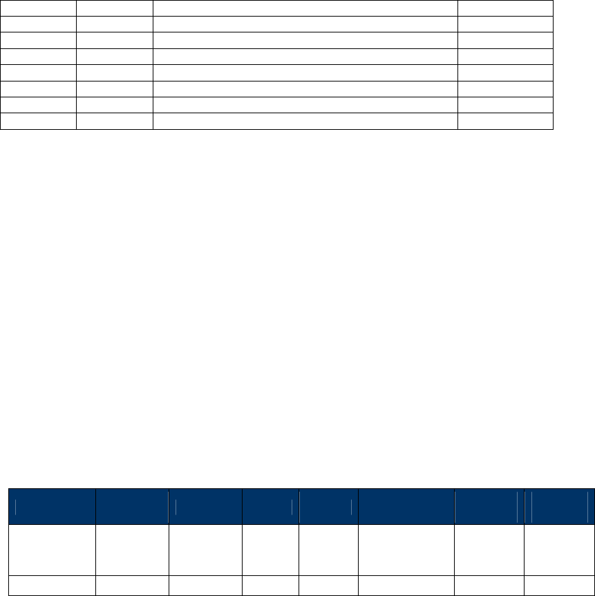
NEO Interface Developers Guide
161
7 5F25 Application Effective Date 3
8 5F2D Language Preference 2~8
9 50 Application Label 1~16
10 84/4F DF Name or ADF Name 5~16
11 DFEE23 MSR Data N
12 9F39 POS Entry Mode 1
13 DF30 Track Data Source. 1
14 DFEE26 Encrypt Information 1
Contact Authenticate Transaction (60-11)
This function must after Start Transaction function.
The function will continue to perform the EMV transaction flow:
(1) Offline data auth
(2) Processing restrictions
(3) Cardholder Verification
(4) Terminal risk management
(5) TAA/CAA/1st Gen AC
If response code is 00 04, then need go online process and send Apply Host Response command.
Note: VP4880C does not support this.
Command Frame
Byte 0-9 Byte 10 Byte 11 Byte 12
Byte 13
Byte 14 …
Byte 14+n-1
Byte
14+n
Byte
15+n
Header Tag
& Protocol
Version
Command
Sub-
Command
Data
Length
(MSB)
Data
Length
(LSB)
Data CRC
(LSB)
CRC
(MSB)
ViVOtech2\0
60h 11h Data Objects
Data Objects : <ForeOnline><TimeOut> <Output Data List>-.
<ForeOnline>(1byte). 0x01 indicate it support ForeOnline, 0x00 indicate not support.
<TimeOut> (2 byte, unit is Second).means terminal waiting time for host response when online.-
<Output Tag List DFEE1A> format is <TLV> (V is output tag list.)
Ex: DEFF1A 06 95 5A 84 9F39 50
If command parse is successful and ICC transactions continue, response is first command and
status code is 0x63.
If command parse fails, response is some other status code and end of transaction.

NEO Interface Developers Guide
162
First Response Frame
Byte 0-9 Byte 10 Byte 11 Byte 12
Byte 13
Byte 14 …
Byte 14+n-1 Byte 14+n
Byte 15+n
Header Tag
& Protocol
Version
Command
Status Code
Data
Length
(MSB)
Data
Length
(LSB)
Data CRC
(MSB)
CRC
(LSB)
ViVOtech2\
0 60h
See Status
Code
Table
00h 00h
When transaction needs display or Get PIN, reader sends command 61-01, 61-02 to host.
If host response is needed, host should respond with command 61-01, 61-02 and send result to
reader.
Authenticate Transaction success: send second response and result to host.
Second Response Frame
Byte 0-9 Byte 10 Byte 11 Byte 12
Byte 13
Byte 14 …
Byte 14+n-1 Byte 14+n
Byte 15+n
Header Tag
& Protocol
Version
Command
Status Code
Data
Length
(MSB)
Data
Length
(LSB)
Data CRC
(MSB)
CRC
(LSB)
ViVOtech2\
0 60h 00h Data Objects
Data Objects:

NEO Interface Developers Guide
163
Data Item Length
(bytes) Description
Attribution 1 Bit 4/3/0: Captured Data Type
0 0 0 = Contact Card
0 0 1 = Contactless Card / EMV
1 0 1 = Contactless Card / MSD
0 1 x = MSR Card
Bit 2/1: Encryption Mode
0 0 = TDES
0 1 = AES
1 x = Reserved
Bit 5: Reserved for Attribution Byte Extension.
Bit 6/7: Encryption Status
0 0 = MSR/MSD off, EMV off
0 1 = MSR/MSD off, EMV on
1 0 = MSR/MSD on, EMV off
1 1 = MSR/MSD on, EMV on
TLV KSN
(FFEE12)
Variable
If encrypt disable, this tag is not present.
Contact Response
Code
(DFEE25)
Variable
See Contact Response Code.
If response code is 00 04, then need go online process and send Apply
Host Response command.
TLV Data Variable
Output default Authenticate Transaction Output TLV data list. If set
tag DFEE1A, The TLV data will be follow list.
Default Authenticate Transaction Output TLV Data List
Data
ID
Tag Value name Length
(Byte)
1 9F10 Issuer Application Data Var. up to 32
2 9F26 Application Cryptogram 8
3 9F27 Cryptogram Information Data 1
4 9F36 Application Transaction Counter(ATC) 2
5 9F37 Unpredictable Number 4
6 9F02 Amount, Authorized (Numeric) 6
7 9F4D Log Entry 2
8 9F4F Log Format Var.
9 9F13 Last Online Application Transaction Counter(ATC)
Register
2
10 95 Terminal Verification Results 5
11 9B Transaction Status Information 2
12 9F03 Amount, Other (Numeric) 6
13 9F34 Cardholder Verification Method(CVM) Results 3
14 9F39 POS Entry Mode 1
15 DF30 Track Data Source. 1
16 DFEE26 Encrypt Information 1

NEO Interface Developers Guide
164
Contact Apply Host Response (60-12)
This function is the last step in EMV transaction flow.
The function will send acquirer data (if online) to the card and notify that the transaction is
complete. This function will do the following process upon the transaction type (may or may not
perform each step, depending upon acquirer’s requirement and response):
(1) External Authenticate
(2) Script Processing
(3) 2nd Gen AC
(4) Completion
Note: VP4880C does not support this command.
Command Frame
Byte 0-9 Byte 10 Byte 11 Byte 12
Byte 13
Byte 14 …
Byte 14+n-1
Byte
14+n
Byte
15+n
Header Tag
& Protocol
Version
Command
Sub-
Command
Data
Length
(MSB)
Data
Length
(LSB)
Data CRC
(LSB)
CRC
(MSB)
ViVOtech2\0
60h 12h Data Objects
Data Objects : <1Byte ComFlag> [<Authorization Response Code (TLV,Tag 8A)>< Issuer
Authentication Data (TLV, Tag 91)>< <Scripts (TLV, Tag 71/72)>] <Output Data List>
Where:
<1Byte ComFlag>:0x01 indicate online with host,0x00 indicate unable online.
Data in [ ] indicate these data is optional:
If ComFlag is 0x01, the Data exist.
If ComFlag is 0x00, the Data does not exist.
<Output Tag List DFEE1A> format is <TLV> (V is output tag list.)
Ex: DEFF1A 06 95 5A 84 9F39 50
If command parse is success and ICC transactions continue, response first command and status
code is 0x63.
If command parse is failed, response other status code and end transaction.

NEO Interface Developers Guide
165
First Response Frame
Byte 0-9 Byte 10 Byte 11 Byte 12
Byte 13
Byte 14 …
Byte 14+n-1 Byte 14+n
Byte 15+n
Header Tag
& Protocol
Version
Command
Status Code
Data
Length
(MSB)
Data
Length
(LSB)
Data CRC
(MSB)
CRC
(LSB)
ViVOtech2\
0 60h
See Status
Code
Table
00h 00h
When transaction needs display or key in, it sends command 61-01 to host.
If need host response, host will response command 61-01 and result to reader.
Second Response Frame
Byte 0-9 Byte 10 Byte 11 Byte 12
Byte 13
Byte 14 …
Byte 14+n-1 Byte 14+n
Byte 15+n
Header Tag
& Protocol
Version
Command
Status Code
Data
Length
(MSB)
Data
Length
(LSB)
Data CRC
(MSB)
CRC
(LSB)
ViVOtech2\
0 60h 00h Data Objects

NEO Interface Developers Guide
166
Data Objects:
Data Item Length
(bytes) Description
Attribution 1 Bit 4/3/0: Captured Data Type
0 0 0 = Contact Card
0 0 1 = Contactless Card / EMV
1 0 1 = Contactless Card / MSD
0 1 x = MSR Card
Bit 2/1: Encryption Mode
0 0 = TDES
0 1 = AES
1 x = Reserved
Bit 5: Reserved for Attribution Byte Extension.
Bit 6/7: Encryption Status
0 0 = MSR/MSD off, EMV off
0 1 = MSR/MSD off, EMV on
1 0 = MSR/MSD on, EMV off
1 1 = MSR/MSD on, EMV on
TLV KSN
(FFEE12)
Variable
If encrypt disable, this tag is not present.
Contact Response
Code
(DFEE25)
Variable
See Contact Response Code.
TLV Data Variable
Output default Apply Host Response Output TLV data list. If set tag
DFEE1A, The TLV data will be follow list.
Default Apply Host Response Output TLV Data List
Data
ID
Tag Value name Length
(Byte)
1 9F10 Issuer Application Data Var. up to 32
2 9F26 Application Cryptogram 8
3 9F27 Cryptogram Information Data 1
4 9F36 Application Transaction Counter(ATC) 2
5 9F37 Unpredictable Number 4
6 9F02 Amount, Authorized (Numeric) 6
7 9F4D Log Entry 2
8 9F4F Log Format Var.
9 9F13 Last Online Application Transaction Counter(ATC)
Register
2
10 95 Terminal Verification Results 5
11 9B Transaction Status Information 2
12 9F03 Amount, Other (Numeric) 6
13 9F34 Cardholder Verification Method(CVM) Results 3
14 99 PIN Block Var.
15 9F5B Issuer Script Results Var. up to 128
16 9F39 POS Entry Mode 1
17 DF30 Track Data Source. 1
18 DFEE26 Encrypt Information 1

NEO Interface Developers Guide
167
Contact Retrieve Transaction Result (60-13)
After EMV transaction is completed, you can use this command to get other TLVs.
Note: VP4880C does not support this command.
Command Frame
Byte 0-9 Byte 10 Byte 11 Byte 12
Byte 13
Byte 14 …
Byte 14+n-1
Byte
14+n
Byte
15+n
Header Tag
& Protocol
Version
Command
Sub-
Command
Data
Length
(MSB)
Data
Length
(LSB)
Data CRC
(LSB)
CRC
(MSB)
ViVOtech2\0
60h 13h Data Objects
Data Objects : <Tags>.
<Tags> these tags will return TLV format. Supported tags refer to “Option Data List” Table in
Section “Reference Data List”.
Tags Example:
9F029F36959F37 means total 4 tags (9F02, 9F36, 95, 9F37) requested to in response. Length is 7
bytes.
Response Frame
Byte 0-9 Byte 10 Byte 11 Byte 12
Byte 13
Byte 14 …
Byte 14+n-1 Byte 14+n
Byte 15+n
Header Tag
& Protocol
Version
Command
Status Code
Data
Length
(MSB)
Data
Length
(LSB)
Data CRC
(MSB)
CRC
(LSB)
ViVOtech2\
0 60h
See Status
Code
Table
Data Objects
Data Objects:

NEO Interface Developers Guide
168
Data Item Length
(bytes) Description
Attribution 1 Bit 4/3/0: Captured Data Type
0 0 0 = Contact Card
0 0 1 = Contactless Card / EMV
1 0 1 = Contactless Card / MSD
0 1 x = MSR Card
Bit 2/1: Encryption Mode
0 0 = TDES
0 1 = AES
1 x = Reserved
Bit 5: Reserved for Attribution Byte Extension.
Bit 6/7: Encryption Status
0 0 = MSR/MSD off, EMV off
0 1 = MSR/MSD off, EMV on
1 0 = MSR/MSD on, EMV off
1 1 = MSR/MSD on, EMV on
TLV KSN
(FFEE12)
Variable
If encrypt disable, this tag is not present.
TLV Data Variable
Output TLV data list.
Reference Data List
Tag Tag Tag Tag Tag Tag Tag
5F2A 98 9F02 9F16 9F21 9F39 4F
5F36 99 9F03 9F1A 9F22 9F3A 50
81 9A 9F04 9F1B 9F33 9F3C 57
8A 9B 9F06 9F1C 9F34 9F3D 58
95 9C 9F09 9F1D 9F35 9F40 5A
5F57 9F01 9F15 9F1E 9F37 9F41 5F20
5F24 5F25 5F28 5F2D 5F30 5F34 5F36
6F 71 72 73 82 84 87
88 8C 8D 8E 8F 90 91
92 93 94 97 9F05 9F07 9F08
9F0D 9F0E 9F0F 9F10 9F11 9F12 9F13
9F14 9F17 9F1F 9F20 9F23 9F26 9F27
9F2D 9F2E 9F2F 9F32 9F36 9F38 9F3B
9F42 9F43 9F44 9F45 9F46 9F47 9F48
9F49 9F4A 9F4B 9F4C 9F4D BF0C DF62
9F4E 9F5B DFEE15 DFEE16 DFEE17 DFEE18 DFEE19
DFEE1A DFEE1B DF11 DF14 DF15 DF17 DF18
DF19 DF20 DF21 DF22 DF25 DF26 DF27
DF28 DF10 DF40 DF41 DF42 DF43 DFEE1E
DFEE1F DFEE20 DFEE21 DFEE22 DFEE23 DFEE24 89
DF13
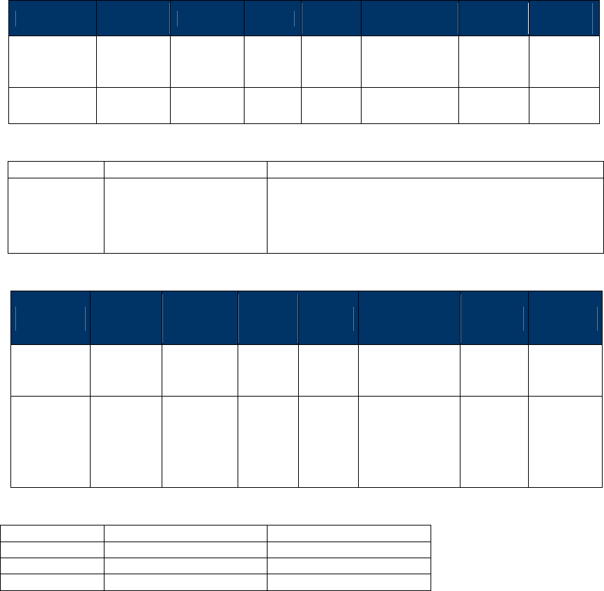
NEO Interface Developers Guide
169
Contact Get Reader Status (60-14)
This command can get ICC card power and card seat status.
Note: VP4880C does not support this command.
Command Frame
Byte 0-9 Byte 10 Byte 11 Byte 12
Byte 13
Byte 14 …
Byte 14+n-1
Byte
14+n
Byte
15+n
Header Tag
& Protocol
Version
Command
Sub-
Command
Data
Length
(MSB)
Data
Length
(LSB)
Data CRC
(LSB)
CRC
(MSB)
ViVOtech2\0
60h 14h Command
Data
Command Data
Data Item Length (bytes) Description/Example
Interface 1 20h = ICC
Response Frame
Byte 0-9 Byte 10 Byte 11 Byte 12
Byte 13
Byte 14 …
Byte 14+n-1 Byte 14+n
Byte 15+n
Header Tag
& Protocol
Version
Command
Status Code
Data
Length
(MSB)
Data
Length
(LSB)
Data CRC
(MSB)
CRC
(LSB)
ViVOtech2\
0 60h
See Status
Code
Table
Data Objects
Data Objects (1 byte)
Bit Position Meaning if ‘0’ Meaning if ‘1’
0 ICC Power not ready ICC Powered
1 Card not seated Card seated
2~7 RFU RFU
Contact Get ICS Identification (60-15)
Contact Common EMV L2 approved configurations of certification are 1C, 2C, 3C, and 4C. This
command can get identification of ICS terminal configuration in reader.

NEO Interface Developers Guide
170
Command Frame
Byte 0-9 Byte 10 Byte 11 Byte 12
Byte 13
Byte 14 …
Byte 14+n-1
Byte
14+n
Byte
15+n
Header Tag
& Protocol
Version
Command
Sub-
Command
Data
Length
(MSB)
Data
Length
(LSB)
Data CRC
(LSB)
CRC
(MSB)
ViVOtech2\0
60h 15h 00h 00h
Response Frame
Byte 0-9 Byte 10 Byte 11 Byte 12
Byte 13
Byte 14 …
Byte 14+n-1 Byte 14+n
Byte 15+n
Header Tag
& Protocol
Version
Command
Status Code
Data
Length
(MSB)
Data
Length
(LSB)
Data CRC
(MSB)
CRC
(LSB)
ViVOtech2\
0 60h
See Status
Code
Table
Response Data
Response Data:
0x01 Identification 1C
0x02 Identification 2C (Default)
0x03 Identification 3C
0x04 Identification 4C
Contact Set ICS Identification (60-16)
Contact Command EMV L2 includes 4 approved configurations of certification. This command
can set identification of ICS terminal configuration to reader. This command affects command
Contact Set Terminal Data (60-06). Generally, you will use 60-16 first, then 60-06.
Command Frame
Byte 0-9 Byte 10 Byte 11 Byte 12
Byte 13
Byte 14 …
Byte 14+n-1
Byte
14+n
Byte
15+n
Header Tag
& Protocol
Version
Command
Sub-
Command
Data
Length
(MSB)
Data
Length
(LSB)
Data CRC
(LSB)
CRC
(MSB)

NEO Interface Developers Guide
171
ViVOtech2\0
60h 16h 00h 01h ICS
Identification
ICS Identification:
0x01 Identification 1C
0x02 Identification 2C (Default)
0x03 Identification 3C
0x04 Identification 4C
Response Frame
Byte 0-9 Byte 10 Byte 11 Byte 12
Byte 13
Byte 14 …
Byte 14+n-1 Byte 14+n
Byte 15+n
Header Tag
& Protocol
Version
Command
Status Code
Data
Length
(MSB)
Data
Length
(LSB)
Data CRC
(MSB)
CRC
(LSB)
ViVOtech2\
0 60h
See Status
Code
Table
00 00
Contact LCD Display Control (61-01) (Reader send to Host)
Some readers do not incorporate LCD and keypad, so this command is sent to host. The
command requests display or key-in by host. If reader requests key-in, host response
should be 61-01 command and result sent to reader. This command is used in “60-10, 60-
11, 60-12” commands. When in those commands, command “61-01” sent to host
automatically.
Command Frame
Byte 0-9 Byte 10 Byte 11 Byte 12
Byte 13
Byte 14 …
Byte 14+n-1
Byte
14+n
Byte
15+n
Header Tag
& Protocol
Version
Command
Sub-
Command
Data
Length
(MSB)
Data
Length
(LSB)
Data CRC
(LSB)
CRC
(MSB)
ViVOtech2\0
61h 01h Data Objects
Data Objects:

NEO Interface Developers Guide
172
Data Item Length
(bytes) Description
Display Mode 1 0x01: Menu Display
0x02: Normal Display get function key
0x03: Display without key input(Do not receive input data)
0x08: Language Menu Display
0x10: Clear Screen(Do not receive input data)
(If Clear Screen, don’t need rod end below filed)
Timeout Length 2 Format: <Length L><Length H> (Little-endian)
If Display without key input. The value is 00 00.
Timeout Value Variable
Format: <Value L><Value H> (Little-endian)
If Normal Display or Menu Display, Total timeout for keypad entry,
in second. Default is 30 seconds.
Note: Total timeout will cancel keypad entry and return error.
Display Message
Language Length
2 Format: <Length L><Length H> (Little-endian)
Display Message
Language
Variable
Display Message Language, 2 byte
“EN” – English (default)
“ES” – Spanish
“ZH” – Chinese
“FR” – French
…
Display Message
Control Length
2 Format: <Length L><Length H> (Little-endian)
Display Message
Control
Variable
repeatable combination of <Line><Message><0x1C>
<Line> - Display line number (1-First Line, n-nth Line), Maximum 16
lines.
The lower 7 bits is for line number.
•The MSB is to indicate following message is a Message String or
Message ID.
•MSB – 0: Message String. (It is valid for “Menu Display” and
“Language Menu Display”)
•MSB – 1: Message ID. (It is only valid for “Menu Display”)
<Message> - Message String or Message ID.
Message String:
•“Menu Display” : character in the range of 0x20 – 0x7f,
Maximum 16 characters
• “Language Menu Display” : 2 bytes Language ID
“EN” – English (default)
“ES” – Spanish
“ZH” – Chinese
“FR” – French
…
Message ID: 1 byte, check LCD Foreign Language Mapping Table
<0x1C> - separator

NEO Interface Developers Guide
173
Data Item Length
(bytes) Description
Back Light Timer
Length
2 Format: <Length L><Length H> (Little-endian)
Back Light Timer
Value
Variable
Format: <Value L><Value H> (Little-endian)
Back Light On Timer Value in second.
(all 0-Back Light Off, all 0xff-Back Light always On)
Response Frame
Byte 0-9 Byte 10 Byte 11 Byte 12
Byte 13
Byte 14 …
Byte 14+n-1 Byte 14+n
Byte 15+n
Header Tag
& Protocol
Version
Command
Status Code
Data
Length
(MSB)
Data
Length
(LSB)
Data CRC
(MSB)
CRC
(LSB)
ViVOtech2\
0 61h 01h Data Objects
Data Objects:
Data Item Length
(bytes) Description
Display Mode 1 0x00- Cancel (user presses cancel key on the key pad for mode 1)
0x01 – Menu Display
0x02- Normal Display get function key
0x08- Language Menu Display
If Mode byte is “Cancel” or “Display without key input”, don’t
need to send below field.
Display Menu
Length
2 Format: <Length L><Length H> (Little-endian)
(If Normal Display, Length of Key (Get Function))
Display Menu Variable
Menu value, sequence number of selected line, hex format (If Normal
Display, ASCII format (‘E’ is Enter, ‘C’ is Cancel))
Contact Get PIN Control (61-02) (Reader send to Host)
Some readers do not incorporate a PIN Pad, so need to send this command to host. The
command requests Get PIN on PIN Pad. If the reader is requesting to “Get PIN”, the host

NEO Interface Developers Guide
174
responds with 61-02 command to reader and PIN Block. This command used in “60-11”
command only. When in the command, command “61-02” sent to host automatically.
Command Frame
Byte 0-9 Byte 10 Byte 11 Byte 12
Byte 13
Byte 14 …
Byte 14+n-1
Byte
14+n
Byte
15+n
Header Tag
& Protocol
Version
Command
Sub-
Command
Data
Length
(MSB)
Data
Length
(LSB)
Data CRC
(LSB)
CRC
(MSB)
ViVOtech2\0
61h 02h Data Objects
Data Objects:
Data Item Length
(bytes) Description
Mode 1 - 0x00 – Cancel (cancel through command)
- 0x01 – Online PIN DUKPT
- 0x02 – Online PIN MKSK
- 0x03 – Offline PIN
If Mode byte is “Cancel”, don’t need to send below field.
DATA PAIRING DUKPT
KSN Length
2 Format: <Length L><Length H> (Little-endian)
(If Mode is Online PIN have this filed)
If the value is 00 00, Device do not implement Pairing
Function.
DATA PAIRING DUKPT
KSN Value
Variable (If Mode is Online PIN have this filed)
If Length of DATA_PAIRING_DUKPT KSN is 00 00,
the block does not exist
Encrypted Truncated PAN
Length
2 Format: <Length L><Length H> (Little-endian)
(If Mode is Online PIN have this filed)
If Length of DATA_PAIRING_DUKPT KSN is 00 00,
PAN in Plaintext.
Encrypted Truncated PAN Variable (If Mode is Online PIN have this filed)
If Length of DATA_PAIRING_DUKPT KSN is 00 00,
PAN in Plaintext.
Start PIN Input Timeout
Length
2 Format: <Length L><Length H> (Little-endian)

NEO Interface Developers Guide
175
Data Item Length
(bytes) Description
Start PIN Input Timeout
Value
Variable Format: <Value L><Value H> (Little-endian)
Unit: Second
PIN Entry Interval Length 2 Format: <Length L><Length H> (Little-endian)
PIN Entry Interval Value Variable Format: <Value L><Value H> (Little-endian)
Unit: Second
Display Message Language
Length
2 Format: <Length L><Length H> (Little-endian)
Display Message Language
Variable “EN” – English (default)
“ES” – Spanish
“ZH” – Chinese
“FR” – French
…
Response Frame
Byte 0-9 Byte 10 Byte 11 Byte 12
Byte 13
Byte 14 …
Byte 14+n-1 Byte 14+n
Byte 15+n
Header Tag
& Protocol
Version
Command
Status Code
Data
Length
(MSB)
Data
Length
(LSB)
Data CRC
(MSB)
CRC
(LSB)
ViVOtech2\
0 61h 02h Data Objects
Data Objects:
Data Item Length
(bytes) Description
Mode 1 - 0x00 – Cancel (Can be cancel through command or user presses
cancel key on the key pad)
- 0x01 – Online PIN DUKPT. (PIN_KEY is PIN_DUKPT_KEY)
- 0x02 – Online PIN MKSK. (PIN_KEY is PIN_SESSION_KEY)
- 0x03 – Offline PIN. (PIN_KEY is PIN_PAIRING_DUKPT_KEY)
(If device do not implement Pairing function, Offline PIN is
Plaintext)
If Mode byte is “Cancel”, don’t need to send below field.
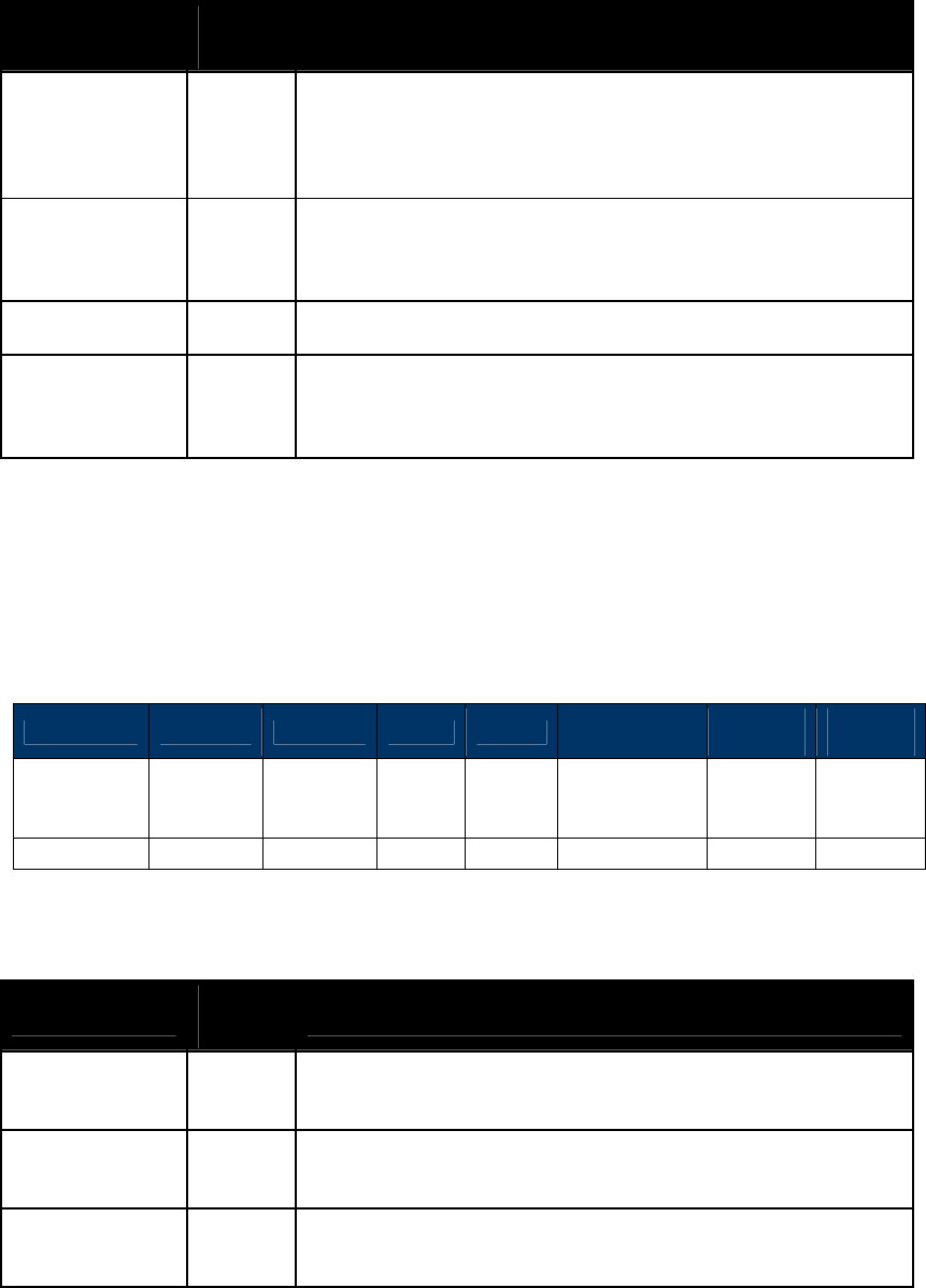
NEO Interface Developers Guide
176
Data Item Length
(bytes) Description
KSN Length 2 Format: <Length L><Length H> (Little-endian)
If Online PIN DUKPT, Length of PIN_DUKPT_KEY KSN
If Offline PIN, Length of PIN_PAIRING_DUKPT_KEY KSN.
(If device do not implement Pairing function, Offline PIN is Plaintext.
The Length Value is 00 00)
KSN Variable
If Online PIN DUKPT, PIN_DUKPT_KEY KSN – 10 bytes
If Offline PIN, PIN_PAIRING_DUKPT_KEY KSN.
(If device do not implement Pairing function, Offline PIN is Plaintext.
The Block does not exist.)
PIN Length 2 Format: <Length L><Length H> (Little-endian)
PIN Variable
If Online PIN DUKPT or Online PIN MKSK, Enciphered PIN
If Offline PIN, Enciphered PIN.
(If device do not implement Pairing function, Offline PIN is Plaintext)
Contact Get MSR Data Control (Reader send to Host)(61-03)
If reader is not MSR device, it can use this command to connect with external MSR device.
Command Frame
Byte 0-9 Byte 10 Byte 11 Byte 12
Byte 13
Byte 14 …
Byte 14+n-1
Byte
14+n
Byte
15+n
Header Tag
& Protocol
Version
Command
Sub-
Command
Data
Length
(MSB)
Data
Length
(LSB)
Data CRC
(LSB)
CRC
(MSB)
ViVOtech2\0
61h 03h Data Objects
Data Objects:
Data Item Length
(bytes) Description
Timeout Length 2 Format: <Length L><Length H> (Little-endian)
Length of Total timeout for Swipe MSR Card.
Timeout Value Variable
Format: <Value L><Value H> (Little-endian). Unit:Second
Total timeout for Swipe MSR Card, in second, default is 60
seconds.
Display Message
Language Length
2 Format: <Length L><Length H> (Little-endian)
Length of Display Message Language.

NEO Interface Developers Guide
177
Data Item Length
(bytes) Description
Display Message
Language
Variable
Display Message Language, 2 byte
“EN” – English (default)
“ES” – Spanish
“ZH” – Chinese
“FR” – French
…
Display Message
Control Length
2 Format: <Length L><Length H> (Little-endian)
Length Display Message Control – 2 bytes
Display Message
Control
Variable
repeatable combination of <Line><Message><0x1C>
<Line> - Display line number (1-First Line, n-nth Line), Maximum 16
lines.
The lower 7 bits is for line number.
•The MSB is to indicate following message is a Message String or
Message ID.
•MSB – 0: Message String. (It is valid for “Menu Display” and
“Language Menu Display”)
•MSB – 1: Message ID. (It is only valid for “Menu Display”)
<Message> - Message String or Message ID.
Message String:
•“Menu Display” : character in the range of 0x20 – 0x7f,
Maximum 16 characters
• “Language Menu Display” : 2 bytes Language ID
“EN” – English (default)
“ES” – Spanish
“ZH” – Chinese
“FR” – French
…
Message ID: 1 byte, check LCD Foreign Language Mapping Table
<0x1C> - separator
Response Frame
Byte 0-9 Byte 10 Byte 11 Byte 12
Byte 13
Byte 14 …
Byte 14+n-1 Byte 14+n
Byte 15+n
Header Tag
& Protocol
Version
Command
Status Code
Data
Length
(MSB)
Data
Length
(LSB)
Data CRC
(MSB)
CRC
(LSB)
ViVOtech2\
0 61h 00h MSR Data
Note: MSR Data for external MSR device max is 640 bytes. Tag DFEE23 data format will follow
external MSR format (see ID TECH document 80000502-001 for information on the Enhanced
Encrypted MSR Format).
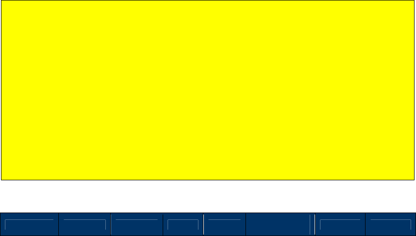
NEO Interface Developers Guide
178
Transaction Related Commands: Contactless
Activate Transaction Command, Contactless (02-01 and 02-40)
NOTE: 02-01 is a legacy command, applicable to non-encrypted transactions only.When EMV
mode encryption is ON or MSR/MSD encryption is ON, if Data encryption Key is loaded, 02-01
will be disabled. Use 02-40 for production; 02-40 is a unified command for both non-encrypted
and encrypted transactions, but if a key is present (unit is injected), encryption will occur.
Use the Activate Transaction command when the ViVOpay reader is in “Poll on Demand” mode
to begin a contactless EMV or contactless MagStripe Card transaction. When the reader is in
“Poll on Demand” mode, the RF is turned on only after receiving an Activate Transaction
command. When a valid Activate Transaction command is sent to the ViVOpay reader, it starts
polling for cards.
If the ViVOpay reader does not find a supported card (an AID that matches one of the configured
AIDs in the reader) for the specified time duration, it times out and ends the transaction. If the
ViVOpay reader finds a card within the specified time interval, it attempts to carry out the
transaction. The transaction flow between the reader and the card depends on the type of card
detected.
If the transaction is successful, the reader returns the data in the response data. If the
transaction is not successful, yet it proceeded into the transaction state machine, the reader
returns a Failed Transaction Record in the response data. The presence and format of the
Clearing Record, Track Data and Failed Transaction record depends on the type of card that was
detected.
Note: While an Activate command is in progress, only a Cancel or a Stop command may be
sent. Do not send other commands until Activate Transaction has completed, because the
reader will interpret these as a Cancel Transaction command.
Note: For Non-SRED version device, response format for Activate Transaction Command is
according to “Set Data Encryption Enable Flag (C7-36)” setting and Data encryption Key.
When Data Encryption is disabled, device responds with plaintext data format. When Data
Encryption is enabled: (1) When Data encryption Key exists and is valid, device responds with
encrypted data format. (2) When Data encryption Key does not exist, device responds with
plaintext data format (3) When Data encryption Key exhausts, device responds status code
0x91 and no data.
For SRED version device, response format for Activate Transaction Command is according to
Data encryption Key. When Data encryption Key exists and is valid, device responds with
encrypted data format. When Data encryption Key exhausts or does not exist, device
responds status code 0x91/0x90 and no data.
Command Frame
Byte 0-9 Byte 10 Byte 11 Byte 12
Byte 13
Byte 14 …
Byte 14+n-1 Byte 14+n
Byte 15+n
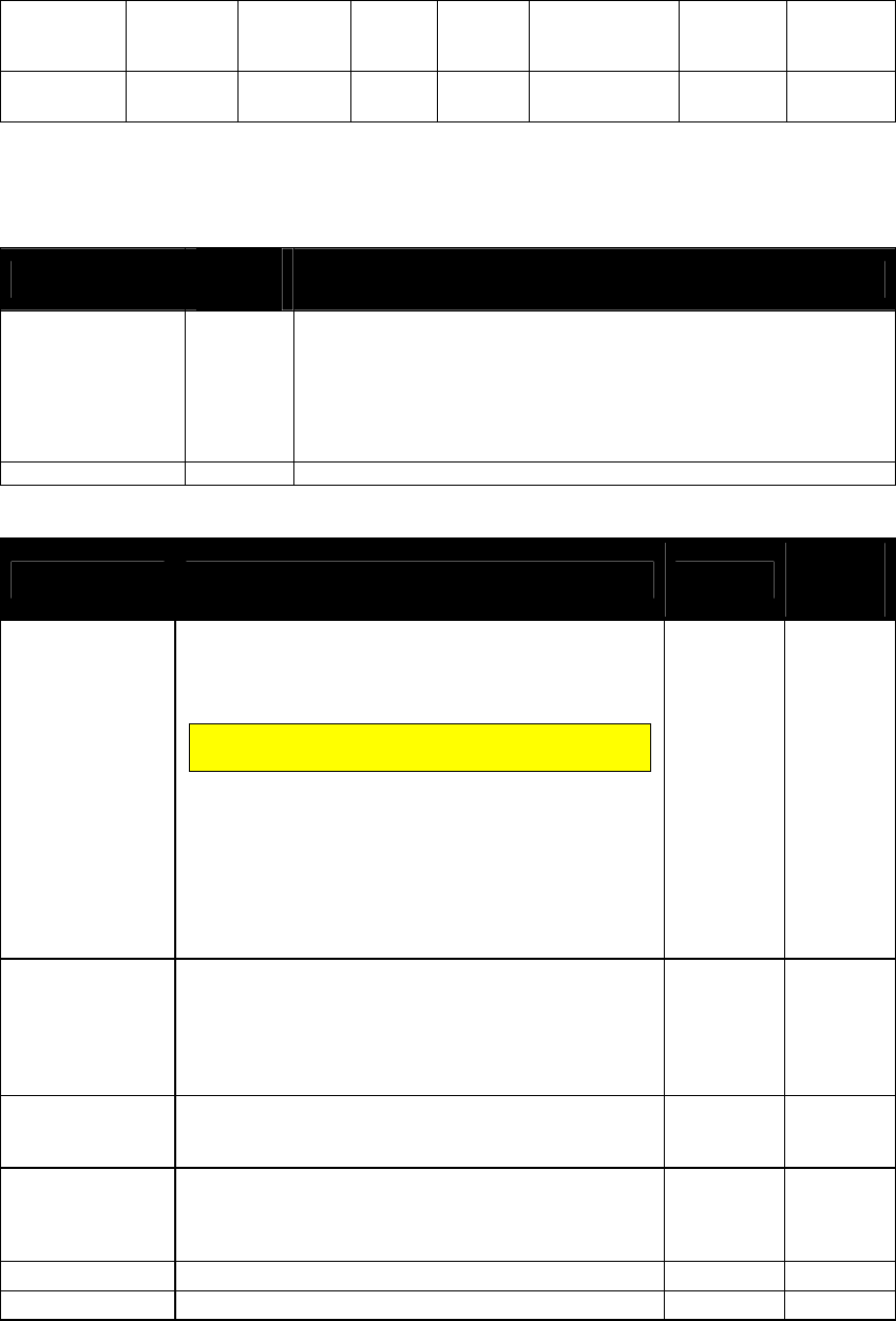
NEO Interface Developers Guide
179
Header Tag
& Protocol
Version
Command
Sub-
Command
Data
Length
(MSB)
Data
Length
(LSB)
Data CRC
(LSB)
CRC
(MSB)
ViVOtech2\0
02h 01h
See Data
Format below
The format and contents of the data field in the Command Frame are given in the following
table. All length values include the Tag and Length bytes.
Table 32: Activate Transaction Command Frame Data Format
Data Item Length
(bytes) Description
Timeout
1
Time in seconds that the reader waits for a card to be presented
before timing out and returning an Error response. The reader will
continue to poll for this amount of time if no card is found. Note
that if a card is found, the transaction may not complete within the
timeout period.
This field must be present in the Activate Command.
Format: Binary
TLV Data
varies
See Activate Command TLVs below.
Table 33: Activate Command TLVs
Tag Description Format Length
(in bytes)
9A
Transaction Date.
EMV data element. Local date that the transaction was
authorized. If TLV 9A and 9F21 are not provided, then
the reader’s current date and time will be used.
Both date (9A) and time (9F21) tags must be present
if either one is specified.
The terminal/POS is responsible for ensuring that the
date is valid:
Year <=99
Month <=12
Day <=31
If the date value is set to 0xFF, 0xFF, 0xFF, then the
date and time stamp will be taken from the reader’s
date and time will be used.
n6
(YYMMDD)
3
9C
Transaction Type.
Indicates the type of financial transaction, represented
by the first two digits of ISO 8583:1993 Processing
Code:
0x00 – Purchase Goods/Services
0x20 – Refund
n2 1
5F2A
Transaction Currency Code.
Indicates the currency code of the transaction, in
accordance with ISO 4217.
n3 2
5F36
Transaction Currency Exponent
Indicates the implied position of the decimal point from
the right of the transaction amount, according to ISO
4217.
n1 1
9F02
Amount, Authorized
n12
6
9F03
Amount Other
n12
6
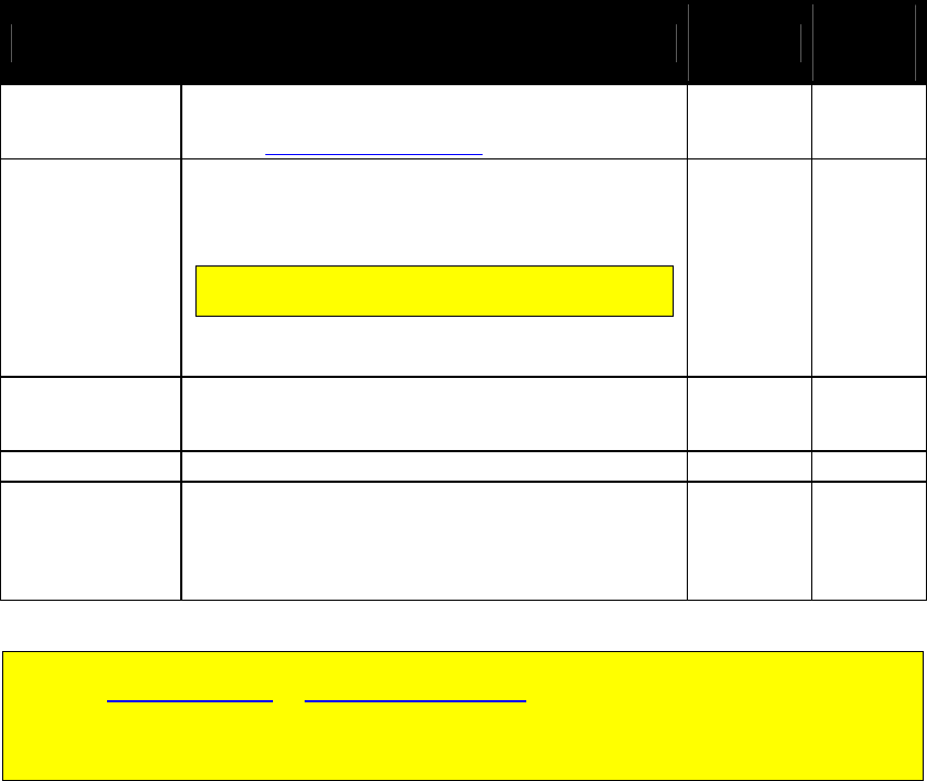
NEO Interface Developers Guide
180
Tag Description Format Length
(in bytes)
9F1A
Terminal Country Code.
(Typically, this has been configured in the reader –
refer to Group Configuration Tags.)
n3 2
9F21
Transaction Time.
Local time that the transaction was authorized. If TLV
9A and 9F21 are not provided, then the reader’s
current date and time will be used.
Both date (9A) and time (9F21) tags must be present
if either one is specified.
The terminal/POS is responsible for ensuring that the
time is valid.
n6
(HHMMSS) 3
9F5A
Terminal Transaction Type (Interac)
0x00 = Purchase
0x01 = Refund
b 1
FFEE01
ViVOtech TLV Group Tag
b
variable
DFEF7A
Determine ApplePay or AndroidPay transactions
(Vendi Used only.)
If vaule set to 1, After reading the card, the output
data will show tag DFEF7B to indicate whether it is
apple pay or android pay.
b 1
For EMV transactions, if the terminal has already set up one or more of these data items
using the Set Configuration or Set Configurable Group command, then the terminal need not
include those data items in the Command Frame. If the terminal includes one or more values
in the Command Frame, the reader uses the included values. If it does not, the reader just
uses the default or previously set values.
The ViVOpay reader starts polling for cards when it receives this command. If it finds a card, it
tries to complete a transaction with the card. If the card is a supported contactless EMV Card
the reader uses the TLV fields in the Command Frame for the transactions. If the card is a
contactless MagStripe Card, the reader does not use the TLV objects for the transaction.
If the transaction is completed successfully, and the card supported contactless EMV, then the
reader returns the Clearing Record in the response data, otherwise, if the card does not support
contactless EMV i.e. it is a contactless MagStripe Card, the reader returns Track information in
the response data.
If the transaction cannot be completed successfully, the response contains an appropriate status
code. The Response Frame contains more error information in the data field, for certain status
codes.
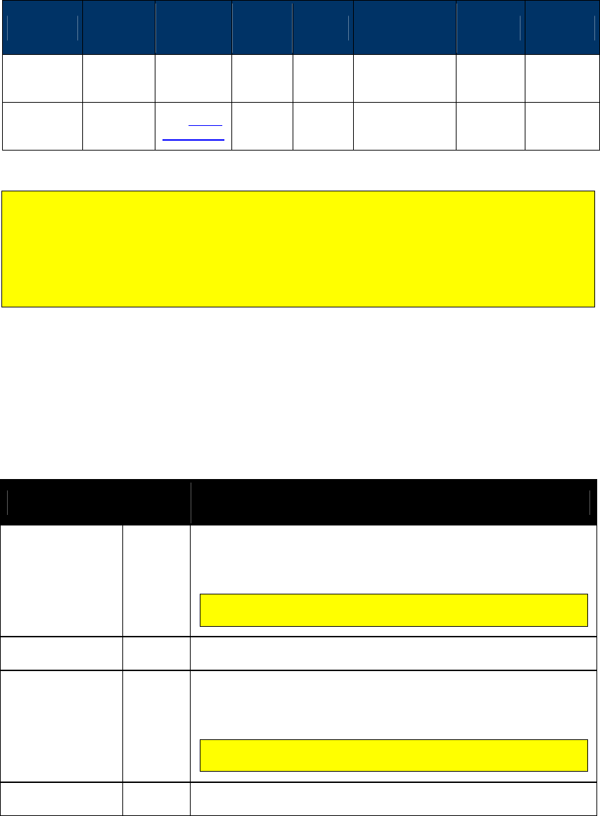
NEO Interface Developers Guide
181
Response Frame
Byte 0-9 Byte 10 Byte 11 Byte 12
Byte 13
Byte 14 …
Byte 14+n-1 Byte 14+n
Byte 15+n
Header Tag
& Protocol
Version
Command
Status Code
Data
Length
(MSB)
Data
Length
(LSB)
Data CRC
(MSB)
CRC
(LSB)
ViVOtech2\0
02h See Status
Code Table
See Response
Frame Data
Format
Note: Specific TLV data may or may not be returned based on what was recovered from the
card. Also, there is no implied sequence for returning the TLVs; the TLVs may or may not be
returned in the order listed in the table based on what was recovered from the card.
Note: ViVOcomm and DesFire cards return raw track data only.
Note: Kiosk III/ Vendi don't support ViVOcomm and DesFire cards.
If the Status Code is OK or “Request Online Authorization” then the format and contents of the
data field in the Response Frame are given in the following table.
Some data objects may not be present depending on the card involved in the transaction and
the presence or absence of a Clearing Record object (DE 055). All TLV lengths include the Tag
and Length bytes.
Table 34: Activate Transaction Response Frame Data Format: 02-01 Command (for 02-40,
see further below).
Data Item Length
(bytes) Description
Track 1 Length
1
If Track 1 is available, then this field gives the length of the Track 1
data that follows. If Track 1 is not available, then a Length of 00h is
returned.
Format: Binary
For MasterCard transactions, this field is always 0. If track data is
present, it is contained in the MasterCard TLVs.
Track 1 Data
(MagStripe Card)
Variable
Track 1 Data (if available).
Format: ASCII (no null terminator)
Track 2 Length
1
If Track 2 is available, then this field gives the length of the Track 2
data that follows. If Track 2 is not available, then a Length of 00h is
returned.
Format: Binary
For MasterCard transactions, this field is always 0. If track data is
present, it is contained in the MasterCard TLVs.
Track 2 Data
(MagStripe Card)
Variable
Track 2 Data (if available).
Format: ASCII (no null terminator)

NEO Interface Developers Guide
182
Data Item Length
(bytes) Description
DE055 (Clearing
Record) Present.)
1
If a Clearing Record (DE 055) field is available, then this field is 01h.
If there is no Clearing Record (DE 055) field, then this field is 00h.
For MasterCard transactions, this field is always 0.
TLV DE 055
(Clearing Record)
Variable
up to 128
DE 055 data (if available) as a TLV data object encoded with Tag ‘E1’.
The DE 055 data is the same data as is included in the Clearing
Record. Refer to the Activate Transaction Clearing Record table.
Tag: E1 Format: b1...126 variables.
TLV Data
Variable
See Activate Response TLVs below.
Not all of the tags will be present.
MasterCard transactions do not return a Clearing Record or the track data fields. Tags are
returned in a format specified by M/Chip 3.0. Track 1 and Track2 data are encapsulated in
tags according to the MasterCard specification.
Table 35: Activate Transaction Response TLVs
Tag Description Format Length
(in bytes)
50
Application Label.
Name associated with the AID, in accordance with
ISO/IEC 7816-5.
an <= 16
56
Track 1 Equivalent Data.
Contains the data objects of the track 1 according to
[ISO/IEC 7813] Structure B, excluding start sentinel, end
sentinel and LRC. The Track 1 Data may be present in
the file read using the READ RECORD command during a
mag-stripe mode transaction.
ans <=79
57
Track 2 Equivalent Data.
Contains the data objects of the track 2, in accordance
with ISO/IEC 7813, excluding start sentinel, end
sentinel, and LRC.
b <=19
5A
Application Primary Account Number (PAN).
The cardholder account number. cn
<=19
(10 bytes)
82
Application Interchange Profile.
Indicates the capabilities of the Card to support specific
functions in the application.
b 2
84
DF Name.
Identifies the name of the DF as described in ISO/IEC
7816-4.
b 5..16
95
Terminal Verification Results.
Status of various functions from the terminal
perspective.
b 5
99
Online PIN Block
n
16
9A
Transaction Date.
Local date that the transaction was performed.
n6
(YYMMDD) 3
9B
Transaction Status Information.
b
2

NEO Interface Developers Guide
183
Tag Description Format Length
(in bytes)
9C
Transaction Type.
Indicates the type of financial transaction, represented
by the first two digits of ISO 8583:1993 Processing Code.
n2 1
5F20
Cardholder Name.
b
<=26
5F24
Application Expiration Date.
The date after which the card application has expired.
n6
(YYMMDD)
3
5F25
Application Effective Date.
Date from which the card application may be used.
n6
(YYMMDD) 3
5F2A
Transaction Currency Code.
Indicates the currency code of the transaction, in
accordance with ISO 4217.
n3 2
5F2D
Language Preference.
1-4 languages stored in order of preference, each
represented by 2 alphabetical characters according to
ISO 639.
an 2..8
5F34
PAN Sequence Number.
Identifies and differentiates cards with the same
Application PAN.
n2 (BCD) 1
9F02
Amount, Authorized
n12
6
9F03
Amount Other
n12
6
9F06
Application Identifier (AID).
b
5..16
9F07
Application Usage Control.
b
2
9F09
Application Version Number (Reader)
Version number assigned by the payment system for the
Kernel application.
b 2
9F0D
Issuer Action Code (Default).
b
5
9F0E
Issuer Action Code (Denial).
b
5
9F0F
Issuer Action Code (Online).
b
5
9F10
Issuer Application Data.
Contains proprietary application data for transmission to
the issuer in an online transaction.
b <=32
9F11
Issuer Code Table Index.
Indicates the code table according to ISO/IEC 8859 for
displaying the Application Preferred Name.
n2 1
9F12
Application Preferred Name.
The preferred mnemonic associated with the AID. ans <=16
9F1A
Terminal Country Code.
(Typically, this has been configured in the reader – refer
to Group Configuration Tags.)
n3 2
9F1E
Interface Device Serial Number.
Unique and permanent serial number assigned to the IFD
by the manufacturer. (Typically, this has been
configured in the reader – refer to Group Configuration
Tags.)
an 8
9F21
Transaction Time.
Local time that the transaction was performed.
n6
(HHMMSS) 3
9F26
Application Cryptogram.
This is returned in the response to GenAC or RecoverAC. b 8

NEO Interface Developers Guide
184
Tag Description Format Length
(in bytes)
9F27
Cryptogram Information Data
Indicates the type of cryptogram and the actions to be
performed
.
b 1
9F33
Terminal Capabilities.
Indicates the card data input, CVM, and security
capabilities of the Terminal and Reader.
b 3
9F34
Cardholder Verification Method (CVM) Results.
Indicates result of last CVM performed. b 3
9F35
Terminal Type.
(Typically, this has been configured in the reader – refer
to Group Configuration Tags.)
n2 1
9F36
Application Transaction Counter.
Counter maintained by the application in the card. b 2
9F37
Unpredictable Number.
A challenge number used by the card to ensure
uniqueness of the generated cryptogram.
b 4
9F39
Point of Service (POS) Entry Mode. Indicates the method
by which the PAN was entered.
Values:
90h = Magnetic Stripe Reader Swipe
91h = Contactless MSD
05h = Contact EMV
07h = Contactless EMV
80h = Contact Fallback to Magnetic Stripe
n2 1
9F42
Application Currency Code.
Indicates the currency in which the account is managed
in accordance with ISO 4217.
n3 2
9F45
Data Authentication Code.
b
2
9F4C
ICC Dynamic Number.
b
8
9F53
Transaction Category Code.
Indicates the type of transaction being performed, and
which may be used in card risk management.
an 1
9F5A
Membership Scheme - Account Number (Amex)
Or
Terminal Transaction Type (Interac)
an
b
<=5
1
9F5B
Membership Scheme Number of Points (Amex).
an
<=29
Issuer Script Result(UICS)
b
<=128
9F5D
Available Offline Spending Amount (Balance).
b
6
9F6B
Track 2 Data.
Contains the data objects of the track 2 according to
ISO/IEC 7813, excluding start sentinel, end sentinel and
LRC.
b <=19
9F6C
Card Transaction Qualifiers (Visa transactions only). If
card does not return this tag then a length of zero is
returned.
b 16
9F6D
Mag-Stripe Application Version Number (Reader).
Version number assigned by the payment system for the
specific mag-stripe mode functionality of the Kernel.
b 2

NEO Interface Developers Guide
185
Tag Description Format Length
(in bytes)
9F6E
Third Party Data.
Contains various information, possibly including
information from a third party.
b 5..32
9F74
VLP Issuer Authorization
b
6
E300
Authorization Code.
b
8
DF8104
Balance Read Before GenAC. (MasterCard)
Balance read from the card before the GenAC. n12 6
DF8105
Balance Read After GenAC. (MasterCard)
Balance read from the card after the GenAC.
n12 6
DF8115
Error Indication. (MasterCard)
Flags defining the error conditions from the transaction.
Refer to the M/Chip PayPass specification.
b 6
DF8129
Outcome Parameter Set (MasterCard).
Contains the result of the transaction. Refer to the
M/Chip PayPass specification.
b 8
FF8105
Data Record (MasterCard, container).
Contains the data from the transaction. Refer to the
M/Chip PayPass specification.
b varies
FF8106
Discretionary Data (MasterCard, container).
Contains the discretionary data from the transaction.
Refer to the M/Chip PayPass specification.
b varies
FFEE01
ViVOPay Group Tag. (container)
This three-byte Group Tag was created to contain
ViVOpay proprietary Tags. See tags below.
b <=76
DF30
(ViVOpay
proprietary)
Track Data Source.
This tag is embedded in the ViVOpay Group tag. It
specifies whether the track data came from a swipe or
RFID transaction.
0Ch for swiped MagStripe
00h for a contactless card.
b 1
DF31
(ViVOpay
proprietary)
DD Card Track 1 (MagStripe Card)
This tag is embedded in the ViVOpay Group tag. If Track
1 Data is present, then DD CARD TRACK1 contains a copy
of the discretionary data field of Track 1 Data as
returned by the card.
b <= 56
DF32
(ViVOpay
proprietary)
DD Card Track 2 (MagStripe Card)
This tag is embedded in the ViVOpay Group tag. If Track
2 Data is present, then DD CARD TRACK2 contains a copy
of the discretionary data field of Track 2 Data as
returned by the card.
b <=8
DF33
(ViVOpay
proprietary)
Receipt Requirement (Interac)
This tag is embedded in the ViVOpay Group tag for
Interac transaction responses.
00 = No receipt required
01 = Receipt required
b 1
DF5B
(ViVOpay
proprietary
Terminal Entry Capability (Visa).
For Visa Transactions, defines reader support for VSDC
contact chip.
Values:
05h = Reader supports VSDC contact chip
08h = Reader does not support VSDC contact chip
n2 1
NEO Interface Developers Guide
186
Tag Description Format Length
(in bytes)
DFEE26
Encrypt Information
Length: 1 bytes
Values (same as Attribution):
Bit 4/3/0: Captured Data Type
0 0 0 = Contact Card
0 0 1 = Contactless Card / EMV
1 0 1 = Contactless Card / MSD
0 1 x = MSR Card
Bit 2/1: Encryption Mode
0 0 = TDES
0 1 = AES
Bit 6/5: Reserved
Bit 7: Encryption Status
0 = Encryption OFF
1 = Encryption ON
b 1
DFEF73
CUP Output Message Info (CUP)
Byte 1
b8
b7
b6
b5
b4
b3
b2
b1
-
-
-
-
-
-
-
X
Authorisation Message
-
-
-
-
-
-
X
-
Confirm Message
-
-
-
-
-
X
-
-
Reversal Message
-
X
X
X
X
-
-
-
Terminal Floor Limit Check
X
-
-
-
-
-
-
-
Date Exprired
b 1
DFEF7B
(Vendi Used Only)
If tag DFEF7A vaule set to 1, After reading the card, the
output data will show tag DFEF7B to indicate whether it
is apple pay or android pay.
If tag DFEF7A not set, output data will not output the
tag.
0 = Not Apple Pay/ Apple VAS or Android Pay/ Android
VAS
1 = Apple Pay or Apple VAS
2 = Android Pay or Android VAS
b 1
If a Clearing Record is returned, its potential TLVs are described in the following table.
Different card applications may have a slightly different format, or different TLVs, for the
Clearing Record. MasterCard M/Chip 3.0 does not return a clearing record.
Table 36: Activate Transaction Clearing Record TLVs
Tag
Data Element Name
Format
Origin
E1
DE 055
b1...126 var
50
Application Label
ans1…16 var
Card
82
Application Interchange Profile
b2
Card
84
DF name
b
Card
95
Terminal Verification Results:
Indicates results of various transaction processes.
b 5
Reader

NEO Interface Developers Guide
187
Tag
Data Element Name
Format
Origin
9A
Transaction Date
n6
Terminal
9B
Transaction Status Information
b2
Terminal
9C
Transaction Type
0x00 = Purchase Goods/Services
0x20 = refund
n2
Reader
5F2A
Transaction Currency Code
n3
Terminal
5F2D
Language Preference
an2-8 var
Card
5F34
Application Primary Account Number Sequence Number
n2
Card
9F02
Amount, Authorized (Numeric)
n12
Terminal
9F03
Amount, Other (Numeric, Visa only)
n12
Terminal
9F08
Application Version Number
b2
Card
9F09
Application Version Number
b2
Card
9F10
Issuer Application Data
b1-32 var
Card
9F11
Issuer Code Table Index
n2
Card
9F12
Application Preferred Name
ans1-16 var
Card
9F1A
Terminal Country Code
n3
Terminal
9F21
Transaction Time
n6
Terminal
9F26
Application Cryptogram
b8
Card
9F27
Cryptogram Information Data
b1
Card
9F33
Terminal Capabilities
b3
Terminal
9F34
Cardholder Verification Method (CVM) Results
b3
Terminal
9F35
Terminal Type (Interac)
b1
Terminal
9F36
Application Transaction Counter
b2
Card
9F37
Unpredictable Number
b4
Reader
9F39
POS Entry Mode
b1
Reader
9F45
Data Authentication Code
b2
Card
9F4C
ICC Dynamic Number
b2-8 var
Card
9F59
Terminal Transaction Information (Interac)
b3
Terminal
9F5A
Terminal Transaction Type (Interac)
b1
Terminal
9F66
Visa TTQ
b4
Reader
9F6C
Card Transaction Qualifiers (Visa only)
b2
Card
9F6E
Form Factor Indicator
or
PayPass Third Party Data
b4
b5-32 var
Reader
Reader
9F74
VLP Issuer Authentication Code
b
Terminal
9F7C
Customer Exclusive Data
b1-32 var
Reader
DF30
Track Data Source
0x0C – swiped mag-stripe card
0x00 – contactless card
b1
Reader
DF33
Receipt Required (Interac) – calculated by checking the
Interac Terminal Receipt Required Limit (9F5F).
b1
Reader
DF52
Transaction CVM:
00 = for No CVM
01 = for Signature
02 = for Online PIN
03 = for Mobile CVM / Consumer Device CVM
b1
Reader
DF76
TVR Backup – value of TVR prior to GenAC
b5
Reader
NEO Interface Developers Guide
188
Tag
Data Element Name
Format
Origin
FFEE01
ViVOpay Proprietary Group Tag
b variable
Terminal
If the Status Code being returned in the Response Frame is “Failed” and the Error Code is not
“Request Online Authorization”, then the contents of the Data field contains further information
on the cause of the failure and does not contain the Track or Clearing Record information. In
this case the Data field in the Response Frame has the following format.
Table 37: Activate Transaction Cause of Failure When Not Requesting Online Authorization
Data Field
Length
(bytes)
Description
Error Code
1
Error Code giving the reason for the failure. See sub-section on
Error Codes
SW1
1
Value of SW1 returned by the Card (SW1SW2 is 0000 if SW1 SW2
not available)
SW2
1
Value of SW2 returned by the Card (SW1SW2 is 0000 if SW1 SW2
not available)
RF State Code
1
RF State Code indicating exactly where the error occurred in
the Reader-Card transaction flow. See sub-section on RF State
Codes.
If the Status Code being returned in the Response Frame is “Failed” and the Error Code is
“Request Online Authorization”, then the contents of the Data field contains further information
on the cause of the failure and does not contain the Track or Clearing Record information. In
this case the Data field in the Response Frame has the following format.
Table 38: Activate Transaction Cause of Failure When Requesting Online Authorization
Data Field Length (bytes) Description
Error Code
1
Error Code giving the reason for the failure. See sub-
section on Error Codes
SW1
1
Value of SW1 returned by the Card (SW1SW2 is 0000 if
SW1 SW2 not available)
SW2
1
Value of SW2 returned by the Card (SW1SW2 is 0000 if
SW1 SW2 not available)
RF State Code
1
RF State Code indicating exactly where the error occurred
in the Reader-Card transaction flow. See sub-section on
RF State Codes.
TLV Track 2
Equivalent Data
21 (including Tag &
Length)
Track 2 Equivalent Data as a TLV object.
Tag: 57 Format: b19
Amount Requested
6
Difference between the Terminal Contactless Transaction
Limit (FFF1) and Balance. Format: n12
If the Status Code is “User Interface Event” then the format and contents of the data field in
the Response Frame are given in the following table:
Data Item Length (bytes) Description
Transaction status
1
01: The reader detects the card and initiates the
transaction.
NEO Interface Developers Guide
189
For any other Status Code the data field is empty.
If the transaction failed, the Response Frame may have the following format. Invalid or
inappropriate cards may result in no Response Frame.
Table 39: Activate Transaction Response Frame Format, Failed Transaction: 02-01 Command
(for 02-40, see further below)
Data Item Length
(bytes) Description
Error Code
1
Error Code giving the reason for the failure. See sub-section on
Error Codes
SW1
1
Value of SW1 returned by the Card (SW1SW2 is 0000 if SW1 SW2
not available)
SW2
1
Value of SW2 returned by the Card (SW1SW2 is 0000 if SW1 SW2
not available)
RF State Code
1
RF State Code indicating exactly where the error occurred in the
Reader-Card transaction flow. See RF State Codes.
TLV data
Varies
Refer to the Activate Response TLVs.
If the Status Code being returned in the Response Frame is "Request Online PIN", the reponse
data has the following format.
Data Item Length
(bytes) Description
TLV Application PAN
Variable
up to 12
Application Primary Account Number (PAN) as a TLV object.
Tag: 5A Format: cn variable length up to 19(10 bytes)
Special TLV for Discover D-PAS and SmartTap
A new ViVOtech proprietary tag “TLV Special Flow” will be added to the Activate Transaction command
data as shown below.
Command Data
Data Item
Length
(Bytes)
Description
:
:
:

NEO Interface Developers Guide
190
ViVOtech TLV
Group Tag
FFEE01
Variable
TLV
Special
Flow
2 Byte Tag +
1 Byte Length
+
Variable data
(max 40
bytes)
This TLV defines one or more special transaction
flows for specific non-payment process.
Tag: DF50
Format:
The TLV value contains one or more 4-byte
“Special Flow Record” entries. The format of a
Special Flow Record is given in the next table. A
Special Flow TLV cannot have more than 10
record entries.
TLV
Issuer
Script
2 Byte Tag +
n-Byte Length
+
Variable Data
This TLV is for Discover D-PAS only.
This TLV contains the Issuer Script that is to be
sent to the card. The Issuer Script is defined by
the Discover D-PAS specification.
Tag: DF51
Format: Raw data
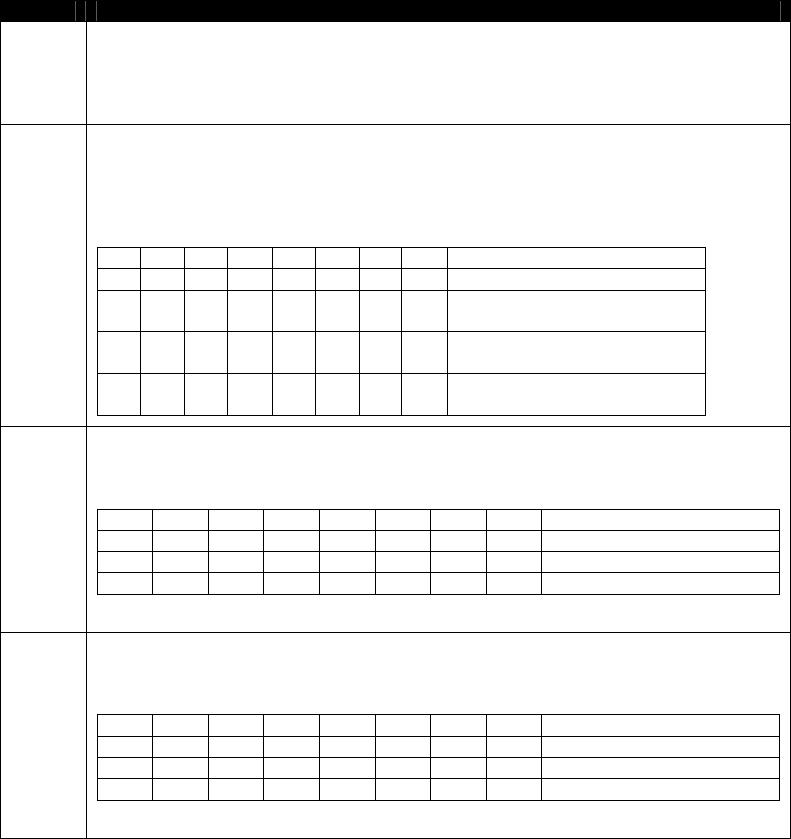
NEO Interface Developers Guide
191
Special Flow Record Format
Byte #
Field
1
Application Flow Code
This is the card application for which this special flow entry is being defined. This can
be any of the Application Flows defined for the ViVOtech2 “Set Configurable AID” such
as Discover D-PAS. This also can be any special Application Flow that not use
ViVOtech2 “Set Configurable AID” such as SmartTap.
2
Special Transaction Flow Flags
This byte defines the nature of the special flow and indicates whether the Application
Flow defined in the previous byte occurs during pre-PPSE or post-PPSE processing. It
also indicates whether a standard ISO Transaction will be performed in between pre-
PPSE and post-PPSE processing or skipped.
The flags within this byte are given below.
B7
B6
B5
B4
B3
B2
B1
B0
Flag Description
0
0
0
0
0
Unused. Set to 0
1
Perform
Post-PPSE Transaction
1
Perform
Pre-PPSE Transaction
1
Perform ISO Payment
Transaction (PPSE+AID)
3
Special Transaction Type Flags for Pre-PPSE Processing
This byte indicates the type of special (non-payment) transaction that will be
performed in the Pre-PPSE transaction processing (if any).
The flags within this byte are given below.
Bit7
Bit6
Bit5
Bit4
Bit3
Bit2
Bit1
Bit0
Flag Description
0
0
0
0
0
0
Unused. Set to 0
1
Write Transaction
1
Read Transaction
4
Special Transaction Type Flags for Post-PPSE Processing
This byte indicates the type of special (non-payment) transaction that will be
performed in the Post-PPSE transaction processing (if any).
The flags within this byte are given below.
Bit7
Bit6
Bit5
Bit4
Bit3
Bit2
Bit1
Bit0
Flag Description
0
0
0
0
0
0
Unused. Set to 0
1
Write Transaction
1
Read Transaction
Special Flow for Discover D-PAS
For Discover D-PAS, Application Flow Code is 14 (0Dh).
For Discover D-PAS 2nd Presentment of Issuer Update Process, the value in the Special Flow TLV will be:
Pre-PPSE Write D-PAS On-Line Script Processing DF50 04 0D 02 02 00
The 0xFFEE01 TLV format for Discover D-PAS when input Issuer Script for Issuer Update Processing:
FFEE01 <len> DF50 04 0D020200 DF51 <len> <Issuer Script>
<Issuer Script> is defined by D-PAS spec.
Steps to do Issuer Update Processing for Discover D-PAS:
Step1: Set TTQ Byte3 Bit8 “Issuer Update Processing supported” to be 1
Step2: Use “Activate Transaction Command (02-01)” to do normal Discover D-PAS transaction and reader
will response transaction result and data.
Step3: After host receives Online Request from reader, host can send “Activate Transaction Command (02-
01)” to reader with Issuer Scripts(DF51 TLV) in FFEE01 TLV. Then reader will run Issuer Update Processing
and response TVR and TSI
Special Flow for UICS

NEO Interface Developers Guide
192
For UICS, the special flow code ,Issuer Script format and usage is the same as D-PAS.
Special TLV for PayPass Application
This design connects the M/Chip signal handling to the existing GR user interface module (“Process D”) to
support MSG and OUT signals in ViVOpay readers with displays.
Reference files
[1] EMV Contactless Book C-2, Kernel 2 Specification, v2.3
[2] PayPass Test Cases for PayPass v3.0 Level 2 Reader Testing, Aug 2011
[3] EMV Contactless Specifications for Payment Systems, Book A, Architecture and General
Requirements, v2.3
[4] PayPass M/Chip Reader Card Application Interface Specification v3.0.2
[5] Engineering Specification, MChip 3.0 on GR, v1.6
(1) MSG Signals
MSG Signals are used by other processes to send the User Interface Request Data to Process D. Process D
manages the User Interface Requests as defined in reference [3] and displays a message and/or a status.
The User Interface Request Data is defined in reference [1] as tag DF8116 and holds twenty-two bytes of
data as shown in the table below:
Data Field
Length
Message Identifier
1
Status
1
Hold Time
3
Language Preference
8
Value Qualifier
1
Value
6
Currency Code
2
(2) OUT Signals
OUT Signals are used by the kernel (Process K) to indicate the outcome of a transaction.
According to reference [1] the OUT signal may comprise the following objects.
Data Field
Tag
Length
Outcome Parameter Set
DF8129
8
Data Record (if any)
FF8105
var.
Discretionary Data
FF8106
var.
User Interface Request Data (if any)
DF8116
22
According to reference [1], all objects listed below are to be added to the output buffer if they are present.
The Data Record (FF8105) may contain the following objects for an EMV transaction, with a maximum length
of 256 bytes (74 TL, 182 V).
Data Field
Tag
Length
Amount, Authorized (Numeric)
9F02
6
Amount, Other (Numeric)
9F03
6
Application Cryptogram
9F26
8
Application Expiration Date
5F24
3
Application Interchange Profile
82
2
Application Label
50
16
Application PAN
5A
16
Application PAN Sequence Number
5F34
1
Application Preferred Name
9F12
16
Application Transaction Counter
9F36
2

NEO Interface Developers Guide
193
Application Version Number (Reader)
9F08
2
Cryptogram Information Data
9F27
1
CVM Results
9F34
3
DF Name
84
16
Interface Device Serial Number
9F1E
8
Issuer Application Data
9F10
32
Issuer Code Table Index
9F11
1
Terminal Capabilities
9F33
3
Terminal Country Code
9F1A
2
Terminal Type
9F35
1
Terminal Verification Results
95
5
Track 2 Equivalent Data
57
19
Transaction Category Code
9F53
1
Transaction Currency Code
5F2A
2
Transaction Date
9A
3
Transaction Type
9F21
3
Unpredictable Number
9F37
4
The Data Record may contain the following objects for a Mag-Stripe transaction, with a possible maximum
length of 182 bytes (20 TL, 162 V).
Data Field
Tag
Length
Application Label
50
16
Application PAN
5A
16
Application Preferred Name
9F12
16
Mag-stripe Application Version Number
9F6D
2
DF Name
84
16
Issuer Code Table Index
9F11
1
Track 1 Data
56
76
Track 2 Data
9F6B
19
Discretionary Data is always included in an OUT signal. Discretionary Data for an EMV transaction may
include the following objects, with a possible maximum length of 1009 bytes (61 TL, 948 V), ignoring the Data
Storage elements. Without the Torn Record maximum size would only be 80 bytes.
FF8106
var
Discretionary Data
9F42
2
Application Currency Code
DF8105
6
Bal Read After Gen AC
DF8104
6
Bal Read Before Gen AC
DS Summary 3
DS Summary Status
DF8115
6
Error Indication
DF810E
1
Post-Gen AC Put Data Status
DF8105
1
Pre-Gen AC Put Data Status
9F6E
32
Third Party Data
FF8101
894
Torn Record
A Torn Record (FF8101) contains the following objects and may have a maximum length of 894 bytes (66 TL,
828 V);
Data Field
Tag
Length
Amount, Authorized (Numeric)
9F02
6
Amount, Other (Numeric)
9F03
6
Application PAN
5A
16
Application PAN Sequence Number
5F34
1
Balance Read Before Gen AC
DF8104
6
CDOL1 Related Data
DF8107
252
CVM Results
9F34
3

NEO Interface Developers Guide
194
DRDOL Related Data
DF8113
252
IDS Status
DF8128
1
Interface Device Serial Number
9F1E
8
PDOL Related Data
DF8111
252
Reference Control Number
DF8114
1
Terminal Capabilities
9F33
3
Terminal Country Code
9F1A
2
Terminal Type
9F35
1
Terminal Verification Results
95
5
Transaction Category Code
9F53
1
Transaction Currency Code
5F2A
2
Transaction Date
9A
3
Transaction Type
9F21
3
Unpredictable Number
9F37
4
Discretionary Data for a Mag-Stripe transaction may include the following objects, with a possible maximum
length of 117 bytes (15 TL, 102 V):
FF8106
var
Discretionary Data
DF812A
56
DD Card (Track 1)
DF812B
8
DD Card (Track 2)
DF8115
6
Error Indication
9F6E
32
Third Party Data
The most typical Intermediate OUT Signal (for cases such as Error – Other Card and Try Again) are only
required to include the Outcome Parameter Set and the Error Indication and the L2 tests usually focus on
verifying data within these objects.
Tag
Len
Data Object
DF8129
8
Outcome Parameter Set
FF8106
10
Discretionary Data
DF8115
6
Error Indication
(3) Signal Data TLV – FFEE04
A new proprietary TLV is defined to hold the intermediate signal data during a transaction. It will be populated
with one or more signal objects as the UI_MSG_Signal function in UserInterface.c receives MSG Signals and
the UI_OUT_Signal function in UserInterface.c receives OUT Signals.
This tag must be included in the ACT command to enable the signal data capture feature during the
transaction. If it is received in the ACT command this feature is enabled and the Signal Data Handler will add
signal data to the buffer. If it is not received, the Signal Data Handler will do nothing and the length of this
TLV will remain 0 and nothing will be returned.
A second new proprietary tag is defined (FFEE05) which is used to separate and identify each individual
signal entry added to the buffer, whether it is a MSG signal or an OUT signal. A new tag (DF8914) which
includes Activate Response TLVs (Table 29) may be included in FFEE05.
When the transaction is complete, if tag FFEE04 was received in the ACT command and the Signal Data tag
is not empty, it will be added to the ACT response. The signal data buffer (the “contents” of FFEE04) is
cleared when an ACT command is received.
Activate Transaction Response Frame Data Format
For additional information on how data portions are encrypted, please see “80000502-001, ID
Tech Encrypted Data Output Formats” for details.
Mode/Transaction Output Format Matrix—NSRED Device Contactless card
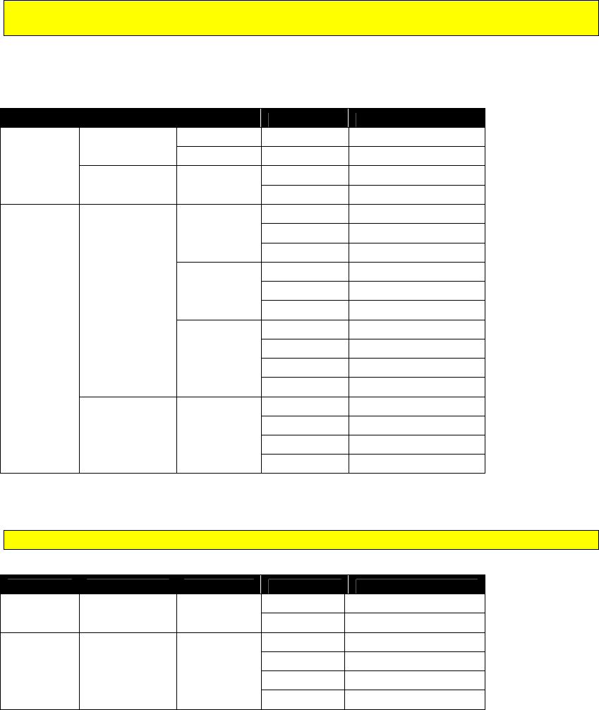
NEO Interface Developers Guide
195
Note: When MSR/MSD or EMV Encryption is enabled and Data encryption Key exists, Burst
Mode is disabled (always OFF)
When encryption is enabled and Data encryption Key exists, Encrypt Mode is ON.
Otherwise (encryption is disabled or Data encryption Key is absent), Encrypt Mode is OFF.
Poll Mode
Encrypt Mode
Burst Mode
Command
Output Format
Poll On
Demond
OFF
NA
02-01
02-01 plaintext
NA
02-40
02-40 plaintext
ON NA
02-01
Not Allow
02-40 02-40 encrypted
Auto Poll
OFF
ON
No Cmd Burst Format
02-01 Burst Format
02-40 Burst Format
AutoExit
No Cmd Burst Format
02-01
02-01 plaintext
02-40
02-40 plaintext
OFF
03-00
02-01 plaintext
02-01
02-01 plaintext
03-40 02-40 plaintext
02-40 02-40 plaintext
ON OFF
03-00 Not Allow
02-01 Not Allow
03-40 02-40 encrypted
02-40
02-40 encrypted
Mode/Transaction Output Format Matrix—SRED Device Contactless card
Note: For SRED device, encryption is always enabled and Burst Mode is disabled (always OFF)
Poll Mode Encrypt Mode Burst Mode Command Output Format
Poll On
Demond ON OFF 02-01 Not Allow
02-40 02-40 encrypted
Auto Poll ON ON
03-00 Not Allow
02-01 Not Allow
03-40
02-40 encrypted
02-40
02-40 encrypted
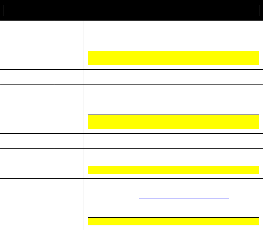
NEO Interface Developers Guide
196
Table 40: Success Transaction--Plaintext data field format (02-01)
Data Item Length
(bytes) Description
Track 1 Length
1
If Track 1 is available, then this field gives the length of the Track 1
data that follows. If Track 1 is not available, then a Length of 00h is
returned.
Format: Binary
For MasterCard transactions, this field is always 0. If track data is
present, it is contained in the MasterCard TLVs.
Track 1 Data
(MagStripe Card)
Variable
Track 1 Data (if available).
Format: ASCII (no null terminator)
Track 2 Length
1
If Track 2 is available, then this field gives the length of the Track 2
data that follows. If Track 2 is not available, then a Length of 00h is
returned.
Format: Binary
For MasterCard transactions, this field is always 0. If track data is
present, it is contained in the MasterCard TLVs.
Track 2 Data
(MagStripe Card)
Variable
Track 2 Data (if available).
Format: ASCII (no null terminator)
DE055 (Clearing
Record) Present.)
1
If a Clearing Record (DE 055) field is available, then this field is 01h.
If there is no Clearing Record (DE 055) field, then this field is 00h.
For MasterCard transactions, this field is always 0.
TLV DE 055
(Clearing Record)
Variable
up to 128
DE 055 data (if available) as a TLV data object encoded with Tag ‘E1’.
The DE 055 data is the same data as is included in the Clearing
Record. Refer to the Activate Transaction Clearing Record table.
Tag: E1 Format: b1...126 variables.
TLV Data
Variable
See Activate Response TLVs
Not all of the tags will be present.
Table 41: Successful Transaction -- Plaintext and Encrypted data field format for Contactless
card (02-40)

NEO Interface Developers Guide
197
Data Item Length
(bytes) Description
Attribution 1 Bit 4/3/0: Captured Data Type
0 0 0 = Contact Card
0 0 1 = Contactless Card / EMV
1 0 1 = Contactless Card / MSD
0 1 x = MSR Card
Bit 2/1: Encryption Mode
0 0 = TDES
0 1 = AES
1 x = Reserved
Bit 5: Reserved for Attribution Byte Extension.
Bit 6/7: Encryption Status
0 0 = MSR/MSD off, EMV off
0 1 = MSR/MSD off, EMV on
1 0 = MSR/MSD on, EMV off
1 1 = MSR/MSD on, EMV on
TLV KSN
(FFEE12)
Variable
KSN of DUKPT Account Key
Tag: FFEE12 Format: Binary
If encrypt disable or MSR data, this tag is not present.
TLV Track 1 Data
(MagStripe Card)
Variable
TDES/AES Encrypted Track 1 Data (if available) with Padding
(0x00). If Track 1 is not available, this field is not present.
Tag: FFEE13 Format: ASCII (no null terminator)
TLV Track 2 Data
(MagStripe Card)
Variable
TDES/AES Encrypted Track 2 Data (if available) with Padding
(0x00). If Track 2 is not available, this field is not present
Tag: FFEE14 Format: ASCII (no null terminator)
TLV DE 055
(Clearing Record)
Variable
up to 128
DE 055 data (if available) as a TLV data object encoded with Tag
‘E1’. The DE 055 data is the same data as is included in the Clearing
Record. Refer to the Activate Transaction Clearing Record table.
Sensitive TLV will be TDES/AES encrypted with Padding (0x00)
Please see “80000404-001 ID-Tech Encrypt Data Format In
Command Response Specification” for details
Tag: E1 Format: b1…126 variables.
TLV Data Variable
See Activate Response TLVs
Sensitive TLV will be TDES/AES encrypted with Padding (0x00)
Please see “80000404-001 ID-Tech Encrypt Data Format In
Command Response Specification” for details
Not all of the tags will be present.
For MasterCard transactions, this field is not present. If track
data is present, it is contained in the MasterCard TLVs.
For MasterCard transactions, this field is not present. If track
data is present, it is contained in the MasterCard TLVs.

NEO Interface Developers Guide
198
Table 42: Success Transaction -- Plaintext and Encrypted data field format for MSR card (02-
40)
Data Item Length
(bytes) Description
Attribution
1
Bit 4/3/0: Captured Data Type
0 0 0 = Contact Card
0 0 1 = Contactless Card / EMV
1 0 1 = Contactless Card / MSD
0 1 x = MSR Card
Bit 2/1: Encryption Mode
0 0 = TDES
0 1 = AES
Bit 6/5: Reserved
Bit 7: Encryption Status
0 = Encryption OFF
1 = Encryption ON
MSR TLV
Variable
MSR TLV
Data length compose of data length indicator (1 byte) and actual data length
byte.
MSR FIELD DATA length Data length
Indicator byte
Data length
byte
Data <128 bytes 01~7F X 1
128 bytes <= Data <=255 bytes 80~FF 81 1
Data > 255 bytes FF~ 82 2
Data is follow Enhanced Encrypted MSR FIELD DATA. Refer to Appendix A.11:
Enhanced Encrypted MSR Data Output Format
Tag: DFEE23 Format: Binary
TLV Data
Variable
See Activate Response TLVs
Table 43: Failed Transaction--Plaintext data field format (02-01)
Data Item Length
(bytes) Description
Error Code
1
Error Code giving the reason for the failure. See sub-section on
Error Codes
SW1
1
Value of SW1 returned by the Card (SW1SW2 is 0000 if SW1 SW2
not available)
SW2
1
Value of SW2 returned by the Card (SW1SW2 is 0000 if SW1 SW2
not available)
RF State Code
1
RF State Code indicating exactly where the error occurred in the
Reader-Card transaction flow. See RF State Codes.
TLV data
Varies
Refer to the Activate Response TLVs.

NEO Interface Developers Guide
199
Table 44: Failed Transaction-- Plaintext and Encrypted data field format (02-40)
Data Item Length
(bytes) Description
Attribution 1 Bit 4/3/0: Captured Data Type
0 0 0 = Contact Card
0 0 1 = Contactless Card / EMV
1 0 1 = Contactless Card / MSD
0 1 x = MSR Card
Bit 2/1: Encryption Mode
0 0 = TDES
0 1 = AES
1 x = Reserved
Bit 5: Reserved for Attribution Byte Extension.
Bit 6/7: Encryption Status
0 0 = MSR/MSD off, EMV off
0 1 = MSR/MSD off, EMV on
1 0 = MSR/MSD on, EMV off
1 1 = MSR/MSD on, EMV on
TLV KSN
(FFEE12)
Variable
KSN of DUKPT Account Key
Tag: FFEE12 Format: Binary
If encrypt disable or MSR data, this tag is not present.
TLV Contactless
Error Code Table
(FFEE1F)
Variable
Byte 1: Error Code.
(Error Code giving the reason for the failure.)
Byte 2: SW1
(Value of SW1 returned by the Card (SW1SW2 is 0000 if SW1
SW2 not available))
Byte 3: SW2
(Value of SW2 returned by the Card (SW1SW2 is 0000 if SW1
SW2 not available))
Byte 4: RF State Code
(RF State Code indicating exactly where the error occurred in the
Reader-Card transaction flow.)
TLV Data Variable
Refer to the Activate Response TLVs.
Sensitive TLV will be TDES/AES encrypted with Padding (0x00)
Please see “80000404-001 ID-Tech Encrypt Data Format In
Command Response Specification” for details

NEO Interface Developers Guide
200
Data Item Length
(bytes) Description
Attribution 1 Bit 4/3/0: Captured Data Type
0 0 0 = Contact Card
0 0 1 = Contactless Card / EMV
1 0 1 = Contactless Card / MSD
0 1 x = MSR Card
Bit 2/1: Encryption Mode
0 0 = TDES
0 1 = AES
1 x = Reserved
Bit 5: Reserved for Attribution Byte Extension.
Bit 6/7: Encryption Status
0 0 = MSR/MSD off, EMV off
0 1 = MSR/MSD off, EMV on
1 0 = MSR/MSD on, EMV off
1 1 = MSR/MSD on, EMV on
TLV KSN
(FFEE12)
Variable
KSN of DUKPT Account Key
Tag: FFEE12 Format: Binary
If encrypt disable or MSR data, this tag is not present.
TLV Contactless
Error Code Table
(FFEE1F)
Variable
Byte 1: Error Code.
(Error Code giving the reason for the failure.)
Byte 2: SW1
(Value of SW1 returned by the Card (SW1SW2 is 0000 if SW1
SW2 not available))
Byte 3: SW2
(Value of SW2 returned by the Card (SW1SW2 is 0000 if SW1
SW2 not available))
Byte 4: RF State Code
(RF State Code indicating exactly where the error occurred in the
Reader-Card transaction flow.)
TLV Data Variable
Refer to the Activate Response TLVs.
Sensitive TLV will be TDES/AES encrypted with Padding (0x00)
Please see “80000404-001 ID-Tech Encrypt Data Format In
Command Response Specification” for details
Continue Transaction for Cardholder Verification (02-07)
Use this command to send the result of Online PIN Request and to continue a contactless UICS
transaction. If the prior response Status Code is 31h(Request Online PIN), this is the next
command to send. This command is now used for CUP brand only.
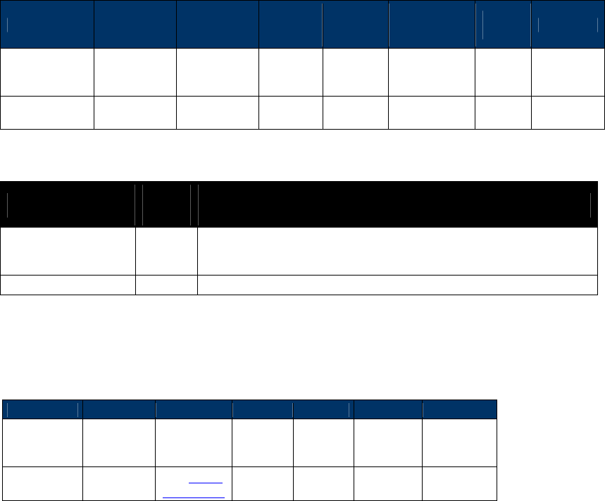
NEO Interface Developers Guide
201
Command Frame
Byte 0-9 Byte 10 Byte 11 Byte 12
Byte 13
Byte
14 ...Byte
14+n-1
Byte
14+n Byte 15+n
Header Tag &
Protocol
Version
Command Sub-
Command
Data
Length
(MSB)
Data
Length
(LSB)
Data CRC
(LSB) CRC (MSB)
ViVOtech2\0 02h 07h 00h 00h
See Data
Table
The format and contents of the data field are as below:
Data Item Length
(bytes) Description
Result
1
Mandatory
00h: Request Online PIN
Other: Cancelled PIN Request
Encrypted PIN Block
16
Mandatory if Result is 00h for Online PIN
Note: After Online Response, if the (02-07) command is not received for 60s, get Online PIN will
timeout.
Response Frame
Byte 0-9
Byte 10
Byte 11
Byte 12
Byte 13
Byte 14+n
Byte 15+n
Header Tag
& Protocol
Version
Command
Status Code
Data
Length
(MSB)
Data
Length
(LSB)
CRC (MSB)
CRC
(LSB)
ViVOtech2\0
02h
See Status
Code Table

NEO Interface Developers Guide
202
Get Transaction Result (03-00 and 03-40)
NOTE: 03-00 is a legacy command, applicable to non-encrypted transactions only.When EMV
encryption ON or MSR/MSD encryption ON, if Data encryption Key is loaded, 03-00 will be
disabled. 03-40 is a unified command for both non-encrypted and encrypted transaction.
Use this command when the ViVOpay reader is functioning in “Auto Poll” mode. In this mode the
reader does not wait for an Activate Transaction command to start polling for a card. It is
always in Auto Poll Mode. When it detects a card, it carries out a transaction with the card. If
the card is a supported contactless MagStripe card, the reader does not need any parameters
from the terminal. If the card is a supported contactless EMV Card, then the reader uses the
default terminal parameters (Group 0 TLVs) in the reader. If some terminal parameters had
been set by using the Set Configuration command, then the reader uses the new values for these
parameters.
If the transaction is successful, the reader keeps the transaction data (Track or Clearing Record)
in its memory. When it receives the Get Transaction Result command, it returns this data to the
terminal immediately and reset its data buffer. If the reader has not detected any card since
power up or since the last Get Transaction Result command, and this command is received, the
reader responds back immediately indicating that it has no data for the terminal.
In Auto Poll Mode the reader can carry out only contactless MagStripe and contactless EMV
transactions. It cannot carry out any ticketing or ePurse transactions since these transactions
require interaction with the Terminal during the transaction itself.
Note: For Non-SRED version device, response format for Activate Transaction Command is
according to “Set Data Encryption Enable Flag (C7-36)” setting and Data encryption Key.
When Data Encryption is disabled, device responds with plaintext data format. When Data
Encryption is enabled: (1) When Data encryption Key exists and is valid, device responds with
encrypted data format. (2) When Data encryption Key does not exist, device responds with
plaintext data format (3) When Data encryption Key exhausts, device responds status code
0x91 and no data.
For SRED version device, response format for Activate Transaction Command is according to
Data encryption Key. When Data encryption Key exists and is valid, device responds with
encrypted data format. When Data encryption Key exhausts or does not exist, device
responds status code 0x91/0x90 and no data.
Command Frame
Byte 0-9
Byte 10
Byte 11
Byte 12
Byte 13
Byte 14
Byte 15
Header Tag &
Protocol
Version
Command Sub-
Command
Data
Length
(MSB)
Data
Length
(LSB)
CRC (LSB) CRC (MSB)
ViVOtech2\0
03h
00h
00h
00h
On receiving this command, the ViVOpay reader returns one of the following.
A response containing Track Data (Contactless MagStripe Transaction)

NEO Interface Developers Guide
203
A response containing a Clearing Record (Contactless EMV Transaction)
A response containing no Data (No transaction)
If the transaction cannot be completed successfully, the response indicates an OK status and
indicates “No Data”.
Note: ViVOcomm and DesFire cards return raw track data only.
If there was an error in the Command Frame received then the response contains an appropriate
status code.
Response Frame
Byte 0-9 Byte 10 Byte 11 Byte 12
Byte 13
Byte 14 …
Byte 14+n-1 Byte 14+n
Byte 15+n
Header Tag
& Protocol
Version
Command
Status Code
Data
Length
(MSB)
Data
Length
(LSB)
Data CRC (MSB)
CRC
(LSB)
ViVOtech2\0
03h
See Status
Code Table
See Data Tables
If Status Code is OK, then the format and contents of the data field in the Response Frame are
given in the following table. Some data objects may not be present depending on the card
involved in the transaction and the presence or absence of a Clearing Record object (DE 055).
All TLV lengths include the Tag and Length bytes.
Table 45: Get Transaction Result Format and Content: Plaintext data field format (03-00)
Data Item Length
(bytes) Description
Track 1 Length
1
If Track 1 is available, then this field gives the length of the Track 1
data that follows. If Track 1 is not available, then a Length of 00h is
returned.
Format: Binary
Track 1 Data
(MagStripe card)
Variable
Track 1 Data (if available).
Format: ASCII (no null terminator)
Track 2 Length
1
If Track 2 is available, then this field gives the length of the Track 2
data that follows. If Track 2 is not available, then a Length of 00h is
returned.
Format: Binary
Track 2 Data
(MagStripe card)
Variable
Track 2 Data (if available).
Format: ASCII (no null terminator)
DE055 (Clearing
Record) Present
1
If a Clearing Record (DE 055) field is available, then this field is 01h.
If there is no Clearing Record (DE 055) field, then this field is 00h.
TLV DE 055
(Clearing Record)
(see Clearing
Record Format)
Variable
up to 128
DE 055 data (if available) as a TLV data object encoded with Tag
‘E1’. The DE 055 data is the same data as is included in the Activate
Transaction Clearing Record. Refer to the Activate Transaction
Clearing Record table.
Tag: E1 Format: b1...126 variable.

NEO Interface Developers Guide
204
Data Item Length
(bytes) Description
TLV Data
Variable
Refer to Activate Response TLVs.
If the Status Code is OK the response is different depending on the card application:
Card Application Return Data
PayPass MagStripe
Track1/Track2
PayPass M/Chip
Chip data plus other tags
JCB QuicPay
TLV Auth code and Track2 Equivalent data
VSDC online application
Track1/Trakc2 and VLP Issuer Auth code
VSDC offline and qVSDC
Chip data E1 and some other tags
A Status Code 23 (request online authorization) can be returned for some cards (qVSDC &
M/Chip) with a fully populated data field.
This command never returns a status code of “Failed”. If any status code other than OK or
status code ‘23’ (request online authorization) is returned, the data field is empty.
The above description is plaintext response. The encrypted data format is as follows: (Please
see “80000404-001 ID-Tech Encrypt Data Format In Command Response Specification” for details)
Table 46: Get Transaction Result format for contactless card: Plaintext and Encrypted data
field format (03-40)
Data Item Length
(bytes) Description
Attribution 1 Bit 4/3/0: Captured Data Type
0 0 0 = Contact Card
0 0 1 = Contactless Card / EMV
1 0 1 = Contactless Card / MSD
0 1 x = MSR Card
Bit 2/1: Encryption Mode
0 0 = TDES
0 1 = AES
1 x = Reserved
Bit 5: Reserved for Attribution Byte Extension.
Bit 6/7: Encryption Status
0 0 = MSR/MSD off, EMV off
0 1 = MSR/MSD off, EMV on
1 0 = MSR/MSD on, EMV off
1 1 = MSR/MSD on, EMV on
TLV KSN 10 If encrypt disable, this tag is not present.
KSN of DUKPT Account Key
Tag: FFEE12 Format: Binary
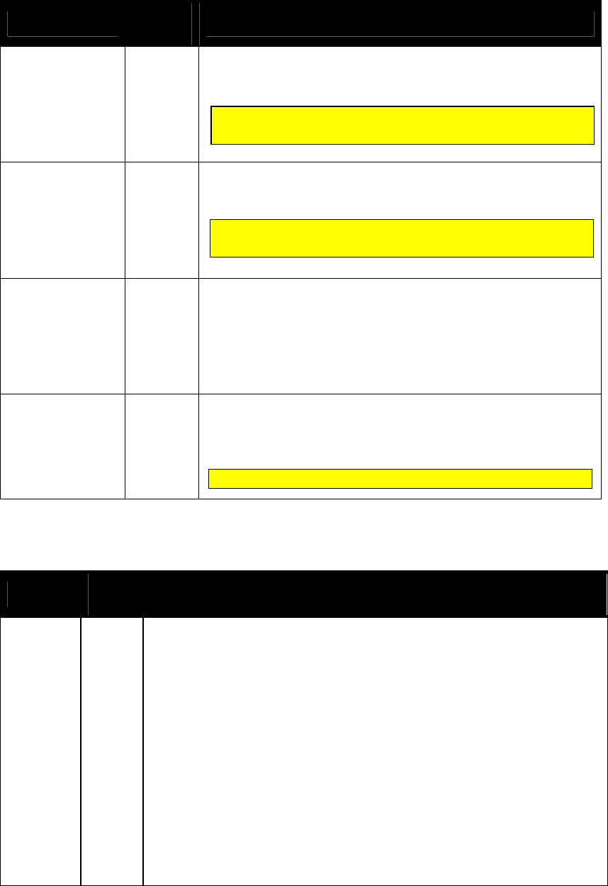
NEO Interface Developers Guide
205
Data Item Length
(bytes) Description
TLV Track 1 Data
(MagStripe card)
Variable TDES/AES Encrypted Track 1 Data (if available) with Padding
(0x00). If Track 1 is not available, this field is not present.
Tag: FFEE13 Format: ASCII (no null terminator)
TLV Track 2 Data
(MagStripe card)
Variable TDES/AES Encrypted Track 2 Data (if available) with Padding
(0x00). If Track 2 is not available, this field is not present
Tag: FFEE14 Format: ASCII (no null terminator)
TLV DE 055
(Clearing Record)
(see Clearing
Record Format)
Variable
up to 128
DE 055 data (if available) as a TLV data object encoded with Tag
‘E1’. The DE 055 data is the same data as is included in the Clearing
Record. Refer to the Activate Transaction Clearing Record table.
Sensitive TLV will be TDES/AES encrypted with Padding (0x00)
Please see “80000404-001 ID-Tech Encrypt Data Format In
Command Response Specification” for details
Tag: E1 Format: b1…126 variables.…
TLV Data Variable See Activate Response TLVs
Sensitive TLV will be TDES/AES encrypted with Padding (0x00)
Please see “80000404-001 ID-Tech Encrypt Data Format In
Command Response Specification” for details
Not all of the tags will be present.
Table 47: Get Transaction Result format for MSR card: Encrypted
Data Item Length
(bytes) Description
Attribution
1 Bit 4/3/0: Captured Data Type
0 0 0 = Contact Card
0 0 1 = Contactless Card / EMV
1 0 1 = Contactless Card / MSD
0 1 x = MSR Card
Bit 2/1: Encryption Mode
0 0 = TDES
0 1 = AES
1 x = Reserved
Bit 5: Reserved for Attribution Byte Extension.
Bit 6/7: Encryption Status
0 0 = MSR/MSD off, EMV off
0 1 = MSR/MSD off, EMV on
1 0 = MSR/MSD on, EMV off
1 1 = MSR/MSD on, EMV on
For MasterCard transactions, this field is not present. If track
data is present, it is contained in the MasterCard TLVs.
For MasterCard transactions, this field is not present. If track
data is present, it is contained in the MasterCard TLVs.

NEO Interface Developers Guide
206
Data Item Length
(bytes) Description
TLV
(DFEE25)
Variable
Response Code TLV
Tag: DFEE25 Format: Binary
Response: 00h 11h
TLV MSR
Data
(DFEE23)
Variable
Refer to “Enhanced Encrypted MSR Data Output Format” section of document
80000502-001, Encrypted Data Output Formats. This tag will wrap an entire
MSR data block.
Enhanced encrypted MSR FIELD DATA length Data length
Indicator byte
Data length
byte
Data <128 bytes 01~7F X 1
128 bytes <= Data <=255 bytes 80~FF 81 1
Data > 255 bytes FF~ 82 2
TLV Data Variable
TLV data list
TLV POS
Entry
Mode
(9F39)
Variable
90h = Magnetic Stripe Reader Swipe
91h = Contactless MSD
05h = Contact EMV
07h = Contactless EMV
80h = Contact Fallback to Magnetic Stripe
TLV
(DF30)
(ViVOpay
proprietary)
Variable
Track Data Source.
This tag is embedded in the ViVOpay Group tag. It specifies whether the track
data came from a swipe or RFID transaction.
0Ch for swiped MagStripe
00h for a contactless card.
01h for a contact card.
This tag include in ViVOpay proprietary (FFEE01)
Ex: FFEE0104DF30010C
TLV
Encrypt
Information
(DFEE26)
Variable
Encrypt Information.
Length: 1 byte
Values: Same as “Attribution” byte definition
Bit 4/3/0: Captured Data Type
0 0 0 = Contact Card
0 0 1 = Contactless Card / EMV
1 0 1 = Contactless Card / MSD
0 1 x = MSR Card
Bit 2/1: Encryption Mode
0 0 = TDES
0 1 = AES
1 x = Reserved
Bit 5: Reserved for Attribution Byte Extension.
Bit 6/7: Encryption Status
0 0 = MSR/MSD off, EMV off
0 1 = MSR/MSD off, EMV on
1 0 = MSR/MSD on, EMV off
1 1 = MSR/MSD on, EMV on

NEO Interface Developers Guide
207
Update Balance Command (03-03)
Use this command when the ViVOpay reader has been put in “Poll on Demand” mode and after
the reader sends an online request to the issuer. This command is the authorization response
sent by the issuer to the terminal including the Authorization Status (OK or NOT OK).
This command is also being used in some implementations (i.e. EMEA) to communicate the
results of Issuer Authentication to the reader in order to display the correct LCD messages.
With this command, the POS passes the authorization result (OK/NOT OK), and possibly the
Authorization Code (Auth_Code)/Date/Time to the terminal.
For a Visa transaction when the card supports Available Offline Spending Amount, the LCD
displays the available amount.
Command Frame
Byte 0-9 Byte 10 Byte 11 Byte 12
Byte 13
Byte 14 …
Byte 14+n-1
Byte 14+n
Byte 15+n
Header Tag
& Protocol
Version
Command
Sub-
Command
Data
Length
(MSB)
Data
Length
(LSB)
Data CRC (LSB)
CRC
(MSB)
ViVOtech2\0
03h
03h
See Data Table
The format and contents of the data field in the Command Frame are given in the following
table. All TLV lengths include the Tag and Length bytes.
Table 48: Update Balance Format and Contents
Data Item
Length
(bytes)
Description
Status Code
1
00: OK 01: NOT OK
TLV Auth_Code
9
Authorization Code as a TLV object.
Tag: E300 Format: b8
TLV Transaction
Date
5
EMV data element “Transaction Date” as a TLV data object. Local
date that the transaction was authorized. If this TLV is not provided,
the transaction uses the reader’s current date.
Tag: 9A Format: n6 (YYMMDD)
Note: The reader does not perform range checking on this value. The
POS application should perform range checking on this value to
ensure it is within acceptable limits.
TLV Transaction
Time
6
EMV data element “Transaction Time” as a TLV data object. Local
time that the transaction was authorized. If this TLV is not provided,
the transaction uses the reader’s current time.
Tag: 9F21 Format: n6 (HHMMSS)
Note: The reader does not perform range checking on this value. The
POS application should perform range checking on this value to
ensure it is within acceptable limits.
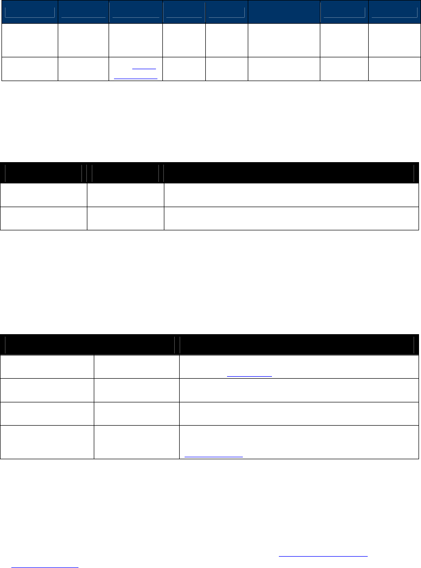
NEO Interface Developers Guide
208
Response Frame
Byte 0-9 Byte 10 Byte 11 Byte 12
Byte 13
Byte 14 …
Byte 14+n-1
Byte 14+n
Byte 15+n
Header Tag
& Protocol
Version
Command
Status Code
Data
Length
(MSB)
Data
Length
(LSB)
Data CRC (MSB)
CRC (LSB)
ViVOtech2\0
03h
See Status
Code Table
See Data Tables
If the Status Code is OK then the format and contents of the data field in the Response Frame
are given in the following table. All TLV lengths include the Tag and Length bytes.
Table 49: Update Balance Format and Contents When Status OK
Data Item Length (Bytes) Description
TLV Track 2
Equivalent Data
21
Track 2 Equivalent Data as a TLV object.
Tag: 57 Format: b19
TLV Auth_Code
9
Authorization Code as a TLV object
Tag: E300 Format: b8
If the Status Code being returned in the Response Frame is “Failed”, then the contents of the
Data field contains further information on the cause of the failure and does not contain the
Authorization Code etc. In this case the Data field in the Response Frame has the following
format.
Table 50: Update Balance Format and Contents When Status Not OK
Data Field Length (bytes) Description
Error Code
1
Error Code giving the reason for the failure. See sub-
section on Error Codes
SW1
1
Value of SW1 returned by the Card (SW1SW2 is 0000 if SW1
SW2 not available)
SW2
1
Value of SW2 returned by the Card (SW1SW2 is 0000 if SW1
SW2 not available)
RF State Code
1
RF State Code indicating exactly where the error occurred
in the Reader-Card transaction flow. See sub-section on
RF State Codes.
For any other Status Code the data field is empty.
Cancel Transaction Command (05-01)
Use this command to stop reader/card communication after the Activate Transaction command
or Update Balance command has been sent to the reader.
After the terminal has issued the Cancel Transaction command, the terminal should not send
any commands until it receives a response from the reader. If the reader receives the Cancel
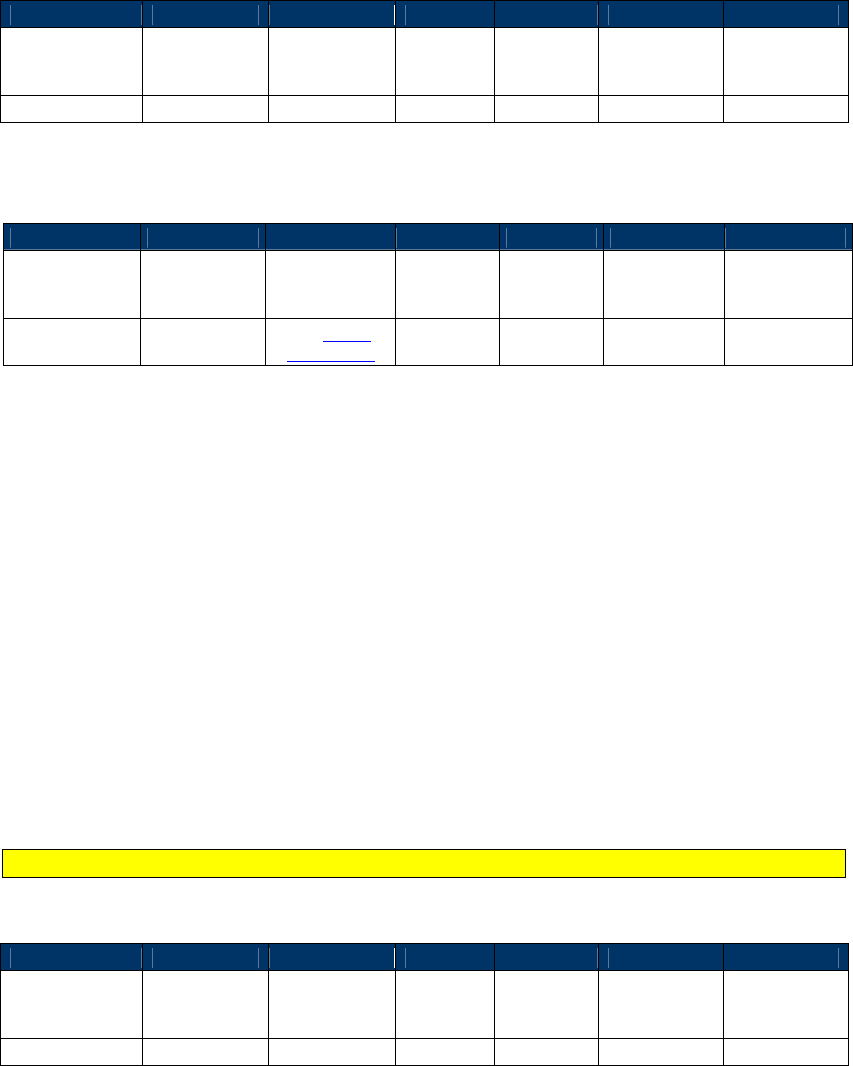
NEO Interface Developers Guide
209
Transaction command before it sends the response to an Activate command, it only sends the
Cancel Transaction response. The reader then enters an “idle” state and waits for the next
command from the terminal.
Command Frame
Byte 0-9
Byte 10
Byte 11
Byte 12
Byte 13
Byte 14
Byte 15
Header Tag &
Protocol
Version
Command Sub-
Command
Data
Length
(MSB)
Data
Length
(LSB)
CRC (LSB) CRC (MSB)
ViVOtech2\0
05h
01h
00h
00h
Response Frame
Byte 0-9
Byte 10
Byte 11
Byte 12
Byte 13
Byte 14
Byte 15
Header Tag &
Protocol
Version
Command Status Code
Data
Length
(MSB)
Data
Length
(LSB)
CRC (MSB) CRC (LSB)
ViVOtech2\0 05h
See Status
Code Table
00h 00h
MasterCard M/Chip 3.0 Transaction Commands
This section describes commands that are specific to MasterCard M/Chip 3.0
transaction behavior.
Stop Transaction (05-02)
The Stop Transaction command is similar to the Cancel command. However,
the transaction will exit at whatever phase it was currently in. Depending on
timing, the transaction could exit with an Activate Response. In that case, the
Stop command was received too late to stop the transaction. Receipt of any
response other than the Stop response is proof that the Stop command did not
execute.
The Stop command is currently only used by the MasterCard M/Chip 3.0 application.
Command Frame
Byte 0-9
Byte 10
Byte 11
Byte 12
Byte 13
Byte 14
Byte 15
Header Tag &
Protocol
Version
Command Sub-
Command
Data
Length
(MSB)
Data
Length
(LSB)
CRC (LSB) CRC (MSB)
ViVOtech2\0
05h
02h
00h
00h
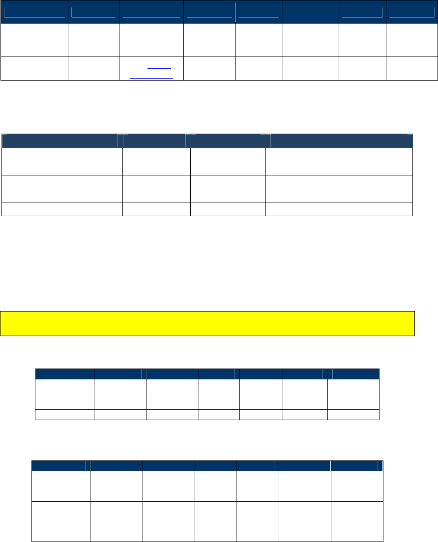
NEO Interface Developers Guide
210
Response Frame
Byte 0-9 Byte 10 Byte 11 Byte 12 Byte 13
Byte 14 …
Byte 14+n-1
Byte 14+n
Byte 15+n
Header Tag &
Protocol
Version
Command
Status Code
Data
Length
(MSB)
Data
Length
(LSB)
Data
CRC (MSB)
CRC (LSB)
ViVOtech2\0 05h
See Status
Code Table
00h 30h See below
The following information is returned in the data field of a successful Stop
command:
Data item
Tag
Tag Len
Notes
Outcome Parameter
Set TLV
DF8129h
12
Discretionary Data
TLV
FF8106h
10
Encapsulates the Error
TLV
Error Indication TLV
DF8115
6
Reset Torn Transaction Log (84-0E)
The Reset Torn Transaction Log effectively erases the content of the torn
transaction log and sets it back to an “empty” state.
Normally, this function will only be used in certification scenarios where the torn transaction
log must be put into a known state before performing a test.
Command Frame
Byte 0-9
Byte 10
Byte 11
Byte 12
Byte 13
Byte 14
Byte 15
Header Tag
& Protocol
Version
Command
Sub-
Command
Data
Length
(MSB)
Data
Length
(LSB)
CRC
(LSB)
CRC
(MSB)
ViVOtech2\0
84h
0Eh
00h
00h
Varies
Varies
Response Frame
Byte 0-9
Byte 10
Byte 11
Byte 12
Byte 13
Byte 14
Byte 15
Header Tag
& Protocol
Version
Command
Status
Data
Length
(MSB)
Data
Length
(LSB)
CRC
(LSB)
CRC
(MSB)
ViVOtech2\0
84h
Refer to
standard
status
values
00h 00h Varies Varies
This command, when sent, will restore the Torn Transaction Log back to its
original pristine state, as if a power up had just occurred.

NEO Interface Developers Guide
211
Clean Torn Transaction Log (84-0F) Command
This command is used to remove Torn Transaction Log entries that have
exceeded the allowed lifetime defined in tag DF811C (Maximum Lifetime of
Torn Transaction Log Record).
Command Frame
Byte 0-9
Byte 10
Byte 11
Byte 12
Byte 13
Byte 14
Byte 15
Header Tag
& Protocol
Version
Command
Sub-
Command
Data
Length
(MSB)
Data
Length
(LSB)
CRC
(LSB)
CRC
(MSB)
ViVOtech2\0
84h
0Fh
00h
00h
Varies
Varies
Response Frame
Byte 0-9 Byte 10 Byte 11
Byte
12
Byte
13
Byte
14-N
Byte
N + 1
Byte
N + 2
Header Tag
& Protocol
Version
Command
Status
Data
Length
(MSB)
Data
Length
(LSB)
Data
CRC
(LSB)
CRC
(MSB)
ViVOtech2\0
84h
Refer to
standard
status
values
XX XX
List of
Torn
TLV’s
Varies
Varies
The response may contain expiring torn entries. These are returned inside a
Discretionary Data tag, as shown below:
Byte 0-2
Byte 3
Bytes 4-6
Byte 7
Byte 8-N
Discretionary
Data
Tag
Length
Torn
Transaction
Tag
Length
TLV’s for Torn
Record
FF8106h
Varies
FF8101h
Varies
Varies
NOTE: The terminal should execute the CLEAN command repeatedly, until no
more torn records are sent back to it. In other words, in the final response, the
value length of tag FF8106 shall be 0.
Refer to the M/Chip PayPass specification for the contents of the Torn
Transaction Log Record.
9.1.1.1 Torn Transaction Log Timer
The reader keeps track of how much time has elapsed for each torn transaction
record. However, it does not take any action when this time has expired. Since
the interface between the terminal/POS and the Reader is a command/response
interface, cleaning the torn transaction log must be initiated by the
terminal/POS.

NEO Interface Developers Guide
212
Periodically, the POS should initiate a cleaning cycle and repeatedly issue the
“Clean” command (84-0F) at that point until the reader reports that the Torn
Log has been successfully purged.
How the POS accomplishes this is beyond the scope of the interface and this
document.
Visa VCPS Transaction Commands
Set Cash Transaction Reader Risk Parameters (04-0C)
This command creates or modifies the TTQ and reader risk parameters associated with VCPS
2.1.1 cash transactions. Visa defines a “cash” transaction as a transaction that results in cash
only being returned, like a bank machine withdrawal. If the transaction is a cash transaction and
the Cash Transaction RR enable is set in the default FFF4 Visa Reader Risk Flags tag, then the
reader risk parameters provided are used instead of the default TTQ and reader risk parameters.
Once the transaction has been completed the TTQ and reader risk parameters are returned to
their default settings.
Command Frame
Byte 0-9 Byte 10 Byte 11 Byte 12
Byte 13
Byte 14 …
Byte 14+n-1 Byte 14
Byte 15
Header Tag &
Protocol
Version
Command Sub-
Command
Data
Length
(MSB)
Data
Length
(LSB)
Data CRC
(LSB)
CRC
(MSB)
ViVOtech2\0 04h 0Ch 00h 00h
TLV Data
Objects (see
Cash
Transaction
TLVs)
Important: All the TLVs listed in the table below are mandatory. If any are omitted, the
command returns an error.
Table 51: Cash Transaction TLVs
Tag Data Object Name and Description Format Length
(Bytes)
9F1B
Terminal Floor Limit
Indicates the floor limit in the terminal in for a Visa Cash or
Cashback Transaction (hex).
b 4
9F66
Visa Terminal Transaction Qualifier (TTQ)
Determines the characteristics of the transaction for a Cash
transaction.
b 4
FFF1[1]
Terminal Contactless Transaction Limit
Indicates the floor limit in the terminal for a Visa Cash
transaction.
n12 6
NEO Interface Developers Guide
213
Tag Data Object Name and Description Format Length
(Bytes)
FFF4[1]
Visa Reader Risk Flags
Byte 1
b8
b7
b6
b5
b4
b3
b2
b1
Meaning (0 = disable, 1 = enable)
-
-
-
-
-
-
-
X
Status Check
X
X
X
X
X
X
X
-
RFU
Byte 2:
b8
b7
b6
b5
b4
b3
b2
b1
Meaning (0 = disable, 1 = enable)
-
-
-
-
-
-
-
X
Transaction Limit Check
-
-
-
-
-
-
X
-
CVM Required Limit Test
-
-
-
-
-
X
-
-
Terminal Floor Limit Check
-
-
-
-
X
-
-
-
Cash Transaction Reader Risk (RR)
-
-
-
X
-
-
-
-
Cashback Reader Risk (RR)
-
-
X
-
-
-
-
-
DRL (Dynamic Reader Limits) RR
X
X
-
-
-
-
-
-
RFU
Byte 3
b8
b7
b6
b5
b4
b3
b2
b1
Meaning
-
-
-
-
-
-
-
X
Zero Amount Test
0 = If amount is zero, transaction
disallowed
1 = If amount is zero, online cryptogram
required in the TTQ (9F66)
X
Zero Amount Test. If 0, bit 1 is ignored.
X
X
X
X
X
X
-
RFU
b 3
FFF5[1]
CVM Required Limit
Indicates the CVM required floor limit for a Visa Cash transaction.
n12 6
Response Frame
Byte 0-9
Byte 10
Byte 11
Byte 12
Byte 13
Byte 14+n
Byte 15+n
Header Tag &
Protocol
Version
Command Status Code
Data
Length
(MSB)
Data
Length
(LSB)
CRC (MSB) CRC (LSB)
ViVOtech2\0 04h
See Status
Code Table
Get Cash Transaction Reader Risk Parameters (03-0C)
This command returns the TTQ and reader risk parameters that will be used for cash
transactions, if enabled.
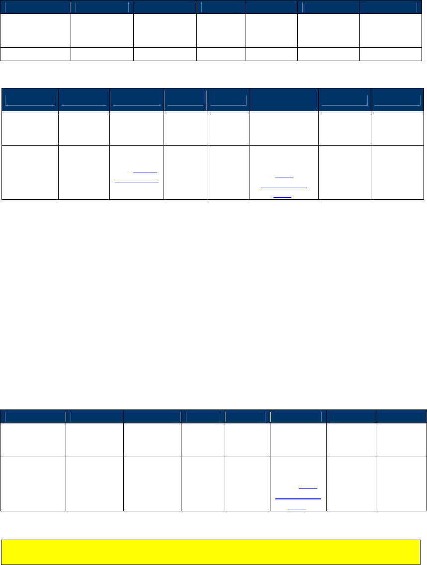
NEO Interface Developers Guide
214
Command Frame
Byte 0-9
Byte 10
Byte 11
Byte 12
Byte 13
Byte 14
Byte 15
Header Tag &
Protocol
Version
Command Sub-
Command
Data
Length
(MSB)
Data
Length
(LSB)
CRC (LSB) CRC (MSB)
ViVOtech2\0
03h
0Ch
00h
00h
Response Frame
Byte 0-9 Byte 10 Byte 11 Byte 12
Byte 13
Byte 14 …
Byte 14+n-1
Byte 14+n
Byte 15+n
Header Tag
& Protocol
Version
Command
Status Code
Data
Length
(MSB)
Data
Length
(LSB)
Data CRC (MSB)
CRC
(LSB)
ViVOtech2\0
03h See Status
Code Table
TLV Data
Objects (see
Cash
Transaction
TLVs)
The only Data Objects that should be returned are the Cash Transaction TLVs sent in the Set
Cash Transactions Reader Risk Parameters command (9F66, FFF1, FFF5, and 9F1B).
Set Cashback Transaction Reader Risk Parameters (04-0D)
This command creates or modifies the TTQ and reader risk parameters associated with a VCPS
2.1.1 cashback transaction. Visa defines a “cashback” transaction as a transaction that results in
the purchase of merchandise with cash being returned. If the transaction is a cashback
transaction and the Cashback Transaction Reader Risk enable is set in the default FFF4 Visa
Reader Risk Flags tag, then the reader risk parameters provided are used instead of the default
TTQ and reader risk parameters. Once the transaction has been completed the TTQ and reader
risk parameters are returned to their default settings.
Command Frame
Byte 0-9
Byte 10
Byte 11
Byte 12
Byte 13
Data
Byte 14
Byte 15
Header Tag &
Protocol
Version
Command Sub-
Command
Data
Length
(MSB)
Data
Length
(LSB)
Data CRC (LSB)
CRC (MSB)
ViVOtech2\0
04h 0Dh 00h 00h
TLV Data
Objects
(see Cash
Transaction
TLVs)
Important: All the TLVs listed in the Cash Transactions TLVs table are mandatory. If any are
omitted, the command returns an error.
On ViVOpay Readers there are three ways to initiate a Cashback Transaction:
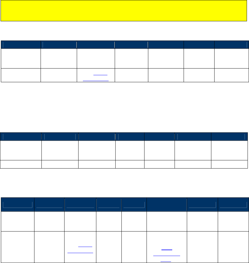
NEO Interface Developers Guide
215
1. If you define an Authorized Amount (9F02) that is greater than the Other Amount (9F03),
and the Other Amount is greater than zero, then the transaction will be treated as a
Cashback transaction. These parameters may be configured through configuration
commands or by including them in the Activate (02-01) command.
2. If you configure the Transaction Type (9C) using serial commands, or if you provide the
Transaction Type (9C) in the Activate Transaction command and set its value to 0x09, then
the transaction will be treated as a Cashback transaction.
3. If you provide an Other Amount (9F03) with a valid length of 6 bytes in the Activate
Transaction Command, the transaction will be treated as a Cashback transaction.
While the concept of cashback transactions may be applied to other card applications, the
command to set Reader Risk Parameters (04-0D) only applies to Visa. It allows the creation
or modification of the TTQ (Terminal Transaction Qualifiers).
Response Frame
Byte 0-9
Byte 10
Byte 11
Byte 12
Byte 13
Byte 14+n
Byte 15+n
Header Tag &
Protocol
Version
Command Status Code Data Length
(MSB)
Data Length
(LSB) CRC (MSB)
CRC
(LSB)
ViVOtech2\0 04h
See Status
Code Table 00 00
Get Cashback Transaction Reader Risk Parameters (03-0D)
This command returns the TTQ and reader risk parameters for all cashback transactions.
Command Frame
Byte 0-9
Byte 10
Byte 11
Byte 12
Byte 13
Byte 14
Byte 15
Header Tag &
Protocol
Version
Command Sub-
Command
Data
Length
(MSB)
Data
Length
(LSB)
CRC (LSB) CRC (MSB)
ViVOtech2\0
03h
0Dh
00h
00h
Response Frame
Byte 0-9 Byte 10 Byte 11 Byte 12
Byte 13
Byte 14 …
Byte 14+n-1
Byte 14+n
Byte 15+n
Header Tag
& Protocol
Version
Command
Status Code
Data
Length
(MSB)
Data
Length
(LSB)
Data CRC (MSB)
CRC
(LSB)
ViVOtech2\0
03h See Status
Code Table
TLV Data
Objects (see
Cash
Transaction
TLVs)

NEO Interface Developers Guide
216
The only Data Objects that should be returned are the Cash Transaction TLVs sent in the Set
Cash Transactions Reader Risk Parameters command (9F66, FFF1, FFF5, and 9F1B).
Set DRL Reader Risk Parameters (04-0E)
This command creates or modifies the Application Program ID and reader risk parameters for
four Dynamic Reader Limit sets. If a Visa card provides an Application Program ID that matches
one of the four programmed in the reader DRL sets and the DRL RR enable is set in the default
FFF4 Visa Reader Risk Flags tag, the Reader risk parameters for that DRL are used during the
transaction. Once the transaction has been completed the Reader risk parameters are returned
to their default settings.
Command Frame
Byte 0-9 Byte 10 Byte 11 Byte 12
Byte 13
Byte 14 …
Byte 14+n-1
Byte 14+n
Byte
15+n
Header Tag &
Protocol
Version
Command
Sub-
Command
Data
Length
(MSB)
Data
Length
(LSB)
Data
CRC (LSB)
CRC
(MSB)
ViVOtech2\0 04h 0Eh 00h 01h
DRL Index
and TLVs
Important: All the TLVs listed in the table below are mandatory. If any are omitted, the
command returns an error.
Table 52: DRL TLVs
Tag Data Object Name and Description Format Length
(Bytes)
None
DRL Index
This index refers to which DRL set (1 – 4) this data belongs. b 1
9F1B
Terminal Floor Limit
Changes the Floor Limit for the DRL (hex).
b 4
9F5A
Application Program ID
Determine the characteristics of the transaction for the DRL.
b 16
FFF1[1]
Terminal Contactless Transaction Limit
Indicates the floor limit in the terminal for the DRL. n12 6
NEO Interface Developers Guide
217
Tag Data Object Name and Description Format Length
(Bytes)
FFF4[1]
Visa Reader Risk Flags
Byte 1
b8
b7
b6
b5
b4
b3
b2
b1
Meaning (0 = disable, 1 = enable)
-
-
-
-
-
-
-
X
Status Check
X
X
X
X
X
X
X
-
RFU
Byte 2:
b8
b7
b6
b5
b4
b3
b2
b1
Meaning (0 = disable, 1 = enable)
-
-
-
-
-
-
-
X
Transaction Limit Check
-
-
-
-
-
-
X
-
CVM Required Limit Test
-
-
-
-
-
X
-
-
Terminal Floor Limit Check
-
-
-
-
X
-
-
-
Cash Transaction Reader Risk (RR)
-
-
-
X
-
-
-
-
Cashback Reader Risk (RR)
-
-
X
-
-
-
-
-
DRL (Dynamic Reader Limits) RR
X
X
-
-
-
-
-
-
RFU
Byte 3
b8
b7
b6
b5
b4
b3
b2
b1
Meaning
-
-
-
-
-
-
-
X
Zero Amount Test
0 = If amount is zero, transaction
disallowed
1 = If amount is zero, online cryptogram
required in the TTQ (9F66)
X
Zero Amount Test. If 0, bit 1 is ignored.
X
X
X
X
X
X
-
RFU
b 3
FFF5[1]
CVM Required Limit
Indicates the CVM required floor limit for the DRL. n12 6
Response Frame
Byte 0-9
Byte 10
Byte 11
Byte 12
Byte 13
Byte 14+n
Byte 15+n
Header Tag &
Protocol
Version
Command Status Code
Data
Length
(MSB)
Data
Length
(LSB)
CRC (MSB) CRC (LSB)
ViVOtech2\0 04h
See Status
Code Table
Get DRL Reader Risk Parameters (03-0E)
This command returns the Index, Application Program ID, and reader risk parameters for the
DRL settings.
Command Frame
Byte 0-9 Byte 10 Byte 11 Byte 12
Byte 13
Byte 14 …
Byte 14+n-1
Byte 14+n
Byte
15+n
NEO Interface Developers Guide
218
Header Tag &
Protocol
Version
Command
Sub-
Command
Data
Length
(MSB)
Data
Length
(LSB)
Data
CRC (LSB)
CRC
(MSB)
ViVOtech2\0 03h 0Eh 00h 01h
DRL Index
(01-04)
Response Frame
Byte 0-9 Byte 10 Byte 11 Byte 12
Byte 13
Byte 14 …
Byte 14+n-1
Byte 14+n
Byte 15+n
Header Tag
& Protocol
Version
Command
Status Code
Data
Length
(MSB)
Data
Length
(LSB)
Data CRC (MSB)
CRC
(LSB)
ViVOtech2\0
03h See Status
Code Table
TLV Data
Objects (see
DRL TLVs)
The response TLV Data Objects are formatted as shown in the table DRL Transaction TLVs (Index,
9F5A, FFF1, FFF4, FFF5, and 9F1B).
Key Management Commands
Warning: DO NOT mix Protocol 1 and Protocol 2 Key Management commands. The preferred
method is to use the Protocol 2 commands.
The Key Management Protocol 2 commands are the preferred method. The Key Management
Protocol 2 commands MUST be used when doing secure communication.
The following status codes may be generated in response to the CA Public Key commands.
The following status codes are specific to the Key Manager module. Their values may have
different meanings when used with other commands.
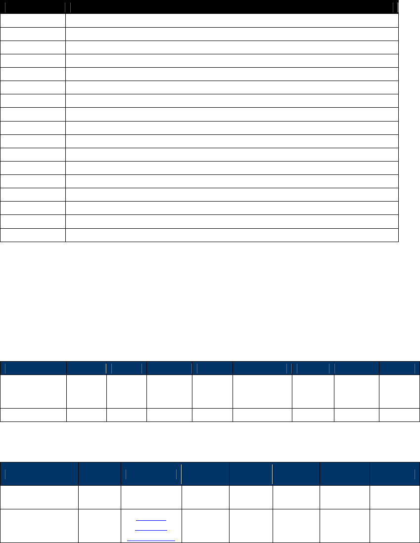
NEO Interface Developers Guide
219
Table 53: EMV Key Manager Status Codes – Protocol 2
Status Code
Status
00h
Operation was successful
20h
SAM Transceiver error – problem communicating with the SAM (see note below)
21h
Length error in data returned from the SAM
41h
Unknown Error from SAM
42h
Invalid data detected by SAM
43h
Incomplete data detected by SAM
44h
Reserved
45h
Invalid key hash algorithm
46h
Invalid key encryption algorithm
47h
Invalid modulus length
48h
Invalid exponent
49h
Key already exists
4Ah
No space for new RID
4Bh
Key not found
4Ch
Crypto not responding
4Dh
Crypto communication error
4Fh
All key slots are full (maximum number of keys has been installed)
Get CA Public Key (D0-01)
This command retrieves all of the information related to a specific key. It includes the key hash,
the algorithms, and so forth. See the data definition below:
Command Frame
Byte 0-9
Byte 10
Byte 11
Byte 12
Byte 13
Byte 14 – 18
Byte 19
Byte 20
Byte 21
Header Tag &
Protocol
Version
Cmd Sub
Cmd
Length
(MSB)
Length
(LSB) RID Key
Index
CRC
(LSB)
CRC
(MSB)
ViVOtech2\0
D0h
01h
00h
06h
varies
varies
Varies
Varies
Response Frame
Byte 0-9 Byte 10
Byte 11 Byte 12 Byte 13
Byte 19 –
n
Byte n+1
Byte n+2
Header Tag &
Protocol Version
Cmd Status
Length
(MSB)
Length
(LSB) Data
CRC
(LSB)
CRC
(MSB)
ViVOtech2\0 D0h
See Key
Manager
status codes
00h varies varies Varies Varies
When the status is successful (00h), the data field contains:
Key Hash Algorithm (1 Byte) - 01h = SHA-1

NEO Interface Developers Guide
220
Key Encryption Algorithm (1 Byte) – 01h = RSA
Checksum – This Checksum is calculated with a concatenation of:
RID & KeyIndex & Modulus & Exponent
where the exponent is either one byte or 3 bytes
Modulus Length (2 bytes)
Modulus (varies in length)
Get CA Public Key Hash (D0-02)
This command returns only the “Checksum” portion of the key.
Command Frame
Byte 0-9
Byte 10
Byte 11
Byte 12
Byte 13
Byte 14 – 18
Byte 19
Byte 20
Byte 21
Header Tag &
Protocol
Version
Cmd Sub
Cmd
Length
(MSB)
Length
(LSB) RID Key
Index
CRC
(LSB)
CRC
(MSB)
ViVOtech2\0
D0h
02h
00h
06h
varies
varies
Varies
Varies
Response Frame
Byte 0-9
Byte 10
Byte 11
Byte 12
Byte 13
Byte 19 – n
Byte n+1
Byte n+2
Header Tag &
Protocol Version
Cmd status
Length
(MSB)
Length
(LSB)
Data
CRC
(LSB)
CRC
(MSB)
ViVOtech2\0 D0h
See Key
Manager
status
codes
00h varies varies Varies Varies
Status = 00 if successful. When the status is successful, the data contains:
Key Hash Algorithm (1 byte)
Key Algorithm (1 byte)
Checksum (20 bytes) – calculated over the key information as previously described
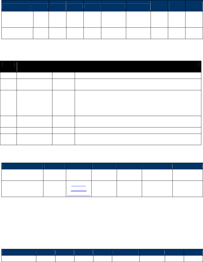
NEO Interface Developers Guide
221
Set CA Public Key (D0-03)
This command adds a new key in the reader.
Command Frame
Byte 0-9 Byte 10
Byte 11
Byte 12
Byte 13
Byte 14 – 18
Byte 19
Bytes
19-n
Byte
n+1
Byte
n+2
Header Tag &
Protocol
Version
Cmd
Sub
Cmd
Length
(MSB)
Length
(LSB)
RID
(5 bytes)
Key Index
(1 byte)
Key
Data
CRC
(LSB)
CRC
(MSB)
ViVOtech2\0 D0h 03h varies
varies
varies varies
See
below
Varies
Varies
Key Data is as follows: (all binary)
Byte
Name
Length
(bytes)
Description
0
Hash Algorithm
1
The only algorithm supported is SHA-1. The value is set to 01h
1
Public Key
Algorithm
1
The encryption algorithm in which this key is used. Currently
support only one type: RSA. The value is set to 01h
3-22
Checksum/Hash
20
Checksum which is calculated using SHA-1 over the following
fields:
RID & KeyIndex & Modulus & Exponent
where the exponent is either one byte or 3 bytes (although we
store it in a 4 byte field)
23-26
Public Key
Exponent
4
Actually, the real length of the exponent is either one byte or 3
bytes. It can have two values: 3, or 65537.
27-28
Modulus Length
2
Indicates the length of the next field.
29-n
Modulus
Variable
This is the modulus field of the public key. Its length is
specified in the field above.
Response Frame
Byte 0-9
Byte 10
Byte 11
Byte 12
Byte 13
Byte 14
Byte 15
Header Tag &
Protocol Version Cmd status
Length
(MSB)
Length
(LSB)
CRC
(LSB)
CRC
(MSB)
ViVOtech2\0 D0h
See Key
Manager
status codes
00h 00h Calculated Calculated
Delete CA Public Key (D0-04)
This command allows the POS to delete a specific key.
Command Frame
Byte 0-9
Byte 10
Byte 11
Byte 12
Byte 13
Byte 14 – 18
Byte 19
Byte 20
Byte 21
Header Tag &
Cmd
Sub
Length
Length
RID
Key Index
CRC
CRC
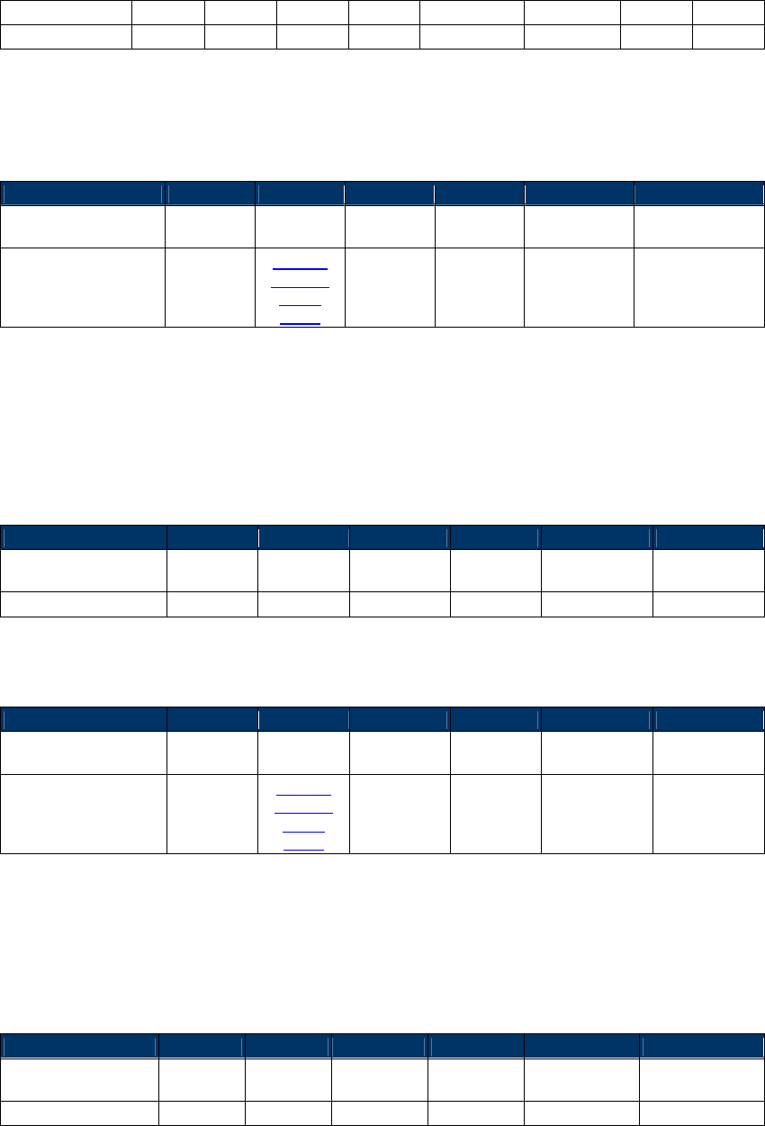
NEO Interface Developers Guide
222
Protocol Version
Cmd
(MSB)
(LSB)
(5 bytes)
(1 byte)
(LSB)
(MSB)
ViVOtech2\0
D0h
04h
00h
06h
varies
varies
Varies
Varies
The RID and Key Index for the key being deleted must be specified in the frame.
Response Frame
Byte 0-9
Byte 10
Byte 11
Byte 12
Byte 13
Byte 14
Byte 15
Header Tag &
Protocol Version Cmd status
Length
(MSB)
Length
(LSB)
CRC
(LSB)
CRC
(MSB)
ViVOtech2\0 D0h
See Key
Manager
status
codes
00h 00h Calculated Calculated
Delete All CA Public Keys (D0-05)
This command deletes all of the CA public keys.
Command Frame
Byte 0-9
Byte 10
Byte 11
Byte 12
Byte 13
Byte 14
Byte 15
Header Tag &
Protocol Version
Cmd
Sub
Cmd
Length
(MSB)
Length
(LSB)
CRC
(LSB)
CRC
(MSB)
ViVOtech2\0
D0h
05h
00h
00h
Calculated
Calculated
Response Frame
Byte 0-9
Byte 10
Byte 11
Byte 12
Byte 13
Byte 14
Byte 15
Header Tag &
Protocol Version
Cmd status
Length
(MSB)
Length
(LSB)
CRC
(LSB)
CRC
(MSB)
ViVOtech2\0 D0h
See Key
Manager
status
codes
00h 00h Calculated Calculated
Get All CA Public RIDs (D0-06)
The Get All CA Public RIDs command tells the reader to retrieve a list of all the RIDs.
Command Frame
Byte 0-9
Byte 10
Byte 11
Byte 12
Byte 13
Byte 14
Byte 15
Header Tag &
Protocol Version Cmd
Sub
Cmd
Length
(MSB)
Length
(LSB)
CRC
(LSB)
CRC
(MSB)
ViVOtech2\0
D0h
06h
00h
00h
Calculated
Calculated
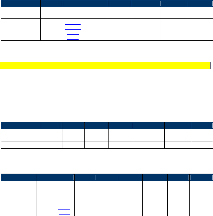
NEO Interface Developers Guide
223
Response Frame
Byte 0-9
Byte 10
Byte 11
Byte 12
Byte 13
Byte 13-n
Byte n+1
Byte n+2
Header Tag &
Protocol Version
Cmd status
Length
(MSB)
Length
(LSB) RID(s)
CRC
(LSB)
CRC
(MSB)
ViVOtech2\0 D0h
See Key
Manager
status
codes
00h varies Each RID is 5
bytes. Calculated
Calculated
Status 00h – RIDs returned with the number of RIDs = Length/5;
Note: If the length returned is 0, then the communication was good, but no RIDs are stored.
List CA Public Key IDs or RID (D0-07)
The following command retrieves a list of key indices that are installed for this RID.
Command Frame
Byte 0-9
Byte 10
Byte 11
Byte 12
Byte 13
Byte 14 – 18
Byte 19
Byte 20
Header Tag &
Protocol Version
Cmd
Sub
Cmd
Length
(MSB)
Length
(LSB)
RID
(5 bytes)
CRC
(LSB)
CRC
(MSB)
ViVOtech2\0
D0h
07h
00h
05h
varies
Varies
Varies
Response Frame
Byte 0-9
Byte 10
Byte 11
Byte 12
Byte 13
Byte 14-18
Byte 19 – n
Byte n+1
Byte n+2
Header Tag &
Protocol Version
Cmd status
Length
(MSB)
Length
(LSB)
RID
(5 bytes)
List of
Indices
CRC
(LSB)
CRC
(MSB)
ViVOtech2\0 D0h
See Key
Manager
status
codes
00h varies varies varies Varies Varies
Status – 00h = successful index retrieval
Module Versioning
The module versioning feature provides information about the firmware versions, and the
specification versions for specific modules, interfaces, and hardware in the reader. The information
is returned to the POS or the POS Simulator via the serial interface. Versioning of card
applications may also facilitate the tracking of changes for certification purposes.
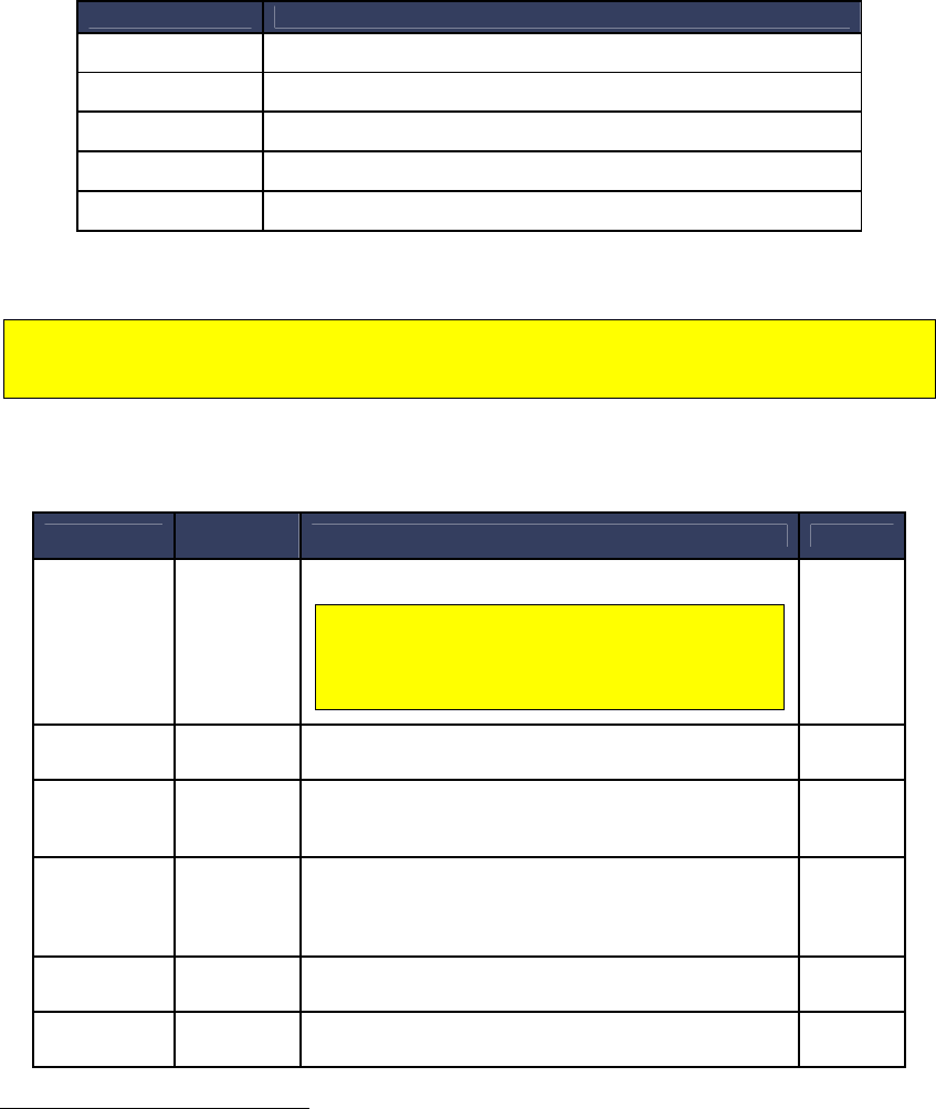
NEO Interface Developers Guide
224
The implementation of this feature has been simplified for the following reasons:
To align more closely with the behavior of the Advanced Reader firmware.
To make the version strings more accessible for human readers.
To facilitate maintenance of version strings.
The following subcommands are available for the Module Version command:
Sub-command Description
01h[1] Get Product Type
02h Get Processor Type
03h[1] Get Main Firmware Version
14h Get Hardware Information
20h Get Module Version Information3
[1]
Those sub-commands only work on Vendi.
Note: All other sub-commands for the Module version command have been deprecated.
However, a 0x00 in the sub-command field will return the same result as a 20h sub-command.
All other commands will return an “unknown sub-command” error.
The table below shows the information that is available and the subcommand that is used to
extract that information. The term “module” is used very loosely in the context of the firmware.
Module Type
Sub-
Command
Description Format
FW
20h The firmware version that is resident in the reader
For KioskIII, this verion number shows the
firmware version for Lab Verification, it
won’t change unless new Lab Verification is
done for the certain module.
ASCII
text
CL AppSel 20h Refers to the special application selection module and
version.
ASCII
text
CL AID
20h Contactless L2 Application specification/version (since
L2 applications are identified by the “application ID”,
this type refers to an AID)
ASCII
text
CL AppSpe
20h Contactless L2 Special Application
specification/version that not identified by the
“application ID” (Example: SmartTap and ApplePay
VAS)
ASCII
text
CL L1 20h L1 Interface specification/version ASCII
text
UI 20h User Interface specification/version ASCII
text
3
Previously a subcommand “0x00” was supported. It is being deprecated. However, because some of the ViVOpay
internal utilities used that command to determine if the reader was alive, a subcommand of 0x00 will behave exactly
the same as a subcommand 0x20 and will not give an error.

NEO Interface Developers Guide
225
Module Type
Sub-
Command
Description Format
SAM 14h Secure Access Module version string ASCII
text
HW 14h Hardware platform identifier ASCII
text
EEPROM 14h The EEPROM version ASCII
text
N/A 02h Returns the processor type in TLV format TLV
The module types described above appear in the response packet for the respective sub-
command. Refer to the examples in the response packet section.
Get Product Type (09-01)
This command returns a product type TLV.
Command Frame
Response Frame
The Get Product Type sub-command returns a TLV string as follows:
Tag: 0xDF60
Length: 0x03
Value: 3-byte field representing the product type.
The following example shows the command and response.
Command: Get Product Type
56 69 56 4F 74 65 63 68 32 00 09 01 00 00 A0 A0
Response:
56 69 56 4F 74 65 63 68 32 00 09 00 00 06 DF 60 03 43 36 00 DC 60
Byte 0-9 Byte 10 Byte 11 Byte 12 Byte 13 Byte 14 Byte 15
Header Tag
& Protocol Command
Sub-
Command
Data
Length
(MSB)
Data
Length
(LSB)
CRC
(LSB)
CRC
(MSB)
ViVOtech2\0
09h 01 00h 00h
Byte 0-9 Byte 10 Byte 11 Byte12 Byte 13 Byte 14 …
Byte 13+n
Byte
14+n
Byte
15+n
Header Tag
& Protocol Command
Status
Code
Data
Length
(MSB)
Data
Length
(LSB)
Data CRC
(MSB)
CRC
(LSB)
ViVOtech2\0
09h See Status
Code Table
See below

NEO Interface Developers Guide
226
Product Type
(hex values) Description
42 37 00 ViVOpay 5000
43 33 00 ViVOpay 4500
43 35 00 ViVOpay Vend
43 36 00 Vendi (NEO)
43 37 00 ViVOpay Kiosk1 (ATM1)
43 38 00 Kiosk2
43 39 00 Kiosk3 (NEO)
55 31 00 UniPay 1.5 (NEO)
55 33 00 UniPay III (NEO)
55 33 31 VP4880, VP4880 OEM (NEO) (iBase/Cake same code)
55 33 32 VP4880E(NEO)
55 33 33 VP4880C (NEO)
44 30 00 QX120
44 31 00 Mx8Series
44 32 00 NETs
44 33 00 Magtek
44 35 00 ICP
Get Processor Type (09-02)
This command returns a processor type TLV.
Command Frame
Response Frame
Byte 0-9 Byte 10 Byte 11 Byte 12 Byte 13 Byte 14 Byte 15
Header Tag
& Protocol Command
Sub-
Command
Data
Length
(MSB)
Data
Length
(LSB)
CRC
(LSB)
CRC
(MSB)
ViVOtech2\0
09h 02 00h 00h
Byte 0-9 Byte 10 Byte 11 Byte12 Byte 13 Byte 14 …
Byte 13+n
Byte
14+n
Byte
15+n
Header Tag
& Protocol Command
Status
Code
Data
Length
(MSB)
Data
Length
(LSB)
Data CRC
(MSB)
CRC
(LSB)
ViVOtech2\0
09h See Status
Code Table
See below
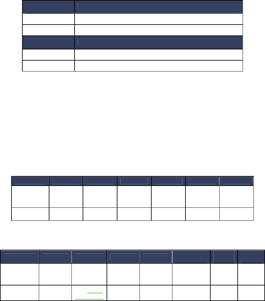
NEO Interface Developers Guide
227
The Get Processor Type sub-command returns a TLV string as follows:
Tag: 0xDF61
Length: 0x02
Value: a 1-byte field representing the processor type.
The following types of processors may be identified in the Value field:
Processor Type
(hex values) Description
45 00 ARM7/ LPC21xx
4D 00 ARM Cortex-M4/ K21 Family
Processor Type
(hex values) Description
45 00 ARM7/ LPC21xx
4D 00 ARM Cortex-M4/ K21 Family
The following example shows the command and response.
Command: Get Processor Type
56 69 56 4F 74 65 63 68 32 00 09 02 00 00 F0 F9
Response:
56 69 56 4F 74 65 63 68 32 00 09 00 00 05 DF 61 02 4D 00 AC 4D
Get Main Firmware Version (09-03)
This command returns main firmware version TLV.
Command Frame
Response Frame
The Get Main Firmware Version sub-command returns a TLV string as follows:
Byte 0-9 Byte 10 Byte 11 Byte 12 Byte 13 Byte 14 Byte 15
Header Tag
& Protocol Command
Sub-
Command
Data
Length
(MSB)
Data
Length
(LSB)
CRC
(LSB)
CRC
(MSB)
ViVOtech2\0
09h 03 00h 00h
Byte 0-9 Byte 10 Byte 11 Byte12 Byte 13 Byte 14 …
Byte 13+n
Byte
14+n
Byte
15+n
Header Tag
& Protocol Command
Status
Code
Data
Length
(MSB)
Data
Length
(LSB)
Data CRC
(MSB)
CRC
(LSB)
ViVOtech2\0
09h See Status
Code Table
See below

NEO Interface Developers Guide
228
Tag: 0xDF62
Length: Varies
Value: Varies field representing the main firmware version.
The following example shows the command and response.
Command: Get Main Firmware Version
56 69 56 4F 74 65 63 68 32 00 09 03 00 00 C0 CE
Response:
56 69 56 4F 74 65 63 68 32 00 09 00 00 14 DF 62 11 43 72 61 6E 65 56 65 6E
64 69 5F 31 2E 30 2E 30 00 E1 5D
Get Hardware Information (09-14)
Command Frame
Response Frame
The format for hardware module version information returned is “human readable”, consisting of
fields that are separated by commas, and lines separated by carriage return and line feed
characters:
<module type>,<module name><CRLF>
<chip version>
The following example shows the hardware version information subcommand and the information
being returned (in ASCII format).
Command: Get Hardware Version Information
56 69 56 4F 74 65 63 68 32 00 09 14 00 00 33 08
Response:
56 69 56 4F 74 65 63 68 32 00 09 00 00 15 48 57 2C 56 50 56 65 6E 64 69 0D 0A 4B 32 31 46 20
52 65 76 39
Byte 0-9 Byte 10 Byte 11 Byte 12 Byte 13 Byte 14 Byte 15
Header Tag
& Protocol Command
Sub-
Command
Data
Length
(MSB)
Data
Length
(LSB)
CRC
(LSB)
CRC
(MSB)
ViVOtech2\0
09h 14h 00h 00h
Byte 0-9 Byte 10 Byte 11 Byte12 Byte 13
Byte 14 …
Byte 13+n
Byte
14+n Byte 15+n
Header Tag
& Protocol Command
Status
Code
Data
Length
(MSB)
Data
Length
(LSB)
Data CRC
(MSB)
CRC
(LSB)
ViVOtech2\0
09h See Status
Code Table
See below
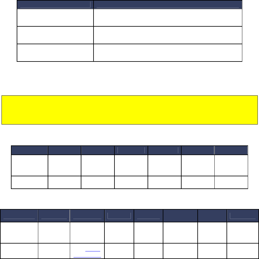
NEO Interface Developers Guide
229
ASCII translation of the data field:
HW,VPVendi<CR><LF>
K21F Rev9
ASCII Description
HW,VPVendi<CR><LF>
K21F Rev9 Vendi
HW,VPUnipayIII<CR><LF>
K21F Rev9 Unipay III
HW,VPUnipay1.5<CR><LF>
K21F Rev2 Unipay 1.5
Get Module Version Information (09-20)
For KioskIII, this verion number shows the modules version for Lab Verification, it won’t
change unless new Lab Verification is done for the certain module. So it may not be
consistent with the result of “Get ViVOpay Firmware Version (29-00)” and “Get Main
Firmware Version (09-03)”
Command Frame
Response Frame
If there is an error, the appropriate Status Code will be returned with an empty Data field (Data
Length = 0000h).
The format for module version information returned is “human readable”, consisting of fields that
are separated by commas, and lines separated by carriage return and line feed characters:
<module type>,<module name and spec. version>,[<implementation version>],<CRLF>
Byte 0-9 Byte 10 Byte 11 Byte 12 Byte 13 Byte 14 Byte 15
Header Tag
& Protocol Command
Sub-
Command
Data
Length
(MSB)
Data
Length
(LSB)
CRC
(LSB)
CRC
(MSB)
ViVOtech2\0
09h 20h 00h 00h
Byte 0-9 Byte 10 Byte 11 Byte12 Byte 13
Byte 14 …
Byte 13+n
Byte
14+n
Byte 15+n
Header Tag
& Protocol Command
Status
Code
Data
Length
(MSB)
Data
Length
(LSB)
Data CRC
(MSB)
CRC
(LSB)
ViVOtech2\0
09h See Status
Code Table
See below

NEO Interface Developers Guide
230
The following example shows the module version information subcommand and the information
being returned (in ASCII format).
Command: Get Module Version Information
56 69 56 4F 74 65 63 68 32 00 09 20 00 00 56 11
Response:
56 69 56 4F 74 65 63 68 32 00 09 00 01 2A 46 57 2C 56 65 6E 64 69 20 56 31 2E 30 30 2C 2C
0D 0A 20 46 53 26 44 42 20 56 31 2E 30 30 2C 2C 0D 0A 20 43 4C 20 41 70 70 53 65 6C 2C 50
50 53 45 20 4D 6F 64 75 6C 65 2C 20 76 31 2E 30 30 2C 2C 0D 0A 20 43 4C 20 41 49 44 2C 4D
61 73 74 65 72 43 61 72 64 20 50 61 79 50 61 73 73 20 4D 2F 43 68 69 70 20 76 33 2E 30 2E 32
2C 20 56 65 6E 64 69 20 76 31 2E 30 2E 30 2C 2C 0D 0A 20 43 4C 20 41 49 44 2C 56 69 73 61
20 56 43 50 53 20 32 2E 31 2E 33 2C 20 76 30 2E 39 39 2C 2C 0D 0A 20 43 4C 20 41 49 44 2C
41 6D 65 78 20 45 78 70 72 65 73 73 50 61 79 20 33 2E 30 2C 20 76 31 2E 30 30 2C 2C 0D 0A
20 43 4C 20 41 49 44 2C 44 69 73 63 6F 76 65 72 20 44 50 41 53 20 31 2E 30 20 5A 69 70 20 33
2E 31 2E 32 2C 20 76 31 2E 30 30 2C 2C 0D 0A 20 43 4C 20 41 49 44 2C 49 6E 74 65 72 61 63
20 31 2E 35 2C 20 76 31 2E 30 30 2C 2C 0D 0A 20 43 4C 20 4C 31 2C 45 4D 56 20 34 2E 33 20
4C 31 2C 20 76 31 2E 30 30 00 8C 33
ASCII translation of the data field:
FW,Vendi V1.00,,<CR><LF>
FS&DB V1.00,,<CR><LF>
CL AppSel,PPSE Module, v1.00,,<CR><LF>
CL AID,MasterCard PayPass M/Chip v3.0.2, Vendi v1.0.0,,<CR><LF>
CL AID,Visa VCPS 2.1.3, v0.99,,<CR><LF>
CL AID,Amex ExpressPay 3.0, v1.00,,<CR><LF>
CL AID,Discover DPAS 1.0 Zip 3.1.2, v1.00,,<CR><LF>
CL AID,Interac 1.5, v1.00,,<CR><LF>
CL L1,EMV 4.3 L1, v1.00<NUL>
International Language Support
The goal of this feature is to offer support for foreign languages including those based on
graphical fonts (i.e. Chinese, Thai, Arabic…).
Four core language options built into it. Some of these are font-based; the others are ideogram-
based. The ideogram language options are stored in flash as bitmaps. The other languages use
fonts that have been stored in flash.
For example, an English message is composed of multiple small bitmaps that represent different
characters (i.e., a “Thank You” message is 8 bitmaps displayed together). The ideogram
messages are (usually) a single bitmap (i.e., the Chinese “Thank You” message is a single bitmap
displayed on the screen). See Appendix A.7 Preparing Bitmaps for Use by ILM for instruction on
working with bitmaps.
Each reader keeps four “core” languages in its firmware. This ensures that the reader can be
used in virtually any geographical area “as is”. A core language may NOT be modified or deleted
by customer/third party actions. They always exist and are always available for use.
At present, there are four (4) Core Languages available:
English (U.S., fonts)

NEO Interface Developers Guide
231
French (fonts)
Chinese (ideograms)
English + Chinese (fonts & ideograms)
See Set Configuration (04-00) for information on how to set a language preference.
Other Language
In addition to the Core Languages, a fifth language called “Other Language” is available. This is
a ‘slot’ in flash memory that can contain all the message bitmaps for a language.
Since this Other Language is stored in the ideogram bitmap format, it eliminates the need for
fonts, etc., for this language. The Other Language only needs a unique record for each distinct
message it must display.
At present there are twenty-two (22) predefined message types that can be displayed.
Note: Each time you configure the reader for ILM, you must download messages for all 22
indices in consecutive order. You cannot change individual messages.
Bitmap Conversion Completed by POS
The reader expects to load a simplified version of the monochrome bitmap. While data is the
same as in a standard bitmap, it must be converted to a format that the LCD hardware can use.
The standard 40-byte DIB bitmap header is discarded. It is replaced by a simplified ViVOpay
header, described in ILM Header Format.
The bitmap data produces an LCD image that is:
Reversed in color (black is white, and vice versa).
Upside down.
White space reduction
Large parts of the bitmap are empty background. The LCD does not need to save this white
space, since it corresponds to off-pixel values (which are already turned off). This limited form
of image compression makes the image much smaller.
ILM Header Format
Each bitmap loaded onto a reader is expected to contain a proprietary header instead of the
standard DIB header.
This header format is shown in the following table, prefixed to the actual bitmap data:
Bytes
0-1
Bytes
2-3
Bytes
4-5
Bytes
6-7
Bytes
8-9
Bytes
10-11
Bytes
12…n
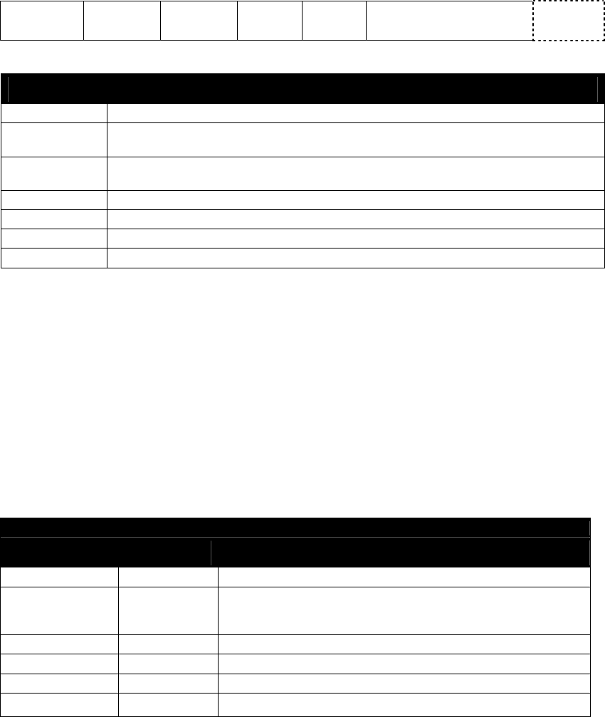
NEO Interface Developers Guide
232
Bitmap
Length
Row
Number
Column
Number Height Width Type (truncate, etc.) Bitmap
data
All variables in the header are 2 bytes long.
Byte Description
Bitmap Length
This data field contains the total number of bytes in the Bitmap Data Field.
Row Number
This data field contains the row offset that this image should start at. Value is in
PIXELS.
Column Number
This data field contains the column offset that this image should start at. Value is in
BYTES.
Height
This data field contains the number of rows (in pixels) that this image contains.
Width
This data field contains the number of columns (in bytes) that this image contains.
Type
Reserved – must be set to 00h.
Bitmap Data
This is the actual image data.
Language Version Information
This block contains data used for version control of the ILM. It contains variables that identify
the particular language module that is currently stored in the system.
The language module specifies both the language name and the Country Code. This is done
because there are a number of languages (English, French, Spanish, etc.) that are shared by
multiple nations but the reader is intended to be operate in a particular country (such as
Canada).
Table 54: Language Version Information
Language Version Information
Variable Length (bytes)
Description/Example
Language Name
25
ASCII String, Null Terminated – “Spanish\0”
Abbreviation 4
ASCII String, Null Terminated – “ES\0” ( ASCII-2 character
Country Code) or “ESP\0” (ASCII-3 character Country Code) or
“724\0” (3 digit decimal number Country Code)
Format
1
Unsigned 8-bit Integer
Author
10
ASCII String, Null Terminated – “NCR\0”
Version
6
ASCII String, Null Terminated – “1.3\0”
ID 4 Unsigned 32-bit Integer
Language Name is the name of the ILM language, using ASCII characters.
Abbreviation is the Country Code listed in ISO 3166. The format is either ASCII-2 character,
ASCII-3 character or a 3 digit decimal number. Regardless of method, it is stored in ASCII
alphanumeric characters.
The Format data field specifies the format of the Abbreviation field noted above. All follow the
specification from ISO DOC 3166.

NEO Interface Developers Guide
233
Format Data Field
Value Description/Example
01
02
03
Alpha2 (2 character) – “ES\0”
Alpha3 (3 character) – “ESP\0”
Decimal (3 digit) – “724\0”
Author is an ASCII string noting the customer that developed this language module.
Version is an ASCII string, also customer defined. It identifies this language module by version
number.
ID is a value that is reserved for future use. It is currently NOT used.
All fields are the length indicated. If (as is usually the case) the ASCII string does not occupy the
entire data field, the remaining bytes MUST be padded with zeroes.
The Language Version Information area is provided to the customer as a way to track which
language is currently loaded into the reader. It can be accessed and values are returned to the
POS. The intent is to facilitate automated updating through the POS. The POS can examine the
existing language module currently stored, and then make appropriate decisions as to its use
(i.e., updating the module).
How the Language Version Information is used by the customer cannot be defined or enforced. It
is only provided for identification and could be unused.
However, value of 00h in this area is interpreted as indicating that the ILM area of flash memory
is empty. Therefore, if the customer does edit the ILM area, they MUST update this Version
Information area as well, if only to write arbitrary non-zero values to it.
EMV Certificate Revocation List Commands
The Certificate Revocation List (CRL) contains entries that include the RID, Key
Index and Certificate Serial Numbers for cards that should be rejected. The
kernel checks the CRL for entries matching the index and serial number of the
Issuer Public Key Certificate provided by the card. If it is found the card is
rejected.
The CRL is maintained in non-volatile memory but a copy is kept in RAM to
provide faster access during transactions. A tag (DF26h) is defined to enable or
disable the entire Revocation feature in the reader.
The M/Chip 3.0 application is the only application capable of using the Certificate
Revocation List feature.
The firmware supports a maximum of 30 entries in the certificate revocation list.
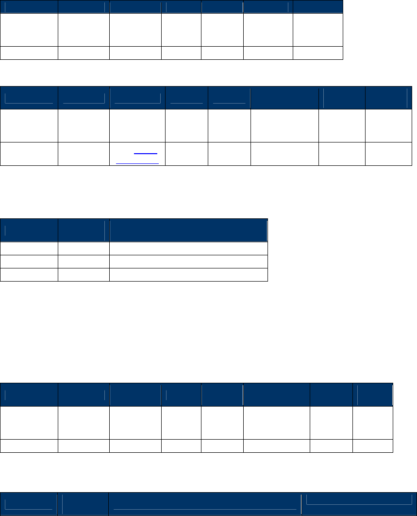
NEO Interface Developers Guide
234
Get EMV Revocation Log Status (84-03)
This command returns information about the EMV revocation log. The
information returned can be used by the terminal/POS to determine how to
read the log.
Command Frame
Byte 0-9
Byte 10
Byte 11
Byte 12
Byte 13
Byte 14
Byte 15
Header Tag
& Protocol
Version
Command
Sub-
Command
Data
Length
(MSB)
Data
Length
(LSB)
CRC
(LSB)
CRC
(MSB)
ViVOtech2\0
84h
03h
00
00
Response Frame
Byte 0-9 Byte 10 Byte 11 Byte 12
Byte 13
Byte 14 …
Byte 13+n
Byte
14+n
Byte
15+n
Header Tag
& Protocol
Version
Command
Status
Data
Length
(MSB)
Data
Length
(LSB)
Data CRC
(LSB)
CRC
(MSB)
ViVOtech2\0
84h
See Status
Code Table
TLV Data
Objects
If the command is successful, the following data is returned. All fields are
encoded with MSB first.
Offset
Length
(bytes) Data Description
00h
4
Version number
04h
4
Number of records
08h
4
Size of records
Add Entry to EMV Revocation List (84-04)
This command adds a new entry to the revocation list. The new entry is added
at the end of the revocation list.
Command Frame
Byte 0-9 Byte 10 Byte 11 Byte 12
Byte 13
Byte 14 …
Byte13+n
Byte
14+n
Byte
15+n
Header Tag
& Protocol
Version
Command
Sub-
Command
Data
Length
(MSB)
Data
Length
(LSB)
Data CRC
(LSB)
CRC
(MSB)
ViVOtech2\0
84h
04h
00
09
The data field contains the revocation list entry:
Offset
Length
(bytes) Data Description
Example
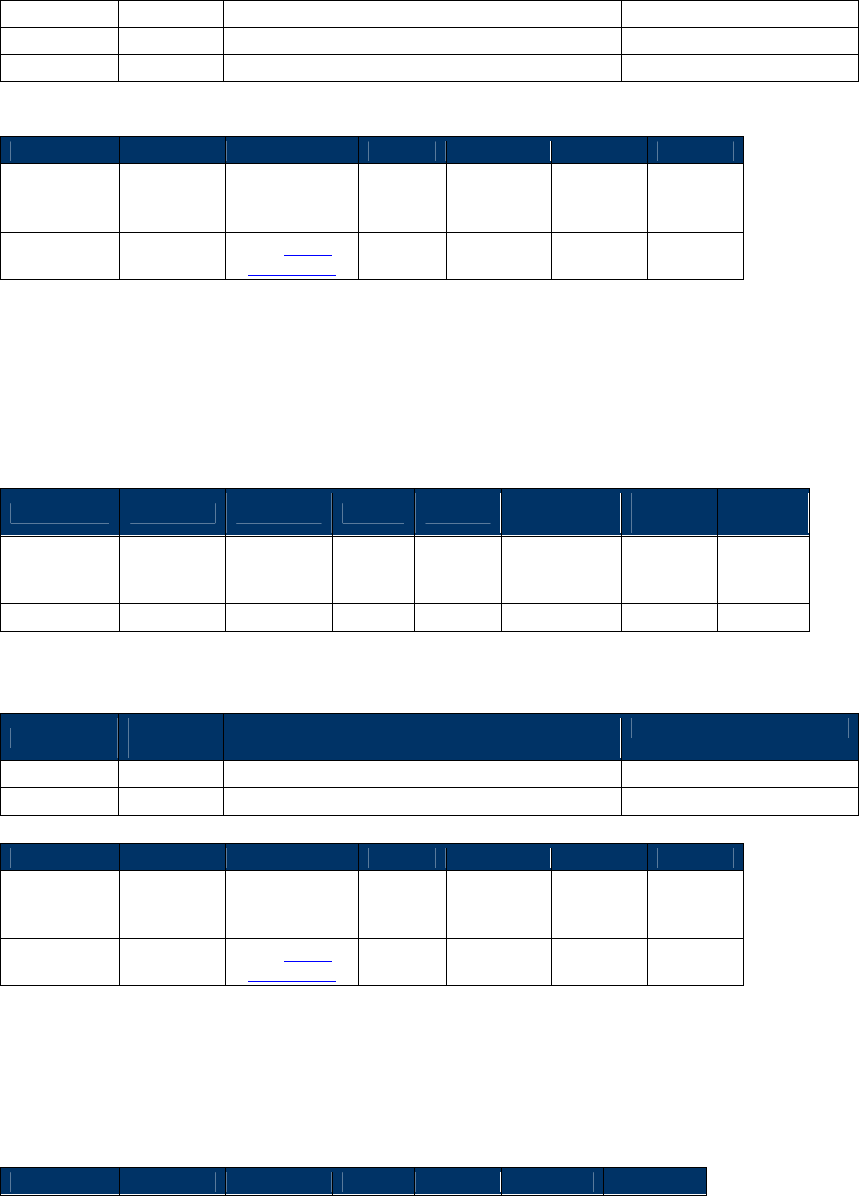
NEO Interface Developers Guide
235
00h
5
RID (packed hex format)
A0 00 00 00 04
04h
1
Key Index (packed hex format)
F8
08h
3
Certificate serial number (packed hex format)
00 10 00
Response Frame
Byte 0-9
Byte 10
Byte 11
Byte 12
Byte 13
Byte 14
Byte 15
Header Tag
& Protocol
Version
Command
Status
Data
Length
(MSB)
Data
Length
(LSB)
CRC
(LSB)
CRC
(MSB)
ViVOtech2\0
84h
See Status
Code Table
00 00
Delete All Entries for Single Index in EMV Revocation List (84-05)
This command deletes all entries that match a key index and RID from the EMV
revocation list.
Command Frame
Byte 0-9 Byte 10 Byte 11 Byte 12
Byte 13
Byte 14 …
Byte13+n
Byte
14+n
Byte
15+n
Header Tag
& Protocol
Version
Command
Sub-
Command
Data
Length
(MSB)
Data
Length
(LSB)
Data CRC
(LSB)
CRC
(MSB)
ViVOtech2\0
84h
05h
00
06
The data field contains RID and key index for the records to be deleted.
Offset
Length
(bytes)
Data Description
Example
00h
5
RID (packed hex format)
A0 00 00 00 04
05h
1
Key Index (packed hex format)
F8
Response Frame
Byte 0-9
Byte 10
Byte 11
Byte 12
Byte 13
Byte 14
Byte 15
Header Tag
& Protocol
Version
Command
Status
Data
Length
(MSB)
Data
Length
(LSB)
CRC
(LSB)
CRC
(MSB)
ViVOtech2\0
84h
See Status
Code Table 00 00
Delete All Entries from EMV Revocation List (84-06)
This command deletes all entries from the EMV revocation list.
Command Frame
Byte 0-9
Byte 10
Byte 11
Byte 12
Byte 13
Byte 14
Byte 15
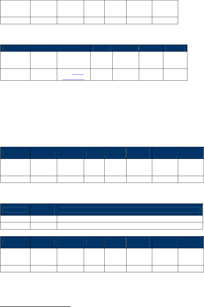
NEO Interface Developers Guide
236
Header Tag
& Protocol
Version
Command
Sub-
Command
Data
Length
(MSB)
Data
Length
(LSB)
CRC
(LSB)
CRC
(MSB)
ViVOtech2\0
84h
06h
00
00
Response Frame
Byte 0-9
Byte 10
Byte 11
Byte 12
Byte 13
Byte 14
Byte 15
Header Tag
& Protocol
Version
Command
Status
Data
Length
(MSB)
Data
Length
(LSB)
CRC
(LSB)
CRC
(MSB)
ViVOtech2\0
84h
See Status
Code Table 00 00
Get EMV Revocation List (84-07)
This command retrieves a sequence of consecutive records from the EMV
revocation list. The list may be retrieved in several command exchanges,
depending on the size specified in the command and the number of entries in
the list.
Command Frame
Byte 0-9 Byte 10 Byte 11 Byte 12
Byte 13
Byte 14 …
Byte13+n
Byte 14+n
Byte 15+n
Header Tag
& Protocol
Version
Command
Sub-
Command
Data
Length
(MSB)
Data
Length
(LSB)
Data CRC
(LSB)
CRC
(MSB)
ViVOtech2\0
84h
07h
00
00
The data field specifies the following information:
Offset
Length
(bytes) Data Description
00h
2
Size - maximum number of bytes to be retrieved (MSB first)
02h
2
Starting record4 (MSB first)
Response Frame
Byte 0-9 Byte 10 Byte 11 Byte 12
Byte 13
Byte 14 …
Byte13+n
Byte 14+n
Byte 15+n
Header Tag
& Protocol
Version
Command
Sub-
Command
Data
Length
(MSB)
Data
Length
(LSB)
Data CRC
(LSB)
CRC
(MSB)
ViVOtech2\0
84h
07h
00
00
The data field will contain the maximum number of records that can fit in the
size provided in the command. No partial records are returned. The maximum
4
For GR, this number must be less than 30. The first record is 0.
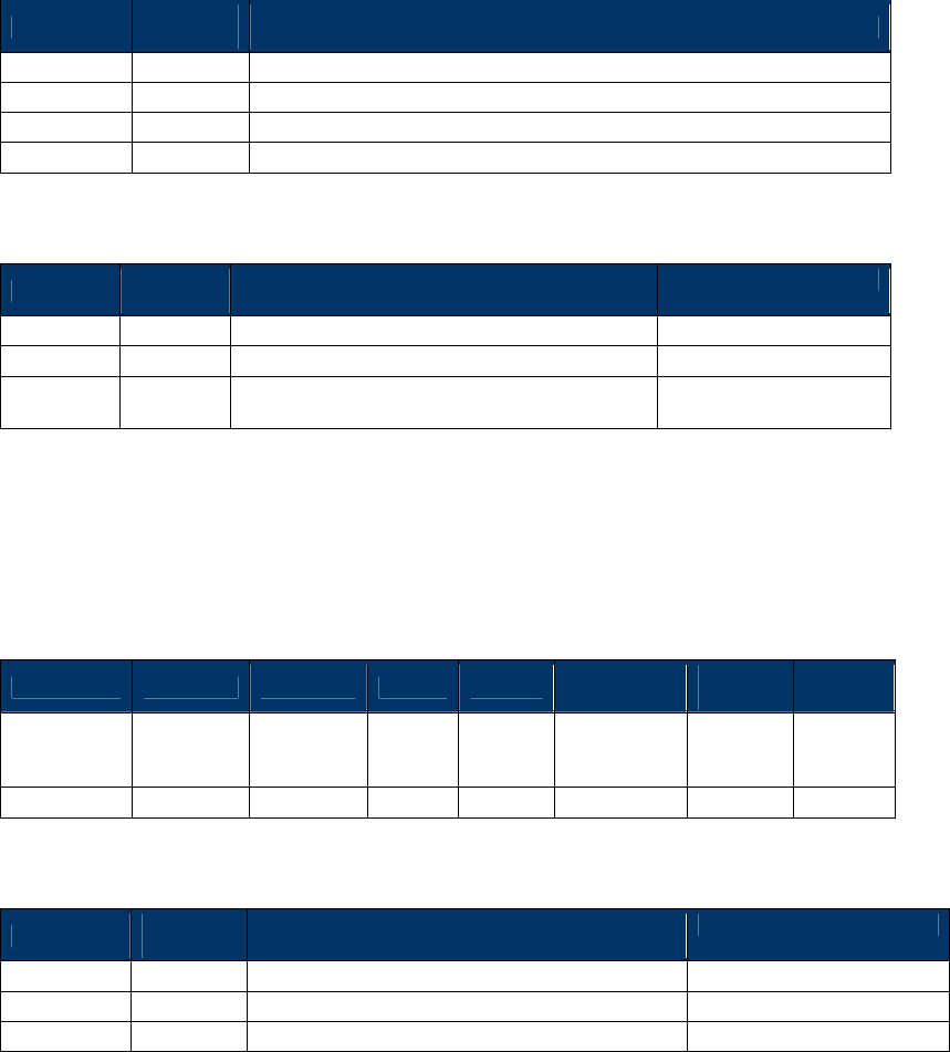
NEO Interface Developers Guide
237
size of data bytes that can be returned is 282 bytes (12 + 9 * size of a list
record).
The data field is formatted as follows:
Offset
Length
(bytes)
Data Description
00h
4
Number of records returned
04h
4
Number of records remaining in the file
08h
4
Record size
0Ch
varies
Revocation list records
Each record is formatted as follows:
Offset
Length
(bytes)
Data Description
Example
00h
5
RID (packed hex format)
A0 00 00 00 03
05h
1
Key Index (packed hex format)
FE
08h 3
Certificate Serial Number (packed hex
format)
00 10 00
Delete an Entry from EMV Revocation List (84-0D)
This command deletes a specific entry from the EMV revocation list. Unlike the
commands described previously, this command deletes the specific entry that
matches the RID, the key index, and the certificate serial number.
Command Frame
Byte 0-9 Byte 10 Byte 11 Byte 12
Byte 13
Byte 14 …
Byte13+n
Byte
14+n
Byte
15+n
Header Tag
& Protocol
Version
Command
Sub-
Command
Data
Length
(MSB)
Data
Length
(LSB)
Data CRC
(LSB)
CRC
(MSB)
ViVOtech2\0
84h
0Dh
00
09
The data field contains the information to select the EMV revocation list record:
Offset
Length
(bytes) Data Description
Example
00h
5
RID (packed hex format)
A0 00 00 00 04
05h
1
Key Index (packed hex format)
F8
06h
3
Certificate Serial Number (packed hex format)
00 10 01
Response Frame
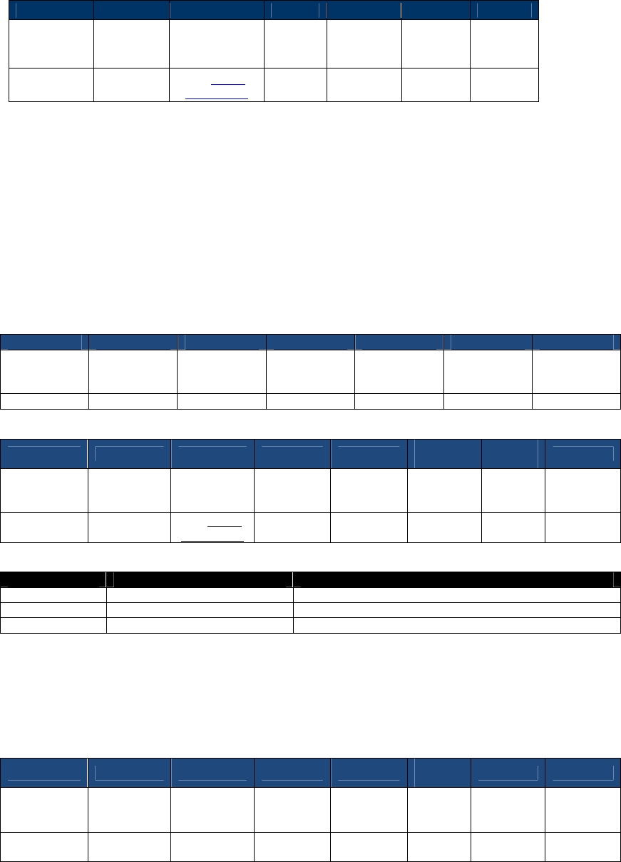
NEO Interface Developers Guide
238
Byte 0-9
Byte 10
Byte 11
Byte 12
Byte 13
Byte 14
Byte 15
Header Tag
& Protocol
Version
Command
Status
Data
Length
(MSB)
Data
Length
(LSB)
CRC
(LSB)
CRC
(MSB)
ViVOtech2\0
84h
See Status
Code Table 00 00
EMV Exception Log List Commands
Get EMV Exception Log Status (84-08)
This command returns information about the EMV exception log. The version number, record size, and
number of records contained in the file are returned.
Command Frame
Byte 0-9
Byte 10
Byte 11
Byte 12
Byte 13
Byte 14
Byte 15
Header Tag
&Protocol
Version
Command Sub-
Command
Data Length
(MSB)
Data Length
(LSB) CRC (LSB) CRC (MSB)
ViVOtech2\0
84h
08
00h
00h
Response Frame
Byte 0-9 Byte 10 Byte 11 Byte 12 Byte 13
Byte 14-
13+n
Byte
14+n
Byte 15+n
Header Tag
&Protocol
Version
Command Status Code
Data
Length
(MSB)
Data
Length
(LSB)
Data CRC
(LSB) CRC (MSB)
ViVOtech2\0
84h
See Status
Code Table
00h 0Ch
The data returned in a successful command contains the following information:
Offset
Length (bytes)
Description
00h
4
Version number
04h
4
Number of records
08h
4
Size of records
Add Entry to EMV Exception List (84-09)
This command adds an entry to the EMV exception list.
Command Frame
Byte 0-9 Byte 10 Byte 11 Byte 12 Byte 13
Byte 14-
25
Byte 26 Byte 27
Header Tag
&Protocol
Version
Command Sub-
Command
Data
Length
(MSB)
Data
Length
(LSB)
Data CRC (LSB)
CRC (MSB)
ViVOtech2\0
84h 09 00h 0Ch
See
Below
The exception list data is as follows:
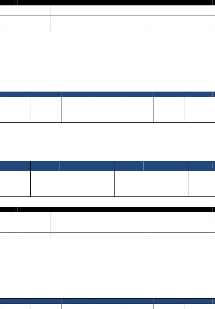
NEO Interface Developers Guide
239
Offset
Length (bytes)
Description
Example
00h
1
PAN logical length in bytes (packed hex
format). Must be <= 0Ah
08h
01h
10
PAN (packed hex format, padded with 'F' if
required)
5413339000001596FFFFh
0Bh
1
Sequence number (packed hex format)
00h
Example Exception List File Data (in a non-null terminated ASCII text file):
084761739001010010FFFF01085762739101010010FFFF0008112233445566778FFFFF050A112233445566778899
0F00
The above file has four entries:
08 4761739001010010FFFF 01 where PAN = 4761739001010010
08 5762739101010010FFFF 00 where PAN = 5762739101010010
08 112233445566778FFFFF 05 where PAN = 112233445566778
0A 1122334455667788990F 00 where PAN = 1122334455667788990
Response Frame
Byte 0-9
Byte 10
Byte 11
Byte 12
Byte 13
Byte 14
Byte 15
Header Tag
&Protocol
Version
Command Status Code
Data Length
(MSB)
Data Length
(LSB) CRC (LSB) CRC (MSB)
ViVOtech2\0
84h
See Status
Codes Table
00h 00h
Delete Entry from EMV Exception List (84-0A)
This command deletes an entry from the EMV exception list.
Command Frame
Byte 0-9 Byte 10 Byte 11 Byte 12 Byte 13
Byte 14-
25 Byte 26 Byte 27
Header Tag
&Protocol
Version
Command Sub-
Command
Data
Length
(MSB)
Data
Length
(LSB)
Data CRC (LSB)
CRC (MSB)
ViVOtech2\0
84h 0A 00h 0Ch
See
Below
The exception list data is as follows:
Offset
Length (bytes)
Description
Example
00h
1
PAN logical length in bytes (packed hex
format). Must be <= 0Ah
08h
01h
10
PAN (packed hex format, padded with 'F' if
required)
5413339000001596FFFFh
0Bh
1
Sequence number (packed hex format)
00h
Example Exception List File Data (in a non-null terminated ASCII text file):
084761739001010010FFFF01085762739101010010FFFF0008112233445566778FFFFF050A112233445566778899
0F00
The above file has four entries:
08 4761739001010010FFFF 01 where PAN = 4761739001010010
08 5762739101010010FFFF 00 where PAN = 5762739101010010
08 112233445566778FFFFF 05 where PAN = 112233445566778
0A 1122334455667788990F 00 where PAN = 1122334455667788990
Response Frame
Byte 0-9
Byte 10
Byte 11
Byte 12
Byte 13
Byte 14
Byte 15
Header Tag
Command
Status Code
Data Length
Data Length
CRC (LSB)
CRC (MSB)
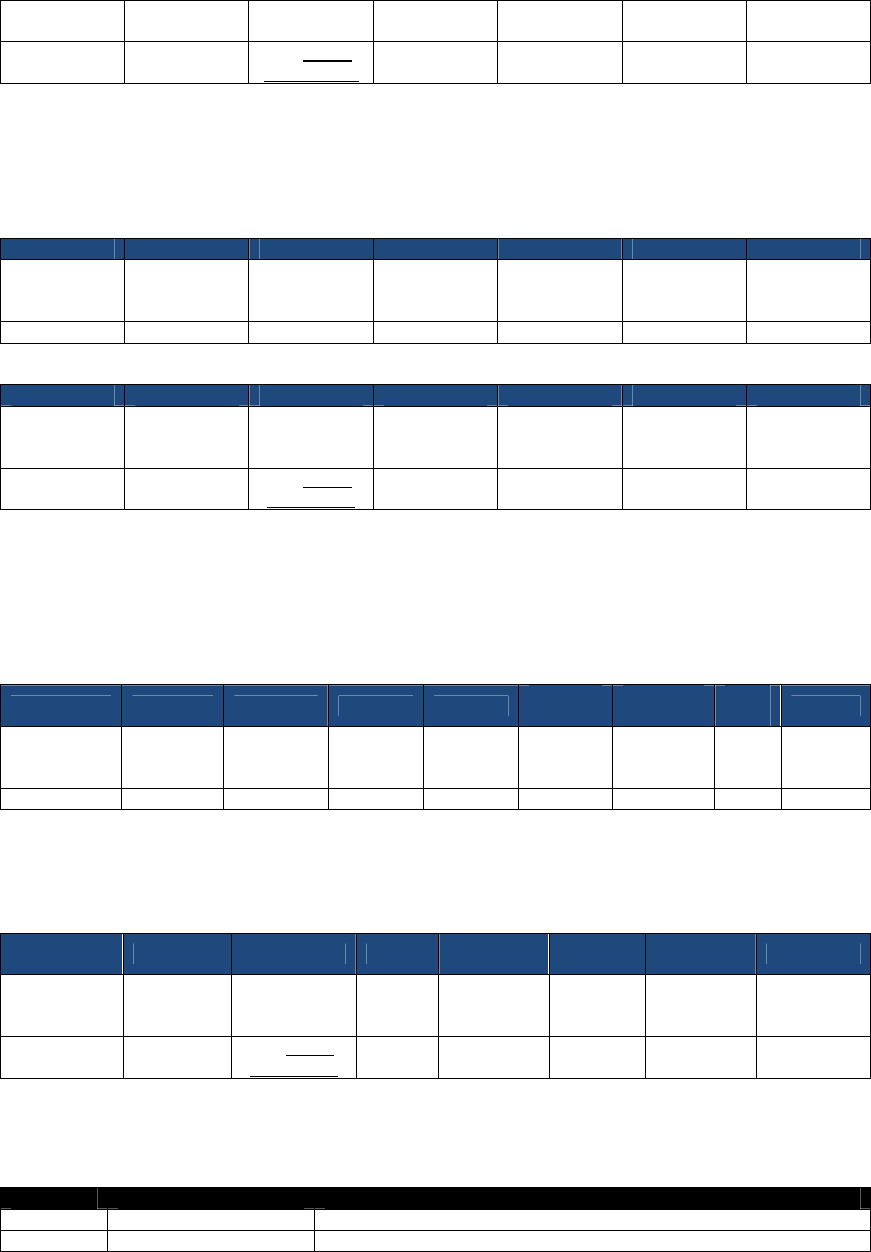
NEO Interface Developers Guide
240
&Protocol
Version
(MSB)
(LSB)
ViVOtech2\0
84h
See Status
Codes Table
00h 00h
Delete All Entries from EMV Exception List (84-0B)
This command deletes all entries from the EMV exception list.
Command Frame
Byte 0-9
Byte 10
Byte 11
Byte 12
Byte 13
Byte 14
Byte 15
Header Tag
&Protocol
Version
Command Sub-
Command
Data Length
(MSB)
Data Length
(LSB) CRC (LSB) CRC (MSB)
ViVOtech2\0
84h
0B
00h
00h
Response Frame
Byte 0-9
Byte 10
Byte 11
Byte 12
Byte 13
Byte 14
Byte 15
Header Tag
&Protocol
Version
Command Status Code
Data Length
(MSB)
Data Length
(LSB) CRC (LSB) CRC (MSB)
ViVOtech2\0
84h
See Status
Code Table 00h 00h
Get EMV Exception List (84-0C)
This command retrieves consecutive records from the EMV exception list.
Command Frame
Byte 0-9 Byte 10 Byte 11 Byte 12 Byte 13
Bytes 14-
15
Bytes 16-
17
Byte
18 Byte 19
Header Tag
&Protocol
Version
Command
Sub-
Command
Data
Length
(MSB)
Data
Length
(LSB)
Max
number
of bytes
Starting
Record
CRC
(LSB)
CRC
(MSB)
ViVOtech2\0
84h
0C
00h
04h
N
0-65535
The maximum number of byte is a 16-bit binary number, MSB first.
The starting record is the first record to be retrieved; expressed as a 16-bit binary number MSB first, value
from 0-65535.
Response Frame
Byte 0-9 Byte 10 Byte 11 Byte 12
Byte 13
Bytes 14-
13+n Byte 14+n
Byte 15+n
Header Tag
&Protocol
Version
Command
Status Code
Data
Length
(MSB)
Data
Length
(LSB)
Data CRC (LSB)
CRC (MSB)
ViVOtech2\0
84h
See Status
Code Table
The data returned is the maximum number of transaction records that satisfy the command constrains. The
nmber of bytes returned always is an integer multiple of the transaction record size(i.e., no partial records
are returned) plus 12 decimal bytes. The maximum number of data bytes that can be returned in a single
operation is limited to 4080 bytes.
Offset
Size in Bytes MSB First
Description
0
4
Number of records returned
4
4
Number of records remaining in file

NEO Interface Developers Guide
241
8
4
Record size
C
n-C
Exception list records
The format of an exception list record (as returned in the Response Data) is as follows:
Table 55: Exception List Record Format
Offset
Field
Length (bytes)
0
PAN Length (Logical)
1
1
PAN (right-padded with F if required)
10
11
PAN Sequence Number
1
An example of an exception list records returned by this serial command is given below (only
the data section of the response is given), along with an explanation.
Data Section of the Response Frame5 Explanation
08 47 61 73 90 01 01 00 10 FF FF 01
08 57 62 73 91 01 01 00 10 FF FF 00
08 11 22 33 44 55 66 77 8F FF FF 05
0A 11 22 33 44 55 66 77 88 99 0F 00
Rec 1: PAN = 4761739001010010
Rec 2: PAN = 5762739101010010
Rec 3: PAN = 112233445566778
Rec 4: PAN = 1122334455667788990
Generic Pass-through Commands
The commands in this section provide the most basic capability to communicate
directly with a PICC. They provide control of the polling process, and exchange
of application protocol data units (APDU). These commands may be used to
“extend” the capabilities of the ViVOpay reader to accept cards using
application protocols that are not currently supported in the reader firmware.
If the reader is not in Pass-Through mode, a “Pass-Through Mode Start”
command must first be issued. Otherwise, the commands in this section will
result in an error.
Pass-Through Mode Start/Stop (2C-01)
The Pass-Through Mode Start/Stop command is used to enter and exit Pass-Through Mode. The
ViVOpay reader can only accept Pass-Through commands when it is in Pass-Through Mode.
Command Frame
Byte 0-9
Byte 10
Byte 11
Byte 12
Byte 13
Byte 14
Byte 15
Byte 16
Header Tag
& Protocol
Version
Command
Sub-
Command
Data
Length
(MSB)
Data
Length
(LSB)
Data CRC (MSB)
CRC (LSB)
ViVOtech2\0
2Ch
01h
00h
01h
Mode
5
Spaces have been added in this example to increase readability; the space does not exist in the actual data. The data
exists as hex bytes.
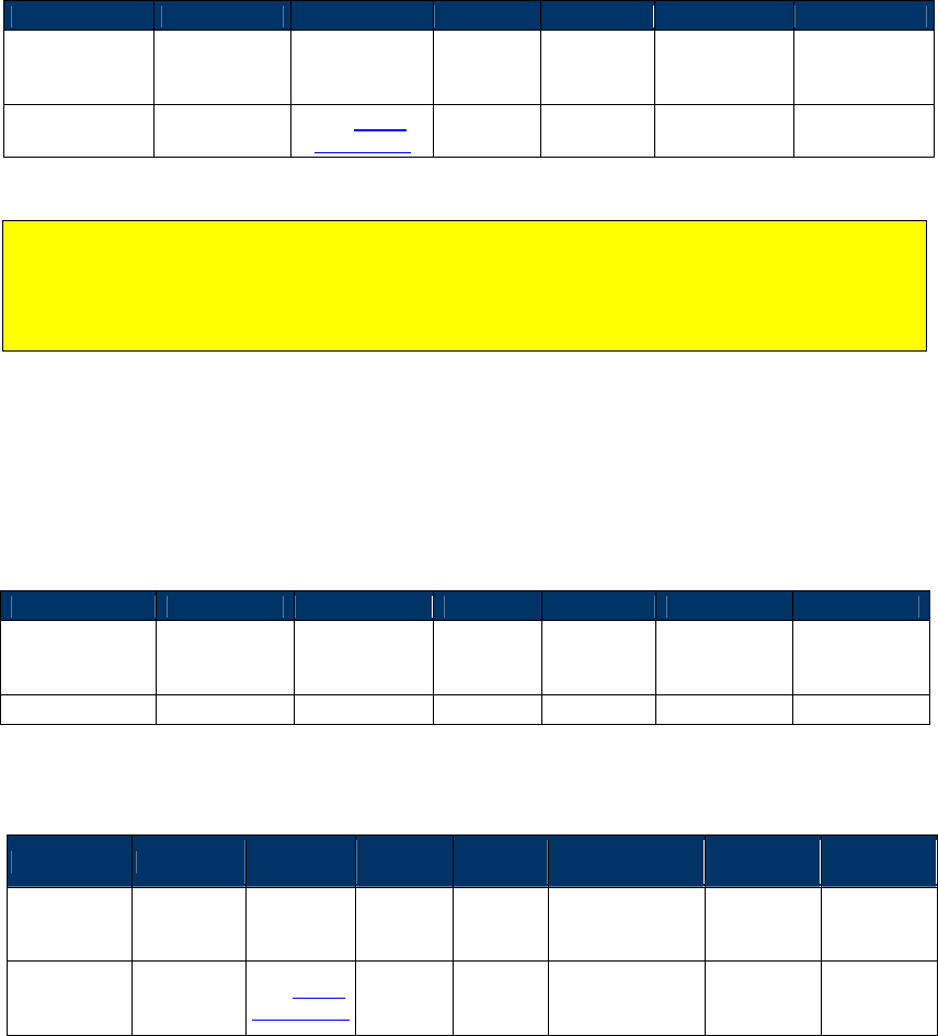
NEO Interface Developers Guide
242
Mode
0 = Stop Pass-Through
1 = Start Pass-Through
Response Frame
Byte 0-9
Byte 10
Byte 11
Byte 12
Byte 13
Byte 14
Byte 15
Header Tag &
Protocol
Version
Command Status Code
Data
Length
(MSB)
Data
Length
(LSB)
CRC (MSB) CRC (LSB)
ViVOtech2\0 2Ch
See Status
Code Table 00h 00h
The Pass-Through Mode Start command must be used to enter Pass-Through Mode.
The Pass-Through Mode Stop command can only be used in Pass-Through Mode. If the reader
is not in Pass-Through mode when the Pass-Through Mode Stop command is issued, the
reader will respond with an error.
Get PCD and PICC Parameters (2C-05)
This command allows the terminal to retrieve PCD and PICC related parameters from the
ViVOpay reader.
Command Frame
Byte 0-9
Byte 10
Byte 11
Byte 12
Byte 13
Byte 14
Byte 15
Header Tag &
Protocol
Version
Command Sub-
Command
Data
Length
(MSB)
Data
Length
(LSB)
CRC (MSB) CRC (LSB)
ViVOtech2\0
2Ch
05h
00h
00h
Response Frame
Byte 0-9 Byte 10 Byte 11 Byte 12
Byte 13
Byte 14 …
Byte 14+n-1 Byte 14+n
Byte 15+n
Header Tag
& Protocol
Version
Command
Status
Code
Data
Length
(MSB)
Data
Length
(LSB)
Data CRC (MSB)
CRC (LSB)
ViVOtech2\0
2Ch See Status
Code Table
00h
00h
or
0Fh
See Table below
If a valid Command Frame is received from the terminal, the ViVOpay reader retrieves the
parameters from the PCD and PICC. If the parameters are retrieved successfully, the reader
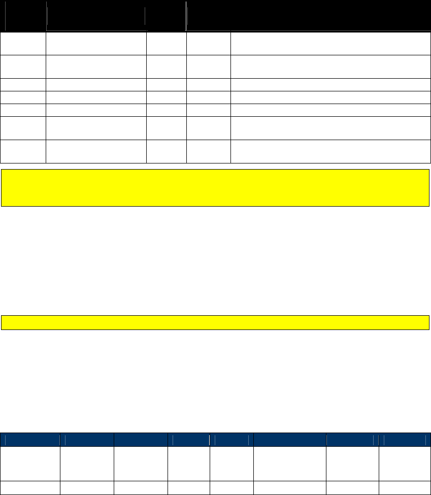
NEO Interface Developers Guide
243
returns a Response Frame with OK Status and Data containing the parameters given below. For
details on the parameters, refer to ISO 14443.
If the Command Frame contains any errors, or an error occurred while retrieving the parameters,
then the reader sends a Response Frame with an appropriate Status. No data is returned in this
case.
Data Fields for the Response Frame (if Status = OK)
Table 56: Get PCD and PICC Parameters Data Field
Data
Byte Name Length
(bytes) Format Notes
0-1 Reader Buffer Size 2 Binary
Reader RF Buffer Size stored as a big-endian
number.
2-3 Max PICC Frame Size 2 Binary
Maximum PICC Frame Size stored as a big-endian
number.
4
CID
1
Binary
CID
5
Block
1
Binary
Block Number.
6
CID Supported
1
Binary
CID Supported
7-10 FWT 4 Binary
Frame Waiting Time in ETUs. It is stored as a big-
endian number.
11-14 D-FWT 4 Binary
Delta FWT in ETUs. It is stored as a big-endian
number.
If you need to use these parameters, you should issue this command immediately after
issuing a “Poll for Token” command. This command simply reads the last parameters out of
the control block used to set parameters in the RF chip.
Poll for Token (2C-02)
Once Pass-Through Mode is started, ViVOpay will not poll for any cards until the “Poll for Token”
command is received. This command tells ViVOpay to start polling for a Type A or Type B PICC
until a PICC is detected or a timeout occurs.
This command automatically turns the RF Antenna on.
If a PICC is detected within the specified time limit, ViVOpay activates it and responds back to
the terminal with card related data such as the Serial Number.
If no PICC is detected within the specified time limit, ViVOpay stops polling and responds back
indicating that no card was found. No card related data is returned in this case.
Command Frame
Byte 0-9
Byte 10
Byte 11
Byte 12
Byte 13
Byte 14,15
Byte 16
Byte 17
Header Tag
& Protocol
Version
Command
Sub-
Command
Data
Length
(MSB)
Data
Length
(LSB)
Data CRC (MSB)
CRC (LSB)
ViVOtech2\0
2Ch
02h
00h
02h
See Below
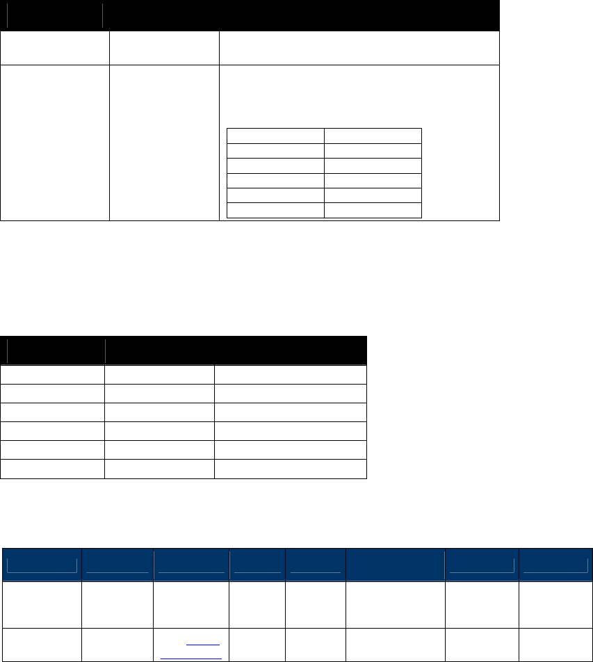
NEO Interface Developers Guide
244
Data Fields for the Command Frame
Table 57: Poll for Token Data Field for Command Frame
Data Field Length (bytes) Description
Timeout1
1
Time in Seconds Timeout1 cannot be zero
seconds if Timeout2 is Zero.
Timeout2
1
Multiplier for Time in multiples of 10
milliseconds.
Timeout2
Time in ms
0
0
1
10
2
20
:
:
255
2550
Together Timeout1 and Timeout2 are used by the ViVOpay reader to calculate the Timeout i.e.
the time to wait for a PICC. For example:
Table 58: Poll for Token Timeout
Timeout1 Timeout2 Timeout
0
0
Not Allowed
0
20
0 Seconds, 200 ms
0
50
0 Seconds, 500 ms
0
100
1 Second
1
0
1 Second
1
20
1 Second, 200 ms
Response Frame
Byte 0-9 Byte 10 Byte 11 Byte 12
Byte 13
Byte 14 … Byte
14+n-1
Byte 14+n
Byte 15+n
Header Tag
& Protocol
Version
Command
Status Code
Data
Length
(MSB)
Data
Length
(LSB)
Data CRC (MSB)
CRC (LSB)
ViVOtech2\0
2Ch
See Status
Code Table
00h Variable
below
The Data field contains data only if the Status Code is OK.

NEO Interface Developers Guide
245
Table 59: Poll for Token Data Field for Response Frame (Status Code is OK)
Data Field Length
(bytes)
Description
Card
1
Type of Card Found (or No Card Found).
00h None (Card Not Detected or Could not Activate)
01h ISO 14443 Type A (Supports ISO 14443-4 Protocol)
02h ISO 14443 Type B (Supports ISO 14443-4 Protocol)
03h Mifare Type A (Standard)
04h Mifare Type A (Ultralight)
05h ISO 14443 Type A (Does not support ISO 14443-4 Protocol)
06h ISO 14443 Type B (Does not support ISO 14443-4 Protocol)
07h ISO 14443 Type A and Mifare (NFC phone)
08h Felica
09h RCTIF Type B Prim
Serial
Number
0 or
Variable
Serial Number (or the UID) of the PICC. Length depends on the Card
Detected. If no card was detected, then a Serial Number is not returned.
Note: Most cards use a 4-byte UID, so the data field of the response is five (5) bytes long.
However, some cards with 7-byte UID’s have entered the market (for example, ViVOcard3)
and it is expected that cards with 10-byte UID’s will soon become available. All of these card
types are handled by this command.
Enhanced Poll for Token (2C-0C)
Once Pass-Through Mode is started, ViVOpay waits until the Poll for Token command is received.
This command tells ViVOpay to start polling for a Type A or Type B PICC until a PICC is detected
or a timeout occurs.
This command automatically turns the RF Antenna on.
Note: (For Kiosk III only) This command and Poll for Token command(2c-02) can be canceled
by command (05-01).for example:
1. Cancel Poll for Token command,
[TX] - 56 69 56 4F 74 65 63 68 32 00 2C 02 00 02 05 20 85 B8
[TX] - 56 69 56 4F 74 65 63 68 32 00 05 01 00 00 92 EF
[RX] - 56 69 56 4F 74 65 63 68 32 00 05 00 00 08 DF EF 36 04 00 07 00 00 77 FA
2. Cancel Enhanced Poll for Token command
[TX] - 56 69 56 4F 74 65 63 68 32 00 2C 0C 00 04 05 00 00 01 54 AB
[TX] - 56 69 56 4F 74 65 63 68 32 00 05 01 00 00 92 EF
[RX] - 56 69 56 4F 74 65 63 68 32 00 05 00 00 08 DF EF 36 04 00 07 00 00 77 FA
If a PICC is detected within the speified time limit, ViVOpay activates it and responds back to
the terminal with card related data, such as the Card Type and Serial Number (UID).
If no PICC is detected within the specified time limit, ViVOpay stops polling and responds back
indicating that no card was found. No card related data is returned in this case.
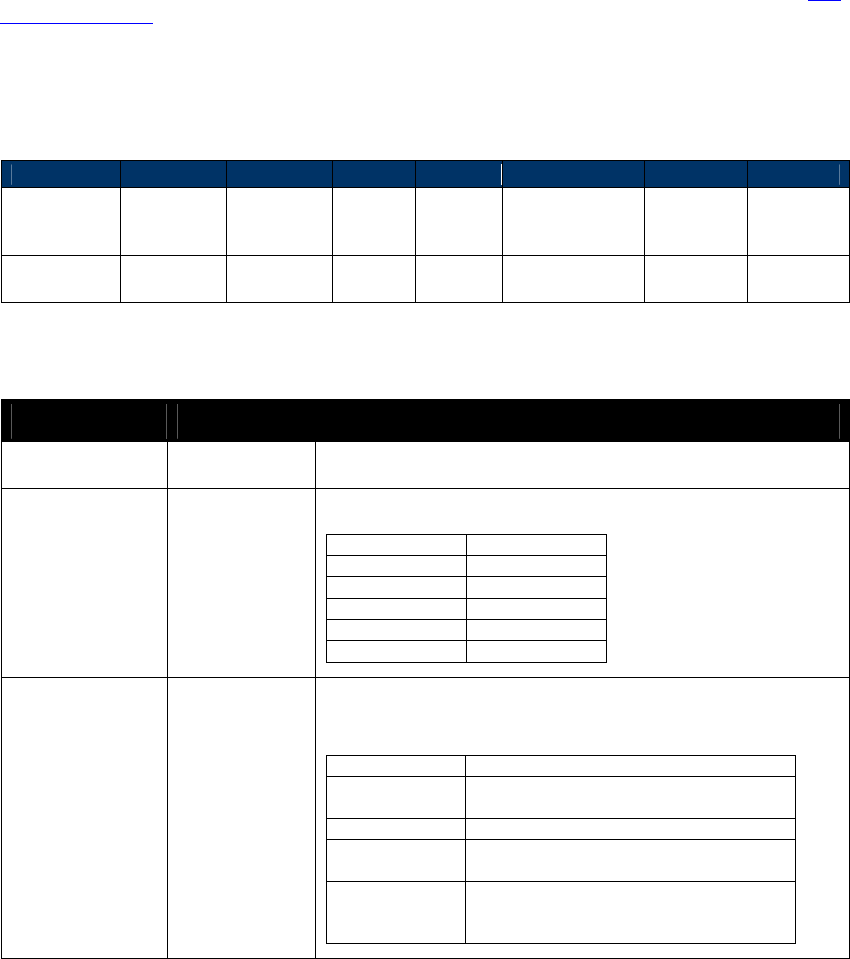
NEO Interface Developers Guide
246
9.1.1.2 Dual Application Cards
Some cards have more than one type of application stored on them. These are known as Dual
Application cards. At present, all these cards have an ISO-APDU compliant application as well as
a Mifare application.
To date, the only such supported dual application card is Card Type ‘07’, supporting ISO 14443
Type A, Mifare.
For normal ViVOpay transactions (i.e., not Pass-Through Mode), these cards are automatically
handled as ISO 14443 applications.
In Pass-Through Mode, the POS controls the polling mechanism. The POS can use a standard Poll
for Token (2C-02), where Card Type ‘07’ establishes a Mifare session.
Alternatively, the POS can issue an Enhanced Poll for Token (02-0C), where Card Type ‘07’ can
establish an ISO 14443 session.
Command Frame
Byte 0-9
Byte 10
Byte 11
Byte 12
Byte 13
Byte 14,15
Byte 16
Byte 17
Header Tag
& Protocol
Version
Command
Sub-
Command
Data
Length
(MSB)
Data
Length
(LSB)
Data CRC
(MSB)
CRC
(LSB)
ViVOtech2\0
2Ch 0Ch 00h 04h
See Table
Below
Table 60: Enhanced Poll for Token Data Field for Command Frame
Data Field Length (bytes) Description
Timeout1
1
Time in Seconds Timeout1 cannot be zero seconds if Timeout2 is
Zero.
Timeout2
1
Multiplier for Time in multiples of 10 milliseconds.
Timeout2
Time in ms
0
0
1
10
2
20
:
:
255
2550
Transaction Type 2
Initiate a transaction based upon the following masks (more than
1 can be active):
Mask (hex)
Action
00 01
Expect Card Type ‘07’
Force polling ISO 14443
00 02
PUPI Read deprecated by EMV 2.0
00 03
Force ISO 14443 Polling
Set Single PUPI Read
00 04
…
80 00
RFU – Reserved for Future Use
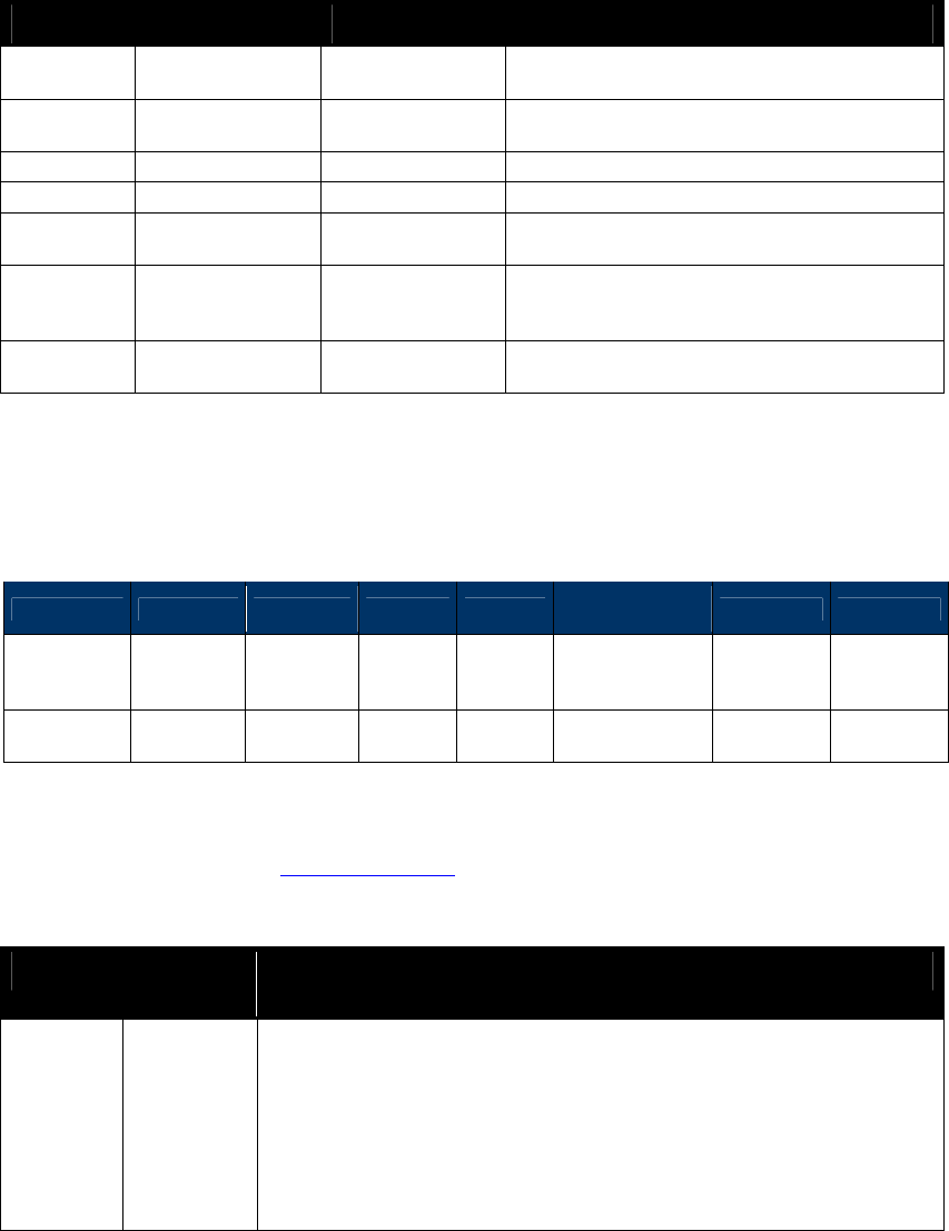
NEO Interface Developers Guide
247
Together Timeout1 & Timeout2 are used by the ViVOpay reader to calculate the Timeout, i.e.,
the time to wait for a PICC. For example:
Table 61: Enhanced Poll for Token Timeout
Timeout1 Timeout2 Transaction Type
Timeout
0 0 00 01
Not Allowed
Timeout error
0 20 00 01
0 Seconds, 200 ms
Force ISO 14443 polling
0
50
00 02
PUPI Read deprecated by EMV 2.0
0
100
00 00
1 Second
1 0 00 04
Not Allowed
Transaction Type Error
1 0 00 03
1 second
Force ISO 14443 Polling
Set Single PUPI Read
1 20 00 01
1 second
Force ISO 14443 Polling
Multiple Transaction Types in an Enhanced Poll for Token command are supported. That is, it is
possible to enable both Single PUPI Read and forced ISO 14443 polling simultaneously.
Response Frame
Byte 0-9 Byte 10 Byte 11 Byte 12
Byte 13
Byte 14 … Byte
14+n-1 Byte 14+n
Byte 15+n
Header Tag
& Protocol
Version
Command
Status
Code
Data
Length
(MSB)
Data
Length
(LSB)
Data CRC (MSB)
CRC (LSB)
ViVOtech2\0
2Ch
00 - OK
?? – Fail
00h Variable
See Table Below
The data field contains data only if the Status Code is OK (i.e., = 00h). For more information on
the status, please check the Status Code Table.
Table 62: Enhanced Poll for Token Data Field for Response Frame
Data Field Length
(bytes)
Description
Card
1
Type of Card Found (or No Card Found).
00h None (Card not detected or could not activate)
01h ISO 14443 Type A (Supports ISO 14443-4 protocol)
02h ISO 14443 Type B (Supports ISO 14443-4 protocol)
03h Mifare Type A (Standard)
04h Mifare Type A (Ultralight)
05h ISO 14443 Type A (Does not support ISO 14443-4 protocol)
06h ISO 14443 Type B (Does not support ISO 14443-4 protocol)
07h ISO 14443 Type A and Mifare (NFC phone)
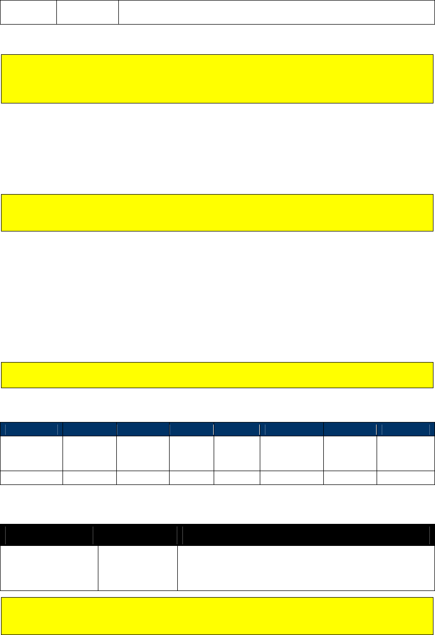
NEO Interface Developers Guide
248
Serial
Number
0 or
Variable
Serial number (or the UID) of the PICC. Length depends on the card
detected. If no card was detected, then a serial number is not returned.
Note: Most cards use a 4-byte UID, so the data field of the response is five (5) bytes long.
However, some cards with 7-byte UID’s have entered the market (for example, ViVOcard3)
and it is expected that cards with 10-byte UID’s soon becomes available. All of these card
types are handled by this command.
9.1.1.3 Enhanced Poll for Token Usage
This command can be substituted for the standard Poll for Token in any transaction taking
place in Pass-Through Mode. Its differences in operation are noted as above; its other arguments
should be identical to those of the standard Poll for Token that it replaces.
Note: If you use an Enhanced Poll for Token command but have set all values in the
Transaction Type field to zero, then the command performs a standard Poll for Token
instead.
Get ATR (2C-12)
This pass-through command can be used to get the ATR received by the reader from the SAM
when a Level 1 session was established. This command applies to the SAM interfaces
(SAM1/SAM2).
Before this pass-through command can be used, a Level 1 session must have been established on
the contact interface to be used through the Enhanced Pass-through command (Poll for Token
single shot command).
Note: SAM interface is only supported in SRED devices. It is not supported in non-SRED
versions.
Command Frame
Byte 0-9
Byte 10
Byte 11
Byte 12
Byte 13
Byte 14
Byte 15
Byte 16
Header Tag
& Protocol
Version
Command
Sub-
Command
Data
Length
(MSB)
Data
Length
(LSB)
Data CRC (LSB)
CRC
(MSB)
ViVOtech2\0
2Ch
12h
00h
01h
Interface
Command Data
Data Item Length (bytes) Description/Example
Interface 1
Allowed interfaces for which to get the ATR.
00h = retrieve last ATR received from PICC
21h = SAM1 (SRED version only)
22h = SAM2 (SRED version only)
If a 21h or 22h is specified in the Data Field for any ViVOpay reader other than the VP5500,
the result will be the same as if a 00h was specified. That is, any GetATR command only
returns the last ATR received from the PICC.
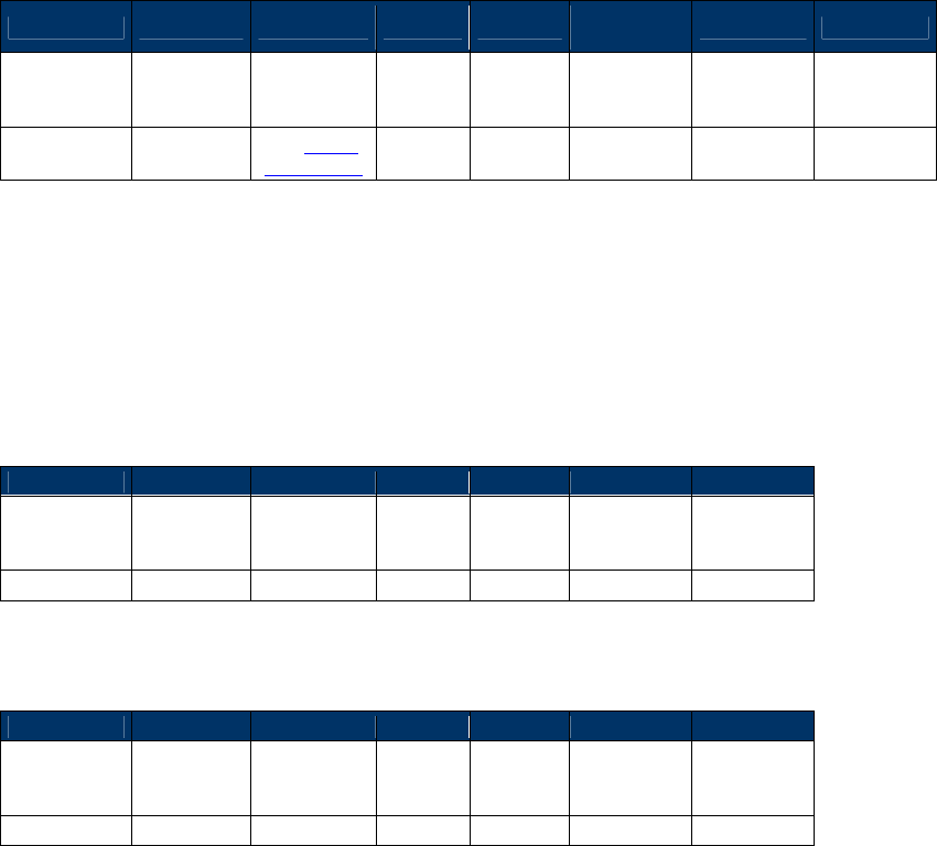
NEO Interface Developers Guide
249
Response Frame
Byte 0-9 Byte 10 Byte 11 Byte 12
Byte 13
Byte 14 …
Byte 14+n-1
Byte 14+n
Byte 15+n
Header Tag
& Protocol
Version
Command
Status Code
Data
Length
(MSB)
Data
Length
(LSB)
Data
CRC (MSB)
CRC (LSB)
ViVOtech2\0
2Ch
See Status
Code Table
00h variable
ATR
Terminate ISO Session (2C-16)
Traditionally, pass-through sessions have been terminated by dropping the RF field. However,
the RCTIF test specification requires a graceful termination of a session, using either a DISC
(Bprime) or a DESELECT (A and B).
The TerminateISOSession command send the appropriate command to disconnect the session. It
will wait for the requisite timeout period, reset the field and then return a status.
Byte 0-9
Byte 10
Byte 11
Byte 12
Byte 13
Byte 14
Byte 15
Header Tag
& Protocol
Version
Command
Sub-
Command
Data
Length
(MSB)
Data
Length
(LSB)
CRC (MSB)
CRC (LSB)
ViVOtech2\0
2Ch
16h
00h
00h
The response frame is a simple confirmation that the session has been terminated. The field is
left in the desired state.
Byte 0-9
Byte 10
Byte 11
Byte 12
Byte 13
Byte 14
Byte 15
Header Tag
& Protocol
Version
Command
Status Code
Data
Length
(MSB)
Data
Length
(LSB)
CRC (MSB)
CRC (LSB)
ViVOtech2\0
2Ch
varies
00h
00h
The status returned indicates:
0 = any existing session was terminated.
1 = no session was active (however the field will always be reset)
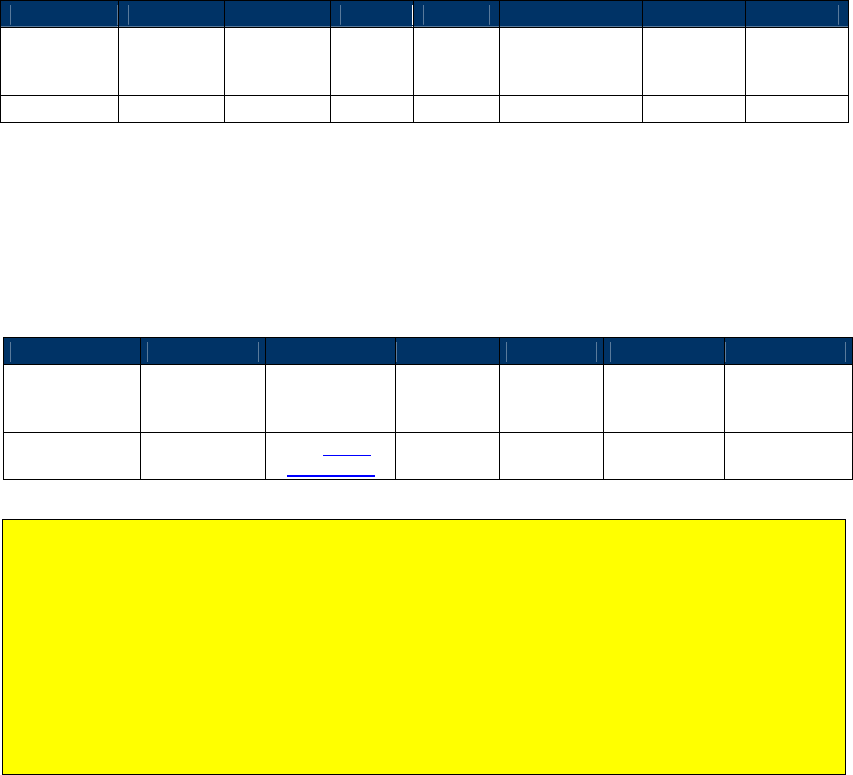
NEO Interface Developers Guide
250
Antenna Control (28-01)
This command turns the RF Antenna ON or OFF.
Command Frame
Byte 0-9
Byte 10
Byte 11
Byte 12
Byte 13
Byte 14
Byte 15
Byte 16
Header Tag
& Protocol
Version
Command
Sub-
Command
Data
Length
(MSB)
Data
Length
(LSB)
Data CRC
(MSB)
CRC
(LSB)
ViVOtech2\0
28h
01h
00h
01h
Mode
Mode:
0 = Disable RF Antenna
1 = Enable RF Antenna
Response Frame
Byte 0-9
Byte 10
Byte 11
Byte 12
Byte 13
Byte 14
Byte 15
Header Tag &
Protocol
Version
Command Status Code
Data
Length
(MSB)
Data
Length
(LSB)
CRC (MSB) CRC (LSB)
ViVOtech2\0 28h
See Status
Code Table 00h 00h
Warnings on use of Antenna Off command:
Turning off the antenna deactivates the RF field and returns the card to a Power Off state,
terminating any existing connection. A new “Poll for Token” command would need to be
issued to establish a new conversation with a card. Turning the antenna off and then turning
it back on is a useful way to reset the card to its Idle State where it will respond to polling
commands.
When exiting Pass-Through Mode, if the ViVOpay reader is returning to Auto Poll mode, it is
advised to issue an “Antenna Control Enable RF Antenna” command before exiting to ensure
the antenna is in the right state.
Pass-through UI Control
LED Control (0A-02)
This command switches the specified ViVOpay LEDs off or on only when ViVOpay is in Pass-
Through Mode.
NEO Interface Developers Guide
251
Command Frame
Byte 0-9
Byte 10
Byte 11
Byte 12
Byte 13
Byte 14,15
Byte 16
Byte 17
Header Tag
& Protocol
Version
Command
Sub-
Command
Data
Length
(MSB)
Data
Length
(LSB)
Data CRC (MSB)
CRC (LSB)
ViVOtech2\0
0Ah
02h
00h
02h
below
Table 63: LED Control Data Field
Data Field Length
(bytes)
Description
LED#
1
00h: LED 0 (Power LED)
01h: LED 1
02h: LED 2
03h: LED 3
FFh: All 4 LEDs
Where the LEDs are numbered 0, 1, 2, 3 counting from the left.
Note: If you are using pass-through mode to control the Power LED (LED
0), it is your responsibility to make sure that it behaves correctly.
LED Status
1
00h: LED Off
01h: LED On
Response Frame
Byte 0-9
Byte 10
Byte 11
Byte 12
Byte 13
Byte 14
Byte 15
Header Tag &
Protocol
Version
Command Status Code
Data
Length
(MSB)
Data
Length
(LSB)
CRC (MSB) CRC (LSB)
ViVOtech2\0 0Ah
See Status
Code Table
00h 00h
Buzzer Control (0B-xx)
This command can be used to sound the ViVOpay Buzzer.
Command Frame
Byte 0-9
Byte 10
Byte 11
Byte 12
Byte 13
Byte 14
Byte 15
Byte 16
Header Tag
& Protocol
Version
Command
Sub-
Command
Data
Length
(MSB)
Data
Length
(LSB)
Data CRC (MSB)
CRC (LSB)
ViVOtech2\0
0Bh See Below
00h 01h
Buzzer
Parameter
Sub-Command = 01h N Short Beeps
= 02h Single Long Beep of Specified Duration
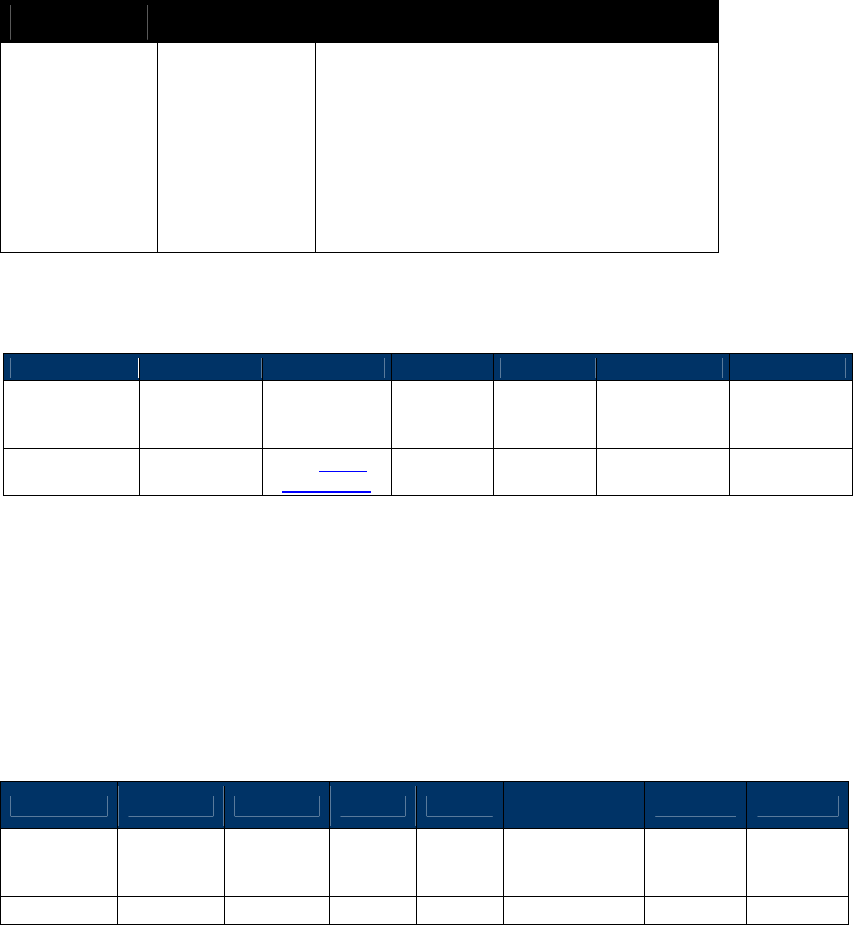
NEO Interface Developers Guide
252
Table 64: Buzzer Control Data Field
Data Field Length (bytes) Description
Buzzer
Parameter
1
If Sub-Command is Short Beeps …
Num Beeps = 01h One Short Beep
= 02h Two Short Beeps
= 03h Three Short Beeps
= 04h Four Short Beeps
If Sub-Command is Long Beep …
Duration = 00h 200 ms
= 01h 400 ms
= 02h 600 ms
= 03h 800 ms
Response Frame
Byte 0-9
Byte 10
Byte 11
Byte 12
Byte 13
Byte 14
Byte 15
Header Tag &
Protocol
Version
Command Status Code
Data
Length
(MSB)
Data
Length
(LSB)
CRC (MSB) CRC (LSB)
ViVOtech2\0 0Bh
See Status
Code Table 00h 00h
Pass-through Data Exchange
Exchange Contactless Data (2C-03)
This command allows the terminal to send, via ViVOpay, application-level APDUs to a PICC that
supports ISO 14443-4 Protocol. The PICC response is sent back by ViVOpay to the Terminal.
Command Frame
Byte 0-9 Byte 10 Byte 11 Byte 12
Byte 13
Byte 14 …
Byte 14+n-1 Byte 14+n
Byte 15+n
Header Tag
& Protocol
Version
Command
Sub-
Command
Data
Length
(MSB)
Data
Length
(LSB)
Data CRC (MSB)
CRC (LSB)
ViVOtech2\0
2Ch
03h
Variable
Variable
APDU Out
APDU Out is the complete APDU that is to be sent to the PICC. The contents of the APDU depend
on the application residing on the PICC and are out of the scope of this document.
If a valid Command Frame is received from the terminal, ViVOpay sends the APDU data to the
PICC and receives its response. ViVOpay treats the PICC response as unknown data and does not
try to interpret it. If the operation was successful, ViVOpay returns a Response Frame with an
OK status and the response received from the PICC (APDU response).
If the Command Frame contains any errors, or an error occurred during communication with the
PICC, then ViVOpay sends a Response Frame with an appropriate Status. No Data is returned in
this case.

NEO Interface Developers Guide
253
Response Frame
Byte 0-9 Byte 10 Byte 11 Byte 12
Byte 13
Byte 14 …
Byte 14+n-1
Byte 14+n
Byte 15+n
Header Tag
& Protocol
Version
Command
Status Code
Data
Length
(MSB)
Data
Length
(LSB)
Data CRC (MSB)
CRC (LSB)
ViVOtech2\0
2Ch See Status
Code Table
Variable
Variable
APDU response
Or
None
The Data field contains data only if the Status Code is OK. In this case, the data consists of
“APDU Response” i.e. the response data that was received from the PICC. The contents of the
response depend on the application residing on the PICC and are out of the scope of this
document.
For SRED device, the APDU data being received from the card/device by the reader will be
checked for sensitive data elements using rule in “Secure Pass-Through Function”. If found, and
it has not been established that this transaction belongs to an AID or BIN on the White List, the
Command will return a Parameter Not Supported error (0x06).
PCD Single Command Exchange (2C-04) Protocol 2
This command allows the terminal to send, via the ViVOpay reader, raw data to an ISO 14443
PICC that does not support ISO 14443-4 Protocol (such as Mifare Standard or Mifare Ultralight).
The PICC response is sent back by the reader to the terminal.
Command Frame
Byte 0-9 Byte 10 Byte 11 Byte 12
Byte 13
Byte 14 …
Byte 14+n-1 Byte 14+n
Byte 15+n
Header Tag
& Protocol
Version
Command
Sub-
Command
Data
Length
(MSB)
Data
Length
(LSB)
Data CRC (MSB)
CRC (LSB)
ViVOtech2\0
2Ch 04h Variable
Variable
See Table
below
Table 65: PCD Single Command Exchange Data Field Protocol 2
Data Field Length
(bytes)
Description
PCD Command
1
This is the command that is sent to the PCD Reader IC on the ViVOpay
board. It tells the PCD what to do with the data sent with the
command. The PCD commands supported and their values are given in
the “PCD Cmd” Table below
PCD Timeout
4
This is the RF communication timeout in ETUs stored as a 4-byte big-
endian number, where 1 ETU is 9.44 microseconds. The RF
communication timeout guards the communication between the PCD
reader IC and the PICC Card. The timeout is measured between the
last bit sent to the PICC and the first bit received from the PICC.

NEO Interface Developers Guide
254
Data Field Length
(bytes)
Description
PCD Command
Flags
1
These flags allow greater control over the way ViVOpay processes the
command via the PCD Reader IC. Format of the PCD Command Flags
byte is given in the “PCD Command Flags” Table below.
Channel
Redundancy
Register
1
This value tells the PCD what data integrity checks to perform during
communication with the PICC Card. The checks to perform at each
stage are defined by the protocol (14443 Type A or B). The format of
the PCD Command Flags byte is given in the “Channel Redundancy
Register” Table below.
Raw Data Out
Variable
Raw data that is sent to the PICC or to the PCD.
The Command Frame contains some PCD parameters and raw data. The PCD Command
Parameter is used by ViVOpay to determine what PCD function is to be carried out. The raw
data is sent to the PICC for the Transceive command, or is used for LoadKey/Authentication.
The contents of the data depend on the PICC and PCD and are out of the scope of this document.
Table 66: PCD Commands Protocol 2
PCD Command Value Description
PCD LOADKEY
19h
Used for Loading Mifare Key into PCD for Authentication
PCD AUTHENTICATE1 0Ch
Used for PCD-based Mifare Authentication. This command
results in both Level 1 and Level 2 authentication being
performed automatically.
PCD TRANSCEIVE
1Eh
Used to Send/Receive raw Data to/from the PICC
Note: The PCD LOADKEY and PCD AUTHENTICATE1 functions may also be performed by the
terminal directly by using the PCD Transceive Command.
PCD Command Flags Table
Bit# Flag Value Meaning
0
Disable DF
(DF=Disturbance
Filter)
1
When response from PICC Card has been received, end of
response is signaled regardless of errors.
0
When response from PICC Card has been received, if there
are errors then the data received is flushed and we continue
to receive.
If there are no errors then end of response is signaled.
1 Flush FIFO
1
PCD FIFO is flushed before starting this PCD command.
0
PCD FIFO is not flushed before starting this command.
2-4 TxLastBits 000
~111
Used for transmission of bit oriented frames: TxLastBits
defines the number of bits of the last byte that shall be
transmitted.
A 000 indicates that all bits of the last byte shall be
transmitted.
After transmission, TxLastBits is cleared automatically.
5 DISABLE 1 Disable
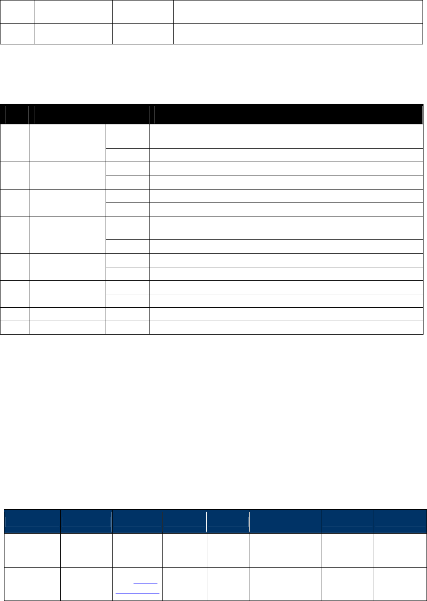
NEO Interface Developers Guide
255
RXMULTIPLE
FILTER 0 Enable(Default)
6-7 RFU 00 Reserved for future use.
Note: The definition of bit 5 is only to keep compatible with Kiosk II, it doesn't work, but this bit
is occupied, and is not allowed for other usage.
Table 67: PCD Channel Redundancy Register Protocol 2
Bit#
Flag Value Meaning
0 Parity Enable 1
Parity bit inserted in transmitted data and expected in received
data.
0
No parity bit inserted or expected.
1 Parity Odd
1
Odd parity.
0
Even parity.
2 Tx CRC Enable
1
CRC Bytes appended to transmitted data.
0
CRC Bytes not appended to transmitted data.
3 Rx CRC Enable 1
Last bytes of received data are interpreted as CRC bytes.
Note: The CRC is not sent back to the terminal by ViVOpay.
0
No CRC expected.
4 CRC-8
1
8-Bit CRC calculated.
0
16-Bit CRC calculated.
5 CRC 3309
1
CRC-Calculation is done according to ISO /IEC3309 (ISO 14443B).
0
CRC-Calculation is done according to ISO 14443A.
6
RFU
0
Must always be zero.
7
RFU
0
Must always be zero.
If a valid Command Frame is received from the terminal, ViVOpay sends the data to the PICC (or
carries out the appropriate action) and receives the PICC response. The ViVOpay reader treats
the response as unknown data and does not try to interpret it. If there is no error, the reader
returns a Response Frame with OK Status and the Data received from the PICC (if any). The
Response Frame also contains the result of the PCD Command (PCD Status). The PCD Status may
indicate success or an Error Code.
If the Command Frame contains any errors, or an error occurred during communication with the
PICC (such as PICC removed from the field), then the reader sends a Response Frame with an
appropriate Status. No Data is returned in this case.
Response Frame
Byte 0-9 Byte 10 Byte 11 Byte 12
Byte 13
Byte 14 …
Byte 14+n-1
Byte 14+n
Byte 15+n
Header Tag &
Protocol
Version
Command
Status Code
Data
Length
(MSB)
Data
Length
(LSB)
Data CRC (MSB)
CRC (LSB)
ViVOtech2\0
2Ch See Status
Code Table
Variable
Variable
See Table below
OR
None

NEO Interface Developers Guide
256
Table 68: PCD Single Command Exchange Data Field for Response
Data Field Length (bytes) Description
PCD Status
1
This field contains the result of the PCD Command. Possible values
are given in the following table.
PCD Status
Description
0
OK
-1
No Tag Error (Card not present)
-2
CRC Error
-3
Empty
-4
Authentication Error
-5
Parity Error
-6
Code Error
-7
Card Type Error
-8
Serial Number Error
-9
Key Error
-10
Authentication not carried out for this
Sector
-11
Bit Count Error
-12
Byte Count Error
-13
Idle
-15
Write Error
-18
Read Error
-19
FIFO Overflow Error
-21
Framing Error
-22
Access Error
-23
Unknown Command
-24
Collision Error
-25
Reset Error
-27
Access Timeout
-31
Coding Error
-54
Baud rate not supported by PCD
-112
Receive Buffer Overflow
RcvdBits
4
Number of bits received (stored as a big-endian number)
Raw Data In
0 or
Variable
The response data that is received from the PICC. The contents of
the response depend on the application residing on the PICC and
are out of the scope of this document.
For SRED device, the Raw Data being received from the card/device by the reader will be
checked for sensitive data elements using rule in “Secure Pass-Through Function”. If found, and
it has not been established that this transaction belongs to an AID or BIN on the White List, the
Command will return a Parameter Not Supported error (0x06).
9.1.1.4 Example: Sending a HALTA Command to a Type A PICC
Assuming that ViVOpay has been put into Pass-Through Mode, a Type A PICC has been detected
using the Poll for Token command, and the terminal application has completed the transaction
with the card, an ISO 14443 HALTA command can be sent to the PICC using the PCD Single
Command Exchange command. Given below is a log of the command and data that the terminal
would send to ViVOpay and also the responses that may be received from ViVOpay.

NEO Interface Developers Guide
257
The following serial data may be exchanged between a terminal/PC and a ViVOpay reader:
Table 69: Halt a Command Exchange Between Terminal/PC and Reader
Terminal
ViVOpay
Command Frame (“PCD Single Command
Exchange”, PcdTransceive, 106 ETUs,
[FlushFiFO=0, DisableDF=0], ChanRedReg=07)
“ViVOtech2\0” 2Ch 04h 00h 09h 1Eh 00h 00h
00h 6Ah 00h 07h 50h 00h <CRC><CRC>
Response Frame (OK, NoTagError, RcvdBits=0)
“ViVOtech2\0” 2Ch 00h 00h 05h FFh 00h 00h 00h
00h <CRC><CRC>
High Level Halt Command (2C-09)
This command instructs the ViVOpay reader to send a HALT command to the card and can be
used for any Type A or Type B card. This command can only be used once the reader has been
put in Pass-Through mode and the “Poll for Token” command has indicated that a Card is
present.
Command Frame
Byte 0-9
Byte 10
Byte 11
Byte 12
Byte 13
Byte 14
Byte 15
Byte 16
Header Tag &
Protocol
Version
Command
Sub-
Command
Data
Length
(MSB)
Data
Length
(LSB)
Data CRC (MSB)
CRC (LSB)
ViVOtech2\0
2Ch
09h
00h
01h
Card Type
Card Type:
0x01 = Type A
0x02 = Type B
Response Frame
Byte 0-9
Byte 10
Byte 11
Byte 12
Byte 13
Byte 14
Byte 15
Header Tag &
Protocol Version
Command Status Code
Data Length
(MSB)
Data Length
(LSB)
CRC (MSB)
CRC (LSB)
ViVOtech2\0 2Ch
See Status
Code Table
00h 00h
Enhanced Pass-Through Command (2C-0B)
This command instructs the reader to carry out several tasks while in Pass-Through Mode. This
command is ONLY enabled in Pass-Through Mode. If the reader is not in Pass-Through Mode, the
reader ignores this command.

NEO Interface Developers Guide
258
Note: SAM interface is only supported in SRED devices. It is not supported in non-SRED
version.
This command is used in three basic situations:
1. To initiate a pass-through transaction
2. To terminate a “successful” transaction
3. To terminate a “failed” transaction
This command is based in large part on the standard Set Message Led/Buzz command. It differs
primarily in that:
Activation/Deactivation of interface
Turn On/Off Antenna (PICC)
Single-shot command processing
Poll for Token (PICC/ICC/SAM)
Sound the buzzer in various ways
Turn on or off any of the LED’s
Write text and amount messages to the display
If this command is only used to set the Buzzer/LED then it works on the all readers.
There are three cases depending on the LCD Message index number:
Index 00h to 07h messages are directly display by the reader. Normally these messages are not
set through this command.
Index 08h to 0Bh messages can be set by the terminal.
Index FFh indicates the terminal is setting LED/Buzzer only.
Command Frame
Byte 0-9 Byte 10 Byte 11 Byte 12
Byte 13
Byte 14 …
Byte 14+n-1
Byte 14+n
Byte 15+n
Header Tag
& Protocol
Version
Command
Sub-
Command
Data
Length
(MSB)
Data
Length
(LSB)
Data CRC (LSB)
CRC (MSB)
ViVOtech2\0
2Ch 0Bh
07 + N
OR
7 + X + Y
See Data Table
The format and contents of the data field in the Command Frame are given in the following
table.

NEO Interface Developers Guide
259
Table 70: Enhanced Pass-Through Data Field
Data Item
Length
(bytes) Description
Single-Shot
Commands
1
This bitmask contains the following commands. If a bit is set (1), the
command is issued by the reader in the proper order. If the command
mask is cleared (0), the command is NOT executed.
0000 0001 : Activate Interface (mutually exclusive)
0000 0010 : Deactivate Interface (mutually exclusive)
0000 0100 : Issue Poll For Token
0000 1000 : Use Independent LED instead (mutually exclusive)
0001 0000 : Use Independent Buzzer instead (mutually exclusive )
0010 0000 : Use Specified Interface
0100 0000 : Reserved
1000 0000 : Reserved
For more information see Single-Shot Commands below.
LCD Message
Index (for
readers with a
display only)
1
00-07 is controlled by the reader and normally not set by this command
00: Idle Message (Welcome)
01: Present card (Please Present Card)
02: Time Out or Transaction Cancel (No Card)
03: Transaction between reader and card is in the middle
(Processing…)
04: Transaction Pass (Thank You)
05: Transaction Fail (Fail)
06: Amount (Amount $ 0.00 Tap Card)
07: Balance or Offline Available funds (Balance $ 0.00)
08-0B is controlled by the terminal through this command
08: Insert or Swipe card (Use Chip & PIN)
09: Try Again(Tap Again)
0A: Indicate the custom to present only one card (Present 1 card
only)
0B: Indicate the custom to wait for authentication/authorization
(Wait)
80 MASK – indicates the User has included a String1 character string to
be displayed with the standard message. If 0x80 is present, then the
message index (in the lower portion of the byte) is displayed and LCD
String1 and LCD String2 are only used for the Amount and Balance
messages.
FF indicates not to set the LCD message which allows terminal to set
LED/Buzzer only.
EXAMPLE 1: Index = 00h, reader displays standard “Welcome”
EXAMPLE 2: Index = 86h, reader displays standard 06h “Amount”
message but also displays String1 (in this case String1 = “$3.95”)
Beep Indicator 1
00h: No beep
01h: Single beep
02h: Double beep
03h: Three short beeps
04h: Four short beeps
05h One long beep of 200 ms
06h One long beep of 400 ms
07h One long beep of 600 ms
08h One long beep of 800 ms
LED Number 1
00h: LED 0 (Power LED)
01h: LED 1
02h: LED 2
03h: LED 3
FFh: All LEDs
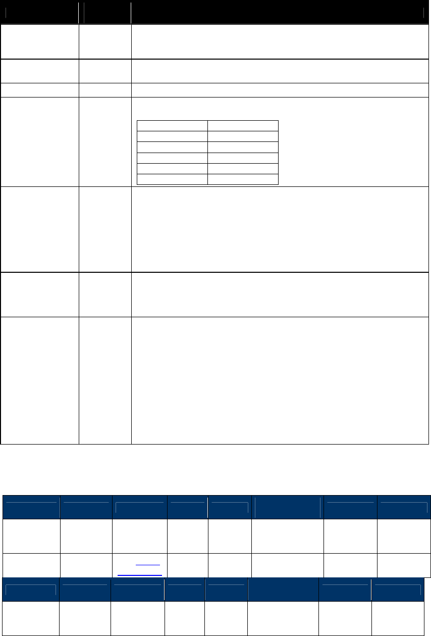
NEO Interface Developers Guide
260
Data Item
Length
(bytes) Description
Where the LEDs are numbered 0, 1, 2, 3 counting from the left.
Note: If you are using past-through mode to control the Power LED (LED
0), it is your responsibility to make sure that it behaves correctly.
LED Status 1
00h: LED Off
01h: LED On
Timeout1
1
Time in Seconds. Timeout1 cannot be zero seconds if Timeout2 is Zero.
Timeout2
1
Multiplier for Time in multiples of 10 milliseconds.
Timeout2
Time in ms
0
0
1
10
2
20
:
:
255
2550
LCD String1
Message X
This field is included when LCD Message Index AND 80h = True.
The field is X bytes long and consists of a simple character string. It
contains NO formatting information, ONLY text characters. If LCD
String1 Message and LCD String2 Message are included, then the
reserved field must be included, with LCD String1 Message appearing
immediately after it.
Note: The string must be null terminated (00) to indicate the end of
the string.
LCD String2
Message Y
The field is Y bytes long and consists of a simple character string. It
contains NO formatting information, ONLY text characters.
Note: The string must be null terminated (00) to indicate the end of
the string.
Selected
Interface Z
This field is present when the Single-Shot Commands Byte, Specified
Interface bit = 1:
It is 1 byte long.
Allowed Interface Values are:
00h = Contactless
20h = RFU
21h = SAM1 (SRED version only)
22h = SAM2 (SRED version only)
Note: If this field is not present, the firmware will default to standard
PICC behavior OR generate an error, depending upon which actions are
indicated.
Response Frame
Byte 0-9 Byte 10 Byte 11 Byte 12
Byte 13
Byte 14 … Byte
14+n-1 Byte 14+n
Byte 15+n
Header Tag
& Protocol
Version
Command
Status Code
Data
Length
(MSB)
Data
Length
(LSB)
Data CRC (MSB)
CRC (LSB)
ViVOtech2\0
2Ch
See Status
Code Table
00h Variable
below
Byte 0-9 Byte 10 Byte 11 Byte 12
Byte 13
Byte 14 …
Byte 14+n-1
Byte 14+n
Byte 15+n
Header Tag
& Protocol
Version
Command
Status Code
Data
Length
(MSB)
Data
Length
(LSB)
Data CRC
(MSB) CRC (LSB)

NEO Interface Developers Guide
261
ViVOtech2\0
2Ch
See Status
Code Table
00h Variable
below
The message has been set to the requested message only if the Response Frame contains an OK
Status Code.
If the interface is SAM, the response is ATR.
If the interface is Contactless Card, the response is as follows: If Poll for Token bit is disabled,
no data is returned in the response. It is the same for the beep indicator. If Poll for Token bit is
enabled, the response is the same as Poll for Token (2C-02) command..
Single Shot Commands
The first data byte of the command lists several ‘single-shot’ commands. If the associated bit of
this field is set, the indicated discrete operation is carried out. If the bit is cleared, the
associated command is NOT carried out.
If the Poll for Token bit is enabled, the reader checks the value of the Use Specified Interface
bit.
If Use Specified Interface bit = 0, reader polls for a PICC card.
If Use Specified Interface bit = 1, reader attempts a Poll for Token operation on the interface
specified in the Selected Interface byte
9.1.1.5 Activate Interface
This bit turns on the RF antenna for the contactless interface by default.
If the “Use Specified Interface” bit in the Single-Shot Command byte is set, the specified
interface will be activated:
Contactless turns on the RF antenna
SAM1, SAM2 activates the appropriate SAM
9.1.1.6 Deactivate Interface
This turns off the RF antenna for the contactless interface by default.
If the Use Specified Interface bit in the Single-Shot Command byte is set, this bit turns off the
indicated interface:
Contactless turns off the RF antenna
SAM1, SAM2 deactivates the appropriate SAM
Note: The interface to be deactivated MUST be the one that is currently active.
9.1.1.7 Poll for Token
This bit executes a Poll for Token on the Contactless interface by default.

NEO Interface Developers Guide
262
If the Use Specified Interface bit in the Single-Shot Command byte is set, this bit performs a Poll
for Token on the indicated interface:
Contactless performs a Poll for Token
SAM1, SAM2 performs a Poll for Token on appropriate SAM slot
9.1.1.8 Use Independent Buzzer
If the Use Independent Buzzer bit is set, the reader checks the Beep Indicator byte and calls the
standard Buzzer Command (0B 01).
If the bit is cleared, the reader checks the Buzzer byte and follows the Set Message Buzzer
command (01 02).
9.1.1.9 Use Independent LED
If the Use Independent LED bit is set, the reader reads the included LED Number and Status
bytes and then call the standard LED Command (0A 02).
If the bit is cleared, the reader reads the included LED bytes and then calls the Set Message LED
command (01 02).
9.1.1.10 Mutual Exclusions
This command has several elements that are mutually exclusive; the command fails if both are
enabled.
Antenna
You cannot enable both the Switch On and Switch Off options.
Independent LED
Enabled
Reader uses the LED Bytes and calls the standard 0A 02 LED command
Independent LED
Disabled
Reader uses the LED Bytes and follows the SetMsg 01 02 LED command
Independent Buzzer
Enabled
Reader uses the Buzzer Byte and calls the standard 0B 01 Buzzer command
Independent Buzzer
Disabled
Reader uses the Buzzer Byte and follows the SetMsg 01 02 Buzzer command
LED, Buzzer and Message operations all occur simultaneously. The order in which processes are
executed depends upon the situation:
If SWITCH ANTENNA ON is enabled:
Switch Antenna On
Perform any Message, LED, and Buzzer operations
Poll for Token
If SWITCH ANTENNA OFF is enabled:
Perform any Message, LED, and Buzzer operations
NEO Interface Developers Guide
263
Switch Antenna Off
9.1.1.11 Example Using Enhanced Pass-Through Commands
Currently, a typical command order used during a transaction flow:
o Switch Antenna On
o Set Message LED Buzz
o Poll for Token
o Exchange APDU (Select)
o Exchange APDU (PPSE)
o Exchange APDU (Get Processing Option)
o Exchange APDU (Read Record 1.1)
o Exchange APDU (Read Record 2.1)
o Exchange APDU (Read Record 3.1)
o Exchange APDU (Read Record 3.2)
o Exchange APDU (Cryptogram)
o LED On
o Buzzer
o Switch Antenna Off
The Enhanced Pass-Through command order for the same transaction flow becomes:
o Enhanced Pass-Through Control
o Exchange APDU (Select)
o Exchange APDU (PPSE)
o Exchange APDU (Get Processing Option)
o Exchange APDU (Read Record 1.1)
o Exchange APDU (Read Record 2.1)
o Exchange APDU (Read Record 3.1)
o Exchange APDU (Read Record 3.2)
o Exchange APDU (Cryptogram)
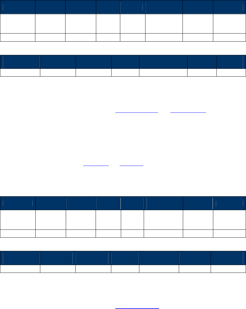
NEO Interface Developers Guide
264
o Enhanced Pass-Through Control
The first command would be formatted as follows:
Byte 0-9 Byte 10 Byte 11 Byte 12
Byte 13
Byte 14 …
Byte 14+n-1
Byte 14+n
Byte 15+n
Header Tag
& Protocol
Version
Command
Sub-
Command
Data
Length
(MSB)
Data
Length
(LSB)
Data CRC
(LSB)
CRC
(MSB)
ViVOtech2\0
2Ch
0Bh
00h
07h
See Below
Byte 0
Single Shot
Byte 1
LCD Index
Byte 2
Beep
Byte 3
LED #
Byte 4
LED Status
Byte 5
Timeout1
Byte 6
Timeout2
05
01
00
00
01
01
01
In this first call of the Enhanced Pass-Through command:
Byte 0 instructs the reader to single-shot the Turn Antenna On and Poll for Token commands
Byte 1 instructs the reader to display message #1 on the display
Byte 2 says that no buzzer is expected
Byte 3 & 4 set the left-most LED on
Byte 5 & 6 set the timeouts (see Timeout1 and Timeout2)
The second command would be formatted as follows:
Byte 0-9 Byte 10 Byte 11 Byte 12
Byte
13
Byte 14 …
Byte 14+n-1 Byte 14+n
Byte 15+n
Header Tag
& Protocol
Version
Command
Sub-
Command
Data
Length
(MSB)
Data
Length
(LSB)
Data CRC
(LSB)
CRC
(MSB)
ViVOtech2\0
2Ch
0Bh
00h
07h
See Below
Byte 0
Single Shot
Byte 1
LCD Index
Byte 2
Beep
Byte 3
LED #
Byte 4
LED Status
Byte 5
Timeout1
Byte 6
Timeout2
02
04
01
FF
02
01
01
In this call of the Enhanced Pass-Through command:
Byte 0 instructs the reader to single-shot the Turn Antenna Off command
Byte 1 instructs the reader to display message #4 (Thank You) on the display

NEO Interface Developers Guide
265
Byte 2 says that give one short beep with the buzzer
Bytes 3 & 4 set all 4 LEDs to blink on then off
Bytes 5 & 6 set the timeouts (see Timeout1 and Timeout2)
Exchange APDU Data (2C-13)
Note: SAM interface is only supported in SRED devices. It is not supported in non-SRED
version.
This command allows exchange of application level APDU’s with the following:
o PICC (contactless card) that is ISO 14443-4 compliant
o SAMs
An application level Command APDU meant for a card or SAM is sent to the reader in the
Command Frame, along with the interface. The reader sends the APDU to the card/SAM. The
response APDU received from the card/SAM is sent back by the reader in the Response Frame.
Before this pass-through command can be used, a Level 1 session must have been established
with a card on the interface to be used i.e., contactless (PICC) or contact (SAM1/SAM2) through
the Enhanced Pass-through command (Poll for Token single shot command).
Command Frame
Byte 0-9
Byte 10
Byte 11
Byte 12
Byte 13
Byte 14
Byte 15
Byte 16
Header Tag
& Protocol
Version
Command
Sub-
Command
Data
Length
(MSB)
Data
Length
(LSB)
Data CRC (LSB)
CRC
(MSB)
ViVOtech2\0
2Ch 13h Variable
See
Command
Data Table
Command Data
Data Item Length (bytes) Description/Example
Interface 1
Allowed interfaces for which to get the ATR.
00h = Contactless
20h = RFU
21h = SAM 1 (SRED version only)
22h = SAM 2 (SRED version only)
Command APDU Variable
Command APDU data that will be sent to the card via the
specified interface. For SAMs, any command/response pair
can be passed.
Response Frame
Byte 0-9 Byte 10 Byte 11 Byte 12
Byte 13
Byte 14 …
Byte 14+n-1
Byte 14+n
Byte 15+n
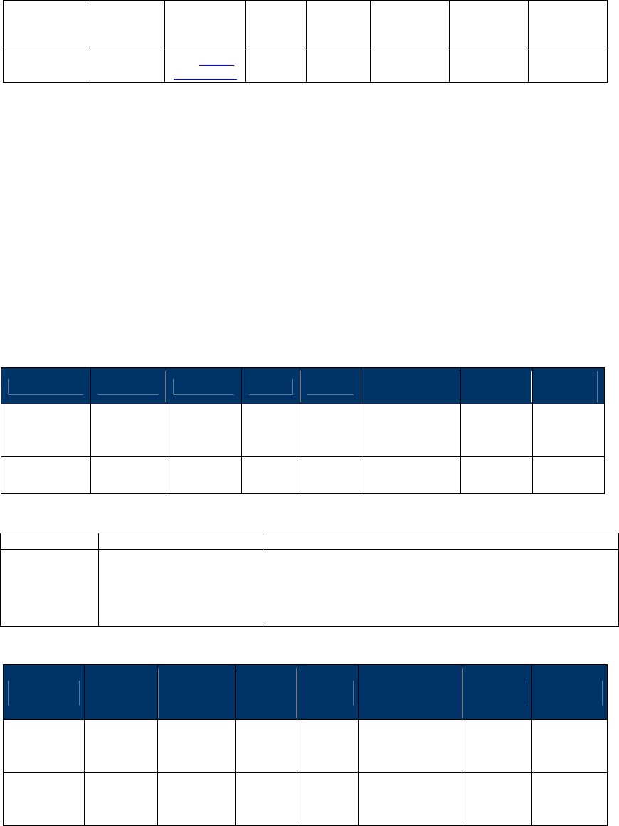
NEO Interface Developers Guide
266
Header Tag
& Protocol
Version
Command
Status Code
Data
Length
(MSB)
Data
Length
(LSB)
Data
CRC (MSB)
CRC (LSB)
ViVOtech2\0
2Ch
See Status
Code Table
00h variable
Response
APDU
For SRED device, if the interface is Contactless, the APDU data being received from the
card/device by the reader will be checked for sensitive data elements using rule in “Secure
Pass-Through Function”. If found, and it has not been established that this transaction belongs
to an AID or BIN on the White List, the Command will return a Parameter Not Supported error
(0x06).
Contact Card Power Off (2C-18)
This command can close contact card power. When transaction is success, the card needs power
off before remove card.
Command Frame
Byte 0-9 Byte 10 Byte 11 Byte 12
Byte 13
Byte 14 …
Byte 14+n-1
Byte
14+n
Byte
15+n
Header Tag
& Protocol
Version
Command
Sub-
Command
Data
Length
(MSB)
Data
Length
(LSB)
Data CRC
(LSB)
CRC
(MSB)
ViVOtech2\0
2Ch 18h Command
Data
Command Data
Data Item Length (bytes) Description/Example
Interface 1 20h = ICC (VP4880C not supported)
21h = SAM 1
22h = SAM 2
Response Frame
Byte 0-9 Byte 10 Byte 11 Byte 12
Byte 13
Byte 14 …
Byte 14+n-1 Byte 14+n
Byte 15+n
Header Tag
& Protocol
Version
Command
Status Code
Data
Length
(MSB)
Data
Length
(LSB)
Data CRC
(MSB)
CRC
(LSB)
ViVOtech2\
0 2Ch
See
Status
Code
Table
00h 00h
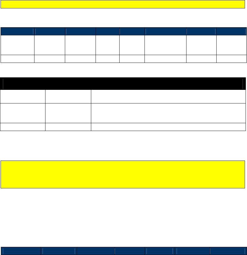
NEO Interface Developers Guide
267
High Level Pass-Through Commands for Mifare Cards
This section contains serial commands that implement higher level functionality for the Mifare
Cards. These commands can only be used once the reader has been put in Pass-Through mode
and the “Poll for Token” command has indicated that a Mifare Card is present. These commands
do not work for non-Mifare cards.
Mifare Authenticate Block (2C-06)
This command allows the terminal to instruct the ViVOpay reader to authenticate the Mifare
Card sector containing the specified block of data. The Key to be used is also specified by the
terminal. This command is applicable only for Mifare Standard/Classic Cards.
This command is not applicable for Mifare Ultralight Cards.
Command Frame
Byte 0-9
Byte 10
Byte 11
Byte 12
Byte 13
Byte 14–Byte 21
Byte 22
Byte 23
Header Tag &
Protocol
Version
Command
Sub-
Command
Data
Length
(MSB)
Data
Length
(LSB)
Data CRC (MSB)
CRC (LSB)
ViVOtech2\0
2Ch
06h
00h
08h
See Table below
Table 71: Mifare Authentication Block Data Field
Data Field Length (bytes) Description
Block
1
Block Number in the Mifare Card for which the relevant sector
must be authenticated.
Key Type
1
Specifies which type of key to use for authentication. It can
have the following values.
01h: Key A 02h: Key B
Key
6
Value of the Key
For details on these fields, refer to the relevant Mifare Specifications
This command does not actually perform the authentication. It sets the key to be used for
the subsequent authentication. The actual authentication will be performed before the next
read or write operation. If a sector boundary is crossed, the reader will attempt to
authenticate using the key that was established with this command.
After receiving the Command Frame, the ViVOpay reader verifies the data and if the data is
valid, it interacts with the Mifare card to authenticate the sector containing the specified block.
If this operation is successful, the ViVOpay reader sends a Response Frame with an OK Status. If
the operation fails or the data was invalid, then the reader returns a Response Frame with an
appropriate Status.
Response Frame
Byte 0-9
Byte 10
Byte 11
Byte 12
Byte 13
Byte 14
Byte 15

NEO Interface Developers Guide
268
Header Tag &
Protocol
Version
Command Status Code
Data
Length
(MSB)
Data
Length
(LSB)
CRC (MSB) CRC (LSB)
ViVOtech2\0 2Ch
See Status
Code Table
00h 00h
If the card in the field is not a Mifare card, a 0Ch (Sub-command not allowed) will be returned
in the status code.
Mifare Read Blocks (2C-07)
Use this command to read data from one or more blocks on the Mifare Card. The terminal can
instruct the reader to read up to 15 blocks using this command. If more than one block is
defined, then the reader automatically reads the starting block and the blocks that follow. For
multi-block reads, the sector trailer will be skipped. Sector trailer’s may be read (except that
the keys will not be visible) using a single block read.
If the card specified is a Mifare Standard card, then the terminal must have successfully sent at
least one Mifare Authenticate Block command to the reader for the first block to read. This
does not authenticate the block; it stores a key for use by the reader as it performs reads and
writes.
If the card specified is a Mifare Standard card and the read command specifies a single block
read, then the reader tries to read the data regardless of whether the block is a sector
trailer block.
If the card specified is a Mifare Standard card, and the read is a multi-block read, then the
reader skips reading the sector trailer blocks that contain the Keys (since the Keys cannot be
read). Skipped blocks are not included in the block count. While reading blocks in a Mifare
Standard Card, if the read requires access to the next sector, then the ViVOpay reader carries
out authentication for this block/sector automatically by using the Key Type and Key Value that
were set in the Mifare Authenticate Block command to authenticate the sector for the Starting
Block via the Mifare Authenticate Block command.
Block reads and writes that span multiple sectors assume that the keys to authenticate those
sectors are the same as the one that was set using the Mifare Authenticate Block command.
Command Frame
Byte 0-9
Byte 10
Byte 11
Byte 12
Byte 13
Byte 14,15
Byte 16
Byte 17
Header Tag &
Protocol
Version
Command
Sub-
Command
Data
Length
(MSB)
Data
Length
(LSB)
Data CRC (MSB)
CRC (LSB)
ViVOtech2\0
2Ch
07h
00h
02h
See Table below
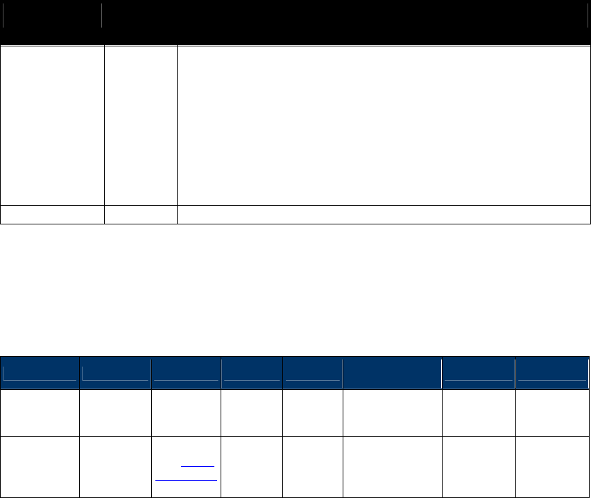
NEO Interface Developers Guide
269
Table 72: Mifare Read Block Data Field
Data Field Length
(bytes)
Description
Card & Block
Count
1
Card Type: [Bit 7..4]
This can only indicate the following cards
Mifare Type A (Standard)
Mifare Type A (Ultralight)
The values for these card types are defined in the “Poll for Token”
command (consider only the lower 4 bits).
Block Count: [Bit 3..0]
This is the number of 16-byte blocks that are read.
The Block Count cannot be greater than 15.
This count does not include the skipped blocks if the card is a Mifare
Standard card.
Start Block
1
This is the card block number from which the reader starts reading.
After receiving the Command Frame the ViVOpay reader verifies the parameters. If the
parameters are valid, then it reads the data from the card. If this operation is successful, the
ViVOpay reader sends a Response Frame containing a Status of OK and the data that was read. If
the operation fails or one or more parameters were invalid, then the reader sends a Response
Frame containing an appropriate Status, but no data.
Response Frame
Byte 0-9 Byte 10 Byte 11 Byte 12
Byte 13
Byte 14 …
Byte 14+n-1
Byte 14+n
Byte 15+n
Header Tag
& Protocol
Version
Command
Status
Code
Data
Length
(MSB)
Data
Length
(LSB)
Data CRC (MSB)
CRC (LSB)
ViVOtech2\0
2Ch See Status
Code Table
Variable
Variable
Data Read from
Card
OR
None
If the Status is OK, then the Data Length depends on the number of blocks read and the card
type.
DataLen = Blocks Read * (Bytes per Block for Card).
If there was an error or no data was read, then the Data Length is zero.
For SRED device, the data being received from the card/device by the reader will be checked
for sensitive data elements using rule in “Secure Pass-Through Function”. If found, and it has
not been established that this transaction belongs to an AID or BIN on the White List, the
Command will return a Parameter Not Supported error (0x06).
9.1.1.12 Reading Mifare Ultralight Cards
Mifare Ultralight cards differ from Mifare Cards. For Mifare Standard Cards the block size is 16
bytes. However, for Mifare Ultralight Cards the block (page) size is 4 bytes. When reading
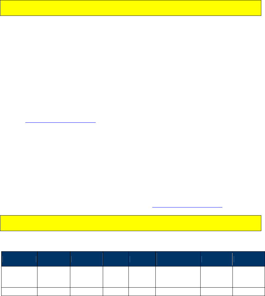
NEO Interface Developers Guide
270
Mifare Ultralight cards, Block Count is taken to mean the number of 16 byte blocks (each
consisting of four 4-byte pages). However, for Mifare Ultralight cards, the Start Block
represents a 4-byte page.
For example, if the card is a Mifare Ultralight card, and a read is requested starting at Block 3
and Block Count is 1 then 16 bytes of data are returned consisting of Page # 3, 4, 5 & 6. And if a
read is requested starting at Block 3 and Block Count is 2 then 16*2=32 bytes of data are
returned consisting of Page # 3, 4, 5, 6, 7, 8, 9, and 10.
Typically, Mifare Ultralight Cards are read by the ViVOpay reader, but are not written. This
is because they are typically used for disposable applications such as ticketing.
Mifare Write Blocks (2C-08)
Use this command to instruct the ViVOpay reader to write data to one or more blocks on the
Mifare Card. The terminal can instruct ViVOpay to write up to 15 blocks of data using this
command. If more than one block is defined, then the reader automatically writes to the
starting block and the blocks that follow.
The block size depends on the type of Mifare card being accessed. For Mifare Standard Cards the
block size is 16 bytes. For Mifare Ultralight Cards the block size is 4 bytes.
If the card specified is a Mifare Standard card, then the terminal must have successfully sent at
least one Mifare Authenticate Block command to the reader for the first block to write. This
does not authenticate the block; it stores a key for use by the reader as it performs reads and
writes.
If the card specified is a Mifare Standard card and the write command is a single block write,
the reader tries to write the data regardless of whether the block is a sector trailer block or not.
If the card specified is a Mifare Standard card, and the write is a multi-block write, then the
reader skips writing to the sector trailer blocks that contain the Keys. Skipped blocks are not
included in the block count. While writing blocks to a Mifare Standard Card, if the write requires
access to the next sector, then the ViVOpay reader carries out authentication for this
block/sector automatically by using the Key Type and Key Value that were used by the terminal
to authenticate the sector for the Starting Block via the Mifare Authenticate Block command.
Block reads and writes that span multiple sectors assume that the keys to authenticate those
sectors are the same as the one that was set using the Mifare Authenticate Block command.
Command Frame
Byte 0-9 Byte 10 Byte 11 Byte 12
Byte 13
Byte 14 … Byte
14+n-1
Byte 14+n
Byte 15+n
Header Tag &
Protocol
Version
Command
Sub-
Command
Data
Length
(MSB)
Data
Length
(LSB)
Data CRC
(MSB) CRC (LSB)
ViVOtech2\0
2Ch
08h
Variable
Variable
See Table below

NEO Interface Developers Guide
271
Table 73: Mifare Write Block Data Field
Data Field Length
(bytes)
Description
Card & Block Count
1
Card Type: [Bit 7..4]
This can only indicate the following cards
Mifare Type A (Standard)
Mifare Type A (Ultralight)
The values for these card types are defined in the “Poll for Token”
command (consider only the lower 4 bits).
Block Count: [Bit 3..0]
This is the number of blocks that are written. The Block Count cannot be
greater than 15. This count does not include the skipped blocks if the
card is a Mifare Standard card.
Start Block
1
This is the card block number from which the reader starts writing.
Data to Write
Variable
(multiple
of block
size)
Data to write to the Card.
The length of the data to be written to the card depends on the number
of blocks to be written and the card type.
After receiving the Command Frame the ViVOpay reader verifies the parameters. If the
parameters are valid, it writes the data to the card. If this operation is successful, the ViVOpay
reader sends a Response Frame with a Status of OK.
If the Command Frame is invalid or the write operation fails then the reader sends a Response
Frame with an appropriate Status.
Response Frame
Byte 0-9
Byte 10
Byte 11
Byte 12
Byte 13
Byte 14
Byte 15
Header Tag &
Protocol Version
Command
Status Code
Data Length
(MSB)
Data Length
(LSB)
CRC (MSB)
CRC (LSB)
ViVOtech2\0 2Ch
See Status
Code Table
00h 00h
Mifare ePurse Command (2C-0A)
Use this command to instruct the ViVOpay reader to carry out Debit, Credit and Backup
operations on value blocks in a Mifare card. These functions require that the related data blocks
be formatted as a value block and that operations and keys used match the defined Access
Conditions for that sector.
The following illustration shows the format of a value block:
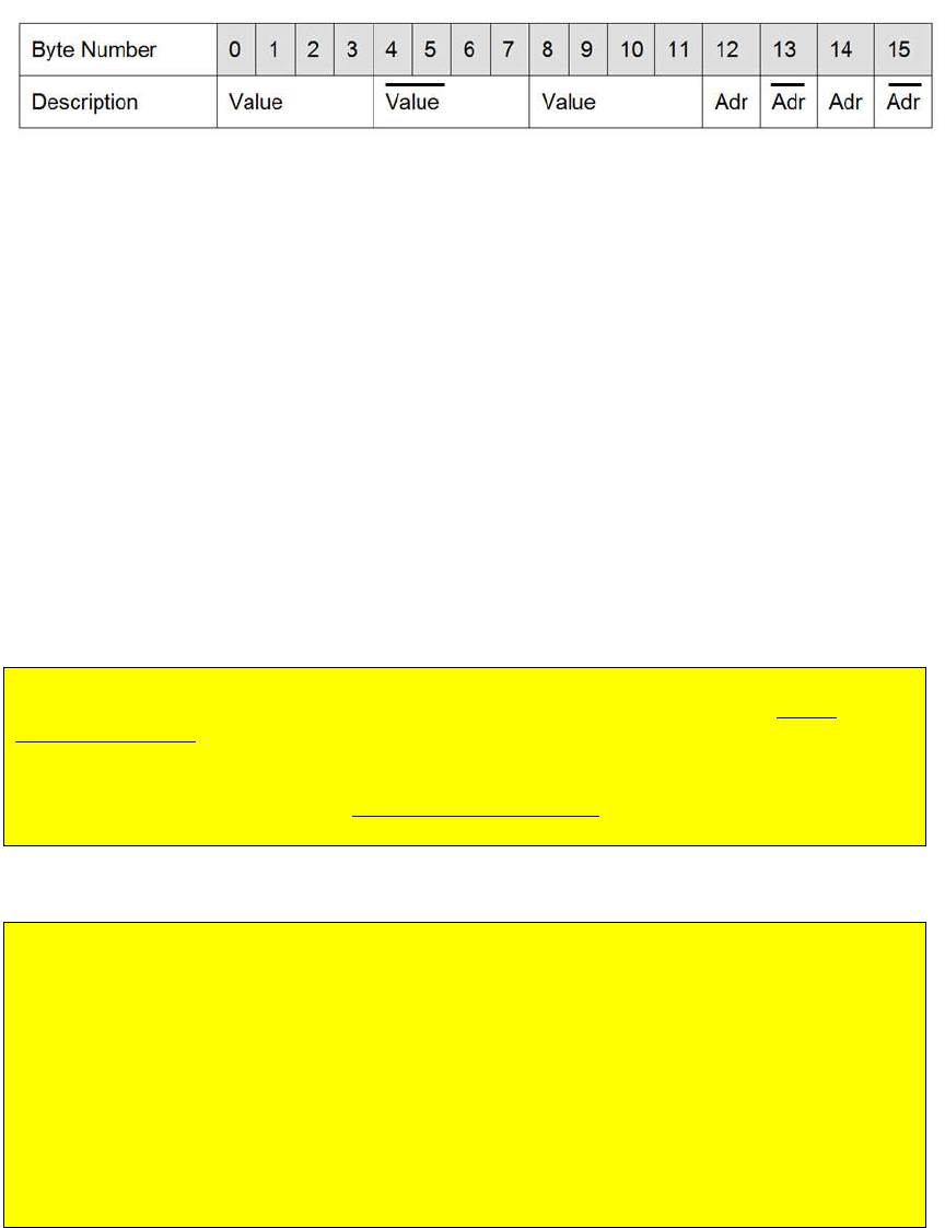
NEO Interface Developers Guide
272
Table 74: ePurse Value Block Format
A Debit function subtracts a given amount from a Mifare value block and stores the result in the
same block. A Credit function adds a given amount to a Mifare value block and stores the result
in the same block. A Backup function reads a value block and stores a copy of it in another value
block in the same authenticated sector.
This command is flexible in that it allows any number of Debit, Credit or Backup function blocks
to be embedded within one Command Frame in any order, with or without keys specified, as
long as the total number of bytes is within the size capability of one Pass-Through command.
Operations are performed in the order they are specified.
For instance, a Purse Command could simply contain one Debit function to debit a value block
by a specified amount. If a key and key type is included they are used to authenticate the block
and the debit function is performed. If no key information is included the key and key type used
in the previous Mifare Authentication command is used.
In another case, the Purse Command could contain a Credit function to credit a value block by a
specific amount and a Backup function to backup the resulting balance to another value block
somewhere on the card. Each command could include a specific key for the block being
addressed, or omit the key information and let the reader use the last known key.
Note: The default key and key type are overwritten each time a key is encountered while
processing a Purse Command. The initial default values are those set when the Mifare
Authenticate Block command is received. That key type and key are used until another key is
encountered, at which point the new key becomes the default key for subsequent
transactions. If purse commands are used without key information then the terminal must
have successfully sent at least one Mifare Authenticate Block command to the reader for the
first block.
Warning: Multiple ePurse command blocks can be included in one command; each command
contains a count of the number of command blocks included in the command.
If the count of command blocks specified is not equal to the actual number of command
blocks included in the command, an error may or may not be returned to the user.
If the count of command blocks is greater than the actual number of command blocks
specified, all command blocks available are acted upon and an error is returned.
If the count of command blocks is less than the actual number of command blocks in the
command, only the number of commands specified in the count is acted upon but no error is
returned.
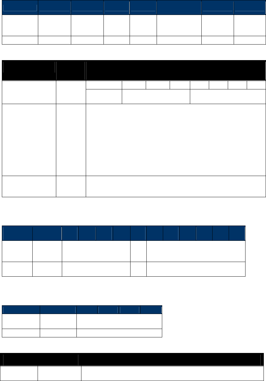
NEO Interface Developers Guide
273
Command Frame
Byte 0-9 Byte 10 Byte 11 Byte 12
Byte 13
Byte 14 … Byte
14+n-1
Byte 14+n
Byte 15+n
Header Tag &
Protocol
Version
Command
Sub-
Command
Data
Length
(MSB)
Data
Length
(LSB)
Data CRC (MSB)
CRC (LSB)
ViVOtech2\0
2Ch
0Ah
Variable
Variable
See Table below
Table 75: Mifare ePurse Command Data Field
Data Field Length
(bytes)
Description
Mode, Card Type &
Operation Count
1
7
6
5
4
3
2
1
0
1 = Inc
0 = Dec Card Type Operation Count
Increment / Decrement Flag: [Bit 7]
Set to 1 instructs reader to Add to (Credit) amount.
Set to 0 instructs reader to Subtract from (Debit) amount.
Card Type: [Bit 6..4]
This can only indicate Mifare Type A (Standard) card (3, as defined in
the “Poll for Token” command).
Operation Count: [Bit 3..0]
This is the number of operation command blocks contained within the
rest of the Purse Function data area.
Purse Function
Blocks
Variable
[1]
Series of any combination of supported Purse Function blocks
(Debit/Credit, Backup). Refer to the description of each individual
Command Frame below.
Debit / Credit Function Block (with Key specified)
Byte
0
Byte
1
Byte
2
Byte
3
Byte
4
Byte
5
Byte
6
Byte
7
Byte
8
Byte
9
Byte
10
Byte
11
Byte
12
Value
Block
Number
Command
Length Amount Key
Type
Key
0Bh See Table below
See
Table
See Table
Debit / Credit Function Block (using default Key)
Byte 0
Byte 1
Byte 2
Byte 3
Byte 4
Byte 5
Value Block
Number
Command
Length
Amount
04h
See Table
Table 76: Mifare ePurse Data Field for Debit/Credit Function Block
Data Field Length (bytes)
Description
Amount
4
Amount to be added (Debit) or subtracted (Credit) in Little-Endian
format. Mode of operation (+ or - ) is specified by most significant bit
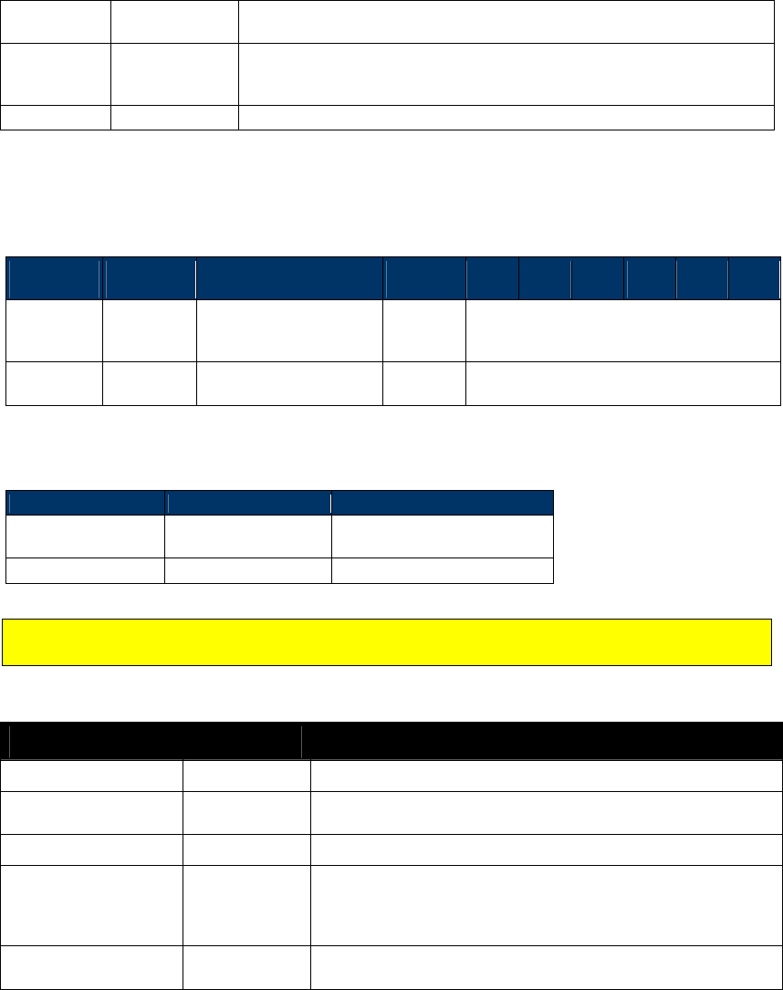
NEO Interface Developers Guide
274
of first data byte in Purse Command (Mode, Card Type and Operation
Count)
Key Type
1
Specifies which type of key to use for authentication. It can have the
following values.
01h: Key A 02h: Key B
Key
6
Value of the Key
For details on these fields, refer to the relevant Mifare Specifications.
Backup Function Block (with Key specified)
Byte
0
Byte
1
Byte
2
Byte
3
Byte
4
Byte
5
Byte
6
Byte
7
Byte
8
Byte
9
Backup
Block
Number
Command
Length
Primary
Block
Number
Key Type
Key
See Table
below 08h See Table below
See Table
below
See Table below
Backup Function Block (using default Key)
Byte 0
Byte 1
Byte 2
Backup Block
Number
Command Length
Primary Block
Number
See Table below
01h
See Table below
Mifare ePurse backup commands are distinguished from Debit/Credit operations by the value
in the Command Length field.
Table 77: Mifare ePurse Data Field for Backup Function Block
Data Field Length (bytes)
Description
Backup Block Number
1
Number of destination value block to be used for backup.
Command Length
1
Set to 01h or 08h, depending on whether a key type and key
are supplied.
Primary Block Number
1
Number of source value block to be copied.
Key Type
1
Present only if Command Length = 08h
Specifies which type of key to use for authentication. It can
have the following values.
01h: Key A 02h: Key B
Key
6
Present only if Command Length = 08h
Value of the Key
For details on these fields, refer to the relevant Mifare Specifications.
After receiving the Command Frame the ViVOpay reader verifies the parameters. If the
parameters are valid, it performs the operations specified in the order in which they appear
within the Purse Command Data Frame.
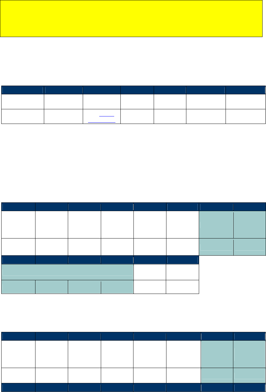
NEO Interface Developers Guide
275
Note: Although it is possible to include multiple value operations (Debit or Credit) in one
command, because there is only a single one-bit flag to specify the Debit or Credit mode all
value commands within one Purse Command must be either Debit or Credit functions.
(However, backup operations may be included because they are distinguished by the
command length field).
If all operations are successful, the ViVOpay reader sends a Response Frame with a Status of OK.
If the Command Frame is invalid or any of the operations fail then the reader sends a Response
Frame with an appropriate Status.
Response Frame
Byte 0-9
Byte 10
Byte 11
Byte 12
Byte 13
Byte 14
Byte 15
Header Tag &
Protocol Version
Command Status Code
Data Length
(MSB)
Data Length
(LSB)
CRC (MSB) CRC (LSB)
ViVOtech2\0 2Ch
See Status
Code Table
00h 00h
Examples
Application: Perform a Debit operation. Subtract 2000 from value block number 20H using last
key specified. Blue shaded area shows the Debit function block within the Purse Command
Frame.
Command Frame
Byte 0-9
Byte 10
Byte 11
Byte 12
Byte 13
Byte 14
Byte 15
Byte 16
Header Tag
& Protocol
Version
Command
Sub-
Command
Data Length
(MSB)
Data Length
(LSB)
Mode,
Card Type,
Operation
Count
Value Block
Debit Cmd
Length
ViVOtech2\0
2Ch 0Ah 00h 07h 31h 20h 04h
Byte 17
Byte 18
Byte 19
Byte 20
Byte 21
Byte 22
Debit Amount CRC MSB CRC LSB
D0h 07h 00h 00h
Application: Perform a Credit operation. Add 100 to value block number 20H specifying Key A.
Blue shaded area shows the Credit function block within the Purse Command Frame.
Command Frame
Byte 0-9
Byte 10
Byte 11
Byte 12
Byte 13
Byte 14
Byte 15
Byte 16
Header Tag
& Protocol
Version
Command
Sub-
Command
Data Length
(MSB)
Data Length
(LSB)
Mode,
Card Type,
Operation
Count
Value Block
Credit Cmd
Length
ViVOtech2\0
2Ch 0Ah 00h 0Eh B1h 20h 0Bh
Byte 17
Byte 18
Byte 19
Byte 20
Byte 21
Byte 22
Byte 23
Byte 24
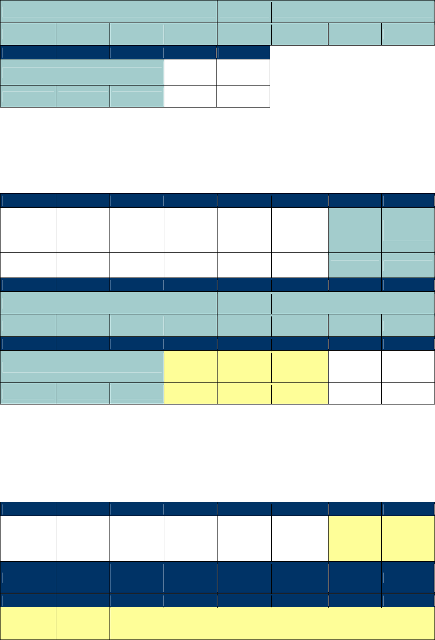
NEO Interface Developers Guide
276
Credit Amount Key Type
Key
64 00 00 00 01 Ka Kb Kc
Byte 25
Byte 26
Byte 27
Byte 28
Byte 29
Key CRC MSB CRC LSB
Kd Ke Kf
Application: Perform a Debit operation with Backup. Subtract 300 from value block number 20H
specifying Key A and backup the result to value block number 21H using the same key. Blue
shaded area shows the Debit function block and yellow shaded area shows the Backup function
block within the Purse Command Frame.
Command Frame
Byte 0-9
Byte 10
Byte 11
Byte 12
Byte 13
Byte 14
Byte 15
Byte 16
Header Tag
& Protocol
Version
Command
Sub-
Command
Data Length
(MSB)
Data Length
(LSB)
Mode,
Card Type,
Operation
Count
Value Block
Debit Cmd
Length
ViVOtech2\0
2Ch 0Ah 00h 11h 32h 20h 0Bh
Byte 17
Byte 18
Byte 19
Byte 20
Byte 21
Byte 22
Byte 23
Byte 24
Debit Amount Key Type
Key
2Ch 01 00 00 01 Ka Kb Kc
Byte 25
Byte 26
Byte 27
Byte 28
Byte 29
Byte 30
Byte 31
Byte 32
Key Backup
Block
Backup Cmd
Length
Primary
Block CRC MSB CRC LSB
Kd Ke Kf 21h 01h 20h
Application: Perform a Backup (value copy) operation only. Copy the value amount from block
1CH to block 1DH specifying Key B. Yellow shaded area shows the Backup function block within
the Purse Command Frame.
Command Frame
Byte 0-9
Byte 10
Byte 11
Byte 12
Byte 13
Byte 14
Byte 15
Byte 16
Header Tag
& Protocol
Version
Command
Sub-
Command
Data Length
(MSB)
Data Length
(LSB)
Mode,
Card Type,
Operation
Count
Backup
Block
Backup
Cmd Length
ViVOtech2\0
2Ch 0Ah 00h 0Bh 31h 1Dh 08h
Byte 17
Byte 18
Byte 19
Byte 20
Byte 21
Byte 22
Byte 23
Byte 24
Primary
Block Key Type
Key
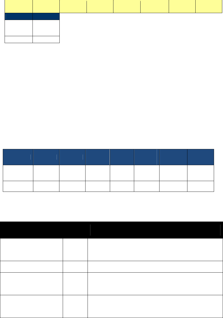
NEO Interface Developers Guide
277
1Ch 02h Ka Kb Kc Kd Ke Kf
Byte 25
Byte 26
CRC MSB CRC LSB
High Level Pass-Through Commands for NFC Cards
This section contains serial commands that implement higher level functionality for the NFC
Cards. These commands do not work for non-NFC cards.
NFC Commands (2C-40)
This command uses Data[0] in command data field to implement different functions. This
command should be used in Pass-Through mode and command with “Poll for a NFC Tag” data
should be used first. Command with other data can only be used once the “Poll for a NFC Tag”
command has indicated that a NFC tag is present.
NFC Commands
Byte 0-9 Byte 10 Byte 11 Byte 12 Byte 13
Byte
14 ...Byte
13+n
Byte 14+n
Byte 15+n
Header Tag
& Protocol
Version
Command
Sub-
Command
Data
length
(MSB)
Data
length
(LSB)
Data CRC(MSB)
CRC(LSB)
ViVOtech2\0
2Ch 40 00 00
See
Below
Individial commands in NFC command set are distingushed as to parameters in Data field.
Table 78: NFC Command Set List
Command Data
length Command Data Field Description
Poll for a NFC Tag 2
Data[0]: FFh
Data[1]: Timeout (in second)
Tag1 Static Get All Data 1 Data[0]: 11h
Tag1 Static Read a Byte 2
Data[0]: 12h
Data[1]: Address of the data
Tag1 Static Write a Byte 3
Data[0]: 13h
Data[1]: Address of the data

NEO Interface Developers Guide
278
Data[2]: Data to be written
Tag1 Static Write a Byte NE
3
Data[0]: 14h
Data[1]: Address of the data
Data[2]: Data to be written
Tag1 Dynamic Read a
Segment 2
Data[0]: 15h
Data[1]: Address of the segment
Tag1 Dynamic Read 8 Bytes 2
Data[0]: 16h
Data[1]: Address of the data
Tag1 Dynamic Write 8 Bytes
10
Data[0]: 17h
Data[1]: Address of the data
Data[2]~Data[9]: Data to be written
Tag1 Dynamic Write 8 Bytes
NE 10
Data[0]: 18h
Data[1]: Address of the data
Data[2]~Data[9]: Data to be written
Tag2 Read Data (16 bytes) 2
Data[0]: 21h
Data[1]: Address of the data
Tag2 Write Data (4 bytes) 6
Data[0]: 22h
Data[1]: Address of the data
Data[2]~Data[5]: Data to be written
Tag2 Select Sect 2
Data[0]: 23h
Data[1]: Sect number
Tag3 Read Data variable
Data[0]: 41h
Data[1]: Number of services, value n.
Data[2]~Data[2n+1]: Service code list
Data[2n+2]: Number of blocks, value m.
Data[2n+3....]: Block list, length is 2m~3m
Tag3 Write Data variable
Data[0]: 42h
Data[1]: Number of services, value n.
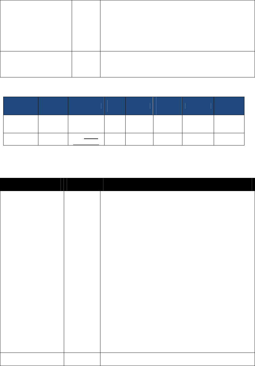
NEO Interface Developers Guide
279
Data[2]~Data[2n+1]: Service code list
Data[2n+2]: Number of blocks, value m.
Data[2n+3....]: Block list, length is 2m~3m
Data[...]: Block data, length is 16m
Tag4 Command variable
Data[0]: 0x81
Data[1]~Data[n]: data
NFC Response
Byte 0-9 Byte 10 Byte 11 Byte
12 Byte 13
Byte
14 ...Byte
13+n
Byte 14+n
Byte 15+n
Header Tag
& Protocol
Version
Command
Status
Data
length
(MSB)
Data
length
(LSB)
Data CRC(MSB)
CRC(LSB)
ViVOtech2\0
2Ch
See Status
Code Table
00 00
See
Below
Table 79: NFC Command Set Response Data List
Command Response Data length Command Response Data Field Description
Poll for a NFC Tag variable Data[0]: Card type
00h None (Card Not Detected or Could not Active)
01h ISO 14443 Type A (Supports ISO 14443-4 Protocol)
02h ISO 14443 Type B (Supports ISO 14443-4 Protocol)
03h Mifare Type A (Standard)
04h Mifare Type A (Ultralight)
05h ISO 14443 Type A (Does not support ISO 14443-4
Protocol)
06h ISO 14443 Type B (Does not support ISO 14443-4
Protocol)
07h ISO 14443 Type A and Mifare (NFC phone)
0Ah NFC Tag 1
0Bh NFC Tag 2
0Ch NFC Tag 3
0Dh NFC Tag 4
Data[1...]: Serial Number (or the UID) of the PICC. Length
depends on the card detected. If no card was detected, then a
Serial Number is not returned.
Others variable Returned data from card

NEO Interface Developers Guide
280
For details on these data field, refer to the relevant NFC Specifications.
For SRED device, if the command isn’t “Poll for a NFC Tag”, the data being received from the
card/device by the reader will be checked for sensitive data elements using rule in “Secure
Pass-Through Function”. If found, and it has not been established that this transaction belongs
to an AID or BIN on the White List, the Command will return a Parameter Not Supported error
(0x06).
Secure Pass-Through Function
Note: In SRED device, Pass-Through mode is called Secure Pass-Through Mode.
(1) General Introduction
In Secure Pass-Thru mode the reader will not allow the exposure of sensitive financial data
from the reader unless the data from the card provides an Application Identifier (AID) or a Bank
Identification Number (BIN) that is listed in the White List. An AID or BIN added to the White List
is a guarantee that the AID or BIN is not used for a financial transaction.
In Secure Pass-Thru mode, if the AID or BIN is not in the White List, then all data returned
from the card is parsed and analyzed to detect sensitive financial data before that data is
provided in the transaction response. If any sensitive financial data is found only an error is
returned and no data from the card is provided for the entire transaction.
Note: In Secure Pass-Through Function, use the entire PAN as input BIN to compare with the
BIN in White List
(2) Secure Pass-Thru White List
The White List is loaded with MAC verification. The White List is a list of AID’s and BIN’s that
will be used to determine if data that appears to be financial data will be allowed and shown in
clear text.
If an AID selected is on the Secure Pass-Thru White List, all data for that transaction will be
shown in clear text regardless of whether it is sensitive financial data or not. The Selected AID is
not dependent on the occurrence of PPSE or List of AID’s selection methods. If the AID selected
is not on the Secure Pass-Thru White List, all data received from PICC will be parsed searching
for sensitive financial data. Any TLV or structure on the SRED list of protected financial data will
cause the Pass-Thru command response to return a Parameter Not Supported error status (0x06)
with no data.
If a BIN is found in a track data TLV or track data structure, that is also in the White List, all
data for that transaction will be shown in clear text regardless of whether it is sensitive
financial data or not. If the BIN is not on the White List the Pass-Thru command response will
return a Parameter Not Supported error status (0x06) with no data. Since the BIN is embedded
in track data, the fact that there was a BIN indicates sensitive data was found.

NEO Interface Developers Guide
281
Note: In either the matching AID or matching BIN scenarios, if sensitive data is retrieved in a
command prior to the command where the AID or BIN that matches the White List is found, the
transaction response will return a Parameter Not Supported status (0x06) error with no data.
WARNING – No Card Association AID’s may be added to the white list. For example the AID’s
for Mastercard, Visa, Amex, etc. may NOT be added to the White List.
(1) Handling Sensitive Financial Data
Any TLV or structure on the SRED list of protected financial data will cause the Pass-Thru
command response to return a Parameter Not Supported status (0x06) with no data returned.
SRED List of Protected Financial Data
TLV
Name
Find Method
56
Track 1 Equivalent Data
Match EMV TLV
57
Track 2 Equivalent Data
Match EMV TLV
5A
Application PAN
Match EMV TLV
5F20
Cardholder Name
Match EMV TLV
5F24
Application Expiration Date
Match EMV TLV
5F30
Service Code
Match EMV TLV
9F27
Cryptogram Information
Data
Match EMV TLV
9F60
CVC3Track1
Match EMV TLV
9F61
CVC3Track2
Match EMV TLV
9F6B
Track 2 Data
Match EMV TLV
none
Track 1
Matches ISO/IEC 7813 format for Track 1. See
details in Track 1 Format Test below.
none
Track 2
Matches ISO/IEC 7813 format for Track 2. See
details in Track 2 Format Test below.
none
Track 3
Matches ISO/IEC 4909:2006 format for Track 3. See
details in Track 3 Format Test below.
(2) Accessing SAMs in Pass- Thru Mode
In Secure Pass-Thru SAM access is always clear data. The SAM will never contain sensitive
financial data.
(3) Pass-Thru Command Need to be parsed for sensitive financial data
Cmd-Sub
Name
2C-03
Exchange APDU
2C-04
PCD Single Command Exchange
2C-07
Read Mifare Block
2C-13
Exchange APDU
2C-40
NFC Commands
(4) Secure Pass-Thru White List
WARNING – No Card Association AID’s may be added to the white list. For example the AID’s
for Mastercard, Visa, Amex, etc. may NOT be added to the White List.

NEO Interface Developers Guide
282
White List related commands can only be used when Pass-Through mode is started.
Set White List (2C-50)
This command allows saving the new “White List” in the reader. The list is authenticated by
appending a keyed-hash message authentication code (HMAC-SHA256, RCF-2104) to the message.
The key is called MAC DUKPT Key. This key is loaded into device using ViVOpay Key Management
Architecture with key slot 3.
Command Frame
Byte 0-9 Byte 10 Byte 11 Byte
12
Byte
13 Byte 14,15 Byte 16
Byte 17
Header Tag
& Protocol
Version
Command
Sub-
Command
Data
Length
(MSB)
Data
Length
(LSB)
Data CRC
(LSB)
CRC
(MSB)
ViVOtech2\0
2Ch 50h var var See Tables
Below
Set White List Data Field
Data Field Length
(bytes)
Description
White List
Var up
to 512
The actual white list. See format of White List below.
Tag: FFEE0C Format: Constructed
HMAC 36 32 bytes HMAC-SHA256 of the white list (RFC-2104) using
MAC DUKPT Key. The white list to do MAC verification is the
value of FFEE0C TLV.
Tag: DFEF23 Format: binary
KSN 14 10 bytes current MAC DUKPT Key Sequence Number. Device
uses current MAC DUKPT Key to do MAC verification.
Tag: DFEE12 Format: binary
The White List is composed of the following proprietary TLV’s, some of which may be embedded
with wildcard symbols.
White List Format
Data Field Length
(bytes) Description
BIN
Var up
to 19
A single BIN with possible wildcards.
Tag: DFEF21 Format: ASCII ‘0-9’,’*’,’?’
AID Var up
to 32
A single AID with possible wildcards.
Tag: DFEF22 Format: ASCII ‘A-Z’,‘0-9’,’*’,’?’
BIN Range var Contains two BIN’s (DFEF21). Any BIN including and between the
first BIN and second BIN is considered to be nonfinancial
regardless of content. No wildcards allowed.
Tag: FFEE0A Format: TLVs

NEO Interface Developers Guide
283
Data Field Length
(bytes) Description
AID Range
var
Contains two AID’s (DFEF22). Any AID including and between the
first AID and second AID is considered to be nonfinancial
regardless of content. No wild cards allowed.
Tag: FFEE0B Format: TLVs
Possible Wild Cards
Wildcard
Symbol
Description of wildcard
*
The asterisk in a wildcard matches any character zero or more times. For
example, "1234*" matches anything beginning with "1234" which means "1234",
"12345", and "123456789" are all matched.
?
A question mark matches a single character once. For example, "1?34" matches
"1234" and "1934". The question mark can also be used more than once. For
example, "1??4" would match both of the above examples as well as "1984".
Note:
(1) Wildcards cannot be used in the AID’s or BIN’s used in the Range TLV’s (FFEE0A and FFEE0B).
(2) The white list may contain several single BIN TLVs or several single AID TLVs or several BIN
range TLVs or several AID Range TLVs.
(3) For all BIN Range and AID Range, the fist and second BIN or AID must have the same length,
the first BIN or AID must be less than the second BIN or AID.
Response Frame
Byte 0-9 Byte 10 Byte
11 Byte 12 Byte 13 Byte 14 …
Byte 13+n
Byte
14+n
Byte
15+n
Header Tag
& Protocol
Version
Comman
d
Status
Code
Data
Length
(MSB)
Data
Length
(LSB)
Data CRC
(MSB)
CRC
(LSB)
ViVOtech2\
0 2Ch
See
Status
Codes
00h 00h None
If the White List is authenticated by the HMAC, the White List will be saved and used for
transaction processing. If the White List is not authenticated the status response will be 0x0A
Failed. If the input White List format is error, the status response will be 0x0A Failed.
Get White List (2C-51)
This command retrieves the White List.
Command Frame
Byte 0-9 Byte 10 Byte 11 Byte
12
Byte
13 Byte 14,15 Byte 16
Byte 17
Header Tag
& Protocol
Version
Command
Sub-
Command
Data
Length
(MSB)
Data
Length
(LSB)
Data CRC
(LSB)
CRC
(MSB)

NEO Interface Developers Guide
284
Byte 0-9 Byte 10 Byte 11 Byte
12
Byte
13 Byte 14,15 Byte 16
Byte 17
ViVOtech2\0
2Ch
See
Status
Codes
var var Response
Data
Response Frame
Byte 0-9 Byte 10 Byte
11 Byte 12 Byte 13 Byte 14 …
Byte 13+n
Byte
14+n
Byte
15+n
Header Tag
& Protocol
Version
Comman
d
Status
Code
Data
Length
(MSB)
Data
Length
(LSB)
Data CRC
(MSB)
CRC
(LSB)
ViVOtech2\
0 2Ch Status
Variable Variable
Response
Data
Response Data - See tables for Set White List above for the White List format and options.
Data Field Length
(bytes)
Description
White List Var The actual white list. See format of White List in Set White
List section above.
Tag: FFEE0C Format: Constructed
Clear White List (2C-52)
This command instructs the reader to clear the white list.
Command Frame
Byte 0-9 Byte 10 Byte 11 Byte
12
Byte
13 Byte 14,15 Byte 16
Byte 17
Header Tag
& Protocol
Version
Command
Sub-
Command
Data
Length
(MSB)
Data
Length
(LSB)
Data CRC
(LSB)
CRC
(MSB)
ViVOtech2\0
2Ch
52h
00h
00h
None
Response Frame
Byte 0-9 Byte 10 Byte
11 Byte 12 Byte 13 Byte 14 …
Byte 13+n
Byte
14+n
Byte
15+n
Header Tag
& Protocol
Version
Comman
d
Status
Code
Data
Length
(MSB)
Data
Length
(LSB)
Data CRC
(MSB)
CRC
(LSB)
ViVOtech2\
0 2Ch Status
00h 00h None
If the White List is removed successfully status response will be ok.

NEO Interface Developers Guide
285
(5) Parsing and Analysis of Data provided by Card
This section provides detailed instructions which are the primary methods used to determine if a
card contains sensitive financial data. Whether the data received by the reader from the card is
raw data, an APDU or Mifare data, all data will be parsed for recognizable sensitive financial
data as defined in “SRED List of Protected Financial Data”.
Note: Use the entire PAN as input BIN to compare with the BIN in White List
Input BIN compare with BIN in White List examples: (AID comparison uses the same rule)
If input BIN is “123456789012”, BIN in white list is “123”, so BIN is not in the white list.
if input BIN is “123456789012”, BIN in white list is “123*”, so BIN is in the white list
if input BIN is “123456789012”, BIN in white list is “12345678901234”, so BIN is not in the white
list
The following steps will be used to parse the data:
Step1 - BER-TLV parsing
First the data is parsed to determine if they follow the standard BER-TLV structure. If the data
does follow the BER-TLV structure then each TLV will be evaluated to determine if any match
the sensitive financial TLV’s listed in“SRED List of Protected Financial Data”.
BER-TLV Rules
0x84 TLV detected that is not “2PAY.SYS.DDF01” (PPSE directory) should be compared to
the AID’s in the white list.
Any TLV in “SRED List of Protected Financial Data” that contains the PAN should be used to
compare to the BIN’s in the white list (0x5A, 0x56, 0x57, 0x9F6B)
If BIN and/or AID not on any white list, look for any TLV’s from the Appendix A list.
Step2 - Data Structures parsing
If the data does not follow the standard BER-TLV format then the data is evaluated to determine
if an image similar to Track data can be found.
Track Data Structure Rules
Track 1 ASCII:
Start Sentinel (STX= “%”)
End Sentinel (ETX = “?”)
Format Code (FC = “B”)
Separator after the PAN (FS = “^”)
Max PAN 19 digits. Minimum Card Brand PAN size is 12.
Max record length 79 characters
1. If the Start Sentinel is found, followed by the Format Code, with the Separator within 12 to
19 characters after the Format Code, then sensitive data has been found.
2. If no Start Sentinel is found, but the Format Code followed by the Separator within 12 to 19
characters after the Format Code is found, then sensitive data has been found.
3. If no Start Sentinel and no Format code found, but the Separator is found within 12 to 19
characters from the start of data, then sensitive data has been found.
If sensitive data has been found, pull out the BIN and compare to white list, if not in white list
then block this data.
NEO Interface Developers Guide
286
Examples:
Found with Test #1 – PAN length >11 < 20
%B6279257749132343^TEST CARD/VIVOPAY^10128130072?
Found with Test #2 – PAN length >11 < 20
B6279257749132343^TEST CARD/VIVOPAY^10128130072
Found with Test #3 – PAN length >11 < 20
6279257749132343^TEST CARD/VIVOPAY^10128130072
Track 2 ASCII:
Start Sentinel (STX= “;”)
End Sentinel (ETX = “?”)
Separator after the PAN (FS = “=”)
Max PAN 19 digits. Minimum Card Brand PAN size is 12.
Max record length 40 characters
1. If the Start Sentinel is found, followed by the Separator within 12 to 19 characters after the
Start Sentinel, then sensitive data has been found.
2. If no Start Sentinel, but the Separator is found within 12 to 19 characters from the start of
data , then sensitive data has been found.
If sensitive data has been found, pull out the BIN and compare to white list, if not in white list
then block this data.
Examples:
Found with Test #1 – PAN length >11 < 20
;6279257749132340=10128130072104350000?
Found with Test #2 – PAN length >11 < 20
6279257749132340=10128130072104350000
Track 3 ASCII:
Start Sentinel (STX= “;”)
End Sentinel (ETX = “?”)
Format Code (FC = “0x00 – 0x99”)
Separator after the PAN (FS “=”)
Max PAN 19 digits. Minimum Card Brand PAN size is 12.
Max record length 107 characters
1. If the Start Sentinel is found, and the Format Code is found, followed by the Separator
within 12 to 19 characters from the Format Code, then sensitive data has been found.
2. If no Start Sentinel, but the Format Code is found and the Separator is found within 12 to 19
characters from the Format Code, then sensitive data has been found.
3. If no Start Sentinel, and no Format Code is found, but the Separator is found within 12 to 19
characters from the start, then sensitive data has been found.
If sensitive data has been found, pull out the BIN and compare to white list, if not in white list
then block this data.
Examples:
Found in Test #1 – PAN length >11 < 20
;011234567890123445=724724100000000030300XXXX040400099010=******==1=00?
Found In Test #2 – PAN length >11 < 20
NEO Interface Developers Guide
287
011234567890123445=724724100000000030300XXXX040400099010=******==1=00
Found In Test #3 – PAN length >11 < 20
1234567890123445=724724100000000030300XXXX040400099010=******==1=00

NEO Interface Developers Guide
288
10.0 Secure Communication
Special Considerations for Secure Communications
Take time to familiarize yourself with certain key differences in device usage that come into
play when secure communications are required (as described below).
Burst mode
Burst mode is not allowed when MSR/MSD or EMV encryption is enabled and Data encryption Key
exists.
When MSR/MSD or EMV encryption is enabled and Data encryption Key exists, burst mode is
always OFF. In this condition, reader will turn the burst mode to be OFF automatically. If user
wants to make burst mode to be ON/AUTO EXIT through “Set Configuration (04-00)” command,
reader will keep burst mode to be OFF.
Note: Burst mode is disabled for SRED devices.
Data Output
When secure communications are enabled, all magstripe data output (MSR) will be encoded
according to the rules described in ID TECH P/N #80000403-001, Enhanced Encrypted MSR Data
Output Format. All other encrypted output will conform to ID TECH P/N 80000404-001, ID Tech
Encrypt Data Format in Command/Response Specification for IC Communication. The former
(encrypted MSR) is a fixed-layout data encoding scheme with ID TECH proprietary semantics for
flag values, field meanings, etc. The latter (encrypted EMV/ICC) is a TLV-based format using
industry standard TLV (tag/length/value) encoding conventions, with a mix of industry-standard
EMV tags and ID TECH proprietary tags.
For further information (including actual data in the two output styles), see the appendix called
TDES Data Encryption Examples, and/or consult the appendix on Enhanced Encrypted MSR Data
Output Format.
Encryption Algorithms
The reader uses TDES encryption by default. During the authentication phase, the reader will
use TDES in ECB mode. Once the reader and terminal are authenticated, the data field in the
command/response frames is encrypted with Cipher Block Chaining (TDES-CBC).
Only the data fields of the ViVOpay command/response frames are encrypted. The 14-byte
preamble consisting of the command header, command, sub-command, and status fields, will
not be encrypted.

NEO Interface Developers Guide
289
Secure Data Exchange
Data is encrypted using TDES-CBC. Once a session is established, the initial vector will never be
reset to its initial value until a new session is established. Thus, the chaining extends across
packets and ensures the order of packets. The result is that a session is encrypted in a
unique/per-instance non-repeatable way, to make replay attacks all but impossible.
Padding of Data Fields
Padding is usually required for the CBC algorithm, because TDES will require that data blocks be
a multiple of 8 bytes long, for example (whereas AES will require data blocks to be a multiple of
16 bytes). Since the length field in the ViVOpay frame indicates the length of the encrypted
data field, there must be a way to recognize the actual data (in order to recover the data as it
existed before padding).
The order of operations for sending frames:
1. Insert pads so that data length is a multiple of 8.
2. Encrypt using CBC.
3. Do DLE insertion.
The order of operations for receiving frames:
1. Do DLE deletion.
2. Do decryption using CBC.
3. Remove pads.
If the data is a multiple of 8, then there will be eight pads of 0x08.
If the data was one less than a multiple of 8, then there is one pad of 0x01.
For all other cases, there are n pads of 0x0n, where n is between 1 and 8. The following
examples illustrate padding:
Actual Data Falls on an 8-Byte Boundary
Byte 0-9
Byte
10 Byte 11
Byte 12
Byte 13
Byte 14 + x Byte 23
Byte 24
Header Tag &
Protocol
Version
Cmd
Sub
Cmd
Length
(MSB)
Length
(LSB)
Encrypted Data (n bytes)
Pad: 08h, 08h, 08h, 08h,
08h, 08h, 08h, 08h
CRC
(LSB)
CRC
(MSB)
ViVOtech2\0 00h Varies
Varies (always multiple of
8 bytes) + 8 bytes 08h pad
Varies
Varies
Actual Data is One Less than 8-Byte Boundary
Byte 0-9
Byte 10
Byte 11
Byte 12
Byte 13
Byte 14 –n + 1
Byte 23
Byte 24
Header Tag
& Protocol
Version
Cmd Sub
Cmd
Length
(MSB)
Length
(LSB)
Encrypted Data:
Pad: 01h
CRC
(LSB)
CRC
(MSB)
ViVOtech2\0
00h Varies
Varies (always
multiple of 8 bytes)
Last byte = 01h
Varies Varies
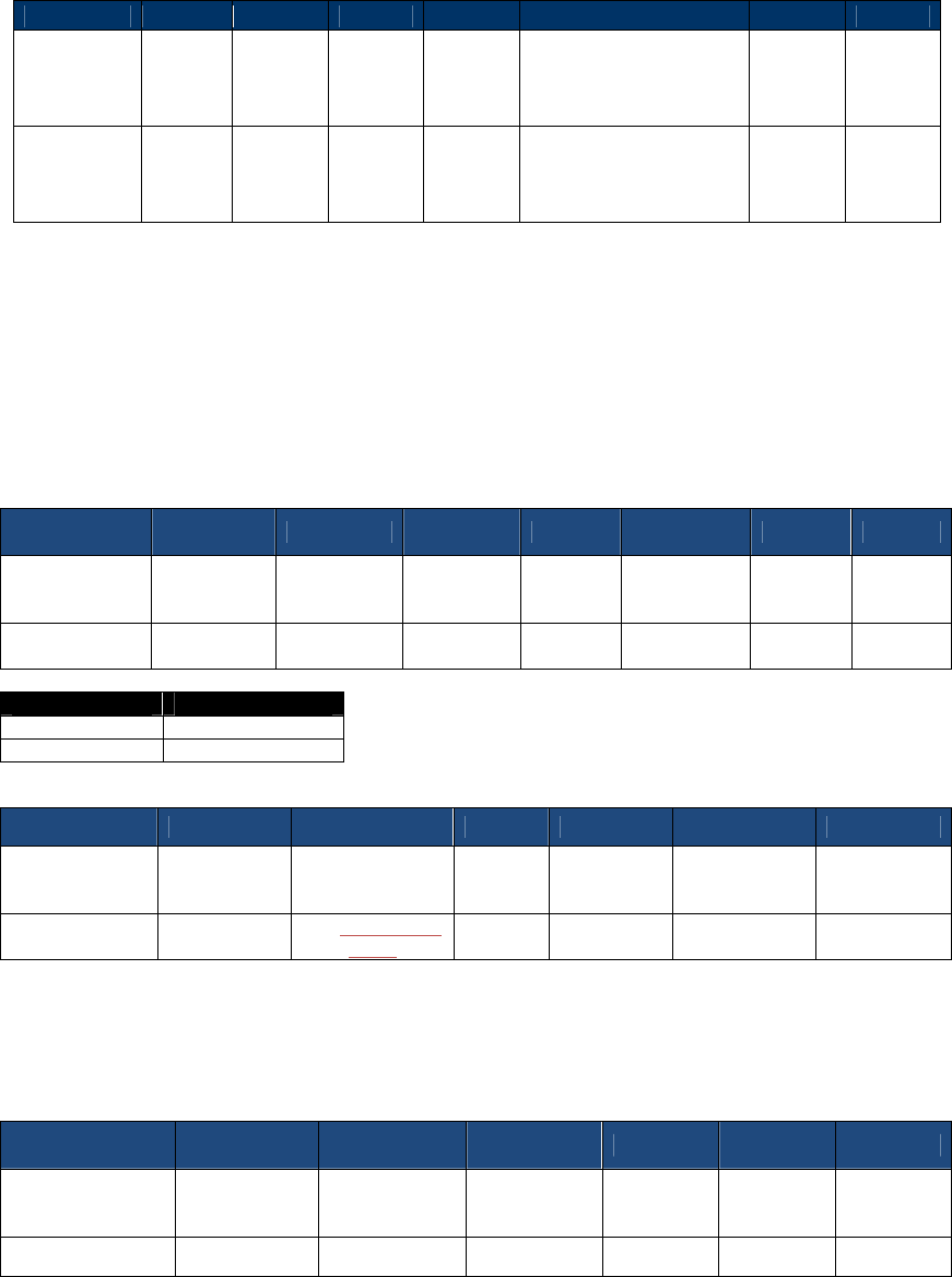
NEO Interface Developers Guide
290
Actual Data is less than 8-Byte Boundary
Byte 0-9
Byte 10
Byte 11
Byte 12
Byte 13
Byte 14 -n
Byte 23
Byte 24
Header Tag
& Protocol
Version
Cmd Sub
Cmd
Length
(MSB)
Length
(LSB)
Encrypted Data,
Pad: n pads of 0x0n,
where n is between 1
and 8
CRC
(LSB)
CRC
(MSB)
ViVOtech2\
0 00h Varies
Varies (always multiple
of 8 bytes)
Pad example, 03h, 03h,
03h.
Varies Varies
Set Data Encryption Key Variant Type (C7-2F)
This command exists to specify the key variant type of Data encryption Key, and MUST be used
before the initial loading of the Data encryption Key into the device. The key variant type
CANNOT be changed once the Data encryption Key is present. It must remain either Data Variant
or PIN Variant.
Command Frame
Byte 0-9 Byte 10 Byte 11 Byte 12 Byte 13
Byte 14 Byte 15
Byte16
Header Tag &
Protocol
Version
Command Sub-
Command
Data
length
(MSB)
Data
length
(LSB)
Data CRC
(MSB)
CRC
(LSB)
ViVOtech2\0 C7h 2Fh 00 01
Key Variant
Type
Encryption Type
Description
0
Data Variant
1
Pin Variant
Response Frame
Byte 0-9 Byte 10 Byte 11 Byte 12
Byte 13 Byte 14 Byte 15
Header Tag &
Protocol
Version
Command Status
Data
length
(MSB)
Data length
(LSB) CRC(MSB) CRC(LSB)
ViVOtech2\0 C7h
See Status Code
Table
00 00
Get Data Encryption Key Variant Type (C7-30)
Command Frame
Byte 0-9 Byte 10 Byte 11 Byte 12 Byte 13 Byte 14 Byte15
Header Tag &
Protocol Version
Command Sub-
Command
Data length
(MSB)
Data
length
(LSB)
CRC
(MSB)
CRC
(LSB)
ViVOtech2\0 C7h 30h 00 00
Response Frame
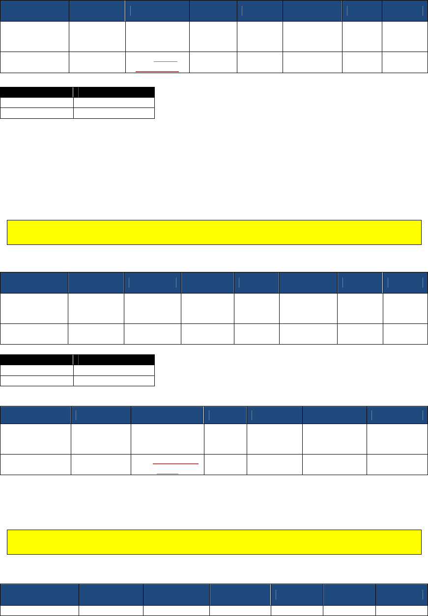
NEO Interface Developers Guide
291
Byte 0-9 Byte 10 Byte 11 Byte 12 Byte 13
Byte14 Byte 15
Byte16
Header Tag &
Protocol
Version
Command Status
Data
length
(MSB)
Data
length
(LSB)
Data1 CRC
(MSB)
CRC
(LSB)
ViVOtech2\0 C7h
See Status
Code Table 00 01
Key Variant
Type
Encryption Type
Description
0
Data Variant
1
Pin Variant
Set DUKPT Key Encryption Type (C7-32)
This command exists to specify the encryption type of Data encryption Key, and MUST be used
before the initial loading of the Data encryption Key into the device. The encryption type
CANNOT be changed once the Data encryption Key is present. It must remain either TDES or AES.
Note: This command is only supported in NSRED device. In SRED device, only TDES algorithm
is used to encrypt transaction output sensitive data.
Command Frame
Byte 0-9 Byte 10 Byte 11 Byte 12 Byte 13
Byte 14 Byte 15
Byte16
Header Tag &
Protocol
Version
Command Sub-
Command
Data
length
(MSB)
Data
length
(LSB)
Data CRC
(MSB)
CRC
(LSB)
ViVOtech2\0 C7h 32h 00 01
Encryption
Type
Encryption Type
Description
0
TDES
1
AES
Response Frame
Byte 0-9 Byte 10 Byte 11 Byte 12
Byte 13 Byte 14 Byte 15
Header Tag &
Protocol
Version
Command Status
Data
length
(MSB)
Data length
(LSB) CRC(MSB) CRC(LSB)
ViVOtech2\0 C7h
See Status Code
Table 00 00
Get DUKPT Key Encryption Type (C7-33)
Note: This command is only supported in NSRED device. In SRED device, only TDES algorithm
is used to encrypt transaction output sensitive data.
Command Frame
Byte 0-9 Byte 10 Byte 11 Byte 12 Byte 13 Byte 14 Byte15
Header Tag &
Command
Sub-
Data length
Data
CRC
CRC
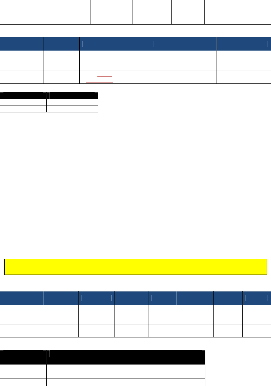
NEO Interface Developers Guide
292
Protocol Version
Command
(MSB)
length
(LSB)
(MSB)
(LSB)
ViVOtech2\0 C7h 33h 00 00
Response Frame
Byte 0-9 Byte 10 Byte 11 Byte 12 Byte 13
Byte14 Byte 15
Byte16
Header Tag &
Protocol
Version
Command Status
Data
length
(MSB)
Data
length
(LSB)
Data1 CRC
(MSB)
CRC
(LSB)
ViVOtech2\0 C7h
See Status
Code Table 00 01
Encryption
Type
Encryption Type
Description
0
TDES
1
AES
Example data (top line: command; bottom line: response)
TDES:
56 69 56 4F 74 65 63 68 32 00 C7 33 00 00 1A 9B
56 69 56 4F 74 65 63 68 32 00 C7 00 00 01 00 AC 7F
AES:
56 69 56 4F 74 65 63 68 32 00 C7 33 00 00 1A 9B
56 69 56 4F 74 65 63 68 32 00 C7 00 00 01 01 BC 5E
Set Data Encryption Enable Flag (C7-36)
This command is meant to be used once (only), to turn encryption ON permanently. It elevates
the security status of the device. This is meant to be an irreversible event.
Note: This command is supported only in non-SRED devices. In SRED devices, the reader is
always encryption-enabled and this command is unsupported.
Command Frame
Byte 0-9 Byte 10 Byte 11 Byte 12 Byte 13
Byte 14 Byte 15
Byte16
Header Tag &
Protocol
Version
Command Sub-
Command
Data
length
(MSB)
Data
length
(LSB)
Data CRC
(MSB)
CRC
(LSB)
ViVOtech2\0 C7h 36h 00 01
Encryption
Enable Flag
Encryption
Type
Description
Bit 0 0 -> CT/CL EMV Data Encryption Disable (default)
1 -> CT/CL EMV Data Encryption Enable
Bit 1 0 -> MSR/MSD Data Encryption Disable (default)
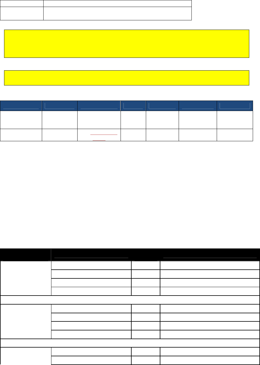
NEO Interface Developers Guide
293
1 -> MSR/MSD Data Encryption Enable
Bit 2~7
Reserve
Note: MSR/MSD Encryption Disable and EMV Encryption Enable isn’t allowed.
When MSR/MSD or EMV Encryption is enabled and Data encryption Key exists, Burst Mode is
disabled (always OFF)
Note: KIOSKIII NSRED default value is MSR/MSD Data Encryption Enable and EMV Data
Encryption Disable.
Response Frame
Byte 0-9 Byte 10 Byte 11 Byte 12
Byte 13 Byte 14 Byte 15
Header Tag &
Protocol
Version
Command Status
Data
length
(MSB)
Data length
(LSB) CRC(MSB) CRC(LSB)
ViVOtech2\0 C7h
See Status Code
Table 00 00
When Data Encryption is disabled, device will always respond plaintext data
When Data Encryption is enabled, device will output data as follows:
(1) When Data encryption Key does not exist, the commands below will respond plaintext
data for NSRED device, respond status code 0x90 and no data for SRED device.
(2) When Data encryption Key exists and is valid, the commands below will respond
encrypted data.
(3) When Data encryption Key exists and exhausted, the commands below will respond
status code 0x91 and no data.
Commands:
(1) Activate Transaction Command (02-01/02-40)
(2) Get Transaction Result Command (03-00/03-40)
Device Current Status/Command Setting/Device Operation/Output Matrix
(Data encryption Key exists and valid)
Current Encryption
Status Command Encryption Setting
Device
Operation
Output after Setting
MSR/MSD_OFF,
EMV_OFF
0x00
MSR/MSD_OFF, EMV_OFF (0x00)
Keep MSR/MSD plaintext, EMV plaintext
MSR/MSD _OFF, EMV _ON (0x01)
Refuse MSR/MSD plaintext, EMV plaintext
MSR/MSD ON, EMV_OFF (0x02) Update MSR/MSD encryption, EMV plaintext
MSR/MSD _ON, EMV_ON (0x03) Update MSR/MSD encryption, EMV encryption
MSR/MSD_ON,
EMV_OFF
0x02
MSR/MSD_OFF, EMV_OFF (0x00)
Refuse MSR/MSD encryption, EMV plaintext
MSR/MSD _OFF, EMV _ON (0x01)
Refuse MSR/MSD encryption, EMV plaintext
MSR/MSD ON, EMV_OFF (0x02) Keep MSR/MSD encryption, EMV plaintext
MSR/MSD _ON, EMV_ON (0x03) Update MSR/MSD encryption, EMV encryption
MSR/MSD_ON,
EMV_ON
MSR/MSD_OFF, EMV_OFF (0x00)
Refuse MSR/MSD encryption, EMV encryption
MSR/MSD _OFF, EMV _ON (0x01)
Refuse MSR/MSD encryption, EMV encryption
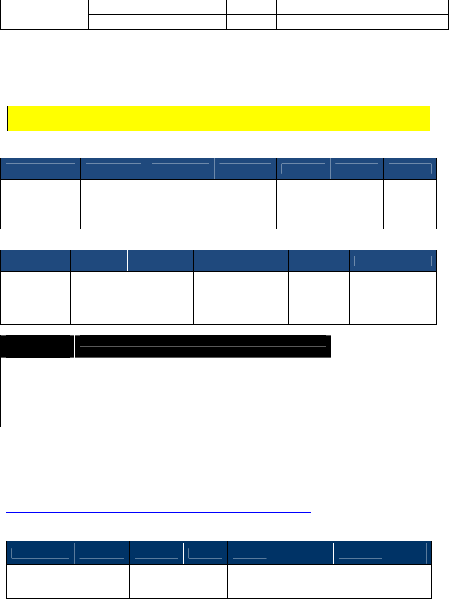
NEO Interface Developers Guide
294
0x03
MSR/MSD ON, EMV_OFF (0x02) Refuse MSR/MSD encryption, EMV encryption
MSR/MSD _ON, EMV_ON (0x03) Keep MSR/MSD encryption, EMV encryption
Get Data Encryption Enable Flag (C7-37)
Note: This command is only supported in Non-SRED version devices, not supported in SRED
version devices.
Command Frame
Byte 0-9 Byte 10 Byte 11 Byte 12 Byte 13 Byte 14 Byte15
Header Tag &
Protocol Version
Command Sub-
Command
Data length
(MSB)
Data
length
(LSB)
CRC
(MSB)
CRC
(LSB)
ViVOtech2\0 C7h 37h 00 00
Response Frame
Byte 0-9 Byte 10 Byte 11 Byte 12 Byte 13
Byte14 Byte 15
Byte16
Header Tag &
Protocol
Version
Command Status
Data
length
(MSB)
Data
length
(LSB)
Data1 CRC
(MSB)
CRC
(LSB)
ViVOtech2\0 C7h
See Status
Code Table 00 01
Encryption
Enable Flag
Encryption
Type
Description
Bit 0 0 -> CT/CL EMV Data Encryption Disable (default)
1 -> CT/CL EMV Data Encryption Enable
Bit 1 0 -> MSR/MSD Data Encryption Disable (default)
1 -> MSR/MSD Data Encryption Enable
Bit 2~7
Reserve
Set MSR Secure Parameters (C7-38)
This command allows setting parameters that determine encrypted output from MSR sessions.
Use it to force encryption data output to include various kinds of data per Enhanced Encrypted
MSR Data Output When Encryption is Turned On with C7-38 Command. Consult the table in that
Appendix (A.13) to see the types of output that can occur.
Command Frame
Byte 0-9 Byte 10 Byte 11 Byte 12
Byte 13
Byte 14 …
Byte 14+n-1
Byte 14+n
Byte
15+n
Header Tag &
Protocol
Version
Command Sub-
Command
Data
Length
(MSB)
Data
Length
(LSB)
Data
CRC (LSB)
CRC
(MSB)

NEO Interface Developers Guide
295
ViVOtech2\0 C7h 38h 00h 05h
MSR Secure
Parameters
TVL
MSR Secure Parameters TVL objects
Tag
Data Object Name
Description
Format
Length
DFDE04
MSR Encryption Option
Encryption Option (Forced encryption
or not)
Bit 0: T1 force encrypt
Bit 1: T2 force encrypt
Bit 2: T3 force encrypt
Bit 3: T3 force encrypt when card
type is 80
Default value is 0x08.
b
1
Response Frame
Byte 0-9 Byte 10 Byte 11 Byte 12
Byte 13
Byte 14 …
Byte 14+n-1
Byte 14+n
Byte 15+n
Header Tag
& Protocol
Version
Command
Status
Code
Data
Length
(MSB)
Data
Length
(LSB)
Data CRC
(MSB)
CRC
(LSB)
ViVOtech2\
0
C7h
See Status
Code Table
ViVOtech2\
0 C7h 38h 00h 05h
MSR Secure
Parameters
TVL
Get MSR Secure Parameters (C7-39)
This command can get parameters from flash setting.
Command Frame
Byte 0-9 Byte 10 Byte 11 Byte 12
Byte 13
Byte 14 …
Byte 14+n-1
Byte 14+n
Byte
15+n
Header Tag &
Protocol
Version
Command Sub-
Command
Data
Length
(MSB)
Data
Length
(LSB)
Data
CRC (LSB)
CRC
(MSB)
ViVOtech2\0 C7h 39h 00h 03h
MSR Secure
Parameters
TVL
MSR Secure Parameters TVL objects
Tag
Data Object Name
Description
Format
Length
DFDE04
MSR Encryption Option
Encryption Option (Forced encryption
or not)
Bit 0: T1 force encrypt
Bit 1: T2 force encrypt
Bit 2: T3 force encrypt
Bit 3: T3 force encrypt when card
type is 80
Default value is 0x08.
b
1
Response Frame
Byte 0-9 Byte 10 Byte 11 Byte 12
Byte 13
Byte 14 …
Byte 14+n-1
Byte 14+n
Byte 15+n
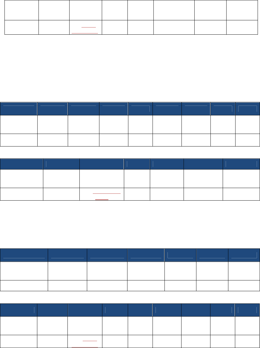
NEO Interface Developers Guide
296
Header Tag
& Protocol
Version
Command
Status
Code
Data
Length
(MSB)
Data
Length
(LSB)
Data CRC
(MSB)
CRC
(LSB)
ViVOtech2\
0
C7h
See Status
Code Table
00h 05h TLV
Key Injection and Related Commands
Set Remote Key Injection Timeout (C7-2D)
Command Frame
Byte 0-9 Byte 10 Byte 11 Byte 12 Byte 13
Byte14 Byte 15 Byte 16
Byte17
Header Tag
& Protocol
Version
Command
Sub-
Command
Data
length
(MSB)
Data
length
(LSB)
Data1 Data2 CRC
(MSB)
CRC
(LSB)
ViVOtech2\0
C7h 2Dh 00 02
Timeout
(MSB)
Timeout
(LSB)
Response Frame
Byte 0-9 Byte 10 Byte 11 Byte 12
Byte 13 Byte 14 Byte 15
Header Tag &
Protocol
Version
Command Status
Data
length
(MSB)
Data length
(LSB) CRC(MSB) CRC(LSB)
ViVOtech2\0 C7h
See Status Code
Table 00 00
Timeout is in second, value scope is [120, 3600]. If timeout, remote key injection is canceled.
Get Remote Key Injection Timeout (C7-2E)
Command Frame
Byte 0-9 Byte 10 Byte 11 Byte 12 Byte 13 Byte 14 Byte15
Header Tag &
Protocol Version
Command Sub-
Command
Data length
(MSB)
Data
length
(LSB)
CRC
(MSB)
CRC
(LSB)
ViVOtech2\0 C7h 2Eh 00 00
Response Frame
Byte 0-9 Byte 10 Byte 11 Byte 12
Byte 13
Byte14 Byte 15 Byte 16
Byte17
Header Tag
& Protocol
Version
Command
Status
Data
length
(MSB)
Data
length
(LSB)
Data1 Data2 CRC
(MSB)
CRC
(LSB)
ViVOtech2\0
C7h
See Status
Code Table
00 00
Timeout
(MSB)
Timeout
(LSB)
Timeout is in second, value scope is [120, 3600]. If timeout, remote key injection is canceled.
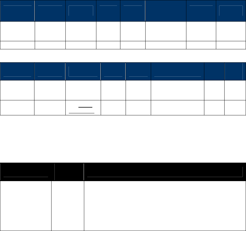
NEO Interface Developers Guide
297
Check DUKPT Keys (81-02)
This command checks and returns the state of the DUKPT key associated with each slot.
Slot 2: RKI-KEK (NSRED and SRED device support, use in Remote Key Injection)
Slot 3: MAC DUKPT Key (SRED device support, for future use)
Slot 5: Data encryption Key (NSRED and SRED device support, use to encrypt transaction output
sensitive data)
Command Frame
Byte 0-9 Byte 10 Byte 11 Byte 12
Byte 13
Byte 14 ~
Byte 14+n-1 Byte 14+n
Byte 15+n
Header Tag
& Protocol
Version
Command
Sub-
Command
Data
Length
(MSB)
Data
Length
(LSB)
Data CRC (LSB)
CRC (MSB)
ViVOtech2\0
81h 02h 00h 00h None
Response Frame
Byte 0-9 Byte 10 Byte 11 Byte 12
Byte 13
Byte 14 ~ 13+n Byte
14+n
Byte
15+n
Header Tag
& Protocol
Version
Command Status Code
Data
Length
(MSB)
Data
Length
(LSB)
Data
CRC
(MSB)
CRC
(LSB)
ViVOtech2\
0 81h See Status
Code Table 00h 00h or
0Ch
Nothing
or Key States
If successful, the returned Status Code is 00h and the response data will contain the key states
for 12 slots. Most of these slots are reserved for future use. Only the supported slot indexes will
contain key states. The format of the data returned on success is given below.
Response Data (When Status is OK)
Data Item Length
(bytes) Description
Key States 12 (0Ch) This data item contains the Key States for 12 DUKPT Key slots.
Each byte represents the Key State for a single slot.
Possible values for each Key State are:
00h: Unused (Slot is supported but no key injected)
01h: Valid (A valid key is available in this slot)
02h: End of Life (The key on this slot has reached end of life)
FFh: Not Available (This slot is not supported)
If the command is not successful, then the Status Code will not be 00h and no data is returned.
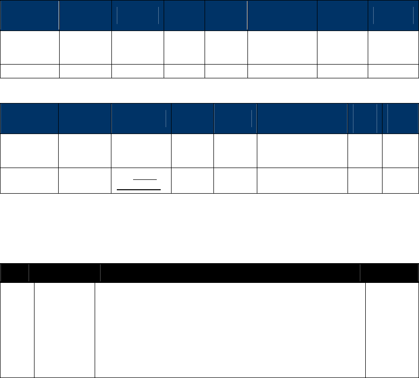
NEO Interface Developers Guide
298
Check DUKPT Key (81-04)
This command checks whether a valid DUKPT key is stored at the specified slot and if a valid key
is found then some basic information related to the type of key is returned. The actual Key data
is never returned.
This command can be used to check whether a key is already present before injecting a key in a
slot to prevent overwriting an existing DUKPT key.
Slot 2: RKI-KEK (NSRED and SRED device support, use in Remote Key Injection)
Slot 3: MAC DUKPT Key (SRED device support, for future use)
Slot 5: Data encryption Key (NSRED and SRED device support, use to encrypt transaction output
sensitive data)
Command Frame
Byte 0-9 Byte 10 Byte 11 Byte 12
Byte 13
Byte 14 …
Byte 14+n-1 Byte 14+n
Byte 15+n
Header Tag
& Protocol
Version
Command
Sub-
Command
Data
Length
(MSB)
Data
Length
(LSB)
Data CRC (LSB)
CRC (MSB)
ViVOtech2\0
81h 04h 00h 01h Key Slot
Response Frame
Byte 0-9 Byte 10 Byte 11 Byte 12
Byte 13
Byte 14-13+n Byte
14+n
Byte
15+n
Header Tag
& Protocol
Version
Command Status Code
Data
Length
(MSB)
Data
Length
(LSB)
Data
CRC
(MSB)
CRC
(LSB)
ViVOtech2\
0 81h See Status
Code Table 00h variable
Nothing
or Key States
If the Command Frame is valid, then the Status Code will be OK and the response data will
contain the key state and other key related data as shown in the following table. If the
Command Frame is not valid, then the Status Code will not be OK and no data will be returned.
Response Data (When Status is OK)
Byte Field Name Description Encoding
0 Key State Key State for the DUKPT key associated with the specified slot.
Possible values for the Key State are:
00h: Unused (Slot is supported but no key injected)
01h: Valid (A valid key is available in this slot)
02h: End of Life (The key on this slot has reached end of
life)
FFh: Not Available (This slot is not supported)
Mandatory Field.
Binary

NEO Interface Developers Guide
299
Byte Field Name Description Encoding
1-2 Key Usage ‘K0’ – Use to encrypt or wrap other keys
‘D0’ – Use to encrypt Data
‘M0’ – Use to do MAC Verification (only SRED device support)
Present only if key state indicates a valid key.
2AN
3 Algorithm ‘A’, hex 0x41, AES
‘T’, hex 0x54. Triple DES
‘D’, hex 0x44. Single DES
Present only if key state indicates a valid key.
1AN
4 Mode of Use
'N' No special restrictions
‘B’ Both Encryption and Decryption
'E' Encryption only
'D' Decryption only
Present only if key state indicates a valid key.
1AN
5-6 Key Version
Number
‘00’, hex 0x3030.
If set to ‘00’ key version number is not used. Key version is not
supported in this version of the specifications
Present only if key state indicates a valid key.
2AN
Get DUKPT Key Serial Number (KSN) (81-0A)
Host can use this command to retrieve the KSN of the selected DUKPT key.
Slot 2: RKI-KEK (NSRED and SRED device support, use in Remote Key Injection)
Slot 3: MAC DUKPT Key (SRED device support, for future use)
Slot 5: Data encryption Key (NSRED and SRED device support, use to encrypt transaction output
sensitive data)
Command Frame
Byte 0-9
Byte 10
Byte 11
Byte 12
Byte 13
Byte 14
Byte 15
Byte 16
Header Tag
& Protocol
Version
Command Sub-
Command
Data
Length
(MSB)
Data
Length
(LSB)
Key Index CRC
(LSB)
CRC
(MSB)
ViVOtech2\0
81h
0Ah
00h
01h
Key slot
Response Frame
Byte 0-9 Byte 10 Byte 11 Byte 12 Byte 13
Byte
14 … Byte
14+n-1
Byte
14+n
Byte
15+n
Header Tag
& Protocol
Version
Command
Status Code
Data Length
(MSB)
Data Length
(LSB)
Data CRC
(MSB)
CRC
(LSB)
ViVOtech2\0
81h
Status Code
00h
variable
KSN
If the Command Frame is valid, the slot was supported and the DUKPT Key is valid, the Status
Code will be OK and the data portion will have the content described below. If the Command
Frame is not valid or the slot is unsupported or DUKPT Key is not valid, then the Status Code will
not be OK and no data will be returned.

NEO Interface Developers Guide
300
Get KSN Response Data
Data Item Length
(bytes) Description
KSN 20
KSN of selected DUKPT key
Format: ASCII (no null terminator)
NEO Interface Developers Guide
301
11.0 Improved Collision Detection
Issues with Standard Collision Detection
This firmware supports the EMV Contactless Communication Protocol Specification. While the
EMV specification defines collision detection, there are often physical constraints which prevent
collision detection resolving within the timing limits outlined in the specification.
For instance, multiple cards in the field cannot always be detected reliably. If a particular card
responds more quickly to RF polling, or if a card has a stronger antenna, then the signal will lock
to that card. (This problem is not limited to ID TECH equipment.) Card geometry can also be a
major factor in collision detection.
The following bullets explain some of the difficulties associated with multiple card presentation:
When a single type A and single type B card are presented side-by-side the reader will
detect collisions without much difficulty:
When two cards are stacked on top of one another, the faster card or the card that is closer
to the PCD will be activated. This is because the slower card or the card that is further from
the PCD suffers insufficient power, interference from the other card, or timing that falls
outside the boundaries defined in the EMV specification.
Presenting two cards of the same type side by side (e.g. A || A) will suffer from the same
problems described in the previous bullet, because the RF power draw from one card can
negatively impact the communication and/or power of the other card.
NEO Interface Developers Guide
302
The six possible multiple card presentation scenarios are listed in the table below.
Scenario
Card Type
Orientation
1
A / B
Stacked
2
A / B
Fanned
3
A / A
Stacked
4
A / A
Fanned
5
B / B
Stacked
6
B / B
Fanned
Note: Card Type B / B (scenarios 5 & 6) are inherently difficult to detect. When multiple
type B cards are presented they should detune one another. If there is minimal detuning then
no collision would be detected.
Collision Detection Modes
The firmware features two mutually-exclusive collision detection modes, Standard Collision
Detection and Improved Collision Detection, which are described in the subsections below.
11.1.1.1 Standard Collision Detection
Standard Collision Detection, also known as EMEA Anti-Collision Detection, is enabled by default,
as it maximizes the chances of completing a transaction. In this mode, if a collision event is
detected, the reader will back off and resume polling.
Media removal events are handled as per the EMEA requirements for collision. When detecting a
collision a media removal UI event is triggered (all LEDs off, 2 tone alert, and appropriate
message for LCD equipped units), a small delay is then introduced before returning to polling.
Note:
It is important to understand that the procedure outlined above will repeat if the collision is
not resolved. Also, the media removal event only operates when the EMEA UI is enabled (tag
'FF F8' = '03'). Finally, this procedure occurs automatically without interaction from the
integrated system and will operate for the duration of the Timeout period, as set by Activate
Transaction.

NEO Interface Developers Guide
303
The reader will then continue to retry the transaction; until either, the collision issue has been
resolved (and a transaction takes place), or until the transaction timeout expires. In the latter
case, the timeout will contain the timeout status (0x08) and timeout cause in the data field
(0x21, collision error).
Note: In this mode, if a collision is detected, the reader will interpret further
‘Communication Error’ or ‘Card Not Present’ events as being caused by collision.
11.1.1.2 Improved Collision Detection
Enabling this mode disables Standard Collision Detection mode and changes reader behavior:
1. While polling, the reader will attempt to find the PICC using the standard polling
method.
2. If a collision is detected, the reader will abort the transaction and notify the POS.
3. It will report this with an error in the data field of its response (0x21, collision error).
Tag DF7F enables/disables Improved Collision Detection. When this tag is set to zero (default
value), Improved Collision mode is disabled. When this tag is set to another value (1-255),
Improved Collision mode is enabled.
When Improved Collision mode is enabled, the DF7F tag value defines the number of successful
sequential polling attempts required for signal lock. For example, if tag DF7F = 3, then the
reader must detect a card successfully three times in a row before the firmware decides this is a
successful polling attempt. Given the same conditions, the reader must fail to detect a card
three times in a row before the firmware decides this is a 'card not present' polling attempt.
To reiterate, Improved Collision Detection requires a specified number of polling attempts to
complete without an EMV collision event before the RF signal is locked to a specific card. If an
EMV collision event is reported, the transaction will end and return a collision status code.
The following table summarizes the tag-related information provided above.
Feature Tag Length
Value Notes
Improved Collision
Detection
DF7F
1 byte
0 = default
Improved Collision Detection Disabled.
(i.e. one successful polling attempt is
sufficient for signal lock)
1 – 255
Improved Collision Detection Enabled.
Number of successful sequential polling
attempts required for signal lock.
In this new mode, the collision scenarios have been improved in the following manner:
4. Increased sensitivity to improve collision detection generally. Previously, silent card and
garbled receive were not identified in the same manner as a standard collision.
5. If the transaction times out due to any of the collision methods described previously, the
serial response will reflect this in its error state, with Status Code 0x08 (Time Out) and Error
Code 0x21 (Collision Error).

NEO Interface Developers Guide
304
Example
Assume a reader has enabled Improved Collision Detection with tag DF7F = 3. When two cards
are placed within view of the reader, the following polling results are obtained.
Polling Attempt
1
2
3
Polling Result
OK
OK
L1C
These results show that the first and second polling attempts are successful; but, the third
polling attempt reports an EMV L1 collision (e.g. a slower or weaker signal). This collision
detection would result in immediate termination of the transaction and the reader returning a
collision status code. In contrast, if Standard Collision Detection mode was enabled instead,
then the reader would accept the first attempt and the transaction would proceed with the first
card detected.
NEO Interface Developers Guide
305
12.0 Kiosk III Boot Loader
This section only applies to the Kiosk III reader, describes the designation of Kiosk III boot loader
version from 'KIOSKIII-BL-V3.00.010' on.
The Boot Loader controls initial operation after reset and also provides the means to program
the Flash memory,
Kiosk III has two types of products: Non-SREd and SRED. This boot loader can be used in both
types of Kiosk III device.
Description
KIOSK III Boot Loader controls initial operation after reset and also provides the means to
program the flash memory which operate over both RS232 and USB interface.
KIOSK III uses a freescale K21 chip with 1M bytes embedded flash. The flash is divided into three
zones: boot-loader, configuration and application. As for boot-loader zone, it is divided into
three zones: BIM(boot image manager), boot-loader 1 and boot-loader 2. BIM cannot be updated,
application can be updated by boot-loader, boot-loader1 can be updated by boot-loader2, and
boot-loader2 can be updated by boot-loader1.
Boot loader code is executed every time the reader is powered on or reset.
If a valid user program is not found, the firmware downloader is invoked. If a valid user program
is found, then the execution control is transferred to it after 3 seconds waiting, during this
waiting time, user can invoke firmware downloader by sending boot load commands.
The firmware data to be updated to device is protected by firmware RSA key, which is RSA key
under RSA-2048. Firmware data is encrypted by firmware RSA private key, and must be
authenticated by firmware RSA public key when the data are all loaded into device. The
updated firmware data won't be valid before authentication succeed. The firmware RSA public
key is injected into device during manufacturing.
Boot Procedure
After any reset or power up the Kiosk III boot loader is the first code executed. Boot loader then
check whether the main application exists. If the application exists, boot loader waits 3 seconds
for user to send boot load commands. If user send boot load commands inside the waiting time,
the firmware downloader is invoked and a firmware image is to be downloaded. If user does not
send boot loader commands inside the waiting time, then boot loader passes control to the main
application. If the main application does not exist then boot loader invoke the firmware
downloader and waits for a firmware image to be downloaded.
After power up or reboot, boot-loader gets the control of the chip, and then does the following
tasks in order.
a) BIM reads and compares boot-loader1 and boot-loader2 flag, selects the newer and passes
the control to it.
b) The selected boot-loader check the reason of reboot. If the reboot reason is that the
application did the reboot in favor of entering boot-loader mode, then go to step f).
c) Check whether an application exists in application zone or not. If not, go to step f).
d) Wait boot loader commands from host for 3 seconds, if received boot load command,
invoke firmware downloader; if boot load command not received, go to e).

NEO Interface Developers Guide
306
e) Transfer the control of the chip to application.
f) wait for boot-loader commands from host.
Communication Protocol
All Firmware downloader commands are following Protocol 2. .
Firmware Downloader File Name Format
Firmware download file name is formatted as: '[firmware version]_[clear/encrypted]_[port].txt'
[firmware version]:
If the file is to update application, then [firmware version] is application main version. For
example: 'NEO v1.00.012'.
If the file is to update boot loader, then [firmware version] is boot loader version. for
example: 'KIOSKIII-BL-V3.00.010'.
If the file is to update both, then [firmware version] is showed as application main version
and boot loader version linked with '&'. For example: ' NEO v1.00.012 & KIOSKIII-BL-
V3.00.010'
[clear/encrypted]:
'ENC' means this download file is encrypted
'CLR' means this download file is not encrypted
If file name not marked with 'ENC' or 'CLR', that is encrypted file.
If firmware key is valuable in device, please use encrypted download file.
If firmware key is not valuable in device, please use clear download file.
Note: Encrypted download files are generally used in firmware updating. Clear download
files are only prepared for device recovery in special accidents.
[port]:
If the file is for RS232 port, then [port] is 'RS232'. If the file is for USBHID port, then [port]
is 'USBHID'.
' NEO v1.00.016_CLR_RS232.txt'
' NEO v1.00.016_CLR_USBHID.txt'
' NEO v1.00.016_ENC_RS232.txt '
'NEO v1.00.016_ENC_ USBHID.txt'
' KIOSKIII-BL-V3.00.014_CLR_RS232.txt'
' KIOSKIII-BL-V3.00.014_CLR_USBHID.txt'
' KIOSKIII-BL-V3.00.014_ENC_RS232.txt'
'KIOSKIII-BL-V3.00.014_ENC_ USBHID.txt'
' NEO v1.00.016 & KIOSKIII-BL-V3.00.014_CLR_RS232.txt'
' NEO v1.00.016 & KIOSKIII-BL-V3.00.014_CLR_USBHID.txt'
' NEO v1.00.016 & KIOSKIII-BL-V3.00.014_ENC_RS232.txt'
' NEO v1.00.016 & KIOSKIII-BL-V3.00.014_ENC_USBHID.txt'

NEO Interface Developers Guide
307
Firmware Downloader Data Format
Firmware download file is coded in ASCII text. Firmware download commands and expected
responses are embed in text file one command per line. Host can retrieve each command in
order and convert the command from ASCII code to hex data then send them to Kiosk III device,
then compare the response from Kiosk III device with expected response next to the command in
text file.
Firmware download file data format is as: '[prefix][data]'
Prefix
Data Example
Description
'#'
'XXXXX...'
Data follow '#' is comments only.
'<START:'
None
No data needed, just specify the
starting of download.
'TIMEOUT:'
'1000'
Recommended timeout between
command and response, unit is ms.
'SLEEP:'
'2000'
Host sleep, unit is ms.
'SEND:'
' 5669564F746563683200C7110000F23D'
Data is the command to be sent to
device.
Note: Data format is different between
RS232 port and USBHID port.
'WAIT:'
' 5669564F746563683200C7000000866E'
Data is the response expected to the
command above line.
Note: Data format is different between
RS232 port and USBHID port.
'END>'
None
No data needed, just specify the ending
of download.
Examples:
NEO v1.00.012_RS232.txt
#RS232 version
<START:
TIMEOUT:1000
SEND:5669564F746563683200C7410000ACF3
SLEEP:2000
SEND:5669564F746563683200C7110000F23D
WAIT:5669564F746563683200C7000000866E
SEND:5669564F746563683200C7120001014A91
WAIT:5669564F746563683200C7000000866E
SEND: 5669564F746563683200C71301008A8D92719D9D.......
WAIT:5669564F746563683200C7000000866E
......
......
......
WAIT:5669564F746563683200C7000000866E
SEND:5669564F746563683200C71500083230313530393234BE8B
WAIT:5669564F746563683200C7000000866E
SEND:5669564F746563683200C716000077AD
WAIT:5669564F746563683200C7000000866E
END>
NEO v1.00.012_USBHID.txt
#USBHID version
<START:

NEO Interface Developers Guide
308
TIMEOUT:1000
SEND:015669564F746563683200C7410000ACF300000000000......
SLEEP:2000
SEND:015669564F746563683200C7110000F23D00000000000......
WAIT:015669564F746563683200C7000000866E00000000000......
......
......
......
SEND: 015669564F746563683200C71500083230313530393234BE8B000000000......
WAIT:015669564F746563683200C7000000866E000000000000......
SEND:015669564F746563683200C716000077AD000000000000......
WAIT:015669564F746563683200C7000000866E000000000000......
END>
Download Firmware Steps
When host wants to update firmware to Kiosk III device, please do as following steps:
step 1: Power on Kiosk III device.
step 2: Configure the communication ports and establish connection between host and Kiosk III
device.
step 3: Host selects the right firmware download file, parses data, then finishes the whole
commands.
step 4: End
Firmware Downloader Commands
Enter Boot Loader Process from Main Application (C7-41)
Host must use this command to let reader reboot into boot loader mode if reader is running in
main application. No response for this command and just reset reader immediately.
If reader is running in boot loader, this command is not needed.
Command Frame
Byte 0-9
Byte 10
Byte 11
Byte 12
Byte 13
Byte 14
Byte 15
Header Tag &
Protocol Version
Command Sub-Command
Data
Length
(MSB)
Data
Length
(LSB)
CRC (LSB)
CRC (MSB)
ViVOtech2\0
C7h
41h
00h
00h
Get Boot Loader Version (C7-10)
This command is used to retrieve the boot loader version.
Command Frame
Byte 0-9
Byte 10
Byte 11
Byte 12
Byte 13
Byte 14
Byte 15
NEO Interface Developers Guide
309
Header Tag &
Protocol Version
Command Sub-Command
Data
Length
(MSB)
Data
Length
(LSB)
CRC (LSB)
CRC (MSB)
ViVOtech2\0
C7h
10h
00h
00h
Response Frame
Byte 0-9 Byte 10 Byte 11 Byte 12 Byte 13
Byte
14 ...Byte
13+n
Byte 14+n
Byte 15+n
Header Tag &
Protocol Version
Command
Status Code
Data Length
(MSB)
Data Length
(LSB)
Data
CRC (MSB)
CRC (LSB)
ViVOtech2\0 C7h
See Status
Code Table 00h 00h
See Below
Response data is the version of the boot loader.
For example: ' KIOSKIII-BL-V1.00.001'
Start Update Process (C7-11)
This is the first command sent by host to open a firmware update process.
Command Frame
Byte 0-9
Byte 10
Byte 11
Byte 12
Byte 13
Byte 14
Byte 15
Header Tag &
Protocol Version
Command Sub-Command
Data
Length
(MSB)
Data
Length
(LSB)
CRC (LSB)
CRC (MSB)
ViVOtech2\0
C7h
11h
00h
00h
Response Frame
Byte 0-9
Byte 10
Byte 11
Byte 12
Byte 13
Byte 14
Byte 15
Header Tag &
Protocol Version
Command Status Code
Data
Length
(MSB)
Data
Length
(LSB)
CRC (LSB)
CRC (MSB)
ViVOtech2\0 C7h
See Status
Code Table
00h 00h
Erase Boot/Application Space(C7-12)
This command is used to erase corresponding zones in the flash.
Command Frame
Byte 0-9
Byte 10
Byte 11
Byte 12
Byte 13
Byte 14
Byte 14
Byte 15
Header Tag &
Protocol
Version
Command
Sub-
Command
Data
Length
(MSB)
Data
Length
(LSB)
Data
CRC (LSB)
CRC
(MSB)
ViVOtech2\0
C7h
12h
00h
01h
See Below
Data: 0x01 Erase application space
0x02 Erase boot loader space
0x03 Erase application and boot loader space
When this command is received, reader will store a dirty flag in flash.
Response Frame
NEO Interface Developers Guide
310
Byte 0-9
Byte 10
Byte 11
Byte 12
Byte 13
Byte 14
Byte 15
Header Tag &
Protocol Version
Command Status Code
Data
Length
(MSB)
Data
Length
(LSB)
CRC (LSB)
CRC (MSB)
ViVOtech2\0 C7h
See Status
Code Table 00h 00h
Send Encrypted Firmware Check Value(C7-13)
This command is used to send firmware check-value to the device.
Command Frame
Byte 0-9 Byte 10 Byte 11 Byte 12
Byte 13
Byte 14 -
Byte 269 Byte 270
Byte 271
Header Tag &
Protocol
Version
Command
Sub-
Command
Data
Length
(MSB)
Data
Length
(LSB)
Data
CRC (LSB)
CRC
(MSB)
ViVOtech2\0
C7h
13h
01h
00h
See Below
In this command, data length must be 256 bytes. the 256 bytes data are encrypted firmware
check value. It is a SHA256 digest of the plaint firmware encrypted by firmware RSA public key.
Response Frame
Byte 0-9
Byte 10
Byte 11
Byte 12
Byte 13
Byte 14
Byte 15
Header Tag &
Protocol Version
Command Status Code
Data
Length
(MSB)
Data
Length
(LSB)
CRC (LSB)
CRC (MSB)
ViVOtech2\0 C7h
See Status
Code Table 00h 00h
Send Plaint Firmware Check Value(C7-23)This command is used to send firmware check-value to
the device.
This command is supported later than KIOSKIII-BL-V3.00.007.
Command Frame
Byte 0-9 Byte 10 Byte 11 Byte 12
Byte 13
Byte 14 -
Byte 269 Byte 270
Byte 271
Header Tag &
Protocol
Version
Command
Sub-
Command
Data
Length
(MSB)
Data
Length
(LSB)
Data
CRC (LSB)
CRC
(MSB)
ViVOtech2\0
C7h
23h
00h
20h
See Below
In this command, data length must be 32 bytes. the 32 bytes data are plaint firmware check
value. It is a SHA256 digest of the plaint firmware.
Response Frame
Byte 0-9
Byte 10
Byte 11
Byte 12
Byte 13
Byte 14
Byte 15
Header Tag &
Protocol Version
Command Status Code
Data
Length
(MSB)
Data
Length
(LSB)
CRC (LSB)
CRC (MSB)
ViVOtech2\0 C7h
See Status
Code Table
00h 00h
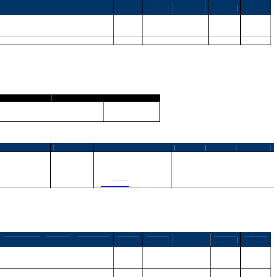
NEO Interface Developers Guide
311
Send Firmware Data (C7-14)
This command is sent by host to program specified address in application zone or boot loader
zone. One command can send 2048 bytes data block which is 2048 bytes plaint firmware data
XOR with the 32 bytes firmware check value.
Command Frame
Byte 0-9 Byte 10 Byte 11 Byte 12
Byte 13
Byte 14 -
Byte 2065 Byte 2066
Byte
2067
Header Tag &
Protocol
Version
Command
Sub-
Command
Data
Length
(MSB)
Data
Length
(LSB)
Data
CRC (LSB)
CRC
(MSB)
ViVOtech2\0
C7h
14h
01h
00h
See Below
In this command, data length must be 2052 bytes:
The first 4 bytes are the address where the firmware data in this command should be put in
reader flash.
The other 2048 bytes are firmware plaint data XOR with the 32 bytes firmware check value and
will be XOR with 32 bytes firmware check value by reader, then reader update the plaint
firmware data into the right address got from the first 4 bytes.
Item
Start Address
End Address
Main Application
0x00020000
0x000B7FFF
Boot Loader 1
0x00008000
0x00013FFF
Boot Loader 2
0x00014000
0x0001FFFF
Response Frame
Byte 0-9
Byte 10
Byte 11
Byte 12
Byte 13
Byte 14
Byte 15
Header Tag &
Protocol Version
Command Status Code
Data
Length
(MSB)
Data
Length
(LSB)
CRC (LSB)
CRC (MSB)
ViVOtech2\0 C7h
See Status
Code Table 00h 00h
End Update Process (C7-15)
This is the last command sent by host to close a firmware update process.
Command Frame
Byte 0-9 Byte 10 Byte 11 Byte 12 Byte 13
Byte 14 -
Byte 21
Byte 22 Byte 23
Header Tag &
Protocol
Version
Command
Sub-
Command
Data
Length
(MSB)
Data
Length
(LSB)
Data
CRC
(LSB)
CRC
(MSB)
ViVOtech2\0
C7h
15h
00h
08h
See Below
In this command, data length must be 8 bytes: 'YYYYMMDD', exp: '20150605'.
When this command is received, reader will do the following:
1. Clear the dirty flag.
2. If updated firmware is main application, reader then encrypts the firmware check value by
the 32 bytes inherent key using AES256 algorithm(Inherent key is a 32-byte random number
that protected by K21 tamper). The 32 bytes encrypted check value is stored in flash. If
updated firmware is boot loader, the check value is ignored, will not be store in flash.
3. If updated firmware is boot loader, reader stores boot loader sequence number and time
stamp in flash.

NEO Interface Developers Guide
312
Response Frame
Byte 0-9
Byte 10
Byte 11
Byte 12
Byte 13
Byte 14
Byte 15
Header Tag &
Protocol Version
Command Status Code
Data
Length
(MSB)
Data
Length
(LSB)
CRC (LSB)
CRC (MSB)
ViVOtech2\0 C7h
See Status
Code Table 00h 00h
Start Application (C7-16)
Host can use this command to make boot loader reboot reader, and then enter main application.
No response for this command and just reset reader immediately.
Command Frame
Byte 0-9
Byte 10
Byte 11
Byte 12
Byte 13
Byte 14
Byte 15
Header Tag &
Protocol Version
Command Sub-Command
Data
Length
(MSB)
Data
Length
(LSB)
CRC (LSB)
CRC (MSB)
ViVOtech2\0
C7h
16h
00h
00h
Firmware Downloader Command Processing Flow
Firmware downloader commands must be sent to device in sequence as below.
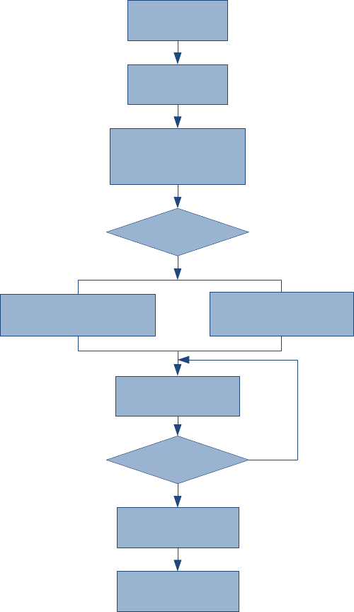
NEO Interface Developers Guide
313
Send Encrypted Firmware
Check Value
(C7-13)
Send Plaint Firmware
Check Value
(C7-23)
N
N
Y
Y
Enter Boot
Loader Process
(C7-41)
Start Update
Process
(C7-11)
Erase Boot/Application
Space
(C7-12)
Firmware Key
Valiable?
Send Firmware Data
(C7-14)
Firmware Data
Finished?
End Update Process
(C7-15)
Start Application
(C7-16)

NEO Interface Developers Guide
314
13.0 UniPay 1.5 & UniPay III Commands
Set PMC Status (F0-00)
This command is used to set Power Management status. When Power Management is On, reader
will go to LLS for power saving in Idle Time, and go to Power Off Mode when staying in LLS over
Sleep Time.
Reader does not go to LLS when Idle Time is set to 0, but stays on Run Mode. Also, the NFC
controller does not go to Power-Down Mode when Idle Time is set to 0.
Note: VP4880, VP4880E, and VP4880C do not support this command.
Command Frame
Byte 0-9 Byte 10 Byte 11 Byte 12
Byte 13
Byte 14 …
Byte 14+n-1
Byte
14+n
Byte
15+n
Header Tag
& Protocol
Version
Command
Sub-
Command
Data
Length
(MSB)
Data
Length
(LSB)
Data CRC
(LSB)
CRC
(MSB)
ViVOtech2\0
F0h 00h Command
Data
Command Data
Data Field Length (bytes) Description/Example
Idle Time 1 Idle Time (default: 05h)
00h = Power Management turn off
01h ~ FFh= on, reader would go to sleep in 01h ~ FFh
second
Sleep Time 1
Sleep Time (default: 14h)
00h = do not stay in Low Power Mode, go to Power Off
Mode directly
01h ~ FFh = stay in Low Power Mode and go to Power Off
Mode in 01h ~ FFh second
Response Frame
Byte 0-9 Byte 10 Byte 11 Byte 12
Byte 13
Byte 14 …
Byte 14+n-1 Byte 14+n
Byte 15+n
Header Tag
& Protocol
Version
Command
Status Code
Data
Length
(MSB)
Data
Length
(LSB)
Data CRC
(MSB)
CRC
(LSB)
ViVOtech2\
0 F0h
See
Status
Code
Table
00h 00h
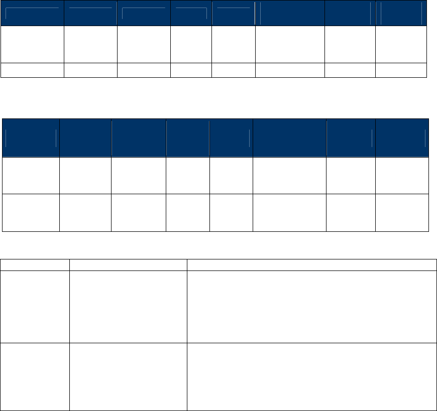
NEO Interface Developers Guide
315
Get PMC Status (F0-01)
This command is used to Get Power Management status.
Note: VP4880, VP4880E, and VP4880C do not support this command.
Command Frame
Byte 0-9 Byte 10 Byte 11 Byte 12
Byte 13
Byte 14 …
Byte 14+n-1
Byte
14+n
Byte
15+n
Header Tag
& Protocol
Version
Command
Sub-
Command
Data
Length
(MSB)
Data
Length
(LSB)
Data CRC
(LSB)
CRC
(MSB)
ViVOtech2\0
F0h 01h 00h 00h
Response Frame
Byte 0-9 Byte 10 Byte 11 Byte 12
Byte 13
Byte 14 …
Byte 14+n-1 Byte 14+n
Byte 15+n
Header Tag
& Protocol
Version
Command
Status Code
Data
Length
(MSB)
Data
Length
(LSB)
Data CRC
(MSB)
CRC
(LSB)
ViVOtech2\
0 F0h
See
Status
Code
Table
Response Data
Command Data
Data Field Length (bytes) Description/Example
Idle Time 1 Idle Time (default: 05h)
00h = Power Management turn off
01h ~ FFh= on, reader would go to sleep in 01h ~ FFh
second
Sleep Time 1
Sleep Time (default: 14h)
00h = do not stay in Low Power Mode, go to Power Off
Mode directly
01h ~ FFh = stay in Low Power Mode and go to Power Off
Mode in 01h ~ FFh second
Get Battery Level (F0-02)
This command is used to battery level.
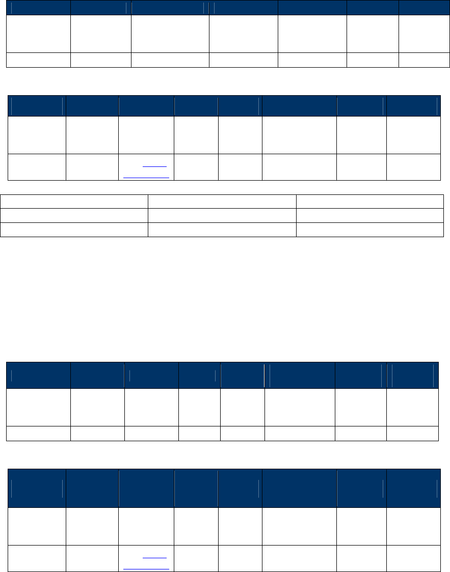
NEO Interface Developers Guide
316
Note: VP4880, VP4880E, and VP4880C do not support this command.
Command Frame
Byte 0-9 Byte 10 Byte 11 Byte 12 Byte 13 Byte 14 Byte 15
Header Tag
& Protocol
Version
Command Sub-Command
Data Length
(MSB)
Data Length
(LSB)
CRC
(LSB)
CRC
(MSB)
ViVOtech2\0
F0h 02h 00h 00h
Response Frame
Byte 0-9 Byte 10 Byte 11 Byte 12
Byte 13
Byte 14 Byte 15 Byte 16
Header Tag
& Protocol
Version
Command
Status Code
Data
Length
(MSB)
Data
Length
(LSB)
Data CRC
(MSB)
CRC
(LSB)
ViVOtech2\
0 F0h See Status
Code Table
00h 01h Level
Level
content
>= 0xD2
Battery power full
<= 0xC0
Battery power low
Shut Off the Power (F0-0F)
This command is used to shut off the power.
Note: VP4880, VP4880E, and VP4880C do not support this command.
Command Frame
Byte 0-9 Byte 10 Byte 11 Byte 12
Byte 13
Byte 14 …
Byte 14+n-1
Byte
14+n
Byte
15+n
Header Tag
& Protocol
Version
Command
Sub-
Command
Data
Length
(MSB)
Data
Length
(LSB)
Data CRC
(LSB)
CRC
(MSB)
ViVOtech2\0
F0h 0Fh 00h 00h
Response Frame
Byte 0-9 Byte 10 Byte 11 Byte 12
Byte 13
Byte 14 …
Byte 14+n-1 Byte 14+n
Byte 15+n
Header Tag
& Protocol
Version
Command
Status Code
Data
Length
(MSB)
Data
Length
(LSB)
Data CRC
(MSB)
CRC
(LSB)
ViVOtech2\
0 F0h See Status
Code Table
00h 00h
NEO Interface Developers Guide
317

NEO Interface Developers Guide
318
14.0 ViVOpay Vendi reader Commands
Configure Buttons (F0-F4)
This command configures the buttons on the ViVOpay Vendi reader. Both the SWIPE and DONE
buttons can be independently disabled with this command. This command also sets the TAP
disable time for when the SWIPE button is pressed. When the SWIPE button is enabled, the
contactless reader is turned off for the programmed delay time so that a false read does not
occur when the user wishes to swipe a dual contactless/MagStripe card.
Command Frame
Byte 0-9
Byte 10
Byte 11
Byte 12
Byte 13
Byte 14 to 16
Byte 17
Byte 18
Header Tag
& Protocol
Version
Command
Sub-
Command
Data
Length
(MSB)
Data
Length
(LSB)
Data CRC
(LSB)
CRC
(MSB)
ViVOtech2\0
F0h
F4h
00h
03h
Done
Swipe
Delay
If Done (Byte 14) is set to 01h, the Done switch is enabled. If Done (Byte 14) is set to 00h, the
DONE switch is disabled. When the DONE button is pressed, the byte string: “02 02 5B 2F” is
sent to the serial port (5B 2F are the 2 CRC bytes). Pressing the DONE button also displays
“DONE” on the LCD display.
If Swipe (Byte 15) is set to 01h, the Swipe Card switch is enabled. If Swipe (Byte 15) is set to 00h
the Swipe Card switch is disabled. The Swipe Card button sends the 4 bytes “02 03 4B 0E” to
the serial port (4B 0E are the 2 CRC bytes). The Vendi can be configured to disable the
contactless reader for a specified number of seconds. The only visual indication is that the LCD
flashes when it writes “Please swipe card” on the LCD and then immediately rewrites the
default message.
The Delay is an unsigned delay value in seconds. This should probably not be set to values larger
than 30 seconds (Byte 16).
Response Frame
Byte 0-9
Byte 10
Byte 11
Byte 12
Byte 13
Byte 14
Byte 15
Header Tag &
Protocol
Version
Command Status Code
Data
Length
(MSB)
Data
Length
(LSB)
CRC (MSB) CRC (LSB)
ViVOtech2\0 F0h
See Status
Code Table
00h 00h
The reader switches configuration only if the Response Frame contains an OK Status Code. No
data is returned in the response.
Get Button Configuration (F0-F5)
This command reads the button configuration from the ViVOpay Vendi reader.
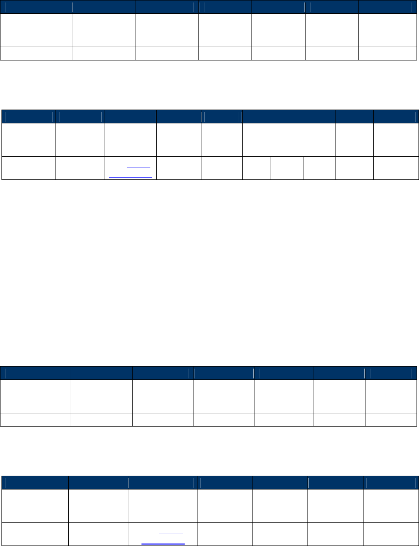
NEO Interface Developers Guide
319
Command Frame
Byte 0-9
Byte 10
Byte 11
Byte 12
Byte 13
Byte 14
Byte 15
Header Tag &
Protocol
Version
Command Sub-
Command
Data
Length
(MSB)
Data
Length
(LSB)
CRC (LSB)
CRC (MSB)
ViVOtech2\0
F0h
F5h
00h
00h
Response Frame
Byte 0-9
Byte 10
Byte 11
Byte 12
Byte 13
Byte 14 to 16
Byte 17
Byte 18
Header Tag
& Protocol
Version
Command
Status
Code
Data
Length
(MSB)
Data
Length
(LSB)
Data CRC
(MSB)
CRC
(LSB)
ViVOtech2\
0 F0h
See Status
Code Table
00h 03h
Done
Swipe
Delay
Swipe
Delay
Done is a Boolean value; if it is set to 0 the DONE switch is disabled.
Swipe is a Boolean value; if it is set to 0 the SWIPE CARD switch is disabled.
Delay is an unsigned 8 bit delay value in seconds.
Disable Blue LED Sequence (F0-F6)
This command stops the blue LEDs on the ViVOpay Vendi reader from flashing in left to right
sequence and turns the LEDs off, and contactless function is disable at the same time.
Command Frame
Byte 0-9
Byte 10
Byte 11
Byte 12
Byte 13
Byte 14
Byte 15
Header Tag &
Protocol
Version
Command Sub-
Command
Data Length
(MSB)
Data Length
(LSB) CRC (LSB)
CRC (MSB)
ViVOtech2\0
F0h
F6h
00h
00h
Response Frame
Byte 0-9
Byte 10
Byte 11
Byte 12
Byte 13
Byte 14
Byte 15
Header Tag &
Protocol
Version
Command Status Code Data Length
(MSB)
Data Length
(LSB) CRC (MSB)
CRC
(LSB)
ViVOtech2\0 F0h
See Status
Code Table
00h 00h
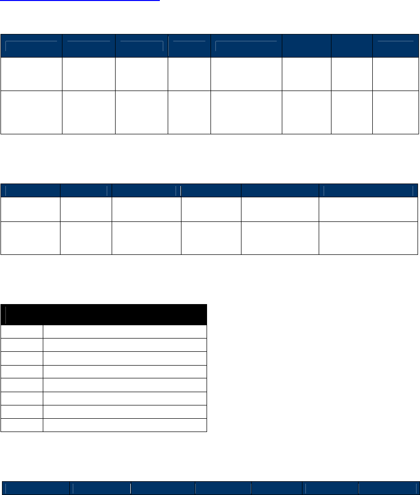
NEO Interface Developers Guide
320
Enable Blue LED Sequence (F0-F7)
Use this command to control the blue LED behavior on the Vendi reader. If you send this
command with a Data Length 00h, the reader begins a continuous LED sequence and contactless
function is enable. To customize the LED behavior, you can define a sequence of up to eight LED
behaviors, but contactless function would keep disable if F0-F6 CMD has been issue. Custom LED
behavior can also be set for a continuous cycle. To exit a continuous LED sequence, send a
Disable Blue LED Sequence Command to the reader.
Command Frame
Byte 0-9 Byte 10 Byte 11 Byte 12
Byte 13
Byte 14-n
Byte
n+1
Byte n+2
Header Tag
& Protocol
Version
Command
Sub-
Command
Data
Length
(MSB)
Data Length
(LSB)
Sequence
Data CRC
(LSB)
CRC
(MSB)
ViVOtech2\0
F0h F7h 00h
00h=continuous
sequence
04h to
19h=custom
4 to 25
bytes, if
present
Sequence Data
Byte 0
Byte 1
Byte 2-3
Byte 4
Byte 5-6
Byte 7 – 24
Cycles LEDs Duration LED Duration Additional
LED/Durations
0 = Cycle
once
1 = Repeat
LED State
Bitmap
Given in
multiples of 10
millisecond
LED State
Bitmap
Given in
multiples of 10
millisecond
You can define up to 8
LED and duration
pairs.
LED State Bitmap
Bit Description
8
Left blue LED, 0 = off, 1 = on
7
Center Blue LED, 0 = off, 1 = on
6
Right Blue LED0 = off, 1 = on
5
Yellow LED, 0 = off, 1 = on
4
Reserved for future use
3
Reserved for future use
2
Reserved for future use
1
Reserved for future use
Response Frame
Byte 0-9
Byte 10
Byte 11
Byte 12
Byte 13
Byte 14
Byte 15
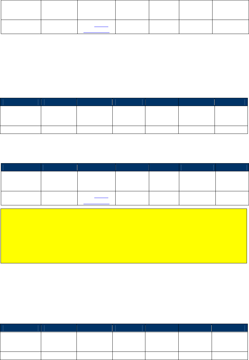
NEO Interface Developers Guide
321
Header Tag &
Protocol
Version
Command Status Code Data Length
(MSB)
Data
Length
(LSB)
CRC (MSB)
CRC (LSB)
ViVOtech2\0 F0h
See Status
Code Table
00h 00h
LCD Display Clear (F0-F9)
This command clears the LCD display.
Command Frame
Byte 0-9
Byte 10
Byte 11
Byte 12
Byte 13
Byte 14
Byte 15
Header Tag &
Protocol
Version
Command Sub-
Command
Data
Length
(MSB)
Data
Length
(LSB)
CRC (LSB) CRC (MSB)
ViVOtech2\0
F0h
F9h
00h
00h
Response Frame
Byte 0-9
Byte 10
Byte 11
Byte 12
Byte 13
Byte 14
Byte 15
Header Tag &
Protocol
Version
Command Status Code Data Length
(MSB)
Data
Length
(LSB)
CRC (MSB) CRC (LSB)
ViVOtech2\0 F0h
See Status
Code Table
00h 00h
Note: Issuing this command disables LCD management by the reader. To resume LCD
management by the reader, send a Set Configuration (‘04 00’) with a UI Scheme (tag ‘FF F8’)
with value chosen at integration. However, firmware control of the LCD does not initiate
until after a transaction event. Therefore any UI messaging linked to the initiation of a
transaction (i.e. prompt for presentation or amount display) must be written to the LCD
before issuing an Activate Transaction. At the same time, to read LCD source and get
“Internal “ after issuing LCD Display Clear(F0-F9), this feature implemented on the Vendi
follows.
Turn Off Yellow LED (F0-FA)
This command turns off the ViVOpay Vendi reader yellow LED. This LED is located below the
three blue LEDs.
Command Frame
Byte 0-9
Byte 10
Byte 11
Byte 12
Byte 13
Byte 14
Byte 15
Header Tag &
Protocol
Version
Command Sub-
Command
Data
Length
(MSB)
Data
Length
(LSB)
CRC (LSB) CRC (MSB)
ViVOtech2\0
F0h
FAh
00h
00h
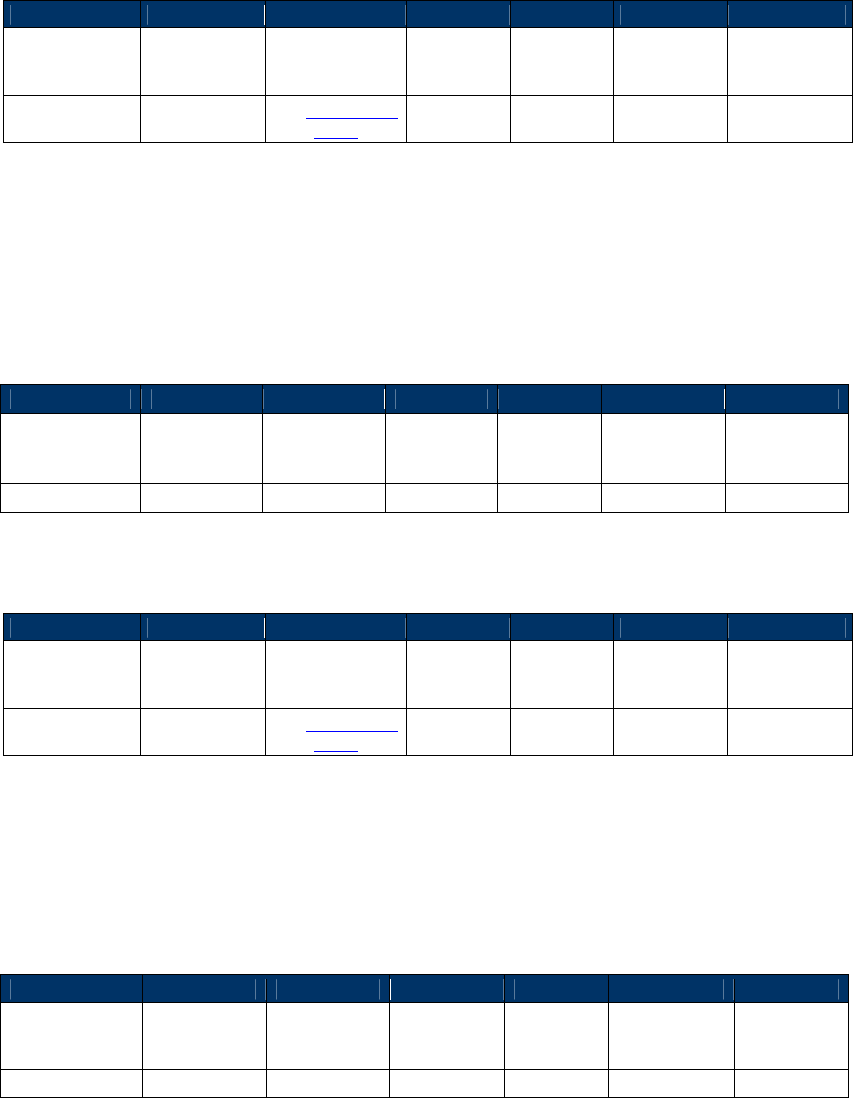
NEO Interface Developers Guide
322
Response Frame
Byte 0-9
Byte 10
Byte 11
Byte 12
Byte 13
Byte 14
Byte 15
Header Tag &
Protocol
Version
Command Status Code
Data
Length
(MSB)
Data
Length
(LSB)
CRC (MSB)
CRC (LSB)
ViVOtech2\0 F0h
See Status Code
Table 00h 00h
Turn On Yellow LED (F0-FB)
This command turns on the ViVOpay Vendi reader yellow LED. This LED is located below the
three blue LEDs.
Command Frame
Byte 0-9
Byte 10
Byte 11
Byte 12
Byte 13
Byte 14
Byte 15
Header Tag &
Protocol
Version
Command Sub-
Command
Data
Length
(MSB)
Data
Length
(LSB)
CRC (LSB) CRC (MSB)
ViVOtech2\0
F0h
FBh
00h
00h
Response Frame
Byte 0-9
Byte 10
Byte 11
Byte 12
Byte 13
Byte 14
Byte 15
Header Tag &
Protocol
Version
Command Status Code
Data
Length
(MSB)
Data
Length
(LSB)
CRC (MSB)
CRC (LSB)
ViVOtech2\0 F0h
See Status Code
Table 00h 00h
Buzzer On/Off (F0-FE)
This command causes the buzzer to beep once.
Command Frame
Byte 0-9
Byte 10
Byte 11
Byte 12
Byte 13
Byte 14
Byte 15
Header Tag &
Protocol
Version
Command Sub-
Command
Data
Length
(MSB)
Data
Length
(LSB)
CRC (LSB) CRC (MSB)
ViVOtech2\0
F0h
FEh
00h
00h
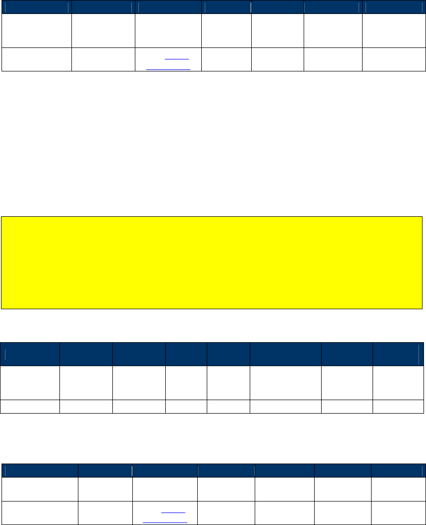
NEO Interface Developers Guide
323
Response Frame
Byte 0-9
Byte 10
Byte 11
Byte 12
Byte 13
Byte 14
Byte 15
Header Tag &
Protocol
Version
Command Status Code
Data
Length
(MSB)
Data
Length
(LSB)
CRC (MSB) CRC (LSB)
ViVOtech2\0 F0h
See Status
Code Table
00h 00h
LCD Display Line 1 Message (F0-FC)
Use this command to display text on the LCD display. On the Vendi reader the LCD is a 2-line
character display. Valid messages for the first line of text are between 1 and 16 printable
characters long. If the text message is greater than 16 bytes but not more than 32 bytes, byte
17 and onward are displayed as a second row of text. Messages with more than 32 bytes are
rejected with an unknown subcommand status code. All messages are left justified on the LCD
display.
Note: Issuing this command disables LCD management by the reader. To resume UI
management by the reader, send a Set Configuration (‘04 00’) with a UI Scheme (tag ‘FF F8’)
with value chosen at integration. However, firmware control of the LCD does not initiate
until after a transaction event. Therefore any LCD messaging linked to the initiation of a
transaction (i.e. prompt for presentation or amount display) must be written to the LCD
before issuing an Activate Transaction. At the same time, to read LCD source and get
“Internal “ after issuing LCD DisplayLine 1 Message (F0-FC), this feature implemented on the
Vend, and Vendi follows.
Command Frame
Byte 0-9 Byte 10 Byte 11 Byte 12
Byte 13
Byte 14 -
(Byte 14+n-1_
Byte
(14+n)
Byte
(14+n +1)
Header Tag
& Protocol
Version
Command
Sub-
Command
Data
Length
(MSB)
Data
Length
(LSB)
Data CRC (LSB)
CRC (MSB)
ViVOtech2\0
F0h
FCh
00h
Msg len
LCD message
Response Frame
Byte 0-9
Byte 10
Byte 11
Byte 12
Byte 13
Byte 14
Byte 15
Header Tag &
Protocol Version
Command
Status Code
Data Length
(MSB)
Data Length
(LSB)
CRC (MSB)
CRC (LSB)
ViVOtech2\0 F0h
See Status
Code Table 00h 00h
LCD Display Line 2 Message (F0-FD)
This command displays the command’s message on line 2 of the LCD display. On the Vendi
reader the LCD is a 2-line character display. Valid messages are between 1 and 16 printable
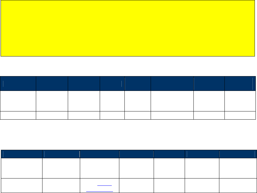
NEO Interface Developers Guide
324
characters long. Any message that is longer than 16 bytes is rejected with an unknown
subcommand status code. All messages are left justified on the LCD display.
Note: Issuing this command disables LCD management by the reader. To resume LCD
management by the reader, send a Set Configuration (‘04 00’) with a UI Scheme (tag ‘FF F8’)
with value chosen at integration. However, firmware control of the LCD does not initiate
until after a transaction event. Therefore any UI messaging linked to the initiation of a
transaction (i.e. prompt for presentation or amount display) must be written to the LCD
before issuing an Activate Transaction. At the same time, to read LCD source and get
“Internal “ after issuing LCD Display Line 2 Message (F0-FD), this feature implemented on the
Vend, and Vendi follows.
Command Frame
Byte 0-9 Byte 10 Byte 11 Byte 12
Byte 13
Byte 14 +n
Byte
14+n+1
Byte
15+n=2
Header Tag
& Protocol
Version
Command
Sub-
Command
Data
Length
(MSB)
Data
Length
(LSB)
Data CRC (LSB)
CRC (MSB)
ViVOtech2\0
F0h
FDh
00h
Msg len
LCD message
Response Frame
Byte 0-9
Byte 10
Byte 11
Byte 12
Byte 13
Byte 14
Byte 15
Header Tag &
Protocol
Version
Command Status Code Data Length
(MSB)
Data
Length
(LSB)
CRC (MSB)
CRC (LSB)
ViVOtech2\0 F0h
See Status
Code Table 00h 00h

NEO Interface Developers Guide
325
15.0 ApplePay VAS, SmartTap2.1 and Other Special
Functions
ApplePay VAS Functionality
NEO firmware has built-in support for Apple Value Added Services Protocol (hereinafter called
Apple VAS). For detailed information on how Apple VAS works, consult Apple's developer site at
https://developer.apple.com/library/content/documentation/UserExperience/Conceptual/Pass
Kit_PG/index.html#//apple_ref/doc/uid/TP40012195-CH1-SW1. The following discussion
assumes that you are familiar with the basic concepts behind ApplePay VAS.
Overview
In order to process an ApplePay VAS transaction, the terminal’s merchant records must first be
set. This should be done using TLVs sent in the Set Merchant Record (04-11) command (discussed
further below).
A Merchant ID (of the form "Pass.com.apple.wallet.vas.prodtest") is generally associated with a
hash value and (optionally) a URL. The hash is just a SHA-256 hash of the Merchant ID string
itself. For example, the Merchant ID “pass.com.apple.wallet.vas.prodtest,” in hex, is
represented as 70 61 73 73 2e 63 6f 6d 2e 61 70 70 6c 65 2e 77 61 6c 6c 65 74 2e 76 61 73 2e 70
72 6f 64 74 65 73 74. (Spaces are inserted for clarity.) When a byte array containing those values
is hashed, the resulting SHA-256 value is 3C C7 0E D8 9A 9D 43 54 BE 98 30 AB 58 D8 9C 6F E7 E6
2B AC A9 39 D2 A6 85 1D FC 60 2E A7 98 F7.
Limitations
Note that a NEO device can store at most 6 Merchant Records for Apple VAS. This means the
device can natively support up to 6 loyalty programs (per transaction) at a time.
Note to Developers
If you are sending commands via the “Send NEO Command” in the Universal Demo, or using
device_sendDataCommand() in the SDK, only the command, subcommand, and data fields need
to be sent. The header, data length, and CRC will be dynamically calculated and inserted into
the command string, automatically, by the SDK.
ACT Parameters for ApplePay VAS
The Activate Transaction (ACT) parameters required for the ApplePay VAS functionality are
communicated via the ApplePay VAS Container TLV (tag FFEE06). The FFEE06 TLV must be
provided in the ACT command (02-01 or 02-40) if an ApplePay VAS transaction is desired.

NEO Interface Developers Guide
326
Tag 9F26 ApplePay Terminal Capabilities Information
Byte 1: Format
b8
b7
b6
b5
b4
b3
b2
b1
Description
x
x
x
x
x
x
x
x
RFU, Bits b8-b1 shall be set to 0
Byte 2: Terminal Type
b8
b7
b6
b5
b4
b3
b2
b1
Description
0
-
-
-
-
-
-
-
VAS Supported
1
-
-
-
-
-
-
-
VAS Not Supported
-
0
-
-
-
-
-
-
Touch ID Required
-
1
-
-
-
-
-
-
Touch ID not Required
-
-
-
-
0
0
0
0
Payment Terminal
-
-
-
-
0
0
0
1
Transit Terminal
-
-
-
-
0
0
1
0
Access Terminal
-
-
-
-
0
0
1
1
Wireless handoff Terminal
-
-
-
-
0
1
0
0
App Handoff Terminal
-
-
-
-
1
1
1
1
Other Terminal
-
-
-
-
-
-
-
-
All other values are RFU
TLV
Name
Presence
Description
9F26
ApplePay Terminal
Capabilities Information (see
table below for more
information)
Rqrd
Determines how the reader handles
the VAS and/or Payment flow.
This data comprises 4 Bytes.
Byte 1: RFU
Byte 2: Terminal Type
Byte 3: RFU
Byte 4: Terminal Mode
See table further below.
9F22
ApplePay Terminal
Application Version Number
Rqrd
Hard-defined as 01.00 for now.
9F2B
ApplePay VAS Filter
Opt
If not provided filtering will not be
performed by the mobile.
DF01
ApplePay VAS Protocol
87654321
-------0 URL VAS
Protocol
-------1 FULL VAS
Protocol
------0- No VAS Beeps
------1- VAS Beeps
-----0-- EMEA Comm
Error
-----1-- Silent Comm
Error
Opt
If not provided the following settings
are used by default:
Full VAS protocol
No beeps for VAS
EMEA Communications Error
Handling
If provided the bits define the
settings.

NEO Interface Developers Guide
327
Byte 3: RFU
b8
b7
b6
b5
b4
b3
b2
b1
Description
x
x
x
x
x
x
x
x
RFU, Bits b8-b1 shall be set to 0
Byte 4: Terminal Mode
b8
b7
b6
b5
b4
b3
b2
b1
Description
x
x
x
x
x
x
x
x
Terninal in VAS App OR Payment Mode
Terminal in VAS App AND Payment Mode
Terminal in VAS App Only Mode
Terminal in Payment Mode Only
Bits b8-b3 shall be set to 0
All other values are RFU
Byte 4: Terminal Mode polling Loop
ApplePay Terminal
Capabilities Information
Card Filter Settings
00
PICC_POLL_TYPE_APPLE_VAS_OR_PAY,
PICC_POLL_TYPE_A and
PICC_POLL_TYPE_B
01
PICC_POLL_TYPE_APPLE_VAS_AND_PAY,
PICC_POLL_TYPE_A and
PICC_POLL_TYPE_B
10
PICC_POLL_TYPE_APPLE_VAS_ONLY,
PICC_POLL_TYPE_A and
PICC_POLL_TYPE_B
11
PICC_POLL_TYPE_APPLE_PAY_ONLY,
PICC_POLL_TYPE_A and
PICC_POLL_TYPE_B
EXAMPLES (Activate Transaction Command Examples for ApplePay VAS)
Command sent using the SDK (VAS-only transaction):
dtVendi.ctls_startTransaction(10,0,0,60,Common.getByteArray("FFEE06189F22020100
9F2604000000039F2B050100000000DF010101"));
Using firmware commands:
Note: Some firmware examples use command 02-01, but 02-40 (encryption-enabled Activate
Transaction) may also be used.
VAS Only Activate Transaction (02-40)
56 69 56 4F 74 65 63 68 32 00 02 40 00 29 30 9F 02 06 00 00 00 00 00 01 9C 01 00 FF EE 06 18 9F
22 02 01 00 9F 26 04 00 00 00 02 9F 2B 05 01 00 00 00 00 DF 01 01 01 33 FE
Command Sent Breakdown:
56 69 56 4F 74 65 63 68 32 00 – ViVOTech2 header
02 40 – Start transaction command
00 29 – Data Length
30 – Time out
9F 02 06 00 00 00 00 00 01 – Transaction amount
NEO Interface Developers Guide
328
9C 01 00 – Transaction Type
FF EE 06 – ApplePay VAS Collective
18 - length of ApplePay VAS collective
9F 22 02 01 00 - ApplePay Terminal AVN
9F 26 04 00 00 00 02 - ApplePay terminal Capabilities - 02 = VAS only
9F 2B 05 01 00 00 00 00 - AppplePay VAS Filter (optional)
DF 01 01 01 –
33 FE – CRC-16
Vendi Response:
56 69 56 4F 74 65 63 68 32 00 02 57 00 FF D1 FF EE 12 0A 62 99 49 01 2C 00 04
60 01 AC FF EE 06 82 00 D9 9A 03 14 08 15 9F 21 03 17 32 53 9F 25 20 3C C7 0E
D8 9A 9D 43 54 BE 98 30 AB 58 D8 9C 6F E7 E6 2B AC A9 39 D2 A6 85 1D FC 60 2E
A7 98 F7 9F 2A 00 9F 27 3E 93 1C 1A 60 4A 46 09 9E 21 EC 88 6D EF CC 8C B8 8B
CA 03 CC 4B C6 62 0C C1 8F 8C 10 5A 7A F1 4F 9B 3C D9 E3 36 4E 9C 8C BF E0 90
34 10 B1 58 3C 3D 63 AC 9F CC 48 9C A8 76 AE 8C B3 E5 62 9F 25 20 3C C7 0E D8
9A 9D 43 54 BE 98 30 AB 58 D8 9C 6F E7 E6 2B AC A9 39 D2 A6 85 1D FC 60 2E A7
98 F7 9F 2A 00 9F 27 3E 93 1C 1A 60 4A 46 09 9E 21 EC 88 6D EF CC 8C B8 8B CA
03 CC 4B C6 62 0C C1 8F 8C 10 5A 7A F1 4F 9B 3C D9 E3 36 4E 9C 8C BF E0 90 34
10 B1 58 3C 3D 63 AC 9F CC 48 9C A8 76 AE 8C B3 E5 62 9F 39 01 07 FF EE 01 04
DF 30 01 00 DF EE 26 01 D1 ED CA
Vendi Response Breakdown:
56 69 56 4F 74 65 63 68 32 00 – ViVOTech2 header
02 – Act Command returned
57 – Status. 57 = no payment occurred
00 FF – Data length
D1 – Attribution byte
FF EE 12 0A 62 99 49 01 2C 00 04 60 01 12 - KSN tag (FFEE12), length
0x0A, KSN bytes. Transaction is encrypted.
FF EE 06 - Apple Pay Vas container
00 82 - Data length
D9 9A 03 14 08 15 9F 21 03 17 32 53 9F 25 20 3C C7 0E D8 9A 9D 43 54 BE
98 30 AB 58 D8 9C 6F E7 E6 2B AC A9 39 D2 A6 85 1D FC 60 2E A7 98 F7 9F
2A 00 9F 27 3E 93 1C 1A 60 4A 46 09 9E 21 EC 88 6D EF CC 8C B8 8B CA 03
CC 4B C6 62 0C C1 8F 8C 10 5A 7A F1 4F 9B 3C D9 E3 36 4E 9C 8C BF E0 90
34 10 B1 58 3C 3D 63 AC 9F CC 48 9C A8 76 AE 8C B3 E5 62 9F 25 20 3C C7
0E D8 9A 9D 43 54 BE 98 30 AB 58 D8 9C 6F E7 E6 2B AC A9 39 D2 A6 85 1D
FC 60 2E A7 98 F7 9F 2A 00 9F 27 3E 93 1C 1A 60 4A 46 09 9E 21 EC 88 6D
EF CC 8C B8 8B CA 03 CC 4B C6 62 0C C1 8F 8C 10 5A 7A F1 4F 9B 3C D9 E3
36 4E 9C 8C BF E0 90 34 10 B1 58 3C 3D 63 AC 9F CC 48 9C A8 76 AE 8C B3
E5 62 9F 39 01 07 FF EE 01 04 DF 30 01 00 DF EE 26 01 D1 –
ED CA – CRC
NEO Interface Developers Guide
329
VAS Or Pay Activate Transaction (02-01)
56 69 56 4F 74 65 63 68 32 00 02 01 00 29 30 9F 02 06 00 00 00 00 00 01 9C 01 00 FF EE 06 18 9F
22 02 01 00 9F 26 04 00 00 00 00 9F 2B 05 01 00 00 00 00 DF 01 01 01 09 CA
VAS And Pay Activate Transaction (02-01)
56 69 56 4F 74 65 63 68 32 00 02 01 00 29 30 9F 02 06 00 00 00 00 00 01 9C 01 00 FF EE 06 18 9F
22 02 01 00 9F 26 04 00 00 00 01 9F 2B 05 01 00 00 00 00 DF 01 01 01 6A 8F
VAS Only Activate Transaction (02-01)
56 69 56 4F 74 65 63 68 32 00 02 01 00 29 30 9F 02 06 00 00 00 00 00 01 9C 01 00 FF EE 06 18 9F
22 02 01 00 9F 26 04 00 00 00 02 9F 2B 05 01 00 00 00 00 DF 01 01 01 CF 40
Pay Only Activate Transaction (02-01)
56 69 56 4F 74 65 63 68 32 00 02 01 00 29 30 9F 02 06 00 00 00 00 00 01 9C 01 00 FF EE 06 18 9F
22 02 01 00 9F 26 04 00 00 00 03 9F 2B 05 01 00 00 00 00 DF 01 01 01 AC 05
Transaction Responses
Both the ApplePay VAS response and the normal payment transaction response will be
provided in a single returned data record. Whether returned in response to a blocking ACT
or a non-blocking ACT, it will be the same. As described above, there are ApplePay VAS
scenarios where either the VAS transaction or the payment transaction may not be
performed. In those scenarios you will only see the results of the transaction that was
actually performed. Only when both VAS and payment transactions are performed will you
see both transaction responses in the same returned data record.
The Payment transaction response will not change. The VAS transaction response will be
embedded in the proprietary ApplePay VAS Container TLV (0xFFEE06). Each Merchant ID and
its associated data will be shown in sequence.
Transaction Response for Combined Payment and VAS
56 69 56 4F 74 65 63 68 32 00 – Serial Command header
02 – Command
23 – Status – for the payment transaction only. In this example it indicates a Request for
Online Authorization
nn nn – length of entire response (VAS and Pay)
xx - Start of payment response. Payment response format has not changed.
xx – End of payment response.
FFEE06 nn - ApplePay VAS Container
9A nn – Date
9F21 nn - Time
9F25 nn – Merchant ID a
9F2A nn – Mobile Token
9F27 nn – VAS Data
9F25 nn – Merchant ID b
9F2A nn – Mobile Token
9F27 nn – VAS Data
. . .
9F25 nn – Merchant ID n
9F2A nn – Mobile Token
9F27 nn – VAS Data
xx xx – CRC for entire response
NEO Interface Developers Guide
330
Transaction Response for VAS Only (No Payment)
56 69 56 4F 74 65 63 68 32 00 – Serial Command header
02 – Command
57 – Status for the payment transaction. 0x57 indicates there was no payment transaction.
nn nn – length of entire response (VAS)
FFEE06 nn - ApplePay VAS ContainerViVOpay
9A nn – Date
9F21 nn - Time
9F25 nn – Merchant ID a
9F2A nn – Mobile Token
9F27 nn – VAS Data
9F25 nn – Merchant ID b
9F2A nn – Mobile Token
9F27 nn – VAS Data
. . .
9F25 nn – Merchant ID n
9F2A nn – Mobile Token
9F27 nn – VAS Data
xx xx – CRC for entire response
Transaction Response for VAS VAS Failure in Select
56 69 56 4F 74 65 63 68 32 00 – Serial Command header
02 – Command
57 – Status for the payment transaction. 0x57 indicates there was no payment transaction.
nn nn – length of entire response (VAS)
FFEE06 nn - ApplePay VAS ContainerViVOpay
9A nn – Date
9F21 nn - Time
DF02 nn – ApplePay VAS Failure Report
xx xx – CRC for entire response
ApplePay VAS Failure Report
DF0204206A8002
DF02 - ApplePay VAS Failure Report Tag
04 – Length of ApplePay VAS Failure Report
20 = Error Code, See IDG for Error Code Encoding
6A80 – SW1-SW2 Status from last APDU received
02 – RF State failure occurred in. 02 = Select
Transaction Response for VAS Failure in Get Data
56 69 56 4F 74 65 63 68 32 00 – Serial Command header
02 – Command
57 – Status for the payment transaction. 0x57 indicates there was no payment transaction.
nn nn – length of entire response (VAS)
FFEE06 nn - ApplePay VAS ContainerViVOpay
9A nn – Date
9F21 nn - Time
9F25 nn – Merchant ID a
DF02 nn – ApplePay VAS Failure Report for Merchant ID a
9F25 nn – Merchant ID b
9F2A nn – Mobile Token
9F27 nn – VAS Data
. . .
9F25 nn – Merchant ID n
9F2A nn – Mobile Token
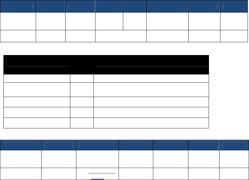
NEO Interface Developers Guide
331
9F27 nn – VAS Data
xx xx – CRC for entire response
Set Merchant Record (04-11)
Command Frame
Byte 0-9 Byte 10 Byte 11 Byte 12 Byte 13
Byte 14 …
Byte 14+n-1 Byte 14+n
Byte15+n
Header Tag
& Protocol
Version
Command
Sub-
Command
Data
length
(MSB)
Data
length
(LSB)
Data CRC
(MSB)
CRC
(LSB)
ViVOtech2\0
04 11h 63h
See Data
Format below
Data Field for Command Frame
Data Field Length
(bytes)
Description
Merchant Record Index
1
The valid value is 1--6.
ID Present
1
1: The Merchant ID is valid,
0: The Merchant ID is not valid.
Merchant ID
32
The tag is 9F25.
Length of Merchant URL
1
Can be zero, if no URL is used.
Merchant URL (optional)
64
The tag is 9F29.
Response Frame
Byte 0-9 Byte 10 Byte 11 Byte 12 Byte 13 Byte 14 Byte 15
Header Tag &
Protocol
Version
Command Status Data length
(MSB)
Data length
(LSB) CRC(MSB)
CRC(LSB)
ViVOtech2\0 04h
See Status Code
Table
00 00
EXAMPLE
Set Merchant Record command using the SDK:
idtVendi.device_sendDataCommand("041101013CC70ED89A9D4354BE9830AB58D89C6FE7E62B
ACA939D2A6851DFC602EA798F700000000000000000000000000000000000000000000000000000
00000000000000000000000000000000000000000000000000000000000000000000000000000",
false,resDataStruct);
Set Merchant Record command via raw firmware commands:
56 69 56 4F 74 65 63 68 32 00 04 11 00 63 01 01 3C C7 0E D8 9A 9D 43 54 BE 98
30 AB 58 D8 9C 6F E7 E6 2B AC A9 39 D2 A6 85 1D FC 60 2E A7 98 F7 00 00 00 00
00 00 00 00 00 00 00 00 00 00 00 00 00 00 00 00 00 00 00 00 00 00 00 00 00 00
00 00 00 00 00 00 00 00 00 00 00 00 00 00 00 00 00 00 00 00 00 00 00 00 00 00
00 00 00 00 00 00 00 00 00 25 B1
Breakdown of command sent:
56 69 56 4F 74 65 63 68 32 00 – ViVOtech2\0 header

NEO Interface Developers Guide
332
04 – Set Merchant Command
11 – Set Merchant Sub-Command
00 63 – Data Length
01 - Merchant Index number
01 - Merchant ID is enabled
3C C7 0E D8 9A 9D 43 54 BE 98 30 AB 58 D8 9C 6F E7 E6 2B AC A9 39 D2 A6
85 1D FC 60 2E A7 98 F7 - Merchant ID (this is the SHA-256 hash of the
IDTech Pass having the name "pass.com.apple.wallet.vas.prodtest")
00 - Length of VAS URL. In this example, none was provided.
00 00 00 00 00 00 00 00 00 00 00 00 00 00 00 00 00 00 00 00 00 00 00 00
00 00 00 00 00 00 00 00 00 00 00 00 00 00 00 00 00 00 00 00 00 00 00 00
00 00 00 00 00 00 00 00 00 00 00 00 00 00 00 00
– URL if provided
25 B1 – CRC-16
Vendi Response:
56 69 56 4F 74 65 63 68 32 00 04 00 00 00 AE 16
Breakdown of Vendi Response:
56 69 56 4F 74 65 63 68 32 00 – ViVOtech2\0 Header
04 – Command
00 – Status (see table “Status Codes For Protocol 2“)
00 00 – data
AE 16 - CRC
Get Merchant Record (03-11)
Command Frame
Byte 0-9 Byte 10 Byte 11 Byte 12 Byte 13
Byte 14 Byte 15
Byte16
Header Tag
& Protocol
Version
Command
Sub-
Command
Data
length
(MSB)
Data
length
(LSB)
Data CRC
(MSB)
CRC
(LSB)
ViVOtech2\0
03 11h 01
Merchant Record
Index(1-6)
Response Frame
Byte 0-9 Byte 10 Byte 11 Byte 12 Byte 13
Byte 14 …
Byte 14+n-1 Byte 14+n
Byte15+n
Header Tag
& Protocol
Version
Command
Status
Data
length
(MSB)
Data
length
(LSB)
Data CRC
(MSB)
CRC
(LSB)
ViVOtech2\0
03
See Status
Code
Table
63h See Data
Format below
Data Field for Response Frame
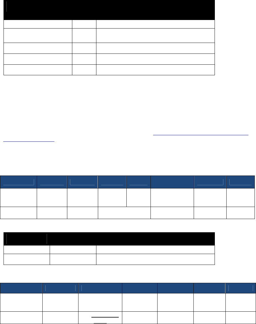
NEO Interface Developers Guide
333
Data Field Length
(bytes)
Description
Merchant Record Index
1
The valid value is 1--6.
ID Present
1
1: The Merchant ID is valid,
0: The Merchant ID is not valid.
Merchant ID
32
The tag is 9F25.
Length of Merchant URL
1
Merchant URL
64
The tag is 9F29.
Peer To Peer Functionality
The Peer To Peer functionality can only be used in Pass-Through mode. It allows the sending and
receiving of NDEF messages to/from a mobile device. See https://learn.adafruit.com/adafruit-
pn532-rfid-nfc/ndef for more information about NDEF payload composition.
Peer To Peer Send A Message (C7-9A)
Command Frame
Byte 0-9 Byte 10 Byte 11 Byte 12 Byte 13
Byte 14 …
Byte 14+n-1 Byte 14+n
Byte15+n
Header Tag
& Protocol
Version
Command
Sub-
Command
Data
length
(MSB)
Data
length
(LSB)
Data CRC
(MSB)
CRC
(LSB)
ViVOtech2\0
C7h 9Ah Variable
See Data
Format below
Peer To Peer Send A Message Data Field for Command Frame
Data Field Length (bytes) Description
Timeout
1
Time in Seconds.
Message
Variable
NDEF message to be sent to the phone
Response Frame
Byte 0-9 Byte 10 Byte 11 Byte 12 Byte 13 Byte 14 Byte 15
Header Tag &
Protocol
Version
Command Status Data length
(MSB)
Data length
(LSB) CRC(MSB)
CRC(LSB)
ViVOtech2\0 C7h
See Status Code
Table
00 00
Peer To Peer Receive A Message (C7-9B)
Command Frame

NEO Interface Developers Guide
334
Byte 0-9 Byte 10 Byte 11 Byte 12
Byte 13
Byte 14 Byte 15 Byte16
Header Tag
& Protocol
Version
Command
Sub-
Command
Data
length
(MSB)
Data
length
(LSB)
Data CRC
(MSB)
CRC
(LSB)
ViVOtech2\0
C7 9Bh 00h 01h
Timeout
(1 byte, time in
seconds)
Response Frame
Byte 0-9 Byte 10 Byte 11 Byte 12 Byte 13
Byte 14 …
Byte 14+n-1
Byte 14+n
Byte 15+n
Header Tag
& Protocol
Version
Command
Status
Data
length
(MSB)
Data
length
(LSB)
Data CRC
(MSB)
CRC
(LSB)
ViVOtech2\0
C7h See Status
Code Table
Variable
See Data
description
below
If Status code is OK, Data Field for Response Frame is a message received from the phone.
Otherwise, Data Length is zero and no data for Response Frame.
Messages conform to NDEF (https://learn.adafruit.com/adafruit-pn532-rfid-nfc/ndef).
Asynchronous Media Tracking (Only for Kiosk III)
This feature is to generate notifiation events to indicate that a card has arrived in or departed
form the RF field. Reader has the ability to send out Asynchronous Packet of card arrival or card
removal to the POS in real-time.
The Asynchronous Packet for Meida Tracking is :
07 50 [Payload] [CRC]
07 - Async MTAS Packet
50 - Status OK
[Payload] - Tag DFEF36 (3 byte Tag ID, 1 byte length, 4 data bytes)
[CRC] - 2 byte CRC
This feature can be enabled by setting the bits appropriately in the first byte of MTAS. It is done
via the Set Configuration Command (04-00), This is the only way to set this tag.
If CL media arrival reporting is enabled, reader will send out a Asynchronous Packet to the POS
to tell card arriving. This feature is supported in both Native mode and Pass Through mode.
For example: 07 50 DF EF 36 04 03 0B 00 00 CC 8F
If CL media removal reporting is enabled, reader will send out a Asynchronous Packet to the POS
to tell card removal. This feature is only supported in Native mode.
For example: 07 50 DF EF 36 04 03 11 00 00 48 2D
Send Media Status Tracking Asynchronously in Pass Through Mode
Card removal reporting is not supported in Pass Through mode,
If CL media arrival reporting bit is set, reader will send out a Asynchronous Packet when reader
detects a card during Poll for Token command (standard or enhanced).

NEO Interface Developers Guide
335
Send Media Status Tracking Asynchronously in Native Mode
If any the control bits for this TLV are set, then this TLV will be sent back to the POS
asynchronously during a transaction.
If more than one control bit were set, then its probable that the TLV will be returned multiple
times during a single transaction. For exmaple, the reader might return the TLV when a
contactless card is detected, and then later return the TLV again when the remval of the
contactless card takes place.
Send Media Status Tracking Asynchronously in Auto Switch
If Auto Switch is enabled and reader goes into Auto Switch mode, reader will only report card
arrival, and when Auto Switch happen, reader gets into Pass Through mode, so card removal
won't be reproted.
Determine Card Presence (Only for Kiosk III)
This feature is only supported in Native Mode.
This feature is not designed to collect any card data at all, and won't detect card is in the field
between transactions. It is simply detect the status of the RF.
This feature is implemented by Detect Card Presence Command
Detect Card Presence Command (02-05)
Command Frame
Byte 0-9
Byte 10
Byte 11
Byte 12
Byte 13
Byte 14
Byte 15
Byte 16
Header Tag
& Protocol
Version
Command
Sub-
Command
Data
Length
(MSB)
Data
Length
(LSB)
Data CRC
(LSB)
CRC
(MSB)
ViVOtech2\0
02h
05h
00
01
Timeout
Data Item Length
(bytes) Description
Timeout
1
Time in seconds that the reader waits for a card to be presented
before timing out and returning an Error response. The reader will
continue to poll for this amount of time if no card is found. Format:
Binary

NEO Interface Developers Guide
336
Response Frame
Byte 0-9 Byte 10 Byte 11 Byte 12
Byte 13
Byte 14 …
Byte 14+n-1 Byte 14+n
Byte 15+n
Header Tag
& Protocol
Version
Command
Status Code
Data
Length
(MSB)
Data
Length
(LSB)
Data CRC
(MSB)
CRC
(LSB)
ViVOtech2\0
02h
See Status
Code Table
If a card presence is detected by this command, the "Data" field will be the MTAS data(Tag
DFEF36 (3 byte Tag ID, 1 byte length, 4 data bytes))
If no card presence is detect by this command, then reader will response timeout.
MSR Equivalent Data Function
Proprietary tags DFEF4B, DFEF4C, and DFEF4D provide a way for track data (and optionally, PAN
data) to be supplied in conjunction with an EMV transaction, with or without sentinels, in a form
similar to the form track data would take in a conventional MSR transaction.
DFEF4C and DFEF4D TLV will only appear in the response of 02-40/03-40 commands for
successful transaction.
Tag DFEF4B
Tag DFEF4B is a configuration tag. Use it to tell your reader which tracks you want to receive in
tag DFEF4D, whether or not to use sentinels, and whether or not to include the PAN as a
separate string.
Byte 1:
8
7
6
5
4
3
2
1
NOTES
-
-
-
-
-
-
-
X
0 – Disable Track 3 Sentinels
1 – Enable Track 3 Sentinels
-
-
-
-
-
-
X
-
0 – Disable Track 2 Sentinels
1 – Enable Track 2 Sentinels
-
-
-
-
-
X
-
-
0 – Disable Track 1 Sentinels
1 – Enable Track 1 Sentinels
-
-
-
-
X
-
-
-
0 – Disable Track 3
1 – Enable Track 3
-
-
-
X
-
-
-
-
0 – Disable Track 2
1 – Enable Track 2
-
-
X
-
-
-
-
-
0 – Disable Track 1
1 – Enable Track 1

NEO Interface Developers Guide
337
-
X
-
-
-
-
-
-
0 – Disable PAN
1 – Enable PAN
X
-
-
-
-
-
-
-
0 – All Data Elements Found
1 – Only First Element Found
Byte 2: RFU
Byte 3: RFU
You can use the top bit of the first byte of DFEF4B to control search behavior: If the bit is ON,
all data elements requested will be provided (if they exist). If the bit is OFF, only the first
element found will be retrieved and placed in DFEF4D.
If you request multiple data items, they will be concatenated. To know the original lengths of
the items, you must retrieve and inspect Tag DFEF4C (see below).
To use tag DFEF4B, add it (as a TLV) to your terminal configuration settings.Use Set
Configuration (04-00) command to send the settings to your device as you normally would.
NOTE: If this tag does not exist in Terminal Settings, tags DFEF4C and DFEF4D will not be
generated.
The default value of this tag is 0x12 (Track 2 enabled, with Sentinels).
Data Search Order
When "Only First Element Found" (bit 8 = 1) is set in DFEF4B, Tag DFEF4D will be populated
with a single data element according to the following search order
Track 2, Tag 57 (converted to alpha numeric format)
Track 2, Tag 9F6B
Track 2, Tag 5F22
Track 1, Tag 56
Track 1, Tag 5F21
PAN, Tag 5A (converted to alpha numeric format)
Track 3, Tag 58
Track 3, Tag 5F23
Regardless of the original format, the data will be placed in the DFEF4D tag in alpha numeric
format, such that after decryption (and with padding removed) the data will look similar to:
3b343736313733393030313031303031303d31353132323031313134333837383038393f
Which means that after rendering it as ASCII, it would look like:
;4761739001010010=15122011143878089?
When "All Data Elements Found" (BIT 8), is specified in DFEF4B, Tag DFEF4D will be populated
with a single instance of each requested data element, according to the following order:
Track 1 requested (bit 6 = 1). Includes first instance of:
Tag 56 = Track 1 Equivalent
Tag 5F21 = Track 1, identical to the data coded
Track 2 requested (bit 5 = 1). Includes first instance of:
NEO Interface Developers Guide
338
Tag 57 = Track 2 Equivalent (converted to alpha numeric format)
Tag 9F6B = Track 2 Data
Tag 5F22 = Track 2, identical to the data coded
Track 3 requested (bit 4 = 1). Includes first instance of:
Tag 58 = Track 3 Equivalent
Tag 5F23 = Track 3, identical to the data coded
PAN requested (bit 7 = 1). Includes:
Tag 5A = PAN (converted to alpha numeric format)
Sentinels
For any found data element of Track1, Track2 or Track3, sentinels will be included or not
included according to the preferences set in bits 1, 2 and 3.
Compressed Numeric Elements
For any data element captured as compressed numeric, the following rules shall apply:
Padding (0xf) shall not be included
Center separators: 0xd shall be converted to 0x3d ("=")
Data shall be encoded as ASCII representation of binary data
example 0x123f = 0x313233 = "123" (ignore padding)
example 0x1234 = 0x31323334 = "1234"
example 0x123d456f = 0x3132333d343536 = "123=456"
Tag DFEF4C
If tag DFEF4B is set, tags DFEF4C will appear in transaction output.
This tag's 6-byte value provides the native lengths of tracks 1, 2, and 3, and the PAN (if
applicable). Two bytes are reserved for future use.
<Track 1 Length><Track 2 Length><Track 3 length><PAN length><RFU><RFU>
A length of 0 indicates track disabled in DFEF4B or data not available. This tag also serves as an
indicator of which data element was found first, when "Only First Element Found" is enabled in
DFEF4B.
Tag DFEF4D
If tag DFEF4B is set, tags DFEF4D will appear in transaction output.
This variable-length tag contains track and/or PAN data, encrypted. The exact contents will
vary depending on values supplied previously in DFEF4B (see above).
The track data will present track data if it is a MSD transaction, present track Equivalent data if
it is a EMV transaction.
When TDES or AES encryption have been used in conjunction with traditional DUKPT, decrypt
the data normally, using the 10-byte KSN found in tag DFEE12.

NEO Interface Developers Guide
339
SmartTap2.1 Function
ACT parameters for Smart Tap2.1
The ACT parameters required for the Smart Tap2.1 function are embedded in the Smart
Tap2.1 Container (FFEE08). The FFEE08 TLV is optional, but must be provided in the ACT if
a Smart Tap2.1 transaction is desired.
Terminal Mode:
b8
b7
b6
b5
b4
b3
b2
b1
Description
0
0
0
0
RFU
x
x
x
x
0000: Get VAS OR Payment Mode
0001: Get VAS AND Payment Mode
0010: Get VAS Only Mode
0011: Payment Mode Only
0101: Push VAS AND Payment Mode
0110: Push VAS Only Mode
1000: Secure Get VAS OR Payment Mode
1001: Secure Get VAS AND Payment Mode
1010: Secure Get VAS Only Mode
Activate Command Examples for Smart Tap2.1:
a) Get VAS or Pay Activate Transaction
56 69 56 4F 74 65 63 68 32 00 02 01 00 13 30 9F 02 06 00 00 00 00 00 01 9C 01 00 FF EE 08 02 00
00 FD A3
Where: 00 is the Terminal Mode, and 00 is the service request type.
b) Get VAS AND Pay Activate Transaction
56 69 56 4F 74 65 63 68 32 00 02 01 00 13 30 9F 02 06 00 00 00 00 00 01 9C 01 00 FF EE 08 02 01
00 CE 92
Where: 01 is the Terminal Mode, and 00 is the service request type.
c) Get VAS Only Activate Transaction:
56 69 56 4F 74 65 63 68 32 00 02 01 00 13 30 9F 02 06 00 00 00 00 00 01 9C 01 00 FF EE 08 02 02
00 9B C1
Where: 02 is the Terminal Mode, and 00 is the service request type.
d) Pay Only Activate Transaction:
56 69 56 4F 74 65 63 68 32 00 02 01 00 12 30 9F 02 06 00 00 00 00 00 01 9C 01 00 FF EE 08 01 03
74 FA
Offset
Name
Presence
Description
0
Terminal Mode
M
Determines how the reader handles
the VAS and/or Payment flow. See
below table for Terminal Mode.
1….
Data
O
NEO Interface Developers Guide
340
Where: 03 is the Terminal Mode.
e) Push VAS AND Pay Activate Transaction
56 69 56 4F 74 65 63 68 32 00 02 01 00 xx 30 9F 02 06 00 00 00 00 00 01 9C 01 00 FF EE 08 xx 05
xx xx xx xx xx xx
Where: 05 is the Terminal Mode, and xx xx xx xx is the new_service_record and service_status.
f) Push VAS Only Activate Transaction:
56 69 56 4F 74 65 63 68 32 00 02 01 00 xx 30 9F 02 06 00 00 00 00 00 01 9C 01 00 FF EE 08 xx 06
xx xx xx xx xx xx
Where: 06 is the Terminal Mode, and xx xx xx xx is the new_service_record and service_status
g) Secure Get VAS or Pay Activate Transaction
56 69 56 4F 74 65 63 68 32 00 02 01 00 13 30 9F 02 06 00 00 00 00 00 01 9C 01 00 FF EE 08 02 08
00 74 0A
Where: 08 is the Terminal Mode, and 00 is the service request type.
h) Secure Get VAS AND Pay Activate Transaction
56 69 56 4F 74 65 63 68 32 00 02 01 00 13 30 9F 02 06 00 00 00 00 00 01 9C 01 00 FF EE 08 02 09
00 47 3B
Where: 09 is the Terminal Mode, and 00 is the service request type.
i) Secure Get VAS Only Activate Transaction:
56 69 56 4F 74 65 63 68 32 00 02 01 00 13 30 9F 02 06 00 00 00 00 00 01 9C 01 00 FF EE 08 02 0A
00 12 68
Where: 0A is the Terminal Mode, and 00 is the service request type.
Transaction Responses
Both the Smart Tap2.1 VAS response and the normal payment transaction response will be
provided in a single returned data record. The VAS transaction response will be embedded
in the proprietary Smart Tap2.1 VAS Container TLV (0xFFEE08).
Transaction Response for Combined Payment and VAS
56 69 56 4F 74 65 63 68 32 00 02 Status length-of-entire-response (VAS and Pay) Payment-
response Smart-Tap2.1-VAS response (Use container FFEE08) CRC
VAS container FFEE08:
xx xx: SW1, SW2
Data: Optional, NDEF record.
Transaction Response for VAS Only (No Payment)
56 69 56 4F 74 65 63 68 32 00 02 57 00 6A FF EE 08 82 00 64 90 00 94 03 2F 61 73 76 94 01 06
69 04 02 71 79 79 71 54 03 1F 63 75 73 94 03 06 63 69 64 04 12 34 56 78 90 19 01 03 03 54 63 70
6C 00 65 6E 54 03 02 63 75 74 04 7B 54 03 27 61 73 76 94 01 05 69 05 01 F7 97 98 54 02 19 6C 79
94 03 09 6F 69 64 04 72 51 FF AD 80 8D 91 BA 54 01 06 6E 9F 3D
56 69 56 4F 74 65 63 68 32 00 – Serial Command header
02 – Command
57 – Status for the payment transaction. 0x57 indicates there was no payment transaction.
00 6A – length of entire response (VAS)
FFEE08 - VAS Container
00 64 – Length of VAS data
90 00 – SW1, SW2
94 ….6E – NDEF record

NEO Interface Developers Guide
341
9F 3D – CRC for entire response
SmartTap configuration
There are several configurations for device. Below is the list together with the
corresponding tags.
a) Merchant ID: 9F16
b) Store location ID: DFEF66
c) Terminal ID: 9F1C
d) Merchant Name: 9F4E
e) Merchant Category: 9F15
f) POS Capabilities Bitmaps: DFEF67 This value defines the capabilities of the terminal
g) Retry Times: DFEF68 This value defines the retry times if errors occurred.
h) Select OSE support: DFEF69 0x01 means support Select OSE APDU, while 0x00 means NOT.
i) Skip Second Select support: DFEF6A 0x01 means skip second select, while 0x00 means NOT.
j) Stop Payment if smart tap2.1 failed support: DFEF6B
k) Pre-Signed support: DFEF6C
Command: Use command 04-03 to set SmartTap2.1 configuration. The
command should include the group number (DF EE 2D) as the first TLV data, and
Smart Tap2.1 AID (9F06) as the second TLV.
Below is an example to set Smart Tap configuration to group 2:
56 69 56 4F 74 65 63 68 32 00 04 03 00 23 DF EE 2D 01 02 9F 06 07 A0 00 00 04
76 D0 00 9F 16 04 00 BC 61 4E DF EF 66 00 9F 1C 00 9F 4E 00 9F 15 00 xx xx
Long term private key update
To maintain SmartTap2.1 function, a long term private key should be stored in the device.
Kelso use method 2 to update long term private key:
[SmartTap2.1-Part1-NFCProtocol-v0.975.pdf, page 47] The terminal vendor encrypts the private key
using a key encryption key. The encrypted private key is provided to the merchant. The merchant
configures the VAS command with the encrypted private key as a parameter. The terminal uses the
corresponding key decryption key already in the terminal to decrypt the encrypted private key.
The input long term key (37 bytes) format:
Version: 4 bytes
Compressed Key: 33 bytes (A zero followed by long term private key)
Command: Use command C7-62 to set long term key
The key parameter (Version + Compressed Key) is encrypted using ID TECH’s
private RSA-2048-Key.
To set the long term private key:
56 69 56 4F 74 65 63 68 32 00 C7 62 01 20 encrypted-data (256 bytes) plain-
data-hash (32 bytes) xx xx
Note: According to Google, a new command is added to update plaintext long
term private key.

NEO Interface Developers Guide
342
The input long term key (36 bytes) format:
Version: 4 bytes
Long term private key: 32 bytes
Command: Use command C7-65 to set plaintext long term private key
To set the plaintext long term private key:
56 69 56 4F 74 65 63 68 32 00 C7 65 00 24 Version (4 bytes) plain-data-LTPK
(32 bytes) xx xx
Flowcharts for SmartTap2.1
There are 3 Smart Tap 2.1 flowcharts.
Get VAS DATA
a) Start up the RF field.
b) Wait for phone to touch.
c) Send
Select OSE command
to select OSE payment.
d) Send
Select SmartTap 2 command
to select Smart Tap 2.1 payment.
e) Send
Get SmartTap Data Command
to get Smart Tap 2.1 data.
f) Send
Get Additional SmartTap Data
to get additional Smart Tap 2.1 data.
g) Close down the RF connection.
This flowchart does not need any sign and encryption/decryption.
Secure Get VAS DATA
a) Start up the RF field.
b) Wait for phone to touch.
c) Send
Select OSE command
to select OSE payment.
d) Send
Select SmartTap 2 command
to select Smart Tap 2.1 payment.
e) Send
Negotiate SmartTap Secure Session
to establish Smart Tap Secure Session.
f) Send
Get SmartTap Data Command
to get secured Smart Tap 2.1 data.
g) Send
Get Additional SmartTap Data
to get additional secured Smart Tap 2.1 data.
h) Close down the RF connection.
This flowchart uses signing and decryption:
i. Before step c) uses ECC algorithm to generate ephemeral ECC key pair.
ii. In step e) uses ECDSA to sign Terminal data and Mobile data.
iii. After step g) uses ECDH to obtain shared secret, HKDF to obtain shared key, AES to decrypt
SmartTap data.
PUSH VAS DATA
a) Start up the RF field.
b) Wait for phone to touch.
c) Send
Select OSE command
to select OSE payment.
d) Send
Select SmartTap 2 command
to select Smart Tap 2.1 payment.
e) Send
Negotiate SmartTap Secure Session
to establish Smart Tap Secure Session.
f) Send
Push SmartTap Data Command
to push Smart Tap 2.1 data.
g) Send more
Push SmartTap Data Command
to push additional Smart Tap 2.1 data.
h) Close down the RF connection.
This flowchart uses signing only:
i. Before step c) uses ECC algorithm to generate ephemeral ECC key pair.
NEO Interface Developers Guide
343
ii. In step e) uses ECDSA to sign Terminal data and Mobile data.
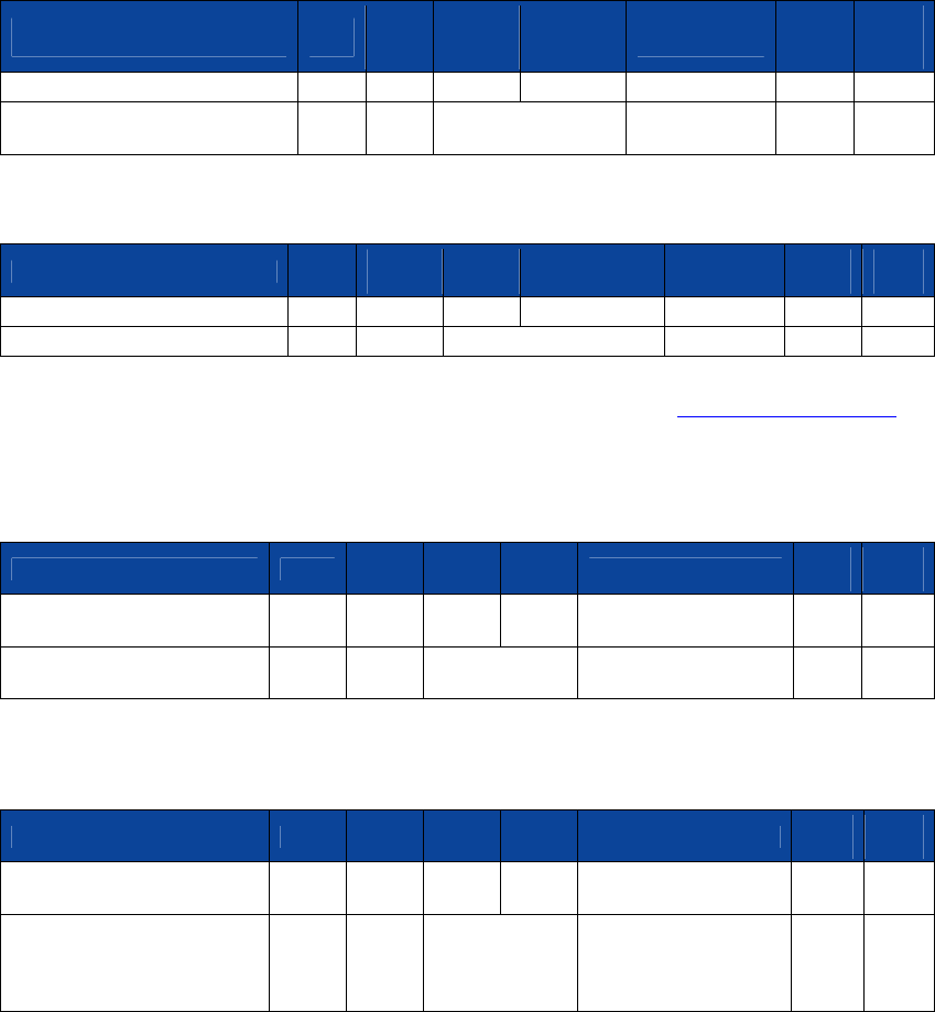
NEO Interface Developers Guide
344
16.0 Sample Scenarios and Frame Flow
Contactless MagStripe Transactions in Auto Poll Mode
For a contactless MagStripe transaction, the reader does not require any setup data from the
terminal.
1. Command: Set Poll Mode (Auto Poll)
Header Cmd
Sub-
Cmd
DLen
(MSB)
DLen
(LSB) Data CRC
(LSB)
CRC
(MSB)
56 69 56 4F 74 65 63 68 32 00
01h
01h
00h
01h
00
F6h
24h
ViVOtech2\0 DLen = 1 decimal
Auto Poll
Mode
Response: OK
Header Cmd
Status
Code
DLen
(MSB)
DLen
(LSB)
Data
CRC
(MSB)
CRC
(LSB)
56 69 56 4F 74 65 63 68 32 00
01h
00
00h
00h
12h
53h
ViVOtech2\0
OK
DLen = 0 decimal
None
Reader starts polling for cards. The Terminal should keep checking for data from the reader. If a
card has been read, data is available, otherwise there is no data. The Get Transaction Result
command is for retrieving the data. This command is not required for the reader to poll for
cards or to carry out a transaction.
2. Command: Get Transaction Result
Header Cmd
Sub-
Cmd
DLen
(MSB)
DLen
(LSB)
Data
CRC
(LSB)
CRC
(MSB)
56 69 56 4F 74 65 63 68 32
00 03h 00h 00h 00h 3Bh
FFh
ViVOtech2\0
DLen = 0
decimal
None
Response: OK, No Track Data, No Clearing Record i.e. No Transaction
Header Cmd
Status
Code
DLen
(MSB)
DLen
(LSB)
Data
CRC
(MSB)
CRC
(LSB)
56 69 56 4F 74 65 63 68 32
00
03h 00h 00h 03h 00 00 00 8Dh D0h
ViVOtech2\0 OK DLen = 3
decimal
T1 Len = 0, T2 Len =
0,
Clearing Record Not
Present
Reader continues to poll for cards. No Card has been presented so far.
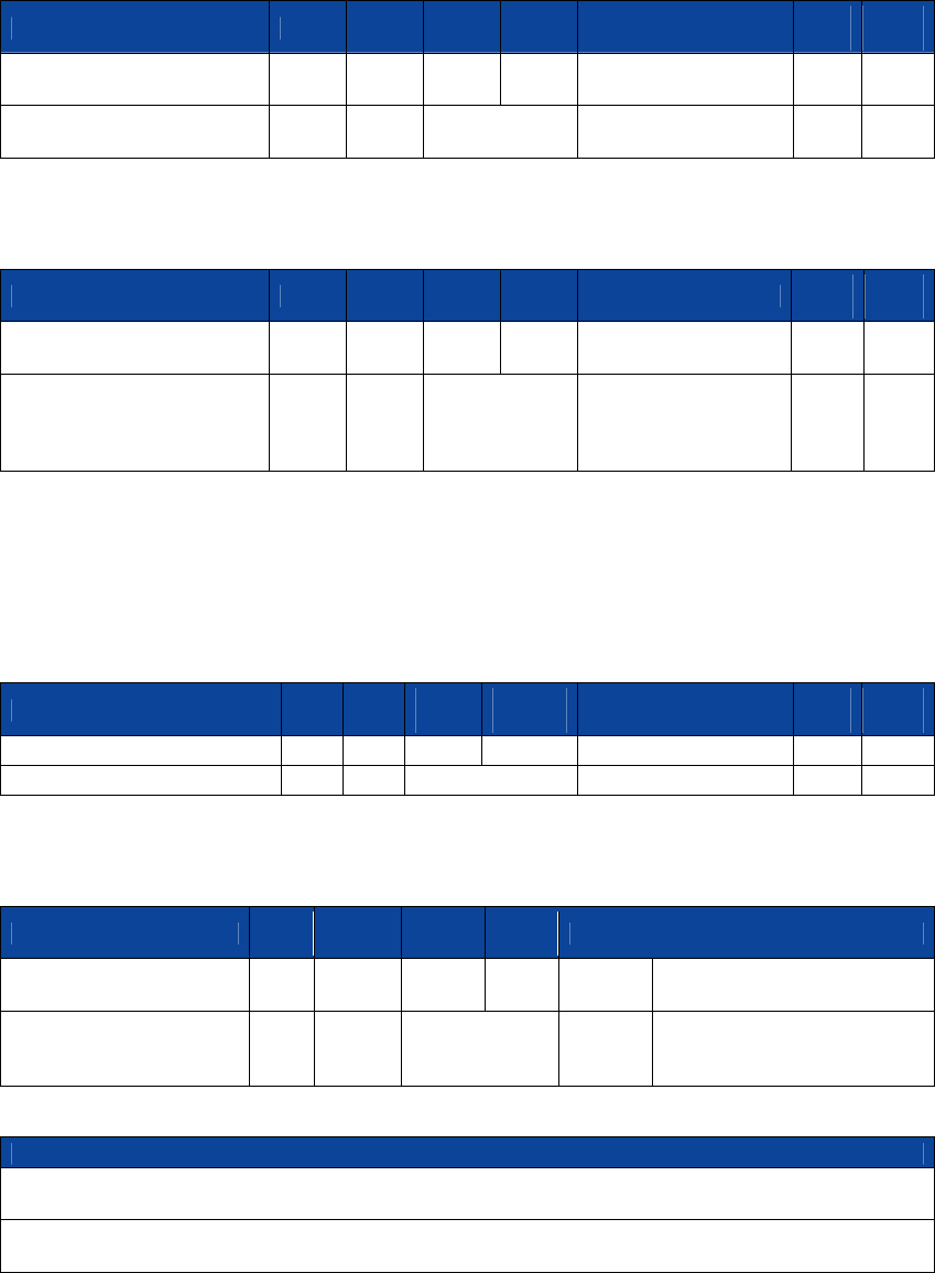
NEO Interface Developers Guide
345
3. Command: Get Transaction Result
Header Cmd
Sub-
Cmd
DLen
(MSB)
DLen
(LSB)
Data
CRC
(LSB)
CRC
(MSB)
56 69 56 4F 74 65 63 68 32
00
03h 00h 00h 00h 3Bh
FFh
ViVOtech2\0
DLen = 0
decimal None
Response: OK, No Track Data, No Clearing Record i.e. No Transaction
Header Cmd
Status
Code
DLen
(MSB)
DLen
(LSB)
Data
CRC
(MSB)
CRC
(LSB)
56 69 56 4F 74 65 63 68 32
00
03h 00h 00h 03h 00 00 00 8Dh D0h
ViVOtech2\0 OK DLen = 3
decimal
T1 Len = 0, T2 Len =
0,
Clearing Record Not
Present
Reader continues to poll for cards. No Card has been presented so far.
Reader continues to poll for cards. Card presented and accepted by the reader.
4. Command: Get Transaction Result
Header Cmd
Sub-
Cmd
DLen
(MSB)
DLen
(LSB)
Data
CRC
(LSB)
CRC
(MSB)
56 69 56 4F 74 65 63 68 32 00
03h
00h
00h
00h
3Bh
FFh
ViVOtech2\0
DLen = 0 decimal
None
Response: OK, Track1, Track2 Data available
Header Cmd
Status
Code
DLen
(MSB)
DLen
(LSB)
Data
56 69 56 4F 74 65 63 68
32 00
03h
00 00h 64h 3Ch
42 35 34 31 33 31 32 33 34 35
36 37
ViVOtech2\0 OK DLen = 100 dec
T1Len=
60
(dec)
Track 1 Data
“B54131234567”
Data
38 34 38 30 38 5E 53 4D 49 54 48 2F 4A 4F 48 4E 5E 30 35 30 38 31 30 31 33 33 35 33 37 33 33 33 36 30 37
32 32 32
Track 1 Data
“84808^SMITH/JOHN^050810133537333607222”
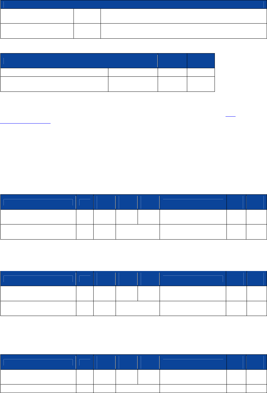
NEO Interface Developers Guide
346
Data
32 32 37 32 34 31 31 31 31
33 25h
35 34 31 33 31 32 33 34 35 36 37 38 34 38 30 38 3D 30 35 30 38
31 30 31
Track1 Data
2272411113
T2Len=
37 (dec)
Track 2 Data
“5413123456784808=0508101”
Data
CRC
(MSB)
CRC
(LSB)
39 36 30 37 39 39 37 32 34 32 31 38 33
00h
F1h
FBh
Track 2 Data
9607997242183
Clearing Record
Not Present
Contactless MagStripe card was presented and accepted by the reader before the Get
Transaction Result command. Track 1 and Track 2 data returned in response.
Contactless MagStripe Transactions in Poll on Demand Mode
For a contactless MagStripe transaction, the reader does not require any setup data from the
terminal.
1. Command: Set Poll Mode (Poll on Demand)
Header Cmd
Sub-
Cmd
DLen
(MSB)
DLen
(LSB)
Data
CRC
(LSB)
CRC
(MSB)
56 69 56 4F 74 65 63 68 32
00 01h
01h 00h 01h 01h D7h
34h
ViVOtech2\0
DLen = 1
decimal
Poll on Demand Mode
Response: OK
Header Cmd
Status
Code
DLen
(MSB)
DLen
(LSB)
Data
CRC
(MSB)
CRC
(LSB)
56 69 56 4F 74 65 63 68 32
00
01h
00h 00h 00h 12h 53h
ViVOtech2\0 OK
DLen = 0
decimal None
Reader stops polling for cards. Terminal has to issue an Activate command to allow the reader
to poll for a card and carry out a transaction.
2. Command: Activate (MagStripe/EMV)
Header Cmd
Sub-
Cmd
DLen
(MSB)
DLen
(LSB)
Data
CRC
(LSB)
CRC
(MSB)
56 69 56 4F 74 65 63 68 32
00 02h
01h 00h 01h 0Ah 6Eh
6Bh
ViVOtech2\0
DLen = 1
Timeout = 10 Seconds
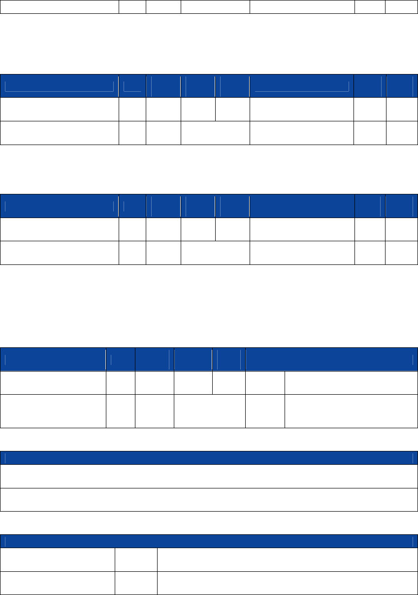
NEO Interface Developers Guide
347
decimal
(decimal)
Reader starts polling for cards. No card is presented. Reader stops polling after 10 seconds and
sends back a response indicating timeout.
Response: Error (Timeout) i.e. No Card Detected.
Header Cmd
Status
Code
DLen
(MSB)
DLen
(LSB)
Data
CRC
(MSB)
CRC
(LSB)
56 69 56 4F 74 65 63 68 32
00
02h
08h 00h 00h 20h 2Eh
ViVOtech2\0
Time
Out
DLen = 0
decimal None
Reader is not polling for cards.
3. Command: Activate (MagStripe/EMV)
Header Cmd
Sub-
Cmd
DLen
(MSB)
DLen
(LSB)
Data
CRC
(LSB)
CRC
(MSB)
56 69 56 4F 74 65 63 68 32
00
02h
01h 00h 01h 0Ah 6Eh
6Bh
ViVOtech2\0
DLen = 1
decimal
Timeout = 10 Seconds
(decimal)
Reader starts polling for cards. A contactless MagStripe card is presented within 10 seconds.
Reader completes transaction, even if more than ten seconds pass since Activate command was
received. After completing transaction the reader does not restart polling and just sends back
the response containing the Track1 and Track2 data.
Response: OK, Track1, Track2 Data available
Header Cmd
Status
Code
DLen
(MSB)
DLen
(LSB)
Data
56 69 56 4F 74 65 63 68
32 00 02h
00 00h 64h 3Ch
42 35 34 31 33 31 32 33 34 35
36 37
ViVOtech2\0 OK DLen = 100 dec
T1Len=
60
(dec)
Track 1 Data
“B54131234567”
Data
38 34 38 30 38 5E 53 4D 49 54 48 2F 4A 4F 48 4E 5E 30 35 30 38 31 30 31 33 33 35 33 37 33 33 33 36 30 37
32 32 32
Track 1 Data
84808^SMITH/JOHN^050810133537333607222
Data
32 32 37 32 34 31 31 31 31
33
25h
35 34 31 33 31 32 33 34 35 36 37 38 34 38 30 38 3D 30 35 30 38
31 30 31
Track1 Data
2272411113
T2Len=
37 (dec)
Track 2 Data
“5413123456784808=0508101”
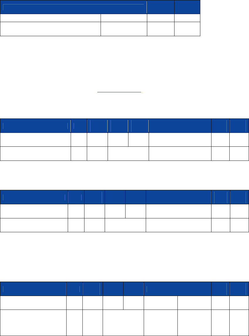
NEO Interface Developers Guide
348
Data
CRC
(MSB)
CRC
(LSB)
39 36 30 37 39 39 37 32 34 32 31 38 33
00h
F6h
7Fh
Track 2 Data
“607997242183
Clearing Record
Not Present
EMV (M/Chip) Transaction in Poll on Demand Mode
The correct CA Public Keys required by the Cards that is read have already been set up using the
Key Management Commands (refer to Key Management). This operation needs to be done only
once for each key. Keys are retained over power cycles by the reader.
1. Command: Set Poll Mode (Poll on Demand)
Header Cmd
Sub-
Cmd
DLen
(MSB)
DLen
(LSB)
Data
CRC
(LSB)
CRC
(MSB)
56 69 56 4F 74 65 63 68 32
00
01h
01h 00h 01h 01h D7h
34h
ViVOtech2\0
DLen = 1
decimal Poll on Demand Mode
Response: OK
Header Cmd
Status
Code
DLen
(MSB)
DLen
(LSB)
Data
CRC
(MSB)
CRC
(LSB)
56 69 56 4F 74 65 63 68 32
00 01h
00 00h 00h 12h 53h
ViVOtech2\0 OK
DLen = 0
decimal
None
Reader stops polling for cards. Terminal has to issue an Activate command to allow the reader
to poll for a card and carry out a transaction.
2. Command: Set Configuration (Terminal Country Code, Transaction Currency Code)
Header Cmd
Sub-
Cmd
DLen
(MSB)
DLen
(LSB)
Data
CRC
(LSB)
CRC
(MSB)
56 69 56 4F 74 65 63 68
32 00 04h
00h 00h 0Ah
9F 1A 02 00
56
5F 2A 02 09
78 69h
03h
ViVOtech2\0 DLen = 10
decimal
TLV
Terminal
Country
Code
TLV Trans
Currency
Code
Assuming the current terminal values is used for all other parameters (unless specified
otherwise in Activate command).
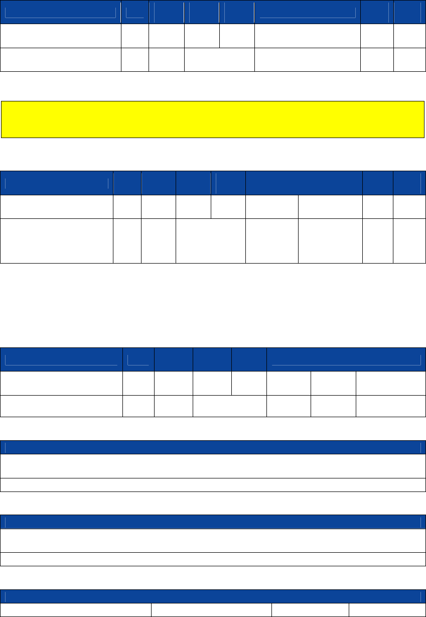
NEO Interface Developers Guide
349
Response: OK
Header Cmd
Status
Code
DLen
(MSB)
DLen
(LSB)
Data
CRC
(MSB)
CRC
(LSB)
56 69 56 4F 74 65 63 68 32
00 04h
00 00h 00h AEh 16h
ViVOtech2\0 OK
DLen = 0
decimal
None
Reader is still not polling for cards.
Note: These parameter values may not apply to all cards. The terminal has to make sure that
correct values have been defined for the parameters based on card requirements otherwise a
transaction fails.
3. Command: Activate (MagStripe/EMV)
Header Cmd
Sub-
Cmd
DLen
(MSB)
DLen
(LSB)
Data
CRC
(LSB)
CRC
(MSB)
56 69 56 4F 74 65 63 68
32 00 02h
01h 00h 06h 0Ah
9A 03 05 08
18 77h
1Dh
ViVOtech2\0 DLen = 1
decimal
Timeout =
10
Seconds
(decimal)
TLV
Transaction
Date
Reader starts polling for cards. A contactless EMV (M/Chip) card is presented within 10 seconds.
Reader completes transaction, even if more than ten seconds pass since Activate command was
received. After completing transaction the reader does not restart polling and just sends back
the response containing the Clearing Record data.
Response: OK, Clearing Record and additional Data available
Header Cmd
Status
Code
DLen
(MSB)
DLen
(LSB)
Data
56 69 56 4F 74 65 63 68 32
00 02h
00 00h ABh 00h 00h 01h
ViVOtech2\0 OK DLen = 171 dec
T1Len =
0 (dec)
T2Len = 0
(dec)
Clearing Record
Present
Data
E1 56 9F 1A 02 01 58 9F 02 06 00 00 00 00 00 01 5F 2A 02 09 01 9A 03 05 08 02 9C 01 00 95 05 00 00 00 00
00 9F 37
Clearing Record (DE 055)
Data
04 84 77 98 32 82 02 58 80 9F 26 08 02 BB 21 5D D9 06 94 01 9F 27 01 40 9F 10 12 02 10 90 08 01 22 30 00
00 00 00
Clearing Record (DE 055)
Data
00 00 00 00 15 00 FF 9F 36 02 00 D0
5A 08 54 12 34 00 00 00 00
5F 34 01 00
5F 24 03 10 07
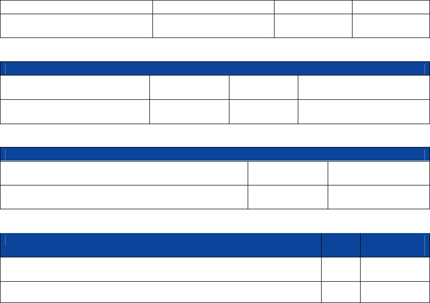
NEO Interface Developers Guide
350
19
31
Clearing Record (DE 055) TLV App PAN
TLV PAN Seq
Num
TLV App
Expiration Date
Data
50 0A 4D 61 73 74 65 72 43 61 72
64
9F 34 03 00 1F
03
9F 45 02 DA
C0
9F 4C 08 00 00 00 00 00 00 00
00
TLV Application Label CVM Results
Data Auth
Code
ICC Dynamic Number
Data
57 13 54 12 34 00 00 00 00 19 D1 00 72 01 14 43 14 31 00
00 0F 56 00 9B 02 C8 00
TLV Track 2 Equivalent Data
TLV Track 1
Equivalent Data
Transaction Status
Information
Data
CRC
(MSB)
CRC
(LSB)
5F 20 1A 53 20 20 20 20 20 20 20 20 20 20 20 20 20 20 20 20 20 20 20 20 20 20
20 20 20 27h 60h
Cardholder Name

NEO Interface Developers Guide
351
Appendix A.1: User Experience Illustration
Following are list of messages and the message flow for one user experience.
Table 80: Summary of LCD Messages
User Interface States ViVOtech User Experience
Idle
00: Idle Message (Welcome)
Polling
01: Present card (Please Present Card)
Time out or Transaction Cancel
02: Time Out or Transaction cancel (No Card)
Transaction In Progress
03: Transaction between reader and card is in the middle
(Processing…)
Transaction Succeed
04: Transaction Pass (Thank You)
Transaction Fail
05: Transaction Fail (Fail)
Configurable messages
06: Amount (Amount $ 0.00 Tap Card)
07: Balance or Offline Available funds (Balance $ 0.00)
08: Insert or Swipe card (Use Chip & PIN)
09: Try Again(Tap Again)
0A: Indicate the custom to present only one card
(Present 1 card only)
0B: Indicate the custom to wait for
authentication/authorization (Wait)
The flow diagram below illustrates how an external UI may be controlled, using asynchronous UI
events.
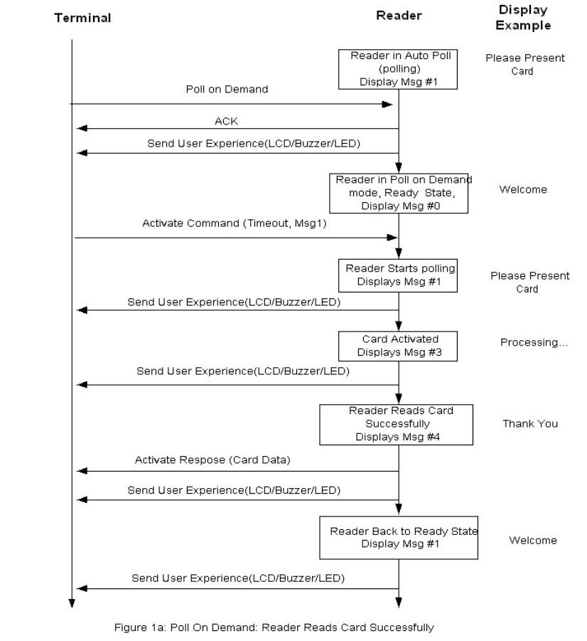
NEO Interface Developers Guide
352

NEO Interface Developers Guide
353
Appendix A.2: Audible User Interface
Some readers do not have an LCD display. In that case, audible tones and lights indicate the
status and when an action must be taken.
The following table describes the audible user interface tones
Table 4: Definition of Audible Tones
Tone Name Sound
Alert
Two short beeps
Card Read Complete
One long beep
Check Phone
Three short beeps
The Alert tone is an indication to the card user that something unusual has occurred and some
action must be taken (for example, insert a card, swipe a card, check your mobile phone, use
one card at a time, etc.).
The following table describes the audible tones emitted by the reader for each of the interfaces
under various conditions:
Table 5 : Meaning of Audible Tones by Interface
Card/ Interface Type Tone Reason for Tone
Contactless
Check Phone
Consumer interaction required (user
needs to do something on the phone,
such as enter a PIN)
Alert
Card Read Error
Collision Detected
Unsupported Card
Application Error
No Response after Restart (only for
VCPS2.1.1 and ExpressPay 3.0)
Card Read Complete +
Alert
Card Read Complete and Card Error
Card Read Complete & switch to
another interface
Card Read Complete
Transaction Approved, Offline
Transaction Declined Offline (see status
and error codes)
Transaction Approved Online
Transaction Declined Online
Contact
Alert
Card Removed
Transaction terminated with Error
Switch from Contact to MagStripe
Interface
Card Read Complete
Transaction Approved, Offline
Transaction Declined, Offline
Transaction Approved, Online
Transaction Declined, Online
MagStripe
Alert
Card Swipe Error
Card Read Complete
Card Swiped Successfully
NEO Interface Developers Guide
354
Appendix A.3: Configurable AID Use Examples
This is the communications between a Configurable AID capable reader and an attached PC
simulating a POS.
Disable System AID
From POS →
56 69 56 4F 74 65 63 68 32 00 04 04 00 0A 9F 06 07 A0 00 00 00 04 10 10 25 59
From Reader ←
56 69 56 4F 74 65 63 68 32 00 04 00 00 00 AE 16
Uses the DCA Command (Delete Configurable AID - Cmd 4, Sub Cmd 4)
9F06 07 A0 00 00 00 04 10 10 – Selects the AID Number
Enable System AID
From POS →
56 69 56 4F 74 65 63 68 32 00 04 02 00 0E FF E4 01 00 9F 06 07 A0 00 00 00 04 10 10 D2 A8
From Reader ←
56 69 56 4F 74 65 63 68 32 00 04 07 00 00 2B 86
Uses the SCA Command (Set Configurable AID - Cmd 4, Sub Cmd 2)
FFE4 01 00 - Selects Group 0
9F06 07 A0 00 00 00 04 10 10 – Selects the AID Number
Add a New Configurable AID
From POS →
56 69 56 4F 74 65 63 68 32 00 04 02 00 18 FF E4 01 00 9F 06 05 B0 12 34 56 78 FF E2 01 03 FF E1
01 01 FF E5 01 0A 09 AB
From Reader ←
56 69 56 4F 74 65 63 68 32 00 04 00 00 00 AE 16
Uses the SCA Command (Set Configurable AID - Cmd 4, Sub Cmd 2)
NEO Interface Developers Guide
355
FFE4 01 00 - Selects Group 0
9F06 05 B0 12 34 56 78 – Selects the AID Number
FFE2 01 03 – Selects Application Flow
FFE1 01 01 – Enables Partial Selection
FFE5 01 0A – Specify Maximum Partial Selection Length
Delete a Configurable AID
From POS →
56 69 56 4F 74 65 63 68 32 00 04 04 00 08 9F 06 05 B0 12 34 56 78 DF 97
From Reader ←
56 69 56 4F 74 65 63 68 32 00 04 00 00 00 AE 16
Uses the DCA Command (Delete Configurable AID - Cmd 4, Sub Cmd 4)
9F06 05 B0 12 34 56 78 – Specifies the AID to delete.
Create a New Group
From POS →
56 69 56 4F 74 65 63 68 32 00 04 03 00 0D FF E4 01 01 FF F1 06 00 00 00 01 00 00 64 03
From Reader ←
56 69 56 4F 74 65 63 68 32 00 04 00 00 00 AE 16
Uses the SCG Command (Set Configurable Group - Cmd 4, Sub Cmd 3)
FFE4 01 01 – Specify the NEW group number 1.
FFF1 06 00 00 00 01 00 00 - Terminal Transaction Limit.
Connect Existing AID to a Different Group
NEO Interface Developers Guide
356
From POS →
56 69 56 4F 74 65 63 68 32 00 04 02 00 18 FF E4 01 01 9F 06 05 B0 12 34 56 78 FF E2 01 03 FF E1
01 01 FF E5 01 0A FF 7E
From Reader ←
56 69 56 4F 74 65 63 68 32 00 04 00 00 00 AE 16
Uses the SCA Command (Set Configurable AID - Cmd 4, Sub Cmd 2)
FFE4 01 01 – Specify the NEW group number 1.
9F06 05 B0 12 34 56 78 - Specifies the AID.
FFE2 01 03 – Selects Application Flow
FFE1 01 01 – Enables Partial Selection
FFE5 01 0A – Specify Maximum Partial Selection Length
NEO Interface Developers Guide
357
Return Existing AID to Group 0
From POS →
56 69 56 4F 74 65 63 68 32 00 04 02 00 18 FF E4 01 00 9F 06 05 B0 12 34 56 78 FF E2 01 03 FF E1
01 01 FF E5 01 0A 09 AB
From Reader ←
56 69 56 4F 74 65 63 68 32 00 04 00 00 00 AE 16
Uses the SCA Command (Set Configurable AID - Cmd 4, Sub Cmd 2)
FFE4 01 00 – Specify Group number 0.
9F06 05 B0 12 34 56 78 - Specifies the AID.
FFE2 01 03 – Selects Application Flow
FFE1 01 01 – Enables Partial Selection
FFE5 01 0A – Specify Maximum Partial Selection Length
Delete a Group
From POS →
56 69 56 4F 74 65 63 68 32 00 04 05 00 04 FF E4 01 01 0C 5D
From Reader ←
56 69 56 4F 74 65 63 68 32 00 04 00 00 00 AE 16
Uses the DCG Command (Delete Configurable Group - Cmd 4, Sub Cmd 5)
FF E4 01 01 - Specify Group number to delete.

NEO Interface Developers Guide
358
Appendix A.4: Demo Utilities and Sample Code
The following PC-based demo utilities and sample code are available from IDTECH on request.
Item
Description
ViVOPing.zip
Visual C++ Project and C files containing the sample code given in
Appendix A.1 in this document.
ViVOPing.exe
Executable File for the sample code given in this Document.
RFIDRead.exe
Demo Utility that polls ViVOpay for Track Data.
Sample_RFIDRead.zip
Source Code for the RFIDRead Utility (demonstrates use of Ping as
well as Get Track Data Commands).
NEO Interface Developers Guide
359
Appendix A.5: Firmware FAQ
The following FAQs attempt to answer common issues:
Q1. How do I identify the reader type from my application?
A. You can identify the reader type by checking the firmware:
Q2. Can you tell me which Terminal Types the reader supports?
A. The Vendi reader supports terminal type 24 – unattended, online only.
Q3. How many keys can I load onto the reader?
A. For CA public key, there is no limitation till the flash is full.
The Kiosk III reader allows for storage of up to a maximum of 60 keys which are uniquely
identified as a key index in each payment scheme(RID).
Q4. How can I guarantee that all settings are erased in my reader when I
load a new release of firmware?
A. Use the Set Configuration Defaults Command (04-09) to re-initialize the setting to default
values.
Q5. Why does my MasterCard application ignore the Terminal Contactless
Transaction Limit (FFF1) and the CVM Required Limit (FFF5) Tags?
A. The Terminal Contactless Transaction Limit (FFF1) and the CVM Required Limit (FFF5) Tags
are used by Visa and not by MasterCard. MasterCard uses the Floor Limit and the CVM List
structure described in the MasterCard specifications.
Q6. How do I enable Maestro cards in reader?
A. To enable Maestro cards, apply the following script.
---------CUT---------
AID SET
FFE4 01 00 ; Group 0
9F06 07 A0 00 00 00 04 30 60 ; AID Number
NEO Interface Developers Guide
360
;FFE6 01 00 ; AID Disabled OFF
END
---------CUT---------
Q7. What applications are supported?
A. The following applications are supported and certified.
EMVCo
- CCPS 2.3.1
MasterCard
- M/Chip v3.02
- M/Stripe v3.3
Visa
- VCPS (qVSDC & MSD) 2.1.3
- Reader Implementation Notes 1.1 Licensed (IRWIN-compliant)
Amex
- ExpressPay 3.0
Discover
- Discover DPAS 1.0 Zip 3.1.2, v1.00
Interac
- Flash 1.5
Q8. Whenever I try to load a key into the device it fails, with the error
EMV_KM_EC_NO_FREE_KEY_SLOTS. Why is that?
A. You must first delete a key from a slot before you can load a new one.
Q9. How do I manage the FAIL message on the reader?
A. The way that we expect it to work is when a transaction error occurs; the reader sends error
codes back to the host. The host can use the error code to determine the appropriate message
to display on the reader using Control User Interface command. You may wish to replace the
message FAIL (05) with a more user friendly message or a blank message and manage it yourself.

NEO Interface Developers Guide
361
Q10. Why am I receiving timeouts when I try to load CAP keys into my
reader using the key loading API?
A. A possible reason for the time out is because the ‘Data Length’ in the Command Frame is
greater than the actual data length of the data field being sent, therefore the ViVOpay reader
waits for more data and times out. Please ensure that the data length matches the actual size
of the data field being sent.
Q11. On certain Visa cards the PAN (tag 5A) and Application Expiration
Date (tag 5F24) are returned as zero length. Shouldn’t the reader provide
both PAN and expiry date because the Visa Contactless Payment
Specification, Protocol 2.0.2 says: "Note that the PAN and the Expiration
Date are obtained by the reader from the Track 2 Equivalent Data"?
A. The reader will only return those tags if they are present in the card, they will then be
provided in the transaction results.
Note: The reader will not provide the tags if the card does not send then in the Response
Frame.
Q12. I am using the Configurable AID features and my application is not
able to correctly identify all Visa Cards.
A. Visa requires partial selection of the AIDs to be set in all PayWave applications. Please ensure
that partial selection is enabled as shown below.
---------CUT---------
AID SET
FFE4 01 02 ; Group
9F06 07 A0 00 00 00 03 10 10 ; Visa
FFE5 01 10 ; include both of these tags Max AID length and
FFE1 01 01 ; allow partial selection
END
---------CUT---------
Note: Partial selection is enabled by default for specific System AIDs (including Visa) but
when you reprogram the AID you have to specifically enable partial selection.
NEO Interface Developers Guide
362

NEO Interface Developers Guide
363
Appendix A.6: TDES Data Encryption Examples
Examples are given for MSR data as well as ICC data. Note that data for the former will be in a
different format than data for the latter. The former uses the Enhanced Encrypted MSR Data
Output Format (see later appendix, or see ID TECH document P/N 80000403-001). By contrast,
ICC data comes back as TLV data, preceded by a ViVOtech2 header with command and response
bytes and two length bytes, and followed by a 16-bit CRC.
Step 1: Data encryption Enable
[TX] - 56 69 56 4F 74 65 63 68 32 00 C7 36 00 01 01 B7 2E
[RX] - 56 69 56 4F 74 65 63 68 32 00 C7 00 00 00 86 6E
Step 2: Do a transaction
Example: Burst Mode OFF and Poll on Demand mode
Burst off
[TX] - 56 69 56 4F 74 65 63 68 32 00 04 00 00 04 FF F7 01 00 B9 2E
[RX] - 56 69 56 4F 74 65 63 68 32 00 04 00 00 00 AE 16
Poll on demand
[TX] - 56 69 56 4F 74 65 63 68 32 00 01 01 00 01 01 D7 34
[RX] - 56 69 56 4F 74 65 63 68 32 00 01 00 00 00 12 53
Activate transaction and then Swipe card or Tap card
[TX] - 56 69 56 4F 74 65 63 68 32 00 02 01 00 0A 0A 9F 02 06 00 00 00 00
10 00 AB 6C
[RX] - MSR and contactless Card DATA As below
--MSR card data
The data will come back in the Enhanced Encrypted MSR Data Output Format, framed as follows:
<Preamble> <Attribution> < MSR TLV> <CRC>
See Appendix A.11 for format details.
Raw data:
Raw data:
56 69 56 4F 74 65 63 68 32 00 Protocol Header (ViVOtech2\0)
02 Command
00 Status Code
01 3D Data Length MSB & LSB

NEO Interface Developers Guide
364
88 Attribution
DF EE 23 MSR Tag
82 MSR Data length indicator
01 25 MSR Data length
02 1F 01 80 1F 44 28 00 83 9B 25 2A Enhanced Encrypted MSR Field Data
36 35 31 30 2A 2A 2A 2A 2A 2A 2A 2A (see Appendix A.11 for format)
30 30 32 36 5E 43 41 52 44 2F 49 4D
41 47 45 20 30 33 20 20 20 20 20 20
20 20 20 20 20 20 20 5E 2A 2A 2A 2A
2A 2A 2A 2A 2A 2A 2A 2A 2A 2A 2A 2A
2A 2A 2A 2A 3F 2A 3B 36 35 31 30 2A
2A 2A 2A 2A 2A 2A 2A 30 30 32 36 3D
2A 2A 2A 2A 2A 2A 2A 2A 2A 2A 2A 2A
2A 2A 2A 2A 2A 2A 2A 2A 3F 2A C7 27
B0 60 AB FC 2B 62 4C 4D 6E 59 96 E2
2D 84 8D 87 D6 E3 82 0D 57 37 4F 6D
3F B3 1F 75 06 1A DC 17 89 FB C3 C7
50 C7 5D 06 65 00 04 08 CA B4 CA 0C
62 47 62 EE 86 0F BD 54 17 E0 FD D5
7E 1D A9 C9 FA 98 FB DF 49 CA CE 1B
DC 33 AA 1A DD A5 D6 52 C6 FC CF C5
DC A9 46 A8 07 1F 1C 13 1B 7F E6 5F
75 06 01 CE C6 1E 8A 64 0E 1C 2B EC
80 D4 51 48 AB 78 7E 8B 8D 05 DC 8A
C9 07 9E FC 98 53 27 0B ED B9 10 02
52 D6 AA D8 46 CB 85 69 24 FE 7C 93
52 0B 36 DA D9 25 00 00 00 00 00 00
00 00 00 00 62 99 49 01 2C 00 04 60
00 01 C1 0B 03
9F 39 01 90 Point of Service (POS) Entry Mode
FF EE 01 04 ViVOPay Group Tag
DF 30 01 0C Track Data Source
DF EE 26 01 88 Encrypt Information
76 EA CRC (MSB & LSB)
NEO Interface Developers Guide
365
-- MasterCard Contactless (PayPass) card example:
The data will come back in the encrypted ICC format:
<PREAMBLE><Attribution Byte><KSN TLV><Track1 TLV(optional)><Track2
TLV(optional)><Clear Record TLV(optional)><Other TLVs><CRC>
The preamble is 14 bytes, as before (see example immediately above). The Attribution Byte will have a
value of 0x81 or 0x83 for contactless TDES or AES, respectively. (The lowest bit is a Contactless flag. The
second bit is a TDES/AES flag. The highest bit is a Encryption State flag. See Chapter 9.) The TLV data
section consists of tag, length, value triplets. The CRC is a 16-bit cyclic redundancy check of the entire data
packet, including the preamble.
Raw data:
56 69 56 4F 74 65 63 68 32 00 02 23 01 98 81 FF EE 12 0A 62 99 49 01 2C
00 04 60 00 02 82 02 00 00 95 05 00 00 00 00 00 9A 03 14 08 10 9C 01 00
5F 2A 02 08 40 9F 02 06 00 00 00 00 10 00 9F 03 06 00 00 00 00 00 00 9F
06 07 A0 00 00 00 04 10 10 9F 09 02 00 02 9F 1A 02 08 40 9F 1E 08 30 30
30 30 30 30 30 30 9F 21 03 12 02 37 9F 33 03 00 00 E8 9F 34 03 00 00 00
9F 35 01 25 9F 36 02 05 AB 9F 37 04 0F 0A 1A E5 9F 39 01 91 9F 53 01 00
DF 81 29 08 30 F0 F0 00 30 F0 FF 00 FF 81 06 44 DF 81 2A C1 20 10 18 E2
2A 40 63 49 89 C9 4B B1 01 3A D7 4A F6 1D 64 CF 42 5F 33 83 0A 9B BB 63
46 20 7A 72 76 DF 81 2B C1 10 16 DA F4 11 79 F9 0B A4 DC D0 64 31 65 31
CA B0 DF 81 15 06 00 00 00 00 00 FF FF 81 05 79 50 0A 4D 61 73 74 65 72
43 61 72 64 84 07 A0 00 00 00 04 10 10 9F 6D 02 00 01 56 C1 40 A5 14 AD
F8 E6 42 DA 3B 13 17 F5 D3 E6 65 B8 2B 4B E4 DE 13 C3 9F 98 2D D2 18 48
5E 2B 45 9E 3C B1 23 A5 A3 0B B8 08 2C DF B8 BF 07 8C D3 63 EA 19 00 4A
B7 5F A6 61 B6 D2 06 6B 0A AA BC F9 B7 9F 6B C1 18 79 95 EB 5E 9A F6 6A
B9 F6 2F 23 74 13 EE 51 75 1A A1 A9 84 75 68 95 D6 FF EE 01 3C DF 30 01
00 DF 31 C1 20 68 0B 25 F6 29 04 FA 8B D6 F8 BB 6C 64 A5 CD C6 10 A0 A7
60 B1 B4 80 AA 67 9B D5 27 CD 39 F5 BA DF 32 C1 10 38 32 34 F5 6A D7 99
CF 9C 4C 46 06 06 BC BC F9 DF EE 26 01 81 F8 99
Parsed data:
Head : 56 69 56 4F 74 65 63 68 32 00 02 23
Data : 01 98 81
Tag : FF EE 12
Length : 0A
Value : 62 99 49 01 2C 00 04 60 00 02
Tag : 82
Length : 02
Value : 00 00
Tag : 95
Length : 05
Value : 00 00 00 00 00
Tag : 9A
Length : 03
Value : 14 08 10
Tag : 9C
NEO Interface Developers Guide
366
Length : 01
Value : 00
Tag : 5F 2A
Length : 02
Value : 08 40
Tag : 9F 02
Length : 06
Value : 00 00 00 00 10 00
Tag : 9F 03
Length : 06
Value : 00 00 00 00 00 00
Tag : 9F 06
Length : 07
Value : A0 00 00 00 04 10 10
Tag : 9F 09
Length : 02
Value : 00 02
Tag : 9F 1A
Length : 02
Value : 08 40
Tag : 9F 1E
Length : 08
Value : 30 30 30 30 30 30 30 30
Tag : 9F 21
Length : 03
Value : 12 02 37
Tag : 9F 33
Length : 03
Value : 00 00 E8
Tag : 9F 34
Length : 03
Value : 00 00 00
Tag : 9F 35
Length : 01
Value : 25
Tag : 9F 36
Length : 02
Value : 05 AB
Tag : 9F 37
Length : 04
Value : 0F 0A 1A E5
NEO Interface Developers Guide
367
Tag : 9F 39
Length : 01
Value : 91
Tag : 9F 53
Length : 01
Value : 00
Tag : DF 81 29
Length : 08
Value : 30 F0 F0 00 30 F0 FF 00
*****Embedded TLV Begin (FF 81 06 )*****
Tag : FF 81 06
Length : 44
Tag : DF 81 2A
Length : C1 20
Value(Encryption Data):
10 18 E2 2A 40 63 49 89 C9 4B B1 01 3A D7 4A F6 1D 64 CF 42 5F 33 83 0A 9B BB 63 46 20 7A 72
76
Value(Decryption Data):
DF 81 2A 18 30 30 30 31 30 30 30 30 30 31 30 30 31 31 31 31 31 31 31 31 31 31 31 32 00 00 00 00
Tag : DF 81 2B
Length : C1 10
Value(Encryption Data):
16 DA F4 11 79 F9 0B A4 DC D0 64 31 65 31 CA B0
Value(Decryption Data):
DF 81 2B 07 00 01 00 00 01 00 2F 00 00 00 00 00
Tag : DF 81 15
Length : 06
Value : 00 00 00 00 00 FF
*****Embedded TLV End (FF 81 06 )*****
*****Embedded TLV Begin (FF 81 05 )*****
Tag : FF 81 05
Length : 79
Tag : 50
Length : 0A
Value : 4D 61 73 74 65 72 43 61 72 64
Tag : 84
Length : 07
Value : A0 00 00 00 04 10 10
Tag : 9F 6D
Length : 02
Value : 00 01
Tag : 56
Length : C1 40
Value(Encryption Data):
NEO Interface Developers Guide
368
A5 14 AD F8 E6 42 DA 3B 13 17 F5 D3 E6 65 B8 2B 4B E4 DE 13 C3 9F 98 2D D2 18 48 5E 2B 45 9E
3C
B1 23 A5 A3 0B B8 08 2C DF B8 BF 07 8C D3 63 EA 19 00 4A B7 5F A6 61 B6 D2 06 6B 0A AA BC F9
B7
Value(Decryption Data):
56 3E 42 35 32 35 36 38 33 32 30 33 30 30 30 30 30 30 30 5E 53 75 70 70 6C 69 65 64 2F 4E 6F 74
5E 31 32 31 32 35 30 32 38 38 33 31 30 31 34 35 31 31 35 32 31 31 31 31 31 31 31 31 31 31 31 32
Tag : 9F 6B
Length : C1 18
Value(Encryption Data):
79 95 EB 5E 9A F6 6A B9 F6 2F 23 74 13 EE 51 75 1A A1 A9 84 75 68 95 D6
Value(Decryption Data):
9F 6B 13 52 56 83 20 30 00 00 00 D1 21 25 02 32 21 01 45 11 52 2F 00 00
*****Embedded TLV End (FF 81 05 )*****
*****Embedded TLV Begin (FF EE 01 )*****
Tag : FF EE 01
Length : 3C
Tag : DF 30
Length : 01
Value : 00
Tag : DF 31
Length : C1 20
Value(Encryption Data):
68 0B 25 F6 29 04 FA 8B D6 F8 BB 6C 64 A5 CD C6 10 A0 A7 60 B1 B4 80 AA 67 9B D5 27 CD 39 F5
BA
Value(Decryption Data):
DF 31 18 30 30 30 31 30 30 30 30 30 31 30 30 31 31 31 31 31 31 31 31 31 31 31 32 00 00 00 00 00
Tag : DF 32
Length : C1 10
Value(Encryption Data):
38 32 34 F5 6A D7 99 CF 9C 4C 46 06 06 BC BC F9
Value(Decryption Data):
DF 32 0D 30 30 30 31 30 30 30 30 30 31 30 30 32
*****Embedded TLV End (FF EE 01 )*****
Tag : DF EE 26
Length : 01
Value : 81
Tail : F8 99

NEO Interface Developers Guide
369
Burst Mode OFF and Auto Poll Mode
Burst mode OFF
[TX] - 56 69 56 4F 74 65 63 68 32 00 04 00 00 04 FF F7 01 00 B9 2E
[RX] - 56 69 56 4F 74 65 63 68 32 00 04 00 00 00 AE 16
Auto poll
[TX] - 56 69 56 4F 74 65 63 68 32 00 01 01 00 01 00 F6 24
[RX] - 56 69 56 4F 74 65 63 68 32 00 01 00 00 00 12 53
Swipe card or Tap card
Get transaction result
[TX] - 56 69 56 4F 74 65 63 68 32 00 03 00 00 00 3B FF
[RX] -MSR and contactless Card DATA As below
--MSR card data
56 69 56 4F 74 65 63 68 32 00 Protocol Header (ViVOtech2\0)
03 Command
00 Status Code
01 3D Data Length MSB & LSB
88 Attribution
DF EE 23 MSR Tag
82 MSR Data length indicator
01 25 MSR Data length
02 1F 01 80 1F 44 28 00 83 9B 25 2A Enhanced Encrypted Field Data
36 35 31 30 2A 2A 2A 2A 2A 2A 2A 2A (see Appendix A.11 for format)
30 30 32 36 5E 43 41 52 44 2F 49 4D
41 47 45 20 30 33 20 20 20 20 20 20
20 20 20 20 20 20 20 5E 2A 2A 2A 2A
2A 2A 2A 2A 2A 2A 2A 2A 2A 2A 2A 2A
2A 2A 2A 2A 3F 2A 3B 36 35 31 30 2A
2A 2A 2A 2A 2A 2A 2A 30 30 32 36 3D
2A 2A 2A 2A 2A 2A 2A 2A 2A 2A 2A 2A
2A 2A 2A 2A 2A 2A 2A 2A 3F 2A C7 27
B0 60 AB FC 2B 62 4C 4D 6E 59 96 E2
2D 84 8D 87 D6 E3 82 0D 57 37 4F 6D
3F B3 1F 75 06 1A DC 17 89 FB C3 C7
50 C7 5D 06 65 00 04 08 CA B4 CA 0C
62 47 62 EE 86 0F BD 54 17 E0 FD D5
7E 1D A9 C9 FA 98 FB DF 49 CA CE 1B
DC 33 AA 1A DD A5 D6 52 C6 FC CF C5
DC A9 46 A8 07 1F 1C 13 1B 7F E6 5F
NEO Interface Developers Guide
370
75 06 01 CE C6 1E 8A 64 0E 1C 2B EC
80 D4 51 48 AB 78 7E 8B 8D 05 DC 8A
C9 07 9E FC 98 53 27 0B ED B9 10 02
52 D6 AA D8 46 CB 85 69 24 FE 7C 93
52 0B 36 DA D9 25 00 00 00 00 00 00
00 00 00 00 62 99 49 01 2C 00 04 60
00 01 C1 0B 03
9F 39 01 90 Point of Service (POS) Entry Mode
FF EE 01 04 ViVOPay Group Tag
DF 30 01 0C Track Data Source
DF EE 26 01 88 Encrypt Information
FD 71 CRC (MSB & LSB)
-- MasterCard Contactless (PayPass) card data
Raw data:
56 69 56 4F 74 65 63 68 32 00 03 23 01 98 81 FF EE 12 0A 62 99 49 01 2C
00 04 60 00 04 82 02 00 00 95 05 00 00 00 00 00 9A 03 14 08 10 9C 01 00
5F 2A 02 08 40 9F 02 06 00 00 00 00 00 01 9F 03 06 00 00 00 00 00 00 9F
06 07 A0 00 00 00 04 10 10 9F 09 02 00 02 9F 1A 02 08 40 9F 1E 08 30 30
30 30 30 30 30 30 9F 21 03 12 02 53 9F 33 03 00 00 E8 9F 34 03 00 00 00
9F 35 01 25 9F 36 02 05 AC 9F 37 04 3E CE 50 B9 9F 39 01 91 9F 53 01 00
DF 81 29 08 30 F0 F0 00 30 F0 FF 00 FF 81 06 44 DF 81 2A C1 20 C6 9A 82
5D 19 7A 9E AE FC CF 50 39 66 88 21 C2 C9 EF 3B A9 B6 30 32 0E 7F 19 C0
4A A0 77 C0 EC DF 81 2B C1 10 92 95 3B 08 DF EA 80 31 E5 7F BB D2 91 55
3A 38 DF 81 15 06 00 00 00 00 00 FF FF 81 05 79 50 0A 4D 61 73 74 65 72
43 61 72 64 84 07 A0 00 00 00 04 10 10 9F 6D 02 00 01 56 C1 40 AA 67 C3
F5 0A 86 04 3B A9 B3 86 09 C8 88 D5 20 69 24 2D 63 AC 2B 8F 05 83 67 F3
66 44 EB 61 D2 70 F9 61 A4 7B 91 60 4C 7C A5 C9 AA 09 9E 2C 53 FA 7E 6E
C9 C7 8D EC AF C0 91 D9 37 ED 30 F6 26 9F 6B C1 18 0E 0C 92 E0 FC 96 1A
19 EC EB E1 E8 40 E4 8B D1 37 7F B0 9C DF 6D EB D6 FF EE 01 3C DF 30 01
00 DF 31 C1 20 FC 47 AC 22 D0 C7 AE 1B E9 A4 AD F2 7F 8E 60 B1 4E F0 92
73 5D EF CE 9B BA 3D CA BF B1 48 40 BB DF 32 C1 10 A3 1C EC AE 13 AF 03
7C 3A DE EC 45 7B BC DA 8A DF EE 26 01 81 28 F9
Parsed data:
Head : 56 69 56 4F 74 65 63 68 32 00 03 23
Data : 01 98 81
Tag : FF EE 12
Length : 0A
Value : 62 99 49 01 2C 00 04 60 00 04
Tag : 82
Length : 02
Value : 00 00
NEO Interface Developers Guide
371
Tag : 95
Length : 05
Value : 00 00 00 00 00
Tag : 9A
Length : 03
Value : 14 08 10
Tag : 9C
Length : 01
Value : 00
Tag : 5F 2A
Length : 02
Value : 08 40
Tag : 9F 02
Length : 06
Value : 00 00 00 00 00 01
Tag : 9F 03
Length : 06
Value : 00 00 00 00 00 00
Tag : 9F 06
Length : 07
Value : A0 00 00 00 04 10 10
Tag : 9F 09
Length : 02
Value : 00 02
Tag : 9F 1A
Length : 02
Value : 08 40
Tag : 9F 1E
Length : 08
Value : 30 30 30 30 30 30 30 30
Tag : 9F 21
Length : 03
Value : 12 02 53
Tag : 9F 33
Length : 03
Value : 00 00 E8
Tag : 9F 34
Length : 03
Value : 00 00 00
Tag : 9F 35
Length : 01
Value : 25
NEO Interface Developers Guide
372
Tag : 9F 36
Length : 02
Value : 05 AC
Tag : 9F 37
Length : 04
Value : 3E CE 50 B9
Tag : 9F 39
Length : 01
Value : 91
Tag : 9F 53
Length : 01
Value : 00
Tag : DF 81 29
Length : 08
Value : 30 F0 F0 00 30 F0 FF 00
*****Embedded TLV Begin (FF 81 06 )*****
Tag : FF 81 06
Length : 44
Tag : DF 81 2A
Length : C1 20
Value(Encryption Data):
C6 9A 82 5D 19 7A 9E AE FC CF 50 39 66 88 21 C2 C9 EF 3B A9 B6 30 32 0E 7F 19 C0 4A A0 77 C0
EC
Value(Decryption Data):
DF 81 2A 18 30 30 30 31 30 30 30 30 30 31 30 30 31 31 31 31 31 31 31 31 31 31 31 32 00 00 00 00
Tag : DF 81 2B
Length : C1 10
Value(Encryption Data):
92 95 3B 08 DF EA 80 31 E5 7F BB D2 91 55 3A 38
Value(Decryption Data):
DF 81 2B 07 00 01 00 00 01 00 2F 00 00 00 00 00
Tag : DF 81 15
Length : 06
Value : 00 00 00 00 00 FF
*****Embedded TLV End (FF 81 06 )*****
*****Embedded TLV Begin (FF 81 05 )*****
Tag : FF 81 05
Length : 79
Tag : 50
Length : 0A
Value : 4D 61 73 74 65 72 43 61 72 64
Tag : 84
Length : 07
NEO Interface Developers Guide
373
Value : A0 00 00 00 04 10 10
Tag : 9F 6D
Length : 02
Value : 00 01
Tag : 56
Length : C1 40
Value(Encryption Data):
AA 67 C3 F5 0A 86 04 3B A9 B3 86 09 C8 88 D5 20 69 24 2D 63 AC 2B 8F 05 83 67 F3 66 44 EB 61
D2
70 F9 61 A4 7B 91 60 4C 7C A5 C9 AA 09 9E 2C 53 FA 7E 6E C9 C7 8D EC AF C0 91 D9 37 ED 30 F6
26
Value(Decryption Data):
56 3E 42 35 32 35 36 38 33 32 30 33 30 30 30 30 30 30 30 5E 53 75 70 70 6C 69 65 64 2F 4E 6F 74
5E 31 32 31 32 35 30 32 30 35 39 31 30 31 34 35 32 31 35 33 31 31 31 31 31 31 31 31 31 31 31 32
Tag : 9F 6B
Length : C1 18
Value(Encryption Data):
0E 0C 92 E0 FC 96 1A 19 EC EB E1 E8 40 E4 8B D1 37 7F B0 9C DF 6D EB D6
Value(Decryption Data):
9F 6B 13 52 56 83 20 30 00 00 00 D1 21 25 02 51 71 01 45 21 53 2F 00 00
*****Embedded TLV End (FF 81 05 )*****
*****Embedded TLV Begin (FF EE 01 )*****
Tag : FF EE 01
Length : 3C
Tag : DF 30
Length : 01
Value : 00
Tag : DF 31
Length : C1 20
Value(Encryption Data):
FC 47 AC 22 D0 C7 AE 1B E9 A4 AD F2 7F 8E 60 B1 4E F0 92 73 5D EF CE 9B BA 3D CA BF B1 48 40
BB
Value(Decryption Data):
DF 31 18 30 30 30 31 30 30 30 30 30 31 30 30 31 31 31 31 31 31 31 31 31 31 31 32 00 00 00 00 00
Tag : DF 32
Length : C1 10
Value(Encryption Data):
A3 1C EC AE 13 AF 03 7C 3A DE EC 45 7B BC DA 8A
Value(Decryption Data):
DF 32 0D 30 30 30 31 30 30 30 30 30 31 30 30 32
*****Embedded TLV End (FF EE 01 )*****
Tag : DF EE 26
Length : 01
Value : 81
Tail : 28 F9

NEO Interface Developers Guide
374
Appendix A.7: AES Data Encryption Examples
Examples are given for MSR data as well as ICC data. Note that data for the former will be in a
different format than data for the latter. The former uses the Enhanced Encrypted MSR Data
Output Format (see later appendix, or see ID TECH document P/N 80000403-001). By contrast,
ICC data comes back as TLV data, preceded by a ViVOtech2 header with command and response
bytes and two length bytes, and followed by a 16-bit CRC.
Step 1 Data encryption Enable
[TX] - 56 69 56 4F 74 65 63 68 32 00 C7 36 00 01 01 B7 2E
[RX] - 56 69 56 4F 74 65 63 68 32 00 C7 00 00 00 86 6E
Step 2 Do a transaction
Burst Mode OFF and Poll on Demand Mode
Burst off
[TX] - 56 69 56 4F 74 65 63 68 32 00 04 00 00 04 FF F7 01 00 B9 2E
[RX] - 56 69 56 4F 74 65 63 68 32 00 04 00 00 00 AE 16
Poll on demand
[TX] - 56 69 56 4F 74 65 63 68 32 00 01 01 00 01 01 D7 34
[RX] - 56 69 56 4F 74 65 63 68 32 00 01 00 00 00 12 53
Activate transaction and then Swipe card or Tap card
[TX] - 56 69 56 4F 74 65 63 68 32 00 02 01 00 0A 0A 9F 02 06 00 00 00 00
10 00 AB 6C
[RX] - MSR and contactless Card DATA As below
--MSR card data
56 69 56 4F 74 65 63 68 32 00 Protocol Header (ViVOtech2\0)
02 Command
00 Status Code
01 4D Data Length MSB & LSB
8A Attribution
DF EE 23 MSR Tag
82 MSR Data length indicator
01 35 MSR Data length
02 2F 01 80 1F 44 28 00 93 9B 25 2A Enhanced Encrypted MSR Field Data
36 35 31 30 2A 2A 2A 2A 2A 2A 2A 2A (see Appendix A.11 for format)
NEO Interface Developers Guide
375
30 30 32 36 5E 43 41 52 44 2F 49 4D
41 47 45 20 30 33 20 20 20 20 20 20
20 20 20 20 20 20 20 5E 2A 2A 2A 2A
2A 2A 2A 2A 2A 2A 2A 2A 2A 2A 2A 2A
2A 2A 2A 2A 3F 2A 3B 36 35 31 30 2A
2A 2A 2A 2A 2A 2A 2A 30 30 32 36 3D
2A 2A 2A 2A 2A 2A 2A 2A 2A 2A 2A 2A
2A 2A 2A 2A 2A 2A 2A 2A 3F 2A EB AB
97 04 89 00 E7 C6 5D BC FB BC F9 B3
B5 CA FC 1F 2C A0 AF 39 EC D2 C0 84
15 E4 E9 B9 9D 06 A3 BB B0 91 70 E1
76 B2 C2 17 90 88 84 22 A8 3C D7 12
EA B5 DC A4 A7 0B 5D A0 65 9B C1 73
09 31 92 1F 7B 23 2E F6 FA 1D A4 0A
65 19 BB E1 39 4D 80 EC E5 50 73 BB
BD 82 99 65 D2 EF E2 91 26 97 BA 56
C4 62 C8 18 70 F2 DE 1C AC 97 95 6C
0E 48 5E 8C 9F BB 62 EE 55 E7 47 B1
43 94 B2 D7 F4 31 51 48 AB 78 7E 8B
8D 05 DC 8A C9 07 9E FC 98 53 27 0B
ED B9 10 02 52 D6 AA D8 46 CB 85 69
24 FE 7C 93 52 0B 36 DA D9 25 00 00
00 00 00 00 00 00 00 00 62 99 49 01
2C 00 04 60 00 01 59 23 03
9F 39 01 90 Point of Service (POS) Entry Mode
FF EE 01 04 ViVOPay Group Tag
DF 30 01 0C Track Data Source
DF EE 26 01 8A Encrypt Information
B4 A2 CRC (MSB & LSB)
-- MasterCard Contactless (PayPass) card data
The data will come back in the encrypted ICC format:
<PREAMBLE><Attribution Byte><KSN TLV><Track1 TLV(optional)><Track2
TLV(optional)><Clear Record TLV(optional)><Other TLVs><CRC>
The preamble is 14 bytes, as before (see example immediately above). The Attribution Byte will have a
value of 0x81 or 0x83 for contactless TDES or AES, respectively. (The lowest bit is a Contactless flag. The
second bit is a TDES/AES flag. The highest bit is a Encryption State flag. See Chapter 9.) The TLV data
section consists of tag, length, value triplets.The CRC is a 16-bit cyclic redundancy check of the entire data
packet, including the preamble.
Raw data:
56 69 56 4F 74 65 63 68 32 00 02 23 01 A1 83 FF EE 12 0A 62 99 49 01 2C
00 04 60 00 02 82 02 00 00 95 05 00 00 00 00 00 9A 03 14 08 10 9C 01 00
5F 2A 02 08 40 9F 02 06 00 00 00 00 10 00 9F 03 06 00 00 00 00 00 00 9F
NEO Interface Developers Guide
376
06 07 A0 00 00 00 04 10 10 9F 09 02 00 02 9F 1A 02 08 40 9F 1E 08 30 30
30 30 30 30 30 30 9F 21 03 12 03 12 9F 33 03 00 00 E8 9F 34 03 00 00 00
9F 35 01 25 9F 36 02 05 AD 9F 37 04 12 1A 26 E5 9F 39 01 91 9F 53 01 00
DF 81 29 08 30 F0 F0 00 30 F0 FF 00 FF 81 06 44 DF 81 2A C1 20 41 9C 87
3B C8 E8 0E 5A 20 3D 75 E4 36 55 44 BA 2A EA BE 84 A5 9D F5 CE 68 60 FA
85 B6 A6 C8 81 DF 81 2B C1 10 D2 0A FE 17 44 FC 6D 4E 7D 57 33 94 31 6F
5F A9 DF 81 15 06 00 00 00 00 00 FF FF 81 05 81 81 50 0A 4D 61 73 74 65
72 43 61 72 64 84 07 A0 00 00 00 04 10 10 9F 6D 02 00 01 56 C1 40 32 16
A8 D7 1F 47 35 4B 66 69 F7 33 05 C7 4F 74 0B C3 1C 52 13 C5 D9 53 04 CD
BB DF 56 10 D1 AE DE 51 5D 08 D6 CB C6 EA 55 74 89 48 FB 78 25 55 B0 EF
50 66 4B 5A 71 BD 29 C0 0E 25 C2 E1 0B 86 9F 6B C1 20 4F 23 3E 0D CE 3E
D4 E2 84 A8 D8 91 29 DE 84 FE D3 C6 67 A4 8F F6 13 97 6B D4 0D 68 C3 DF
62 4A FF EE 01 3C DF 30 01 00 DF 31 C1 20 F5 C5 F0 6A 13 8A 8F 5E B6 51
5B 72 6C 2F 0B 78 8F E4 38 6C A2 1E 05 7F D8 C5 B4 DF 75 E9 CC 1A DF 32
C1 10 5F 6E DE AA 68 C6 DE FD 61 8C 5C 54 51 95 07 6D DF EE 26 01 83 B8
33
Parsed data:
Head : 56 69 56 4F 74 65 63 68 32 00 02 23
Data : 01 A1 83
Tag : FF EE 12
Length : 0A
Value : 62 99 49 01 2C 00 04 60 00 02
Tag : 82
Length : 02
Value : 00 00
Tag : 95
Length : 05
Value : 00 00 00 00 00
Tag : 9A
Length : 03
Value : 14 08 10
Tag : 9C
Length : 01
Value : 00
Tag : 5F 2A
Length : 02
Value : 08 40
Tag : 9F 02
Length : 06
Value : 00 00 00 00 10 00
Tag : 9F 03
Length : 06
Value : 00 00 00 00 00 00
Tag : 9F 06
Length : 07
NEO Interface Developers Guide
377
Value : A0 00 00 00 04 10 10
Tag : 9F 09
Length : 02
Value : 00 02
Tag : 9F 1A
Length : 02
Value : 08 40
Tag : 9F 1E
Length : 08
Value : 30 30 30 30 30 30 30 30
Tag : 9F 21
Length : 03
Value : 12 03 12
Tag : 9F 33
Length : 03
Value : 00 00 E8
Tag : 9F 34
Length : 03
Value : 00 00 00
Tag : 9F 35
Length : 01
Value : 25
Tag : 9F 36
Length : 02
Value : 05 AD
Tag : 9F 37
Length : 04
Value : 12 1A 26 E5
Tag : 9F 39
Length : 01
Value : 91
Tag : 9F 53
Length : 01
Value : 00
Tag : DF 81 29
Length : 08
Value : 30 F0 F0 00 30 F0 FF 00
*****Embedded TLV Begin (FF 81 06 )*****
Tag : FF 81 06
Length : 44
Tag : DF 81 2A
NEO Interface Developers Guide
378
Length : C1 20
Value(Encryption Data):
41 9C 87 3B C8 E8 0E 5A 20 3D 75 E4 36 55 44 BA 2A EA BE 84 A5 9D F5 CE 68 60 FA 85 B6 A6 C8
81
Value(Decryption Data):
DF 81 2A 18 30 30 30 31 30 30 30 30 30 31 30 30 31 31 31 31 31 31 31 31 31 31 31 32 00 00 00 00
Tag : DF 81 2B
Length : C1 10
Value(Encryption Data):
D2 0A FE 17 44 FC 6D 4E 7D 57 33 94 31 6F 5F A9
Value(Decryption Data):
DF 81 2B 07 00 01 00 00 01 00 2F 00 00 00 00 00
Tag : DF 81 15
Length : 06
Value : 00 00 00 00 00 FF
*****Embedded TLV End (FF 81 06 )*****
*****Embedded TLV Begin (FF 81 05 )*****
Tag : FF 81 05
Length : 81 81
Tag : 50
Length : 0A
Value : 4D 61 73 74 65 72 43 61 72 64
Tag : 84
Length : 07
Value : A0 00 00 00 04 10 10
Tag : 9F 6D
Length : 02
Value : 00 01
Tag : 56
Length : C1 40
Value(Encryption Data):
32 16 A8 D7 1F 47 35 4B 66 69 F7 33 05 C7 4F 74 0B C3 1C 52 13 C5 D9 53 04 CD BB DF 56
10 D1 AE
DE 51 5D 08 D6 CB C6 EA 55 74 89 48 FB 78 25 55 B0 EF 50 66 4B 5A 71 BD 29 C0 0E 25 C2
E1 0B 86
Value(Decryption Data):
56 3E 42 35 32 35 36 38 33 32 30 33 30 30 30 30 30 30 30 5E 53 75 70 70 6C 69 65 64 2F
4E 6F 74
5E 31 32 31 32 35 30 32 35 37 38 31 30 31 34 35 33 31 30 33 31 31 31 31 31 31 31 31 31
31 31 32
Tag : 9F 6B
Length : C1 20
Value(Encryption Data):
4F 23 3E 0D CE 3E D4 E2 84 A8 D8 91 29 DE 84 FE D3 C6 67 A4 8F F6 13 97 6B D4 0D 68 C3 DF 62
4A
Value(Decryption Data):
9F 6B 13 52 56 83 20 30 00 00 00 D1 21 25 02 55 91 01 45 31 03 2F 00 00 00 00 00 00 00 00 00 00
NEO Interface Developers Guide
379
*****Embedded TLV End (FF 81 05 )*****
*****Embedded TLV Begin (FF EE 01 )*****
Tag : FF EE 01
Length : 3C
Tag : DF 30
Length : 01
Value : 00
Tag : DF 31
Length : C1 20
Value(Encryption Data):
F5 C5 F0 6A 13 8A 8F 5E B6 51 5B 72 6C 2F 0B 78 8F E4 38 6C A2 1E 05 7F D8 C5 B4 DF 75 E9 CC
1A
Value(Decryption Data):
DF 31 18 30 30 30 31 30 30 30 30 30 31 30 30 31 31 31 31 31 31 31 31 31 31 31 32 00 00 00 00 00
Tag : DF 32
Length : C1 10
Value(Encryption Data):
5F 6E DE AA 68 C6 DE FD 61 8C 5C 54 51 95 07 6D
Value(Decryption Data):
DF 32 0D 30 30 30 31 30 30 30 30 30 31 30 30 32
*****Embedded TLV End (FF EE 01 )*****
Tag : DF EE 26
Length : 01
Value : 83
Tail : B8 33

NEO Interface Developers Guide
380
Burst Mode OFF and Auto Poll Mode
Burst mode OFF
[TX] - 56 69 56 4F 74 65 63 68 32 00 04 00 00 04 FF F7 01 00 B9 2E
[RX] - 56 69 56 4F 74 65 63 68 32 00 04 00 00 00 AE 16
Auto poll
[TX] - 56 69 56 4F 74 65 63 68 32 00 01 01 00 01 00 F6 24
[RX] - 56 69 56 4F 74 65 63 68 32 00 01 00 00 00 12 53
Swipe card or Tap card
Get transaction result
[TX] - 56 69 56 4F 74 65 63 68 32 00 03 00 00 00 3B FF
[RX] MSR and contactless Card DATA As below
--MSR card data
56 69 56 4F 74 65 63 68 32 00 Protocol Header (ViVOtech2\0)
03 Command
00 Status Code
01 4D Data Length MSB & LSB
8A Attribution
DF EE 23 MSR Tag
82 MSR Data length indicator
01 35 MSR Data length
02 2F 01 80 1F 44 28 00 93 9B 25 2A Enhanced Encrypted MSR Field Data
36 35 31 30 2A 2A 2A 2A 2A 2A 2A 2A (see Appendix A.11 for format)
30 30 32 36 5E 43 41 52 44 2F 49 4D
41 47 45 20 30 33 20 20 20 20 20 20
20 20 20 20 20 20 20 5E 2A 2A 2A 2A
2A 2A 2A 2A 2A 2A 2A 2A 2A 2A 2A 2A
2A 2A 2A 2A 3F 2A 3B 36 35 31 30 2A
2A 2A 2A 2A 2A 2A 2A 30 30 32 36 3D
2A 2A 2A 2A 2A 2A 2A 2A 2A 2A 2A 2A
2A 2A 2A 2A 2A 2A 2A 2A 3F 2A EB AB
97 04 89 00 E7 C6 5D BC FB BC F9 B3
B5 CA FC 1F 2C A0 AF 39 EC D2 C0 84
15 E4 E9 B9 9D 06 A3 BB B0 91 70 E1
76 B2 C2 17 90 88 84 22 A8 3C D7 12
EA B5 DC A4 A7 0B 5D A0 65 9B C1 73
09 31 92 1F 7B 23 2E F6 FA 1D A4 0A
NEO Interface Developers Guide
381
65 19 BB E1 39 4D 80 EC E5 50 73 BB
BD 82 99 65 D2 EF E2 91 26 97 BA 56
C4 62 C8 18 70 F2 DE 1C AC 97 95 6C
0E 48 5E 8C 9F BB 62 EE 55 E7 47 B1
43 94 B2 D7 F4 31 51 48 AB 78 7E 8B
8D 05 DC 8A C9 07 9E FC 98 53 27 0B
ED B9 10 02 52 D6 AA D8 46 CB 85 69
24 FE 7C 93 52 0B 36 DA D9 25 00 00
00 00 00 00 00 00 00 00 62 99 49 01
2C 00 04 60 00 01 59 23 03
9F 39 01 90 Point of Service (POS) Entry Mode
FF EE 01 04 ViVOPay Group Tag
DF 30 01 0C Track Data Source
DF EE 26 01 8A Encrypt Information
BB 8C CRC (MSB & LSB)
NEO Interface Developers Guide
382
-- MasterCard Contactless (PayPass) card data
Raw data:
56 69 56 4F 74 65 63 68 32 00 03 23 01 91 83 FF EE 12 0A 62 99 49 01 2C
00 04 60 00 03 82 02 00 00 95 05 00 00 00 00 00 9A 03 14 08 10 9C 01 00
5F 2A 02 08 40 9F 02 06 00 00 00 00 00 01 9F 03 06 00 00 00 00 00 00 9F
06 07 A0 00 00 00 04 10 10 9F 09 02 00 02 9F 1A 02 08 40 9F 1E 08 30 30
30 30 30 30 30 30 9F 21 03 12 09 12 9F 33 03 00 00 E8 9F 34 03 00 00 00
9F 35 01 25 9F 36 02 14 97 9F 37 04 71 33 B7 9A 9F 39 01 91 9F 53 01 00
DF 81 29 08 30 F0 F0 00 30 F0 FF 00 FF 81 06 44 DF 81 2A C1 20 7E 75 B6
C3 C9 56 2F F0 9F 96 0B 3D D7 6D 14 05 88 88 46 66 BB 7C 77 E9 EA 08 BB
E7 4B 64 67 3E DF 81 2B C1 10 25 7D 55 0C 4B 98 A3 58 37 BA C9 4D EC 49
4C 32 DF 81 15 06 00 00 00 00 00 FF FF 81 05 81 81 50 0A 4D 61 73 74 65
72 43 61 72 64 84 07 A0 00 00 00 04 10 10 9F 6D 02 00 01 56 C1 40 E0 A0
6E E3 6D B6 D0 DA E7 AE C5 5B 62 6E 1E 6E A7 A0 BD 32 4B B6 F9 56 4A 42
62 D5 B1 BB 27 14 B6 6E 69 EF 72 61 AD 9F 48 52 38 12 23 E9 8B C6 86 8F
7A B8 7B FA A1 04 18 7C 67 D0 13 21 F5 67 9F 6B C1 20 F0 30 4E EB A0 63
0A E1 6E EA D6 F6 2A 0A CC 46 04 D6 17 68 AA 4D 06 5D 62 87 B0 76 EB FE
D6 B4 FF EE 01 2C DF 30 01 00 DF 31 C1 10 96 82 E1 B2 47 DC 01 59 98 D0
FF A6 00 C3 37 C3 DF 32 C1 10 00 2C 77 11 34 E8 1D 52 52 84 54 42 27 71
00 27 DF EE 26 01 83 E6 31
Parsed data:
Head : 56 69 56 4F 74 65 63 68 32 00 03 23
Data : 01 A1 83
Tag : FF EE 12
Length : 0A
Value : 62 99 49 01 2C 00 04 60 00 03
Tag : 82
Length : 02
Value : 00 00
Tag : 95
Length : 05
Value : 00 00 00 00 00
Tag : 9A
Length : 03
Value : 14 08 10
Tag : 9C
Length : 01
Value : 00
Tag : 5F 2A
Length : 02
Value : 08 40
Tag : 9F 02
Length : 06
Value : 00 00 00 00 00 01
NEO Interface Developers Guide
383
Tag : 9F 03
Length : 06
Value : 00 00 00 00 00 00
Tag : 9F 06
Length : 07
Value : A0 00 00 00 04 10 10
Tag : 9F 09
Length : 02
Value : 00 02
Tag : 9F 1A
Length : 02
Value : 08 40
Tag : 9F 1E
Length : 08
Value : 30 30 30 30 30 30 30 30
Tag : 9F 21
Length : 03
Value : 12 03 18
Tag : 9F 33
Length : 03
Value : 00 00 E8
Tag : 9F 34
Length : 03
Value : 00 00 00
Tag : 9F 35
Length : 01
Value : 25
Tag : 9F 36
Length : 02
Value : 05 AE
Tag : 9F 37
Length : 04
Value : F8 BF B4 C4
Tag : 9F 39
Length : 01
Value : 91
Tag : 9F 53
Length : 01
Value : 00
Tag : DF 81 29
NEO Interface Developers Guide
384
Length : 08
Value : 30 F0 F0 00 30 F0 FF 00
*****Embedded TLV Begin (FF 81 06 )*****
Tag : FF 81 06
Length : 44
Tag : DF 81 2A
Length : C1 20
Value(Encryption Data):
8A 25 46 F5 06 C6 62 6A 6E 9F CD E4 9D 3D 87 0F 4B 39 95 83 6C 0E 69 A6 A5 B2 36 CA 2B 6F
EB E0
Value(Decryption Data):
DF 81 2A 18 30 30 30 31 30 30 30 30 30 31 30 30 31 31 31 31 31 31 31 31 31 31 31 32 00 00 00
00
Tag : DF 81 2B
Length : C1 10
Value(Encryption Data):
CB CF 47 87 FE 98 8E CA C7 75 18 61 3E E0 49 D2
Value(Decryption Data):
DF 81 2B 07 00 01 00 00 01 00 2F 00 00 00 00 00
Tag : DF 81 15
Length : 06
Value : 00 00 00 00 00 FF
*****Embedded TLV End (FF 81 06 )*****
*****Embedded TLV Begin (FF 81 05 )*****
Tag : FF 81 05
Length : 81 81
Tag : 50
Length : 0A
Value : 4D 61 73 74 65 72 43 61 72 64
Tag : 84
Length : 07
Value : A0 00 00 00 04 10 10
Tag : 9F 6D
Length : 02
Value : 00 01
Tag : 56
Length : C1 40
Value(Encryption Data):
6A 85 B3 98 02 AC D6 6A B7 5D AB 39 17 AD F1 DE 35 78 57 46 D8 AA E3 0D 0A 3B 5B E7 67 AD
C1 BF
FE CD 7D 9A 53 F1 F1 F3 77 55 35 4E C1 60 0C 0D 3F B8 28 BA 67 8F 73 8C 70 2E 8B 23 54 1F
DC F5
Value(Decryption Data):
NEO Interface Developers Guide
385
56 3E 42 35 32 35 36 38 33 32 30 33 30 30 30 30 30 30 30 5E 53 75 70 70 6C 69 65 64 2F 4E 6F
74
5E 31 32 31 32 35 30 32 32 32 32 31 30 31 34 35 34 31 37 33 31 31 31 31 31 31 31 31 31 31 31
32
Tag : 9F 6B
Length : C1 20
Value(Encryption Data):
1F 3D 43 55 15 93 7A A3 F9 4D 67 D5 56 78 DB 44 89 D7 EE A7 D5 2D 67 0D B6 E6 F7 16 83 21
E5 39
Value(Decryption Data):
9F 6B 13 52 56 83 20 30 00 00 00 D1 21 25 02 05 51 01 45 41 73 2F 00 00 00 00 00 00 00 00 00
00
*****Embedded TLV End (FF 81 05 )*****
*****Embedded TLV Begin (FF EE 01 )*****
Tag : FF EE 01
Length : 3C
Tag : DF 30
Length : 01
Value : 00
Tag : DF 31
Length : C1 20
Value(Encryption Data):
D0 11 1B C1 20 27 BA 4A B5 8D 84 BE B0 D1 FF 73 FC 4A 80 94 C8 F0 35 D2 91 F4 FD CF 02 B3
3B 96
Value(Decryption Data):
DF 31 18 30 30 30 31 30 30 30 30 30 31 30 30 31 31 31 31 31 31 31 31 31 31 31 32 00 00 00 00
00
Tag : DF 32
Length : C1 10
Value(Encryption Data):
09 57 32 31 63 68 79 8F EF 6C C9 D9 0F 27 AC 82
Value(Decryption Data):
DF 32 0D 30 30 30 31 30 30 30 30 30 31 30 30 32
*****Embedded TLV End (FF EE 01 )*****
Tag : DF EE 26
Length : 01
Value : 83
Tail : 91 CC
NEO Interface Developers Guide
386
Appendix A.8: Transaction Results for MSD2.0.2 AC3.0
Cryptogram17
The following provides information on the transaction results returned for MSD2.0.2 AC3.0
Cryptogram17 transaction.
[Header] 56 69 56 4F 74 65 63 68 32 00
[Command byte] 02
[Status Code] 23
[Length] 01 66
[T1] 4C
42 34 30 30 35 35 37 38 30 30 30 30 33 38 36 36 33 5E 43 41 52 44
48 4F 4C 44 45 52 2F 56 49 53 41 5E 31 30 31 32 32 30 31 30 31 32
33 34 30 31 32 33 34 30 30 30 30 30 30 30 30 30 30 35 35 36 31 30
31 31 32 33 36 35 30 30 30 30
[T2] 25
34 30 30 35 35 37 38 30 30 30 30 33 38 36 36 33 3D 31 30 31 32 32
30 31 30 31 32 33 34 31 32 33 30 31 36 35 31
[Clearing Record present] 01
[Clearing Record] E1 7C
9F 66 04 80 80 00 00
9F 02 06 00 00 00 00 01 00
9F 37 04 02 45 70 24
5F 2A 02 08 40
9F 26 08 74 13 75 A7 11 47 47 93
9F 10 07 06 01 11 03 A0 00 00
9F 36 02 00 A5
9A 03 01 10 29
9C 01 22
95 05 00 00 00 00 00
82 02 00 80
9F 1A 02 08 40
9F 03 06 00 00 00 00 00 00
9F 6E 04 00 00 00 01
9F 7C 1B 00 06 49 53 53 55 45 52 00 0B 50 52 4F 50 52 49 45 54 41 52 59
00 04 44 41 54 41
[End of clearing record]
9F 6C 00
5A 00
5F 34 01 01
5F 24 00
50 0B 56 49 53 41 20 43 52 45 44 49 54
57 13 40 05 57 80 00 03 86 63 D1 01 22 01 01 23 41 23 01 65 1F
56 00
9B 02 00 00
5F 20 0F 43 41 52 44 48 4F 4C 44 45 52 2F 56 49 53 41
9F 07 00
9F 0D 05 FF FF FF FF FF
9F 0E 05 00 00 00 00 00
9F 0F 05 FF FF FF FF FF
9F 06 07 A0 00 00 00 03 10 10
9F 5D 00
9F 74 00
5F 25 00
[CRC] 4D 0D

NEO Interface Developers Guide
387
AC3.0 Additional Tags Definition:
Customer Exclusive
Data
9F7C
TLV format
Fixed length
32 bytes
This field is available for the issuer’s
discretionary use. If the issuer
wishes to put data in this field and
have Visa act on it, they will need to
contact Visa to have identifiers
provided for that purpose. As is the
current practice with other fields,
Visa will transfer the issuer-selected
data without viewing the information
contained in the field. Issuer is
responsible for ensuring its use of
the field complies with all applicable
laws and its own privacy policy.
Note: The length of this field may be
expanded to 255 in the future.
Form Factor Indicator
9F6E
TLV format
Fixed length
4 bytes
This field contains indicators about
the attributes of cardholder’s device
and the technology used for
communication between the
cardholder’s device and the
acquiring POS device.
For a list of valid values, refer to the
Visa Contactless Payment
Specification, Protocol 2.0.2,
Including Additions and Clarification
3.0, Personalization Profile—U.S.
Region Implementation.
Appendix A.9: Preparing Bitmaps for Use with ILM
The serial ILM commands for language support require bitmap images to display messages. In
place of 22 text string messages, ILM commands use 22 bitmap images to display messages.
These bitmaps are downloaded to the reader as described in Download ILM Message Command.
The bit map images used for ILM support must be modified before they can be downloaded to
the reader. You need to make the following changes:
Replace the standard bmp header with a ViVOpay header
Invert the image orientation (top to bottom)
Invert the image color (black to white)
Reduce image size by cropping unused pixels
All processing of regular monochrome bitmaps must be done before attempting to download the
images to the reader. You cannot download color or grayscale images.
NEO Interface Developers Guide
388
ViVOpay BMP Header
For each bitmap image, you must replace the standard bitmap header with a simplified ViVOpay
header. The ViVOpay bitmap header is 12 bytes of data in the format shown in the following
table, prefixed to the actual bitmap data:
Bytes
0-1
Bytes
2-3
Bytes
4-5
Bytes
6-7
Bytes
8-9
Bytes
10-11
Bytes
12…n
Bitmap
Length
Row
Number
Column
Number Height Width Reserved Bitmap
data
All variables in the header are 2 bytes long.
Bitmap Length
This data field contains the total number of bytes in the Bitmap Data Field.
Row Number
This data field contains the row offset that this image should start at. Value is in
PIXELS.
Column Number
This data field contains the column offset that this image should start at. Value is
in BYTES.
Height
This data field contains the number of rows (in pixels) that this image contains.
Width
This data field contains the number of columns (in bytes) that this image contains.
Reserved
This data field is reserved for future image manipulation options.
Bitmap Data
This is the actual image data.
Inverting the Image
The ViVOpay LCD expects each row of data in the opposite order than is in the bitmap. To invert
the image you can employ row swapping. Assuming the bitmap is a 128 x 64 pixel image, each 16
bytes of data constitutes one “row” of 128 pixels (128 pixels / 8 pixels/byte = 16 bytes).
Reversing the order of each 16 bytes of data in this case inverts the image.
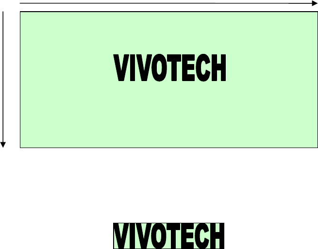
NEO Interface Developers Guide
389
Inverting the Color
Compared to a regular monochrome bitmap, the image used with ILM commands has inverted
color. White areas of the bitmap must be black and black areas white. To invert the color, each
bit of a bitmap image must be reversed by performing a NOT operation on each byte of image
data.
For example, suppose that 8 pixels were stored as 0x43 (0100 0011 in binary). This value must
be reversed with the logical NOT to become 0xBC (1011 1100 in binary). Thus, 0xBC on an LCD
matches 0x43 displayed on a PC monitor.
Image Cropping
Although message bitmaps can be sent at maximum screen size, cropping the images speeds the
download and uses less memory. Cropping MUST be done after all other processing of the bitmap
image. Other operations may be done in any order (as long as cropping is done last).
Cropping the image requires that you include the row number, column number, height and
width parameters in the ViVOpay header. The Column Number/Row Numbers define where the
upper-left corner of the bitmap is positioned. The Height and Width parameters determine the
area the bitmap takes up on the LCD screen.
For example, here is a 128x64 pixel bitmap:
Here is the same image with unnecessary white space cropped out. It is now 50x10 pixels:
Cropping must be expressed in byte boundaries instead of pixels. For example, suppose you
want to crop pixels 0 – 11 of a row of 128 pixels. Byte 0 (containing pixels 0-7) can be cropped
NEO Interface Developers Guide
390
but Byte 1 (containing pixels 8-15) cannot be cropped, since it contains bits of non-cropped data.
Thus, in this case, the cropping would begin at the Byte 1 (i.e., Column 1 boundary).
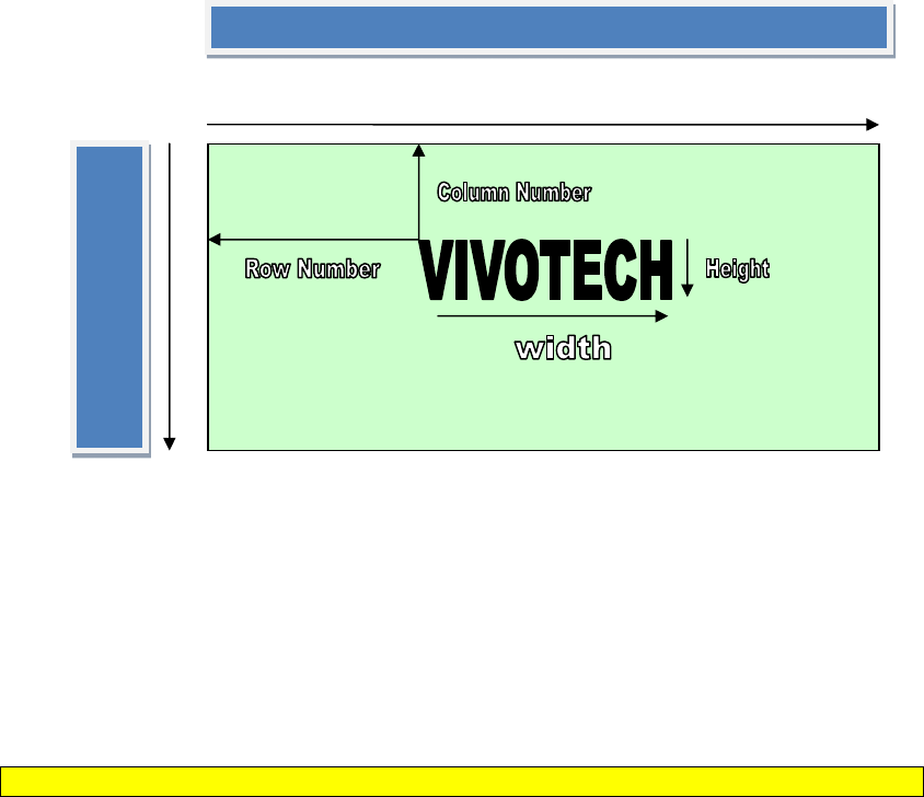
NEO Interface Developers Guide
391
The following diagram shows how the header parameters are derived.
The Row Number refers to the number of rows, each of which is a row of pixels. The Column
Number refers to a byte location. So Row varies from 0 to 63, and the Column varies from 0 to
15.
Example
The following is a simple example of a bitmap which measures 24x4 pixels (24 pixels per row, 4
rows). All bitmap values shown are arbitrary (and in hexadecimal).
Note: This example does NOT include image cropping.
ACTUAL BMP:
[14-byte BMP file header] + [40 byte DIB header] +
[Bitmap Data = (11 00 00 00) (22 00 01 00) (33 00 01 00) (44 00 00 00)]
First remove the headers.
[Bitmap Data = (11 00 00 00) (22 00 01 00) (33 00 01 00) (44 00 00 00)]
Then invert the image by swapping the rows. In this example, each row is 32 bits, i.e., 4 bytes
long. Row 1 is swapped with the last row (4), Row 2 is swapped with the next-to-last row (3) and
so on.
0
1
2
.
.
.
.
62
63
0 1
NEO Interface Developers Guide
392
[Bitmap Data = (44 00 00 00) (33 00 01 00) (22 00 01 00) (11 00 00 00)]
Next reverse the bits.
[Bitmap Data = (BB FF FF FF) (CC FF FE FF) (DD FF FE FF) (EE FF FF FF)]
Analyze the image. If the image needs to be cropped for white space reduction, do it now.
Calculate positioning parameters and generate the ILM header.
[12 byte ILM header] +
[Bitmap Data = [BB FF FF FF] [CC FF FE FF] [DD FF FE FF] [EE FF FF FF]]
This modified image data is now ready to be displayed or stored on the ViVOpay LCD.

NEO Interface Developers Guide
393
Appendix A.10: Default Configuration
ViVOpay readers are set to operate out of the box for many applications. This appendix
describes the default operating mode and default TLV data object values that have not been
previously covered.
Refer to the Configuration Tag Tables for default TLV values.
Communication Speed
The default baud rate for most units is 19200. The baud rate itself is a configurable parameter
that can be set as described in the Interface Developer's Guide. The ViVOpay readers can
communicate on any COM port specified by the integrators application. Handshaking is disabled
(8 N 1).
Please note, baud rate for the ViVOpay Vendi reader is 9600.
Polling Mode
The default configuration for the firmware is Auto Poll. While operating in Auto Poll, the reader
is constantly polling for contactless cards. When a card is presented to the field, reader
completes the data exchange. Transaction data is obtained by the POS via GET TRANSACTION
RESULT, READ FULL TRACK DATA, or a Burst Mode configuration. This poll mode is best suited
for contactless-magstripe data transactions (i.e. PayPass Mag Stripe & payWave MSD).
Auto Poll mode is not compatible with the EMEA User Interface configuration or M/Chip 3.0
applications. If you are using the EMEA UI or M/Chip 3.0, then you should configure the
polling mode to be “Poll on Demand”. Refer to the Set Poll Mode (01-01) command.
Burst Mode
While operating in Burst Mode, any time a valid contactless card is presented to the reader and
the transaction completes successfully, the Burst Mode Payload Packet is immediately
transmitted to the POS. The payload packet primarily consists of Track 1 and Track 2 data.
The default configuration for the firmware is Bust Mode, Auto-Off. When configured in this
fashion Burst Mode is fully active until receiving a transaction command (i.e. ACTIVATE
TRANSACTION, GET TRANSACTION RESULT, etc.) at which time Burst Mode is disabled until the
next power cycle.
Burst Mode is only valid for contactless applications returning magstripe Track 1 and Track 2
data, such as PayPass Magstripe & Visa payWave MSD.
To configure burst mode, refer to the Global Configuration Tags table, tag FFF7h.
The magstripe reader itself always operates in burst mode, regardless of the burst mode settings
defined in the EMV parameters, meaning that any swipe at the magstripe reader will result in a
payload packet immediately being sent across the serial interface.
Burst mode output from the magstripe reader can be disabled with the Burst mode parameter.
Refer to the Global Configuration Tags table, tag FFF7h.
RTC/LCD/Buzzer/LED Source
The ViVOpay readers are designed with flexibility in regards to the source of the Real Time
Clock (RTC), Liquid Crystal Display (LCD), Buzzer, and Light Emitting Diodes (LED). Each of these
components can be set to use a source internal or external to the ViVOpay unit. These

NEO Interface Developers Guide
394
components can also be disabled by setting the source to "none". As a default the source of each
of these components is set as follows:
RTC: Internal for units with an RTC. External for units without an RTC
LCD: Internal
Buzzer: Internal
LED: Internal
To configure the RTC/LCD/Buzzer/LED source, refer to the Set/Get Source for
RTC/LCD/Buzzer/LED (01-05) command.

NEO Interface Developers Guide
395
Default Message Index
The LCD message set applied by the ViVOpay unit depends on the User Interface (UI), tag 'FF F8'. As previously defined, the default UI is
ViVOpay, and when setting a new UI (Visa Wave or EMEA) the associated message index must be loaded.
The various UI message indexes are structured as follows.
Message
Index
Dot Matrix LCD Display Message
Indication ViVOtech
UI Scheme = '00'
VisaWave
UI Scheme = '02'
EMEA
UI Scheme = '03'
Language Line
0x00
WELCOME WELCOME WELCOME
ENG
L1:
L2:
" Welcome "
" "
" Welcome "
" "
" Welcome "
" "
FRA
L1:
L2:
" Bienvenue "
" "
" Bienvenue "
" "
" Bienvenue "
" "
ENG&FRA
L1:
L2:
" Welcome "
" Bienvenue "
" Welcome "
" Bienvenue "
" Welcome "
" Bienvenue "
0x01
TAP_OR_SWIPE_CARD
THANK_YOU
TAP_OR_SWIPE_CARD
ENG
L1:
L2:
" Please Tap Or "
" Swipe Card "
" Thank You "
" "
" Please Tap Or "
" Swipe Card "
FRA
L1:
L2:
" Présentez "
" carte SVP "
" Merci "
" "
" Présentez "
" carte SVP "
ENG&FRA
L1:
L2:
" Tap Or Swipe"
" Presentez Carte"
" Thank You "
" Merci "
"Tap Or Swipe "
" Presentez Carte"
0x02
NO_CARD
THANK_YOU
NO_CARD
ENG
L1:
L2:
" No Card "
" "
" Thank You "
" "
" No Card "
" "
FRA
L1:
L2:
" Aucune carte "
" "
" Merci "
" "
" Aucune carte "
" "
ENG&FRA
L1:
L2:
" No Card "
" Aucune carte "
" Thank You "
" Merci "
" No Card "
" Aucune carte "
0x03
PROCESSING
TRANSACTION_COMPLETED
NOT_CONNECTED
ENG
L1:
L2:
" Processing "
" "
" Transaction "
" Completed "
" Not "
" Connected "
FRA
L1:
" En cours "
" Transaction "
" Pas "

NEO Interface Developers Guide
396
L2:
" "
" Terminée "
" connecté "
ENG&FRA
L1:
L2:
" Processing "
" En Traitement "
"Transaction Done"
"Transaction Comp"
" Not Connected "
" Pas connecté "
0x04
THANK_YOU
USE_OTHER_VISA_CARD
CARD_READ_OK
ENG
L1:
L2:
" Thank You "
" "
" Please Use "
"Other VISA Card "
" Card Read OK "
" Remove Card "
FRA
L1:
L2:
" Merci "
" "
" Utilisez une "
"autre carte VISA"
" Lecture Carte OK "
"Retirez la carte"
ENG&FRA
L1:
L2:
" Thank You "
" Merci "
"Use Other Card "
"Autre carte VISA "
" Remove the card"
"Retirez la carte"
0x05
CARD_FAIL
SWIPE_CARD
CARD_FAIL
ENG
L1:
L2:
" Fail "
" "
"Use Alternative "
" Payment Method "
" Fail "
" "
FRA
L1:
L2:
" Échec "
" "
" Insérez ou "
" Passez la carte "
" Échec "
" "
ENG&FRA
L1:
L2:
" Card Failure "
" Échec Carte "
" Swipe Card "
"Passez la carte"
" Card Failure "
" Échec Carte "
0x06
AMOUNT
1_CARD
AMOUNT
ENG
L1:
L2:
" Amount: "
" "
" Present One "
" Card Only "
" Present Card: "
" "
FRA
L1:
L2:
" Montant: "
" "
" Présentez une "
" seule carte "
"Présentez carte:"
" "
ENG&FRA
L1:
L2:
"Amount/Montant: "
" "
" Present 1 Card "
"Présentez 1 Cart"
"Purchase/Achat: "
" "
0x07
BALANCE
INTERNATIONAL_CARD
BALANCE
ENG
L1:
L2:
" Balance: "
" "
" International "
" Card Only "
" Available: "
" "
FRA
L1:
L2:
" Solde: "
" "
" Internationale "
" Carte Seulement"
" Disponible: "
" "
ENG&FRA
L1:
L2:
" Balance/Solde: "
" "
" Card/Carte "
"International(e) "
" Available: "
" Disponible: "
0x08
USE_CHIP_N_PIN
TRY_AGAIN
SWIPE_CARD
ENG
L1:
L2:
" Use Chip "
" & PIN "
" Please "
" Try Again "
"Use Alternative "
" Payment Method "
FRA
L1:
L2:
" Utilisez "
" la puce "
" Ré-essayez "
" "
" Insérez ou "
"Passez la carte"
ENG&FRA
L1:
L2:
" Use Chip & PIN "
"Utilizer la puce"
"Please Try Again"
" Ré-essayez "
" Swipe Card "
"Passez la carte"
0x09
TRY_AGAIN
INTERNATIONAL_CARD
TRY_AGAIN
ENG
L1:
" Please "
" International "
" Try Again "

NEO Interface Developers Guide
397
L2:
" Try Again "
" Card Only "
" "
FRA
L1:
L2:
" Ré-essayez "
" "
" Internationale "
" Carte Seulement"
" Ré-essayez "
" "
ENG&FRA
L1:
L2:
"Please Try Again"
" Ré-essayez "
" Card/Carte "
"International(e) "
" Try Again "
" Ré-essayez "
0x0A
1_CARD
SIGN_RECEIPT
1_CARD
ENG
L1:
L2:
" Present One "
" Card Only "
" Please "
" Sign Receipt "
" Present One "
" Card Only "
FRA
L1:
L2:
" Présentez une "
" seule carte "
" Signez le recu "
" "
" Présentez une "
" seule carte "
ENG&FRA
L1:
L2:
" Present 1 Card "
"Présentez 1 Cart"
" Sign Receipt "
" Signez le recu "
"Present 1 Card "
"Présentez 1 Cart"
0x0B
WAIT
SIGN_RECEIPT
WAIT
ENG
L1:
L2:
" Please Wait "
" "
" Please "
" Sign Receipt "
" Please Wait "
" "
FRA
L1:
L2:
" Attendez "
" "
"" Signez le recu "
" "
" Attendez "
" "
ENG&FRA
L1:
L2:
" Please Wait "
" Attendez "
" Sign Receipt "
" Signez le recu "
" Please Wait "
" Attendez "
0x0C
REMOVE_CARD
ENTER_PIN
REMOVE_CARD
ENG
L1:
L2:
" Please "
" Remove Card "
" Please "
" Enter PIN "
" Please "
" Remove Card "
FRA
L1:
L2:
" Enlevez "
" carte SVP "
"Entrez votre "
" code "
" Enlevez "
" carte SVP "
ENG&FRA
L1:
L2:
" Remove Card "
" Retirez la Carte"
"PIN EntryRequire"
"Code exige"
" Remove Card "
" Retirez la Carte"
0x0D
APPROVED
AVAIL_OFFLINE_AMOUNT
APPROVED
ENG
L1:
L2:
" Approved "
" "
" Offline Amount "
" "
" Approved "
" "
FRA
L1:
L2:
" Approuvé "
" "
" Montant "
" hors ligne "
" Approuvé "
" "
ENG&FRA
L1:
L2:
" Approved "
" Approuvé "
" Offline Amount "
" Mt hors ligne "
" Approved "
" Approuvé "
0x0E
NOT_AUTHORIZED
ENTER_PIN
DECLINED
ENG
L1:
L2:
" Not "
" Authorized "
" Please "
" Enter PIN "
" Declined "
" "
FRA
L1:
L2:
" Non "
" autorisé "
"Entrez votre "
" code "
" Refusé "
" "
ENG&FRA
L1:
L2:
" Not Authorized "
" Non autorisé "
"PIN EntryRequire"
"Code exige"
" Declined "
" Refusé "

NEO Interface Developers Guide
398
0x0F
DECLINED
SIGNATURE_REQUIRED
Reserved MSG16
ENG
L1:
L2:
" Declined "
" "
" Signature "
" Required "
" "
" "
FRA
L1:
L2:
" Refusé "
" "
" Signature "
" Requise "
" "
" "
ENG&FRA
L1:
L2:
" Declined "
" Refusé "
"SignatureRequire"
"Signature Requise"6
" "
" "
0x10
TERMINATED
Reserved MSG17
Reserved MSG17
ENG
L1:
L2:
" Terminated "
" "
" "
" "
" "
" "
FRA
L1:
L2:
" Terminé "
" "
" "
" "
" "
" "
ENG&FRA
L1:
L2:
" Cannot Process "
" Ne Peut Procés "
" "
" "
" "
" "
0x11
TRY_OTHER_INTERFACE
TAP_OR_SWIPE_CARD
TRY_OTHER_INTERFACE
ENG
L1:
L2:
" Try Other "
" Interface "
" Present Card "
" "
" Try Other "
" Interface "
FRA
L1:
L2:
"Autre Interface "
" "
" Présentez"
"votre carte"
"Autre Interface "
" "
ENG&FRA
L1:
L2:
"AnotherInterface"
"Autre Interface "
" Purchase/Achat "
" "
"AnotherInterface"
"Autre Interface "
0x12
USE_OTHER_CARD
REMOVE_CARD
USE_OTHER_CARD
ENG
L1:
L2:
" Use Other Card "
" "
" Please "
" Remove Card "
" Use Other Card "
" "
FRA
L1:
L2:
" Use Other Card "
" "
" Enlevez "
"votre carte SVP "
" Use Other Card "
" "
ENG&FRA
L1:
L2:
" Use Other Card "
" "
" Remove Card "
"Retirez la Carte"
" Use Other Card "
" "
0x13
TIMEOUT
PROCESSING
TIMEOUT
ENG
L1:
L2:
" Time Out "
" "
" Processing "
" "
" Time Out "
" "
FRA
L1:
L2:
" Time Out "
" "
" En cours "
" "
" Time Out "
" "
ENG&FRA
L1:
L2:
" Time Out "
" "
" Processing "
" En Traitement "
" Time Out "
" "
0x14
CANCEL
DECLINED
CANCEL
ENG
L1:
" Cancel "
" Declined "
" Cancel "
6 String length over 16 characters, LCD displays first 16 characters only.

NEO Interface Developers Guide
399
L2:
" "
" "
" "
FRA
L1:
L2:
" Annuler "
" "
" Refusé "
" "
" Annuler "
" "
ENG&FRA
L1:
L2:
" Cancel "
" Annuler "
" Declined "
" Refusé "
" Cancel "
" Annuler "
0x15
ONLINE
TERMINATED
ONLINE
ENG
L1:
L2:
" Authorizing "
" "
" Terminated "
" "
" Authorizing "
" "
FRA
L1:
L2:
" En Traitement "
" "
" Terminé "
" "
" En Traitement "
" "
ENG&FRA
L1:
L2:
" Processing "
" En Traitement "
" Cannot Process "
" Ne Peut Procés "
" Processing "
" En Traitement "
0x16
SEE_PHONE
SEE_PHONE
SEE_PHONE
ENG
L1:
L2:
" See Phone "
" "
" See Phone "
" "
" See Phone "
" "
FRA
L1:
L2:
"Entrée d'un code"
" "
"Entrée d'un code"
" "
"Entrée d'un code"
" "
ENG&FRA
L1:
L2:
" PassCode Entry "
"Entrée d'un code"
" PassCode Entry "
"Entrée d'un code"
" PassCode Entry "
"Entrée d'un code"
0x17
NOT_ACCEPTED
NOT_ACCEPTED
NOT_ACCEPTED
ENG
L1:
L2:
" Not Accepted "
" "
" Not Accepted "
" "
" Not Accepted "
" "
FRA
L1:
L2:
" Pas accepté "
" "
" Pas accepté "
" "
" Pas accepté "
" "
ENG&FRA
L1:
L2:
" Not Accepted "
" Pas accepté "
" Not Accepted "
" Pas accepté "
" Not Accepted "
" Pas accepté "
0x18
INSERT_CARD
INSERT_CARD
INSERT_CARD
ENG
L1:
L2:
" Insert Card "
" "
" Insert Card "
" "
" Insert Card "
" "
FRA
L1:
L2:
"Insérez la carte"
" "
"Insérez la carte"
" "
"Insérez la carte"
" "
ENG&FRA
L1:
L2:
" Insert Card "
"Insérez la carte"
" Insert Card "
"Insérez la carte"
" Insert Card "
"Insérez la carte"
0x19
REFUND
REFUND
REFUND
ENG
L1:
L2:
" Refund "
" "
" Refund "
" "
" Refund "
" "
FRA
L1:
L2:
" Remboursement "
" "
" Remboursement "
" "
" Remboursement "
" "
ENG&FRA
L1:
L2:
"Refund"
"Remboursement "
"Refund"
" Remboursement "
"Refund"
"Remboursement"

NEO Interface Developers Guide
400
0x1A
STOP
STOP
STOP
ENG
L1:
L2:
" STOP "
" "
" STOP "
" "
" STOP "
" "
FRA
L1:
L2:
" Arrêtez "
" "
" Arrêtez "
" "
" Arrêtez "
" "
ENG&FRA
L1:
L2:
" STOP "
" Arrêtez "
" STOP "
" Arrêtez "
" STOP "
" Arrêtez "

NEO Interface Developers Guide
401
Appendix A.11: Enhanced Encrypted MSR Data Output Format
Definitive information on this format can be found in ID TECH document #80000403-001, Enhanced
Encrypted MSR Data Output Format. Request a copy from your ID TECH representative.
Note that data conforming to this standard will (as with EMV data) be framed within a ViVOtech2
standard header or "preamble" (consisting of 14 bytes: ViVOtech2\0, command byte, response byte,
two-byte length), at the beginning, plus a two-byte CRC at the end:
<PREAMBLE><Attribution Byte><MSR TLV>< Point of Service (POS) Entry Mode TLV><
ViVOPay Group TLV>< Encrypt Information TLV><CRC>
The 24 data fields can be parsed as shown below. Note that the first field is STX (0x02) and the last
field is ETX (0x03). It's essential to inspect the flag bits in fields 8 and 9 to determine which of several
optional fields are present, and also to determine whether encrypted fields are present (in which case,
padding must be taken into account; see detailed description hereunder).
The CRC is calculated using ALL upstream bytes of the data output (that is, using the preamble as well
as the 24 fields of data).
MSR DATA OUTPUT FORMAT
Field #
Length
in Bytes
Optional Field Name
1
1
STX
2
2
Data Length
3
1
Card Encode Type
4
1
Track Status
5
1
Track1 data length
6
1
Track2 data length
7
1
Track3 data length
8
1
Clear/mask data sent status
9
1
Encrypted/Hash data sent status
10
Variable
Y
Track1 clear/mask data
11
Variable
Y
Track2 clear/mask data
12
Variable
Y
Track3 clear/mask data
13
Variable
Y
Track1 encrypted data
14
Variable
Y
Track2 encrypted data
15
Variable
Y
Track3 encrypted data
16
8
Y
Session ID (Security level 4 only)
17
20
Y
Track1 hashed (if encrypted)
18
20
Y
Track2 hashed (if encrypted)
19
20
Y
Track3 hashed (if encrypted)
20
10
Y
Reader Serial Number
21
10
Y
KSN
22
1
LRC (XOR of all bytes from Field 3 to 21 inclusive)
23
1
CheckSum (sum of all bytes from Field 3 to 21
inclusive; take the low 8 bits of sum, only)
24
1
ETX
The presence/absence of Optional fields can be determined by inspecting flag bits in fields 8 and 9.
Field 1: STX

NEO Interface Developers Guide
402
Start of Text. 0x02.
Field 2: Data Length
Data Length low byte comes first if it is output format 1, then Data Length high byte.
Data Length high byte comes first if it is output format 2,then Data Length low byte. (Output format 2
applies only to insert readers, not contactless.)
Field 3: Card Encode Type:
Value Encode Type Description
80 ISO 7813/ISO 4909/ABA format
81 AAMVA format
83 Other
84 Raw; un-decoded format. All tracks are encrypted and no mask data is sent. No track indicator
‘01’, ‘02’ or ‘03’ in front of each track.
85 JIS II Only supported in some products
86 JIS I Only supported in some products
87 JIS II SecureKey and Secure MIR
Field 4: Track Status
MSR sampling and decode status
MSB LSB
0
0
B5
B4
B3
B2
B1
B0
B0 1: Track 1 decode success (0: Track 1 decode fail)
B1 1: Track 2 decode success (0: Track 2 decode fail)
B2 1: Track 3 decode success (0: Track 3 decode fail)
B3 1: Track 1 sampling data exists (0: Track 1 sampling data does not exist)
B4 1: Track 2 sampling data exists (0: Track 2 sampling data does not exist)
B5 1: Track 3 sampling data exists (0: Track 3 sampling data does not exist)
B6 0—reserved for future
B7 0—reserved for future
Field 5: Track1 data length
Field 6: Track2 data length
Field 7: Track3 data length
These one-byte values are the length of the actual Track data. It indicates the number of bytes
in the Track masked data field. It should be used to separate Track 1, Track 2 and Track 3 data
after decrypting Track encrypted data field.
For ISO 7813 and ISO 4909 compliant Financial Transaction Cards:
Track 1 maximum length is 79 alphanumeric characters.
Track 2 maximum length is 40 numeric digits.
Track 3 maximum length is 107 numeric digits.
Field 8: Clear/mask data sent status byte and bit 0 is the least significant bit.
Bit 0: 1--- if Track1 clear/mask data present
Bit 1: 1--- if Track2 clear/mask data present
Bit 2: 1--- if Track3 clear/mask data present
Bit 3: 1— if fixed key; 0 DUKPT Key Management
Fixed key is only supported in some products
Bit 4: 0- TDES; 1 - AES
Bit 5: 0- No requirement to use IC (1st digit in Service Code is different from 2 or 6; 1- Use IC
where feasible (1st digit in Service Code is 2 or 6)
Bit 6: 1-- Pin Encryption Key; 0 – Data Encryption Key
Refer ANSI X9.24 2009 Page 56 for details.
Bit7: 1 – Serial # present; 0- not present
NEO Interface Developers Guide
403
Field 9: Encrypted data sent status
Bit 0: if 1—track1 encrypted data present
Bit 1: if 1—track2 encrypted data present
Bit 2: if 1—track3 encrypted data present
Bit 3: if 1—track1 hash data present
Bit 4: if 1—track2 hash data present
Bit 5: if 1—track3 hash data present
Bit 6: if 1—session ID present
Bit 7: if 1—KSN present
Fields 13, 14, & 15: These fields are the encrypted Track data, using either TDES-CBC or AES-CBC with
initial vector of 0. If the original data is not a multiple of 8 bytes for TDES or a multiple of 16 bytes
for AES, the reader pads the original data with trailing zeros. Hence, the length of the encrypted data
could be greater than the length of the original (unencrypted) data.
The key management scheme is DUKPT. For DUKPT, the key used for encrypting data is called the Data
Key. Data Key is generated by first taking the DUKPT Derived Key XOR’d with
0000000000FF00000000000000FF0000 to get the resulting intermediate variant key. The left side of the
intermediate variant key is then TDES encrypted with the entire 16-byte variant as the key. After the
same steps are preformed for the right side of the key, combine the two key parts to create the Data
Key.
Note that Tracks 1, 2 and 3 of card data are encrypted separately. In order to get the number of bytes
for each track’s encrypted data field, the field length is always a multiple of 8 bytes for TDES or
multiple of 16 bytes for AES. (This value will be zero if there was no data on a track.) Once the
encrypted data has been decrypted, all padding bytes need to be removed. The number of bytes of
decoded track 1, 2, or 3 data is indicated by the track 1, 2, or 3 unencrypted length field (Fields 5, 6
and 7, respectively).
Field 16: Session ID (Security level 4 only; not applicable to Kiosk II/III nor Vendi)
Field 17: Track1 hashed (if encrypted and hash track1 allowed)
Field 18: Track2 hashed (if encrypted and hash track2 allowed)
Field 19: Track3 hashed (if encrypted and hash track3 allowed)
SHA-1 is used for non-SRED products and 20 zeroes are used for SRED products. Refer to applicable
product manual for details.
SHA-1 is used to generate hashed data for track 1 to track 3 unencrypted data. It is 20 bytes long for
each track. This is provided with two purposes in mind: One is for the host to ensure data integrity by
comparing this field with a SHA-1 hash of the decrypted Track data, as a safeguard against unexpected
noise in data transmission. The other purpose is to enable the host to store a token of card data for
future use without keeping the sensitive card-holder data itself. This token may be used for comparison
with the stored hash data to determine if they are from the same card.
Field 20: Reader Serial Number (optional); always 10 bytes (pad with leading 0x30 if <10 digits)
Field 21: KSN (DUKPT only)
Field 22: CheckLRC
XOR of all data from Card Encode Type to end of KSN for Output Format 1 (contactless); XOR of all data
before CheckLRC for Output Format 2 (insert readers).
Field 23: CheckSum Field Omitted if Output Format 2 (insert readers).
Sum
Bottom 8 bits of SUM of all bytes values from Card Encode Type to end of KSN.
Field 24: ETX
NEO Interface Developers Guide
404
End of Text (0x03).
NEO Interface Developers Guide
405
Appendix A.12: Encrypted Data Format, TLV-Based
The information below is based, in part, on ID TECH P/N 80000502-001, ID Tech Encrypted Data Output
Formats. Consult the latest version of that document for more information.
For data passed in Tag/Length/Value (TLV) format, the Length value will be used to signal encryption
and/or masking of the Value being received. If the bottom 5 bits are ON (that is, if Byte & 0x1F == 0x1F),
then the next byte is also part of the tag. Likewise, if the most significant bit is ON (that is, if Byte & 0x80
== 0x80), then the next byte is also part of the tag.
Examples:
8F 02 03 04: Tag = 8F
9F 02 03 04: Tag = 9F02
BF A2 92 82: Tag = BFA292
Length
If the most significant bit (b7) of length is OFF, then that byte is, itself, the data length of the data
to follow.
If the most significant bit (b7) is ON, then the lower nibble specifies the number of following bytes
that contain the length of the data to follow.
Standard TLV Examples
6F 12 13 14 15 . . .: Tag is 6F, Length is 12, Data starts at 13
9F 20 81 82 83 84 . . .: Tag is 9F20, Length is the 1 byte after 81, which is 0x82, data starts at 83
DF 81 01 82 01 02 03 . . .: Tag is DF8101, Length is the 2 bytes after 82, which is 0x0102, data
starts at 03
Using Length Byte to Flag Mask and Encryption (IDTech Enhanced TLV)
The Length bit shall be used when data is masked or encrypted:
Bit 7 will be set to 1
Bit 6 will be set to 1 if there is encryption
Bit 5 will be set to 1 if there is a mask
Bits 0-4 signify the amount of bytes that follow specifying the data length
IDTech Enhanced TLV Examples
6F 12 13 14 15 . . .: Tag is 6F, Length is 12, Data starts at 13, no mask/enc.
9F 20 C1 82 83 84 . . .: Tag is 9F20, Length is the 1 byte after C1, which is 0x82, data is
encrypted, data starts at 83
DF 81 01 A2 01 02 03 . . .: Tag is DF8101, Length is the 2 bytes after A2, which is 0x0102, data
is masked, data starts at 03
Using Length Byte to Flag Mask and Encryption (IDTech Enhanced TLV):
The Length bit shall be used when data is masked or encrypted:
Bit 7 will be set to 1
Bit 6 will be set to 1 if there is encryption
Bit 5 will be set to 1 if there is a mask
Bits 0-4 signify the amount of bytes that follow specifying the data length
IDTech Enhanced TLV Examples:
6F 12 13 14 15 . . .: Tag is 6F, Length is 12, Data starts at 13, no mask/enc.

NEO Interface Developers Guide
406
9F 20 C1 82 83 84 . . .: Tag is 9F20, Length is the 1 byte after C1, which is 0x82, data is
encrypted, data starts at 83
DF 81 01 A2 01 02 03 . . .: Tag is DF8101, Length is the 2 bytes after A2, which is 0x0102, data
is masked, data starts at 03
Encrypted/Masked TAG Note
The following table shows the tags that will be encrypted and/or masked:
Tag Data Object
Note Plaintext
Mask and format
Encryption and
format
5A Application
PAN
None Mask
5A A1 Len
<value>
This Value must
be Masked
according to
PreCtlNum and
PostCtlNum, then
output.
Encryption
5A C1 Len
<value>
9F1F Track 1
Discretionary
Data
None None Encryption
9F 1F Cx Len
<value>
9F20 Track 2
Discretionary
Data
None None Encryption
9F 20 Cx Len
<value>
57 Track 2
Equivalent
Data
None None Encryption
57 Cx Len
<value>
56 Track 1 Data
1. MasterCard-Paypass
(MagStripe) defines it
2. DiscoverZip defines it.
3. Visa MSD – Do not Define.
4. Amex – Do not Define.
5. PBOC– Do not Define.
None None Encryption
56 Cx Len
<value>
5F20 Cardholder
Name
Full
Plaintext
None None
5F24 Expire Date Full
Plaintext
None None
5F30 Service Code
Full
Plaintext
None None
9F6B Track 2 Data
1. MasterCard-Paypass
(MagStripe) defines it
2. DiscoverZip – Do not Define.
None None Encryption
9F 6B Cx Len
<value>

NEO Interface Developers Guide
407
3. Visa MSD –Define it for ‘Card
CVM Limit’. Now Do Not Encrypt
it in Visa MSD.
4. Amex – Do not Define.
5. PBOC–Define it for ‘Card CVM
Limit’. Now Do Not Encrypt it in
PBOC.
If it is used for Track2 Data. The
value need be encrypted, then
Output.
FFEE13
Track 1 Data
1. DiscoverZip Need Use it.
2. Visa MSD Need Use it.
3. Amex Need Use it.
4. PBOC Need Use it.
None None Encryption
FF EE 13 Cx Len
<value>
FFEE14
Track 2 Data
1. DiscoverZip Need Use it.
2. Visa MSD Need Use it.
3. Amex Need Use it.
4. PBOC Need Use it.
None None Encryption
FF EE 13 Cx Len
<value>
Tag Data Object Note Plaintext Mask and format Encryption and format
DF812A DD Card Track 1 None None Encryption
DF 81 2A Cx Len <value>
DF812B DD Card Track 2 None None Encryption
DF 81 2B Cx Len <value>
DF31 DD Card Track 1 None None Encryption
DF 31 Cx Len <value>
DF32 DD Card Track 2 None None Encryption
DF 32 Cx Len <value>
Note:
1. DiscoverZip has 56 Tag (Track 1 Data) and Formal Track1 & 2 Data (No Tags). So DiscoverZip will have 56, FF EE 13, FF
EE 14 (3 Tags) later.
2. Visa MSD, Amex, PBOC will have FF EE 13, FF EE 14 (2 Tags for Formal Track 1 & 2 Data) later.
NEO Interface Developers Guide
408
Track 1 (Tag 56) & 2 (Tag 9F6B) Mask Configuration Note
Masked Area
The data format of each masked track is ASCII or Hex. The clear data includes start and end sentinels,
separators, first N, last M digits of the PAN, card holder name, expiry date and service code. The rest of
the characters should be masked using mask character.
1. Set PrePANClrData (N)
1 byte parameter, range is 0~6, default value 4
2. Set PostPANClrData (M)
1 byte parameter, range is 0~4, default value 4
3. Set DisplayExpirationDataID
1 byte parameter, value is 0x30 (Mask) / 0x31 (Not Mask), default value 0x31
4. Set MaskCharID (Mask Character) for Ascii Code Track Data
1 byte parameter, range is 0x20~0x7E, default value 0x2A (*)
5. Set MaskCharID (Mask Character) for Hex Code Track Data
1 nibble parameter sent as byte value, range is 0x0A~0x0F, default value 0x0C
6. Set ExpireDateOutputOpt
1 byte parameter, value is 0x30 (Output Masked for Tag 57 and Only Output EncryptedValue for Tag
5F24) / 0x31 (Output Plaintext), default value 0x31
Example:
ASCII Pan clear data: “012345678912”
Pre-PAN clear data characters: 5
Post-PAN clear data characters: 3
Mask Character = “*”
Masked Value = “01234****912”
Hex value clear data: 0x012345678912
Pre-PAN clear data characters: 5
Post-PAN clear data characters: 3
Mask Character = 0x0C
Masked Value = 0x01234CCCC912
Other Tag Value Mask Configuration Note
1. Set PrePANClrData (N)
1 byte parameter, range is 0~6, default value 4
2. Set PostPANClrData (M)
1 byte parameter, range is 0~4, default value 4
3. Set MaskCharID (Mask Character) for Ascii Code Value
1 byte parameter, range is 0x20~0x7E, default value 0x2A (*)
4. Set MaskCharID (Mask Character) for Hex Code Value
1 byte parameter, range is 0x0A~0x0F, default value 0x0C
NEO Interface Developers Guide
409
5. In 57 Tag Value, the data before 0xDx is PAN data, it need be Masked as Tag 5A Value.
5. In 57 Tag Value, in the data 0xDy ym ms xz, yy mm is expiry date, and sxz is service code, they Need
Not be Masked.
6. In 57 Tag Value, the data after 0xDy ym ms xz are Other data, they need be Masked.
Detailed – TLV Encrypted Response Format
Example of Encrypting a TLV
Example 1
1. Plaintext 5A TLV data (5A 08 47 61 73 90 01 01 00 10)
2. Encrypt this TLV data (5A 08 47 61 73 90 01 01 00 10) to be 16 bytes Encrypted Data (XX XX XX XX
XX XX XX XX XX XX XX XX XX XX XX XX):
For TDES mode: The Length should be multiple of 8. If it was not multiple of 8, unit should zero
padded y bytes data follow automatically (the length +y should be multiple of 8).
For AES mode: The Length should be multiple of 16. If it was not multiple of 16, unit should zero
padded y bytes data follow automatically (the length +y should be multiple of 16).
3. Re-Create New TLV data for Mask:
TAG is 5A
Length is A1 08:
A1 – Bit 7 is 1 note followed data length bytes. Bit 5 is 1 note data is Masked. Bit 0~4 (1) data
note followed n bytes (1 byte) data length.
08 – followed 8 bytes data
Data is 47 61 CC CC CC CC 00 10 (0x0C is Mask Data)
4. Re-Create New TLV data for Encryption:
TAG is 5A
Length is C1 10:
C1 – Bit 7 is 1 note followed data length bytes. Bit 6 is 1 note data is Encrypted. Bit 0~4 (1) data
note followed n bytes (1 byte) data length.
10 – followed 16 bytes data
Data is XX XX XX XX XX XX XX XX XX XX XX XX XX XX XX XX
Example 2
1. Plaintext 57 TLV data (57 11 47 61 73 90 01 01 00 10 D1 51 22 01 17 58 98 93 89)
2. Encrypt this TLV data (57 11 47 61 73 90 01 01 00 10 D1 51 22 01 17 58 98 93 89) to be 24 (TDES
mode) or 32 bytes (AES mode) Encrypted Data:
For TDES mode: The Length should be multiple of 8. If it was not multiple of 8, unit should zero
padded y bytes data follow automatically (the length +y should be multiple of 8).
For AES mode: The Length should be multiple of 16. If it was not multiple of 16, unit should zero
padded y bytes data follow automatically (the length +y should be multiple of 16).
NEO Interface Developers Guide
410
3. Re-Create New TLV data for Mask:
TAG is 57
Length is A1 11:
A1 – Bit 7 is 1 note followed data length bytes. Bit 5 is 1 note data is Masked. Bit 0~4 (1) data
note followed n bytes (1 byte) data length.
11 – followed 17 bytes data
If ExpireDataOutputOpt was set “Output Plaintext”, expiry date and service code all Need Not be
Masked. Data is 47 61 CC CC CC CC 00 10 D1 51 22 01 CC CC CC CC CC (0x0C is Mask Data):
47 61 73 90 01 01 00 10 is PAN, it Need be Masked same as 5A Tag Value
In D1 51 22 01, 1 51 2 is expiry date (2015year, December), 2 01 is service code, they all Need
Not be Masked.
Followed them all Need be Masked.
If ExpireDataOutputOpt was set “Output Plaintext”, expiry date and service code all Need Not be
Masked. Data is 47 61 CC CC CC CC 00 10 DC CC C2 01 CC CC CC CC CC (0x0C is Mask Data):
47 61 73 90 01 01 00 10 is PAN, it Need be Masked same as 5A Tag Value
In D1 51 22 01, 1 51 2 is expiry date (2015year, December) and Need be Masked, 2 01 is service
code and it Need Not be Masked.
Followed them all Need be Masked.
4. Re-Create New TLV data for Encryption (TDES mode):
TAG is 57
Length is C1 18:
C1 – Bit 7 is 1 note followed data length bytes. Bit 6 is 1 note data is Encrypted. Bit 0~4 (1) data
note followed n bytes (1 byte) data length.
18 – followed 24 bytes data
Data is XX XX XX XX XX XX XX XX XX XX XX XX XX XX XX XX XX XX XX XX XX XX XX XX
Example 3
1. Plaintext 9F 20 TLV data (9F 20 05 01 94 60 02 7F)
2. Encrypt this TLV data (9F 20 05 01 94 60 02 7F) to be 8 (TDES mode) or 16 bytes (AES mode)
Encrypted Data:
For TDES mode: The Length should be multiple of 8. If it was not multiple of 8, unit should zero
padded y bytes data follow automatically (the length +y should be multiple of 8).
For AES mode: The Length should be multiple of 16. If it was not multiple of 16, unit should zero
padded y bytes data follow automatically (the length +y should be multiple of 16).
3. Need Not Mask:
4. Re-Create New TLV data for Encryption (TDES mode):
TAG is 9F 20
Length is C1 08:
C1 – Bit 7 is 1 note followed data length bytes. Bit 6 is 1 note data is Encrypted. Bit 0~4 (1) data
note followed n bytes (1 byte) data length.
08 – followed 8 bytes data
Data is XX XX XX XX XX XX XX XX
Example 4
If all TLVs are same level.
NEO Interface Developers Guide
411
Raw data: 57 11 47 61 73 90 01 01 00 10 D1 51 22 01 17 58 98 93 89 5A 08 47 61 73 90 01 01 00 10 84
07 A0 00 00 00 03 10 10 9F 20 05 01 94 60 02 7F
New data: 57 A1 11 47 61 CC CC CC CC 00 10 D1 51 22 01 CC CC CC CC CC 57 C1 18 XX XX XX XX
XX XX XX XX XX XX XX XX XX XX XX XX XX XX XX XX XX XX XX XX 5A A1 08 47 61 CC CC CC CC
00 10 5A C1 10 XX XX XX XX XX XX XX XX XX XX XX XX XX XX XX XX 84 07 A0 00 00 00 03 10 10
9F 20 C1 08 XX XX XX XX XX XX XX XX
If all TLVs are not same level (PayPass application list Record).
Raw Data:
<FF 81 06 (Tag00)> <82 01 70 (Len00)> <TLV10> <TLV11>
<FF 81 01 (Tag12)> <7F (Len12)> <TLV20> <TLV21> 57 11 47 61 73 90 01 01 00 10 D1 51 22 01 17
58 98 93 89 5A 08 47 61 73 90 01 01 00 10 84 07 A0 00 00 00 03 10 10 9F 20 05 01 94 60 02 7F <
TLV23 > … <TLV2n>
<FF 81 01 (Tag13)> <7F (Len13)> <TLV20> <TLV21> 57 11 47 61 73 90 01 01 00 10 D1 51 22 01 17
58 98 93 89 5A 08 47 61 73 90 01 01 00 10 84 07 A0 00 00 00 03 10 10 9F 20 05 01 94 60 02 7F <
TLV23 > … <TLV2n>
<TLV14> … <TLV1n>
<FF 81 05 (Tag01)> <60 (Len01)> <TLV10> <TLV11> 57 11 47 61 73 90 01 01 00 10 D1 51 22 01 17 58
98 93 89 5A 08 47 61 73 90 01 01 00 10 84 07 A0 00 00 00 03 10 10 9F 20 05 01 94 60 02 7F <TLV13>
<TLV14> …
New data:
<FF 81 06 (Tag00)> <82 01 D5 (Len00)> <TLV10> <TLV11>
<FF 81 01 (Tag12)> <81 B0 (Len12)> <TLV20> <TLV21> 57 A1 11 47 61 CC CC CC CC 00 10 D1 51
22 01 CC CC CC CC CC 57 C1 18 XX XX XX XX XX XX XX XX XX XX XX XX XX XX XX XX XX XX XX
XX XX XX XX XX 5A A1 08 47 61 CC CC CC CC 00 10 5A C1 10 XX XX XX XX XX XX XX XX XX XX
XX XX XX XX XX XX 84 07 A0 00 00 00 03 10 10 9F 20 C1 08 XX XX XX XX XX XX XX XX <
TLV23 > … <TLV2n>
<FF 81 01 (Tag13)> <81 B0 (Len13)> <TLV20> <TLV21> 57 A1 11 47 61 CC CC CC CC 00 10 D1 51
22 01 CC CC CC CC CC 57 C1 18 XX XX XX XX XX XX XX XX XX XX XX XX XX XX XX XX XX XX XX
XX XX XX XX XX 5A A1 08 47 61 CC CC CC CC 00 10 5A C1 10 XX XX XX XX XX XX XX XX XX XX
XX XX XX XX XX XX 84 07 A0 00 00 00 03 10 10 9F 20 C1 08 XX XX XX XX XX XX XX XX <TLV24> …
<TLV2n>
<TLV14> … <TLV1n>
<FF 81 05 (Tag01)> <91 (Len01)> <TLV10> <TLV11> 57 A1 11 47 61 CC CC CC CC 00 10 D1 51 22 01
CC CC CC CC CC 57 C1 18 XX XX XX XX XX XX XX XX XX XX XX XX XX XX XX XX XX XX XX XX XX
XX XX XX 5A A1 08 47 61 CC CC CC CC 00 10 5A C1 10 XX XX XX XX XX XX XX XX XX XX XX XX
XX XX XX XX 84 07 A0 00 00 00 03 10 10 9F 20 C1 08 XX XX XX XX XX XX XX XX <TLV14>
<TLV15> …
Command Format
L2 commands do not carry sensitive data, hence the command can be plaintext.
Response Formats
KSN will be TLV format
1. 3 bytes KSN Tag – DF EE 12 (FFEE12 is reserved for existing contactless products – it will later
be replaced with DFEE12.)
2. 1 byte Len – 0A
NEO Interface Developers Guide
412
3. 10 bytes KSN
Contact L2 Response Format
06 + <Transaction Result > <Attribution> [<TLV>]
Where:
1. Transaction Result: 2 bytes (Approve, Decline, Other)
2. Attribution: 1 Byte
BIT0 – Card Type: 0 – Contact Card
BIT2,1 – Encryption Mode: 00 – TDES Mode, 01 – AES Mode
BIT3 – Card Type: 0 – Contact/Contactless Card. 1 – MSR. (For ViVOpay IDG)
BIT6~4 – Reserved
BIT7 – Encryption Status: 0 – Encryption OFF. 1 – Encryption ON. (For ViVOpay IDG)
3. <TLV> is optional only if transaction was Approved or Declined
<TLV> will include KSN as first tag (DFEE12) if new or changed since last KSN value.
Encryption (bit 6) and Masking (bit5) flags will be utilized as appropriate in the Length component of
the TLV element
Contactless L2 Response Format
06 + <Status Code > <Error Code >< Attribution > [<TLV>]
Where:
1. Status Code: 1 Byte. The usage is the same as in KioskII/KioskIII project and are used to specify if
transaction was approved or declined.
2. Error Code: 1 Byte. The usage is the same as in KioskII/KioskIII project and are used to specify if
transaction was approved or declined.
3. Attribution: 1 Byte
BIT0 – Card Type: 1 – Contactless Card
BIT2,1 – Encryption Mode: 00 – TDES Mode, 01 – AES Mode
BIT3 – Card Type: 0 – Contact/Contactless Card. 1 – MSR. (For ViVOpay IDG)
BIT6~4 – Reserved
BIT7 – Encryption Status: 0 – Encryption OFF. 1 – Encryption ON. (For ViVOpay IDG)
4. <TLV> is optional only if transaction was Approved or Declined
<TLV> will include KSN as first tag (Tag should be DFEE12, FFEE12 is reserved for existed
contactless products – Later it should be replaced with DFEE12.) if new or changed since last
KSN value.
Encryption (bit 6) and Masking (bit5) flags will be utilized as appropriate in the Length component of
the TLV element
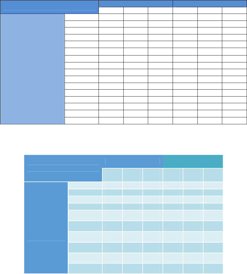
NEO Interface Developers Guide
413
Appendix A.13: Enhanced Encrypted MSR Data Output When
Encryption is Turned On with C7-38 Command
Enhanced Encrypted MSR Data Output Format for Bank Card
When the C7-38 command is used, the parameter you supply (first column) will determine what kind of
output occurs (remaining columns). For example, a parameter value of 0x00 results in masked Track 1
and Track 2 data, cleartext data for Track 3, and encrypted and hashed (E+H) data for Tracks 1 & 2.
C7-38 Parameter Value:
Clear / Mask Data
Encrypted / Hash Data
Track 3
Track 2
Track 1
Track 3
Track 2
Track 1
Force Encryption with
0x00(0000)
C
M
M
E+H
E+H
0x01(0001)
C
M
E+H
E+H
0x02(0010)
C
M
E+H
E+H
0x03(0011)
C
E+H
E+H
0x04(0100)
M
M
E+H
E+H
E+H
0x05(0101)
M
E+H
E+H
E+H
0x06(0110)
M
E+H
E+H
E+H
0x07(0111)
E+H
E+H
E+H
0x08(1000)
M
M
E+H
E+H
E+H
0x09(1001)
M
E+H
E+H
E+H
0x0A(1010)
M
E+H
E+H
E+H
0x0B(1011)
E+H
E+H
E+H
0x0C(1100)
M
M
E+H
E+H
E+H
0x0D(1101)
M
E+H
E+H
E+H
0x0E(1110)
M
E+H
E+H
E+H
0x0F(1111)
E+H
E+H
E+H
C:Clear Data. M:Mask Data. E:Encrypted Data. H:Hash Data
Enhanced Encrypted MSR Data Output Format for non-Financial Card
C7-38 Parameter Value:
Clear / Mask Data
Encrypted/ Hash
Data
Track
3
Track
2
Track
1
Track
3
Track
2
Track
1
Force
Encryption
(non-Bank
Card)
0x00(0000)
C
C
C
0x01(0001)
C
C
E+H
0x02(0010)
C
C
E+H
0x03(0011)
C
E+H
E+H
0x04(0100)
C
C E+H
0x05(0101)
C
E+H
E+H
0x06(0110)
C E+H
E+H
0x07(0111)
E+H
E+H E+H
0x08(1000)
C
C
C
0x09(1001)
C
C
E+H

NEO Interface Developers Guide
414
0x0A(1010)
C
C E+H
0x0B(1011)
C
E+H E+H
0x0C(1100)
C
C E+H
0x0D(1101)
C
E+H
E+H
0x0E(1110)
C E+H
E+H
0x0F(1111)
E+H
E+H E+H
C:Clear Data. M:Mask Data. E:Encrypted Data. H:Hash Data.

NEO Interface Developers Guide
415
Appendix A.14: Glossary
The following terms are relevant to this document:
Term Definition
AAC
Application Authentication Cryptogram
AEF
Application Elementary File (EMV)
AELx
Evaluation Assurance Level (1 ..7)
AFL
Application File Locator
AID
Application Identifier
AIP
Application Interchange Profile
API
Application Programming Interface or
Application Priority Indicator (tag 87)
APDU
Application Protocol Data Unit
ARQC
Authorization Request Cryptogram
ASK
Amplitude Shift Key
ATC
Application Transaction Counter
ATR
Answer To Reset
AUC
Application Usage Control
BER
Basic Encoding Rules (ASN.1)
CAT
Cardholder Activated Terminals
CCC
Compute Cryptographic Checksum
CDA
Combined Dynamic Data Authentication/Application Cryptogram Generation (EMV)
CID
Cryptogram Information Data
CVC
Card Verification Code
CVM
Cardholder Verification Method, EMV Book 3, C3
CVV
Card Verification Value (That’s the 3 digit number on the back of cards)
DCVV
Dynamic CVV
DDA
Dynamic Data Authentication (EMV)
DF
Dedicated File (7816-4)
DOL
Data Object List
EF
Elementary File (7816-4)
EMV
Europay MasterCard Visa (EMVCo LLC)
IIN
Issuer Identification Number
IPC
Inter Process Communications
KSI
Key set index
LRC
Longitudinal Redundancy Check
MP
Master File (7816-4)
MSD
Magnetic Stripe Data
NFC
Near Field Communications
PAN
Primary Account Number
PCD
Proximity coupling device
PICC
Proximity card
PN511
FeliCa Chip from Philips
POS
Point of Sale (terminal)
PPSE
Proximity Payment Selection (or System) Environment
PSE
Partial Selection something
PTS
Protocol Type Selection
PUPI
Pseudo Unique PICC Identifier
qVSDC
Quick Visa Smart / Debit Credit
RID
Registered Application Provider Identifier
RN
Random Number
SAK
Select Acknowledge
SAM
Security Access Module, communicated via 7816-3 in T=0.
SDA
Static Data Authentication (EMV)
SFGI
Startup Frame Guard Interval (or time Integer)
SFI
Short File Identifier (EMV)

NEO Interface Developers Guide
416
Term Definition
SID
SAM ID inside of reader
T=0
Protocol Type, T=0 is the asynchronous half duplex character transmission protocol.
T=1
Protocol Type, T=1 is the asynchronous half duplex block transmission protocol.
TAK
Terminal Authentication Key
TC
Transaction Certificate
TID
Terminal ID
TLV
Tag Length Value
TSI
Transaction Status Information, EMV Book 3, C7
TTQ
Terminal Transaction Qualifier
TVR
Terminal Verification Results, EMV Book 3, C5
UN
Unknown Number
XOR
Exclusive OR

NEO Interface Developers Guide
417
Appendix A.15: Revision History
Version
Date Change
NEO
1.0.0
Rev. 50
2/28/15
Added EMV Exception Log List Commands (9.10)
Added NFC Commands (9.15)
Added Key Management Parameter Commands (10.2)
Added Status Codes 0x90 (Account DUKPT Key not exist) and 0x91 (Account
DUKPT Key KSN exhausted).
Added Masked Output Data Parameter (tag FFEE1D).

NEO Interface Developers Guide
418
Version
Date Change
NEO
v1.00
Rev. 51
3/27/2015
Part number changed to NEO 1.0.0
Add note in 10.1, ' Note: This section is not available for Kiosk III/ Vendi.'
Title of 10.2 changed to ' DUKPT Key Management Parameter Commands'
Marked Output Data Parameter(FFEE1D) format changed
Command D0-01 response
frame removed RID/ Key Index.
Command 02-01 added project
name "Vendi" in note "Kiosk III don't support ViVOcomm and DesFire cards".
Command 2C-13 removed note
"This command only applies to the VP5500 product. It is not supported on other
readers".
Commands 02-03/ 02-04 were
removed.
Commands 07-xx series were
removed.
Commands 13-xx series were
removed.
Commands 15-01/ 16-01 were
removed.
Commands 50-01/ 50-03 were
removed.
Commands 01-03/ 01-04 were
removed.
Command 14-01 removed
VP5000 example, replaced by Vendi.
Command 2C-0B removed 01-
03/ 01-04 or VP5500 related description.
Command 01-02 removed 01-
03/ 01-04 related description.
Tag FFFB added new values 05.
Section 4.1 added project name
"Vendi" in note "Protocol 1 is not supported by Kiosk III".
Section 9.7 added 01/ 03 sub-
command; 9.7.1/ 9.7.3 sections.
Section 5.1/ 9.2 removed
"thirteen" wording for system AID description.
Section 10.2 removed note "Key
Management Parameter commands in this section are only used by Kiosk III/
Vendi.".
Section 3.0/ 9.1.9/ 10.4
removed "Kiosk II" wording.
Section 3.0 added "USB" in
description "All of the readers have an RS232 Serial Interface".
Section 10.4 (USB Flash Boot
Loader) was removed.
All sections removed Vend/DTc
wording, replaced by "Vendi".
All sections removed GR x.x.x
or Global Reader related wording.
All sections removed SAM
related description.
All sections removed VP5000
wording, replaced by "graphic reader".
All sections removed EEPROM
wording, replaced by "flash memory".
Appendix A.6 removed Q&A
that related to ViVOpay 5000, 07-xx series, 01-03 and 01-04 cmd; corrected some
answers to meet current design.
Appendix A.8 corrected some
description to meet current design.
Table 1 (Hardware Cross
Reference) removed other readers except Kiosk III; added new reader "Vendi".
Table 2 (Commands Sorted by
Command Name) removed note "f Requires Firmware Version 1.2.0 or higher".
Table 3 (Commands Sorted by
Command Number) added 84-0E/ 84-0F commands; 29-00_P2 command removed
note "Kiosk II only"; removed note "f Requires Firmware Version 1.2.0 or higher"..
Table 12 (System AIDs) added 1

NEO Interface Developers Guide
419
Version
Date Change
Table 15 (PayPass Default Group Configuration TLVs) some tags added new
note:
Tag 9F35 added new note "Vendi default value is 24".
Tag 9F40 added new note "Vendi default values are 60 00 00 00 01".
Tag 9F53 added new note "Vendi default value is 00".
Tag 9F7C added new note "Vendi default values are 00 00 00 00 00 00 00 00 00 00
00 00 00 00 00 00 00 00 00 01".
Tag FFF8 added new note "Vendi default value is 03".
Tag FFFC added new note "Vendi default value is 04".
Table 19 (System AID Default Configuration TLVs) added 1 new AID; some
AIDs added new note:
New AID: A0 00 00 01 52 30 10 (Discover Application)
MasterCard: "Vendi default value, FFE3 = 40, FFE9 = 02 00 01"
J/Speedy: d"Vendi default value, FFE2 = FF"
MXI: "Vendi default value, FFE2 = FF"
Interac: "Vendi default value, FFE2 = 15"
Table 46 (Enhanced Poll for
Token Data Field for Command Frame) transaction type added value 00 03.
Table 56 (Enhanced Pass-Through Data Field) corrected LED 2 as value 02h.
NEO
v1.00
Rev. 52
4/1/2015
Appendix A.5, add description for Kiosk III design. '
The Kiosk III reader allows for
storage of up to a maximum of 60 keys which are uniquely identified as a
key index in each payment scheme(RID).'
Add new tag FFEE1E in Table 13.
NEO
v1.00
Rev. 53
4/27/2015
Add Kiosk III Boot Loader (10.5)
NEO
v1.00
Rev. 54
4/27/2015
Updated Format
NEO
v1.00
Rev. 55
6/19/2015
1. Update Table 2&3:
> Delete command Load DUKPT Key Type (C7-30)
> Add check DUKPT Key type (81-02)
> Add Load Initial DUKPT Key request
2. Update Table 13:
> Tag FFF3 byte 1, add SmartTap support flag
3. Update Table 14:
> Tag FFF4, add D-PAS reader risk flags definition
4. Update Table 19:
> Add default D-PAS AID settings
5. Add 02-01 command response format for D-PAS and SmartTap transaction.
6. Add notes for commands Set Serial Number and Get serial Number (9.1.11 and
9.1.12)
7. Modified 10.2 DUKPT Key Management Parameter Commands
8. Modified 10.4 Kiosk III Boot Loader

NEO Interface Developers Guide
420
Version
Date Change
NEO
v1.00
Rev. 56
6/29/2015
Table 2 (Commands Sorted by Command Name): added 1 cmd 09-00.
Table 3 (Commands Sorted by Command Number): added 1 cmd 09-00.
Table 13 (Global Configuration TLVs): corrected some notes for Vendi.
Table 14 (Group Configuration TLVs): corrected some notes for Vendi; created 1 tag
9F41
Table 15 (PayPass Default Group Configuration TLVs): corrected some notes for
Vendi.
Table 18 (New): added configuration TLVs of Group 2.
Table 20 (System AID Default Configuration TLVs): corrected some notes for Vendi.
----------
CMD 04-09: added 6 data objects that did not be modified, DF891B/ FE02/ FE03/
DF891A/ FE05/ FEFE
CMD 09-01: added 1 table to describe the value for Vendi.
CMD 09-02: corrected the length of tag DF61, the value for K21 and the example.
CMD F0-F6: added descriptions.
CMD F0-F7: added descriptions.
CMD F0-F9: added descriptions in note.
CMD F0-FC: added descriptions in note.
CMD F0-FD: added descriptions in note.
----------
Appendix A.8: corrected default message index (ENG/ FRA/ ENG&FRA).
NEO
v1.00
Rev.57
7/15/2015
1. Update 5.1.5 User-defined TLV Groups
> Add note for American Express and Discover
2. Update 9.3.1 Activate Transaction Command (02-01)
> Update special description for Discover D-PAS and SmartTap application
3. Modify 10.2 DUKPT Key Management Parameter Commands
> Add 10.2.6 Set Data Encryption Enable Flag (C7-36)
> Add 10.2.7 Get Data Encryption Enable Flag (C7-37)
4. Add Encrypted response format in below commands
> Activate Transaction Command (02-01)
> Get Transaction Result Command (03-00)
> Pass Through- Exchange Contactless Data (2C-03)
> Pass Through-PCD Single Command Exchange (2C-04)
> Pass Through-Get PCD and PICC Parameters(2C-05)
> Pass Through-Mifare Read Blocks (2C-07)
> Auto-Poll Burst Mode
NEO
v1.00
Rev.58
8/4/2015
# Added support for the following SRED items
1. Add Encrypted response format in below commands
> Pass Through-Exchange APDU Data (2C-13)
> Pass Through-NFC Command (2C-40)
2. Modify Pass Through commands encryption response format:
2C-03, 2C-04, 2C-05, 2C-07, 2C-13,2C-40
Raw data of Encrypted data field is <2 bytes plaintext Data Field
Length><whole plaintext Data Field><Padding (0x00)>
3. Add SRED note for response format in commands:
> C7-36, C7-37,
> 02-01, 03-00, 2C-03, 2C-04, 2C-05, 2C-07, 2C-13,2C-40
> Auto-Poll Burst Mode response
4. Add SAM interface in commands: 2C-0B, 2C-12, 2C-13.
SAM interface is only supported by SRED version device
# Other changes:
5. Replace SmartTap with AndroidPay SmartTap
6. Modify response format of Enhanced Pass-Through Command (2C-0B)
7. Add special TLV for Paypass application in Activate Command response (02-01)
NEO
v1.00
Rev.59
9/25/2015
1. Modify response format of 2C-0B command (add SAM interface description).
2. Update 10.4 Kiosk III Boot Loader

NEO Interface Developers Guide
421
Version
Date Change
NEO
v1.00
Rev.60
10/10/2015
Correct 2C-12 command description
NEO
v1.00
Rev.61
10/23/2015
Add peer to peer function commands:
1. Peer To Peer Send A Message (C7-9A)
2. Peer To Peer Receive A Message (C7-9B)
NEO
v1.00
Rev. 62
10/21/2015
(KT)
1.1.1
“MasterCard Contactless (PayPass) Capability” added to explain the
continued use of the name “PayPass” despite MasterCard’s deprecation of
that name
1.1.2 Disclaimer added to remind users that Protocol 1 is now deprecated
Corrected Protocol 1 to Protocol 2 in a reference to table of Protocol 2 commands.
Fixed table numbering.
Appendix A.6 “TDES Data Encryption Examples” added.
Appendix A.7 “AES Data Encryption Examples” added.
Subsequent appendices renumbered.
Appendix A.10 modified to remove redundant discussion of Secure Communications.
Appendix A.11 added (MSR Data Output Format).
Discussion of 80-series commands removed.
Private commands relevant to key injection removed.
Various Notes involving SRED readers clarified.
NEO
v1.00
Rev. 63
10/27/2015
1.LCD Display Table, update string “ Echec” to “ Échec”
2.Update Vendi response of 09-20,
ASCII format “CL AID,MasterCard PayPass M/Chip v3.0.2, v1.00,,<CR><LF> “ To CL
AID, MasterCard PayPass M/Chip v3.0.2, Vendi v1.0.0,,<CR><LF> and Hex Format
3. Add C7-38 and C7-39 for MSR configuration.
10/29/2015
(KT) Fix “Wingding text” issues, fix stray symbols.
Rev. 64
11/9/2015
Added more Notes for MSR parsing table of Appendix A.11, to explain all the fields in
detail.
Added Appendix for “Encrypted Data Format, TLV-Based”
Rev. 65
11/12/2015
1. Add status code 70h(Antenna Error) and note for protocol 2.
2. Add note for '3.0 Serial Communication Interface' to suggest customer not to plug
in/out serial communication interfaces during the device power on.
NEO
v1.00
Rev. 66
12/01/2015
1. Fix description error in “Get Admin DUKPT Key Status” (C7-2F) command
2. Add Kiosk III Amex 9F33 and 9F6E configuration description in “User-defined TLV
Groups”
3. Add Status code 0x80 (Use another card) and 0x81 (Insert or swipe card)

NEO Interface Developers Guide
422
Version
Date Change
Rev. 67
12/4/2015
(KT) Add clarifications to Section 10: Enabling encryption is a one-time-only event (it
cannot be disabled), but non-encrypted data will necessarily occur if a DUKPT key is
not present.
Clarification to Sec. 10 on data output formats and parsing of same.
Add enhanced descriptions in Appendix A.6, A.7, A.11 of sample data and parsings.
Rev.68
12/8/2015
Add Appendix A.13 :Enhanced Encrypted MSR Data Output Format for Force
Encryption
Fixed typo in C7-33 (length byte should be 0x01, not zero).
Rev.69
1/5/2016
1. Add command “Check DUKPT Keys (81-02)”
2. Add command “Check DUKPT Key (81-04)”
3. Add command “Get DUKPT Key Serial Number(KSN) (81-0A)”
4. Add command “Set Temporary Baud Rate (30-02)”
5. Modify “Set Data Encryption Enable Flag (C7-36)” description
6. Add “When encryption is enabled, burst mode is disabled” related description
7. Delete encrypted data format in Burst Mode
8. Modify encryption description in “Activate Transaction(02-01)” and “Get
Transaction Result (03-00)” commands
9. Add DFEE26 TLV description in “Activate Response TLVs” table
10. Correct encrypted data format to be
<PREAMBLE><Attribution Byte><KSN TLV><Track1 TLV or
00h><Track2 TLV or 00h><Clear Record Flag Byte><Clear
Record TLV(optional)><Other TLVs><CRC>
In Appendix A.5 and A.6
11. Update Encrypted Contactless data example in Appendix A.6 and A.7
Rev.70
1/14/2016
1. Add ApplePay VAS Function
2. Modify encryption output data format to be <Attribution byte><TLV data>

NEO Interface Developers Guide
423
Version
Date Change
Rev.71
1/18/2016
1. Correcet Set Temporary Baud Rate(30-02) Command Frame Sub-Command value.
2.Correct Table34 Tag DFEE26 Description, Format and Length.
3. Modify Table for Success Transaction--Encrypted data field format for Contactless
card.
4. Add Table for Success Transaction--Encrypted data field format for MSR card.
5. Correct Table "Get Transaction Result Encrypted data field format for contactless
card".
6. Add Table "Get Transaction Result Encrypted data field format for MSR card.
7. Modify Appendix A.5: Firmware FAQ Q13 Encrypted EMV and Enhanced Encrypted
MSR layout.
8. Update Appendix A.6:TDES Data Encrypted Exmaple
9. Update Appendix A.7:AES Data Encrypted Exmaple
10. Modify Appendix A.11: Enhanced Encrypted MSR Data Output Format
Rev.72
1/19/2016
1. Correct description of “NFC Tag Command (2C-40)”
2. Correct description of ApplePay VAS commands
Set Merchant Record (04-11)
Get Merchant Record (03-11)
Rev. 73
1/19/2016
(KT) Regenerate TOC and fix format issues.
Remove Q13 of FAQ.
Rev. 74
1/2/2016
(Yidong) 1. Add Key Slot Note in 81-02,81-04,81-0A commands
2. Correct description error in “Set Temporary Baud Rate (30-02)”
3. Add description in “Activate Transaction Command (02-01)” Failed Transaction-
Encrypted Data Field Format:“KSN of DUKPT Account Key. If only TLV Error code is
present and no other TLV data, this field is not present.”
4. Add note in Peer To Peer Function part: “Peer To Peer function can only be used
in Pass-Through mode”
5. Correct descryption error in Appendix A.6, A.7 Contactless examples
6. Correct descryption error in “Set DUKPT Key Encryption Type (C7-32)”: “The
encryption type CANNOT be changed once the Account DUKPT Key is present”
7. Delete encryption response format tables in Pass-Through related commands (2C-
03,2C-04,2C-05,2C-07,2C-13,2C-40)

NEO Interface Developers Guide
424
Version
Date Change
Rev. 75
2/2/2016
(Erin) 1. Modified Kiosk III Boot Loader descriptions for download file name format.
2. Add Kiosk III boot loader commands and firmware downloader command
processing flow.
3. Add 2 boot loader command status codes to protocol 2 status code table.
Rev. 76
2/2/2016
(Richard) 1. Modified product type of Vendi, and add product type of Unipay III and Unipay
1.5, response of CMD 09-01
2. Modified HW Information of Venid, and add product type of Unipay III and Unipay
1.5, response of CMD 09-14
Rev. 77
2/25/2016
(Yidong) 1. Add processing steps for Discover D-PAS Issuer Update and AndroidPay SmartTap in
“Activate Transaction Command (02-01)” description
2. Add FFEE01 TLV into “Activate Transaction Command (02-01)” Activate Command
TLVs table (Table-32)
Rev. 78
3/3/2016
(Yidong) 1. Add module type “AppSpe” for 09-20 command.
2. Add description for 09-20 command
Rev. 79
3/14/2016
(Ching-Wei) 1. Add Command 04-0A
Rev. 80
4/5/2016
(Yidong) 1. Add Secure Pass-Through Function
2. Add MAC DUKPT Key description in 81-02, 81-04, 81-0A
3. Add description of response in Secure Pass-Through Mode for 2C-03, 2C-04, 2C-07,
2C-13, 2C-40
Rev. 81
4/26/2016
(Yidong) Add Error Codes 80h-85h that now used in ApplePay VAS.
Rev. 82
5/10/2016
(Ching-Wei) 1.Add Tag DF891C. (Interac Retry Limit)
2.Update Tag FFEE1D 4 bytes change to 5 bytes
Rev. 83
5/10/2016
(Yidong)
1. Remove white list function in Secure Pass-Through Function
2. Activate Transaction Response Frame Encrypted Data Format refer to “80000404-
001 ID-Tech Encrypt Data Format In Command Response Specification v.63F”
Rev. 84
5/16/2016
(StevenChen)
Correct Tag FFE1 Description
Rev. 85
5/18/2016
(Yidong)
1.Return FFE1 Description to Rev.83
2.Remove C7-2F command (use Vivopay Key Loading to load Admin DUKPT Key)
3.Add Slot 2 (Admin DUKPT Key) into 81-02, 81-04, 81-0A
4. Transaction output data encryption refer to “80000404-001 ID-Tech Encrypt Data
Format In Command Response Specification v.63F”
5. Add “Activate Command Examples for ApplePay VAS”
6. Add Note in C7-32, C7-33 command “This command is only supported in NSRED
device. In SRED device, only TDES algorithm is used to encrypt transaction output
sensitive data.”
7. Add “Note: KioskIII operates in AutoPoll mode by default” in Set Poll Mode (01-01)

NEO Interface Developers Guide
425
Version
Date Change
Rev. 86
5/23/2016
(StevenChen)
Add Tag DFEF2C Description
Rev. 87
5/27/2016
(Yidong)
1. Add White List in Secure Pass-Through function
2. Add Kiosk III American Express Gonfiguration Group rule
3. Add FFEE1C TLV description in Table 20-Global Configuration TLVs
4. Add Key Usage ‘A’ (AES), Mode of use ‘B’ (both encryption and decryption) in 81-
04 command
Rev. 88
6/1/2016
(Yidong)
1. Add AndroidPay SmartTap Activate Command examples
2. Add AndroidPay SmartTap Special TLV
Rev. 89
6/12/2016
(Yidong)
1. Modify KioskIII default value in “American Express Default Group 2 Configuration
TLVs”
2. Modify DFEE26 TLV and Attribution description (add bit for Contactless EMV/MSD
indication)
Rev. 90
6/27/2016
(Yidong)
1.Modify AndroidPay SmartTap description in “Table25: AID Configuration TLVs”
2.Modify Special Flow Code description in “Special TLV for Discover D-PAS and
AndroidPay SmartTap”
3.Correct mistakes in “EMV Exception Log List Commands”
Rev. 91
7/16/2016
(Erin)
1. Add description of tag DFEF36 (MTAS)
2. Add description of Poll for Token command, it can be canceled by command (05-
01).
3. Add new feature " Asynchronous Media Tracking"
4. Add new feature "
Determine Card Presence"
Rev. 92
8/1/2016
(Ching-Wei) 1.Update Tag 9F26 for ApplePay Terminal Capabilities Information
Rev. 93
8/30/2016
(Yidong) 1. change “Account DUKPT Key” to “Data encryption Key”
change “Admin DUKPT Key” to “RKI-KEK”
Rev. 94
9/2/2016
(Erin) Change " PCD Single Command Exchange (2C-04) Protocol 2", " PCD Command
Flags Table" bit 5 definition
Rev. 95
9/5/2016
(Richard) Remove version number “1.00” in file name
Remove “NEO v1.00” in cover
Rev. 96
9/20/2016
(Yidong)
Add “Set Data Encryption Key Variant Type(C7-2F)”
Add “Get Data Encryption Key Variant Type(C7-30)”
Rev. 97
10/6/2016
(Kas Thomas)
Add updated tables for 03-00.
Add documentation of 02-40 command.
Add commands 29-06, -07, -08, -09, -17; 2C-18; 30-03.
Add F0-00, F0-01, F0-02, F0-0F commands.
Add 60-series commands.
Add 61-series commands.
Rev. 98
10/11/2016
(Charles Lin)
Modify 02-01, 02-40, 03-00 command description.
Add command 03-40 description
Add Mode/Transaction Output Format Matrix—NSRED Device Contactless card
Add Mode/Transaction Output Format Matrix—SRED Device Contactless card
Modify C7-36, C7-37 command description.
Add Device Current Status/Command Setting/Device Operation/Output Matrix.
Add MSR Equivalent Function (DFEF4B, DFEF4C, DFEF4D)
Rev. 99
11/07/2016
(Charles Lin)
Add AndroidPay SmartTap AID in System AID list
Rev. 100
11/18/2016
(Erin Liang)
Add Set/Get Cable Type commands

NEO Interface Developers Guide
426
Version
Date Change
Rev. 101
11/28/2016
(Charles Lin)
Add Note about Power LED in Set/Get Source for RTC/LCD/Buzzer/LED(01-05)
command
Rev. 102
01/19/2017
(Kas Thomas)
ApplePay VAS discussion expanded/amplified, with additional examples (SDK
methods in addition to firmware commands).
Rev. 103
02/07/2017
(Erin Liang)
Modify the descritpion of Clean Torn Transaction Log (84-0F) command final
response format.
Rev. 104
2/10/2017
(Ginger Wu)
Removed the following text from page 192.
“Reference files:
[1] Android Pay SmartTap NFC Reader Technical Specification Version 1.3
[2] SmartTap Tester User Guide Version 0.1”
Rev. 105
2/13/2017
(Kas Thomas)
Added clarifications to 9F39 tag (code 07 always means contactless).
Added C7-38 command info for non-financial cards in Appendix A.13
Rev. 106
02/21/2017
(Erin Liang)
1. Correct tag 57 data format in Table 35.
2. Add comments for tag DFEF4D.
" The track data will present track data if it is a MSD transaction, present
track Equivalent data if it is a EMV transaction."
Rev. 107
02/24/2017
(Lyndon Lin) Change KSN description in Set White List (2C-50) command:
“10 bytes current MAC DUKPT Key Sequence Number. Device uses current
MAC DUKPT Key to do MAC verification.”
Rev. 108
4/11/2017
(Kas Thomas)
Correct the C7-9A and 9B peer-to-peer command description and add clarification
about NDEF.
Rev. 109
5/15/2017
(Erin) 1. Add CUP AIDs in System AID for Kiosk III.
2. Modify global configuration tag FFF3 from '07 FF' to '0F FF', and modify tag FFF3
definition, add CUP config.
Rev. 110
6/5/2017
(ChingWei) 1.Update Tag 9F4E for contact max length 30 -> 64
2.Add Status code for protocol 2 (60, 61, 62,63)
3.Add Command 03-40 in Table 2
Rev. 111
6/13/2017
(ChingWei) Add determine ApplePay transactions tag (DFEF7A) in Active Transaction Command.
Rev. 112
8/3/2017
(Erin)
1. Add Status Code 31h (Request Online PIN) for CUP.
2. Add (02-07) command for CUP
3. Add CUP TTQ default value for configurable groups
4. Add description of tag DFEF2F, DFEF73, DFEE3F, 99, 9F5B.
Rev. 113
8/15/2017
Add 04-0A, F0-F4, 03-40, D0-01, and D0-02 to command tables Table 2 & 3).
Rev. 114
8/25/2017
(Erin)
1. Add card type for Felica and B Prim(2c-02)
2. Add Terminate ISO Session command (2C-16) for B Prim
Rev. 115
4/09/2017
(Richard)
1. Update description of tag DFEF7A that support android pay
2. add value of tag DFEF7B -> 2: android pay or android vas
Rev. 116
8/09/2017
(Jiliang Ge)
1. Delete AndroidPay SmartTap1.3 support.
2. Add SmartTap2.1 support.
NEO Interface Developers Guide
427
CE cation
RF Exposure
This equipment complies with CE radiation exposure limits set forth for an uncontrolled
environment.This equipment should be installed and operated with minimum distance 0cm
between the radiator&your body.
Specification
This radio equipment operates with the following frequency bands and maximum radio-
frequency power.
BLE : 0dBm
EU DECLARATION OF CONFORMITY
Hereby, ID TECH declares that the radio equipment type [IDMR-PBTX3133TEB, X=8:VP3600;
X=9:VP3500] is in compliance with Directive 2014/53/EU.
The full text of the EU declaration of conformity is available at the following Internet address:
http://www.idtechproducts.com
NEO Interface Developers Guide
428
FCC Worning
Please note that changes or modifications not expressly approved by the party responsible for
compliance could void the user’s authority to operate the equipment. Note: This equipment has been
tested and found to comply with the limits for a Class B digital device, pursuant to part 15 of the FCC
Rules. These limits are designed to provide reasonable protection against harmful interference in a
residential installation. This equipment generates, uses and can radiate radio frequency energy and,
if not installed and used in accordance with the instructions, may cause harmful interference to radio
communications. However, there is no guarantee that interference will not occur in a particular
installation. If this equipment does cause harmful interference to radio or television reception, which
can be determined by turning the equipment off and on, the user is encouraged to try to correct the
interference by one or more of the following measures: —Reorient or relocate the receiving antenna.
—Increase the separation between the equipment and receiver.
—Connect the equipment into an outlet on a circuit different from that to which the receiver is
connected.
—Consult the dealer or an experienced radio/TV technician for help.
This equipment complies with radio frequency exposure limits set forth by the FCC for an
uncontrolled environment.
This device must not be co-located or operating in conjunction with any other antenna or transmitter.
The USB cabel: Easily connect the mPOS device with Bluetooth or USB cable to different types of
iOS and Android smartphones and tablets.
This device complies with part 15 of the FCC Rules. Operation is subject to the following two conditions:
(1) This device may not cause harmful interference, and (2) this device must accept any interference
received, including interference that may cause undesired operation.

NEO Interface Developers Guide
429
Canada Regulations:
This device complies with Industry Canada’s licence-exempt RSSs. Operation is subject to the
following two conditions:
(1) This device may not cause interference; and
(2) This device must accept any interference, including interference that may cause undesired
operation of the device.
Le présentappareilestconforme aux CNR d’Industrie Canada applicables aux appareils radio exempts
de licence. L’exploitationestautorisée aux deux conditions suivantes :
(1) l’appareil ne doit pas produire de brouillage;
(2) l’utilisateur de l’appareildoit accepter tout brouillageradioélectriquesubi, mêmesi le
brouillageest susceptible d’encompromettre le fonctionnement.
NEO Interface Developers Guide
430