ID Teck Co FINGER007 Door Access Controller User Manual Finger007Manual
ID-Teck Co Ltd Door Access Controller Finger007Manual
UserManual.wiki
>
ID Teck Co
>
FINGER007 User Manual
manual
Navigation menu
Upload a User Manual
Namespaces
Wiki Guide
HTML
PDF
Info
Views
User Manual
Discussion / Help
Navigation
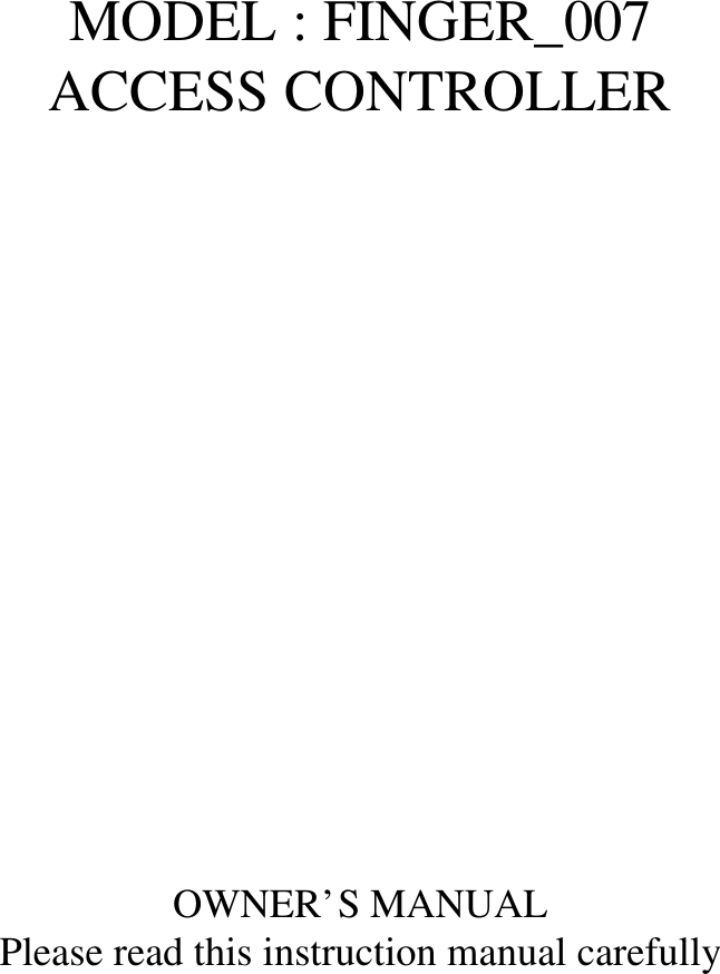
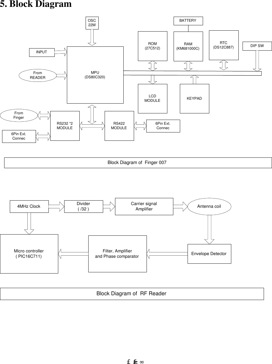
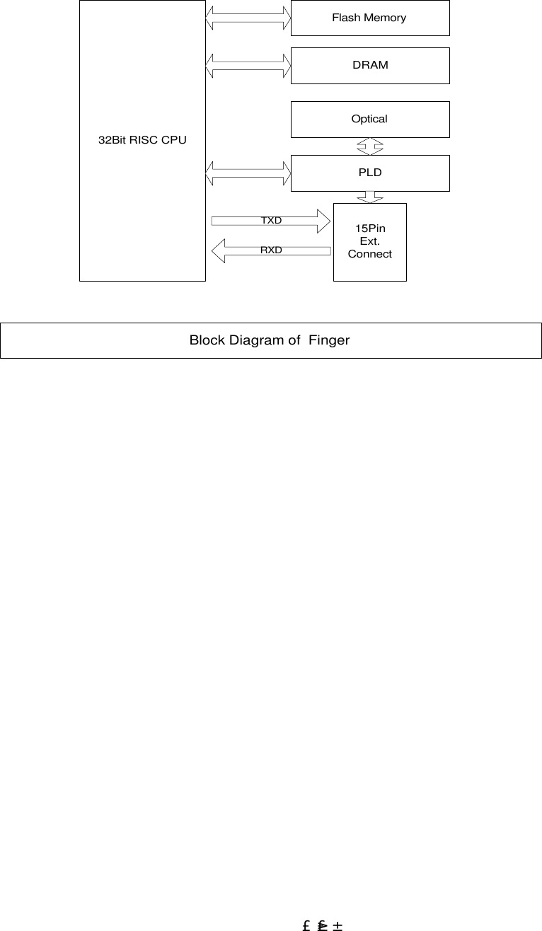
![£¶ 3.1. TABLE FOR WIRE COLORS POWER READER2 TTL OUTPUT COMMUNICATION INPUT NO FUNCTION COLOR 1 GND BLACK 2 +12V RED NO FUNCTION COLOR 1 D1 SKY BLUE 2 D0 PINK NO FUNCTION COLOR 1 TTL OUT1 ORANGE WITH WHITE LINE 2 TTL OUT2 BROWN WITH WHITE LINE NO FUNCTION COLOR 1 TX(-)[RS422] YELLOW 2 TX(+)[RS422] GRAY 3 RX(-)[RS422] BLUE 4 RX(+)[RS422] BROWN 5 TX[RS232] BLACK WITH WHITE LINE 6 RX[RS232] RED WITH WHITE LINE NO FUNCTION COLOR 1 IN1(EXIT) ORANGE 2 IN2(CONTACT) YELLOW WITH RED LINE 3 IN3(PIR) GREEN 4 IN(FIRE) GREEN WITH WHITE LINE](https://usermanual.wiki/ID-Teck-Co/FINGER007/User-Guide-128448-Page-6.png)
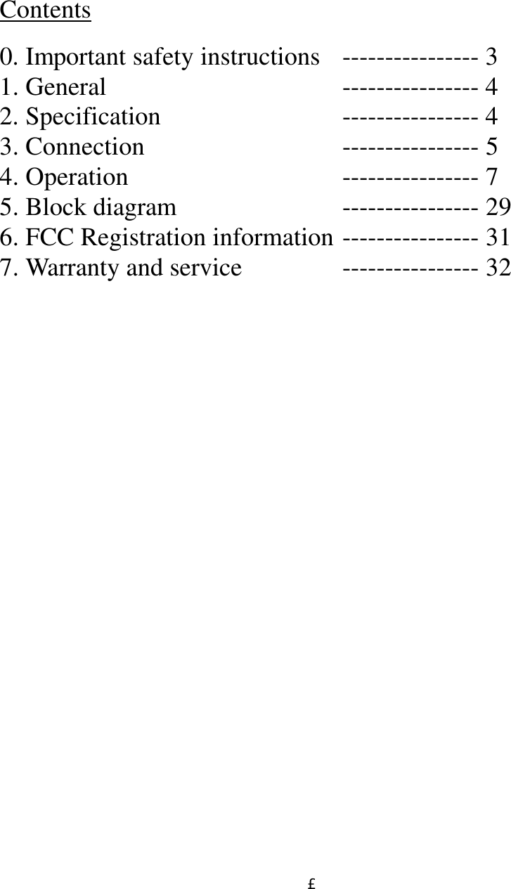
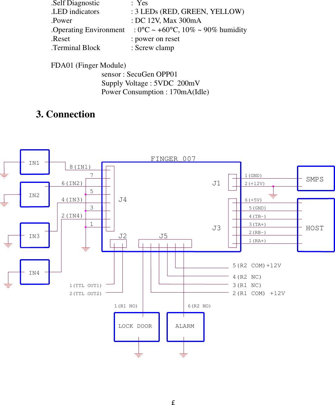
![£·RELAY 4. Operation A CAUTION: At first, to enter setup mode, press 00000000 and ENT on keypads. Then enter MASTER PASSWORD[3141]. When user power on FINGER_007, user see the following on LCD, where 02/18 11:59:11 means Month/Day Hour: Minute: second. Hence the following is not exactly same with the LCD, of which user see. Now, user can test normal operation (Normal mode) and change setting in FINGER_007 (Setup mode) Normal Mode 1. When user get registered card near FINGER_007, requesting PASSWORD or FingerPrint, user will see the green LED on, the RELAY1 active, and the following on LCD for three seconds. NO FUNCTION COLOR 1 R1 NC BLUE WITH WHITE LINE 2 R1 COM GRAY WITH RED LINE 3 R1 NO WHITE WITH RED LINE Door Relay 4 R2 NC PURPLE WITH WHITE LINE 5 R2 COM WHITE 6 R2 NO PURPLE Alarm Relay FINGER_007 [F1]02/18 11:59:12 <Fig 1> FINGER_007 Normal State FINGER_007 V0.1Granted Access<Fig 2> Normal Operation](https://usermanual.wiki/ID-Teck-Co/FINGER007/User-Guide-128448-Page-7.png)
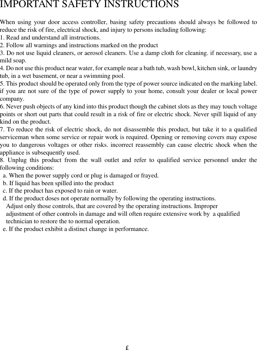
![£¸ 2. When user get unregistered card near FINGER_007, user will see the yellow LED on, the RELAY2 active, and the following on LCD about three seconds. Setup Mode Initially, When user press 8digit MASTER CARD number[00000000] and ENT, user see the following on LCD. Now press default Master password (3141). If Master Card and Master Password are matched, User will see, for a few second, the following message1, and then user is in setup mode. Note) When user changed MasterID, then master are required 1 It says the ID number of this FINGER_007 is 01. This ID number is necessary, when several FINGER_007s are connected to host. FINGER_007 V0.1UNREGISTERED ID<Fig 3> Abnormal Operation Master Password[____] <Fig 4> Wait state for Master password Communication ID 01 <Fig 5> Comm address](https://usermanual.wiki/ID-Teck-Co/FINGER007/User-Guide-128448-Page-8.png)
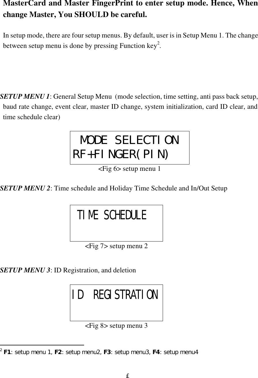
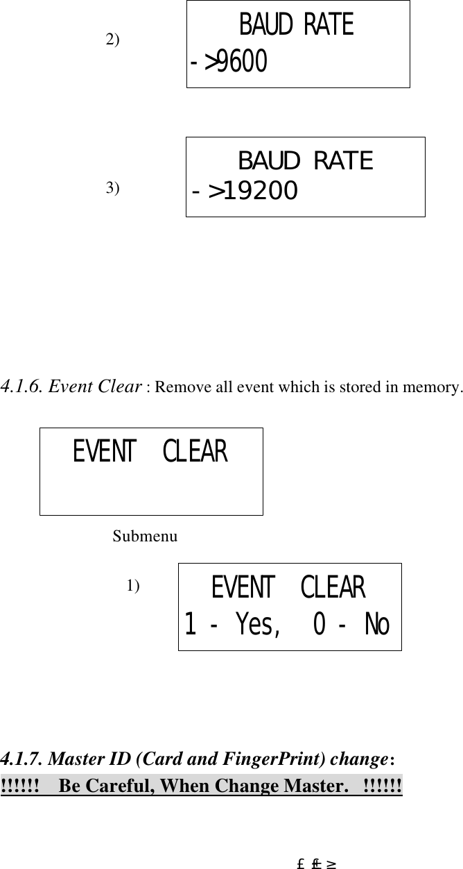
![£±£² 4.1.4. COMM ID SETTING : User can set Communication ID between 00-31. [ In abnormal case or when System Initialized, Comm ID is 00 ] Submenu : Press ‘ENT’, then User can change Comm Address[00-31] 4.1.5. Baud Rate : When FINGER_007 communicate with host, baud rate determine the speed. ( Default Baud rate of FINGER_007 is 9600 ) Submenu 1) APB SETUPNOT USECOMM ID SETTINGCOMM ADDRESS00BAUD RATE9600BAUD RATE->4800](https://usermanual.wiki/ID-Teck-Co/FINGER007/User-Guide-128448-Page-12.png)
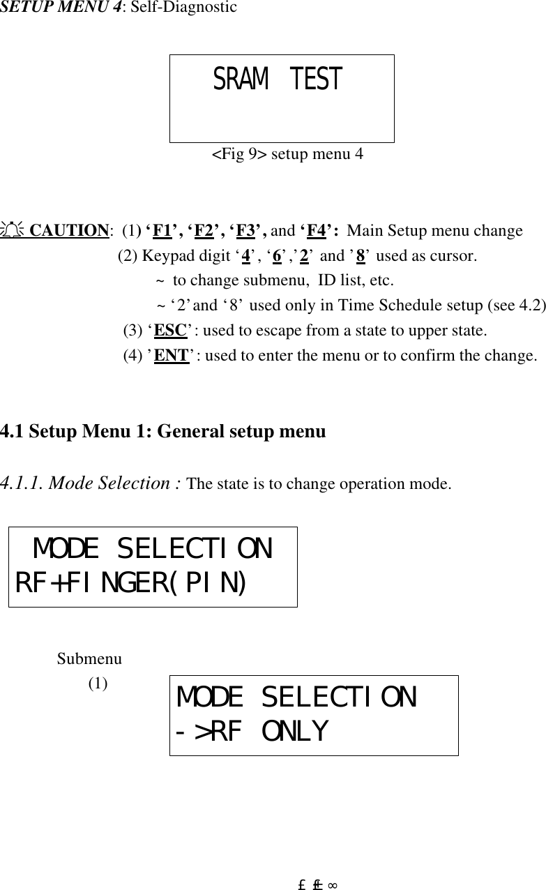
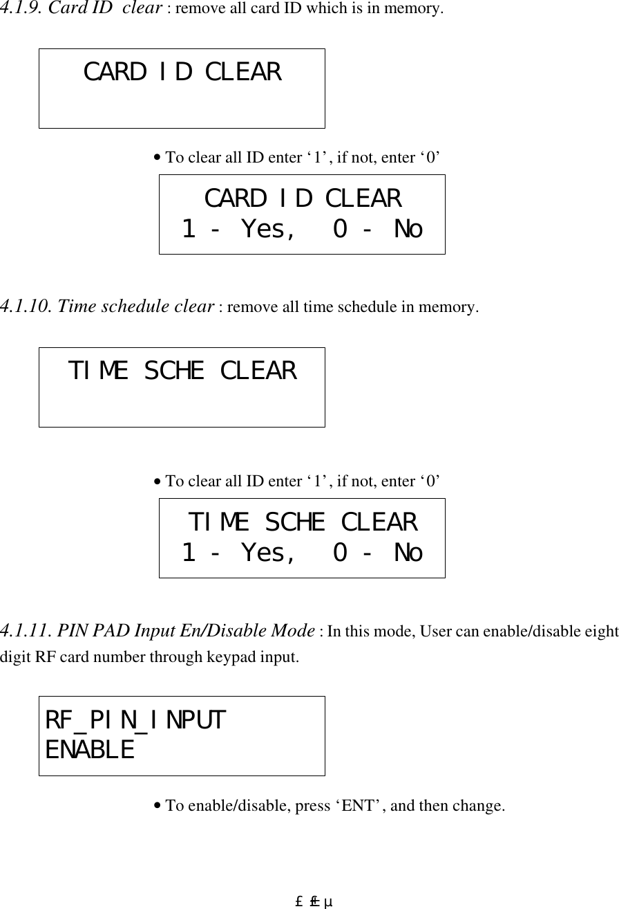
![£±£´ • Wait for a RF-CARD, which should be registered as a master card. • Wait for FingerPrint: If already Master is registered, then Master FingerPrint is required [old fingerprint] After Master FingerPrint is registered, ‘Master Card Registered’ message appear a few second. Now, Master Id and Password is changed. 4.1.8. System Initialize : Initialization of all setting value • To initialize enter ‘1’, if not, enter ‘0’ MASTER ID CHANGEScanning... SYS INITIALIZESYS INITIALIZE1 - Yes, 0 - No](https://usermanual.wiki/ID-Teck-Co/FINGER007/User-Guide-128448-Page-14.png)
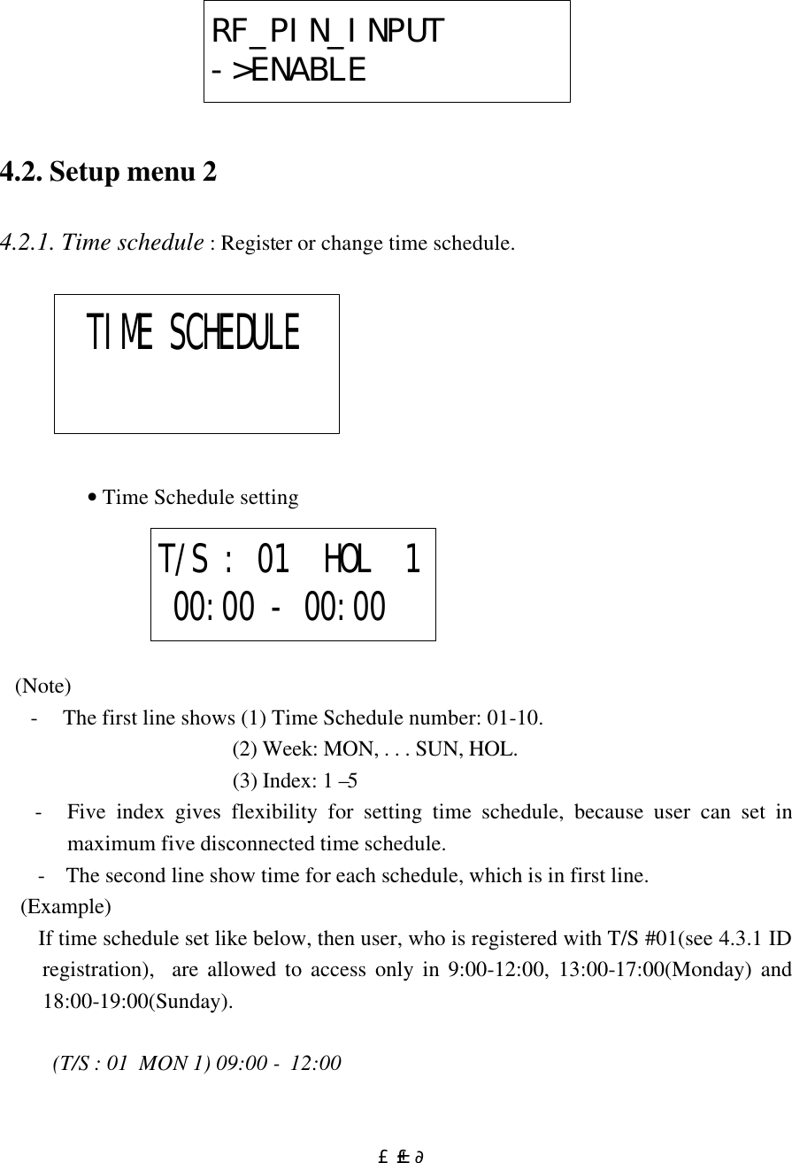
![£±£· (T/S : 01 MON 2) 13:00 - 17:00 (T/S : 01 SUN 1) 18:00 - 19:00 the other time schedule 00:00 - 00:00 4.2.2. Holiday Time schedule : Register or change time schedule. • Time Schedule setting (Note) - The first line shows (1) Holiday T/S number: 01-10. (2) Index for each Holiday T/S : 1–32. - The 32 index gives flexibility for setting Holiday time schedule, because user can set in maximum 32 Holiday time schedule for year. - The second line show [Month:Day] for each schedule, which is in first line. 4.2.3. In/Out define : set output for each input. Holiday T/SHOL T/S:01 #01 00:00IN/OUT DEFINE](https://usermanual.wiki/ID-Teck-Co/FINGER007/User-Guide-128448-Page-17.png)
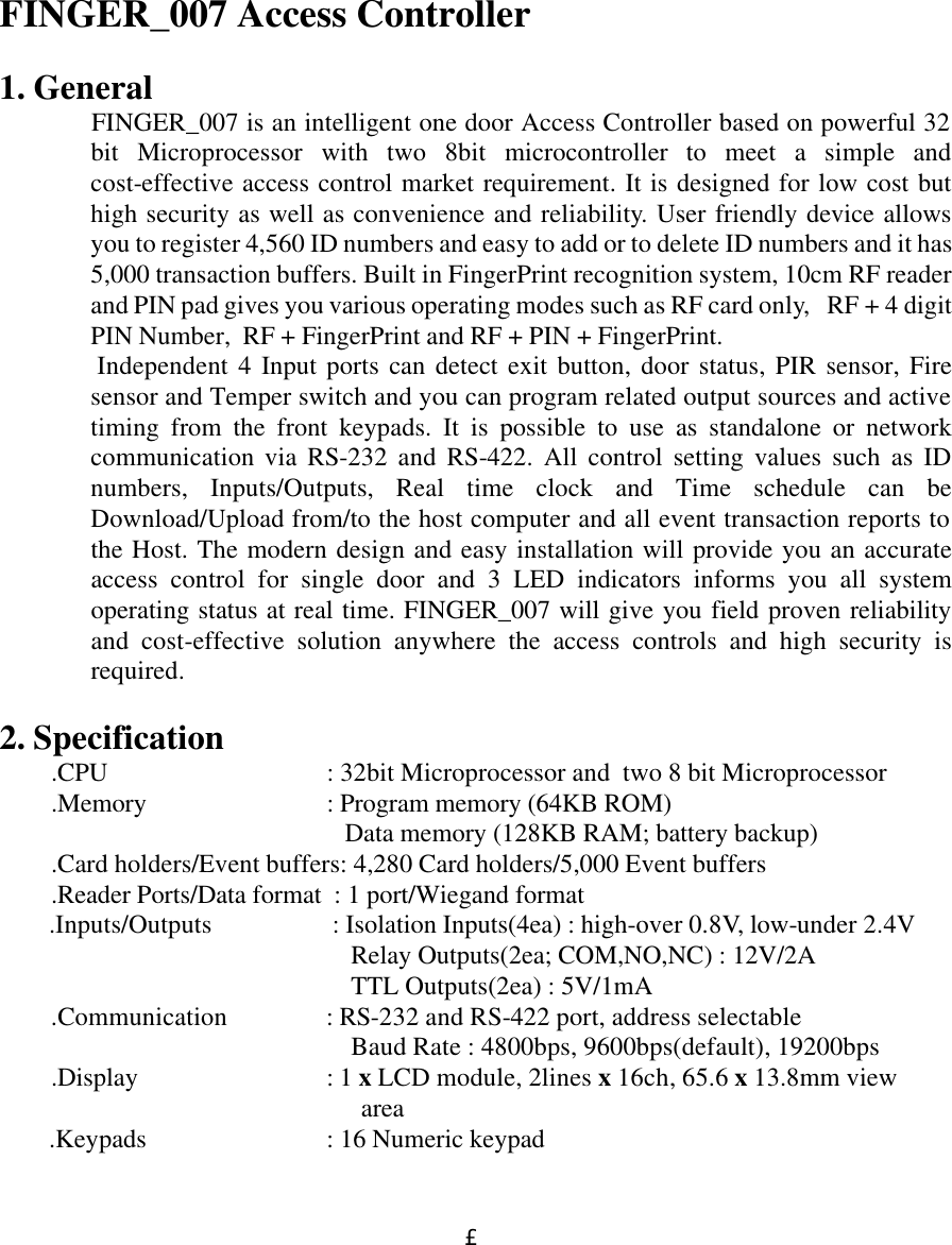
![£±£¸ • The relation between In and Out Note) 1) The relation between Index number and Input is in the table on the below. 2) Index number 9-13 is not used in FINGER_007. 3) The second line show for each index the output status. (see table) (00: no operation, 99: always on, 01-98: operation on the given seconds. ) 4) Input1(EXIT), Input2(CONTACT), Input3(PIR) and Input4(FIRE) 5) Relay1(LOCK DOOR) and Relay2(ALARM) (Table 1) The relation between Index, Input and Output(default) Index No Relay1 Relay2 TTL1 TTL2 Buzzer [1] Input1 03 00 00 00 00 [2] Input2 00 00 00 00 00 [3] Input3 00 00 03 00 00 [4] Input4 99 99 99 99 99 [5] Input5 00 99 99 99 99 [6] R/D1 OK 03 00 00 00 00 [7] R/D1 ID Error 00 03 00 00 00 [8] R/D1 T/S Error 00 03 00 00 00 [9] R/D1 APB Error 00 03 00 00 00 Index No.:0103 00 00 00 00](https://usermanual.wiki/ID-Teck-Co/FINGER007/User-Guide-128448-Page-18.png)
![£±£¹[10] R/D2 OK 03 00 00 00 00 [11] R/D2 ID Error 00 03 00 00 00 [12] R/D2 T/S Error 00 03 00 00 00 [13] R/D2 APB Error 00 03 00 00 00 [14] Output T/S 00 00 00 00 00 4.2.4. Holiday Index : Set Holiday Time Schedule number[01-10], which have to apply. • Set Holiday Index Number. HOLIDAY INDEXHOL INDEX: 00](https://usermanual.wiki/ID-Teck-Co/FINGER007/User-Guide-128448-Page-19.png)
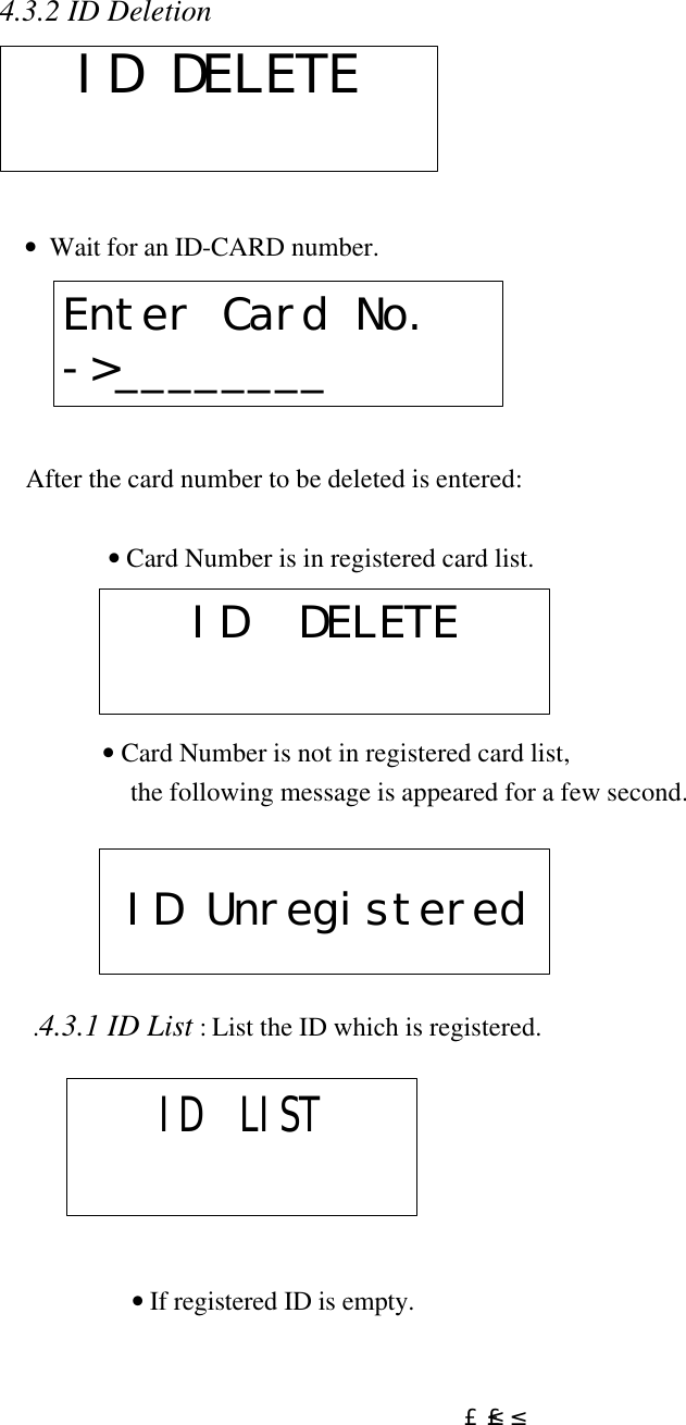
![£²£° 4.2.5. Mode Index : - Set Mode Time Schedule number[01-10], which have to apply. - If this Time Schedule is set (i.e. index number is not 00), then in RF+Finger mode or RF+PIN+Finger mode, user can use only RF only mode when mode time schedule is applied. • Set Mode Time Schedule Index Number. 4.3 Setup menu 3 4.3.1 ID Registration MODE INDEXMODE INDEX: 00ID REGISTRATION](https://usermanual.wiki/ID-Teck-Co/FINGER007/User-Guide-128448-Page-20.png)
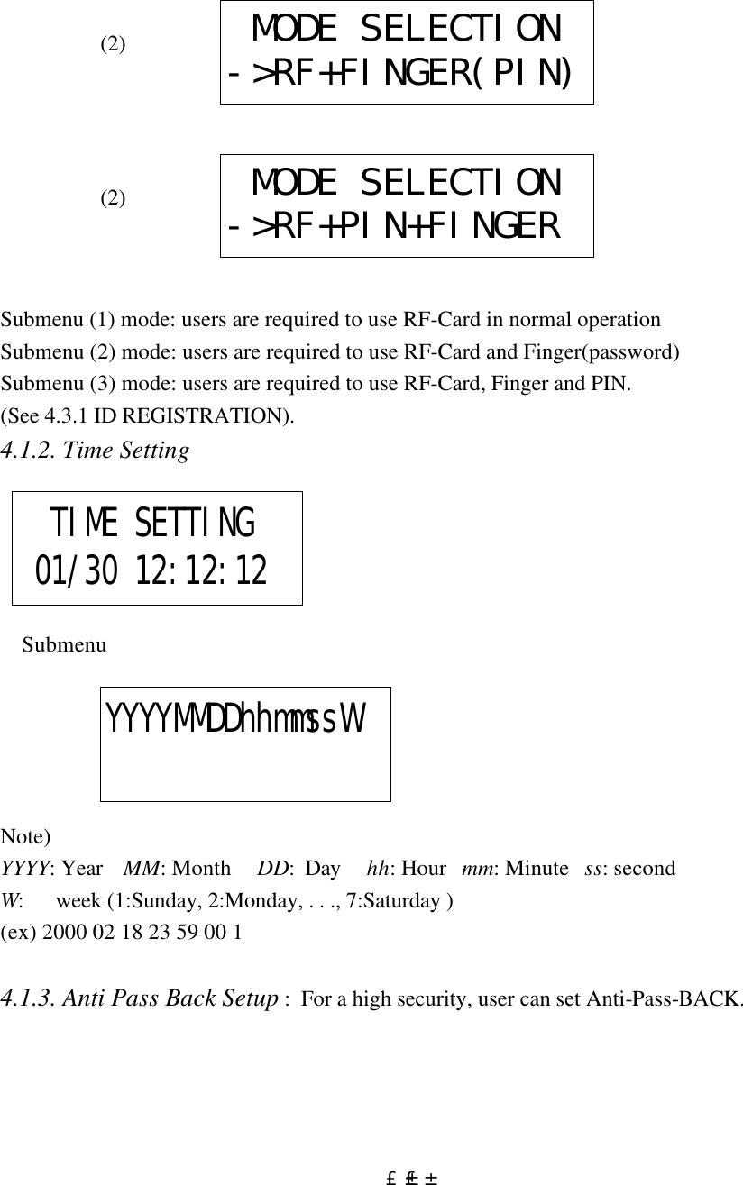
![£²£¹ • press ‘1’ allows you to initialize. press ‘0’ goes to RF_PIN_INPUT menu. Master Password[____] Master password is still ‘3141’ after the changed for master password. Message will be shown as below. System ClearCome OFF Reader2 2) RF_PIN_INPUT Enable / Disable once you make RF_PIN_INPUT disable, you should set for Master password before. If not, you cannot register any card number or menu. To set up RF_PIN_INPUT, you go to this menu as below. RF_PIN_INPUT1-USE, 0-NOT USE • ‘1’ Use. ‘0’ not use.](https://usermanual.wiki/ID-Teck-Co/FINGER007/User-Guide-128448-Page-29.png)