ID Teck Co FINGER007 Door Access Controller User Manual Finger007Manual
ID-Teck Co Ltd Door Access Controller Finger007Manual
manual
MODEL : FINGER_007
ACCESS CONTROLLER
OWNER’S MANUAL
Please read this instruction manual carefully

£²
Contents
0. Important safety instructions ---------------- 3
1. General ---------------- 4
2. Specification ---------------- 4
3. Connection ---------------- 5
4. Operation ---------------- 7
5. Block diagram ---------------- 29
6. FCC Registration information ---------------- 31
7. Warranty and service ---------------- 32
£³
IMPORTANT SAFETY INSTRUCTIONS
When using your door access controller, basing safety precautions should always be followed to
reduce the risk of fire, electrical shock, and injury to persons including following:
1. Read and understand all instructions.
2. Follow all warnings and instructions marked on the product
3. Do not use liquid cleaners, or aerosol cleaners. Use a damp cloth for cleaning. if necessary, use a
mild soap.
4. Do not use this product near water, for example near a bath tub, wash bowl, kitchen sink, or laundry
tub, in a wet basement, or near a swimming pool.
5. This product should be operated only from the type of power source indicated on the marking label.
if you are not sure of the type of power supply to your home, consult your dealer or local power
company.
6. Never push objects of any kind into this product though the cabinet slots as they may touch voltage
points or short out parts that could result in a risk of fire or electric shock. Never spill liquid of any
kind on the product.
7. To reduce the risk of electric shock, do not disassemble this product, but take it to a qualified
serviceman when some service or repair work is required. Opening or removing covers may expose
you to dangerous voltages or other risks. incorrect reassembly can cause electric shock when the
appliance is subsequently used.
8. Unplug this product from the wall outlet and refer to qualified service personnel under the
following conditions:
a. When the power supply cord or plug is damaged or frayed.
b. If liquid has been spilled into the product
c. If the product has exposed to rain or water.
d. If the product doses not operate normally by following the operating instructions.
Adjust only those controls, that are covered by the operating instructions. Improper
adjustment of other controls in damage and will often require extensive work by a qualified
technician to restore the to normal operation.
e. If the product exhibit a distinct change in performance.
£´
FINGER_007 Access Controller
1. General
FINGER_007 is an intelligent one door Access Controller based on powerful 32
bit Microprocessor with two 8bit microcontroller to meet a simple and
cost-effective access control market requirement. It is designed for low cost but
high security as well as convenience and reliability. User friendly device allows
you to register 4,560 ID numbers and easy to add or to delete ID numbers and it has
5,000 transaction buffers. Built in FingerPrint recognition system, 10cm RF reader
and PIN pad gives you various operating modes such as RF card only, RF + 4 digit
PIN Number, RF + FingerPrint and RF + PIN + FingerPrint.
Independent 4 Input ports can detect exit button, door status, PIR sensor, Fire
sensor and Temper switch and you can program related output sources and active
timing from the front keypads. It is possible to use as standalone or network
communication via RS-232 and RS-422. All control setting values such as ID
numbers, Inputs/Outputs, Real time clock and Time schedule can be
Download/Upload from/to the host computer and all event transaction reports to
the Host. The modern design and easy installation will provide you an accurate
access control for single door and 3 LED indicators informs you all system
operating status at real time. FINGER_007 will give you field proven reliability
and cost-effective solution anywhere the access controls and high security is
required.
2. Specification
.CPU : 32bit Microprocessor and two 8 bit Microprocessor
.Memory : Program memory (64KB ROM)
Data memory (128KB RAM; battery backup)
.Card holders/Event buffers: 4,280 Card holders/5,000 Event buffers
.Reader Ports/Data format : 1 port/Wiegand format
.Inputs/Outputs : Isolation Inputs(4ea) : high-over 0.8V, low-under 2.4V
Relay Outputs(2ea; COM,NO,NC) : 12V/2A
TTL Outputs(2ea) : 5V/1mA
.Communication : RS-232 and RS-422 port, address selectable
Baud Rate : 4800bps, 9600bps(default), 19200bps
.Display : 1 x LCD module, 2lines x 16ch, 65.6 x 13.8mm view
area
.Keypads : 16 Numeric keypad
£µ
.Self Diagnostic : Yes
.LED indicators : 3 LEDs (RED, GREEN, YELLOW)
.Power : DC 12V, Max 300mA
.Operating Environment : 0°C ~ +60°C, 10% ~ 90% humidity
.Reset : power on reset
.Terminal Block : Screw clamp
FDA01 (Finger Module)
sensor : SecuGen OPP01
Supply Voltage : 5VDC 200mV
Power Consumption : 170mA(Idle)
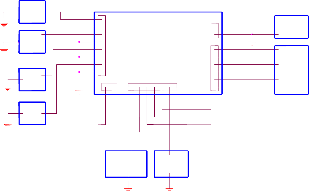
3. Connection
1(GND)
2(+12V)
SMPS
HOST
LOCK DOOR ALARM
2(R1 COM) +12V
J5
J4
J1
J3
IN1
IN4
IN2
IN3
1(R1 NO)
6(R2 NO)
3(R1 NC)
4(R2 NC)
5(R2 COM)+12V
8(IN1)
6(IN2)
4(IN3)
2(IN4)
7
5
3
1
FINGER_007
J2
6(+5V)
5(GND)
4(TB-)
2(RB-)
1(RA+)
3(TA+)
1(TTL OUT1)
2(TTL OUT2)

£
3.1. TABLE FOR WIRE COLORS
POWER
READER2
TTL OUTPUT
COMMUNICATION
INPUT
NO FUNCTION COLOR
1 GND BLACK
2 +12V RED
NO FUNCTION COLOR
1 D1 SKY BLUE
2 D0 PINK
NO FUNCTION COLOR
1 TTL OUT1 ORANGE WITH WHITE LINE
2 TTL OUT2 BROWN WITH WHITE LINE
NO FUNCTION COLOR
1 TX(-)[RS422] YELLOW
2 TX(+)[RS422] GRAY
3 RX(-)[RS422] BLUE
4 RX(+)[RS422] BROWN
5 TX[RS232] BLACK WITH WHITE LINE
6 RX[RS232] RED WITH WHITE LINE
NO FUNCTION COLOR
1 IN1(EXIT) ORANGE
2 IN2(CONTACT) YELLOW WITH RED LINE
3 IN3(PIR) GREEN
4 IN(FIRE) GREEN WITH WHITE LINE

£·
RELAY
4. Operation
A
CAUTION:
At first, to enter setup mode, press 00000000 and ENT on keypads. Then enter
MASTER PASSWORD[3141].
When user power on FINGER_007, user see the following on LCD, where 02/18 11:59:11
means Month/Day Hour: Minute: second. Hence the following is not exactly same with
the LCD, of which user see. Now, user can test normal operation (Normal mode) and
change setting in FINGER_007 (Setup mode)
Normal Mode
1. When user get registered card near FINGER_007, requesting PASSWORD or
FingerPrint, user will see the green LED on, the RELAY1 active, and the following on
LCD for three seconds.
NO FUNCTIO
N COLOR
1 R1 NC BLUE WITH WHITE LINE
2 R1 COM GRAY WITH RED LINE
3 R1 NO WHITE WITH RED LINE
Door
Relay
4 R2 NC PURPLE WITH WHITE LINE
5 R2 COM WHITE
6 R2 NO PURPLE
Alarm
Relay
FINGER_007 [F1]
02/18 11:59:12
<Fig 1> FINGER_007 Normal State
FINGER_007 V0.1
Granted Access
<Fig 2> Normal Operation

£¸
2. When user get unregistered card near FINGER_007, user will see the yellow LED on,
the RELAY2 active, and the following on LCD about three seconds.
Setup Mode
Initially, When user press 8digit MASTER CARD number[00000000] and ENT, user see
the following on LCD.
Now press default Master password (3141). If Master Card and Master Password are
matched, User will see, for a few second, the following message1, and then user is in setup
mode.
Note) When user changed MasterID, then master are required
1 It says the ID number of this FINGER_007 is 01. This ID number is necessary, when several
FINGER_007s are connected to host.
FINGER_007 V0.1
UNREGISTERED ID
<Fig 3> Abnormal Operation
Master Password
[____]
<Fig 4> Wait state for
Master password
Communication ID
01
<Fig 5> Comm address

£¹
MasterCard and Master FingerPrint to enter setup mode. Hence, When
change Master, You SHOULD be careful.
In setup mode, there are four setup menus. By default, user is in Setup Menu 1. The change
between setup menu is done by pressing Function key2.
SETUP MENU 1: General Setup Menu (mode selection, time setting, anti pass back setup,
baud rate change, event clear, master ID change, system initialization, card ID clear, and
time schedule clear)
SETUP MENU 2: Time schedule and Holiday Time Schedule and In/Out Setup
SETUP MENU 3: ID Registration, and deletion
2 F1: setup menu 1, F2: setup menu2, F3: setup menu3, F4: setup menu4
MODE SELECTION
RF+FINGER(PIN)
<Fig 6> setup menu 1
TIME SCHEDULE
<Fig 7> setup menu 2
ID REGISTRATION
<Fig 8> setup menu 3

£±£°
SETUP MENU 4: Self-Diagnostic
A
CAUTION: (1) ‘F1’, ‘F2’, ‘F3’, and ‘F4’: Main Setup menu change
(2) Keypad digit ‘4’, ‘6’,’2’ and ’8’ used as cursor.
~ to change submenu, ID list, etc.
~ ‘2’and ‘8’ used only in Time Schedule setup (see 4.2)
(3) ‘ESC’: used to escape from a state to upper state.
(4) ’ENT’: used to enter the menu or to confirm the change.
4.1 Setup Menu 1: General setup menu
4.1.1. Mode Selection : The state is to change operation mode.
Submenu
(1)
SRAM TEST
<Fig 9> setup menu 4
MODE SELECTION
RF+FINGER(PIN)
MODE SELECTION
->RF ONLY

£±£±
(2)
(2)
Submenu (1) mode: users are required to use RF-Card in normal operation
Submenu (2) mode: users are required to use RF-Card and Finger(password)
Submenu (3) mode: users are required to use RF-Card, Finger and PIN.
(See 4.3.1 ID REGISTRATION).
4.1.2. Time Setting
Submenu
Note)
YYYY: Year MM: Month DD: Day hh: Hour mm: Minute ss: second
W: week (1:Sunday, 2:Monday, . . ., 7:Saturday )
(ex) 2000 02 18 23 59 00 1
4.1.3. Anti Pass Back Setup : For a high security, user can set Anti-Pass-BACK.
MODE SELECTION
->RF+FINGER(PIN)
MODE SELECTION
->RF+PIN+FINGER
TIME SETTING
01/30 12:12:12
YYYYMMDDhhmmssW

£±£²
4.1.4. COMM ID SETTING : User can set Communication ID between 00-31. [ In
abnormal case or when System Initialized, Comm ID is 00 ]
Submenu : Press ‘ENT’, then User can change Comm Address[00-31]
4.1.5. Baud Rate : When FINGER_007 communicate with host, baud rate determine the
speed. ( Default Baud rate of FINGER_007 is 9600 )
Submenu
1)
APB SETUP
NOT USE
COMM ID SETTING
COMM ADDRESS
00
BAUD RATE
9600
BAUD RATE
->4800

£±£³
2)
3)
4.1.6. Event Clear : Remove all event which is stored in memory.
Submenu
1)
4.1.7. Master ID (Card and FingerPrint) change:
!!!!!! Be Careful, When Change Master. !!!!!!
BAUD RATE
->9600
BAUD RATE
->19200
EVENT CLEAR
EVENT CLEAR
1 - Yes, 0 - No

£±£´
• Wait for a RF-CARD, which should be registered as a master card.
• Wait for FingerPrint: If already Master is registered, then Master FingerPrint is
required [old fingerprint]
After Master FingerPrint is registered, ‘Master Card Registered’ message appear a few
second. Now, Master Id and Password is changed.
4.1.8. System Initialize : Initialization of all setting value
• To initialize enter ‘1’, if not, enter ‘0’
MASTER ID CHANGE
Scanning...
SYS INITIALIZE
SYS INITIALIZE
1 - Yes, 0 - No

£±£µ
4.1.9. Card ID clear : remove all card ID which is in memory.
• To clear all ID enter ‘1’, if not, enter ‘0’
4.1.10. Time schedule clear : remove all time schedule in memory.
• To clear all ID enter ‘1’, if not, enter ‘0’
4.1.11. PIN PAD Input En/Disable Mode : In this mode, User can enable/disable eight
digit RF card number through keypad input.
• To enable/disable, press ‘ENT’, and then change.
CARD ID CLEAR
CARD ID CLEAR
1 - Yes, 0 - No
TIME SCHE CLEAR
TIME SCHE CLEAR
1 - Yes, 0 - No
RF_PIN_INPUT
ENABLE

£±£
4.2. Setup menu 2
4.2.1. Time schedule : Register or change time schedule.
• Time Schedule setting
(Note)
- The first line shows (1) Time Schedule number: 01-10.
(2) Week: MON, . . . SUN, HOL.
(3) Index: 1 –5
- Five index gives flexibility for setting time schedule, because user can set in
maximum five disconnected time schedule.
- The second line show time for each schedule, which is in first line.
(Example)
If time schedule set like below, then user, who is registered with T/S #01(see 4.3.1 ID
registration), are allowed to access only in 9:00-12:00, 13:00-17:00(Monday) and
18:00-19:00(Sunday).
(T/S : 01 MON 1) 09:00 - 12:00
RF_PIN_INPUT
->ENABLE
TIME SCHEDULE
T/S : 01 HOL 1
00:00 - 00:00

£±£·
(T/S : 01 MON 2) 13:00 - 17:00
(T/S : 01 SUN 1) 18:00 - 19:00
the other time schedule 00:00 - 00:00
4.2.2. Holiday Time schedule : Register or change time schedule.
• Time Schedule setting
(Note)
- The first line shows (1) Holiday T/S number: 01-10.
(2) Index for each Holiday T/S : 1–32.
- The 32 index gives flexibility for setting Holiday time schedule, because user can
set in maximum 32 Holiday time schedule for year.
- The second line show [Month:Day] for each schedule, which is in first line.
4.2.3. In/Out define : set output for each input.
Holiday T/S
HOL T/S:01 #01
00:00
IN/OUT DEFINE

£±£¸
• The relation between In and Out
Note)
1) The relation between Index number and Input is in the table on the below.
2) Index number 9-13 is not used in FINGER_007.
3) The second line show for each index the output status. (see table)
(00: no operation, 99: always on, 01-98: operation on the given seconds. )
4) Input1(EXIT), Input2(CONTACT), Input3(PIR) and Input4(FIRE)
5) Relay1(LOCK DOOR) and Relay2(ALARM)
(Table 1) The relation between Index, Input and Output(default)
Index No Relay1 Relay2 TTL1 TTL2 Buzzer
[1] Input1 03 00 00 00 00
[2] Input2 00 00 00 00 00
[3] Input3 00 00 03 00 00
[4] Input4 99 99 99 99 99
[5] Input5 00 99 99 99 99
[6] R/D1 OK 03 00 00 00 00
[7] R/D1 ID Error 00 03 00 00 00
[8] R/D1 T/S Error 00 03 00 00 00
[9] R/D1 APB Error 00 03 00 00 00
Index No.:01
03 00 00 00 00

£±£¹
[10] R/D2 OK 03 00 00 00 00
[11] R/D2 ID Error 00 03 00 00 00
[12] R/D2 T/S Error 00 03 00 00 00
[13] R/D2 APB Error 00 03 00 00 00
[14] Output T/S 00 00 00 00 00
4.2.4. Holiday Index :
Set Holiday Time Schedule number[01-10], which have to apply.
• Set Holiday Index Number.
HOLIDAY INDEX
HOL INDEX: 00

£²£°
4.2.5. Mode Index :
- Set Mode Time Schedule number[01-10], which have to apply.
- If this Time Schedule is set (i.e. index number is not 00), then in RF+Finger mode
or RF+PIN+Finger mode, user can use only RF only mode when mode time
schedule is applied.
• Set Mode Time Schedule Index Number.
4.3 Setup menu 3
4.3.1 ID Registration
MODE INDEX
MODE INDEX: 00
ID REGISTRATION

£²£±
• Wait for an ID-CARD which will be registered.
• Wait for Personal Information
< Scanned Card ID number
< wait for personal information.
Note)
(1) The second line shows
Password + applied time schedule + Reader + Finger
(2) This Password is used in RF+PIN+FINGER mode.
-> Password is meaningless in RF only and RF+Finger mode.
(3) The possible time schedule number is eleven:
-> #00 means anytime access possible.
- > #01 - #10 which is set in 4.2.1 Time Schedule.
(4) Reader Access number:
‘1’: Reader_1 only access
‘2’: Reader_2 only access
‘3’: Reader_1 and Reader_2 access
(5) Finger Usage number:
`1’: User use finger
‘0’: User do not use finger
After Personal Information is entered, ‘ID Registered’ message appear a few second. Then
ID Registration is over for one ID Card. If user use Finger, then user must follow the
message on the LCD Now FINGER_007 is waiting for another ID card registration (i.e.
‘Scanning’ message is appear on LCD).
Scanning...
00342860
PW____TS__RD_FP_

£²£²
4.3.2 ID Deletion
• Wait for an ID-CARD number.
After the card number to be deleted is entered:
• Card Number is in registered card list.
• Card Number is not in registered card list,
the following message is appeared for a few second.
.4.3.1 ID List : List the ID which is registered.
• If registered ID is empty.
ID DELETE
Enter Card No.
->________
ID DELETE
ID Unregistered
ID LIST

£²£³
• If registered ID is not empty. ( press ‘3’ or ‘6’ to see the other registered ID)
Note) As we know, 00342860 is a ID number,
1111 is a password,
00 is a time schedule, and
3 is access Reader for ID 00342860.
1 is Finger Use.
4.4 Setup menu 4
4.4.1. SRAM test
MEMORY
EMPTY
00342860
1111 00 3 1

£²£´
• If RAM(KM681000C) is bad, then the message is the following
• If RAM(KM681000C) is good, the following message is appear on LCD
4.4.2. Output test : test five output port.
Outputs are On/Off three times.
(output1: relay1, output2: relay2, output3: TTL1, output4: TTL2, output5: Buzzer)
• When Output test finished, the following message appear on LCD
SRAM TEST
Memory fail!!! 0
RAM testing...
RAM test pass!!!
Press any key...
OUTPUT TEST

£²£µ
4.4.3. LCD test
• When LCD test is over the following message is appear
4.4.4. Keypad test
• When KeyPad test start, the following message is appear on LCD
Now, press keypad then the matched number will disappear.
(note: A-F is correspond to F1-F4, ESC and ENT )
OUTPUT 5
Press any key...
LCD TEST
Last Update
Press any key...
KEYPAD TEST
0123456789ABCDEF

£²£
4.4.5. Reader test
• Wait for test ID card
• Test Card Number which is read.
4.4.6. Input test : test five Input port and DIP switch.
• The following show input status
Note)
1) Input 1-4 : ‘0’ mean on (active) and ‘1’ mean off(inactive)
2) Input 5 (Temper switch): ‘0’ mean off and ‘1’ mean on.
READER TEST
Scanning...
Reader 1
00342860
INPUT TEST
INPUT TEST
1 1 1 1 1

£²£·
4.4.7. Communication test
To test communication with PC, connect Rx+ and Tx+ and connect Rx- and Tx-.
• The follwing show the communication is fail
• The following show the communication is success.
4.4.8. GET GAIN in FDA
To get gain in Finger_007, Press ‘ENT’.
• The follwing show the gain in FDA
COMM TEST
Tx data = 0
COMM fail
COMM test pass!!
Press any key...
GET GAIN in FDA
GAIN IN FDA-> 4

£²£¸
4.4.9. SET GAIN in FDA
To set gain in Finger_007, Press ‘ENT’.
• Enter ‘1’, ‘2’, ‘4’ or ‘8’ the gain in FDA
4.4.10. System Initialization for Error in machine.
If you are not sure to find which caused by error, put power off and connect reader 2 to
GND.
then put power on and it will show the message as below
!!!! !!!! if initialized, all data will be deleted. !!!!!!!!!!!
1) Initialization
System Initialize
1 - Yes, 0 - NO
SET GAIN in FDA
ENTER 1,2,4,or 8

£²£¹
• press ‘1’ allows you to initialize.
press ‘0’ goes to RF_PIN_INPUT menu.
Master Password
[____]
Master password is still ‘3141’ after the changed for master password.
Message will be shown as below.
System Clear
Come OFF Reader2
2) RF_PIN_INPUT Enable / Disable
once you make RF_PIN_INPUT disable, you should set for Master password before. If not,
you cannot register any card number or menu.
To set up RF_PIN_INPUT, you go to this menu as below.
RF_PIN_INPUT
1-USE, 0-NOT USE
• ‘1’ Use.
‘0’ not use.
£³£°
5. Block Diagram
OSC
22M
MPU
(DS80C320)
INPUT
RS422
MODULE
RS232 *2
MODULE
LCD
MODULE KEYPAD
ROM
(27C512) RAM
(KM681000C)
Block Diagram of Finger 007
From
Finger
BATTERY
RTC
(DS12C887) DIP SW
From
READER
6Pin Ext.
Connec
6Pin Ext.
Connec
4MHz Clock
Micro controller
( PIC16C711) Filter, Amplifier
and Phase comparator
Divider
( /32 )
Envelope Detector
Antenna coil
Block Diagram of RF Reader
Carrier signal
Amplifier
£³£±
32Bit RISC CPU
Flash Memory
DRAM
Optical
PLD
15Pin
Ext.
Connect
TXD
RXD
Block Diagram of Finger

£³£²
FCC REGISTRATION INFORMATION
FCC REQUIREMENTS PART 15
Caution: Any changes or modifications in construction of this device which are not
expressly approved by the responsible for compliance cold void the user's authority to
operate the equipment.
NOTE: This device complies with part 15 of the FCC Rules.
Operation is subject to the following two conditions:
1. This device may not cause harmful interference, and
2. This device must accept any interference received, including interference that may cause
undesired operation.
Note : This equipment has been tested and found to comply with the limits for a Class A digital device,
pursuant to part 15 of the FCC Rules. These limits are designed to provide reasonable protection
against harmful interference when the equipment is operated in a commercial environment. This
equipment generates, uses, and can radiate radio frequency energy and, if not installed and used in
accordance with the instruction manual, may cause harmful interference to radio communications.
Operation of this equipment in a residential area is likely to cause harmful interference in which case
the user will be required to correct the interference at his own expense.
WARRANTY AND SERVICE
The following warranty and service information applies only to the U.S. For information in other
countries, please contact your local distributor.
To obtain in or out of warranty service, please prepay shipment and return the unit to the appropriate
facility listed below.
IN THE UNITED STATES
RF LOGICS, INC. Service center
3026 SCOTT BLVD,
SANTA CLARA, CA 95054

£³£³
Tel. : (408) 980-0001
Fax.: (408) 980-8060
Email: webmaster@rflogics.com
Website : www.rflogics.com
OUTSIDE OF THE UNITED STATES
ID TECK CO., LTD. Service center
5F ACE TECHNOTOWER BLDG.
684-1 DUNGCHON-DONG, GANSUH-KU
SEOUL 157-030, KOREA
Tel. : 82-2-659-0055
Fax.: 82-2-659-0086
Email: webmaster@id-teck.com
Website : www.id-teck.com
Please use the original container, or pack the unit(s) in a sturdy carton with sufficient packing to
prevent damage. Include the following information:
1. A proof-of-purchase indicating model number and date of purchase.
2. Bill-to address
3. Ship-to address
4. Number and description of units shipped
5. Name and telephone number of person to call, should contact be necessary
6. Reason for return and description of the problem.
Damage occurring during shipment is deemed the responsibility of the carrier, and claims
should be made directly with the carrier.