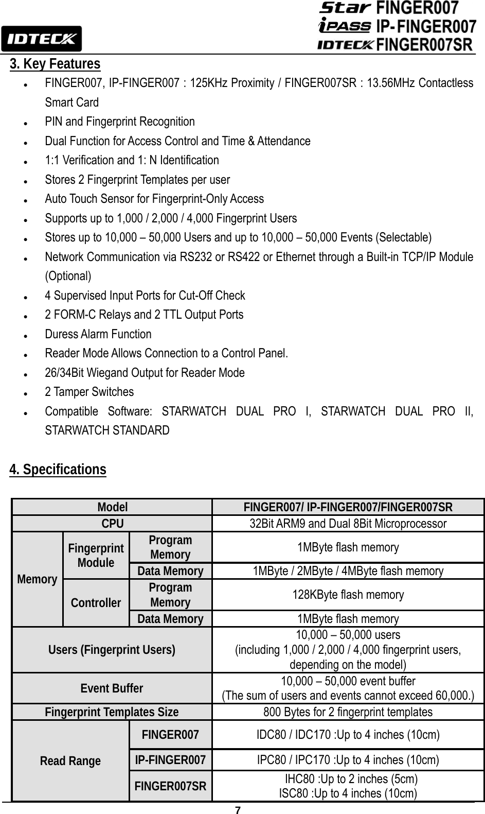
ID Teck Co FINGER007SR RFID & Biometrics Access Controller User Manual Appendix 4 Block Diagram
ID-Teck Co Ltd RFID & Biometrics Access Controller Appendix 4 Block Diagram
UserManual.wiki
>
ID Teck Co
>
FINGER007SR User Manual
User Manual
Navigation menu
Upload a User Manual
Namespaces
Wiki Guide
HTML
PDF
Info
Views
User Manual
Discussion / Help
Navigation
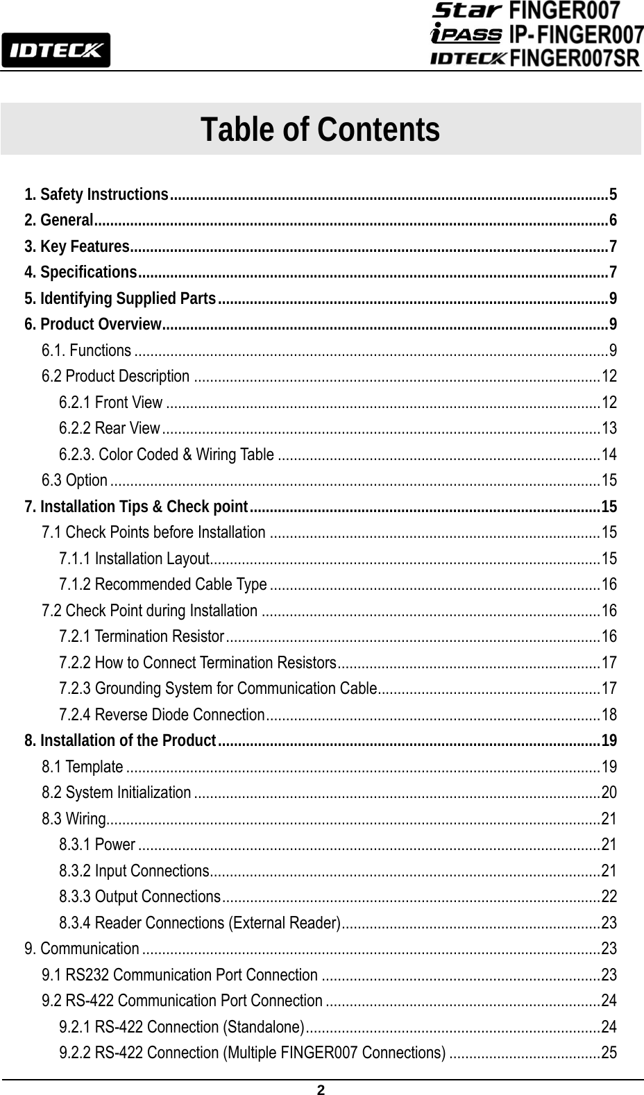
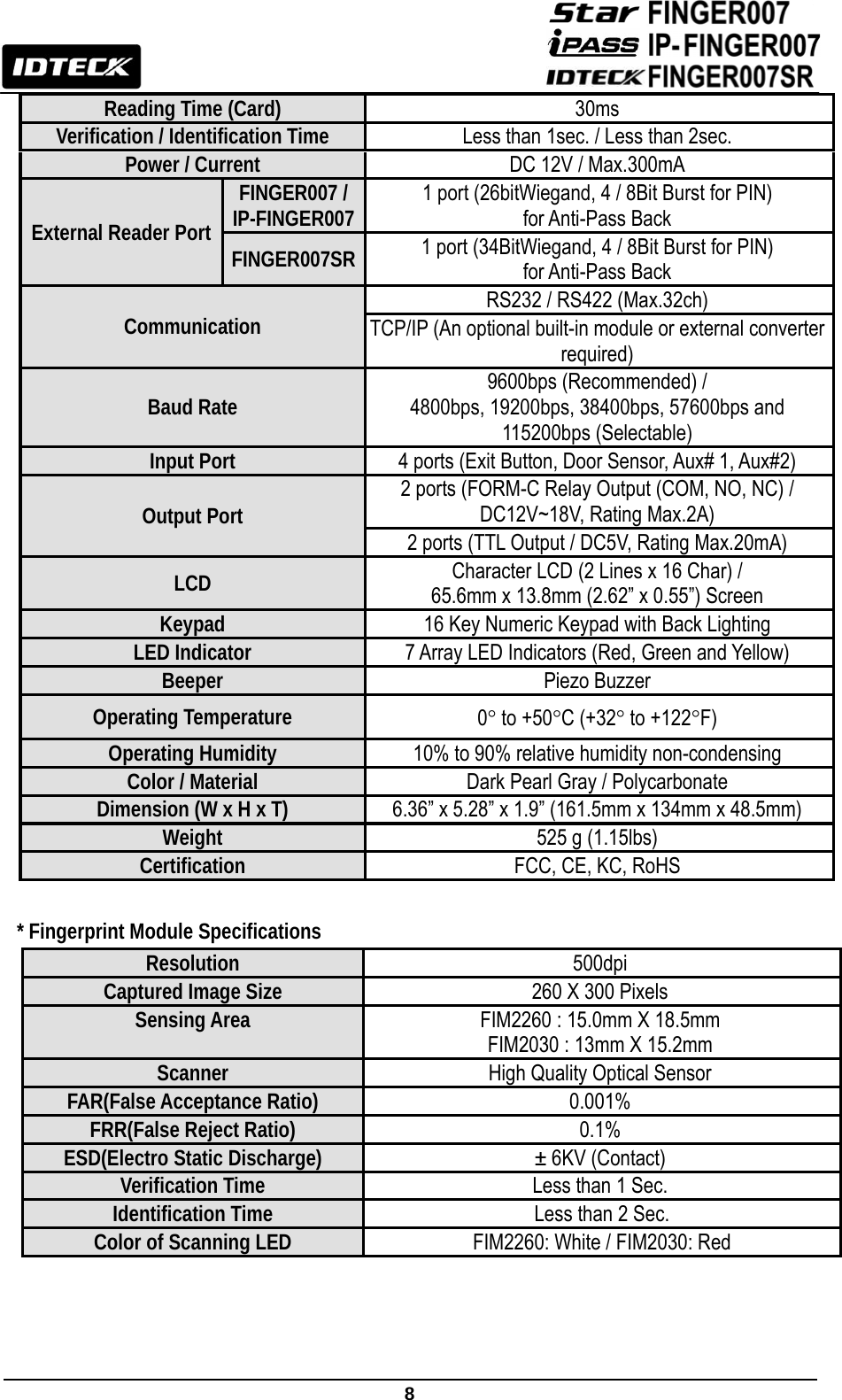

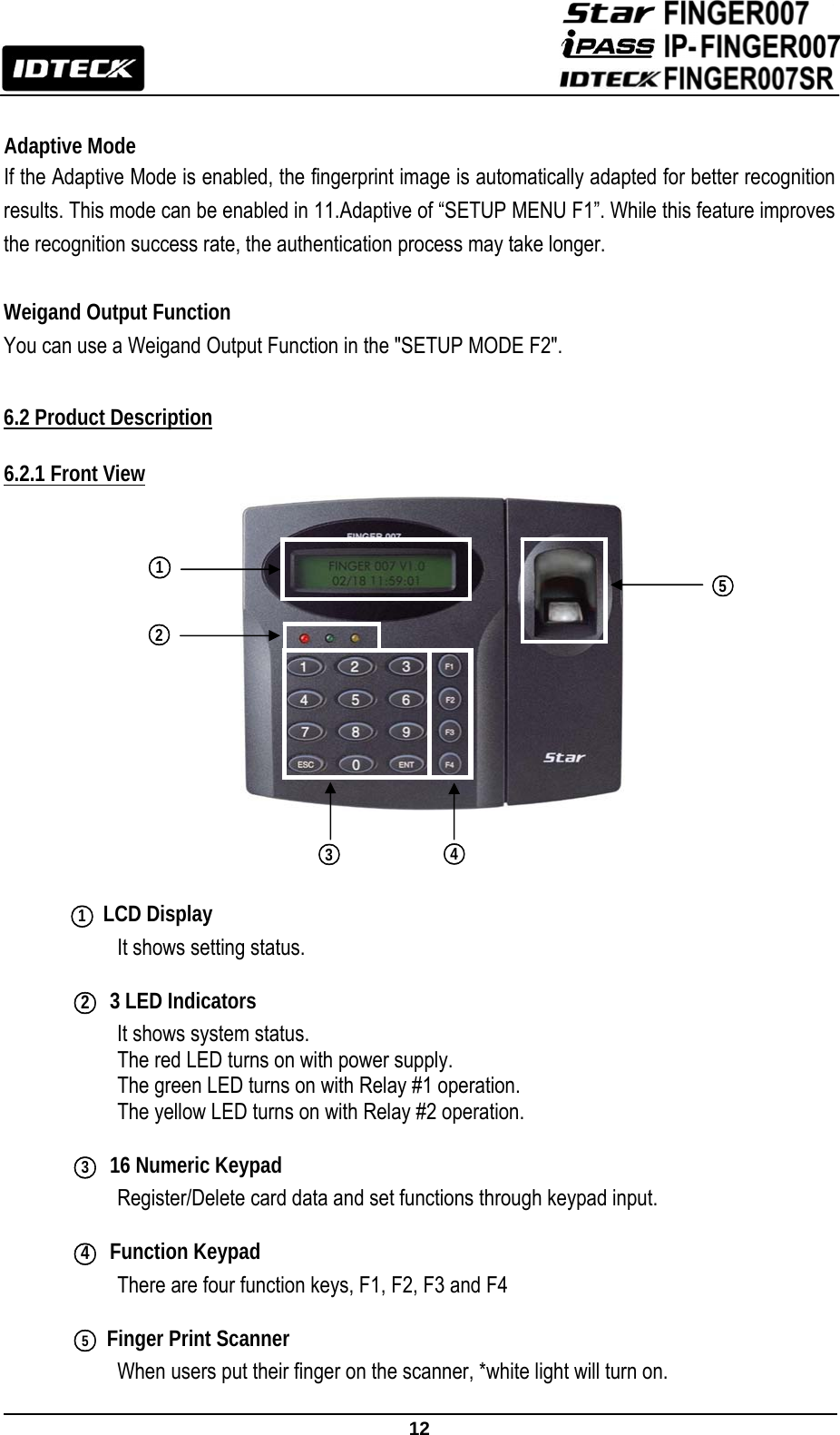
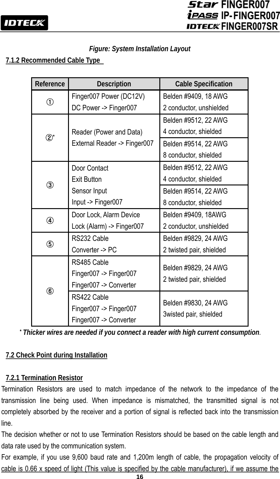
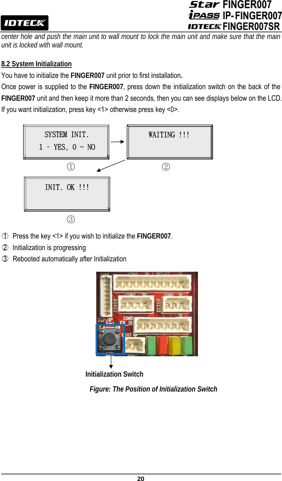


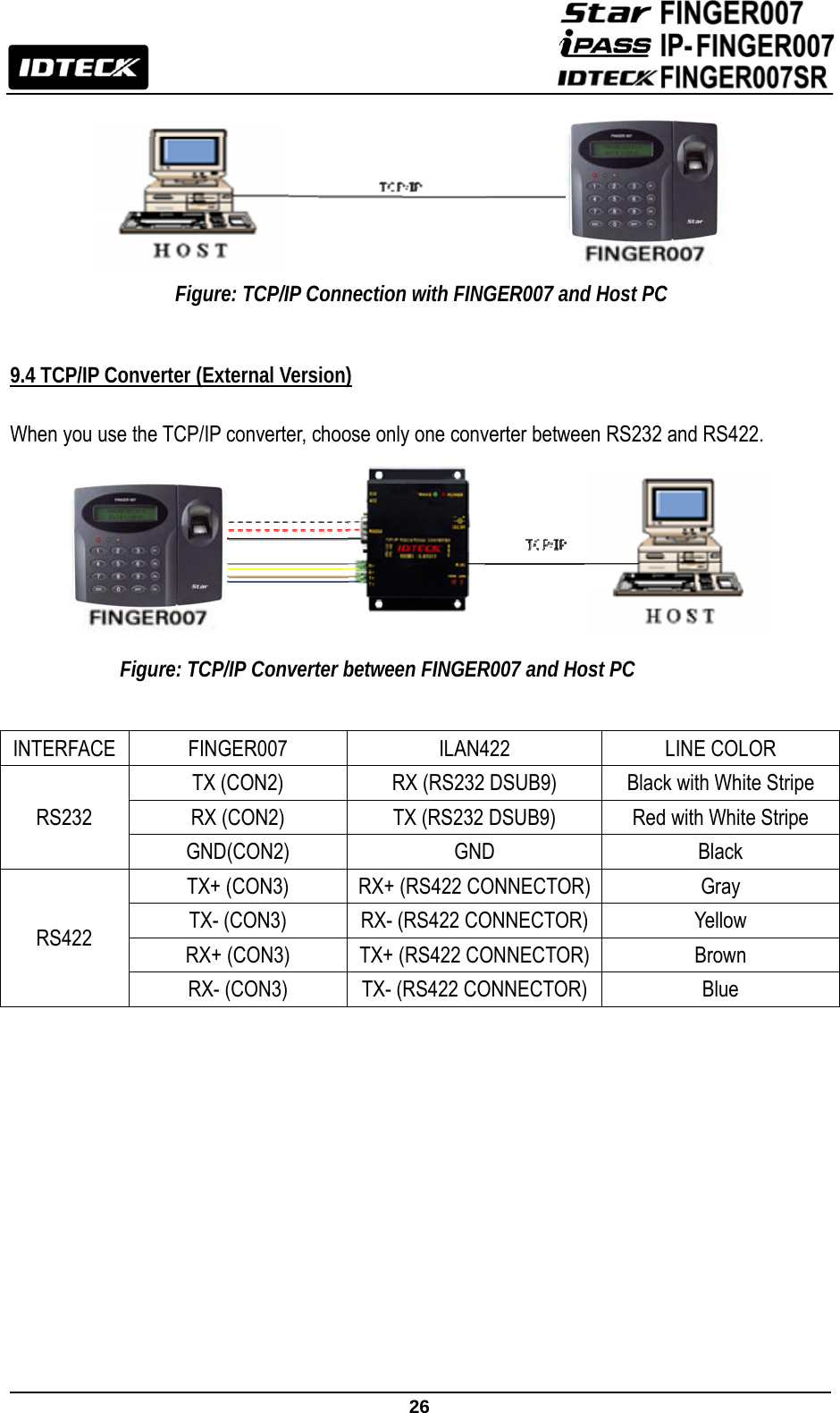
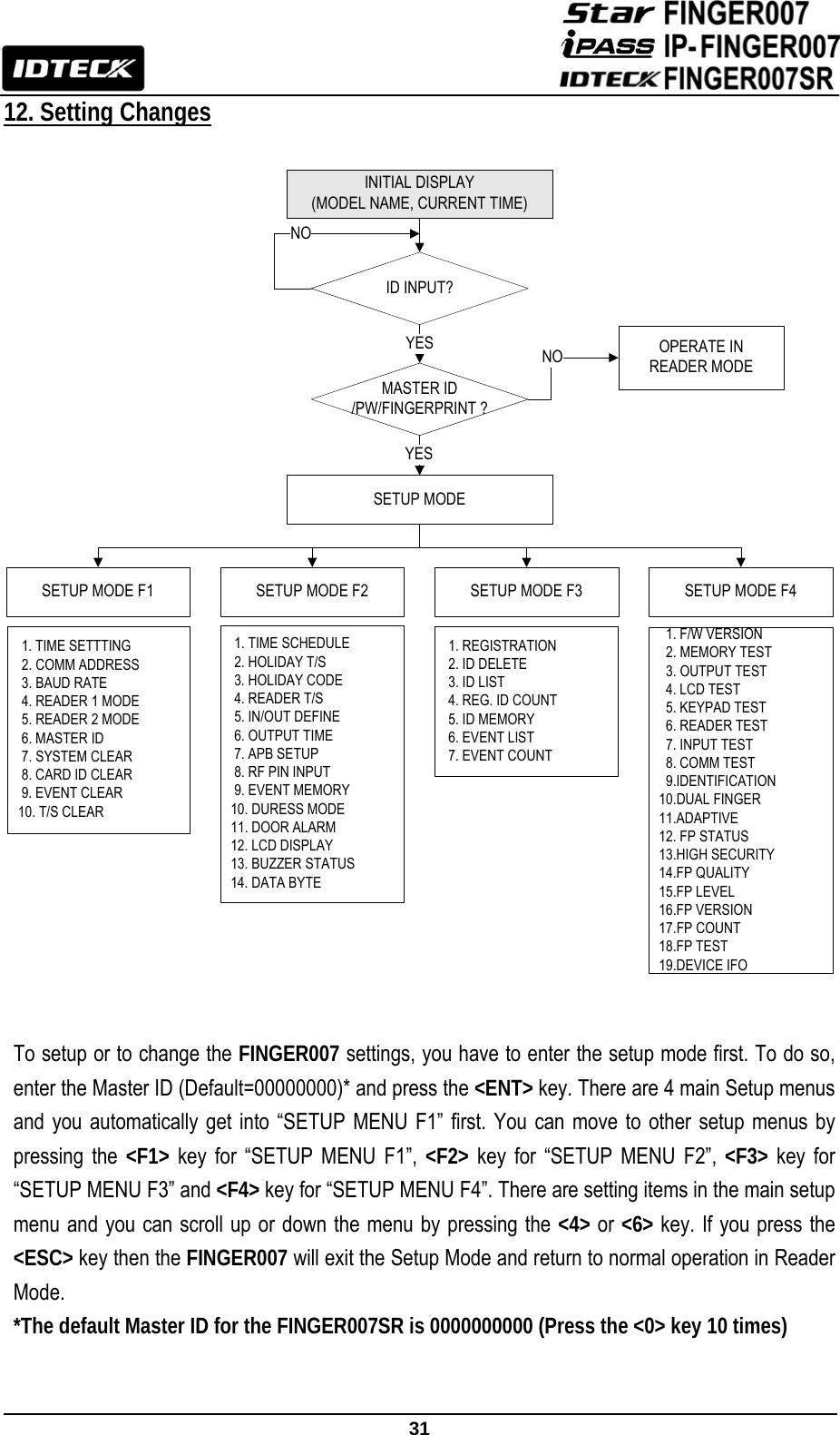
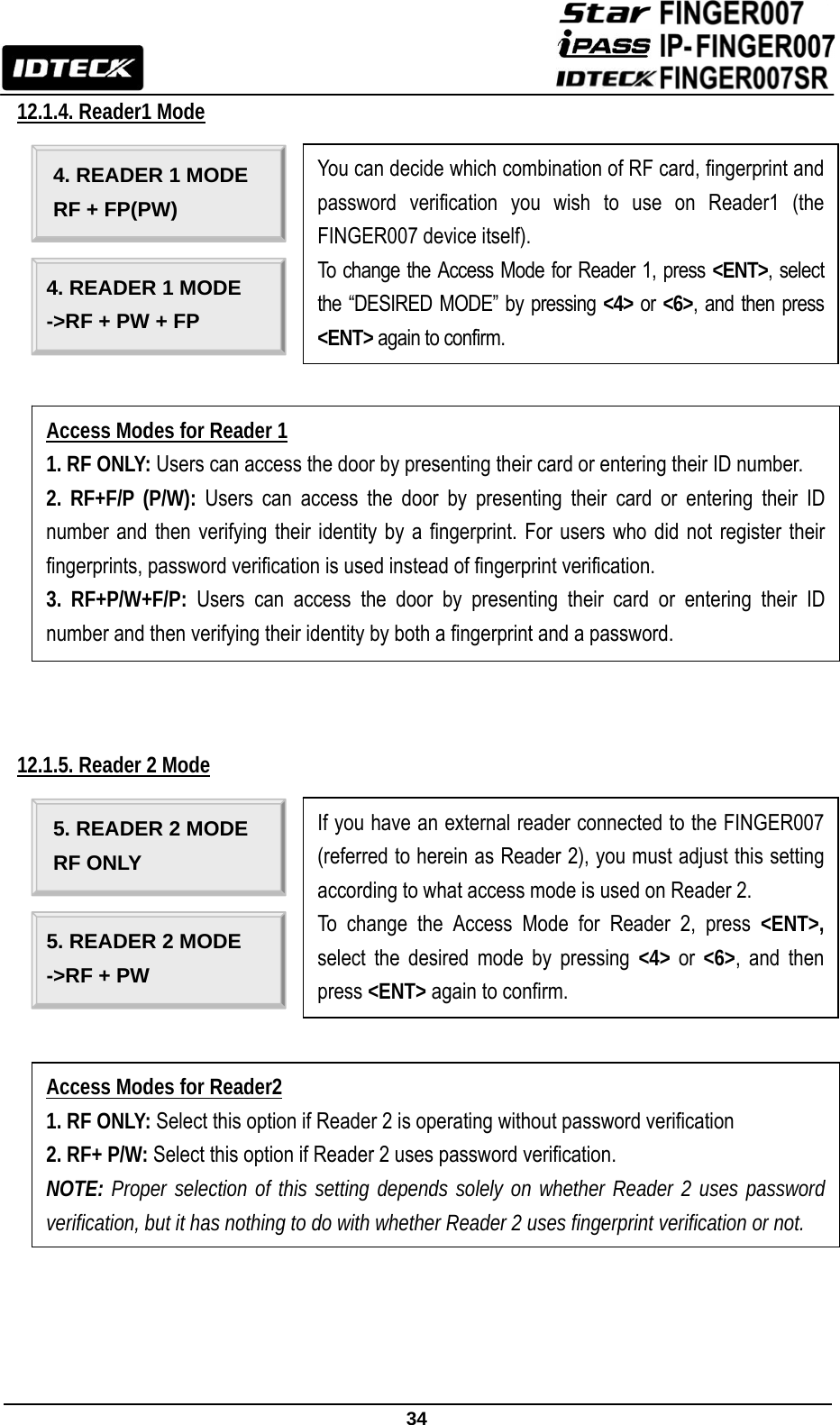
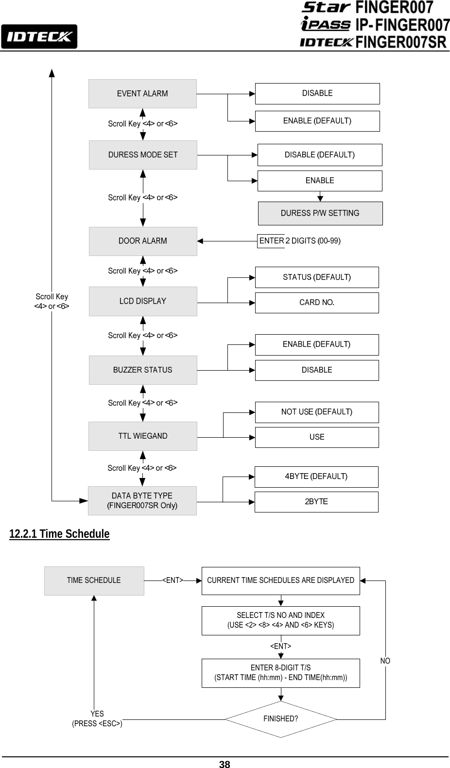
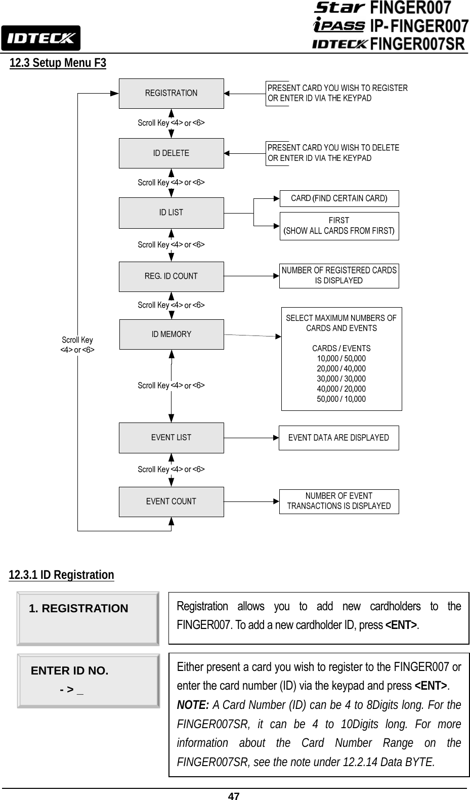
![27 10. Initial Setup 10.1 Initialization of FINGER007 After completing installation and cable connections, apply power (DC12V) to the FINGER007. Press down the initialization switch on the back of the FINGER007 unit and then keep it more than 2 seconds. Then, the LCD will first display “Initialize OK? 1: Yes 0: No”. Press <1> key if you want to initialize the system or <0> to cancel the initialization procedure. After all the initialization process is completed, the system will be operating in the normal mode and the LCD will display “FINGER007 [F1], MM/DD hh : mm : ss”. 10.2 Entering Setup Mode To setup or to change the FINGER007 settings, you have to enter the Setup Mode first. To do so, enter the Master ID (default=00000000)* and press the <ENT> key. There are 4 main Setup menus and you automatically get into “SETUP MENU F1” first. You can move to other Setup menus by pressing the <F1> key for “SETUP MENU F1”, <F2> key for “SETUP MENU F2”, <F3> key for “SETUP MENU F3” and <F4> key for “SETUP MENU F4”. There are setting items in the main Setup Menu and you can scroll up or down the menu by pressing the <4> or <6> key. If you press the <ESC> key then the FINGER007 will exit the Setup Mode and return to normal operation in Reader Mode. *The default Master ID for the FINGER007SR is 0000000000 (Press the <0> key 10 times) <1> KEY?“SYSTEM IN IT IA L IZ E D !!!”Power ONIn itia lize O K ?1: Yes 0: NoNormal OperationYesNoPress and hold the initialization button. Apply +12V DC power to the FINGER007.Release the button when the LCD displays “In itia lize O K ?”](https://usermanual.wiki/ID-Teck-Co/FINGER007SR/User-Guide-1574254-Page-28.png)

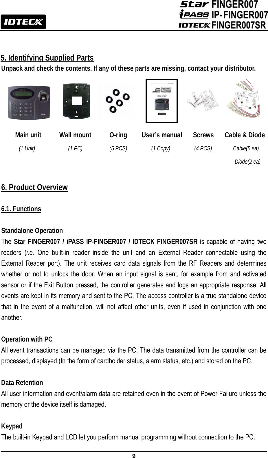
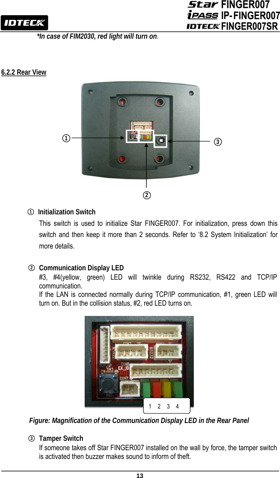
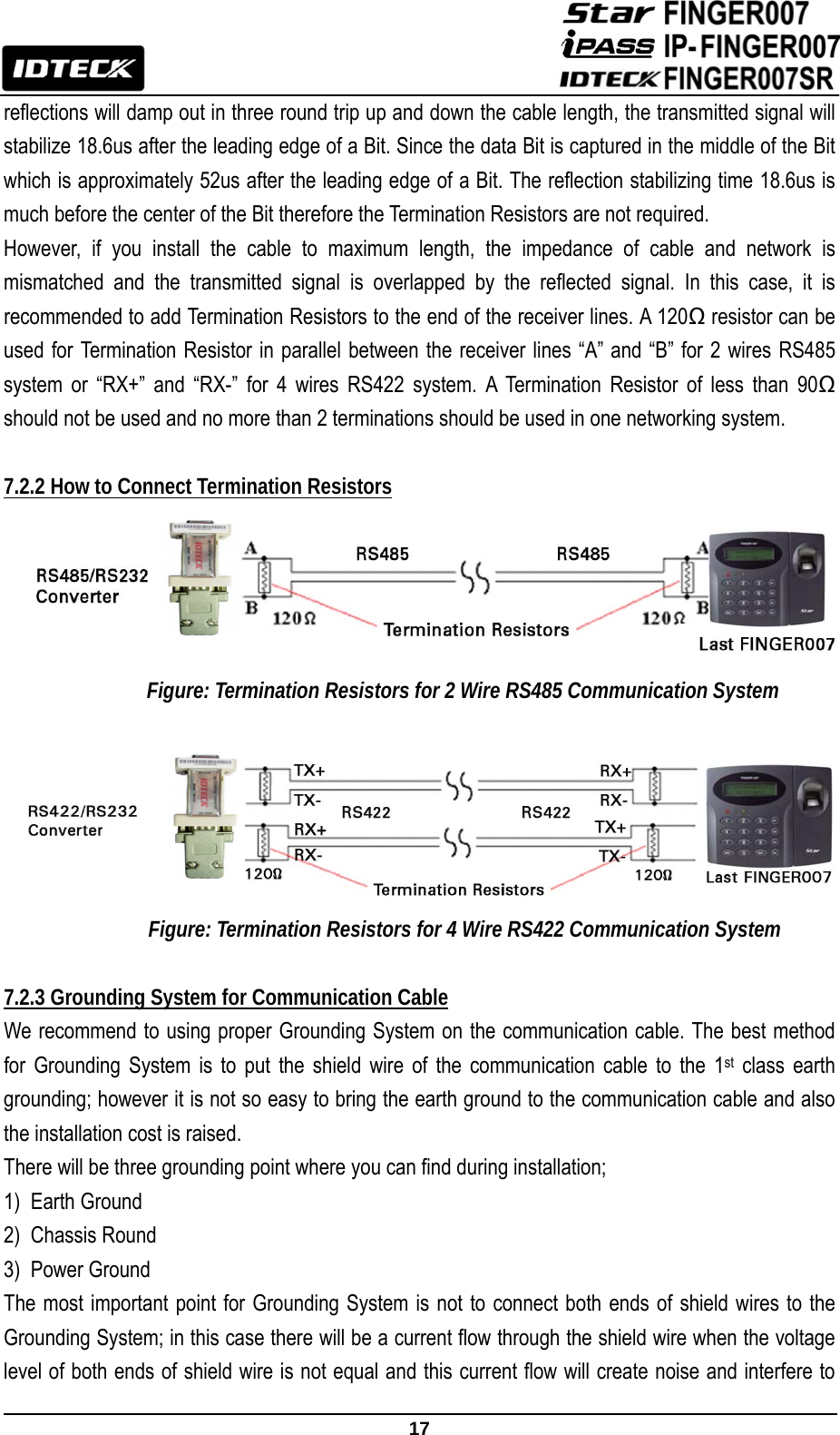
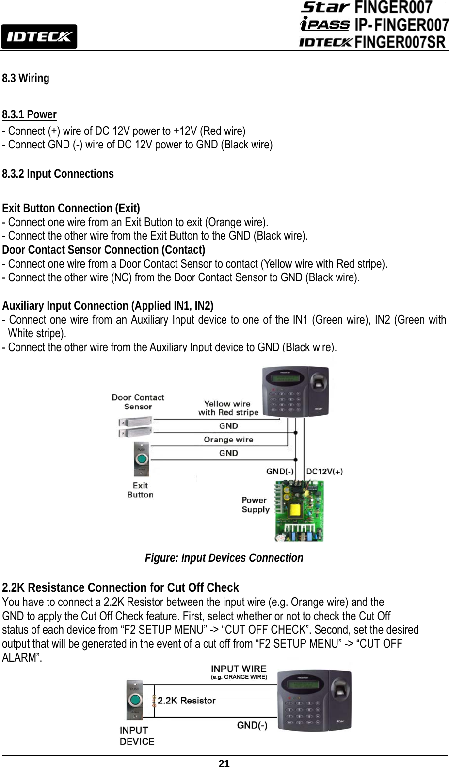
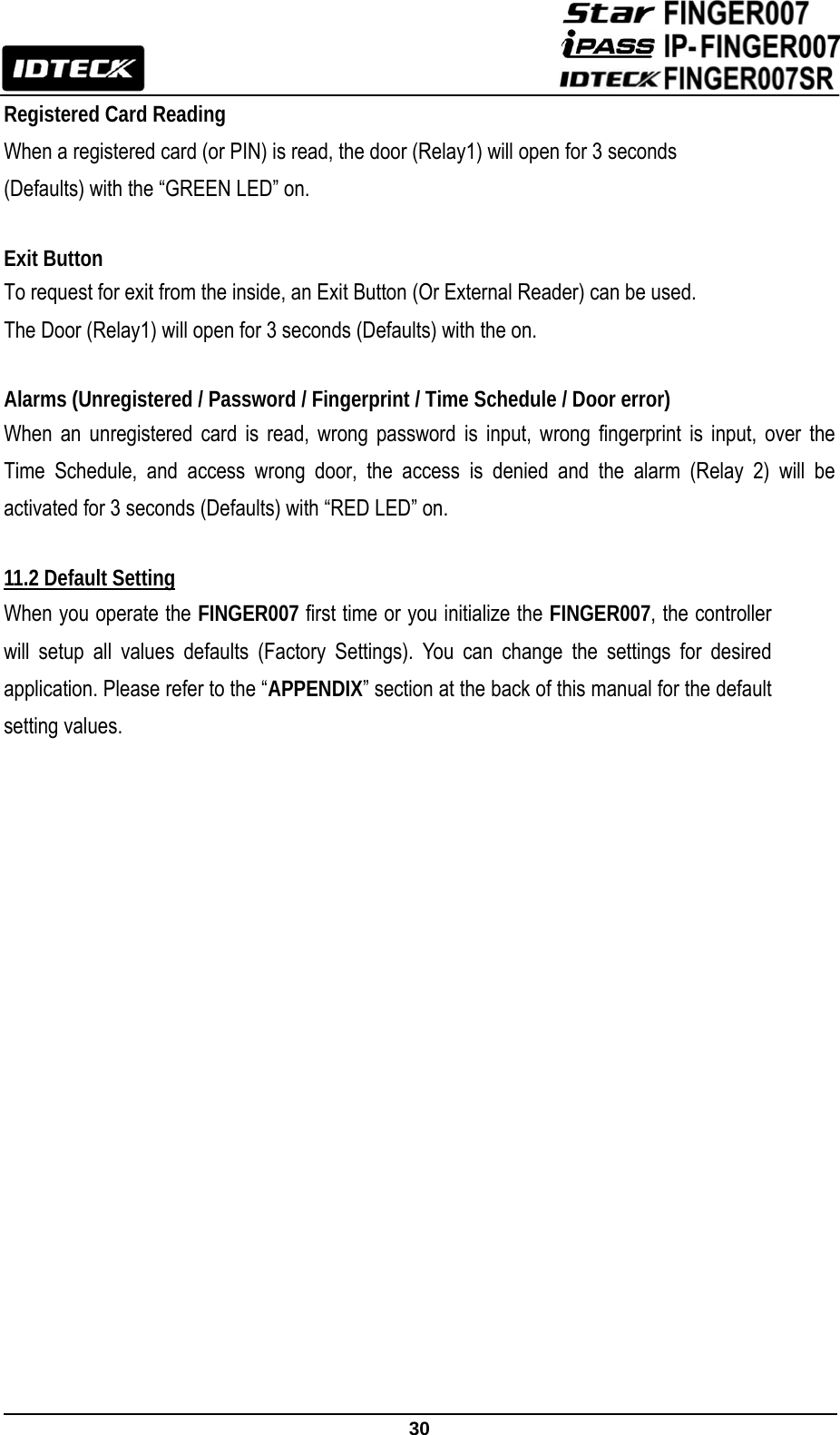
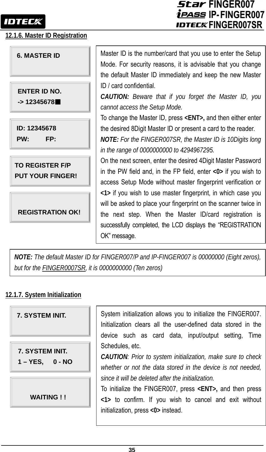
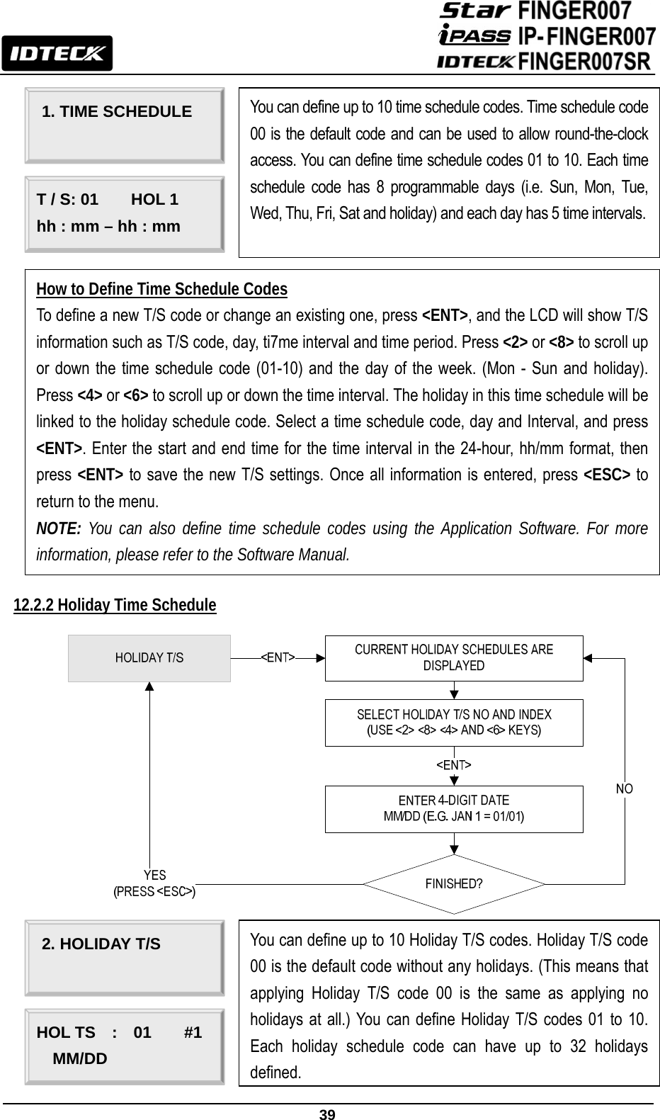
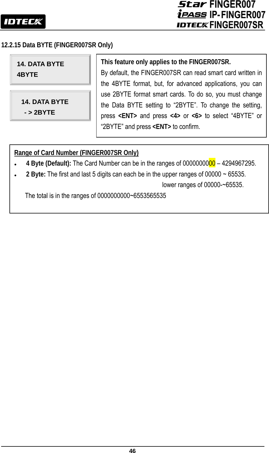
![29 10.5 Registering Cardholder IDs To add new cardholder IDs to the FINGER007, enter the Setup Mode (See 10.2 Entering Setup Mode), press <F3>. Once the 1.ID registration item appears on the LCD, press <ENT> to begin the ID registration process. For detailed information on the ID registration process, please refer to 12.3.1 ID registration. NOTE: How to place your finger onto the scanner when you register card ID: When you register or verify your fingerprint, please place your finger onto the scanner correctly as illustrated below. Figure: How to Put Your Finger on the Scanner 11. Operation 11.1 Normal Operation Power On When the power is applied to FINGER007, the “RED LED” is turned on. Fingerprint Identification 1. If registered card is read by the unit, red LED of fingerprint sensor is on. At this time, you should put your finger and then remove your finger if red LED is off. 2. If fingerprint identification is done, card ID or authorization status appears on the LCD and fingerprint quality level also appears. e.g.) [Q3] 3. Quality level appears from 1 to 5. In case of Q1 or Q2, you can’t use on Identification Mode (1: N) because of bad quality. In case of Q3, Q4 or Q5, you can use on Identification Mode (1: N) because of good quality. e.g.) In case of fingerprint identification – Quality Level: 3, Card ID: 12300111](https://usermanual.wiki/ID-Teck-Co/FINGER007SR/User-Guide-1574254-Page-30.png)

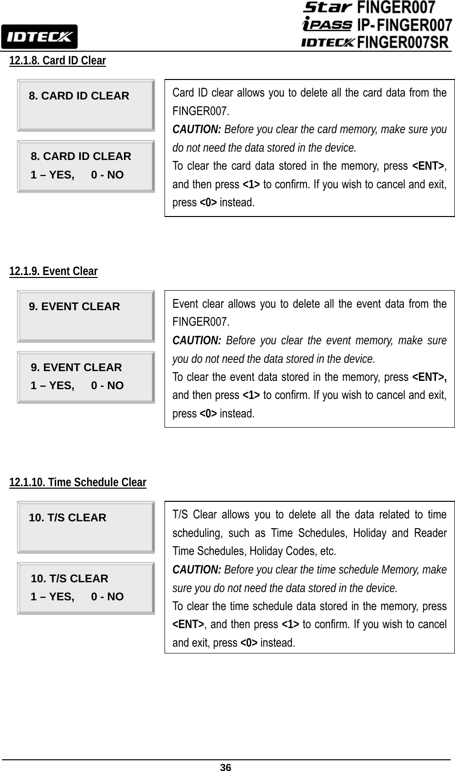
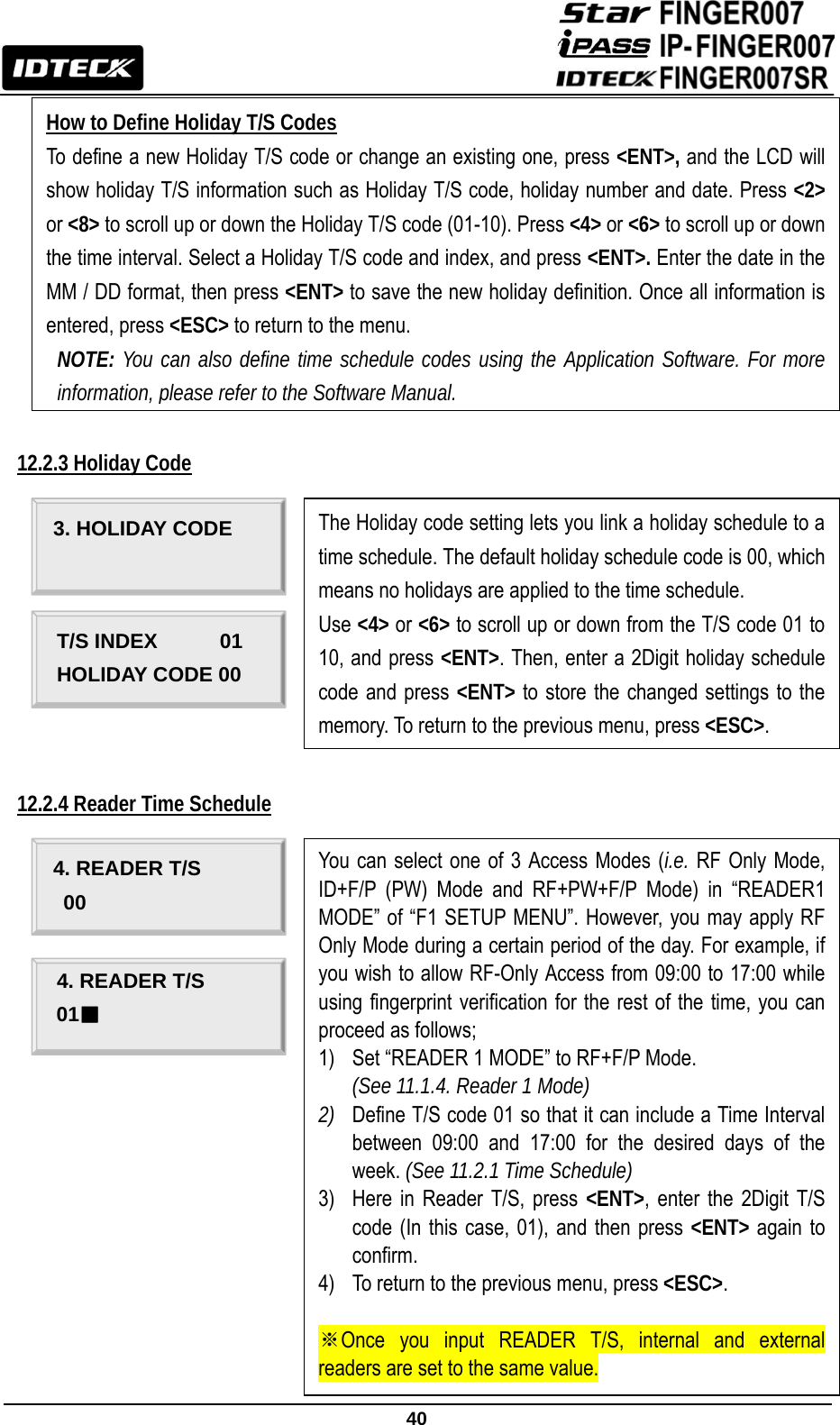
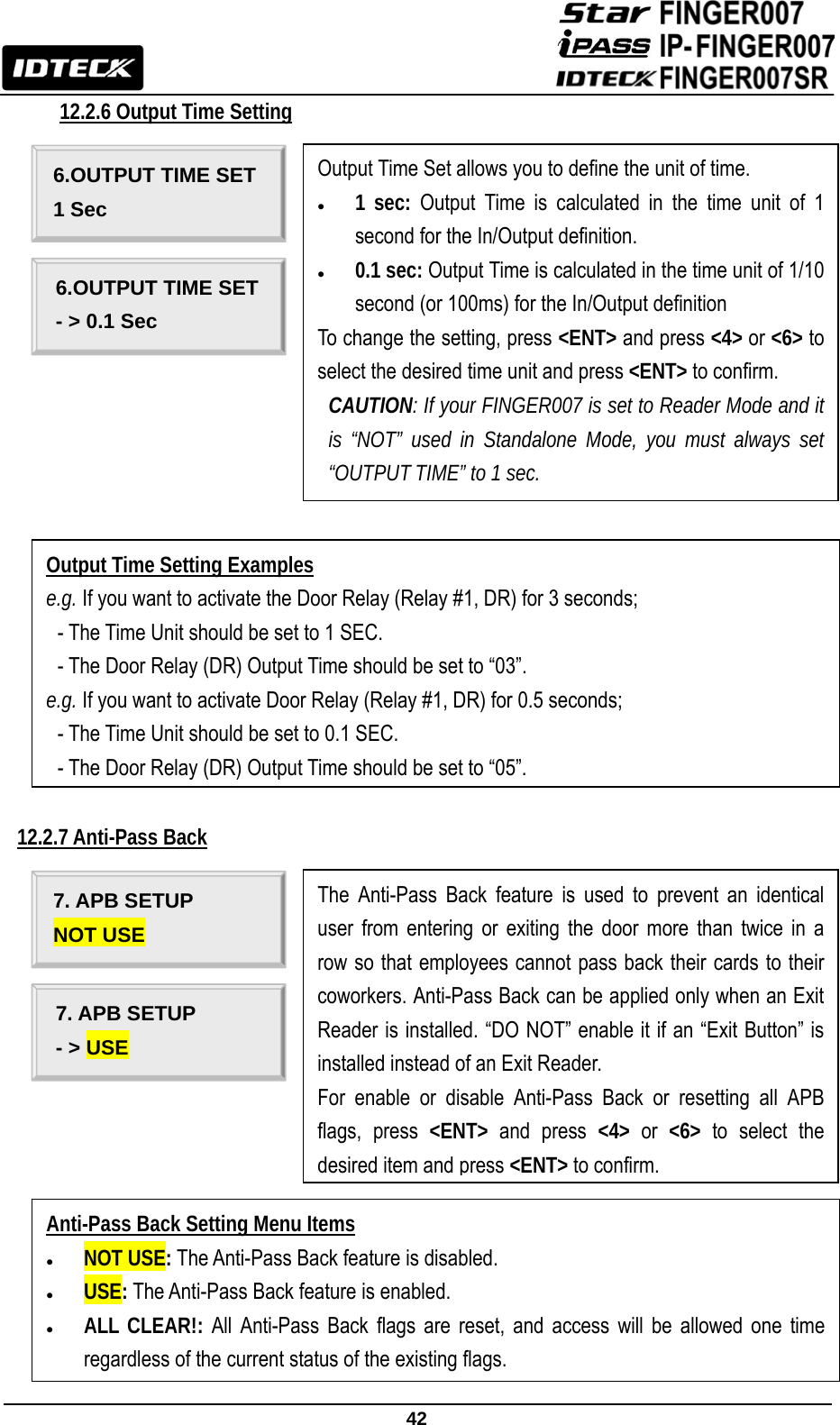


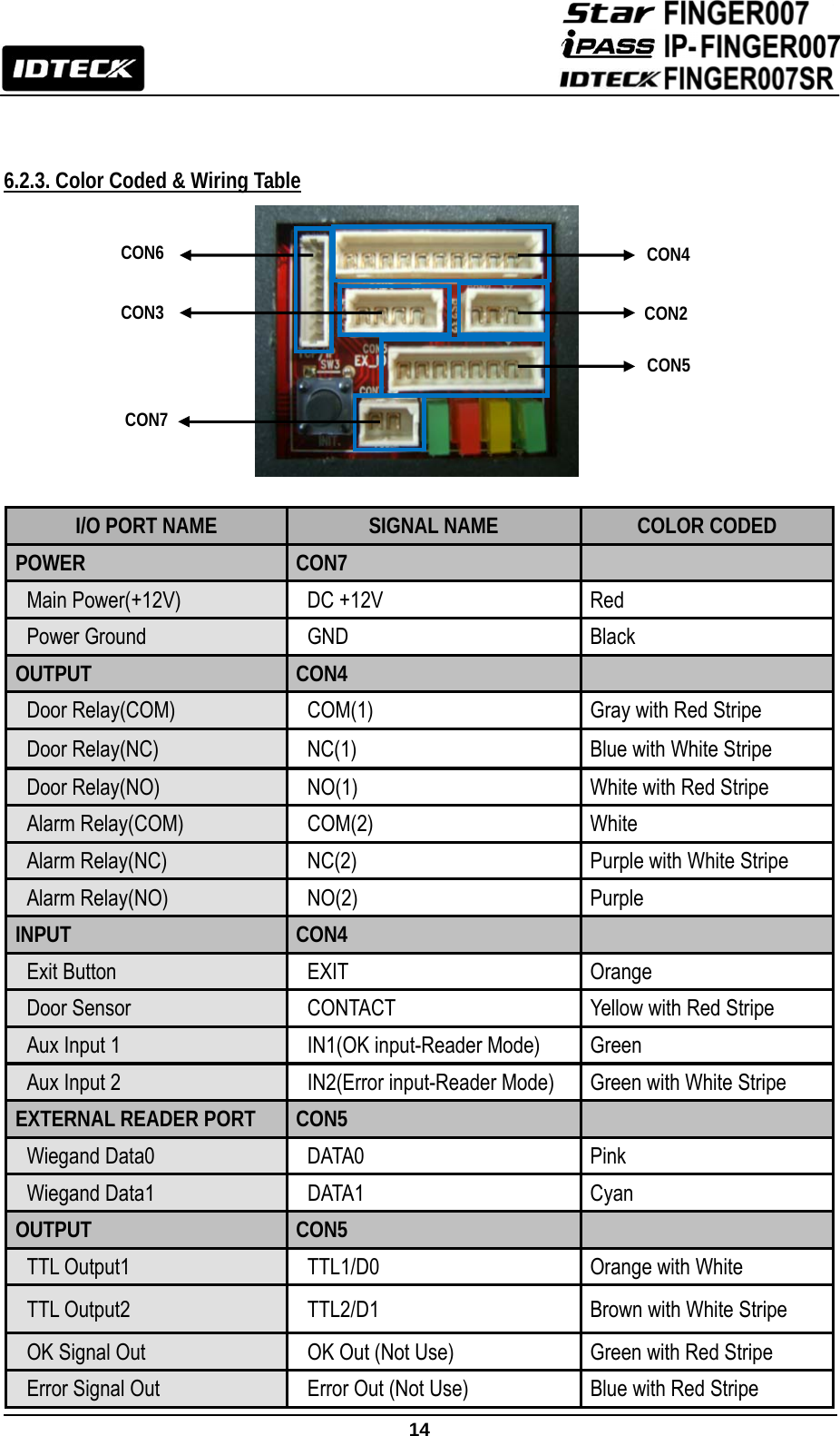
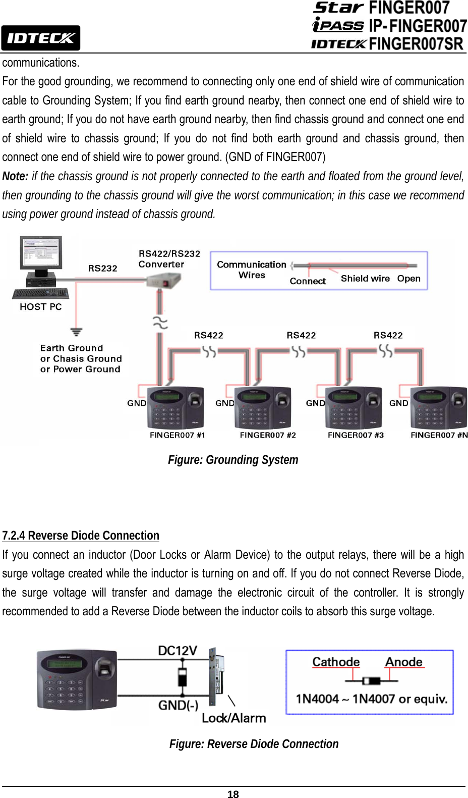
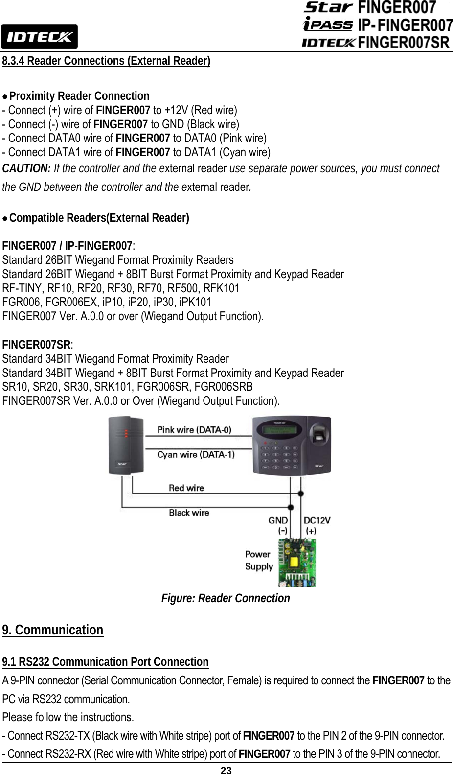
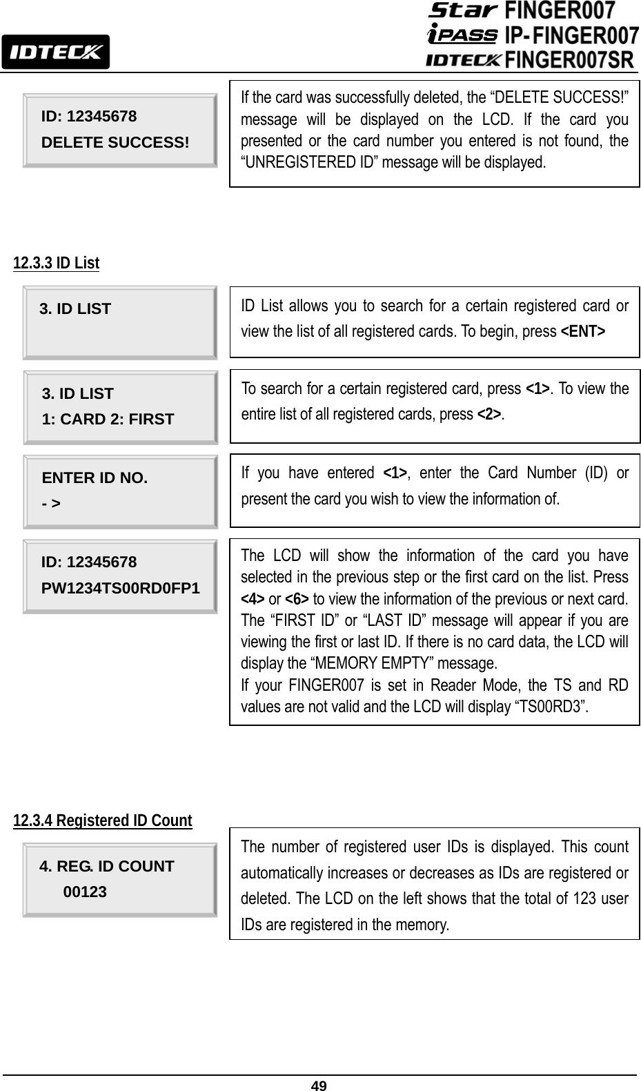
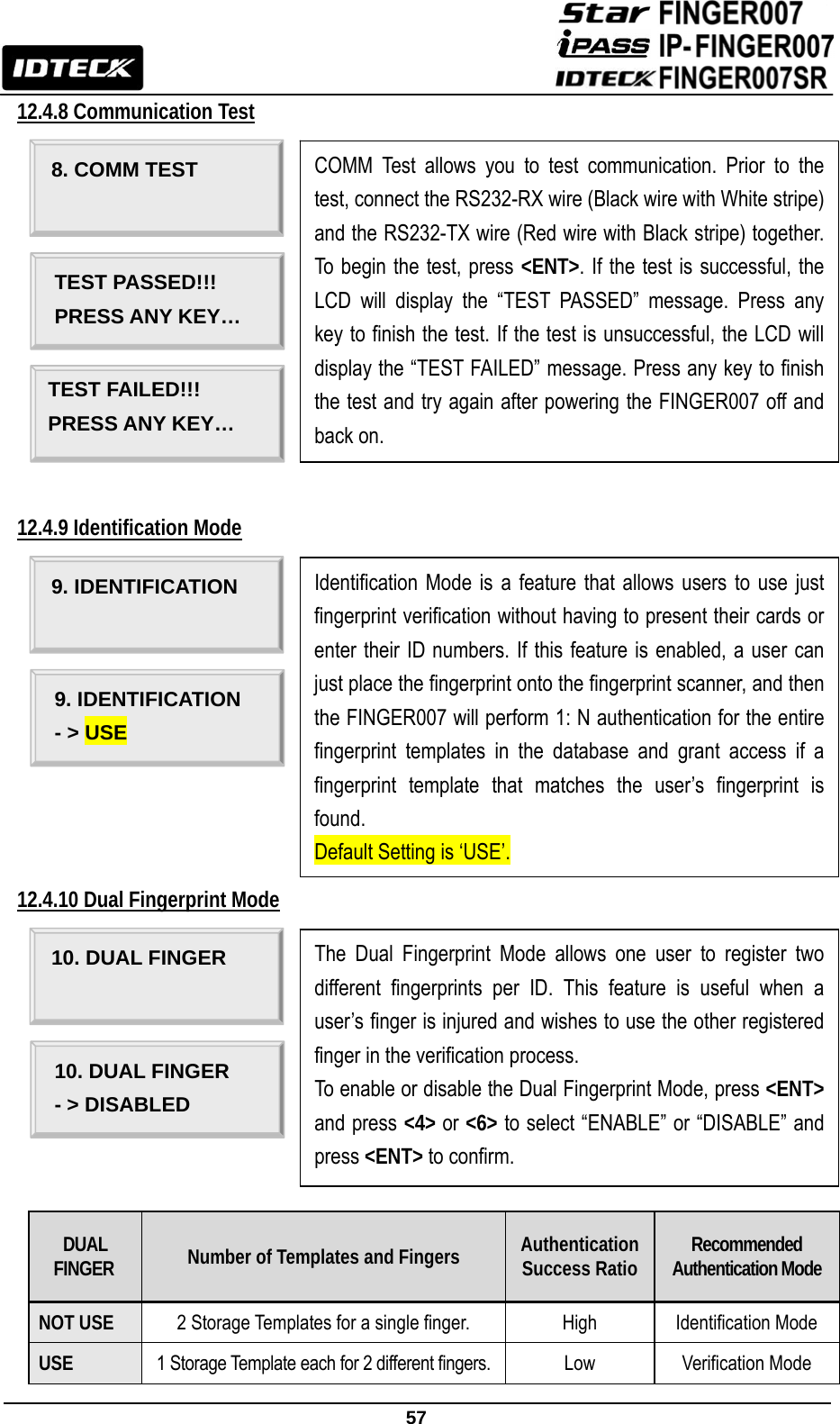
![48 12.3.2 ID Deletion ID: 12345678 PW■__TS__RD_FP_ TO REGISTER F/P PUT YOUR FINGER! Once the Card Number is entered, enter the Password (PW), Time Schedule (TS), Reader Number (RD) and Use of Fingerprint (FP) and press <ENT>. For more information, see below. If you have entered 1 in the FP field, the fingerprint scanner will be lit up. Then, place the cardholder’s fingerprint on the scanner. LIFT AND PUT YOUR FINGER! Once the light from the fingerprint scanner is turned off, lift the finger up and put it back on a while later. [Q1:3] [Q2:4] REGISTRATION OK! If the registration is successful, the “REGISTRATION OK!” message will be displayed on the LCD. If you have registered the fingerprint, the quality score for the fingerprint will appear as shown on the left. If the registration is not successful, the “REGISTRATION ERR!” Message will be displayed on the LCD. Description of Fields z PW (Password): Enter the 4Digit password. Password verification can be enabled in 11.1.4. Reader1 Mode. This field is compulsory even if you do not use password verification. z TS (Time Schedule): If you wish to apply a certain time schedule to the cardholder, enter the T/S code. If you wish to allow the cardholder round-the-clock access, enter 0. z RD (Reader Assignment Code): To use both Readers1 and 2 for the cardholder. Enter 0(or 3). To use just Reader1, enter1. To use just Reader2, enter2. z FP (Fingerprint): To register the cardholder’s fingerprint, enter1. If you do not wish to register the cardholder’s fingerprint, enter 0. 2.ID DELETE ENTER ID NO. - > ID Delete allows you to delete existing cards from the FINGER007. To delete an existing card (Or ID), press <ENT>. Either present a card you wish to delete to the FINGER007 or enter the card number (ID) via the keypad and press <ENT>.](https://usermanual.wiki/ID-Teck-Co/FINGER007SR/User-Guide-1574254-Page-49.png)
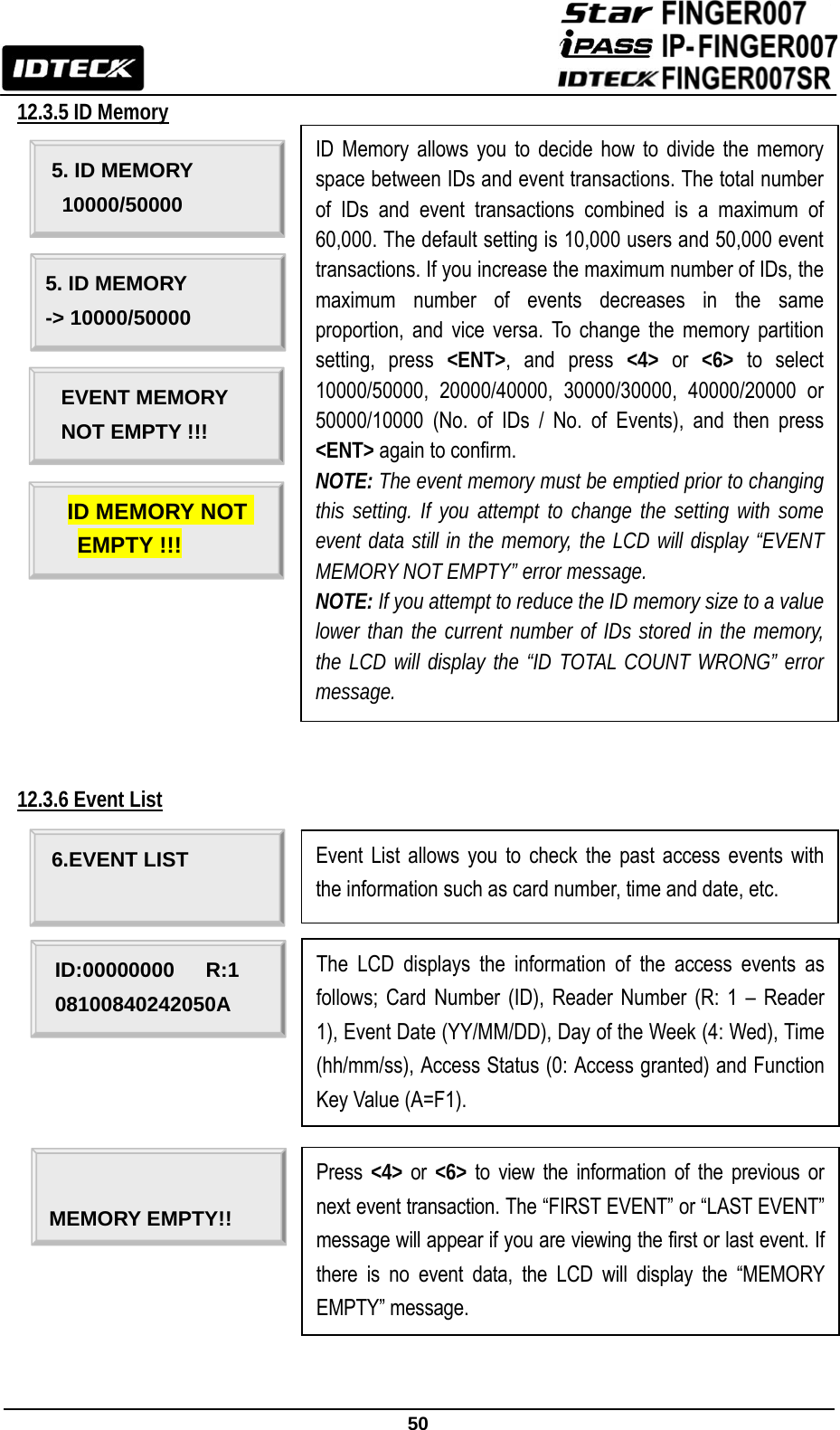
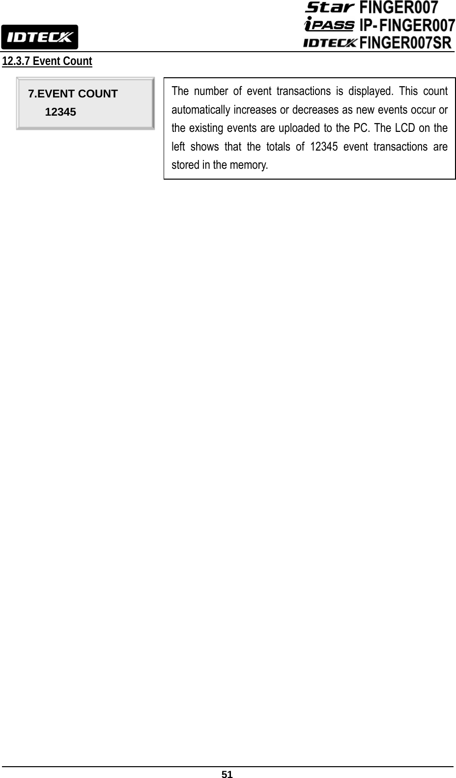
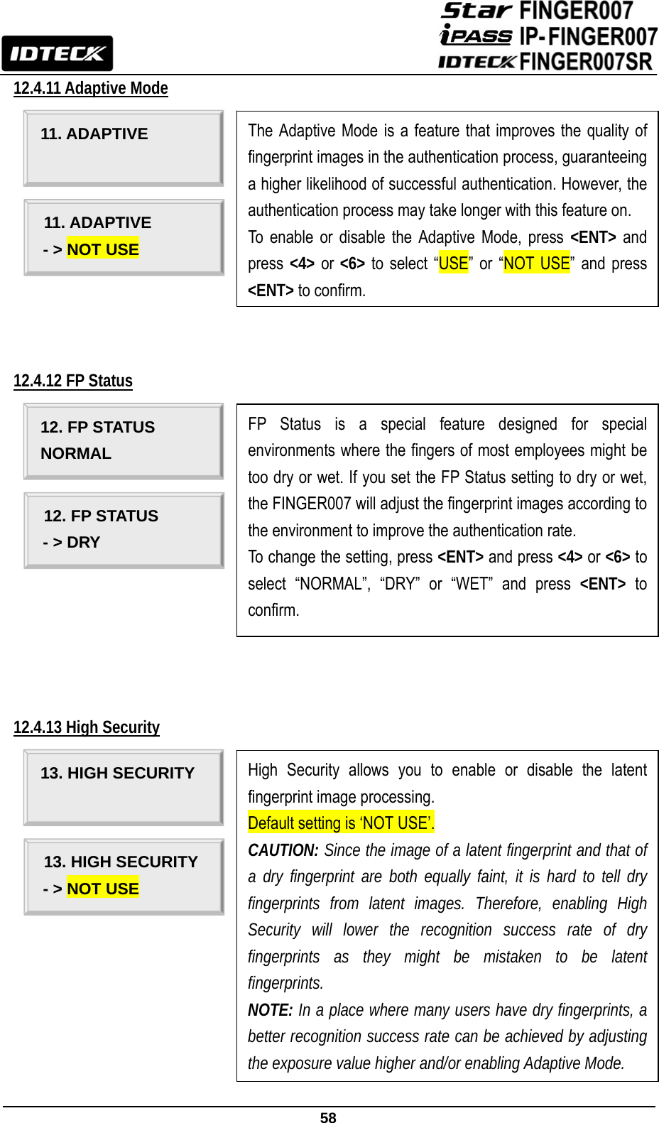

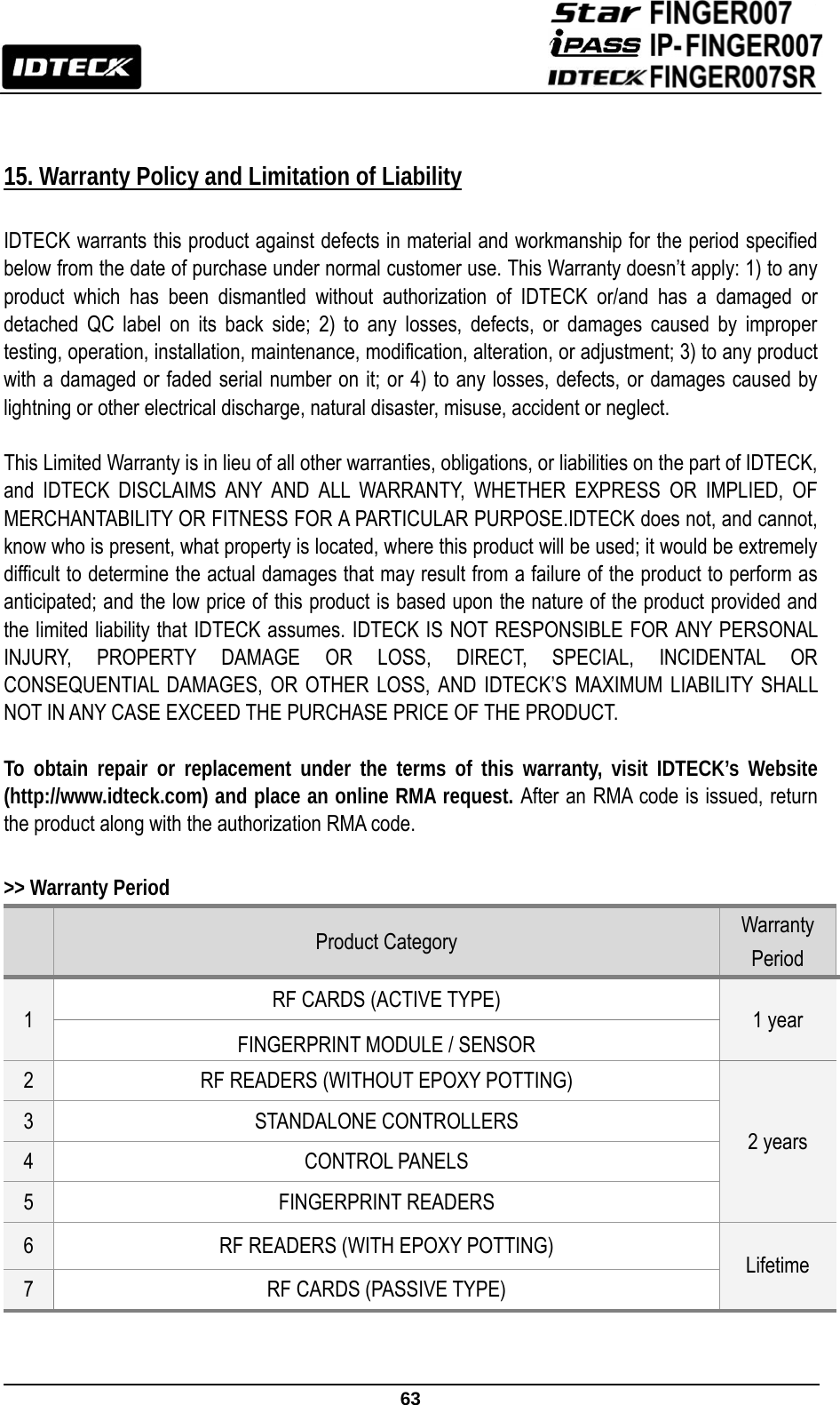
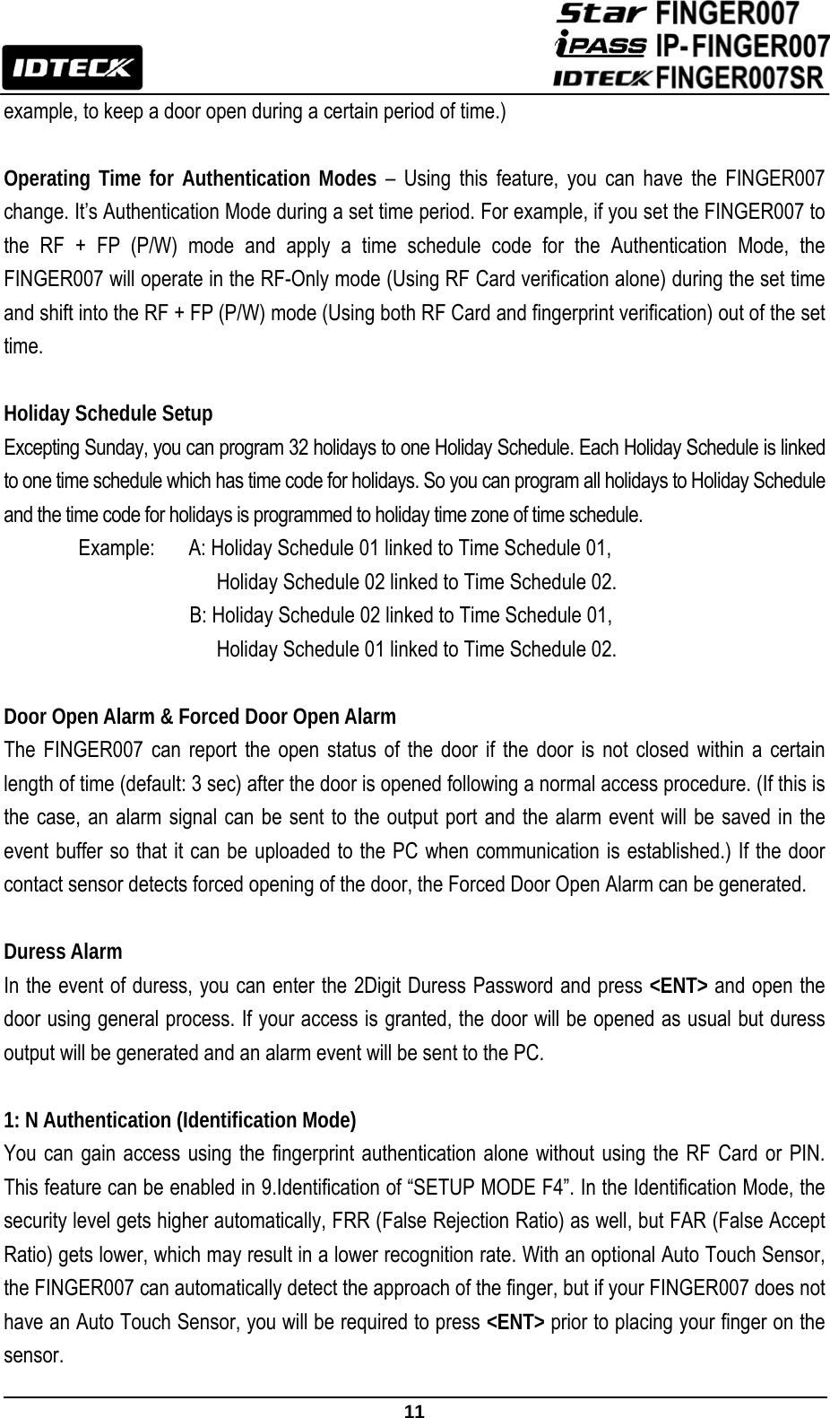
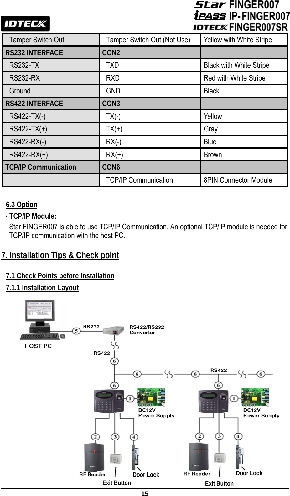
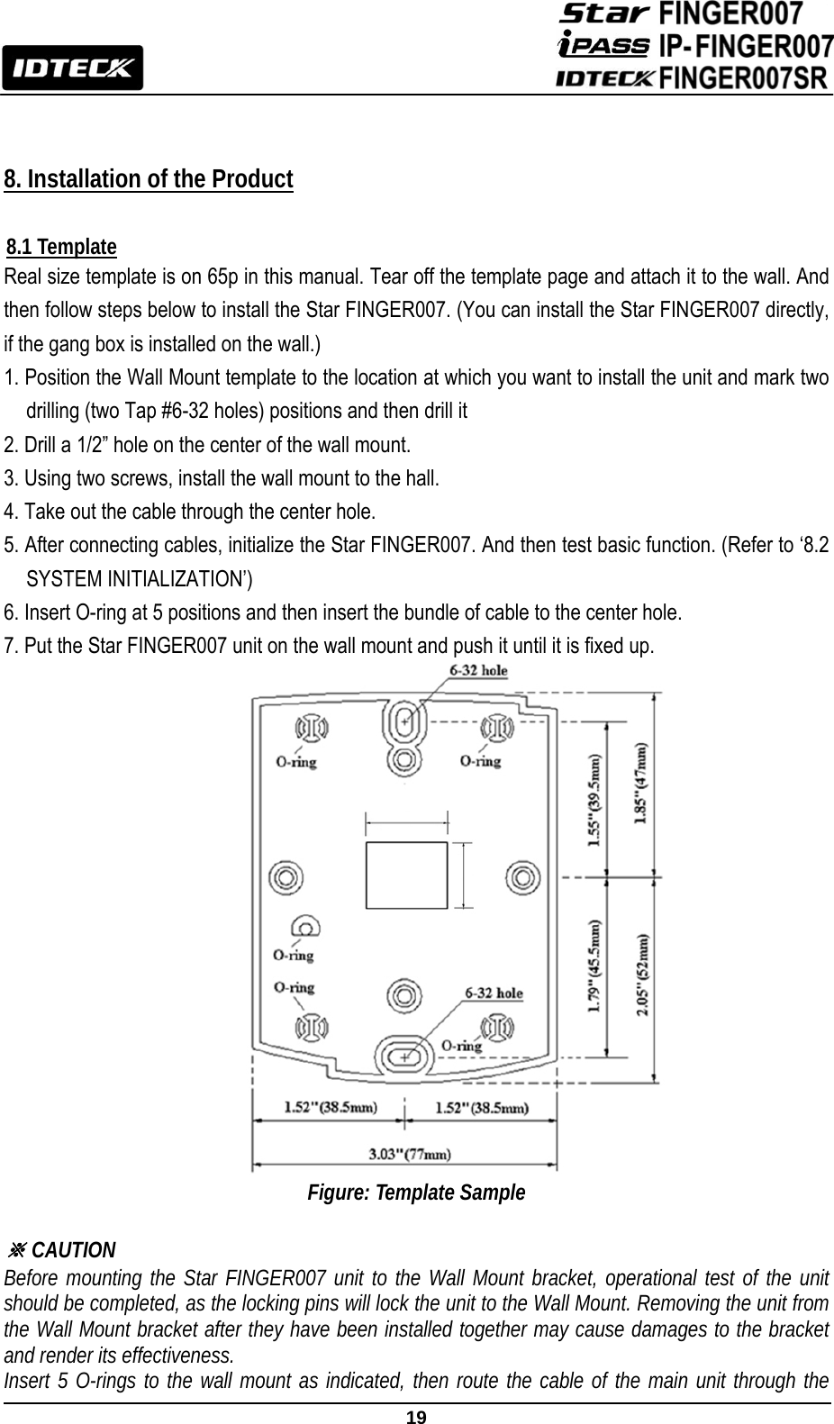
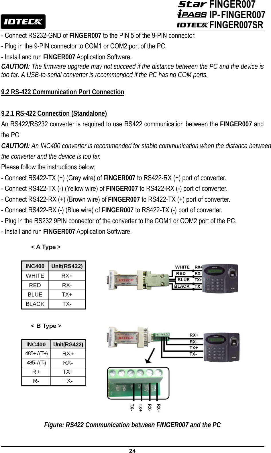
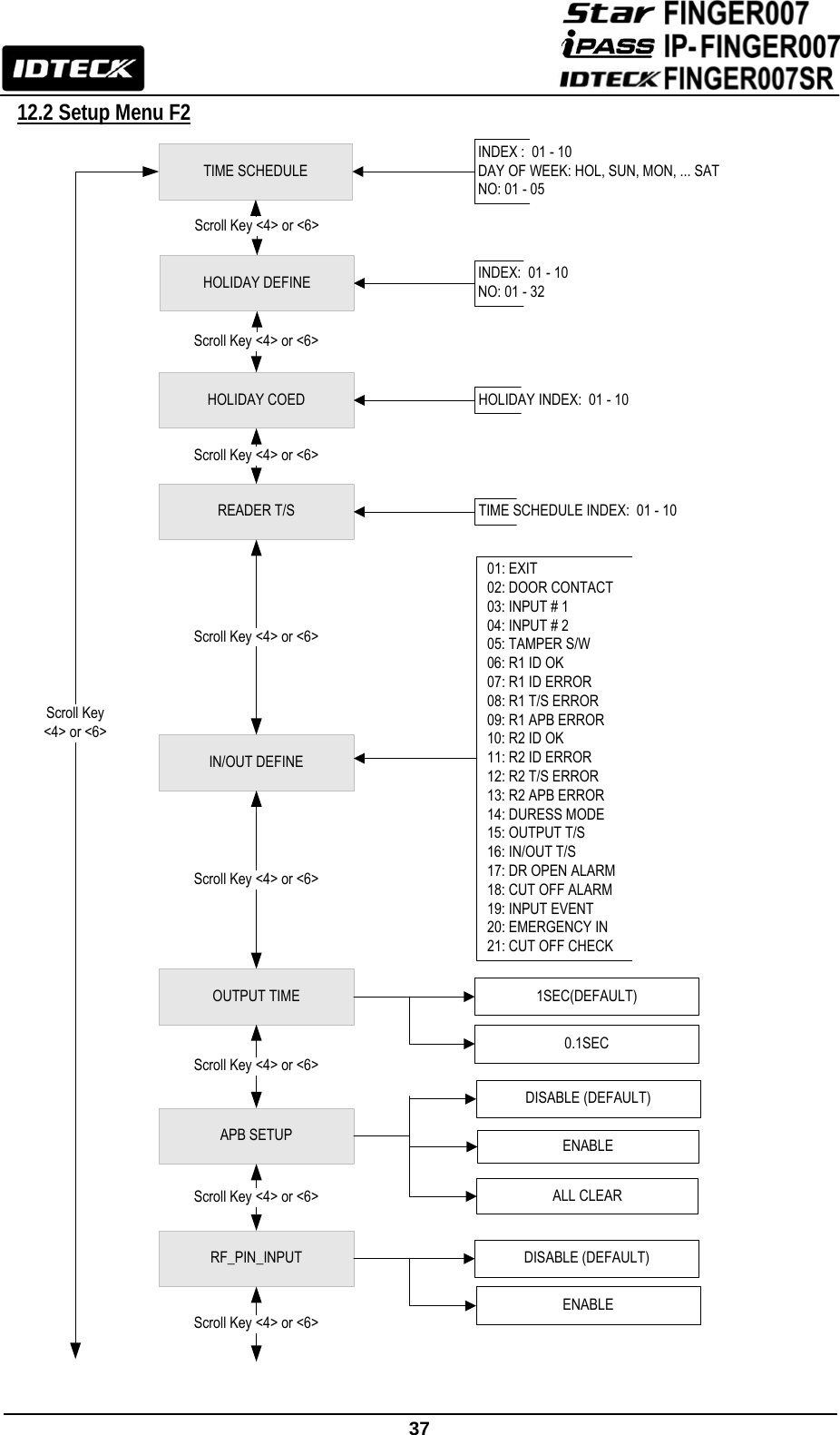
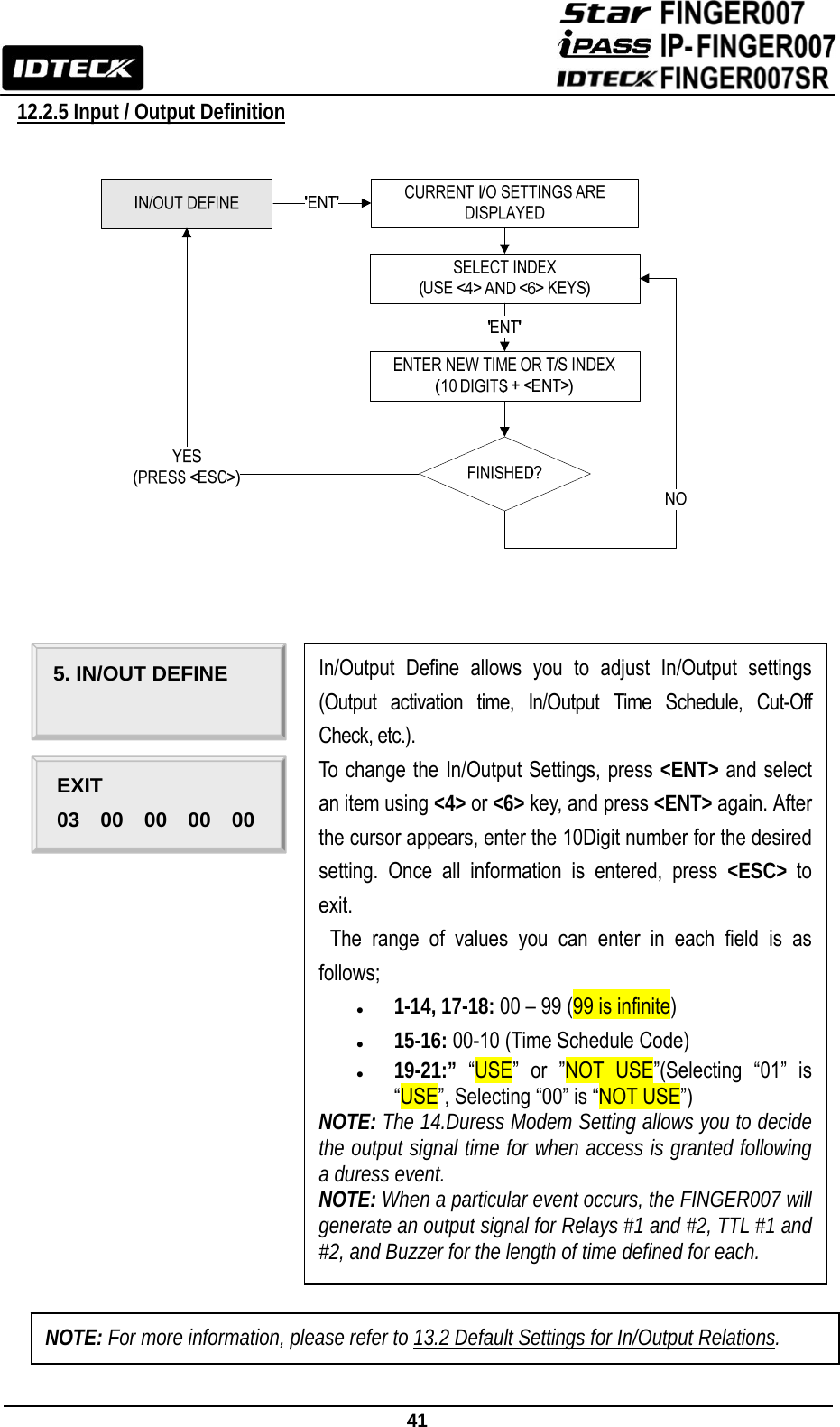
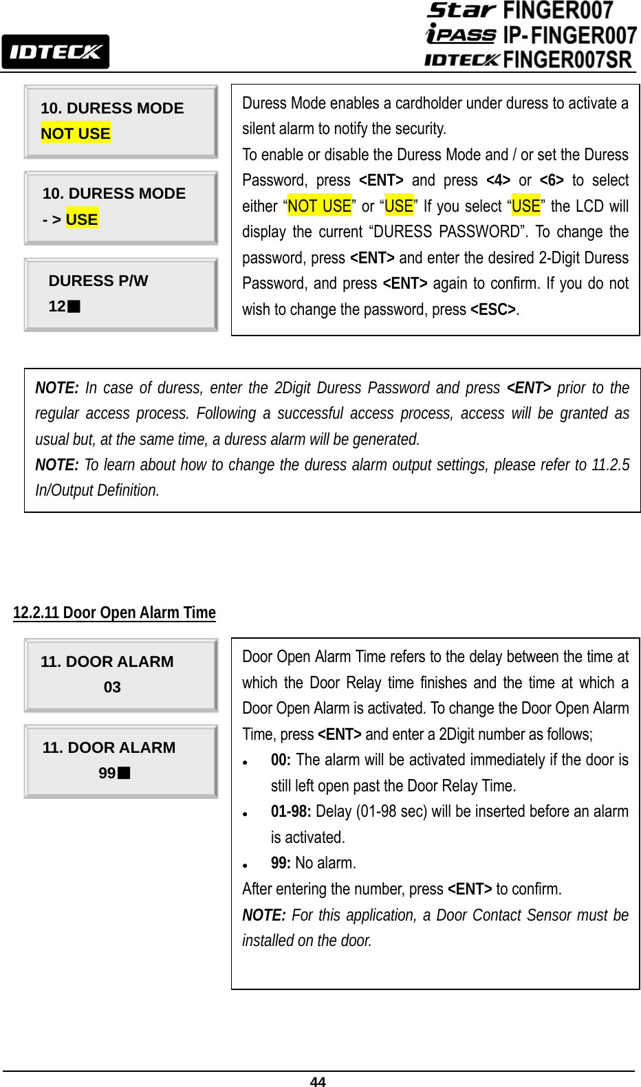
![61 13.2 Default Output Settings for Input / Output Relations OUTPUT INPUT Relay#1 Relay#2 TTL#1 TTL#2 BUZZER [1] Input #1(EXIT BUTTON) 03 00 00 00 00 [2] Input #2(Door Contact SW) 00 99 00 00 99 [3] Input #3 00 00 00 00 00 [4] Input #4 00 00 00 00 00 [5] Input #5(TAMPER S/W) 00 99 00 00 99 [6] Reader#1 ID OK 03 00 00 00 00 [7] Reader#1 ID Error 00 03 00 00 00 [8] Reader#1 ID T/S Error 00 03 00 00 00 [9] Reader#1 APB Error 00 03 00 00 00 [10] Reader#2 ID OK 03 00 00 00 00 [11] Reader#2 ID Error 00 03 00 00 00 [12] Reader#2 ID T/S Error 00 03 00 00 00 [13] Reader#2 APB Error 00 03 00 00 00 [14] DURESS MODE 03 00 00 00 00 [15] OUTPUT TIME SCHEDULE 00 00 00 00 00 [16] INPUT TIME SCHEDULE Input #1 Input #2 Input #3 Input #4 Input #5 00 00 00 00 00 [17] DR OPEN ALARM Relay#1 Relay#2 TTL#1 TTL#2 BUZZER 00 03 00 00 00 [18] CUT OFF ALARM Relay#1 Relay#2 TTL#1 TTL#2 BUZZER 00 03 00 00 00 [19] INPUT EVENT Input #1 Input #2 Input #3 Input #4 Input #5 01 01 01 01 01 [20] EMERGENCY IN Input #1 Input #2 Input #3 Input #4 Input #5 00 00 00 00 00 [21] CUT OFF CHECK Input #1 Input #2 Input #3 Input #4 Input #5 00 00 00 00 00 * Index No. [1] - [14], [17]-[18] The values indicate the operating time of each output for the input signal. 99 denote “Operating time is not limited”. * Index No. [15] The values indicate the Time Schedule Code (index) applied to each output.](https://usermanual.wiki/ID-Teck-Co/FINGER007SR/User-Guide-1574254-Page-62.png)
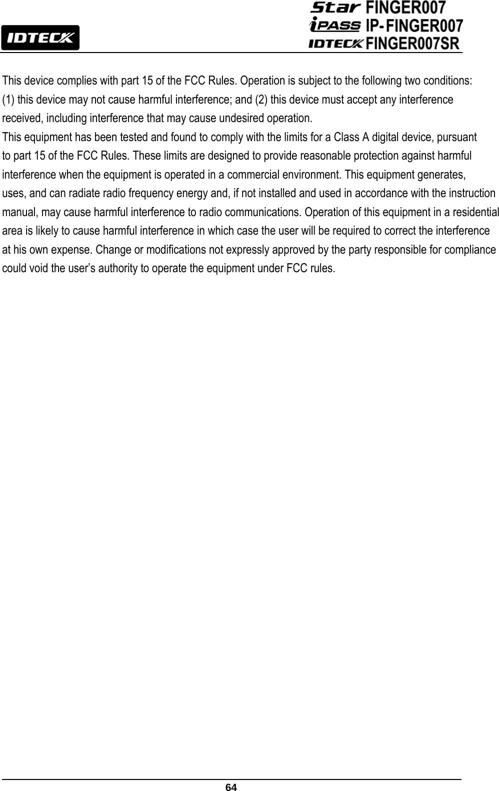
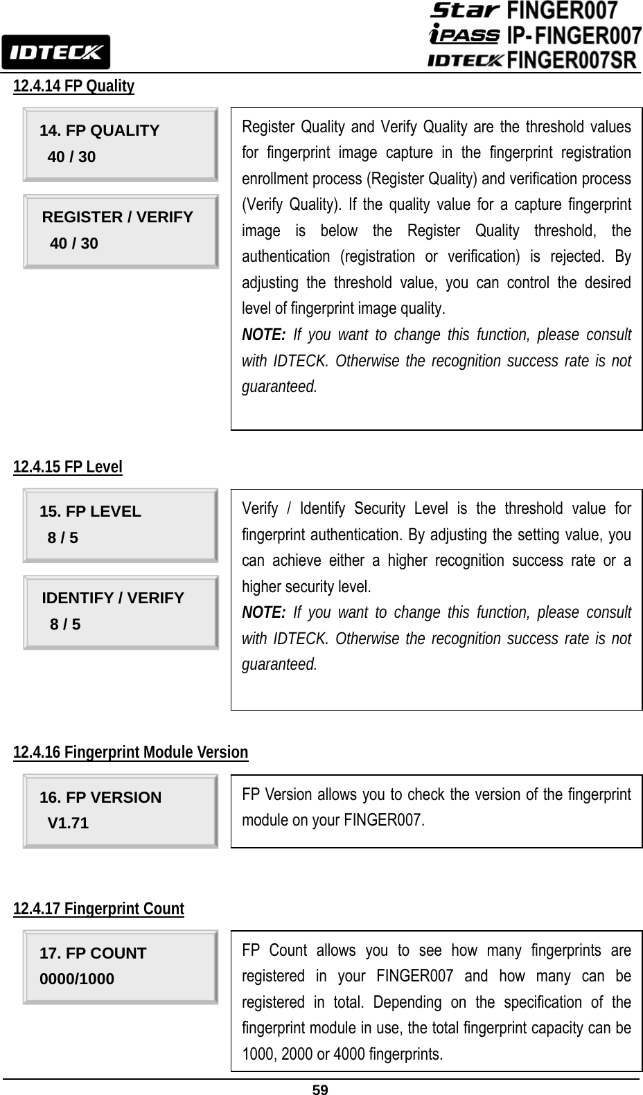
![62 * Index No. [16] The values indicate the Time Schedule Code (index) applied to each input. * Index No. [19]-[21] The values indicate whether to enable or disable the feature for each output. (01-USE, 00-NOT USE) 14. FCC Registration Information FCC Requirements Part 15 CAUTION: Any changes or modifications in construction of this device which are not expressly approved by the responsible for compliance could void the user's authority to operate the equipment. NOTE: This device complies with Part 15 of the FCC rules. Operation is subject to the following two conditions; 1. This device may not cause harmful interface, and 2. This device must accept any interference received, including interference that may cause undesired operation. This equipment has been tested and found to comply with the limits for a Class A Digital Device, pursuant to Part 15 of the FCC rules. These limits are designed to this equipment generates, uses, and can radiate radio frequency energy and, if not installed and used in accordance with the instructions, may cause harmful interference to radio communications. However, there is no guarantee that interference will not occur in a particular installation. If this equipment does cause harmful interference to radio or television reception, which can be determined by turning the radio or television off and on, the user is encouraged to try to correct interference by one or more of the following measures. 1. Reorient or relocate the receiving antenna. 2. Increase the separation between the equipment and receiver. 3. Connect the equipment into an outlet on another circuit. 4. Consult the dealer or an experienced radio/TV technician for help.](https://usermanual.wiki/ID-Teck-Co/FINGER007SR/User-Guide-1574254-Page-63.png)