ID Teck Co FINGER007SR RFID & Biometrics Access Controller User Manual Appendix 4 Block Diagram
ID-Teck Co Ltd RFID & Biometrics Access Controller Appendix 4 Block Diagram
User Manual

http://www.emc2000.co.kr
FCC TEST REPORT
Report No.: EMC-FCC-R0049
EMC compliance Ltd.
82-1, JEIL-RI, YANGJI-MYUN, CHURINGU, YONGIN-CITY, KYUNGGI-DO, KOREA 449-825
82 31 336 9919 (Main) 82 31 336 4767 (Fax)
This test report shall not be reproduced except in full, Without the written approval.
Appendix 6.
User manual

User’s Manual
Fingerprint Identification
Access Control System

2
Table of Contents
1. Safety Instructions .............................................................................................................. 5
2. General ................................................................................................................................. 6
3. Key Features ........................................................................................................................ 7
4. Specifications ...................................................................................................................... 7
5. Identifying Supplied Parts .................................................................................................. 9
6. Product Overview ................................................................................................................ 9
6.1. Functions ....................................................................................................................... 9
6.2 Product Description ...................................................................................................... 12
6.2.1 Front View ............................................................................................................. 12
6.2.2 Rear View .............................................................................................................. 13
6.2.3. Color Coded & Wiring Table ................................................................................. 14
6.3 Option ........................................................................................................................... 15
7. Installation Tips & Check point ........................................................................................ 15
7.1 Check Points before Installation ................................................................................... 15
7.1.1 Installation Layout .................................................................................................. 15
7.1.2 Recommended Cable Type ................................................................................... 16
7.2 Check Point during Installation ..................................................................................... 16
7.2.1 Termination Resistor .............................................................................................. 16
7.2.2 How to Connect Termination Resistors .................................................................. 17
7.2.3 Grounding System for Communication Cable ........................................................ 17
7.2.4 Reverse Diode Connection .................................................................................... 18
8. Installation of the Product ................................................................................................ 19
8.1 Template ....................................................................................................................... 19
8.2 System Initialization ...................................................................................................... 20
8.3 Wiring............................................................................................................................ 21
8.3.1 Power .................................................................................................................... 21
8.3.2 Input Connections .................................................................................................. 21
8.3.3 Output Connections ............................................................................................... 22
8.3.4 Reader Connections (External Reader) ................................................................. 23
9. Communication ................................................................................................................... 23
9.1 RS232 Communication Port Connection ...................................................................... 23
9.2 RS-422 Communication Port Connection ..................................................................... 24
9.2.1 RS-422 Connection (Standalone) .......................................................................... 24
9.2.2 RS-422 Connection (Multiple FINGER007 Connections) ...................................... 25

3
9.3 TCP/IP Communication Port Connection (Optional) ..................................................... 25
9.4 TCP/IP Converter (External Version) ............................................................................ 26
10. Initial Setup ...................................................................................................................... 27
10.1 Initialization of FINGER007 ......................................................................................... 27
10.2 Entering Setup Mode .................................................................................................. 27
10.3 Time / Date Setting ..................................................................................................... 28
10.4 Setting Maximum Number of Cardholder IDs ............................................................. 28
10.5 Registering Cardholder IDs ......................................................................................... 29
11. Operation ......................................................................................................................... 29
11.1 Normal Operation ........................................................................................................ 29
11.2 Default Setting ............................................................................................................ 30
12. Setting Changes .............................................................................................................. 31
12.1 Setup Menu F1 ........................................................................................................... 32
12.1.1. Time Setting ....................................................................................................... 32
12.1.2. Communication Address ..................................................................................... 33
12.1.3. Baud Rate .......................................................................................................... 33
12.1.4. Reader1 Mode .................................................................................................... 34
12.1.5. Reader 2 Mode ................................................................................................... 34
12.1.6. Master ID Registration ........................................................................................ 35
12.1.7. System Initialization ............................................................................................ 35
12.1.8. Card ID Clear...................................................................................................... 36
12.1.9. Event Clear ......................................................................................................... 36
12.1.10. Time Schedule Clear ........................................................................................ 36
12.2 Setup Menu F2 ............................................................................................................ 37
12.2.1 Time Schedule ..................................................................................................... 38
12.2.2 Holiday Time Schedule ........................................................................................ 39
12.2.3 Holiday Code ....................................................................................................... 40
12.2.4 Reader Time Schedule ........................................................................................ 40
12.2.5 Input / Output Definition ....................................................................................... 41
12.2.6 Output Time Setting ............................................................................................. 42
12.2.7 Anti-Pass Back .................................................................................................... 42
12.2.8 RF PIN Input ........................................................................................................ 43
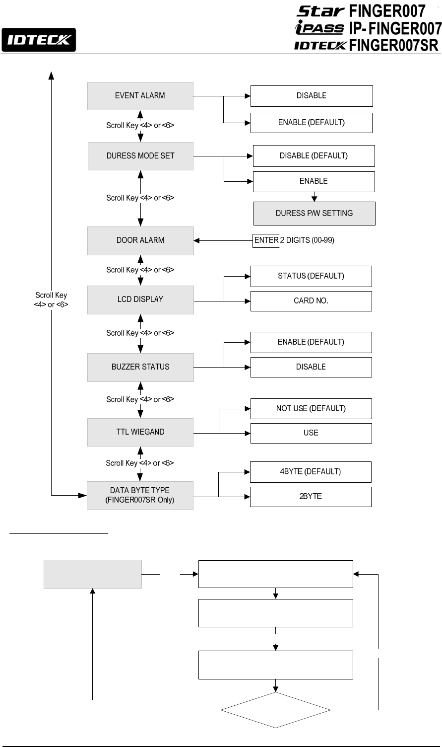
12.2.9 Event Alarm ......................................................................................................... 43
12.2.10 Duress Mode ..................................................................................................... 43
12.2.11 Door Open Alarm Time ...................................................................................... 44
12.2.12 LCD Display....................................................................................................... 45
12.2.13 Buzzer Status .................................................................................................... 45
12.2.14 TTL WEIGAND Output ...................................................................................... 45

4
12.3 Setup Menu F3 ........................................................................................................... 47
12.3.1 ID Registration ..................................................................................................... 47
12.3.2 ID Deletion ........................................................................................................... 48
12.3.3 ID List .................................................................................................................. 49
12.3.4 Registered ID Count ............................................................................................ 49
12.3.5 ID Memory ........................................................................................................... 50
12.3.6 Event List ............................................................................................................. 50
12.3.7 Event Count ......................................................................................................... 51
12.4 Setup Menu F4 ........................................................................................................... 52
12.4.1 Firmware Version ................................................................................................. 54
12.4.2 Memory Test ........................................................................................................ 54
12.4.3 Output Test .......................................................................................................... 54
12.4.4 LCD Test .............................................................................................................. 55
12.4.5 Keypad Test ......................................................................................................... 55
12.4.6 Reader Test ......................................................................................................... 56
12.4.7 Input / DIP Switch Test ......................................................................................... 56
12.4.8 Communication Test ............................................................................................ 57
12.4.9 Identification Mode .............................................................................................. 57
12.4.10 Dual Fingerprint Mode ....................................................................................... 57
12.4.11 Adaptive Mode ................................................................................................... 58
12.4.12 FP Status ........................................................................................................... 58
12.4.13 High Security ..................................................................................................... 58
12.4.14 FP Quality .......................................................................................................... 59
12.4.15 FP Level ............................................................................................................ 59
12.4.16 Fingerprint Module Version ................................................................................ 59
12.4.17 Fingerprint Count ............................................................................................... 59
12.4.18 Fingerprint Module Test ..................................................................................... 60
12.4.19 Fingerprint Device Information Check ............................................................... 60
13. Appendix .......................................................................................................................... 60
13.1 Default Values for Parameters .................................................................................... 60
13.2 Default Output Settings for Input / Output Relations ................................................... 61
14. FCC Registration Information ........................................................................................ 62
15. Warranty Policy and Limitation of Liability ................................................................... 63
16. How to Make RMA Request (After Sales Service) ........................................................ 65
17. Template ........................................................................................................................... 66
5
1. Safety Instructions
The description below is to keep user’s safety and prevent any product damage. Please fully
read these instruction and use the product properly.
Danger: This symbol indicates that incorrect handling of the product may
result in serious injury or death.
Warning: This symbol indicates that incorrect handling of the product
may result in injury or property damage.
- Only use the standard voltage (DC +12V/ 350mA).
- If the product emits smoke or smells, stop using the product. Unplug the product from DC power
source and contact nearest service center.
- Do not install the product in a place subject to humidity, dust (metallic dust) or splashing water
(raindrops).
- Do not install the product in a place not meeting the operating humidity and temperature
specified in the specification.
- Do not install the product with tools such as driver in hand when power is being supplied.
- Do not drop liquid like water and give a shock severely.
- Do not place magnetic objects near the product.
- Do not replace the wiring cables installed by experts.
- Do not use the product near direct sunlight and heating apparatus.
- If you want to relocate the installed product, turn power off and then move and reinstall it.
- Do not use the product near flammable spray or objects.
- Do not disassemble, repair or modify the product by yourself. If the product needs service or
repair, contact nearest service center.
- If liquid has been spilled on the product, unplug it and contact nearest service center.
- Do not clean the product with water. Clean gently with dry cloth or towel.
- Do not use chemicals such as benzene, thinner or acetone for cleaning.
Cautions about Installation
Cautions about Power
Cautions about Usage
Cautions about Cleaning

6
2. General
The Star FINGER007 / iPASS IP-FINGER007 / IDTECK FINGER007SR is a highly advanced
single-door biometric access controller with a fingerprint recognition module, a proximity card reader
and a keypad. The flexible but reliable biometric access controller is designed to meet various
requirements for a robust integrated security solution for access control and time & attendance.
This user-friendly device is capable of storing up to 10,000 to 50,000 cardholders including 1,000 /
2,000 / 4,000 fingerprint users. Depending on the total number of cardholders, up to 10,000 to
50,000 events and alarms can be buffered in the memory so that they can be uploaded to the PC
when communication is established.
With a built-in 4” proximity reader, a keypad for Personal Identification Number (PIN) verification
and a fingerprint recognition module, the state-of-the-art device allows users to use any
combination of proximity card / PIN, password and fingerprint verification, depending on the desired
level of security and convenience for individual users or different groups of users.
The Star FINGER007 / iPASS IP-FINGER007 / IDTECK FINGER007SR is capable of controlling
one External Reader for Anti-Pass Back application. Four independent input ports can be utilized for
a wide variety of applications including Exit Buttons, Door Contacts, PIR Sensors and Fire Detection
equipment. Actions to be taken and time settings can be programmed with the front keypad or via
the intuitive Windows-based software program.
With a built-in 4" RF reader, keypad for Personal Identification Numbers (PIN), and a sophisticated
biometric fingerprint analyzer, the Star FINGER007 / iPASS IP-FINGER007 / IDTECK
FINGER007SR offers up to three levels of ID verification. Any combination of proximity, PIN, and
biometric may be used and different verification levels can be custom programmed for each user or
user group.
The intelligent access controller has the capability to supervise the input and report any
disconnection or malfunction of the input to the host or other devices. Events from high priority input
devices such as Fire Alarm Sensor, Emergency Key, etc. can be reported to the host prior to all
other events. You can use the unit standalone but you can also connect it to the network via RS232
or RS422 communication or on an Ethernet network through an optional TCP/IP module.
The Star FINGER007 / iPASS IP-FINGER007 / IDTECK FINGER007SR has 2 FORM-C Relays
and 2 TTL Output Ports allowing for interface with various other devices such as auto dialers. All
control setting values such as ID numbers, inputs / outputs, Real-Time Clock, Time Schedules, and
Event Transaction Reports can be transferred to and from the PC.

7
3. Key Features
z FINGER007, IP-FINGER007 : 125KHz Proximity / FINGER007SR : 13.56MHz Contactless
Smart Card
z PIN and Fingerprint Recognition
z Dual Function for Access Control and Time & Attendance
z 1:1 Verification and 1: N Identification
z Stores 2 Fingerprint Templates per user
z Auto Touch Sensor for Fingerprint-Only Access
z Supports up to 1,000 / 2,000 / 4,000 Fingerprint Users
z Stores up to 10,000 – 50,000 Users and up to 10,000 – 50,000 Events (Selectable)
z Network Communication via RS232 or RS422 or Ethernet through a Built-in TCP/IP Module
(Optional)
z 4 Supervised Input Ports for Cut-Off Check
z 2 FORM-C Relays and 2 TTL Output Ports
z Duress Alarm Function
z Reader Mode Allows Connection to a Control Panel.
z 26/34Bit Wiegand Output for Reader Mode
z 2 Tamper Switches
z Compatible Software: STARWATCH DUAL PRO I, STARWATCH DUAL PRO II,
STARWATCH STANDARD
4. Specifications
Model FINGER007/ IP-FINGER007/FINGER007SR
CPU 32Bit ARM9 and Dual 8Bit Microprocessor
Memory
Fingerprint
Module
Program
Memory 1MByte flash memory
Data Memory
1MByte / 2MByte / 4MByte flash memory
Controller Program
Memory 128KByte flash memory
Data Memory
1MByte flash memory
Users (Fingerprint Users) 10,000 – 50,000 users
(including 1,000 / 2,000 / 4,000 fingerprint users,
depending on the model)
Event Buffer 10,000 – 50,000 event buffer
(The sum of users and events cannot exceed 60,000.)
Fingerprint Templates Size 800 Bytes for 2 fingerprint templates
Read Range
FINGER007 IDC80 / IDC170 :Up to 4 inches (10cm)
IP-FINGER007
IPC80 / IPC170 :Up to 4 inches (10cm)
FINGER007SR
IHC80 :Up to 2 inches (5cm)
ISC80 :Up to 4 inches (10cm)
8
Reading Time (Card) 30ms
Verification / Identification Time Less than 1sec. / Less than 2sec.
Power / Current DC 12V / Max.300mA
External Reader Port
FINGER007 /
IP-FINGER007
1 port (26bitWiegand, 4 / 8Bit Burst for PIN)
for Anti-Pass Back
FINGER007SR
1 port (34BitWiegand, 4 / 8Bit Burst for PIN)
for Anti-Pass Back
Communication RS232 / RS422 (Max.32ch)
TCP/IP (An optional built-in module or external converter
required)
Baud Rate 9600bps (Recommended) /
4800bps, 19200bps, 38400bps, 57600bps and
115200bps (Selectable)
Input Port 4 ports (Exit Button, Door Sensor, Aux# 1, Aux#2)
Output Port 2 ports (FORM-C Relay Output (COM, NO, NC) /
DC12V~18V, Rating Max.2A)
2 ports (TTL Output / DC5V, Rating Max.20mA)
LCD Character LCD (2 Lines x 16 Char) /
65.6mm x 13.8mm (2.62” x 0.55”) Screen
Keypad 16 Key Numeric Keypad with Back Lighting
LED Indicator 7 Array LED Indicators (Red, Green and Yellow)
Beeper Piezo Buzzer
Operating Temperature 0° to +50°C (+32° to +122°F)
Operating Humidity 10% to 90% relative humidity non-condensing
Color / Material Dark Pearl Gray / Polycarbonate
Dimension (W x H x T) 6.36” x 5.28” x 1.9” (161.5mm x 134mm x 48.5mm)
Weight 525 g (1.15lbs)
Certification FCC, CE, KC, RoHS
* Fingerprint Module Specifications
Resolution 500dpi
Captured Image Size 260 X 300 Pixels
Sensing Area FIM2260 : 15.0mm X 18.5mm
FIM2030 : 13mm X 15.2mm
Scanner High Quality Optical Sensor
FAR(False Acceptance Ratio) 0.001%
FRR(False Reject Ratio) 0.1%
ESD(Electro Static Discharge) ± 6KV (Contact)
Verification Time Less than 1 Sec.
Identification Time Less than 2 Sec.
Color of Scanning LED FIM2260: White / FIM2030: Red

9
5. Identifying Supplied Parts
Unpack and check the contents. If any of these parts are missing, contact your distributor.
Main unit Wall mount O-ring User’s manual Screws Cable & Diode
(1 Unit) (1 PC) (5 PCS) (1 Copy) (4 PCS) Cable(5 ea)
Diode(2 ea)
6. Product Overview
6.1. Functions
Standalone Operation
The Star FINGER007 / iPASS IP-FINGER007 / IDTECK FINGER007SR is capable of having two
readers (i.e. One built-in reader inside the unit and an External Reader connectable using the
External Reader port). The unit receives card data signals from the RF Readers and determines
whether or not to unlock the door. When an input signal is sent, for example from and activated
sensor or if the Exit Button pressed, the controller generates and logs an appropriate response. All
events are kept in its memory and sent to the PC. The access controller is a true standalone device
that in the event of a malfunction, will not affect other units, even if used in conjunction with one
another.
Operation with PC
All event transactions can be managed via the PC. The data transmitted from the controller can be
processed, displayed (In the form of cardholder status, alarm status, etc.) and stored on the PC.
Data Retention
All user information and event/alarm data are retained even in the event of Power Failure unless the
memory or the device itself is damaged.
Keypad
The built-in Keypad and LCD let you perform manual programming without connection to the PC.

10
Dual Finger Mode
Dual Finger Mode is a function that lets a user register two fingers for one ID so that the user can
receive authentication with either of the two registered fingers. This is useful when a user’s finger is
injured.
Anti-Pass Back
Anti-Pass Back is a function that is used to prevent a user entering an area by using their card and
passing that card back to another person to use. If the Anti-Pass Back is applied, cardholders cannot
gain entry or exit twice in a row, and even if someone tailgates someone into the controlled area
without going through the proper authentication procedure, he or she will not be able to gain access
when exiting the area. If this is the case, the FINGER007 generates an error message without
granting access and then stores an Anti-Pass Back error record in the memory. You can also
program the FINGER007 to generate certain output signals in the event of an Anti-Pass Back error.
External Input / Output
The FINGER007 has 4built-in inputs and 4outputs (2Relay Outputs and 2TTL Outputs) which can be
used for a wide variety of purposes and applications. For example, the input ports can be used for
interface with external devices such as Request-To-Exit Button, Fire Detection Sensor, etc. while the
relay output ports can be connected to a Door Lock and/or an Alarm System. When you use
Weigand output function, 26/34BIT Weigand will be generated from dual TTL output.
Time Schedule
You can program 10 Time Schedules and apply one Time Schedule to each user. Each Time
Schedule has 8 different time zones from Monday to Sunday (7 Time Zones) and one holiday. Each
time zone has 5 different time codes so you can program 5 different time codes to each day. Also you
can program Time Schedule for individual inputs and outputs. Note that the Time Schedule for input
is activated time code for input device so that the input is activated during the time code on this Time
Schedule. Each Time Schedule is linked to one of holiday schedule and this linked holiday only
validates to holiday time code of the Time Schedule.
Access Time Limitation for Cardholders – You can assign a time schedule code to each
Cardholder during the card registration process. Cardholders are granted access only during the time
defined in the assigned time schedules. If a Cardholder attempts to gain access out of the set time,
access will be denied with a time schedule error.
Operating Time Limit for Output Ports – If you assign a time schedule code to an output code, the
Output Port generates constant output signals during the set time. (This feature can be used, for

11
example, to keep a door open during a certain period of time.)
Operating Time for Authentication Modes – Using this feature, you can have the FINGER007
change. It’s Authentication Mode during a set time period. For example, if you set the FINGER007 to
the RF + FP (P/W) mode and apply a time schedule code for the Authentication Mode, the
FINGER007 will operate in the RF-Only mode (Using RF Card verification alone) during the set time
and shift into the RF + FP (P/W) mode (Using both RF Card and fingerprint verification) out of the set
time.
Holiday Schedule Setup
Excepting Sunday, you can program 32 holidays to one Holiday Schedule. Each Holiday Schedule is linked
to one time schedule which has time code for holidays. So you can program all holidays to Holiday Schedule
and the time code for holidays is programmed to holiday time zone of time schedule.
Example: A: Holiday Schedule 01 linked to Time Schedule 01,
Holiday Schedule 02 linked to Time Schedule 02.
B: Holiday Schedule 02 linked to Time Schedule 01,
Holiday Schedule 01 linked to Time Schedule 02.
Door Open Alarm & Forced Door Open Alarm
The FINGER007 can report the open status of the door if the door is not closed within a certain
length of time (default: 3 sec) after the door is opened following a normal access procedure. (If this is
the case, an alarm signal can be sent to the output port and the alarm event will be saved in the
event buffer so that it can be uploaded to the PC when communication is established.) If the door
contact sensor detects forced opening of the door, the Forced Door Open Alarm can be generated.
Duress Alarm
In the event of duress, you can enter the 2Digit Duress Password and press <ENT> and open the
door using general process. If your access is granted, the door will be opened as usual but duress
output will be generated and an alarm event will be sent to the PC.
1: N Authentication (Identification Mode)
You can gain access using the fingerprint authentication alone without using the RF Card or PIN.
This feature can be enabled in 9.Identification of “SETUP MODE F4”. In the Identification Mode, the
security level gets higher automatically, FRR (False Rejection Ratio) as well, but FAR (False Accept
Ratio) gets lower, which may result in a lower recognition rate. With an optional Auto Touch Sensor,
the FINGER007 can automatically detect the approach of the finger, but if your FINGER007 does not
have an Auto Touch Sensor, you will be required to press <ENT> prior to placing your finger on the
sensor.
12
Adaptive Mode
If the Adaptive Mode is enabled, the fingerprint image is automatically adapted for better recognition
results. This mode can be enabled in 11.Adaptive of “SETUP MENU F1”. While this feature improves
the recognition success rate, the authentication process may take longer.
Weigand Output Function
You can use a Weigand Output Function in the "SETUP MODE F2".
6.2 Product Description
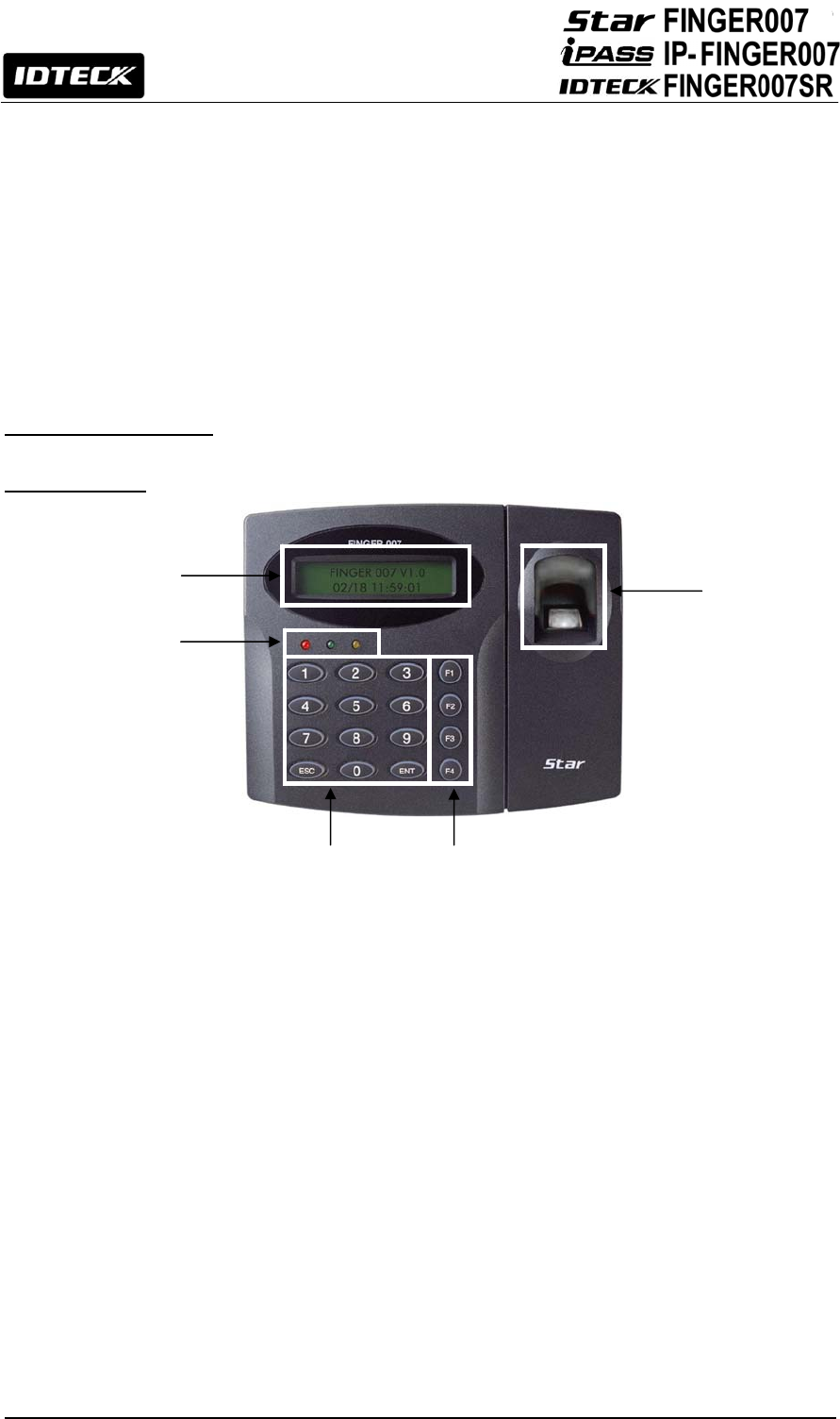
6.2.1 Front View
○
1 LCD Display
It shows setting status.
○
2 3 LED Indicators
It shows system status.
The red LED turns on with power supply.
The green LED turns on with Relay #1 operation.
The yellow LED turns on with Relay #2 operation.
○
3 16 Numeric Keypad
Register/Delete card data and set functions through keypad input.
○
4 Function Keypad
There are four function keys, F1, F2, F3 and F4
○
5 Finger Print Scanner
When users put their finger on the scanner, *white light will turn on.
○
1
○
3
○
5
○
2
○
4
13
*In case of FIM2030, red light will turn on.
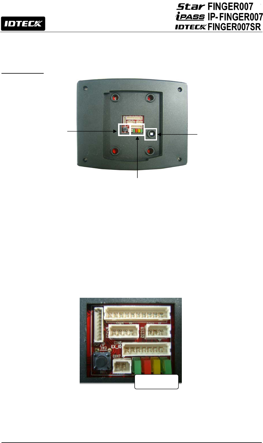
6.2.2 Rear View
○
1 Initialization Switch
This switch is used to initialize Star FINGER007. For initialization, press down this
switch and then keep it more than 2 seconds. Refer to ‘8.2 System Initialization’ for
more details.
○
2 Communication Display LED
#3, #4(yellow, green) LED will twinkle during RS232, RS422 and TCP/IP
communication.
If the LAN is connected normally during TCP/IP communication, #1, green LED will
turn on. But in the collision status, #2, red LED turns on.
Figure: Magnification of the Communication Display LED in the Rear Panel
○
3 Tamper Switch
If someone takes off Star FINGER007 installed on the wall by force, the tamper switch
is activated then buzzer makes sound to inform of theft.
○
2
○
1 ○
3
1 2 3 4
14
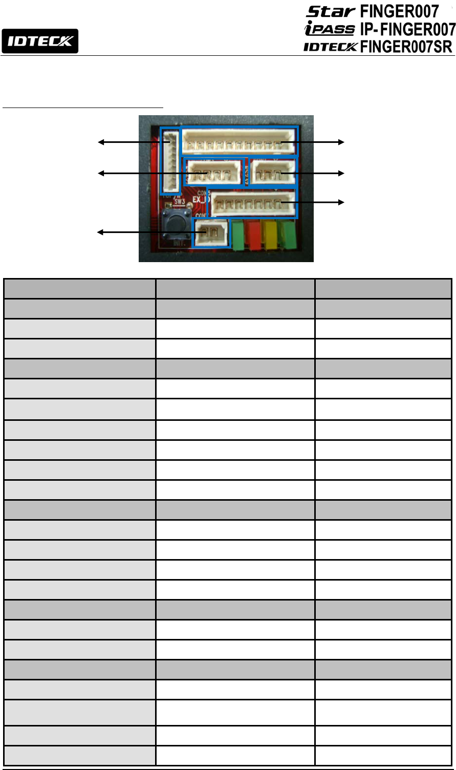
6.2.3. Color Coded & Wiring Table
I/O PORT NAME SIGNAL NAME COLOR CODED
POWER CON7
Main Power(+12V) DC +12V Red
Power Ground GND Black
OUTPUT CON4
Door Relay(COM) COM(1) Gray with Red Stripe
Door Relay(NC) NC(1) Blue with White Stripe
Door Relay(NO) NO(1) White with Red Stripe
Alarm Relay(COM) COM(2) White
Alarm Relay(NC) NC(2) Purple with White Stripe
Alarm Relay(NO) NO(2) Purple
INPUT CON4
Exit Button EXIT Orange
Door Sensor CONTACT Yellow with Red Stripe
Aux Input 1 IN1(OK input-Reader Mode) Green
Aux Input 2 IN2(Error input-Reader Mode) Green with White Stripe
EXTERNAL READER PORT CON5
Wiegand Data0 DATA0 Pink
Wiegand Data1 DATA1 Cyan
OUTPUT CON5
TTL Output1 TTL1/D0 Orange with White
TTL Output2 TTL2/D1 Brown with White Stripe
OK Signal Out OK Out (Not Use) Green with Red Stripe
Error Signal Out Error Out (Not Use) Blue with Red Stripe
CON7
CON5
CON2
CON4
CON3
CON6
15
Tamper Switch Out Tamper Switch Out (Not Use) Yellow with White Stripe
RS232 INTERFACE CON2
RS232-TX TXD Black with White Stripe
RS232-RX RXD Red with White Stripe
Ground GND Black
RS422 INTERFACE CON3
RS422-TX(-) TX(-) Yellow
RS422-TX(+) TX(+) Gray
RS422-RX(-) RX(-) Blue
RS422-RX(+) RX(+) Brown
TCP/IP Communication CON6
TCP/IP Communication 8PIN Connector Module
6.3 Option
TCP/IP Module:
Star FINGER007 is able to use TCP/IP Communication. An optional TCP/IP module is needed for
TCP/IP communication with the host PC.
7. Installation Tips & Check point
7.1 Check Points before Installation
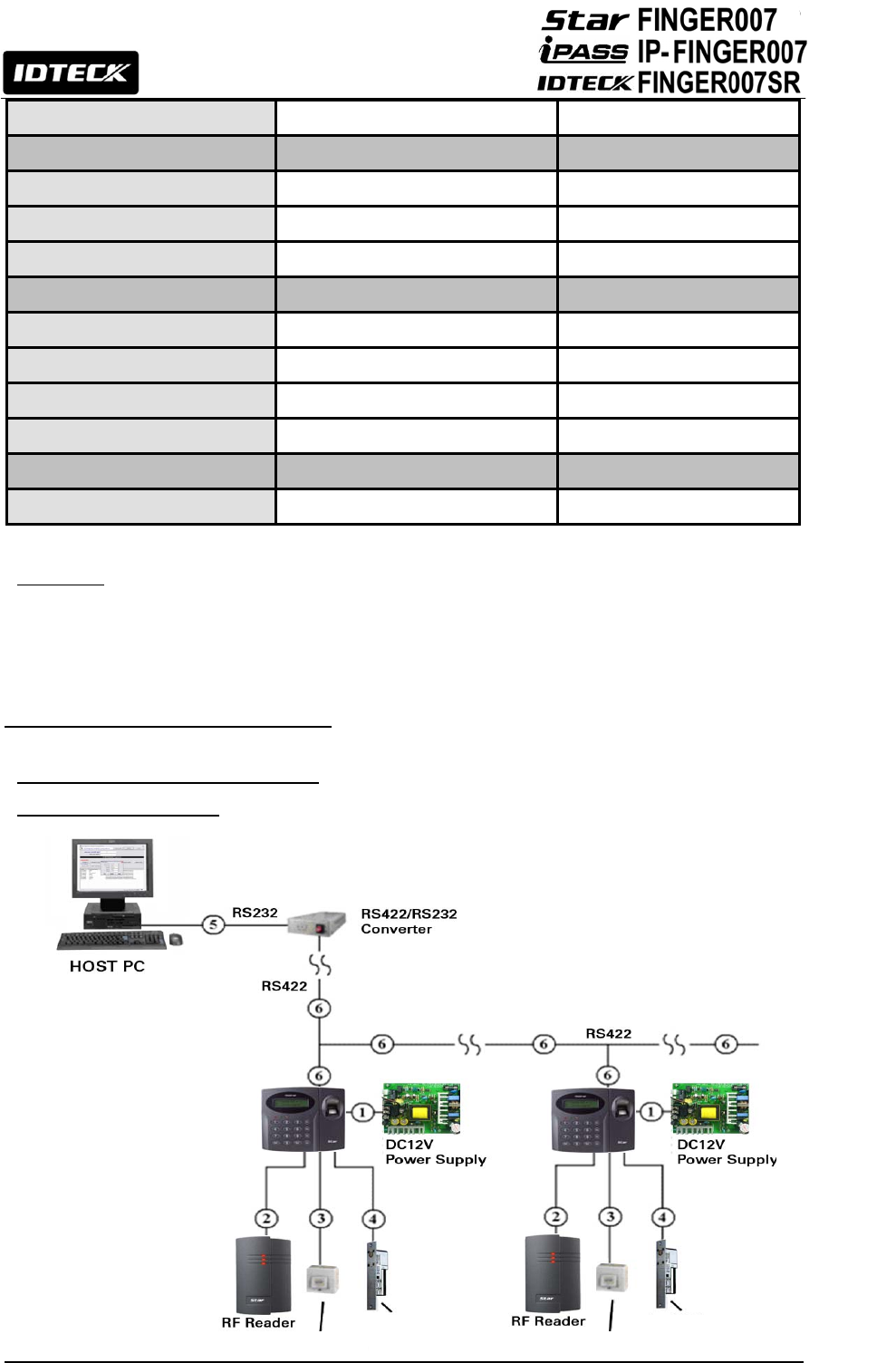
7.1.1 Installation Layout
Exit Button
Door Lock Exit Button
Door Lock

16
Figure: System Installation Layout
7.1.2 Recommended Cable Type
Reference
Description Cable Specification
① Finger007 Power (DC12V)
DC Power -> Finger007
Belden #9409, 18 AWG
2 conductor, unshielded
②* Reader (Power and Data)
External Reader -> Finger007
Belden #9512, 22 AWG
4 conductor, shielded
Belden #9514, 22 AWG
8 conductor, shielded
③
Door Contact
Exit Button
Sensor Input
Input -> Finger007
Belden #9512, 22 AWG
4 conductor, shielded
Belden #9514, 22 AWG
8 conductor, shielded
④ Door Lock, Alarm Device
Lock (Alarm) -> Finger007
Belden #9409, 18AWG
2 conductor, unshielded
⑤ RS232 Cable
Converter -> PC
Belden #9829, 24 AWG
2 twisted pair, shielded
⑥
RS485 Cable
Finger007 -> Finger007
Finger007 -> Converter
Belden #9829, 24 AWG
2 twisted pair, shielded
RS422 Cable
Finger007 -> Finger007
Finger007 -> Converter
Belden #9830, 24 AWG
3wisted pair, shielded
* Thicker wires are needed if you connect a reader with high current consumption.
7.2 Check Point during Installation
7.2.1 Termination Resistor
Termination Resistors are used to match impedance of the network to the impedance of the
transmission line being used. When impedance is mismatched, the transmitted signal is not
completely absorbed by the receiver and a portion of signal is reflected back into the transmission
line.
The decision whether or not to use Termination Resistors should be based on the cable length and
data rate used by the communication system.
For example, if you use 9,600 baud rate and 1,200m length of cable, the propagation velocity of
cable is 0.66 x speed of light (This value is specified by the cable manufacturer), if we assume the
17
reflections will damp out in three round trip up and down the cable length, the transmitted signal will
stabilize 18.6us after the leading edge of a Bit. Since the data Bit is captured in the middle of the Bit
which is approximately 52us after the leading edge of a Bit. The reflection stabilizing time 18.6us is
much before the center of the Bit therefore the Termination Resistors are not required.
However, if you install the cable to maximum length, the impedance of cable and network is
mismatched and the transmitted signal is overlapped by the reflected signal. In this case, it is
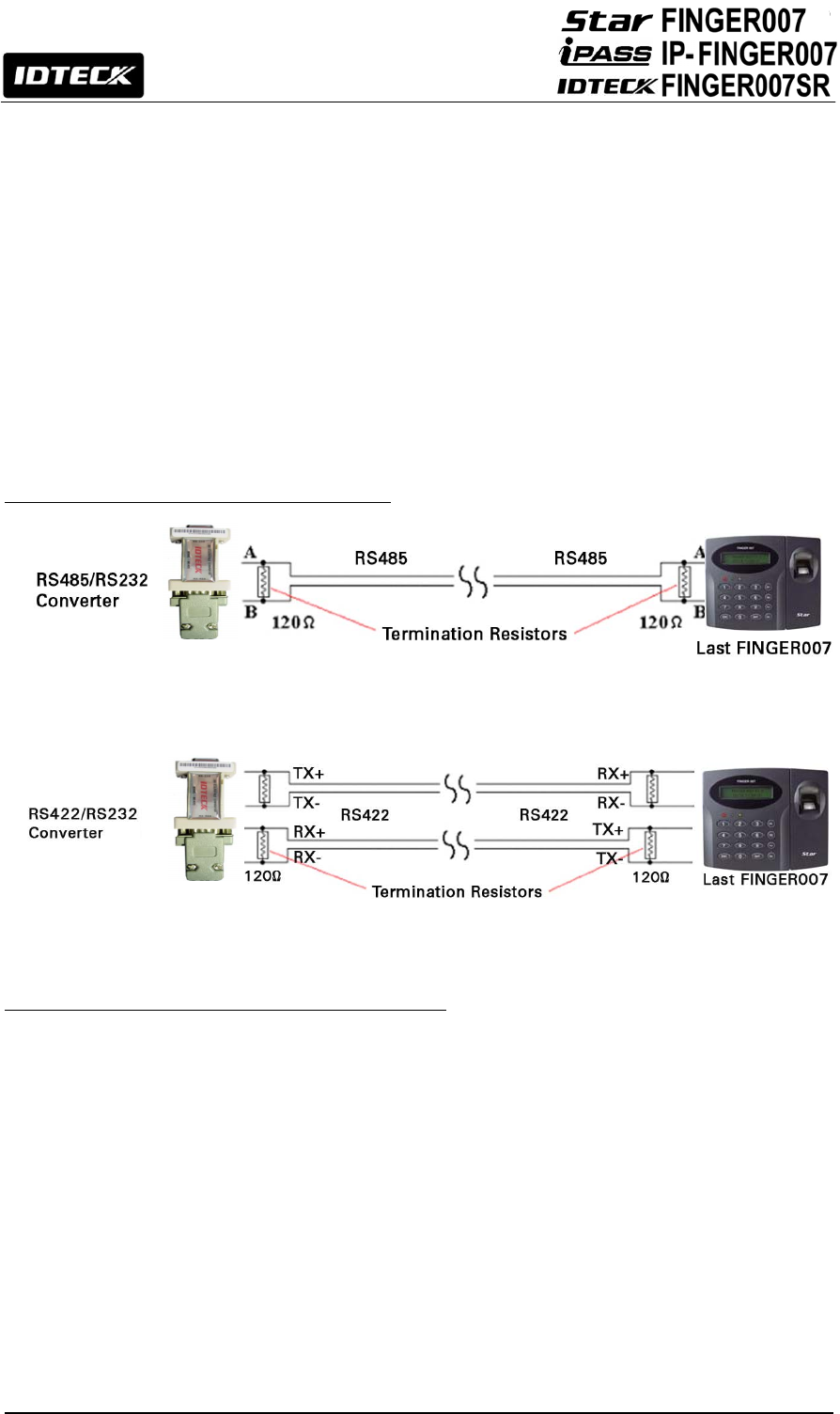
recommended to add Termination Resistors to the end of the receiver lines. A 120Ω resistor can be
used for Termination Resistor in parallel between the receiver lines “A” and “B” for 2 wires RS485
system or “RX+” and “RX-” for 4 wires RS422 system. A Termination Resistor of less than 90Ω
should not be used and no more than 2 terminations should be used in one networking system.
7.2.2 How to Connect Termination Resistors
Figure: Termination Resistors for 2 Wire RS485 Communication System
Figure: Termination Resistors for 4 Wire RS422 Communication System
7.2.3 Grounding System for Communication Cable
We recommend to using proper Grounding System on the communication cable. The best method
for Grounding System is to put the shield wire of the communication cable to the 1st class earth
grounding; however it is not so easy to bring the earth ground to the communication cable and also
the installation cost is raised.
There will be three grounding point where you can find during installation;
1) Earth Ground
2) Chassis Round
3) Power Ground
The most important point for Grounding System is not to connect both ends of shield wires to the
Grounding System; in this case there will be a current flow through the shield wire when the voltage
level of both ends of shield wire is not equal and this current flow will create noise and interfere to
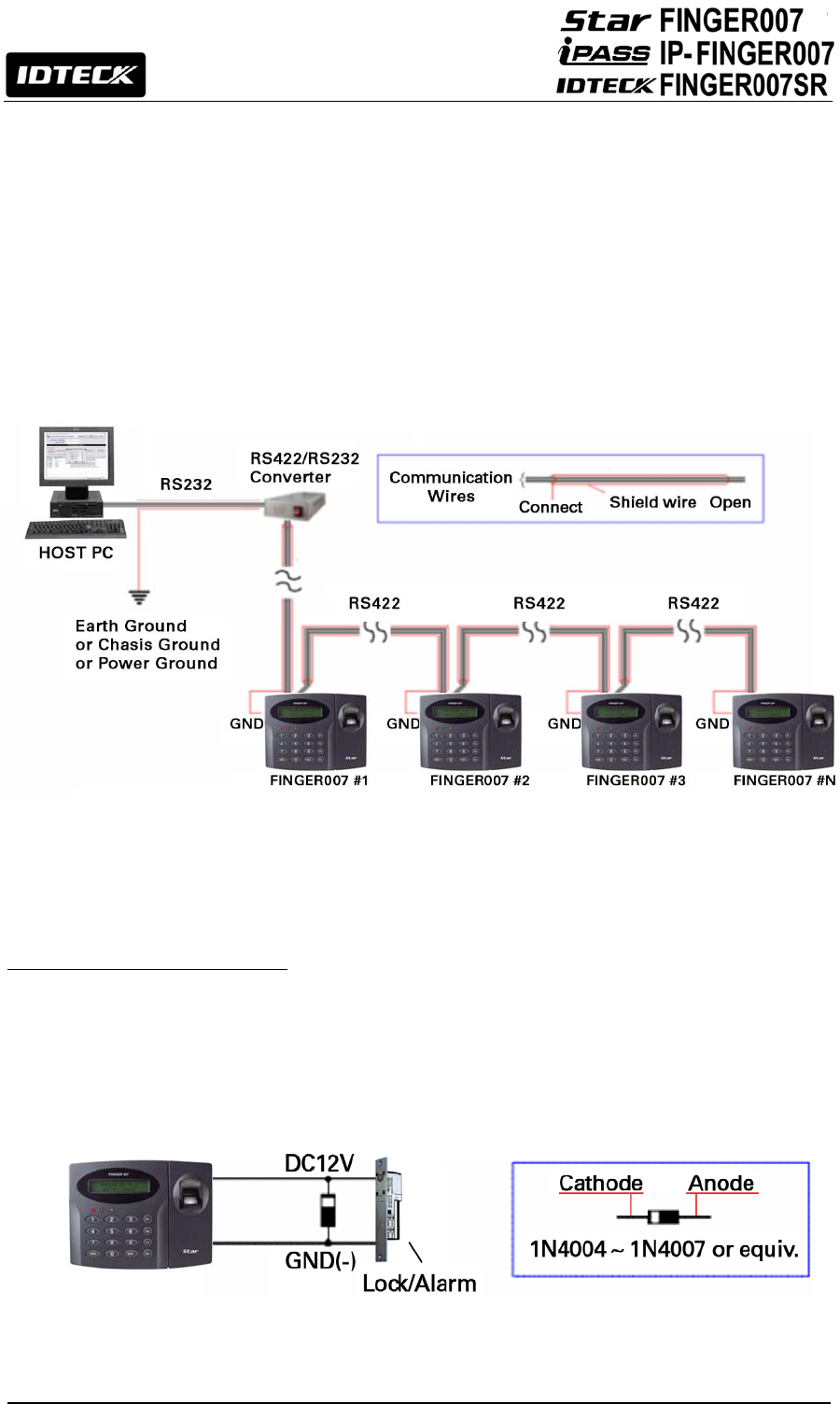
18
communications.
For the good grounding, we recommend to connecting only one end of shield wire of communication
cable to Grounding System; If you find earth ground nearby, then connect one end of shield wire to
earth ground; If you do not have earth ground nearby, then find chassis ground and connect one end
of shield wire to chassis ground; If you do not find both earth ground and chassis ground, then
connect one end of shield wire to power ground. (GND of FINGER007)
Note: if the chassis ground is not properly connected to the earth and floated from the ground level,
then grounding to the chassis ground will give the worst communication; in this case we recommend
using power ground instead of chassis ground.
Figure: Grounding System
7.2.4 Reverse Diode Connection
If you connect an inductor (Door Locks or Alarm Device) to the output relays, there will be a high
surge voltage created while the inductor is turning on and off. If you do not connect Reverse Diode,
the surge voltage will transfer and damage the electronic circuit of the controller. It is strongly
recommended to add a Reverse Diode between the inductor coils to absorb this surge voltage.
Figure: Reverse Diode Connection

19
8. Installation of the Product
8.1 Template
Real size template is on 65p in this manual. Tear off the template page and attach it to the wall. And
then follow steps below to install the Star FINGER007. (You can install the Star FINGER007 directly,
if the gang box is installed on the wall.)
1. Position the Wall Mount template to the location at which you want to install the unit and mark two
drilling (two Tap #6-32 holes) positions and then drill it
2. Drill a 1/2” hole on the center of the wall mount.
3. Using two screws, install the wall mount to the hall.
4. Take out the cable through the center hole.
5. After connecting cables, initialize the Star FINGER007. And then test basic function. (Refer to ‘8.2
SYSTEM INITIALIZATION’)
6. Insert O-ring at 5 positions and then insert the bundle of cable to the center hole.
7. Put the Star FINGER007 unit on the wall mount and push it until it is fixed up.
Figure: Template Sample
※
CAUTION
Before mounting the Star FINGER007 unit to the Wall Mount bracket, operational test of the unit
should be completed, as the locking pins will lock the unit to the Wall Mount. Removing the unit from
the Wall Mount bracket after they have been installed together may cause damages to the bracket
and render its effectiveness.
Insert 5 O-rings to the wall mount as indicated, then route the cable of the main unit through the
20
center hole and push the main unit to wall mount to lock the main unit and make sure that the main
unit is locked with wall mount.
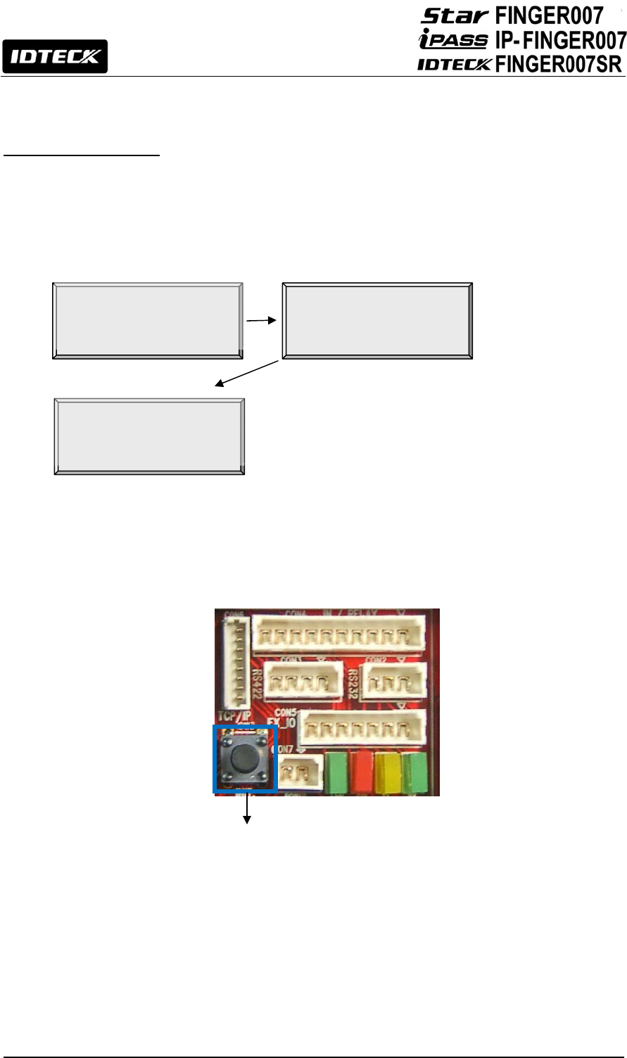
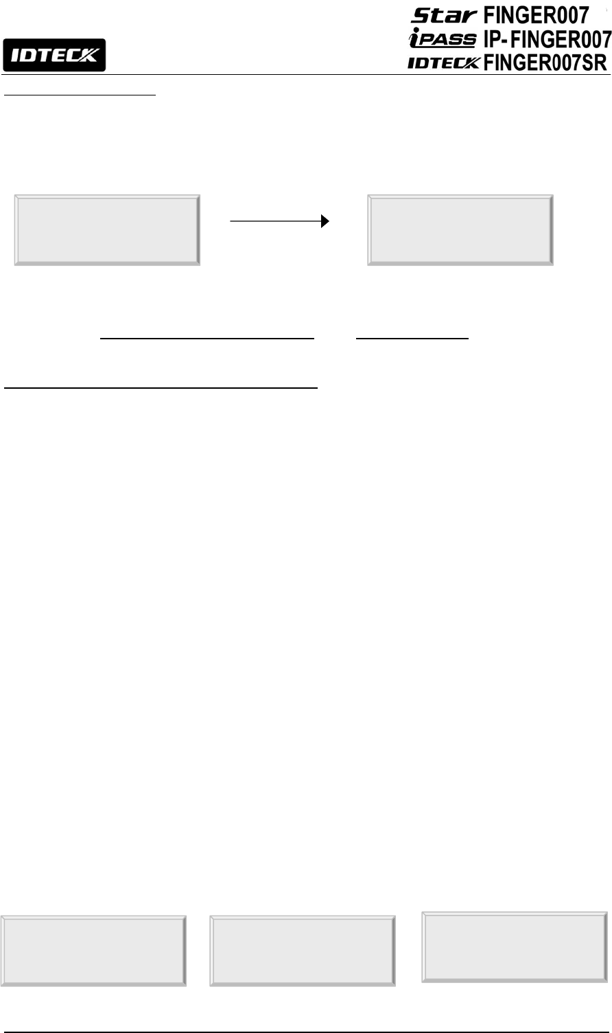
8.2 System Initialization
You have to initialize the FINGER007 unit prior to first installation.
Once power is supplied to the FINGER007, press down the initialization switch on the back of the
FINGER007 unit and then keep it more than 2 seconds, then you can see displays below on the LCD.
If you want initialization, press key <1> otherwise press key <0>.
○1 Press the key <1> if you wish to initialize the FINGER007.
○2 Initialization is progressing
○3 Rebooted automatically after Initialization
Figure: The Position of Initialization Switch
○
1
SYSTEM INIT.
1 – YES, 0 - NO
○
2
WAITING !!!
○
3
INIT. OK !!!
Initialization Switch
21
8.3 Wiring
8.3.1 Power
- Connect (+) wire of DC 12V power to +12V (Red wire)
- Connect GND (-) wire of DC 12V power to GND (Black wire)
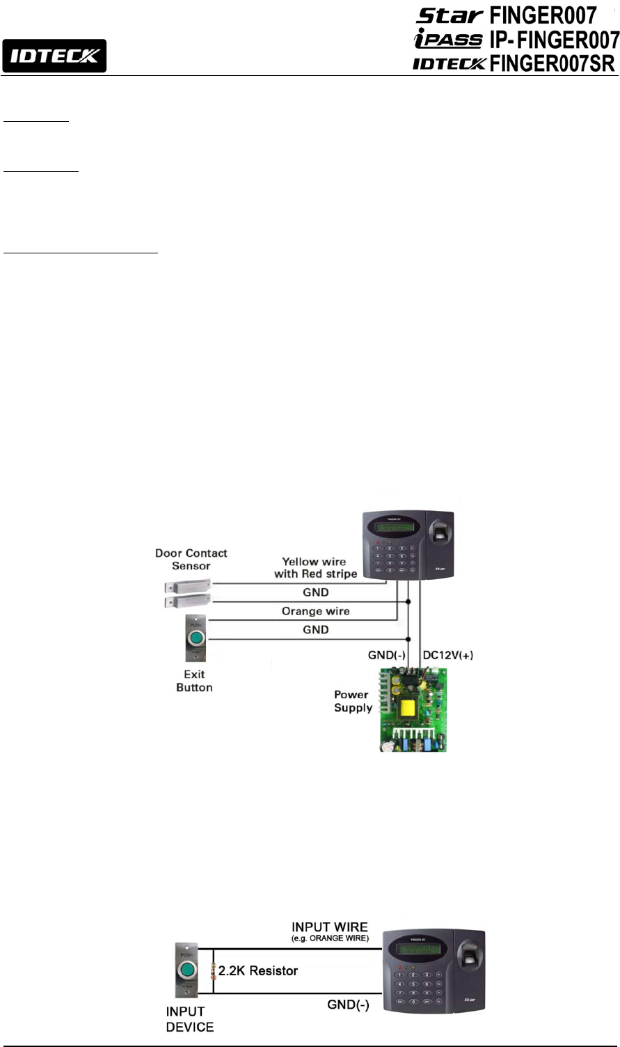
8.3.2 Input Connections
Exit Button Connection (Exit)
- Connect one wire from an Exit Button to exit (Orange wire).
- Connect the other wire from the Exit Button to the GND (Black wire).
Door Contact Sensor Connection (Contact)
- Connect one wire from a Door Contact Sensor to contact (Yellow wire with Red stripe).
- Connect the other wire (NC) from the Door Contact Sensor to GND (Black wire).
Auxiliary Input Connection (Applied IN1, IN2)
- Connect one wire from an Auxiliary Input device to one of the IN1 (Green wire), IN2 (Green with
White stripe).
- Connect the other wire from the Auxiliary Input device to GND (Black wire).
Figure: Input Devices Connection
2.2K Resistance Connection for Cut Off Check
You have to connect a 2.2K Resistor between the input wire (e.g. Orange wire) and the
GND to apply the Cut Off Check feature. First, select whether or not to check the Cut Off
status of each device from “F2 SETUP MENU” -> “CUT OFF CHECK”. Second, set the desired
output that will be generated in the event of a cut off from “F2 SETUP MENU” -> “CUT OFF
ALARM”.
22
Figure: 2.2K Resistance Connection for Cut Off Check
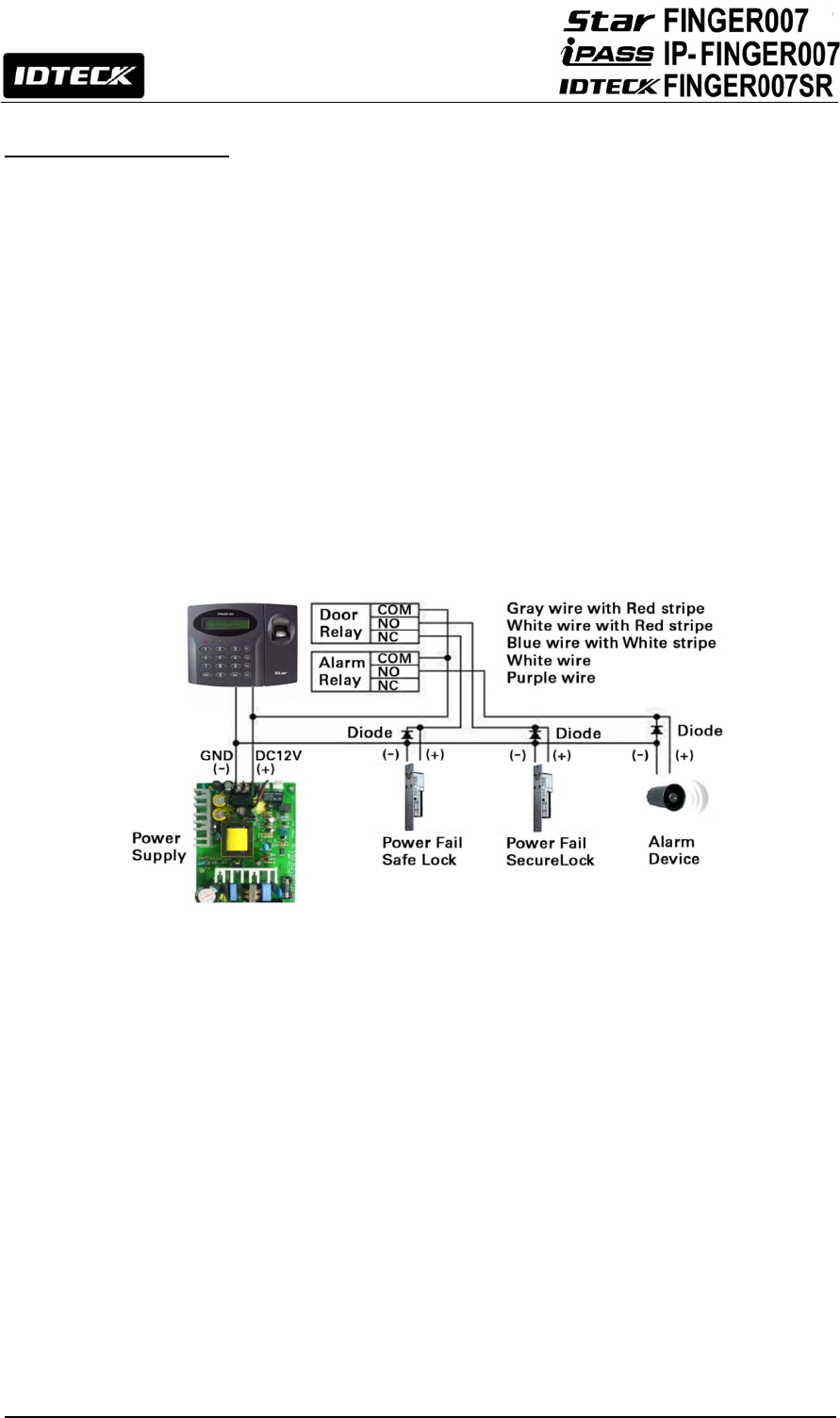
8.3.3 Output Connections
Door Lock (Power Fail Safe) Connection (Relay 1)
- Connect COM port of Relay 1(Gray with Red stripe) to + 12V (Red wire)
- Connect NC port of Relay 1(Blue with White stripe) to (+) wire of Door Lock Device.
- Connect GND (Black wire) port to (-) wire of Door Lock Devices.
Door Lock (Power Fail Secure) Connection (Relay 1)
- Connect COM port of Relay 1(Gray with Red stripe) to + 12V (Red wire)
- Connect NO port of Relay 1(White with Red stripe) to (+) wire of Door Lock Device
- Connect GND (Black wire) port to (-) wire of Door Lock Devices
Alarm Device Connection (Relay 2)
- Connect COM port of Relay 2 (White) to + 12V (Red wire)
- Connect NO port of Relay 2 (Purple) to (+) wire of Alarm Devices.
- Connect GND (Black wire) port to (-) wire of Alarm Devices
Figure: Door Lock / Alarm Device Connection
CAUTION: Please add one diode as shown above. A fast recovery diode (Current: Min. 1A), 1N4001
- 1N4007 or similar, is recommended.
Wiegand Data Connection (Applicable to Reader Mode)
-Connect DATA0 IN wire of controller to TTL1/D0 (TTL Output1) wire of FINGER007 (Orange with
White stripe)
- Connect DATA1 IN wire of controller to TTL2/D1 (TTL Output2) wire of FINGER007 (Brown with
White stripe)
CAUTION: If the controller and FINGER007 use separate power sources, you must connect the
GND between the controller and FINGER007.
23
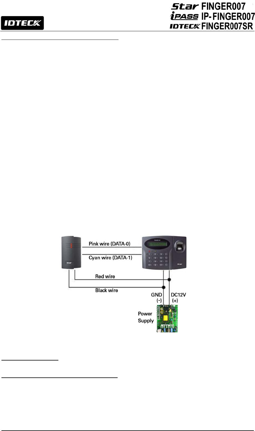
8.3.4 Reader Connections (External Reader)
• Proximity Reader Connection
- Connect (+) wire of FINGER007 to +12V (Red wire)
- Connect (-) wire of FINGER007 to GND (Black wire)
- Connect DATA0 wire of FINGER007 to DATA0 (Pink wire)
- Connect DATA1 wire of FINGER007 to DATA1 (Cyan wire)
CAUTION: If the controller and the external reader use separate power sources, you must connect
the GND between the controller and the external reader.
• Compatible Readers(External Reader)
FINGER007 / IP-FINGER007:
Standard 26BIT Wiegand Format Proximity Readers
Standard 26BIT Wiegand + 8BIT Burst Format Proximity and Keypad Reader
RF-TINY, RF10, RF20, RF30, RF70, RF500, RFK101
FGR006, FGR006EX, iP10, iP20, iP30, iPK101
FINGER007 Ver. A.0.0 or over (Wiegand Output Function).
FINGER007SR:
Standard 34BIT Wiegand Format Proximity Reader
Standard 34BIT Wiegand + 8BIT Burst Format Proximity and Keypad Reader
SR10, SR20, SR30, SRK101, FGR006SR, FGR006SRB
FINGER007SR Ver. A.0.0 or Over (Wiegand Output Function).
Figure: Reader Connection
9. Communication
9.1 RS232 Communication Port Connection
A 9-PIN connector (Serial Communication Connector, Female) is required to connect the FINGER007 to the
PC via RS232 communication.
Please follow the instructions.
- Connect RS232-TX (Black wire with White stripe) port of FINGER007 to the PIN 2 of the 9-PIN connector.
- Connect RS232-RX (Red wire with White stripe) port of FINGER007 to the PIN 3 of the 9-PIN connector.
24
- Connect RS232-GND of FINGER007 to the PIN 5 of the 9-PIN connector.
- Plug in the 9-PIN connector to COM1 or COM2 port of the PC.
- Install and run FINGER007 Application Software.
CAUTION: The firmware upgrade may not succeed if the distance between the PC and the device is
too far. A USB-to-serial converter is recommended if the PC has no COM ports.
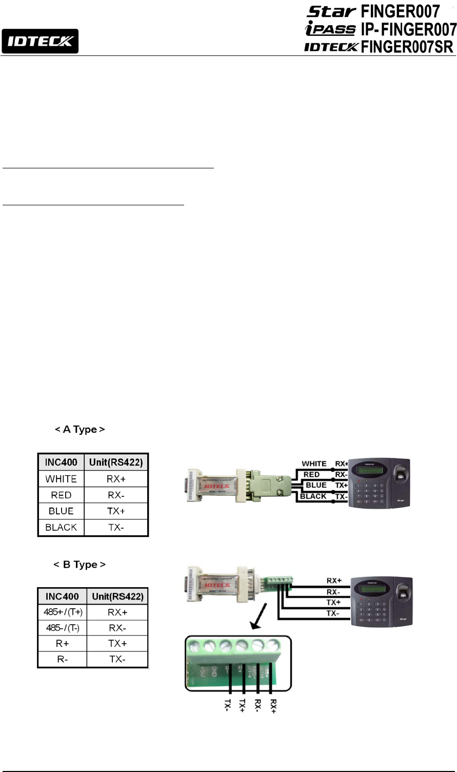
9.2 RS-422 Communication Port Connection
9.2.1 RS-422 Connection (Standalone)
An RS422/RS232 converter is required to use RS422 communication between the FINGER007 and
the PC.
CAUTION: An INC400 converter is recommended for stable communication when the distance between
the converter and the device is too far.
Please follow the instructions below;
- Connect RS422-TX (+) (Gray wire) of FINGER007 to RS422-RX (+) port of converter.
- Connect RS422-TX (-) (Yellow wire) of FINGER007 to RS422-RX (-) port of converter.
- Connect RS422-RX (+) (Brown wire) of FINGER007 to RS422-TX (+) port of converter.
- Connect RS422-RX (-) (Blue wire) of FINGER007 to RS422-TX (-) port of converter.
- Plug in the RS232 9PIN connector of the converter to the COM1 or COM2 port of the PC.
- Install and run FINGER007 Application Software.
Figure: RS422 Communication between FINGER007 and the PC
25
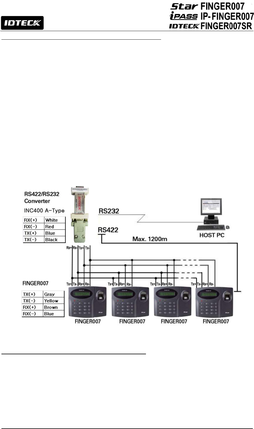
9.2.2 RS-422 Connection (Multiple FINGER007 Connections)
RS422/RS232 converter is required to use RS422 communication between multiple FINGER007s
and the PC. Please follow the following instructions.
First, you have to connect all RS422 port of all FINGER007s in parallel.
- Connect RS422-TX (+) of one FINGER007 to RS422-TX (+) of another FINGER007.
- Connect RS422-TX (-) of one FINGER007 to RS422-TX (-) of another FINGER007.
- Connect RS422-RX (+) of one FINGER007 to RS422-RX (+) of another FINGER007.
- Connect RS422-RX (-) of one FINGER007 to RS422-RX (-) of another FINGER007.
Second, you have to connect one of RS422 port of FINGER007 to RS422/RS232 converter.
- Connect RS422-TX (+) of the one FINGER007 to RX (+) port of the converter.
- Connect RS422-TX (-) of the one FINGER007 to RX (-) port of the converter.
- Connect RS422-RX (+) of the one FINGER007 to TX (+) port of the converter.
- Connect RS422-RX (-) of the one FINGER007 to TX (-) port of the converter.
- Plug in the RS232 9PIN connector of the converter to the COM1 or COM2 port of the PC.
- Install and run FINGER007 Application Software.
Figure: RS422 Communication between FINGER007s and PC
9.3 TCP/IP Communication Port Connection (Optional)
Optional TCP/IP module is required to use TCP/IP communication between the FINGER007 and the
PC. Please follow the following instructions.
1. Connect the LAN cable of the network system to the RJ45 jack of the FINGER007.
2. Set the ID of the FINGER007.
3. Install and run the FINGER007Application Software.
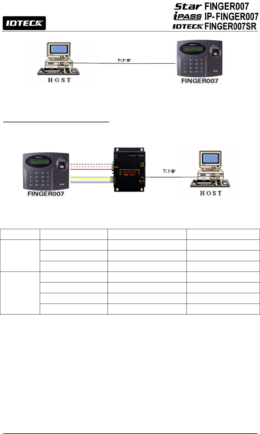
26
Figure: TCP/IP Connection with FINGER007 and Host PC
9.4 TCP/IP Converter (External Version)
When you use the TCP/IP converter, choose only one converter between RS232 and RS422.
Figure: TCP/IP Converter between FINGER007 and Host PC
INTERFACE FINGER007 ILAN422 LINE COLOR
RS232
TX (CON2) RX (RS232 DSUB9) Black with White Stripe
RX (CON2) TX (RS232 DSUB9) Red with White Stripe
GND(CON2) GND Black
RS422
TX+ (CON3) RX+ (RS422 CONNECTOR)
Gray
TX- (CON3) RX- (RS422 CONNECTOR)
Yellow
RX+ (CON3) TX+ (RS422 CONNECTOR)
Brown
RX- (CON3) TX- (RS422 CONNECTOR)
Blue
27
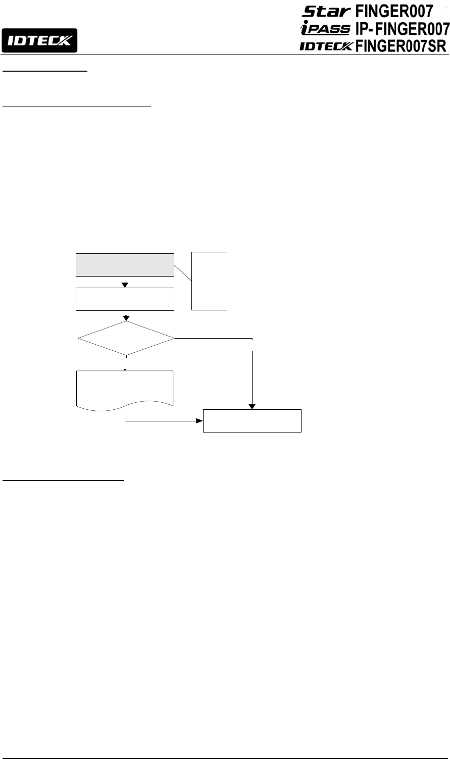
10. Initial Setup
10.1 Initialization of FINGER007
After completing installation and cable connections, apply power (DC12V) to the FINGER007. Press
down the initialization switch on the back of the FINGER007 unit and then keep it more than 2
seconds. Then, the LCD will first display “Initialize OK? 1: Yes 0: No”. Press <1> key if you want to
initialize the system or <0> to cancel the initialization procedure. After all the initialization process is
completed, the system will be operating in the normal mode and the LCD will display “FINGER007
[F1], MM/DD hh : mm : ss”.
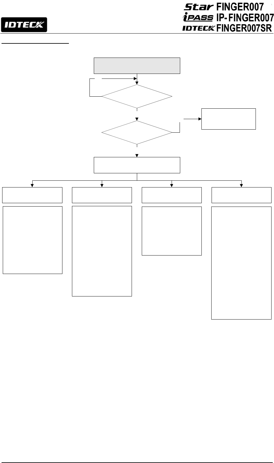
10.2 Entering Setup Mode
To setup or to change the FINGER007 settings, you have to enter the Setup Mode first. To do so,
enter the Master ID (default=00000000)* and press the <ENT> key. There are 4 main Setup menus
and you automatically get into “SETUP MENU F1” first. You can move to other Setup menus by
pressing the <F1> key for “SETUP MENU F1”, <F2> key for “SETUP MENU F2”, <F3> key for
“SETUP MENU F3” and <F4> key for “SETUP MENU F4”. There are setting items in the main Setup
Menu and you can scroll up or down the menu by pressing the <4> or <6> key. If you press the
<ESC> key then the FINGER007 will exit the Setup Mode and return to normal operation in Reader
Mode.
*The default Master ID for the FINGER007SR is 0000000000 (Press the <0> key 10 times)
<1> KEY?
“SYSTEM
IN IT IA L IZ E D !!!”
Power ON
In itia lize O K ?
1: Yes 0: No
Normal Operation
Yes
No
Press and hold the initialization button.
Apply +12V DC power to the FINGER007.
Release the button when the LCD displays
“In itia lize O K ?”
28
10.3 Time / Date Setting
After you enter the Setup Mode, you will see the following screen with the current date and time. To
adjust the time / date setting, press <ENT>, then enter 15 Digits in a YYYYMMDDhhmmssW format,
and then enter <ENT> again to confirm.
NOTE: For the day of the week (W), 1 : Sun, 2 : Mon, 3 : Tue, 4 : Wed, 5 : Thu, 6 : Fri, 7 : Sat.
e.g. To express August 24, 2009, 13:30:15, Monday, enter 200908241330152.
10.4 Setting Maximum Number of Cardholder IDs
You can set the maximum number of cardholder IDs that can be registered on your FINGER007. By
default, the FINGER007 is set to store up to 10,000 cardholders and 50,000 events and you can
adjust this setting to increase the cardholder capacity at the expense of event memory.
To change the ID memory setting, enter the Setup Mode (See 10.2 Entering setup mode), press
<F3>, then press <6> 4 times until you see 5.ID memory on the LCD. (See figure 1.) Once the 5.ID
memory item appears on the LCD, press <ENT>, and press <4> or <6> to select “10000/50000”,
“20000/40000”, “30000/30000”, “40000/20000” or “50000/10000” (No. of IDs / No. of events), and
then press <ENT> again to confirm.
NOTE : Prior to changing the maximum number of cardholders, you must clear the event data from
the memory. Because entering the Setup Mode itself generates an event, you must always initialize
the event memory prior to changing the maximum ID number setting. For additional information on
how to intialize the event memory.( refer to 12.1.9 Event clear). If you attempt to change the setting
with some event data still in the memory, the LCD will display “EVENT MEMORY NOT EMPTY” error
message. (See figure 2.)
NOTE: If you attempt to reduce the ID memory size to a value lower than the current number of IDs
stored in the memory, the LCD will display the “ID TOTAL COUNT WRONG” error message. (See
figure 3.) If this is the case, please clear the card data from the memory. For additional information
on how to initialize the card memory (See 12.1.8 Card ID clear.)
Figure 1. Figure 2. Figure 3.
1. TIME SETTING
MM/DD hh:mm:ss
YYYYMMDDhhmmssW
■
<ENT>
7. ID MEMORY
10000/50000
EVENT MEMORY
NOT EMPTY!
ID TOTAL COUNT
WRONG!!!

29
10.5 Registering Cardholder IDs
To add new cardholder IDs to the FINGER007, enter the Setup Mode (See 10.2 Entering Setup
Mode), press <F3>. Once the 1.ID registration item appears on the LCD, press <ENT> to begin the
ID registration process.
For detailed information on the ID registration process, please refer to 12.3.1 ID registration.
NOTE: How to place your finger onto the scanner when you register card ID:
When you register or verify your fingerprint, please place your finger onto the scanner correctly as
illustrated below.
Figure: How to Put Your Finger on the Scanner
11. Operation
11.1 Normal Operation
Power On
When the power is applied to FINGER007, the “RED LED” is turned on.
Fingerprint Identification
1. If registered card is read by the unit, red LED of fingerprint sensor is on.
At this time, you should put your finger and then remove your finger if red LED is off.
2. If fingerprint identification is done, card ID or authorization status appears on the
LCD and fingerprint quality level also appears.
e.g.) [Q3]
3. Quality level appears from 1 to 5.
In case of Q1 or Q2, you can’t use on Identification Mode (1: N) because of bad quality.
In case of Q3, Q4 or Q5, you can use on Identification Mode (1: N) because of good quality.
e.g.) In case of fingerprint identification
–
Quality Level: 3, Card ID: 12300111

30
Registered Card Reading
When a registered card (or PIN) is read, the door (Relay1) will open for 3 seconds
(Defaults) with the “GREEN LED” on.
Exit Button
To request for exit from the inside, an Exit Button (Or External Reader) can be used.
The Door (Relay1) will open for 3 seconds (Defaults) with the on.
Alarms (Unregistered / Password / Fingerprint / Time Schedule / Door error)
When an unregistered card is read, wrong password is input, wrong fingerprint is input, over the
Time Schedule, and access wrong door, the access is denied and the alarm (Relay 2) will be
activated for 3 seconds (Defaults) with “RED LED” on.
11.2 Default Setting
When you operate the FINGER007 first time or you initialize the FINGER007, the controller
will setup all values defaults (Factory Settings). You can change the settings for desired
application. Please refer to the “APPENDIX” section at the back of this manual for the default
setting values.
31
12. Setting Changes
INITIAL DISPLAY
(MODEL NAME, CURRENT TIME)
ID INPUT?
MASTER ID
/PW/FINGERPRINT ?
YES
YES
NO OPERATE IN
READER MODE
SETUP MODE
NO
SETUP MODE F1 SETUP MODE F2 SETUP MODE F3 SETUP MODE F4
1. TIME SCHEDULE
2. HOLIDAY T/S
3. HOLIDAY CODE
4. READER T/S
5. IN/OUT DEFINE
6. OUTPUT TIME
7. APB SETUP
8. RF PIN INPUT
9. EVENT MEMORY
10. DURESS MODE
11. DOOR ALARM
12. LCD DISPLAY
13. BUZZER STATUS
14. DATA BYTE
1. F/W VERSION
2. MEMORY TEST
3. OUTPUT TEST
4. LCD TEST
5. KEYPAD TEST
6. READER TEST
7. INPUT TEST
8. COMM TEST
9.IDENTIFICATION
10.DUAL FINGER
11.ADAPTIVE
12. FP STATUS
13.HIGH SECURITY
14.FP QUALITY
15.FP LEVEL
16.FP VERSION
17.FP COUNT
18.FP TEST
19.DEVICE IFO
1. TIME SETTTING
2. COMM ADDRESS
3. BAUD RATE
4. READER 1 MODE
5. READER 2 MODE
6. MASTER ID
7. SYSTEM CLEAR
8. CARD ID CLEAR
9. EVENT CLEAR
10. T/S CLEAR
1. REGISTRATION
2. ID DELETE
3. ID LIST
4. REG. ID COUNT
5. ID MEMORY
6. EVENT LIST
7. EVENT COUNT
To setup or to change the FINGER007 settings, you have to enter the setup mode first. To do so,
enter the Master ID (Default=00000000)* and press the <ENT> key. There are 4 main Setup menus
and you automatically get into “SETUP MENU F1” first. You can move to other setup menus by
pressing the <F1> key for “SETUP MENU F1”, <F2> key for “SETUP MENU F2”, <F3> key for
“SETUP MENU F3” and <F4> key for “SETUP MENU F4”. There are setting items in the main setup
menu and you can scroll up or down the menu by pressing the <4> or <6> key. If you press the
<ESC> key then the FINGER007 will exit the Setup Mode and return to normal operation in Reader
Mode.
*The default Master ID for the FINGER007SR is 0000000000 (Press the <0> key 10 times)
32
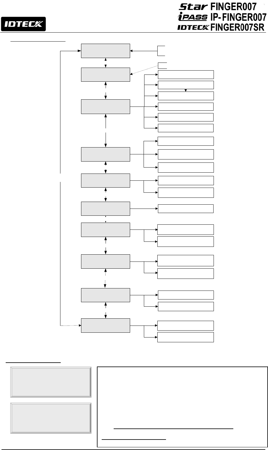
12.1 Setup Menu F1
TIME SETTING
COMM ADDRESS
Scroll Key <4> or <6>
Scroll Key <4> or <6>
Scroll Key <4> or <6>
Scroll Key <4> or <6>
Scroll Key
<4> or <6>
BAUD RATE
19200
38400
57600
115200
EVENT CLEAR YES
NO
ENTER 15 DIGITS
(YYYYMMDDhhmmssW)
ENTER 2 DIGITS (00 - 31)
MASTER ID ENTER MASTER ID
READER 2 MODE
RF+P/W
RF ONLY (DEFAULT)
Scroll Key <4> or <6>
READER 1 MODE RF+P/W
RF ONLY
Scroll Key <4> or <6>
T/S CLEAR YES
NO
Scroll Key <4> or <6>
SYSTEM CLEAR YES
NO
CARD ID CLEAR YES
NO
Scroll Key <4> or <6>
Scroll Key <4> or <6>
RF + P/W + PF
9600(recommended)
4800
12.1.1. Time Setting
The LCD displays the current time. To change the time, press
<ENT>, enter 15 Digits in a “YYYYMMDDhmmssW” format,
and then enter <ENT> again to confirm.
NOTE: For the days of the week (W),
1 : Sun, 2 : Mon, 3 : Tue, 4 : Wed, 5 : Thu, 6 : Fri, 7 : Sat.
e.g. To input August 24, 2009, 13:30:15, Monday,
enter 200908241330152.
1. TIME SETTING
MM/DD hh:mm:ss
YYYYMMDDhhmmssW

33
12.1.2. Communication Address
12.1.3. Baud Rate
A communication address is a unique number assigned to
each device for communication. The default address is 00.
For proper communication with the PC, it is important that the
value you set here should match the value you set on the
application software. It is also important to make sure each
device on a loop has a unique address.
To change the communication address of the FINGER007,
press <ENT>, enter the desired 2-Digit address in the 00-31
range, and then press <ENT> again to confirm.
2. COMM ADDRESS
00
2. COMM ADDRESS
12■
Baud Rate is the measure of speed in serial communication.
As for the communication address, the baud rate you set here
should match the value you set on the software.
Baud Rates of 4800bps, 9600bps, 19200bps, 38400bps,
57600bps and 115200bps are supported, and 9600bps is
recommended.
To change the Baud Rate, press <ENT>, select the desired
baud rate by pressing <4> or <6>, and then press <ENT>
again to confirm.
NOTE: If a TCP/IP module is being used, the Baud Rate
setting must be the same as the TCP/IP module setting.
3. BAUD RATE
9600
3. BAUD RATE
->9600
Troubleshooting Communication Problems
Step 1. Match the communication address between the device and the Application Software.
Step 2. Match the Baud Rate between the device and the Application Software.
Step 3. Ensure that the COM port setting in the Application Software is correct.
Step 4. Ensure that the communication settings in the Application Software are as follows;
1) Parity Bit: None 2) Data Bit: 8 Bits 3) Stop Bit: 1 Bit

34
12.1.4. Reader1 Mode
12.1.5. Reader 2 Mode
4. READER 1 MODE
RF + FP(PW)
4. READER 1 MODE
->RF + PW + FP
Access Modes for Reader 1
1. RF ONLY: Users can access the door by presenting their card or entering their ID number.
2. RF+F/P (P/W): Users can access the door by presenting their card or entering their ID
number and then verifying their identity by a fingerprint. For users who did not register their
fingerprints, password verification is used instead of fingerprint verification.
3. RF+P/W+F/P: Users can access the door by presenting their card or entering their ID
number and then verifying their identity by both a fingerprint and a password.
You can decide which combination of RF card, fingerprint and
password verification you wish to use on Reader1 (the
FINGER007 device itself).
To change the Access Mode for Reader 1, press <ENT>, select
the “DESIRED MODE” by pressing <4> or <6>, and then press
<ENT> again to confirm.
5. READER 2 MODE
RF ONLY
5. READER 2 MODE
->RF + PW
Access Modes for Reader2
1. RF ONLY: Select this option if Reader 2 is operating without password verification
2. RF+ P/W: Select this option if Reader 2 uses password verification.
NOTE: Proper selection of this setting depends solely on whether Reader 2 uses password
verification, but it has nothing to do with whether Reader 2 uses fingerprint verification or not.
If you have an external reader connected to the FINGER007
(referred to herein as Reader 2), you must adjust this setting
according to what access mode is used on Reader 2.
To change the Access Mode for Reader 2, press <ENT>,
select the desired mode by pressing <4> or <6>, and then
press <ENT> again to confirm.

35
12.1.6. Master ID Registration
12.1.7. System Initialization
6. MASTER ID
ENTER ID NO.
-> 12345678■
Master ID is the number/card that you use to enter the Setup
Mode. For security reasons, it is advisable that you change
the default Master ID immediately and keep the new Master
ID / card confidential.
CAUTION: Beware that if you forget the Master ID, you
cannot access the Setup Mode.
To change the Master ID, press <ENT>, and then either enter
the desired 8Digit Master ID or present a card to the reader.
NOTE: For the FINGER007SR, the Master ID is 10Digits long
in the range of 0000000000 to 4294967295.
On the next screen, enter the desired 4Digit Master Password
in the PW field and, in the FP field, enter <0> if you wish to
access Setup Mode without master fingerprint verification or
<1> if you wish to use master fingerprint, in which case you
will be asked to place your fingerprint on the scanner twice in
the next step. When the Master ID/card registration is
successfully completed, the LCD displays the “REGISTRATION
OK” message.
ID: 12345678
PW: FP:
TO REGISTER F/P
PUT YOUR FINGER!
REGISTRATION OK!
NOTE: The default Master ID for FINGER007/P and IP-FINGER007 is 00000000 (Eight zeros),
but for the FINGER0007SR, it is 0000000000 (Ten zeros)
System initialization allows you to initialize the FINGER007.
Initialization clears all the user-defined data stored in the
device such as card data, input/output setting, Time
Schedules, etc.
CAUTION: Prior to system initialization, make sure to check
whether or not the data stored in the device is not needed,
since it will be deleted after the initialization.
To initialize the FINGER007, press <ENT>, and then press
<1> to confirm. If you wish to cancel and exit without
initialization, press <0> instead.
7. SYSTEM INIT.
7. SYSTEM INIT.
1 – YES, 0 - NO
WAITING ! !

36
12.1.8. Card ID Clear
12.1.9. Event Clear
12.1.10. Time Schedule Clear
Card ID clear allows you to delete all the card data from the
FINGER007.
CAUTION: Before you clear the card memory, make sure you
do not need the data stored in the device.
To clear the card data stored in the memory, press <ENT>,
and then press <1> to confirm. If you wish to cancel and exit,
press <0> instead.
8. CARD ID CLEAR
8. CARD ID CLEAR
1 – YES, 0 - NO
Event clear allows you to delete all the event data from the
FINGER007.
CAUTION: Before you clear the event memory, make sure
you do not need the data stored in the device.
To clear the event data stored in the memory, press <ENT>,
and then press <1> to confirm. If you wish to cancel and exit,
press <0> instead.
9. EVENT CLEAR
9. EVENT CLEAR
1 – YES, 0 - NO
T/S Clear allows you to delete all the data related to time
scheduling, such as Time Schedules, Holiday and Reader
Time Schedules, Holiday Codes, etc.
CAUTION: Before you clear the time schedule Memory, make
sure you do not need the data stored in the device.
To clear the time schedule data stored in the memory, press
<ENT>, and then press <1> to confirm. If you wish to cancel
and exit,
p
ress <0>
instead.
10. T/S CLEAR
10. T/S CLEAR
1 – YES, 0 - NO
37
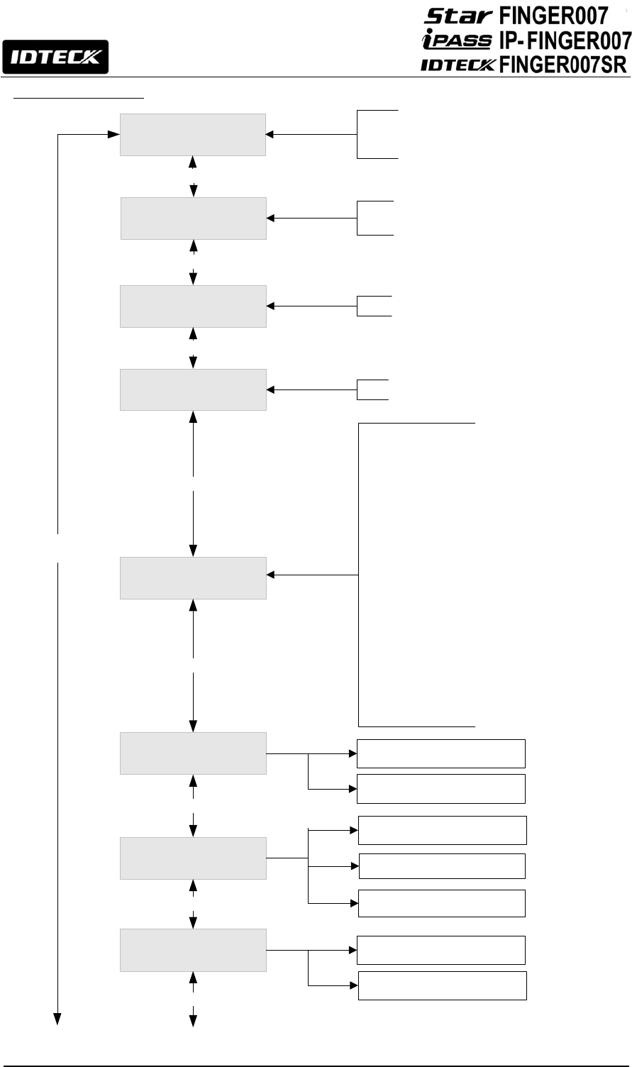
12.2 Setup Menu F2
TIME SCHEDULE
HOLIDAY DEFINE
IN/OUT DEFINE
Scroll Key <4> or <6>
Scroll Key <4> or <6>
Scroll Key <4> or <6>
Scroll Key
<4> or <6>
01: EXIT
02: DOOR CONTACT
03: INPUT # 1
04: INPUT # 2
05: TAMPER S/W
06: R1 ID OK
07: R1 ID ERROR
08: R1 T/S ERROR
09: R1 APB ERROR
10: R2 ID OK
11: R2 ID ERROR
12: R2 T/S ERROR
13: R2 APB ERROR
14: DURESS MODE
15: OUTPUT T/S
16: IN/OUT T/S
17: DR OPEN ALARM
18: CUT OFF ALARM
19: INPUT EVENT
20: EMERGENCY IN
21: CUT OFF CHECK
INDEX: 01 - 10
NO: 01 - 32
INDEX : 01 - 10
DAY OF WEEK: HOL, SUN, MON, ... SAT
NO: 01 - 05
HOLIDAY COED
READER T/S
Scroll Key <4> or <6>
HOLIDAY INDEX: 01 - 10
Scroll Key <4> or <6>
RF_PIN_INPUT DISABLE (DEFAULT)
ENABLE
Scroll Key <4> or <6>
APB SETUP ENABLE
Scroll Key <4> or <6> ALL CLEAR
OUTPUT TIME 1SEC(DEFAULT)
0.1SEC
Scroll Key <4> or <6>
DISABLE (DEFAULT)
TIME SCHEDULE INDEX: 01 - 10
38
12.2.1 Time Schedule
TIME SCHEDULE CURRENT TIME SCHEDULES ARE DISPLAYED
SELECT T/S NO AND INDEX
(USE <2> <8> <4> AND <6> KEYS)
ENTER 8-DIGIT T/S
(START TIME (hh:mm) - END TIME(hh:mm))
<ENT>
<ENT>
FINISHED?
YES
(PRESS <ESC>)
NO
39
12.2.2 Holiday Time Schedule
You can define up to 10 time schedule codes. Time schedule code
00 is the default code and can be used to allow round-the-clock
access. You can define time schedule codes 01 to 10. Each time
schedule code has 8 programmable days (i.e. Sun, Mon, Tue,
Wed, Thu, Fri, Sat and holiday) and each day has 5 time intervals.
1. TIME SCHEDULE
T / S: 01 HOL 1
hh : mm – hh : mm
How to Define Time Schedule Codes
To define a new T/S code or change an existing one, press <ENT>, and the LCD will show T/S
information such as T/S code, day, ti7me interval and time period. Press <2> or <8> to scroll up
or down the time schedule code (01-10) and the day of the week. (Mon - Sun and holiday).
Press <4> or <6> to scroll up or down the time interval. The holiday in this time schedule will be
linked to the holiday schedule code. Select a time schedule code, day and Interval, and press
<ENT>. Enter the start and end time for the time interval in the 24-hour, hh/mm format, then
press <ENT> to save the new T/S settings. Once all information is entered, press <ESC> to
return to the menu.
NOTE: You can also define time schedule codes using the Application Software. For more
information, please refer to the Software Manual.
You can define up to 10 Holiday T/S codes. Holiday T/S code
00 is the default code without any holidays. (This means that
applying Holiday T/S code 00 is the same as applying no
holidays at all.) You can define Holiday T/S codes 01 to 10.
Each holiday schedule code can have up to 32 holidays
defined.
2. HOLIDAY T/S
HOL TS : 01 #1
MM/DD

40
12.2.3 Holiday Code
12.2.4 Reader Time Schedule
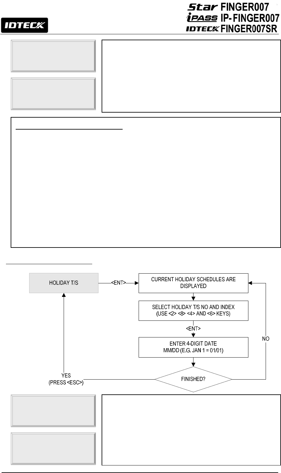
How to Define Holiday T/S Codes
To define a new Holiday T/S code or change an existing one, press <ENT>, and the LCD will
show holiday T/S information such as Holiday T/S code, holiday number and date. Press <2>
or <8> to scroll up or down the Holiday T/S code (01-10). Press <4> or <6> to scroll up or down
the time interval. Select a Holiday T/S code and index, and press <ENT>. Enter the date in the
MM / DD format, then press <ENT> to save the new holiday definition. Once all information is
entered, press <ESC> to return to the menu.
NOTE: You can also define time schedule codes using the Application Software. For more
information
,
p
lease refer to the Software Manual.
The Holiday code setting lets you link a holiday schedule to a
time schedule. The default holiday schedule code is 00, which
means no holidays are applied to the time schedule.
Use <4> or <6> to scroll up or down from the T/S code 01 to
10, and press <ENT>. Then, enter a 2Digit holiday schedule
code and press <ENT> to store the changed settings to the
memory. To return to the previous menu, press <ESC>.
3. HOLIDAY CODE
T/S INDEX 01
HOLIDAY CODE 00
You can select one of 3 Access Modes (i.e. RF Only Mode,
ID+F/P (PW) Mode and RF+PW+F/P Mode) in “READER1
MODE” of “F1 SETUP MENU”. However, you may apply RF
Only Mode during a certain period of the day. For example, if
you wish to allow RF-Only Access from 09:00 to 17:00 while
using fingerprint verification for the rest of the time, you can
proceed as follows;
1) Set “READER 1 MODE” to RF+F/P Mode.
(See 11.1.4. Reader 1 Mode)
2) Define T/S code 01 so that it can include a Time Interval
between 09:00 and 17:00 for the desired days of the
week. (See 11.2.1 Time Schedule)
3) Here in Reader T/S, press <ENT>, enter the 2Digit T/S
code (In this case, 01), and then press <ENT> again to
confirm.
4) To return to the previous menu, press <ESC>.
※Once you input READER T/S, internal and external
readers are set to the same value.
4. READER T/S
00
4. READER T/S
01■
41
12.2.5 Input / Output Definition
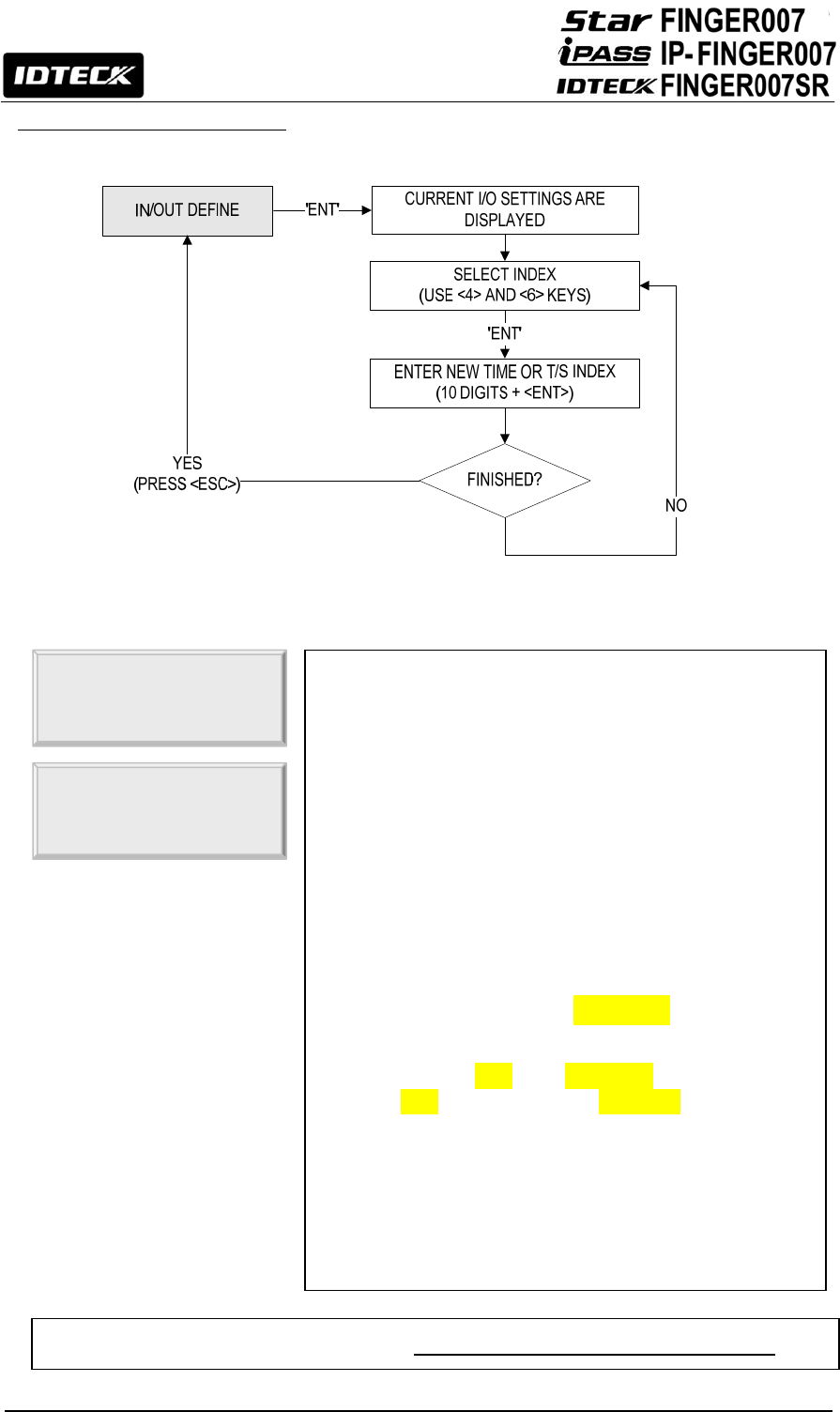
In/Output Define allows you to adjust In/Output settings
(Output activation time, In/Output Time Schedule, Cut-Off
Check, etc.).
To change the In/Output Settings, press <ENT> and select
an item using <4> or <6> key, and press <ENT> again. After
the cursor appears, enter the 10Digit number for the desired
setting. Once all information is entered, press <ESC> to
exit.
The range of values you can enter in each field is as
follows;
z 1-14, 17-18: 00 – 99 (99 is infinite)
z 15-16: 00-10 (Time Schedule Code)
z 19-21:” “USE” or ”NOT USE”(Selecting “01” is
“USE”, Selecting “00” is “NOT USE”)
NOTE: The 14.Duress Modem Setting allows you to decide
the output signal time for when access is granted following
a duress event.
NOTE: When a particular event occurs, the FINGER007 will
generate an output signal for Relays #1 and #2, TTL #1 and
#2, and Buzzer for the length of time defined for each.
5. IN/OUT DEFINE
EXIT
03 00 00 00 00
NOTE: For more information, please refer to 13.2 Default Settings for In/Output Relations.

42
12.2.6 Output Time Setting
12.2.7 Anti-Pass Back
6.OUTPUT TIME SET
1 Sec
6.OUTPUT TIME SET
- > 0.1 Sec
Output Time Setting Examples
e.g. If you want to activate the Door Relay (Relay #1, DR) for 3 seconds;
- The Time Unit should be set to 1 SEC.
- The Door Relay (DR) Output Time should be set to “03”.
e.g. If you want to activate Door Relay (Relay #1, DR) for 0.5 seconds;
- The Time Unit should be set to 0.1 SEC.
- The Door Rela
y
(
DR
)
Out
p
ut Time should be set to “05”.
Output Time Set allows you to define the unit of time.
z 1 sec: Output Time is calculated in the time unit of 1
second for the In/Output definition.
z 0.1 sec: Output Time is calculated in the time unit of 1/10
second (or 100ms) for the In/Output definition
To change the setting, press <ENT> and press <4> or <6> to
select the desired time unit and press <ENT> to confirm.
CAUTION: If your FINGER007 is set to Reader Mode and it
is “NOT” used in Standalone Mode, you must always set
“OUTPUT TIME” to 1 sec.
7. APB SETUP
NOT USE
7. APB SETUP
- > USE
Anti-Pass Back Setting Menu Items
z NOT USE: The Anti-Pass Back feature is disabled.
z USE: The Anti-Pass Back feature is enabled.
z ALL CLEAR!: All Anti-Pass Back flags are reset, and access will be allowed one time
regardless of the current status of the existing flags.
The Anti-Pass Back feature is used to prevent an identical
user from entering or exiting the door more than twice in a
row so that employees cannot pass back their cards to their
coworkers. Anti-Pass Back can be applied only when an Exit
Reader is installed. “DO NOT” enable it if an “Exit Button” is
installed instead of an Exit Reader.
For enable or disable Anti-Pass Back or resetting all APB
flags, press <ENT> and press <4> or <6> to select the
desired item and
p
ress <ENT>
to confirm.
43
12.2.8 RF PIN Input
12.2.9 Event Alarm
CAUTION: If the event memory becomes full, the oldest event data is overwritten and lost.
12.2.10 Duress Mode
8. RF PIN INPUT
NOT USE
8. RF PIN INPUT
- > USE
RF Pin Input allows you to decide whether to enable or
disable PIN (or RF card number) Input via the keypad. By
default, PIN Input is disabled.
Caution: If you choose “NOT USE”, you cannot gain access
via password input when using RF+PW mode. This is same
for external readers.
9.EVENT ALARM
USE
9.EVENT ALARM
- > NOT USE
Event Alarm allows you to decide whether to enable or
disable the event memory full alarm. If you enable Event
Alarm, the FINGER007 beeps with an alarm message when
the event memory becomes more than 90% full.
You can set it regardless of saved events.
To enable or disable Event Alarm, press <ENT> and press
<4> or <6> to select “USE” or “NOT USE”, and then press
<ENT> again to confirm.

44
12.2.11 Door Open Alarm Time
10. DURESS MODE
NOT USE
10. DURESS MODE
- > USE
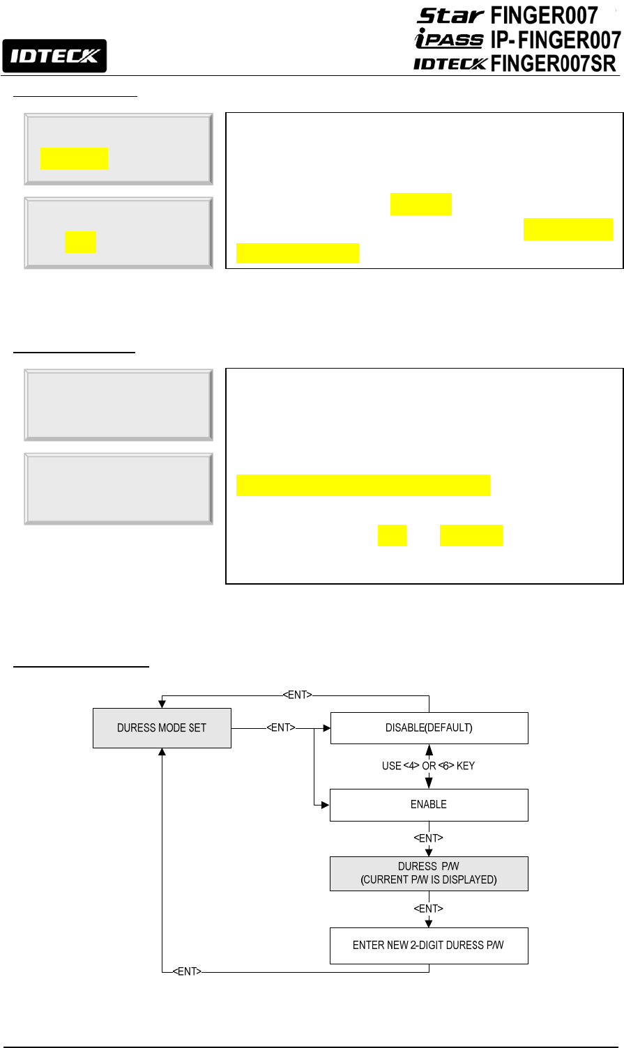
Duress Mode enables a cardholder under duress to activate a
silent alarm to notify the security.
To enable or disable the Duress Mode and / or set the Duress
Password, press <ENT> and press <4> or <6> to select
either “NOT USE” or “USE” If you select “USE” the LCD will
display the current “DURESS PASSWORD”. To change the
password, press <ENT> and enter the desired 2-Digit Duress
Password, and press <ENT> again to confirm. If you do not
wish to change the password, press <ESC>.
DURESS P/W
12■
NOTE: In case of duress, enter the 2Digit Duress Password and press <ENT> prior to the
regular access process. Following a successful access process, access will be granted as
usual but, at the same time, a duress alarm will be generated.
NOTE: To learn about how to change the duress alarm output settings, please refer to 11.2.5
In/Output Definition.
11. DOOR ALARM
03
11. DOOR ALARM
99■
Door Open Alarm Time refers to the delay between the time at
which the Door Relay time finishes and the time at which a
Door Open Alarm is activated. To change the Door Open Alarm
Time, press <ENT> and enter a 2Digit number as follows;
z 00: The alarm will be activated immediately if the door is
still left open past the Door Relay Time.
z 01-98: Delay (01-98 sec) will be inserted before an alarm
is activated.
z 99: No alarm.
After entering the number, press <ENT> to confirm.
NOTE: For this application, a Door Contact Sensor must be
installed on the door.
45
12.2.12 LCD Display
12.2.13 Buzzer Status
12.2.14 TTL WEIGAND Output
12. LCD DISPLAY
STATUS
12. LCD DISPLAY
- > CARD NO
LCD DISPLAY allows you to decide whether to display the
card number or the status message on the LCD when access
is granted or denied.
z STATUS: The LCD will display the text message indicating
the status, i.e. “ACCESS GRANTED” or “ACCESS DENIED”
z CARD NO: Display the number of the card.
To change the setting, press <ENT> and press <4> or <6> to
select “STATUS” or “CARD NO” and press <ENT> to confirm.
13. BUZZER
USE
13. BUZZER
- > NOT USE
The buzzer generates a beep when a button on the keypad is
pressed, when a card is read, when an error occurs, etc.
To enable or disable the buzzer sound, press <ENT> and
press <4> or <6> to select “ENABLE” or “DISABLE” and
press <ENT> to confirm.
NOTE: The buzzer beeps regardless of this setting, when
you exit the Setup Mode, when a memory alarm is activated,
or when Buzzer Output is defined in “In/Output Define”.
14. TTL WIEGAND
NOT USE
14. TTL WIEGAND
Æ USE
This function allows whether to use “TTL Output” as
“WEIGAND Output”
The default value is “NOT USE”
You can select setup status by using “<4> or <6>” keys
Caution: If you press “ENTER” after choosing “TTL
WEIGAND” to “USE”, TTL,1,2 setup values would be
initialized to “00”.

46
12.2.15 Data BYTE (FINGER007SR Only)
14. DATA BYTE
4BYTE
14. DATA BYTE
- > 2BYTE
This feature only applies to the FINGER007SR.
By default, the FINGER007SR can read smart card written in
the 4BYTE format, but, for advanced applications, you can
use 2BYTE format smart cards. To do so, you must change
the Data BYTE setting to “2BYTE”. To change the setting,
press <ENT> and press <4> or <6> to select “4BYTE” or
“2BYTE” and press <ENT> to confirm.
Range of Card Number (FINGER007SR Only)
z 4 Byte (Default): The Card Number can be in the ranges of 0000000000 – 4294967295.
z 2 Byte: The first and last 5 digits can each be in the upper ranges of 00000 ~ 65535.
lower ranges of 00000-~65535.
The total is in the ranges of 0000000000~6553565535
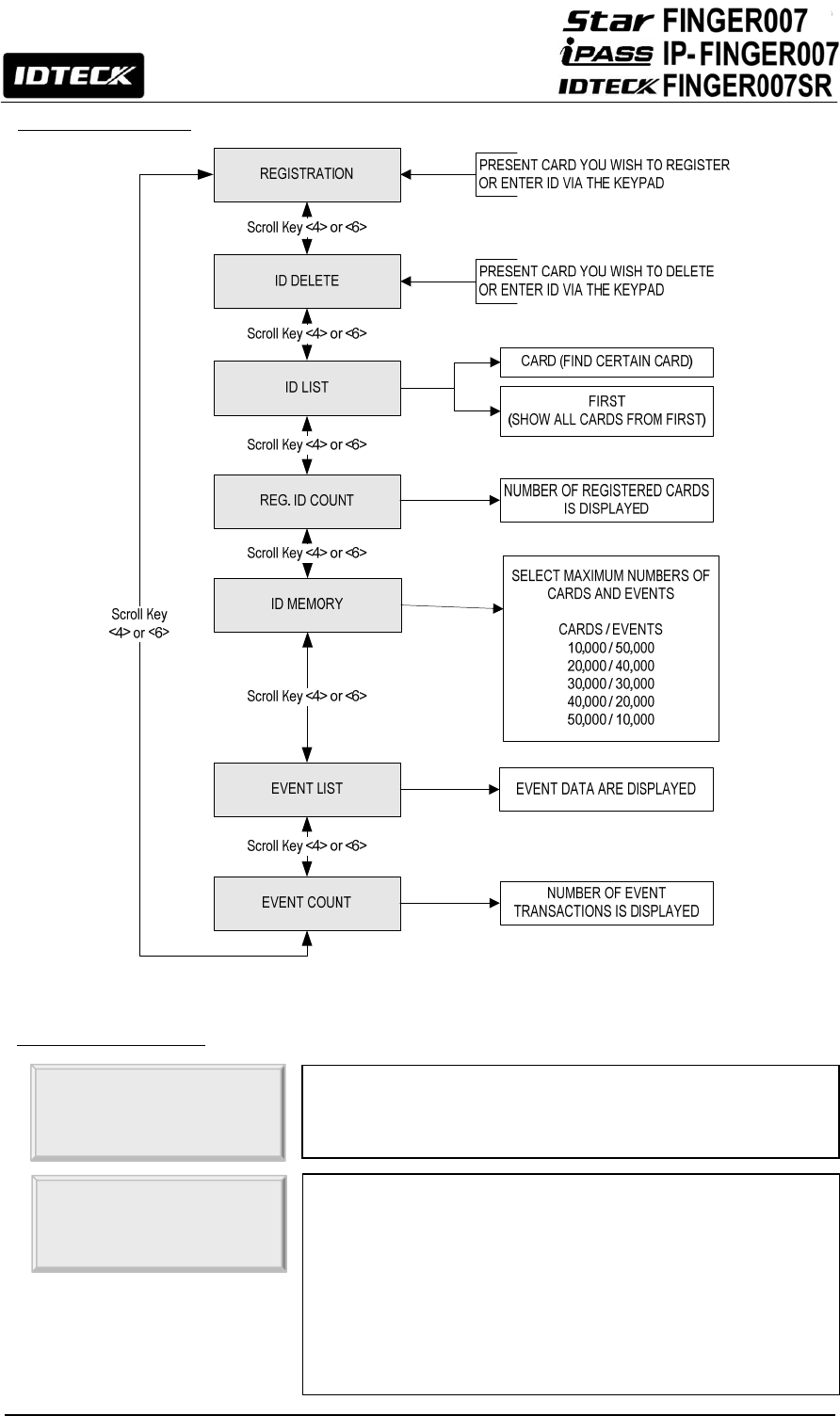
47
12.3 Setup Menu F3
12.3.1 ID Registration
1. REGISTRATION
ENTER ID NO.
- > _
Registration allows you to add new cardholders to the
FINGER007. To add a new cardholder ID, press <ENT>.
Either present a card you wish to register to the FINGER007 or
enter the card number (ID) via the keypad and press <ENT>.
NOTE: A Card Number (ID) can be 4 to 8Digits long. For the
FINGER007SR, it can be 4 to 10Digits long. For more
information about the Card Number Range on the
FINGER007SR, see the note under 12.2.14 Data BYTE.

48
12.3.2 ID Deletion
ID: 12345678
PW■__TS__RD_FP_
TO REGISTER F/P
PUT YOUR FINGER!
Once the Card Number is entered, enter the Password (PW),
Time Schedule (TS), Reader Number (RD) and Use of Fingerprint
(FP) and press <ENT>. For more information, see below.
If you have entered 1 in the FP field, the fingerprint scanner will
be lit up. Then, place the cardholder’s fingerprint on the scanner.
LIFT AND
PUT YOUR FINGER!
Once the light from the fingerprint scanner is turned off, lift the
finger up and put it back on a while later.
[Q1:3] [Q2:4]
REGISTRATION OK!
If the registration is successful, the “REGISTRATION OK!”
message will be displayed on the LCD. If you have registered the
fingerprint, the quality score for the fingerprint will appear as
shown on the left. If the registration is not successful, the
“REGISTRATION ERR!” Message will be displayed on the LCD.
Description of Fields
z PW (Password): Enter the 4Digit password. Password verification can be enabled in
11.1.4. Reader1 Mode. This field is compulsory even if you do not use password
verification.
z TS (Time Schedule): If you wish to apply a certain time schedule to the cardholder,
enter the T/S code. If you wish to allow the cardholder round-the-clock access, enter 0.
z RD (Reader Assignment Code): To use both Readers1 and 2 for the cardholder. Enter
0(or 3). To use just Reader1, enter1. To use just Reader2, enter2.
z FP (Fingerprint): To register the cardholder’s fingerprint, enter1. If you do not wish to
register the cardholder’s fingerprint, enter 0.
2.ID DELETE
ENTER ID NO.
- >
ID Delete allows you to delete existing cards from the
FINGER007. To delete an existing card (Or ID), press <ENT>.
Either present a card you wish to delete to the FINGER007 or
enter the card number (ID) via the keypad and press <ENT>.

49
12.3.3 ID List
12.3.4 Registered ID Count
ID: 12345678
DELETE SUCCESS!
If the card was successfully deleted, the “DELETE SUCCESS!”
message will be displayed on the LCD. If the card you
presented or the card number you entered is not found, the
“UNREGISTERED ID” message will be displayed.
3. ID LIST
3. ID LIST
1: CARD 2: FIRST
ID List allows you to search for a certain registered card or
view the list of all registered cards. To begin, press <ENT>
To search for a certain registered card, press <1>. To view the
entire list of all registered cards, press <2>.
ID: 12345678
PW1234TS00RD0FP1
The LCD will show the information of the card you have
selected in the previous step or the first card on the list. Press
<4> or <6> to view the information of the previous or next card.
The “FIRST ID” or “LAST ID” message will appear if you are
viewing the first or last ID. If there is no card data, the LCD will
display the “MEMORY EMPTY” message.
If your FINGER007 is set in Reader Mode, the TS and RD
values are not valid and the LCD will display “TS00RD3”.
ENTER ID NO.
- >
If you have entered <1>, enter the Card Number (ID) or
present the card you wish to view the information of.
4. REG. ID COUNT
00123
The number of registered user IDs is displayed. This count
automatically increases or decreases as IDs are registered or
deleted. The LCD on the left shows that the total of 123 user
IDs are re
g
istered in the memor
y
.

50
12.3.5 ID Memory
12.3.6 Event List
6.EVENT LIST
ID:00000000 R:1
08100840242050A
Event List allows you to check the past access events with
the information such as card number, time and date, etc.
The LCD displays the information of the access events as
follows; Card Number (ID), Reader Number (R: 1 – Reader
1), Event Date (YY/MM/DD), Day of the Week (4: Wed), Time
(hh/mm/ss), Access Status (0: Access granted) and Function
Key Value (A=F1).
MEMORY EMPTY!!
Press <4> or <6> to view the information of the previous or
next event transaction. The “FIRST EVENT” or “LAST EVENT”
message will appear if you are viewing the first or last event. If
there is no event data, the LCD will display the “MEMORY
EMPTY” message.
5. ID MEMORY
10000/50000
ID Memory allows you to decide how to divide the memory
space between IDs and event transactions. The total number
of IDs and event transactions combined is a maximum of
60,000. The default setting is 10,000 users and 50,000 event
transactions. If you increase the maximum number of IDs, the
maximum number of events decreases in the same
proportion, and vice versa. To change the memory partition
setting, press <ENT>, and press <4> or <6> to select
10000/50000, 20000/40000, 30000/30000, 40000/20000 or
50000/10000 (No. of IDs / No. of Events), and then press
<ENT> again to confirm.
NOTE: The event memory must be emptied prior to changing
this setting. If you attempt to change the setting with some
event data still in the memory, the LCD will display “EVENT
MEMORY NOT EMPTY” error message.
NOTE: If you attempt to reduce the ID memory size to a value
lower than the current number of IDs stored in the memory,
the LCD will display the “ID TOTAL COUNT WRONG” error
message.
5. ID MEMORY
-> 10000/50000
EVENT MEMORY
NOT EMPTY !!!
ID MEMORY NOT
EMPTY !!!

51
12.3.7 Event Count
7.EVENT COUNT
12345
The number of event transactions is displayed. This count
automatically increases or decreases as new events occur or
the existing events are uploaded to the PC. The LCD on the
left shows that the totals of 12345 event transactions are
stored in the memory.
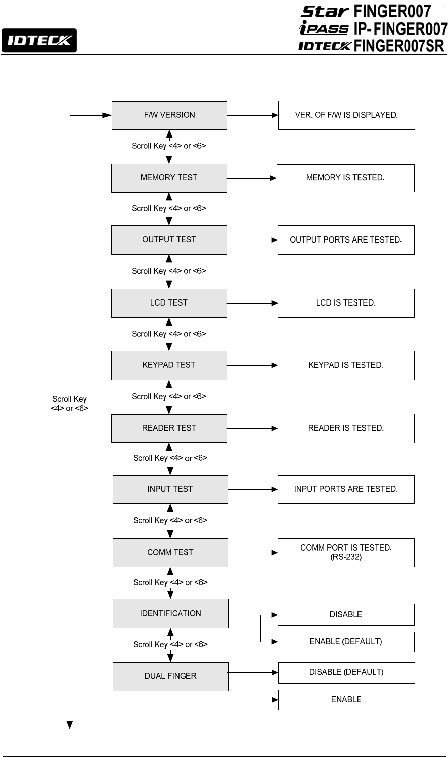
52
12.4 Setup Menu F4
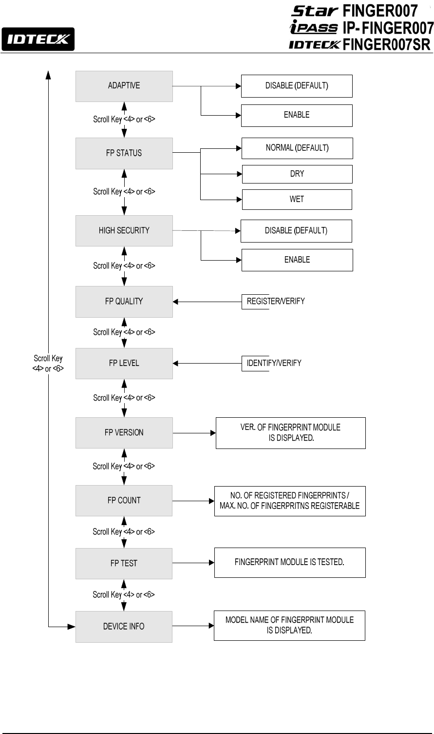
53
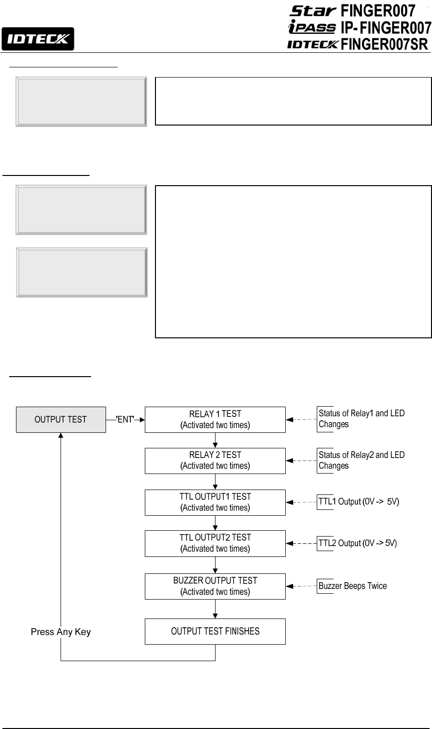
54
12.4.1 Firmware Version
12.4.2 Memory Test
12.4.3 Output Test
1. F/W VERSION
V A.1.0
The version of the firmware installed in the FINGER007 is
displayed on the LCD.
2. MEMORY TEST Memory Test allows you to test the memory of the
FINGER007. To begin the test, press <ENT>. If the test is
successful, the LCD will display the “TEST PASSED”
message. Press any key to finish the test. If the test is
unsuccessful, the LCD will display the “TEST FAILED”
message. Press any key to finish the test and try again. If the
problem persists, please contact your local IDTECK dealer for
assistance or service.
TEST FAILED!!!
PRESS ANY KEY…

55
12.4.4 LCD Test
12.4.5 Keypad Test
3. OUTPUT TEST Output Test allows you to test the output ports of the
FINGER007. To begin the test, press <ENT>. First, output
ports1 and 2 will be tested. During the test, relay outputs are
activated and you will hear Tick-Tack sounds with the green
LED blinking twice. Second, output oorts3 and 4 will be
tested. During the test, TTL outputs are activated and the
yellow LED blinks twice. You can check the voltage level of
the TTL outputs with appropriate test equipment. Lastly,
output port 5 will be tested. During the test, you will hear 2
beeps. After all the tests are over, press any key to exit.
OUTPUT 1
OFF
PRESS ANY KEY…
4. LCD TEST LCD Test allows you to test the LCD of the FINGER007. To
begin the test, press <ENT>. Once the test begins, the LCD
will display a series of different screens. Ensure that all the
screens on the LCD are properly displayed. The test ends
with the display of the firmware update date (YYYY/MM/DD).
After the test is finished, press any key to exit.
AAAAAAAAAAAAAAA
CCCCCCCCCCCCCCC
5. KEYPAD TEST Keypad Test allows you to test the keys on the keypad. To
begin the test, press <ENT>. Press each key on the keypad,
then the number or letter that corresponds to the key pressed
will disappear from the screen. After all the keys are pressed,
the LCD displays the “TEST PASSED” message.
NOTE: Letter A corresponds to <ESC>, B to <ENT>, C to
<F1>, D to <F2>, E to <F3>, and F to <F4>.
5. KEYPAD TEST
0123456789ABCDEF
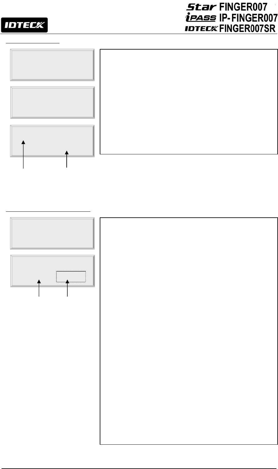
56
12.4.6 Reader Test
12.4.7 Input / DIP Switch Test
6. READER TEST Reader Test allows you to test the reader(s). To begin the
test, press <ENT>. While the LCD displays “SCANNING”,
present a card to the reader you would like to test, and the
LCD will display the reader number and the card number.
After the test is finished, press <ESC> to exit.
NOTE: Reader#1 refers to the built-in reader of the
FINGER007, and Reader #2 refers to an external reader.
NOTE: You can also use Reader Test to check the number of
a card.
SCANNING…
READER #1
12345678
7. INPUT TEST Input Test allows you to check the status of Input Ports and DIP
switches (Communication Address Setting Switches). To begin the
test, press <ESC>.
1. DIP Switch: 1=ON, 2=OFF (It shows how the DIP
switch on the back of the FINGER007 is set.)
2. Input 1-4: 0=OFF (Disabled)
Input 1-4: 1=ON (Enabled)
Input 1-4: 2=Input Disconnected
3. Input 5: The status of the tamper switch inside the
FINGER007 (0=OFF (Disabled), 1=ON (Enabled))
4. Input 6: The status of the Proximity Sensor
(0=OFF (Disabled), 1=ON (Enabled))
If you activate the Cut-Off Check feature for all the input ports
in “5.IN/OUT DEFINE” from F2 Setup menu, the result of an
input port test will change to 222200 (If termination resistors
are not connected) or 000000 (If termination resistors are
connected).
INPUT TEST
10000100 000000
Card No.
Reader No.
In
p
ut Port
DIP Switch

57
12.4.8 Communication Test
12.4.9 Identification Mode
12.4.10 Dual Fingerprint Mode
DUAL
FINGER Number of Templates and Fingers Authentication
Success Ratio
Recommended
Authentication Mode
NOT USE 2 Storage Templates for a single finger. High Identification Mode
USE 1 Storage Template each for 2 different fingers.
Low Verification Mode
8. COMM TEST COMM Test allows you to test communication. Prior to the
test, connect the RS232-RX wire (Black wire with White stripe)
and the RS232-TX wire (Red wire with Black stripe) together.
To begin the test, press <ENT>. If the test is successful, the
LCD will display the “TEST PASSED” message. Press any
key to finish the test. If the test is unsuccessful, the LCD will
display the “TEST FAILED” message. Press any key to finish
the test and try again after powering the FINGER007 off and
back on.
TEST PASSED!!!
PRESS ANY KEY…
9. IDENTIFICATION Identification Mode is a feature that allows users to use just
fingerprint verification without having to present their cards or
enter their ID numbers. If this feature is enabled, a user can
just place the fingerprint onto the fingerprint scanner, and then
the FINGER007 will perform 1: N authentication for the entire
fingerprint templates in the database and grant access if a
fingerprint template that matches the user’s fingerprint is
found.
Default Setting is ‘USE’.
9. IDENTIFICATION
- > USE
10. DUAL FINGER The Dual Fingerprint Mode allows one user to register two
different fingerprints per ID. This feature is useful when a
user’s finger is injured and wishes to use the other registered
finger in the verification process.
To enable or disable the Dual Fingerprint Mode, press <ENT>
and press <4> or <6> to select “ENABLE” or “DISABLE” and
press <ENT> to confirm.
10. DUAL FINGER
- > DISABLED
TEST FAILED!!!
PRESS ANY KEY…

58
12.4.11 Adaptive Mode
12.4.12 FP Status
12.4.13 High Security
11. ADAPTIVE The Adaptive Mode is a feature that improves the quality of
fingerprint images in the authentication process, guaranteeing
a higher likelihood of successful authentication. However, the
authentication process may take longer with this feature on.
To enable or disable the Adaptive Mode, press <ENT> and
press <4> or <6> to select “USE” or “NOT USE” and press
<ENT> to confirm.
11. ADAPTIVE
- > NOT USE
12. FP STATUS
NORMAL
FP Status is a special feature designed for special
environments where the fingers of most employees might be
too dry or wet. If you set the FP Status setting to dry or wet,
the FINGER007 will adjust the fingerprint images according to
the environment to improve the authentication rate.
To change the setting, press <ENT> and press <4> or <6> to
select “NORMAL”, “DRY” or “WET” and press <ENT> to
confirm.
12. FP STATUS
- > DRY
13. HIGH SECURITY High Security allows you to enable or disable the latent
fingerprint image processing.
Default setting is ‘NOT USE’.
CAUTION: Since the image of a latent fingerprint and that of
a dry fingerprint are both equally faint, it is hard to tell dry
fingerprints from latent images. Therefore, enabling High
Security will lower the recognition success rate of dry
fingerprints as they might be mistaken to be latent
fingerprints.
NOTE: In a place where many users have dry fingerprints, a
better recognition success rate can be achieved by adjusting
the exposure value higher and/or enabling Adaptive Mode.
13. HIGH SECURITY
- > NOT USE

59
12.4.14 FP Quality
12.4.15 FP Level
12.4.16 Fingerprint Module Version
12.4.17 Fingerprint Count
15. FP LEVEL
8 / 5
Verify / Identify Security Level is the threshold value for
fingerprint authentication. By adjusting the setting value, you
can achieve either a higher recognition success rate or a
higher security level.
NOTE: If you want to change this function, please consult
with IDTECK. Otherwise the recognition success rate is not
guaranteed.
IDENTIFY / VERIFY
8 / 5
16. FP VERSION
V1.71
FP Version allows you to check the version of the fingerprint
module on your FINGER007.
17. FP COUNT
0000/1000
FP Count allows you to see how many fingerprints are
registered in your FINGER007 and how many can be
registered in total. Depending on the specification of the
fingerprint module in use, the total fingerprint capacity can be
1000, 2000 or 4000 fingerprints.
14. FP QUALITY
40 / 30
Register Quality and Verify Quality are the threshold values
for fingerprint image capture in the fingerprint registration
enrollment process (Register Quality) and verification process
(Verify Quality). If the quality value for a capture fingerprint
image is below the Register Quality threshold, the
authentication (registration or verification) is rejected. By
adjusting the threshold value, you can control the desired
level of fingerprint image quality.
NOTE: If you want to change this function, please consult
with IDTECK. Otherwise the recognition success rate is not
guaranteed.
REGISTER / VERIFY
40 / 30
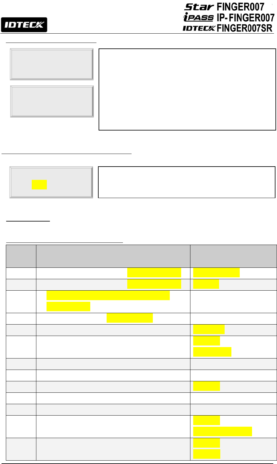
60
12.4.18 Fingerprint Module Test
12.4.19 Fingerprint Device Information Check
13. Appendix
13.1 Default settings of operation modes
No Operation Mode (Mode Name) Default Value
1 READER #1 Operation Mode (READER 1 MODE) ID(RF) + FP(PW)
2 READER #2 Operation Mode (READER 2 MODE) RF ONLY
3 External & Internal Reader Keypad Input Limit
(RF PIN INPUT) NOT USE
4 Use of Event Memory (EVENT ALARM) USE
5 Unit of Time for Output Ports (OUTPUT TIME) UNIT: 1 sec
6 Application Mode to Output Port Time Schedules
(OUTPUT T/S)
NOT USE
(all codes: 00)
7 Anti-Pass Back Feature (APB SETUP) NOT USE
8 Duress Mode (DURESS MODE) NOT USE
9 Door Open Alarm Time (DOOR ALARM) 3 sec (03)
10 Time Schedule (TIME SCHEDULE) All Time (00:00)
11 Holiday (HOLIDAY T/S) All Date (00:00)
12 Holiday Code (HOLIDAY CODE) NOT USE
(all holiday codes: 00)
13 Time Schedule Assigned to Internal & External
Reader (READER T/S)
NOT USE
(code: 00)
19. DEVICE INFO
FIM2260-HD
Device Info shows you the model name of the fingerprint
module on your FINGER007.
18. FP TEST FP Test allows you to test the fingerprint module on your
FINGER007. To begin the test, press <ENT>. If the test is
successful, the “TEST PASSED” message will be displayed. If
the test is unsuccessful, the LCD will display the “TEST
FAILED” message. If that is the case, try again. If the problem
persists, please contact your local IDTECK dealer for
assistance or service.
TEST PASSED!!!
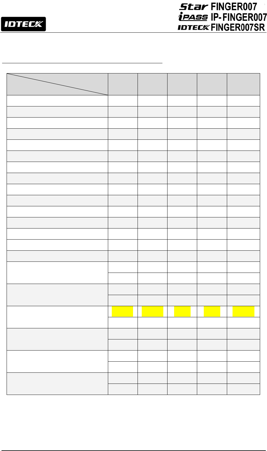
61
13.2 Default Output Settings for Input / Output Relations
OUTPUT
INPUT Relay#1
Relay#2
TTL#1 TTL#2 BUZZER
[1] Input #1(EXIT BUTTON) 03 00 00 00 00
[2] Input #2(Door Contact SW) 00 99 00 00 99
[3] Input #3 00 00 00 00 00
[4] Input #4 00 00 00 00 00
[5] Input #5(TAMPER S/W) 00 99 00 00 99
[6] Reader#1 ID OK 03 00 00 00 00
[7] Reader#1 ID Error 00 03 00 00 00
[8] Reader#1 ID T/S Error 00 03 00 00 00
[9] Reader#1 APB Error 00 03 00 00 00
[10] Reader#2 ID OK 03 00 00 00 00
[11] Reader#2 ID Error 00 03 00 00 00
[12] Reader#2 ID T/S Error 00 03 00 00 00
[13] Reader#2 APB Error 00 03 00 00 00
[14] DURESS MODE 03 00 00 00 00
[15] OUTPUT TIME SCHEDULE 00 00 00 00 00
[16] INPUT TIME SCHEDULE Input #1
Input #2
Input #3
Input #4 Input #5
00 00 00 00 00
[17] DR OPEN ALARM Relay#1
Relay#2
TTL#1 TTL#2 BUZZER
00 03 00 00 00
[18] CUT OFF ALARM Relay#1 Relay#2 TTL#1 TTL#2 BUZZER
00 03 00 00 00
[19] INPUT EVENT Input #1
Input #2
Input #3
Input #4 Input #5
01 01 01 01 01
[20] EMERGENCY IN Input #1
Input #2
Input #3
Input #4 Input #5
00 00 00 00 00
[21] CUT OFF CHECK Input #1
Input #2
Input #3
Input #4 Input #5
00 00 00 00 00
* Index No. [1] - [14], [17]-[18]
The values indicate the operating time of each output for the input signal.
99 denote “Operating time is not limited”.
* Index No. [15]
The values indicate the Time Schedule Code (index) applied to each output.

62
* Index No. [16]
The values indicate the Time Schedule Code (index) applied to each input.
* Index No. [19]-[21]
The values indicate whether to enable or disable the feature for each output.
(01-USE, 00-NOT USE)
14. FCC Registration Information
FCC Requirements Part 15
CAUTION: Any changes or modifications in construction of this device which are not expressly
approved by the responsible for compliance could void the user's authority to operate the equipment.
NOTE: This device complies with Part 15 of the FCC rules.
Operation is subject to the following two conditions;
1. This device may not cause harmful interface, and
2. This device must accept any interference received, including interference that may cause
undesired operation.
This equipment has been tested and found to comply with the limits for a Class A Digital Device,
pursuant to Part 15 of the FCC rules. These limits are designed to this equipment generates, uses,
and can radiate radio frequency energy and, if not installed and used in accordance with the
instructions, may cause harmful interference to radio communications.
However, there is no guarantee that interference will not occur in a particular installation. If this
equipment does cause harmful interference to radio or television reception, which can be determined
by turning the radio or television off and on, the user is encouraged to try to correct interference by
one or more of the following measures.
1. Reorient or relocate the receiving antenna.
2. Increase the separation between the equipment and receiver.
3. Connect the equipment into an outlet on another circuit.
4. Consult the dealer or an experienced radio/TV technician for help.

63
15. Warranty Policy and Limitation of Liability
IDTECK warrants this product against defects in material and workmanship for the period specified
below from the date of purchase under normal customer use. This Warranty doesn’t apply: 1) to any
product which has been dismantled without authorization of IDTECK or/and has a damaged or
detached QC label on its back side; 2) to any losses, defects, or damages caused by improper
testing, operation, installation, maintenance, modification, alteration, or adjustment; 3) to any product
with a damaged or faded serial number on it; or 4) to any losses, defects, or damages caused by
lightning or other electrical discharge, natural disaster, misuse, accident or neglect.
This Limited Warranty is in lieu of all other warranties, obligations, or liabilities on the part of IDTECK,
and IDTECK DISCLAIMS ANY AND ALL WARRANTY, WHETHER EXPRESS OR IMPLIED, OF
MERCHANTABILITY OR FITNESS FOR A PARTICULAR PURPOSE.IDTECK does not, and cannot,
know who is present, what property is located, where this product will be used; it would be extremely
difficult to determine the actual damages that may result from a failure of the product to perform as
anticipated; and the low price of this product is based upon the nature of the product provided and
the limited liability that IDTECK assumes. IDTECK IS NOT RESPONSIBLE FOR ANY PERSONAL
INJURY, PROPERTY DAMAGE OR LOSS, DIRECT, SPECIAL, INCIDENTAL OR
CONSEQUENTIAL DAMAGES, OR OTHER LOSS, AND IDTECK’S MAXIMUM LIABILITY SHALL
NOT IN ANY CASE EXCEED THE PURCHASE PRICE OF THE PRODUCT.
To obtain repair or replacement under the terms of this warranty, visit IDTECK’s Website
(http://www.idteck.com) and place an online RMA request. After an RMA code is issued, return
the product along with the authorization RMA code.
>> Warranty Period
Product Category Warranty
Period
1 RF CARDS (ACTIVE TYPE) 1 year
FINGERPRINT MODULE / SENSOR
2 RF READERS (WITHOUT EPOXY POTTING)
2 years
3 STANDALONE CONTROLLERS
4 CONTROL PANELS
5 FINGERPRINT READERS
6 RF READERS (WITH EPOXY POTTING) Lifetime
7 RF CARDS (PASSIVE TYPE)

64
This device complies with part 15 of the FCC Rules. Operation is subject to the following two conditions:
(1) this device may not cause harmful interference; and (2) this device must accept any interference
received, including interference that may cause undesired operation.
This equipment has been tested and found to comply with the limits for a Class A digital device, pursuant
to part 15 of the FCC Rules. These limits are designed to provide reasonable protection against harmful
interference when the equipment is operated in a commercial environment. This equipment generates,
uses, and can radiate radio frequency energy and, if not installed and used in accordance with the instruction
manual, may cause harmful interference to radio communications. Operation of this equipment in a residential
area is likely to cause harmful interference in which case the user will be required to correct the interference
at his own expense. Change or modifications not expressly approved by the party responsible for compliance
could void the user’s authority to operate the equipment under FCC rules.

65
16. How to Make RMA Request (After Sales Service)
To make the RMA request, the product must be initially registered on IDTECK webpage. After
registering the product, send it to IDTECK RMA Center.
Please follow the instructions below:
1. Please register the RMA request via IDTECK webpage.
: www.idteck.com Æ “Support & Download” Æ “Online RMA” Æ “RMA REQUEST”
(Please refer to the IDTECK webpage for more details.)
2. RMA Code will be issued after the RMA Center reviews the RMA request form.
3. Enclose the product along with the RMA Code and send it to IDTECK RMA Center.
(Product without RMA Code is not accepted.)
If you have any questions or problems regarding the RMA services, please contact us using the
contact information below. Friendly representatives at IDTECK are always standing by to provide the
best after sales services.
IDTECK Headquarter
5F, Ace Techno Tower B/D, 684-1, Deungchon-Dong,
Gangseo-Gu, Seoul, 157-030, Korea
Tel: +82-2-2659-0055
Fax: +82-2-2659-0086
E-mail: webmaster@idteck.com
Website: www.idteck.com
E-Training Center: http://www.idtecktraining.com
IDTECK Production Facility and RMA Center
3F, 10/10-1/10-2, Dodang-Dong,
Weonmi-Gu, Bucheon-Si, Gyeonggi-Do 420-130, Korea
Tel: +82-2-2659-0055
Fax: +82-2-2659-0086
E-mail: webmaster@idteck.com
Website: www.idteck.com
E-Training Center: http://www.idtecktraining.com
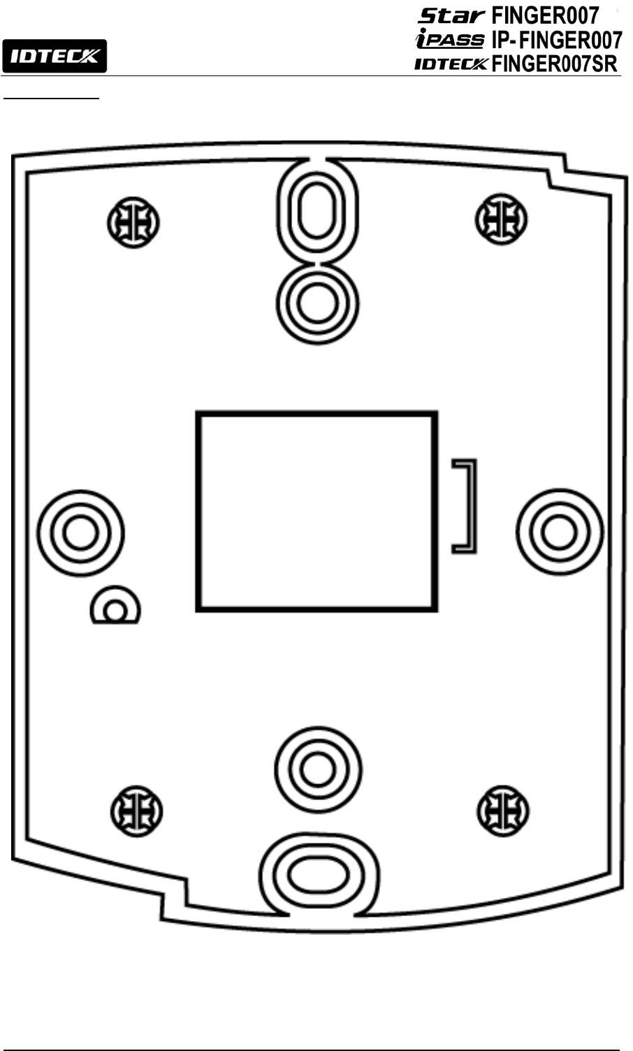
66
17. Template

Jan. 2011 Copyright ©2011 IDTECK Co., Ltd.
The specifications contained in this manual are subject to change without notice at any time.
5F, Ace Techno Tower B/D, 684-1, Deungchon-Dong,
Gangseo-Gu, Seoul, 157-030, Korea
Tel : +82-2-2659-0055
Fax : +82-2-2659-0086
E-mail : webmaster@idteck.com