ID Teck Co GE314 Fingerprint Access Controller User Manual 7
ID-Teck Co Ltd Fingerprint Access Controller 7
UserManual.wiki
>
ID Teck Co
>
GE314 User Manual
Users Manual
Navigation menu
Upload a User Manual
Namespaces
Wiki Guide
HTML
PDF
Info
Views
User Manual
Discussion / Help
Navigation
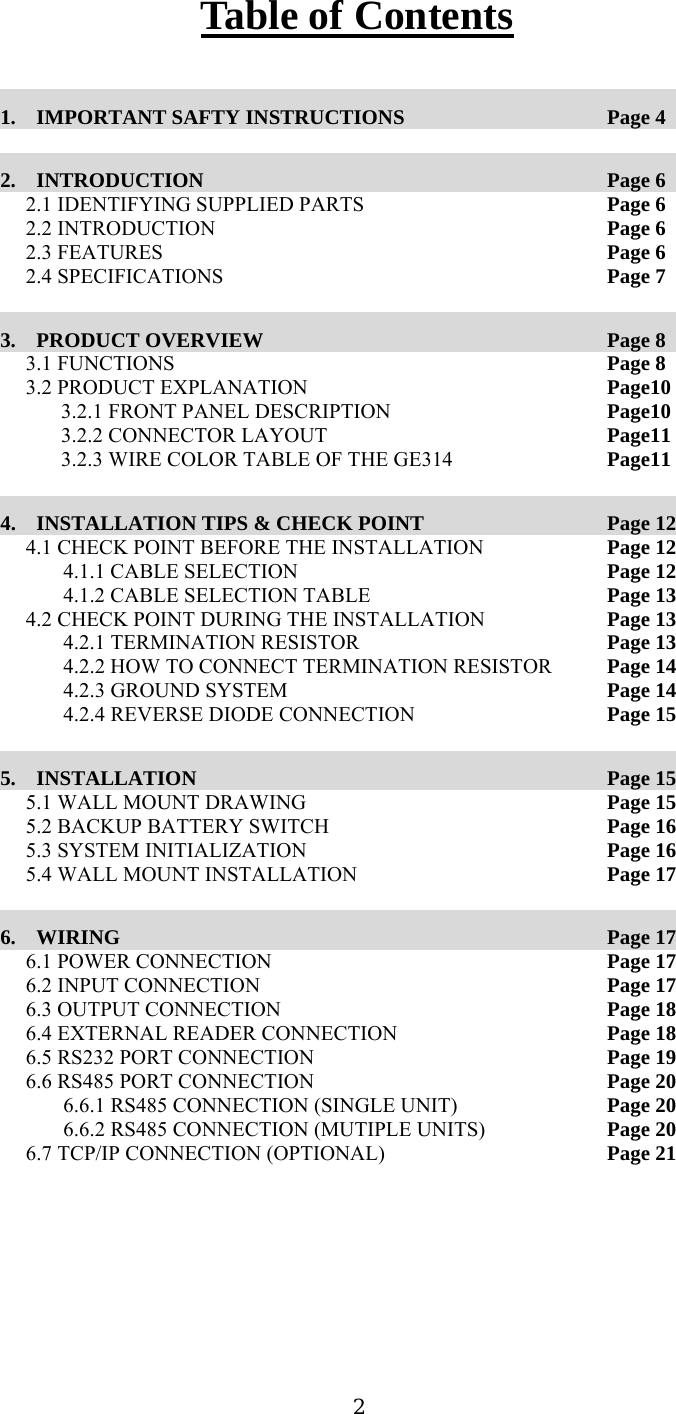

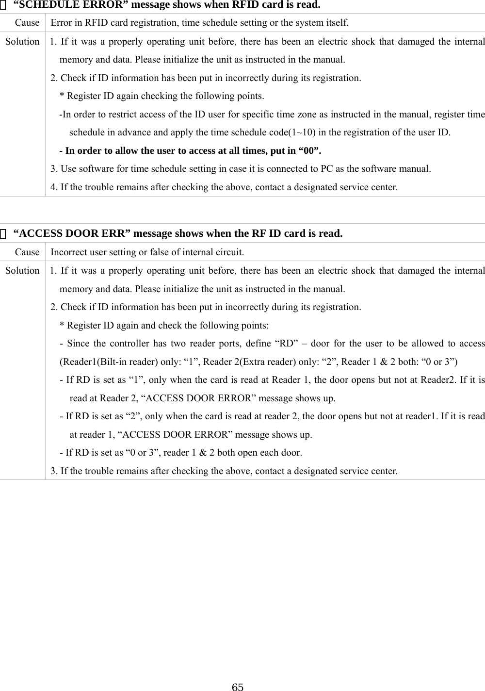
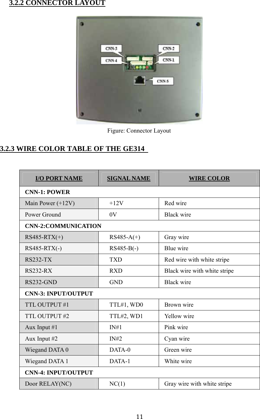
![3.2 PRODUCT EXPLANATION 3.2.1 FRONT PANEL DESCRIPTION LCD System Operation Status LED Fingerprint Scanner 24 key pad Function key Figure: Description of GE314 Front Panel LCD Module: LCD module display GE314 status. System Operation Status LED: When the power is applied to GE314, the red LED is turned on. When the Relay #1 is operated, the green LED is turned on. When the Relay #2 is operated, the yellow LED is turned on. 24 key pad: You can operate GE314 manually by using the key pad. Function key: The GE314 has 12 Function keys ([F1] ~ [F12]). 10](https://usermanual.wiki/ID-Teck-Co/GE314/User-Guide-570550-Page-10.png)
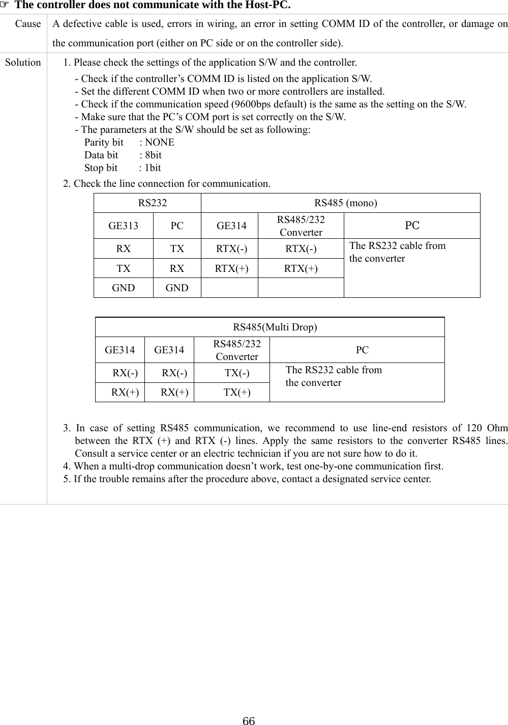
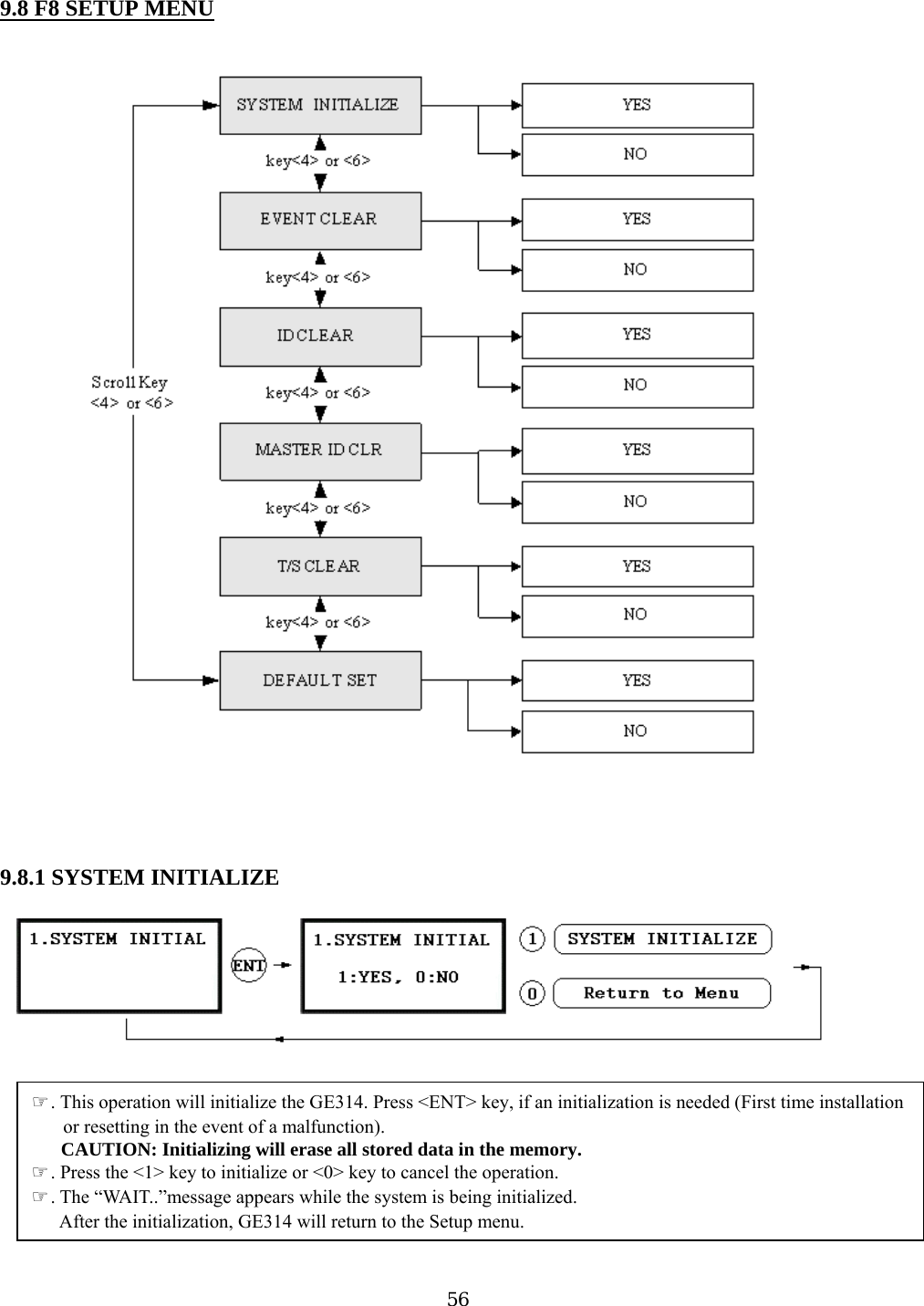
![5.2 BACKUP BATTERY SWITCH GE314 has a switch for the backup battery connection, which remains open circuit to prevent any current consumption of the backup battery (Figure: Switch setting). Before the GE314 operation, it needs to be connected so that the backup battery can retain the serial RTC(Date and Time data) during power failure. Figure: SWITCH SETTING Figure: SWITCH LOCATION 5.3 SYSTEM INITIALIZATION After the all installation and connections are completed, press and hold the Initialize button and put the power (+12V DC) to GE314. The LCD will first display “Initialize OK? 0:No 1:Yes”. Press <1> key if you want to initialize the system. After all Initialization process is completed, the system is operating on normal mode and the LCD displays “GE Security, GE314 [F1], Date Time”. 16](https://usermanual.wiki/ID-Teck-Co/GE314/User-Guide-570550-Page-16.png)
![7. BASIC SETTINGS 7.1 INITIALIZATION OF GE314 After the all installation and connections are completed, press and hold the Initialize button and put the power (+12V DC) to GE314. The LCD will first display “Initialize OK? 1:YES, 0:NO”. Press <1> key if you want to initialize the system. After all Initialization process is completed, the system is operating on normal mode and the LCD displays “GE Security, GE314 [F1], Date Time”. 7.2 HOW TO ENTER THE SETUP MENU To setup or to change the GE314 settings, you have to enter the SETUP MENU first. To do so, press <0> key eight times (Default Master ID ‘00000000’) and <ENT> key from the Keypad. You now entered to the SETUP MENU. There are 9 SETUP MENU and you first get into [F1 SETUP MENU]. You can move to another SETUP MENU by pressing <F1> key to <F9> key button. For example, if you want to go to [F2 SETUP MENU] then press <F2> key, for [F5 SETUP MENU] then press <F5> key and so on. There are several SUBMENU on each SETUP MENU and you can scroll up and down the SUBMENU by pressing <4> and <6> key on each SETUP MENU. If you don’t press any key for 60 seconds or if you press <ESC> key, GE314 will exit the SETUP MENU and return to normal operation mode. You can also change the Master ID in the [F4 SETUP MENU]. 22](https://usermanual.wiki/ID-Teck-Co/GE314/User-Guide-570550-Page-22.png)
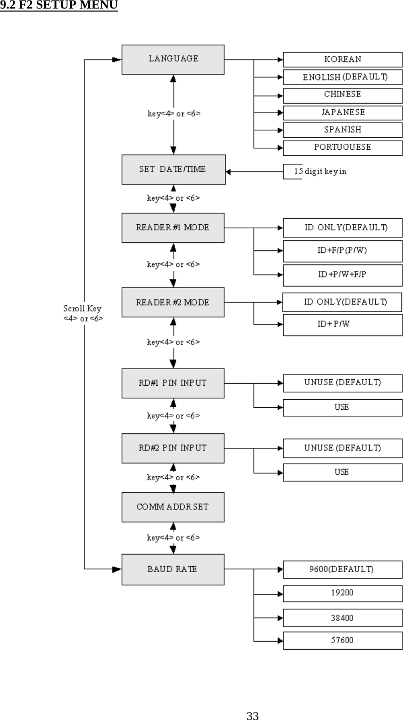
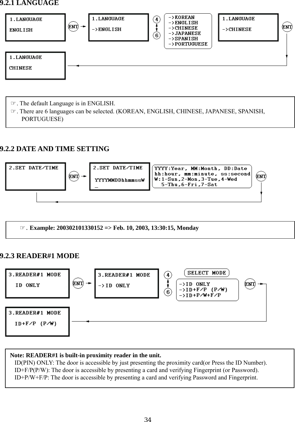
![7.3 LANGUAGE SETTING Select [LANGUAGE] in the [F2 SETUP MENU] then press <ENT> key to select the LANGUAGE. Please follow the steps below for LANGUAGE setting and following procedure is for selecting CHINESE. 7.4 DATE/TIME SETTING Select [SET DATE/TIME] in the [F2 SETUP MENU] and enter Year / Month / Date / Hour / Minute / Second / Day (Total 15 digits) as shown below. The LCD will display the new Date and Time after the time setting is completed but the year and day will not be displayed. GE314 has a 24 hours system and day codes are 1 for Sunday, 2 for Monday, 3 for Tuesday, 4 for Wednesday, 5 for Thursday, 6 for Friday and 7 for Saturday. 23](https://usermanual.wiki/ID-Teck-Co/GE314/User-Guide-570550-Page-23.png)
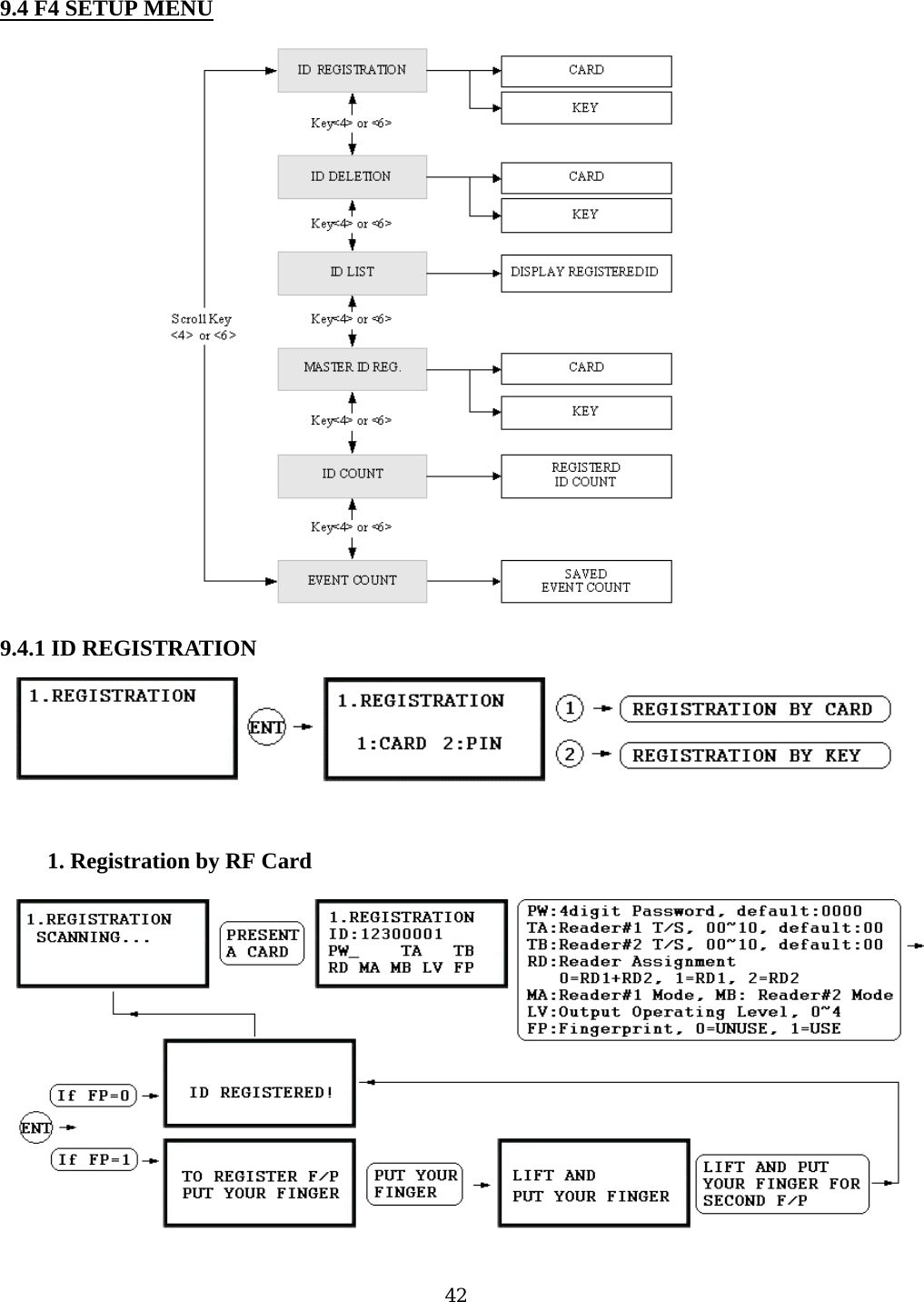
![7.5 ID REGISTRATION You can register the User ID into the GE314. Select [F4 SETUP MENU] -> [REGISTRATION] and follow the steps below. 1. Registration by Card 2. Registration by Key 24](https://usermanual.wiki/ID-Teck-Co/GE314/User-Guide-570550-Page-24.png)
![1. Scanning… The reader is waiting for the ID number to be registered. The card number will appear with a beep sound when you present the card. ID number is 8digit number. 2. ID: ID number consists of 4~8 digit. Enter 4~8digit ID number (PIN) and press <ENT> key on the field. 3. PW: PW is the password which can be used to access the doors with RF + Password operating mode. It is necessary to enter a default password (‘0000’) when you register an ID. 4. TA: TA is the Time Schedule code (‘00’ ~ ‘10’) for the Reader#1 (Built-in Reader). When you present the card to the Reader#1, the cardholder is only allowed the access of the door during the Time intervals of the Time Schedule code entered to TA. To setup the Time intervals for each Time Schedule code, refer to the ard to the Reader#2, the cardholder is only allowed the access of the door during the Time intervals of the the door anytime for the cardholder en enter the default Time Schedule code '00' for the value. n ns ss Door Error”) on the LCD display. A, ‘3’ – ID + Password + Finger Mode ‘1’ – ID Only Mode Time Schedule Setup on the [F5 SETUP MENU]. If you want to access the door anytime for the cardholder then enter the default Time Schedule code '00' for the value. 5. TB: TB is the Time Schedule code (‘00’ ~ ‘10’) for the Reader#2 (Exit Reader). When you present the cTime Schedule code entered to TB. To setup the Time intervals for each Time Schedule code, refer to the Time Schedule Setup on the [F5 SETUP MENU]. If you want to access th 6. RD: RD is the Reader Assignment code for the cardholder. Code ‘0’ assigns for both readers (Built-iReader and Exit Reader), code ‘1’ only assigns Reader#1 (Built-in Reader) and code ‘2’ only assigReader#2 (Exit Reader). If you put ‘1’ for RD (Only Reader#1 assigned) and try to exit through Reader#2(Exit Reader) then GE314 generates an error message (“Acce 7. MA: MA is the Reader#1 (Built-in Reader) Operating Mode for the cardholder. If you put ‘1’ for MReader#1 is always operating on RF Only Mode. ‘0’ – System Operating Mode [F2 SETUP MENU] [READER#1 MODE] ‘1’ – ID Only Mode ‘2’ – ID + Finger(Password) Mode 8. MB: MB is the Reader#2 (Exit Reader) Operating Mode for the cardholder. If you put ‘1’ for MB, Reader#2 is always operating on RF Only Mode. ‘0’ – System Operating Mode [F2 SETUP MENU] [READER#2 MODE] ‘2’ – ID + Password Mode 25](https://usermanual.wiki/ID-Teck-Co/GE314/User-Guide-570550-Page-25.png)
![9utput Operating Level for the cardholder. Output operating time can be set for . LV: LV is the O each user. evel, refer to the Output Setting on the [F7 SETUP MENU]. ‘3’ – Level #3 0. FP: FP is the Fi not. nt 3. hen you enroll or verify y place your finger to the scanner correctly. To setup Output operating time for each l ‘0’ or ‘1’ – Level #1 ‘2’ – Level #2 ‘4’ – Level #4 1ngerprint Usage Flag (1 digit). You can assign the user who uses fingerprint or ‘0’ – User without Fingerpri ‘1’ – User with Fingerprint How to put your finger to the scanner Wour fingerprint, please Figure: How to put your finger to the scanner 26](https://usermanual.wiki/ID-Teck-Co/GE314/User-Guide-570550-Page-26.png)
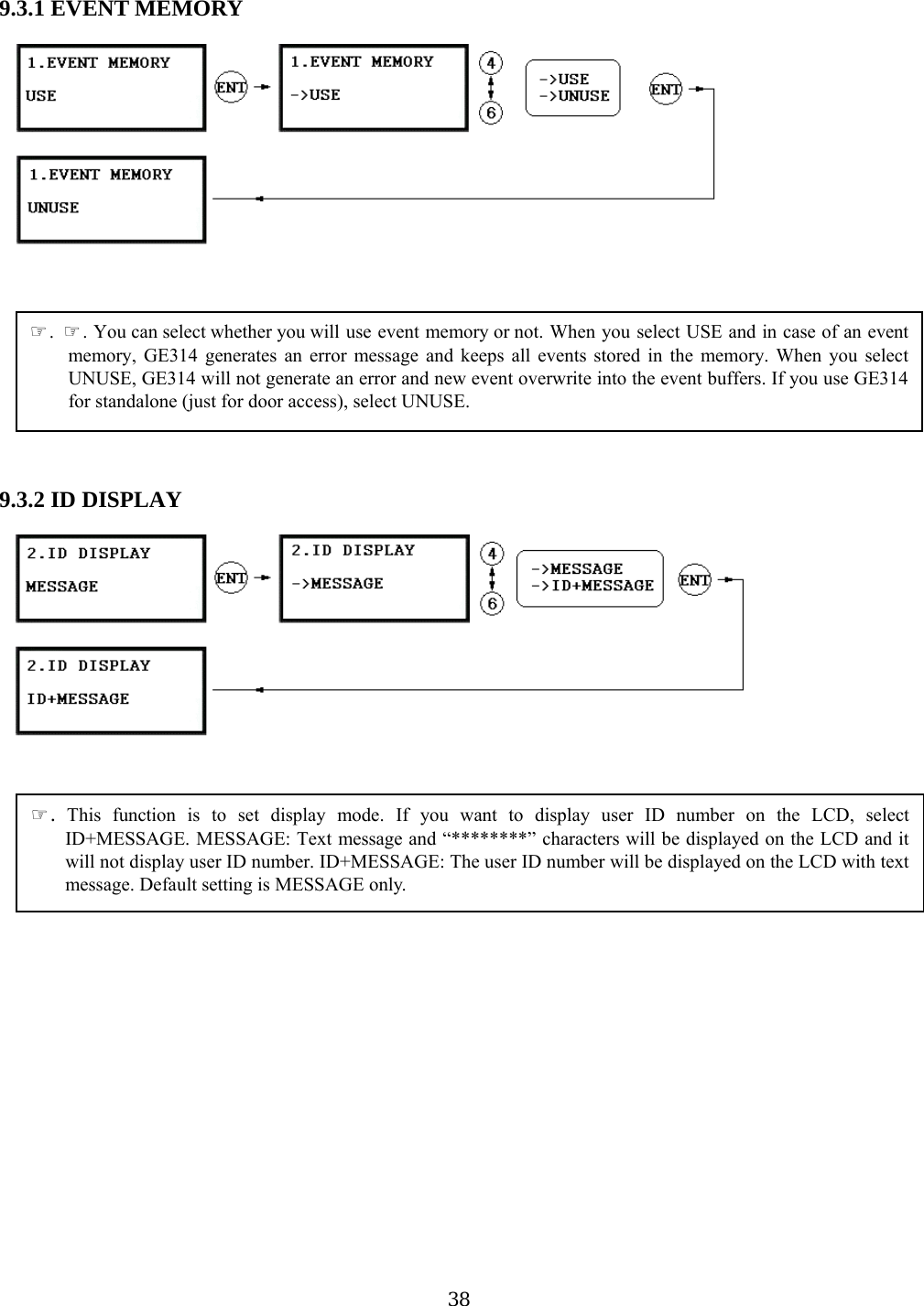
![9 . SETTING CHANGES ☞. To setup or to change the GE314 settings, you have to enter the SETUP MENU first. To do so, press <0> key eight times (Default Master ID ‘00000000’) and <ENT> key from the Keypad. You now entered to the SETUP MENU. There are 9 SETUP MENU and you first get into [F1 SETUP MENU]. You can move to another SETUP MENU by pressing <F1> key to <F9> key button. For example, if you want to go to [F2 SETUP MENU] then press <F2> key, for [F5 SETUP MENU] then press <F5> key and so on. There are several SUBMENU on each SETUP MENU and you can scroll up and down to SUBMENU by pressing <4> and <6> key on each SETUP MENU. If you don’t press any key for 60 seconds or if you press <ESC> key, GE314 will exit the SETUP MENU and return to normal operation mode. You can also change the Master ID in the [F4 SETUP MENU]. 28](https://usermanual.wiki/ID-Teck-Co/GE314/User-Guide-570550-Page-28.png)
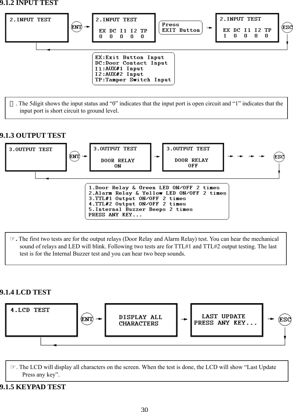
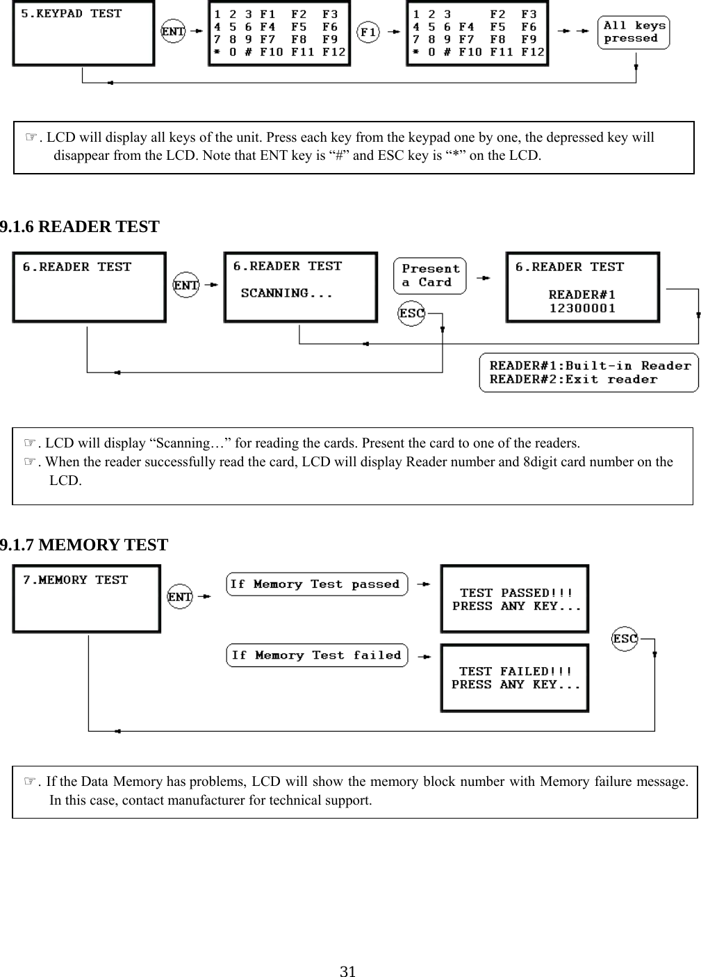
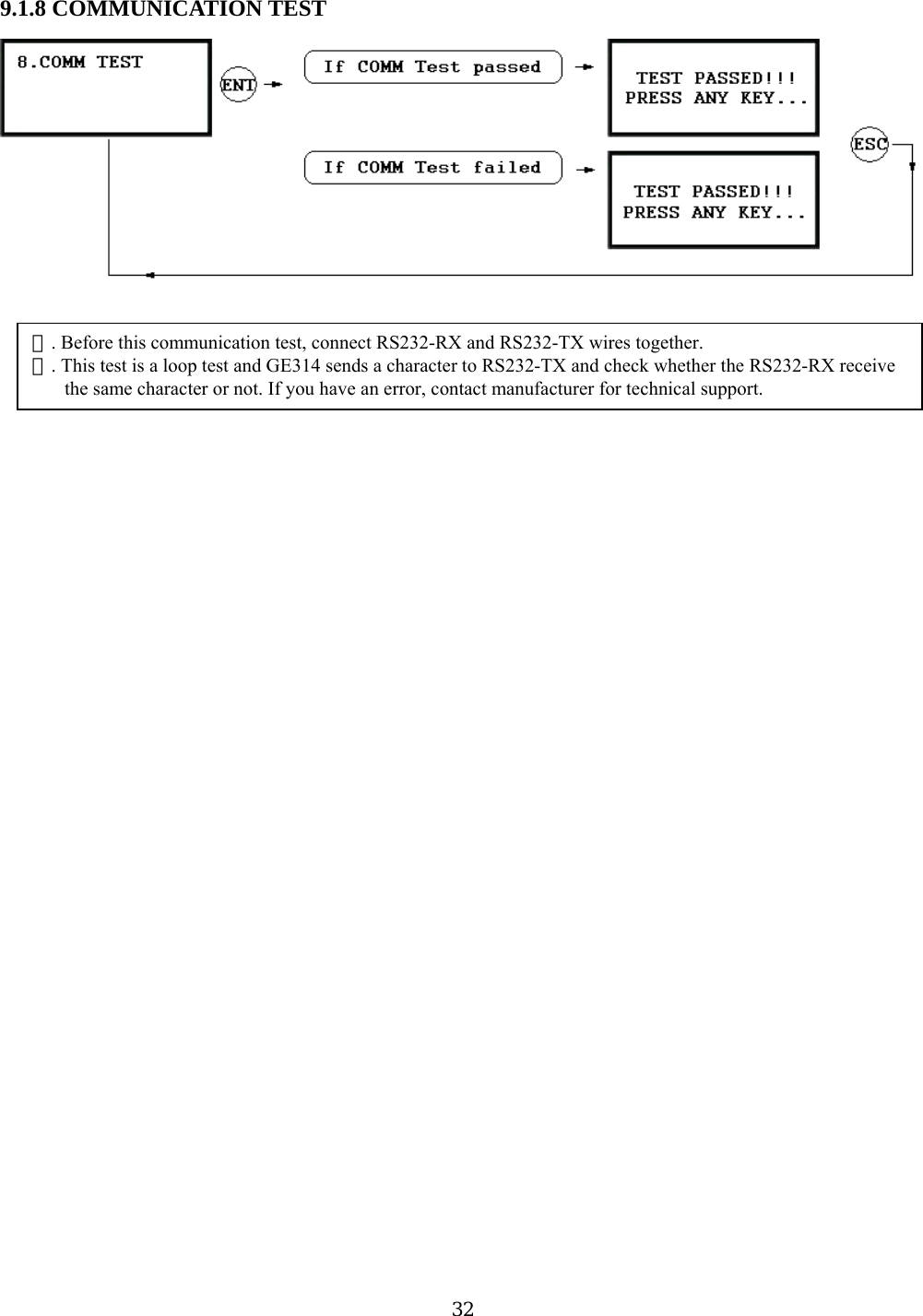
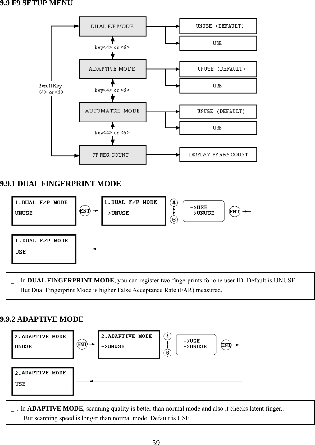
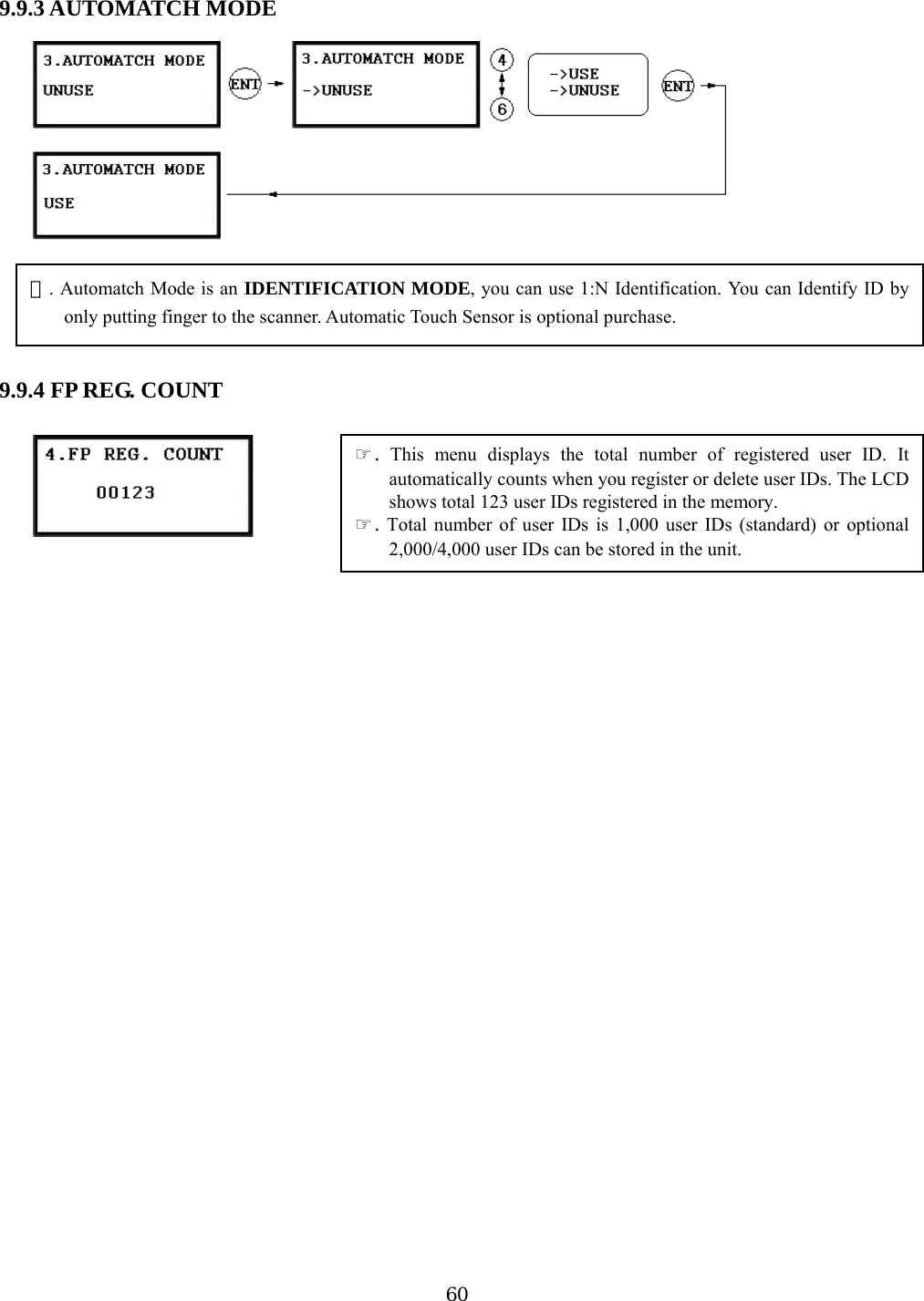
![299.1 F1 SETUP MENU 9.1.1 VERSION CHECK ☞. The Firmware Version of the GE314 displays on the LCD. Press <4> or <6> key to have a look for other menus on [ F1 SETUP MENU]](https://usermanual.wiki/ID-Teck-Co/GE314/User-Guide-570550-Page-29.png)
![43 Keypad 1. Scanning… The reader is waiting for the ID number to be registered. The card number will appear with a beep sound when you present the card. ID number is 8digit number. 2. ID: ID number consists of 4~8 digit. Enter 4~8digit ID number (PIN) and press <ENT> key on the field. 3. PW: PW is the password which can be used to access the doors with RF + Password operating mode. It is necessary to enter a default password (‘0000’) when you register an ID. 4. TA: TA is the Time Schedule code (‘00’ ~ ‘10’) for the Reader#1 (Built-in Reader). When you present the card to the Reader#1, the cardholder is only allowed the access of the door during the Time intervals of the Time Schedule code entered to TA. To setup the Time intervals for each Time Schedule code, refer to the Time Schedule Setup on the [F5 SETUP MENU]. If you want to access the door anytime for the cardholder then enter the default Time Schedule code '00' for the value. 5. TB: TB is the Time Schedule code (‘00’ ~ ‘10’) for the Reader#2 (Exit Reader). When you present the 2. Registration by card to the Reader#2, the cardholder is only allowed the access of the door during the Time intervals of the Time Schedule code entered to TB. To setup the Time intervals for each Time Schedule code, refer to the Time Schedule Setup on the [F5 SETUP MENU]. If you want to access the door anytime for the cardholder then enter the default Time Schedule code '00' for the value. 6. RD: RD is the Reader Assignment code for the cardholder. Code ‘0’ assigns for both readers (Built-in Reader and Exit Reader), code ‘1’ only assigns Reader#1 (Built-in Reader) and code ‘2’ only assigns Reader#2 (Exit Reader). If you put ‘1’ for RD (Only Reader#1 assigned) and try to exit through Reader#2 (Exit Reader) then GE314 generates an error message (“Access Door Error”) on the LCD display. 43](https://usermanual.wiki/ID-Teck-Co/GE314/User-Guide-570550-Page-43.png)
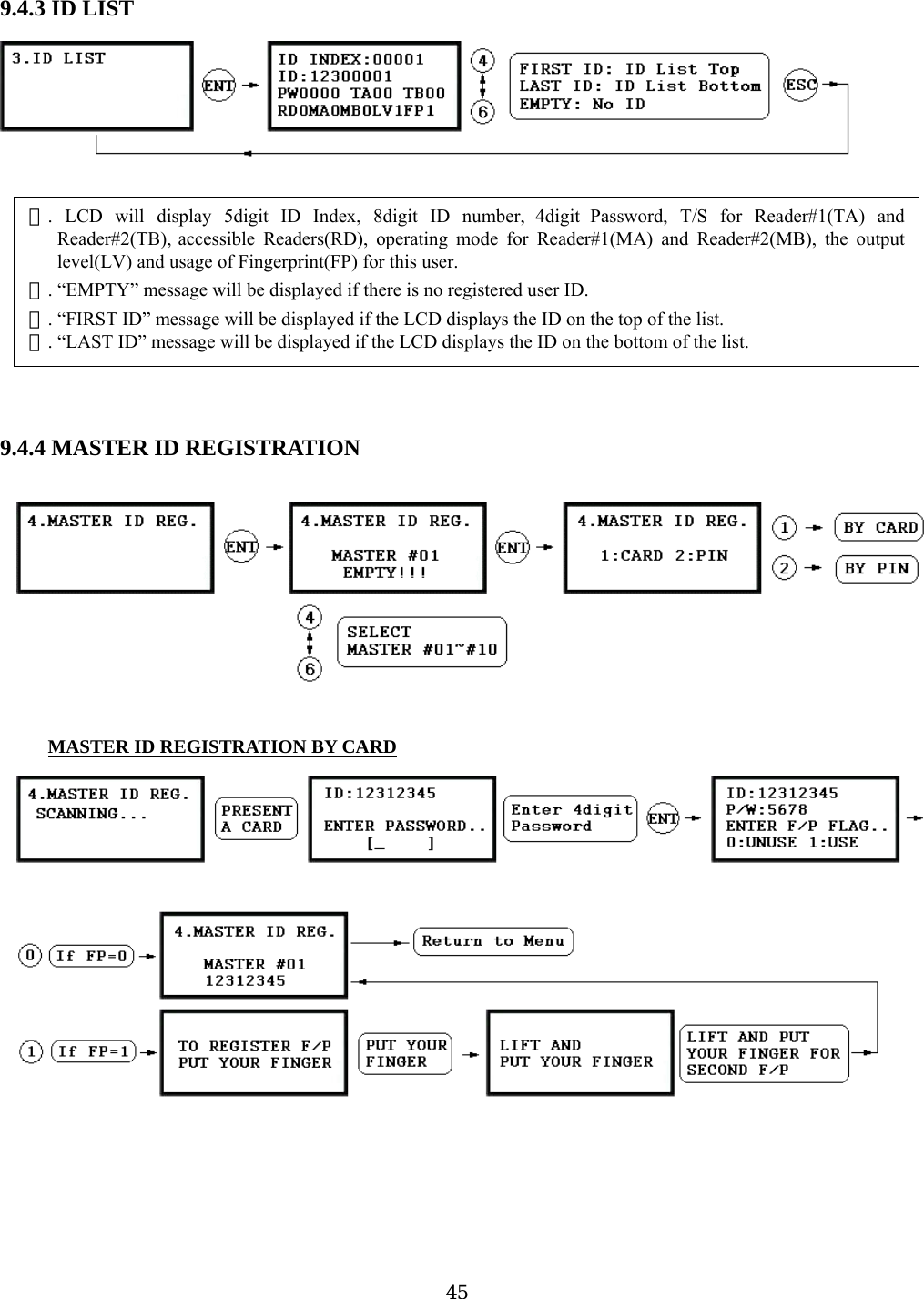
![7. MA: MA is the Reader#1 (Built-in Reader) Operating Mode for the cardholder. If you put ‘1’ for MA, Reader#1 is always operating on RF Only Mode. ‘0’ – System Operating Mode [F2 SETUP MENU] [READER#1 MODE] ‘1’ – ID Only Mode ‘2’ – ID + Finger Mode ‘3’ – ID + Password + Finger Mode 8. MB: MB is the Reader#2 (Exit Reader) Operating Mode for the cardholder. If you put ‘1’ for MB, Reader#2 is always operating on RF Only Mode. ‘0’ – System Operating Mode [F2 SETUP MENU] [READER#2 MODE] ‘1’ – ID Only Mode ‘2’ – ID + Password Mode operating time can be set for each user. o setup Output operating time for each level, refer to the Output Setting on the [F7 SETUP MENU]. ‘2’ – Level #2 9.4.2 ID DELETION 9. LV: LV is the Output Operating Level for the cardholder. OutputT ‘0’ or ‘1’ – Level #1 ‘3’ – Level #3 ‘4’ – Level #4 10. FP: FP is the Fingerprint Usage Flag (1 digit). You can assign the user who uses fingerprint or not. ‘0’ – User without Fingerprint ‘1’ – User with Fingerprint . ☞Registered ID will be deleted in the controller by presenting the card or input the ID number from the keypad.Present the card to be deleted. The ID number will appear on the LCD. If you don’t have the card, input 8digitIDDELETED”D number and <ENT> key from the keypad. If the ID number is found, the ID will be deleted and display “ID. If the ID number is not found, the display will show “ UNREGISTERED ID”. You may repeat IDELETION many times. 44](https://usermanual.wiki/ID-Teck-Co/GE314/User-Guide-570550-Page-44.png)
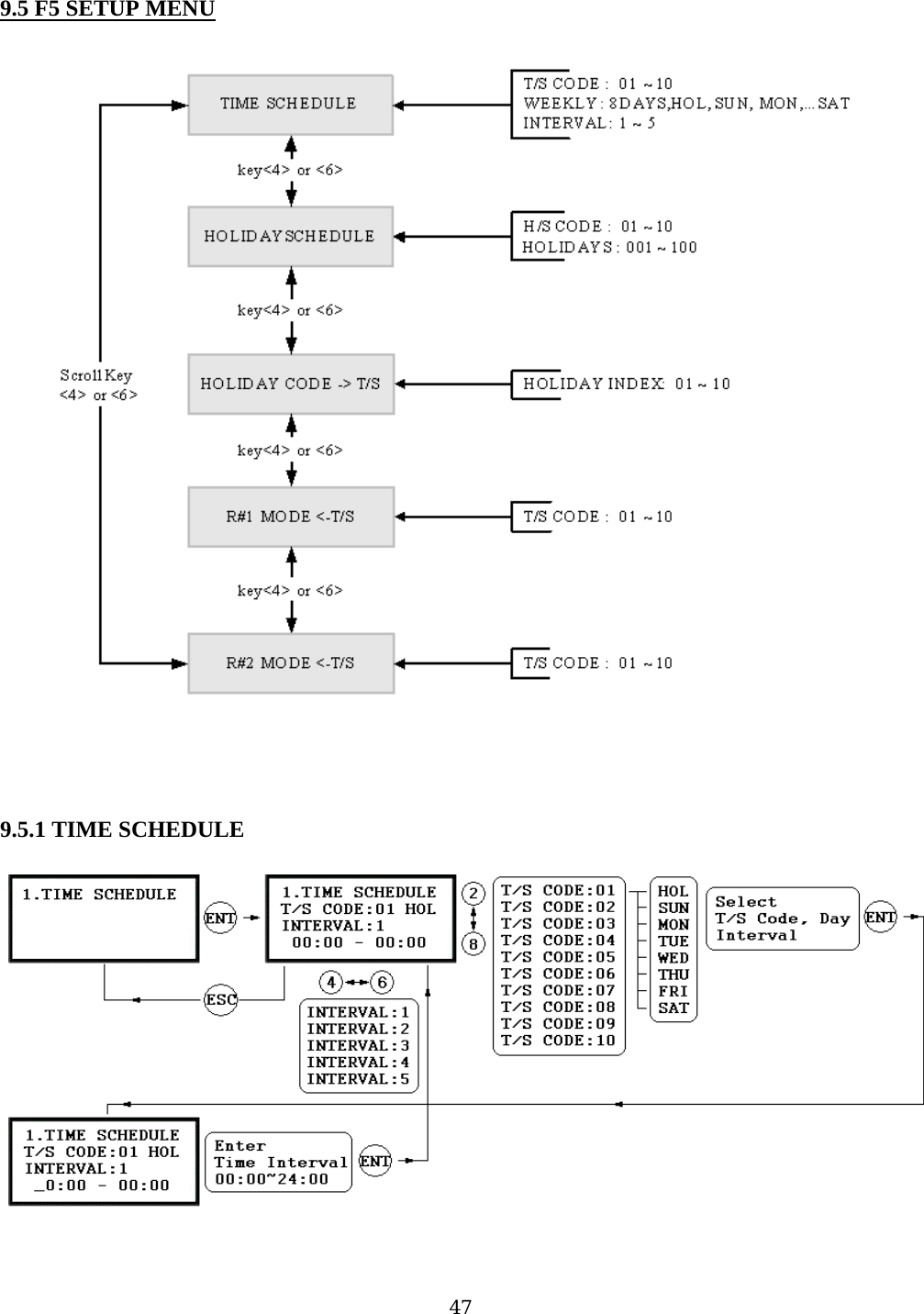
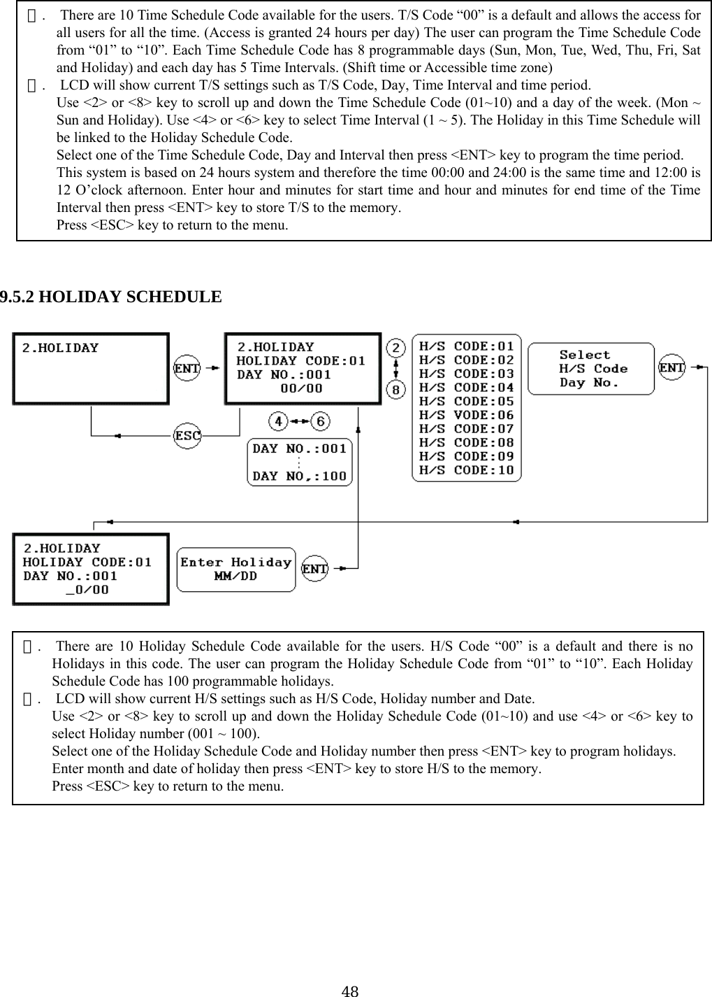
![9. .5.5 R ULE READER#2 MODE TIME SCHEDULE setting is the same as 9.5.4 READER#1 MODE T/S setting. 5.3 HOLIDAY CODE oliday Code is to link the Holiday Schedule to the Time Schedule. T/S has 5 Time Intervals for holidays andth ay Schedule. Default Holiday Schedule Code is‘ o T/S. Use <4> or <6> key to scroll up and down the T/S Code (01~10) and press <ENT> key to enter 2digit Holidais Time Intervals are only applied to the dates of this Holid00’ which means no holidays are applied t 9.5.4 READER#1 MODE TIME SCHEDULE EADER#2 MODE TIME SCHEDPress <ESC> key to return to the menu. . There are 3 system operating mode, ☞ID Only Mode, ID + Finger(Password) Mode and ID + PW + Finger ode. ou can select one of the system operating mode frhowever, you want to apply different operating mode ‘2’ – RF + Finger Mode ‘3’ – RF + PW + Finger Mode ☞. HySchedule Code and press <ENT> key to store Holiday Index to the memory. Press <ESC> key to return to the menu.☞. There are 3 system operating mode, RF Only Mode, RF+F/P Mode and RF+PW+F/P Mode. You can setup oneof the system operating mode from [F2 SETUP MODE]->[R1 MODE SETTING] menu. However, you wantto apply different operating mode for a certain Time Interval for all users. For example, you want to access thedoor by just presenting the card for the time from 09:00 to 17:00 and you want to use Fingerprint verificationfor the rest of the time. In this case, setup [R1 MODE SETTING] to RF+F/P Mode which is for the systemoperating mode and program “01” T/S Code which includes a Time Interval 09:00-17:00 then link “01” T/SCode to this function, R1 MODE T/S setting here. To link a T/S Code (01~10) to Reader#1 Mode, press <ENT> key. Enter 2digit T/S Code and press <ENT>key to store T/S Code to R1 MODE to the memory. M Y om [F2 SETUP MENU]->[READER#1 MODE SETTING] 9 49](https://usermanual.wiki/ID-Teck-Co/GE314/User-Guide-570550-Page-49.png)
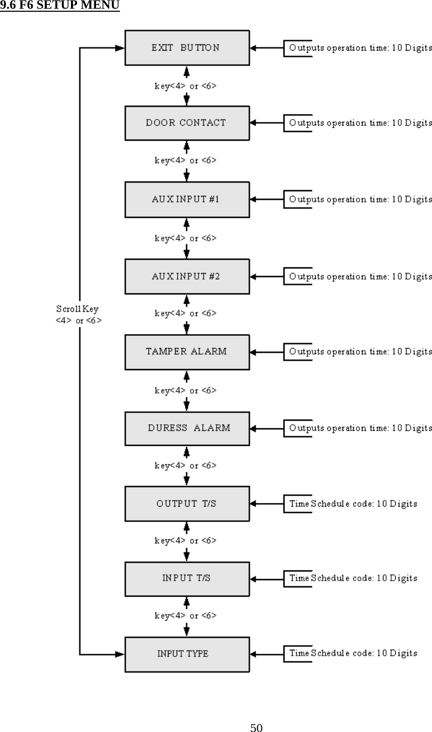
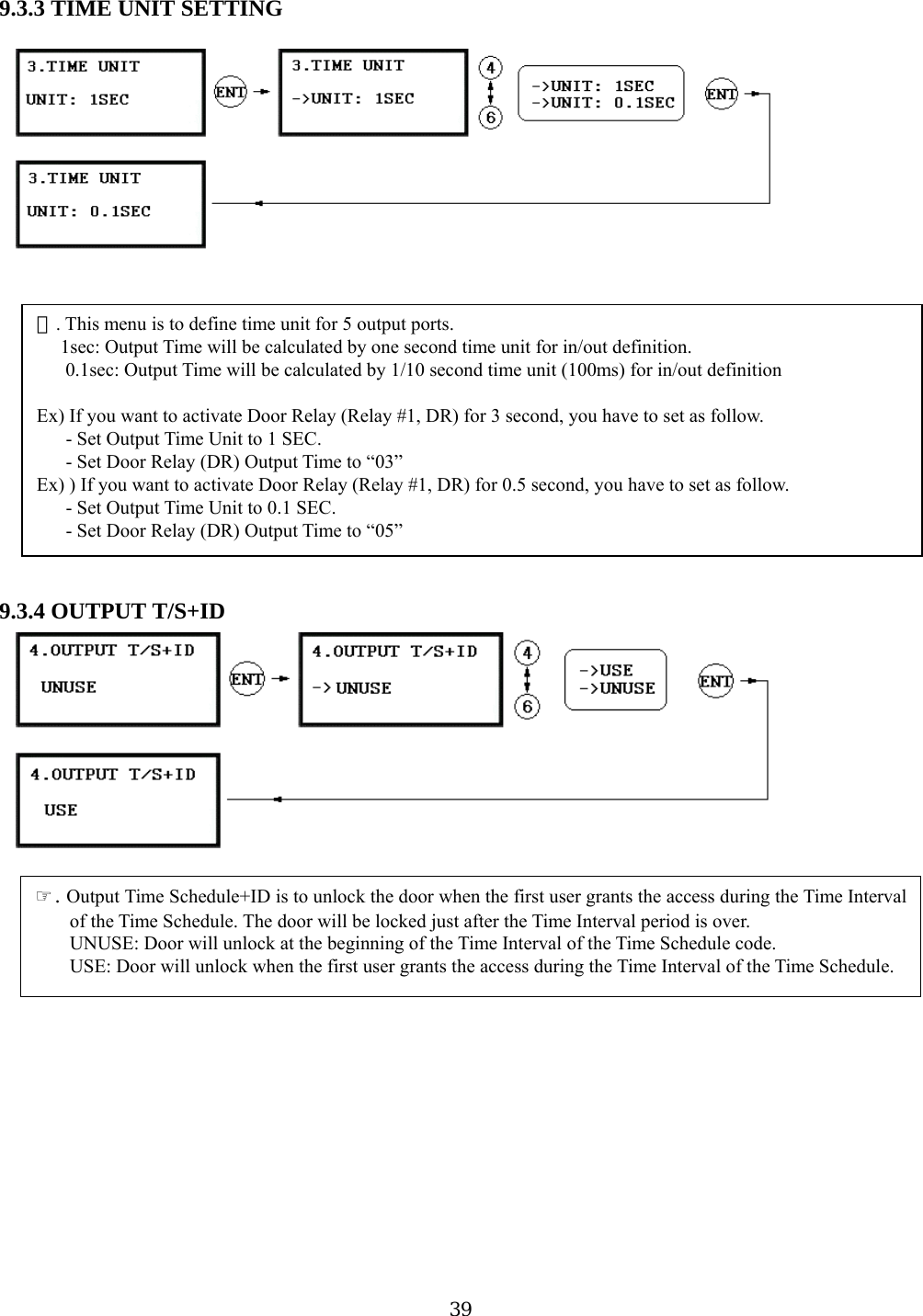
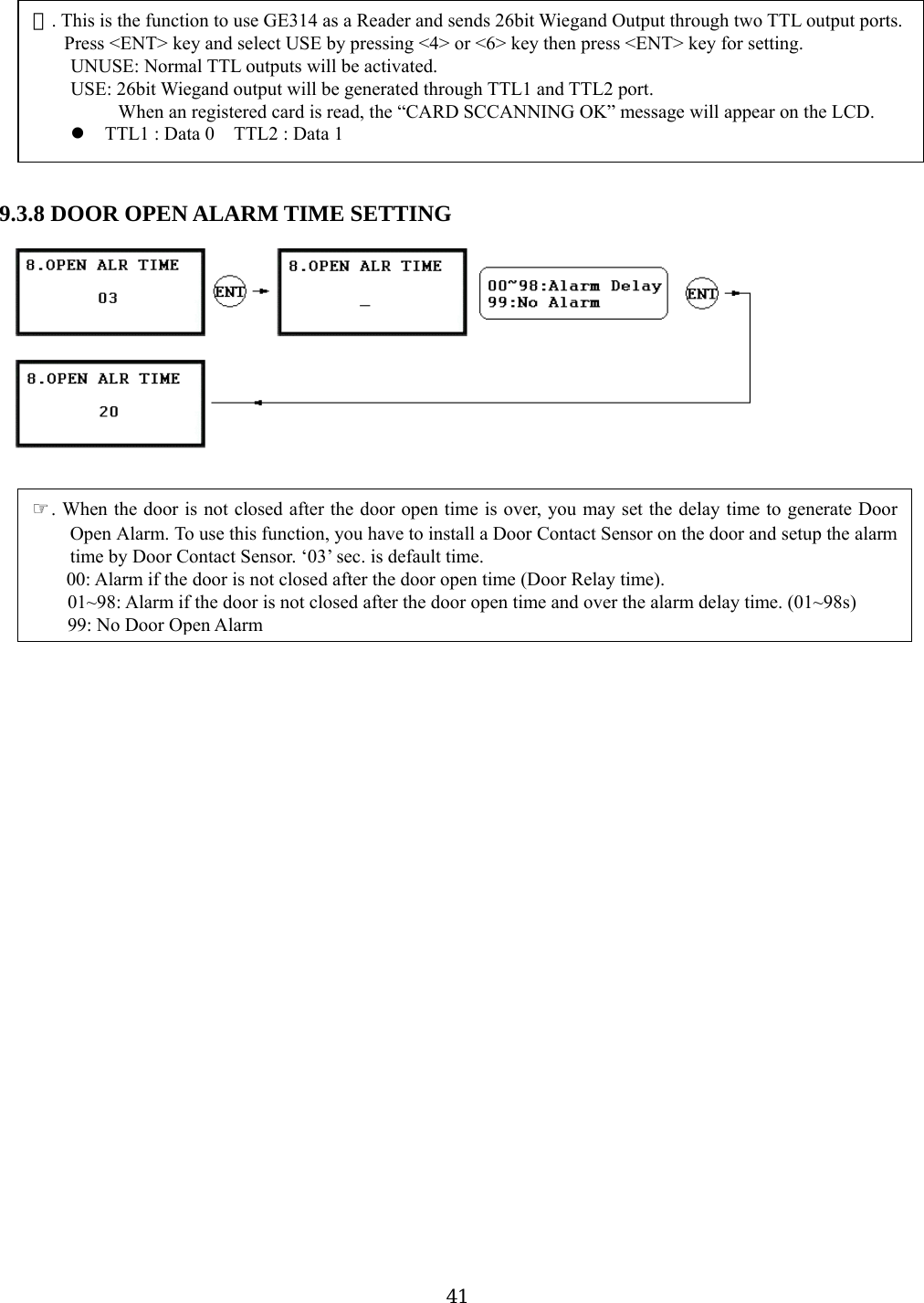
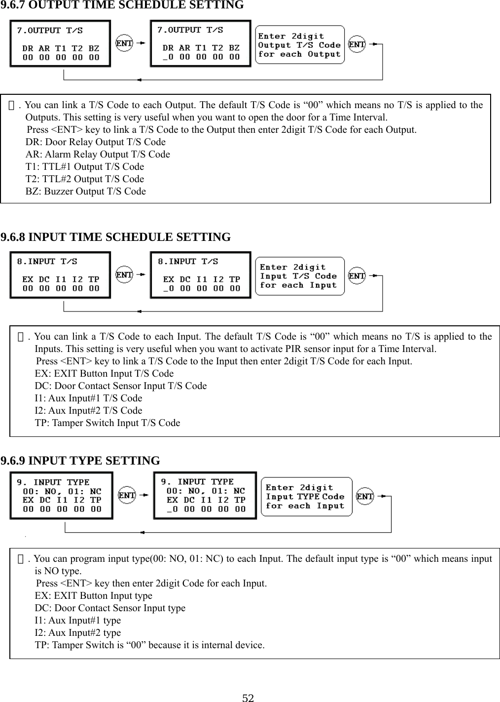
![* Default Output Setting for Input Sources 9.6.1 EXIT BUTTON OUTPUT SETTING 9.6.2 DOOR CONTACT OUTPUT SETTING 9.6.3 AUX INPUT#1 OUTPUT SETTING 9.6.4 AUX INPUT#2 OUTPUT SETTING 9.6.5 TAMPER ALARM OUTPUT SETTING 9.6.6 DURESS ALARM OUTPUT SETTING Output Time setting for above Input Sources are the same as 9.6.1 Exit Button Output setting. OUTPUT Door Relay (DR) Alarm Relay (AR) TTL#1(T1) TTL#2 (T2) Buzzer(BZ) [1] EXIT BUTTON 03 00 00 00 00 [2] DOOR CONTACT 00 99 00 00 00 [3] AUX Input #1 00 00 00 00 00 [4] AUX Input #2 00 00 00 00 00 [5] TAMPER ALARM 00 99 99 99 99 [6] DURESS ALARM 00 00 00 00 00 [7] OUTPUT TIME SCHEDULE 00 00 00 00 00 [8] INPUT TIME SCHEDULE 00 00 00 00 00 [9] INPUT TYPE 00 00 00 00 00 . You can program ☞OUTPUT activating time when the EXIT button pressed. The value put here is value xsecond when the Time Unit set to 1 second and value/10 second when the Time Unit set to 0.1 sec. You can set the time from 00 to 98 seconds (0.0 to 9.8 seconds if Time Unit set to 0.1 sec.) and if you put thevalue “99”, the Output will activate forever until you reset the Output. Press <4> or <6> key to select Input Sources then press <ENT> key to program the Output time. DR: Door Relay Output AR: Alarm Relay Output T1: TTL#1 Output T2: TTL#2 Output BZ: Buzzer Output 51](https://usermanual.wiki/ID-Teck-Co/GE314/User-Guide-570550-Page-51.png)
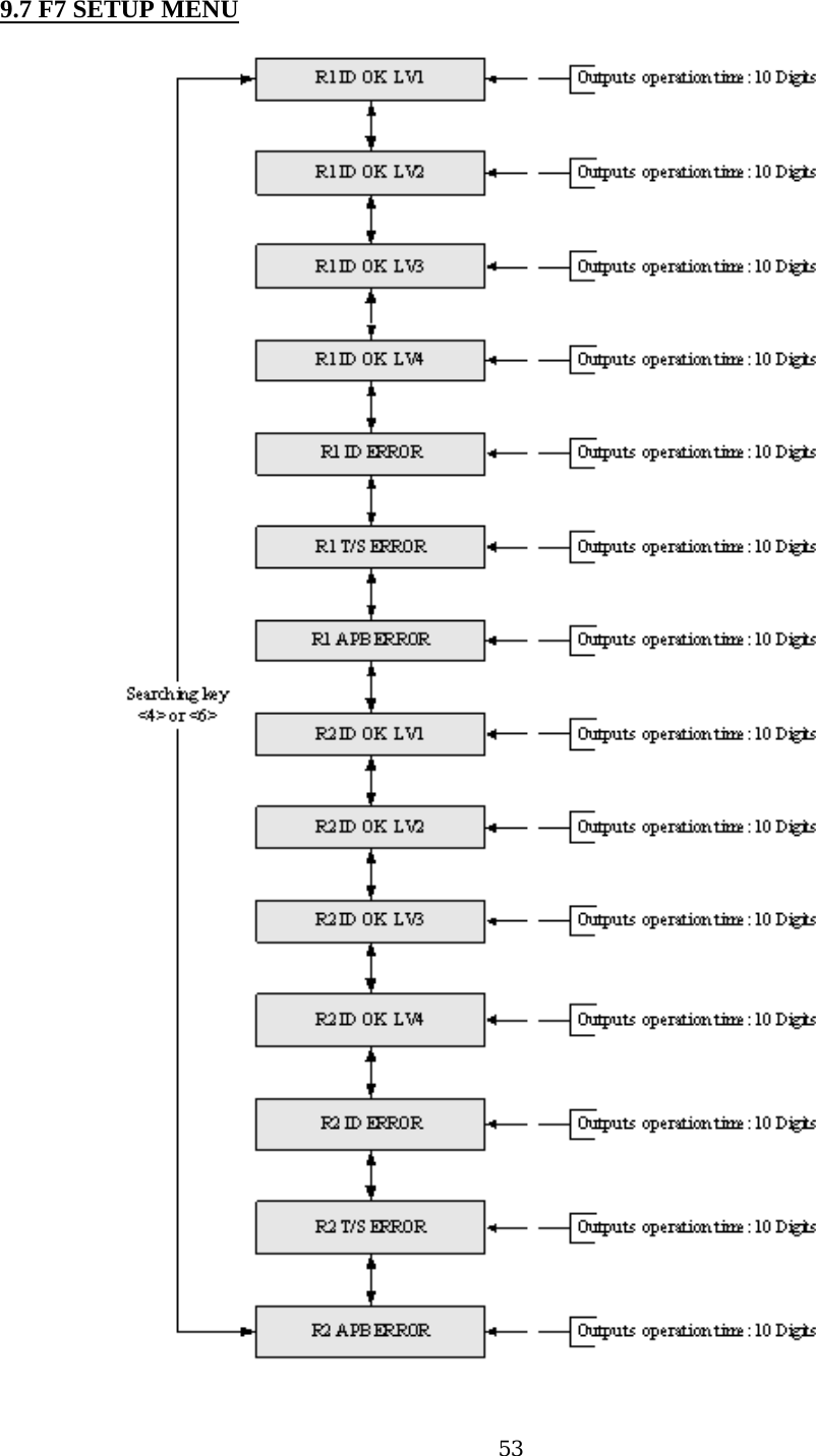
![* Default Output Setting for Input Circumstance 9.7.1 OUTPUT SETTING FOR READER#1 ID OK LEVEL 1 Output Time setting from 9.7.2 to 9.7.14 is the same as 9.7.1 RD1 ID OK LV1 Output setting. OUTPUT Door Relay (DR) Alarm Relay (AR) TTL#1(T1) TTL#2 (T2) Buzzer(BZ) [1] Reader#1 ID OK LV1 03 00 00 00 00 [2] Reader#1 ID OK LV2 05 00 00 00 00 [3] Reader#1 ID OK LV3 05 00 00 00 00 [4] Reader#1 ID OK LV4 05 00 00 00 00 [5] Reader#1 ID Error 00 03 00 00 00 [6] Reader#1 T/S Error 00 03 00 00 00 [7] Reader#1 APB Error 00 03 00 00 00 [8] Reader#2 ID OK LV1 03 00 00 00 00 [9] Reader#2 ID OK LV2 05 00 00 00 00 [10] Reader#2 ID OK LV3 05 00 00 00 00 [11] Reader#2 ID OK LV4 05 00 00 00 00 [12] Reader#2 ID Error 00 03 00 00 00 [13] Reader#2 T/S Error 00 03 00 00 00 [14] Reader#2 APB Error 00 03 00 00 00 . You can program ☞OUTPUT activating time when the user ID is granted the access from the Reader#1. Thevalue put here is value x second when the Time Unit set to 1 second and value/10 second when the Time Unitset to 0.1 sec. This Output Time is applied for the users registered with Level#1 output. You can set the time from 00 to 98 seconds (0.0 to 9.8 seconds if Time Unit set to 0.1 sec.) and if you put thevalue “99”, the Output will activate forever until you reset the Output. Press <4> or <6> key to select Input Sources then press <ENT> key to program the Output time. DR: Door Relay Output Time AR: Alarm Relay Output Time T1: TTL#1 Output Time T2: TTL#2 Output Time BZ: Buzzer Output Time 54](https://usermanual.wiki/ID-Teck-Co/GE314/User-Guide-570550-Page-54.png)
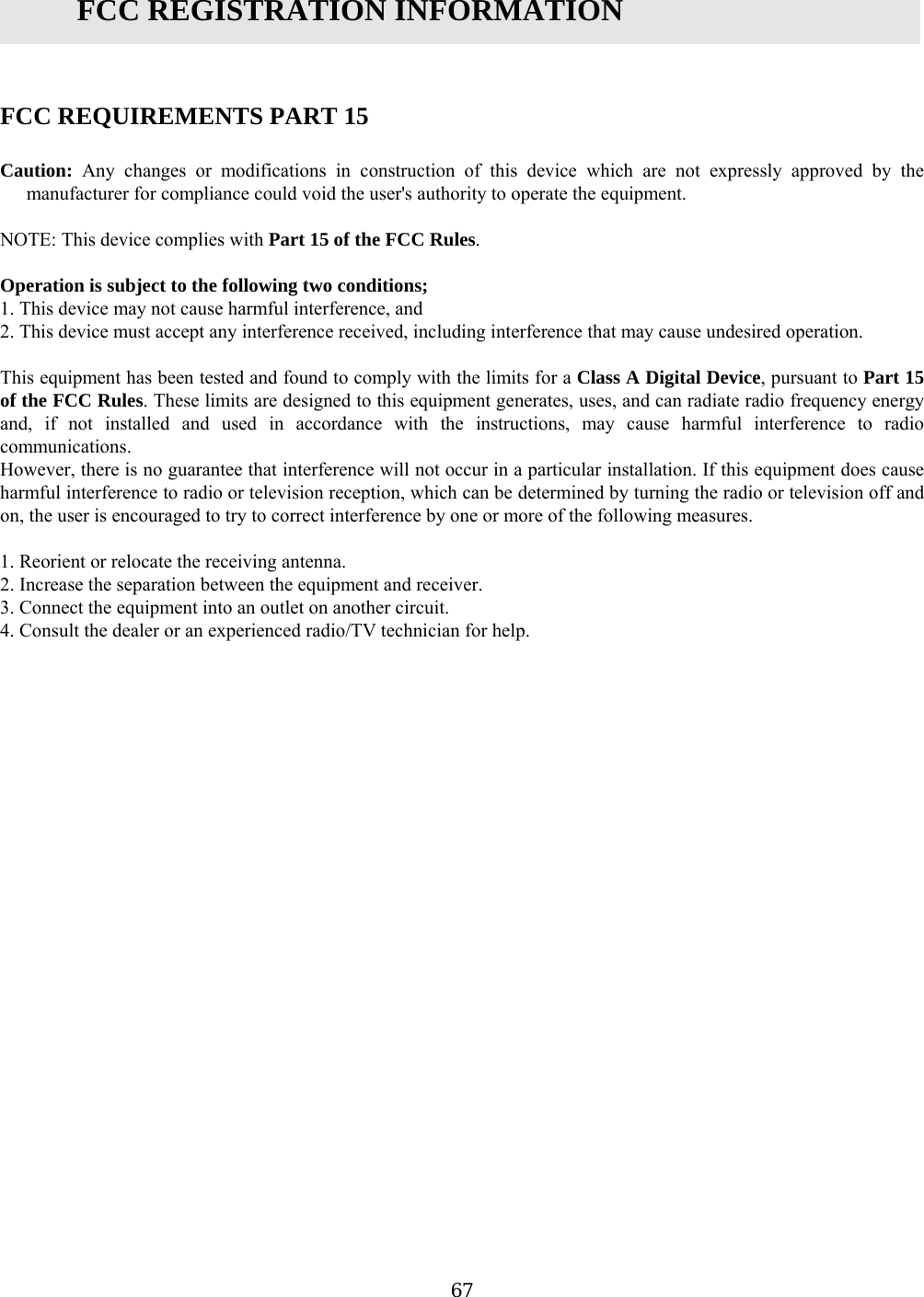
![APPENDIX A. THE RELATION BETWEEN INPUT AND OUTPUT (DEFAULT) * Default Output Setting for Input Sources * Index No. [1] ~ [6]: The value indicates operation time (second) of each output for the input signal. * Index No. [7]: The value indicates time schedule code (index) that each output operation has to be applied. * Index No. [8]: The value indicates the time schedule code (index) that each input #1(Exit button) ~#5 operation has to be applied. * Index No. [9]: The value indicates the type of each input #1(Exit button) ~#5 operation. The “00” is NO(Normal Open) type. The “01” is NC(Normal Close) type. OUTPUT INPUT Door Relay (DR) Alarm Relay (AR) TTL#1(T1) TTL#2 (T2) Buzzer(BZ) [1] EXIT BUTTON 03 00 00 00 00 2] DOOR CONTACT 00 99 00 [00 00 [3] AUX Input #1 00 00 00 00 00 [4] AUX Input #2 00 00 00 00 00 [5] TAMPER ALARM 00 99 99 99 99 [6] DURESS ALARM 00 00 00 00 00 00 00 00 00 0000 00 00 00 00 [7] OUTPUT TIME SCHEDULE [8] INPUT TIME SCHEDULE [8] INPUT TYPE 0 00 00 00 00 0 61](https://usermanual.wiki/ID-Teck-Co/GE314/User-Guide-570550-Page-61.png)
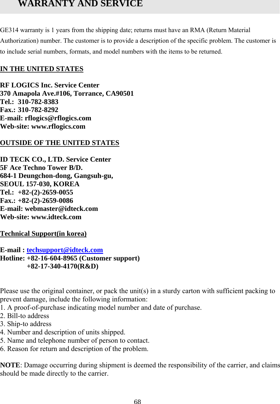
![* Default Output Setting for Input Circumstance 14]: * Index No. [1] ~ [The value indicates operation time (second) of each output for the input signal. OUTPUT INPUT Relay Relay (T1) Door (DR) Alarm (AR) TTL#1 TTL#2 (T2) Buzzer(BZ) [1] Reader#1 ID OK LV1 03 00 00 00 00 [2] Reader#1 ID OK LV2 05 00 05 00 05 00 [5] Reader#1 ID Error 00 03 00 00 00 [6] Reader#1 T/S Error 00 03 00 00 00 [7] Reader#1 APB Error 00 03 00 00 00 [8] Reader#2 ID OK LV1 03 00 00 00 00 [9] Reader#2 ID OK LV2 05 00 00 00 00 [10] Reader#2 ID OK LV3 05 00 00 00 00 [11] Reader#2 ID OK LV4 05 00 00 00 00 [12] Reader#2 ID Error 00 03 00 00 00 [13] Reader#2 T/S Error 00 03 00 00 00 00 00 00 [3] Reader#1 ID OK LV3 00 00 00 [4] Reader#1 ID OK LV4 00 00 00 [1 00 03 00 00 00 4] Reader#2 APB Error 62](https://usermanual.wiki/ID-Teck-Co/GE314/User-Guide-570550-Page-62.png)
![B ☞ A ed after batch-downloading IDs from PC. . TROUBLE SHOOTING valid card became unregisterause Wrong procedure during pon ct. tive of evice. tion 1. Check BAT connection S/You have to short the itialize b C download or a com ent defeSolution 1. The card ID might be registered only to the controller and not registered in the PC. During the process 314 first erase the ID memory of the unit, therefore if the IDs from the PC didn’2. Check whether the card ID is registered in the PC. 3. If not, please register the number and try downloading again. 4. If the trouble remains after the procedure above, contact a designated service center. of downloading IDs, GEt contain the card ID, this can happen. ☞ It doesn’t enter the Setup Mode after entering the Master ID “00000000”. Cause The Master ID might have been changed or components are defective. Solution 1. Try changing the Master ID through the application S/W (It’ll be changed to “00000000”). 2. When it is not feasible, initialize the unit as following: After the all installation and connections are completed, press and hold the Initialize button and put the power (+12V DC) to GE314. The LCD will first display “Initialize OK? 0:No 1:Yes”. Press <1> key if you want to initialize the system. After all Initialization process is completed, the system is operating on normal mode and the LCD displays “GE Security, GE314 [F1], Date Time”. 3. If the trouble remains after the procedure above, contact a designated service center. ☞ When the power off and on after the time setting, the LCD displays “00/00 00:00:01”. Cause Of that user mistake, or the system is defec the dSolu W. S/W, and system in efore system installation. Figure: SWITCH SETTING Figure: SWITCH LOCATION 2. If the trouble remains after checking the above, contact a designated service center. 63](https://usermanual.wiki/ID-Teck-Co/GE314/User-Guide-570550-Page-63.png)
![☞ No problem with accessing by card, but cannot access with the PIN input. Cause An error in Setup or possible component defect. Solution 1. Check whether a beep sound is generated when you press a key. When a beep sound is generated, the problem may be an error in setup. Proceed like followings: 000” default) to enter the Setup mode. - [LANGUAGE] will appear on the LCD, then use the key <6> to choose [RD1_PIN_INPUT] and SE’ as wanted. 2. When th sound or already enabled Key-in functions, contact a designated service center. - Enter the Master ID (“00000- Press <F2> key. select ‘Uere is no beepime out erroup mode, it is programmed to do so when there is no key-in or reading card within 60 ☞ The Setup mode suddenly goes back to the Normal operating mode. Cause T r Solution In the Set seconds. ☞ Keeps making buzzer sound: “beep~ beep ~ beep” or “beeeeeeeep~~~~”. olution 1. Check the door status. It occurs in case that the door is oopen time. Check the door contact sensor type: it should be NO type. Check in [7. OUTPUT T/S] of F6, the ten Tischedule code is set between 01 up to 10 and if the pIf it is set to unintended value, change it to “00” ( Programmab4. Check in Tamper switch of GE314. Cause Error in Installation, Door status or Internal circuits. Spened over 3sec(Default) after the proper door 2.3. me schedule code (01~10) value of output T/S. If the time resent time is included in the schedule. le via PC software) 5. If the trouble remains after checking the above, contact a designated service center. 64](https://usermanual.wiki/ID-Teck-Co/GE314/User-Guide-570550-Page-64.png)