ID Teck Co GE314 Fingerprint Access Controller User Manual 7
ID-Teck Co Ltd Fingerprint Access Controller 7
Users Manual
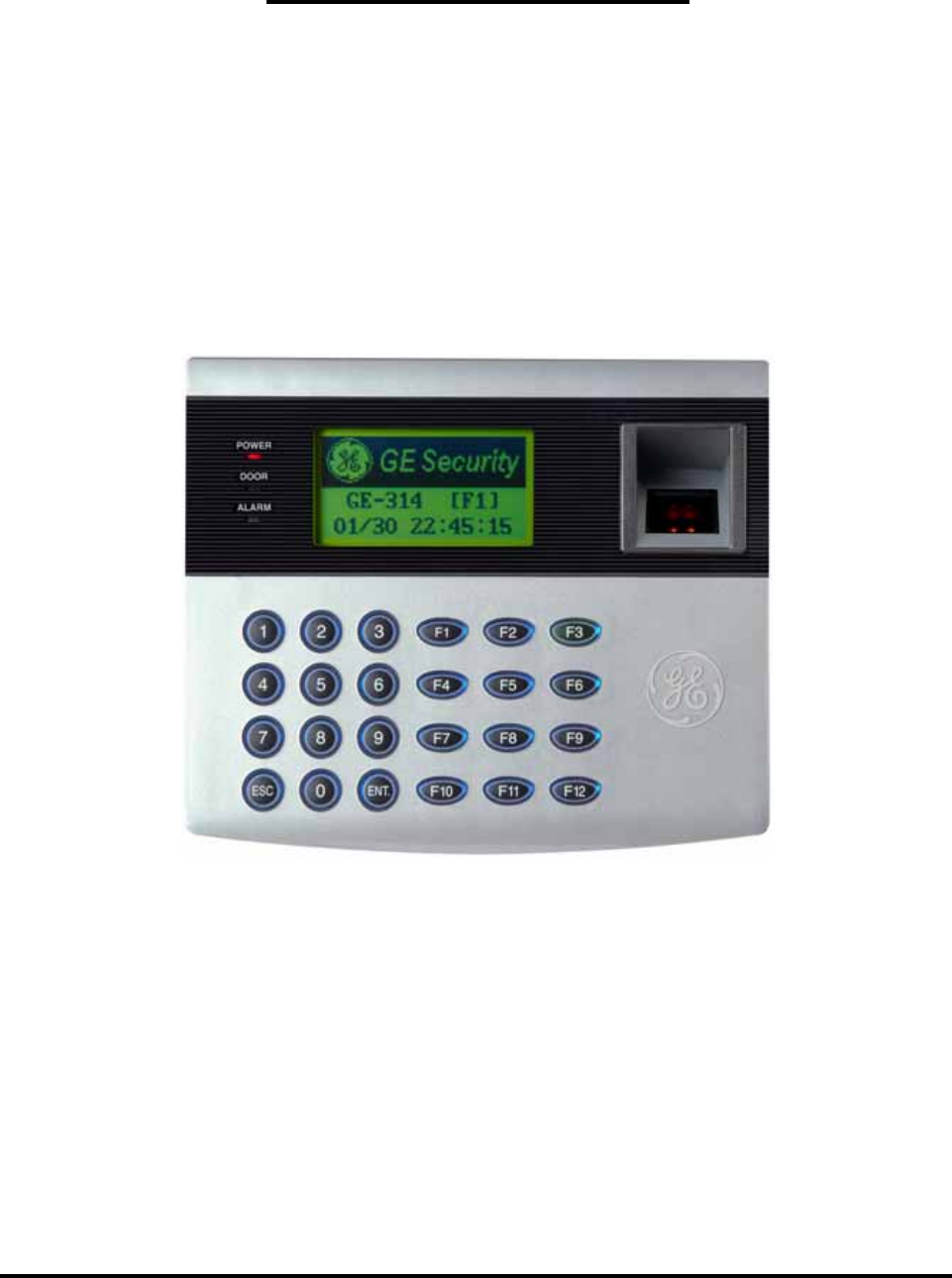
OPERATING MANUAL
FINGERPRINT ACCESS CONTROLLER
MODEL: GE314

Table of Contents
1. IMPORTANT SAFTY INSTRUCTIONS Page 4
2. INTRODUCTION Page 6
2.1 IDENTIFYING SUPPLIED PARTS Page 6
2.2 INTRODUCTION Page 6
2.3 FEATURES Page 6
2.4 SPECIFICATIONS Page 7
3. PRODUCT OVERVIEW Page 8
3.1 FUNCTIONS Page 8
3.2 PRODUCT EXPLANATION Page10
3.2.1 FRONT PANEL DESCRIPTION Page10
3.2.2 CONNECTOR LAYOUT Page11
3.2.3 WIRE COLOR TABLE OF THE GE314 Page11
4. INSTALLATION TIPS & CHECK POINT Page 12
4.1 CHECK POINT BEFORE THE INSTALLATION Page 12
4.1.1 CABLE SELECTION Page 12
4.1.2 CABLE SELECTION TABLE Page 13
4.2 CHECK POINT DURING THE INSTALLATION Page 13
4.2.1 TERMINATION RESISTOR Page 13
4.2.2 HOW TO CONNECT TERMINATION RESISTOR Page 14
4.2.3 GROUND SYSTEM Page 14
4.2.4 REVERSE DIODE CONNECTION Page 15
5. INSTALLATION Page 15
5.1 WALL MOUNT DRAWING Page 15
5.2 BACKUP BATTERY SWITCH Page 16
5.3 SYSTEM INITIALIZATION Page 16
5.4 WALL MOUNT INSTALLATION Page 17
6. WIRING Page 17
6.1 POWER CONNECTION Page 17
6.2 INPUT CONNECTION Page 17
6.3 OUTPUT CONNECTION Page 18
6.4 EXTERNAL READER CONNECTION Page 18
6.5 RS232 PORT CONNECTION Page 19
6.6 RS485 PORT CONNECTION Page 20
6.6.1 RS485 CONNECTION (SINGLE UNIT) Page 20
6.6.2 RS485 CONNECTION (MUTIPLE UNITS) Page 20
6.7 TCP/IP CONNECTION (OPTIONAL) Page 21
2

7. BASIC SETTINGS Page 22
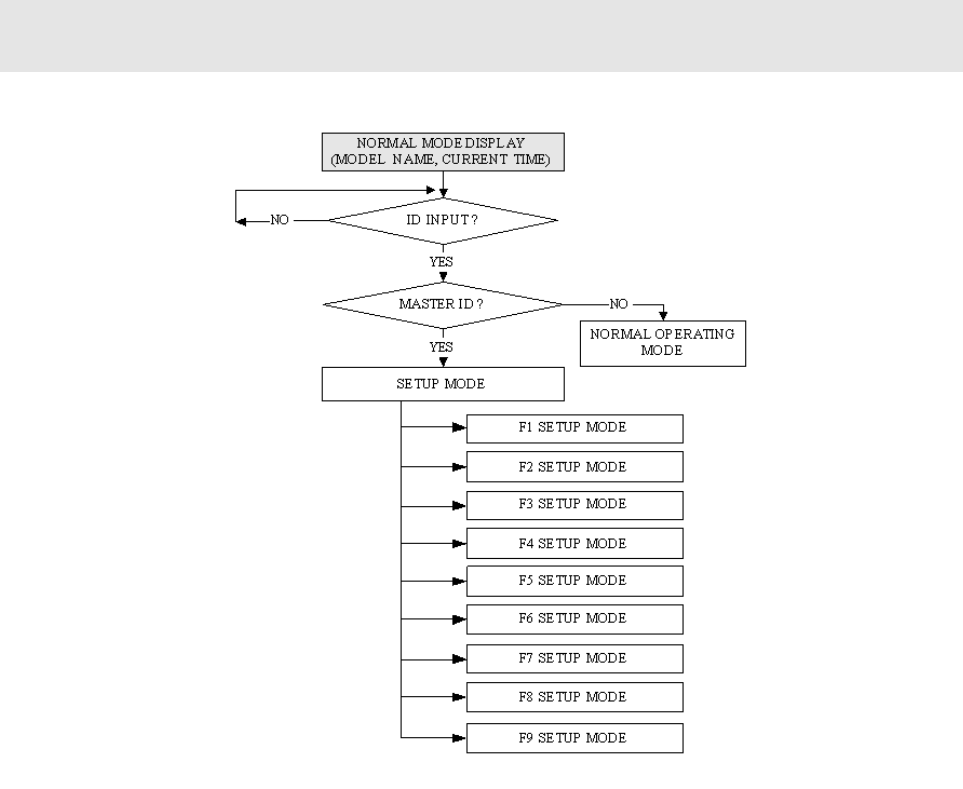
7.1 INITIALIZATION OF GE314 Page 22
7.2 HOW TO ENTER THE SETUP MENU Page 22
7.3 LANGUAGE SETTING Page 23
7.4 DATE/TIME SETTING Page 23
7.5 ID REGISTRATION Page 24
8. OPERATION Page 27
8.1 NORMAL OPERATION Page 27
8.2 DEFAULT SETTING Page 27
9. SETTING CHANGES Page 28
9.1 F1 SETUP MENU Page 29
9.2 F2 SETUP MENU Page 33
9.3 F3 SETUP MENU Page 37
9.4 F4 SETUP MENU Page 42
9.5 F5 SETUP MENU Page 47
9.6 F6 SETUP MENU Page 50
9.7 F7 SETUP MENU Page 53
9.8 F8 SETUP MENU Page 56
9.9 F9 SETUP MENU Page 59
APPENDIX Page 61
A. THE RELATION BETWEEN INPUT
AND OUTPUT (DEFAULT) Page 61
B. TROUBLE SHOOTING Page 63
FCC REGISTRATION INFORMATION Page 67
WARRANTY AND SERVICE Page 68
RMA REQUEST FORM & A/S REQUEST FORM Page 69
3

1. IMPORTANT SAFETY INSTRUCTIONS
To prevent injuries to persons and damages to property, please read all instructions and follow them
whenever you deal with this product.
After reading, please put this instruction manual where it can be easily seen for the system operator.
ON INSTALLATION AND POWER
Use 12V DC power ONLY.
- Connecting to higher than 12V DC may result in a risk of electric shock, fire, or heavy damage of the unit.
Do NOT install this product at places with wet or metallic dust or that can be watered.
- There may be risks of electric shock and fire.
Do NOT install this product near electric motors running.
- The Unit may not operate normally.
Do NOT set this product near heaters or any thing that produces heat.
- There may be a risk of fire.
Be ALWAYS careful not to short-circuit any part of the circuitry with tools like a screwdriver.
- There may be a risk of fire or heavy damage of the unit.
ON MAINTENANCE
Do NOT use any kind of liquid for cleaning.
- There may be a risk of electric shock, fire or heavy damage of the unit. Use air spray, if needed.
Users are cautioned NOT to attempt repair of this product or modify the wirings set by the installer at their own
discretion.
- It may pose the risk of fire, hardware damages, or abnormal operations of the unit.
It is recommended not to use a flammable spray or something else easy flammable near this product.
- There may be the risk of an explosion or fire.
Keep the unit away from any unauthorized people.
- It may cause abnormal operations of the unit.
4

NOTICE
Please contact a designated service center or the outlet at which the product was purchased when
A. Any liquid has been spilt or sprayed onto the product. In this case, cut the power off first.
B. The product seems to be operating abnormally.
C. The unit exhibits a distinct change in performance.
D. The unit has fallen to be broken down or damaged on its case.
* Repairing costs can be charged for troubles caused due to improper handling or negligence of users or the operator.
5
2. INTRODUCTION
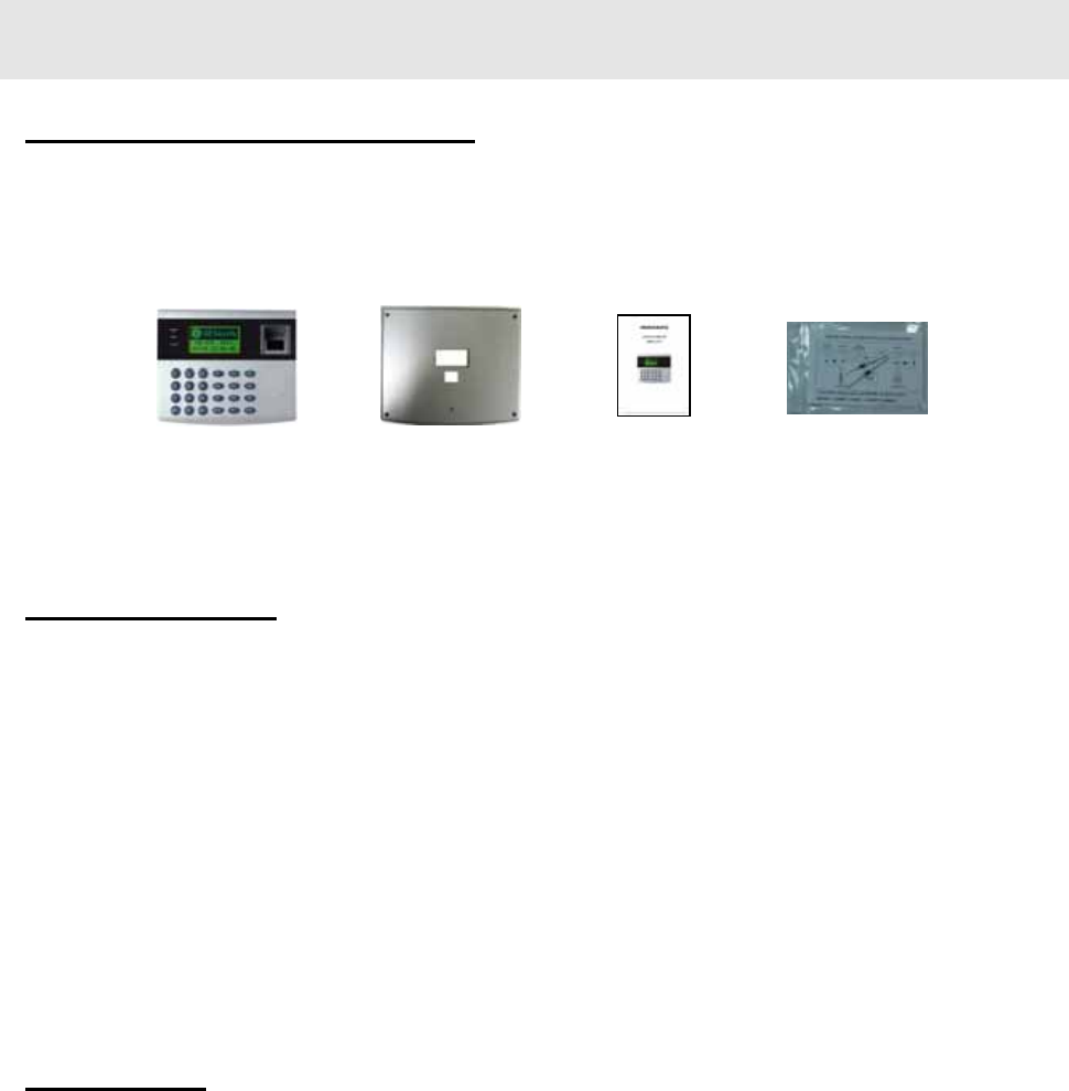
2.1 IDENTIFYING SUPPLIED PARTS
Please unpack and check the contents of the box (Optional accessories, if purchased, may be included in the
package).
Main unit Wall mount Manual Diode
( 1ea ) ( 1ea ) ( 1ea ) ( 2개 )
2.2 INTRODUCTION
The GE314 is ideal to use for Single Door Access Control and Time & Attendance. The GE314 has four input
ports, two Form-C relay outputs, two TTL outputs, RS232/RS485 communication port and optional TCP/IP
communication port to meet various customer requirements. This user-friendly device allows you to register up
to 1,000 Fingerprint Users (Optional 2,000/4,000 Fingerprint Users) and can be stored up to 20,000 event
transactions. All Events can be uploaded and saved to the database of the host PC and the software creates the
report to MS-Excel, HTML and Text files for the Time & Attendance purpose. The GE314 has a built-in
Fingerprint Module, proximity card reader with IDC 26-bit Wiegand format and it has 24 keypads (10 Numeric
keys, 2 Control keys and 12 Function keys) for wide applications. The GE314 allows to accessing the door with
any combination of Fingerprints, Proximity Card/PIN and/or Password. The GE314 has four external input ports
to be connected to an exit button, motion detector, door contact sensor and existing alarm system to prevent
unauthorized access. The GE314 has a door relay to control the door lock and an alarm relay to warn any error.
The graphic LCD display supports 6 different languages so that the unit can be operated anywhere in the world.
All setup menus can be programmed through the front keypads or via Windows-based software program. The
GE314 is a cost effective biometrics system to be used for Standalone or network. Dual tamper switches prevent
unauthorized access.
2.3 FEATURES
Dual function for Access Control and Time & Attendance
8 bit and 16 bit Dual Microprocessors, 32 bit ARM9 Microprocessor for Fingerprint Module
1,000 Fingerprint Users (Optional 2,000/4,000 Fingerprint Users) and 20,000 Event Buffers
Built-in Fingerprint Scanner, Module and Algorithm
Built-in Proximity Reader and External Reader Port for T&A
24 Keypads including 12 Functional Keys
Graphic LCD Display for 6 different Language Support
Standalone or Network Communication via RS232/RS485 (max. 256ch)
Optional TCP/IP Communication, Optional Automatic Touch Sensor (for Identification Mode)
Independent 4 Inputs and 4 Outputs including 2 FORM-C Relay Outputs
Output Time Setting for Individual ID(4 Levels – Longer Output Time for Handicap Person)
Forced Door Open Alarm, Door Lock/Unlock by T/S and/or by registered ID
Anti-pass Back, Duress Alarm Functions
6

Dual Tamper Alarm
10 Time schedules, 8 Days with 5 Individual Time intervals each
10 Holiday Schedules, 100 holidays each
Operating Mode Selectable for Individual ID (Proximity/PIN Only Mode, Fingerprints Only Mode,
Proximity/PIN + Fingerprints Mode, Proximity/PIN + Password + Fingerprints Mode)
Time Schedule Applied to Individual ID, Input Port, Output Port and Reader Mode
Multiple Master ID/Fingerprints Registration
3 LED Indicators and Beeper for the System Status
2.4 SPECIFICATIONS
CPU 8 bit and 16bit Dual Microprocessors, 32bit ARM9 Microprocessor
Memory Program Memory: 2M bit ROM
Data Memory: 4M bit FLASH memory
Fingerprint Module: 1M bytes FLASH memory (Optional 2M/4M bytes)
Fingerprint User
Event Buffer
1,000 Fingerprint Users (Optional 2,000/4,000 Fingerprint Users)
20,000 Event Buffers
Operating Mode Operating mode can be programmed for Individual ID
- Proximity ID/PIN Only Mode
- Fingerprints Only Mode (Up to 500 Users only, Identification Mode)
- Proximity ID/PIN + Fingerprints(Password) Mode
- Proximity ID/PIN + Password + Fingerprints Mode
FAR (False Acceptance Rate) 0.001%
FRR (False Reject Rate) 0.1%
Fingerprint Scanner Optical Scanner, LED Lighting
Resolution of Scanner 500dpi, CMOS CCD, 356 x 292 pixels
1:1 Verification Time < 1 sec.
1:N Identification Time < 3 sec. if ID found (Up to 500 Fingerprints only)
Reader Port 1 Internal and 1 External Reader Port
Read Range Up to 4” (10cm) with IDC170 Clamshell Card
Reader Data Format Standard IDC 26 bit Wiegand Format
8 bit Burst Format for Keypad Reader
Communication port RS232/RS485(up to 256 channels) Address Selectable
9600(Default), 19200, 38400, 57600bps Communication Speed
Input/Output 4 Input Ports, Rating DC12V/ 20mA max.
2 Relay Outputs, DC12V~24V/ FORM-C Relay 2A max.
2 TTL Outputs, DC0 ~5V/ 20mA max.
Keypad 24 keys with Back lighting (Sky Blue)
- 10 Numeric Keys
- 2 Control Keys
- 12 Function Keys
Self Diagnostic Yes
Reset Power On Reset and Watch-dog Timer Reset
Operating Status 3 LED (Red, Green, Yellow) indicators, Beeper
7

Weight 1.62 lbs (735g)
Dimensions 7.56” x 6.42” x 1.97” (192mm x163mm x50mm)
LCD Display Module 128 x 64 dots, 2.85” x 1.56”(72.5mm x 39.5mm) View Area
Power DC 12V±10%, 550mA max.
Operating Environment 32°F ~ 149°F (0°C ~ +45°C), 0 ~ 90% Humidity None Condensing
Storage Environment -40°F ~ 158°F (-40 ~+70℃℃), 0 ~ 90% Humidity None Condensing
Mount Wall Mount or Electrical Gang Box Mount (U.S. and European/Asian)
Color Silver and Dark Gray Color
Optional
TCP/IP Module (Internal)
Connection
IIM7100A Internal Mounting Module for TCP/IP Communication
RJ45 Socket
Automatic Touch Sensor Capacitance Touch Sensor for Identification Mode only
Fingerprint Module 2,000 Fingerprint Module, 4,000 Fingerprint Module
3. PRODUCT OVERVIEW
3.1 FUNCTIONS
Stand-Alone Operation
The GE314 is capable of having 2 readers (1 Door Control). The unit receives card ID numbers from the
proximity readers and determines whether or not to unlock the door. When an input signal is entered, for
example from a Sensor activated or an Exit button pressed, the controller generates and logs an appropriate
response by input signals. All events are stored into the memory buffers and sent to the host computer. The
access controller is a true stand-alone device that, in the event of malfunction, will not affect other units when
used in conjunction with one another.
Operation with Host Computer
All event transactions can be managed via the host computer. The data transmitted from the controller can be
displayed and stored on the host PC.
Keypad
If the GE314 is not connected to a host PC, the integrated keypad and LCD display module can also be used
for the entire programming process.
Input/Output
The GE314 has 4 built-in inputs and 4 outputs (2 relay outputs and 2 TTL outputs) which can be used to
manipulate a wide variety of controls.
8
Time Schedule Setup
You can program 10 time schedules and apply one time schedule to each User. Each time schedule has 8
different time zones from Monday-Sunday (7 time zones) and one holiday. Each time zone has 5 different
time codes so you can program 5 different time codes to each day. You can also program time schedules for
individual inputs and outputs. Note that the time schedule for input is activated time code for input device so
that the input is activated during the time code on this time schedule. Each time schedule is linked to one
holiday schedule and this linked holiday only validates to the holiday time code of the time schedule.
Holiday Schedule Setup
Excepting Sunday, you can program 100 holidays to one holiday schedule. Each holiday schedule is linked to
one time schedule which has a time code for holidays. You can program all holidays to a holiday schedule
and the time code for holidays is programmed to the holiday time zone of time schedule.
Example: A. Holiday schedule 01 linked to time schedule 01,
Holiday schedule 02 linked to time schedule 02
B. Holiday schedule 02 linked to time schedule 01,
Holiday schedule 01 linked to time schedule 03
Forced Door Open Alarm
When the door is opened by force, the door contact sensor will be activated. For this application, you have to
install the door contact sensor and properly set the door contact time and outputs to the alarm devices. The
Forced Door Open Alarm will be generated until the alarm is cleared.
Overtime Door Open Alarm
The Overtime Door Open Alarm will be generated when the door is open continusly, after the door is opened
by corrected process.
The Overtime Door Open Alarm will be generated until the door is closed.
Anti-Pass-Back
By using an additional proximity reader, the Anti-Pass-Back mode can be set. The Anti-pass-back mode
prevents entry or exit when the registered user did not properly followed one entry and one exit by the Anti-
pass-back rule. The same user can not enter twice with the entry card without properly using the exit before.
Duress Alarm
In case of duress, enter the 2 digits Duress Password and press the<ENT> key before the normal access
process. The door can be opened as normal, but the duress alarm is also generated at the same time. The
duress alarm output will be activated to the TTL output and an alarm event will be sent to the host PC.
9
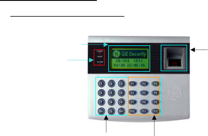
3.2 PRODUCT EXPLANATION
3.2.1 FRONT PANEL DESCRIPTION
LCD
System Operation
Status LED
Fingerprint
Scanner
24 key pad Function key
Figure: Description of GE314 Front Panel
LCD Module:
LCD module display GE314 status.
System Operation Status LED:
When the power is applied to GE314, the red LED is turned on.
When the Relay #1 is operated, the green LED is turned on.
When the Relay #2 is operated, the yellow LED is turned on.
24 key pad:
You can operate GE314 manually by using the key pad.
Function key:
The GE314 has 12 Function keys ([F1] ~ [F12]).
10
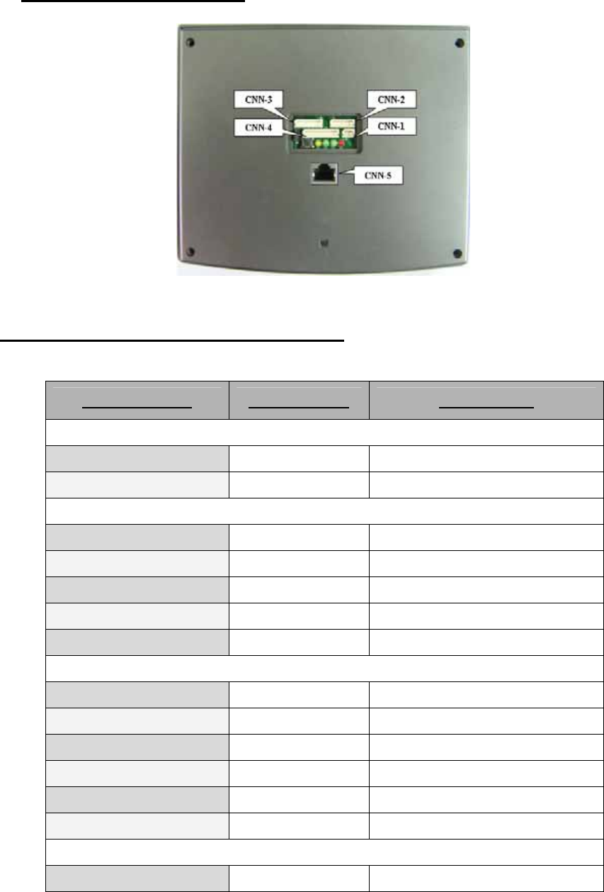
3.2.2 CONNECTOR LAYOUT
Figure: Connector Layout
3.2.3 WIRE COLOR TABLE OF THE GE314
I/O PORT NAME SIGNAL NAME WIRE COLOR
CNN-1: POWER
Main Power (+12V) +12V Red wire
Power Ground 0V Black wire
CNN-2:COMMUNICATION
RS485-RTX(+) RS485-A(+) Gray wire
RS485-RTX(-) RS485-B(-) Blue wire
RS232-TX TXD Red wire with white stripe
RS232-RX RXD Black wire with white stripe
RS232-GND GND Black wire
CNN-3: INPUT/OUTPUT
TTL OUTPUT #1 TTL#1, WD0 Brown wire
TTL OUTPUT #2 TTL#2, WD1 Yellow wire
Aux Input #1 IN#1 Pink wire
Aux Input #2 IN#2 Cyan wire
Wiegand DATA 0 DATA-0 Green wire
Wiegand DATA 1 DATA-1 White wire
CNN-4: INPUT/OUTPUT
Door RELAY(NC) NC(1) Gray wire with white stripe
11
Door RELAY(COM) COM(1) Green wire with white stripe
Door RELAY(NO) NO(1) White wire with red stripe
Alarm RELAY(NC) NC(2) Yellow wire with red stripe
Alarm RELAY(COM) COM(2) Brown wire with white stripe
Alarm RELAY(NO) NO(2) Blue wire with white stripe
Exit Button EXIT Orange wire
Door Sensor CONTACT Purple wire
CNN-5: TCP/IP RJ45 CONNECTOR
4. INSTALLATION TIPS & CHECK POINT
4.1 CHECK POINT BEFORE THE INSTALLATION
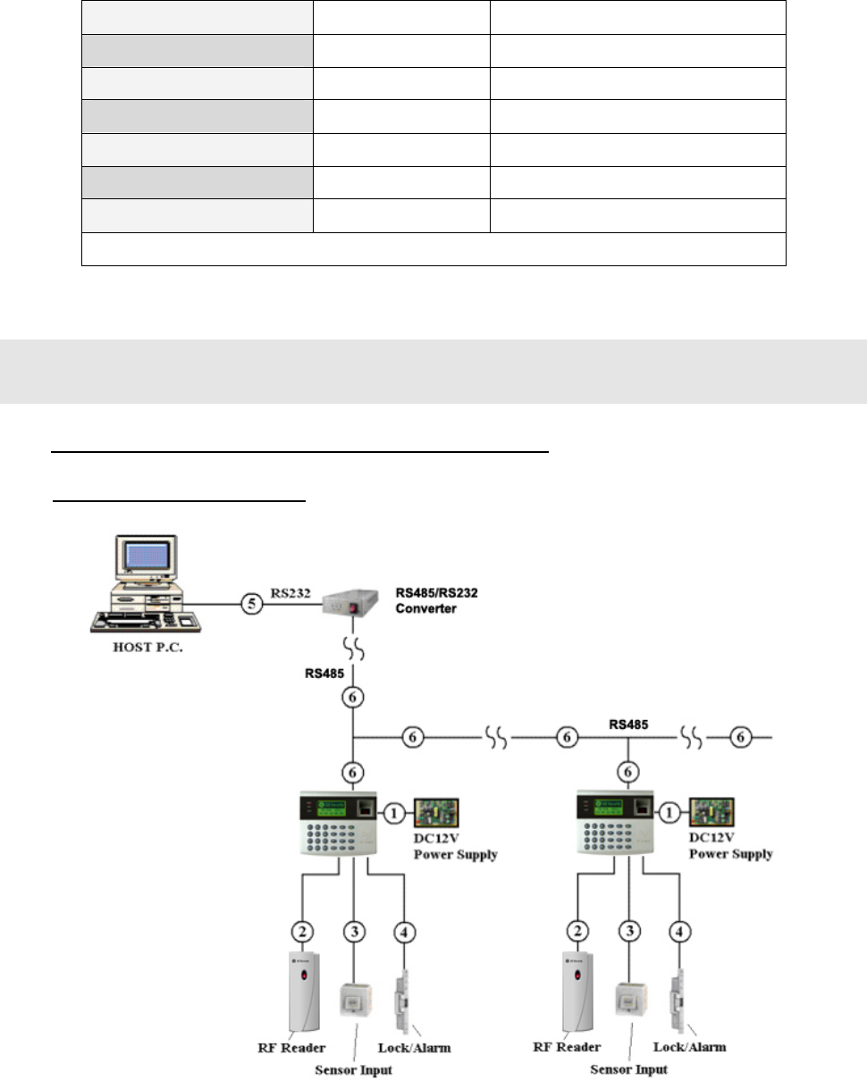
4.1.1 CABLE SELECTION
Figure: System Installation Layout
12

4.1.2 CABLE SELECTION TABLE
Reference Description Cable Specification Maximum Distance
① GE314 Power (DC12V)
DC Power -> GE314
Belden #9409, 18 AWG
2 conductor, unshielded
Belden #9512, 22 AWG
4 conductor, shielded
②+Reader (Power and Data)
Exit Reader -> GE616 Belden #9514, 22 AWG
8 conductor, shielded
Belden #9512, 22 AWG
4 conductor, shielded
③
Door Contact
Exit Button
Sensor Input
Input -> GE314
Belden #9514, 22 AWG
8 conductor, shielded
④ Door Lock, Alarm Device
Lock (Alarm) -> GE314
Belden #9409, 18AWG
2 conductor, unshielded
⑤ RS232 Cable
Converter -> Host P.C.
Belden #9829, 24 AWG
2-twisted pair, shielded
⑥
RS485 Cable
GE314 -> GE314
GE314 -> Converter
Belden #9829, 24 AWG
2-twisted pair, shielded
+ : Need thicker wire if you connect the reader with high current consumption.
4.2 CHECK POINT DURING THE INSTALLATION
4.2.1 TERMINATION RESISTOR
Termination resistors are used to match impedance of the network to the impedance of the transmission line
being used. When impedance is mismatched, the transmitted signal is not completely absorbed by the receiver
and a portion of signal is reflected back into the transmission line. The decision whether or not to use termination
resistors should be based on the cable length and data rate used by the communication system. For example, if
you use 9,600 baud rate and 1,200m length of cable, the propagation velocity of cable is 0.66 x speed of light
(This value is specified by the cable manufacturer), if we assume the reflections will damp out in three round trip
up and down the cable length, the transmitted signal will stabilize 18.6us after the leading edge of a bit. Since the
data bit is captured in the middle of the bit which is approximately 52us after the leading edge of a bit. The
reflection stabilizing time 18.6us is much before the center of the bit therefore the termination resistors are not
required. However, if you install the cable to maximum length, the impedance of cable and network is
mismatched and the transmitted signal is overlapped by the reflected signal. In this case, it is recommended to
add termination resistors to the end of the receiver lines. A 120Ω resistor can be used for termination resistor in
parallel between the receiver lines “A” and “B” for 2 wires RS485 system. A termination resistor of less than
90Ω should not be used and no more than 2 terminations should be used in one networking system.
13
4.2.2 HOW TO CONNECT TERMINATION RESISTORS
Figure: Termination resistors for 2 wire RS485 communication system
4.2.3 GROUND SYSTEM
We recommend to using proper grounding system of the communication cable. The best method for grounding
system is to put the shield wire of the communication cable to the 1st class earth grounding; however it is not so
easy to bring the earth ground to the communication cable and also the installation cost is raised.
There will be three grounding point where you can find during installation;
1) Earth Ground
2) Chassis Ground
3) Power Ground
The most important point for grounding system is not to connect both ends of shield wires to the grounding
system; in this case there will be a current flow through the shield wire when the voltage level of both ends of
shield wire is not equal and this current flow will create noise and interfere to communications. For the good
grounding, we recommend to connecting ONLY one end of shield wire of communication cable to grounding
system; If you find earth ground nearby, then connect one end of shield wire to earth ground; If you do not have
earth ground nearby, then find chassis ground and connect one end of shield wire to chassis ground; If you do
not find both earth ground and chassis ground, then connect one end of shield wire to power ground. (GND of
GE314) Note that if the chassis ground is not properly connected to the earth and floated from the ground level,
then grounding to the chassis ground will give the worst communication; in this case we recommend to using
power ground instead of chassis ground.
Figure: Grounding system
14

4.2.4 REVERSE DIODE CONNECTION
If you connect an inductor (Door Locks or Alarm device) to the output relays, there will be a high surge voltage
created while the inductor is turning on and off. If you do not connect reverse diode, the surge voltage will
transfer and damage to the electronic circuit of the controller. It is strongly recommended to add a reverse diode
between the inductor coils to absorb this surge voltage.
Figure: Reverse Diode connection
5. INSTALLATION
5.1 WALL MOUNT DRAWING (Unit: mm)
Figure: Wall Mount Layout
15
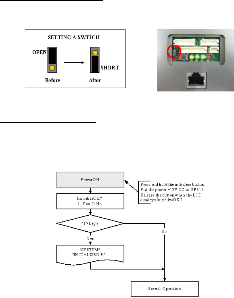
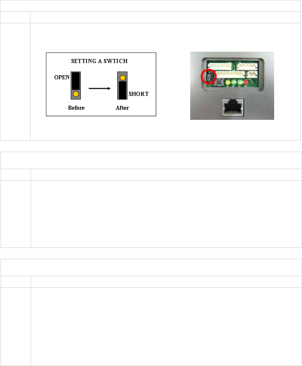
5.2 BACKUP BATTERY SWITCH
GE314 has a switch for the backup battery connection, which remains open circuit to prevent any current
consumption of the backup battery (Figure: Switch setting). Before the GE314 operation, it needs to be
connected so that the backup battery can retain the serial RTC(Date and Time data) during power failure.
Figure: SWITCH SETTING Figure: SWITCH LOCATION
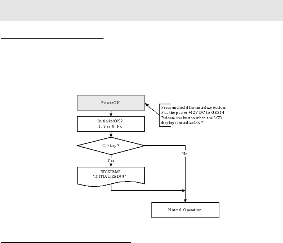
5.3 SYSTEM INITIALIZATION
After the all installation and connections are completed, press and hold the Initialize button and put the power
(+12V DC) to GE314. The LCD will first display “Initialize OK? 0:No 1:Yes”. Press <1> key if you want to
initialize the system. After all Initialization process is completed, the system is operating on normal mode and
the LCD displays “GE Security, GE314 [F1], Date Time”.
16
5.4 WALL MOUNT INSTALLATION
Position the Wall Mount to the location where you install the unit and mark 4 x drilling position. Drill 6-
32 holes at least 4 mounting point.
Drill 1/2” hole on the center of Wall Mount.
Using 4 screws, install the Wall Mount to the proper location.
Take out the cable through the center hole.
After the wiring is done on the section 8, install the Main Unit to the Wall Mount using a screw to the
bottom of the Wall Mount.
6. WIRING
6.1 POWER CONNECTION
1. Connect (+) wire of DC 12V power Supply to the Red wire.
2. Connect GND (-) wire of DC 12V power Supply to the Black wire.
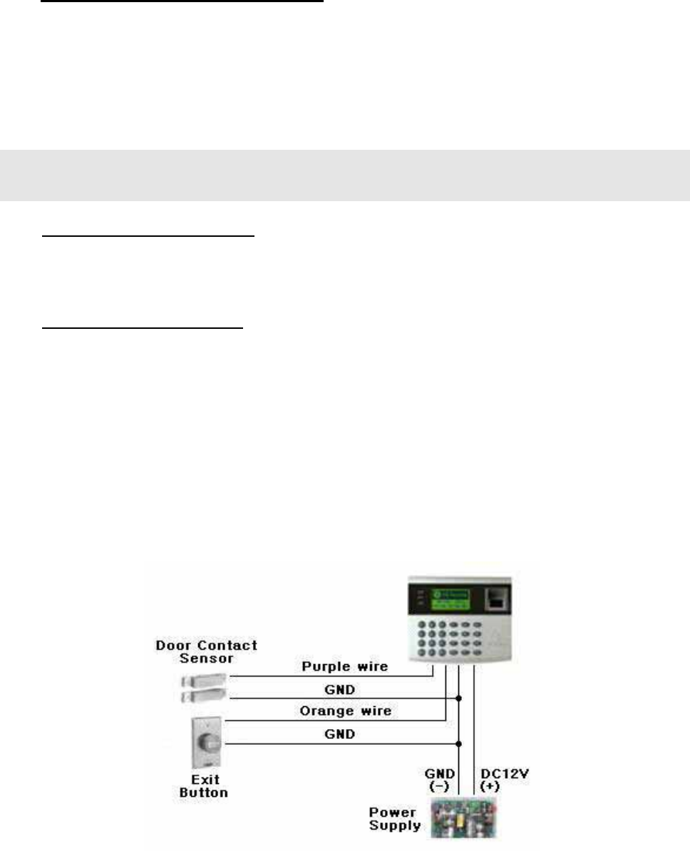
6.2 INPUT CONNECTION
Exit Button Connection
1. Connect one wire from an Exit Button to the Orange wire.
2. Connect the other wire from the Exit Button to the GND.
Door Contact Sensor Connection
1. Connect one wire from a Door Contact Sensor to the Purple wire.
2. Connect the other wire from the Door Contact Sensor to GND.
Auxiliary Input Connection
Applied to Aux Input #1(Pink wire), Aux Input #2(Cyan wire)
1. Connect one wire from an Auxiliary Input Device to one of the Aux Input #1 or Aux Input #2.
2. Connect the other wire from the Auxiliary Input Device to GND.
Figure: Input Device Connection
17
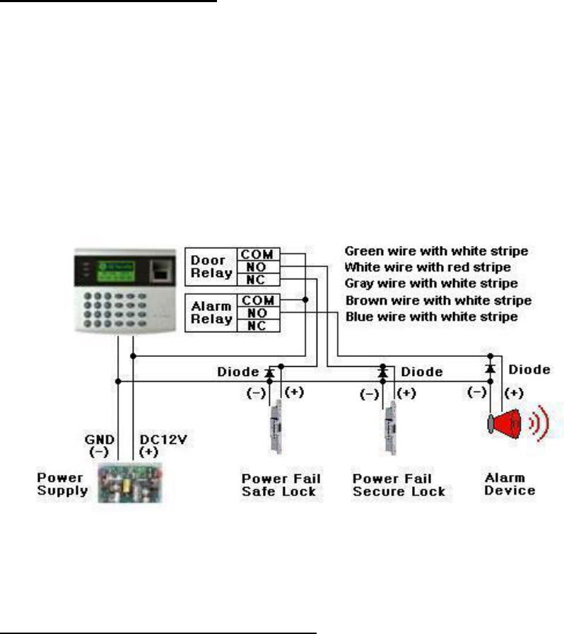
6.3 OUTPUT CONNECTION
Door Lock (Power Fail Safe) Connection (Door Relay)
1. Connect COM wire of Door Relay, the Green wire with white stripe to +12V.
2. Connect NC wire of Door Relay, the Gray wire with white stripe to (+) wire of door lock device.
3. Connect GND wire to (-) wire of door lock device.
Door Lock (Power Fail Secure) Connection (Door Relay)
1. Connect COM wire of Door Relay, the Green wire with white stripe to +12V.
2. Connect NO wire of Door Relay, the White wire with red stripe to (+) wire of door lock device.
3. Connect GND wire to (-) wire of door lock device.
Alarm Device Connection (Alarm Relay)
1. Connect COM wire of Alarm Relay, the Brown wire with white stripe to +12V.
2. Connect NO wire of Alarm Relay, the Blue wire with white stripe to (+) wire of Alarm device.
3. Connect GND port to (-) wire of Alarm device.
Figure: Door Lock, Alarm Device Connection
CAUTION: Must add REVERSE DIODE as shown above.
DIODE: Fast Recovery DIODE (current: min. 1A), 1N4004 ~ 1N4007 or similar.
6.4 EXTERNAL READER CONNECTION
Proximity Reader Connection
1. Connect (+) wire of the Proximity Reader to DC +12V.
2. Connect (-) wire of the Proximity Reader to GND.
3. Connect Data-0 wire of the Proximity Reader to the Green wire.
4. Connect Data-1 wire of the Proximity Reader to the White wire.
Compatible Reader:
GE616: Standard IDC 26bit Wiegand Format Proximity Reader.
18
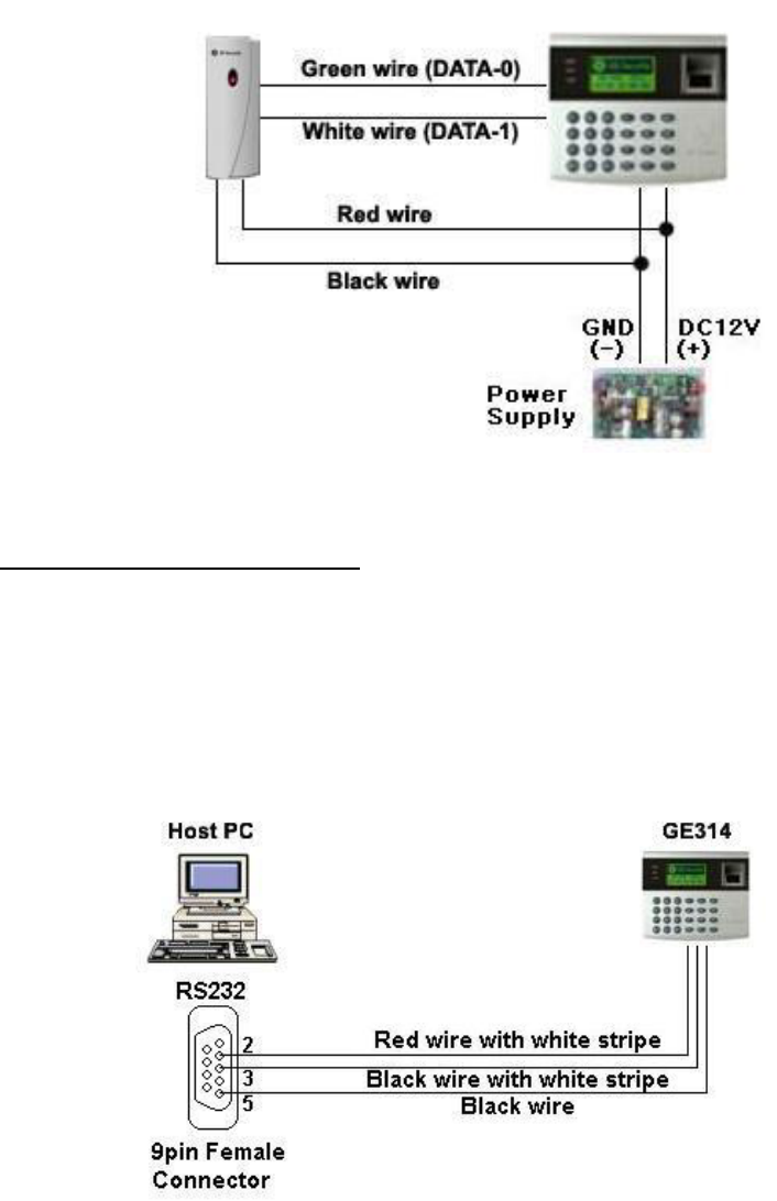
Figure: External Reader Connection
6.5 RS232 PORT CONNECTIN
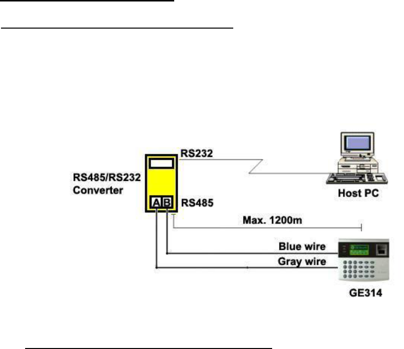
A 9-pin connector (Serial communication connector, female) is required to connect the GE314 to a host
computer via RS232 communication. Please follow the instructions.
1. Connect RS232-TX, Red wire with white stripe to the pin #2(RXD) of the 9-pin connector.
2. Connect RS232-RX, Black wire with white stripe to the pin #3(TX) of the 9-pin connector.
3. Connect GND, Black wire to the pin #5 of the 9-pin connector.
4. Plug in the 9-pin female connector to COM1 or COM2 Port of the host PC.
5. Install and run GE314 Application Software.
Figure: RS-232 COMMUNICATON
19
6.6 RS-485 PORT CONNECTION
6.6.1 RS-485 CONNECTION(SINGLE UNIT)
RS485/RS232 converter is required to use RS485 communication between the GE314 and a host PC.
Please follow the instructions.
1. Connect RS485-RTX(+), Grey wire to RS485-A port of the converter.
2. Connect RS485-RTX(-), Blue wire to RS485-B port of the converter.
3. Plug the RS232, 9-pin connector of the converter into the COM1 or COM2 Port of the host PC.
4. Install and run the GE314 Application Software.
Figure: RS-485 Connection between GE314 and a host PC
6.6.2 RS-485 CONNECTIN(MULTIPLE UNITS)
RS485/RS232 converter is required to use RS485 communication between multiple GE314 and a host PC.
Please follow the instructions.
First, you have to connect all RS485 port of GE314 in parallel. (max. 32 x GE314 Units)
1. Connect RS485-RTX(+), Grey wire of one GE314 to RS485-RTX(+), Grey wire of another GE314.
2. Connect RS485-RTX(-), Blue wire of one GE314 to RS495-RTX(-), Blue wire of another GE314.
3. Set a different COMM ID for each GE314.
Second, you have to connect one of RS485 port of GE314 to RS485/RS232 converter.
1. Connect RS485-RTX(+), Grey wire of one GE314 to RS485-A port of the converter.
2. Connect RS485-RTX(-), Blue wire of one GE314 to RS485-B port of the converter.
3. Plug the RS232, 9-pin connector of the converter into the COM1 or COM2 Port of the host PC.
4. Install and run the GE314 Application Software.
20
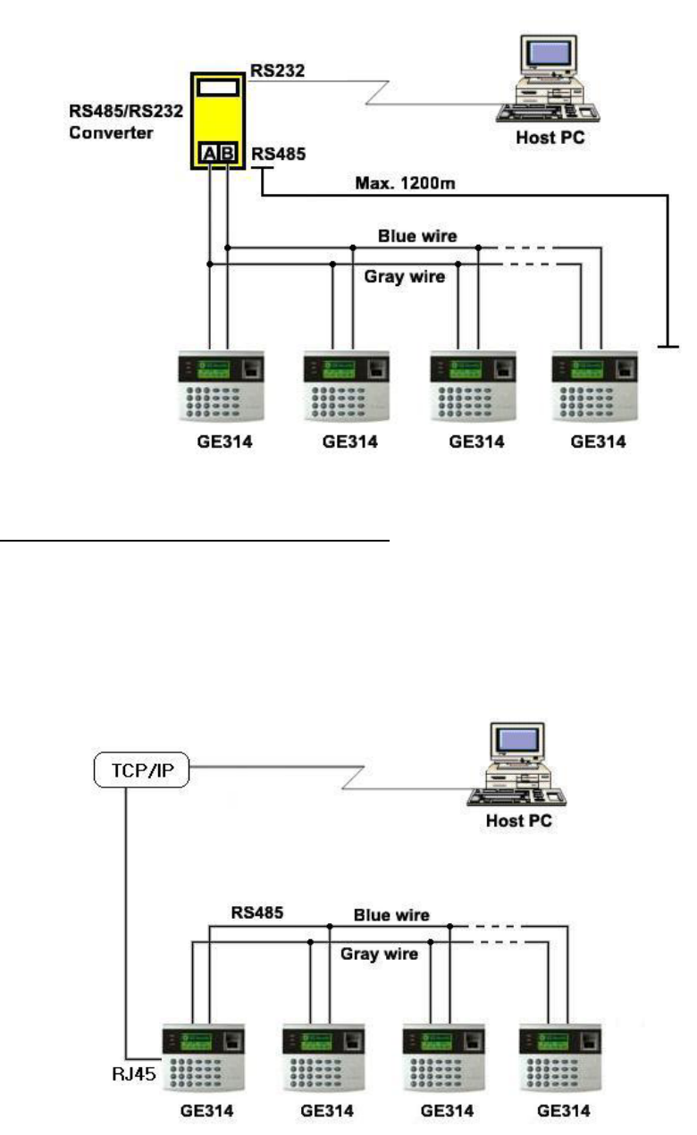
Figure: RS-485 Communication between multiple GE314 and a host PC
6.7 TCP/IP CONNECTION (OPTIONAL)
Optional TCP/IP Module is required for TCP/IP communication to the host PC.
1. Connect RJ45 plug, LAN cable of the network system to RJ45 jack of the GE314.
2. If you install multiple GE314 and only one TCP/IP port is available, you may connect one GE314 to
TCP/IP then connect all GE314 units to RS485 multiple communication shown above.
3. Set a different COMM ID for each GE314.
4. Install and run the GE314 Application Software.
Figure: TCP/IP Communication between multiple GE314 and a host PC
21
7. BASIC SETTINGS
7.1 INITIALIZATION OF GE314
After the all installation and connections are completed, press and hold the Initialize button and put the power
(+12V DC) to GE314. The LCD will first display “Initialize OK? 1:YES, 0:NO”. Press <1> key if you want
to initialize the system. After all Initialization process is completed, the system is operating on normal mode
and the LCD displays “GE Security, GE314 [F1], Date Time”.
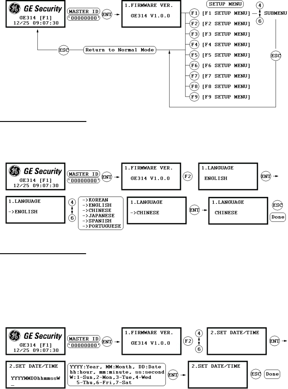
7.2 HOW TO ENTER THE SETUP MENU
To setup or to change the GE314 settings, you have to enter the SETUP MENU first. To do so, press <0> key
eight times (Default Master ID ‘00000000’) and <ENT> key from the Keypad. You now entered to the
SETUP MENU. There are 9 SETUP MENU and you first get into [F1 SETUP MENU]. You can move to
another SETUP MENU by pressing <F1> key to <F9> key button. For example, if you want to go to [F2
SETUP MENU] then press <F2> key, for [F5 SETUP MENU] then press <F5> key and so on. There are
several SUBMENU on each SETUP MENU and you can scroll up and down the SUBMENU by pressing
<4> and <6> key on each SETUP MENU. If you don’t press any key for 60 seconds or if you press <ESC>
key, GE314 will exit the SETUP MENU and return to normal operation mode. You can also change the
Master ID in the [F4 SETUP MENU].
22
7.3 LANGUAGE SETTING
Select [LANGUAGE] in the [F2 SETUP MENU] then press <ENT> key to select the LANGUAGE. Please
follow the steps below for LANGUAGE setting and following procedure is for selecting CHINESE.
7.4 DATE/TIME SETTING
Select [SET DATE/TIME] in the [F2 SETUP MENU] and enter Year / Month / Date / Hour / Minute /
Second / Day (Total 15 digits) as shown below. The LCD will display the new Date and Time after the time
setting is completed but the year and day will not be displayed. GE314 has a 24 hours system and day codes
are 1 for Sunday, 2 for Monday, 3 for Tuesday, 4 for Wednesday, 5 for Thursday, 6 for Friday and 7 for
Saturday.
23
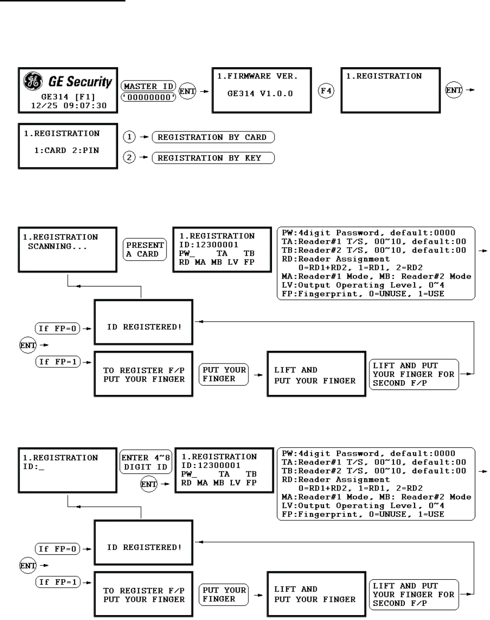
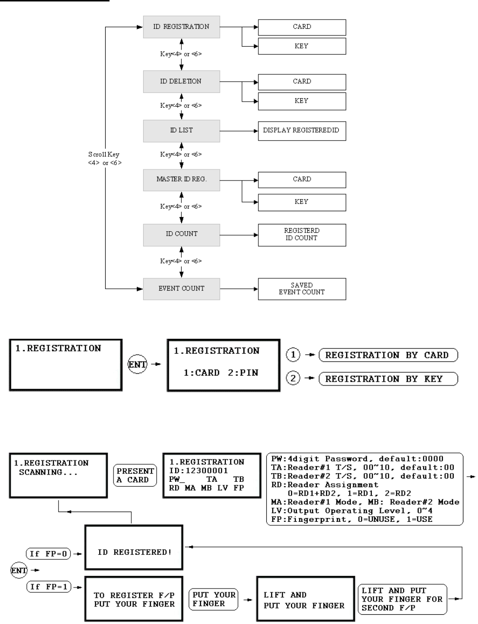
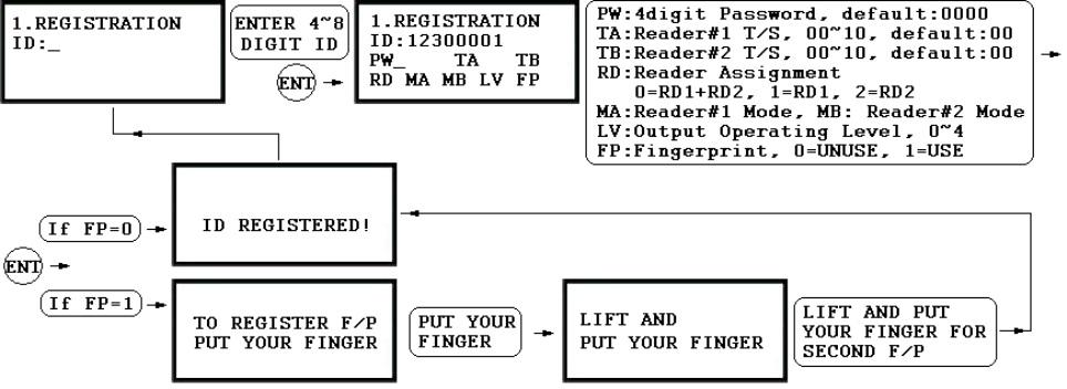
7.5 ID REGISTRATION
You can register the User ID into the GE314. Select [F4 SETUP MENU] -> [REGISTRATION] and follow
the steps below.
1. Registration by Card
2. Registration by Key
24
1. Scanning… The reader is waiting for the ID number to be registered. The card number will appear with a
beep sound when you present the card. ID number is 8digit number.
2. ID: ID number consists of 4~8 digit. Enter 4~8digit ID number (PIN) and press <ENT> key on the field.
3. PW: PW is the password which can be used to access the doors with RF + Password operating mode. It is
necessary to enter a default password (‘0000’) when you register an ID.
4. TA: TA is the Time Schedule code (‘00’ ~ ‘10’) for the Reader#1 (Built-in Reader). When you present the
card to the Reader#1, the cardholder is only allowed the access of the door during the Time intervals of the
Time Schedule code entered to TA. To setup the Time intervals for each Time Schedule code, refer to the
ard to the Reader#2, the cardholder is only allowed the access of the door during the Time intervals of the
the door anytime for the cardholder
en enter the default Time Schedule code '00' for the value.
n
ns
ss Door Error”) on the LCD display.
A,
‘3’ – ID + Password + Finger Mode
‘1’ – ID Only Mode
Time Schedule Setup on the [F5 SETUP MENU]. If you want to access the door anytime for the cardholder
then enter the default Time Schedule code '00' for the value.
5. TB: TB is the Time Schedule code (‘00’ ~ ‘10’) for the Reader#2 (Exit Reader). When you present the
c
Time Schedule code entered to TB. To setup the Time intervals for each Time Schedule code, refer to the
Time Schedule Setup on the [F5 SETUP MENU]. If you want to access
th
6. RD: RD is the Reader Assignment code for the cardholder. Code ‘0’ assigns for both readers (Built-i
Reader and Exit Reader), code ‘1’ only assigns Reader#1 (Built-in Reader) and code ‘2’ only assig
Reader#2 (Exit Reader). If you put ‘1’ for RD (Only Reader#1 assigned) and try to exit through Reader#2
(Exit Reader) then GE314 generates an error message (“Acce
7. MA: MA is the Reader#1 (Built-in Reader) Operating Mode for the cardholder. If you put ‘1’ for M
Reader#1 is always operating on RF Only Mode.
‘0’ – System Operating Mode [F2 SETUP MENU] [READER#1 MODE]
‘1’ – ID Only Mode
‘2’ – ID + Finger(Password) Mode
8. MB: MB is the Reader#2 (Exit Reader) Operating Mode for the cardholder. If you put ‘1’ for MB,
Reader#2 is always operating on RF Only Mode.
‘0’ – System Operating Mode [F2 SETUP MENU] [READER#2 MODE]
‘2’ – ID + Password Mode
25
9utput Operating Level for the cardholder. Output operating time can be set for . LV: LV is the O each user.
evel, refer to the Output Setting on the [F7 SETUP MENU].
‘3’ – Level #3
0. FP: FP is the Fi not.
nt
3.
hen you enroll or verify y place your finger to the scanner correctly.
To setup Output operating time for each l
‘0’ or ‘1’ – Level #1
‘2’ – Level #2
‘4’ – Level #4
1ngerprint Usage Flag (1 digit). You can assign the user who uses fingerprint or
‘0’ – User without Fingerpri
‘1’ – User with Fingerprint
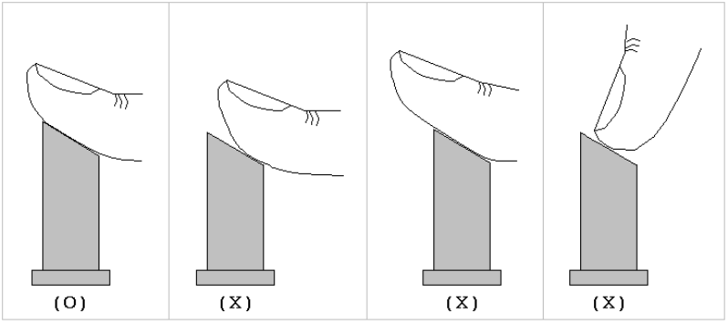
How to put your finger to the scanner
Wour fingerprint, please
Figure: How to put your finger to the scanner
26

8. OPERATION
8.1 NORMAL OPERATION
Power on
When the power is applied to GE314, the Red LED is turned on.
Registered card reading
When a registered card (or PIN) is read and his/her fingerprint is verified, the Door (Relay#1) will open for 3
seconds (Default) with the Green LED on.
Exit Button
When the Exit button is pressed, the Door (Relay#1)
Alarms
When an unregistered card is read or his/her fingerprint is not verified, the access is denied and the Alarm
(Relay#2) will be activated for 3 seconds with the Yellow LED on.
8.2 DEFAULT SETTING
will open for 3 seconds with the Green LED on.
When you operate the system for the first time or the system initialized, the factory setting values (default
ory. You may change the settings for the desired application.
settings) will be stored in the mem
27
9
. SETTING CHANGES
☞. To setup or to change the GE314 settings, you have to enter the SETUP MENU first. To do so, press <0> key
eight times (Default Master ID ‘00000000’) and <ENT> key from the Keypad. You now entered to the
SETUP MENU. There are 9 SETUP MENU and you first get into [F1 SETUP MENU]. You can move to
another SETUP MENU by pressing <F1> key to <F9> key button. For example, if you want to go to [F2
SETUP MENU] then press <F2> key, for [F5 SETUP MENU] then press <F5> key and so on. There are
several SUBMENU on each SETUP MENU and you can scroll up and down to SUBMENU by pressing <4>
and <6> key on each SETUP MENU. If you don’t press any key for 60 seconds or if you press <ESC> key,
GE314 will exit the SETUP MENU and return to normal operation mode. You can also change the Master ID
in the [F4 SETUP MENU].
28
29
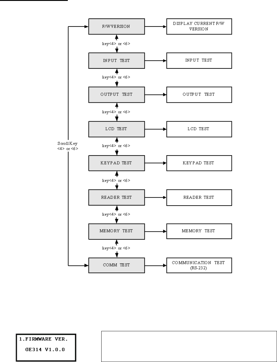
9.1 F1 SETUP MENU
9.1.1 VERSION CHECK
☞. The Firmware Version of the GE314 displays on the LCD.
Press <4> or <6> key to have a look for other menus on
[ F1 SETUP MENU]
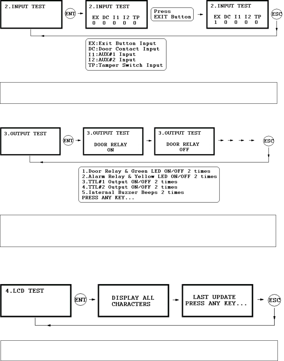
9.1.2 INPUT TEST
9.1.4 LCD TEST
9.1.5 KEYPAD TEST
9.1.3 OUTPUT TEST
. The ☞5digit shows the input status and “0” indicates that the input port is open circuit and “1” indicates that the
input port is short circuit to ground level.
☞. The first two tests are for the output relays (Door Relay and Alarm Relay) test. You can hear the mechanical
sound of relays and LED will blink. Following two tests are for TTL#1 and TTL#2 output testing. The last
test is for the Internal Buzzer test and you can hear two beep sounds.
☞. The LCD will display all characters on the screen. When the test is done, the LCD will show “Last Update
Press any key”.
30
.1.
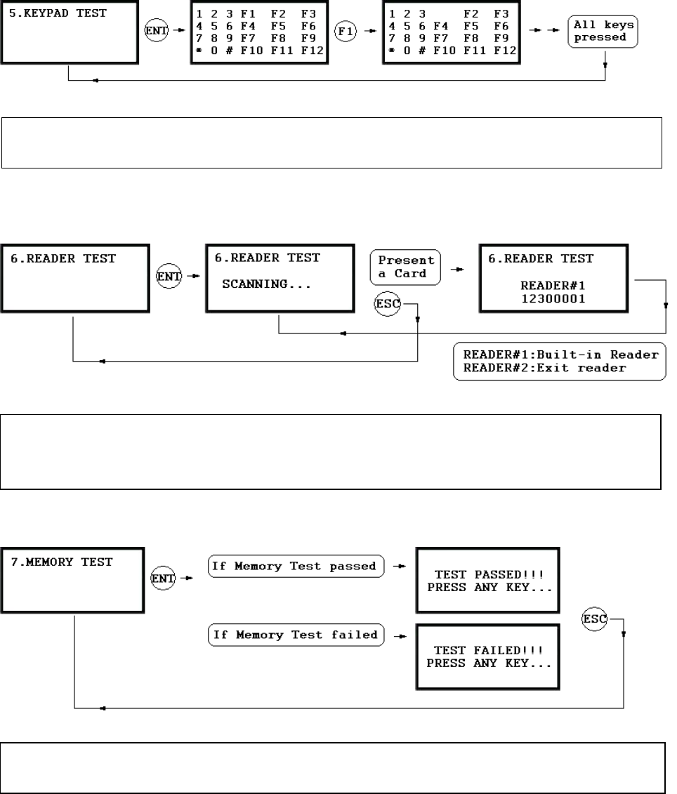
9 6 READER TEST
9.1.7 MEMORY TEST
☞. LCD will display all keys of the unit. Press each key from the keypad one by one, the depressed key will
disappear from the LCD. Note that ENT key is “#” and ESC key is “*” on the LCD.
☞. LCD will display “Scanning…” for reading the cards. Present the card to one of the readers.
☞. When the reader successfully read the card, LCD will display Reader number and 8digit card number on the
LCD.
☞. If the Data Memory has problems, LCD will show the memory block number with Memory failure message.
In this case, contact manufacturer for technical support.
31
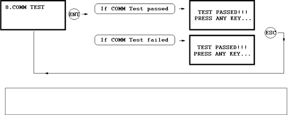
9.1.8 COMMUNICATION TEST
. ☞Before this communication test, connect RS232-RX and RS232-TX wires together.
. ☞This test is a loop test and GE314 sends a character to RS232-TX and check whether the RS232-RX receive
the same character or not. If you have an error, contact manufacturer for technical support.
32
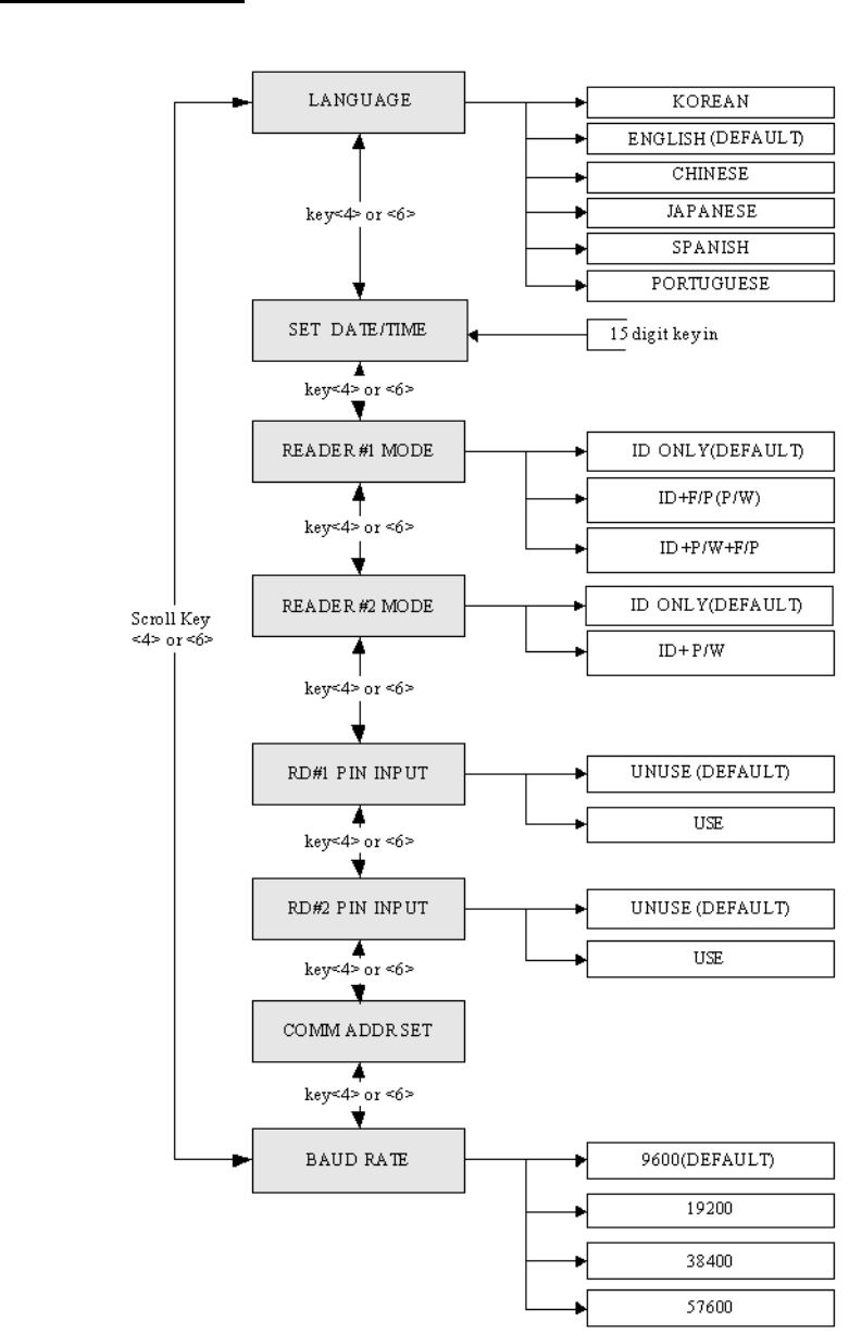
9.2 F2 SETUP MENU
33
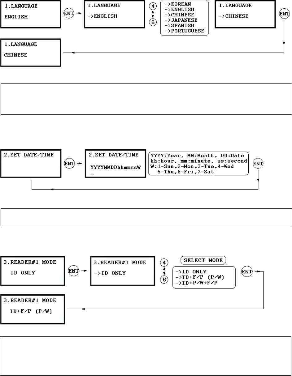
9.2.1 LANGUAGE
9.2.2 DATE AND TIME SETTING
9.2.3 READER#1 MODE
☞. The default Language is in ENGLISH.
☞. There are 6 languages can be selected. (KOREAN, ENGLISH, CHINESE, JAPANESE, SPANISH,
PORTUGUESE)
☞. Example: 200302101330152 => Feb. 10, 2003, 13:30:15, Monday
Note: READER#1 is built-in proximity reader in the unit.
ID(PIN) ONLY: The door is accessible by just presenting the proximity card(or Press the ID Number).
ID+F/P(P/W): The door is accessible by presenting a card and verifying Fingerprint (or Password).
ID+P/W+F/P: The door is accessible by presenting a card and verifying Password and Fingerprint.
34
9.2.4 READER#2 MODE
READER#2 MODE setting is the same as 9.2.3 READER#1 MODE setting.
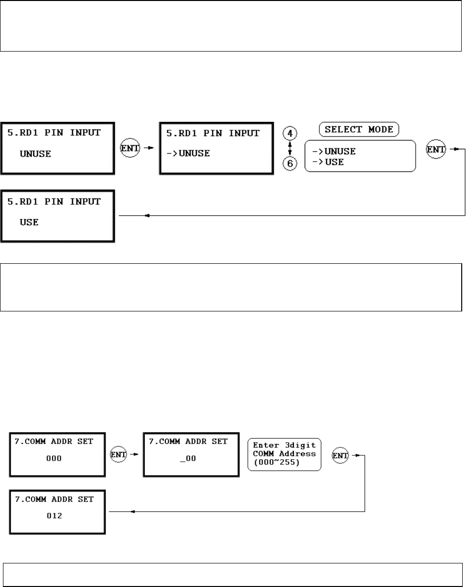
.2.5 READER#1 PIN INPUT
9.2.6 READER#2 PIN INPUT
READER#2 PIN INPUT setting is the same as 9.2.5 READER#1 PIN INPUT setting.
9.2.7 COMMUNICATION ADDRESS SETTING
9
. ☞The default Communication Address is “000” and set a different COMM Address for each unit in the loop.
☞. This function is for USE/UNUSE the keypad inputs for the Reader#1. The default setting is UNUSE the
keypad inputs. If you want to access the door by entering the user ID by keypad, set this mode USE. Yo
u
have to set this mode USE when the unit is operating with Password.
Note: READER#2 is an external Exit reader of the unit.
ID(PIN) ONLY: The door is accessible by just presenting the proximity card(or Press the ID Number).
ID+ P/W: The door is accessible by presenting a card and Password.
35
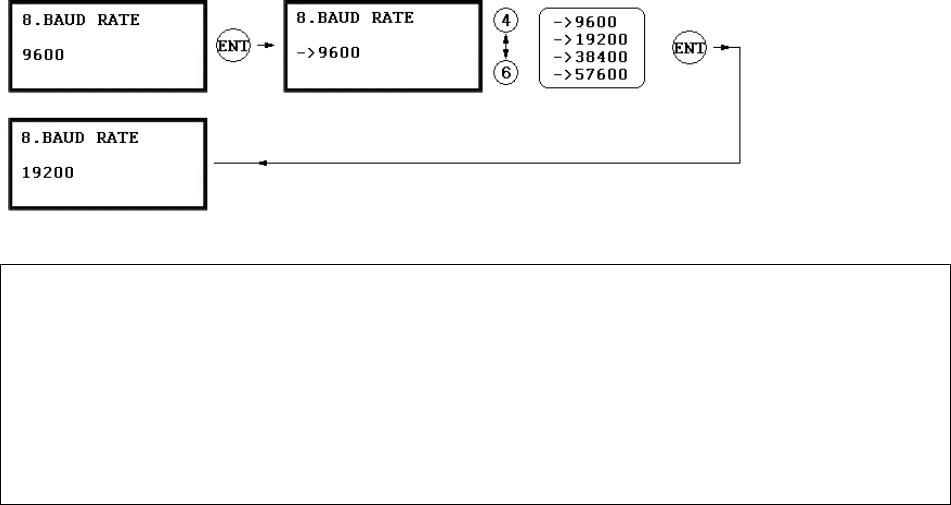
9.2.8 BAUD RATE SETTING
☞. GE314 supports 9600, 19200, 38400 and 57600bps of Baud Rate and default Baud Rate is 9600bps. Wrong
Baud Rate setting will cause communication error and you have to set same Baud Rate for the same
communication network.
If you have communication problem, please check followings;
- Check Communication Address for both GE314 and the host PC (Software)
- Check Baud Rate for both GE314 and host PC
- Check Communication Port and Cable
- Check COM port setup of the host PC
Parity: None, Data Bit: 8 bit, Stop Bit: 1 bit
36
9.3 F3 SETUP MENU
37
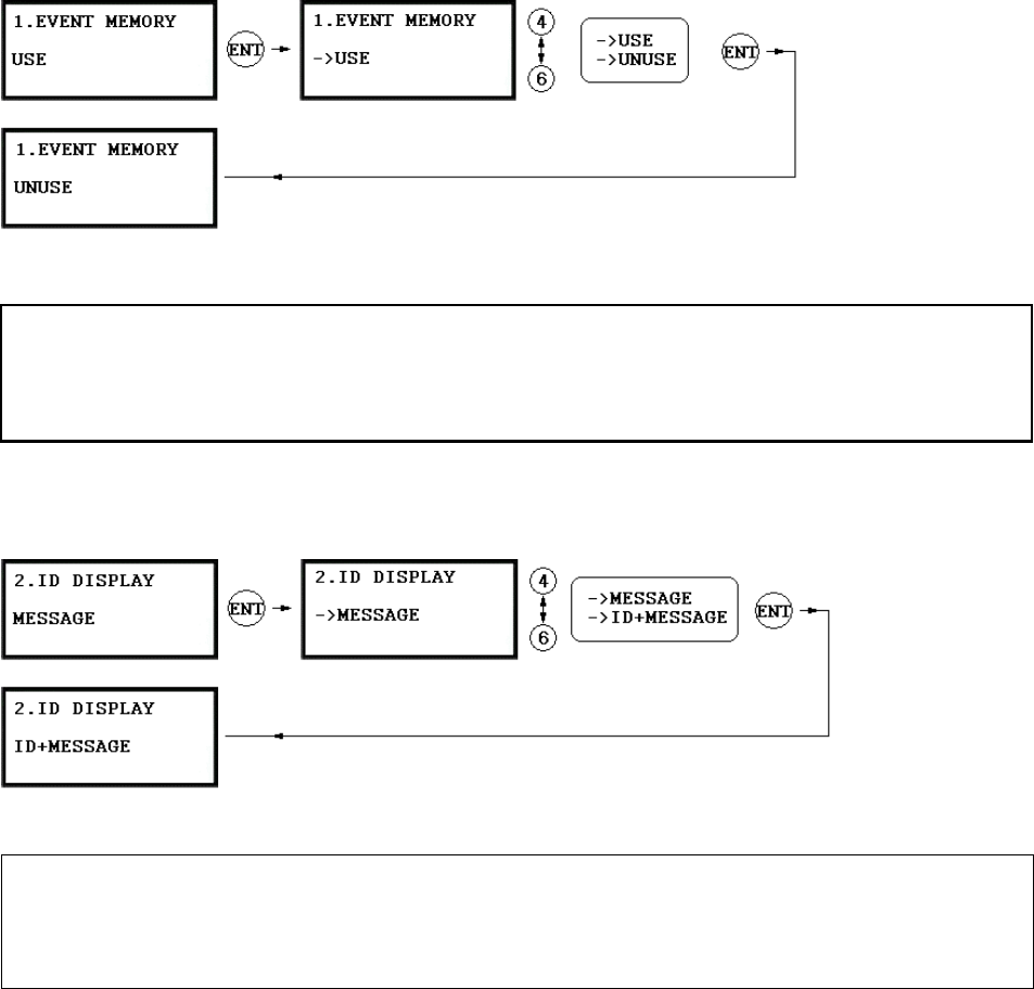
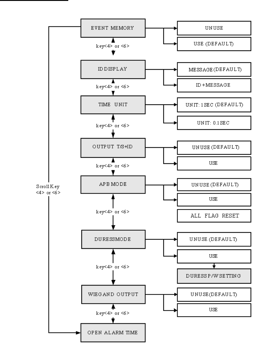
9.3.1 EVENT MEMORY
9.3.2 ID DISPLAY
☞. This function is to set display mode. If you want to display user ID number on the LCD, selec
t
ID+MESSAGE. MESSAGE: Text message and “********” characters will be displayed on the LCD and i
t
will not display user ID number. ID+MESSAGE: The user ID number will be displayed on the LCD with tex
t
message. Default setting is MESSAGE only.
☞. ☞. You can select whether you will use event memory or not. When you select USE and in case of an even
t
memory, GE314 generates an error message and keeps all events stored in the memory. When you selec
t
UNUSE, GE314 will not generate an error and new event overwrite into the event buffers. If you use GE314
for standalone (just for door access), select UNUSE.
38
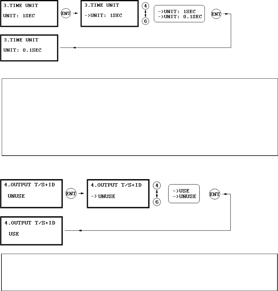
9.3.3 TIME UNIT SETTING
.3.4 OUTPUT T/S+ID
- Set Output Tim
. s menu is to define time unit for 5 output ports.
1sec: Output Time will be calculated by one second time unit for in/out definition.
0.1sec: Output Time will be calculated by 1/10 second time unit (100ms) for in/out definition
If you want to activate Door Relay (Relay #1, DR) for
☞Thi
Ex) 3 second, you have to set as follow.
- Set Output Time Unit to 1 SEC.
- Set Door Relay (DR) Output Time to “03”
x) ) If you want to activate Door Relay (Relay #1, DR) for 0.5 second, you have to set as follow.
e Unit to 0.1 SEC.
- Set Door Relay (DR) Output Time to “05”
E
9
Output Time Schedule+ID is to unlock the do
☞. or when the first user grants the access during the Time Interval
of the Time Schedule. The door will be locked just after the Time Interval period is over.
UNUSE: Door will unlock at the beginning of the Time Interval of the Time Schedule code.
USE: Door will unlock when the first user grants the access during the Time Interval of the Time Schedule.
39
9.3.5 ANTI-PASS BACK MODE
9.3.
9.3.7 WIEGAND OUTPUT
☞. You can set Duress Mode for Reader#1. Default setting is UNUSE. If you select USE, LCD will display
default Duress Password ‘00’. Enter 2 digit Duress Password.
Note!!
ost PC.
6 DURESS MODE
. The Anti-pass Back mode is only used when you installed Exit Reader. Do not se
you installed Exit Button. You must install GE314 for entry and Exit Reader for Exit.
UNUSE: Anti-pass Back mode OFF
USE: Anti-pass Back mode ON
ess only one time whatever the Anti-pass Back flag is. ☞. ALL FLAG RESET: Allow the acc
If you are in Duress condition, enter 2 digit Duress Password and press <ENT> key prior to present the card.
Door will be opened as normal but the Duress Alarm will be generated and reported to the h
☞t this mode in USE when
40
☞. This is the function to use GE314 a
9.3.8 DOOR OPEN ALARM TIME SETTING
Open Alarm. To use t
☞. When the door is not closed after the door open time is over, you may set the delay time to generate Doo
r
his function, you have to install a Door Contact Sensor on the door and setup the alar
m
time by Door Contact Sensor. ‘03’ sec. is default time.
00: Alarm if the door is not closed after the door open time (Door Relay time).
01~98: Alarm if the door is not closed after the door open time and over the alarm delay time. (01~98s)
99: No Door O
p
en Alar
m
s a Reader and sends 26bit Wiegand Output through two TTL output ports.
Press <ENT> key and select USE by pressing <4> or <6> key then press <ENT> key for setting.
UNUSE: Normal TTL outputs will be activated.
USE: 26bit Wiegand output will be generated through TTL1 and TTL2 port.
When an registered card is read, the “CARD SCCANNING OK” message will appear on the LCD.
TTL1 : Data 0 TTL2 : Data 1
41
9.4 F4 SETUP MENU
9.4.1 ID REGISTRATION
1. Registration by RF Card
42
43
Keypad
1. Scanning… The reader is waiting for the ID number to be registered. The card number will appear with a
beep sound when you present the card. ID number is 8digit number.
2. ID: ID number consists of 4~8 digit. Enter 4~8digit ID number (PIN) and press <ENT> key on the field.
3. PW: PW is the password which can be used to access the doors with RF + Password operating mode. It is
necessary to enter a default password (‘0000’) when you register an ID.
4. TA: TA is the Time Schedule code (‘00’ ~ ‘10’) for the Reader#1 (Built-in Reader). When you present the
card to the Reader#1, the cardholder is only allowed the access of the door during the Time intervals of the
Time Schedule code entered to TA. To setup the Time intervals for each Time Schedule code, refer to the
Time Schedule Setup on the [F5 SETUP MENU]. If you want to access the door anytime for the cardholder
then enter the default Time Schedule code '00' for the value.
5. TB: TB is the Time Schedule code (‘00’ ~ ‘10’) for the Reader#2 (Exit Reader). When you present the
2. Registration by
card to the Reader#2, the cardholder is only allowed the access of the door during the Time intervals of the
Time Schedule code entered to TB. To setup the Time intervals for each Time Schedule code, refer to the
Time Schedule Setup on the [F5 SETUP MENU]. If you want to access the door anytime for the cardholder
then enter the default Time Schedule code '00' for the value.
6. RD: RD is the Reader Assignment code for the cardholder. Code ‘0’ assigns for both readers (Built-in
Reader and Exit Reader), code ‘1’ only assigns Reader#1 (Built-in Reader) and code ‘2’ only assigns
Reader#2 (Exit Reader). If you put ‘1’ for RD (Only Reader#1 assigned) and try to exit through Reader#2
(Exit Reader) then GE314 generates an error message (“Access Door Error”) on the LCD display.
43
7. MA: MA is the Reader#1 (Built-in Reader) Operating Mode for the cardholder. If you put ‘1’ for MA,
Reader#1 is always operating on RF Only Mode.
‘0’ – System Operating Mode [F2 SETUP MENU] [READER#1 MODE]
‘1’ – ID Only Mode
‘2’ – ID + Finger Mode
‘3’ – ID + Password + Finger Mode
8. MB: MB is the Reader#2 (Exit Reader) Operating Mode for the cardholder. If you put ‘1’ for MB,
Reader#2 is always operating on RF Only Mode.
‘0’ – System Operating Mode [F2 SETUP MENU] [READER#2 MODE]
‘1’ – ID Only Mode
‘2’ – ID + Password Mode
operating time can be set for each user.
o setup Output operating time for each level, refer to the Output Setting on the [F7 SETUP MENU].
‘2’ – Level #2
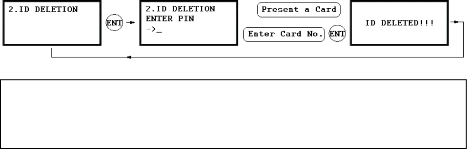
9.4.2 ID DELETION
9. LV: LV is the Output Operating Level for the cardholder. Output
T
‘0’ or ‘1’ – Level #1
‘3’ – Level #3
‘4’ – Level #4
10. FP: FP is the Fingerprint Usage Flag (1 digit). You can assign the user who uses fingerprint or not.
‘0’ – User without Fingerprint
‘1’ – User with Fingerprint
. ☞Registered ID will be deleted in the controller by presenting the card or input the ID number from the keypad.
Present the card to be deleted. The ID number will appear on the LCD. If you don’t have the card, input 8digi
t
ID
DELETED”
D
number and <ENT> key from the keypad. If the ID number is found, the ID will be deleted and display “ID
. If the ID number is not found, the display will show “ UNREGISTERED ID”. You may repeat ID
ELETION many times.
44
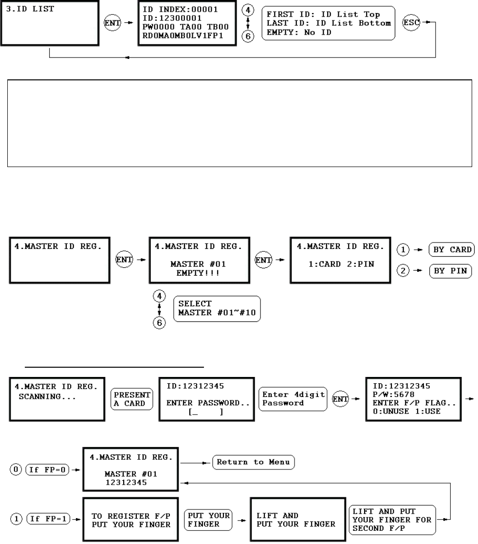
9.4.3 ID
9.4.4 M
TER ID REGIST
LIST
. LCD will display 5digit ID Index, 8digit I☞D number, 4digit Password, T/S for Reader#1(TA) an
d
Reader#2(TB), accessible Readers(RD), operating mode for Reader#1(MA) and Reader#2(MB), the outpu
t
level(
. ☞“E gistered user ID.
. ☞“FIRST ID” message
. ☞“LAST ID” message w isplays the ID on the bottom of the list.
LV) and usage of Fingerprint(FP) for this user.
MPTY” message will be displayed if there is no re
will be displayed if the LCD displays the ID on the top of the list.
ill be displayed if the LCD d
ASTER ID REGISTRATION
MAS RATION BY CARD
45
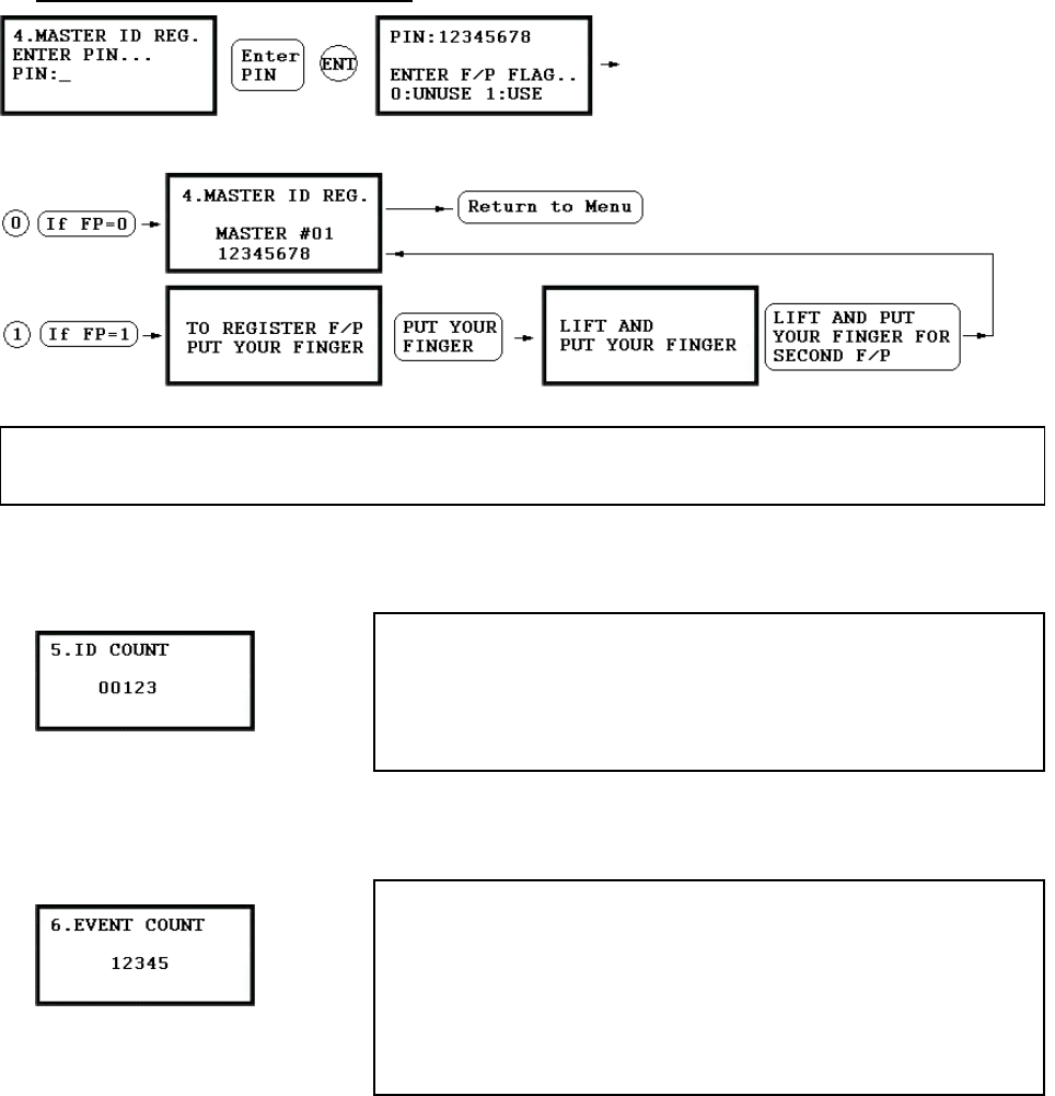
MASTER ID REGISTRATION BY PIN
☞. This menu displays the total number of registered user ID. I
9.4.5 ID COUNT
t
automatically counts when you register or delete user IDs. The LCD
shows total 123 user IDs registered in the memory.
☞. Total number of user IDs is 1,000 user IDs (standard) or optional
2,000/4,000 user IDs can be stored in the unit.
. ☞The default Master ID ‘01’ is “00000000” and Fingerprint is not used.
There are total 10 Master IDs (from “01” to “10”) can be stored in the unit.
9.4.6 EVENT COUNT
☞. This menu displays the total number of Event stored in the memory.
It automatically increases the count when the Event is stored in the
memory. The LCD shows total 12345 Events are stored in the
memory.
☞. Total number of Event is 20,000 Event buffers and the Event is
automatically deleted once the Event is successfully uploaded to the
host PC.
46
9.5 F5 SETUP MENU
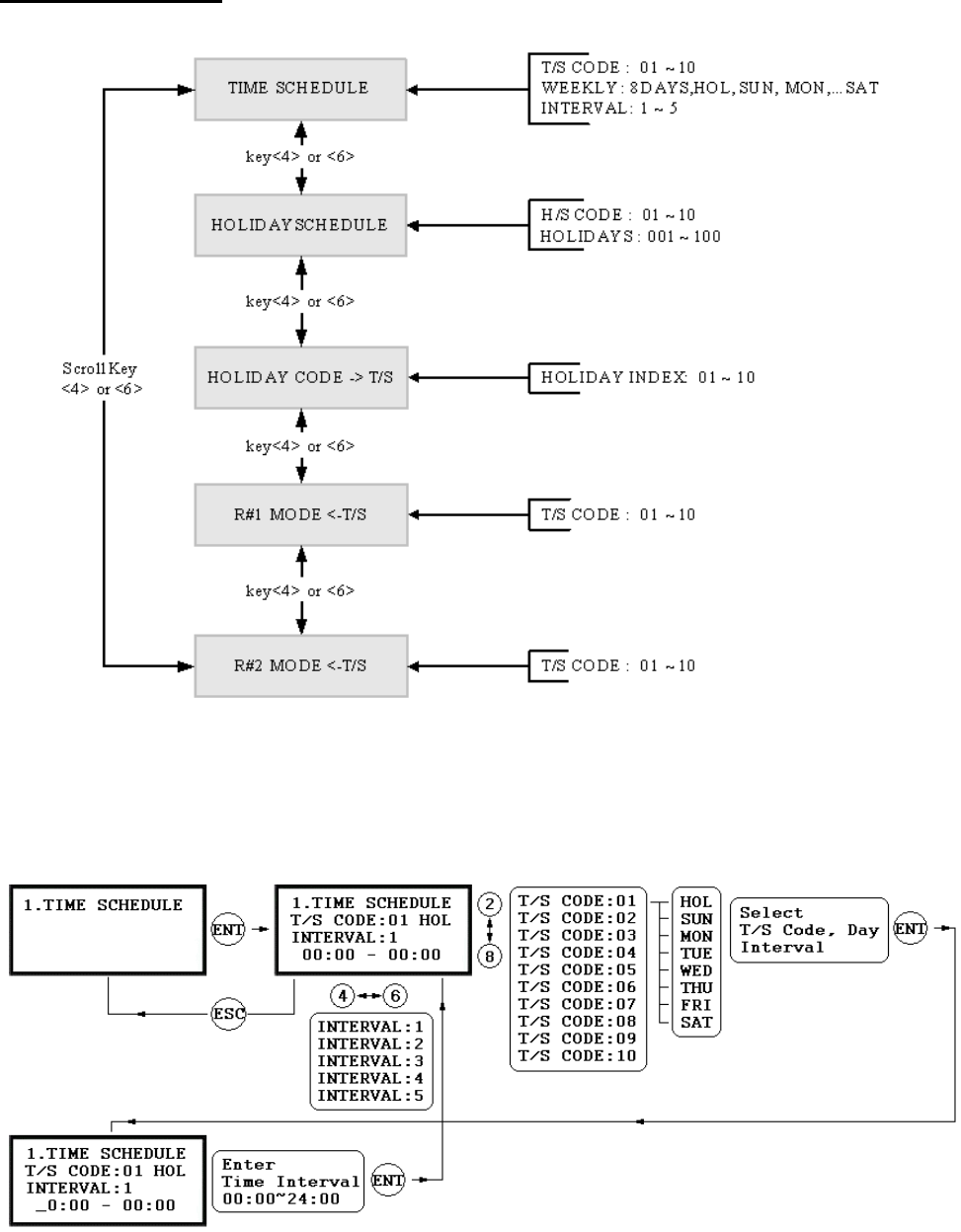
9.5.1 TIME SCHEDULE
47

48
9.5.2 HOLIDAY SCHEDULE
☞. There are 10 Time Schedule Code available for the users. T/S Code “00” is a default and allows the access fo
r
all users for all the time. (Access is granted 24 hours per day) The user can program the Time Schedule Code
from “01” to “10”. Each Time Schedule Code has 8 programmable days (Sun, Mon, Tue, Wed, Thu, Fr Sai,
t
and Holiday) and each day has 5 Time Intervals. (Shift time or Accessible time zone)
☞. LCD will show current T/S settings such as T/S Code, Day, Time Interval and time period.
Use <2> or <8> key to scroll up and down the Time Schedule Code (01~10) and a day of the week. (M no
~
Sun and Holiday). Use <4> or <6> key to select Time Interval (1 ~ 5). The Holiday in this Time Schedu
be linked to the Holiday Schedule Code.
Select one of the Time Schedule Code, Day and Interval then press <ENT> key to program the time period.
This system is based on 24 hours system and therefore the time 00:00 and 24:00 is the same time and 12 0 is
12 O’clock afternoon. Enter hour and minutes for start time and hour and minutes for end time of the Time
Interval then press <ENT> key to store T/S to the memory.
Press <ESC> key to return to the menu.
le will
:0
☞. There are 10 Holiday Schedule Code available r the users. H/S Code “00” is a default and there is no
Holidays in this code. The user can program the Holiday Schedule Code from “01” to “10”. Each Holiday
Schedule Code has 100 programmable holidays.
☞. LCD will show current H/S settings such as H/S Code, Holiday number and Date.
Use <2> or <8> key to scroll up and down the H iday Schedule Code (01~10) and use <4> or <6> key to
select Holiday number (001 ~ 100).
Select one of the Holiday Schedule Code and Holi number then press <ENT> key to program holidays.
Enter month and date of holiday then press <ENT> key to store H/S to the memory.
Press <ESC> key to return to the menu.
fo
ol
day
9.
.5.5 R ULE
READER#2 MODE TIME SCHEDULE setting is the same as 9.5.4 READER#1 MODE T/S setting.
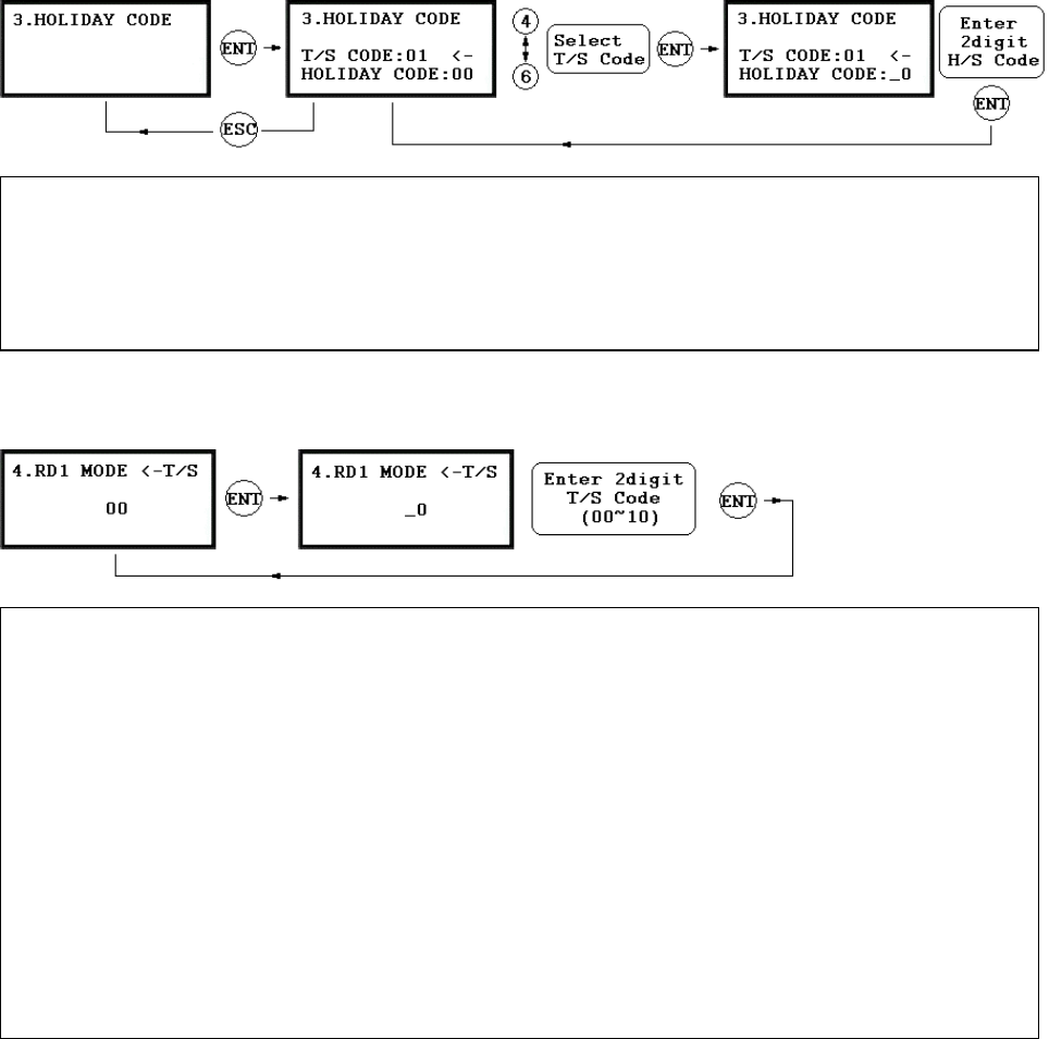
5.3 HOLIDAY CODE
oliday Code is to link the Holiday Schedule to the Time Schedule. T/S has 5 Time Intervals for holidays an
d
th ay Schedule. Default Holiday Schedule Code is
‘ o T/S.
Use <4> or <6> key to scroll up and down the T/S Code (01~10) and press <ENT> key to enter 2digit Holida
is Time Intervals are only applied to the dates of this Holid
00’ which means no holidays are applied t
9.5.4 READER#1 MODE TIME SCHEDULE
EADER#2 MODE TIME SCHED
Press <ESC> key to return to the menu.
. There are 3 system operating mode, ☞ID Only Mode, ID + Finger(Password) Mode and ID + PW + Finger
ode.
ou can select one of the system operating mode fr
however, you want to apply different operating mode
‘2’ – RF + Finger Mode
‘3’ – RF + PW + Finger Mode
☞. H
y
Schedule Code and press <ENT> key to store Holiday Index to the memory.
Press <ESC> ke
y
to return to the menu.
☞. There are 3 system operating mode, RF Only Mode, RF+F/P Mode and RF+PW+F/P Mode. You can setup one
of the system operating mode from [F2 SETUP MODE]->[R1 MODE SETTING] menu. However, you wan
t
to apply different operating mode for a certain Time Interval for all users. For example, you want to access the
door by just presenting the card for the time from 09:00 to 17:00 and you want to use Fingerprint verificatio
n
for the rest of the time. In this case, setup [R1 MODE SETTING] to RF+F/P Mode which is for the syste
m
operating mode and program “01” T/S Code which includes a Time Interval 09:00-17:00 then link “01” T/S
Code to this function, R1 MODE T/S setting here.
To link a T/S Code (01~10) to Reader#1 Mode, press <ENT> key. Enter 2digit T/S Code and press <ENT>
key to store T/S Code to R1 MODE to the memory.
M
Y om [F2 SETUP MENU]->[READER#1 MODE SETTING]
9
49
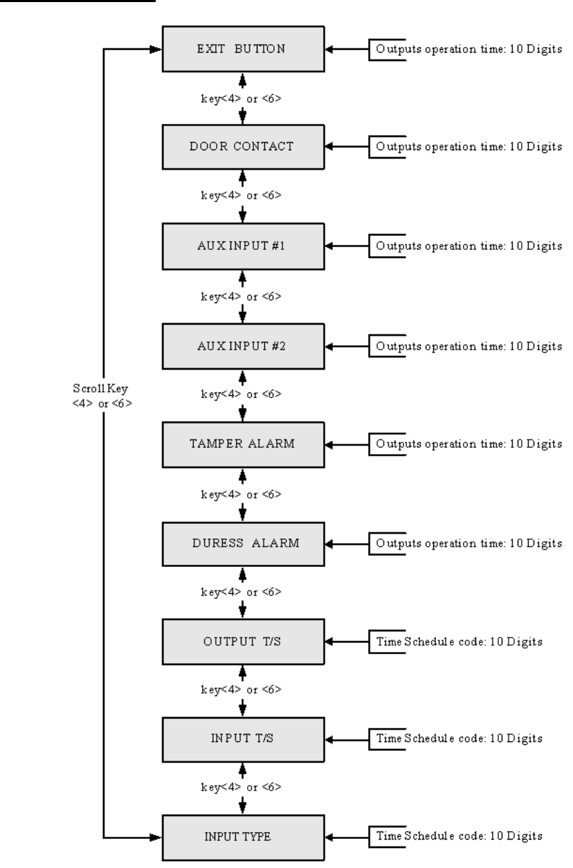
9.6 F6 SETUP MENU
50
* Default Output Setting for Input Sources
9.6.1 EXIT BUTTON OUTPUT SETTING
9.6.2 DOOR CONTACT OUTPUT SETTING
9.6.3 AUX INPUT#1 OUTPUT SETTING
9.6.4 AUX INPUT#2 OUTPUT SETTING
9.6.5 TAMPER ALARM OUTPUT SETTING
9.6.6 DURESS ALARM OUTPUT SETTING
Output Time setting for above Input Sources are the same as 9.6.1 Exit Button Output setting.
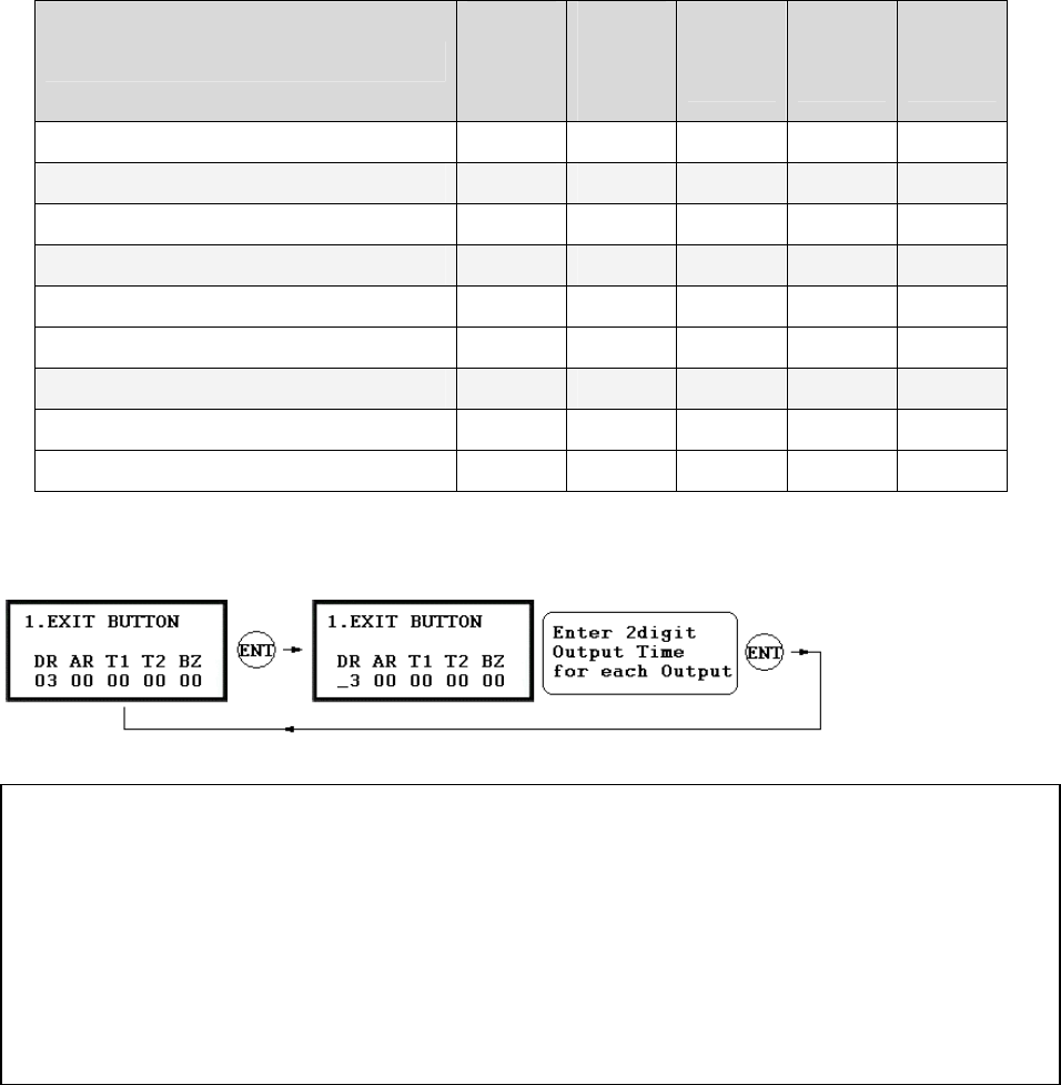
OUTPUT
Door
Relay
(DR)
Alarm
Relay
(AR)
TTL#1
(T1)
TTL#2
(T2)
Buzzer
(BZ)
[1] EXIT BUTTON 03 00 00 00 00
[2] DOOR CONTACT 00 99 00 00 00
[3] AUX Input #1 00 00 00 00 00
[4] AUX Input #2 00 00 00 00 00
[5] TAMPER ALARM 00 99 99 99 99
[6] DURESS ALARM 00 00 00 00 00
[7] OUTPUT TIME SCHEDULE 00 00 00 00 00
[8] INPUT TIME SCHEDULE 00 00 00 00 00
[9] INPUT TYPE 00 00 00 00 00
. You can program ☞OUTPUT activating time when the EXIT button pressed. The value put here is value x
second when the Time Unit set to 1 second and value/10 second when the Time Unit set to 0.1 sec.
You can set the time from 00 to 98 seconds (0.0 to 9.8 seconds if Time Unit set to 0.1 sec.) and if you put the
value “99”, the Output will activate forever until you reset the Output.
Press <4> or <6> key to select Input Sources then press <ENT> key to program the Output time.
DR: Door Relay Output
AR: Alarm Relay Output
T1: TTL#1 Output
T2: TTL#2 Output
BZ: Buzzer Output
51
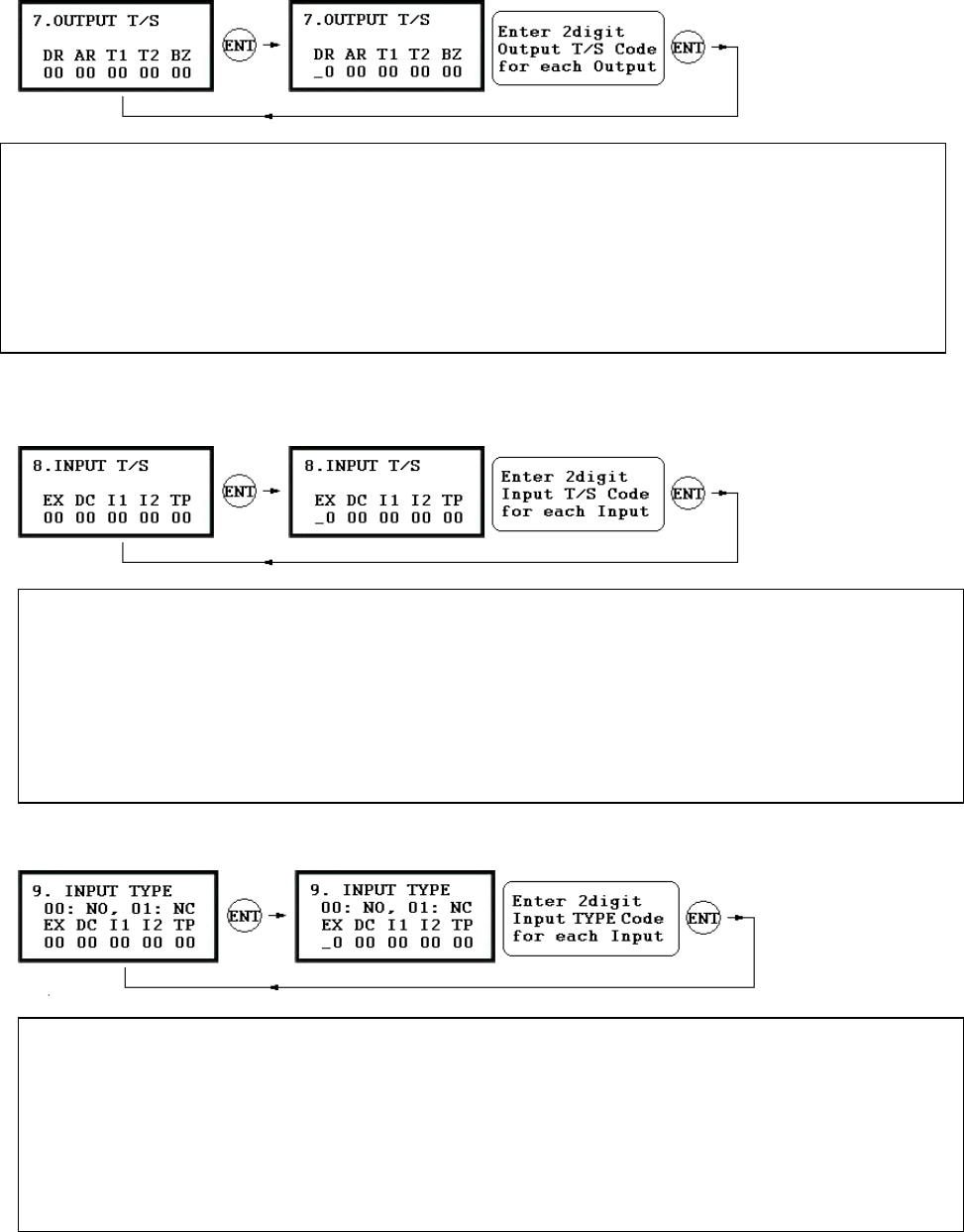
9.6.7 OUTPUT TIME SCHEDULE SETTING
9.6.8 INPUT TIME SCHEDULE SETTING
.6.9 I NG
Outputs. This setting i to o me I
Press <ENT> key to l
AR: Alarm Relay Output T
T1: TTL#1 Output T/S Cod
TTL#2 Output T/S Code
BZ: Buzzer Output T/S Code
. You can ☞link a T/S Code to each Output. The default T/S Code is “00” which means no T/S is applied to the
s very useful when you want pen the door for a Ti nterval.
ink a T/S Code to the Output then enter 2digit T/S Code for each Output.
DR: Door Relay Output T/S Code
/S Code
e
T2:
NPUT TYPE SETTI
DC: Door Contact Sensor Input T/S Code
I1: Aux Input#1 T/S Code
I2: Aux Input#2 T/S Code
TP: Tamper Switch Input T/S Code
. You can ☞link a T/S Code to each Input. The default T/S Code is “00” which means no T/S is applied to the
Inputs. This setting is very useful when you want to activate PIR sensor input for a Time Interval.
Press <ENT> key to link a T/S Code to the Input then enter 2digit T/S Code for each Input.
EX: EXIT Button Input T/S Code
9
EX: EXIT Button Input type
DC: Door Contact Sensor Input type
I1: Aux Input#1 type
. You can ☞program input type(00: NO, 01: NC) to each Input. The default input type is “00” which means inpu
t
is NO type.
Press <ENT> key then enter 2digit Code for each Input.
I2: Aux Input#2 type
TP: Tamper Switch is “00” because it is internal device.
52
9.7 F7 SETUP MENU
53
* Default Output Setting for Input Circumstance
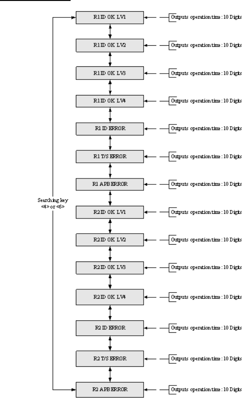
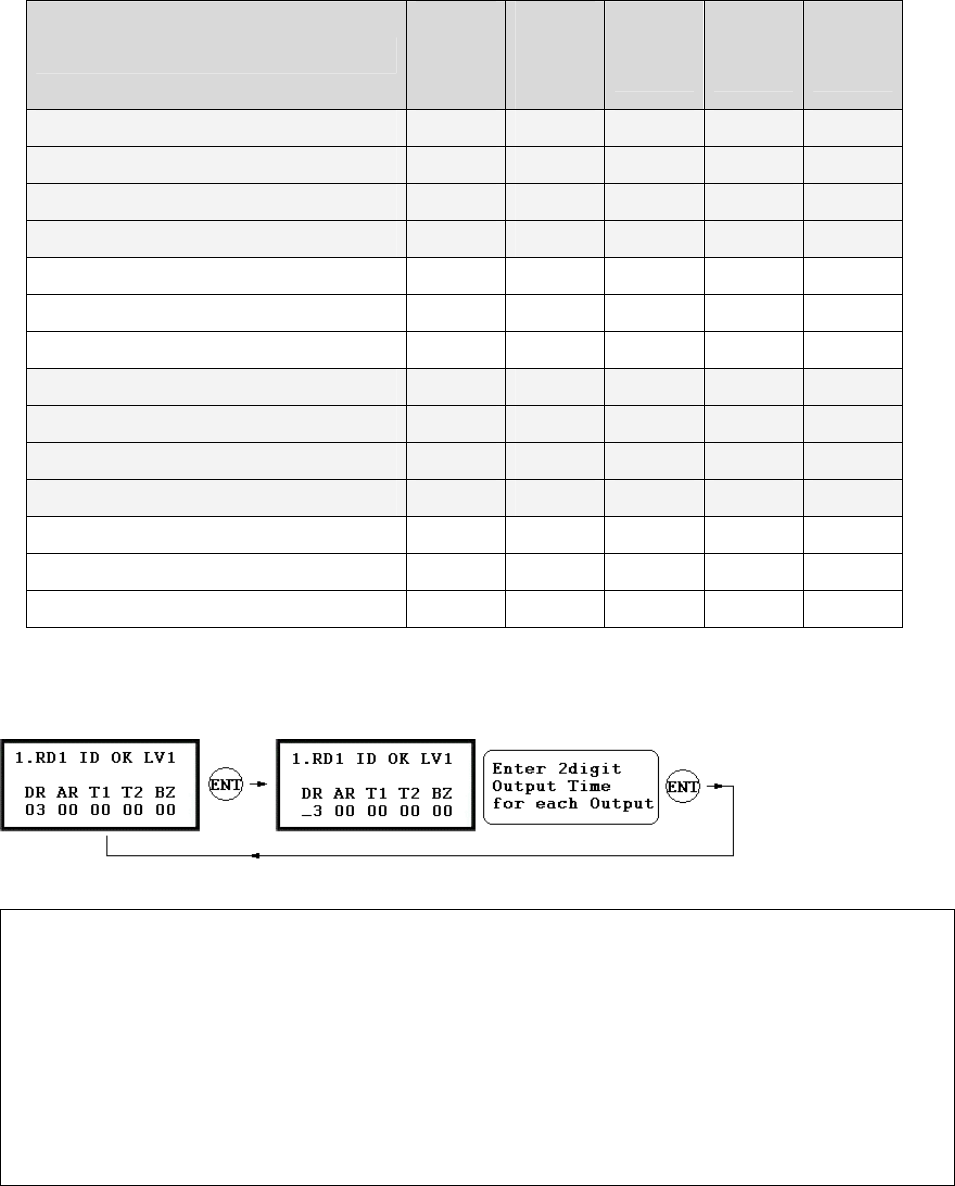
9.7.1 OUTPUT SETTING FOR READER#1 ID OK LEVEL 1
Output Time setting from 9.7.2 to 9.7.14 is the same as 9.7.1 RD1 ID OK LV1 Output setting.
OUTPUT
Door
Relay
(DR)
Alarm
Relay
(AR)
TTL#1
(T1)
TTL#2
(T2)
Buzzer
(BZ)
[1] Reader#1 ID OK LV1 03 00 00 00 00
[2] Reader#1 ID OK LV2 05 00 00 00 00
[3] Reader#1 ID OK LV3 05 00 00 00 00
[4] Reader#1 ID OK LV4 05 00 00 00 00
[5] Reader#1 ID Error 00 03 00 00 00
[6] Reader#1 T/S Error 00 03 00 00 00
[7] Reader#1 APB Error 00 03 00 00 00
[8] Reader#2 ID OK LV1 03 00 00 00 00
[9] Reader#2 ID OK LV2 05 00 00 00 00
[10] Reader#2 ID OK LV3 05 00 00 00 00
[11] Reader#2 ID OK LV4 05 00 00 00 00
[12] Reader#2 ID Error 00 03 00 00 00
[13] Reader#2 T/S Error 00 03 00 00 00
[14] Reader#2 APB Error 00 03 00 00 00
. You can program ☞OUTPUT activating time when the user ID is granted the access from the Reader#1. The
value put here is value x second when the Time Unit set to 1 second and value/10 second when the Time Uni
t
set to 0.1 sec. This Output Time is applied for the users registered with Level#1 output.
You can set the time from 00 to 98 seconds (0.0 to 9.8 seconds if Time Unit set to 0.1 sec.) and if you put the
value “99”, the Output will activate forever until you reset the Output.
Press <4> or <6> key to select Input Sources then press <ENT> key to program the Output time.
DR: Door Relay Output Time
AR: Alarm Relay Output Time
T1: TTL#1 Output Time
T2: TTL#2 Output Time
BZ
:
B
u
zz
e
r
Output
Tim
e
54
9.7.2 OUTPUT SETTING FOR READER#1 ID OK LEVEL 2
This Output Time is applied for the users registered wi Level put
9.7.3 OUTPUT SETTING FOR READER#1 ID OK LEVEL 3
r the users registere th Level utput.
9.7.4 OUTPUT SETTING FOR READER#1 ID OK LEVEL 4
r the users registere th Level utput.
9.7.5 OUTPUT SETTING FOR READER#1 ID ERROR
This Output Time is applied if the user is not registered to Reader#1.
9.7.6 R READER#1 ERRO
he user is T/S erro eader#
9.7.7 OUTPUT SETTING FOR READER#1 APB ERROR
e user is APB erro Reader#
9.7.8 OUTPUT SETTING FOR READER#2 ID OK LEVEL 1
r the users registere th Level utput.
9.7.9 OUTPUT SETTING FOR READER#2 ID OK LEVEL 2
This Output Time is applied for the users registered with Level#2 output.
This Output Time is applied for the users registered with Level#3 output.
9.7.11 OUTPUT SETTING FOR READER#2 ID OK LEVEL 4
This Output Time is applied for the users registered with Level#4 output.
9.7.12 OUTPUT SETTING FOR READER#2 ID ERROR
.7.13
T
.7.14
T ser is APB error to Reader#2.
th #2 out .
This Output Time is applied fo d wi #3 o
This Output Time is applied fo d wi #4 o
OUTPUT SETTING FO T/S R
This Output Time is applied if t r to R 1.
This Output Time is applied if th r to 1.
This Output Time is applied fo d wi #1 o
9.7.10 OUTPUT SETTING FOR READER#2 ID OK LEVEL 3
This Output Time is applied if the user is not registered to Reader#2.
OUTPUT SETTING FOR READER#2 T/S ERROR
his Output Time is applied if the user is T/S error to Reader#2.
OUTPUT SETTING FOR READER#2 APB ERROR
his Output Time is applied if the u
9
9
55
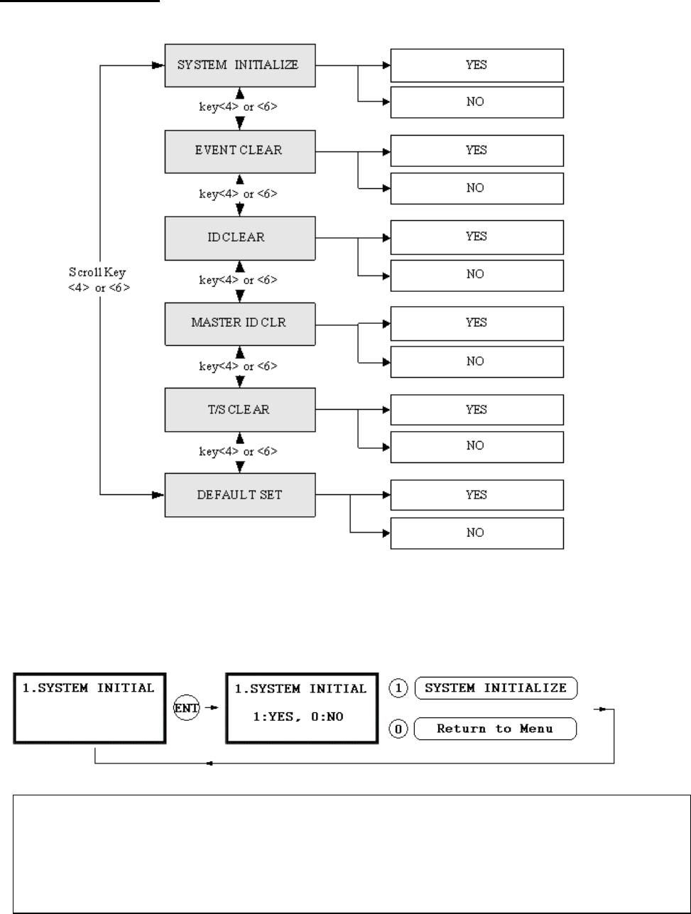
9.8 F8 SETUP MENU
9.8.1 SYSTEM INITIALIZE
☞. This operation will initialize the GE314. Press <ENT> key, if an initialization is needed (First time installation
or resetting in the event of a malfunction).
CAUTION: Initializing will erase all stored data in the memory.
☞. Press the <1> key to initialize or <0> key to cancel the operation.
☞. The “WAIT..”message appears while the system is being initialized.
After the initialization, GE314 will return to the Setup menu.
56
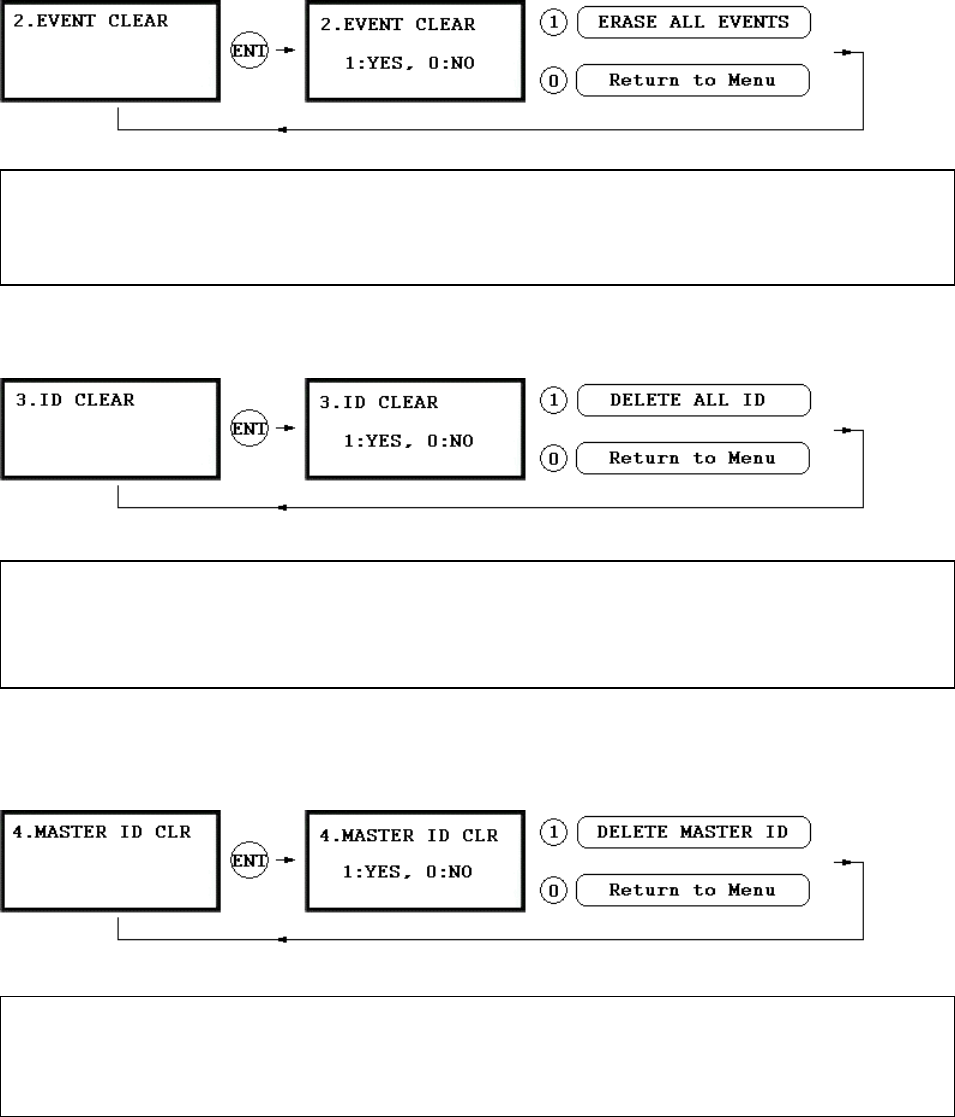
9.8.2 EVENT CLEAR
9.8.3 ID CLEAR
9.8.4 MASTER ID CLEAR
☞. When you want to delete all User IDs (Card IDs), you can clear all User IDs from the memory. Press <ENT>
key, then press the <1> key to clear all User IDs or <0> key to cancel the operation.
CAUTION: Before clearing all User IDs, make sure that the registered User ID is no longer used otherwise
you may lose all registered User IDs.
☞. When the event memory is full or when you want to change ID COUNT, you can clear the event memory i
n
this menu. Press <ENT> key then press <1> key to clear event memory or <0> key to cancel the operation.
CAUTION: Before
y
ou clear the events, make sure that the stored events is not necessar
y
to upload to the
host PC otherwise you may lose important data.
☞. When you want to delete all Master IDs, you can clear all Master IDs from the memory. Press <ENT> key,
then press the <1> key to clear all Master IDs or <0> key to cancel the operation.
CAUTION: Before clearin
g
all Master IDs, make sure that the re
g
istered Master ID is no lon
g
er used
otherwise you may lose all registered Master IDs.
57
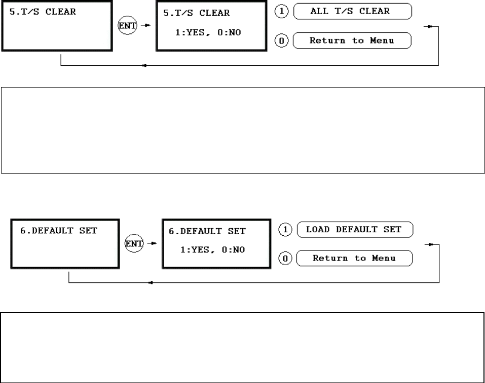
9.8.5 TIME SCHEDULE CLEAR
9.8.6 DEFAULT SETTING
☞. When you want to delete all Time Schedules (01~10), all Holiday schedules(01~10), Holiday code, Reader#1
Mode T/S code and Reader#1 Mode T/S code, you can clear them from the memory. Press <ENT> key a
press the <1> key to clear all T/S or <0> key to cancel the operation.
CAUTION: Before you clear all T/S, make sure that the stored T/S is no longer used, otherwise
y
ou ma
y
lose all stored T/S in the memory.
☞. When you want to delete all Default setting value, you can clear them from the memory. Press <ENT> key an
d
press the T/S or <0> key to cancel the operation.
CAUTION: Before
<1> key to reload all default setting value clear all
y
ou clear all Default settin
g
value(Reader mode, Board ID etc..), make sure that the
stored system setting value is no longer used, otherwise you may lose all stored system setting value in
the memory.
n
d
58
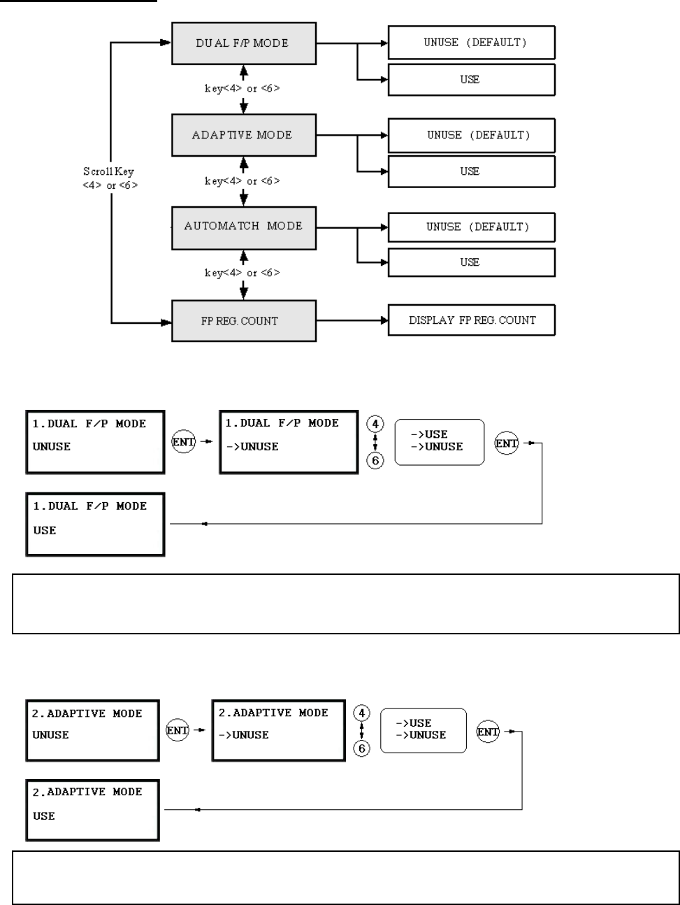
9.9 F9 SETUP MENU
9.9.1 DUAL FINGERPRINT MODE
.9.2 ADAPTIVE MODE
FINGERPRINT MODE, you can register two fingerprints for one user ID. Default is UNUSE.
Fingerprint Mode is higher False Acceptance Rate (FAR) measured.
. ☞In DUAL
But Dual
9
.☞ In ADAPTIVE MODE, scanning quality is better than normal mode and also it checks latent finger..
But scanning speed is longer than normal mode. Default is USE.
59
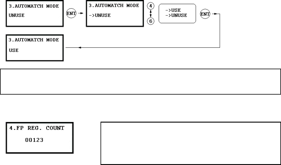
9.9.3 AUTOMATCH MODE
9.9.4 FP REG. COUNT
. ☞Automatch Mode is an IDENTIFICATION MODE, you can use 1:N Identification. You can Identify ID b
y
only putting finger to the scanner. Automatic Touch Sensor is optional purchase.
☞. This menu displays the total number of registered user ID. I
t
automatically counts when you register or delete er IDs. The LCD
shows total 123 user IDs registered in the memory.
. Total number of user IDs is 1,000 user IDs (standard) or optional
2,000/4,000 user IDs can be stored in the unit.
us
☞
60

APPENDIX
A. THE RELATION BETWEEN INPUT AND OUTPUT (DEFAULT)
* Default Output Setting for Input Sources
* Index No. [1] ~ [6]:
The value indicates operation time (second) of each output for the input signal.
* Index No. [7]:
The value indicates time schedule code (index) that each output operation has to
be applied.
* Index No. [8]:
The value indicates the time schedule code (index) that each input #1(Exit
button) ~#5 operation has to be applied.
* Index No. [9]:
The value indicates the type of each input #1(Exit button) ~#5 operation.
The “00” is NO(Normal Open) type.
The “01” is NC(Normal Close) type.
OUTPUT
INPUT
Door
Relay
(DR)
Alarm
Relay
(AR)
TTL#1
(T1)
TTL#2
(T2)
Buzzer
(BZ)
[1] EXIT BUTTON 03 00 00 00 00
2] DOOR CONTACT 00 99 00 [00 00
[3] AUX Input #1 00 00 00 00 00
[4] AUX Input #2 00 00 00 00 00
[5] TAMPER ALARM 00 99 99 99 99
[6] DURESS ALARM 00 00 00 00 00
00 00 00 00 00
00 00 00 00 00
[7] OUTPUT TIME SCHEDULE
[8] INPUT TIME SCHEDULE
[8] INPUT TYPE 0 00 00 00 00 0
61

* Default Output Setting for Input Circumstance
14]:
* Index No. [1] ~ [
The value indicates operation time (second) of each output for the input signal.
OUTPUT
INPUT Relay Relay (T1)
Door
(DR)
Alarm
(AR)
TTL#1 TTL#2
(T2)
Buzzer
(BZ)
[1] Reader#1 ID OK LV1 03 00 00 00 00
[2] Reader#1 ID OK LV2 05 00
05 00
05 00
[5] Reader#1 ID Error 00 03 00 00 00
[6] Reader#1 T/S Error 00 03 00 00 00
[7] Reader#1 APB Error 00 03 00 00 00
[8] Reader#2 ID OK LV1 03 00 00 00 00
[9] Reader#2 ID OK LV2 05 00 00 00 00
[10] Reader#2 ID OK LV3 05 00 00 00 00
[11] Reader#2 ID OK LV4 05 00 00 00 00
[12] Reader#2 ID Error 00 03 00 00 00
[13] Reader#2 T/S Error 00 03 00 00 00
00 00 00
[3] Reader#1 ID OK LV3 00 00 00
[4] Reader#1 ID OK LV4 00 00 00
[1 00 03 00 00 00 4] Reader#2 APB Error
62
B
☞ A ed after batch-downloading IDs from PC.
. TROUBLE SHOOTING
valid card became unregister
ause Wrong procedure during pon ct.
tive of evice.
tion 1. Check BAT connection S/
You have to short the itialize b
C download or a com ent defe
Solution 1. The card ID might be registered only to the controller and not registered in the PC. During the process
314 first erase the ID memory of the unit, therefore if the IDs from the PC
didn’
2. Check whether the card ID is registered in the PC.
3. If not, please register the number and try downloading again.
4. If the trouble remains after the procedure above, contact a designated service center.
of downloading IDs, GE
t contain the card ID, this can happen.
☞ It doesn’t enter the Setup Mode after entering the Master ID “00000000”.
Cause The Master ID might have been changed or components are defective.
Solution 1. Try changing the Master ID through the application S/W (It’ll be changed to “00000000”).
2. When it is not feasible, initialize the unit as following:
After the all installation and connections are completed, press and hold the Initialize button and put the
power (+12V DC) to GE314. The LCD will first display “Initialize OK? 0:No 1:Yes”. Press <1> key
if you want to initialize the system. After all Initialization process is completed, the system is operating
on normal mode and the LCD displays “GE Security, GE314 [F1], Date Time”.
3. If the trouble remains after the procedure above, contact a designated service center.
☞ When the power off and on after the time setting, the LCD displays “00/00 00:00:01”.
Cause Of that user mistake, or the system is defec the d
Solu W.
S/W, and system in efore system installation.
Figure: SWITCH SETTING Figure: SWITCH LOCATION
2. If the trouble remains after checking the above, contact a designated service center.
63

☞ No problem with accessing by card, but cannot access with the PIN input.
Cause An error in Setup or possible component defect.
Solution 1. Check whether a beep sound is generated when you press a key.
When a beep sound is generated, the problem may be an error in setup. Proceed like followings:
000” default) to enter the Setup mode.
- [LANGUAGE] will appear on the LCD, then use the key <6> to choose [RD1_PIN_INPUT] and
SE’ as wanted.
2. When th sound or already enabled Key-in functions, contact a designated service center.
- Enter the Master ID (“00000
- Press <F2> key.
select ‘U
ere is no beep
ime out erro
up mode, it is programmed to do so when there is no key-in or reading card within 60
☞ The Setup mode suddenly goes back to the Normal operating mode.
Cause T r
Solution In the Set seconds.
☞ Keeps making buzzer sound: “beep~ beep ~ beep” or “beeeeeeeep~~~~”.
olution 1. Check the door status. It occurs in case that the door is o
open time.
Check the door contact sensor type: it should be NO type.
Check in [7. OUTPUT T/S] of F6, the ten Ti
schedule code is set between 01 up to 10 and if the p
If it is set to unintended value, change it to “00” ( Programmab
4. Check in Tamper switch of GE314.
Cause Error in Installation, Door status or Internal circuits.
Spened over 3sec(Default) after the proper door
2.
3. me schedule code (01~10) value of output T/S. If the time
resent time is included in the schedule.
le via PC software)
5. If the trouble remains after checking the above, contact a designated service center.
64

☞ “SCHEDULE ERROR” message shows when RFID card is read.
Cause Error in RFID card registration, time schedule setting or the system itself.
Solution 1. If it was a properly operating unit before, there has been an electric shock that damaged the internal
2. C ion.
* R ng the following points.
-In
schedul y the time schedule code(1~10) in the registration of the user ID.
3. Use software for time schedule setting in case it is connected to PC as the software manual.
4. If the trouble remains after checking the above, contact a designated service center.
memory and data. Please initialize the unit as instructed in the manual.
heck if ID information has been put in incorrectly during its registrat
egister ID again checki
order to restrict access of the ID user for specific time zone as instructed in the manual, register time
e in advance and appl
- In order to allow the user to access at all times, put in “00”.
☞ “ACCESS DOOR ERR” message shows when the RF ID card is read.
Cause Incorrect user setting or false of internal circuit.
Solution 1. If it was a properly operating unit before, there has been an electric shock that damaged the internal
during its registration.
ontroller has two reader ports, define “RD” – door for the user to be allowed to access
nly: “2”, Reader 1 & 2 both: “0 or 3”)
t reader1. If it is read
R” message shows up.
3. If the trouble remains after checking the above, contact a designated service center.
memory and data. Please initialize the unit as instructed in the manual.
2. Check if ID information has been put in incorrectly
* Register ID again and check the following points:
- Since the c
(Reader1(Bilt-in reader) only: “1”, Reader 2(Extra reader) o
- If RD is set as “1”, only when the card is read at Reader 1, the door opens but not at Reader2. If it is
read at Reader 2, “ACCESS DOOR ERROR” message shows up.
- If RD is set as “2”, only when the card is read at reader 2, the door opens but not a
at reader 1, “ACCESS DOOR ERRO
- If RD is set as “0 or 3”, reader 1 & 2 both open each door.
65
☞ The controller does not communicate with the Host-PC.
Cause A defective cable is used, errors in wiring, an error in setting COMM ID of the controller, or damage on
the communication port (either on PC side or on the controller side).
1. Please check the settings of the application S/W and the controller.
- Check if the controller’s COMM ID is listed on the application S/W.
ntrollers are installed - Set the different COMM ID when two or more co
- Check if the communication speed (9600bps def
- Make sure that the PC’s COM port is set correctly on the S/W.
- The parameters at the S/W should be set as following:
Parity bit : NONE
Data bit : 8bit
Stop bit : 1bit
2. Check the line connection for communication.
RS232 RS485 (mono)
Solution
.
ault) is the same as the setting on the S/W.
GE313 PC GE314
RS485/232
Converter PC
RX TX RTX(-) RTX(-)
TX RX RTX(+) RTX(+)
GND GND
The RS232 cable from
the converter
RS485(Multi Drop)
GE314 GE314 RS485/232
Converter PC
RX(-) RX(-) TX(-)
RX(+) RX(+) TX(+)
The RS232 cable from
the converter
3. In case of setting RS485 communication, we recommend to use line-end resistors of 120 Ohm
between the RTX (+) and RTX (-) lines. Apply the same resistors to the converter RS485 lines.
Consult a service center or an electric technician if you are no
4. When a multi-drop communication doesn’t work, test one
5. If the trouble remains after the procedure above, contact a
t sure how to do it.
-by-one communication first.
designated service center.
66

FCC REQUIREMENTS PART 15
Caution: Any ch y the
manufacturer fo ent.
NOTE: This device c f the FCC Rules.
Operation is subjec
1. This device m
2. This device m erference that may cause undesired operation.
This equipment has been test foun comply with e lim s A Digital Device, pursuant to Part 15
of the FCC Rules. These l desi to this ent ge , and can radiate frequency energy
and, if not installed and n acc nce w instru y ca ce to radio
communications.
However, there is no guaran at interference wi cur in a r installatio uipment does cause
harmful interference to radi levision ion, which can be determined by turning the radio or television off and
on, the user is encouraged t corre one or more of the following measures.
1. Reorient or relocate the receiving antenna.
2. Increase the separation between the equipment and re
3. Connect the equipment ut ther
4. Consult the dealer or an technician for help.
FCC REGISTRATION INFORMATION
anges or modifications in construction of this device which are not expressly approved b
r compliance could void the user's authority to operate the equipm
omplies with Part 15 o
t to the following two conditions;
ay not cause harmful interference, and
ust accept any interference received, including int
ed and
imits are
d to
gned
th
equipm
its for a Clas
snerates, use
c a
radio
used i orda ith the tions, m use harmful interferen
tee th ll not oc particula n. If this eq
o or te
o try to
recept
ct interference by
ceiver.
into an o
experienced radio/TV
let on ano circuit.
67

WARRANTY AND SERVICE
GE314 warranty is 1 years from the shipping date;
Authorization) number. The customer is to
returns must have an RMA (Return Material
provide a description of the specific problem. The customer is
IN THE UNITED STATES
to include serial numbers, formats, and model numbers with the items to be returned.
1
Fax.: 310-782-8292
RF LOGICS Inc. Service Center
370 Amapola Ave.#106, Torrance, CA9050
Tel.: 310-782-8383
E-mail: rflogics@rflogics.com
Web-site: www.rflogics.com
OUTSIDE OF THE UNITED STATES
ID TECK CO., LTD. Service Center
5F Ace Techno Tower B/D. gu,
E-mail: webmaster@idteck.com
Web-site: www.idteck.com
Technical Support(in korea)
684-1 Deungchon-dong, Gangsuh-
SEOUL 157-030, KOREA
Tel.: +82-(2)-2659-0055
Fax.: +82-(2)-2659-0086
E-mail : techsupport@idteck.com
Hotline: +82-16-604-8965 (Customer support)
+82-17-340-4170(R&D)
Please use the original container, or pack the unit(s) in a sturdy carton with sufficient packing to
prevent damage, include the following information:
1. A proof-of-purchase indicating model number and date of purchase.
2. Bill-to address
3. Ship-to address
4. Number and description of units shipped.
5. Name and telephone number of person to contact.
6. Reason for return and description of the problem.
NOTE: Damage occurring during shipment is deemed the responsibility of the carrier, and claims
should be made directly to the carrier.
68

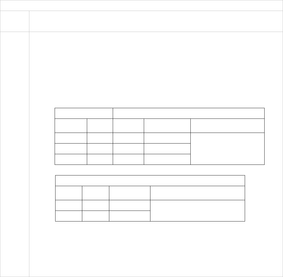
RMA REQUEST FORM & A/S REQUEST FORM
ID
5F, Ace Techno Tower B
TEL : +82-2-2659-0055, FAX ; +82-2-2659-0086, www.idteck.com
RMA REQUEST FORM
RMA REQUEST FORM : ORIGINAL
TECK Co., LTd
/D, 684-1, Deungchon Dong, Gangsuh Gu, Seoul, Korea 157-030
RMA No. & Date :
inal Invoice No. & Date : OrigA Control Center
Se
RM
5F, Ace Techno Tower B/D 684-1,
Deungchon-Dong, Kangsuh-Gu
Se
nd To
oul, Korea, 157-030
Sa
Requested From :
les Person In Charge
Shipping Port :
Ai Departure Date :
r / Vessel :
Model Serial Number N Error Check Box by shipper
O RS 232 Com. □
Input/Output □
Power □
Keypad □
Card Reading □
RS 422 Com □
1 Engineer
Comment Others □ :
RS 232 Com. □
Input/Output □
Power □
Keypad □
Card Reading □
RS 422 Com □
2 Engineer
Comment Others □ :
RS 232 Com. □
Input/Output □
Power □
Keypad □
Card Reading □
RS 422 Com □
3 Engineer
Comment Others □ :
RS 232 Com. □
Input/Output □
Power □
Keypad □
Card Reading □
RS 422 Com □
4 Engineer
Comment Others
RS 232 Com
□ :
. □
Input/Output □
Power □
Keypad □
Card Reading □
RS 422 Com □
5 Engineer
Comment Others □ :
Manufacture’s Verification
oduct Defective : InstallatioPr
Us
Co
n Error :
er’s Misuse :
Connection Error :
Others : mmunication Error :
Packing Details
Di No. of Units
Ne . of Boxes
mension(L:W:H) :
t & Gross Weight : No
Requested By Received By
Buyer’s Signature IDTECK’s Signature
69

RMA
ID TECK Co., LTd
ong, Gangsuh Gu, Seoul, Korea 157-030
, www.idteck.com
RMA REQUEST FORM
REQUEST FORM : SAMPLE
5F, Ace Techno Tower B/D, 684-1, Deungchon D
TEL : +82-2-2659-00 5, FAX ; +82-2-2659-00865
RMA No. & Date : We send this No. , when you want.
Date : 00-00-0-000 / 1990.01.01Original Invoice No. &
Send To
RMA Control Center
5F, Ace Techno Tower B/D 684-1
on-Dong, Kangsuh-Gu
,
Deungch
Seoul, Korea, 157-030
Sales Person In Charge
Karina Kwak ABC Company,… address….
Requested From :
Mr. Luis Castro
Tokyo, Japan
Shipping Port : Narita
Air / Vessel : Air
Departure
Date : 2003, 11. 25
NO Model Serial Number r C eck Box by shipper Erro h
505R XXXXXXXXX
Keypad ▣ RS 42
1 Engineer
C
Write problem to be
detailed. omment Others □ :
others RS 232 Com. □ Power □
Ke
Card Reading □
Input/Output □ ypad □ RS 422 Com □
omment Others □ :
RS 232 Com. □
Input/Output □
Po
Ke
wer □
ypad □
Card Reading □
RS 422 Com □
3 E
C
ngineer
omment Others □ :
RS 232 Com. □
Input/Output □
Po
Ke
wer □
ypad □
Card Reading □
RS 422 Com □
4 E
C
ngineer
omment Others □ :
RS 232 Com. □
□ Input/Output
Po
Key RS 422 Com
wer □
pad □
Card Reading □
□
ngineer
Comment Others □ :
Manufacture’s Verification
Product Defective :
User’s Misuse :
Communication Error : Others :
Installati
Connecti
on Error :
on Error :
Packing Details
Dimension(L:W:H) : 30 * 25 * 80 No. of Units 20
et & Gross Weight : 10Kg No. of Boxes 2 NRequested By Received By
XXXXXXXX
XXX X
RS 232 Com. □
Input/Output □
Power ▣ Card Reading ▣
2 Com □
2 Engineer
C
5 E
Buyer’s Signature IDTECK’s Signature
70
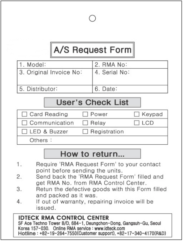
A/S REQUEST FORM : ORIGINAL
71
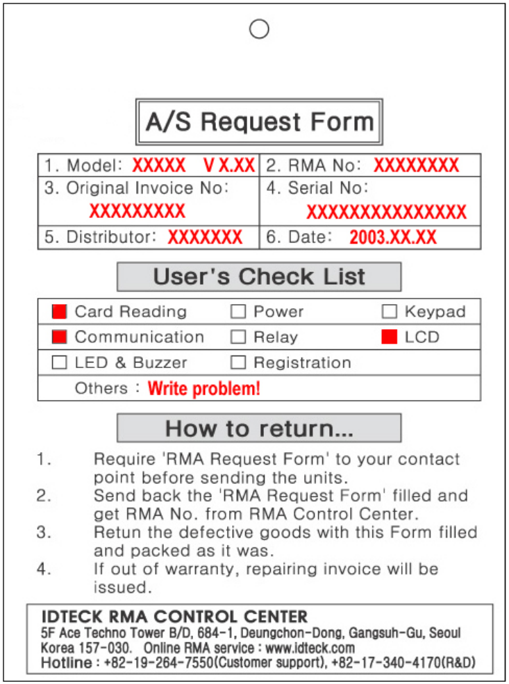
A/S REQUEST FORM : SAMPLE
72

MEMO
73

The specification contained in this manual are subject to change without notice at any time.
5F, Ace Techno Tower B/D, 684-1, Deungchon-Dong,
Fax : (82) 2 2659-0086
E-mail : webmaster@idteck.com
Gangsuh-Gu, Seoul, Korea 157-030
Tel : (82) 2 2659-0055
MAR. 2005 Copyright ©2004 IDTECK Co., Ltd.