ID Teck Co LX006 Fingerprint Recognition Proximity Reader User Manual
ID-Teck Co Ltd Fingerprint Recognition Proximity Reader Users Manual
UserManual.wiki
>
ID Teck Co
>
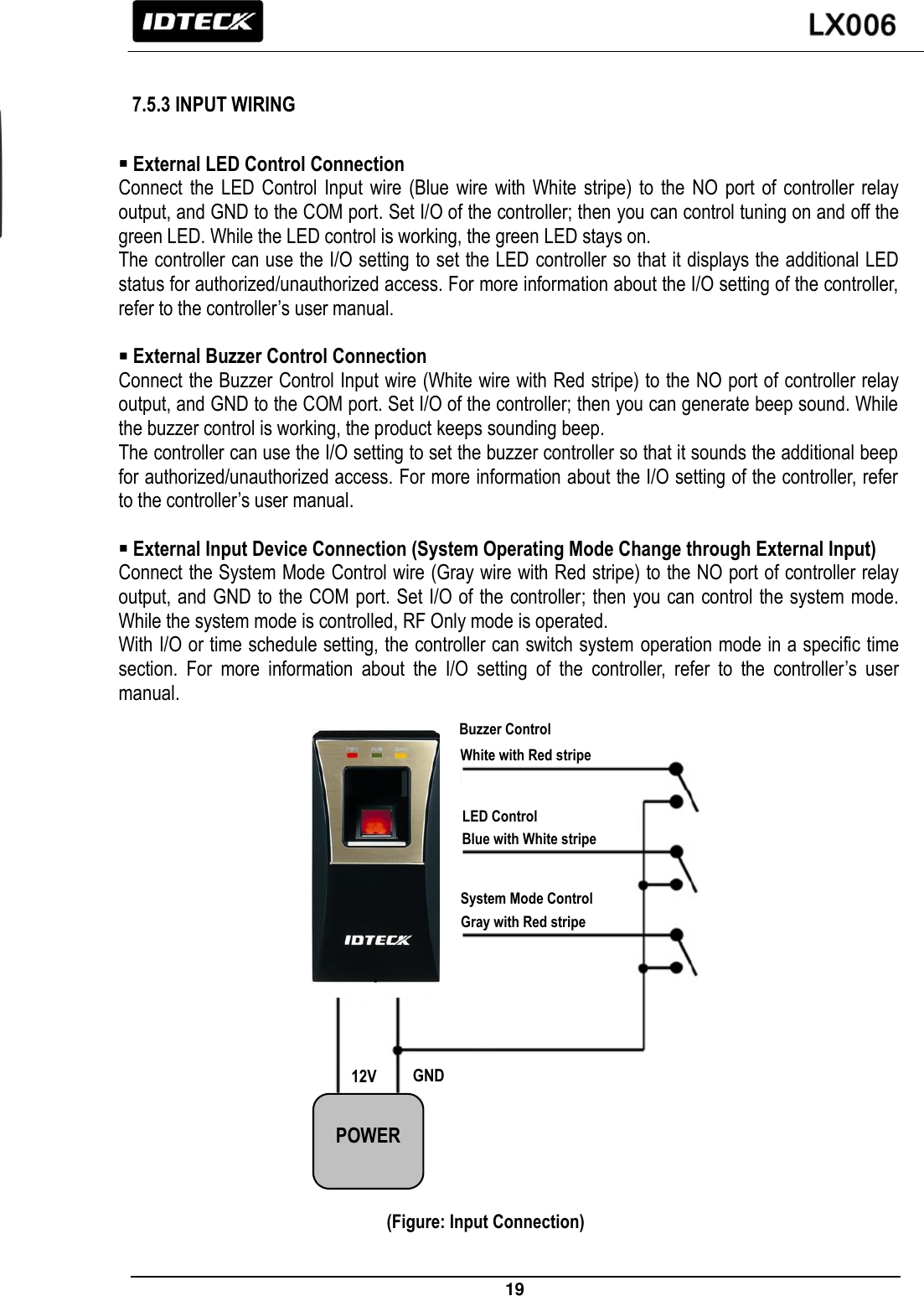
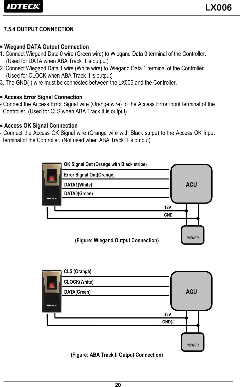
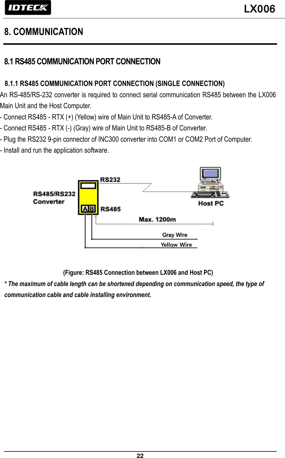
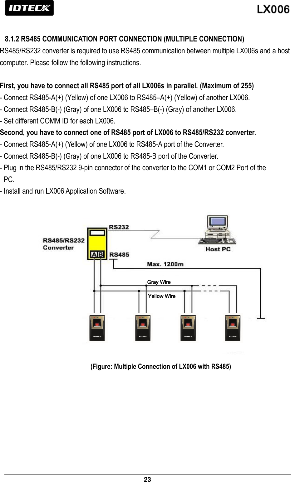
LX006 User Manual
User Manual
Navigation menu
Upload a User Manual
Namespaces
Wiki Guide
HTML
PDF
Info
Views
User Manual
Discussion / Help
Navigation