ID Teck Co LX006 Fingerprint Recognition Proximity Reader User Manual
ID-Teck Co Ltd Fingerprint Recognition Proximity Reader Users Manual
User Manual
User’s Manual
LX006
Fingerprint Identification
Proximity Reader

2
TABLE OF CONTENTS
1. IMPORTANT SAFETY INSTRUCTIONS .......................................................................................................................... 4
2. FEATURES ....................................................................................................................................................................... 5
3. SPECIFICATION .............................................................................................................................................................. 7
4. IDENTIFYNG SUPPLIED PARTS .................................................................................................................................... 9
5. PRODUCT EXPLANATION ............................................................................................................................................ 10
5.1 PANEL LAYOUT .................................................................................................................................................. 10
5.2 CONNECTION LAYOUT...................................................................................................................................... 10
5.3 COLOR CODED & WIRING TABLE .................................................................................................................... 11
6. INSTALLATION TIPS & CHECK POINTS ...................................................................................................................... 12
6.1 CHECK POINTS BEFORE INSTALLATION ........................................................................................................ 12
6.1.1 CABLE SELECTION ................................................................................................................................ 12
6.1.2 RECOMMENDED CABLE TYPE AND PERMISSIBLE LENGTH OF CABLE ......................................... 12
6.1.3 READER CONNECTION ......................................................................................................................... 12
6.2 CHECK POINTS DURING INSTALLATION ......................................................................................................... 13
6.2.1 TERMINATION RESISTOR ..................................................................................................................... 13
6.2.2 HOW TO CONNECT TERMINATION RESISTORS................................................................................. 14
6.2.3 GROUNDING SYSTEM FOR COMMUNICATION CABLE ...................................................................... 14
7. INSTALLATION OF THE PRODUCT .............................................................................................................................. 15
7.1 WALL MOUNT DRAWING ................................................................................................................................... 15
7.2 INSTALLATION OF WALL MOUNT ..................................................................................................................... 15
7.3 SYSTEM INITIALIZATION ................................................................................................................................... 16
7.4 COMMUNICATION ID SETTING ......................................................................................................................... 17
7.5 WIRING ............................................................................................................................................................... 18
7.5.1 WIRING LAYOUT ..................................................................................................................................... 18
7.5.2 POWER WIRING ..................................................................................................................................... 18
7.5.3 INPUT WIRING ...................................................................................................................................... 19
7.5.4 OUTPUT CONNECTION ......................................................................................................................... 20
7.5.5 EXTERNAL READER CONNECTION ..................................................................................................... 21
8. COMMUNICATION ......................................................................................................................................................... 22
8.1 RS232 COMMUNICATION PORT CONNECTION ...................
8.2. RS485 COMMUNICATION PORT CONNECTION ............................................................................................. 22
8.2.1 RS485 COMMUNICATION PORT CONNECTION (SINGLE CONNECTION) ........................................ 22
8.2.2 RS485 COMMUNICATION PORT CONNECTION (MULTIPLE CONNECTION) .................................... 23
8.3 TCP/IP COMMUNICATION PORT CONNECTION ............................................................................................. 24
9. BASIC SETTING ............................................................................................................................................................ 25
............................................................................................. 22

3
9.1 INITIALIZATION OF LX006 ................................................................................................................................. 25
9.2 COMMUNICATION ID SETTING ......................................................................................................................... 25
10. OPERATION MODE ..................................................................................................................................................... 26
10.1 MASTER CARD REGISTRATION MODE ......................................................................................................... 26
10.1.1 MASTER CARD REGISTRATION ......................................................................................................... 26
10.1.2 MASTER CARD CHANGE..................................................................................................................... 26
10.1.3 MASTER CARD FUNCTION. ................................................................................................................ 26
10.2 REGISTRATION / DELETION MODE ............................................................................................................... 26
10.2.1 REGISTRATION MODE FUNCTION ..................................................................................................... 26
10.2.2 USER CARD REGISTRATION .............................................................................................................. 26
10.2.3 USER CARD DELETION ....................................................................................................................... 28
10.3 READER MODE ................................................................................................................................................ 28
10.3.1 READER MODE FUNCTION. ................................................................................................................ 28
10.3.2 AUTHORIZATION .................................................................................................................................. 28
10.4 READER INDICATOR ....................................................................................................................................... 29
10.5 DEFAULT SETTINGS ........................................................................................................................................ 30
11. OUTPUT FORMAT ....................................................................................................................................................... 31
11.1 WIEGAND OUTPUT (DEFAULT) ....................................................................................................................... 31
11.2 ABA TRACK Ⅱ (SELECTABLE USING THE SOFTWARE) .............................................................................. 31
11.3 OUTPUT MODE ................................................................................................................................................. 32
11.3.1 NORMAL OUTPUT MODE ..................................................................................................................... 32
11.3.2 EXTENSION OUTPUT MODE (SET BY APPLICATION SOFTWARE) ................................................. 33
12. APPENDIX .................................................................................................................................................................... 33
13. FCC REGISTRATION INFORMATION ......................................................................................................................... 37
14. WARRANTY POLICY AND LIMITATION OF LIABILITY ............................................................................................... 38
15. HOW TO MAKE RMA REQUEST (AFTER SALES SERVICE) .................................................................................... 39
4
1. IMPORTANT SAFETY INSTRUCTIONS
The description below is to keep user’s safety and prevent any product damage. Please fully read
these instruction and use the product properly.
Danger: This symbol indicates that incorrect handling of the product may result in
serious injury or death.
Warning: This symbol indicates that incorrect handling of the product may result
in injury or property damage.
- Only use the standard voltage (DC +12V/ 350mA).
(When supplying DC power to the device, we recommend that you use the adapter or SMPS that
come standard with the device.)
- If the product emits smoke or smells, stop using the product. Unplug the product from DC power
source and contact nearest service center.
- Do not install the product in humid, dust (metallic dust) and sooty place.
- Do not install the product in a place subject to high/ low temperature or high humidity
- Do not install the product with tools such as driver in hand when power has been supplied.
- Do not drop liquid like water and give a shock severely.
- Do not place magnetic objects near the product.
- Do not replace the wiring cables installed by experts.
- Do not use the product near direct sunlight and heating apparatus.
- If you want to relocate the installed product, turn power off and then move and reinstall it.
- Do not use the product near flammable spray or objects.
- Do not disassemble, repair or modify the product by yourself. If the product needs service or
repair, contact nearest service center.
- If liquid has been spilled on the product, unplug it and contact nearest service center.
- Do not clean the product with water. Clean gently with dry cloth or towel.
- Do not use chemicals such as benzene, thinner or acetone for cleaning.
Cautions about power
Cautions about installation
Cautions about usage
Cautions about cleaning

5
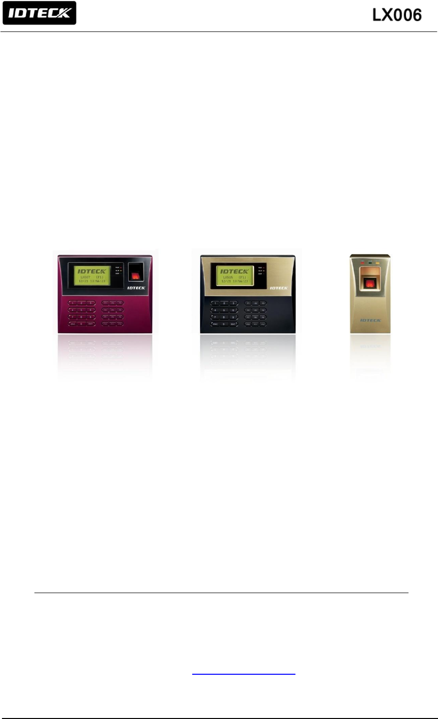
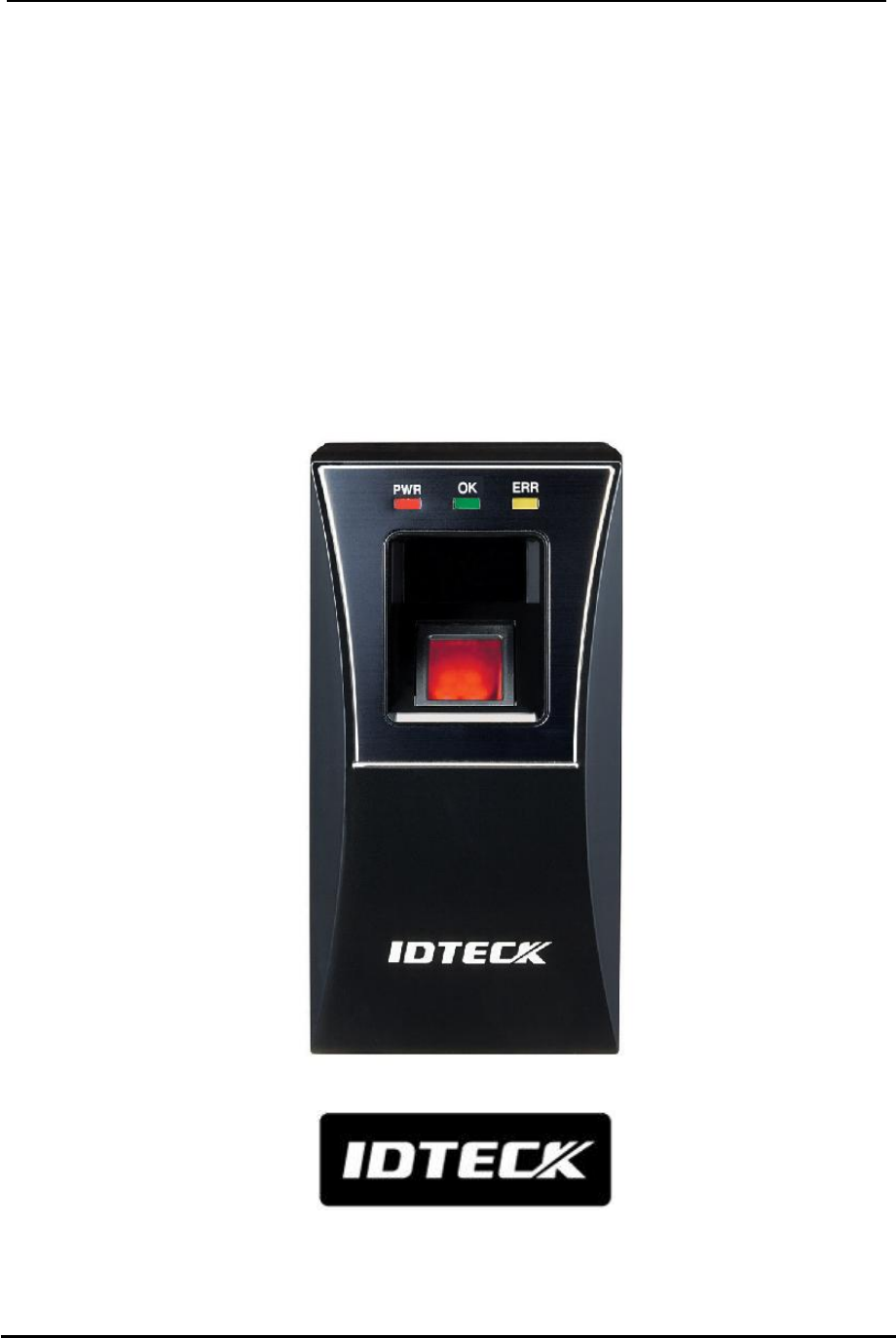
2. FEATURES
Fingerprint Recognition Proximity Reader
The LX006 is a Fingerprint and Proximity Reader compatible with existing proximity readers. The
LX006 has a built-in proximity reader and fingerprint module so that the access is only allowed when
the personal ID and fingerprint are authorized and this integrated system gives you high and reliable
security. The LX006 can register up to 200,000 User IDs and 1,000(default)/ 2,000(optional) /
4,000(optional) fingerprint users.
Easy Installation
LX006 can be easily installed on flat wall or the door frame.
1:1 Verification and 1:N Identification
User can select operation mode between 1:1 Verification and 1:N Identification for his convenience.
RF Only Mode and RF + FINGER Mode
The LX006 has two operation modes when it is operated as a reader.
- RF Only Mode
In the RF Only Mode, only card authorization is needed to grant access. If a card is authorized,
the corresponding card ID will be transmitted to the controller.
- RF + FINGER Mode
In the RF + Finger Mode, both card and fingerprint authorization is needed to grant access. If a
fingerprint is authorized, the corresponding card ID will be transmitted to the controller. If user’s
fingerprint is not registered, the mode is automatically working as ‘RF Only’
Network Communication
The LX006 can establish network communication via RS232 / RS485 and built in TCP/IP internal
module.

6
Card Number Output Format
When a fingerprint is authorized, the corresponding card number is transmitted to the controller via
26/34Bit (SR) Wiegand or ABA Track II according to the output type setting. It is set by application
software.
Card Number Input Format
The LX006 receives the card number from the external reader while the LX006 contains a built-in
proximity reader inside. The LX006 receives the card number in 8bit Burst or 26bit Wiegand or ABA
Track II format. It is set by application software.
User Registration and Deletion Using Master Card
User can register and delete IDs using Master Card without application software. Also the master
card is used to toggle the LX006 between the reader mode and the registration/deletion mode.
Firmware Upgrade
Use can upgrade firmware using application software
Voice Message Generation and Tamper switch
Voice Message notices users whether the LX006 is normally operating or not.
When someone has broken the installed LX006 by force, Temper Switch transmits corresponding
data to the Host PC to prevent theft.
Plenty of Application Software
There are plenty of application software for LX006, STARWATCH STANDARD, STARWATCH
ENTERPRISE, STARWATCH DUAL PRO I, II, STARWATCH iTDC PRO I, II, STARWATCH LX
ACCESS PRO II, STARWATCH ENROLLMENT PRO. If you use LX006 which has linked with the
third party access controller, visit IDTECK’s homepage (www.IDTECK.com) and download
STARWATCH FINGERPRINT ENROLLMENT PRO via download center.
7
3. SPECIFICATION
Model
LX006
CPU
32bit ARM9 and Dual 8bit Microprocessor
Memory
Fingerprint
Module
Program Memory
2MByte Flash Memory for 1000 Fingerprints
6MByte for 2000/4000 Fingerprints
Data Memory
8MByte SDRAM
Controller
Program Memory
128KByte Flash Memory
Data Memory
256KByte Flash Memory
32KByte SRAM
User ID
10,000 User IDs
Fingerprint User
1,000 / 2,000 / 4,000 Fingerprint Users
Reader Data Output Format
26Bit Wiegand,
ABA Track II
Reading Time (Card)
30ms
Verification / Identification Time
Less than 1sec. / Less than 2sec.
Power / Current
DC +12V / Max.290mA
External Reader Port
1 port
(26bit Wiegand, 4/8bit Burst for PIN,
ABA Track II)
Communication
RS232 / RS485 (Max.32ch)
TCP/IP
Baud Rate
57,600bps (Recommended)/9,600bps/
19,200bps/38,400bps (Selectable)
Input Port
3ports(LED, Buzzer, Application Mode Control )
Output Port
3ports(Error-Output, OK-Output, Tamper-Output)
(Open Collector Output Format)
LED Indicator
3 Array LED Indicators (Red, Green and Yellow)
Beeper
Piezo Buzzer
Operating
Temperature
Fingerprint Module
-15 to +60C (+5 to +140F)
RF Reader
-35 to + 65C (-31 to +149F)
Operating Humidity
10% to 90% Relative Humidity Non-condensing
Color / Material
Black, Red, Gray, Silver, Dark Gray, Gold and Gold
with Black / Polycarbonate
Weight /
Dimension (W x H x T)
230g(0.51lbs)/
69mm x 127mm x 43mm
Certification
FCC, CE, KC, ROHS
Language
English(Default),
(Other Language Support Available)
8
Read Range
Model
IDC80
IDC170
Read
Range
LX006
Maximum of 4 inches
(10cm)
Fingerprint Module Specification
Resolution
500dpi
Capture Image Size
356 X 292 pixels
Extraction Image Size
248 X 292 pixels
Sensing Area
12.7 X 14.9mm
Scanner
High Quality Optical Sensor
FAR(False Acceptance Ratio)
0.001%
FRR(False Reject Ratio)
0.1%
ESD(Electro Static Discharge)
±8KV
Verification Time
Less than 1sec.
Identification Time
Less than 2sec.
9
4. IDENTIFYNG SUPPLIED PARTS
Please unpack and check the contents of the box. If any of flowing items is missing, please contact
nearby contributor. (Optional accessories, if purchased, may be included in the package.)
LX006 Wall Mount Master Card
(1 ea) (1 ea) (1 ea)
User’s Manual 12v dc adapter (option)
(1 Copy) (DVE DSA-60W-12 1)
Cable
300mm 2P – 1 ea
300mm 6P – 1 ea
300mm 8P – 1 ea
150mm 8P – 1 ea
Screw
3 X 30 mm – 2 ea
3 X 6 mm – 1 ea
3.5 X 12 mm – 2 ea
Plastic Anchor 6 x 30 mm – 2 ea
10
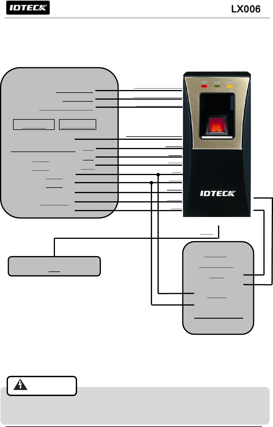
5. PRODUCT EXPLANATION
5.1 PANEL LAYOUT
(Figure: Panel Codes)
5.2 CONNECTION LAYOUT
(Figure: Connecter Arrangement)
CON-1
CON-2
CON-3
CON-4
Tamper SW
DIP SW
Status LED
Fingerprint
Scanner
Speaker
Proximity Reader
11
5.3 COLOR CODED & WIRING TABLE
I/O PORT NAME
SIGNAL NAME
WIRE COLOR
CON-1: Power (2PIN Connector)
Power (+12V)
DC +12V
Red
Ground
GND (-)
Black
CON-2: In/Output (6PIN Connector)
EX Input Wiegand DATA0
EX-DATA0
ABA Track II Data In
Pink
EX Input Wiegand DATA1
EX-DATA1
ABA Track II Clock In
Cyan
NC
Brown
NC
Blue
RS4
85
RS485-A(+)
RS485-A(+)
Yellow
RS485-B(-)
RS485-B(-)
Gray
CON-3: In/Output (8PIN Connector)
Wiegand DATA 0
DATA-0
ABA Track II Data Out
Green
Wiegand DATA 1
DATA-1
ABA Track II Clock Out
White
ERROR SIGNAL OUT
ERROR SIGNAL OUT
ABA Track II CLS Out
Orange
OK SIGNAL OUT
OK SIGNAL OUT
Orange with Black stripe
TAMPER OUT
TAMPER OUT
Purple
EX_LED_CONTROL
EX_LED_CONTROL
Blue with White stripe
EX_BUZZER_CONTROL
EX_BUZZER_CONTROL
White with Red stripe
EX_SYS_CHANGE_IN
EX_SYS_CHANGE_IN
Gray with Red stripe
CON-4: TCP/IP (8PIN Connector) RJ45 Cable Connection
12
6. INSTALLATION TIPS & CHECK POINTS
Please refer to information below to stably operate the LX006.
6.1 CHECK POINTS BEFORE INSTALLATION
6.1.1 CABLE SELECTION
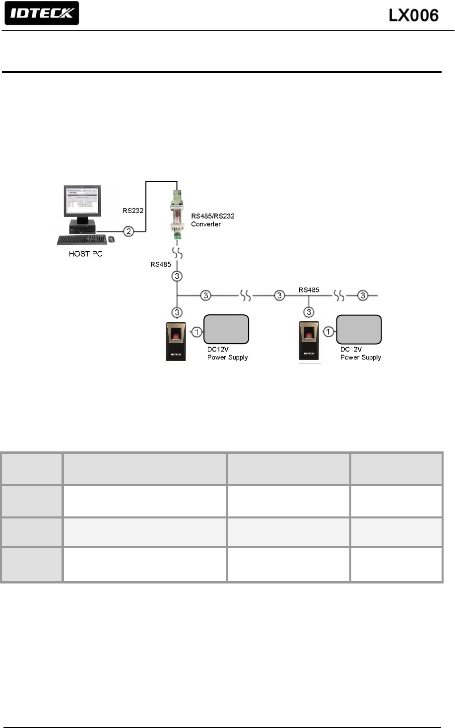
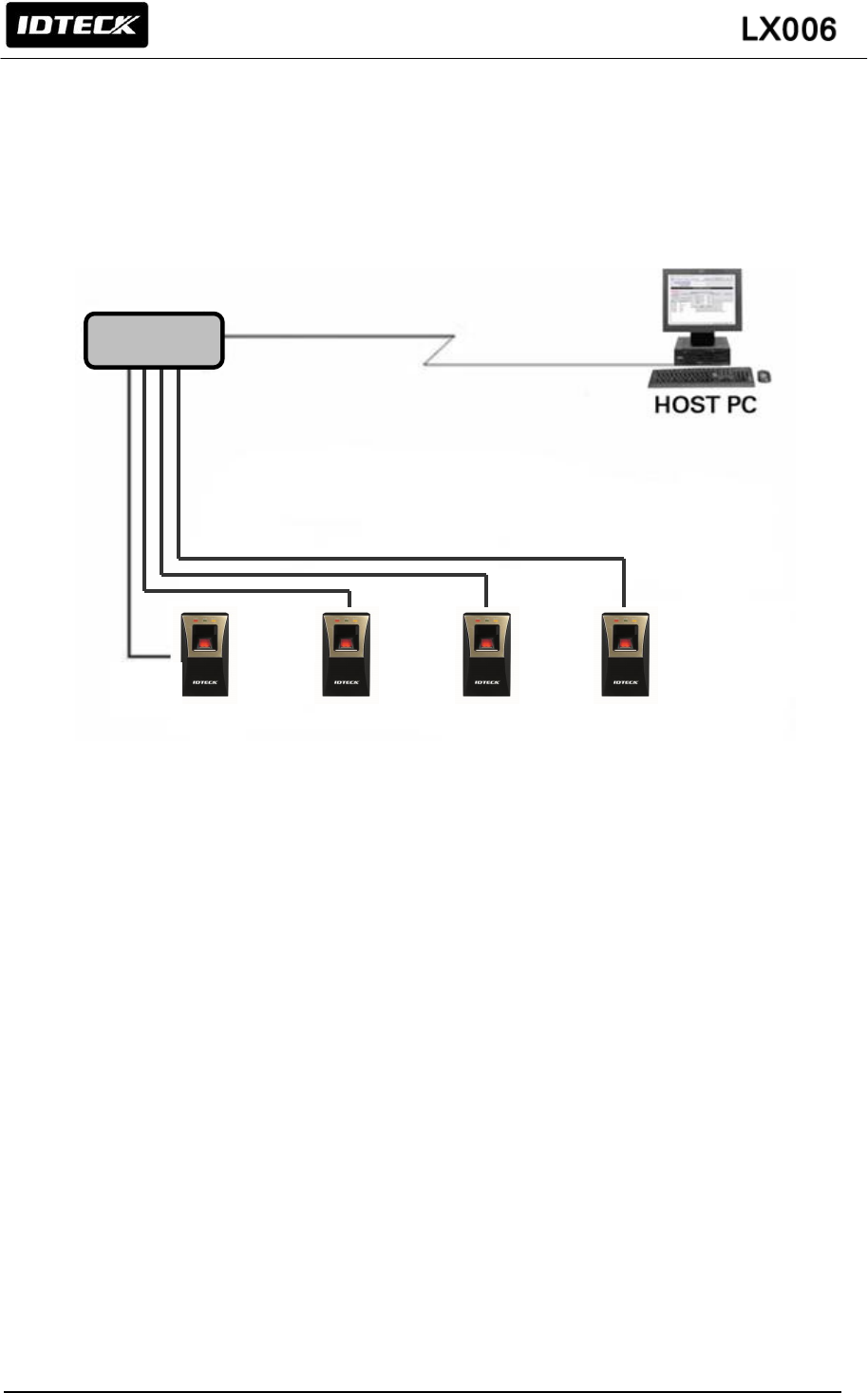
(Figure: System configuration)
6.1.2 RECOMMENDED CABLE TYPE AND PERMISSIBLE LENGTH OF CABLE
* Thicker wires are required if you connect the reader with high current consumption.
6.1.3 READER CONNECTION
If you install the reader in a long distance between the ACU and the reader, you should be aware
there could be voltage drop between ends of GND wire. For example, if you connect a reader with
100mA current consumption at 100m distance (assume to using DC resistance of cable of
100Ω/100m) and the reader power is supplied from the ACU, the voltage drop of the GND wire will
be 1V. In this case, the Wiegand data signal cannot be measured lower than 1V.
No
Description
Cable
specification
Maximum
distance
1
LX006 Power (DC+12V)
DC Power -> LX006
Belden #9409,18 AWG
2 conductor, unshielded
3m
*2
RS232 Cable converter->Host P.C.
Belden #9829, 24 AWG
2-twisted pair, shielded
15m
3
RS485 Cable
LX006 -> LX006
LX006 -> Converter
Belden #9829, 24 AWG
2-twisted pair, shielded
1,200m
POWER
POWER
13
The most of ACU is capturing the signal by the voltage level of data input. 1V is the critical point
whether the ACU read the data logic “1” or logic “0” therefore the reader output cannot be read
correctly from the ACU.
There will be two methods to reduce the voltage drop and ACU can read data correctly.
Reduce the DC resistance of GND wire;
Using thick cable or add more wires to GND wire in parallel. If you connect 4 wires in parallel for
GND, the DC resistance of GND wire will be reduced to 1/4 of single wire.
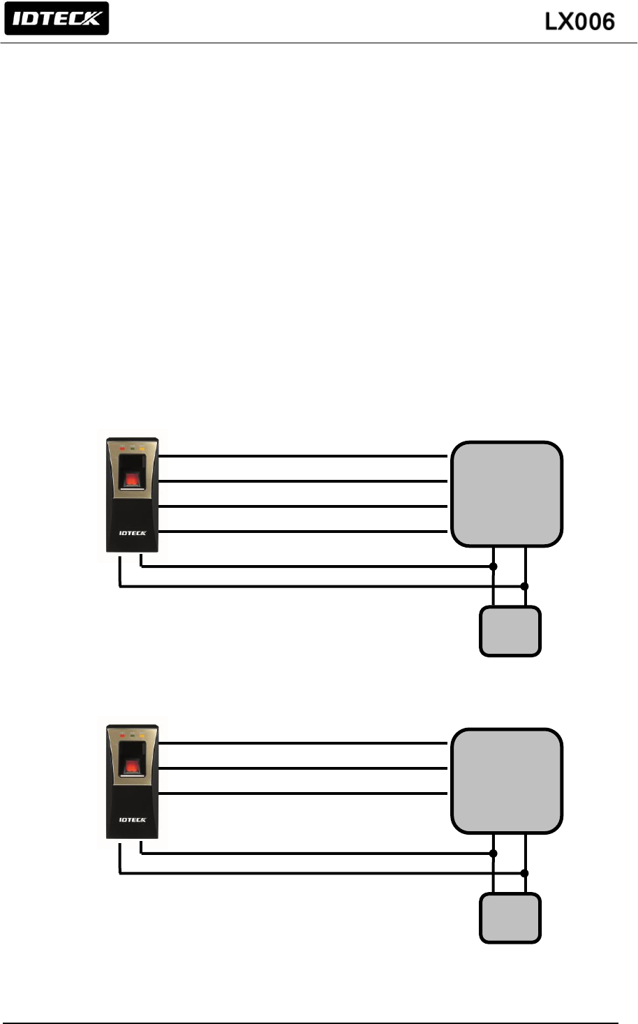
Use separate power for the reader;
Disconnect +12V wire from the ACU and connect external power supply to the reader nearby. There
will be no current flow through the GND wire and no voltage drop between ends of GND wire.
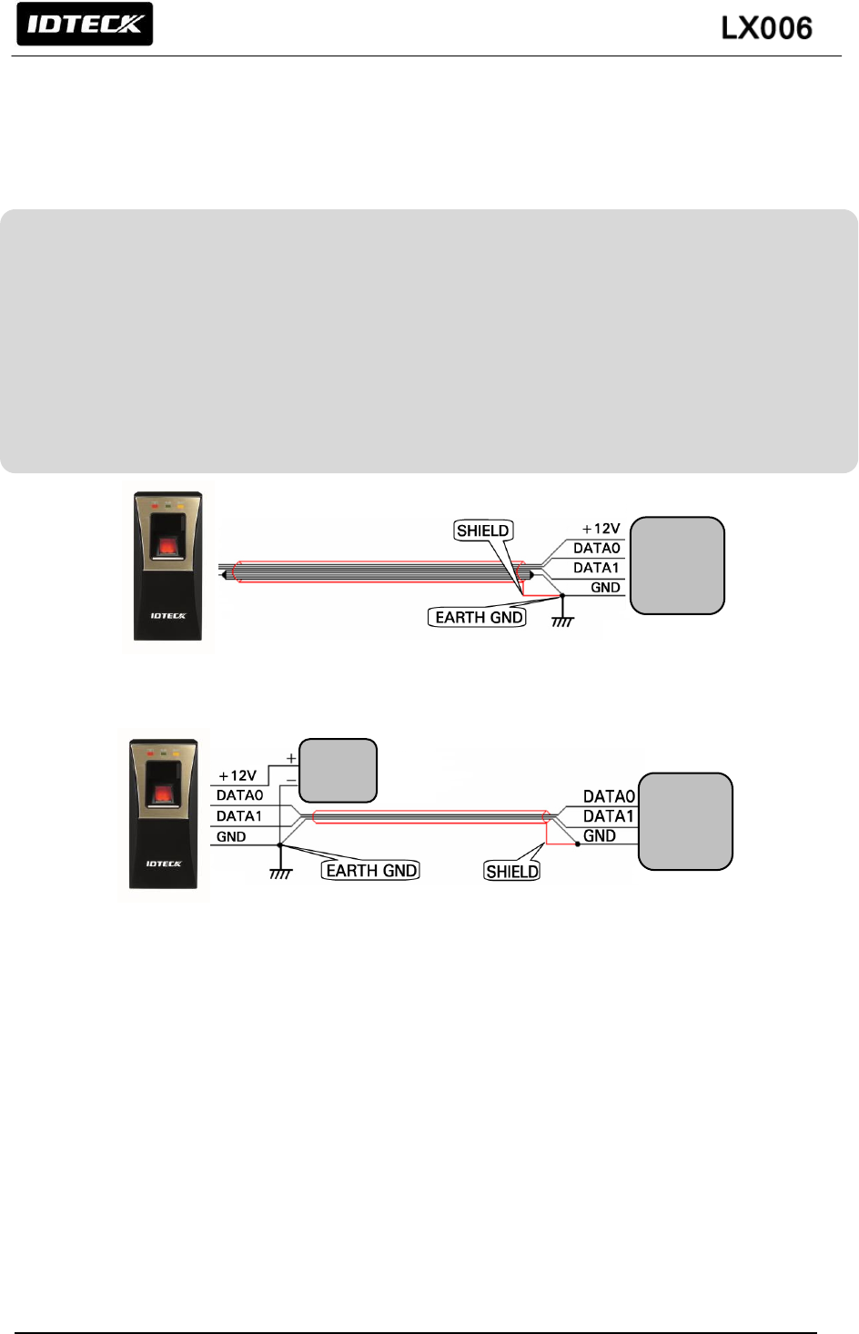
(Figure: When Sharing a Single Power Supply for Multiple Units)
(Figure: When Using a Separate Power Supply for the LX006)
6.2 CHECK POINTS DURING INSTALLATION
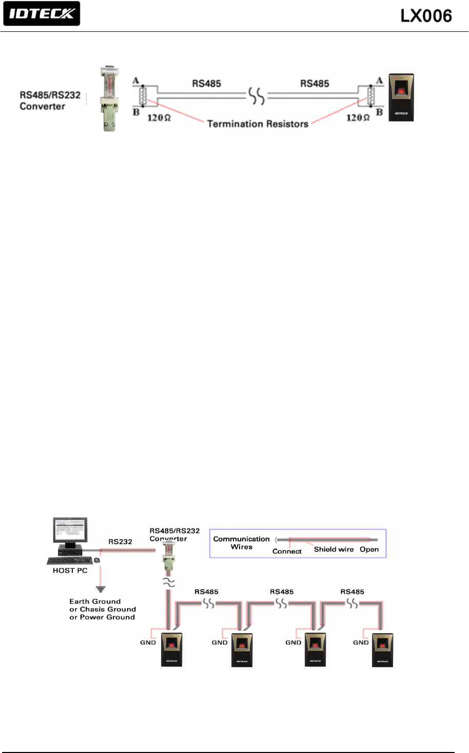
6.2.1 TERMINATION RESISTOR
Termination resistors are used to match impedance of the network to the impedance of the
transmission line being used. When impedance is mismatched, the transmitted signal is not completely
absorbed by the receiver and a portion of signal is reflected back into the transmission line.
The decision whether or not to use termination resistors should be based on the cable length and data
rate used by the communication system.
ACU
POWER
ACU
14
6.2.2 HOW TO CONNECT TERMINATION RESISTORS
(Figure: Termination resistors for 2 wire RS485 communication system)
6.2.3 GROUNDING SYSTEM FOR COMMUNICATION CABLE
We recommend proper grounding system on the communication cable. The best method for grounding
system is to put the shield wire of the communication cable to the 1st class earth grounding; however it
is not so easy to bring the earth ground to the communication cable and also the installation cost is
raised. There will be three grounding point where you can find during installation;
1, Earth Ground 2. Chassis Ground 3. Power Ground
The most important point for grounding system is not to connect both ends of shield wires to the
grounding system; in this case there will be a current flow through the shield wire when the voltage
level of both ends of shield wire is not equal and this current flow will create noise and interfere to
communications. For the good grounding, we recommend you to connect ONLY one end of shield wire
of communication cable to grounding system; If you find earth ground nearby, connect one end of
shield wire to earth ground; If you do not have earth ground nearby, find chassis ground and connect
one end of shield wire to chassis ground; If you do not find both earth ground and chassis ground, then
connect one end of shield wire to power ground. (GND of LX006).
Note that if the chassis ground is not properly connected to the earth and floated from the ground level,
then grounding to the chassis ground will make the worst communication; in this case we recommend
you to use power ground instead of chassis ground.
(Figure: Grounding system)
15
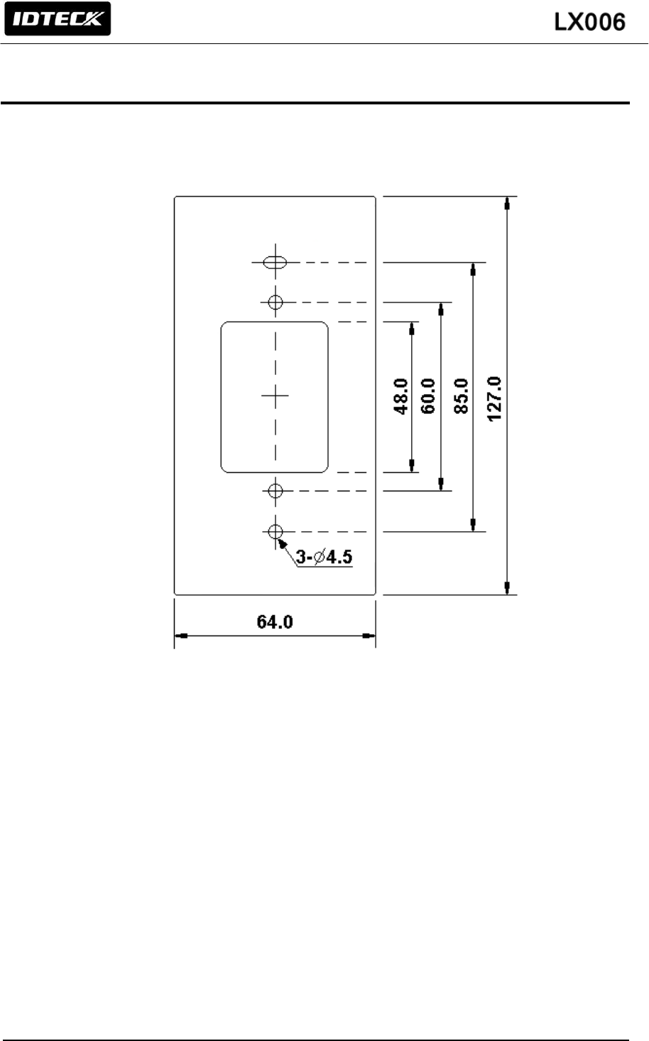
7. INSTALLATION OF THE PRODUCT
7.1 WALL MOUNT DRAWING
(Unit: mm)
(Figure: Wall Mount)
7.2 INSTALLATION OF WALL MOUNT
- Place the Wall Mount on the desired position on the wall and mark the locations of the 2 screw holes.
- Drill a hole in the center of the Wall Mount for cable.
- Take out the cable from the center of hole.
- Wire cable to four connecters and then perform initialization and set communication ID.
- By using of one screw on the bottom, fix the Wall Mount with LX006.
16
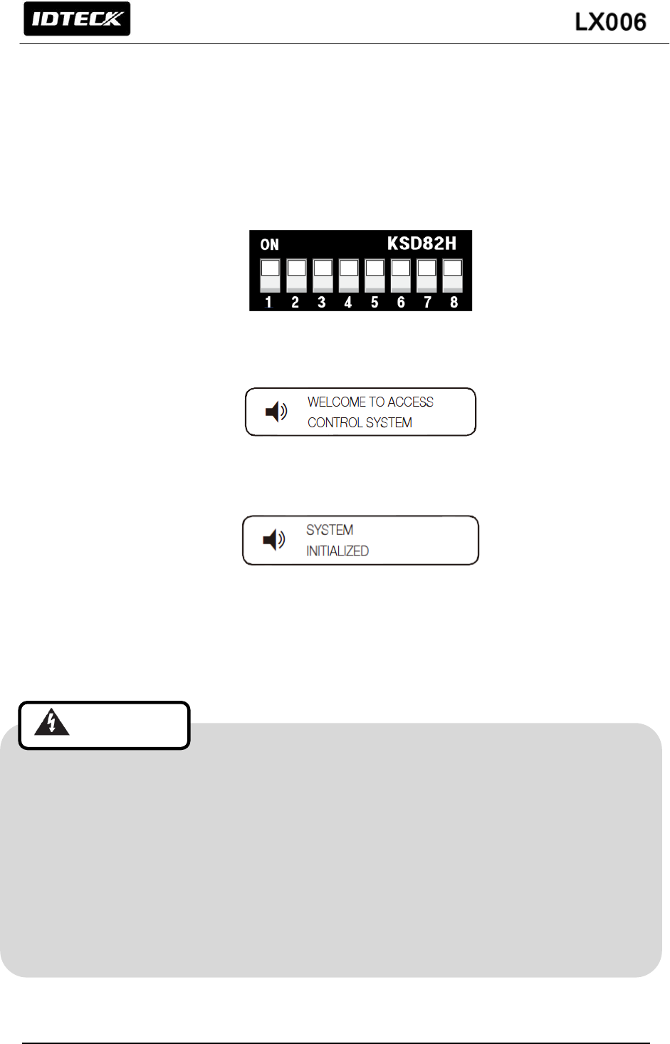
7.3 SYSTEM INITIALIZATION
Initialize the system using the DIP switch on the rear of the product.
1. Disconnect the power supply.
2. Position the DIP switch on the rear of the product to ON (upside) and apply power to the
product.
3. The product sounds a beep once with a voice message, and proceed with the hardware
initialization process.
4. When the initialization is done, the product sounds a beep three times with a completion
message output.
The product keeps sounding the beep until you change the communication address.
5. Use the DIP switch to specify the BOARD ID.
Refer to “7.4 COMMUNICATION ID SETTING”.
6. You must specify the communication address and register the master ID.
• After fixing the LX006 on the wall mount, you can’t initialize the system by this procedure.
But you can initialize it through Application Software
• If you initialize the system using software, all data except for the IP setting returns to the
default.
• If you initialize the hardware system, all data settings return to the factory default. (including
IDs, fingerprint data, master ID, card number output format, IP)
• If the communication address is set to 255, the initialization process gets started
immediately
Cautions
17
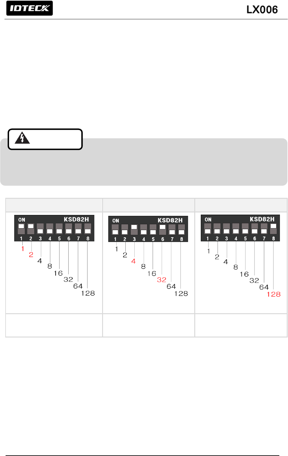
7.4 COMMUNICATION ID SETTING
LX006 can upload/ download user’s information by application software and adjust setting values.
Communication ID is the unique communication address to recognize each LX006 in the software so
each communication ID on the same communication loop must not be duplicated.
There is 8-bit DIP switch on the back of LX006 for communication ID setting and each channel of
DIP switch has assigned address values. The communication ID is calculated by the sum value of
each bit set to “ON” position. Communication ID can be set from ‘0’ to ‘255’. Refer to examples below
to set communication ID.
Each communication ID in the same communication loop must not be duplicated. If the same
communication IDs are on the loop, it may cause communication error.
Example 1
Example 2
Example 3
1+2 = 3
(Communication ID = 3)
4+32 = 36
(Communication ID = 36)
128= 128
(Communication ID = 128)
(Figure: Communication ID Setting Example)
Cautions
18
7.5 WIRING
7.5.1 WIRING LAYOUT
7.5.2 Power Wiring
1. Connect +12V (+) wire of Power to Red wire of LX006
2. Connect GND (-) wire of Power to Black wire of LX006
You can use separate power supplies for the LX006 and the Controller; however, the GND(-)
wire must be connected to the Black wire, in any case.
Cyan
Pink
8bit Burst
26bit/34bit(SR)
Wiegand
DATA1
DATA0
DC +12V
GND(-)
External reader
HUB
Red
Black
Yellow
Gray
Purple
Green
White
Orange
Orange with Black stripe
White with Red stripe
Gray with Red stripe
Blue with White stripe
RJ45
ABA Track II
Wiegand
System Mode Control
LED Control
Buzzer Control
Authentication input
CLS
DATA1
DATA0
DC12V
GND(-)
CLK
DATA
TAMPER
Controller
RS485-A(+)
RS485-B(-)
Authentication error input
Cautions
19
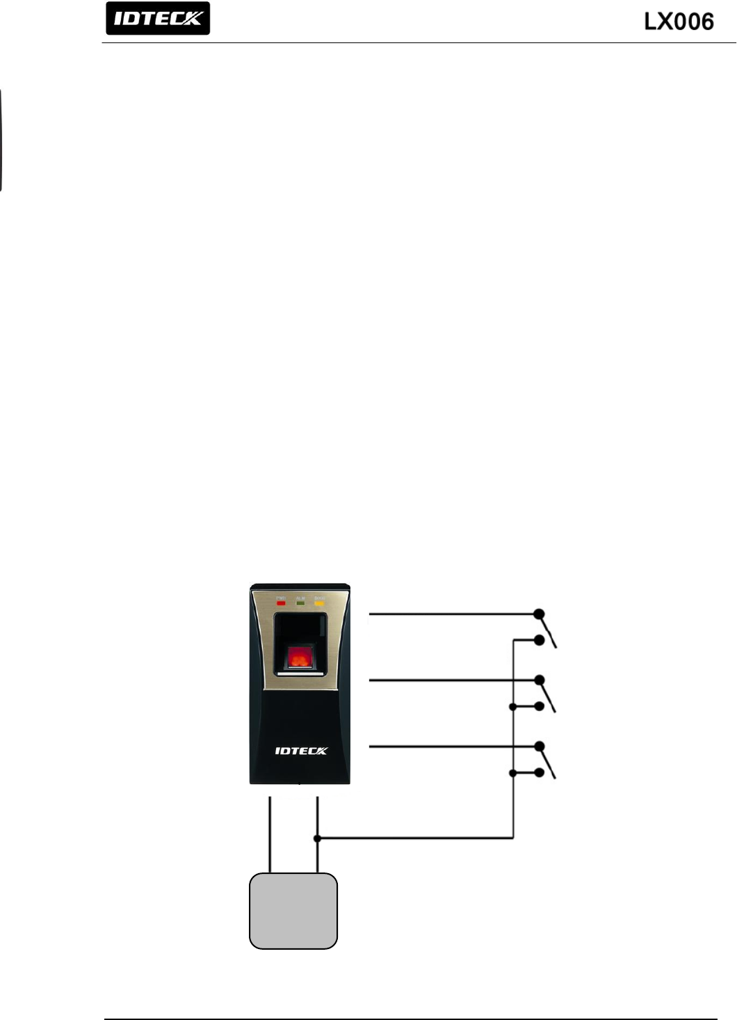
7.5.3 INPUT WIRING
External LED Control Connection
Connect the LED Control Input wire (Blue wire with White stripe) to the NO port of controller relay
output, and GND to the COM port. Set I/O of the controller; then you can control tuning on and off the
green LED. While the LED control is working, the green LED stays on.
The controller can use the I/O setting to set the LED controller so that it displays the additional LED
status for authorized/unauthorized access. For more information about the I/O setting of the controller,
refer to the controller’s user manual.
External Buzzer Control Connection
Connect the Buzzer Control Input wire (White wire with Red stripe) to the NO port of controller relay
output, and GND to the COM port. Set I/O of the controller; then you can generate beep sound. While
the buzzer control is working, the product keeps sounding beep.
The controller can use the I/O setting to set the buzzer controller so that it sounds the additional beep
for authorized/unauthorized access. For more information about the I/O setting of the controller, refer
to the controller’s user manual.
External Input Device Connection (System Operating Mode Change through External Input)
Connect the System Mode Control wire (Gray wire with Red stripe) to the NO port of controller relay
output, and GND to the COM port. Set I/O of the controller; then you can control the system mode.
While the system mode is controlled, RF Only mode is operated.
With I/O or time schedule setting, the controller can switch system operation mode in a specific time
section. For more information about the I/O setting of the controller, refer to the controller’s user
manual.
(Figure: Input Connection)
POWER
12V
GND
Buzzer Control
White with Red stripe
LED Control
Blue with White stripe
System Mode Control
Gray with Red stripe
20
7.5.4 OUTPUT CONNECTION
Wiegand DATA Output Connection
1. Connect Wiegand Data 0 wire (Green wire) to Wiegand Data 0 terminal of the Controller.
(Used for DATA when ABA Track II is output)
2. Connect Wiegand Data 1 wire (White wire) to Wiegand Data 1 terminal of the Controller.
(Used for CLOCK when ABA Track II is output)
3. The GND(-) wire must be connected between the LX006 and the Controller.
Access Error Signal Connection
- Connect the Access Error Signal wire (Orange wire) to the Access Error Input terminal of the
Controller. (Used for CLS when ABA Track II is output)
Access OK Signal Connection
- Connect the Access OK Signal wire (Orange wire with Black stripe) to the Access OK Input
terminal of the Controller. (Not used when ABA Track II is output)
(Figure: Wiegand Output Connection)
(Figure: ABA Track II Output Connection)
ACU
OK Signal Out (Orange with Black stripe)
Error Signal Out(Orange)
)
DATA1(White)
)
DATA0(Green)
POWER
12V
GND
ACU
CLS (Orange)
CLOCK(White)
)
DATA(Green)
)
POWER
12V
GND(-)
21
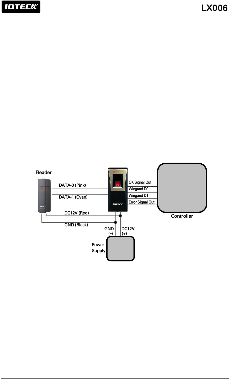
7.5.5 EXTERNAL READER CONNECTION
Proximity Reader Connection
1. Connect the DC+12V wire of Power Supply to (+) wire of reader.
2. Connect the GND(-) of Power Supply to (-) wire of reader
3. Connect the Wiegand Data 0 wire of the External Reader to the Wiegand Input Data 0 wire
of LX006 (Pink wire).
4. Connect the Wiegand Data 1 wire of the External Reader to the Wiegand Input Data 1 wire
of LX006 (Cyan wire).
5. The GND(-) wire must be connected between the external and the LX006.
Compatible Reader:
LX006:
Standard 26bit Wiegand proximity reader
Standard 26bit Wiegand + 4/8bit burst proximity/ keypad reader
LX006SR:
Standard 34bit Wiegand proximity reader
Standard 26bit Wiegand + 4/8bit burst proximity/ keypad reader
(Figure: External Reader Connection)
POWER
ACU
22
8. COMMUNICATION
8.1 RS485 COMMUNICATION PORT CONNECTION
8.1.1 RS485 COMMUNICATION PORT CONNECTION (SINGLE CONNECTION)
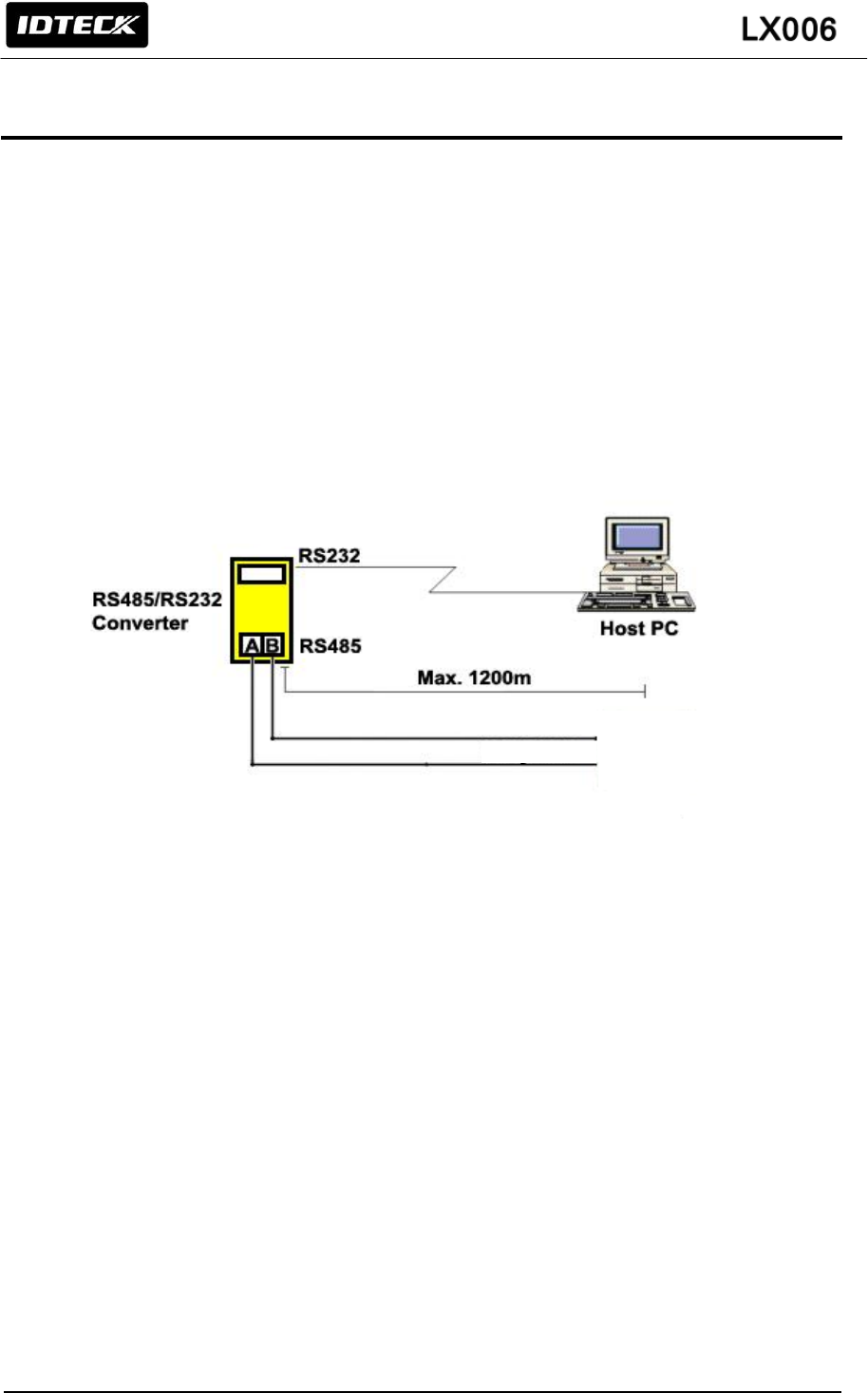
An RS-485/RS-232 converter is required to connect serial communication RS485 between the LX006
Main Unit and the Host Computer.
- Connect RS485 - RTX (+) (Yellow) wire of Main Unit to RS485-A of Converter.
- Connect RS485 - RTX (-) (Gray) wire of Main Unit to RS485-B of Converter.
- Plug the RS232 9-pin connector of INC300 converter into COM1 or COM2 Port of Computer.
- Install and run the application software.
(Figure: RS485 Connection between LX006 and Host PC)
* The maximum of cable length can be shortened depending on communication speed, the type of
communication cable and cable installing environment.
Gray Wire
Yellow Wire
23
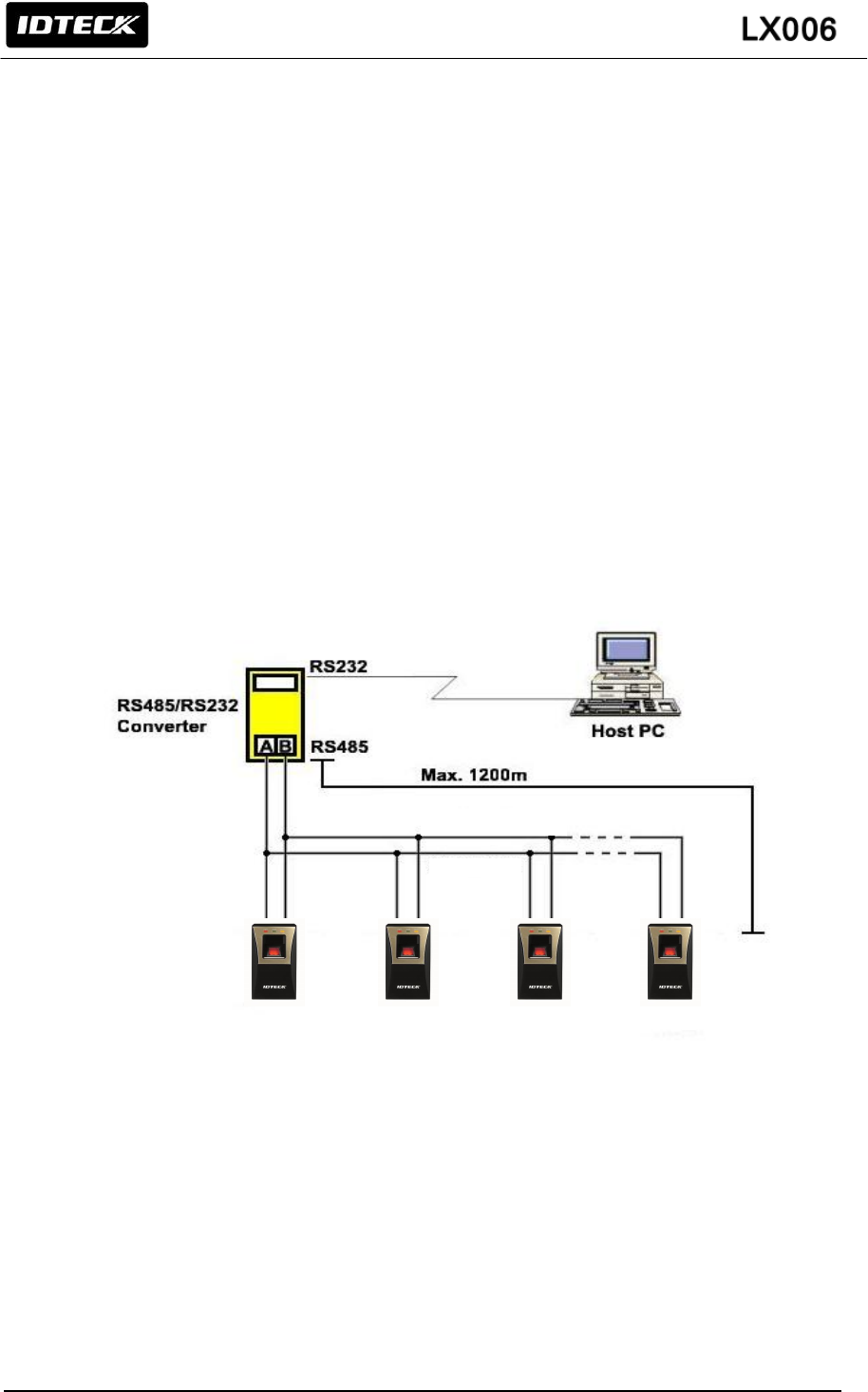
8.1.2 RS485 COMMUNICATION PORT CONNECTION (MULTIPLE CONNECTION)
RS485/RS232 converter is required to use RS485 communication between multiple LX006s and a host
computer. Please follow the following instructions.
First, you have to connect all RS485 port of all LX006s in parallel. (Maximum of 255)
- Connect RS485-A(+) (Yellow) of one LX006 to RS485–A(+) (Yellow) of another LX006.
- Connect RS485-B(-) (Gray) of one LX006 to RS485–B(-) (Gray) of another LX006.
- Set different COMM ID for each LX006.
Second, you have to connect one of RS485 port of LX006 to RS485/RS232 converter.
- Connect RS485-A(+) (Yellow) of one LX006 to RS485-A port of the Converter.
- Connect RS485-B(-) (Gray) of one LX006 to RS485-B port of the Converter.
- Plug in the RS485/RS232 9-pin connector of the converter to the COM1 or COM2 Port of the
PC.
- Install and run LX006 Application Software.
(Figure: Multiple Connection of LX006 with RS485)
Gray Wire
Yellow Wire
24
8.2 TCP/IP COMMUNICATION PORT CONNECTION
For TCP/IP communication, external cable is required to connect to CON4 (8PIN connecter).
Please follow the following instructions.
1. Connect the LAN cable of the network system to the RJ45 jack of the LX006.
2. Install and run the Application Software.
(Figure: TCP/IP Communication connection of LX006)
RJ45
RJ45
RJ45
RJ45
HUB

25
9. BASIC SETTING
9.1 INITIALIZATION OF LX006
- Initialization should be performed before mounting the LX006 to the Wall Mount.
- If you need to initialize LX006 after installing it on the wall, you can use the Application Software to
do that. (Refer to the Software Manual for more information.)
- For more information about how to initialize the LX006, refer to ‘7.3 SYSTEM INITIALIZATION’.
9.2 COMMUNICATION ID SETTING
- The LX006 can upload or download user’s fingerprint data using the Application Software. You can
also customize the settings of LX006 for your needs.
- There is one 8 channel DIP switch on the back of FGR006/SR unit for communication ID setting.
Each channel of DIP switch has assigned address value. The communication ID is calculated by the
sum value of each switch set to “ON” position. Communication ID can be set from ‘000’ to ‘255’.
Please refer to the ‘7.4 COMMUNICATION ID SETTING’ for more details.
If the Controller is initialized, all data stored in the Controller will be cleared and the default
setting values (factory setting values) will be reloaded. Therefore, the Initialization should be
performed by authorized person only. It is strongly recommended to upload all events data
before initialization.
Cautions

26
10. OPERATION MODE
10.1 MASTER CARD REGISTRATION MODE
While the LX006 is operating in the Master Card Registration Mode, the Red and Green LEDs are lit.
10.1.1 MASTER CARD REGISTRATION
The card presented to the LX006 for the first time after initialization becomes the master card.
※ NOTE: Fingerprint verification is not used for the Master Card.
After the Master Card is recognized, the Green LED blinks with 3 beeps.
10.1.2 MASTER CARD CHANGE
You can change the registered Master Card after system initialization.
※ CAUTION : If you initialize the system, all user data will be deleted.
Alternatively, you can change the Master Card using the application software. (Using the application
software keeps the user data unchanged.)
10.1.3 MASTER CARD FUNCTION.
The Master Card is used to toggle the LX006 between the Reader Mode and the Registration Mode.
※ For example,
If you present the master card in the Reader Mode, the LX006 shifts to the Registration Mode.
If you present the master card in the Registration Mode, the LX006 shifts to the Reader Mode.
10.2 REGISTRATION / DELETION MODE
While the LX006 is operating in the Registration/Deletion Mode, the Yellow and Green LED blink.
10.2.1 REGISTRATION MODE FUNCTION
In the Registration Mode, you can register new user cards or delete registered user cards.
- If you present a registered user card, it will be removed from the LX006. (4 beeps)
- If you present an unregistered user card, it will be newly registered to the LX006. (3 beeps)
- If fingerprint registration is failed, only card ID is registered then it works as RF Only mode.
10.2.2 USER CARD REGISTRATION
1. Present the Master Card to the LX006.

27
2. Yellow and Green LED indicators blink.
3. Present the Proximity Card you want to delete to the LX006.
4-1. RF + FINGER MODE:
After presenting the user card you want to register, you should enter the desired fingerprint twice.
Follow the steps below to register a new user card;
- Present the proximity card to the LX006.
- Place the fingerprint on the fingerprint scanner while red light is illuminated from it
- Lift the fingerprint up when the red light from the scanner turns off.
- Place the fingerprint on the fingerprint scanner once again while the red light is illuminated again.
- 3 beeps will be generated if the registration is successfully completed. If the fingerprint registration
is not successful, only Card ID is registered then beep sound is generated 3 times.
- If you want to register more user cards, repeat the steps above.
- If you want to finish registration process, present the Master Card to return to the Reader Mode.
4-2. RF Only:
If you’d like to register a new user card without use of fingerprint, don’t place the fingerprint on the
fingerprint scanner and wait until the red light from the scanner turns off automatically.
-Just present the user card you want like to register.
-After the registration is successfully completed, you’ll hear 3 beeps. If the registration is not
successful, you’ll hear only 2 beeps.
-If you’ want to register more user cards, repeat the procedure above. Or, if you’d like to finish
registration process, present the Master Card to return to the Reader Mode
(Figure: Correct placement of fingerprint)

28
10.2.3 USER CARD DELETION
To delete registered user cards, follow steps below;
1. Present the Master Card to the LX006.
2. Yellow and Green LED indicators blink.
3. Present the Proximity Card you want to delete to the LX006.
4. After the deletion is successfully completed, you’ll hear 4 beeps. If the deletion is not successful,
you’ll hear 2 beeps.
5. If you want to delete more user cards, repeat the steps above.
6. To finish the user card deletion process, present the Master Card to return to the Reader Mode.
10.3 READER MODE
While the LX006 is operating in the Reader Mode, the Red LED is lit.
10.3.1 READER MODE FUNCTION.
In the Reader Mode, the LX006 authorizes or denies users who attempt access by presenting their
cards.
- If a user is authorized, the LX006 transmits the User ID to the controller.
- If a user fails to be authorized, the LX006 transmits the error signal to the controller. (The error
signal is not generated when using ABA Track II format.)
10.3.2 AUTHORIZATION
If the LX006 is operating in the RF-Only Mode or the User Card is registered as an RF-Only mode
card,
1. Present the registered card to the LX006.
2. If the card is authenticated, a long beep will be generated and the Green LED will be lit.
If the card fails to be authenticated, the LX006 output the user ID information according to the
output format setting.
If the LX006 is operating in the RF+FINGER Mode and the User Card is registered as an
RF+FINGER mode card,
1. Present the registered card to the LX006.
2. After the card is recognized, the fingerprint scanner emits red light.
3. Place the registered fingerprint on the scanner.
4. If the fingerprint is successfully verified, a long beep will be generated and the Green LED will be lit.
The User ID will be transmitted according to the output format setting.
5. If the fingerprint fails to be verified, the buzzer will generate 2 short beeps and the Yellow LED will
blink twice. Also, an Access Error Signal output (Low Active) will be generated for 500ms. (The
29
error signal is not generated when using ABA Track II format.)
If the card hasn’t yet been registered,
1. The buzzer generates 2 short beeps and the Yellow LED blinks twice to indicate that the presented
card is unregistered or deleted.
2. When an unregistered card is presented or a fingerprint is not verified, an Access Error Signal
output (Low Active) will be generated for 500ms. (The error signal is not generated when using
ABA Track II format.)
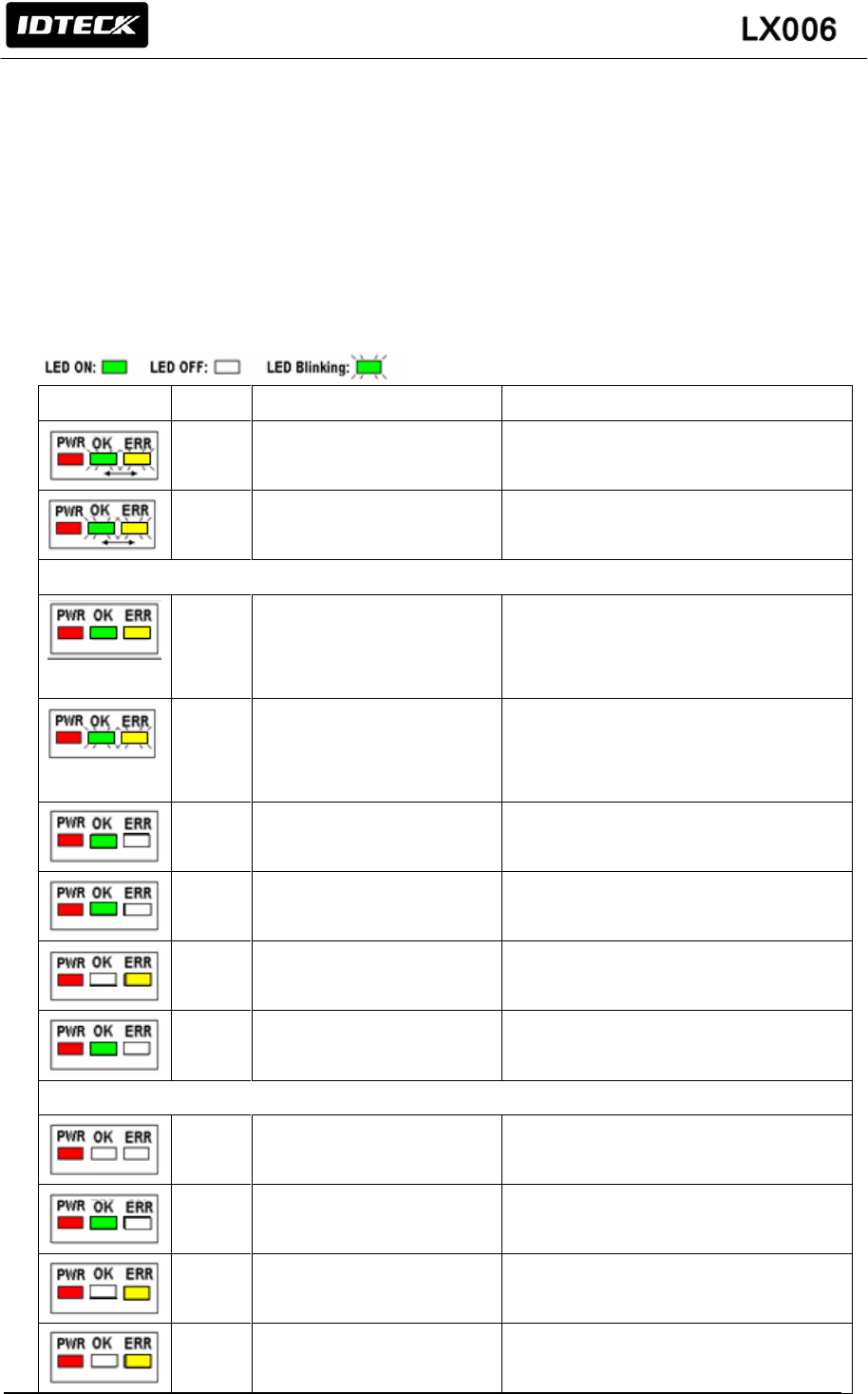
10.4 READER INDICATOR
LED
BEEP
VOICE MESSAGE
STATUS
1
WELCOME TO ACESS
CONTROL SYSTEM
Power is applied and the LX006 is booting up.
X
SYSTEM INITIALIZED
The initialization has been finished.
REGISTRATION MODE
X
MASTER ID REGISTRATION
MODE
In the status of system initialize. The card
recognized in this status, it becomes Master
card.
X
REGISTRATION AND
DELETION MODE,
PRESENT A CARD
User card registration/deletion is available
3
BEEPS
ID REGISTERED
User card registration successfully completed
3
BEEPS
FINGERPRINT REGISTERED
User card/Fingerprint registration successfully
completed
2
BEEPS
FINGERPRINT REGISTRATION
FAILED, PLEASE TRY AGAIN
User card/Fingerprint registration is failed
4
BEEPS
ID DELETED
User card/Fingerprint deletion successfully
completed
READER MODE
X
READER MODE
The LX006 is in its normal status, waiting for a
User Card to be presented.
1 BEEP
ACCESS GRANTED
Authentication completed
2
BEEPS
ACCESS DENIED,
PLEASE TRY AGAIN
Authentication failed
4
BEEPS
ID UNREGISTERED
Unregistered person

30
10.5 DEFAULT SETTINGS
The initialization before installation restores the default values (factory settings) of the LX006. For
desired applications, you may adjust or customize the settings via the Application Software.
The default values for the basic settings are as follows;
1. Operating Mode: RF + FINGER
2. Fingerprint Registration: 1 ID 1 Finger Two Template
3. Output Format: 26bit Wiegand/34bit Wiegand(SR)
4. Input Format: 26bit Wiegand/34bit Wiegand(SR)
5. Output Mode: Normal Mode
6. Adaptive Mode: Disabled
7. High Security Mode: Enabled
8. Voice Volume: 3
31
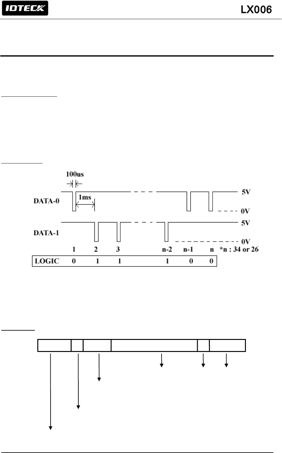
11. OUTPUT FORMAT
11.1 WIEGAND OUTPUT (DEFAULT)
Data format (26-bit)
Bit 1 / Bit 1: From Bit 2 to Bit 13 / From even parity Bit 2 to Bit 17
Bit 2 to Bit25 / Bit 2 to Bit33: 3-byte ID number / 4-byte ID number
Bit 26 / Bit 34: From Bit 14 to Bit 25 / From odd parity Bit18 to Bit 33
Output Timing
11.2 ABA TRACK Ⅱ (SELECTABLE USING THE SOFTWARE)
Data format
Start Character
(11010 Hex ‘B’)
Facility Code
(00000~00255)-LX006
(00000~65535)-LX006SR
Low bit first, odd parity last
ID number
(00000~65535)
LRC
Zero bit
Zero bit (10bit)
32
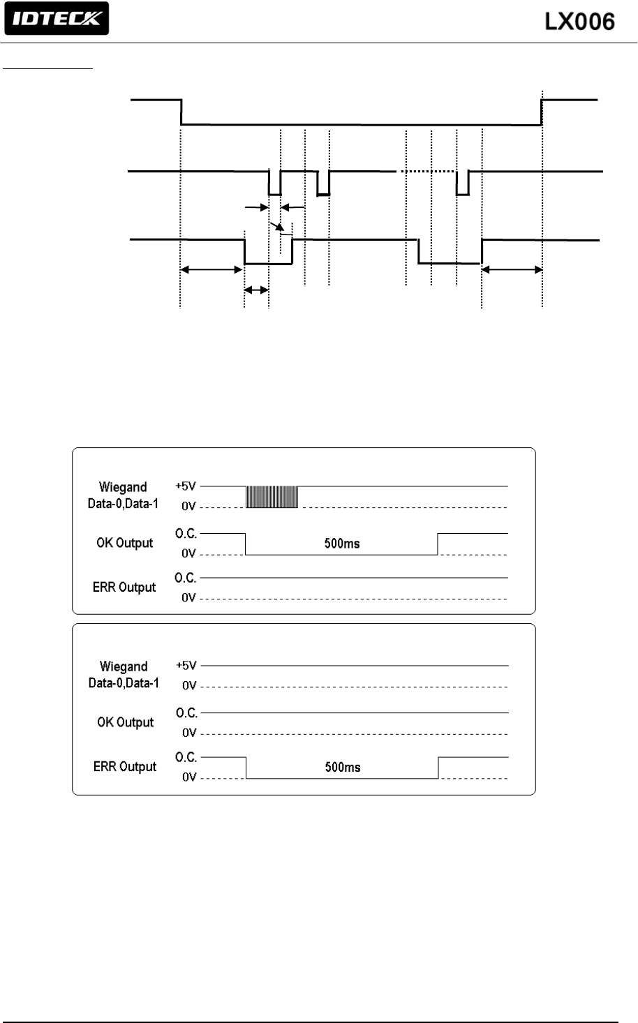
Output timing
11.3 OUTPUT MODE
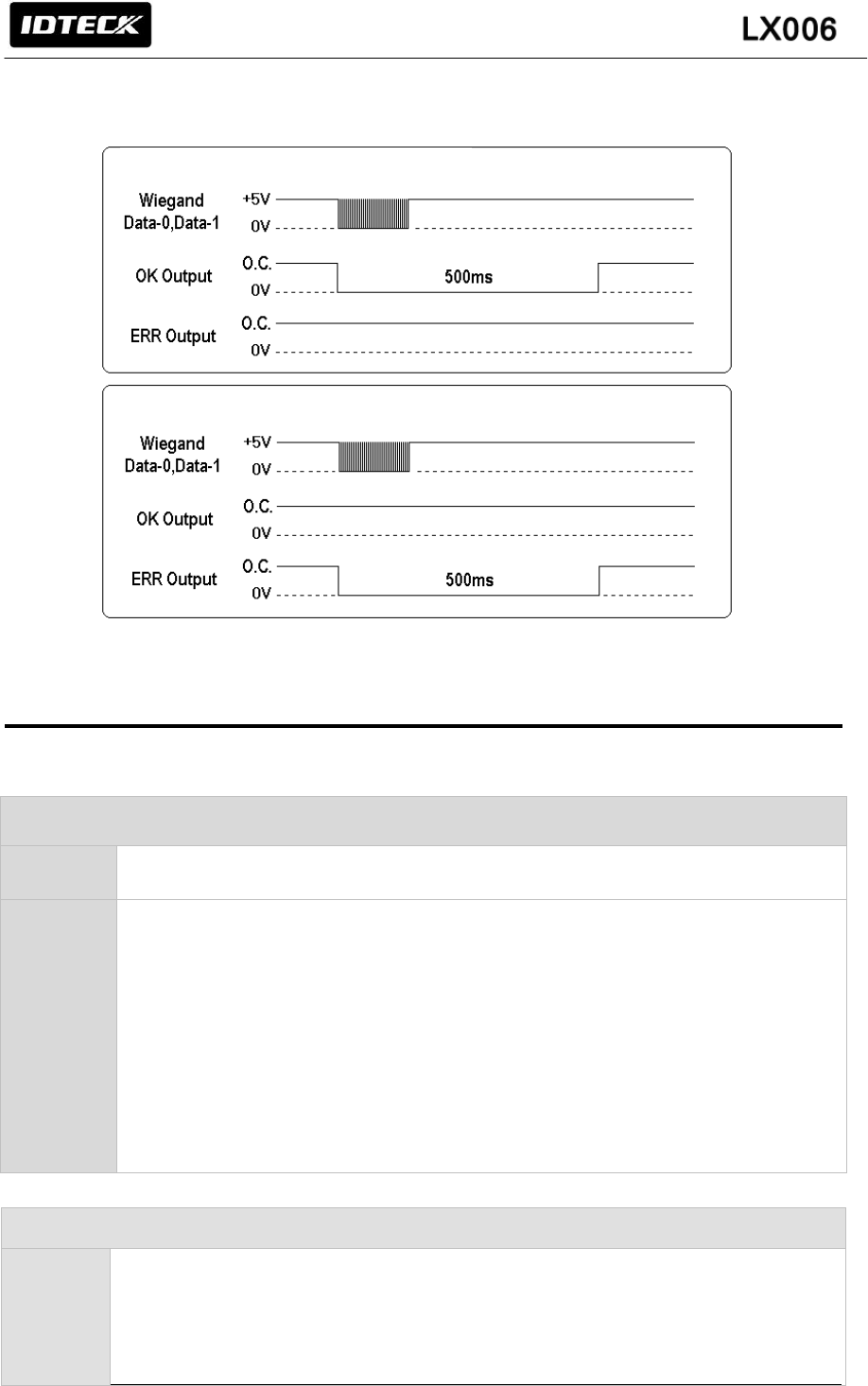
11.3.1 NORMAL OUTPUT MODE
1240us
940us
6000us
6000us
1544us
CP
CLK
(RD1)
Data
(RD0)
User ID / Fingerprint authorized
User ID unregistered/ Fingerprint error
33
11.3.2 EXTENSION OUTPUT MODE (SET BY APPLICATION SOFTWARE)
12. APPENDIX
A. Trouble Shooting
☞ Unable to enter the registration mode with master card
Cause
Of master card registration error or of setup error
Cause
1. Check a master card.
Try changing a master card and enter the registration mode with changed card.
2. Initialize the unit referring to user’s manual. (When this problem occurs before
mounting the LX006 on the wall)
* You can use application software for initialization if the LX006 is already
mounted on the wall.
3. If the problem still remains after following the procedure above, contact the
designated service center.
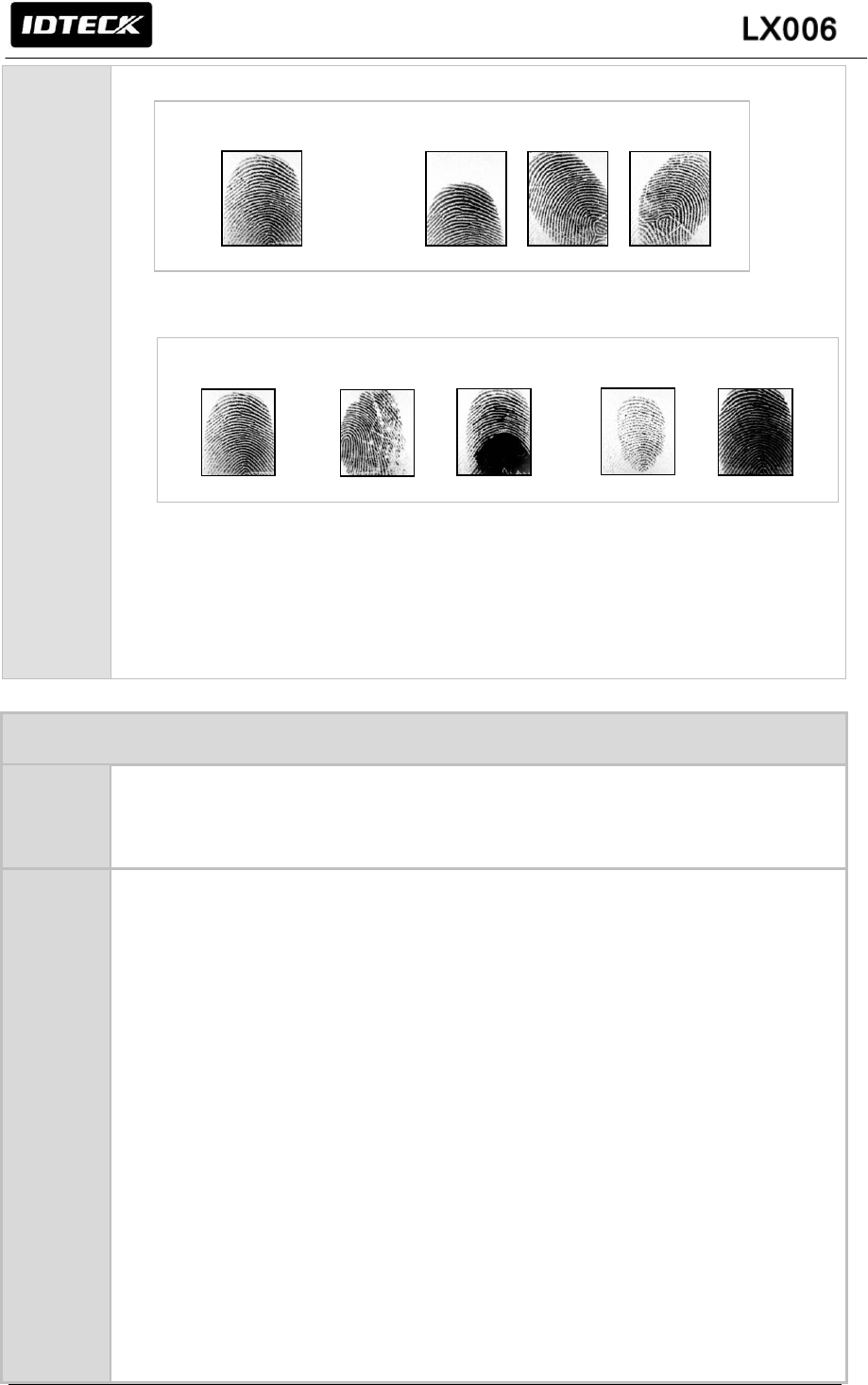
☞ Fingerprint isn’t registered or authenticated.
Cause
1. Check the fingerprint position on the scanner.
2. Check condition of the fingerprint.
3. Check whether ADAPTIVE MODE is applied or not. If not, Set the mode as
ADATIVE MODE
User ID / Fingerprint authorized
User ID unregistered/ Fingerprint error
34
정상적인 지문 위치가 잘못된 지문들
Cause
1. Check the fingerprint position on the scanner. .
2. Check condition of the fingerprint.
3. ADAPTIVE MODE is to compensate too dry and wet fingerprint. When ADAPTIVE
MODE is applied, the fingerprint capture time takes longer but the performance of
fingerprint recognition will be higher.
You can apply ADAPTIVE MODE using application software.
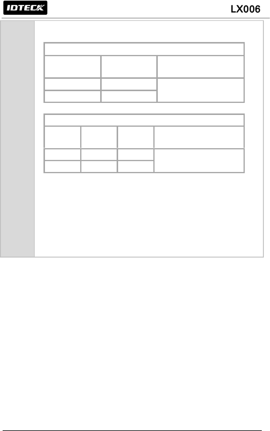
☞ The controller does not communicate with Host PC.
Cause
Defective cable is used, errors in wiring, an error in setting Communication ID of the
controller, or damage on the communication port (either on PC side or on the controller
side).
Solution
1. Please, check the settings of the application software and the controller.
- Check the controller’s Communication ID is linked with application software.
- Set the different Communication ID when two or more controllers are installed.
In case of using Serial communication.
- Check the communication speed (default 57600bps) is the same as the setting
on the application software. Please refer to application software manual.
- Make sure that the PC’s COM port is set correctly on the application software.
- The parameters at the application software should be set as follows.
Parity bit : NONE
Data bit : 8bit
Stop bit : 1bit
In case of using TCP/IP Communication
- Check IP, Subnet Mask, Gateway and Port setting value.
- Check more information about above setting value using the software manual.
Correct position
Wrong position
Normal
Dry Wet
Low pressure High pressure
35
2. Check the line connection for communication.
In case of RS485
RS485 (mono)
LX006
RS485/232
Converter
PC
RS485-A(+)
RS485-A(+)
RS232 Cable of connecter
RS485-B(-)
RS485-B(-)
RS485(Multi Drop)
LX006
LX006
RS485/232
Converter
PC
RS485-A(+)
RS485-A(+)
RS485-A(+)
RS232 Cable of connecter
RS485-B(-)
RS485-B(-)
RS485-B(-)
- When a multi-drop communication doesn’t work, test one-by-one
Communication from first.
In case of TCP/IP Communication
- Check the LED is flickering on the back of the product.
- If it is flickered, check the cable connection.
3. If the trouble remains after the procedure above, contact a designated service
center.
36
B. How to register fingerprint
Wet Fingerprint
Dry Fingerprint
Scarred Fingerprint
Injured Fingerprint
If Fingerprint is excellently recognized...
In case of dry fingerprint, please somewhat strongly press your finger (fingerprint) on
fingerprint recognition scanner.
In case of wet fingerprint, please lightly press your finger (fingerprint) on fingerprint
recognition scanner.
Please be always clean on the surface of fingerprint recognition scanner.
Management Method
Correct Fingerprint Registration Method
In case of not a fingerprint registration
Correct Method
Scanning
Fingerprint
Successful
Verification / Identification
Incorrect Method
Scanning
Fingerprint
Fail
Verification / Identification
Dry
Wet
Scarred

37
13. FCC REGISTRATION INFORMATION
FCC Requirements Part 15
CAUTION: Any changes or modifications in construction of this device which are not expressly
approved by the responsible for compliance could void the user's authority to operate the equipment.
NOTE: This device complies with Part 15 of the FCC rules.
Operation is subject to the following two conditions;
1. This device may not cause harmful interface, and
2. This device must accept any interference received, including interference that may cause
undesired operation.
This equipment has been tested and found to comply with the limits for a Class B digital device,
pursuant to part 15 of the FCC Rules. These limits are designed to provide reasonable protection
against harmful interference in a residential installation. This equipment generates, uses and can
radiate radio frequency energy and, if not installed and used in accordance with the instructions, may
cause harmful interference to radio communications. However, there is no guarantee that
interference will not occur in a particular installation. If this equipment does cause harmful
interference to radio or television reception, which can be determined by turning the equipment off
and on, the user is encouraged to try to correct the interference by one more of the following
measures:
-. Reorient or relocate the receiving antenna.
-. Increase the separation between the equipment and receiver.
-. Connect the equipment into an outlet on a circuit different from that to which the receiver is
connected.
-. Consult the dealer or an experienced radio/TV technician for help.
WARNING
Any changes or modifications not expressly approved by the manufacturer could void the user’s
authority to operate the equipment.
38
14. WARRANTY POLICY AND LIMITATION OF LIABILITY
IDTECK warrants this product against defects in material and workmanship for the period specified
below from the date of purchase under normal customer use. This Warranty doesn’t apply: 1) to any
product which has been dismantled without authorization of IDTECK or/and has a damaged or
detached QC label on its back side; 2) to any losses, defects, or damages caused by improper
testing, operation, installation, maintenance, modification, alteration, or adjustment; 3) to any product
with a damaged or faded serial number on it; or 4) to any losses, defects, or damages caused by
lightning or other electrical discharge, natural disaster, misuse, accident or neglect.
This Limited Warranty is in lieu of all other warranties, obligations, or liabilities on the part of IDTECK,
and IDTECK DISCLAIMS ANY AND ALL WARRANTY, WHETHER EXPRESS OR IMPLIED, OF
MERCHANTABILITY OR FITNESS FOR A PARTICULAR PURPOSE.IDTECK does not, and cannot,
know who is present, what property is located, where this product will be used; it would be extremely
difficult to determine the actual damages that may result from a failure of the product to perform as
anticipated; and the low price of this product is based upon the nature of the product provided and
the limited liability that IDTECK assumes. IDTECK IS NOT RESPONSIBLE FOR ANY PERSONAL
INJURY, PROPERTY DAMAGE OR LOSS, DIRECT, SPECIAL, INCIDENTAL OR
CONSEQUENTIAL DAMAGES, OR OTHER LOSS, AND IDTECK’S MAXIMUM LIABILITY SHALL
NOT IN ANY CASE EXCEED THE PURCHASE PRICE OF THE PRODUCT.
To obtain repair or replacement under the terms of this warranty, visit IDTECK’s Website
(http://www.idteck.com) and place an online RMA request. After an RMA code is issued, return
the product along with the authorization RMA code.
>> Warranty Period
Product Category
Warranty Period
1
RF CARDS (ACTIVE TYPE)
1 year
FINGERPRINT MODULE / SENSOR
2
RF READERS (WITHOUT EPOXY POTTING)
2 years
3
STANDALONE CONTROLLERS
4
CONTROL PANELS
5
FINGERPRINT READERS
6
RF READERS (WITH EPOXY POTTING)
Lifetime
7
RF CARDS (PASSIVE TYPE)

39
15. HOW TO MAKE RMA REQUEST (AFTER SALES SERVICE)
To make the RMA request, the product must be initially registered on IDTECK webpage. After
registering the product, please send it to IDTECK RMA Center.
Please follow the instructions below:
1. Please register the RMA request via IDTECK webpage.
: www.idteck.com “Support & Download” “Online RMA” “RMA REQUEST”
(Please refer to the IDTECK webpage for more details.)
2. RMA Code will be issued after the RMA Center reviews the RMA request form.
3. Enclose the product along with the RMA Code and send it to IDTECK RMA Center.
(Product without RMA Code is not accepted.)
If you have any questions or problems regarding the RMA services, please contact us using the
contact information below. Friendly representatives at IDTECK are always standing by to provide the
best after sales services.
IDTECK Headquarter
5F, Ace Techno Tower B/D, 684-1, Deungchon-Dong,
Gangseo-Gu, Seoul, 157-030, Korea
Tel: +82 2 2659 0055
Fax: +82 2 2659 0086
E-mail: webmaster@idteck.com
Website: www.idteck.com
E-Training Center: http://www.idtecktraining.com
IDTECK Production Facility and RMA Center
3F, 10/10-1/10-2, Dodang-Dong,
Weonmi-Gu, Bucheon-Si, Gyeonggi-Do 420-130, Korea
Tel: +82 2 2659 0055
Fax: +82 2 2659 0086
E-mail: webmaster@idteck.com
Website: www.idteck.com
E-Training Center: http://www.idtecktraining.com