ID Teck Co LX007 RFID With Finger Printer User Manual LX007 English 071001
ID-Teck Co Ltd RFID With Finger Printer LX007 English 071001
UserManual.wiki
>
ID Teck Co
>
LX007 User Manual
>
User Manual 1 2
Contents
1.
User Manual 2
2.
User Manual 1
3.
User Manual 1 2
User Manual 1 2
Navigation menu
Upload a User Manual
Namespaces
Wiki Guide
HTML
PDF
Info
Views
User Manual
Discussion / Help
Navigation
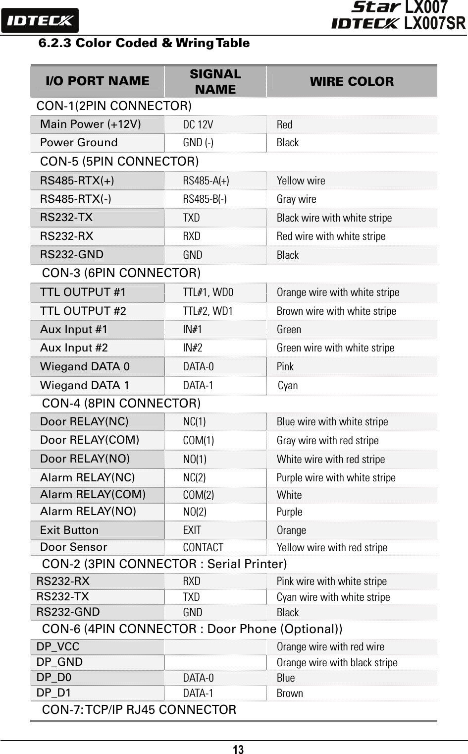
![12 6.2 Product Explanation 6.2.1 Panel Description Figure: Description of LX007 Front Panel • LCD Module: The LCD screen displays the status of the LX007. • System Operation Status LED: When the power is applied to the LX007, the red LED is turned on. When the Relay #1 operates, the green LED is turned on. When the Relay #2 operates, the yellow LED is turned on. • 24-key Keypad: The keypad can be used to manually operate the LX007 with ease. • Function Keys: The LX007 has 12 function keys ([F1] ~ [F12]). 6.2.2 Connection Layout Figure: Connector Layout 24-key Keypad (incl. 12 function keys) Fingerprint Scanner LCD Display System Operation Status LED CON-2CON-1 CON-6CON-3CON-4CON-5CON-7](https://usermanual.wiki/ID-Teck-Co/LX007.User-Manual-1-2/User-Guide-948884-Page-2.png)
![18 <1> KEY?“SYSTEM INITIALIZED!!!”Power ONInitialize OK?1: Yes 0: NoNormal OperationYesNoPress and hold the initialization button. Put the +12V DC power to the LX007. Release the button when the LCD displays “Initialize OK?”8.2 System Initialization (External Reader Port) After the installation and connections are completed, apply power (DC12V) to the LX007 with the initialization button held down. Then, the LCD will first display “Initialize OK? 0:No 1:Yes”. Press <1> key if you want to initialize the system. After all the initialization process is completed, the system will be operating in the normal mode and the LCD will display “IDTECK, LX007 [F1], Date Time”. 8.3 Wall Mount Installation 1. Position the Wall Mount to the location at which you want to install the unit and mark 4 x drilling positions. Drill 6-32 holes for at least 4 mounting points. 2. Drill a 1/2” hole on the center of the Wall Mount. 3. Using 4 screws, install the Wall Mount to the proper location. 4. Take out the cable through the center hole. 5. After the wiring is done as explained in the next section, put the Main Unit on the Wall Mount and screw it. 8.4 Wiring 8.4.1 Power Connection 1. Connect (+) wire of DC 12V Power Supply to Red wire. 2. Connect GND (-) wire of DC 12V Power Supply to Black wire. 8.4.2 Input Connection Exit Button Connection 1. Connect one wire from an Exit Button to Orange wire. 2. Connect the other wire from the Exit Button to GND.](https://usermanual.wiki/ID-Teck-Co/LX007.User-Manual-1-2/User-Guide-948884-Page-8.png)
![19 Door Contact Sensor Connection 1. Connect one wire from Door Contact Sensor to Yellow wire with Red stripe. 2. Connect the other wire from Door Contact Sensor to GND. Auxiliary Input Connection (Applicable to Aux Input #1(Green wire), Aux Input #2(Green wire with white stripe)) 1. Connect one wire from Auxiliary Input Device to one of Aux Input #1 or Aux Input #2. 2. Connect the other wire from Auxiliary Input Device to GND. Figure: Input Device Connection 2.2K Resistor Connection for Cut Off Check You have to connect a 2.2K resistor between the input wire (e.g. Orange wire) and the GND to apply the Cut Off Check feature. First, select whether or not to check the cutoff status of each device from [F5 SETUP MENU] -> Cut Off Check. Second, set the desired output that will be generated in the event of a cutoff from [F5 SETUP MENU] -> Cut Off Alarm. Figure: 2.2K Resistor Connection for Cut Off Check](https://usermanual.wiki/ID-Teck-Co/LX007.User-Manual-1-2/User-Guide-948884-Page-9.png)
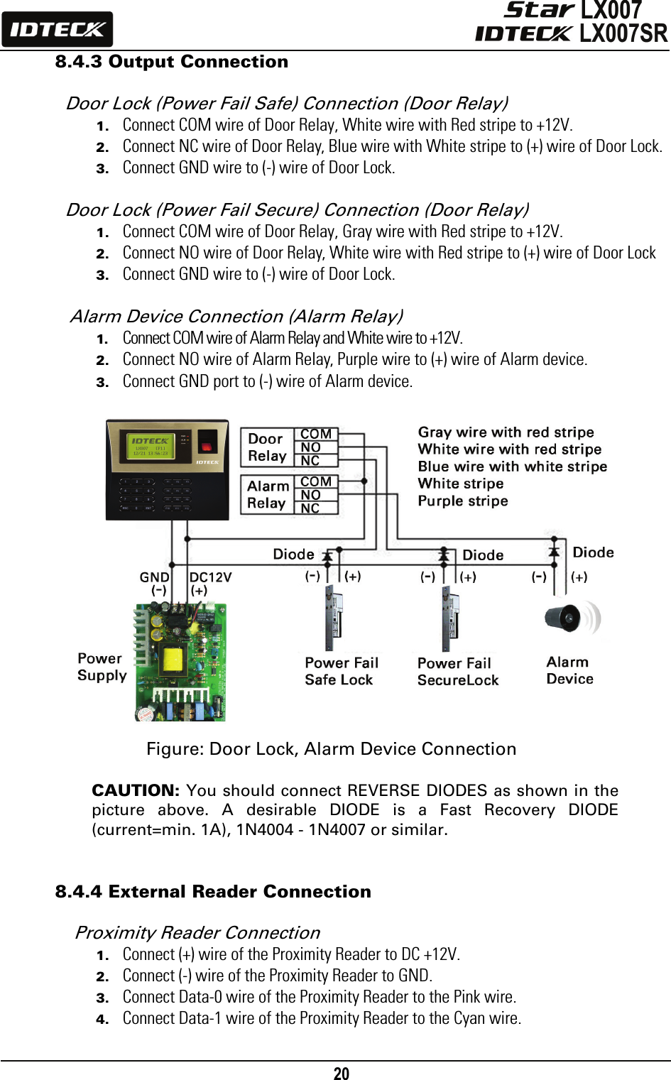
![24 9.3 TCP/IP Communication Port Connection (Optional) An optional TCP/IP Module is needed for TCP/IP communication to the host PC. Follow the next instruction. 1. Connect RJ45 plug, LAN cable of the network system to RJ45 jack of the LX007. 2. If you install multiple LX007 units and only one TCP/IP port is available, you may connect one LX007 to TCP/IP and then connect all the LX007 units using the RS485 multiple communication as shown in the below figure. 3. Set different COMM IDs for each LX007. 4. Install and run the LX007 Application Software. Figure: TCP/IP Communication between Multiple LX007 units and a host PC 9.4 Serial Printer Connection A 9-pin connector (Serial communication connector, female) is needed to connect the LX007 with a serial printer via RS232 communication. Please follow the steps below. 1. Connect RS232-TX, Cyan wire with white stripe to the pin #2 (RXD) of the 9-pin connector. 2. Connect RS232-RX, Pink wire with white stripe to the pin #3 (TX) of the 9-pin connector. 3. Connect GND, Black wire to the pin #5 of the 9-pin connector. 4. Plug in the 9-pin female connector to COM1 or COM2 Port of the serial printer. 5. Set the Print Output setting to ‘Auto Print’ or ‘Manual Print’ from [F3 SETUP MENU].](https://usermanual.wiki/ID-Teck-Co/LX007.User-Manual-1-2/User-Guide-948884-Page-14.png)
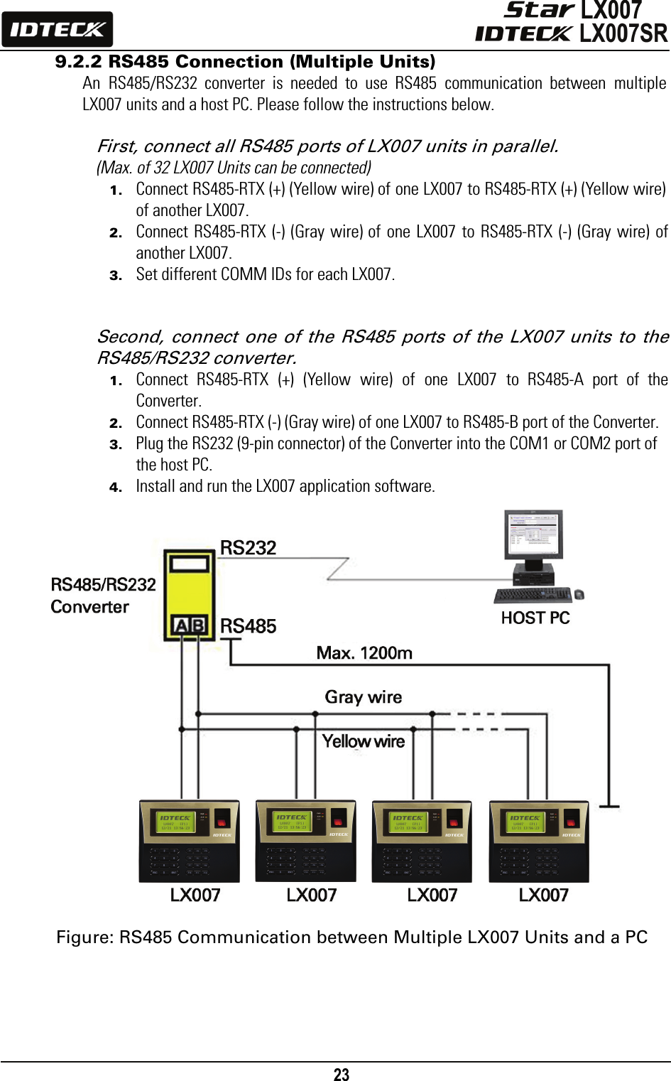
![25 <1> KEY?“SYSTEM INITIALIZED!!!”Power ONInitialize OK?1: Yes 0: NoNormal OperationYesNoPress and hold the initialization button. Put the +12V DC power to the LX007. Release the button when the LCD displays “Initialize OK?” Figure: RS232 Communication between LX007 and a Serial Printer 10. Basic Setting 10.1 Initialization of LX007 After the installation and connections are completed, supply power (DC +12V) to the LX007 with the initialization button held down. Then, the LCD will first display “Initialize OK? 0:No 1:Yes”. Press <1> key if you want to initialize the system. After all the initialization process is completed, the system will be operating on the normal mode and the LCD will display “IDTECK, LX007 [F1], Date Time”.](https://usermanual.wiki/ID-Teck-Co/LX007.User-Manual-1-2/User-Guide-948884-Page-15.png)
![26 10.2 How to Enter the SETUP MENU To set up the LX007 or to change the settings, you have to enter the SETUP MENU first. To do so, press <0> key eight (or ten) times and <ENT> key on the keypad. (The Default Master ID is ‘00000000’. For the LX007SR, it’s ‘0000000000’.) There are 10 SETUP MENUS and you automatically enter [F1 SETUP MENU] first. You can move to other SETUP MENUS by pressing <F1> to <F10> keys. For example, if you want to go to [F2 SETUP MENU], then press <F2> key. To enter [F5 SETUP MENU], press <F5> key, and so on and on. There are several SUBMENUS inside each SETUP MENU and you can scroll up and down the SUBMENU by pressing <4> and <6> key. If you don’t press any key within 60 seconds or if you press <ESC> key, the LX007 will exit the SETUP MENU and return to the normal operating mode. You can change the Master ID in the [F7 SETUP MENU]. 10.3 Language Setting Select [LANGUAGE] in [F1 SETUP MENU] then press <ENT> key to select which language to use. The steps below show how to choose Chinese, for example.](https://usermanual.wiki/ID-Teck-Co/LX007.User-Manual-1-2/User-Guide-948884-Page-16.png)
![27 10.4 Date / Time Setting Select [SET DATE/TIME] in [F1 SETUP MENU] and enter the total of 15 digits (i.e. Year / Month / Date / Hour / Minute / Second / Day) as shown below. The LCD will display the new Date and Time after the time setting is completed, but the year and day will not be displayed. The LX007 has a 24 hours system. Day codes are 1 for Sunday, 2 for Monday, 3 for Tuesday, 4 for Wednesday, 5 for Thursday, 6 for Friday and 7 for Saturday. 10.5 ID Registration To register a User ID to the LX007, select [F7 SETUP MENU] -> [REGISTRATION]. You can choose to register an ID a) using the card or b) by entering the PIN. a) Registration by Card](https://usermanual.wiki/ID-Teck-Co/LX007.User-Manual-1-2/User-Guide-948884-Page-17.png)
![28 b) Registration Using Keypad NOTE| In case you make a typing mistake during the registration process, you can press the F1 button to erase the errors. 1. Scanning – means the reader is waiting for an ID number to be entered. The number of the card will appear with a beep sound when you present a card. 2. ID – refers to a Personal Identification Number (PIN) that consists of 4-8 digits. Enter a 4-8 digit ID number (PIN) and press <ENT> key. (An ID number of the LX007SR consists of 4-10 digits.) 3. PW – stands for a password that is required for verification in the RF + Password operating mode. 4. TA – refers to the Time Schedule code (‘00’ ~ ‘10’) for the Reader#1 (i.e. the built-in reader). Cardholders are granted access only during the Time Intervals of the Time Schedule code entered to this TA field. To set the Time Intervals for each Time Schedule code, refer to the instructions on the Time Schedule Setup in the [F4 SETUP MENU]. If you want to allow the cardholder access to the door anytime, enter the default Time Schedule code '00' for the value. 5. TB – refers to the Time Schedule code (‘00’ ~ ‘10’) for the Reader#2 (i.e. Exit Reader). Cardholders are granted access only during the Time Intervals of the Time Schedule code entered to this TB field. To set the Time Intervals for each Time Schedule code, refer to the instructions on the Time Schedule Setup in the [F4 SETUP MENU]. If you want allow the cardholder access to the door anytime, enter the default Time Schedule code '00' for the value. 6. RD – refers to the Reader Assignment code for the cardholder. Entering the code ‘0’](https://usermanual.wiki/ID-Teck-Co/LX007.User-Manual-1-2/User-Guide-948884-Page-18.png)