ID Teck Co LX505 RFID Card Reader User Manual LX505 English 070620
ID-Teck Co Ltd RFID Card Reader LX505 English 070620
UserManual.wiki
>
ID Teck Co
>
LX505 User Manual
User Manual
Navigation menu
Upload a User Manual
Namespaces
Wiki Guide
HTML
PDF
Info
Views
User Manual
Discussion / Help
Navigation
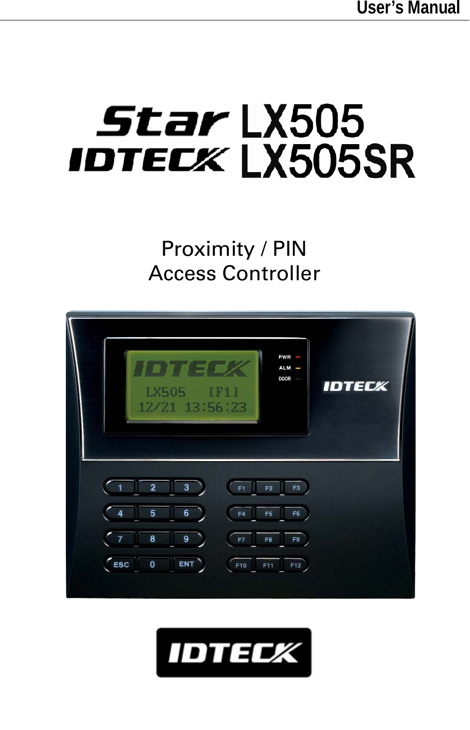
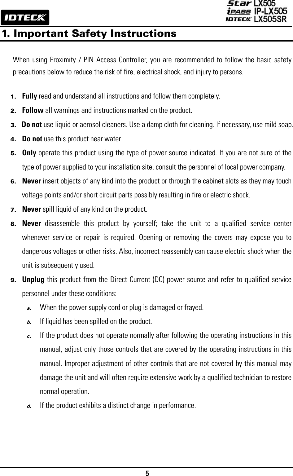
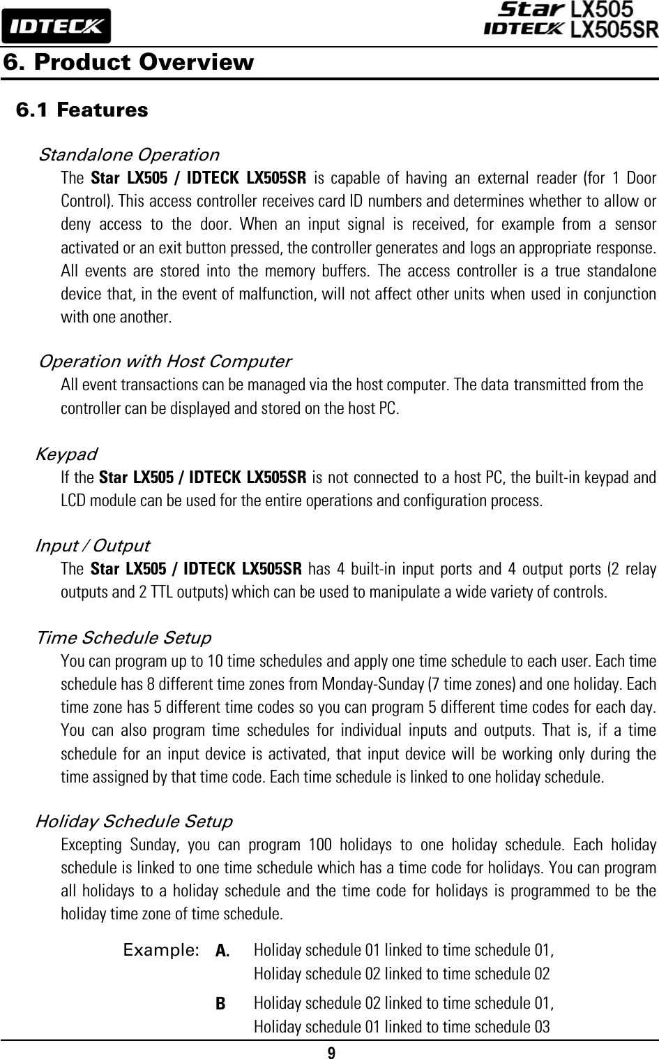
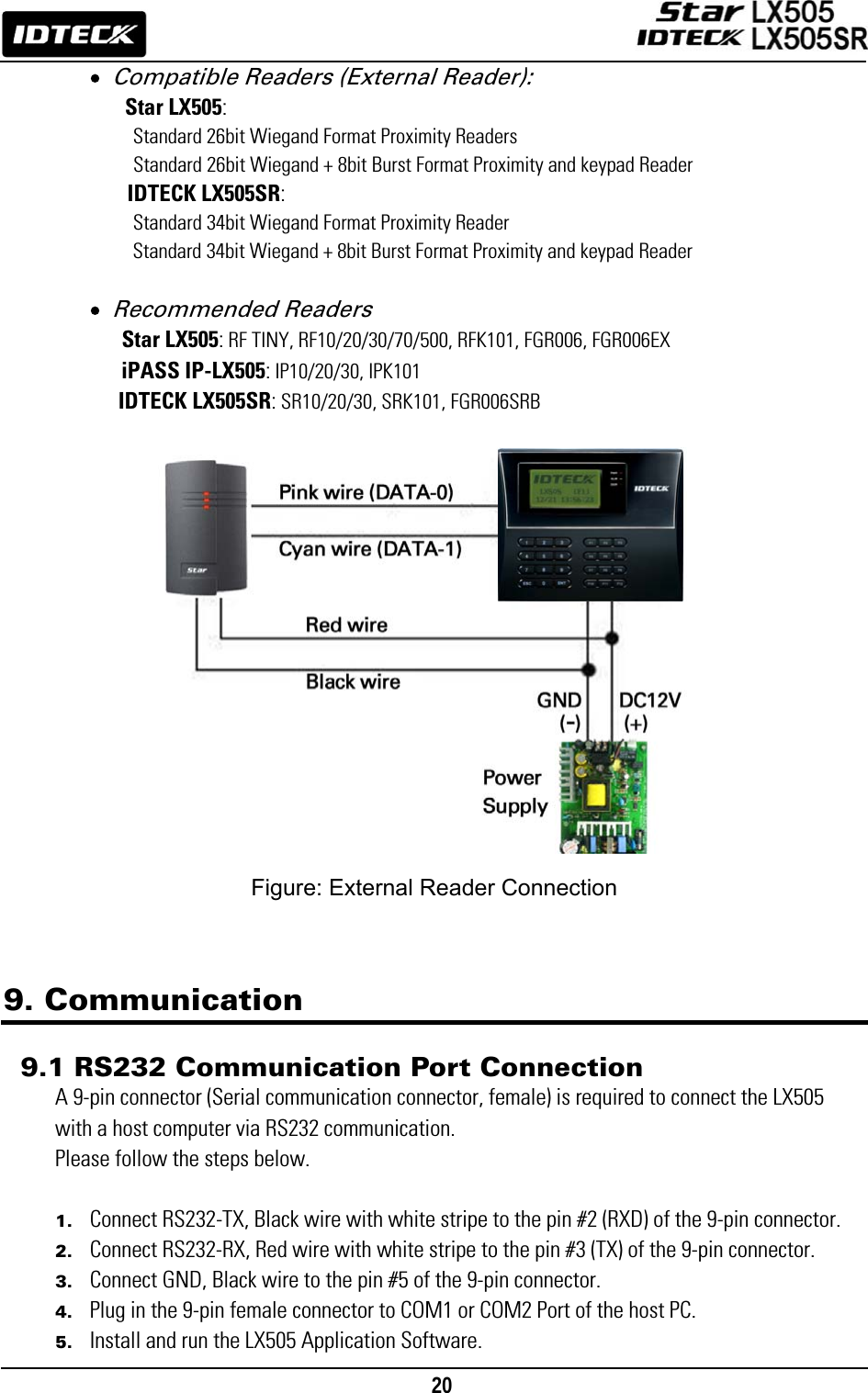
![11 6.2 Product Explanation 6.2.1 Panel Description Figure: Description of LX505 Front Panel • LCD Module: The LCD screen displays the status of the LX505. • System Operation Status LED: When the power is applied to the LX505, the red LED is turned on. When the Relay #1 operates, the green LED is turned on. When the Relay #2 operates, the yellow LED is turned on. • 24-key Keypad: The keypad can be used to manually operate the LX505 with ease. • Function Keys: The LX505 has 12 function keys ([F1] ~ [F12]). 6.2.2 Connection Layout Figure: Connector Layout 24-key keypad (incl. 12 function keys) LCD Display System Operation Status LED CNN-2CNN-1 CNN-6CNN-3CNN-4CNN-5CNN-7](https://usermanual.wiki/ID-Teck-Co/LX505/User-Guide-948900-Page-11.png)
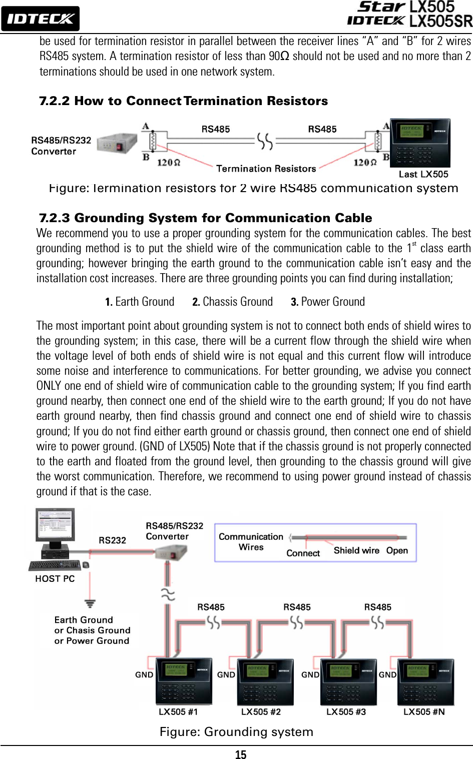
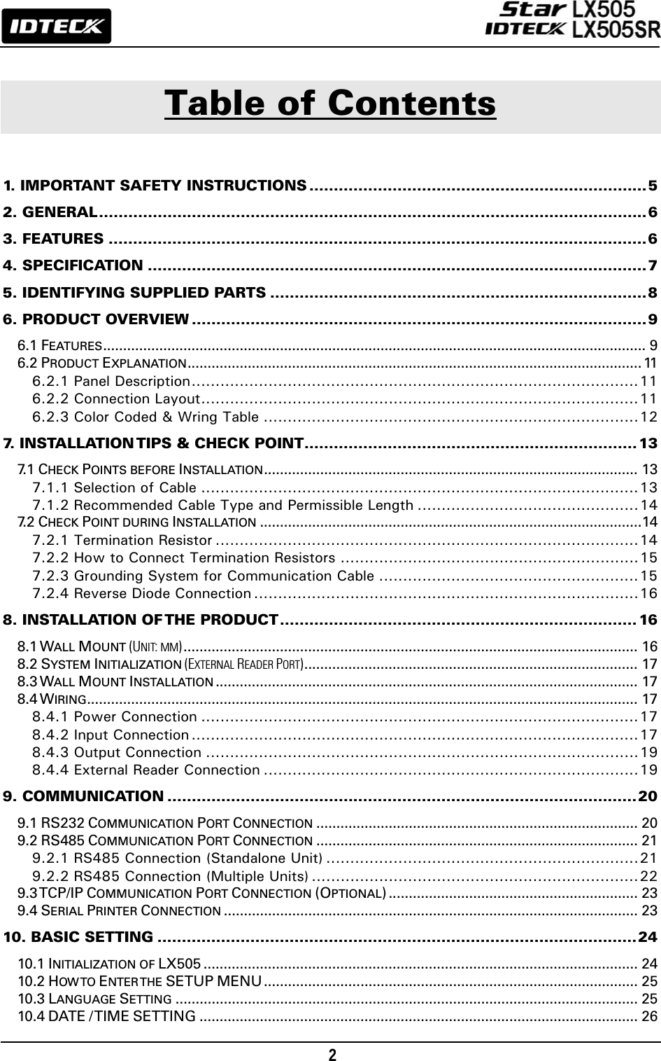
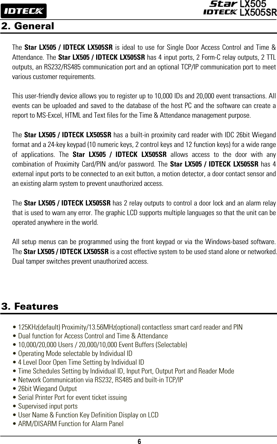
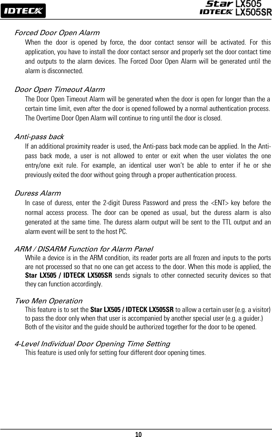
![17 <1> KEY?“SYSTEM INITIALIZED!!!”Power ONInitialize OK?1: Yes 0: NoNormal OperationYesNoPress and hold the initialization button. Put the +12V DC power to the LX007. Release the button when the LCD displays “Initialize OK?”8.2 System Initialization (External Reader Port) After the installation and connections are completed, apply power (DC12V) to LX505 with the initialization button being held down. Then, the LCD will first display “Initialize OK? 0:No 1:Yes”. Press <1> key if you want to initialize the system. After all the initialization process is completed, the system will be operating on the normal mode and the LCD will display “IDTECK, LX505 [F1], Date Time”. 8.3 Wall Mount Installation 1. Position the Wall Mount to the location at which you want to install the unit and mark 4 x drilling positions. Drill 6-32 holes for at least 4 mounting points. 2. Drill a 1/2” hole on the center of the Wall Mount. 3. Using 4 screws, install the Wall Mount to the proper location. 4. Take out the cable through the center hole. 5. After the wiring is done as explained in the next section, put the Main Unit on the Wall Mount and screw it. 8.4 Wiring 8.4.1 Power Connection 1. Connect (+) wire of DC 12V Power Supply to Red wire. 2. Connect GND (-) wire of DC 12V Power Supply to Black wire. 8.4.2 Input Connection Exit Button Connection 1. Connect one wire from Exit Button to Orange wire. 2. Connect the other wire from Exit Button to the GND.](https://usermanual.wiki/ID-Teck-Co/LX505/User-Guide-948900-Page-17.png)
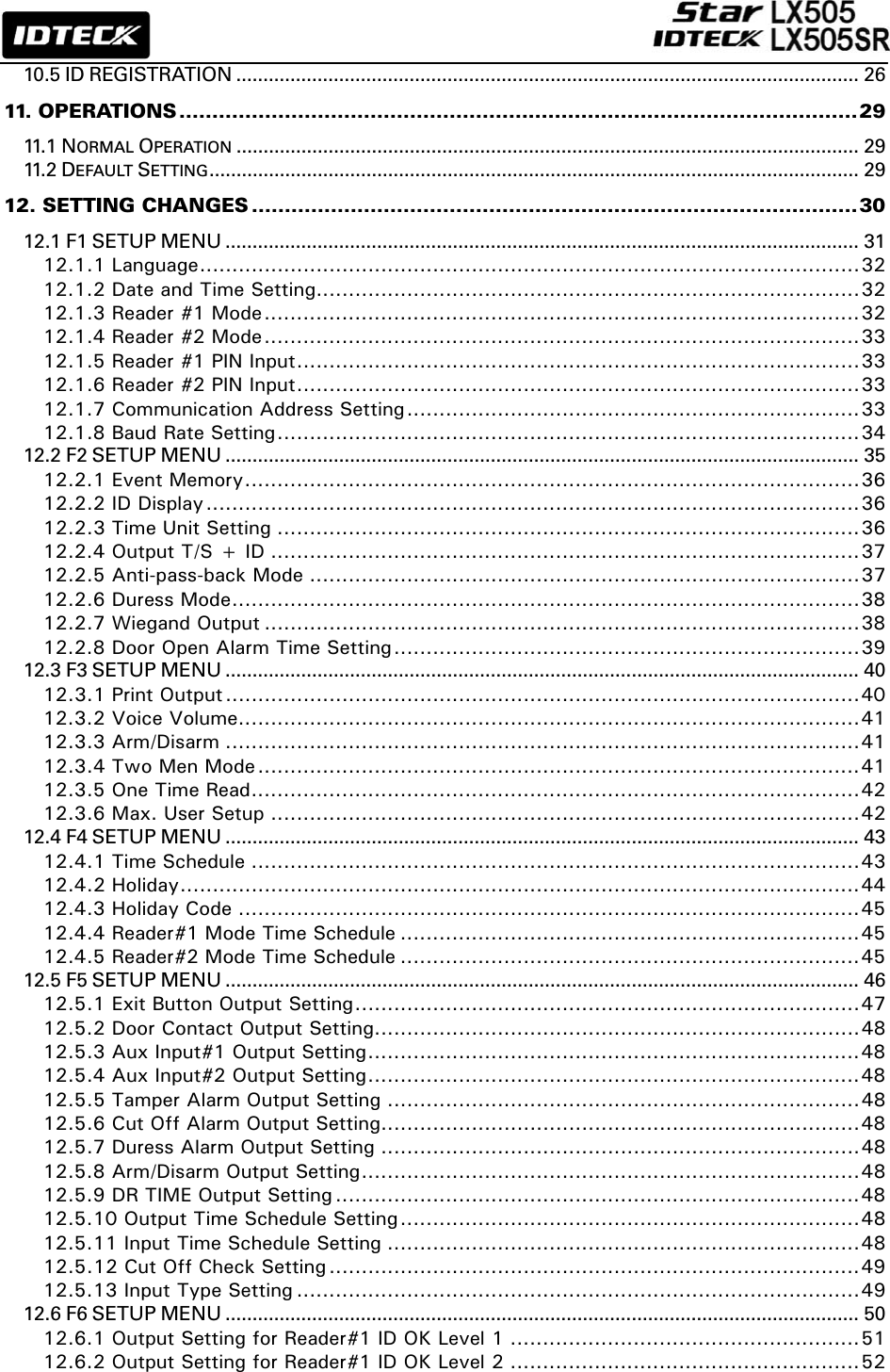
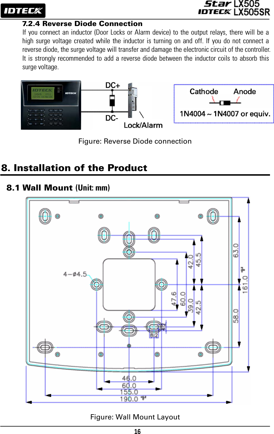
![18 Door Contact Sensor Connection 1. Connect one wire from Door Contact Sensor to Yellow wire with Red stripe. 2. Connect the other wire from Door Contact Sensor to GND. Auxiliary Input Connection (Applicable to Aux Input #1(Green wire), Aux Input #2(Green wire with white stripe)) 1. Connect one wire from Auxiliary Input Device to one of Aux Input #1 or Aux Input #2. 2. Connect the other wire from Auxiliary Input Device to GND. Figure: Input Device Connection 2.2K Resistor Connection for Cut Off Check You have to connect a 10K resistor between the input wire (e.g. Orange wire) and the GND to apply the Cut Off Check feature. First, select whether or not to check the cutoff status of each device from [F5 SETUP MENU] -> Cut Off Check. Second, configure the desired output that you want to be generated in the event of a cutoff from [F5 SETUP MENU] -> Cut Off Alarm. Figure: 2.2K Resistor Connection for Cut Off Check](https://usermanual.wiki/ID-Teck-Co/LX505/User-Guide-948900-Page-18.png)
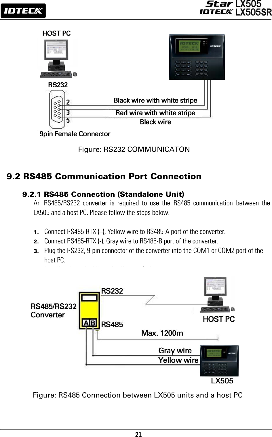
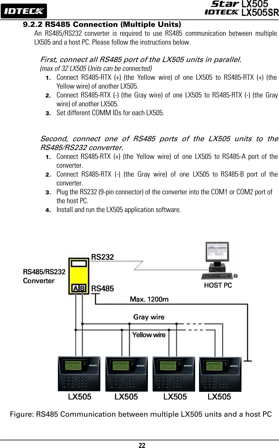
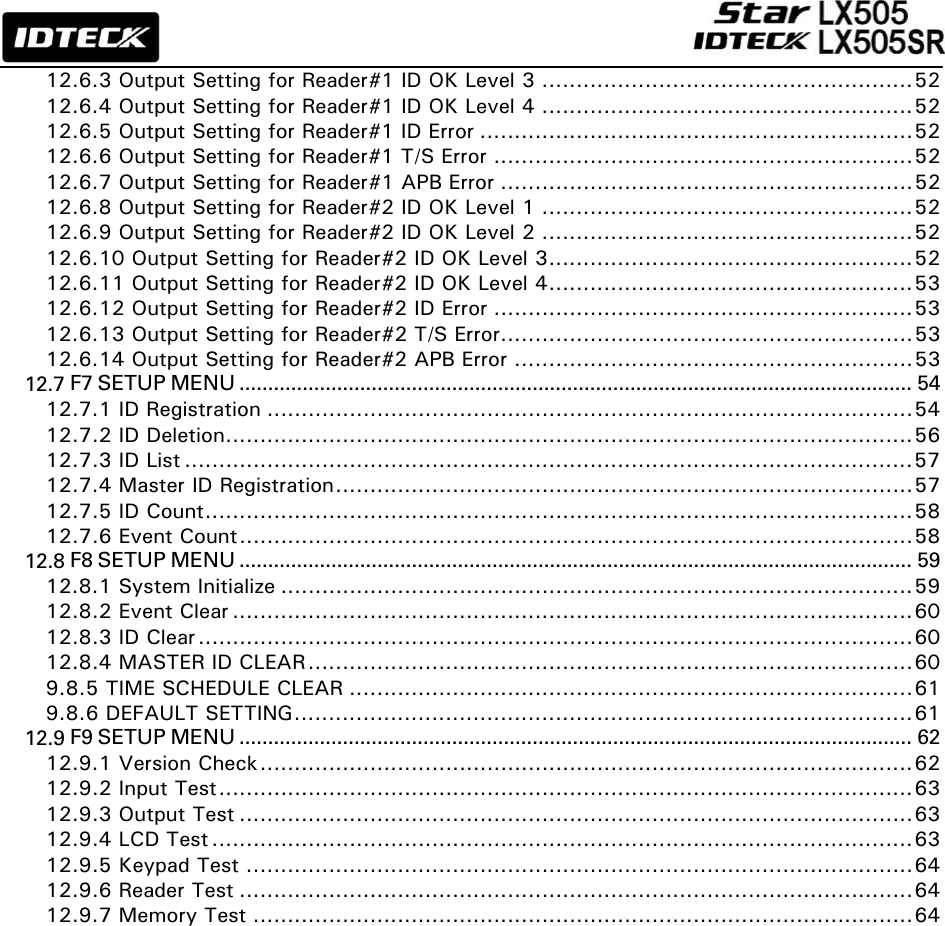
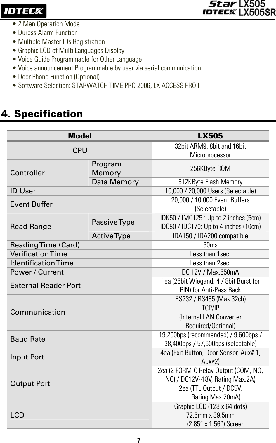
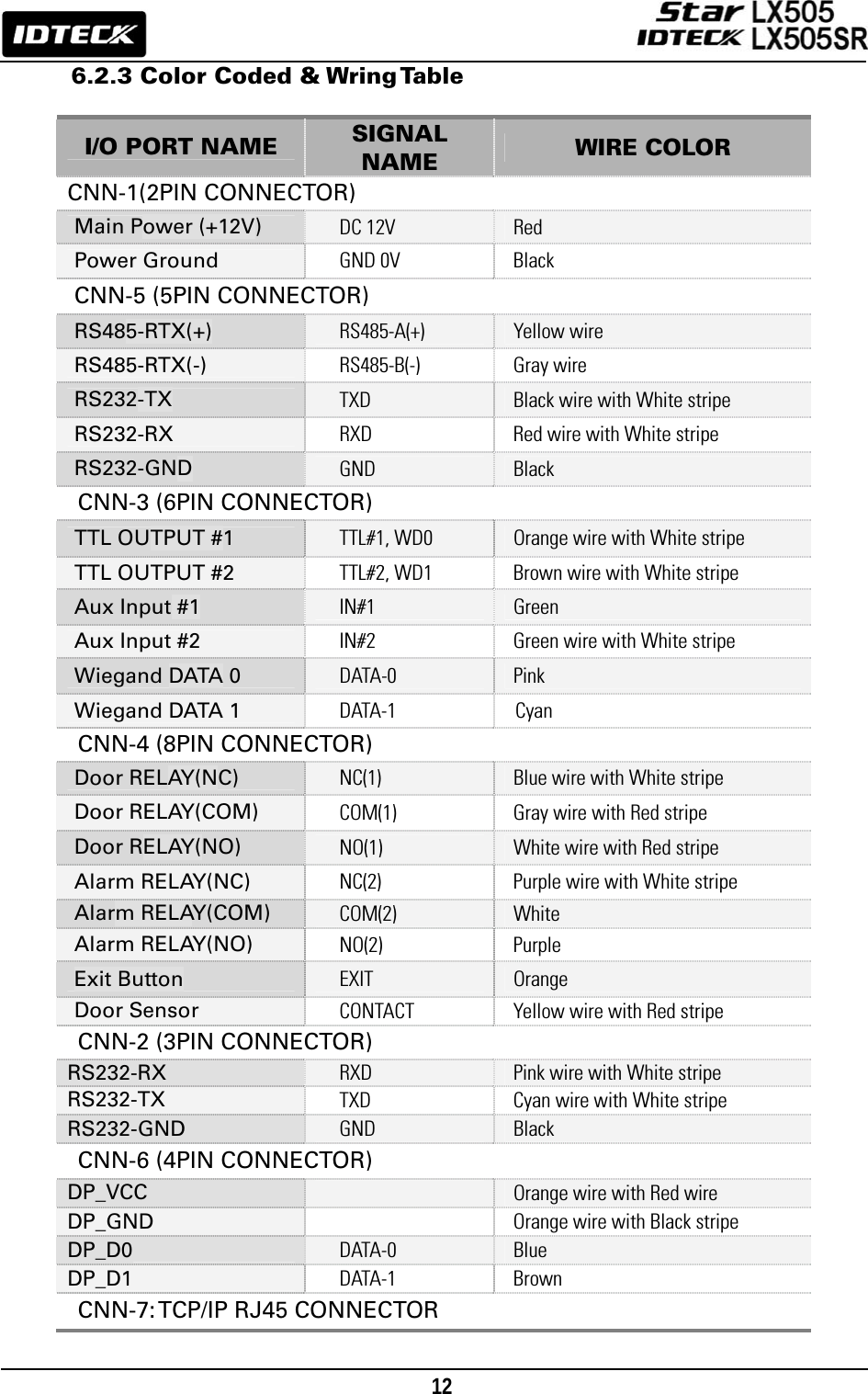
![23 9.3 TCP/IP Communication Port Connection (Optional) An optional TCP/IP Module is required for TCP/IP communication to the host PC. Follow the next instruction. 1. Connect RJ45 plug, LAN cable of the network system to RJ45 jack of the LX505. 2. If you install multiple LX505s and only one TCP/IP port is available, you may connect one LX505 to TCP/IP and then connect all the LX505s using the RS485 multiple communication as shown in the below figure. 3. Set different COMM IDs for each LX505. 4. Install and run the LX505 Application Software. Figure: TCP/IP Communication between multiple LX505 units and a host PC 9.4 Serial Printer Connection A 9-pin connector (Serial communication connector, female) is required to connect the LX505 with a serial printer via RS232 communication. Please follow the steps below. 1. Connect RS232-TX, Cyan wire with white stripe to the pin #2 (RXD) of the 9-pin connector. 2. Connect RS232-RX, Pink wire with white stripe to the pin #3 (TX) of the 9-pin connector. 3. Connect GND, Black wire to the pin #5 of the 9-pin connector. 4. Plug in the 9-pin female connector to COM1 or COM2 Port of the serial printer. 5. Set the Print Output setting to ‘Auto Print’ or ‘Manual Print’ from [F3 SETUP MENU].](https://usermanual.wiki/ID-Teck-Co/LX505/User-Guide-948900-Page-23.png)
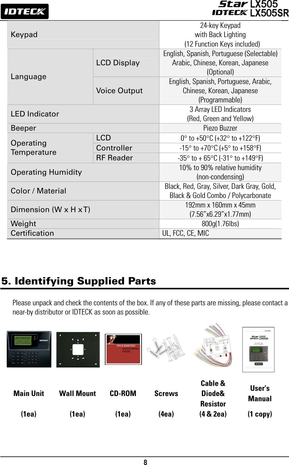
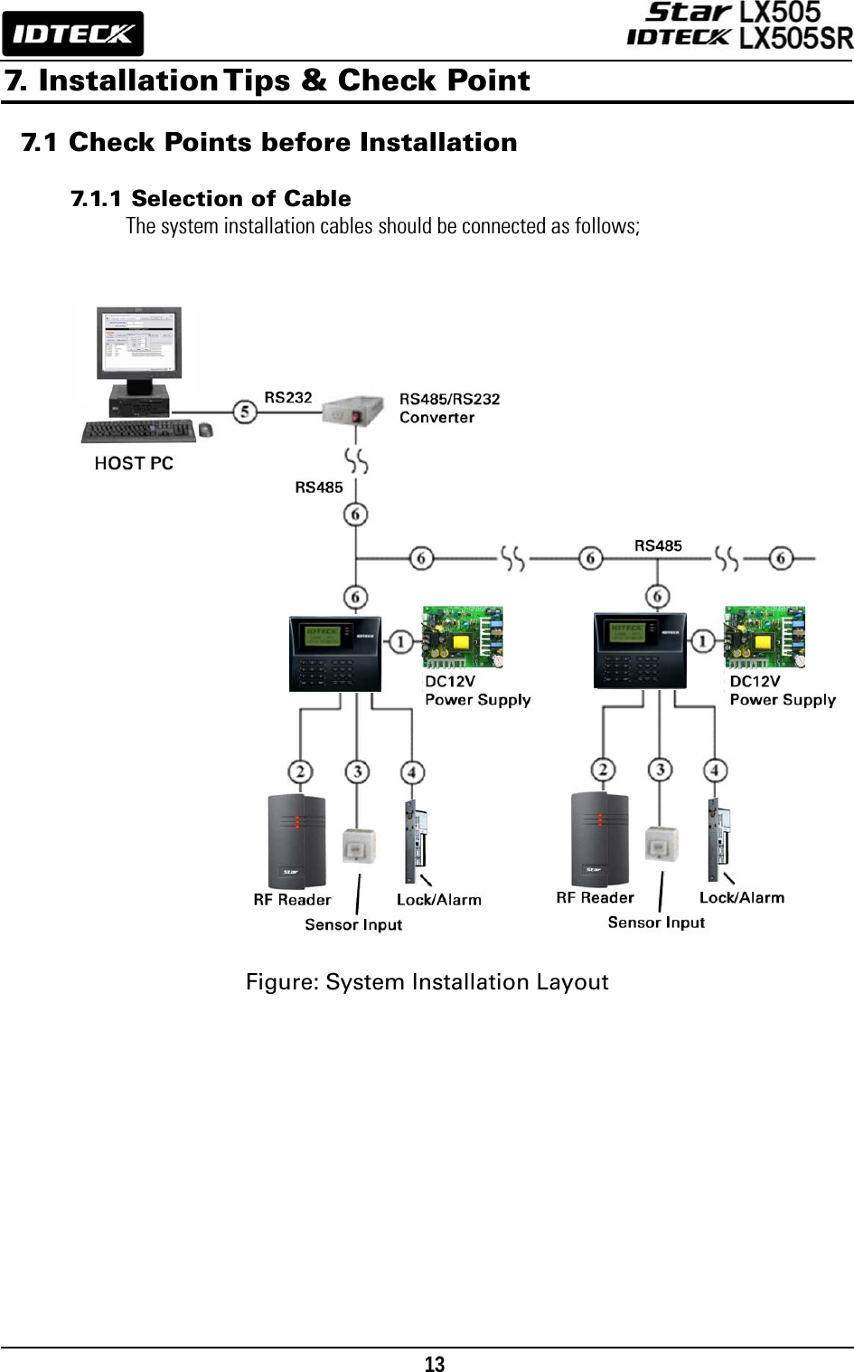
![24 <1> KEY?“SYSTEM INITIALIZED!!!”Power ONInitialize OK?1: Yes 0: NoNormal OperationYesNoPress and hold the initialization button. Put the +12V DC power to the LX505. Release the button when the LCD displays “Initialize OK?” Figure: RS232 Communication between the LX505 and a Serial Printer 10. Basic Setting 10.1 Initialization of LX505 After the installation and connections are completed, supply power (+12V DC) to LX505 with the initialization button being held down. Then, the LCD will first display “Initialize OK? 0:No 1:Yes”. Press <1> key if you want to initialize the system. After all the initialization process is completed, the system will be operating on the normal mode and the LCD will display “IDTECK, LX505 [F1], Date Time”.](https://usermanual.wiki/ID-Teck-Co/LX505/User-Guide-948900-Page-24.png)
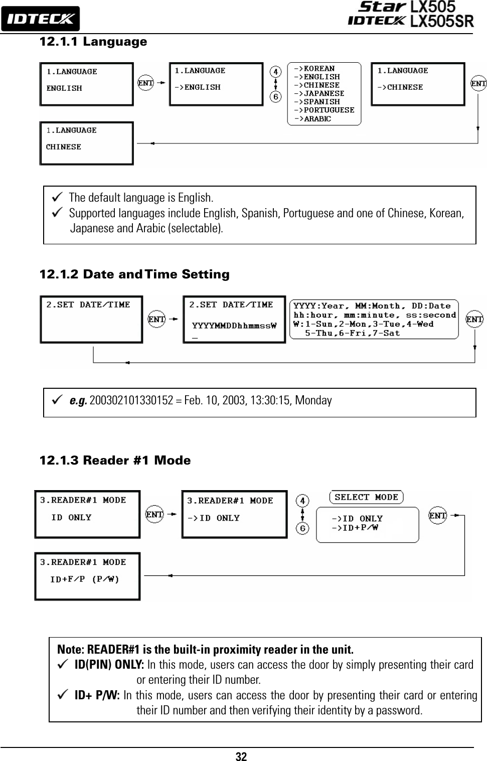
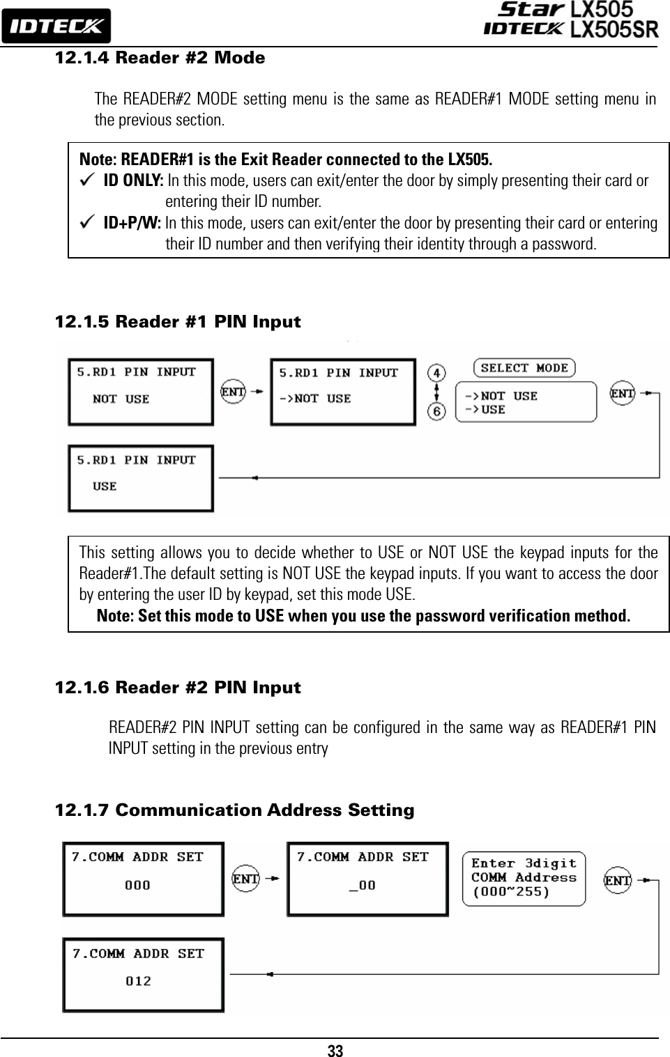
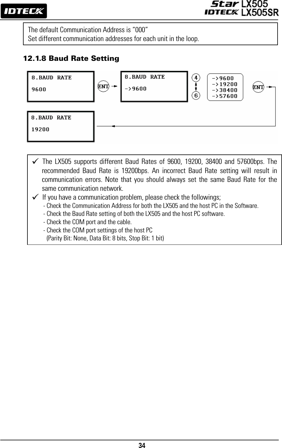
![25 10.2 How to Enter the SETUP MENU To set up the LX505 or to change the settings, you have to enter the SETUP MENU first. To do so, press <0> key eight (or ten) times and <ENT> key on the keypad. (The Default Master ID is ‘00000000’. For LX505SR, it’s ‘0000000000’.) There are 9 SETUP MENUS and you automatically [F1 SETUP MENU] first. You can move to other SETUP MENUS by pressing <F1> to <F9> keys. For example, if you want to go to [F2 SETUP MENU] then press <F2> key, to enter [F5 SETUP MENU], press <F5> key and so on and on. There are several SUBMENUS inside each SETUP MENU and you can scroll up and down the SUBMENU by pressing <4> and <6> key. If you don’t press any key within 60 seconds or if you press <ESC> key, the LX505 will exit the SETUP MENU and return to the normal operating mode. You can change the Master ID in the [F7 SETUP MENU]. 10.3 Language Setting Select [LANGUAGE] in the [F1 SETUP MENU] then press <ENT> key to select which LANGUAGE to use. The steps below show how to choose CHINESE, for example.](https://usermanual.wiki/ID-Teck-Co/LX505/User-Guide-948900-Page-25.png)
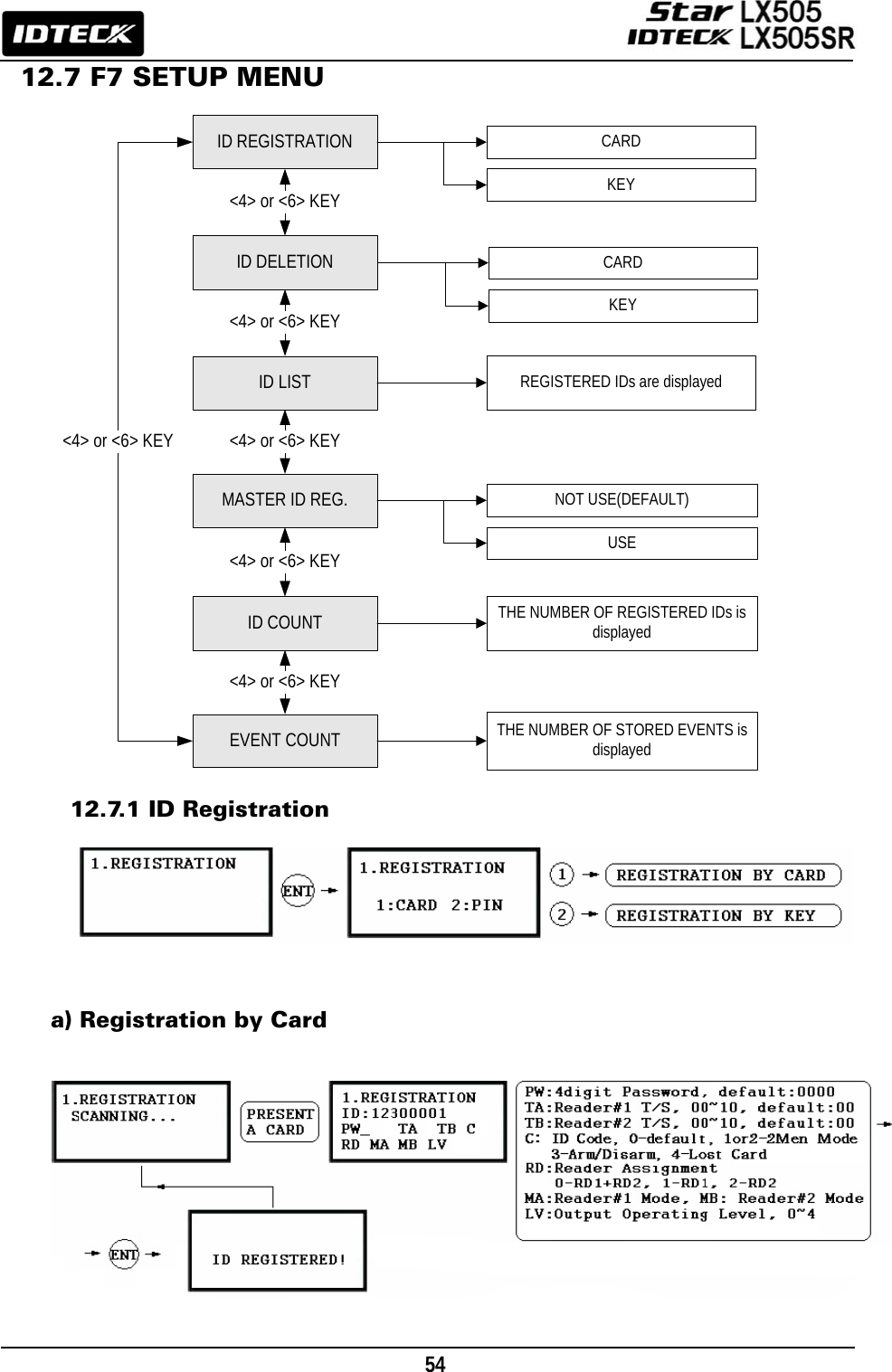
![26 10.4 DATE / TIME SETTING Select [SET DATE/TIME] in the [F1 SETUP MENU] and enter the total of 15 digits (i.e. Year / Month / Date / Hour / Minute / Second / Day) as shown below. The LCD will display the new Date and Time after the time setting is completed but the year and day will not be displayed. The LX505 has a 24 hours system. The day codes are 1 for Sunday, 2 for Monday, 3 for Tuesday, 4 for Wednesday, 5 for Thursday, 6 for Friday and 7 for Saturday. 10.5 ID REGISTRATION To register a User ID to the LX505, select [F7 SETUP MENU] -> [REGISTRATION]. You can choose to register an ID a) using the card or b) by entering the PIN. a) Registration by Card](https://usermanual.wiki/ID-Teck-Co/LX505/User-Guide-948900-Page-26.png)
![27 b) Registration Using Keypad NOTE| In case you make a typing mistake during the registration process, you can press F1 button to erase your errors. 1. Scanning – means the reader is waiting for an ID number to be entered. The card number for the card will appear with a beep sound when you present the card. 2. ID – is a Personal Identification Number (PIN) that consists of 4-8 digits. Enter a 4-8digit ID number (PIN) and press <ENT> key. (For LX505SR, the ID number consists of 4-10 digits. 3. PW – stands for a password that is required for verification in the RF + Password operating mode. 4. TA – refers to the Time Schedule code (‘00’ ~ ‘10’) for the Reader#1 (i.e. the built-in reader). Cardholders are granted access only during the Time Intervals of the Time Schedule code entered to this TA field. To set the Time Intervals for each Time Schedule code, refer to the instructions on the Time Schedule Setup in the [F4 SETUP MENU]. If you want allow the cardholder access to the door anytime, then enter the default Time Schedule code '00' for the value. 5. TB – refers to the Time Schedule code (‘00’ ~ ‘10’) for the Reader#2 (i.e. Exit Reader). Cardholders are granted access only during the Time Intervals of the Time Schedule code entered to this TB field. To set the Time Intervals for each Time Schedule code, refer to the instructions on the Time Schedule Setup in the [F4 SETUP MENU]. If you want allow the cardholder access to the door anytime, then enter the default Time Schedule code '00' for the value. 6. RD – refers to the Reader Assignment code for the cardholder. Entering the code ‘0’ assigns both readers (Built-in Reader and Exit Reader) to grant access to the user that is being registered, code ‘1’ only assigns Reader#1 (Built-in Reader) and code ‘2’ assigns Reader#2 (Exit Reader). If you enter ‘1’ in the RD field(Only Reader#1 assigned) and try to exit through Reader#2 (Exit Reader) then LX505 generates an error message (“Access Door Error”) on the LCD display.](https://usermanual.wiki/ID-Teck-Co/LX505/User-Guide-948900-Page-27.png)
![28 7. C – stands for the ID code. Code ‘0’ is default and code ‘1’ or ‘2’ is a code used for the TWO MEN MODE. Code ‘3’ is used for the ARM/DISARM function and code ‘4’ is assigned for lost cards. 8. MA – refers to the Operating Mode of the Reader#1 (i.e. the built-in reader) for the cardholder. If you enter ‘1’ for MA, for example, Reader#1 will be operating always on RF Only Mode. • ‘0’ – System Operating Mode (Path: [F1 SETUP MENU] > [READER#1 MODE]) • ‘1’ – ID Only Mode • ‘2’ – ID + Password Mode 9. MB – refers to the Operating Mode of the Reader#2 (Exit Reader) for the cardholder. If you enter ‘1’ for MB, for example, Reader#2 will be operating always on RF Only Mode. • ‘0’ – System Operating Mode (Path: [F1 SETUP MENU] > [READER#1 MODE]) • ‘1’ – ID Only Mode • ‘2’ – ID + Password Mode 10. LV – refers to the Output Operating Level for the cardholder. Output operating time can be set for each user. To configure an Output operating time for each level, refer to the instructions on Output Setting in the [F6 SETUP MENU]. • ‘0’ or ‘1’ – Level #1 • ‘2’ – Level #2 • ‘3’ – Level #3 • ‘4’ – Level #4](https://usermanual.wiki/ID-Teck-Co/LX505/User-Guide-948900-Page-28.png)
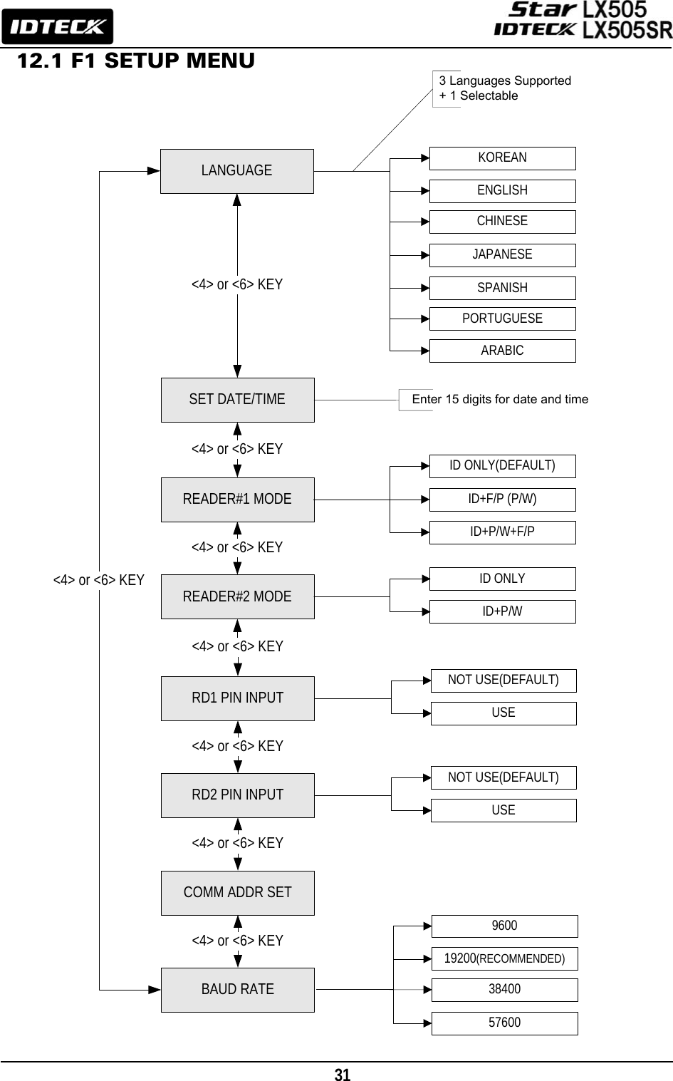
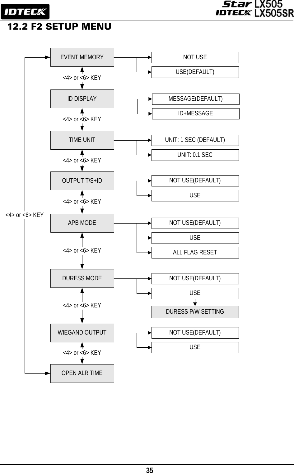
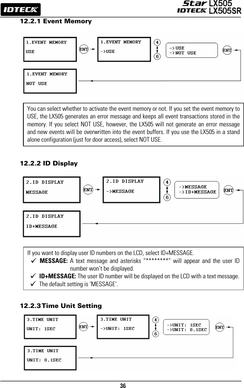
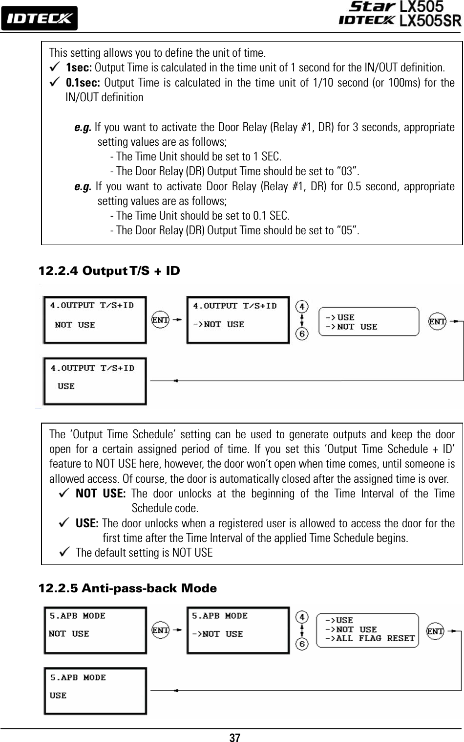
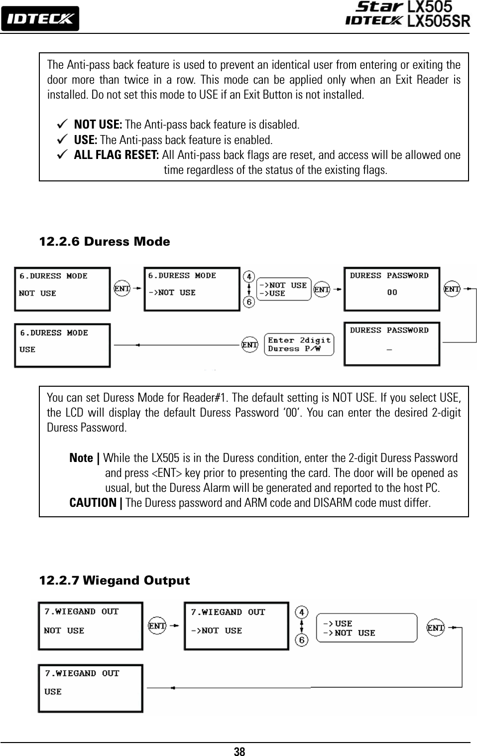
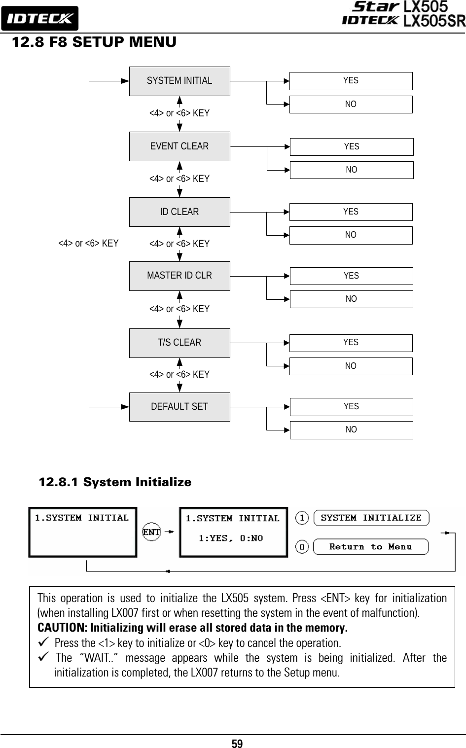
![30 12. Setting Changes To set up the LX505 or to change the settings, you have to enter the SETUP MENU first. To do so, press <0> key eight (or ten) times and <ENT> key on the keypad. (The Default Master ID is ‘00000000’. For LX505SR, it’s ‘0000000000’.) There are 9 SETUP MENUS and you automatically enter [F1 SETUP MENU] first. You can move to other SETUP MENUS by pressing <F1> to <F9> keys. For example, if you want to go to [F2 SETUP MENU] then press <F2> key, to enter [F5 SETUP MENU], press <F5> key and so on and on. There are several SUBMENUS inside each SETUP MENU and you can scroll up and down the SUBMENU by pressing <4> and <6> key. If you don’t press any key within 60 seconds or if you press <ESC> key, LX505 will exit the SETUP MENU and return to the normal operating mode. You can change the Master ID in the [F7 SETUP MENU]. INITIAL DISPLAY(MODEL NAME, CURRENT TIME)ID INPUT?MASTER ID /PW/FINGERPRINT ?YESYESNONORMAL OPERATIONS MODESETUP MODENOF1 SETUP MENUF2 SETUP MENUF3 SETUP MENUF4 SETUP MENUF5 SETUP MENUF6 SETUP MENUF7 SETUP MENUF8 SETUP MENUF9 SETUP MENU](https://usermanual.wiki/ID-Teck-Co/LX505/User-Guide-948900-Page-30.png)
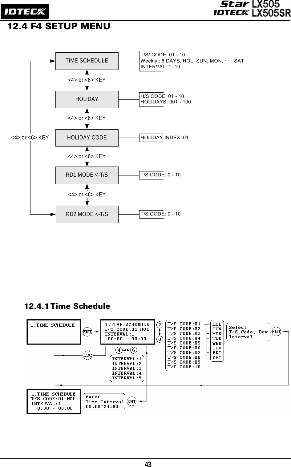
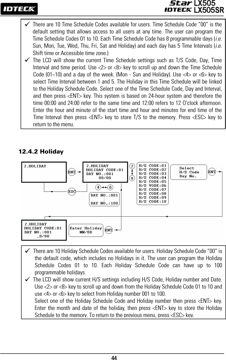
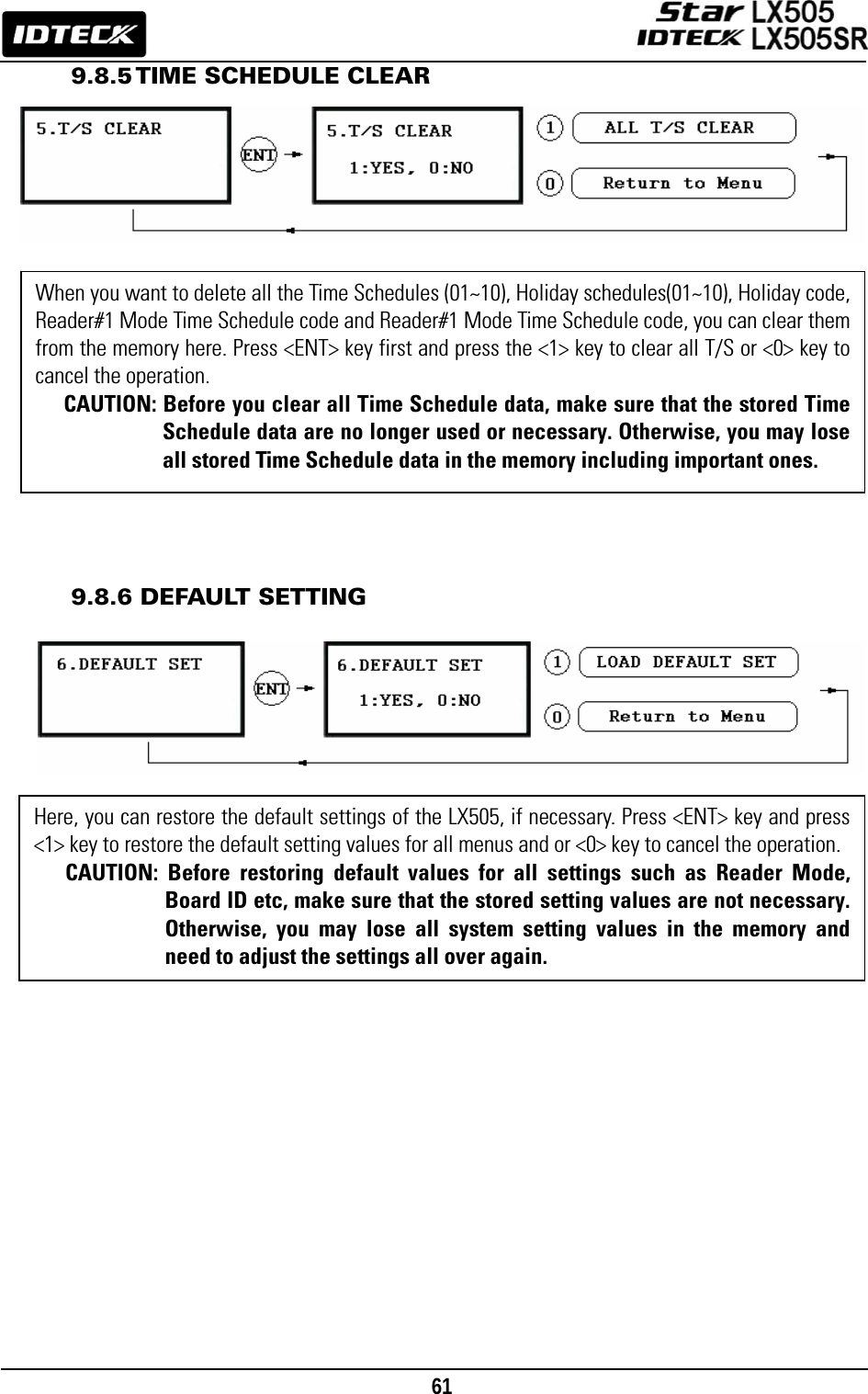
![45 12.4.3 Holiday Code 12.4.4 Reader#1 Mode Time Schedule 12.4.5 Reader#2 Mode Time Schedule The READER#2 MODE TIME SCHEDULE setting can be configured in the same way as READER#1 MODE T/S setting, which is explained in the previous section. The Holiday Code setting allows you to link a Holiday Schedule to a Time Schedule. A Time Schedule has 5 Time Intervals for holidays and the Time Intervals are applied only to the dates of this Holiday Schedule. The default Holiday Schedule Code is ‘00’ which means no holidays are applied to the Time Schedule. Use <4> or <6> key to scroll up and down from the T/S Code 01 to 10 and press <ENT> key. Then, enter a 2-digit Holiday Schedule Code and press <ENT> key to store the changed Holiday Index settings to the memory. To return to the previous menu, press <ESC> key. There are 2 system operations modes including RF Only Mode, RF+PW Mode. You can select one of these system operations modes at [R1 MODE SETTING] from [F1 SETUP MENU]. If, however, you want to apply a different operating mode to all users during a certain Time Interval. For example, you may want to access the door by only presenting a card from 09:00 to 17:00 and you want to use Password verification for the rest of the time. Then, you can to do so by setting [R1 MODE SETTING] to RF+PW Mode, which is for the system operating mode, and then program T/S Code 01 so it can include a Time Interval between 09:00 and17:00. Then link the Time Schedule Code 01 to the R1 MODE Time Schedule setting in this menu. To link a Time Schedule Code (01~10) to Reader#1 Mode, first, press <ENT> key and get into the setting mode. Then, enter the 2-digit Time Schedule Code and press <ENT> key to store and apply the Time Schedule Code to R1 MODE. To return to the previous menu, press <ESC> key.](https://usermanual.wiki/ID-Teck-Co/LX505/User-Guide-948900-Page-45.png)
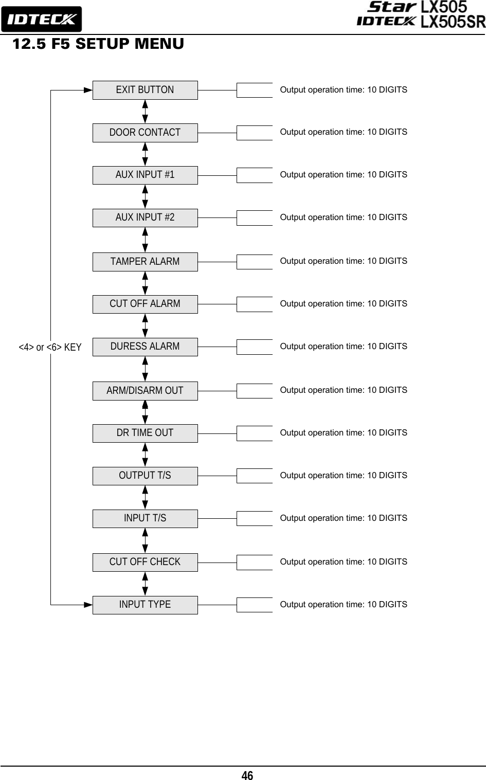
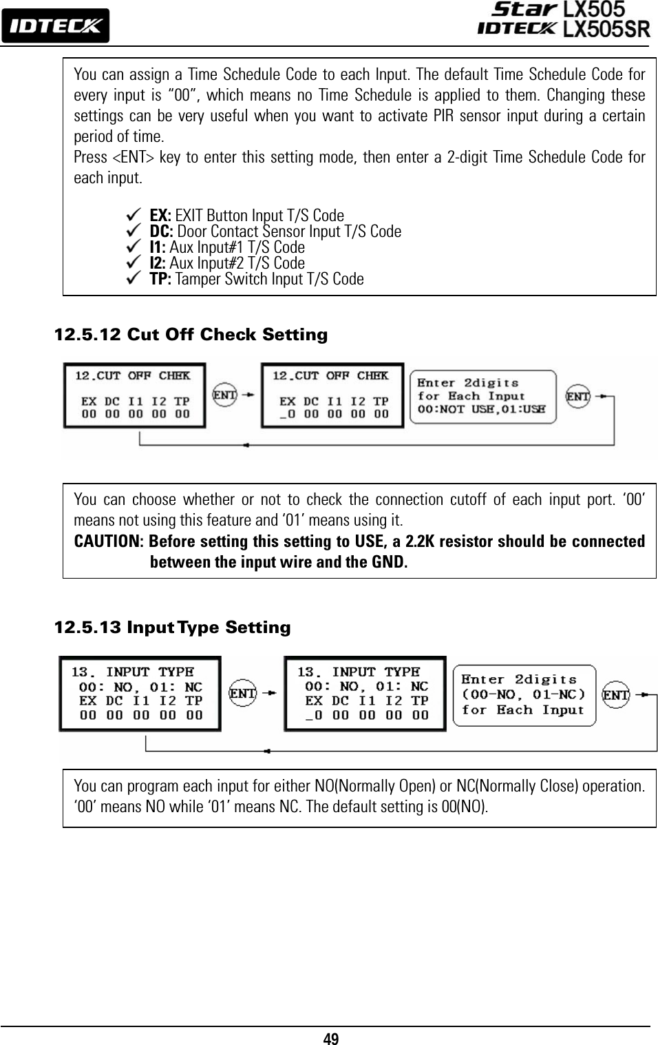
![47 Default Output Settings for Input Sources 12.5.1 Exit Button Output Setting OUTPUT Door Relay (DR) Alarm Relay (AR) TTL#1 (T1) TTL#2 (T2) Buzzer (BZ) [1] EXIT BUTTON 03 00 00 00 00 [2] DOOR CONTACT 00 99 00 00 00 [3] AUX Input #1 00 00 00 00 00 [4] AUX Input #2 00 00 00 00 00 [5] TAMPER ALARM 00 99 99 99 99 [6] CUT OFF ALARM 00 00 00 00 00 [7] DURESS ALARM 00 00 00 00 00 [8] ARM/DISARM OUT 00 00 00 00 00 [9] DR TIME OUT 00 00 00 00 00 [10] OUTPUT TIME SCHEDULE 00 00 00 00 00 [11] INPUT TIME SCHEDULE 00 00 00 00 00 [12] CUT OFF CHECK 00 00 00 00 00 [13] INPUT TYPE 00 00 00 00 00 You can program the Output Activation Time, the length of time forwhich the output is activated after the EXIT button is pressed. Let’s say, we put ‘03’ for one of the fields, If the unit of time is set to ‘1 sec’, then the activation time will be 3 seconds. If the unit of time is set to ‘0.1 sec’, then the activation time will be 0.3 seconds (or 300 ms.) You can set the time somewhere between 00 and 98 seconds (or between 0.0 and 9.8 seconds if the Time Unit is set to 0.1 sec.) If you put “99”, the corresponding output will be activated forever until you reset the output. DR: Door Relay Output AR: Alarm Relay Output T1: TTL#1 Output T2: TTL#2 Output BZ:Buzzer Output](https://usermanual.wiki/ID-Teck-Co/LX505/User-Guide-948900-Page-47.png)
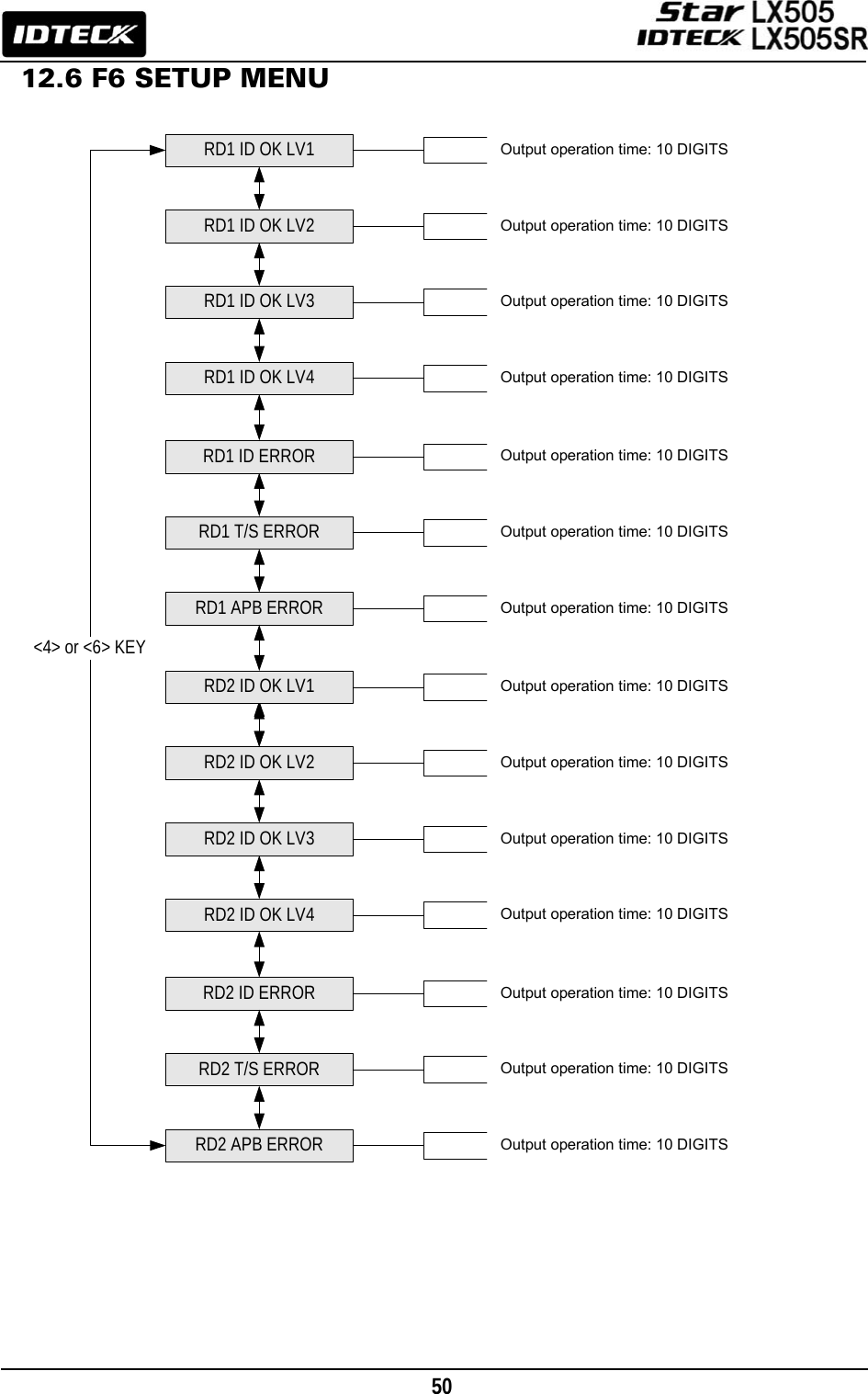
![51 Default Output Setting for Different Inputs 12.6.1 Output Setting for Reader#1 ID OK Level 1 OUTPUT Door Relay (DR) Alarm Relay (AR) TTL#1 (T1) TTL#2 (T2) Buzzer (BZ) [1] Reader#1 ID OK LV1 03 00 00 00 00 [2] Reader#1 ID OK LV2 05 00 00 00 00 [3] Reader#1 ID OK LV3 05 00 00 00 00 [4] Reader#1 ID OK LV4 05 00 00 00 00 [5] Reader#1 ID Error 00 03 00 00 00 [6] Reader#1 T/S Error 00 03 00 00 00 [7] Reader#1 APB Error 00 03 00 00 00 [8] Reader#2 ID OK LV1 03 00 00 00 00 [9] Reader#2 ID OK LV2 05 00 00 00 00 [10] Reader#2 ID OK LV3 05 00 00 00 00 [11] Reader#2 ID OK LV4 05 00 00 00 00 [12] Reader#2 ID Error 00 03 00 00 00 [13] Reader#2 T/S Error 00 03 00 00 00 [14] Reader#2 APB Error 00 03 00 00 00 You can program the Output Activation Time, the length of time during which the output is activated after the EXIT button is pressed. The actual Output Activation Time equals either V seconds, provided that the Time Unit is set to 1 second, or V/10 seconds, provided that the Time Unit is set to 0.1 second. (V=Activation Time Value assigned for each output.) You can set the time somewhere between 00 and 98 seconds (between 0.0 and 9.8 seconds if the Time Unit is set to 0.1 sec.) If you put “99”, the corresponding output will be activated forever until you reset the Output. DR: Door Relay Output AR: Alarm Relay Output T1: TTL#1 Output T2: TTL#2 Output BZ: Buzzer Output](https://usermanual.wiki/ID-Teck-Co/LX505/User-Guide-948900-Page-51.png)
![55 b) Registration Using Keypad NOTE| In case you make a typing mistake during the registration process, you can press F1 button to erase your errors. 1. Scanning – means the reader is waiting for an ID number to be entered. The card number for the card will appear with a beep sound when you present the card. 2. ID – is a Personal Identification Number (PIN) that consists of 4-8 digits. Enter a 4-8digit ID number (PIN) and press <ENT> key. (For LX505SR, the ID number consists of 4-10 digits. 3. PW – stands for a password that is required for verification in the RF + Password operating mode. 4. TA – refers to the Time Schedule code (‘00’ ~ ‘10’) for the Reader#1 (i.e. the built-in reader). Cardholders are granted access only during the Time Intervals of the Time Schedule code entered to this TA field. To set the Time Intervals for each Time Schedule code, refer to the instructions on the Time Schedule Setup in the [F4 SETUP MENU]. If you want allow the cardholder access to the door anytime, then enter the default Time Schedule code '00' for the value. 5. TB – refers to the Time Schedule code (‘00’ ~ ‘10’) for the Reader#2 (i.e. Exit Reader). Cardholders are granted access only during the Time Intervals of the Time Schedule code entered to this TB field. To set the Time Intervals for each Time Schedule code, refer to the instructions on the Time Schedule Setup in the [F4 SETUP MENU]. If you want allow the cardholder access to the door anytime, then enter the default Time Schedule code '00' for the value. 6. RD – refers to the Reader Assignment code for the cardholder. Entering the code ‘0’ assigns both readers (Built-in Reader and Exit Reader) to grant access to the user that is being registered, code ‘1’ only assigns Reader#1 (Built-in Reader) and code ‘2’ assigns Reader#2 (Exit Reader). If you enter ‘1’ in the RD field(Only Reader#1 assigned) and try to exit through Reader#2 (Exit Reader) then LX505 generates an error message (“Access Door Error”) on the LCD display.](https://usermanual.wiki/ID-Teck-Co/LX505/User-Guide-948900-Page-55.png)
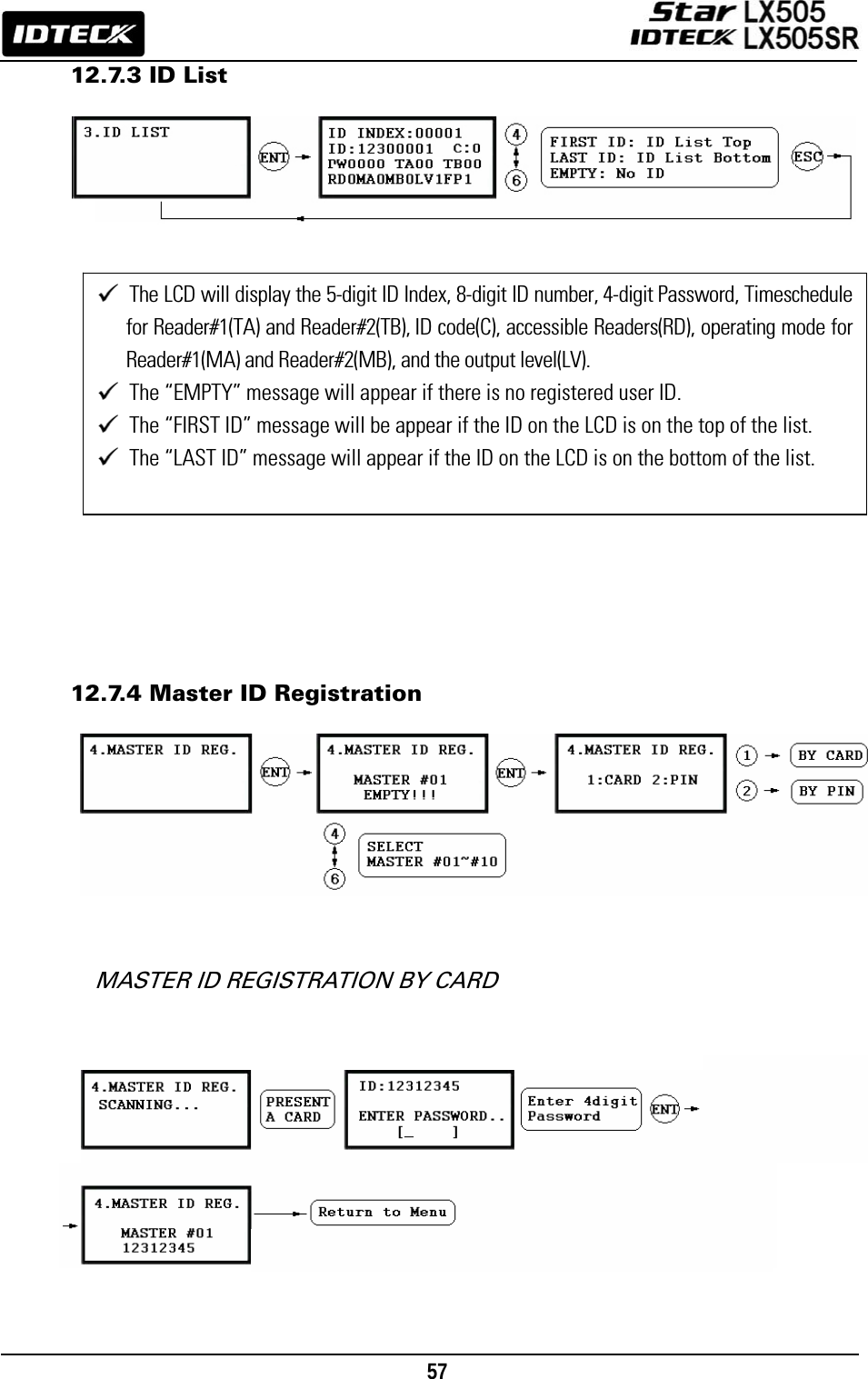
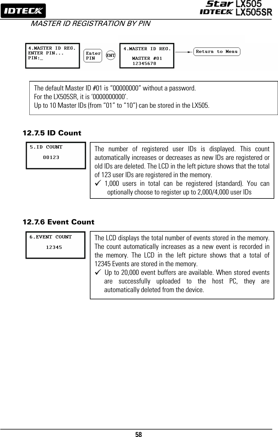
![56 7. C – stands for the ID code. Code ‘0’ is default and code ‘1’ or ‘2’ is a code used for the TWO MEN MODE. Code ‘3’ is used for the ARM/DISARM function and code ‘4’ is assigned for lost cards. 8. MA – refers to the Operating Mode of the Reader#1 (i.e. the built-in reader) for the cardholder. If you enter ‘1’ for MA, for example, Reader#1 will be operating always on RF Only Mode. • ‘0’ – System Operating Mode (Path: [F1 SETUP MENU] > [READER#1 MODE]) • ‘1’ – ID Only Mode • ‘2’ – ID + Password Mode 9. MB – refers to the Operating Mode of the Reader#2 (Exit Reader) for the cardholder. If you enter ‘1’ for MB, for example, Reader#2 will be operating always on RF Only Mode. • ‘0’ – System Operating Mode (Path: [F1 SETUP MENU] > [READER#1 MODE]) • ‘1’ – ID Only Mode • ‘2’ – ID + Password Mode 10. LV – refers to the Output Operating Level for the cardholder. Output operating time can be set for each user. To configure an Output operating time for each level, refer to the instructions on Output Setting in the [F6 SETUP MENU]. • ‘0’ or ‘1’ – Level #1 • ‘2’ – Level #2 • ‘3’ – Level #3 • ‘4’ – Level #4 • 12.7.2 ID Deletion Registered IDs can be deleted from the LX505 by presenting the card or entering the ID number. After entering the ID DELETION mode, present the card you want to delete. Alternatively, you may enter an 8 digit ID number and press <ENT> key from the keypad. The ID number will appear on the LCD and that ID will be removed from the device and the “ID DELETED” message will be shown on the LCD. If the ID number is not found, the “UNREGISTERED ID” message will appear. You can delete multiple IDs by repeating this process.](https://usermanual.wiki/ID-Teck-Co/LX505/User-Guide-948900-Page-56.png)
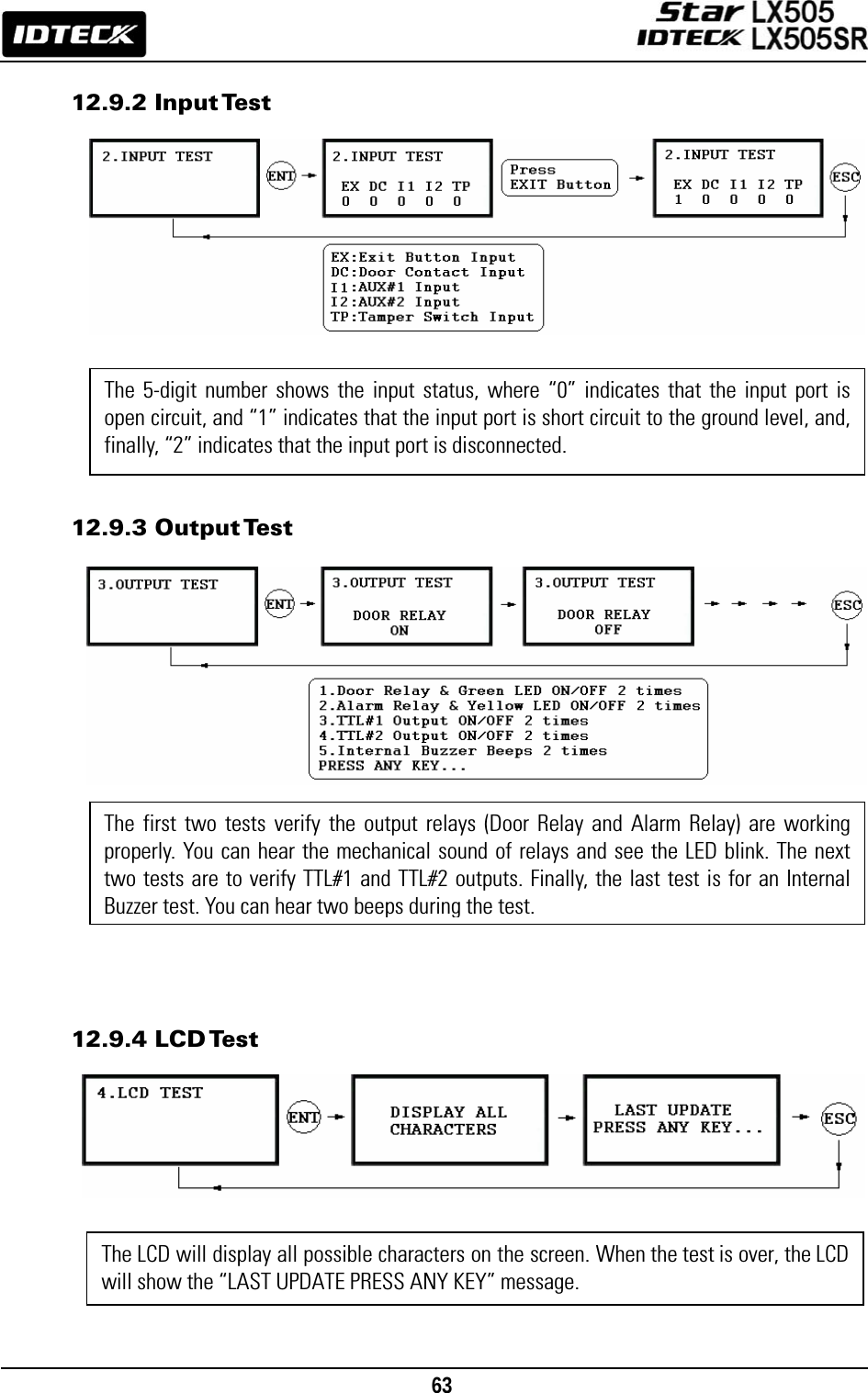
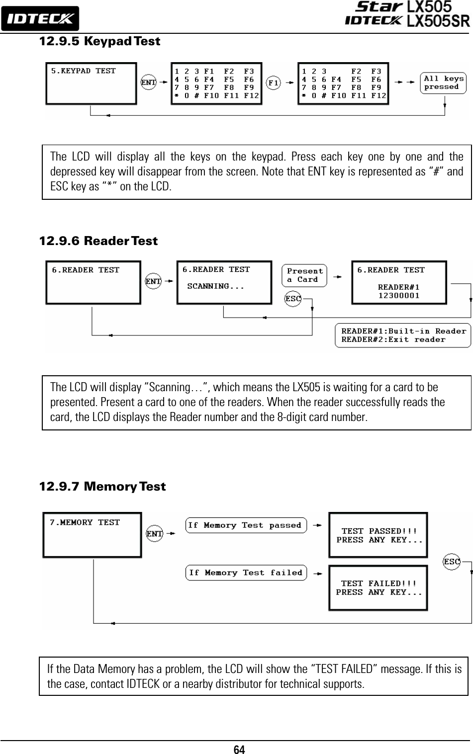
![62 The Firmware Version of the LX505 is displayed on the LCD.Press <4> or <6> key to take a look at other menus on [F9 SETUP MENU].12.9 F9 SETUP MENU 12.9.1 Version Check KEYPAD TESTREADER TEST<4> or <6> KEY<4> or <6> KEYFIRMWARE VER.INPUT TESTOUTPUT TEST<4> or <6> KEY<4> or <6> KEY<4> or <6> KEYLCD TEST<4> or <6> KEYTHE CURRENT VERSION OF FIRMWARE IS DISPLAYEDVERIFY THAT THE INPUT PORTS PROPERLY WORK.MEMORY TEST<4> or <6> KEYVERIFY THAT THE OUTPUT PORTS PROPERLY WORK.VERIFY THAT THE LCD SCREEN PROPERLY WORKS.VERIFY THAT ALL THE KEYS ON THE KEYPAD WORK.VERIFY THAT THE READER PROPERLY WORKS.VERIFY THAT THE MEMORY PROPERLY WORKS.](https://usermanual.wiki/ID-Teck-Co/LX505/User-Guide-948900-Page-62.png)
![65 APPENDIX A. THE RELATION BETWEEN INPUT AND OUTPUT (DEFAULT) Default Output Settings for Input Sources * Index No. [1] ~ [9] The values indicate the operating time (second) of each output for the input signal. * Index No. [10] The values indicate the time schedule code (index) applied to each output operation. * Index No. [11] The values indicate the time schedule code (index) applied to each input from #1(Exit button) to #5. * Index No. [12] The values indicate whether or not to use the cut off check feature. (0 – NOT USE, 1 – USE) * Index No. [12] The values indicate whether the input type is NO(Normally Open) or NC(Normally Closed). (0 – NO, 1 – NC) OUTPUT Door Relay (DR) Alarm Relay (AR) TTL#1 (T1) TTL#2 (T2) Buzzer (BZ) [1] EXIT BUTTON 03 00 00 00 00 [2] DOOR CONTACT 00 99 00 00 00 [3] AUX Input #1 00 00 00 00 00 [4] AUX Input #2 00 00 00 00 00 [5] TAMPER ALARM 00 99 99 99 99 [6] CUT OFF ALARM 00 00 00 00 00 [7] DURESS ALARM 00 00 00 00 00 [8] ARM/DISARM OUT 00 00 00 00 00 [9] DR TIME OUT 00 00 00 00 00 [10] OUTPUT TIME SCHEDULE 00 00 00 00 00 [11] INPUT TIME SCHEDULE 00 00 00 00 00 [12] CUT OFF CHECK 00 00 00 00 00 [13] INPUT TYPE 00 00 00 00 00](https://usermanual.wiki/ID-Teck-Co/LX505/User-Guide-948900-Page-65.png)
![66 Default Output Settings for Input Circumstance * Index No. [1] ~ [14]: The values indicate the operations time (second) of each output for the input signal. OUTPUT INPUT Door Relay (DR) Alarm Relay (AR) TTL#1 (T1) TTL#2 (T2) Buzzer (BZ) [1] Reader#1 ID OK LV1 03 00 00 00 00 [2] Reader#1 ID OK LV2 05 00 00 00 00 [3] Reader#1 ID OK LV3 05 00 00 00 00 [4] Reader#1 ID OK LV4 05 00 00 00 00 [5] Reader#1 ID Error 00 03 00 00 00 [6] Reader#1 T/S Error 00 03 00 00 00 [7] Reader#1 APB Error 00 03 00 00 00 [8] Reader#2 ID OK LV1 03 00 00 00 00 [9] Reader#2 ID OK LV2 05 00 00 00 00 [10] Reader#2 ID OK LV3 05 00 00 00 00 [11] Reader#2 ID OK LV4 05 00 00 00 00 [12] Reader#2 ID Error 00 03 00 00 00 [13] Reader#2 T/S Error 00 03 00 00 00 [14] Reader#2 APB Error 00 03 00 00 00](https://usermanual.wiki/ID-Teck-Co/LX505/User-Guide-948900-Page-66.png)
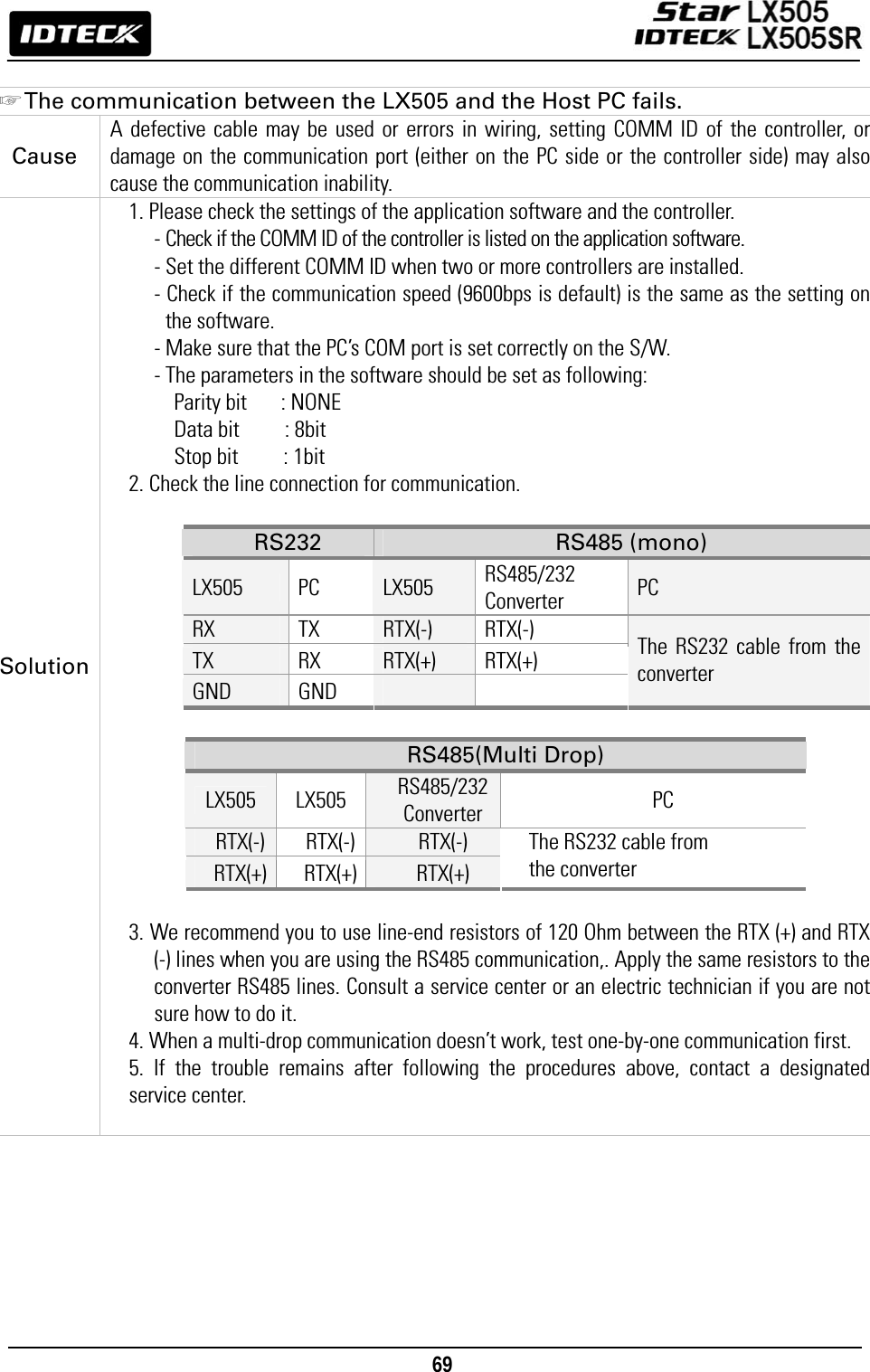
![67 B. TROUBLE SHOOTING ☞ A valid card became unregistered after batch-downloading IDs from PC. Cause Wrong download procedure or a component defect. Solution 1. The card ID might be registered only to the controller and not in the PC. During the process of batch-downloading IDs from the PC, LX505 first erases the ID memory in it. That’s why this deletion of certain IDs can happen if those IDs are not registered on the PC. 2. Check whether the card ID is registered in the PC. 3. If not, please register the number and try downloading again. 4. If the trouble remains after following the procedures above, contact a designated service center. ☞ I entered the Master ID “00000000” but I still cannot enter the Setup Mode. Cause The Master ID might have been changed or some components are defective. Solution 1. Try changing the Master ID through the application software. (The Master ID will be changed to the default value “00000000”.) 2. When it is not feasible, initialize the unit as following: After the installation and connections are completed, supply power (+12V DC) to LX505 with the initialization button being held down. Then, the LCD will first display “Initialize OK? 0:No 1:Yes”. Press <1> key if you want to initialize the system. After all the initialization process is completed, the system will be operating on the normal mode and the LCD will display “IDTECK, LX505 [F1], Date Time”. 3. If the trouble remains after following the procedures above, contact a designated service center. ☞ No problem with accessing by card, but cannot access via a manual PIN input. Cause An error in the settings or possible component defect. Solution 1. Check whether a beep sounds when you press a key. If a beep sounds, the problem may be wrong settings. Proceed as followings: - Enter the Master ID (Default=“00000000”) to get into the Setup mode. - Press <F2> key. - [LANGUAGE] will appear on the LCD, then use the <6> key to choose [RD1_PIN_INPUT] and press [ENT] key to modify the value to ‘USE’ by using <4> or <6> key. 2. When there is no beep sound or the problem persists after the keypad has been enabled, contact a designated service center. ☞ I suddenly go back from the Setup mode to the normal operations mode. Cause Time-out error Solution LX505 is originally programmed to go back to the normal operations mode when no keys are pressed or no cards are read within 60 seconds.](https://usermanual.wiki/ID-Teck-Co/LX505/User-Guide-948900-Page-67.png)
![68 ☞ The buzzer keeps beeping; “beep~ beep ~ beep” or “beeeeeeeep~~~~”. Cause An error in the Installation, Door status or Internal circuits. Solution 1. Check the door status. It occurs when the door is opened over 3 sec (Default). 2. Check the door contact sensor type: it must be NO/NC type. 3. Check the 10 Time schedule code (01~10) values of output T/S, in [7. OUTPUT T/S] of F6 Setup Menu. This problem can occur If the time schedule code is set between 01 and 10 or if the present time is in the schedule. If the time schedule is set to a unintended value, change it to “00” (Programmable via PC software) 4. Check the Tamper switch of LX505. 5. If the trouble remains after checking the above, contact a designated service center. ☞ The “SCHEDULE ERROR” message shows when RFID card is read. Cause An error in RFID card registration, time schedule setting or the system itself. Solution 1. If the LX505 used to be properly operating before, it is guessed that there has been an electric shock that damaged the internal memory and data. Please initialize the unit as instructed in the manual. 2. Check if the registered ID information has been configured incorrectly. * Register ID again and check the following points. - In order to restrict access of a user within a specific time zone as instructed in the manual, register time schedule in advance and apply the time schedule code(1~10) to the user during the registration process. - In order to allow the user to access at all times, put in “00”. 3. Use the software for time schedule settings if it LX505 is connected to PC as the software manual. 4. If the trouble remains after checking the above, contact a designated service center. ☞ The “ACCESS DOOR ERR” message shows when an RF ID card is read. Cause Incorrect user setting or something wrong with internal circuits. Solution 1. If the LX505 used to operate properly before, it is guessed that there has been an electric shock that damaged the internal memory and data. Please initialize the unit as instructed in the manual. 2. Check if ID information has been put in incorrectly during its registration. * Register ID again and check the following points: - Since the controller has two reader ports, set the “RD” setting – the door to which the user will be allowed access – to an appropriate value. - If the value for RD is set to “1”, the door opens only when Reader 1 reads a card. If the card is presented to Reader 2, the “ACCESS DOOR ERROR” message appears. - If the value for RD is set to “2”, the door opens only when Reader 2 reads a card. If the card is presented to Reader 1, the “ACCESS DOOR ERROR” message appears. - If RD is set to “0 or 3”, both the reader 1 and 2 open each door. 3. If the trouble remains after checking the above, contact a designated service center.](https://usermanual.wiki/ID-Teck-Co/LX505/User-Guide-948900-Page-68.png)