ID Teck Co LX505 RFID Card Reader User Manual LX505 English 070620
ID-Teck Co Ltd RFID Card Reader LX505 English 070620
User Manual
User’s Manual
Proximity / PIN
Access Controller

2
Table of Contents
1. IMPORTANT SAFETY INSTRUCTIONS .....................................................................5
2. GENERAL................................................................................................................6
3. FEATURES ..............................................................................................................6
4. SPECIFICATION ......................................................................................................7
5. IDENTIFYING SUPPLIED PARTS .............................................................................8
6. PRODUCT OVERVIEW .............................................................................................9
6.1 FEATURES....................................................................................................................................... 9
6.2 PRODUCT EXPLANATION................................................................................................................. 11
6.2.1 Panel Description.............................................................................................11
6.2.2 Connection Layout...........................................................................................11
6.2.3 Color Coded & Wring Table ..............................................................................12
7. INSTALLATION TIPS & CHECK POINT....................................................................13
7. 1 CHECK POINTS BEFORE INSTALLATION............................................................................................. 13
7.1.1 Selection of Cable ...........................................................................................13
7.1.2 Recommended Cable Type and Permissible Length ..............................................14
7. 2 CHECK POINT DURING INSTALLATION ...............................................................................................14
7.2.1 Termination Resistor ........................................................................................14
7.2.2 How to Connect Termination Resistors ..............................................................15
7.2.3 Grounding System for Communication Cable ......................................................15
7.2.4 Reverse Diode Connection ................................................................................16
8. INSTALLATION OF THE PRODUCT......................................................................... 16
8.1 WALL MOUNT (UNIT: MM)................................................................................................................. 16
8.2 SYSTEM INITIALIZATION (EXTERNAL READER PORT)................................................................................... 17
8.3 WALL MOUNT INSTALLATION ......................................................................................................... 17
8.4 WIRING......................................................................................................................................... 17
8.4.1 Power Connection ...........................................................................................17
8.4.2 Input Connection .............................................................................................17
8.4.3 Output Connection ..........................................................................................19
8.4.4 External Reader Connection ..............................................................................19
9. COMMUNICATION ................................................................................................20
9.1 RS232 COMMUNICATION PORT CONNECTION ................................................................................ 20
9.2 RS485 COMMUNICATION PORT CONNECTION ................................................................................ 21
9.2.1 RS485 Connection (Standalone Unit) .................................................................21
9.2.2 RS485 Connection (Multiple Units) ....................................................................22
9.3 TCP/IP COMMUNICATION PORT CONNECTION (OPTIONAL) .............................................................. 23
9.4 SERIAL PRINTER CONNECTION ....................................................................................................... 23
10. BASIC SETTING ..................................................................................................24
10.1 INITIALIZATION OF LX505 ............................................................................................................ 24
10.2 HOW TO ENTER THE SETUP MENU ............................................................................................. 25
10.3 LANGUAGE SETTING ................................................................................................................... 25
10.4 DATE / TIME SETTING ............................................................................................................. 26

10.5 ID REGISTRATION ................................................................................................................... 26
11. OPERATIONS.......................................................................................................29
11. 1 NORMAL OPERATION ................................................................................................................... 29
11. 2 DEFAULT SETTING........................................................................................................................ 29
12. SETTING CHANGES ............................................................................................30
12.1 F1 SETUP MENU ..................................................................................................................... 31
12.1.1 Language......................................................................................................32
12.1.2 Date and Time Setting....................................................................................32
12.1.3 Reader #1 Mode............................................................................................32
12.1.4 Reader #2 Mode............................................................................................33
12.1.5 Reader #1 PIN Input.......................................................................................33
12.1.6 Reader #2 PIN Input.......................................................................................33
12.1.7 Communication Address Setting......................................................................33
12.1.8 Baud Rate Setting..........................................................................................34
12.2 F2 SETUP MENU ..................................................................................................................... 35
12.2.1 Event Memory...............................................................................................36
12.2.2 ID Display.....................................................................................................36
12.2.3 Time Unit Setting ..........................................................................................36
12.2.4 Output T/S + ID ...........................................................................................37
12.2.5 Anti-pass-back Mode .....................................................................................37
12.2.6 Duress Mode.................................................................................................38
12.2.7 Wiegand Output ............................................................................................38
12.2.8 Door Open Alarm Time Setting........................................................................39
12.3 F3 SETUP MENU ..................................................................................................................... 40
12.3.1 Print Output ..................................................................................................40
12.3.2 Voice Volume................................................................................................41
12.3.3 Arm/Disarm ..................................................................................................41
12.3.4 Two Men Mode .............................................................................................41
12.3.5 One Time Read..............................................................................................42
12.3.6 Max. User Setup ...........................................................................................42
12.4 F4 SETUP MENU ..................................................................................................................... 43
12.4.1 Time Schedule ..............................................................................................43
12.4.2 Holiday.........................................................................................................44
12.4.3 Holiday Code ................................................................................................45
12.4.4 Reader#1 Mode Time Schedule .......................................................................45
12.4.5 Reader#2 Mode Time Schedule .......................................................................45
12.5 F5 SETUP MENU ..................................................................................................................... 46
12.5.1 Exit Button Output Setting..............................................................................47
12.5.2 Door Contact Output Setting...........................................................................48
12.5.3 Aux Input#1 Output Setting............................................................................48
12.5.4 Aux Input#2 Output Setting............................................................................48
12.5.5 Tamper Alarm Output Setting .........................................................................48
12.5.6 Cut Off Alarm Output Setting..........................................................................48
12.5.7 Duress Alarm Output Setting ..........................................................................48
12.5.8 Arm/Disarm Output Setting.............................................................................48
12.5.9 DR TIME Output Setting .................................................................................48
12.5.10 Output Time Schedule Setting.......................................................................48
12.5.11 Input Time Schedule Setting .........................................................................48
12.5.12 Cut Off Check Setting ..................................................................................49
12.5.13 Input Type Setting .......................................................................................49
12.6 F6 SETUP MENU ..................................................................................................................... 50
12.6.1 Output Setting for Reader#1 ID OK Level 1 ......................................................51
12.6.2 Output Setting for Reader#1 ID OK Level 2 ......................................................52

12.6.3 Output Setting for Reader#1 ID OK Level 3 ......................................................52
12.6.4 Output Setting for Reader#1 ID OK Level 4 ......................................................52
12.6.5 Output Setting for Reader#1 ID Error ...............................................................52
12.6.6 Output Setting for Reader#1 T/S Error .............................................................52
12.6.7 Output Setting for Reader#1 APB Error ............................................................52
12.6.8 Output Setting for Reader#2 ID OK Level 1 ......................................................52
12.6.9 Output Setting for Reader#2 ID OK Level 2 ......................................................52
12.6.10 Output Setting for Reader#2 ID OK Level 3.....................................................52
12.6.11 Output Setting for Reader#2 ID OK Level 4.....................................................53
12.6.12 Output Setting for Reader#2 ID Error .............................................................53
12.6.13 Output Setting for Reader#2 T/S Error............................................................53
12.6.14 Output Setting for Reader#2 APB Error ..........................................................53
12.7 F7 SETUP MENU ..................................................................................................................... 54
12.7.1 ID Registration ..............................................................................................54
12.7.2 ID Deletion....................................................................................................56
12.7.3 ID List ..........................................................................................................57
12.7.4 Master ID Registration....................................................................................57
12.7.5 ID Count.......................................................................................................58
12.7.6 Event Count..................................................................................................58
12.8 F8 SETUP MENU ..................................................................................................................... 59
12.8.1 System Initialize ............................................................................................59
12.8.2 Event Clear ...................................................................................................60
12.8.3 ID Clear ........................................................................................................60
12.8.4 MASTER ID CLEAR........................................................................................60
9.8.5 TIME SCHEDULE CLEAR ..................................................................................61
9.8.6 DEFAULT SETTING..........................................................................................61
12.9 F9 SETUP MENU ..................................................................................................................... 62
12.9.1 Version Check...............................................................................................62
12.9.2 Input Test.....................................................................................................63
12.9.3 Output Test ..................................................................................................63
12.9.4 LCD Test ......................................................................................................63
12.9.5 Keypad Test .................................................................................................64
12.9.6 Reader Test ..................................................................................................64
12.9.7 Memory Test ................................................................................................64

5
1. Important Safety Instructions
When using Proximity / PIN Access Controller, you are recommended to follow the basic safety
precautions below to reduce the risk of fire, electrical shock, and injury to persons.
1. Fully read and understand all instructions and follow them completely.
2. Follow all warnings and instructions marked on the product.
3. Do not use liquid or aerosol cleaners. Use a damp cloth for cleaning. If necessary, use mild soap.
4. Do not use this product near water.
5. Only operate this product using the type of power source indicated. If you are not sure of the
type of power supplied to your installation site, consult the personnel of local power company.
6. Never insert objects of any kind into the product or through the cabinet slots as they may touch
voltage points and/or short circuit parts possibly resulting in fire or electric shock.
7. Never spill liquid of any kind on the product.
8. Never disassemble this product by yourself; take the unit to a qualified service center
whenever service or repair is required. Opening or removing the covers may expose you to
dangerous voltages or other risks. Also, incorrect reassembly can cause electric shock when the
unit is subsequently used.
9. Unplug this product from the Direct Current (DC) power source and refer to qualified service
personnel under these conditions:
a. When the power supply cord or plug is damaged or frayed.
b. If liquid has been spilled on the product.
c. If the product does not operate normally after following the operating instructions in this
manual, adjust only those controls that are covered by the operating instructions in this
manual. Improper adjustment of other controls that are not covered by this manual may
damage the unit and will often require extensive work by a qualified technician to restore
normal operation.
d. If the product exhibits a distinct change in performance.

6
2. General
The Star LX505 / IDTECK LX505SR is ideal to use for Single Door Access Control and Time &
Attendance. The Star LX505 / IDTECK LX505SR has 4 input ports, 2 Form-C relay outputs, 2 TTL
outputs, an RS232/RS485 communication port and an optional TCP/IP communication port to meet
various customer requirements.
This user-friendly device allows you to register up to 10,000 IDs and 20,000 event transactions. All
events can be uploaded and saved to the database of the host PC and the software can create a
report to MS-Excel, HTML and Text files for the Time & Attendance management purpose.
The Star LX505 / IDTECK LX505SR has a built-in proximity card reader with IDC 26bit Wiegand
format and a 24-key keypad (10 numeric keys, 2 control keys and 12 function keys) for a wide range
of applications. The Star LX505 / IDTECK LX505SR allows access to the door with any
combination of Proximity Card/PIN and/or password. The Star LX505 / IDTECK LX505SR has 4
external input ports to be connected to an exit button, a motion detector, a door contact sensor and
an existing alarm system to prevent unauthorized access.
The Star LX505 / IDTECK LX505SR has 2 relay outputs to control a door lock and an alarm relay
that is used to warn any error. The graphic LCD supports multiple languages so that the unit can be
operated anywhere in the world.
All setup menus can be programmed using the front keypad or via the Windows-based software.
The Star LX505 / IDTECK LX505SR is a cost effective system to be used stand alone or networked.
Dual tamper switches prevent unauthorized access.
3. Features
• 125KHz(default) Proximity/13.56MHz(optional) contactless smart card reader and PIN
• Dual function for Access Control and Time & Attendance
• 10,000/20,000 Users / 20,000/10,000 Event Buffers (Selectable)
• Operating Mode selectable by Individual ID
• 4 Level Door Open Time Setting by Individual ID
• Time Schedules Setting by Individual ID, Input Port, Output Port and Reader Mode
• Network Communication via RS232, RS485 and built-in TCP/IP
• 26bit Wiegand Output
• Serial Printer Port for event ticket issuing
• Supervised input ports
• User Name & Function Key Definition Display on LCD
• ARM/DISARM Function for Alarm Panel
7
• 2 Men Operation Mode
• Duress Alarm Function
• Multiple Master IDs Registration
• Graphic LCD of Multi Languages Display
• Voice Guide Programmable for Other Language
• Voice announcement Programmable by user via serial communication
• Door Phone Function (Optional)
• Software Selection: STARWATCH TIME PRO 2006, LX ACCESS PRO II
4. Specification
Model LX505
CPU 32bit ARM9, 8bit and 16bit
Microprocessor
Program
Memory 256KByte ROM
Controller
Data Memory 512KByte Flash Memory
ID User 10,000 / 20,000 Users (Selectable)
Event Buffer 20,000 / 10,000 Event Buffers
(Selectable)
Passive Type IDK50 / IMC125 : Up to 2 inches (5cm)
IDC80 / IDC170: Up to 4 inches (10cm) Read Range
Active Type IDA150 / IDA200 compatible
Reading Time (Card) 30ms
Verification Time Less than 1sec.
Identification Time Less than 2sec.
Power / Current DC 12V / Max.650mA
External Reader Port 1ea (26bit Wiegand, 4 / 8bit Burst for
PIN) for Anti-Pass Back
RS232 / RS485 (Max.32ch)
Communication TCP/IP
(Internal LAN Converter
Required/Optional)
Baud Rate 19,200bps (recommended) / 9,600bps /
38,400bps / 57,600bps (selectable)
Input Port 4ea (Exit Button, Door Sensor, Aux# 1,
Aux#2)
2ea (2 FORM-C Relay Output (COM, NO,
NC) / DC12V~18V, Rating Max.2A)
Output Port 2ea (TTL Output / DC5V,
Rating Max.20mA)
LCD
Graphic LCD (128 x 64 dots)
72.5mm x 39.5mm
(2.85” x 1.56”) Screen
8
Keypad
24-key Keypad
with Back Lighting
(12 Function Keys included)
LCD Display
English, Spanish, Portuguese (Selectable)
Arabic, Chinese, Korean, Japanese
(Optional)
Language
Voice Output
English, Spanish, Portuguese, Arabic,
Chinese, Korean, Japanese
(Programmable)
LED Indicator 3 Array LED Indicators
(Red, Green and Yellow)
Beeper Piezo Buzzer
LCD 0° to +50°C (+32° to +122°F)
Controller -15° to +70°C (+5° to +158°F)
Operating
Temperature RF Reader -35° to + 65°C (-31° to +149°F)
Operating Humidity 10% to 90% relative humidity
(non-condensing)
Color / Material Black, Red, Gray, Silver, Dark Gray, Gold,
Black & Gold Combo / Polycarbonate
Dimension (W x H x T) 192mm x 160mm x 45mm
(7.56”x6.29”x1.77mm)
Weight 800g(1.76lbs)
Certification UL, FCC, CE, MIC
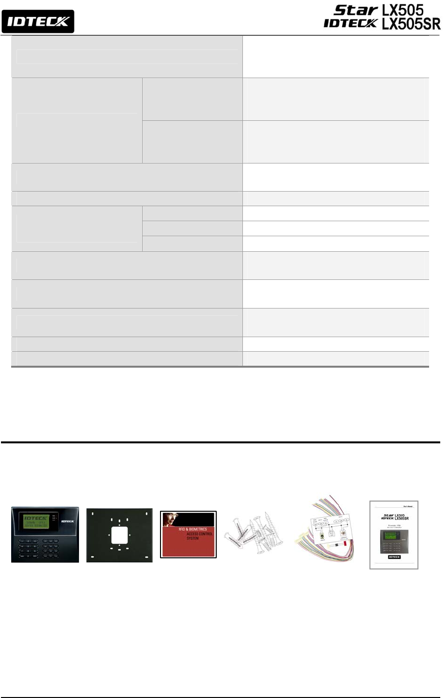
5. Identifying Supplied Parts
Please unpack and check the contents of the box. If any of these parts are missing, please contact a
near-by distributor or IDTECK as soon as possible.
Main Unit Wall Mount CD-ROM Screws
Cable &
Diode&
Resistor
User’s
Manual
(1ea) (1ea) (1ea) (4ea) (4 & 2ea) (1 copy)

9
6. Product Overview
6.1 Features
Standalone Operation
The Star LX505 / IDTECK LX505SR is capable of having an external reader (for 1 Door
Control). This access controller receives card ID numbers and determines whether to allow or
deny access to the door. When an input signal is received, for example from a sensor
activated or an exit button pressed, the controller generates and logs an appropriate response.
All events are stored into the memory buffers. The access controller is a true standalone
device that, in the event of malfunction, will not affect other units when used in conjunction
with one another.
Operation with Host Computer
All event transactions can be managed via the host computer. The data transmitted from the
controller can be displayed and stored on the host PC.
Keypad
If the Star LX505 / IDTECK LX505SR is not connected to a host PC, the built-in keypad and
LCD module can be used for the entire operations and configuration process.
Input / Output
The Star LX505 / IDTECK LX505SR has 4 built-in input ports and 4 output ports (2 relay
outputs and 2 TTL outputs) which can be used to manipulate a wide variety of controls.
Time Schedule Setup
You can program up to 10 time schedules and apply one time schedule to each user. Each time
schedule has 8 different time zones from Monday-Sunday (7 time zones) and one holiday. Each
time zone has 5 different time codes so you can program 5 different time codes for each day.
You can also program time schedules for individual inputs and outputs. That is, if a time
schedule for an input device is activated, that input device will be working only during the
time assigned by that time code. Each time schedule is linked to one holiday schedule.
Holiday Schedule Setup
Excepting Sunday, you can program 100 holidays to one holiday schedule. Each holiday
schedule is linked to one time schedule which has a time code for holidays. You can program
all holidays to a holiday schedule and the time code for holidays is programmed to be the
holiday time zone of time schedule.
Example: A. Holiday schedule 01 linked to time schedule 01,
Holiday schedule 02 linked to time schedule 02
B Holiday schedule 02 linked to time schedule 01,
Holiday schedule 01 linked to time schedule 03

10
Forced Door Open Alarm
When the door is opened by force, the door contact sensor will be activated. For this
application, you have to install the door contact sensor and properly set the door contact time
and outputs to the alarm devices. The Forced Door Open Alarm will be generated until the
alarm is disconnected.
Door Open Timeout Alarm
The Door Open Timeout Alarm will be generated when the door is open for longer than the a
certain time limit, even after the door is opened followed by a normal authentication process.
The Overtime Door Open Alarm will continue to ring until the door is closed.
Anti-pass back
If an additional proximity reader is used, the Anti-pass back mode can be applied. In the Anti-
pass back mode, a user is not allowed to enter or exit when the user violates the one
entry/one exit rule. For example, an identical user won’t be able to enter if he or she
previously exited the door without going through a proper authentication process.
Duress Alarm
In case of duress, enter the 2-digit Duress Password and press the <ENT> key before the
normal access process. The door can be opened as usual, but the duress alarm is also
generated at the same time. The duress alarm output will be sent to the TTL output and an
alarm event will be sent to the host PC.
ARM / DISARM Function for Alarm Panel
While a device is in the ARM condition, its reader ports are all frozen and inputs to the ports
are not processed so that no one can get access to the door. When this mode is applied, the
Star LX505 / IDTECK LX505SR sends signals to other connected security devices so that
they can function accordingly.
Two Men Operation
This feature is to set the Star LX505 / IDTECK LX505SR to allow a certain user (e.g. a visitor)
to pass the door only when that user is accompanied by another special user (e.g. a guider.)
Both of the visitor and the guide should be authorized together for the door to be opened.
4-Level Individual Door Opening Time Setting
This feature is used only for setting four different door opening times.
11
6.2 Product Explanation
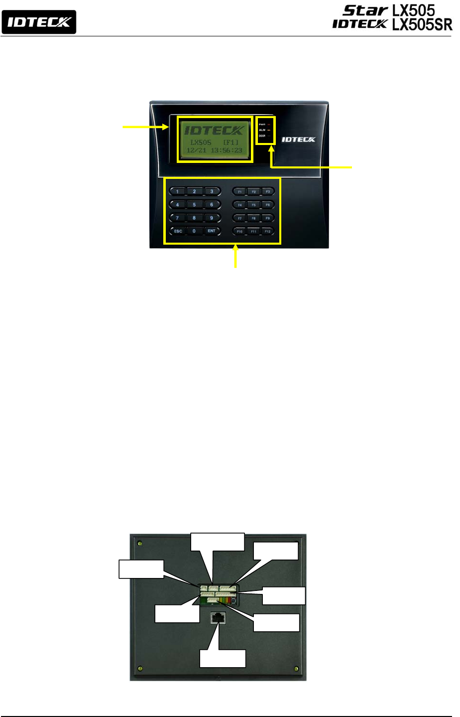
6.2.1 Panel Description
Figure: Description of LX505 Front Panel
•
LCD Module:
The LCD screen displays the status of the LX505.
•
System Operation Status LED:
When the power is applied to the LX505, the red LED is turned on.
When the Relay #1 operates, the green LED is turned on.
When the Relay #2 operates, the yellow LED is turned on.
•
24-key Keypad:
The keypad can be used to manually operate the LX505 with ease.
•
Function Keys:
The LX505 has 12 function keys ([F1] ~ [F12]).
6.2.2 Connection Layout
Figure: Connector Layout
24-key keypad (incl. 12 function keys)
LCD Display
System Operation
Status LED
CNN-2
CNN-1
CNN-6
CNN-3
CNN-4
CNN-5
CNN-7

12
6.2.3 Color Coded & Wring Table
I/O PORT NAME SIGNAL
NAME WIRE COLOR
CNN-1(2PIN CONNECTOR)
Main Power (+12V) DC 12V Red
Power Ground GND 0V Black
CNN-5 (5PIN CONNECTOR)
RS485-RTX(+) RS485-A(+) Yellow wire
RS485-RTX(-) RS485-B(-) Gray wire
RS232-TX TXD Black wire with White stripe
RS232-RX RXD Red wire with White stripe
RS232-GND GND Black
CNN-3 (6PIN CONNECTOR)
TTL OUTPUT #1 TTL#1, WD0 Orange wire with White stripe
TTL OUTPUT #2 TTL#2, WD1 Brown wire with White stripe
Aux Input #1 IN#1 Green
Aux Input #2 IN#2 Green wire with White stripe
Wiegand DATA 0 DATA-0 Pink
Wiegand DATA 1 DATA-1 Cyan
CNN-4 (8PIN CONNECTOR)
Door RELAY(NC) NC(1) Blue wire with White stripe
Door RELAY(COM) COM(1) Gray wire with Red stripe
Door RELAY(NO) NO(1) White wire with Red stripe
Alarm RELAY(NC) NC(2) Purple wire with White stripe
Alarm RELAY(COM) COM(2) White
Alarm RELAY(NO) NO(2) Purple
Exit Button EXIT Orange
Door Sensor CONTACT Yellow wire with Red stripe
CNN-2 (3PIN CONNECTOR)
RS232-RX RXD Pink wire with White stripe
RS232-TX TXD Cyan wire with White stripe
RS232-GND GND Black
CNN-6 (4PIN CONNECTOR)
DP_VCC Orange wire with Red wire
DP_GND Orange wire with Black stripe
DP_D0 DATA-0 Blue
DP_D1 DATA-1 Brown
CNN-7: TCP/IP RJ45 CONNECTOR
13
7. Installation Tips & Check Point
7.1 Check Points before Installation
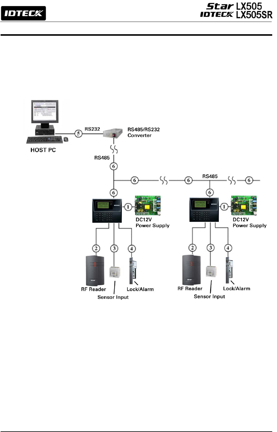
7.1.1 Selection of Cable
The system installation cables should be connected as follows;
Figure: System Installation Layout

14
7.1.2 Recommended Cable Type and Permissible Length
+
: Thicker wires are needed if you connect the reader with high current consumption.
7.2 Check Point during Installation
7.2.1 Termination Resistor
Termination resistors are used to match impedance of the network to the impedance of the
transmission line being used. When impedance is mismatched, the transmitted signal is not
completely absorbed by the receiver and a portion of signal is reflected back into the
transmission line. The decision whether or not to use termination resistors should be based on
the cable length and data rate used by the communication system.
For example, if you use 9,600 baud rate and 1,200m length of cable, the propagation velocity of
cable is 0.66 x speed of light (This value is specified by the cable manufacturer), if we assume the
reflections will damp out in three round trip up and down the cable length, the transmitted signal
will stabilize 18.6us after the leading edge of a bit. Since the data bit is captured in the middle of
the bit which is approximately 52us after the leading edge of a bit. The reflection stabilizing time
18.6us is much before the center of the bit therefore the termination resistors are not required.
However, if you install the cable to maximum length, the impedance of cable and network is
mismatched and the transmitted signal is overlapped by the reflected signal. In this case, it is
recommended to add termination resistors to the end of the receiver lines. A 120Ω resistor can
Reference Description Cable
Specification
Maximum
Distance
1 LX505 Power (DC12V)
DC Power -> LX505
Belden #9409,
18 AWG
2 conductor, unshielded
30m
Belden #9512,
22 AWG
4 conductor, shielded
2
Reader
(Power and Data)
Exit Reader -> RF20 Belden #9514,
22 AWG
8 conductor, shielded
150m
Belden #9512,
22 AWG
4 conductor, shielded
3
Door Contact
Exit Button
Sensor Input
Input -> LX505
Belden #9514,
22 AWG
8 conductor, shielded
300m
4 Door Lock, Alarm Device
Lock (Alarm) -> LX505
Belden #9409,
18AWG
2 conductor, unshielded
300m
5 RS232 Cable
Converter -> Host P.C.
Belden #9829,
24 AWG
2-twisted pair, shielded
15m
6
RS485 Cable
LX505 -> LX505
LX505 -> Converter
Belden #9829,
24 AWG
2-twisted pair, shielded
1,200m
15
be used for termination resistor in parallel between the receiver lines “A” and “B” for 2 wires
RS485 system. A termination resistor of less than 90Ω should not be used and no more than 2
terminations should be used in one network system.
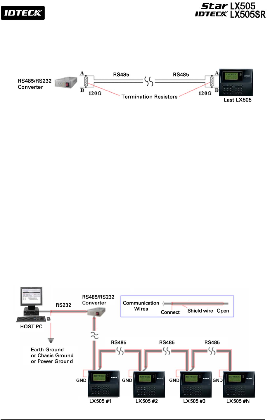
7.2.2 How to Connect Termination Resistors
Figure: Termination resistors for 2 wire RS485 communication system
7.2.3 Grounding System for Communication Cable
We recommend you to use a proper grounding system for the communication cables. The best
grounding method is to put the shield wire of the communication cable to the 1st class earth
grounding; however bringing the earth ground to the communication cable isn’t easy and the
installation cost increases. There are three grounding points you can find during installation;
1. Earth Ground 2. Chassis Ground 3. Power Ground
The most important point about grounding system is not to connect both ends of shield wires to
the grounding system; in this case, there will be a current flow through the shield wire when
the voltage level of both ends of shield wire is not equal and this current flow will introduce
some noise and interference to communications. For better grounding, we advise you connect
ONLY one end of shield wire of communication cable to the grounding system; If you find earth
ground nearby, then connect one end of the shield wire to the earth ground; If you do not have
earth ground nearby, then find chassis ground and connect one end of shield wire to chassis
ground; If you do not find either earth ground or chassis ground, then connect one end of shield
wire to power ground. (GND of LX505) Note that if the chassis ground is not properly connected
to the earth and floated from the ground level, then grounding to the chassis ground will give
the worst communication. Therefore, we recommend to using power ground instead of chassis
ground if that is the case.
Figure: Grounding system
16
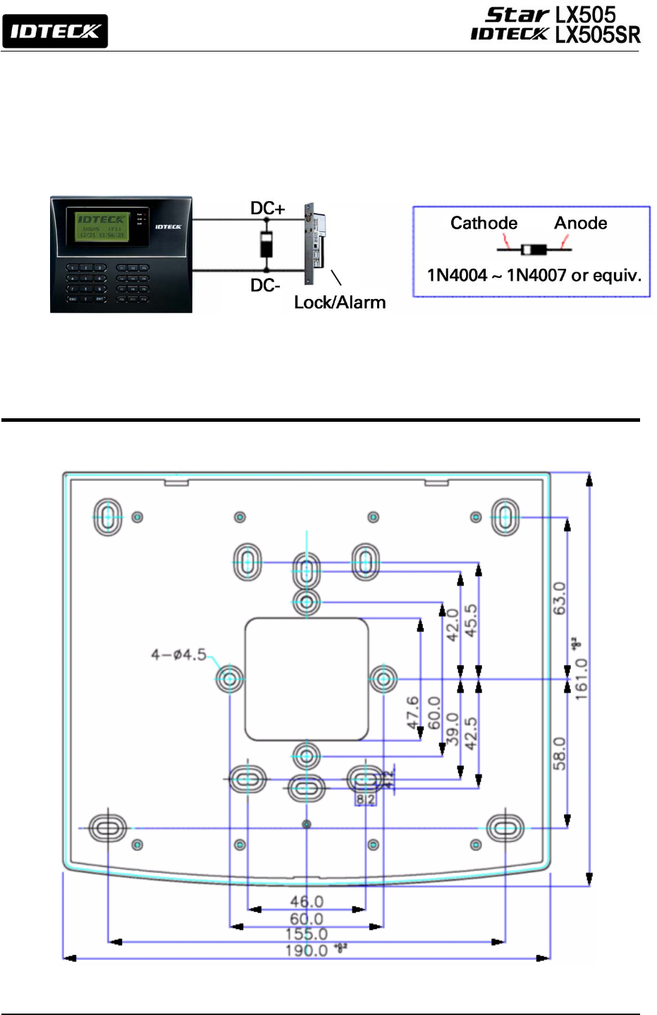
7.2.4 Reverse Diode Connection
If you connect an inductor (Door Locks or Alarm device) to the output relays, there will be a
high surge voltage created while the inductor is turning on and off. If you do not connect a
reverse diode, the surge voltage will transfer and damage the electronic circuit of the controller.
It is strongly recommended to add a reverse diode between the inductor coils to absorb this
surge voltage.
Figure: Reverse Diode connection
8. Installation of the Product
8.1 Wall Mount (Unit: mm)
Figure: Wall Mount Layout
17
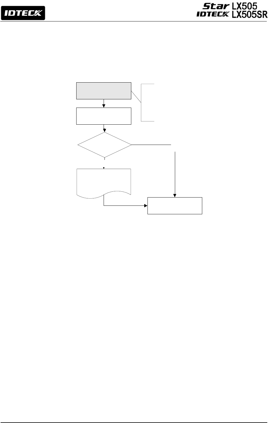
<1> KEY?
“SYSTEM
INITIALIZED!!!”
Power ON
Initialize OK?
1: Yes 0: No
Normal Operation
Yes
No
Press and hold the
initialization button. Put the
+12V DC power to the LX007.
Release the button when the
LCD displays “Initialize OK?”
8.2 System Initialization (External Reader Port)
After the installation and connections are completed, apply power (DC12V) to LX505 with the
initialization button being held down. Then, the LCD will first display “Initialize OK? 0:No
1:Yes”. Press <1> key if you want to initialize the system. After all the initialization process is
completed, the system will be operating on the normal mode and the LCD will display
“IDTECK, LX505 [F1], Date Time”.
8.3 Wall Mount Installation
1. Position the Wall Mount to the location at which you want to install the unit and mark 4 x
drilling positions. Drill 6-32 holes for at least 4 mounting points.
2. Drill a 1/2” hole on the center of the Wall Mount.
3. Using 4 screws, install the Wall Mount to the proper location.
4. Take out the cable through the center hole.
5. After the wiring is done as explained in the next section, put the Main Unit on the Wall
Mount and screw it.
8.4 Wiring
8.4.1 Power Connection
1. Connect (+) wire of DC 12V Power Supply to Red wire.
2. Connect GND (-) wire of DC 12V Power Supply to Black wire.
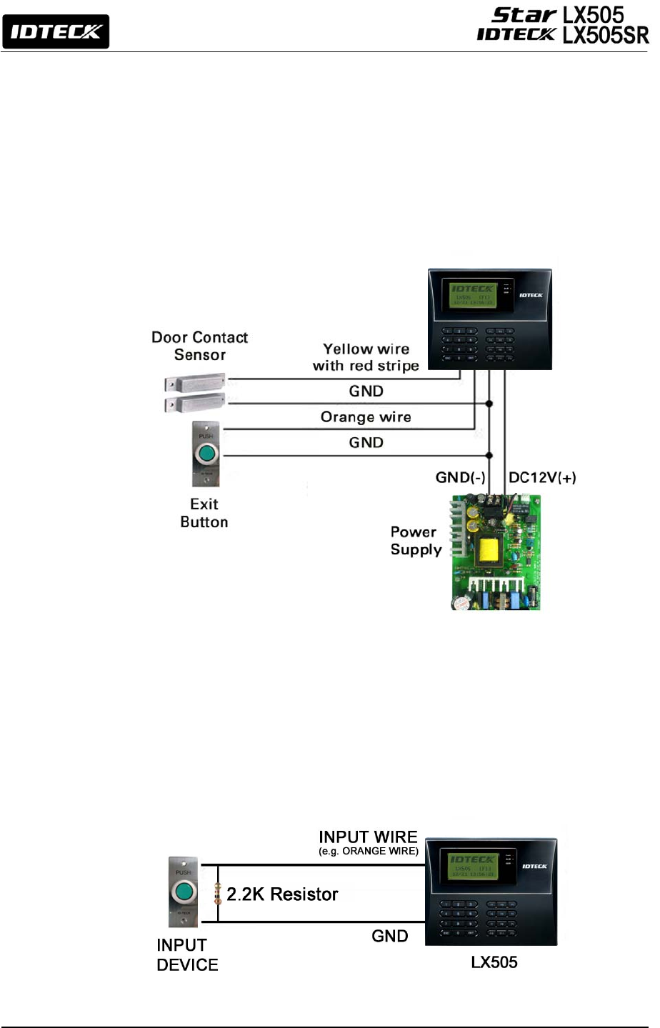
8.4.2 Input Connection
Exit Button Connection
1. Connect one wire from Exit Button to Orange wire.
2. Connect the other wire from Exit Button to the GND.
18
Door Contact Sensor Connection
1. Connect one wire from Door Contact Sensor to Yellow wire with Red stripe.
2. Connect the other wire from Door Contact Sensor to GND.
Auxiliary Input Connection
(Applicable to Aux Input #1(Green wire), Aux Input #2(Green wire with white stripe))
1. Connect one wire from Auxiliary Input Device to one of Aux Input #1 or Aux Input #2.
2. Connect the other wire from Auxiliary Input Device to GND.
Figure: Input Device Connection
2.2K Resistor Connection for Cut Off Check
You have to connect a 10K resistor between the input wire (e.g. Orange wire) and the
GND to apply the Cut Off Check feature. First, select whether or not to check the cutoff
status of each device from [F5 SETUP MENU] -> Cut Off Check. Second, configure the
desired output that you want to be generated in the event of a cutoff from [F5 SETUP
MENU] -> Cut Off Alarm.
Figure: 2.2K Resistor Connection for Cut Off Check
19
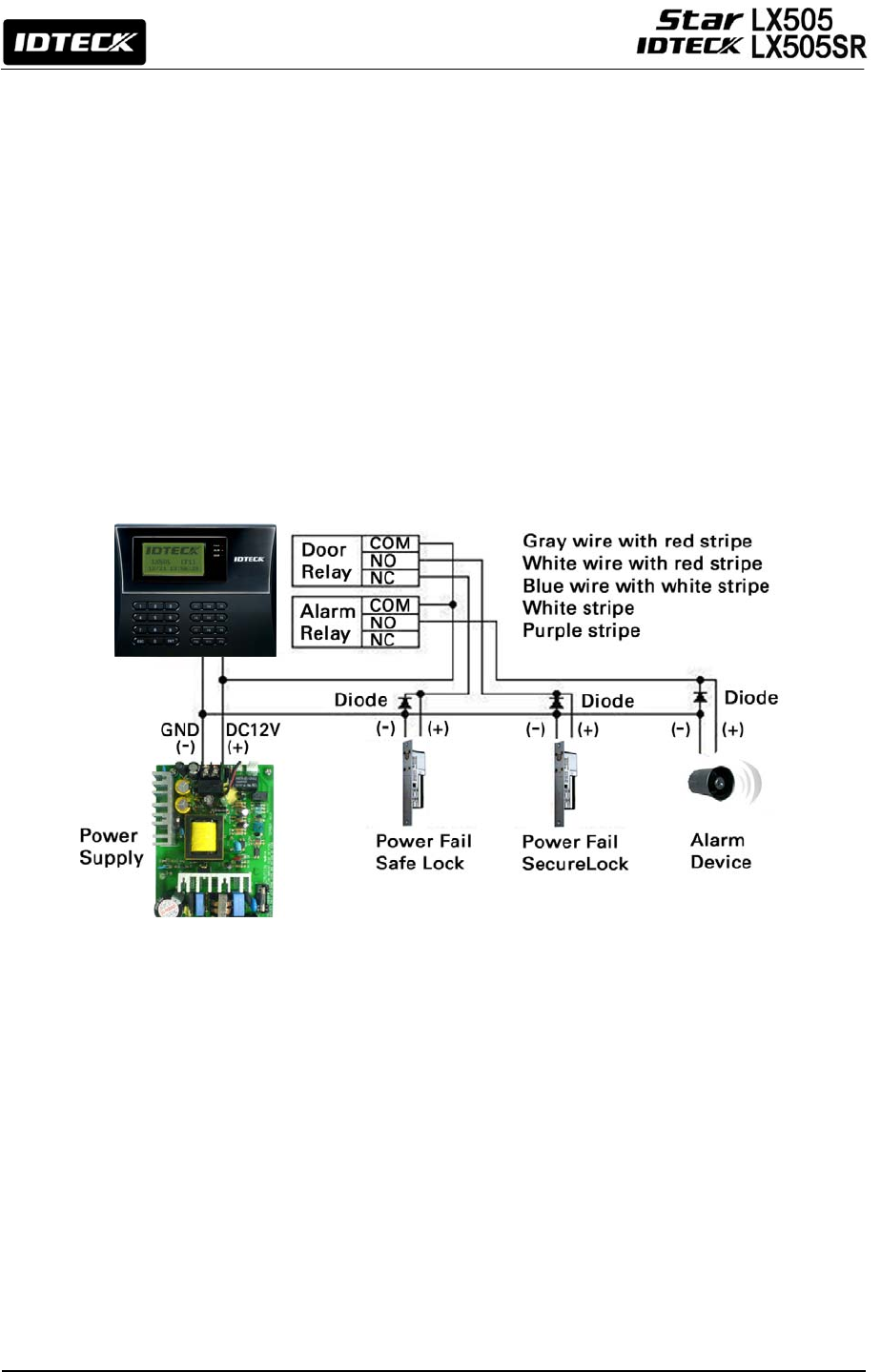
8.4.3 Output Connection
Door Lock (Power Fail Safe) Connection (Door Relay)
1. Connect COM wire of Door Relay, White wire with red stripe to +12V.
2. Connect NC wire of Door Relay, Blue wire with white stripe to (+) wire of Door Lock.
3. Connect GND wire to (-) wire of Door Lock.
Door Lock (Power Fail Secure) Connection (Door Relay)
1. Connect COM wire of Door Relay, Gray wire with Red stripe to +12V.
2. Connect NO wire of Door Relay, White wire with Red stripe to (+) wire of Door Lock.
3. Connect GND wire to (-) wire of Door Lock.
Alarm Device Connection (Alarm Relay)
1. Connect COM wire of Alarm Relay and White wire to +12V.
2. Connect NO wire of Alarm Relay, Purple wire to (+) wire of Alarm device.
3. Connect GND port to (-) wire of Alarm device.
Figure: Door Lock, Alarm Device Connection
CAUTION: You should connect REVERSE DIODES as shown in the
picture above. A desirable DIODE is a Fast Recovery DIODE
(current=min. 1A), 1N4004 - 1N4505 or similar.
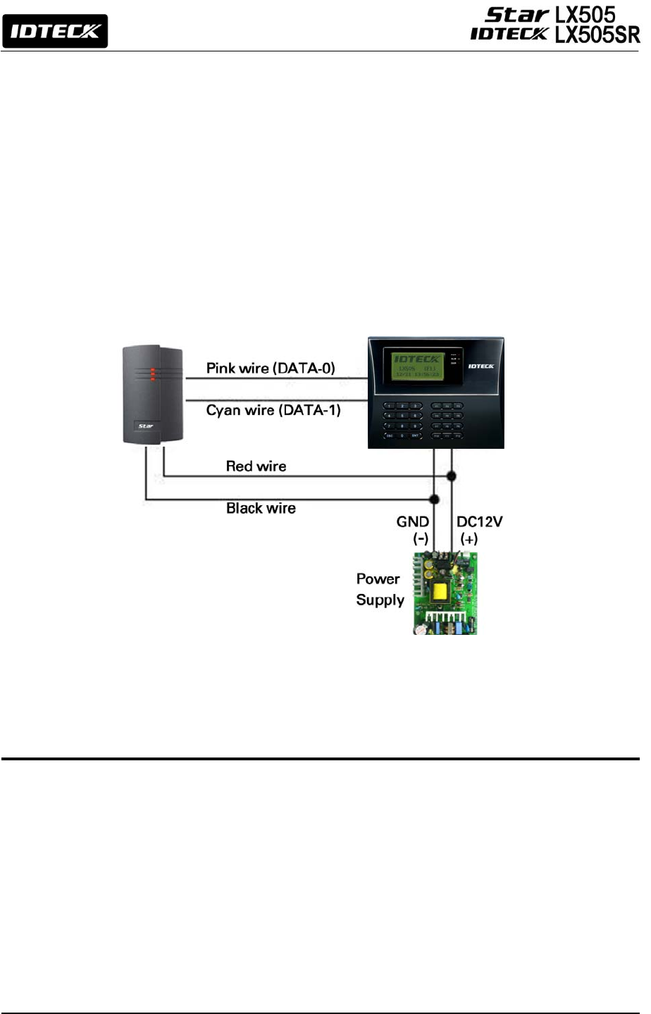
8.4.4 External Reader Connection
Proximity Reader Connection
1. Connect (+) wire of the Proximity Reader to DC +12V.
2. Connect (-) wire of the Proximity Reader to GND.
3. Connect Data-0 wire of the Proximity Reader to Pink wire.
4. Connect Data-1 wire of the Proximity Reader to Cyan wire.
20
•
Compatible Readers (External Reader):
Star LX505:
Standard 26bit Wiegand Format Proximity Readers
Standard 26bit Wiegand + 8bit Burst Format Proximity and keypad Reader
IDTECK LX505SR:
Standard 34bit Wiegand Format Proximity Reader
Standard 34bit Wiegand + 8bit Burst Format Proximity and keypad Reader
•
Recommended Readers
Star LX505: RF TINY, RF10/20/30/70/500, RFK101, FGR006, FGR006EX
iPASS IP-LX505: IP10/20/30, IPK101
IDTECK LX505SR: SR10/20/30, SRK101, FGR006SRB
Figure: External Reader Connection
9. Communication
9.1 RS232 Communication Port Connection
A 9-pin connector (Serial communication connector, female) is required to connect the LX505
with a host computer via RS232 communication.
Please follow the steps below.
1. Connect RS232-TX, Black wire with white stripe to the pin #2 (RXD) of the 9-pin connector.
2. Connect RS232-RX, Red wire with white stripe to the pin #3 (TX) of the 9-pin connector.
3. Connect GND, Black wire to the pin #5 of the 9-pin connector.
4. Plug in the 9-pin female connector to COM1 or COM2 Port of the host PC.
5. Install and run the LX505 Application Software.
21
Figure: RS232 COMMUNICATON
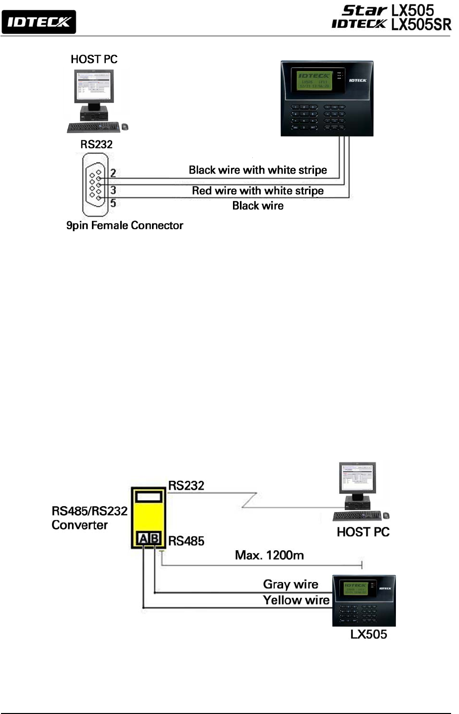
9.2 RS485 Communication Port Connection
9.2.1 RS485 Connection (Standalone Unit)
An RS485/RS232 converter is required to use the RS485 communication between the
LX505 and a host PC. Please follow the steps below.
1. Connect RS485-RTX (+), Yellow wire to RS485-A port of the converter.
2. Connect RS485-RTX (-), Gray wire to RS485-B port of the converter.
3. Plug the RS232, 9-pin connector of the converter into the COM1 or COM2 port of the
host PC.
4. Install and run the LX505 Application Software.
Figure: RS485 Connection between LX505 units and a host PC
22
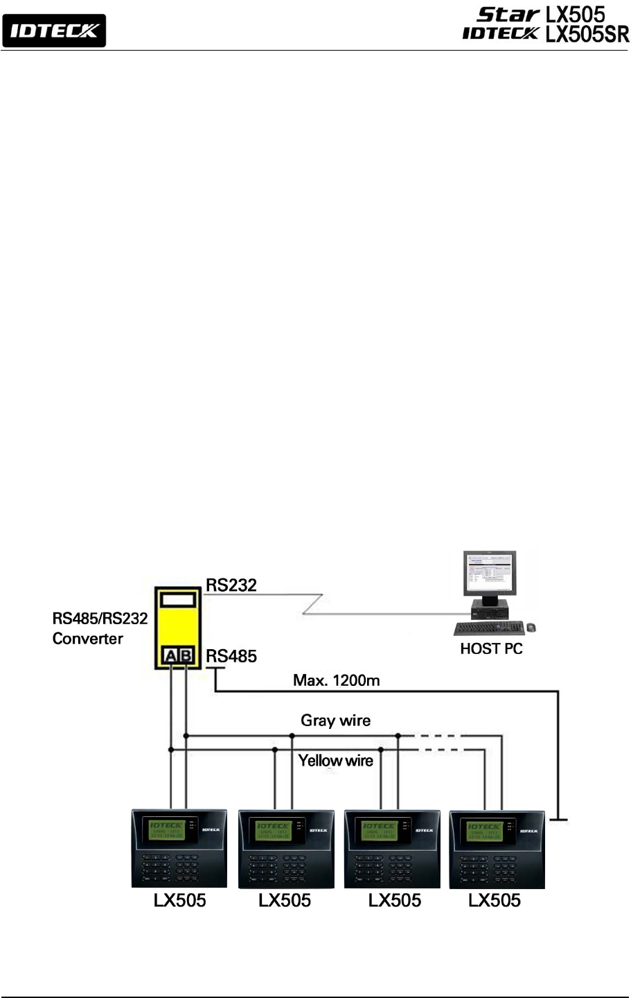
9.2.2 RS485 Connection (Multiple Units)
An RS485/RS232 converter is required to use RS485 communication between multiple
LX505 and a host PC. Please follow the instructions below.
First, connect all RS485 port of the LX505 units in parallel.
(max of 32 LX505 Units can be connected)
1. Connect RS485-RTX (+) (the Yellow wire) of one LX505 to RS485-RTX (+) (the
Yellow wire) of another LX505.
2. Connect RS485-RTX (-) (the Gray wire) of one LX505 to RS485-RTX (-) (the Gray
wire) of another LX505.
3. Set different COMM IDs for each LX505.
Second, connect one of RS485 ports of the LX505 units to the
RS485/RS232 converter.
1. Connect RS485-RTX (+) (the Yellow wire) of one LX505 to RS485-A port of the
converter.
2. Connect RS485-RTX (-) (the Gray wire) of one LX505 to RS485-B port of the
converter.
3. Plug the RS232 (9-pin connector) of the converter into the COM1 or COM2 port of
the host PC.
4. Install and run the LX505 application software.
Figure: RS485 Communication between multiple LX505 units and a host PC
23
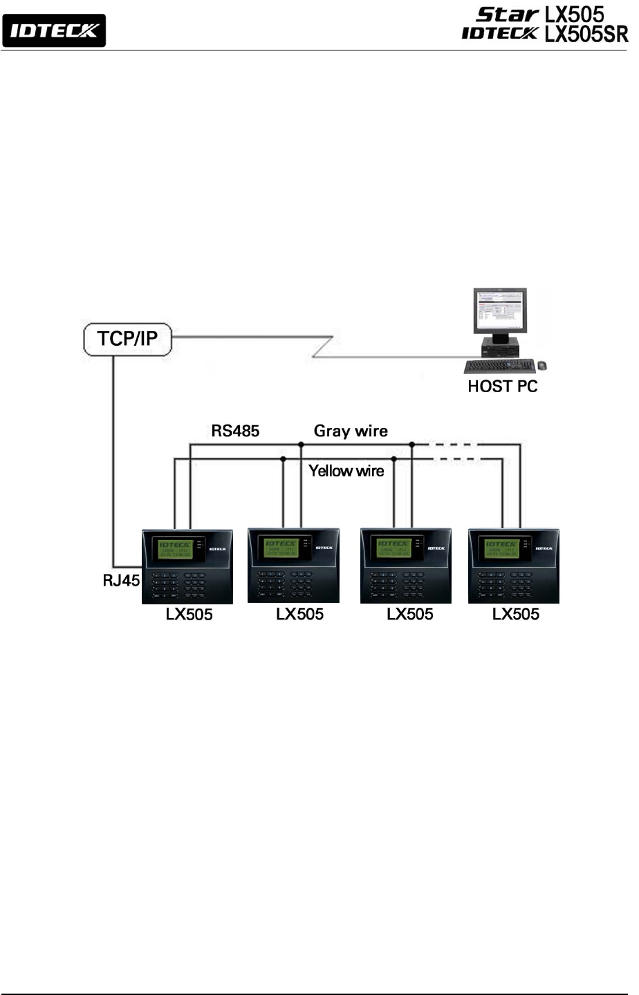
9.3 TCP/IP Communication Port Connection (Optional)
An optional TCP/IP Module is required for TCP/IP communication to the host PC. Follow the next
instruction.
1. Connect RJ45 plug, LAN cable of the network system to RJ45 jack of the LX505.
2. If you install multiple LX505s and only one TCP/IP port is available, you may connect one
LX505 to TCP/IP and then connect all the LX505s using the RS485 multiple communication
as shown in the below figure.
3. Set different COMM IDs for each LX505.
4. Install and run the LX505 Application Software.
Figure: TCP/IP Communication between multiple LX505 units and a host PC
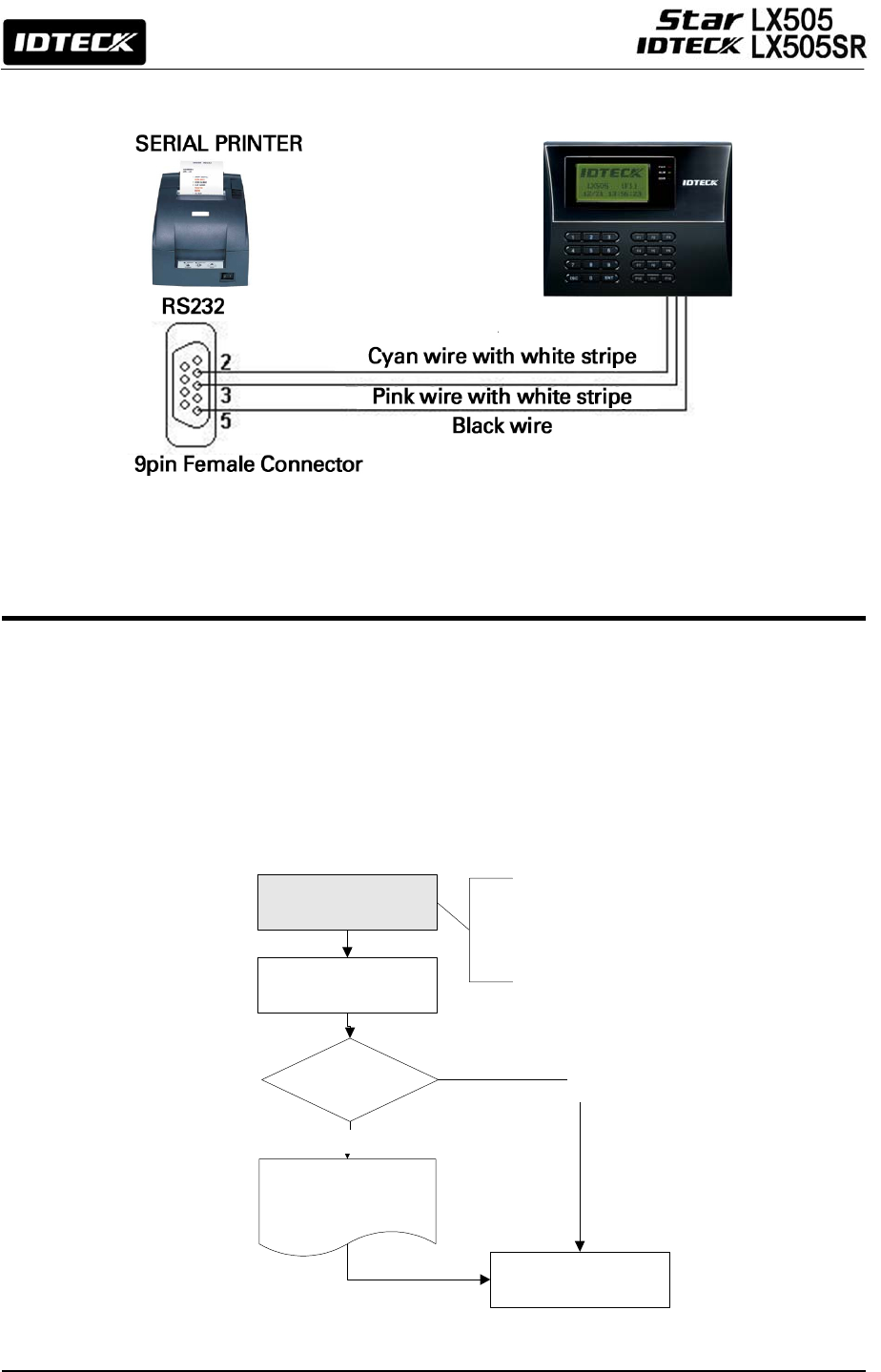
9.4 Serial Printer Connection
A 9-pin connector (Serial communication connector, female) is required to connect the LX505
with a serial printer via RS232 communication. Please follow the steps below.
1. Connect RS232-TX, Cyan wire with white stripe to the pin #2 (RXD) of the 9-pin connector.
2. Connect RS232-RX, Pink wire with white stripe to the pin #3 (TX) of the 9-pin connector.
3. Connect GND, Black wire to the pin #5 of the 9-pin connector.
4. Plug in the 9-pin female connector to COM1 or COM2 Port of the serial printer.
5. Set the Print Output setting to ‘Auto Print’ or ‘Manual Print’ from [F3 SETUP MENU].
24
<1> KEY?
“SYSTEM
INITIALIZED!!!”
Power ON
Initialize OK?
1: Yes 0: No
Normal Operation
Yes
No
Press and hold the
initialization button. Put the
+12V DC power to the LX505.
Release the button when the
LCD displays “Initialize OK?”
Figure: RS232 Communication between the LX505 and a Serial Printer
10. Basic Setting
10.1 Initialization of LX505
After the installation and connections are completed, supply power (+12V DC) to LX505 with
the initialization button being held down. Then, the LCD will first display “Initialize OK? 0:No
1:Yes”. Press <1> key if you want to initialize the system. After all the initialization process is
completed, the system will be operating on the normal mode and the LCD will display
“IDTECK, LX505 [F1], Date Time”.
25
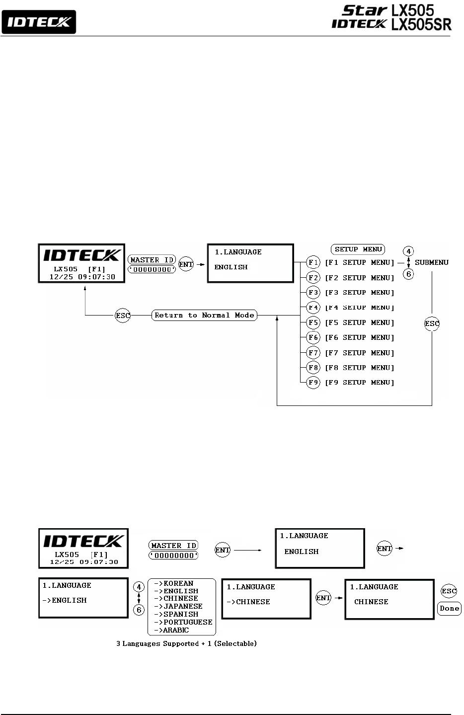
10.2 How to Enter the SETUP MENU
To set up the LX505 or to change the settings, you have to enter the SETUP MENU first. To do
so, press <0> key eight (or ten) times and <ENT> key on the keypad. (The Default Master ID
is ‘00000000’. For LX505SR, it’s ‘0000000000’.)
There are 9 SETUP MENUS and you automatically [F1 SETUP MENU] first. You can move to
other SETUP MENUS by pressing <F1> to <F9> keys. For example, if you want to go to [F2
SETUP MENU] then press <F2> key, to enter [F5 SETUP MENU], press <F5> key and so on
and on. There are several SUBMENUS inside each SETUP MENU and you can scroll up and
down the SUBMENU by pressing <4> and <6> key. If you don’t press any key within 60
seconds or if you press <ESC> key, the LX505 will exit the SETUP MENU and return to the
normal operating mode. You can change the Master ID in the [F7 SETUP MENU].
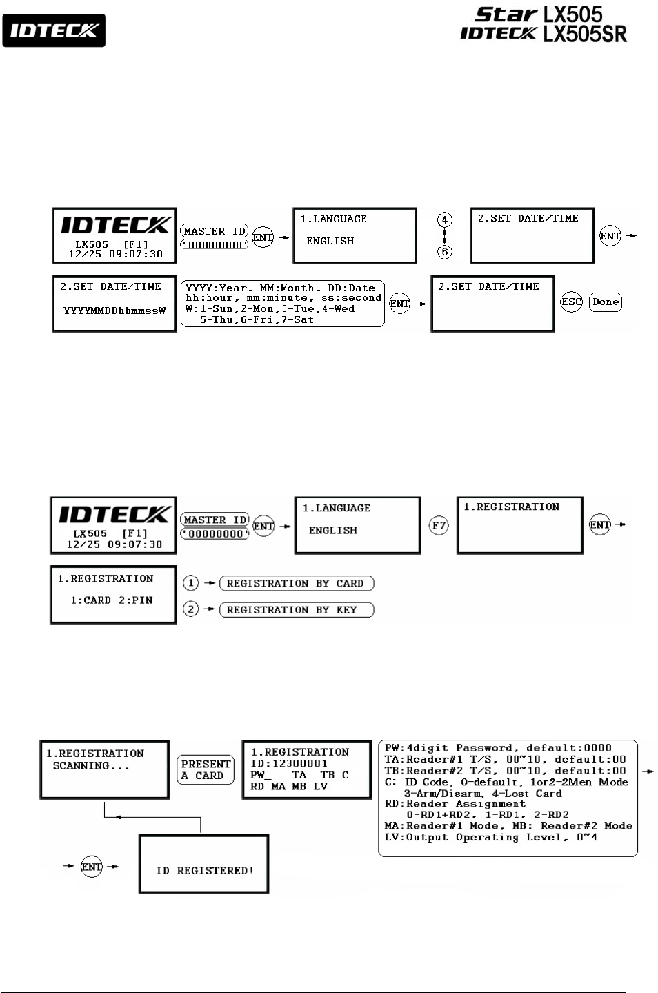
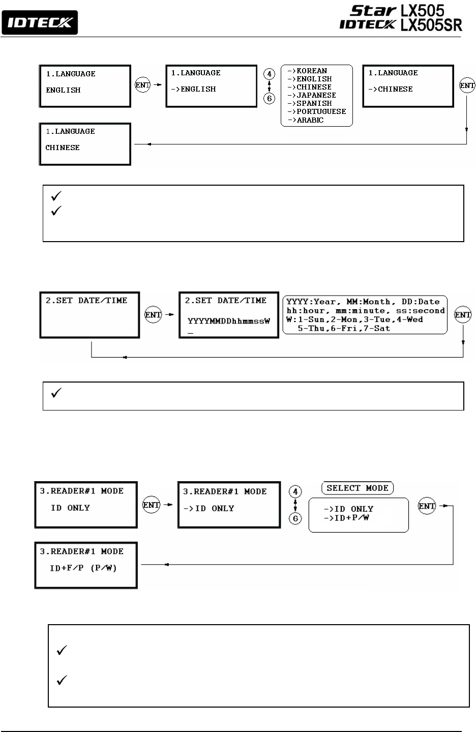
10.3 Language Setting
Select [LANGUAGE] in the [F1 SETUP MENU] then press <ENT> key to select which
LANGUAGE to use. The steps below show how to choose CHINESE, for example.
26
10.4 DATE / TIME SETTING
Select [SET DATE/TIME] in the [F1 SETUP MENU] and enter the total of 15 digits (i.e. Year /
Month / Date / Hour / Minute / Second / Day) as shown below. The LCD will display the new
Date and Time after the time setting is completed but the year and day will not be displayed.
The LX505 has a 24 hours system. The day codes are 1 for Sunday, 2 for Monday, 3 for
Tuesday, 4 for Wednesday, 5 for Thursday, 6 for Friday and 7 for Saturday.
10.5 ID REGISTRATION
To register a User ID to the LX505, select [F7 SETUP MENU] -> [REGISTRATION]. You can
choose to register an ID a) using the card or b) by entering the PIN.
a) Registration by Card

27
b) Registration Using Keypad
NOTE| In case you make a typing mistake during the registration process, you can press F1
button to erase your errors.
1. Scanning – means the reader is waiting for an ID number to be entered. The card number
for the card will appear with a beep sound when you present the card.
2. ID – is a Personal Identification Number (PIN) that consists of 4-8 digits. Enter a 4-8digit ID
number (PIN) and press <ENT> key. (For LX505SR, the ID number consists of 4-10 digits.
3. PW – stands for a password that is required for verification in the RF + Password operating
mode.
4. TA – refers to the Time Schedule code (‘00’ ~ ‘10’) for the Reader#1 (i.e. the built-in
reader). Cardholders are granted access only during the Time Intervals of the Time
Schedule code entered to this TA field. To set the Time Intervals for each Time Schedule
code, refer to the instructions on the Time Schedule Setup in the [F4 SETUP MENU]. If
you want allow the cardholder access to the door anytime, then enter the default Time
Schedule code '00' for the value.
5. TB – refers to the Time Schedule code (‘00’ ~ ‘10’) for the Reader#2 (i.e. Exit Reader).
Cardholders are granted access only during the Time Intervals of the Time Schedule code
entered to this TB field. To set the Time Intervals for each Time Schedule code, refer to the
instructions on the Time Schedule Setup in the [F4 SETUP MENU]. If you want allow the
cardholder access to the door anytime, then enter the default Time Schedule code '00' for
the value.
6. RD – refers to the Reader Assignment code for the cardholder. Entering the code ‘0’
assigns both readers (Built-in Reader and Exit Reader) to grant access to the user that is
being registered, code ‘1’ only assigns Reader#1 (Built-in Reader) and code ‘2’ assigns
Reader#2 (Exit Reader). If you enter ‘1’ in the RD field(Only Reader#1 assigned) and try to
exit through Reader#2 (Exit Reader) then LX505 generates an error message (“Access Door
Error”) on the LCD display.

28
7. C – stands for the ID code. Code ‘0’ is default and code ‘1’ or ‘2’ is a code used for the
TWO MEN MODE. Code ‘3’ is used for the ARM/DISARM function and code ‘4’ is assigned
for lost cards.
8. MA – refers to the Operating Mode of the Reader#1 (i.e. the built-in reader) for the
cardholder. If you enter ‘1’ for MA, for example, Reader#1 will be operating always on RF
Only Mode.
• ‘0’ – System Operating Mode (Path: [F1 SETUP MENU] > [READER#1 MODE])
• ‘1’ – ID Only Mode
• ‘2’ – ID + Password Mode
9. MB – refers to the Operating Mode of the Reader#2 (Exit Reader) for the cardholder. If you
enter ‘1’ for MB, for example, Reader#2 will be operating always on RF Only Mode.
• ‘0’ – System Operating Mode (Path: [F1 SETUP MENU] > [READER#1 MODE])
• ‘1’ – ID Only Mode
• ‘2’ – ID + Password Mode
10. LV – refers to the Output Operating Level for the cardholder. Output operating time can be
set for each user. To configure an Output operating time for each level, refer to the
instructions on Output Setting in the [F6 SETUP MENU].
• ‘0’ or ‘1’ – Level #1
• ‘2’ – Level #2
• ‘3’ – Level #3
• ‘4’ – Level #4

29
11. OPERATIONS
11.1 Normal Operation
Power on
When power is applied to the LX505, the Red LED is lit.
Registered card reading
When a registered card (or a PIN) is read (and his/her password is verified), the Door
(Relay#1) will open for 3 seconds (Default) with the Green LED on.
Exit Button
When the Exit button is pressed, the Door (Relay#1) will open for 3 seconds with the
Green LED on.
Alarms
When an unregistered card is read or his/her password is not verified, the access is
denied and the Alarm (Relay#2) will be activated for 3 seconds with the Yellow LED on.
11.2 Default Setting
When you operate the system for the first time or the system has been initialized, the factory
setting values (i.e. the default settings) will be stored in the memory. You can change the
settings for the desired application.
30
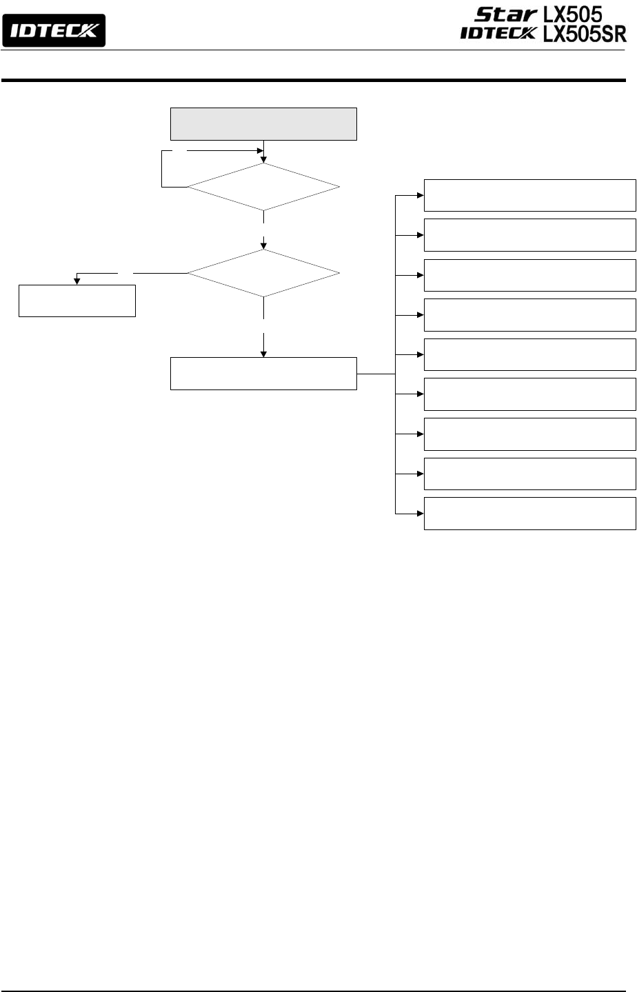
12. Setting Changes
To set up the LX505 or to change the settings, you have to enter the SETUP MENU first. To do
so, press <0> key eight (or ten) times and <ENT> key on the keypad. (The Default Master ID
is ‘00000000’. For LX505SR, it’s ‘0000000000’.)
There are 9 SETUP MENUS and you automatically enter [F1 SETUP MENU] first. You can
move to other SETUP MENUS by pressing <F1> to <F9> keys. For example, if you want to go
to [F2 SETUP MENU] then press <F2> key, to enter [F5 SETUP MENU], press <F5> key and
so on and on. There are several SUBMENUS inside each SETUP MENU and you can scroll
up and down the SUBMENU by pressing <4> and <6> key. If you don’t press any key within
60 seconds or if you press <ESC> key, LX505 will exit the SETUP MENU and return to the
normal operating mode. You can change the Master ID in the [F7 SETUP MENU].
INITIAL DISPLAY
(MODEL NAME, CURRENT TIME)
ID INPUT?
MASTER ID
/PW/FINGERPRINT ?
YES
YES
NO
NORMAL OPERATIONS
MODE
SETUP MODE
NO
F1 SETUP MENU
F2 SETUP MENU
F3 SETUP MENU
F4 SETUP MENU
F5 SETUP MENU
F6 SETUP MENU
F7 SETUP MENU
F8 SETUP MENU
F9 SETUP MENU
31
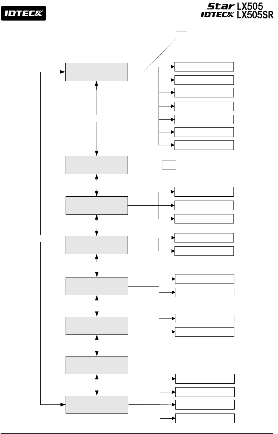
12.1 F1 SETUP MENU
LANGUAGE
SET DATE/TIME
READER#1 MODE
KOREAN
<4> or <6> KEY
<4> or <6> KEY
<4> or <6> KEY
<4> or <6> KEY
READER#2 MODE
RD1 PIN INPUT
RD2 PIN INPUT
<4> or <6> KEY
<4> or <6> KEY
<4> or <6> KEY
COMM ADDR SET
<4> or <6> KEY
BAUD RATE
ENGLISH
CHINESE
JAPANESE
SPANISH
PORTUGUESE
Enter 15 digits for date and time
ID ONLY(DEFAULT)
ID+F/P (P/W)
ID+P/W+F/P
ID ONLY
ID+P/W
NOT USE(DEFAULT)
USE
NOT USE(DEFAULT)
USE
9600
19200(RECOMMENDED)
38400
57600
ARABIC
3 Languages Supported
+ 1 Selectable
32
12.1.1 Language
12.1.2 Date and Time Setting
12.1.3 Reader #1 Mode
The default language is English.
Supported languages include English, Spanish, Portuguese and one of Chinese, Korean,
Japanese and Arabic (selectable).
e.g. 200302101330152 = Feb. 10, 2003, 13:30:15, Monday
Note: READER#1 is the built-in proximity reader in the unit.
ID(PIN) ONLY: In this mode, users can access the door by simply presenting their card
or entering their ID number.
ID+ P/W: In this mode, users can access the door by presenting their card or entering
their ID number and then verifying their identity by a password.
33
12.1.4 Reader #2 Mode
The READER#2 MODE setting menu is the same as READER#1 MODE setting menu in
the previous section.
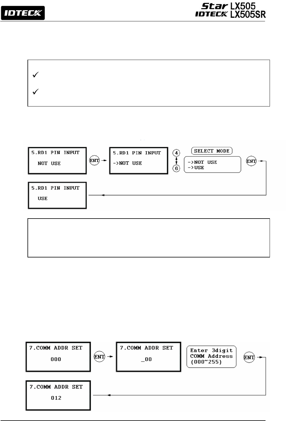
12.1.5 Reader #1 PIN Input
12.1.6 Reader #2 PIN Input
READER#2 PIN INPUT setting can be configured in the same way as READER#1 PIN
INPUT setting in the previous entry
12.1.7 Communication Address Setting
This setting allows you to decide whether to USE or NOT USE the keypad inputs for the
Reader#1.The default setting is NOT USE the keypad inputs. If you want to access the door
by entering the user ID by keypad, set this mode USE.
Note: Set this mode to USE when you use the password verification method.
Note: READER#1 is
t
he Exit Reader connected to the LX505.
ID ONLY: In this mode, users can exit/enter the door by simply presenting their card or
entering their ID number.
ID+P/W: In this mode, users can exit/enter the door by presenting their card or entering
their ID number and then verif
y
in
g
their identit
y
throu
g
h a
p
assword.
34
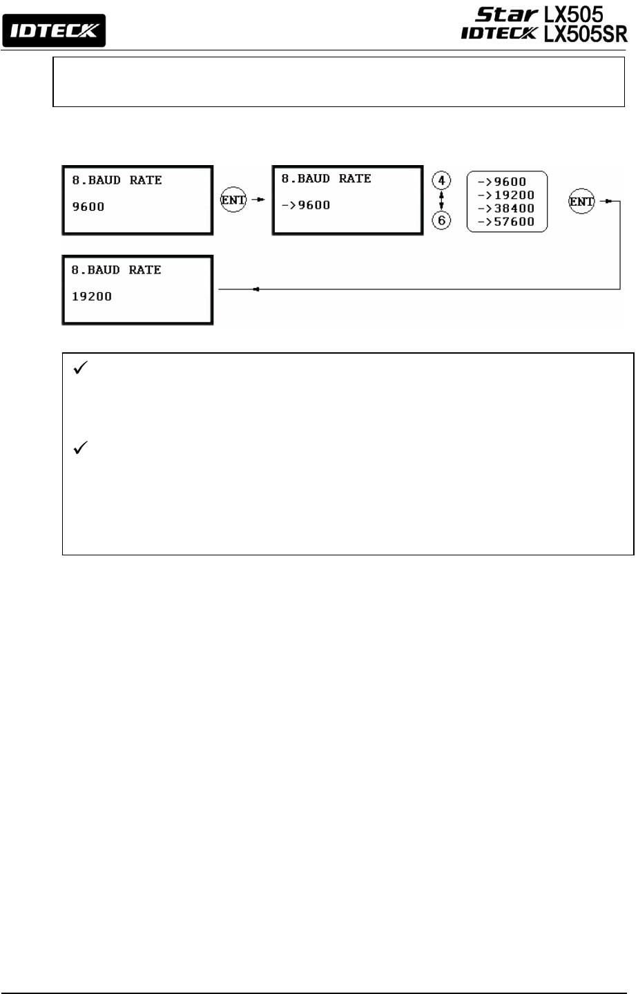
12.1.8 Baud Rate Setting
The LX505 supports different Baud Rates of 9600, 19200, 38400 and 57600bps. The
recommended Baud Rate is 19200bps. An incorrect Baud Rate setting will result in
communication errors. Note that you should always set the same Baud Rate for the
same communication network.
If you have a communication problem, please check the followings;
- Check the Communication Address for both the LX505 and the host PC in the Software.
- Check the Baud Rate setting of both the LX505 and the host PC software.
- Check the COM port and the cable.
- Check the COM port settings of the host PC
(Parity Bit: None, Data Bit: 8 bits, Stop Bit: 1 bit)
The default Communication Address is “000”
Set different communication addresses for each unit in the loo
p
.
35
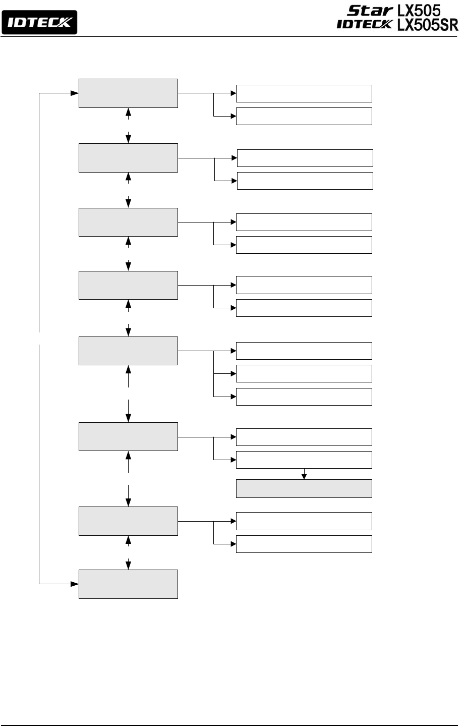
12.2 F2 SETUP MENU
APB MODE
DURESS MODE
WIEGAND OUTPUT
<4> or <6> KEY
<4> or <6> KEY
<4> or <6> KEY
<4> or <6> KEY
OPEN ALR TIME
EVENT MEMORY
ID DISPLAY
TIME UNIT
<4> or <6> KEY
<4> or <6> KEY
<4> or <6> KEY
OUTPUT T/S+ID
<4> or <6> KEY
NOT USE
USE(DEFAULT)
MESSAGE(DEFAULT)
ID+MESSAGE
UNIT: 1 SEC (DEFAULT)
UNIT: 0.1 SEC
NOT USE(DEFAULT)
USE
NOT USE(DEFAULT)
USE
NOT USE(DEFAULT)
USE
NOT USE(DEFAULT)
USE
ALL FLAG RESET
DURESS P/W SETTING
36
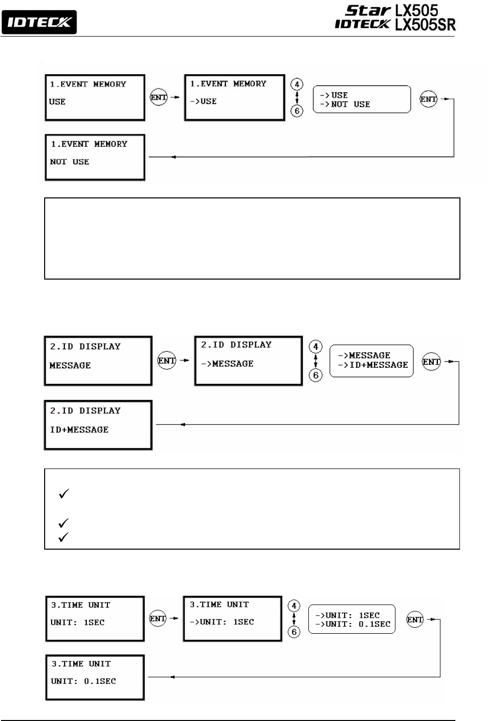
12.2.1 Event Memory
12.2.2 ID Display
12.2.3 Time Unit Setting
You can select whether to activate the event memory or not. If you set the event memory to
USE, the LX505 generates an error message and keeps all event transactions stored in the
memory. If you select NOT USE, however, the LX505 will not generate an error message
and new events will be overwritten into the event buffers. If you use the LX505 in a stand
alone configuration (just for door access), select NOT USE.
If you want to display user ID numbers on the LCD, select ID+MESSAGE.
MESSAGE: A text message and asterisks “********” will appear and the user ID
number won’t be displayed.
ID+MESSAGE: The user ID number will be displayed on the LCD with a text message.
The default setting is ‘MESSAGE’.
37
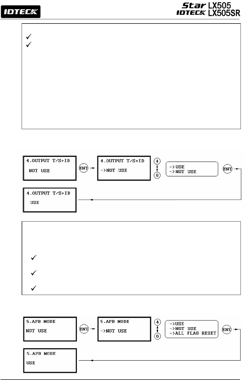
12.2.4 Output T/S + ID
12.2.5 Anti-pass-back Mode
This setting allows you to define the unit of time.
1sec: Output Time is calculated in the time unit of 1 second for the IN/OUT definition.
0.1sec: Output Time is calculated in the time unit of 1/10 second (or 100ms) for the
IN/OUT definition
e.g. If you want to activate the Door Relay (Relay #1, DR) for 3 seconds, appropriate
setting values are as follows;
- The Time Unit should be set to 1 SEC.
- The Door Relay (DR) Output Time should be set to “03”.
e.g. If you want to activate Door Relay (Relay #1, DR) for 0.5 second, appropriate
setting values are as follows;
- The Time Unit should be set to 0.1 SEC.
- The Door Relay (DR) Output Time should be set to “05”.
The ‘Output Time Schedule’ setting can be used to generate outputs and keep the door
open for a certain assigned period of time. If you set this ‘Output Time Schedule + ID’
feature to NOT USE here, however, the door won’t open when time comes, until someone is
allowed access. Of course, the door is automatically closed after the assigned time is over.
NOT USE: The door unlocks at the beginning of the Time Interval of the Time
Schedule code.
USE: The door unlocks when a registered user is allowed to access the door for the
first time after the Time Interval of the applied Time Schedule begins.
The default setting is NOT USE
38
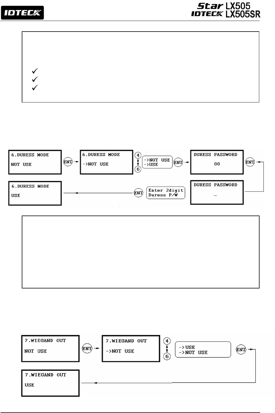
12.2.6 Duress Mode
12.2.7 Wiegand Output
You can set Duress Mode for Reader#1. The default setting is NOT USE. If you select USE,
the LCD will display the default Duress Password ‘00’. You can enter the desired 2-digit
Duress Password.
Note | While the LX505 is in the Duress condition, enter the 2-digit Duress Password
and press <ENT> key prior to presenting the card. The door will be opened as
usual, but the Duress Alarm will be generated and reported to the host PC.
CAUTION | The Duress password and ARM code and DISARM code must differ.
The Anti-pass back feature is used to prevent an identical user from entering or exiting the
door more than twice in a row. This mode can be applied only when an Exit Reader is
installed. Do not set this mode to USE if an Exit Button is not installed.
NOT USE: The Anti-pass back feature is disabled.
USE: The Anti-pass back feature is enabled.
ALL FLAG RESET: All Anti-pass back flags are reset, and access will be allowed one
time re
g
ardless of the status of the existin
g
fla
g
s.
39
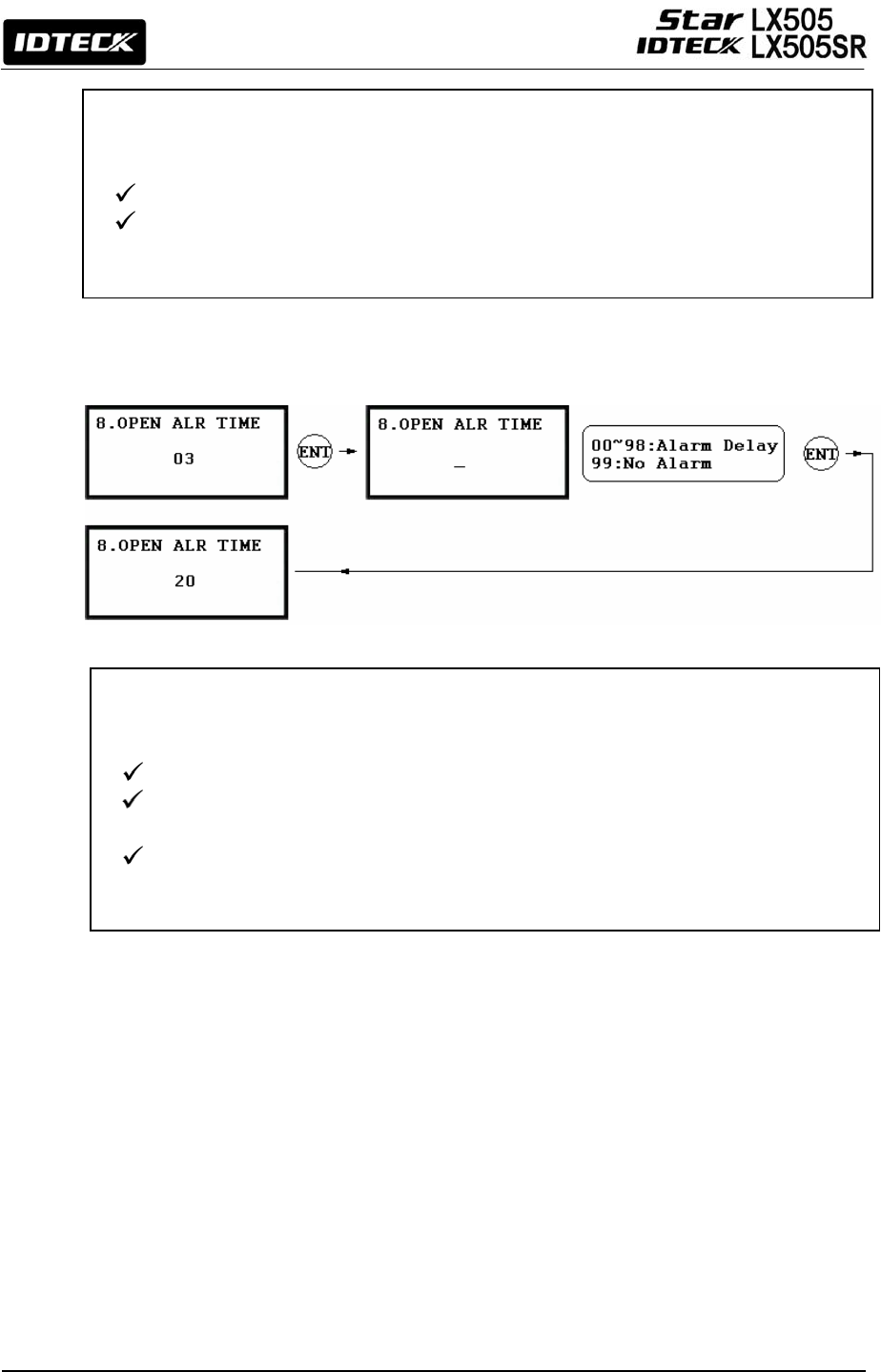
12.2.8 Door Open Alarm Time Setting
The ‘Door Open Alarm Delay’ is the time period between the Door Open Time and the point
at which the Door Open Alarm starts ringing.
00: The alarm will ring if the door isn’t closed after the Door Relay time.
01~98: The alarm will ring if the door is not closed after the door open time and over
the alarm delay time. (01~98 sec.)
99: No alarm.
Note
|
A Door Contact Sensor must be installed on the door for this a
pp
lication.
This feature allows you to use the LX505 as a reader (rather than as a controller). If this
setting is set to USE, the LX505 sends 26bit Wiegand Output through two TTL output ports.
NOT USE: Normal TTL outputs will be activated.
USE: 26bit Wiegand outputs will be generated through TTL1 and TTL2 ports. When a
registered card is read, the “CARD SCCANNING OK” message will appear on
the LCD. (TTL1 : Data 0 TTL2 : Data 1)
40
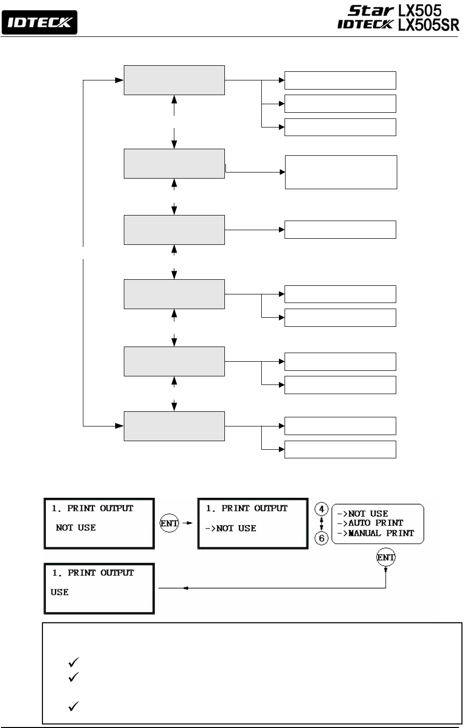
12.3 F3 SETUP MENU
12.3.1 Print Output
If connected to a serial printer, the LX505 can send the printer the details of new events
including ID, data, time, function key, etc.
AUTO PRINT: Print outputs are generated for every new event.
MANUAL PRINT: By pressing ‘0’ (no printing) or ‘1’ (printing) key, you can manually
select whether or not to print a new event.
NOT USE: No printing output.
ONE TIME READ
<4> or <6> KEY
PRINT OUTPUT
VOICE VOLUME
ARM/DISARM
<4> or <6> KEY
<4> or <6> KEY
<4> or <6> KEY
TWO MEN MODE
<4> or <6> KEY
NOT USE(DEFAULT)
AUTO PRINT
0(MUTE) - 4(MAXIMUM)
Enter a 2-digit code
NOT USE(DEFAULT)
USE
MAX. USER SETUP
<4> or <6> KEY
10,000(DEFAULT)
20,000
MANUAL PRINT
NOT USE(DEFAULT)
USE
41
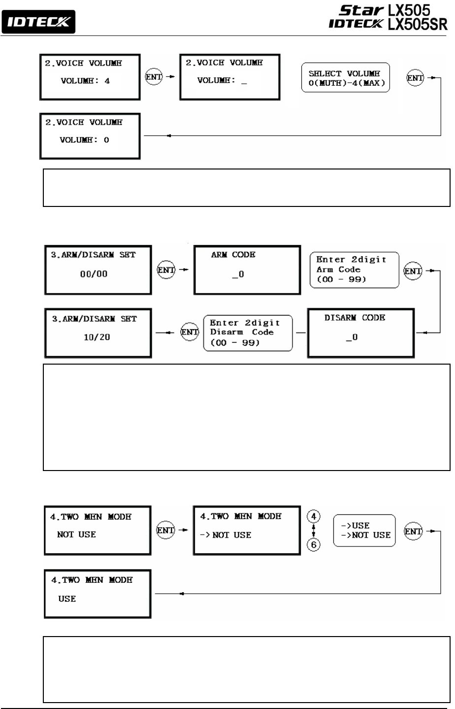
12.3.2 Voice Volume
12.3.3 Arm/Disarm
12.3.4 Two Men Mode
The LX505 tells you its status out loud. You can adjust the volume of the voice from 0 (mute)
to 4 (maximum). New voices can be downloaded through communications with the host PC.
This setting allows you to set the Arm Code and the Disarm Code. After setting the Arm
Code or Disarm Code, you can set the LX505 to the ARM mode by entering the ARM code
and presenting an ARM/DISARM card (i.e. a card that was registered with Code 3). In this
mode, the LX505 can generate outputs so that it can operate with other security systems.
Once this mode is set, all readers stop reading cards. To DISARM the LX505, enter the
Disarm Code and present an ARM/DISARM card.
CAUTION
|
The ARM Code, DISARM Code, and Duress Code must all differ.
To apply this feature, cards designated for guides should be registered into the Admin
Group(C:1) as ID(1) and visitor cards into the Visitor Group(C:2) as ID(2). If configured in the
two-man mode, the LX505 won't grant access until one ID(1) guide card and one ID(2)
visitor card are presented in a series within a certain time length.
42
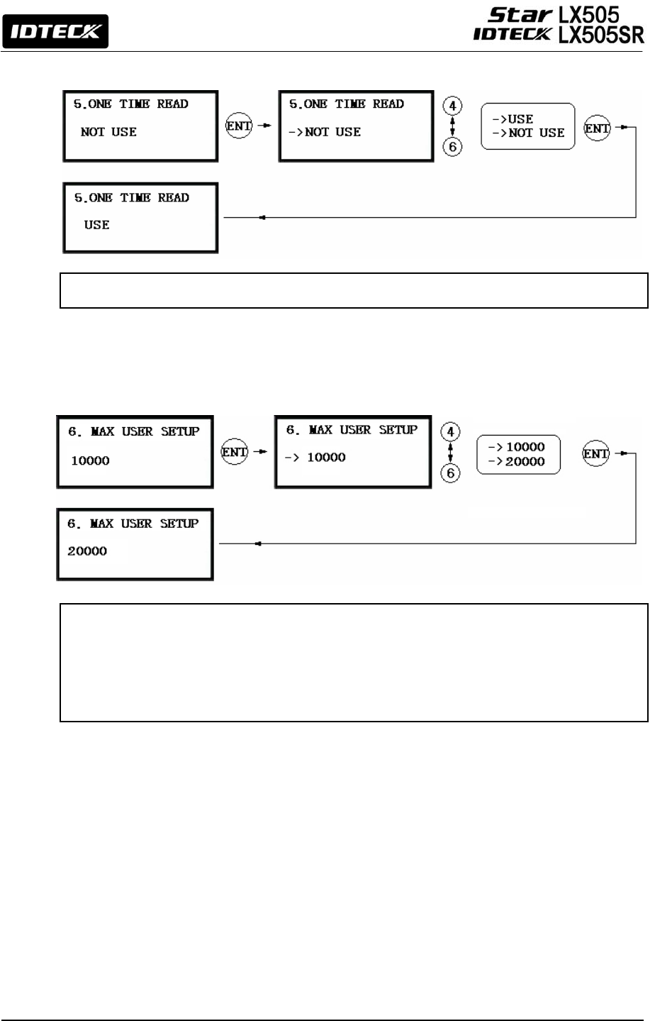
12.3.5 One Time Read
12.3.6 Max. User Setup
If this mode is set to USE, an identical ID won’t be read twice within 30 seconds.
You can select the maximum number of user registrations; 10,000 or 20,000. If the maximum
number of registrants is set to 20,000, the maximum number of event transactions becomes
10,000.
CAUTION: Before changing the maximum number of users, you should
initialize the device.
43
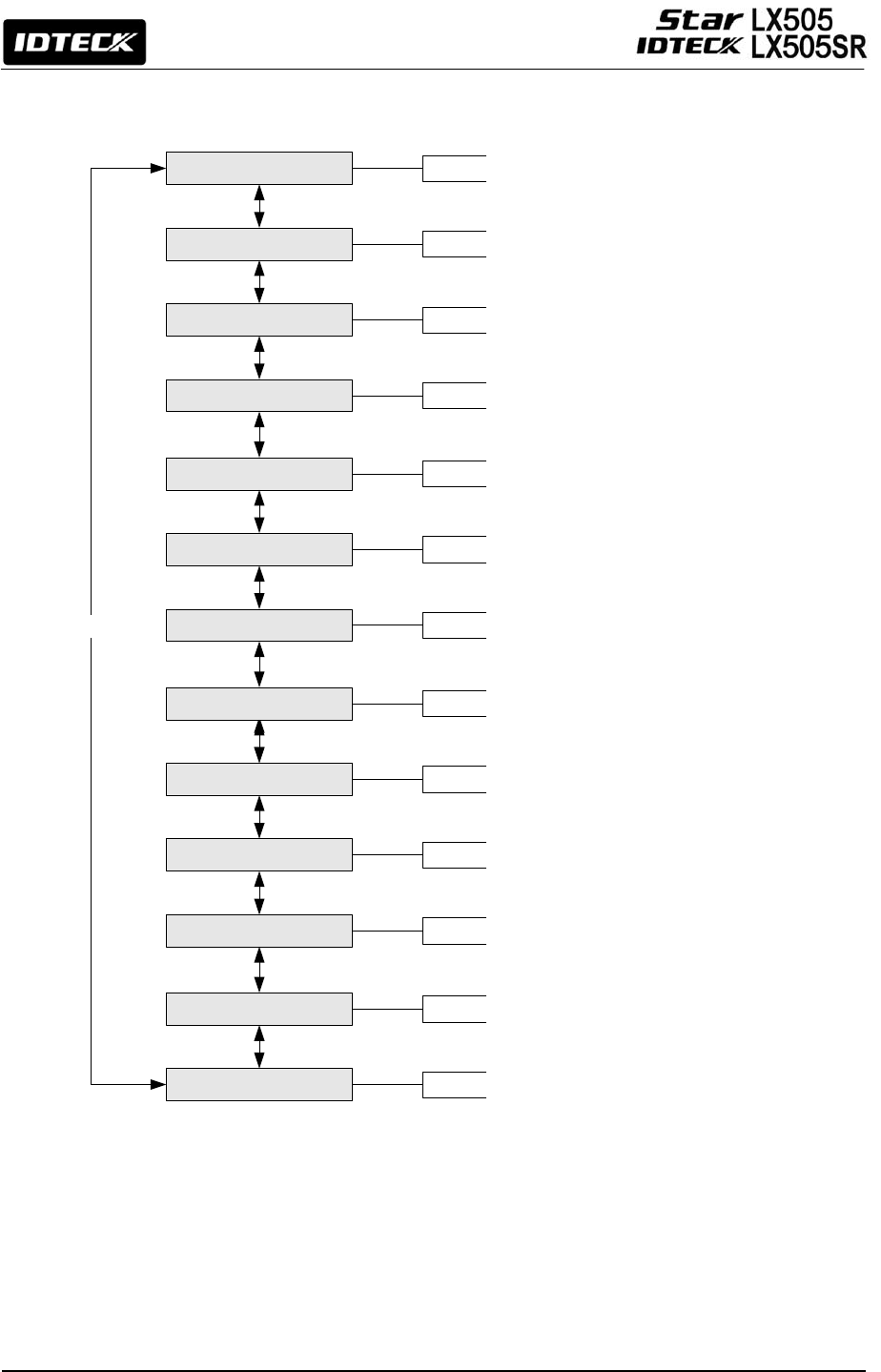
12.4 F4 SETUP MENU
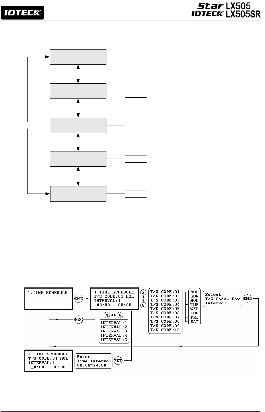
12.4.1 Time Schedule
TIME SCHEDULE
HOLIDAY
HOLIDAY CODE
<4> or <6> KEY
<4> or <6> KEY
<4> or <6> KEY
<4> or <6> KEY
RD1 MODE <-T/S
RD2 MODE <-T/S
<4> or <6> KEY
T/S/ CODE: 01 - 10
Weekly : 8 DAYS, HOL, SUN, MON, … , SAT
INTERVAL: 1- 10
H/S CODE: 01 - 10
HOLIDAYS: 001 - 100
HOLIDAY INDEX: 01
T/S CODE: 0 - 10
T/S CODE: 0 - 10
44
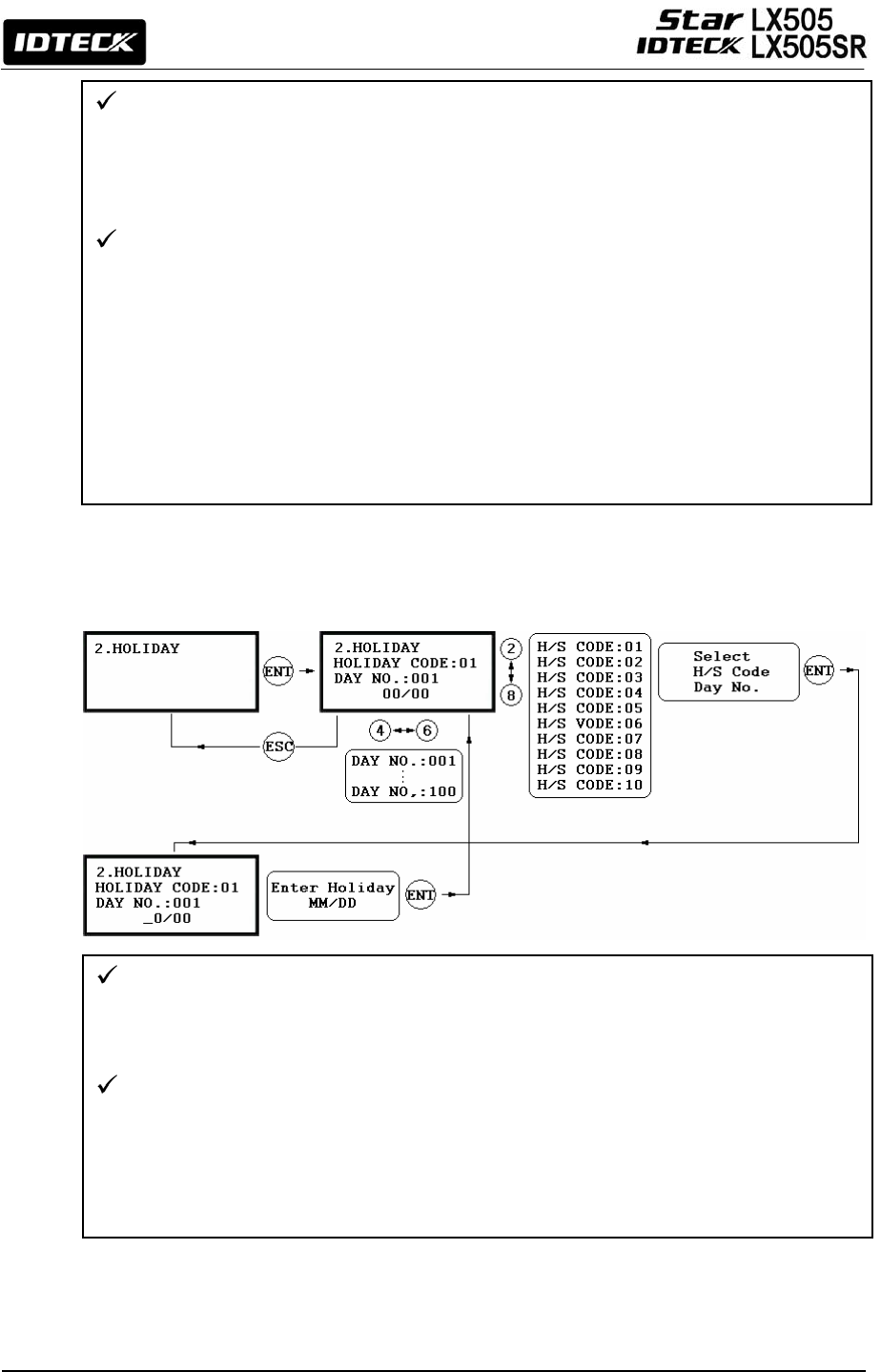
12.4.2 Holiday
There are 10 Time Schedule Codes available for users. Time Schedule Code “00” is the
default setting that allows access to all users at any time. The user can program the
Time Schedule Codes 01 to 10. Each Time Schedule Code has 8 programmable days (i.e.
Sun, Mon, Tue, Wed, Thu, Fri, Sat and Holiday) and each day has 5 Time Intervals (i.e.
Shift time or Accessible time zone.)
The LCD will show the current Time Schedule settings such as T/S Code, Day, Time
Interval and time period. Use <2> or <8> key to scroll up and down the Time Schedule
Code (01~10) and a day of the week. (Mon - Sun and Holiday). Use <4> or <6> key to
select Time Interval between 1 and 5. The Holiday in this Time Schedule will be linked
to the Holiday Schedule Code. Select one of the Time Schedule Code, Day and Interval,
and then press <ENT> key. This system is based on 24-hour system and therefore the
time 00:00 and 24:00 refer to the same time and 12:00 refers to 12 O’clock afternoon.
Enter the hour and minute of the start time and hour and minutes for end time of the
Time Interval then press <ENT> key to store T/S to the memory. Press <ESC> key to
return to the menu.
There are 10 Holiday Schedule Codes available for users. Holiday Schedule Code “00” is
the default code, which includes no Holidays in it. The user can program the Holiday
Schedule Codes 01 to 10. Each Holiday Schedule Code can have up to 100
programmable holidays.
The LCD will show current H/S settings including H/S Code, Holiday number and Date.
Use <2> or <8> key to scroll up and down from the Holiday Schedule Code 01 to 10 and
use <4> or <6> key to select from Holiday number 001 to 100.
Select one of the Holiday Schedule Code and Holiday number then press <ENT> key.
Enter the month and date of the holiday, then press <ENT> key to store the Holiday
Schedule to the memory. To return to the previous menu, press <ESC> key.
45
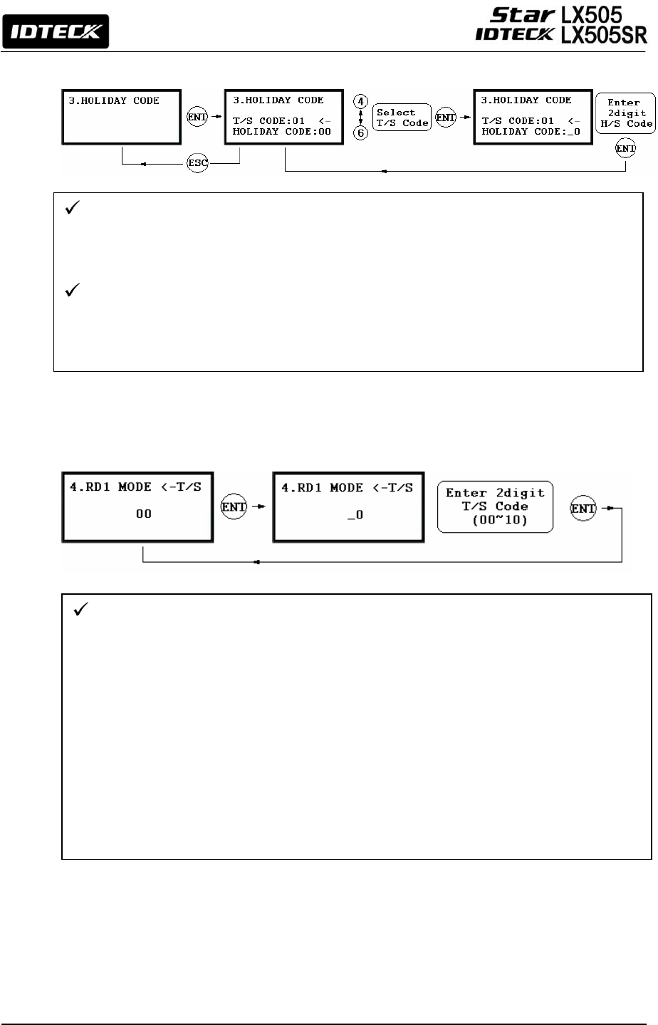
12.4.3 Holiday Code
12.4.4 Reader#1 Mode Time Schedule
12.4.5 Reader#2 Mode Time Schedule
The READER#2 MODE TIME SCHEDULE setting can be configured in the same way as
READER#1 MODE T/S setting, which is explained in the previous section.
The Holiday Code setting allows you to link a Holiday Schedule to a Time Schedule. A
Time Schedule has 5 Time Intervals for holidays and the Time Intervals are applied only
to the dates of this Holiday Schedule. The default Holiday Schedule Code is ‘00’ which
means no holidays are applied to the Time Schedule.
Use <4> or <6> key to scroll up and down from the T/S Code 01 to 10 and press <ENT>
key. Then, enter a 2-digit Holiday Schedule Code and press <ENT> key to store the
changed Holiday Index settings to the memory. To return to the previous menu, press
<ESC> key.
There are 2 system operations modes including RF Only Mode, RF+PW Mode. You can
select one of these system operations modes at [R1 MODE SETTING] from [F1 SETUP
MENU]. If, however, you want to apply a different operating mode to all users during a
certain Time Interval. For example, you may want to access the door by only presenting a
card from 09:00 to 17:00 and you want to use Password verification for the rest of the time.
Then, you can to do so by setting [R1 MODE SETTING] to RF+PW Mode, which is for the
system operating mode, and then program T/S Code 01 so it can include a Time Interval
between 09:00 and17:00. Then link the Time Schedule Code 01 to the R1 MODE Time
Schedule setting in this menu. To link a Time Schedule Code (01~10) to Reader#1 Mode,
first, press <ENT> key and get into the setting mode. Then, enter the 2-digit Time Schedule
Code and press <ENT> key to store and apply the Time Schedule Code to R1 MODE. To
return to the previous menu, press <ESC> key.
46
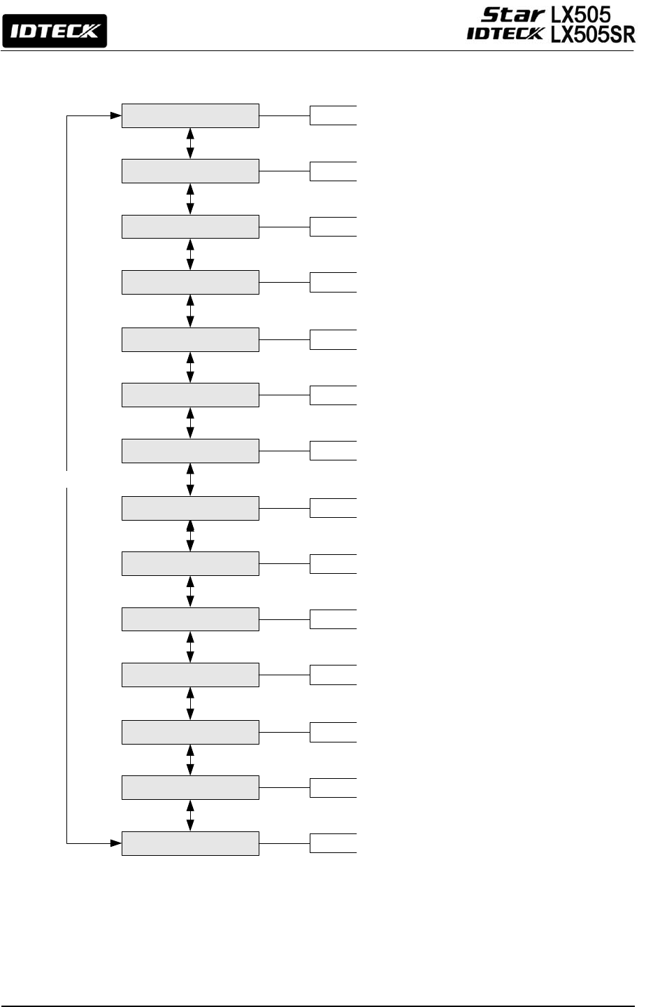
12.5 F5 SETUP MENU
TAMPER ALARM
<4> or <6> KEY
EXIT BUTTON
DOOR CONTACT
AUX INPUT #1
AUX INPUT #2
DR TIME OUT
CUT OFF ALARM
DURESS ALARM
CUT OFF CHECK
ARM/DISARM OUT
OUTPUT T/S
INPUT T/S
INPUT TYPE
Output operation time: 10 DIGITS
Output operation time: 10 DIGITS
Output operation time: 10 DIGITS
Output operation time: 10 DIGITS
Output operation time: 10 DIGITS
Output operation time: 10 DIGITS
Output operation time: 10 DIGITS
Output operation time: 10 DIGITS
Output operation time: 10 DIGITS
Output operation time: 10 DIGITS
Output operation time: 10 DIGITS
Output operation time: 10 DIGITS
Output operation time: 10 DIGITS
47
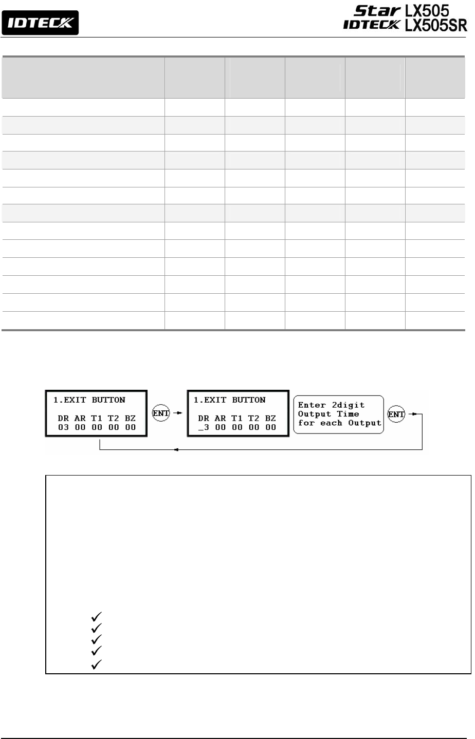
Default Output Settings for Input Sources
12.5.1 Exit Button Output Setting
OUTPUT
Door
Relay
(DR)
Alarm
Relay
(AR)
TTL#1
(T1)
TTL#2
(T2)
Buzzer
(BZ)
[1] EXIT BUTTON 03 00 00 00 00
[2] DOOR CONTACT 00 99 00 00 00
[3] AUX Input #1 00 00 00 00 00
[4] AUX Input #2 00 00 00 00 00
[5] TAMPER ALARM 00 99 99 99 99
[6] CUT OFF ALARM 00 00 00 00 00
[7] DURESS ALARM 00 00 00 00 00
[8] ARM/DISARM OUT 00 00 00 00 00
[9] DR TIME OUT 00 00 00 00 00
[10] OUTPUT TIME SCHEDULE 00 00 00 00 00
[11] INPUT TIME SCHEDULE 00 00 00 00 00
[12] CUT OFF CHECK 00 00 00 00 00
[13] INPUT TYPE 00 00 00 00 00
You can program the Output Activation Time, the length of time fo
r
which the output is activated
after the EXIT button is pressed.
Let’s say, we put ‘03’ for one of the fields, If the unit of time is set to ‘1 sec’, then the activation
time will be 3 seconds. If the unit of time is set to ‘0.1 sec’, then the activation time will be 0.3
seconds (or 300 ms.)
You can set the time somewhere between 00 and 98 seconds (or between 0.0 and 9.8 seconds
if the Time Unit is set to 0.1 sec.) If you put “99”, the corresponding output will be activated
forever until you reset the output.
DR: Door Relay Output
AR: Alarm Relay Output
T1: TTL#1 Output
T2: TTL#2 Output
BZ:
Buzzer Output
48
12.5.2 Door Contact Output Setting
12.5.3 Aux Input#1 Output Setting
12.5.4 Aux Input#2 Output Setting
12.5.5 Tamper Alarm Output Setting
12.5.6 Cut Off Alarm Output Setting
12.5.7 Duress Alarm Output Setting
12.5.8 Arm/Disarm Output Setting
12.5.9 DR TIME Output Setting
The rest of output activation time settings above can be configured in the same way
as the Exit Button Output Setting in the section 12.6.1, which means you can refer to
that section to get some idea as to how to do the configuration.
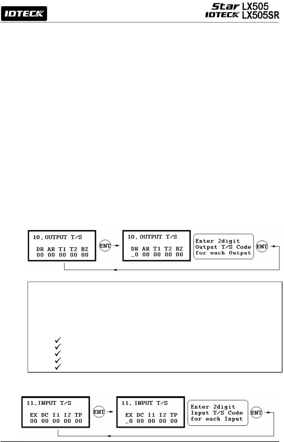
12.5.10 Output Time Schedule Setting
12.5.11 Input Time Schedule Setting
You can assign a Time Schedule Code to each output. The default Time Schedule Code for
every output is “00”, which means no Time Schedule is applied to them.
Changing these settings can be very useful when you want to open the door during a
certain Time Term. Press <ENT> key enter the setting mode and enter a 2-digit Time
Schedule Code for each output.
DR: Door Relay Output T/S Code
AR: Alarm Relay Output T/S Code
T1: TTL#1 Output T/S Code
T2: TTL#2 Output T/S Code
BZ:
Buzzer Output T/S Code
49
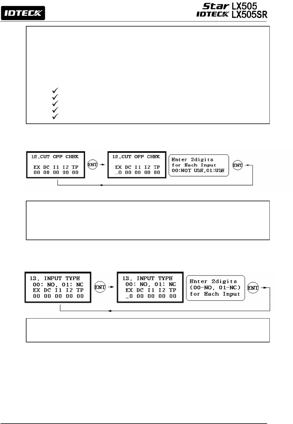
12.5.12 Cut Off Check Setting
12.5.13 Input Type Setting
You can assign a Time Schedule Code to each Input. The default Time Schedule Code for
every input is “00”, which means no Time Schedule is applied to them. Changing these
settings can be very useful when you want to activate PIR sensor input during a certain
period of time.
Press <ENT> key to enter this setting mode, then enter a 2-digit Time Schedule Code for
each input.
EX: EXIT Button Input T/S Code
DC: Door Contact Sensor Input T/S Code
I1: Aux Input#1 T/S Code
I2: Aux Input#2 T/S Code
TP: Tamper Switch Input T/S Code
You can choose whether or not to check the connection cutoff of each input port. ‘00’
means not using this feature and ‘01’ means using it.
CAUTION: Before setting this setting to USE, a 2.2K resistor should be connected
between the input wire and the GND.
You can program each input for either NO(Normally Open) or NC(Normally Close) operation.
‘00’ means NO while ‘01’ means NC. The default setting is 00(NO).
50
12.6 F6 SETUP MENU
RD1 ID ERROR
<4> or <6> KEY
RD1 ID OK LV1
RD1 ID OK LV2
RD1 ID OK LV3
RD1 ID OK LV4
RD2 ID OK LV2
RD1 T/S ERROR
RD1 APB ERROR
RD2 ID ERROR
RD2 ID OK LV1
RD2 ID OK LV3
RD2 ID OK LV4
RD2 T/S ERROR
RD2 APB ERROR
Output operation time: 10 DIGITS
Output operation time: 10 DIGITS
Output operation time: 10 DIGITS
Output operation time: 10 DIGITS
Output operation time: 10 DIGITS
Output operation time: 10 DIGITS
Output operation time: 10 DIGITS
Output operation time: 10 DIGITS
Output operation time: 10 DIGITS
Output operation time: 10 DIGITS
Output operation time: 10 DIGITS
Output operation time: 10 DIGITS
Output operation time: 10 DIGITS
Output operation time: 10 DIGITS
51
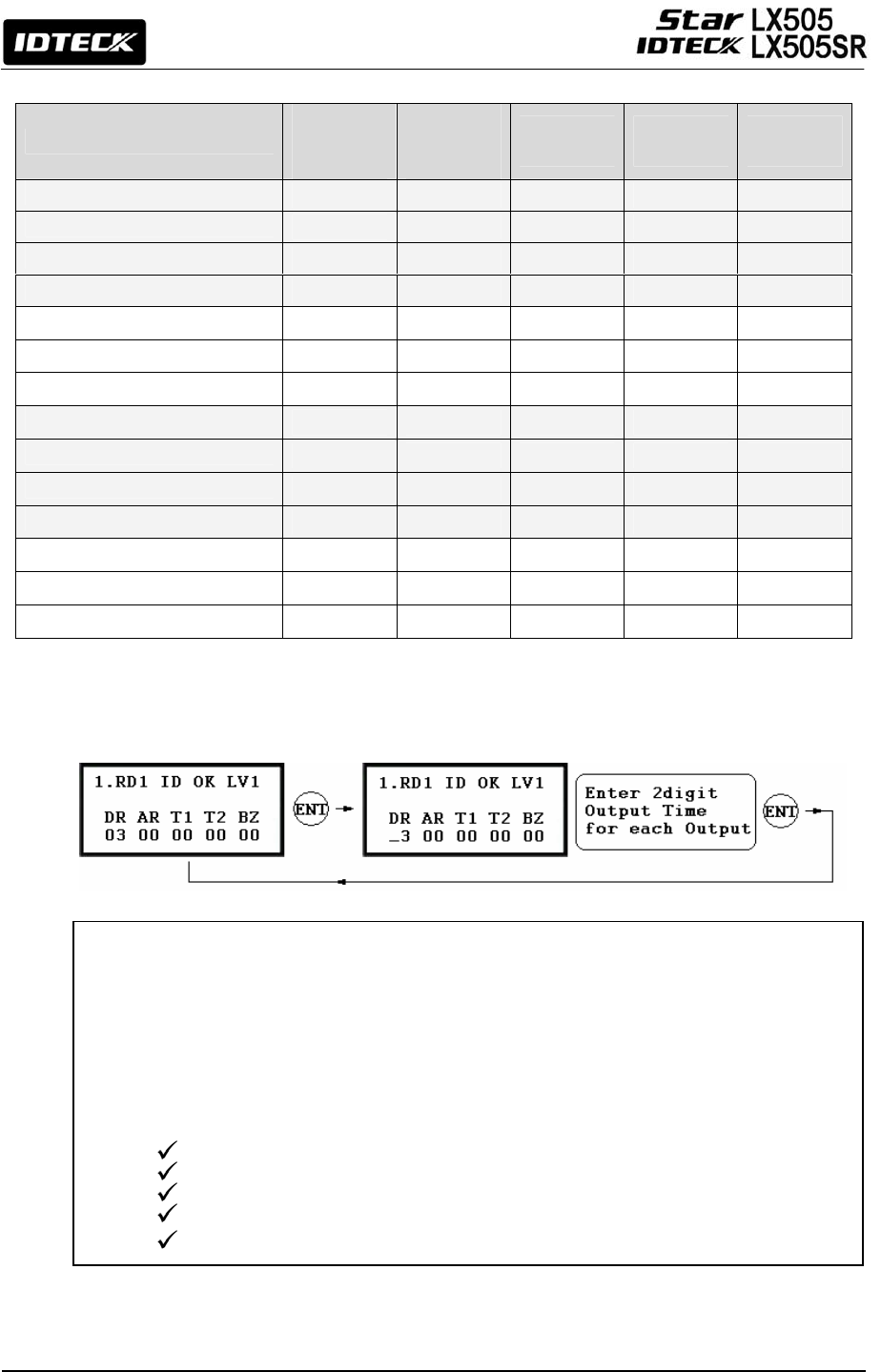
Default Output Setting for Different Inputs
12.6.1 Output Setting for Reader#1 ID OK Level 1
OUTPUT
Door
Relay
(DR)
Alarm
Relay
(AR)
TTL#1
(T1)
TTL#2
(T2)
Buzzer
(BZ)
[1] Reader#1 ID OK LV1 03 00 00 00 00
[2] Reader#1 ID OK LV2 05 00 00 00 00
[3] Reader#1 ID OK LV3 05 00 00 00 00
[4] Reader#1 ID OK LV4 05 00 00 00 00
[5] Reader#1 ID Error 00 03 00 00 00
[6] Reader#1 T/S Error 00 03 00 00 00
[7] Reader#1 APB Error 00 03 00 00 00
[8] Reader#2 ID OK LV1 03 00 00 00 00
[9] Reader#2 ID OK LV2 05 00 00 00 00
[10] Reader#2 ID OK LV3 05 00 00 00 00
[11] Reader#2 ID OK LV4 05 00 00 00 00
[12] Reader#2 ID Error 00 03 00 00 00
[13] Reader#2 T/S Error 00 03 00 00 00
[14] Reader#2 APB Error 00 03 00 00 00
You can program the Output Activation Time, the length of time during which the output is
activated after the EXIT button is pressed. The actual Output Activation Time equals either V
seconds, provided that the Time Unit is set to 1 second, or V/10 seconds, provided that the Time
Unit is set to 0.1 second. (V=Activation Time Value assigned for each output.)
You can set the time somewhere between 00 and 98 seconds (between 0.0 and 9.8 seconds if
the Time Unit is set to 0.1 sec.) If you put “99”, the corresponding output will be activated
forever until you reset the Output.
DR: Door Relay Output
AR: Alarm Relay Output
T1: TTL#1 Output
T2: TTL#2 Output
BZ: Buzzer Output

52
Output Time setting from 12.7.2 to 12.7.14 can be configured in the same
way as 12.7.1 RD1 ID OK Level 1 Output setting.
12.6.2 Output Setting for Reader#1 ID OK Level 2
This output time is applied for the users registered with Level#2 output.
12.6.3 Output Setting for Reader#1 ID OK Level 3
This output time is applied for the users registered with Level#3 output.
12.6.4 Output Setting for Reader#1 ID OK Level 4
This output time is applied for the users registered with Level#4 output.
12.6.5 Output Setting for Reader#1 ID Error
This output time is applied when a user that is not registered in Reader #1 attempts
access.
12.6.6 Output Setting for Reader#1 T/S Error
This output time is applied when a user attempts access before or after the time
assigned by the applied time schedule.
12.6.7 Output Setting for Reader#1 APB Error
This Output Time is applied when a user who attempts access has violated the one-
entry-one-exit rule of Anti-pass-back.
12.6.8 Output Setting for Reader#2 ID OK Level 1
This Output Time is applied for the users registered with Level#1 output.
12.6.9 Output Setting for Reader#2 ID OK Level 2
This Output Time is applied for the users registered with Level#2 output.
12.6.10 Output Setting for Reader#2 ID OK Level 3
This Output Time is applied for the users registered with Level#3 output.

53
12.6.11 Output Setting for Reader#2 ID OK Level 4
This Output Time is applied for the users registered with Level#4 output.
12.6.12 Output Setting for Reader#2 ID Error
This output time is applied when a user that is not registered in Reader #1 attempts
access.
12.6.13 Output Setting for Reader#2 T/S Error
This output time is applied when a user attempts access before or after the time
assigned by the applied time schedule.
12.6.14 Output Setting for Reader#2 APB Error
This Output Time is applied when a user who attempts access has violated the one-
entry-one-exit rule of Anti-pass back.
54
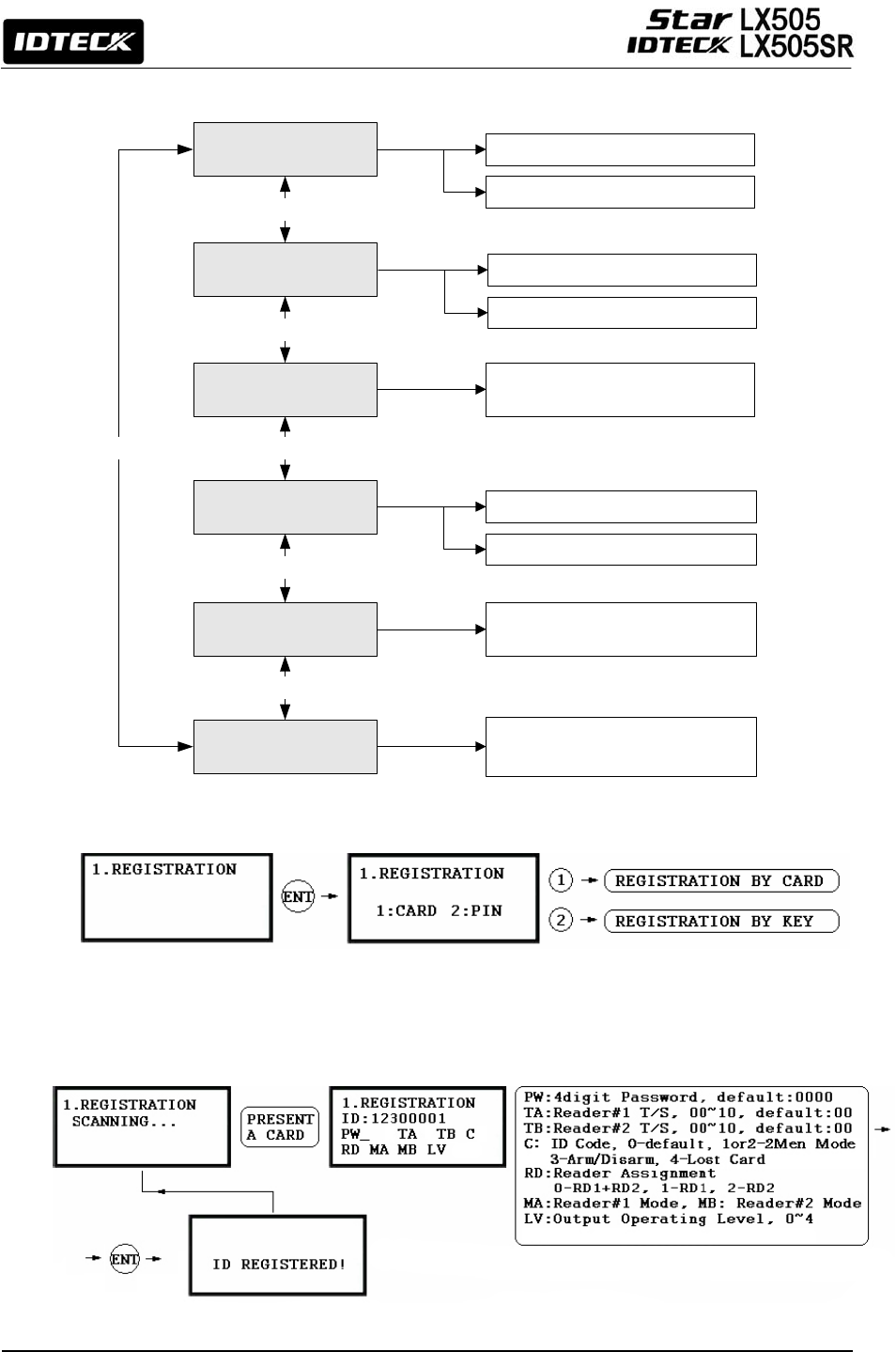
12.7 F7 SETUP MENU
12.7.1 ID Registration
a) Registration by Card
ID COUNT
EVENT COUNT
<4> or <6> KEY
<4> or <6> KEY
ID REGISTRATION
ID DELETION
ID LIST
<4> or <6> KEY
<4> or <6> KEY
<4> or <6> KEY
MASTER ID REG.
<4> or <6> KEY
CARD
KEY
CARD
KEY
REGISTERED IDs are displayed
NOT USE(DEFAULT)
USE
THE NUMBER OF REGISTERED IDs is
displayed
THE NUMBER OF STORED EVENTS is
displayed

55
b) Registration Using Keypad
NOTE| In case you make a typing mistake during the registration process, you can press F1
button to erase your errors.
1. Scanning – means the reader is waiting for an ID number to be entered. The card number
for the card will appear with a beep sound when you present the card.
2. ID – is a Personal Identification Number (PIN) that consists of 4-8 digits. Enter a 4-8digit ID
number (PIN) and press <ENT> key. (For LX505SR, the ID number consists of 4-10 digits.
3. PW – stands for a password that is required for verification in the RF + Password operating
mode.
4. TA – refers to the Time Schedule code (‘00’ ~ ‘10’) for the Reader#1 (i.e. the built-in
reader). Cardholders are granted access only during the Time Intervals of the Time
Schedule code entered to this TA field. To set the Time Intervals for each Time Schedule
code, refer to the instructions on the Time Schedule Setup in the [F4 SETUP MENU]. If
you want allow the cardholder access to the door anytime, then enter the default Time
Schedule code '00' for the value.
5. TB – refers to the Time Schedule code (‘00’ ~ ‘10’) for the Reader#2 (i.e. Exit Reader).
Cardholders are granted access only during the Time Intervals of the Time Schedule code
entered to this TB field. To set the Time Intervals for each Time Schedule code, refer to the
instructions on the Time Schedule Setup in the [F4 SETUP MENU]. If you want allow the
cardholder access to the door anytime, then enter the default Time Schedule code '00' for
the value.
6. RD – refers to the Reader Assignment code for the cardholder. Entering the code ‘0’
assigns both readers (Built-in Reader and Exit Reader) to grant access to the user that is
being registered, code ‘1’ only assigns Reader#1 (Built-in Reader) and code ‘2’ assigns
Reader#2 (Exit Reader). If you enter ‘1’ in the RD field(Only Reader#1 assigned) and try to
exit through Reader#2 (Exit Reader) then LX505 generates an error message (“Access Door
Error”) on the LCD display.
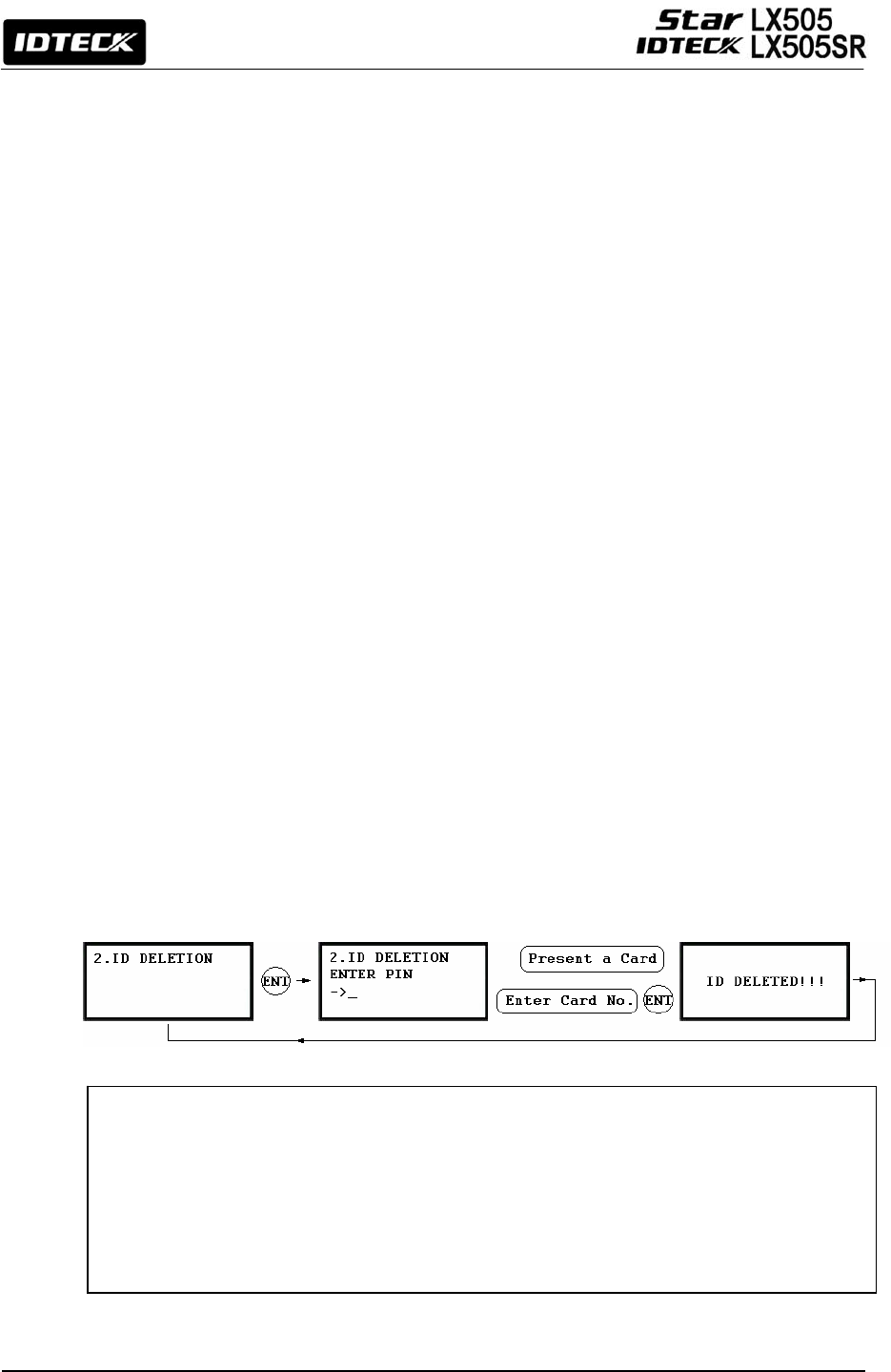
56
7. C – stands for the ID code. Code ‘0’ is default and code ‘1’ or ‘2’ is a code used for the
TWO MEN MODE. Code ‘3’ is used for the ARM/DISARM function and code ‘4’ is assigned
for lost cards.
8. MA – refers to the Operating Mode of the Reader#1 (i.e. the built-in reader) for the
cardholder. If you enter ‘1’ for MA, for example, Reader#1 will be operating always on RF
Only Mode.
• ‘0’ – System Operating Mode (Path: [F1 SETUP MENU] > [READER#1 MODE])
• ‘1’ – ID Only Mode
• ‘2’ – ID + Password Mode
9. MB – refers to the Operating Mode of the Reader#2 (Exit Reader) for the cardholder. If you
enter ‘1’ for MB, for example, Reader#2 will be operating always on RF Only Mode.
• ‘0’ – System Operating Mode (Path: [F1 SETUP MENU] > [READER#1 MODE])
• ‘1’ – ID Only Mode
• ‘2’ – ID + Password Mode
10. LV – refers to the Output Operating Level for the cardholder. Output operating time can be
set for each user. To configure an Output operating time for each level, refer to the
instructions on Output Setting in the [F6 SETUP MENU].
• ‘0’ or ‘1’ – Level #1
• ‘2’ – Level #2
• ‘3’ – Level #3
• ‘4’ – Level #4
•
12.7.2 ID Deletion
Registered IDs can be deleted from the LX505 by presenting the card or entering the ID
number. After entering the ID DELETION mode, present the card you want to delete.
Alternatively, you may enter an 8 digit ID number and press <ENT> key from the keypad.
The ID number will appear on the LCD and that ID will be removed from the device and the
“ID DELETED” message will be shown on the LCD. If the ID number is not found, the
“UNREGISTERED ID” message will appear. You can delete multiple IDs by repeating this
p
rocess.
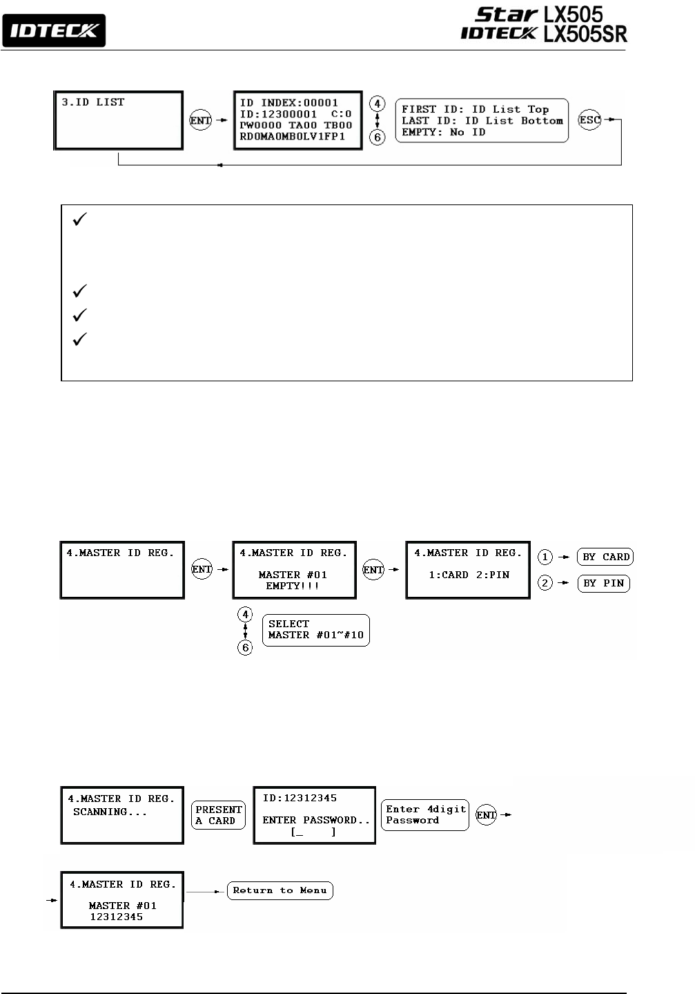
57
12.7.3 ID List
12.7.4 Master ID Registration
MASTER ID REGISTRATION BY CARD
The LCD will display the 5-digit ID Index, 8-digit ID numbe
r
, 4-digit Password, Timeschedule
for Reader#1(TA) and Reader#2(TB), ID code(C), accessible Readers(RD), operating mode for
Reader#1(MA) and Reader#2(MB), and the output level(LV).
The “EMPTY” message will appear if there is no registered user ID.
The “FIRST ID” message will be appear if the ID on the LCD is on the top of the list.
The “LAST ID” message will appear if the ID on the LCD is on the bottom of the list.
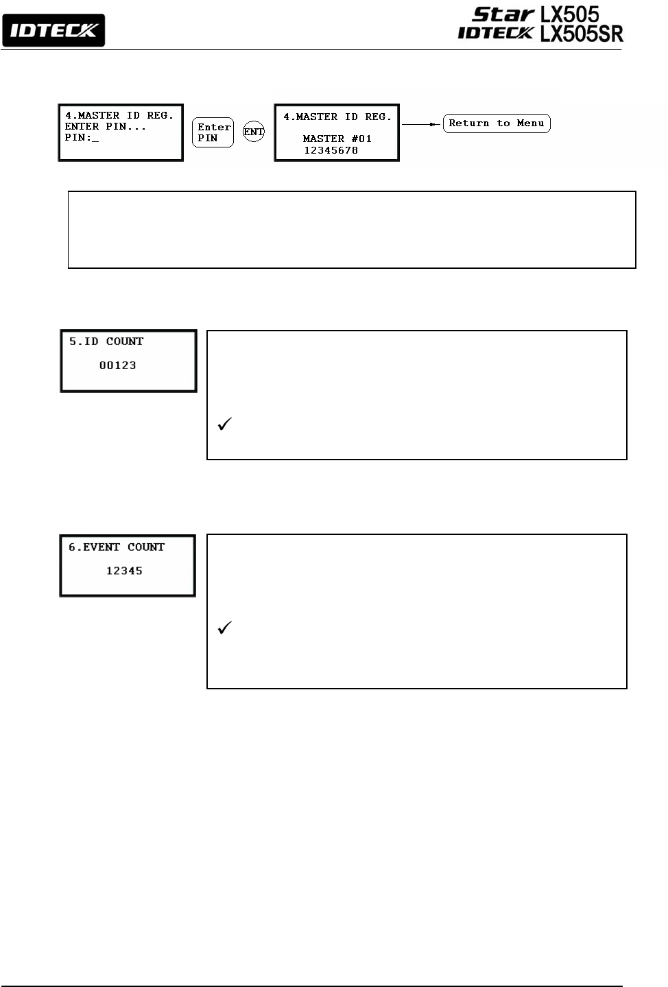
58
MASTER ID REGISTRATION BY PIN
12.7.5 ID Count
12.7.6 Event Count
The number of registered user IDs is displayed. This count
automatically increases or decreases as new IDs are registered or
old IDs are deleted. The LCD in the left picture shows that the total
of 123 user IDs are registered in the memory.
1,000 users in total can be registered (standard). You can
optionally choose to register up to 2,000/4,000 user IDs
The default Master ID #01 is “00000000” without a password.
For the LX505SR, it is ‘0000000000’.
Up to 10 Master IDs (from “01” to “10”) can be stored in the LX505.
The LCD displays the total number of events stored in the memory.
The count automatically increases as a new event is recorded in
the memory. The LCD in the left picture shows that a total of
12345 Events are stored in the memory.
Up to 20,000 event buffers are available. When stored events
are successfully uploaded to the host PC, they are
automatically deleted from the device.
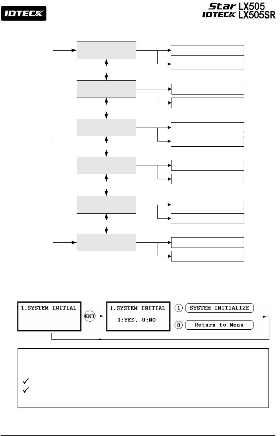
59
12.8 F8 SETUP MENU
12.8.1 System Initialize
This operation is used to initialize the LX505 system. Press <ENT> key for initialization
(when installing LX007 first or when resetting the system in the event of malfunction).
CAUTION: Initializing will erase all stored data in the memory.
Press the <1> key to initialize or <0> key to cancel the operation.
The “WAIT..” message appears while the system is being initialized. After the
initialization is completed, the LX007 returns to the Setup menu.
T/S CLEAR
DEFAULT SET
<4> or <6> KEY
<4> or <6> KEY
SYSTEM INITIAL
EVENT CLEAR
ID CLEAR
<4> or <6> KEY
<4> or <6> KEY
<4> or <6> KEY
MASTER ID CLR
<4> or <6> KEY
YES
NO
YES
NO
YES
NO
YES
NO
YES
NO
YES
NO
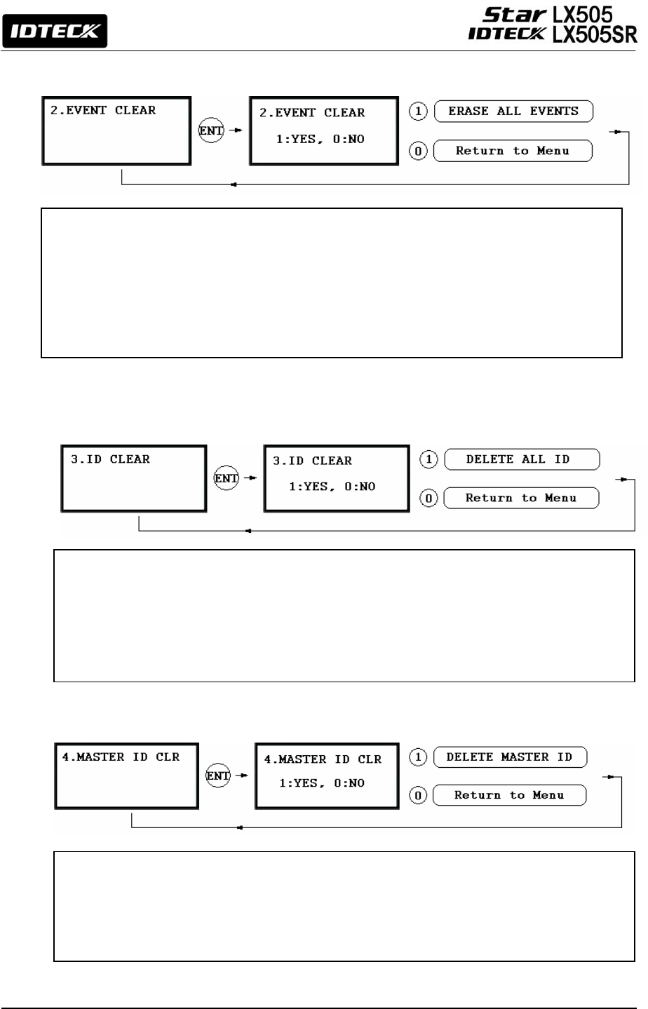
60
If the event memory is full or if you want to change the ID COUNT, you can clear the event
memory here.
Press <ENT> key first, then press <1> key to clear event memory or <0> key to cancel the
operation.
CAUTION: Before you clear the events, make sure if the stored events are
really unnecessary and therefore you don’t need to upload them to
t
h
e
h
os
t P
C
.
O
th
e
rwi
se,
you
m
ay
l
ose
im
po
rt
a
nt
da
t
a
.
12.8.2 Event Clear
12.8.3 ID Clear
12.8.4 MASTER ID CLEAR
When you want to delete all the stored User IDs (Card IDs), you can do so in this menu.
Press <ENT> key first, then press <1> key to clear all the registered User IDs or <0> key to
cancel the operation.
CAUTION: Before clearing all the User IDs, make sure that the registered User
ID is no longer used or necessary. Otherwise you may lose all the
re
g
istered User IDs.
To delete all Master IDs, press <ENT> key first, then press the <1> key to clear all of the
Master IDs or <0> key to cancel the operation.
CAUTION: Before clearing all Master IDs, make sure that registered Master
IDs are no longer used. Otherwise, you may lose all registered
Master IDs.
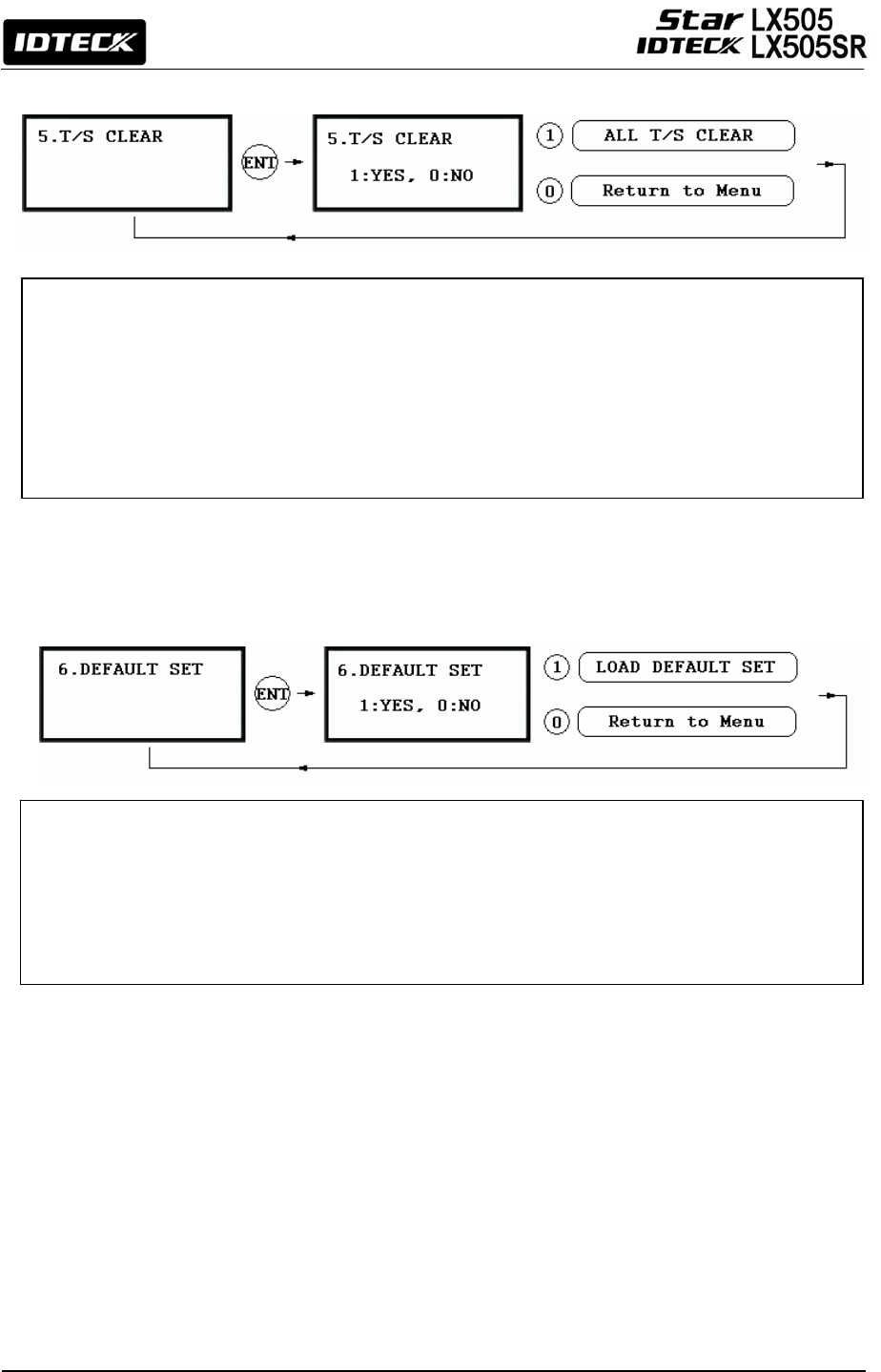
61
9.8.5 TIME SCHEDULE CLEAR
9.8.6 DEFAULT SETTING
When you want to delete all the Time Schedules (01~10), Holiday schedules(01~10), Holiday code,
Reader#1 Mode Time Schedule code and Reader#1 Mode Time Schedule code, you can clear them
from the memory here. Press <ENT> key first and press the <1> key to clear all T/S or <0> key to
cancel the operation.
CAUTION: Before you clear all Time Schedule data, make sure that the stored Time
Schedule data are no longer used or necessary. Otherwise, you may lose
all stored Time Schedule data in the memory including important ones.
Here, you can restore the default settings of the LX505, if necessary. Press <ENT> key and press
<1> key to restore the default setting values for all menus and or <0> key to cancel the operation.
CAUTION: Before restoring default values for all settings such as Reader Mode,
Board ID etc, make sure that the stored setting values are not necessary.
Otherwise, you may lose all system setting values in the memory and
need to adjust the settings all over again.
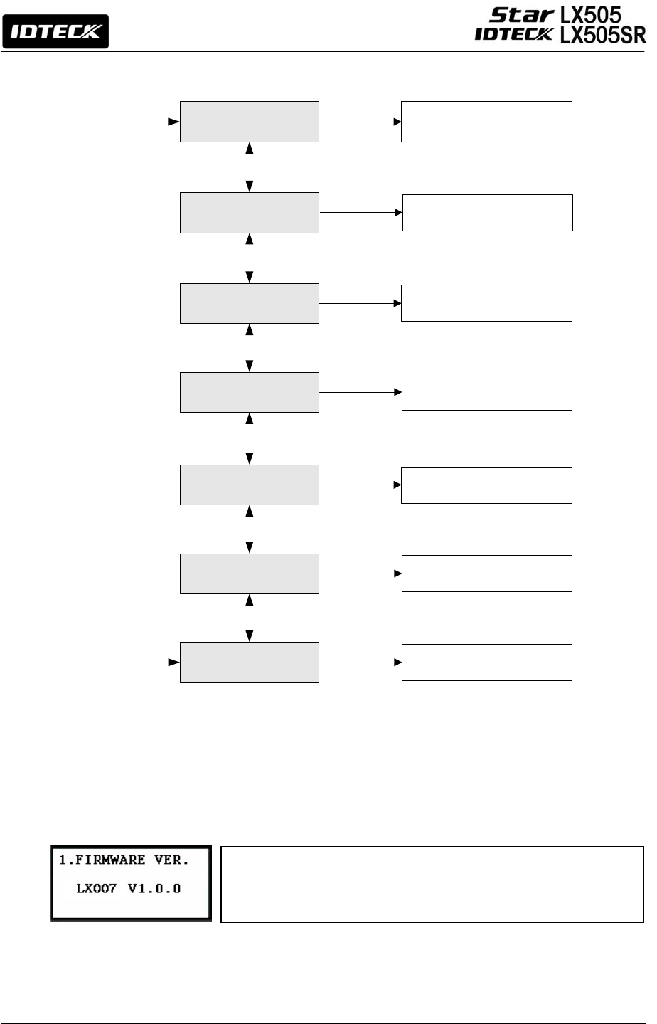
62
The Firmware Version of the LX505 is displayed on the LCD.
Press <4> or <6> key to take a look at other menus on [F9
SETUP MENU].
12.9 F9 SETUP MENU
12.9.1 Version Check
KEYPAD TEST
READER TEST
<4> or <6> KEY
<4> or <6> KEY
FIRMWARE VER.
INPUT TEST
OUTPUT TEST
<4> or <6> KEY
<4> or <6> KEY
<4> or <6> KEY
LCD TEST
<4> or <6> KEY
THE CURRENT VERSION OF
FIRMWARE IS DISPLAYED
VERIFY THAT THE INPUT
PORTS PROPERLY WORK.
MEMORY TEST
<4> or <6> KEY
VERIFY THAT THE OUTPUT
PORTS PROPERLY WORK.
VERIFY THAT THE LCD SCREEN
PROPERLY WORKS.
VERIFY THAT ALL THE KEYS ON
THE KEYPAD WORK.
VERIFY THAT THE READER
PROPERLY WORKS.
VERIFY THAT THE MEMORY
PROPERLY WORKS.
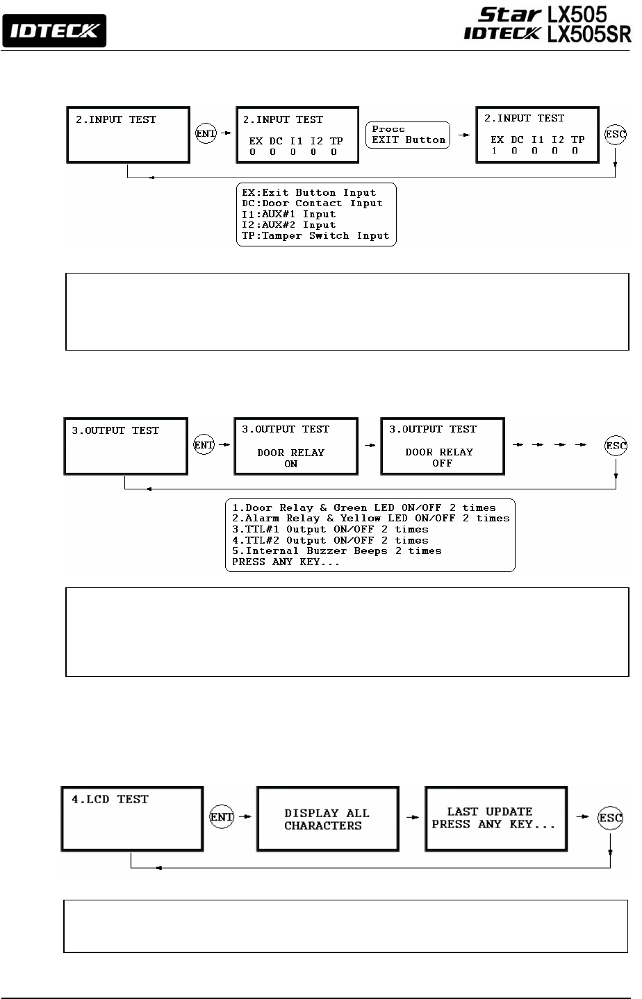
63
12.9.2 Input Test
12.9.3 Output Test
12.9.4 LCD Test
The 5-digit number shows the input status, where “0” indicates that the input port is
open circuit, and “1” indicates that the input port is short circuit to the ground level, and,
finally, “2” indicates that the input port is disconnected.
The first two tests verify the output relays (Door Relay and Alarm Relay) are working
properly. You can hear the mechanical sound of relays and see the LED blink. The next
two tests are to verify TTL#1 and TTL#2 outputs. Finally, the last test is for an Internal
Buzzer test. You can hear two bee
p
s durin
g
the test.
The LCD will display all possible characters on the screen. When the test is over, the LCD
will show the “LAST UPDATE PRESS ANY KEY” message.
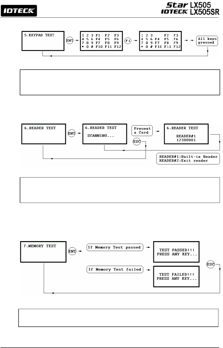
64
12.9.5 Keypad Test
12.9.6 Reader Test
12.9.7 Memory Test
The LCD will display all the keys on the keypad. Press each key one by one and the
depressed key will disappear from the screen. Note that ENT key is represented as “#” and
ESC key as “*” on the LCD.
The LCD will display “Scanning…”, which means the LX505 is waiting for a card to be
presented. Present a card to one of the readers. When the reader successfully reads the
card, the LCD displays the Reader number and the 8-digit card number.
If the Data Memory has a problem, the LCD will show the “TEST FAILED” message. If this is
the case, contact IDTECK or a nearby distributor for technical supports.

65
APPENDIX
A. THE RELATION BETWEEN INPUT AND OUTPUT (DEFAULT)
Default Output Settings for Input Sources
* Index No. [1] ~ [9]
The values indicate the operating time (second) of each output for the input signal.
* Index No. [10]
The values indicate the time schedule code (index) applied to each output operation.
* Index No. [11]
The values indicate the time schedule code (index) applied to each input from #1(Exit
button) to #5.
* Index No. [12]
The values indicate whether or not to use the cut off check feature.
(0 – NOT USE, 1 – USE)
* Index No. [12]
The values indicate whether the input type is NO(Normally Open) or NC(Normally Closed).
(0 – NO, 1 – NC)
OUTPUT
Door
Relay
(DR)
Alarm
Relay
(AR)
TTL#1
(T1)
TTL#2
(T2)
Buzzer
(BZ)
[1] EXIT BUTTON 03 00 00 00 00
[2] DOOR CONTACT 00 99 00 00 00
[3] AUX Input #1 00 00 00 00 00
[4] AUX Input #2 00 00 00 00 00
[5] TAMPER ALARM 00 99 99 99 99
[6] CUT OFF ALARM 00 00 00 00 00
[7] DURESS ALARM 00 00 00 00 00
[8] ARM/DISARM OUT 00 00 00 00 00
[9] DR TIME OUT 00 00 00 00 00
[10] OUTPUT TIME SCHEDULE 00 00 00 00 00
[11] INPUT TIME SCHEDULE 00 00 00 00 00
[12] CUT OFF CHECK 00 00 00 00 00
[13] INPUT TYPE 00 00 00 00 00

66
Default Output Settings for Input Circumstance
* Index No. [1] ~ [14]:
The values indicate the operations time (second) of each output for
the input signal.
OUTPUT
INPUT
Door
Relay
(DR)
Alarm
Relay
(AR)
TTL#1
(T1)
TTL#2
(T2)
Buzzer
(BZ)
[1] Reader#1 ID OK LV1 03 00 00 00 00
[2] Reader#1 ID OK LV2 05 00 00 00 00
[3] Reader#1 ID OK LV3 05 00 00 00 00
[4] Reader#1 ID OK LV4 05 00 00 00 00
[5] Reader#1 ID Error 00 03 00 00 00
[6] Reader#1 T/S Error 00 03 00 00 00
[7] Reader#1 APB Error 00 03 00 00 00
[8] Reader#2 ID OK LV1 03 00 00 00 00
[9] Reader#2 ID OK LV2 05 00 00 00 00
[10] Reader#2 ID OK LV3 05 00 00 00 00
[11] Reader#2 ID OK LV4 05 00 00 00 00
[12] Reader#2 ID Error 00 03 00 00 00
[13] Reader#2 T/S Error 00 03 00 00 00
[14] Reader#2 APB Error 00 03 00 00 00

67
B. TROUBLE SHOOTING
☞ A valid card became unregistered after batch-downloading IDs from PC.
Cause Wrong download procedure or a component defect.
Solution
1. The card ID might be registered only to the controller and not in the PC. During the
process of batch-downloading IDs from the PC, LX505 first erases the ID memory in it.
That’s why this deletion of certain IDs can happen if those IDs are not registered on the
PC.
2. Check whether the card ID is registered in the PC.
3. If not, please register the number and try downloading again.
4. If the trouble remains after following the procedures above, contact a designated
service center.
☞ I entered the Master ID “00000000” but I still cannot enter the Setup Mode.
Cause The Master ID might have been changed or some components are defective.
Solution
1. Try changing the Master ID through the application software.
(The Master ID will be changed to the default value “00000000”.)
2. When it is not feasible, initialize the unit as following:
After the installation and connections are completed, supply power (+12V DC) to LX505
with the initialization button being held down. Then, the LCD will first display
“Initialize OK? 0:No 1:Yes”. Press <1> key if you want to initialize the system. After
all the initialization process is completed, the system will be operating on the normal
mode and the LCD will display “IDTECK, LX505 [F1], Date Time”.
3. If the trouble remains after following the procedures above, contact a designated
service center.
☞ No problem with accessing by card, but cannot access via a manual PIN input.
Cause An error in the settings or possible component defect.
Solution
1. Check whether a beep sounds when you press a key. If a beep sounds, the problem may
be wrong settings. Proceed as followings:
- Enter the Master ID (Default=“00000000”) to get into the Setup mode.
- Press <F2> key.
- [LANGUAGE] will appear on the LCD, then use the <6> key to choose
[RD1_PIN_INPUT] and press [ENT] key to modify the value to ‘USE’ by using <4> or
<6> key.
2. When there is no beep sound or the problem persists after the keypad has been
enabled, contact a designated service center.
☞ I suddenly go back from the Setup mode to the normal operations mode.
Cause Time-out error
Solution LX505 is originally programmed to go back to the normal operations mode when no keys
are pressed or no cards are read within 60 seconds.

68
☞ The buzzer keeps beeping; “beep~ beep ~ beep” or “beeeeeeeep~~~~”.
Cause An error in the Installation, Door status or Internal circuits.
Solution
1. Check the door status. It occurs when the door is opened over 3 sec (Default).
2. Check the door contact sensor type: it must be NO/NC type.
3. Check the 10 Time schedule code (01~10) values of output T/S, in [7. OUTPUT T/S] of F6
Setup Menu. This problem can occur If the time schedule code is set between 01 and
10 or if the present time is in the schedule. If the time schedule is set to a unintended
value, change it to “00” (Programmable via PC software)
4. Check the Tamper switch of LX505.
5. If the trouble remains after checking the above, contact a designated service center.
☞ The “SCHEDULE ERROR” message shows when RFID card is read.
Cause An error in RFID card registration, time schedule setting or the system itself.
Solution
1. If the LX505 used to be properly operating before, it is guessed that there has been an
electric shock that damaged the internal memory and data. Please initialize the unit as
instructed in the manual.
2. Check if the registered ID information has been configured incorrectly.
* Register ID again and check the following points.
- In order to restrict access of a user within a specific time zone as instructed in the
manual, register time schedule in advance and apply the time schedule code(1~10) to
the user during the registration process.
- In order to allow the user to access at all times, put in “00”.
3. Use the software for time schedule settings if it LX505 is connected to PC as the
software manual.
4. If the trouble remains after checking the above, contact a designated service center.
☞ The “ACCESS DOOR ERR” message shows when an RF ID card is read.
Cause Incorrect user setting or something wrong with internal circuits.
Solution
1. If the LX505 used to operate properly before, it is guessed that there has been an
electric shock that damaged the internal memory and data. Please initialize the unit as
instructed in the manual. 2. Check if ID information has been put in incorrectly during
its registration.
* Register ID again and check the following points:
- Since the controller has two reader ports, set the “RD” setting – the door to which the
user will be allowed access – to an appropriate value.
- If the value for RD is set to “1”, the door opens only when Reader 1 reads a card. If the
card is presented to Reader 2, the “ACCESS DOOR ERROR” message appears.
- If the value for RD is set to “2”, the door opens only when Reader 2 reads a card. If the
card is presented to Reader 1, the “ACCESS DOOR ERROR” message appears.
- If RD is set to “0 or 3”, both the reader 1 and 2 open each door.
3. If the trouble remains after checking the above, contact a designated service center.
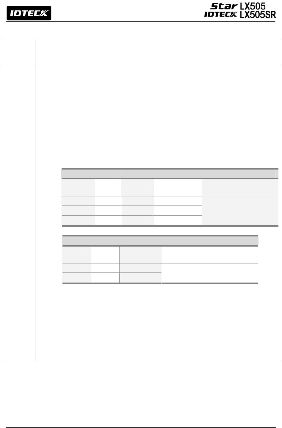
69
☞ The communication between the LX505 and the Host PC fails.
Cause
A defective cable may be used or errors in wiring, setting COMM ID of the controller, or
damage on the communication port (either on the PC side or the controller side) may also
cause the communication inability.
Solution
1. Please check the settings of the application software and the controller.
- Check if the COMM ID of the controller is listed on the application software.
- Set the different COMM ID when two or more controllers are installed.
- Check if the communication speed (9600bps is default) is the same as the setting on
the software.
- Make sure that the PC’s COM port is set correctly on the S/W.
- The parameters in the software should be set as following:
Parity bit : NONE
Data bit : 8bit
Stop bit : 1bit
2. Check the line connection for communication.
RS232 RS485 (mono)
LX505 PC LX505 RS485/232
Converter PC
RX TX RTX(-) RTX(-)
TX RX RTX(+) RTX(+)
GND GND
The RS232 cable from the
converter
RS485(Multi Drop)
LX505 LX505 RS485/232
Converter PC
RTX(-) RTX(-) RTX(-)
RTX(+) RTX(+) RTX(+)
The RS232 cable from
the converter
3. We recommend you to use line-end resistors of 120 Ohm between the RTX (+) and RTX
(-) lines when you are using the RS485 communication,. Apply the same resistors to the
converter RS485 lines. Consult a service center or an electric technician if you are not
sure how to do it.
4. When a multi-drop communication doesn’t work, test one-by-one communication first.
5. If the trouble remains after following the procedures above, contact a designated
service center.

70
FCC REGISTRATION INFORMATION
FCC REQUIREMENTS PART 15
Caution: Any changes or modifications in construction of this device which are not expressly
approved by the manufacturer for compliance could void the user's authority to operate the
equipment.
NOTE: This device complies with Part 15 of the FCC Rules.
Operation is subject to the following two conditions;
1. This device may not cause harmful interference, and
2. This device must accept any interference received, including interference that may cause
undesired operation.
This equipment has been tested and found to comply with the limits for a Class A Digital Device,
pursuant to Part 15 of the FCC Rules. These limits are designed to this equipment generates, uses,
and can radiate radio frequency energy and, if not installed and used in accordance with the
instructions, may cause harmful interference to radio communications.
However, there is no guarantee that interference will not occur in a particular installation. If this
equipment does cause harmful interference to radio or television reception, which can be determined
by turning the radio or television off and on, the user is encouraged to try to correct interference by
one or more of the following measures.
1. Reorient or relocate the receiving antenna.
2. Increase the separation between the equipment and receiver.
3. Connect the equipment into an outlet on another circuit.
4. Consult the dealer or an experienced radio/TV technician for help.

71
Warranty and Service
The following warranty and service information applies only to the United States of America and
Republic of Korea. For the information in other countries, please contact your local distributor.
To obtain in or out of warranty service, please prepay shipment and return the unit to the service
facility listed below.
Headquarters: IDTECK Co., Ltd.
5F Ace Techno Tower B/D,
684-1 Deungchon-Dong, Gangseo-Gu,
SEOUL, KOREA 157-030
Tel: +82-2-2659-0055
Fax: +82-2-2659-0086
E-mail: webmaster@idteck.com
Website: www.idteck.com
U.S Branch: RF Logics Inc.
370 Amapola Ave, #106
Torrance, CA 90501
Tel: 310-782-8383
Fax: 310-782-8298
E-mail: rflogics@rflogics.com
Website: www.rflogics.com
Hong Kong Branch: IDTECK Hong Kong
12/F, B2B Centre, No.36 Connaught Road West, Hong Kong
Tel: 852-2581-9580
Fax: 852-2234-5150
E-mail: alchu@qala.com.hk
Website: www.ristarhk.com
Please use the original container, or pack the unit(s) in a sturdy carton with sufficient packing to
prevent damage and include the following information:
1. A proof-of-purchase indicating model number and date of purchase.
2. Bill-to Address.
3. Ship-to Address.
4. Number and description of units shipped.
5. Name and telephone number of person to be contacted.
6. Reason for return and description of the problem (Should be as detailed as possible!)
NOTE: Damage occurring during shipment is the responsibility of the carrier, and claims should
be made directly to the carrier.

72
The specifications contained in this manual are subject to change without notice at any time.
5F, Ace Techno Tower B/D, 684-1, Deungchon-Dong,
Gangseo-Gu, Seoul, 157-030, Korea
Tel : +82-2-2659-0055
Fax : +82-2-2659-0086
E-mail : webmaster@idteck.com
Nov. 2006 Copyright ©2006 IDTECK Co., Ltd.
MAML007HE1X