ID Teck Co STARRF-TINY Proximity Reader ( RF-Tiny) User Manual 285773
ID-Teck Co Ltd Proximity Reader ( RF-Tiny) 285773
UserManual.wiki
>
ID Teck Co
>
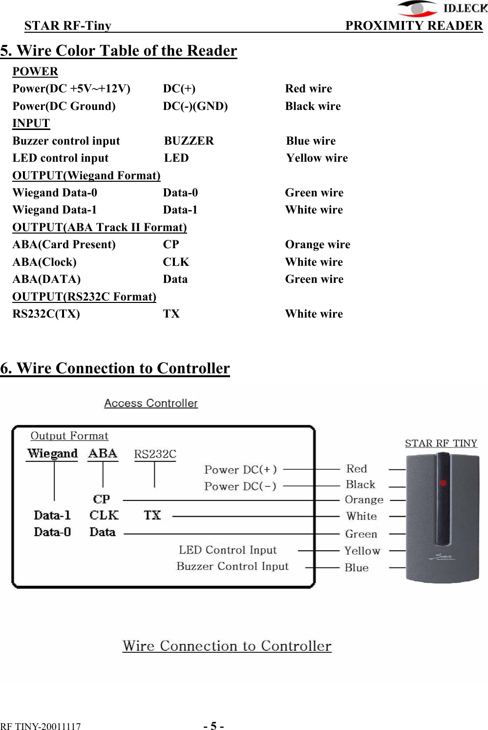
STARRF TINY User Manual
User Manual
Navigation menu
Upload a User Manual
Namespaces
Wiki Guide
HTML
PDF
Info
Views
User Manual
Discussion / Help
Navigation