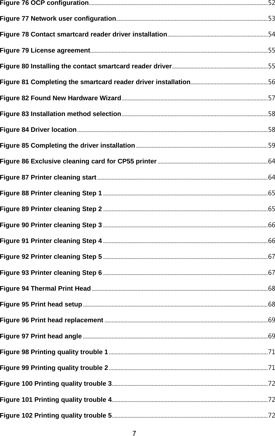
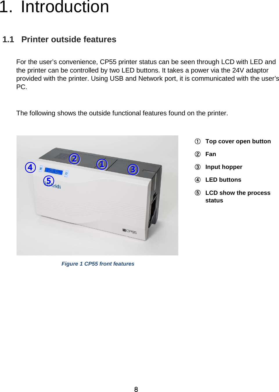
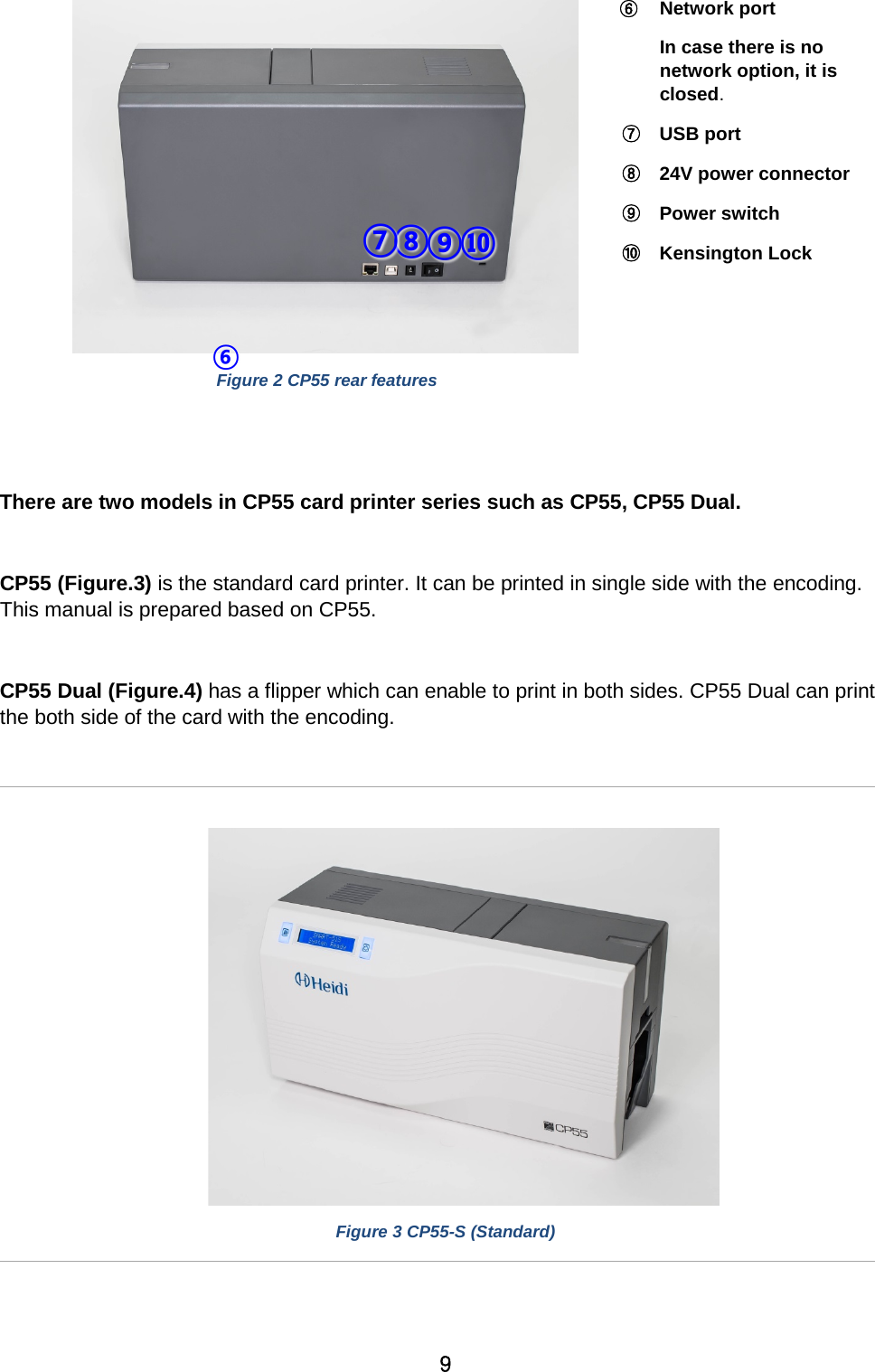
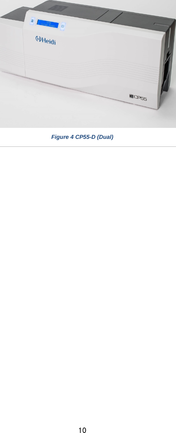
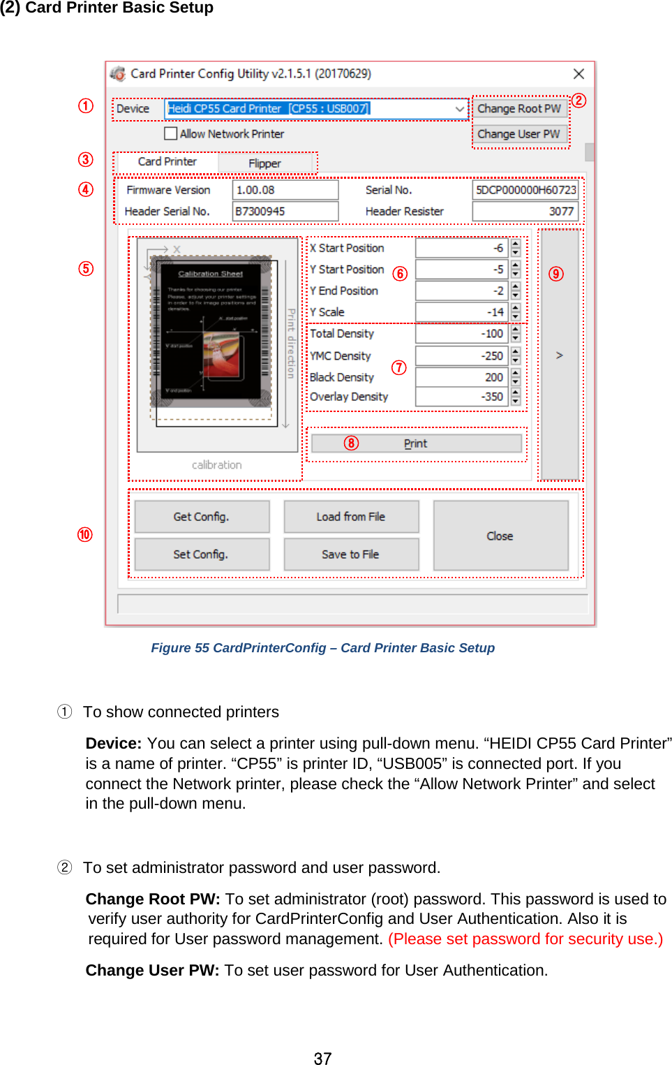
IDP CP55 Card Printer User Manual
IDP Corp., Ltd. Card Printer
UserManual.wiki
>
IDP
>
CP55 User Manual
User Manual
Navigation menu
Upload a User Manual
Namespaces
Wiki Guide
HTML
PDF
Info
Views
User Manual
Discussion / Help
Navigation

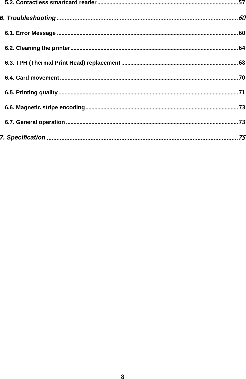
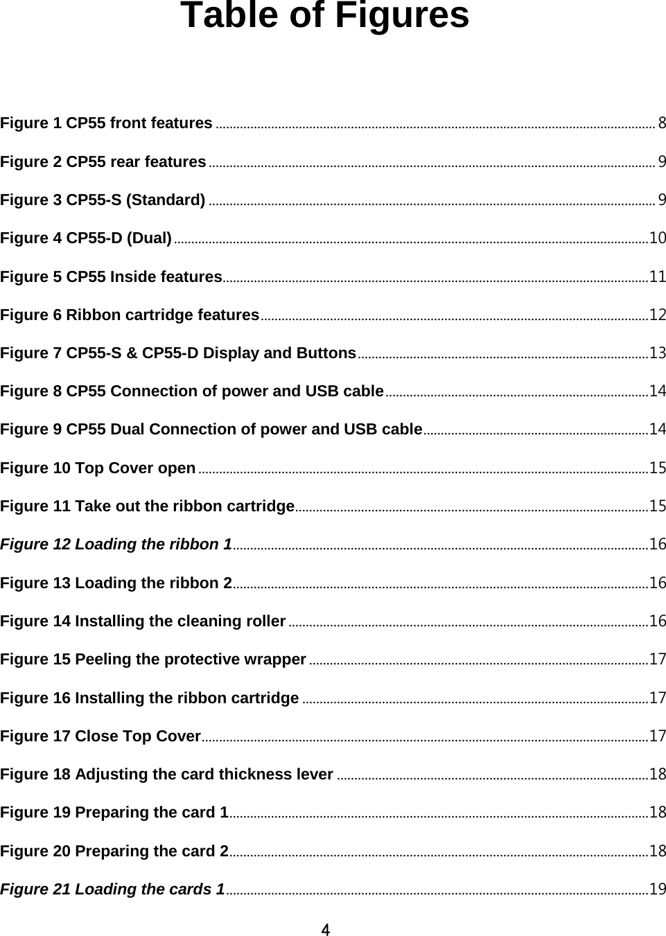
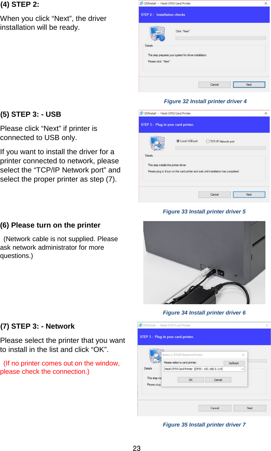

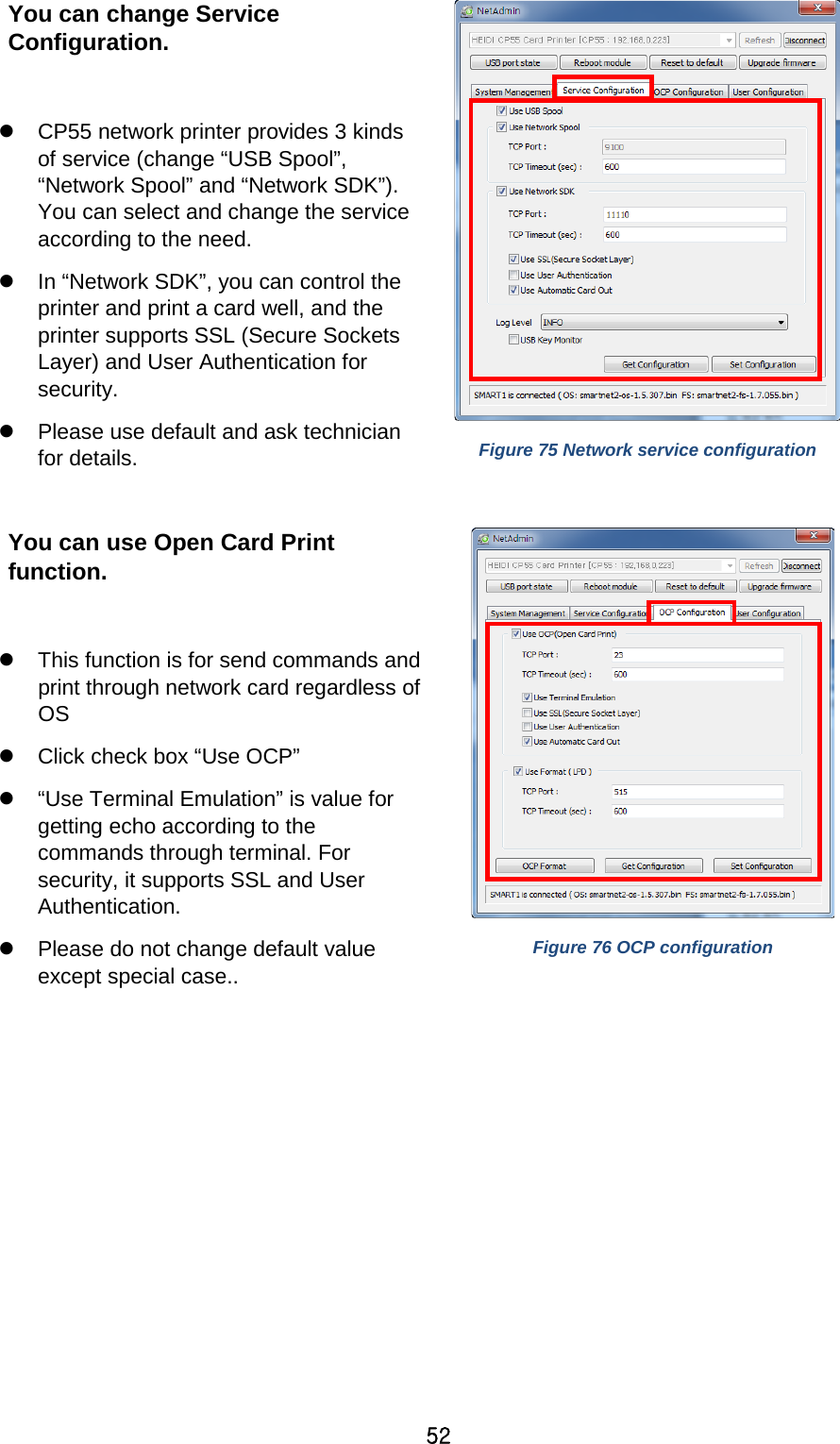
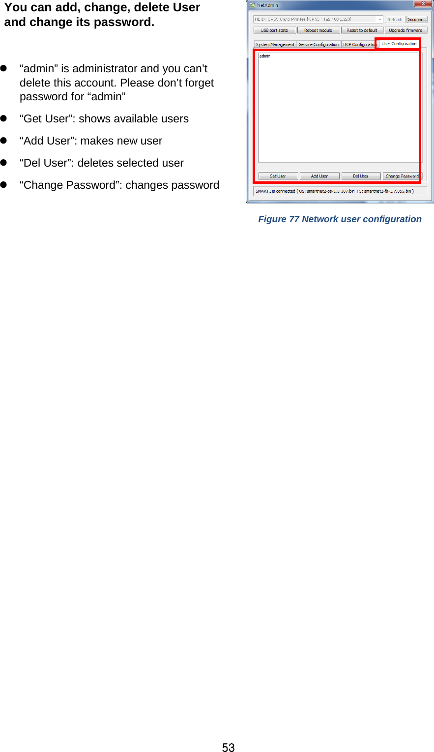
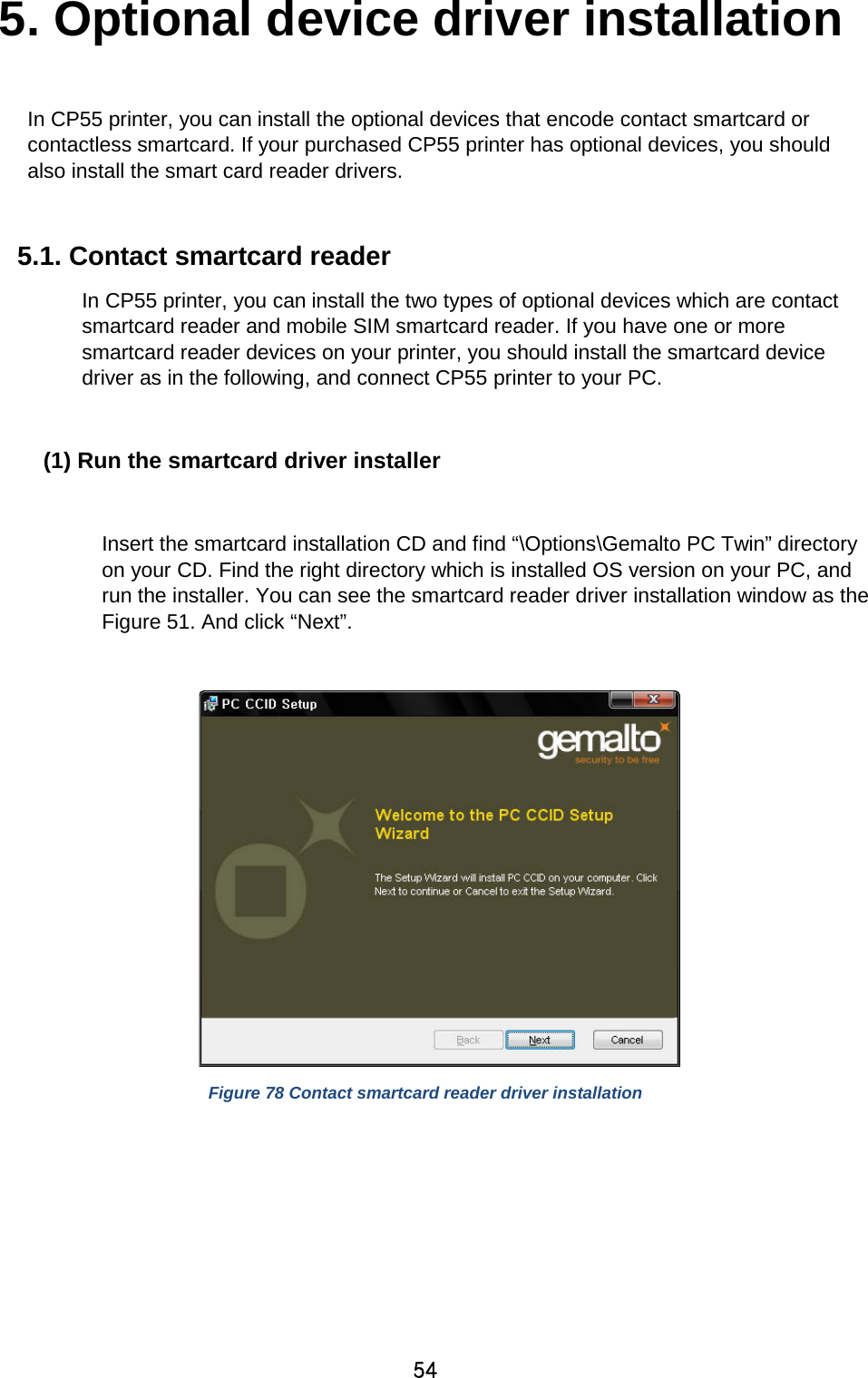
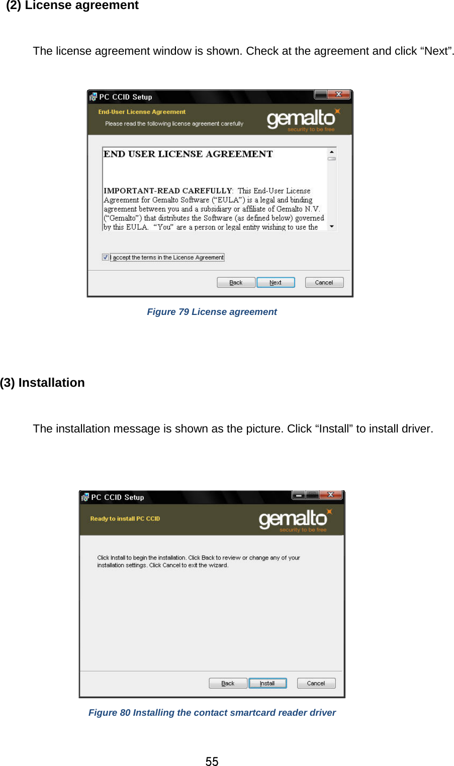
![27 (3) Input / Output [ Supply Tray ] Supply : You can select “Auto” if CP55 has 1 input hopper. Please select the hopper if it has a multi hopper. Tray : You can select “CR-80” because CP55 supports CR80 cards only. Figure 43 Input / Output (4) Printing Do Printing : You can select printing or not [ Print Side ] Side : Please select one side printing or both sides printing (It is possible only when you have a flipper.) [ Front / Back ] Color : You can select color or mono print. Flip : You can flip an image Media / Mask : You can indicate the area to print by using a predefined mask or user defined mask (white card, smartcard, Magnetic stripe card, etc.) on front or back side. [ Printing ] Ribbon : It shows the type of installed ribbon. You don’t need to select this option as CP55 recognizes ribbon automatically with RF Tag. Speed : Set printing speed and quality Mode : Set printing mode Standard : Default print mode. Prints all area of printing Figure 44 Printing You can define a mask. User defined mask uses BITMAP file (1012 X 636 pixels). Blue (RGB(0,0,255)): Print and Overlay Sky Blue (RGB(0,255,255)): Overlay only Pink (RGB(255,0,255)): Print only Yellow (RGB(255,255,0)): Florescent](https://usermanual.wiki/IDP/CP55/User-Guide-3557757-Page-27.png)
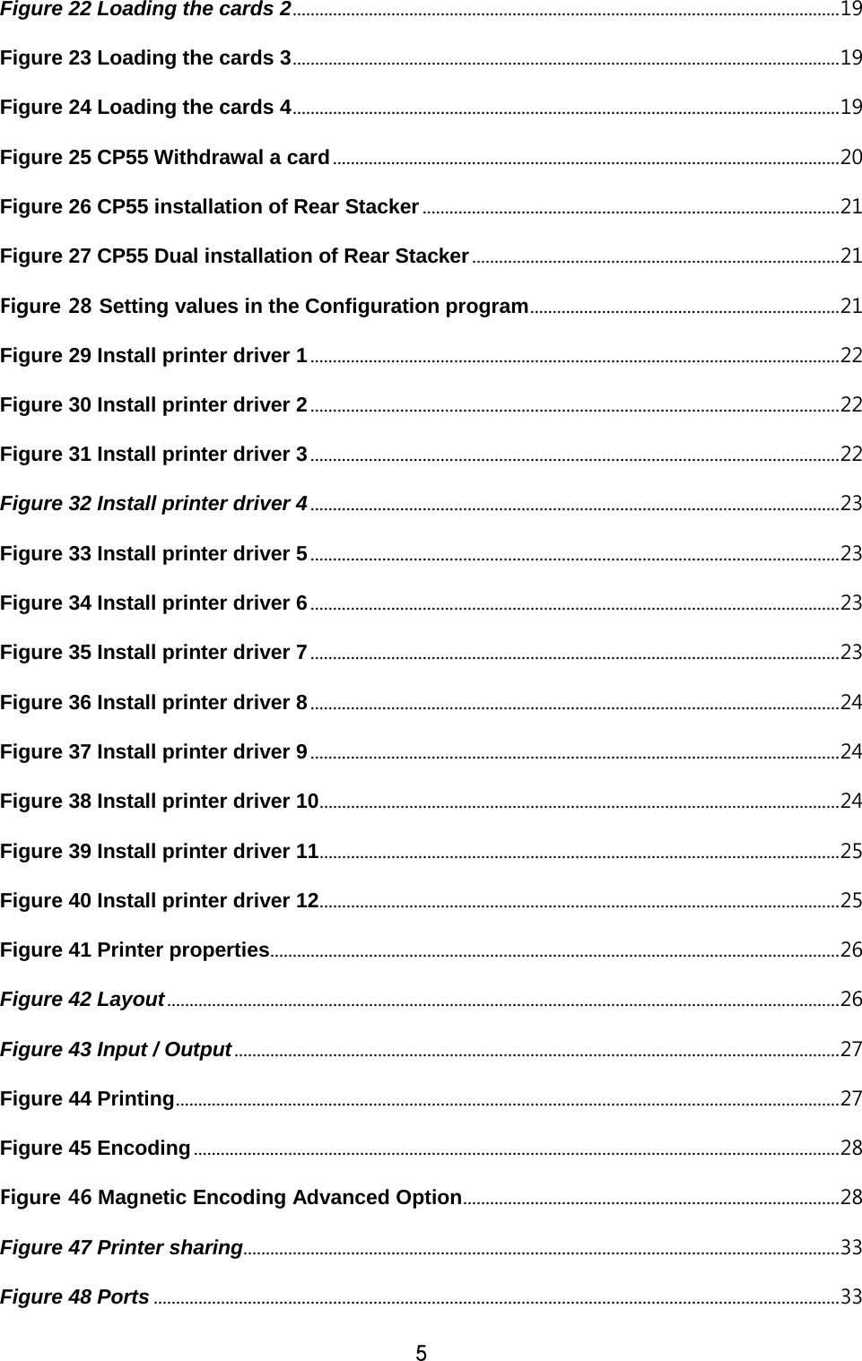
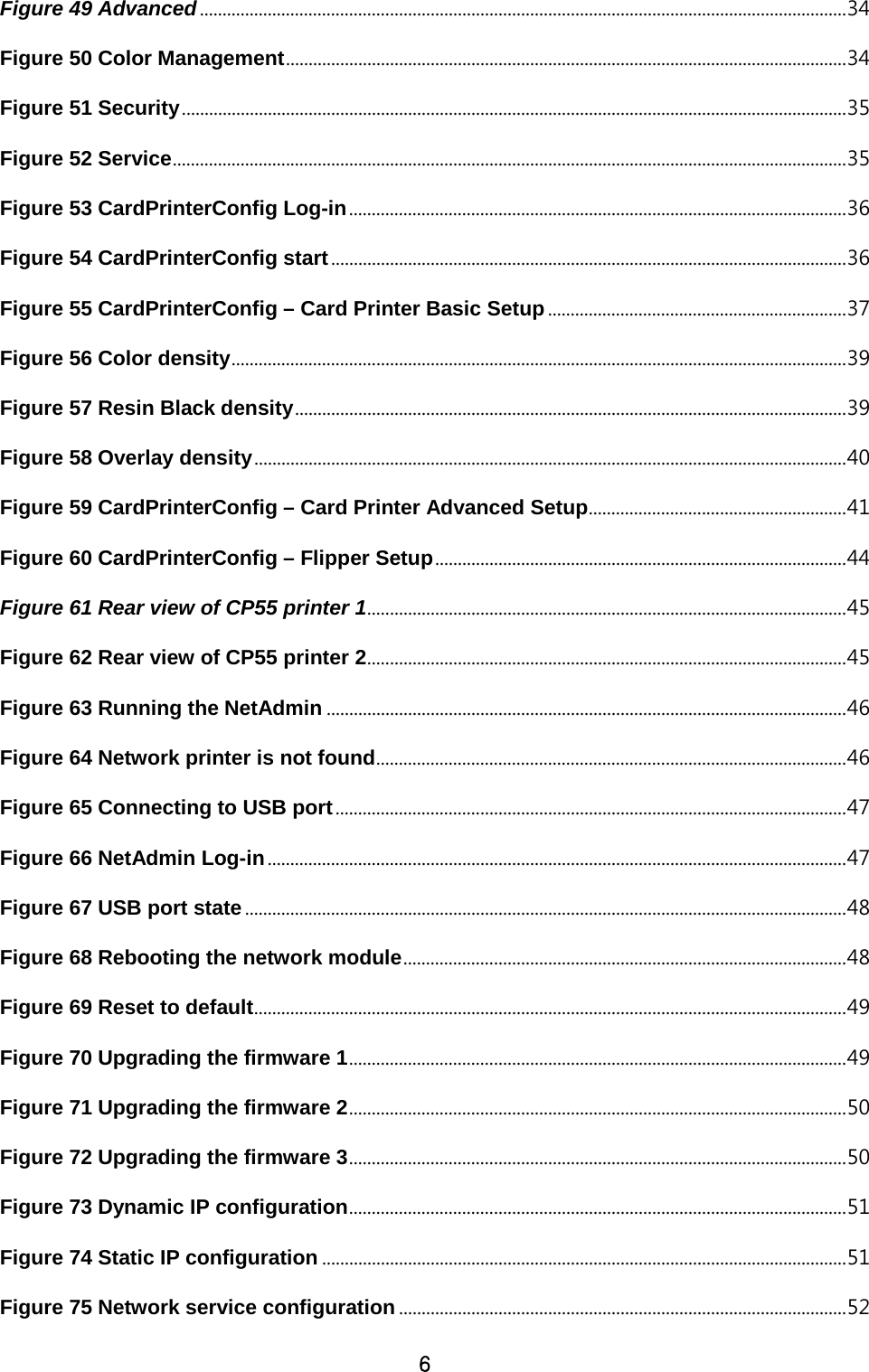
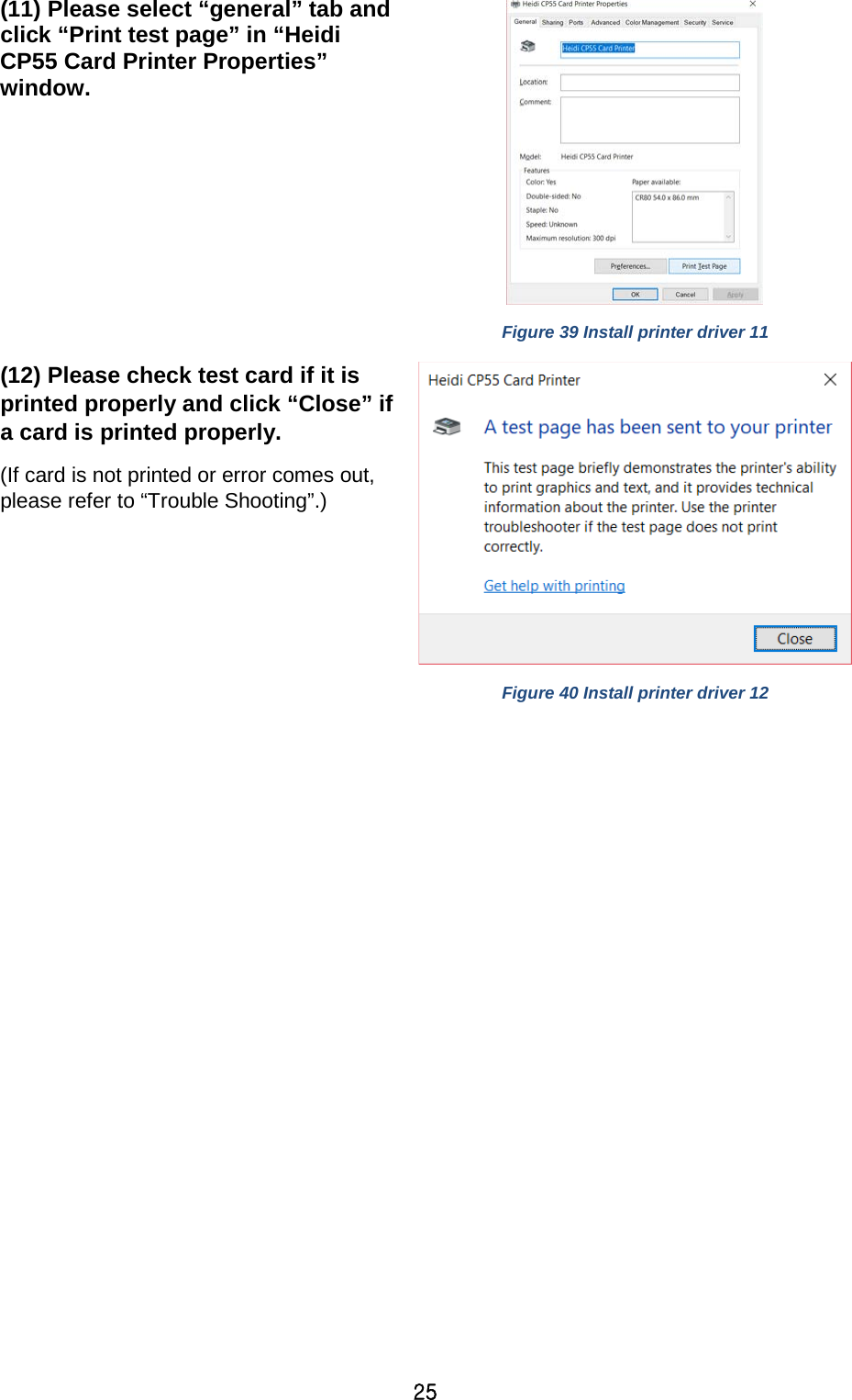
![28 Partial : Partial print mode. It is printed partially for the print area only. Printing speed can be faster than standard mode. Dither : There are 3 possible selections, Threshold, Random, and Diffusion Dither. It is performed with K and KO ribbon only. (Please select “Diffusion Dither” for high quality.) Ribbon Save : Select the split function or not when K ribbon is installed K ribbon Split : You can set the both sides (Front:YMCO, Back:K) to save color ribbon(YMCKO, HYMCKO, BYMCKO). It is only activated while printing both sides option is set. (5) Encoding This tap will be shown only when Magnetic encoder is installed. Do Encoding : You can select encoding or not Coercivity : You can select the coercivity to encode Loco : 300, 600 Oe. HiCo : 2760 Oe. SpCo : 4000 Oe. Auto : Defined automatically Repeat Count : You can select the retry count to encoding when encoding is failed Figure 45 Encoding (7) Encoding Advanced Option Card Stripe Side : The location of magnetic stripe [Bottom / Top] Before Flip : Do flipping before encoding [No / Yes] After Flip : Do flipping after encoding [No / Yes] Track Advanced Options : Format : Encoding format (IATA, ABA, MINS, JISII, Bits Mode) Figure 46 Magnetic Encoding Advanced Option](https://usermanual.wiki/IDP/CP55/User-Guide-3557757-Page-28.png)
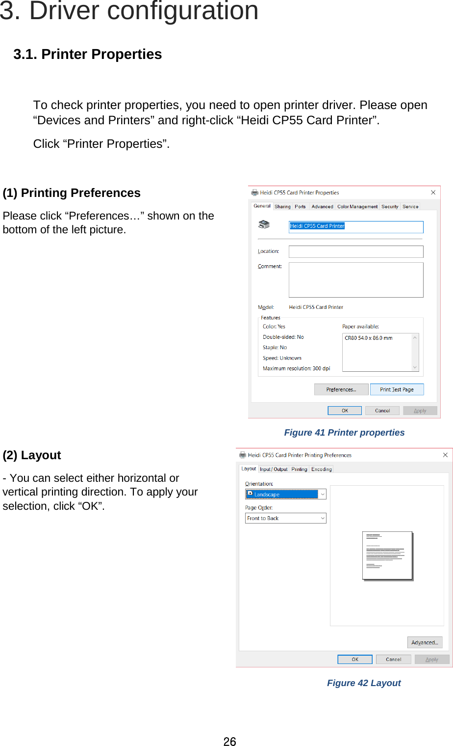
![30 3.2. Advanced Options To change the detailed configuration, In the ‘Layout’ tab shown, Please click “Advanced…” shown on the bottom of the ‘Layout’ tab of the ‘Preferences’. Reset Default Values: Reset to default. Color Correction: You can correct gamma for colors. You need to use CardPrinterConfig to adjust color densities. - Main [-100:100] : Correct gamma for all panels - Yellow [-100:100] : Correct gamma for yellow panel - Magenta [-100:100] : Correct gamma for magenta panel - Cyan [-100:100] : Correct gamma for cyan panel - Black [-100:100] : Correct gamma for black panel - Overlay [-100:100] : Correct gamma for overlay panel Position Processing: Set criteria for resin black processing. - Color [-32:32]: to set the position of color panels - Mono [-32:32]: to set the position of resin or mono panel - Overlay [-32:32]: to set the position of overlay panel Resin Black(K) Processing: Set criteria for resin black processing. - Text [0:100]: to set density criteria for extracting black objects - Dot [0:100]: to set density criteria for extracting black dots - Threshold [0:100]: to set density criteria on dithering - Dithering Degree [0:100]: to set sharpness on dithering - Resin Extraction: You can set the method to extract resin black when you use design programs. It will be set automatically.](https://usermanual.wiki/IDP/CP55/User-Guide-3557757-Page-30.png)
![31 Black Object: to extract resin black automatically for text, line, box, circle, binary images, etc. Black Text: to extract resin black for text only Black Dots: to extract resin black for all of black Black Dots only: to extract resin black for all of black and not to print on color panels Not Use: not to extract resin black Extra Controls : Other options - Fast Alignment [On/Off]: to set the position of input card to the magnetic encoder or normal printing. If it is on, the printer can save the time to encode - Rewritable Erase Density [0:100] : to set Erase Density on Rewritable printer Wait Option: - Wait at Internal Module Contactless Encoding Position [On/Off]: to set whether to wait at the Internal RF encoder or not Card Side [Front/Back]: to set the direction of card when waiting Wait Position [-100:100]: to set the position of card to wait from the criteria position. Unit is 0.1mm Wait Time [0:1000]: to set time to wait. Unit is second - Wait at External Module Contactless Encoding Position [On/Off]: to set whether to wait at the External RF encoder or not Card Side [Front/Back]: to set the direction of card when waiting Wait Position [-100:100]: to set the position of card to wait from the criteria position. Unit is 0.1mm Wait Time [0:1000]: to set time to wait. Unit is second - Wait at Internal Module Contact Encoding Position [On/Off]: to set whether to wait at the Internal IC encoder or not Card Side [Front/Back]: to set the direction of card when waiting](https://usermanual.wiki/IDP/CP55/User-Guide-3557757-Page-31.png)
![32 Wait Position [-100:100]: to set the position of card to wait from the criteria position. Unit is 0.1mm Wait Time [0:1000]: to set time to wait. Unit is second](https://usermanual.wiki/IDP/CP55/User-Guide-3557757-Page-32.png)
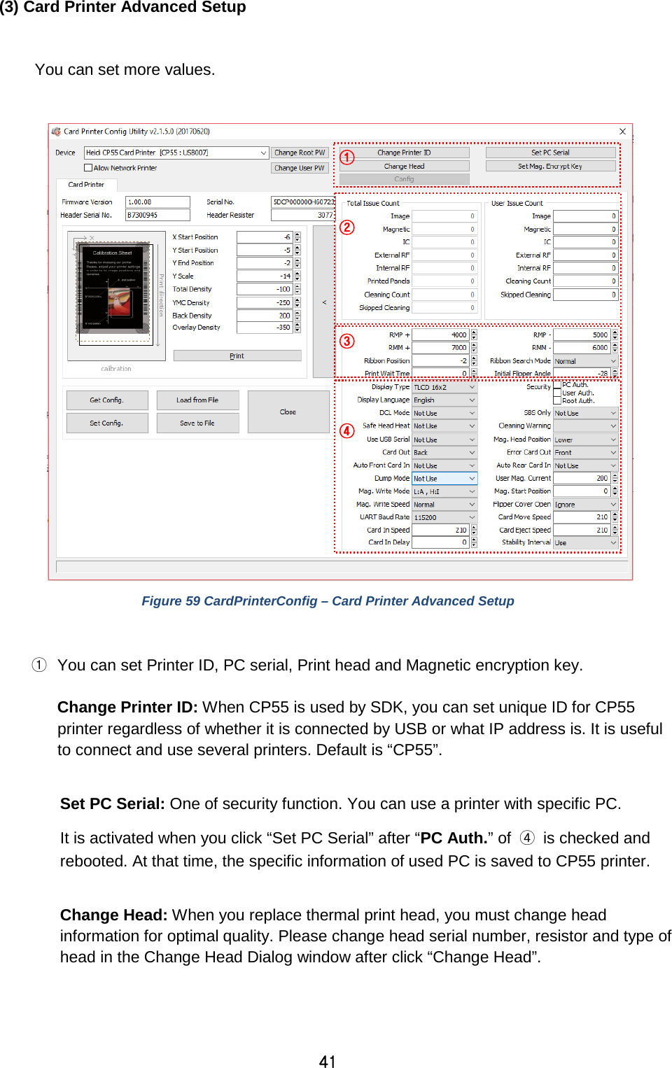
![43 SBS Only: Please enable it when you issue cards with software programed by SDK. This option disables printer device driver. Safe Head Heat: Set not to print if the print head is overheated. Cleaning Warning: Set to show the ‘Do cleaning’ message periodically Use USB Serial: When CP55 is connected to USB, it transmits the USB serial number to PC. Default is the same number used by all CP55. Please set this option when you use multiple CP55 printers connected to 1 PC via USB. It enables unique serial numbers for each USB. Mag. Head Position: CP55 can install the magnetic encoder on lower side of a card. Card Out: Set the way to eject cards. Error Card Out: Set the way to eject error cards. Auto Front Card In: Set to input a card automatically if the front card-in sensor detects a card. It is used for the KIOSK model. Auto Rear Card In: Set to input a card automatically if the rear card-in sensor detects a card. It is used for the KIOSK model. Dump Mode: It records log data to inspect the operation of printer. User Mag. Current: The default current value when the user selects to use the defined value when magnetic encoding Mag. Write Mode: You can order the way how to encode magnetic stripe. “L:A, H:I”: encodes 3 tracks at once for LoCo card and encodes at twice by dividing 1,3 and 2 track for HiCo card. Magnetic Start Position: Set the start position of magnetic stripe when you encode. Mag. Write Speed: You can order the speed to encode magnetic stripe. Flipper Cover Open: Set to notify the Flipper cover is opened or not. [Check / Ignore] UART Baud Rate: To set the communication speed (Baud rate) of the external device connected to Printer by serial. Card In Speed: set the speed of inputting a card Card Move Speed: set the speed of moving a card Card Eject Speed: set the speed of ejecting a card Card In Delay: set the delay time to operate the hopper motor. Stability Interval: select stability or faster speed. Default is ‘on’, stability.](https://usermanual.wiki/IDP/CP55/User-Guide-3557757-Page-43.png)